Embed Size (px)
Citation preview
PowerPoint Overheads for
Computer ArchitectureFrom Microprocessors To Supercomputers
Behrooz Parhami
Copyright © 2005 Oxford University Press
Oxford University Press Oxford New YorkAuckland Bangkok Buenos Aires Cape Town Chennai Dar es Salaam Delhi Hong Kong Istanbul Karachi KolkataKuala Lumpur Madrid Melbourne Mexico City Mumbai NairobiSão Paulo Shanghai Taipei Tokyo Toronto Copyright 2005 by Oxford University Press, Inc. Published by Oxford University Press, Inc.198 Madison Avenue, New York, New York 10016www.oup.com Oxford is a registered trademark of Oxford University Press All rights reserved. No part of this publication may be reproduced,stored in a retrieval system, or transmitted, in any form or by any means,electronic, mechanical, photocopying, recording, or otherwise,without the prior permission of Oxford University Press. ISBN-13: 978-0-19-522219-7ISBN 0-19-522219-9
Printing number: 9 8 7 6 5 4 3 2 1 Printed in the United States of America
2
3
4
Computer Architecture Parhami 5Copyright 2005 by Oxford University Press, Inc.
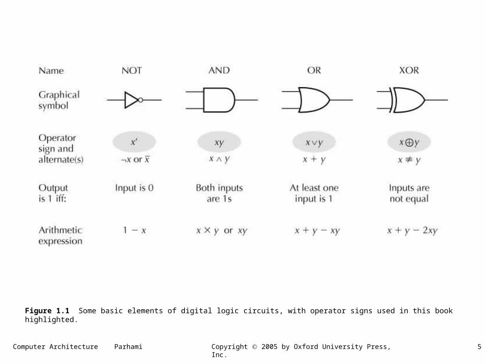
Figure 1.1 Some basic elements of digital logic circuits, with operator signs used in this book highlighted.
Computer Architecture Parhami 6Copyright 2005 by Oxford University Press, Inc.
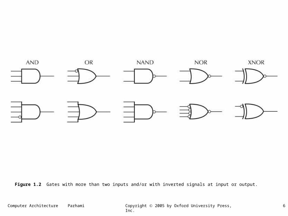
Figure 1.2 Gates with more than two inputs and/or with inverted signals at input or output.
Computer Architecture Parhami 7Copyright 2005 by Oxford University Press, Inc.
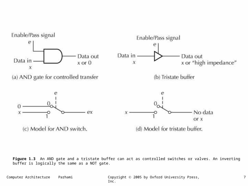
Figure 1.3 An AND gate and a tristate buffer can act as controlled switches or valves. An inverting buffer is logically the same as a NOT gate.
Computer Architecture Parhami 8Copyright 2005 by Oxford University Press, Inc.
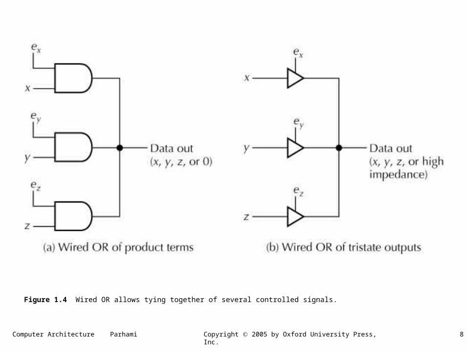
Figure 1.4 Wired OR allows tying together of several controlled signals.
Computer Architecture Parhami 9Copyright 2005 by Oxford University Press, Inc.
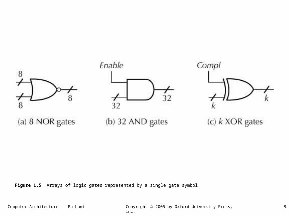
Figure 1.5 Arrays of logic gates represented by a single gate symbol.
Computer Architecture Parhami 10Copyright 2005 by Oxford University Press, Inc.
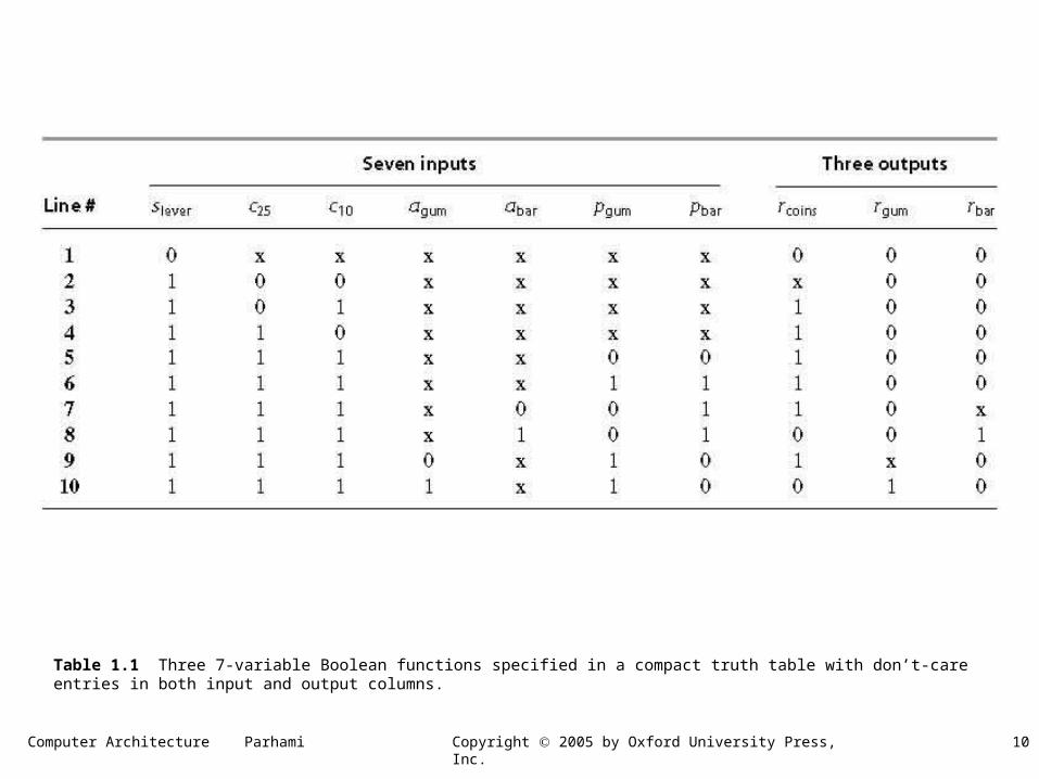
Table 1.1 Three 7-variable Boolean functions specified in a compact truth table with don’t-care entries in both input and output columns.
Computer Architecture Parhami 11Copyright 2005 by Oxford University Press, Inc.
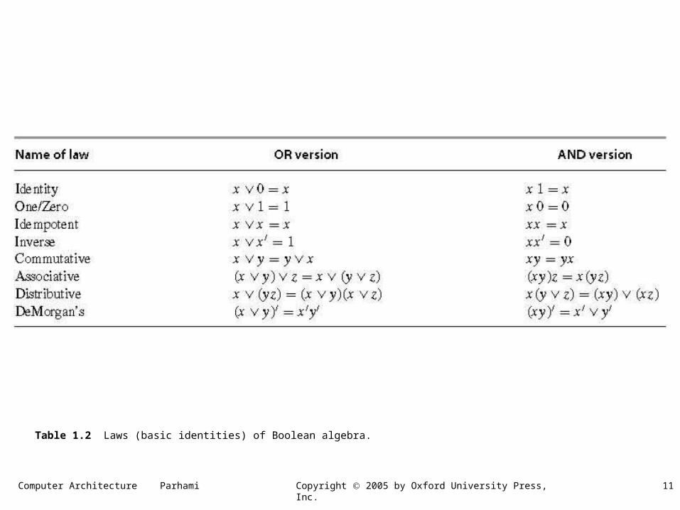
Table 1.2 Laws (basic identities) of Boolean algebra.
Computer Architecture Parhami 12Copyright 2005 by Oxford University Press, Inc.
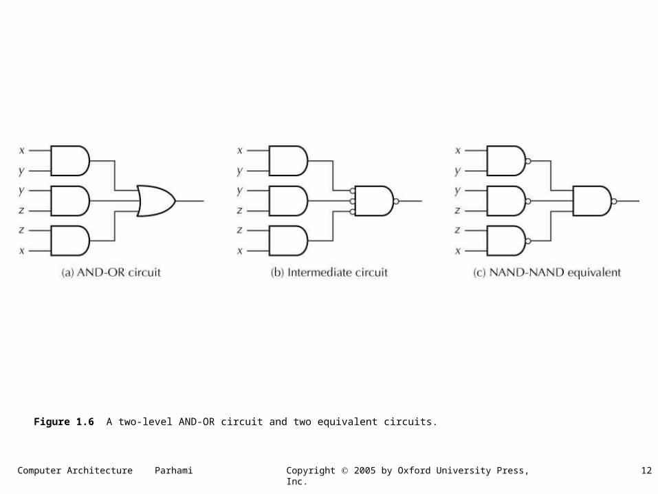
Figure 1.6 A two-level AND-OR circuit and two equivalent circuits.
Computer Architecture Parhami 13Copyright 2005 by Oxford University Press, Inc.
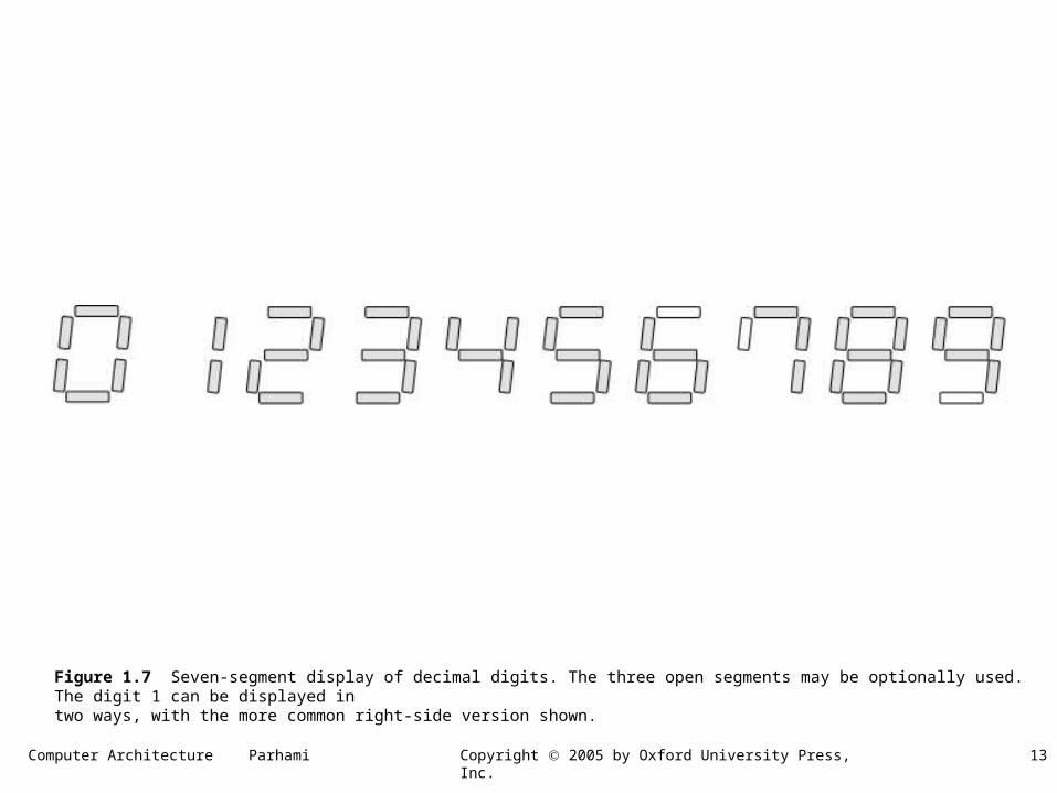
Figure 1.7 Seven-segment display of decimal digits. The three open segments may be optionally used. The digit 1 can be displayed intwo ways, with the more common right-side version shown.
Computer Architecture Parhami 14Copyright 2005 by Oxford University Press, Inc.
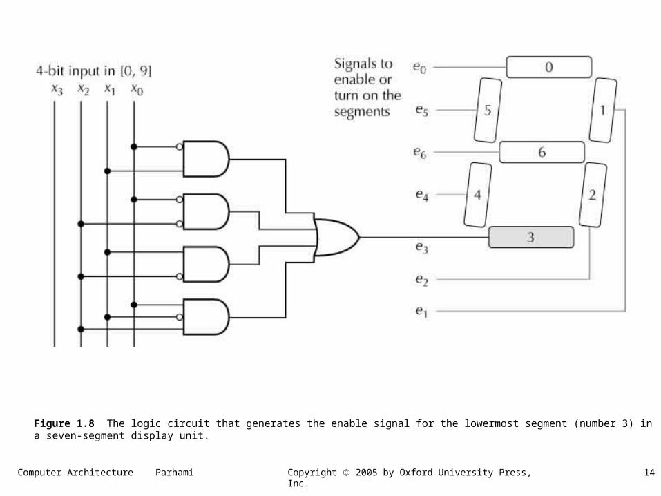
Figure 1.8 The logic circuit that generates the enable signal for the lowermost segment (number 3) in a seven-segment display unit.
Computer Architecture Parhami 15Copyright 2005 by Oxford University Press, Inc.
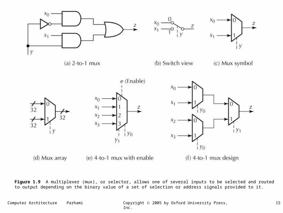
Figure 1.9 A multiplexer (mux), or selector, allows one of several inputs to be selected and routed to output depending on the binary value of a set of selection or address signals provided to it.
Computer Architecture Parhami 16Copyright 2005 by Oxford University Press, Inc.
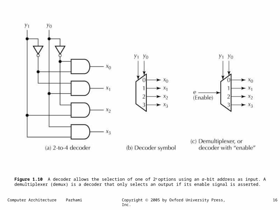
Figure 1.10 A decoder allows the selection of one of 2a options using an a-bit address as input. A demultiplexer (demux) is a decoder that only selects an output if its enable signal is asserted.
Computer Architecture Parhami 17Copyright 2005 by Oxford University Press, Inc.
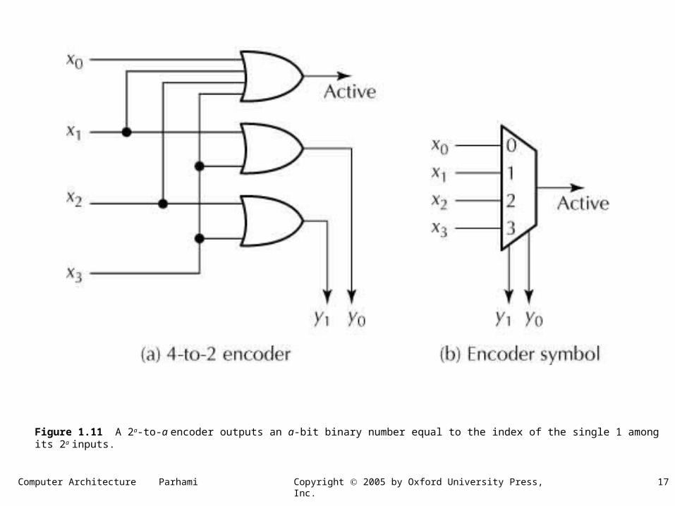
Figure 1.11 A 2a-to-a encoder outputs an a-bit binary number equal to the index of the single 1 among its 2a inputs.
Computer Architecture Parhami 18Copyright 2005 by Oxford University Press, Inc.
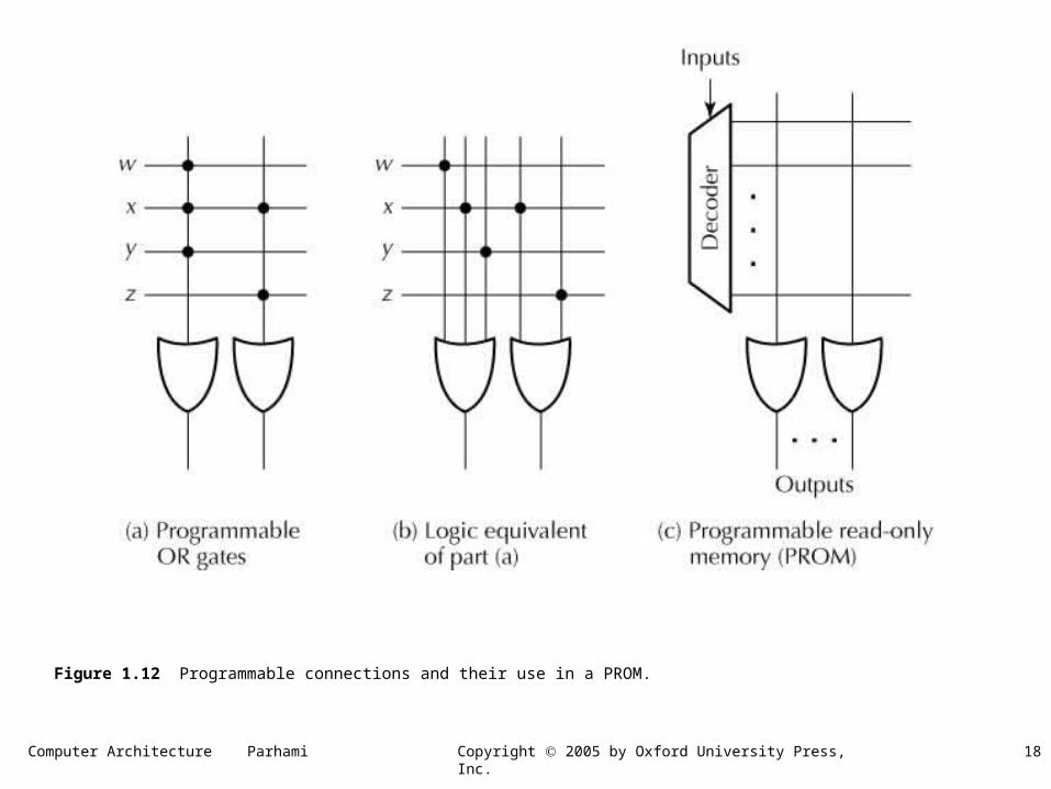
Figure 1.12 Programmable connections and their use in a PROM.
Computer Architecture Parhami 19Copyright 2005 by Oxford University Press, Inc.
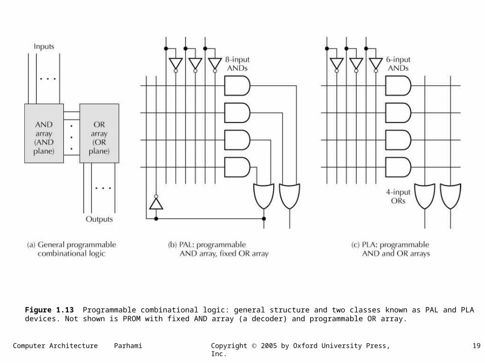
Figure 1.13 Programmable combinational logic: general structure and two classes known as PAL and PLA devices. Not shown is PROM with fixed AND array (a decoder) and programmable OR array.
Computer Architecture Parhami 20Copyright 2005 by Oxford University Press, Inc.
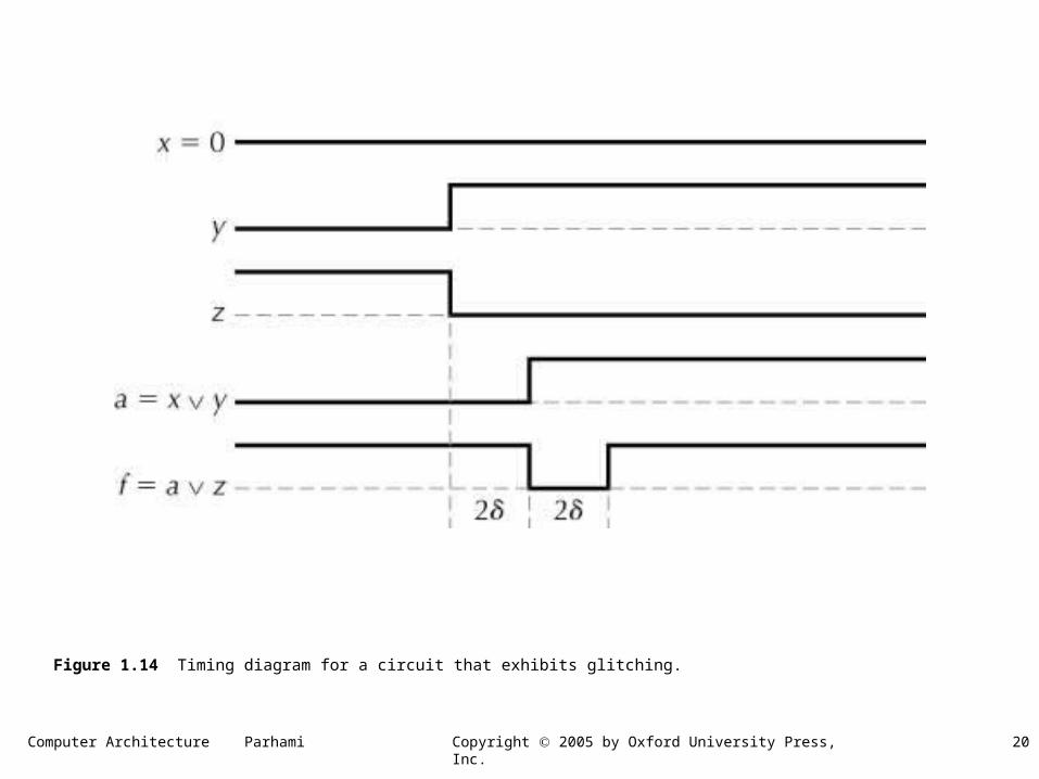
Figure 1.14 Timing diagram for a circuit that exhibits glitching.
Computer Architecture Parhami 21Copyright 2005 by Oxford University Press, Inc.
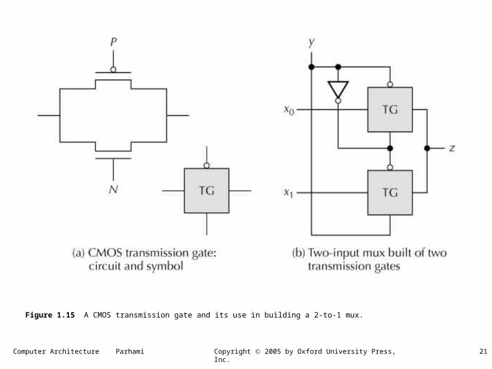
Figure 1.15 A CMOS transmission gate and its use in building a 2-to-1 mux.