Embed Size (px)
Citation preview
303--1Manual Table of Contents
GROUP
Powertrain 3SECTION TITLE PAGE
Engine System — General Information...................................................................................303-00-1Engine — 4.2L ......................................................................................................................... 303-01A-1Engine — 4.6L and 5.4L ......................................................................................................... 303-01B-1Engine Cooling...........................................................................................................................303-03-1Fuel Charging and Controls — 4.2L ..................................................................................... 303-04A-1Fuel Charging and Controls — 4.6L ..................................................................................... 303-04B-1Fuel Charging and Controls — 5.4L (2V) ............................................................................. 303-04C-1Fuel Charging and Controls — Natural Gas Vehicle .......................................................... 303-04D-1Accessory Drive .........................................................................................................................303-05-1Starting System..........................................................................................................................303-06-1Engine Ignition — 4.2L ........................................................................................................... 303-07A-1Engine Ignition — 4.6L ........................................................................................................... 303-07B-1Engine Ignition — 5.4L ........................................................................................................... 303-07C-1Engine Emission Control ..........................................................................................................303-08-1Intake Air Distribution and Filtering ........................................................................................303-12-1Evaporative Emissions..............................................................................................................303-13-1Electronic Engine Controls.......................................................................................................303-14-1Automatic Transmission — 4R100........................................................................................ 307-01A-1Automatic Transmission — 4R70W ...................................................................................... 307-01B-1Transaxle/Transmission Cooling..............................................................................................307-02-1Automatic Transaxle/Transmission External Controls ..........................................................307-05-1Manual Transaxle/Transmission and Clutch — General Information ..................................308-00-1Clutch ..........................................................................................................................................308-01-1Clutch Controls ..........................................................................................................................308-02-1Manual Transaxle/Transmission...............................................................................................308-03-1Transfer Case — General Information.................................................................................. 308-07A-1Transfer Case .......................................................................................................................... 308-07B-1Exhaust System — General Information.................................................................................309-00-1Fuel System — General Information — Gasoline and Diesel............................................ 310-00A-1Fuel System — General Information — Natural Gas.......................................................... 310-00B-1Fuel Tank and Lines—Gasoline and Diesel......................................................................... 310-01A-1Fuel Tank and Lines — Natural Gas..................................................................................... 310-01B-1Acceleration Control..................................................................................................................310-02-1Vehicle Speed Control...............................................................................................................310-03-1
SECTION 303-00 Engine System — General InformationVEHICLE APPLICATION: F-150/F-250
303-00-2 303-00-2Engine System — General Information
CONTENTS PAGE
DESCRIPTION AND OPERATIONEngine ...................................................................................................................................303-00-4
DIAGNOSIS AND TESTINGEngine ...................................................................................................................................303-00-4
Component Tests ..............................................................................................................303-00-8Compression Test—Compression Gauge Check .............................................................303-00-9Cylinder Leakage Detection ............................................................................................303-00-10Excessive Engine Oil Consumption ................................................................................303-00-14Inspection and Verification ................................................................................................303-00-5Intake Manifold Vacuum Test .........................................................................................303-00-12Oil Consumption Test......................................................................................................303-00-11Symptom Chart..................................................................................................................303-00-5Valve Train Analysis—Engine Off—Valve Cover Removed...........................................303-00-15Valve Train Analysis—Engine Running ..........................................................................303-00-15
GENERAL PROCEDURESBearing —Inspection...........................................................................................................303-00-52Camshaft —End Play, OHC Engines .................................................................................303-00-23Camshaft —Lobe Lift ..........................................................................................................303-00-24Camshaft —Lobe Surface ..................................................................................................303-00-24Camshaft —Push Rod Engines..........................................................................................303-00-22Camshaft —Runout.............................................................................................................303-00-24Camshaft Journal —Clearance, Plastigage Method ..........................................................303-00-21Camshaft Journal —Clearance, Push Rod Engines, Micrometer
Method.............................................................................................................................303-00-21Camshaft Journal —Diameter.............................................................................................303-00-20Connecting Rod —Bearing Journal Clearance ..................................................................303-00-36Connecting Rod —Bend .....................................................................................................303-00-35Connecting Rod —Bushing Diameter.................................................................................303-00-35Connecting Rod —Cleaning ...............................................................................................303-00-34Connecting Rod —Large End Bore....................................................................................303-00-34Connecting Rod —Piston Pin Side Clearance...................................................................303-00-36Connecting Rod —Twist .....................................................................................................303-00-35Crankshaft —Connecting Rod Journal Taper, Out of Round ............................................303-00-28Crankshaft —End Play .......................................................................................................303-00-27Crankshaft —Runout...........................................................................................................303-00-27Crankshaft Main Bearing Journal —Clearance ..................................................................303-00-26Crankshaft Main Bearing Journal —Diameter....................................................................303-00-25Crankshaft Main Bearing Journal —Taper .........................................................................303-00-25Cylinder Block —Core Plug Replacement..........................................................................303-00-47Cylinder Block —Distortion .................................................................................................303-00-46Cylinder Bore —Cleaning ...................................................................................................303-00-46Cylinder Bore —Honing ......................................................................................................303-00-44Cylinder Bore —Out-of-Round............................................................................................303-00-29Cylinder Bore —Taper ........................................................................................................303-00-28Cylinder Head —Distortion .................................................................................................303-00-44Exhaust Manifold —Inspection ...........................................................................................303-00-51Flywheel —Inspection .........................................................................................................303-00-43Piston —Diameter ...............................................................................................................303-00-31
303-00-3 303-00-3Engine System — General Information
CONTENTS PAGE
Piston —Inspection .............................................................................................................303-00-29Piston —Pin Diameter.........................................................................................................303-00-34Piston —Pin to Bore Diameter ...........................................................................................303-00-30Piston —Ring End Gap ......................................................................................................303-00-32Piston —Ring-to-Groove Clearance ...................................................................................303-00-33Piston —Selection...............................................................................................................303-00-31Piston —to Cylinder Bore Clearance..................................................................................303-00-31Push Rods —Cleaning .......................................................................................................303-00-19Push Rods —Inspection .....................................................................................................303-00-19Rocker Arms —Cleaning ....................................................................................................303-00-18Rocker Arms —Inspection ..................................................................................................303-00-19Roller Follower —Inspection...............................................................................................303-00-37Spark Plug —Thread Repair ..............................................................................................303-00-48Sprockets ............................................................................................................................303-00-18Valve —Guide Inner Diameter............................................................................................303-00-40Valve —Guide Reaming .....................................................................................................303-00-40Valve —Inspection ..............................................................................................................303-00-40Valve —Seat Inspection .....................................................................................................303-00-42Valve —Seat Runout ..........................................................................................................303-00-43Valve —Seat Width.............................................................................................................303-00-43Valve —Spring Free Length ...............................................................................................303-00-41Valve —Spring Installed Length .........................................................................................303-00-41Valve —Spring Squareness................................................................................................303-00-41Valve —Spring Strength .....................................................................................................303-00-42Valve —Stem Diameter ......................................................................................................303-00-38Valve —Stem to Valve Guide Clearance ...........................................................................303-00-39Valve Tappet —Inspection..................................................................................................303-00-37Valve Tappet —Leakdown Test, Hydraulic ........................................................................303-00-38
SPECIFICATIONS ..................................................................................................................303-00-52
303-00-4 303-00-4Engine System — General Information
• an exhaust emission control system. For additionalDESCRIPTION AND OPERATION
information, refer to Section 303-08. Engine• an evaporative emission control system. ForNote: This section contains information, steps and
additional information, refer to Section 303-13. procedures that may not be specific to your engine. The engine, fuel system, ignition system, emissionsThis section covers general procedures andsystem and exhaust system all affect exhaustdiagnosis and testing of the engine system, exceptemission levels and must be maintained accordingfor exhaust emission control devices, which areto the maintenance schedule. Refer to the Owner’scovered in the Powertrain Control/EmissionsGuide.Diagnosis Manual 1.Correct engine identification is required to orderThe engines incorporate the following features:parts; refer to the appropriate engine section.
• a closed positive crankcase ventilation (PCV)For complete vehicle and engine identificationsystem. For additional information, refer to codes, refer to Section 100-01.Section 303-08.
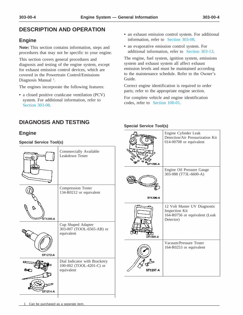
Special Service Tool(s)DIAGNOSIS AND TESTING
Engine Cylinder LeakEngineDetection/Air Pressurization Kit014-00708 or equivalentSpecial Service Tool(s)
Commercially AvailableLeakdown Tester
Engine Oil Pressure Gauge303-088 (T73L-6600-A)
Compression Tester134-R0212 or equivalent
12 Volt Master UV DiagnosticInspection Kit164-R0756 or equivalent (LeakDetector)
Cup Shaped Adapter303-007 (TOOL-6565-AB) orequivalent
Vacuum/Pressure Tester164-R0253 or equivalent
Dial Indicator with Bracketry100-002 (TOOL-4201-C) orequivalent
1 Can be purchased as a seperate item.
303-00-5 303-00-5Engine System — General Information
DIAGNOSIS AND TESTING (Continued)
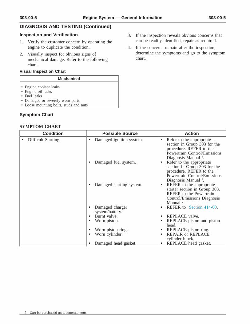
Inspection and Verification 3. If the inspection reveals obvious concerns thatcan be readily identified, repair as required.1. Verify the customer concern by operating the
engine to duplicate the condition. 4. If the concerns remain after the inspection,determine the symptoms and go to the symptom2. Visually inspect for obvious signs ofchart.mechanical damage. Refer to the following
chart.
Visual Inspection Chart
Mechanical
• Engine coolant leaks • Engine oil leaks • Fuel leaks • Damaged or severely worn parts • Loose mounting bolts, studs and nuts
Symptom Chart
SYMPTOM CHART
Condition Possible Source Action• Difficult Starting • Damaged ignition system. • Refer to the appropriate
section in Group 303 for theprocedure. REFER to thePowertrain Control/EmissionsDiagnosis Manual 2.
• Damaged fuel system. • Refer to the appropriatesection in Group 303 for theprocedure. REFER to thePowertrain Control/EmissionsDiagnosis Manual 2.
• Damaged starting system. • REFER to the appropriatestarter section in Group 303.REFER to the PowertrainControl/Emissions DiagnosisManual 2.
• Damaged charger • REFER to Section 414-00. system/battery.
• Burnt valve. • REPLACE valve. • Worn piston. • REPLACE piston and piston
head. • Worn piston rings. • REPLACE piston ring. • Worn cylinder. • REPAIR or REPLACE
cylinder block. • Damaged head gasket. • REPLACE head gasket.
2 Can be purchased as a seperate item.
303-00-6 303-00-6Engine System — General Information
DIAGNOSIS AND TESTING (Continued)
SYMPTOM CHART (Continued)
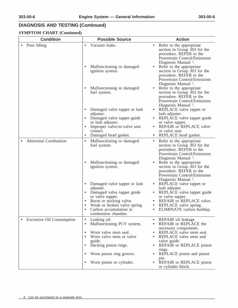
Condition Possible Source Action• Poor Idling • Vacuum leaks. • Refer to the appropriate
section in Group 303 for theprocedure. REFER to thePowertrain Control/EmissionsDiagnosis Manual 3.
• Malfunctioning or damaged • Refer to the appropriateignition system. section in Group 303 for the
procedure. REFER to thePowertrain Control/EmissionsDiagnosis Manual 3.
• Malfunctioning or damaged • Refer to the appropriatefuel system. section in Group 303 for the
procedure. REFER to thePowertrain Control/EmissionsDiagnosis Manual 3.
• Damaged valve tappet or lash • REPLACE valve tappet oradjuster. lash adjuster.
• Damaged valve tappet guide • REPLACE valve tappet guideor lash adjuster. or valve tappet.
• Improper valve-to-valve seat • REPAIR or REPLACE valvecontact. or valve seat.
• Damaged head gasket. • REPLACE head gasket. • Abnormal Combustion • Malfunctioning or damaged • Refer to the appropriate
fuel system. section in Group 303 for theprocedure. REFER to thePowertrain Control/EmissionsDiagnosis Manual 3.
• Malfunctioning or damaged • Refer to the appropriateignition system. section in Group 303 for the
procedure. REFER to thePowertrain Control/EmissionsDiagnosis Manual 3.
• Damaged valve tappet or lash • REPLACE valve tappet oradjuster. lash adjuster.
• Damaged valve tappet guide • REPLACE valve tappet guideor valve tappet. or valve tappet.
• Burnt or sticking valve. • REPAIR or REPLACE valve.• Weak or broken valve spring. • REPLACE valve spring. • Carbon accumulation in • ELIMINATE carbon buildup.
combustion chamber. • Excessive Oil Consumption • Leaking oil. • REPAIR oil leakage.
• Malfunctioning PCV system. • REPAIR or REPLACE thenecessary components.
• Worn valve stem seal. • REPLACE valve stem seal. • Worn valve stem or valve • REPLACE valve stem and
guide. valve guide. • Sticking piston rings. • REPAIR or REPLACE piston
rings. • Worn piston ring groove. • REPLACE piston and piston
pin. • Worn piston or cylinder. • REPAIR or REPLACE piston
or cylinder block.
3 Can be purchased as a seperate item.
303-00-7 303-00-7Engine System — General Information
DIAGNOSIS AND TESTING (Continued)
SYMPTOM CHART (Continued)
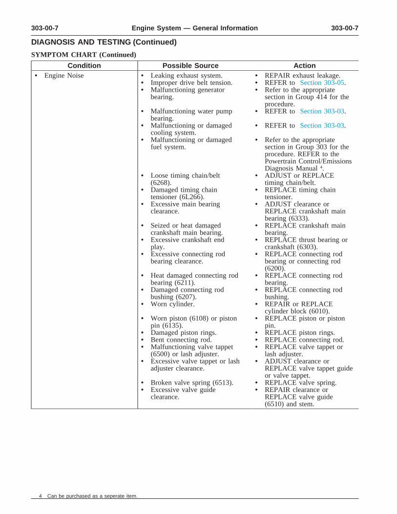
Condition Possible Source Action• Engine Noise • Leaking exhaust system. • REPAIR exhaust leakage.
• Improper drive belt tension. • REFER to Section 303-05. • Malfunctioning generator • Refer to the appropriate
bearing. section in Group 414 for theprocedure.
• Malfunctioning water pump • REFER to Section 303-03. bearing.
• Malfunctioning or damaged • REFER to Section 303-03. cooling system.
• Malfunctioning or damaged • Refer to the appropriatefuel system. section in Group 303 for the
procedure. REFER to thePowertrain Control/EmissionsDiagnosis Manual 4.
• Loose timing chain/belt • ADJUST or REPLACE(6268). timing chain/belt.
• Damaged timing chain • REPLACE timing chaintensioner (6L266). tensioner.
• Excessive main bearing • ADJUST clearance orclearance. REPLACE crankshaft main
bearing (6333). • Seized or heat damaged • REPLACE crankshaft main
crankshaft main bearing. bearing. • Excessive crankshaft end • REPLACE thrust bearing or
play. crankshaft (6303). • Excessive connecting rod • REPLACE connecting rod
bearing clearance. bearing or connecting rod(6200).
• Heat damaged connecting rod • REPLACE connecting rodbearing (6211). bearing.
• Damaged connecting rod • REPLACE connecting rodbushing (6207). bushing.
• Worn cylinder. • REPAIR or REPLACEcylinder block (6010).
• Worn piston (6108) or piston • REPLACE piston or pistonpin (6135). pin.
• Damaged piston rings. • REPLACE piston rings. • Bent connecting rod. • REPLACE connecting rod. • Malfunctioning valve tappet • REPLACE valve tappet or
(6500) or lash adjuster. lash adjuster. • Excessive valve tappet or lash • ADJUST clearance or
adjuster clearance. REPLACE valve tappet guideor valve tappet.
• Broken valve spring (6513). • REPLACE valve spring. • Excessive valve guide • REPAIR clearance or
clearance. REPLACE valve guide(6510) and stem.
4 Can be purchased as a seperate item.
303-00-8 303-00-8Engine System — General Information
DIAGNOSIS AND TESTING (Continued)
SYMPTOM CHART (Continued)
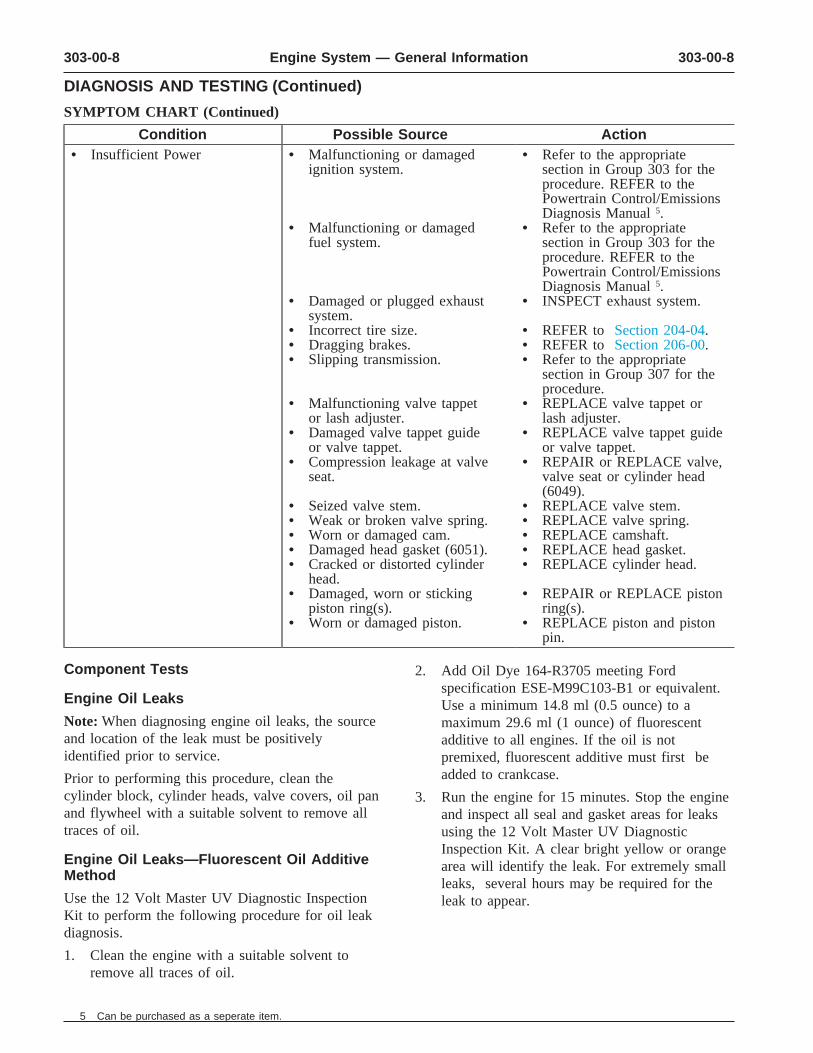
Condition Possible Source Action• Insufficient Power • Malfunctioning or damaged • Refer to the appropriate
ignition system. section in Group 303 for theprocedure. REFER to thePowertrain Control/EmissionsDiagnosis Manual 5.
• Malfunctioning or damaged • Refer to the appropriatefuel system. section in Group 303 for the
procedure. REFER to thePowertrain Control/EmissionsDiagnosis Manual 5.
• Damaged or plugged exhaust • INSPECT exhaust system. system.
• Incorrect tire size. • REFER to Section 204-04. • Dragging brakes. • REFER to Section 206-00. • Slipping transmission. • Refer to the appropriate
section in Group 307 for theprocedure.
• Malfunctioning valve tappet • REPLACE valve tappet oror lash adjuster. lash adjuster.
• Damaged valve tappet guide • REPLACE valve tappet guideor valve tappet. or valve tappet.
• Compression leakage at valve • REPAIR or REPLACE valve,seat. valve seat or cylinder head
(6049). • Seized valve stem. • REPLACE valve stem. • Weak or broken valve spring. • REPLACE valve spring. • Worn or damaged cam. • REPLACE camshaft. • Damaged head gasket (6051). • REPLACE head gasket. • Cracked or distorted cylinder • REPLACE cylinder head.
head. • Damaged, worn or sticking • REPAIR or REPLACE piston
piston ring(s). ring(s). • Worn or damaged piston. • REPLACE piston and piston
pin.
Component Tests 2. Add Oil Dye 164-R3705 meeting Fordspecification ESE-M99C103-B1 or equivalent.
Engine Oil Leaks Use a minimum 14.8 ml (0.5 ounce) to aNote: When diagnosing engine oil leaks, the source maximum 29.6 ml (1 ounce) of fluorescentand location of the leak must be positively additive to all engines. If the oil is notidentified prior to service. premixed, fluorescent additive must first be
added to crankcase.Prior to performing this procedure, clean thecylinder block, cylinder heads, valve covers, oil pan 3. Run the engine for 15 minutes. Stop the engineand flywheel with a suitable solvent to remove all and inspect all seal and gasket areas for leakstraces of oil. using the 12 Volt Master UV Diagnostic
Inspection Kit. A clear bright yellow or orangeEngine Oil Leaks—Fluorescent Oil Additive area will identify the leak. For extremely smallMethod leaks, several hours may be required for theUse the 12 Volt Master UV Diagnostic Inspection leak to appear.Kit to perform the following procedure for oil leakdiagnosis.
1. Clean the engine with a suitable solvent toremove all traces of oil.
5 Can be purchased as a seperate item.
303-00-9 303-00-9Engine System — General Information
DIAGNOSIS AND TESTING (Continued)
Leakage Points—Underhood Oil leaks at crimped seams in sheet metal parts andcracks in cast or stamped parts can be detectedExamine the following areas for oil leakage:when using the dye method.
• valve cover gaskets Compression Test—Compression Gauge• intake manifold gaskets Check
• cylinder head gaskets 1. Make sure the oil in the crankcase is of the
• oil bypass filter correct viscosity and at the proper level and thatthe battery (10655) is properly charged. Operate• oil filter adapter the vehicle until the engine is at normal• engine front cover operating temperature. Turn the ignition switch
• oil filter adapter and filter body to the OFF position, then remove all the spark• oil level indicator tube connection plugs (12405).
• oil pressure sensor 2. Set the throttle plates in the wide-open position.
3. Install a compression gauge such as theLeakage Points—Under Engine—WithCompression Tester in the No. 1 cylinder.Vehicle on Hoist
4. Install an auxiliary starter switch in the starting• oil pan gaskets (6710) circuit. With the ignition switch in the OFF• oil pan sealer position, and using the auxiliary starter switch,
crank the engine a minimum of five• oil pan rear seal (6723) compression strokes and record the highest• engine front cover gasket reading. Note the approximate number of
• crankshaft front seal (6700) compression strokes required to obtain thehighest reading.• crankshaft rear oil seal (6701)
5. Repeat the test on each cylinder, cranking the• crankshaft main bearing cap side bolts engine approximately the same number of• oil filter adapter and filter body compression strokes.
• oil cooler, if equipped Compression Test—Test Results
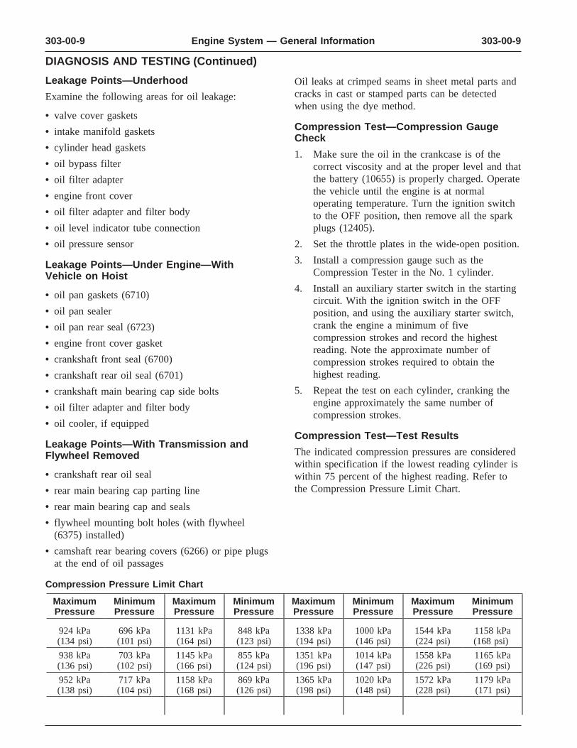
Leakage Points—With Transmission andThe indicated compression pressures are consideredFlywheel Removedwithin specification if the lowest reading cylinder is
• crankshaft rear oil seal within 75 percent of the highest reading. Refer tothe Compression Pressure Limit Chart.• rear main bearing cap parting line
• rear main bearing cap and seals
• flywheel mounting bolt holes (with flywheel(6375) installed)
• camshaft rear bearing covers (6266) or pipe plugsat the end of oil passages
Compression Pressure Limit Chart
Maximum Minimum Maximum Minimum Maximum Minimum Maximum MinimumPressure Pressure Pressure Pressure Pressure Pressure Pressure Pressure
924 kPa 696 kPa 1131 kPa 848 kPa 1338 kPa 1000 kPa 1544 kPa 1158 kPa(134 psi) (101 psi) (164 psi) (123 psi) (194 psi) (146 psi) (224 psi) (168 psi)
938 kPa 703 kPa 1145 kPa 855 kPa 1351 kPa 1014 kPa 1558 kPa 1165 kPa(136 psi) (102 psi) (166 psi) (124 psi) (196 psi) (147 psi) (226 psi) (169 psi)
952 kPa 717 kPa 1158 kPa 869 kPa 1365 kPa 1020 kPa 1572 kPa 1179 kPa(138 psi) (104 psi) (168 psi) (126 psi) (198 psi) (148 psi) (228 psi) (171 psi)
303-00-10 303-00-10Engine System — General Information
DIAGNOSIS AND TESTING (Continued)
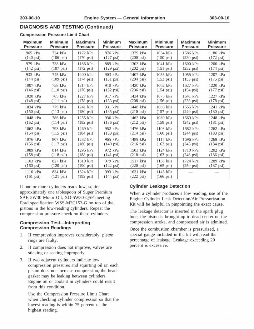
Compression Pressure Limit Chart
Maximum Minimum Maximum Minimum Maximum Minimum Maximum MinimumPressure Pressure Pressure Pressure Pressure Pressure Pressure Pressure
965 kPa 724 kPa 1172 kPa 876 kPa 1379 kPa 1034 kPa 1586 kPa 1186 kPa(140 psi) (106 psi) (170 psi) (127 psi) (200 psi) (150 psi) (230 psi) (172 psi)
979 kPa 738 kPa 1186 kPa 889 kPa 1303 kPa 1041 kPa 1600 kPa 1200 kPa(142 psi) (107 psi) (172 psi) (129 psi) (202 psi) (151 psi) (232 psi) (174 psi)
933 kPa 745 kPa 1200 kPa 903 kPa 1407 kPa 1055 kPa 1055 kPa 1207 kPa(144 psi) (109 psi) (174 psi) (131 psi) (204 psi) (153 psi) (153 psi) (175 psi)
1007 kPa 758 kPa 1214 kPa 910 kPa 1420 kPa 1062 kPa 1627 kPa 1220 kPa(146 psi) (110 psi) (176 psi) (132 psi) (206 psi) (154 psi) (154 psi) (177 psi)
1020 kPa 765 kPa 1227 kPa 917 kPa 1434 kPa 1075 kPa 1641 kPa 1227 kPa(148 psi) (111 psi) (178 psi) (133 psi) (208 psi) (156 psi) (238 psi) (178 psi)
1034 kPa 779 kPa 1241 kPa 931 kPa 1448 kPa 1083 kPa 1655 kPa 1241 kPa(150 psi) (113 psi) (180 psi) (135 psi) (210 psi) (157 psi) (240 psi) (180 psi)
1048 kPa 786 kPa 1255 kPa 936 kPa 1462 kPa 1089 kPa 1669 kPa 1248 kPa(152 psi) (114 psi) (182 psi) (136 psi) (212 psi) (158 psi) (242 psi) (181 psi)
1062 kPa 793 kPa 1269 kPa 952 kPa 1476 kPa 1103 kPa 1682 kPa 1262 kPa(154 psi) (115 psi) (184 psi) (138 psi) (214 psi) (160 psi) (244 psi) (183 psi)
1076 kPa 807 kPa 1282 kPa 965 kPa 1489 kPa 1117 kPa 1696 kPa 1269 kPa(156 psi) (117 psi) (186 psi) (140 psi) (216 psi) (162 psi) (246 psi) (184 psi)
1089 kPa 814 kPa 1296 kPa 972 kPa 1503 kPa 1124 kPa 1710 kPa 1202 kPa(158 psi) (118 psi) (188 psi) (141 psi) (218 psi) (163 psi) (248 psi) (186 psi)
1103 kPa 827 kPa 1310 kPa 979 kPa 1517 kPa 1138 kPa 1724 kPa 1289 kPa(160 psi) (120 psi) (190 psi) (142 psi) (220 psi) (165 psi) (250 psi) (187 psi)
1110 kPa 834 kPa 1324 kPa 993 kPa 1631 kPa 1145 kPa — —(161 psi) (121 psi) (192 psi) (144 psi) (222 psi) (166 psi)
Cylinder Leakage DetectionIf one or more cylinders reads low, squirtapproximately one tablespoon of Super Premium When a cylinder produces a low reading, use of theSAE 5W30 Motor Oil, XO-5W30-QSP meeting Engine Cylinder Leak Detection/Air PressurizationFord specification WSS-M2C153-G on top of the Kit will be helpful in pinpointing the exact cause.pistons in the low-reading cylinders. Repeat the
The leakage detector is inserted in the spark plugcompression pressure check on these cylinders.hole, the piston is brought up to dead center on thecompression stroke, and compressed air is admitted.Compression Test—Interpreting
Compression Readings Once the combustion chamber is pressurized, aspecial gauge included in the kit will read the1. If compression improves considerably, pistonpercentage of leakage. Leakage exceeding 20rings are faulty.percent is excessive.2. If compression does not improve, valves are
sticking or seating improperly.
3. If two adjacent cylinders indicate lowcompression pressures and squirting oil on eachpiston does not increase compression, the headgasket may be leaking between cylinders.Engine oil or coolant in cylinders could resultfrom this condition.
Use the Compression Pressure Limit Chartwhen checking cylinder compression so that thelowest reading is within 75 percent of thehighest reading.
303-00-11 303-00-11Engine System — General Information
DIAGNOSIS AND TESTING (Continued)
While the air pressure is retained in the cylinder, 5. Verify the spark plugs are not oil saturated. Iflisten for the hiss of escaping air. A leak at the the spark plugs are oil saturated andintake valve (6507) will be heard in the throttle compression is good it can be assumed thebody (9E926). A leak at the exhaust valve (6505) valve seals or valve guides are at fault.can be heard at the tail pipe. Leakage past the 6. Perform an oil consumption test:piston rings will be audible at the positive crankcase
a. Drain the engine oil, remove the oil bypassventilation (PCV) connection. If air is passingfilter (6714) and refill with one liter (quart)through a blown head gasket to an adjacentless than the recommended amount. cylinder, the noise will be evident at the spark plug
hole of the cylinder into which the air is leaking. b. Run the engine for three minutes (10Cracks in the cylinder block or gasket leakage into minutes if cold), and allow the oil to drainthe cooling system may be detected by a stream of back for at least five minutes with thebubbles in the radiator (8005). vehicle on a level surface.
c. Remove oil level dipstick and wipe clean.Oil Consumption Test(Do not wipe with anything contaminated
The following diagnostic procedure is used to with silicone compounds.) Reinstall the oildetermine the source of excessive internal oil level dipstick, being sure to seat it firmlyconsumption. in the oil level indicator tube (6754).1. Note: Oil use is normally greater during the Remove the oil level dipstick and draw a
first 16,100 km (10,000 miles) of service. As mark on the back (unmarked) surface at themileage increases, oil use generally decreases. indicated oil level. This level should beVehicles in normal service should get at least about the same as the MIN or ADD mark1,450 km per liter (900 miles per quart) after on the face of the oil level dipstick. 16,100 km (10,000 miles) of service. High d. Add one liter (quart) of oil. Restart thespeed driving, towing, high ambient temperature engine and allow to idle for at least twoand other factors may result in greater oil use. minutes. Shut off the engine and allow theDefine excessive oil consumption, such as the oil to drain back for at least five minutes.number of miles driven per liter (quart) of oil Mark the oil level dipstick, using theused. Also determine customer’s driving habits, procedure above. such as sustained high speed operation, towing, e. Record the vehicle mileage. extended idle and other considerations.
f. Instruct the customer to drive the vehicle2. Verify that the engine has no external oil leak as usual and perform the following:
as described under Engine Oil Leaks in the•Check the oil level regularly at intervalsDiagnosis and Testing portion of this section.of 160 to 240 km (100-150 miles).
3. Verify that the engine has the correct oil level•Return to the service point when the oildipstick (6750).level drops below the lower (MIN or
4. Verify that the engine is not being run in an ADD) mark on the oil level dipstick. overfilled condition. Check the oil level at least
•Add only full liters (quarts) of the samefive minutes after a hot shutdown with theoil in an emergency. Note the mileage atvehicle parked on a level surface. In no casewhich the oil is added. should the level be above MAX or the letter F
in FULL. If significantly overfilled, performsteps 6a through 6d.
303-00-12 303-00-12Engine System — General Information
DIAGNOSIS AND TESTING (Continued)
g. Check the oil level under the same b. Check piston ring clearance, ring gap andconditions and at the same location as in ring orientation. Repair as required. Steps 5c and 5d. c. Check for excessive bearing clearance.•Measure the distance from the oil level to Repair as required. the UPPER mark on the oil level dipstick 13. Repeat the oil consumption test (Step 6) toand record. confirm the oil consumption concern has been
•Measure the distance between the two resolved.scribe marks and record.
Intake Manifold Vacuum Test•Divide the first measurement by the
Bring the engine to normal operating temperature.second. Connect the Vacuum/Pressure Tester to the intake
•Divide the distance driven during the oil manifold. Run the engine at the specified idle speed.test by the result. This quantity is the
The vacuum gauge should read between 51-74 kPaapproximate oil consumption rate in(15-22 in-Hg) depending upon the engine conditionkilometers per liter or in miles per quart. and the altitude at which the test is performed.
h. If the oil consumption rate is unacceptable, Subtract 4.0193 kPa (1 in-Hg) from the specifiedgo to Step 7. reading for every 304.8 m (1,000 feet) of elevation
7. Check the positive crankcase ventilation (PCV) above sea level.system. Make sure the system is not plugged. The reading should be steady. If necessary, adjust
8. Check for plugged oil drain-back holes in the the gauge damper control (where used) if the needlecylinder heads and cylinder block. is fluttering rapidly. Adjust the damper until the
needle moves easily without excessive flutter.9. If the condition still exists after performing theabove steps, go to Step 10. Intake Manifold Vacuum Test—Interpreting
10. Perform a cylinder compression test or perform Vacuum Gauge Readingsa cylinder leak detection test with Engine A careful study of the vacuum gauge reading whileCylinder Leak Detection/Air Pressurization Kit. the engine is idling will help pinpoint trouble areas.This can help determine the source of oil Always conduct other appropriate tests beforeconsumption such as valves, piston rings or arriving at a final diagnostic decision. Vacuumother areas. gauge readings, although helpful, must be
11. Note: After determining if worn parts should be interpreted carefully.replaced, make sure correct replacement parts Most vacuum gauges have a normal band indicatedare used. on the gauge face.Check valve guides for excessive guideclearance. REPLACE all valve stem seals(6571) after verifying valve guide clearance.
12. Worn or damaged internal engine componentscan cause excessive oil consumption. Smalldeposits of oil on the tips of spark plugs can bea clue to internal oil consumption. If internal oilconsumption still persists, proceed as follows:
a. Remove the engine from the vehicle andplace it on an engine work stand. Removethe intake manifolds (9424), cylinder heads,oil pan (6675) and oil pump (6600).
303-00-13 303-00-13Engine System — General Information
DIAGNOSIS AND TESTING (Continued)
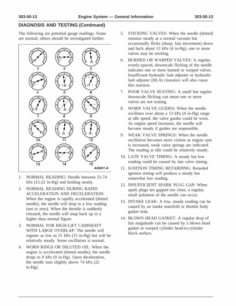
The following are potential gauge readings. Some 5. STICKING VALVES: When the needle (dotted)are normal; others should be investigated further. remains steady at a normal vacuum but
occasionally flicks (sharp, fast movement) downand back about 13 kPa (4 in-Hg), one or morevalves may be sticking.
6. BURNED OR WARPED VALVES: A regular,evenly-spaced, downscale flicking of the needleindicates one or more burned or warped valves.Insufficient hydraulic lash adjuster or hydrauliclash adjuster (HLA) clearance will also causethis reaction.
7. POOR VALVE SEATING: A small but regulardownscale flicking can mean one or morevalves are not seating.
8. WORN VALVE GUIDES: When the needleoscillates over about a 13 kPa (4 in-Hg) rangeat idle speed, the valve guides could be worn.As engine speed increases, the needle willbecome steady if guides are responsible.
9. WEAK VALVE SPRINGS: When the needleoscillation becomes more violent as engine rpmis increased, weak valve springs are indicated.The reading at idle could be relatively steady.
10. LATE VALVE TIMING: A steady but lowreading could be caused by late valve timing.
11. IGNITION TIMING RETARDING: Retardedignition timing will produce a steady but
1. NORMAL READING: Needle between 51-74 somewhat low reading.kPa (15-22 in-Hg) and holding steady.
12. INSUFFICIENT SPARK PLUG GAP: When2. NORMAL READING DURING RAPID spark plugs are gapped too close, a regular,
ACCELERATION AND DECELERATION: small pulsation of the needle can occur.When the engine is rapidly accelerated (dotted
13. INTAKE LEAK: A low, steady reading can beneedle), the needle will drop to a low readingcaused by an intake manifold or throttle body(not to zero). When the throttle is suddenlygasket leak.released, the needle will snap back up to a
14. BLOWN HEAD GASKET: A regular drop ofhigher than normal figure.fair magnitude can be caused by a blown head3. NORMAL FOR HIGH-LIFT CAMSHAFTgasket or warped cylinder head-to-cylinderWITH LARGE OVERLAP: The needle willblock surface.register as low as 51 kPa (15 in-Hg) but will be
relatively steady. Some oscillation is normal.
4. WORN RINGS OR DILUTED OIL: When theengine is accelerated (dotted needle), the needledrops to 0 kPa (0 in-Hg). Upon deceleration,the needle runs slightly above 74 kPa (22in-Hg).
303-00-14 303-00-14Engine System — General Information
DIAGNOSIS AND TESTING (Continued)
15. RESTRICTED EXHAUST SYSTEM: When the The following is a partial list of conditions that canengine is first started and is idled, the reading affect oil consumption rates:may be normal, but as the engine rpm is
• engine duty cycle increased, the back pressure caused by a• operator driving habits clogged muffler (5230), kinked tail pipe or
other concerns will cause the needle to slowly • ambient temperature drop to 0 kPa (0 in-Hg). The needle then may • quality and viscosity of the oil slowly rise. Excessive exhaust clogging will
Operation under varying conditions can frequentlycause the needle to drop to a low point even ifbe misleading. A vehicle that has been run forthe engine is only idling.several thousand miles on short trips or in
16. When vacuum leaks are indicated, search out below-freezing ambient temperatures may haveand correct the cause. Excess air leaking into consumed a ‘‘normal’’ amount of oil. However,the system will upset the fuel mixture and cause when checking the engine oil level, it may measureconcerns such as rough idle, missing on up to the FULL or MAX on the oil level dipstickacceleration or burned valves. If the leak exists due to dilution (condensation and fuel) in the enginein an accessory unit such as the power brake crankcase. The vehicle might then be driven at highbooster (2005), the unit will not function speeds on the highway where the condensation andcorrectly. Always fix vacuum leaks. fuel boil off. The next time the engine oil is
checked, it may appear that a liter (quart) of oil wasExcessive Engine Oil Consumptionused in about 160 km (100 miles). This perceived
The amount of oil an engine uses will vary with the 160 km (100 miles) per liter (quart) oil consumptionway the vehicle is driven in addition to normal rate causes customer concern even though the actualengine-to-engine variation. This is especially true overall oil consumption rate is about 2400 km (1500during the first 16,100 km (10,000 miles) when a miles) per liter (quart).new engine is being broken in or until certain
Make sure the selected engine oil meets the currentinternal engine components become conditioned.recommended API performance category with SAEVehicles used in heavy-duty operation may useviscosity grade as shown in the vehicle Owner’smore oil. The following are examples of heavy-dutyGuide. It is also important that the engine oil isoperation:changed at the intervals specified. Refer to the
• trailer towing applications Vehicle Owner’s Guide.• severe loading applications
Oil Pressure Test• sustained high speed operation
1. Disconnect and remove the oil pressure sensorEngines need oil to lubricate the following internal (9278) from the engine.components:
2. Connect the Engine Oil Pressure Gauge to the• cylinder block cylinder walls oil pressure sender oil galley port.
• pistons and piston, pin and rings (6102) 3. Run the engine until normal operatingtemperature is reached.• intake and exhaust valve stems
4. Run the engine at the specified rpm and record• intake and exhaust valve guides the gauge reading.
• all internal engine components 5. The oil pressure should be within specifications;
When the pistons move downward, a thin film of refer to the specification chart in the appropriateoil is left on the cylinder walls. As the vehicle is engine section.operated, some oil is also drawn into thecombustion chambers past the intake and exhaustvalve stem seals and burned.
303-00-15 303-00-15Engine System — General Information
DIAGNOSIS AND TESTING (Continued)
Valve Train Analysis—Engine Off, Valves6. If the pressure is not within specification, checkand Cylinder Headthe following possible sources:
• insufficient oil • Check for plugged oil drain back holes.
• oil leakage • Check for worn or damaged valve tips.
• worn or damaged oil pump • Check for missing or damaged guide-mountedvalve stem seal. • oil pump screen cover and tube (6622)
• Check collapsed valve tappet gap. • excessive main bearing clearance• Check installed valve spring height. • excessive connecting rod bearing clearance• Check for missing or worn valve spring seats.
Valve Train Analysis—Engine Off—Valve• Check for plugged oil metering orifice in cylinderCover Removed
head oil reservoir (if equipped). Check for damaged or severely worn parts and
Static checks (engine off) are to be made on thecorrect assembly. Make sure correct parts are usedengine prior to the dynamic procedure.with the static engine analysis as follows.
Valve Train Analysis—Engine RunningValve Train Analysis—Engine Off, RockerArm • Start the engine and, while idling, check for
proper operation of all parts. Check the following:• Check for loose mounting bolts, studs and nuts.
• Check for plugged oil feed in the rocker arms Valve Train Analysis—Engine Running,(6564) or cylinder head. Positive Rotator and Valve Spring Retainer
KeysValve Train Analysis—Engine Off, CamshaftRoller Followers and Hydraulic Lash • Check for proper operation of positive rotator. Adjusters, Overhead Camshaft
Valve Train Analysis—Engine Running,• Check for loose mounting bolts on camshaft Valves and Cylinder Head
carriers. • Check for plugged oil drain back holes.
• Check for plugged oil feed in the camshaft roller• Check for missing or damaged valve stem seals orfollowers, lash adjusters or cylinder heads.
guide mounted valve stem seals. Valve Train Analysis—Engine Off, • Check for a plugged oil metering orifice in theCamshaft—Engines cylinder head oil reservoir (4.6L engine only). • Check for broken or damaged parts. If insufficient oiling is suspected, check oil passages
for blockage, then accelerate the engine to 1200Valve Train Analysis—Engine Off, Push rpm with the transmission in NEUTRAL and theRods
engine at normal operating temperature. Oil should• Check for bent push rods (6565) and restricted oil spurt from the rocker arm oil holes such that valve
passage. tips and camshaft roller followers are well oiled.With the valve covers (6582) off, some oil splash
Valve Train Analysis—Valve Springs may overshoot camshaft roller followers.
• Check for broken or damaged parts. Valve Train Analysis—Engine Running,Camshaft Lobe Lift—OHC EnginesValve Train Analysis—Engine Off, Valve
Spring Retainer and Valve Spring Retainer Check the lift of each camshaft lobe in consecutiveKeys order and make a note of the readings.
1. Remove the valve covers.• Check for proper seating of the valve springretainer key (6518) on the valve stem and in 2. Remove the spark plugs.valve spring retainer (6514).
• Check for proper seating on the valve stem.
303-00-16 303-00-16Engine System — General Information
DIAGNOSIS AND TESTING (Continued)
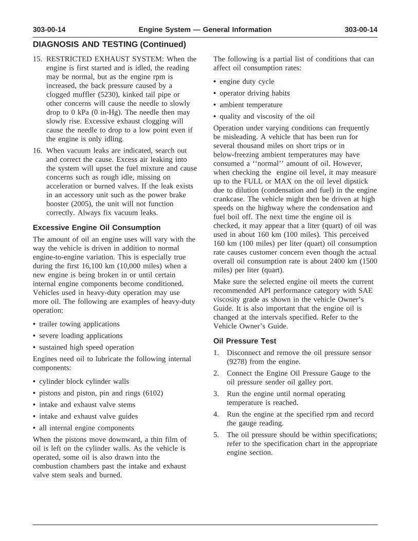
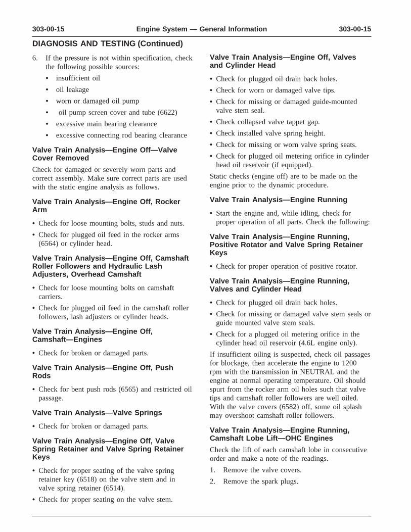
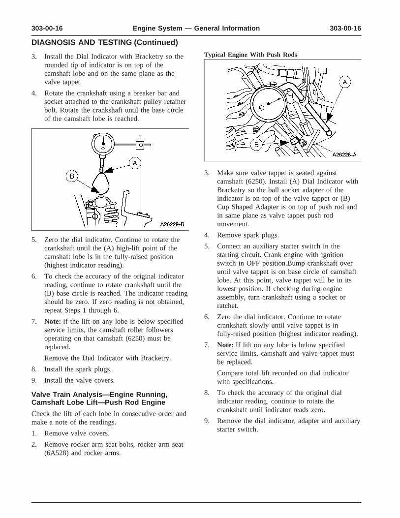
Typical Engine With Push Rods 3. Install the Dial Indicator with Bracketry so therounded tip of indicator is on top of thecamshaft lobe and on the same plane as thevalve tappet.
4. Rotate the crankshaft using a breaker bar andsocket attached to the crankshaft pulley retainerbolt. Rotate the crankshaft until the base circleof the camshaft lobe is reached.
3. Make sure valve tappet is seated againstcamshaft (6250). Install (A) Dial Indicator withBracketry so the ball socket adapter of theindicator is on top of the valve tappet or (B)Cup Shaped Adapter is on top of push rod andin same plane as valve tappet push rodmovement.
4. Remove spark plugs.5. Zero the dial indicator. Continue to rotate the
5. Connect an auxiliary starter switch in thecrankshaft until the (A) high-lift point of thestarting circuit. Crank engine with ignitioncamshaft lobe is in the fully-raised positionswitch in OFF position.Bump crankshaft over(highest indicator reading).until valve tappet is on base circle of camshaft
6. To check the accuracy of the original indicator lobe. At this point, valve tappet will be in itsreading, continue to rotate crankshaft until the lowest position. If checking during engine(B) base circle is reached. The indicator reading assembly, turn crankshaft using a socket orshould be zero. If zero reading is not obtained, ratchet.repeat Steps 1 through 6.
6. Zero the dial indicator. Continue to rotate7. Note: If the lift on any lobe is below specified crankshaft slowly until valve tappet is in
service limits, the camshaft roller followers fully-raised position (highest indicator reading).operating on that camshaft (6250) must be
7. Note: If lift on any lobe is below specifiedreplaced. service limits, camshaft and valve tappet must
Remove the Dial Indicator with Bracketry. be replaced. 8. Install the spark plugs. Compare total lift recorded on dial indicator9. Install the valve covers. with specifications.
8. To check the accuracy of the original dialValve Train Analysis—Engine Running,indicator reading, continue to rotate theCamshaft Lobe Lift—Push Rod Enginecrankshaft until indicator reads zero.Check the lift of each lobe in consecutive order and
9. Remove the dial indicator, adapter and auxiliarymake a note of the readings.starter switch.1. Remove valve covers.
2. Remove rocker arm seat bolts, rocker arm seat(6A528) and rocker arms.
303-00-17 303-00-17Engine System — General Information
DIAGNOSIS AND TESTING (Continued)
A sticking valve tappet plunger can be caused by10. CAUTION: After installing rockercontaminants or varnish inside the valve tappet.arms, do not rotate crankshaft until valve
tappets have had sufficient time to bleed A valve tappet check valve that is not functioningdown. To do otherwise may cause serious can be caused by an obstruction such as dirt orvalve damage. Manually bleeding-down valve chips that prevent it from closing when the camshafttappets will reduce waiting time. lobe is lifting the valve tappet. It may also be
caused by a broken check valve spring.Install rocker arm seats, rocker arms and rockerarm seat bolts. Air bubbles in the lubrication system will prevent
the valve tappet from supporting the valve spring11. Install valve covers.load. This can be caused by too high or too low an
12. Install spark plugs. oil level in the oil pan or by air being drawn intothe system through a hole, crack or leaking gasketValve Train Analysis—Engine Running,on the oil pump screen cover and tube.Valve TappetIf the leakdown time is below the specified time forValve tappet noise can be caused by any of theused valve tappets, noisy operation can result. If nofollowing:other cause for noisy valve tappets can be found,
• excessive collapsed valve tappet gap the leakdown rate should be checked and any valve• sticking valve tappet plunger tappets outside the specification should be replaced.
• valve tappet check valve not functioning properly Assembled valve tappets can be tested withHydraulic Tappet Leakdown Tester to check the• air in lubrication system leakdown rate. The leakdown rate specification is
• leakdown rate too rapid the time in seconds for the plunger to move a• excessive valve guide wear specified distance while under a 22.7 kg (50 lb)
load. Test the valve tappets as outlined in thisExcessive collapsed valve tappet gap can be causedsection.by loose rocker arm seat bolts/nuts, incorrect initial
adjustment or wear of valve tappet face, or wornroller valve tappets, push rod (6565), rocker arm(6564), rocker arm seat or valve tip. With valvetappet collapsed, check gap between the valve tipand the rocker arm to determine if any other valvetrain parts are damaged, worn or out of adjustment.
303-00-18 303-00-18Engine System — General Information
GENERAL PROCEDURES
Sprockets
1. WARNING: To avoid the possibility ofpersonal injury or damage to the vehicle, donot operate the engine with the hood openuntil the fan blade has been examined forpossible cracks and separation.
Note: Specifications show the expectedminimum or maximum condition.
Note: If a component fails to meet thespecifications, it is necessary to replace orrefinish. If the component can be refinished,wear limits are provided as an aid to making adecision. Any component that fails to meetspecifications and cannot be refinished must bereplaced.
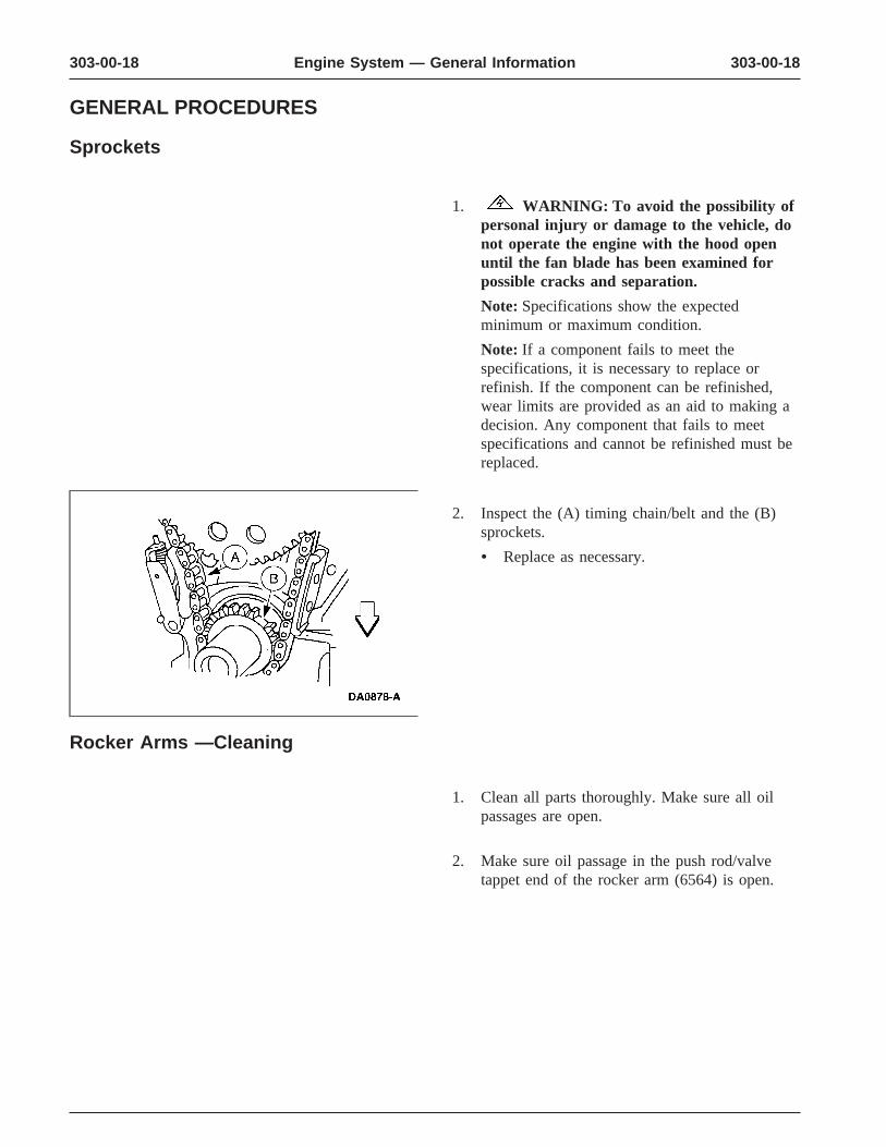
2. Inspect the (A) timing chain/belt and the (B)sprockets.
• Replace as necessary.
Rocker Arms —Cleaning
1. Clean all parts thoroughly. Make sure all oilpassages are open.
2. Make sure oil passage in the push rod/valvetappet end of the rocker arm (6564) is open.
303-00-19 303-00-19Engine System — General Information
GENERAL PROCEDURES (Continued)
Rocker Arms —Inspection
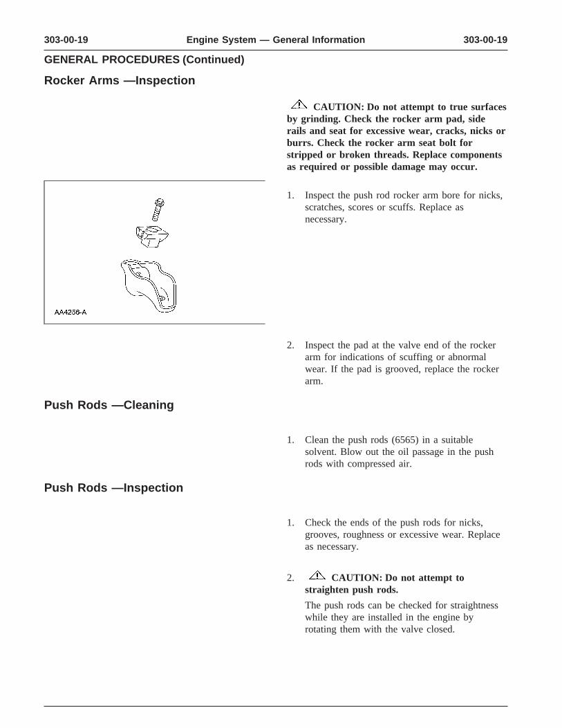
CAUTION: Do not attempt to true surfacesby grinding. Check the rocker arm pad, siderails and seat for excessive wear, cracks, nicks orburrs. Check the rocker arm seat bolt forstripped or broken threads. Replace componentsas required or possible damage may occur.
1. Inspect the push rod rocker arm bore for nicks,scratches, scores or scuffs. Replace asnecessary.
2. Inspect the pad at the valve end of the rockerarm for indications of scuffing or abnormalwear. If the pad is grooved, replace the rockerarm.
Push Rods —Cleaning
1. Clean the push rods (6565) in a suitablesolvent. Blow out the oil passage in the pushrods with compressed air.
Push Rods —Inspection
1. Check the ends of the push rods for nicks,grooves, roughness or excessive wear. Replaceas necessary.
2. CAUTION: Do not attempt tostraighten push rods.
The push rods can be checked for straightnesswhile they are installed in the engine byrotating them with the valve closed.
303-00-20 303-00-20Engine System — General Information
GENERAL PROCEDURES (Continued)
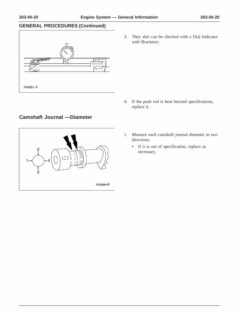
3. They also can be checked with a Dial Indicatorwith Bracketry.
4. If the push rod is bent beyond specifications,replace it.
Camshaft Journal —Diameter
1. Measure each camshaft journal diameter in twodirections.
• If it is out of specification, replace asnecessary.
303-00-21 303-00-21Engine System — General Information
GENERAL PROCEDURES (Continued)
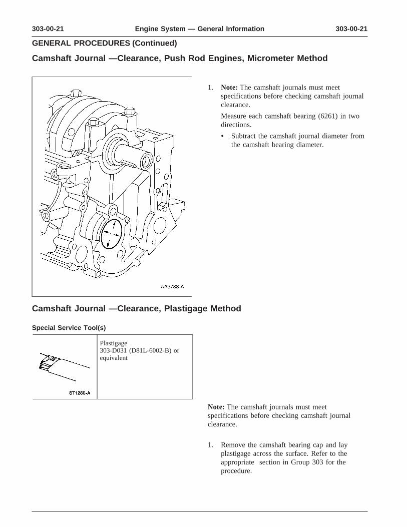
Camshaft Journal —Clearance, Push Rod Engines, Micrometer Method
1. Note: The camshaft journals must meetspecifications before checking camshaft journalclearance.
Measure each camshaft bearing (6261) in twodirections.
• Subtract the camshaft journal diameter fromthe camshaft bearing diameter.
Camshaft Journal —Clearance, Plastigage Method
Special Service Tool(s)
Plastigage303-D031 (D81L-6002-B) orequivalent
Note: The camshaft journals must meetspecifications before checking camshaft journalclearance.
1. Remove the camshaft bearing cap and layplastigage across the surface. Refer to theappropriate section in Group 303 for theprocedure.
303-00-22 303-00-22Engine System — General Information
GENERAL PROCEDURES (Continued)
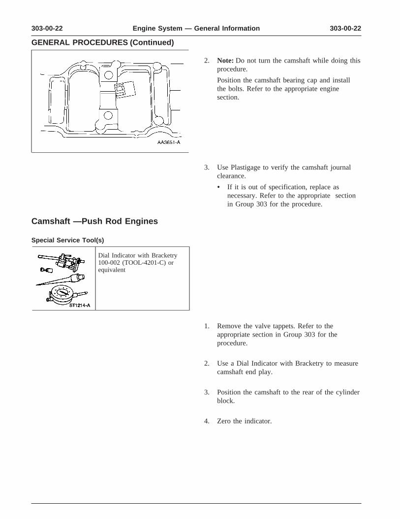
2. Note: Do not turn the camshaft while doing thisprocedure.
Position the camshaft bearing cap and installthe bolts. Refer to the appropriate enginesection.
3. Use Plastigage to verify the camshaft journalclearance.
• If it is out of specification, replace asnecessary. Refer to the appropriate sectionin Group 303 for the procedure.
Camshaft —Push Rod Engines
Special Service Tool(s)
Dial Indicator with Bracketry100-002 (TOOL-4201-C) orequivalent
1. Remove the valve tappets. Refer to theappropriate section in Group 303 for theprocedure.
2. Use a Dial Indicator with Bracketry to measurecamshaft end play.
3. Position the camshaft to the rear of the cylinderblock.
4. Zero the indicator.

303-00-23 303-00-23Engine System — General Information
GENERAL PROCEDURES (Continued)
5. Move the camshaft to the front of the cylinderblock. Note and record the camshaft end play.
• If camshaft end play exceeds specifications,replace the camshaft thrust plate (6269).
Camshaft —End Play, OHC Engines
Special Service Tool(s)
Dial Indicator with Bracketry100-002 (TOOL-4201-C) orequivalent
1. Remove the roller followers. Refer to theappropriate section in Group 303 for theprocedure.
2. Use a Dial Indicator with Bracketry to measurecamshaft end play.
3. Position the camshaft to the rear of the cylinderhead.
4. Zero the indicator.
5. Move the camshaft to the front of the cylinderhead. Note and record the camshaft end play.
• If camshaft end play exceeds specifications,replace the camshaft thrust bearing washers.
303-00-24 303-00-24Engine System — General Information
GENERAL PROCEDURES (Continued)
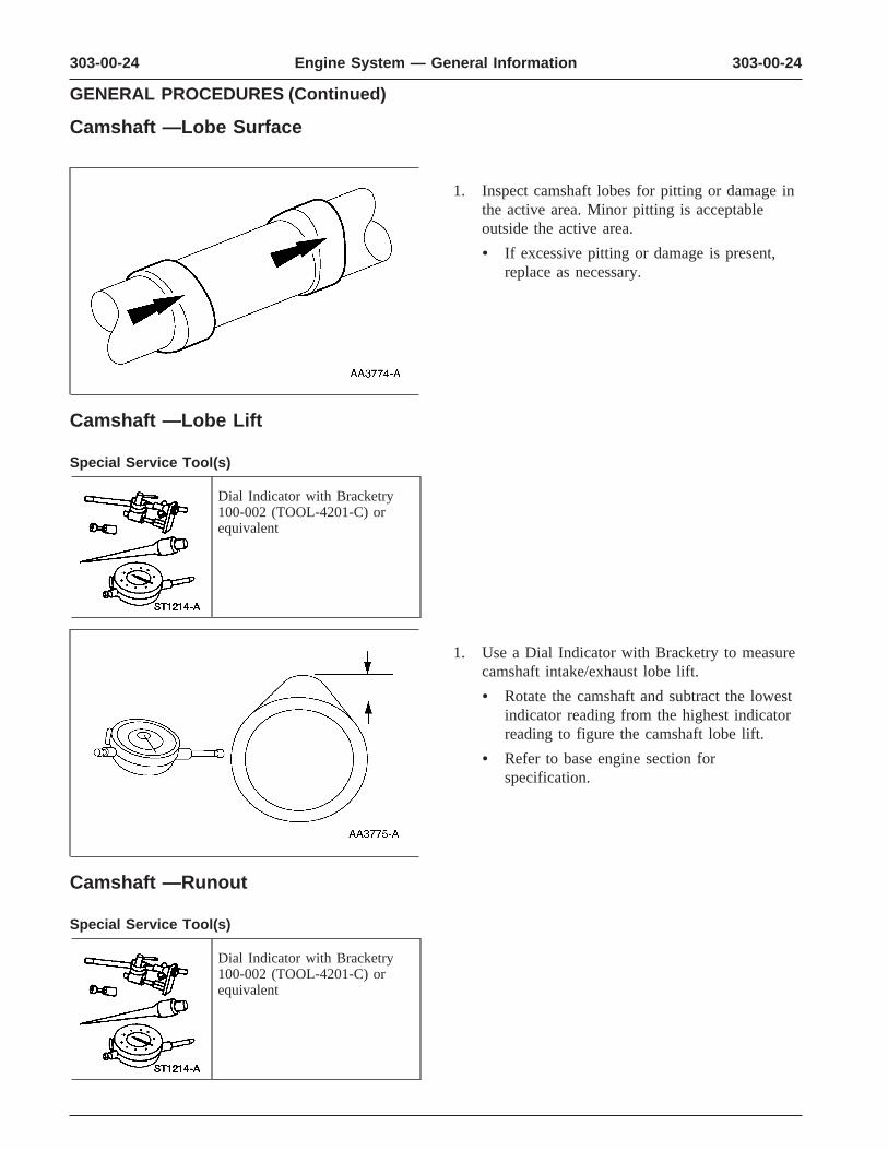
Camshaft —Lobe Surface
1. Inspect camshaft lobes for pitting or damage inthe active area. Minor pitting is acceptableoutside the active area.
• If excessive pitting or damage is present,replace as necessary.
Camshaft —Lobe Lift
Special Service Tool(s)
Dial Indicator with Bracketry100-002 (TOOL-4201-C) orequivalent
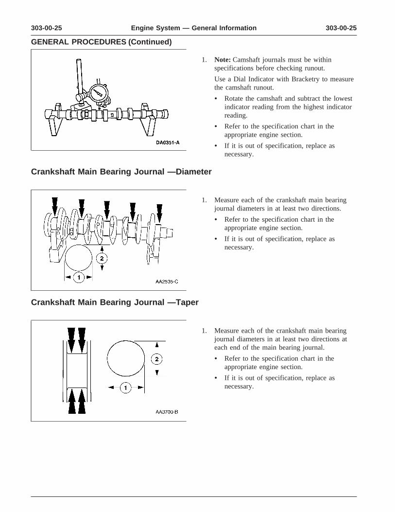
1. Use a Dial Indicator with Bracketry to measurecamshaft intake/exhaust lobe lift.
• Rotate the camshaft and subtract the lowestindicator reading from the highest indicatorreading to figure the camshaft lobe lift.
• Refer to base engine section forspecification.
Camshaft —Runout
Special Service Tool(s)
Dial Indicator with Bracketry100-002 (TOOL-4201-C) orequivalent
303-00-25 303-00-25Engine System — General Information
GENERAL PROCEDURES (Continued)
1. Note: Camshaft journals must be withinspecifications before checking runout.
Use a Dial Indicator with Bracketry to measurethe camshaft runout.
• Rotate the camshaft and subtract the lowestindicator reading from the highest indicatorreading.
• Refer to the specification chart in theappropriate engine section.
• If it is out of specification, replace asnecessary.
Crankshaft Main Bearing Journal —Diameter
1. Measure each of the crankshaft main bearingjournal diameters in at least two directions.
• Refer to the specification chart in theappropriate engine section.
• If it is out of specification, replace asnecessary.
Crankshaft Main Bearing Journal —Taper
1. Measure each of the crankshaft main bearingjournal diameters in at least two directions ateach end of the main bearing journal.
• Refer to the specification chart in theappropriate engine section.
• If it is out of specification, replace asnecessary.
303-00-26 303-00-26Engine System — General Information
GENERAL PROCEDURES (Continued)
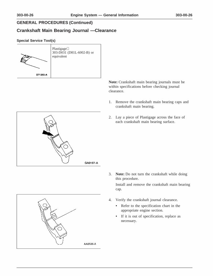
Crankshaft Main Bearing Journal —Clearance
Special Service Tool(s)
Plastigage303-D031 (D81L-6002-B) orequivalent
Note: Crankshaft main bearing journals must bewithin specifications before checking journalclearance.
1. Remove the crankshaft main bearing caps andcrankshaft main bearing.
2. Lay a piece of Plastigage across the face ofeach crankshaft main bearing surface.
3. Note: Do not turn the crankshaft while doingthis procedure.
Install and remove the crankshaft main bearingcap.
4. Verify the crankshaft journal clearance.
• Refer to the specification chart in theappropriate engine section.
• If it is out of specification, replace asnecessary.
303-00-27 303-00-27Engine System — General Information
GENERAL PROCEDURES (Continued)
Crankshaft —End Play
Special Service Tool(s)
Dial Indicator with Bracketry100-002 (TOOL-4201-C) orequivalent
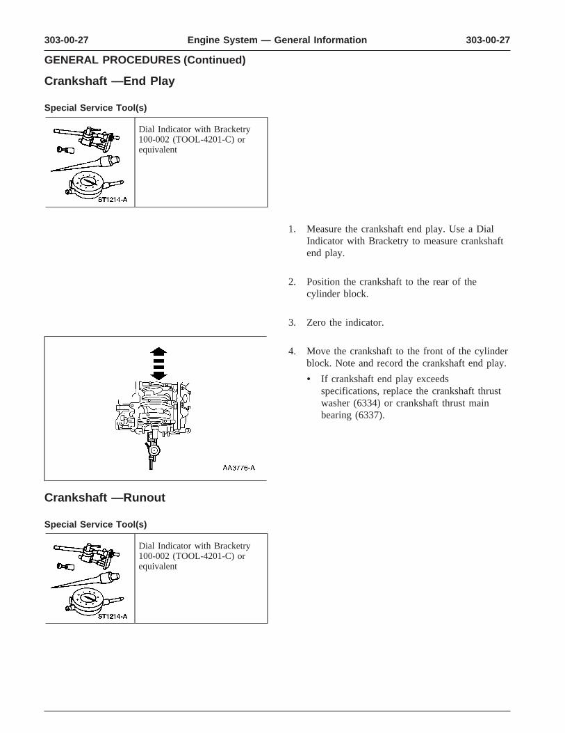
1. Measure the crankshaft end play. Use a DialIndicator with Bracketry to measure crankshaftend play.
2. Position the crankshaft to the rear of thecylinder block.
3. Zero the indicator.
4. Move the crankshaft to the front of the cylinderblock. Note and record the crankshaft end play.
• If crankshaft end play exceedsspecifications, replace the crankshaft thrustwasher (6334) or crankshaft thrust mainbearing (6337).
Crankshaft —Runout
Special Service Tool(s)
Dial Indicator with Bracketry100-002 (TOOL-4201-C) orequivalent
303-00-28 303-00-28Engine System — General Information
GENERAL PROCEDURES (Continued)
1. Note: Crankshaft main bearing journals must bewithin specifications before checking runout.
Use the Dial Indicator with Bracketry tomeasure the crankshaft runout.
• Refer to the Specification chart in theappropriate engine section. Rotate thecrankshaft and subtract the lowest dialindicator reading from the highest dialindicator reading to figure the crankshaftrunout. If it is out of specification, replaceas necessary.
Crankshaft —Connecting Rod Journal Taper, Out of Round
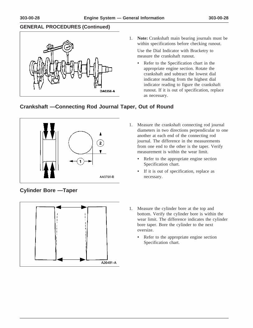
1. Measure the crankshaft connecting rod journaldiameters in two directions perpendicular to oneanother at each end of the connecting rodjournal. The difference in the measurementsfrom one end to the other is the taper. Verifymeasurement is within the wear limit.
• Refer to the appropriate engine sectionSpecification chart.
• If it is out of specification, replace asnecessary.
Cylinder Bore —Taper
1. Measure the cylinder bore at the top andbottom. Verify the cylinder bore is within thewear limit. The difference indicates the cylinderbore taper. Bore the cylinder to the nextoversize.
• Refer to the appropriate engine sectionSpecification chart.

303-00-29 303-00-29Engine System — General Information
GENERAL PROCEDURES (Continued)
Cylinder Bore —Out-of-Round
1. Measure the cylinder bore in two directions.The difference is the out-of-round. Verify theout-of-round is within the wear limit and borethe cylinder to the next oversize limit.
• Refer to the appropriate engine sectionSpecification Chart.
Piston —Inspection
Special Service Tool(s)
Piston Ring Groove Cleaner303-D033 (D81L-6002-D) orequivalent
CAUTION: Do not use a caustic cleaningsolution or a wire brush to clean the pistons ordamage can occur.
1. Clean and inspect the (A) ring lands, (B) skirts,(C) pin bosses, and the (D) tops of the pistons.If wear marks, scores or glazing is found on thepiston skirt, check for a bent or twistedconnecting rod.
303-00-30 303-00-30Engine System — General Information
GENERAL PROCEDURES (Continued)
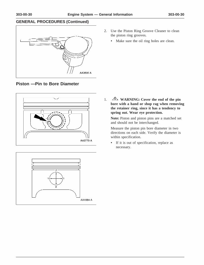
2. Use the Piston Ring Groove Cleaner to cleanthe piston ring grooves.
• Make sure the oil ring holes are clean.
Piston —Pin to Bore Diameter
1. WARNING: Cover the end of the pinbore with a hand or shop rag when removingthe retainer ring, since it has a tendency tospring out. Wear eye protection.
Note: Piston and piston pins are a matched setand should not be interchanged.
Measure the piston pin bore diameter in twodirections on each side. Verify the diameter iswithin specification.
• If it is out of specification, replace asnecessary.
303-00-31 303-00-31Engine System — General Information
GENERAL PROCEDURES (Continued)
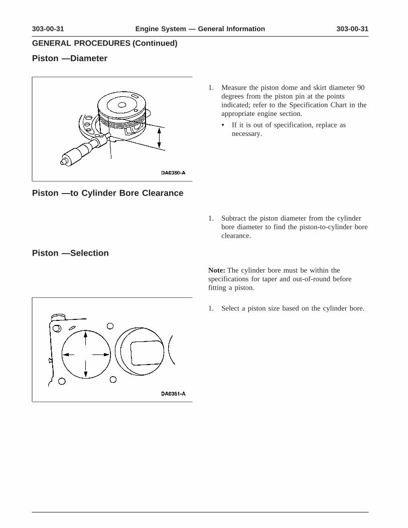
Piston —Diameter
1. Measure the piston dome and skirt diameter 90degrees from the piston pin at the pointsindicated; refer to the Specification Chart in theappropriate engine section.
• If it is out of specification, replace asnecessary.
Piston —to Cylinder Bore Clearance
1. Subtract the piston diameter from the cylinderbore diameter to find the piston-to-cylinder boreclearance.
Piston —Selection
Note: The cylinder bore must be within thespecifications for taper and out-of-round beforefitting a piston.
1. Select a piston size based on the cylinder bore.
303-00-32 303-00-32Engine System — General Information
GENERAL PROCEDURES (Continued)
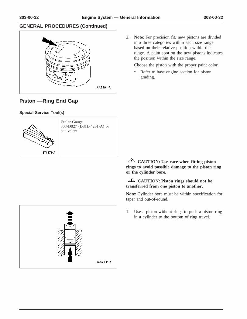
2. Note: For precision fit, new pistons are dividedinto three categories within each size rangebased on their relative position within therange. A paint spot on the new pistons indicatesthe position within the size range.
Choose the piston with the proper paint color.
• Refer to base engine section for pistongrading.
Piston —Ring End Gap
Special Service Tool(s)
Feeler Gauge303-D027 (D81L-4201-A) orequivalent
CAUTION: Use care when fitting pistonrings to avoid possible damage to the piston ringor the cylinder bore.
CAUTION: Piston rings should not betransferred from one piston to another.
Note: Cylinder bore must be within specification fortaper and out-of-round.
1. Use a piston without rings to push a piston ringin a cylinder to the bottom of ring travel.
303-00-33 303-00-33Engine System — General Information
GENERAL PROCEDURES (Continued)
2. Use a feeler gauge to measure the top pistonring end gap and the second piston ring endgap.
• Refer to the appropriate engine sectionSpecification chart.
Piston —Ring-to-Groove Clearance
Special Service Tool(s)
Feeler Gauge303-D027 (D81L-4201-A) orequivalent
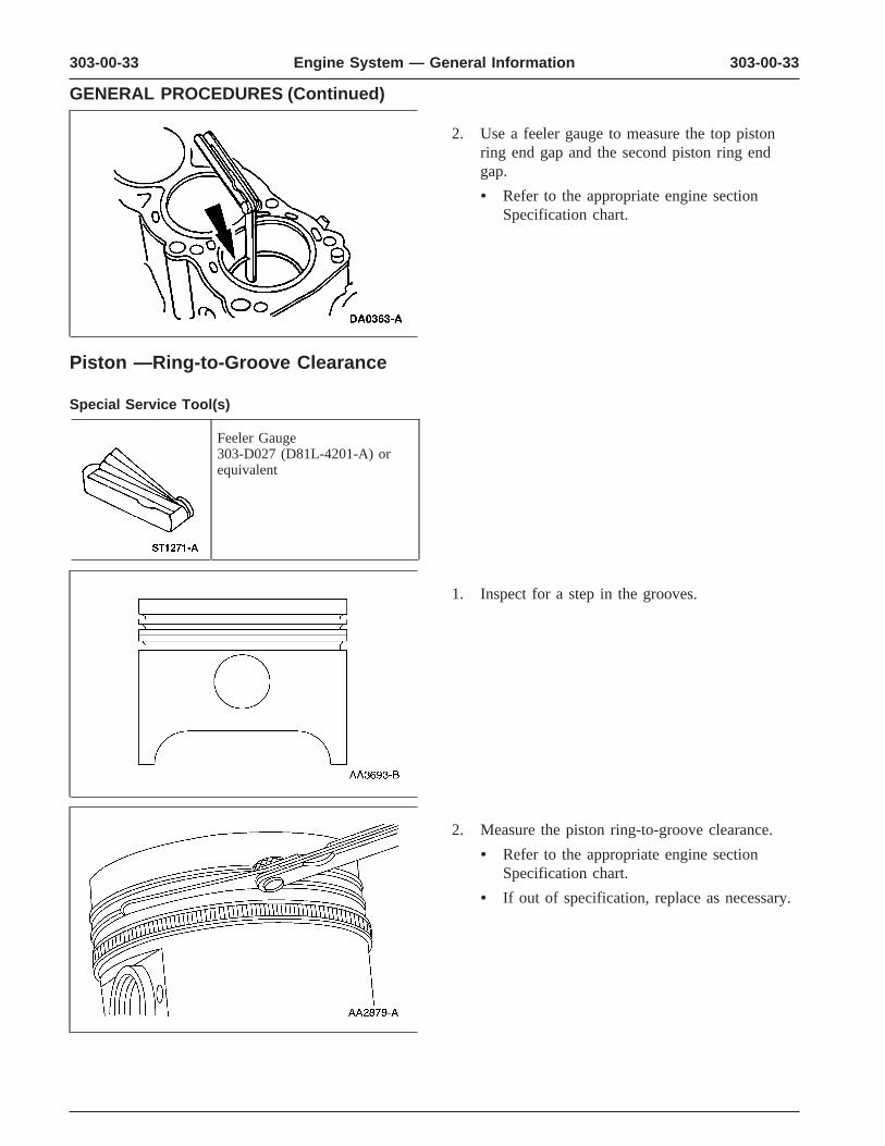
1. Inspect for a step in the grooves.
2. Measure the piston ring-to-groove clearance.
• Refer to the appropriate engine sectionSpecification chart.
• If out of specification, replace as necessary.
303-00-34 303-00-34Engine System — General Information
GENERAL PROCEDURES (Continued)
Piston —Pin Diameter
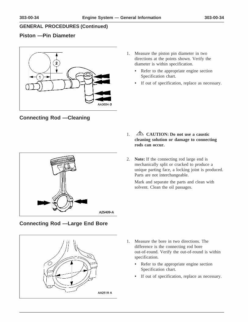
1. Measure the piston pin diameter in twodirections at the points shown. Verify thediameter is within specification.
• Refer to the appropriate engine sectionSpecification chart.
• If out of specification, replace as necessary.
Connecting Rod —Cleaning
1. CAUTION: Do not use a causticcleaning solution or damage to connectingrods can occur.
2. Note: If the connecting rod large end ismechanically split or cracked to produce aunique parting face, a locking joint is produced.Parts are not interchangeable.
Mark and separate the parts and clean withsolvent. Clean the oil passages.
Connecting Rod —Large End Bore
1. Measure the bore in two directions. Thedifference is the connecting rod boreout-of-round. Verify the out-of-round is withinspecification.
• Refer to the appropriate engine sectionSpecification chart.
• If out of specification, replace as necessary.

303-00-35 303-00-35Engine System — General Information
GENERAL PROCEDURES (Continued)
Connecting Rod —Bushing Diameter
1. Measure the inner diameter of the connectingrod bushing, if equipped. Verify the diameter iswithin specification.
• Refer to the appropriate engine sectionSpecification chart.
• If out of specification, replace as necessary.
Connecting Rod —Bend
1. Measure the connecting rod bend on a suitablealignment fixture. Follow the instructions of thefixture manufacturer. Verify the bendmeasurement is within specification.
• Refer to the appropriate engine sectionSpecification chart.
• If out of specification, replace as necessary.
Connecting Rod —Twist
1. Measure the connecting rod twist on a suitablealignment fixture. Follow the instructions of thefixture manufacturer. Verify the measurement iswithin specification.
• Refer to the appropriate engine sectionSpecification chart.
• If out of specification, replace as necessary.
303-00-36 303-00-36Engine System — General Information
GENERAL PROCEDURES (Continued)
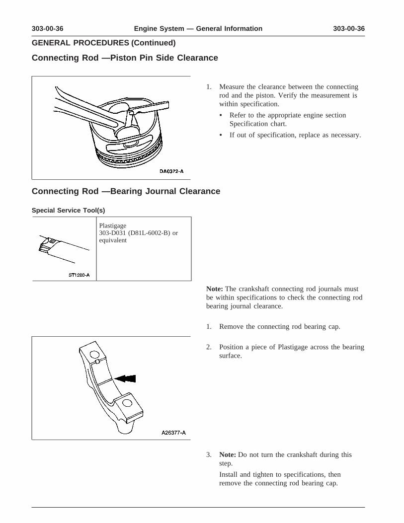
Connecting Rod —Piston Pin Side Clearance
1. Measure the clearance between the connectingrod and the piston. Verify the measurement iswithin specification.
• Refer to the appropriate engine sectionSpecification chart.
• If out of specification, replace as necessary.
Connecting Rod —Bearing Journal Clearance
Special Service Tool(s)
Plastigage303-D031 (D81L-6002-B) orequivalent
Note: The crankshaft connecting rod journals mustbe within specifications to check the connecting rodbearing journal clearance.
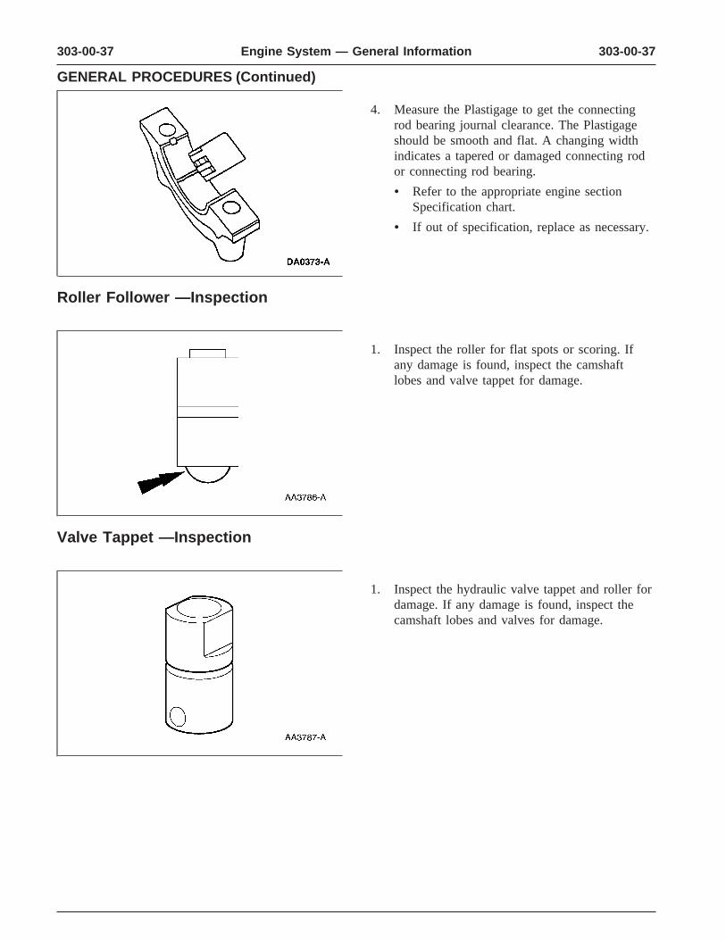
1. Remove the connecting rod bearing cap.
2. Position a piece of Plastigage across the bearingsurface.
3. Note: Do not turn the crankshaft during thisstep.
Install and tighten to specifications, thenremove the connecting rod bearing cap.
303-00-37 303-00-37Engine System — General Information
GENERAL PROCEDURES (Continued)
4. Measure the Plastigage to get the connectingrod bearing journal clearance. The Plastigageshould be smooth and flat. A changing widthindicates a tapered or damaged connecting rodor connecting rod bearing.
• Refer to the appropriate engine sectionSpecification chart.
• If out of specification, replace as necessary.
Roller Follower —Inspection
1. Inspect the roller for flat spots or scoring. Ifany damage is found, inspect the camshaftlobes and valve tappet for damage.
Valve Tappet —Inspection
1. Inspect the hydraulic valve tappet and roller fordamage. If any damage is found, inspect thecamshaft lobes and valves for damage.

303-00-38 303-00-38Engine System — General Information
GENERAL PROCEDURES (Continued)
Valve Tappet —Leakdown Test, Hydraulic
1. Note: The leakdown test will not be accurate ifit is done with engine oil in the hydraulic valvetappet. Use testing fluid. New hydraulic valvetappets are already filled with testing fluid.
Compress the hydraulic valve tappet to removethe engine oil if necessary.
2. Place the (A) hydraulic valve tappet in a (B)commercially available hydraulic tappetleakdown tester. Position the (C) steel ballprovided in the plunger cap. Add testing fluidto cover the hydraulic valve tappet andcompress hydraulic tappet leakdown tester untilthe hydraulic valve tappet is filled with testingfluid.
3. Adjust the length of the (A) ram so the (B)pointer is just below the (C) Start Timing markwhen the ram contacts the hydraulic valvetappet. Start timing as the pointer passes the (C)Start Timing mark and end timing as thepointer reaches the (D) center mark. Refer tothe appropriate engine section in Group 303 forspecifications on time parameters.
Valve —Stem Diameter
1. Measure the diameter of each intake andexhaust valve stem at the points shown. Verifythe diameter is within specification.
• Refer to the appropriate engine sectionSpecification chart.
• If out of specification, replace as necessary.
303-00-39 303-00-39Engine System — General Information
GENERAL PROCEDURES (Continued)
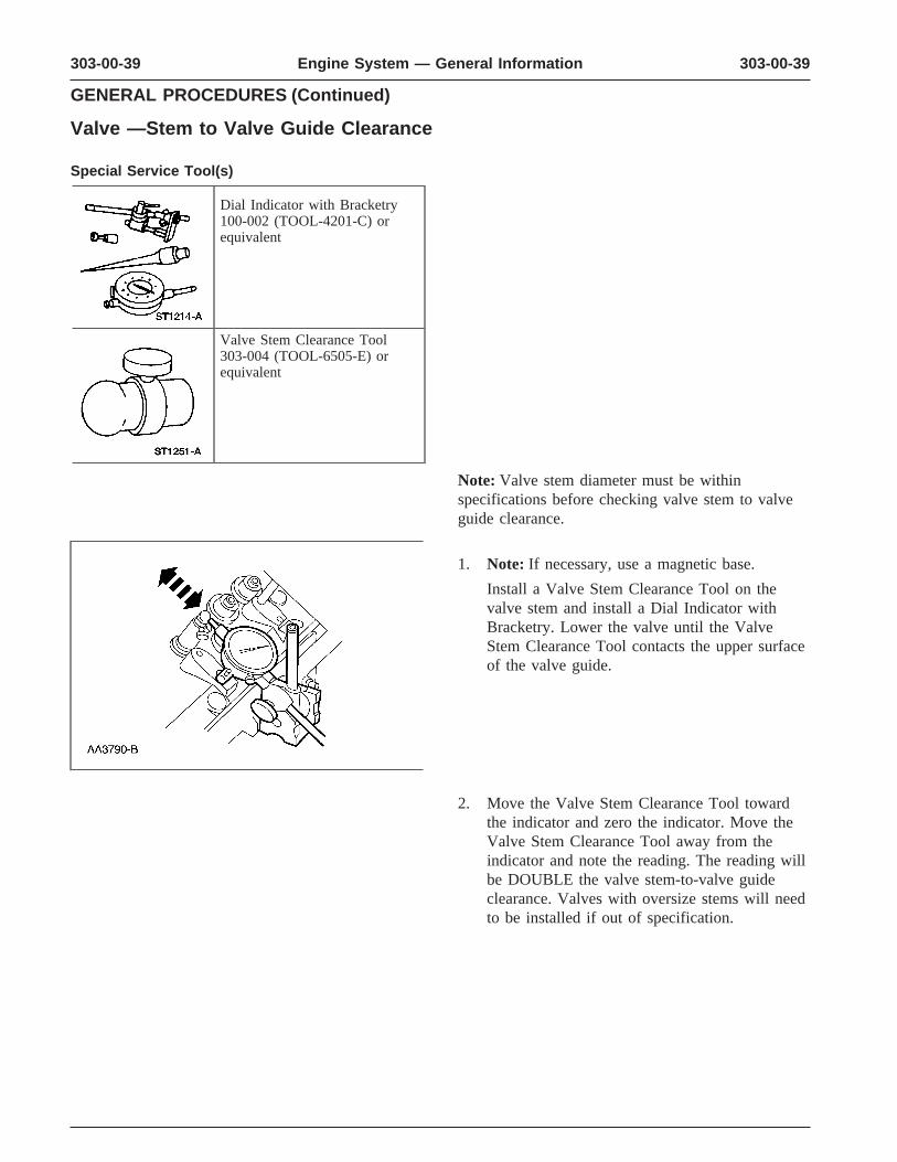
Valve —Stem to Valve Guide Clearance
Special Service Tool(s)
Dial Indicator with Bracketry100-002 (TOOL-4201-C) orequivalent
Valve Stem Clearance Tool303-004 (TOOL-6505-E) orequivalent
Note: Valve stem diameter must be withinspecifications before checking valve stem to valveguide clearance.
1. Note: If necessary, use a magnetic base.
Install a Valve Stem Clearance Tool on thevalve stem and install a Dial Indicator withBracketry. Lower the valve until the ValveStem Clearance Tool contacts the upper surfaceof the valve guide.
2. Move the Valve Stem Clearance Tool towardthe indicator and zero the indicator. Move theValve Stem Clearance Tool away from theindicator and note the reading. The reading willbe DOUBLE the valve stem-to-valve guideclearance. Valves with oversize stems will needto be installed if out of specification.

303-00-40 303-00-40Engine System — General Information
GENERAL PROCEDURES (Continued)
Valve —Inspection
1. Inspect the following valve areas:
1 the end of the stem for grooves or scoring
2 the valve face and the edge for pits, groovesor scores
3 the valve head for signs of burning, erosion,warpage and cracking.
4 the valve head thickness for wear
Valve —Guide Inner Diameter
1. Measure the inner diameter of the valve guidesin two directions where indicated.
• Refer to the appropriate engine sectionSpecification chart.
2. If the valve guide is not within specifications,ream the valve guide and install a valve with anoversize stem or remove the valve guide andinstall a new valve guide.
Valve —Guide Reaming
1. Use a hand-reaming kit to ream the valveguide.
303-00-41 303-00-41Engine System — General Information
GENERAL PROCEDURES (Continued)
2. Reface the valve seat.
3. Clean the sharp edges left by reaming.
Valve —Spring Installed Length
1. Measure the installed length of each valvespring.
• Refer to the specification chart in theappropriate engine section.
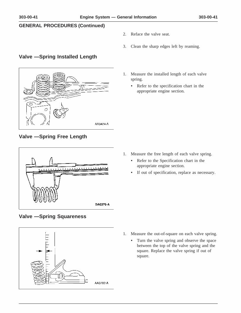
Valve —Spring Free Length
1. Measure the free length of each valve spring.
• Refer to the Specification chart in theappropriate engine section.
• If out of specification, replace as necessary.
Valve —Spring Squareness
1. Measure the out-of-square on each valve spring.
• Turn the valve spring and observe the spacebetween the top of the valve spring and thesquare. Replace the valve spring if out ofsquare.
303-00-42 303-00-42Engine System — General Information
GENERAL PROCEDURES (Continued)
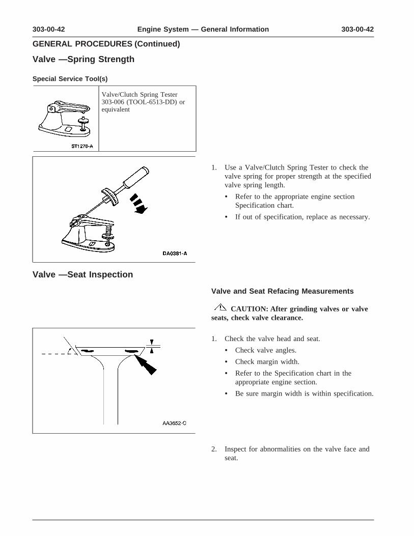
Valve —Spring Strength
Special Service Tool(s)
Valve/Clutch Spring Tester303-006 (TOOL-6513-DD) orequivalent
1. Use a Valve/Clutch Spring Tester to check thevalve spring for proper strength at the specifiedvalve spring length.
• Refer to the appropriate engine sectionSpecification chart.
• If out of specification, replace as necessary.
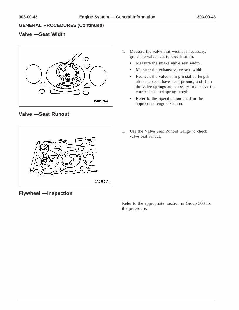
Valve —Seat Inspection
Valve and Seat Refacing Measurements
CAUTION: After grinding valves or valveseats, check valve clearance.
1. Check the valve head and seat.
• Check valve angles.
• Check margin width.
• Refer to the Specification chart in theappropriate engine section.
• Be sure margin width is within specification.
2. Inspect for abnormalities on the valve face andseat.
303-00-43 303-00-43Engine System — General Information
GENERAL PROCEDURES (Continued)
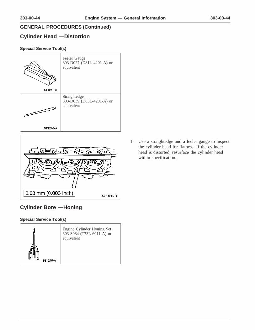
Valve —Seat Width
1. Measure the valve seat width. If necessary,grind the valve seat to specification.
• Measure the intake valve seat width.
• Measure the exhaust valve seat width.
• Recheck the valve spring installed lengthafter the seats have been ground, and shimthe valve springs as necessary to achieve thecorrect installed spring length.
• Refer to the Specification chart in theappropriate engine section.
Valve —Seat Runout
1. Use the Valve Seat Runout Gauge to checkvalve seat runout.
Flywheel —Inspection
Refer to the appropriate section in Group 303 forthe procedure.
303-00-44 303-00-44Engine System — General Information
GENERAL PROCEDURES (Continued)
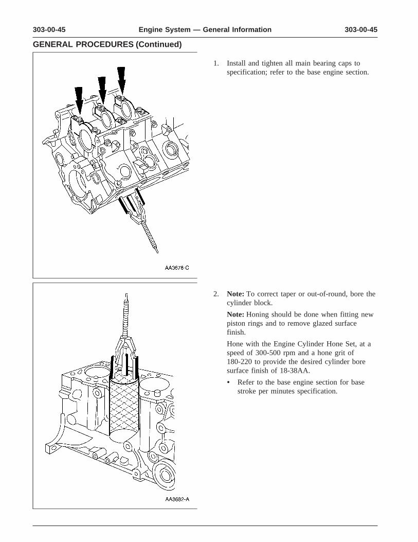
Cylinder Head —Distortion
Special Service Tool(s)
Feeler Gauge303-D027 (D81L-4201-A) orequivalent
Straightedge303-D039 (D83L-4201-A) orequivalent
1. Use a straightedge and a feeler gauge to inspectthe cylinder head for flatness. If the cylinderhead is distorted, resurface the cylinder headwithin specification.
Cylinder Bore —Honing
Special Service Tool(s)
Engine Cylinder Honing Set303-S084 (T73L-6011-A) orequivalent
303-00-45 303-00-45Engine System — General Information
GENERAL PROCEDURES (Continued)
1. Install and tighten all main bearing caps tospecification; refer to the base engine section.
2. Note: To correct taper or out-of-round, bore thecylinder block.
Note: Honing should be done when fitting newpiston rings and to remove glazed surfacefinish.
Hone with the Engine Cylinder Hone Set, at aspeed of 300-500 rpm and a hone grit of180-220 to provide the desired cylinder boresurface finish of 18-38AA.
• Refer to the base engine section for basestroke per minutes specification.
303-00-46 303-00-46Engine System — General Information
GENERAL PROCEDURES (Continued)
Cylinder Bore —Cleaning
1. CAUTION: If these procedures are notfollowed, rusting of the cylinder bores mayoccur.
Clean the cylinder bores with soap or detergentand water.
2. Thoroughly rinse with clean water and wipe drywith a clean, lint-free cloth.
3. Use a clean, lint-free cloth and lubricate thecylinder bores.
• Use Super Premium SAE 5W30XO-5W30-QSP or equivalent meeting Fordspecification WSS-M2C153-G.
Cylinder Block —Distortion
Special Service Tool(s)
Feeler Gauge303-D027 (D81L-4201-A) orequivalent
Straightedge303-D039 (D83L-4201-A) orequivalent
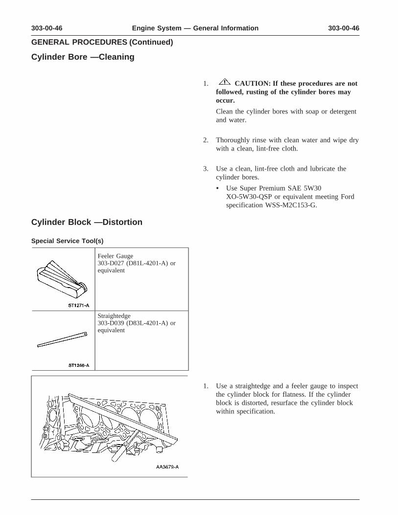
1. Use a straightedge and a feeler gauge to inspectthe cylinder block for flatness. If the cylinderblock is distorted, resurface the cylinder blockwithin specification.
303-00-47 303-00-47Engine System — General Information
GENERAL PROCEDURES (Continued)
Cylinder Block —Core Plug Replacement
Special Service Tool(s)
Impact Slide Hammer100-001 (T50T-100-A)
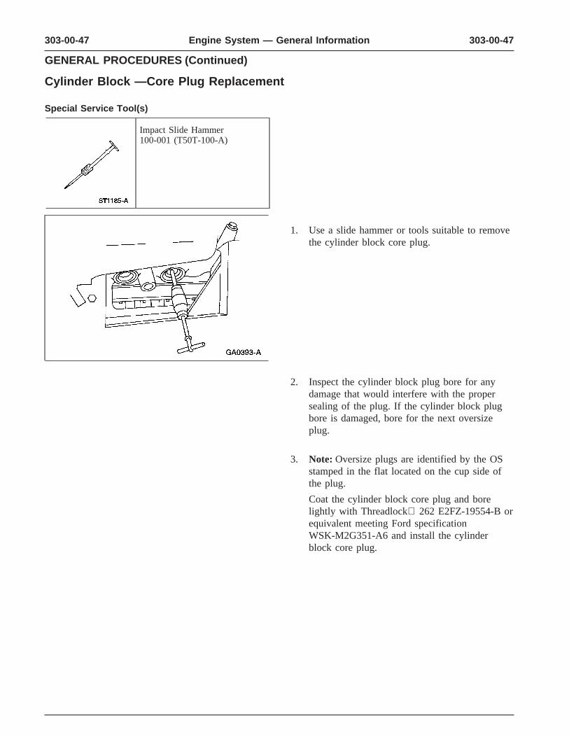
1. Use a slide hammer or tools suitable to removethe cylinder block core plug.
2. Inspect the cylinder block plug bore for anydamage that would interfere with the propersealing of the plug. If the cylinder block plugbore is damaged, bore for the next oversizeplug.
3. Note: Oversize plugs are identified by the OSstamped in the flat located on the cup side ofthe plug.
Coat the cylinder block core plug and borelightly with Threadlock 262 E2FZ-19554-B orequivalent meeting Ford specificationWSK-M2G351-A6 and install the cylinderblock core plug.
303-00-48 303-00-48Engine System — General Information
GENERAL PROCEDURES (Continued)
Cup-Type
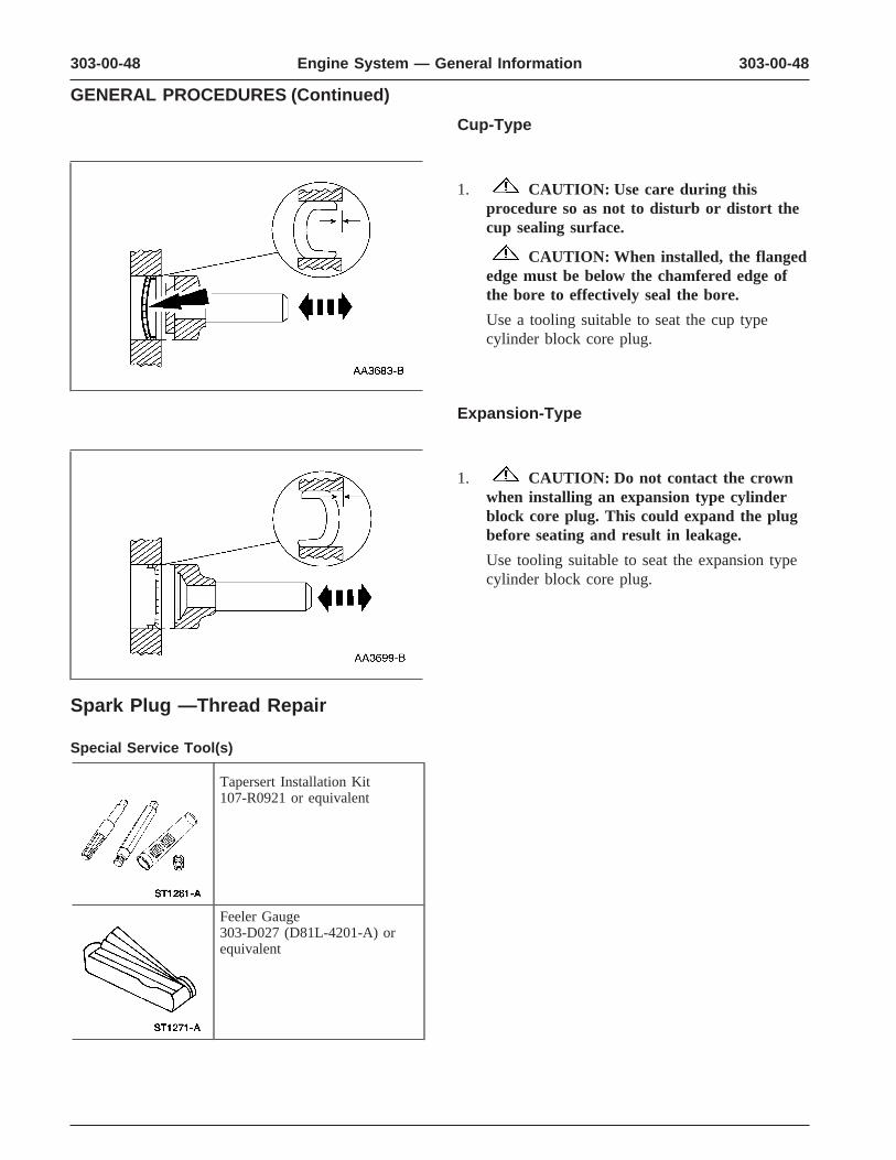
1. CAUTION: Use care during thisprocedure so as not to disturb or distort thecup sealing surface.
CAUTION: When installed, the flangededge must be below the chamfered edge ofthe bore to effectively seal the bore.
Use a tooling suitable to seat the cup typecylinder block core plug.
Expansion-Type
1. CAUTION: Do not contact the crownwhen installing an expansion type cylinderblock core plug. This could expand the plugbefore seating and result in leakage.
Use tooling suitable to seat the expansion typecylinder block core plug.
Spark Plug —Thread Repair
Special Service Tool(s)
Tapersert Installation Kit107-R0921 or equivalent
Feeler Gauge303-D027 (D81L-4201-A) orequivalent
303-00-49 303-00-49Engine System — General Information
GENERAL PROCEDURES (Continued)
CAUTION: The cylinder head must beremoved from the engine before installing atapersert. If this procedure is done with thecylinder head on the engine, the cylinder wallscan be damaged by metal chips produced by thethread cutting process.
CAUTION: Do not use power or air-driventools for installing taperserts.
Note: This repair is permanent and will have noeffect on cylinder head or spark plug life.
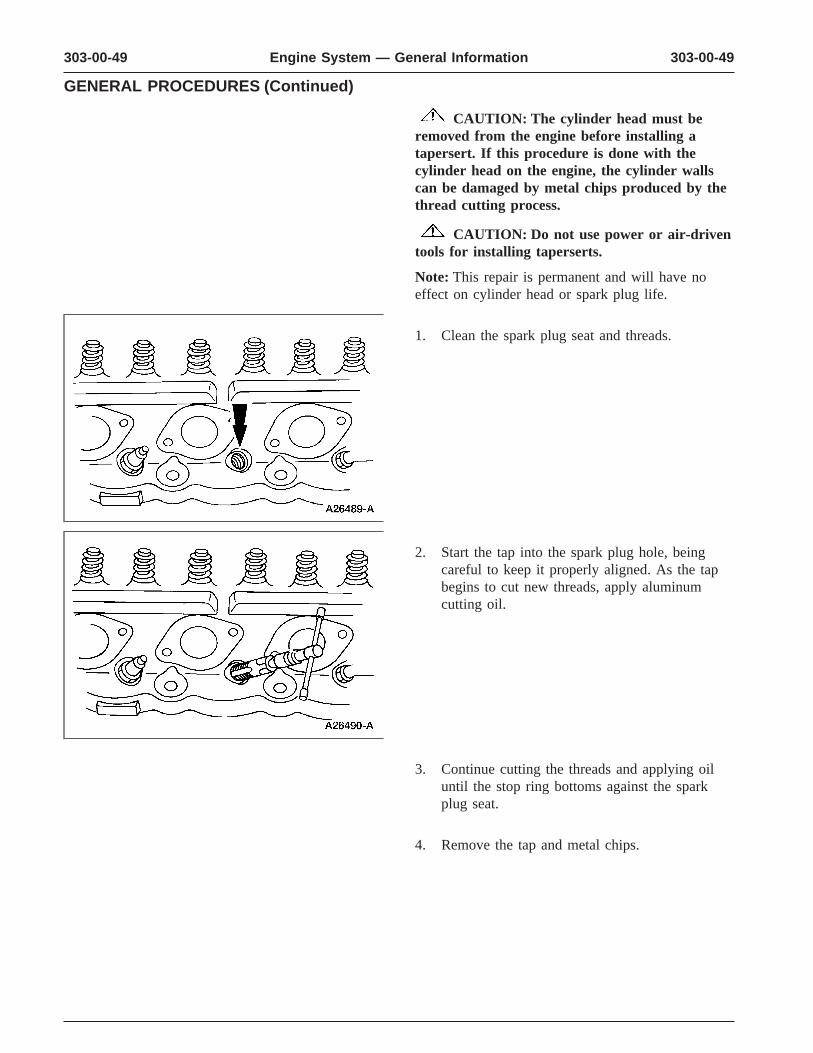
1. Clean the spark plug seat and threads.
2. Start the tap into the spark plug hole, beingcareful to keep it properly aligned. As the tapbegins to cut new threads, apply aluminumcutting oil.
3. Continue cutting the threads and applying oiluntil the stop ring bottoms against the sparkplug seat.
4. Remove the tap and metal chips.
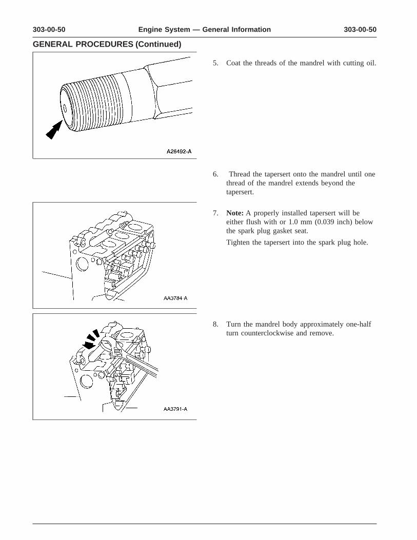
303-00-50 303-00-50Engine System — General Information
GENERAL PROCEDURES (Continued)
5. Coat the threads of the mandrel with cutting oil.
6. Thread the tapersert onto the mandrel until onethread of the mandrel extends beyond thetapersert.
7. Note: A properly installed tapersert will beeither flush with or 1.0 mm (0.039 inch) belowthe spark plug gasket seat.
Tighten the tapersert into the spark plug hole.
8. Turn the mandrel body approximately one-halfturn counterclockwise and remove.
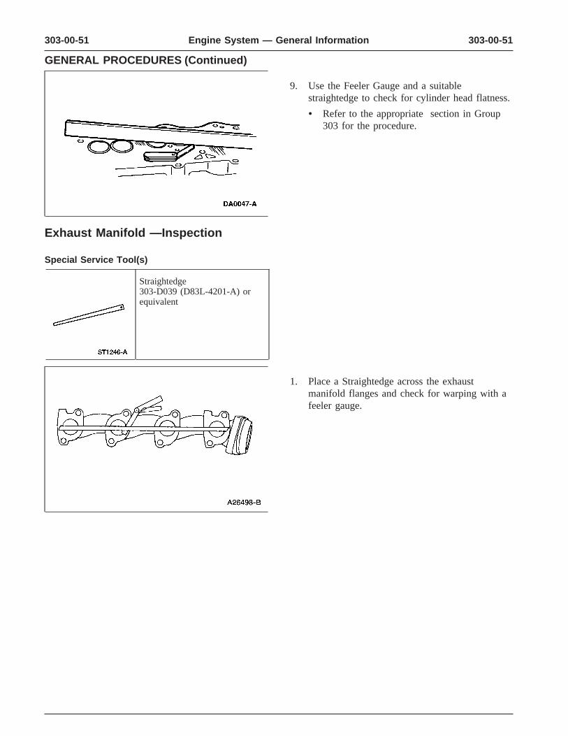
303-00-51 303-00-51Engine System — General Information
GENERAL PROCEDURES (Continued)
9. Use the Feeler Gauge and a suitablestraightedge to check for cylinder head flatness.
• Refer to the appropriate section in Group303 for the procedure.
Exhaust Manifold —Inspection
Special Service Tool(s)
Straightedge303-D039 (D83L-4201-A) orequivalent
1. Place a Straightedge across the exhaustmanifold flanges and check for warping with afeeler gauge.
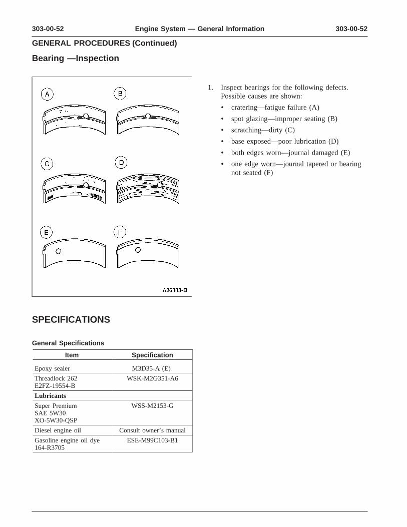
303-00-52 303-00-52Engine System — General Information
GENERAL PROCEDURES (Continued)
Bearing —Inspection
1. Inspect bearings for the following defects.Possible causes are shown:
• cratering—fatigue failure (A)
• spot glazing—improper seating (B)
• scratching—dirty (C)
• base exposed—poor lubrication (D)
• both edges worn—journal damaged (E)
• one edge worn—journal tapered or bearingnot seated (F)
SPECIFICATIONS
General Specifications
Item Specification
Epoxy sealer M3D35-A (E)
Threadlock 262 WSK-M2G351-A6E2FZ-19554-B
Lubricants
Super Premium WSS-M2153-GSAE 5W30XO-5W30-QSP
Diesel engine oil Consult owner’s manual
Gasoline engine oil dye ESE-M99C103-B1164-R3705