Embed Size (px)
Citation preview

Manual 10/12 MN04020005Z-EN
PowerXL™
DA1
Variable Frequency Drives

All brand and product names are trademarks or registered trademarks of the owner concerned.
Emergency On Call ServicePlease call your local representative:http://www.eaton.com/moeller/aftersalesorHotline of the After Sales Service:+49 (0) 180 5 223822 (de, en)[email protected]
Original Operating InstructionsThe German-language edition of this document is the original operating manual.
Translation of the original operating manualAll editions of this document other than those in German language are translations of the original German manual.
1st published 2012, edition date 10/12© 2012 by Eaton Industries GmbH, 53105 Bonn
Production: René WiegandTranslation: globaldocs GmbH
All rights reserved, including those of the translation.
No part of this manual may be reproduced in any form (printed, photocopy, microfilm or any other process) or processed, duplicated or distributed by means of electronic systems without written permission of Eaton Industries GmbH, Bonn.
Subject to alteration without notice.
Rück
en
bre
ite
fest
lege
n!
(1 B
latt
= 0
,10
6 m
m,
gilt
nur
für
XB
S)
(1 B
latt
= 0
,08
0 m
m f
ür
Ebe
rwe
in D
igit
ald
ruck b
ei 80
g/m
2)

I
Before commencing the installation
• Disconnect the power supply of the device.
• Ensure that devices cannot be accidentally restarted.
• Verify isolation from the supply.
• Earth and short circuit the device.
• Cover or enclose any adjacent live components.
• Follow the engineering instructions (AWA/IL) for the device concerned.
• Only suitably qualified personnel in accordance with EN 50110-1/-2 (VDE 0105 Part 100) may work on this device/system.
• Before installation and before touching the device ensure that you are free of electrostatic charge.
• The functional earth (FE, PES) must be connected to the protective earth (PE) or the potential equalisation. The system installer is responsible for implementing this connection.
• Connecting cables and signal lines should be installed so that inductive or capacitive interference does not impair the automation functions.
• Install automation devices and related operating elements in such a way that they are well protected against unintentional operation.
• Suitable safety hardware and software measures should be implemented for the I/O interface so that an open circuit on the signal side does not result in undefined states in the automation devices.
• Ensure a reliable electrical isolation of the extra-low voltage of the 24 V supply. Only use power supply units complying with IEC 60364-4-41 (VDE 0100 Part 410) or HD384.4.41 S2.
• Deviations of the mains voltage from the rated value must not exceed the tolerance limits given in the specifications, otherwise this may cause malfunction and dangerous operation.
• Emergency stop devices complying with IEC/EN 60204-1 must be effective in all operating modes of the automation devices. Unlatching the emergency-stop devices must not cause a restart.
• Devices that are designed for mounting in housings or control cabinets must only be operated and controlled after they have been installed and with the housing closed. Desktop or portable units must only be operated and controlled in enclosed housings.
• Measures should be taken to ensure the proper restart of programs interrupted after a voltage dip or failure. This should not cause dangerous operating states even for a short time. If necessary, emergency-stop devices should be implemented.
• Wherever faults in the automation system may cause injury or material damage, external measures must be implemented to ensure a safe operating state in the event of a fault or malfunction (for example, by means of separate limit switches, mechanical interlocks etc.).
• Depending on their degree of protection, frequency inverters may contain live bright metal parts, moving or rotating components or hot surfaces during and immediately after operation.
• Removal of the required covers, improper installation or incorrect operation of motor or frequency inverter may cause the failure of the device and may lead to serious injury or damage.
• The applicable national accident prevention and safety regulations apply to all work carried on live frequency inverters.
• The electrical installation must be carried out in accordance with the relevant regulations (e. g. with regard to cable cross sections, fuses, PE).
• Transport, installation, commissioning and maintenance work must be carried out only by qualified personnel (IEC 60364, HD 384 and national occupational safety regulations).
• Installations containing frequency inverters must be provided with additional monitoring and protective devices in accordance with the applicable safety regulations. Modifications to the frequency inverters using the operating software are permitted.
• All covers and doors must be kept closed during operation.
• To reduce the hazards for people or equipment, the user must include in the machine design measures that restrict the consequences of a malfunction or failure of the drive (increased motor speed or sudden standstill of motor). These measures include:
– Other independent devices for monitoring safety-related variables (speed, travel, end positions etc.).
– Electrical or non-electrical system-wide measures (electrical or mechanical interlocks).
– Never touch live parts or cable connections of the frequency inverter after it has been disconnected from the power supply. Due to the charge in the capacitors, these parts may still be live after disconnection. Fit appropriate warning signs.
Eato
n In
dust
ries
Gm
bHS
afet
y in
stru
ctio
nsDanger!
Dangerous electrical voltage!

II

DA1 Variable Frequency Drives 10/12 MN04020005Z-EN www.eaton.com 1
Table of contents
0 About this Manual ..................................................................... 5
0.1 Target group................................................................................. 5
0.2 Writing conventions ..................................................................... 5
0.3 Abbreviations ............................................................................... 6
0.4 Mains supply voltages.................................................................. 7
0.5 Units............................................................................................. 7
1 DA1 device series ....................................................................... 9
1.1 Introduction .................................................................................. 9
1.2 System overview ......................................................................... 10
1.3 Checking the Delivery .................................................................. 11
1.4 Rated data .................................................................................... 131.4.1 Rating data on the nameplate ...................................................... 131.4.2 Key to part numbers..................................................................... 141.4.3 General rated operational data ..................................................... 161.4.4 Features ....................................................................................... 19
1.5 DA1 layout.................................................................................... 21
1.6 Features ....................................................................................... 22
1.7 Selection criteria........................................................................... 24
1.8 Proper use.................................................................................... 25
1.9 Maintenance and inspection ........................................................ 26
1.10 Storage......................................................................................... 26
1.11 Charging the internal DC link capacitors ...................................... 27
1.12 Service and warranty.................................................................... 27
2 Engineering................................................................................. 29
2.1 Introduction .................................................................................. 29
2.2 Electrical power network ............................................................. 302.2.1 Mains connection and configuration ............................................ 302.2.2 Mains voltage and frequency ....................................................... 312.2.3 Voltage balance ............................................................................ 312.2.4 Total Harmonic Distortion (THD) .................................................. 322.2.5 Idle power compensation devices ............................................... 332.2.6 Mains chokes ............................................................................... 33
2.3 Safety and switching.................................................................... 342.3.1 Fuses and cable cross-sections ................................................... 342.3.2 Residual current device................................................................ 352.3.3 Mains contactors.......................................................................... 36
2.4 EMC compliance .......................................................................... 36

2 DA1 Variable Frequency Drives 10/12 MN04020005Z-EN www.eaton.com
2.5 Motor and Application.................................................................. 382.5.1 Motor selection............................................................................ 382.5.2 Parallel connection of motors ...................................................... 382.5.3 Circuit types with three-phase motors......................................... 402.5.4 87-Hz Characteristic curve ........................................................... 402.5.5 Bypass operation ......................................................................... 422.5.6 Connecting EX motors ................................................................. 432.5.7 Sinusoidal filter............................................................................. 43
3 Installation.................................................................................. 45
3.1 Introduction.................................................................................. 45
3.2 Mounting ..................................................................................... 453.2.1 Mounting position........................................................................ 463.2.2 Cooling measures ........................................................................ 463.2.3 Control panel installation.............................................................. 493.2.4 Fixing ........................................................................................... 50
3.3 EMC installation........................................................................... 533.3.1 EMC measures in the control panel............................................. 533.3.2 Earthing........................................................................................ 543.3.3 EMC screw .................................................................................. 553.3.4 VAR screw ................................................................................... 563.3.5 Screen earth kit............................................................................ 56
3.4 Electrical Installation .................................................................... 583.4.1 Power section connections.......................................................... 593.4.2 Connection on control section ..................................................... 643.4.3 Block diagrams............................................................................. 723.4.4 Insulation test .............................................................................. 74
4 Operation.................................................................................... 75
4.1 Checklist for commissioning........................................................ 75
4.2 Hazard warnings for operation ..................................................... 76
4.3 Commissioning with control signal terminals (default settings) .. 77
5 Error messages .......................................................................... 81
5.1 Introduction.................................................................................. 815.1.1 Error messages............................................................................ 815.1.2 Acknowledge fault (Reset)........................................................... 815.1.3 Error list........................................................................................ 83

DA1 Variable Frequency Drives 10/12 MN04020005Z-EN www.eaton.com 3
6 Parameters.................................................................................. 87
6.1 Operating unit .............................................................................. 1296.1.1 Display unit................................................................................... 1306.1.2 Menu Navigation .......................................................................... 1306.1.3 Setting parameters....................................................................... 1306.1.4 Parameter selection ..................................................................... 131
6.2 Digital and analog inputs .............................................................. 1326.2.1 Digital Input (DI) ........................................................................... 1356.2.2 Analog Input (AI)........................................................................... 1366.2.3 Digital / analog outputs................................................................. 1446.2.4 Drives control ............................................................................... 1486.2.5 Second acceleration and deceleration time ................................. 1496.2.6 Frequency jump ........................................................................... 1506.2.7 Start Function............................................................................... 1516.2.8 Motor ........................................................................................... 1536.2.9 Fixed frequency setpoint values .................................................. 1556.2.10 V/f characteristic curve................................................................. 1576.2.11 Braking ......................................................................................... 162
6.3 Operational data indicator ............................................................ 168
6.4 Setpoint input (REF) ..................................................................... 169
7 Serial interface (Modbus RTU).................................................. 171
7.1 General......................................................................................... 1717.1.1 Communication ............................................................................ 1717.1.2 Serial interface ............................................................................. 172
7.2 Modbus parameters..................................................................... 173
7.3 Operating mode Modbus RTU..................................................... 1747.3.1 Structure of the master request................................................... 1757.3.2 Structure of the slave response ................................................... 1767.3.3 Modbus: Register mapping.......................................................... 1777.3.4 Explanation of function code........................................................ 185
8 CANopen..................................................................................... 187
8.1 Data Types ................................................................................... 187
8.2 System overview ......................................................................... 1888.2.1 Bus termination resistors ............................................................. 1908.2.2 Baud rate...................................................................................... 1908.2.3 Set CANopen station address ...................................................... 1908.2.4 Parameters that need to be configured ....................................... 190
8.3 Object list ..................................................................................... 1918.3.1 EDS file ........................................................................................ 1918.3.2 Communication-specific objects .................................................. 1928.3.3 Server SDO Parameter................................................................. 1938.3.4 Manufacturer-specific objects...................................................... 1958.3.5 Control word (Index 2000hex) ....................................................... 198
8.4 Error messages ............................................................................ 200

4 DA1 Variable Frequency Drives 10/12 MN04020005Z-EN www.eaton.com
9 Appendix..................................................................................... 203
9.1 Special technical data................................................................... 2039.1.1 DA1-12 device series................................................................... 2049.1.2 DA1-32 device series................................................................... 2059.1.3 DA1-32 device series................................................................... 2069.1.4 DA1-34 device series................................................................... 207
9.2 Dimensions and frame size.......................................................... 209
9.3 PC interface card.......................................................................... 2119.3.1 DX-COM-STICK............................................................................ 2119.3.2 drivesConnect .............................................................................. 2149.3.3 Cables and fuses.......................................................................... 215
9.4 Mains contactors ......................................................................... 219
Alphabetical index ..................................................................... 221

0 About this Manual
0.1 Target group
DA1 Variable Frequency Drives 10/12 MN04020005Z-EN www.eaton.com 5
0 About this Manual
This manual contains special information required for the correct selection and connection of a DA1 variable frequency drive and its configuration to your specific requirements using the parameters. All information applies to the specified hardware and software versions. The manual describes all sizes of the DA1 device series. The differences and special characteristics of each rating level and size are listed accordingly.
0.1 Target groupThe content of MN04020005Z-EN manual is written for engineers and elec-tricians. A specialist knowledge of electrical engineering and fundamental technical principles is needed for commissioning.
We assume that you have a good knowledge of engineering fundamentals and that you are familiar with handling electrical systems and machines, as well as with reading technical drawings.
0.2 Writing conventionsSymbols used in this manual have the following meanings:
Indicates instructions to be followed.
For greater clarity, the name of the current chapter and the name of the cur-rent section are shown in the page header.
→ Indicates useful tips.
NOTICE
Warns about the possibility of material damage.
CAUTION
Warns of the possibility of hazardous situations that may possi-bly cause slight injury.
DANGER
Warns of hazardous situations that result in serious injury or death.

0 About this Manual
0.3 Abbreviations
6 DA1 Variable Frequency Drives 10/12 MN04020005Z-EN www.eaton.com
0.3 AbbreviationsThe following abbreviations are used in this manual.
→ In order to make it easier to understand some of the images included in this manual, the housing of the variable frequency drive, as well as other safety-relevant parts, have been left out. However, it is important to note that the variable frequency drive must always be operated with its housing placed properly, as well as with all required safety-relevant parts.
→ All the specifications in this manual refer to the hardware and software versions documented in it.
→ More information on the devices described here can be found on the Internet under:
http://www.eaton.com/moeller → Support
EMC Electromagnetic compatibility
FE Functional earth
FS Frame Size
FWD Forward run (clockwise rotating field)
GND Ground (0-V-potential)
IGBT Insulated gate bipolar transistor
LCD Liquid Crystal Display
PDS Power Drive System (magnet system)
PE Protective earth
PES EMC connection to PE for screened lines
PNU Parameter number
REV Reverse run (anticlockwise rotation field active)
UL Underwriters Laboratories
DS Default settings
0 About this Manual
0.4 Mains supply voltages
DA1 Variable Frequency Drives 10/12 MN04020005Z-EN www.eaton.com 7
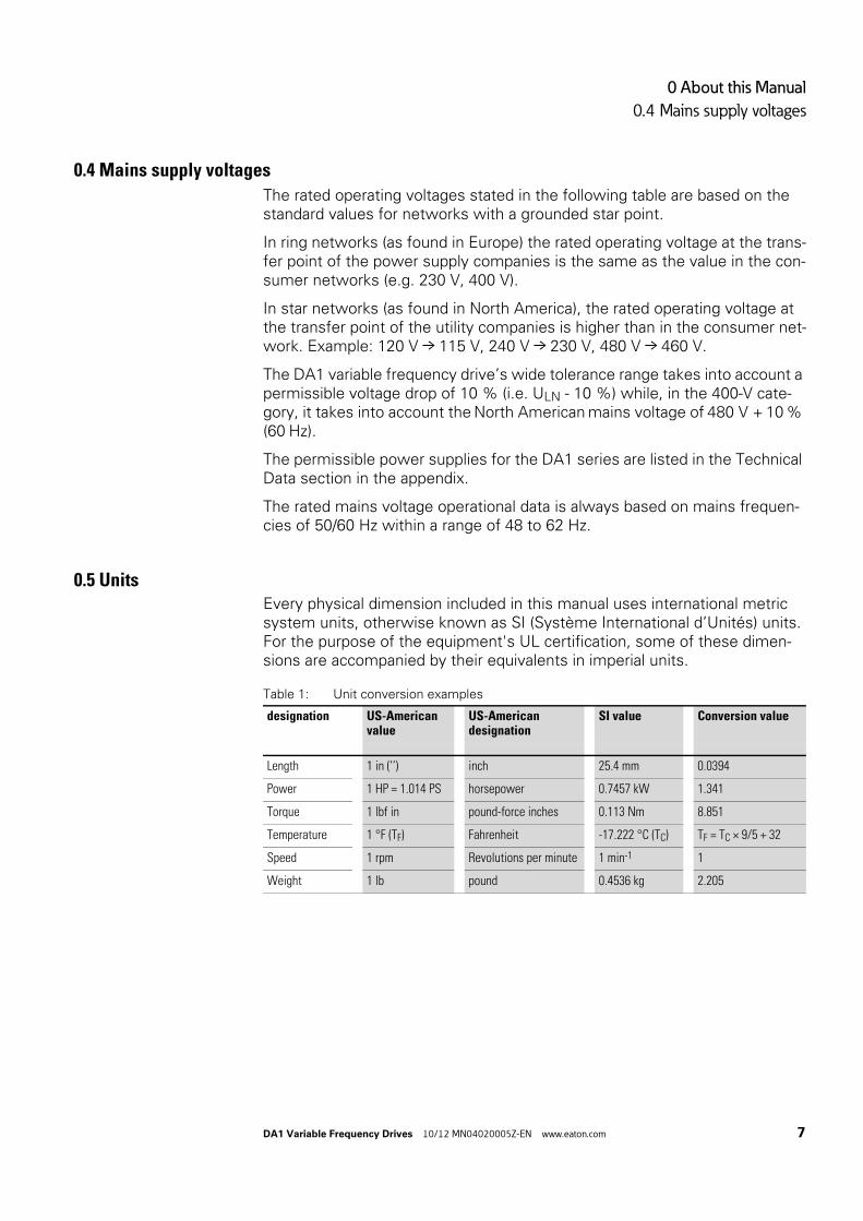
0.4 Mains supply voltages
The rated operating voltages stated in the following table are based on the standard values for networks with a grounded star point.
In ring networks (as found in Europe) the rated operating voltage at the trans-fer point of the power supply companies is the same as the value in the con-sumer networks (e.g. 230 V, 400 V).
In star networks (as found in North America), the rated operating voltage at the transfer point of the utility companies is higher than in the consumer net-work. Example: 120 V → 115 V, 240 V → 230 V, 480 V → 460 V.
The DA1 variable frequency drive’s wide tolerance range takes into account a permissible voltage drop of 10 % (i.e. ULN - 10 %) while, in the 400-V cate-gory, it takes into account the North American mains voltage of 480 V + 10 % (60 Hz).
The permissible power supplies for the DA1 series are listed in the Technical Data section in the appendix.
The rated mains voltage operational data is always based on mains frequen-cies of 50/60 Hz within a range of 48 to 62 Hz.
0.5 UnitsEvery physical dimension included in this manual uses international metric system units, otherwise known as SI (Système International d’Unités) units. For the purpose of the equipment's UL certification, some of these dimen-sions are accompanied by their equivalents in imperial units.
Table 1: Unit conversion examples
designation US-American value
US-Americandesignation
SI value Conversion value
Length 1 in (’’) inch 25.4 mm 0.0394
Power 1 HP = 1.014 PS horsepower 0.7457 kW 1.341
Torque 1 lbf in pound-force inches 0.113 Nm 8.851
Temperature 1 °F (TF) Fahrenheit -17.222 °C (TC) TF = TC × 9/5 + 32
Speed 1 rpm Revolutions per minute 1 min-1 1
Weight 1 lb pound 0.4536 kg 2.205

0 About this Manual
0.5 Units
8 DA1 Variable Frequency Drives 10/12 MN04020005Z-EN www.eaton.com

1 DA1 device series
1.1 Introduction
DA1 Variable Frequency Drives 10/12 MN04020005Z-EN www.eaton.com 9
1 DA1 device series
1.1 IntroductionDA1 series variable frequency drives are suited to applications involving the frequency control of motors within an output range of 0.75 kW (at 230 V) to 160 kW (at 400 V).
DA1 series devices feature a compact and rugged design and are available in seven sizes (FS2, ... , FS8), as well as with protection types IP20, IP40, IP55 and IP66. For protection type IP66, there is also a model with a mains switch and controls for local control available.
Due to their ease of use and handling, the innovative technology behind them, and a high level of reliability, DA1 variable frequency drives are particu-larly suitable for use in general applications. In addition, an integrated radio interference suppression filter and a flexible interface ensure that the invert-ers meet a number of important needs in the machine building industry when it comes to the optimization of production and manufacturing pro-cesses.
The computer-supported parameter configuration software ensures data integrity and reduces the time required for commissioning and maintenance.
In addition, the comprehensive accessories available increase the inverters’ flexibility in all areas of application.

1 DA1 device series
1.2 System overview
10 DA1 Variable Frequency Drives 10/12 MN04020005Z-EN www.eaton.com
1.2 System overview
Figure 1: DA1 variable frequency drives system overview
a DA1-… variable frequency drives
b DX-LN-… main chokes, DX-LM3-… motor reactors, DX-SIN3-… sinusoidal filters
c DX-BR… braking resistance
d Fieldbus connection and expansion group
e DX-COM-STICK communication module and accessories (e. g. DX-CBL-… connection cable)
f DE-KEY-… keypad (external)
⑤
②
③
⑥
OP
ST
PROFIBUS DP-V1
④
①
L1/L L2/N L3
DC-
U
DC+ BRV W
1 2 3 4 5 6 7 8 9 10 11 12 13
14 15 16 17 18
COM

1 DA1 device series
1.3 Checking the Delivery
DA1 Variable Frequency Drives 10/12 MN04020005Z-EN www.eaton.com 11
1.3 Checking the Delivery
Figure 2: Location of nameplate on DA1 variable frequency drive
The DA1 series variable frequency drives are carefully packaged and pre-pared for delivery. The devices should be shipped only in their original pack-aging with suitable transportation materials. Please take note of the labels and instructions on the packaging, as well as of those meant for the unpacked device.
Open the packaging with suitable tools and inspect the contents immediately after delivery to ensure that they are complete and undamaged.
→ Before opening the package, please check the label on it to make sure that you received the correct variable frequency drive.
L1/L L2/N L3
DC-
U
DC+ BRV W
1 2 3 4 5 6 7 8 9 10 11 12 13
14 15 16 17 18
COM

1 DA1 device series
1.3 Checking the Delivery
12 DA1 Variable Frequency Drives 10/12 MN04020005Z-EN www.eaton.com
The packaging must contain the following parts:
• DA1 series variable frequency drive,• an instructional leaflet
• IL04020010Z for devices with FS2 and FS3 size with IP20 protection type,
• IL04020011Z for devices with FS4 to FS7 sizes with IP55 protection type,
• IL04020012Z for panel-version variable frequency drives of size FS8• A data carrier (CD-ROM) containing documentation for DA1 series vari-
able frequency drives.
Figure 3: Equipment supplied with DA1 variable frequency drive
CD
L1/L L2/N L3
DC-
U
DC+ BR
1 2 3 4 5 6 7 8 9 10 11 12 13
14 15 16 17 18
COM
V W
IL

1 DA1 device series
1.4 Rated data
DA1 Variable Frequency Drives 10/12 MN04020005Z-EN www.eaton.com 13
1.4 Rated data
Voltage categories
DA1 variable frequency drives are divided into following voltage categories:
• 230 V: DA1-12…, DA1-32…• 400 V: DA1-34…
1.4.1 Rating data on the nameplateThe device-specific rated operational data for the DA1 variable frequency drive is listed on the nameplate on the right side of the device.
The inscription of the nameplate has the following meaning (example):
Inscription Meaning
DA1-344D1FB-A20N Part no.:DA1 = DA1 series variable frequency drive3 = Three-phase mains connection / three-phase motor connection4 = 400 V mains voltage category4D1 = 4.1 A rated operational current (4-decimal-1, output current)F = Integrated radio interference suppression filterB = Integrated brake chopperA = LED display (7-segment text display)20 = IP20 protection typeN = Standard basic device
Input Power connection rating:Three-phase AC voltage (Ue 3~ AC),380 - 480 V voltage, 50/60 Hz frequency, input phase current (4.3 A).
Output Load side (motor) rating:Three-phase AC voltage (0 - Ue), output phase current (4.1 A), output frequency(0 - 500 Hz)
Power Assigned motor output:1.5 kW at 400 V/2 HP at 460 V for a four-pole, internally cooled or surface-cooled three-phase motor (1500 rpm at 50 Hz/1800 rpm at 60 Hz)
S/N Serial number
Variable frequency drive is an electrical apparatus.Read the manual (in this case MN04020005Z-EN) before making any electrical connections and commissioning.
IP20/Open type Protection type of the housing: IP20, UL (cUL) Open type
25072012 Manufacturing date: 07-25-2012
a

1 DA1 device series
1.4 Rated data
14 DA1 Variable Frequency Drives 10/12 MN04020005Z-EN www.eaton.com
1.4.2 Key to part numbersThe catalog no. or part no. for the DA1 series of variable frequency drives is made up of four sections.
Series – Power section – Model – Version
The following figure shows it in greater detail:
Figure 4: Key to part numbers of the DA1 variable frequency drives
D A 1 - 1 2 4 D 1 F N - A 2 0 N Explanation
Type
N = Standard basic device
C = With coated printed circuit boards
Protection type
20 = IP20 / NEMA 0
40 = IP40 / NEMA 1
55 = IP55 / NEMA 3
66 = IP66 / NEMA 4X
6S = IP66 with switch / NEMA 4X, switched
Display unit (display)
A = LED display
B = OLED display
Brake Chopper
N = No internal brake chopper
B = Brake chopper
EMC (radio interference suppression filter)
N = No internal RFI filter
F = Internal RFI filter
Rated operational current (examples)
2D2 = 2.2 A
4D1 = 4.1 A
024 = 24 A
Mains voltage category
2 = 230 V (200 - 240 V ±10 %)
4 = 400 V (380 - 480 V ±10 %)
Connection in power section
1 = Single-phase mains connection / three-phase motor connection
3 = Three-phase mains connection / three-phase motor connection
Device series
DA1 = Variable frequency drive, advanced, Series 1
(D = Drives, A = Advanced, 1 = Series)

1 DA1 device series
1.4 Rated data
DA1 Variable Frequency Drives 10/12 MN04020005Z-EN www.eaton.com 15
Catalog number examples
Inscription Meaning
DA1-124D3NN-A20C DA1 = DA1 series variable frequency drive1 = Single-phase power supply2 = Mains voltage category: 230 V (200 V - 240 V ±10 %)4D3 = Rated operational current: 4.3 AN = No internal radio interference suppression filterN = No internal brake chopperA = LED display20 = IP20 protection typeC = Coated printed circuit boards
DA1-122D3FN-A20N DA1 = DA1 series variable frequency drive1 = Single-phase power supply2 = Mains voltage category: 230 V (200 V - 240 V ±10 %)2D3 = Rated operational current: 2.3 AN = Internal radio interference suppression filterN = No internal brake chopperA = LED display20 = IP20 protection typeN = Not coated printed circuit boards
DA1-327D0FB-A20N DA1 = DA1 series variable frequency drive3 = Three-phase mains supply voltage2 = Mains voltage category: 230 V (200 V - 240 V ±10 %)7D0 = Rated operational current: 7.0 AN = Internal radio interference suppression filterB = internal brake chopperA = LED display20 = IP20 protection typeN = Not coated printed circuit boards
DA1-34014FB-B66N DA1 = DA1 series variable frequency drive3 = Three-phase mains supply voltage4 = Mains voltage category: 400 V (380 V - 480 V ±10 %)014 = Rated operational current: 14 AN = Internal radio interference suppression filterB = internal brake chopperB = OLED display 66 = IP66 protection typeN = Not coated printed circuit boards
DA1-34018FB-A20C DA1= DA1 series variable frequency drive3 = Three-phase mains supply voltage4 = Mains voltage category: 400 V (380 V - 480 V ±10 %)018 = Rated operational current: 18 AN = Internal radio interference suppression filterB = internal brake chopperA = LED display20 = IP20 protection typeC = Coated printed circuit boards
→ For DA1-xxxxxNx-xxxx devices, an external radio interference suppression filter is required for operation as per IEC/EN 61800-3.
1 DA1 device series
1.4 Rated data
16 DA1 Variable Frequency Drives 10/12 MN04020005Z-EN www.eaton.com
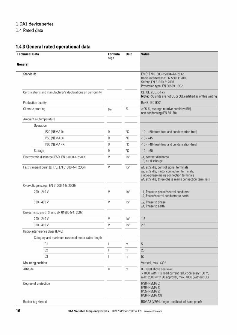
1.4.3 General rated operational data
Technical Data Formula sign
Unit Value
General
Standards EMC: EN 61800-3:2004+A1-2012Radio interference: EN 55011: 2010Safety: EN 61800-5: 2007Protection type: EN 60529: 1992
Certifications and manufacturer’s declarations on conformity CE, UL, cUL, c-TickNote: FS8 units are not UL or cUL certified as of this writing
Production quality RoHS, ISO 9001
Climatic proofing ρw % < 95 %, average relative humidity (RH),non-condensing (EN 50178)
Ambient air temperature
Operation
IP20 (NEMA 0) ϑ °C -10 - +50 (frost-free and condensation-free)
IP55 (NEMA 3) ϑ °C -10 - +45
IP66 (NEMA 4X) ϑ °C -10 - +40 (frost-free and condensation-free)
Storage ϑ °C -10 - +60
Electrostatic discharge (ESD, EN 61000-4-2:2009 V kV ±4, contact discharge±8, air discharge
Fast transient burst (EFT/B, EN 61000-4-4: 2004) V kV ±1, at 5 kHz, control signal terminals±2, at 5 kHz, motor connection terminals,single-phase mains connection terminals±4, at 5 kHz, three-phase mains connection terminals
Overvoltage (surge, EN 61000-4-5: 2006)
200 - 240 V V kV ±1, Phase to phase/neutral conductor±2, Phase/neutral conductor to earth
380 - 480 V V kV ±2, Phase to phase±4, Phase to earth
Dielectric strength (flash, EN 61800-5-1: 2007)
200 - 240 V V kV 1.5
380 - 480 V V kV 2.5
Radio interference class (EMC)
Category and maximum screened motor cable length
C1 l m 5
C2 l m 25
C3 l m 50
Mounting position Vertical, max. ±30°
Altitude H m 0 - 1000 above sea level,> 1000 with 1 % load current reduction every 100 m,max. 2000 with UL approval, max. 4000 (without UL)
Degree of protection IP20 (NEMA 0)IP40 (NEMA 1)IP55 (NEMA 3)IP66 (NEMA 4X)
Busbar tag shroud BGV A3 (VBG4, finger- and back-of-hand proof)
1 DA1 device series
1.4 Rated data
DA1 Variable Frequency Drives 10/12 MN04020005Z-EN www.eaton.com 17
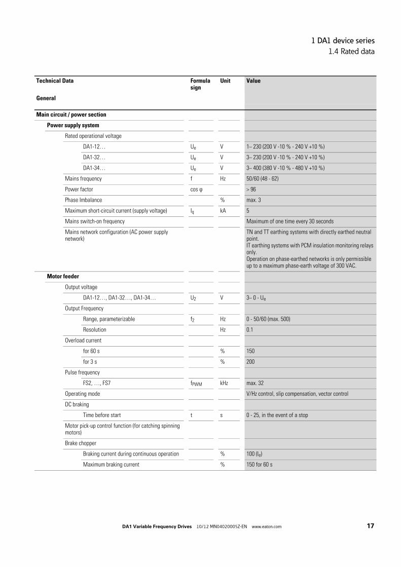
Main circuit / power section
Power supply system
Rated operational voltage
DA1-12… Ue V 1~ 230 (200 V -10 % - 240 V +10 %)
DA1-32… Ue V 3~ 230 (200 V -10 % - 240 V +10 %)
DA1-34… Ue V 3~ 400 (380 V -10 % - 480 V +10 %)
Mains frequency f Hz 50/60 (48 - 62)
Power factor cos ϕ > 96
Phase Imbalance % max. 3
Maximum short-circuit current (supply voltage) Iq kA 5
Mains switch-on frequency Maximum of one time every 30 seconds
Mains network configuration (AC power supply network)
TN and TT earthing systems with directly earthed neutral point. IT earthing systems with PCM insulation monitoring relays only. Operation on phase-earthed networks is only permissible up to a maximum phase-earth voltage of 300 VAC.
Motor feeder
Output voltage
DA1-12…, DA1-32…, DA1-34… U2 V 3~ 0 - Ue
Output Frequency
Range, parameterizable f2 Hz 0 - 50/60 (max. 500)
Resolution Hz 0.1
Overload current
for 60 s % 150
for 3 s % 200
Pulse frequency
FS2, …, FS7 fPWM kHz max. 32
Operating mode V/Hz control, slip compensation, vector control
DC braking
Time before start t s 0 - 25, in the event of a stop
Motor pick-up control function (for catching spinning motors)
Brake chopper
Braking current during continuous operation % 100 (Ie)
Maximum braking current % 150 for 60 s
Technical Data Formula sign
Unit Value
General

1 DA1 device series
1.4 Rated data
18 DA1 Variable Frequency Drives 10/12 MN04020005Z-EN www.eaton.com
Control section
Control Voltage
Output voltage (control signal terminal 1) UC V DC 24
Load rating (control terminal 1) I1 mA 100
Reference voltage (control terminal 5) US V DC 10
Load rating (control terminal 5) I5 mA 10
Digital input (DI)
Count 3 - 5
Logic (level) Increase
Response time t ms < 4
Input voltage range High (1) UC V DC 8 - 30
Input voltage range Low (0) UC V DC 0 - 4
Analog Input (AI)
Count 0 - 2
Resolution 12-bit
Accuracy % < 1 to the final value
Response time t ms < 4
Input voltage range US V DC -10 - +10, (Ri ~ 72 kΩ)
Input current range IS mA 0/4 - 20 (RB ~ 500 Ω)
Digital output (DO) / relay output (K)
Count 2 (analog/digital) / 2 relay
Output voltage Uout V DC 0 - 10, 24
Output current Iout mA 0/4 - 20
Relays N/O contact, 6 A (250 V AC) / 5 A (30 V DC)Changeover contacts, 6 A (250 V AC) / 5 A (30 V DC)
Interface (RJ45) OP bus, Modbus RTU, CANopen
Control level Control signal terminal/operating unit/interface
Technical Data Formula sign
Unit Value
General

1 DA1 device series
1.4 Rated data
DA1 Variable Frequency Drives 10/12 MN04020005Z-EN www.eaton.com 19
1.4.4 Features
Part no.R
ate
d o
pe
ra-
tion
al c
urre
nt Assigned motor power
Rad
io i
nter
-fe
renc
e su
ppre
ssio
n
Bra
ke
chop
per
(in
teg
rate
d)
Pro
tect
ion
type
Siz
e
Ie P(230 V, 50 Hz)
P(220 - 240 V, 60 Hz)
N = NoF = Yes
N = NoB = Yes
IP FS
[A] [kW] [A]1) [HP] [A]1)
Mains supply voltage: 1 AC 230 VMotor connection voltage: 3 AC 230 V, 50/60 Hz
DA1-124D3… 4.3 0.75 3.2 1 4.2 F N IP20, IP66 FS2
DA1-127D0… 7 1.5 6.3 2 6.8 F N IP20, IP66 FS2
DA1-12011… 11 2.2 8.7 3 9.6 F N, B IP20, IP66 FS2
Mains supply voltage: 3 AC 230 V, 50/60 HzMotor connection voltage: 3 AC 230 V, 50/60 Hz
DA1-324D3… 4.3 0.75 3.2 1 4.2 F B IP20, IP66 FS2
DA1-327D0… 7 1.5 6.3 2 6.8 F B IP20, IP66 FS2
DA1-32011… 10.5 2.2 8.7 3 9.6 F B IP20, IP66 FS2
DA1-32012… 18 4 14.8 5 15.2 F B IP20, IP66 FS3
DA1-32024… 24 5.5 19.6 7.5 22 F B IP20, IP66 FS3
DA1-32024… 24 5.5 19.6 7.5 22 F B IP55 FS4
DA1-32039… 39 7.5 26.4 10 28 F B IP55 FS4
DA1-32046… 46 11 38 15 42 F B IP55 FS4
DA1-32061… 61 15 51 20 54 F B IP55 FS5
DA1-32072… 72 18.5 63 25 68 F B IP55 FS5
DA1-32090… 90 22 71 30 80 F B IP55 FS6
DA1-32110… 110 30 96 40 104 F B IP55 FS6
DA1-32150… 150 37 117 50 130 F B IP55 FS6
DA1-32180… 180 45 141 60 154 F B IP55 FS6
DA1-32202… 202 55 173 75 192 F B IP55 FS7
DA1-32248… 248 75 233 100 248 F B IP55 FS7
1) The rated motor currents apply to normal internally and surface-cooled three-phase asynchronous motor (1500 rpm at 50 Hz, 1800 rpm at 60 Hz).
2) Take motor data into account (6 A = normalized rated value as per UL 580 C)Operation may be limited to a reduced motor load.

1 DA1 device series
1.4 Rated data
20 DA1 Variable Frequency Drives 10/12 MN04020005Z-EN www.eaton.com
Part no.
Rat
ed o
pera
-ti
onal
cur
rent Assigned motor power
Ra
dio
inte
r-fe
ren
ce
su
pp
ress
ion
Bra
ke
ch
oppe
r(i
nteg
rate
d)
Deg
ree
of
prot
ecti
on
Siz
e
Ie P(400 V, 50 Hz)
P(440 - 480 V, 60 Hz)
N = NoF = Yes
N = NoB = Yes
IP FS
[A] [kW] [A]1) [HP] [A]1)
Mains supply voltage: 3 AC 400 V, 50 Hz / 480 V, 60 HzMotor connection voltage: 3 AC 400 V, 50 Hz / 440 - 480 V, 60 Hz
DA1-342D2… 2.2 0.75 1.9 1 2.1 F B IP20, IP66 FS2
DA1-344D1… 4.1 1.5 3.6 2 3.4 F B IP20, IP66 FS2
DA1-345D8… 5.8 2.2 5 3 4.8 F B IP20, IP66 FS2
DA1-349D5… 9.5 4 8.5 5 7.6 F B IP20, IP66 FS2
DA1-34014… 14 5.5 11.3 7.5 11 F B IP20, IP66 FS3
DA1-34018… 18 7.5 15.2 10 14 F B IP20, IP66 FS3
DA1-34024… 24 11 21.7 15 21 F B IP20, IP66 FS3
DA1-34024… 24 11 21.7 15 21 F B IP55 FS4
DA1-34030… 30 15 29.3 20 27 F B IP55 FS4
DA1-34039… 39 18.5 36 25 34 F B IP55 FS4
DA1-34046… 46 22 41 30 40 F B IP55 FS4
DA1-34061… 61 30 55 40 52 F B IP55 FS5
DA1-34072… 72 37 68 50 65 F B IP55 FS5
DA1-34090… 90 45 81 60 77 F B IP55 FS6
DA1-34110… 110 55 99 75 96 F B IP55 FS6
DA1-34150… 150 75 134 100 124 F B IP55 FS6
DA1-34180… 180 90 161 125 156 F N, B IP55 FS6
DA1-34202… 202 110 196 150 180 F N, B IP55 FS7
DA1-34240… 240 132 231 200 240 F N, B IP55 FS7
DA1-34302… 302 160 279 250 302 F N, B IP55 FS7
DA1-34370… 370 200 349 300 361 F N, B IP40 FS8
DA1-34450… 450 250 437 350 414 F N, B IP40 FS8
1) The rated motor currents apply to normal internally and surface-cooled three-phase asynchronous motor (1500 rpm at 50 Hz, 1800 rpm at 60 Hz).

1 DA1 device series
1.5 DA1 layout
DA1 Variable Frequency Drives 10/12 MN04020005Z-EN www.eaton.com 21
1.5 DA1 layout
The following drawing shows examples of named elements of the DA1 variable frequency drives in different frame sizes.
Figure 5: Designation on the DA1 variable frequency drive
a Fixing holes (screw fastening)
b Connection terminals in power section (mains side)
c Cutout for mounting on mounting rail (only for FS2 and FS3)
d Control terminals (plug-in)
e Relay terminals (plug-in)
f Connection terminals in power section (motor feeder)
g Slot for field bus card or expansion module
h Communication interface (RJ45)
i Operating unit with 5 control signal terminals and LED display
j Info card
⑩
⑨
⑦
①
②
③
⑥
④⑤
⑧
L1/L L2/N L3
DC-
U
DC+ BR
1 2 3 4 5 6 7 8 9 10 11 12 13
14 15 16 17 18
COM
V W

1 DA1 device series
1.6 Features
22 DA1 Variable Frequency Drives 10/12 MN04020005Z-EN www.eaton.com
1.6 Features
DA1 series variable frequency drives convert the voltage and frequency of an existing AC supply system into a DC voltage. This DC voltage is used to generate a three-phase AC voltage with adjustable frequency and assigned amplitude values for the variable speed control of three-phase asynchronous motors.
Figure 6: Block diagram; components in a DA1 variable frequency drive
a L1/L, L2/N, L3, PE supply, mains supply voltage ULN = Ue at 50/60 Hz:DA1-12…: single-phase mains connection (1 AC/2 AC 230 V/240 V), motor feeder (3 AC 230 V)DA1-32…: single-phase mains connection (3 AC 230 V/240 V), motor feeder (3 AC 230 V)DA1-34…: single-phase mains connection (3 AC 400 V/480 V), motor feeder (3 AC 400 V)
b Internal radio interference suppression filter, EMC connection to PE
c Internal voltage filter, VAR connection to PE
d Rectifier bridge: it converts the AC voltage of the electrical supply to a DC voltage.
e Internal DC link with charging resistor, capacitor and switched-mode power supply unit (SMPS = Switching-Mode Power Supply).
f Brake chopper for external braking resistor (DC+ and BR connection)
g Inverter. The IGBT based inverter converts the DC voltage of the DC link (UDC) into a three-phase AC voltage (U2) with variable amplitude and frequency (f2).
h Motor connection with output voltage U2 (0 to 100 % Ue) and output frequency f2 (0 to 500 Hz)The connection in the motor feeder is implemented with a screened cable that is earthed on both sides across a large area (PES). Rated operational current (Ie, output current):DA1-12…: 4.3 - 10.5 ADA1-32…: 4.3 - 248 ADA1-34…: 2.2 - 450 A100 % at an ambient temperature of +50 °C with an overload capability of 150 % for 60 sand a starting current of 175 % for 2 s.
i Three-phase asynchronous motor, variable speed control of three-phase asynchronous motor for assigned motor shaft power values (P2):DA1-12…: 0.75 - 2.2 kW (230 V, 50 Hz) oder 1 - 3 HP (230 V, 60 Hz)DA1-32…: 0.75 - 75 kW (230 V, 50 Hz) oder 1 - 100 HP (230 V, 60 Hz)DA1-34…: 0.75 - 160 kW (400 V, 50 Hz) oder 1 - 255 HP (460 V, 60 Hz)
+
-
+
-
+
-
M3 ~U
L3
L2/N
L1/L
W
V
U
②① ③ ④ ⑤ ⑥ ⑦
⑩
⑧ ⑨DC+DC- BR
EMC VAR
CPU STO
1 … 11, 14 … 18 12 13
PES⑫
⑪

1 DA1 device series
1.6 Features
DA1 Variable Frequency Drives 10/12 MN04020005Z-EN www.eaton.com 23
j Control section with operating unit and control buttons, 7-digital display assembly, control voltage, plug-in control signal terminals, plug-in relay terminal
k RJ45 interface for the PC and fieldbus connection (Modbus RTU, CANopen)
l Safe Torque-OffSafe removal of torque as per SIL 2 (EN 61508) / PL d (EN ISO 13849-1)
1 DA1 device series
1.7 Selection criteria
24 DA1 Variable Frequency Drives 10/12 MN04020005Z-EN www.eaton.com
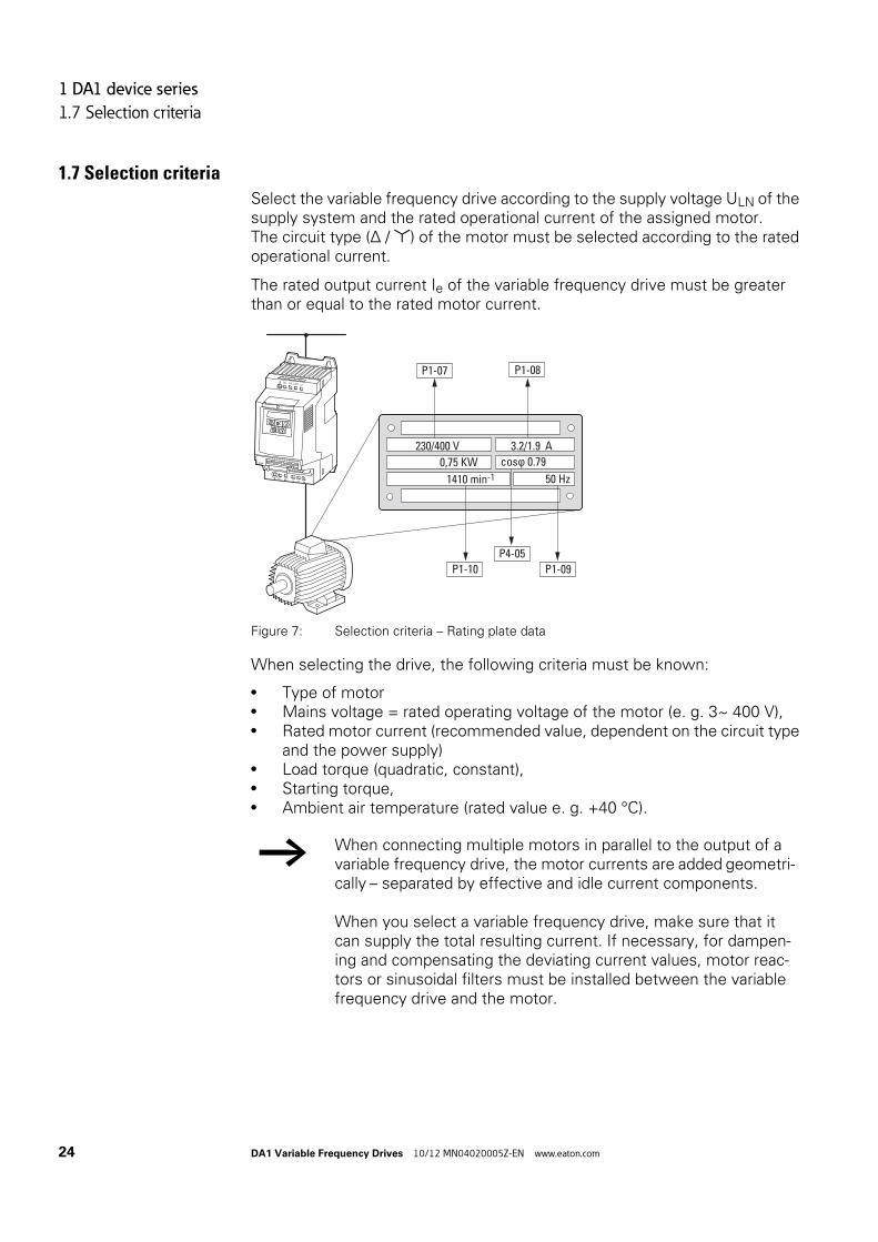
1.7 Selection criteria
Select the variable frequency drive according to the supply voltage ULN of the supply system and the rated operational current of the assigned motor.The circuit type (Δ / ) of the motor must be selected according to the rated operational current.
The rated output current Ie of the variable frequency drive must be greater than or equal to the rated motor current.
Figure 7: Selection criteria – Rating plate data
When selecting the drive, the following criteria must be known:
• Type of motor• Mains voltage = rated operating voltage of the motor (e. g. 3~ 400 V),• Rated motor current (recommended value, dependent on the circuit type
and the power supply)• Load torque (quadratic, constant),• Starting torque,• Ambient air temperature (rated value e. g. +40 °C).
→ When connecting multiple motors in parallel to the output of a variable frequency drive, the motor currents are added geometri-cally – separated by effective and idle current components.
When you select a variable frequency drive, make sure that it can supply the total resulting current. If necessary, for dampen-ing and compensating the deviating current values, motor reac-tors or sinusoidal filters must be installed between the variable frequency drive and the motor.
L1/L L2/N L3
DC-
U
DC+ BR
1 2 3 4 5 6 7 8 9 10 11 12 13
14 15 16 17 18
COM
V W
P1-07 P1-08
P1-10 P1-09
P4-05
1410 min-1
230/400 V 3.2/1.9 A
50 Hz
0,75 KW cos ϕ 0.79
1 DA1 device series
1.8 Proper use
DA1 Variable Frequency Drives 10/12 MN04020005Z-EN www.eaton.com 25
1.8 Proper use
The DA1 variable frequency drives are not domestic appliances. They are designed only for industrial use as system components.
The DA1 variable frequency drives are electrical devices for controlling vari-able speed drives with three-phase motors. They are designed for installation in machines or for use in combination with other components within a machine or system.
After installation in a machine, the variable frequency drives must not be taken into operation until the associated machine has been confirmed to comply with the safety requirements of Machinery Safety Directive (MSD) 89/392/EEC (meets the requirements of EN 60204). The user of the equip-ment is responsible for ensuring that the machine use complies with the relevant EU Directives.
The CE markings on the DA1 variable frequency drive confirm that, when used in a typical drive configuration, the apparatus complies with the Euro-pean Low Voltage Directive (LVD) and the EMC Directives (Directive 73/23/EEC, as amended by 93/68/EEC and Directive 89/336/EEC, as amended by 93/68/EEC).
In the described system configurations, DA1 variable frequency drives are suitable for use in public and non-public networks.
A connection of a DA1 variable frequency drive to IT networks (networks without reference to earth potential) is permissible only to a limited extent, since the device’s built-in filter capacitors connect the network with the earth potential (enclosure).
On earth free networks, this can lead to dangerous situations or damage to the device (isolation monitoring required).
Observe the technical data and connection requirements. For additional information, refer to the equipment nameplate or label of the variable frequency drive and the documentation. Any other usage constitutes improper use.
→ To the output (terminals U, V, W) of the DA1 variable frequency drive you must not:
• connect a voltage or capacitive loads (e.g. phase compensa-tion capacitors),
• connect multiple variable frequency drives in parallel,• make a direct connection to the input (bypass).

1 DA1 device series
1.9 Maintenance and inspection
26 DA1 Variable Frequency Drives 10/12 MN04020005Z-EN www.eaton.com
1.9 Maintenance and inspection
DA1 series variable frequency drives will be maintenance-free as long as the general rated operational data (→ Section 1.4.3, “General rated operational data“, page16) is adhered to and the specific technical data (see appendix) for the corresponding ratings is taken into account. Please note, however, that external influences may affect the operation and lifespan of a DA1 vari-able frequency drive.
We therefore recommend that the devices are checked regularly and the fol-lowing maintenance measures are carried out at the specified intervals.
Table 2: Recommended maintenance for DA1 variable frequency drives
There are no plans for replacing or repairing individual components of DA1 variable frequency drives.
If the DA1 variable frequency drive is damaged by external influences, repair is not possible.
Dispose of the device according to the applicable environmental laws and provisions for the disposal of electrical or electronic devices.
1.10 StorageIf the DA1 variable frequency drive is stored before use, suitable ambient conditions must be ensured at the site of storage:
• Storage temperature: -40 - +70 °C,• Relative average air humidity: < 95 %, non condensing (EN 50178),• To prevent damage to the RASP DC link capacitors, storage times longer
than 12 months are not recommended (→ Section 1.11, “Charging the internal DC link capacitors“).
Maintenance measures Maintenance interval
Clean cooling vents (cooling slits) Please enquire
Check the fan function 6 - 24 months (depending on the environment)
Filter in the switching cabinet doors (see manufacturer specifications)
6 - 24 months (depending on the environment)
Check all earth connections to make sure they are intact
On a regular basis, at periodic intervals
Check the tightening torques of the terminals (control signal terminals, power terminals)
On a regular basis, at periodic intervals
Check connection terminals and all metallic surfaces for corrosion
6 - 24 months; when stored, no more than 12 months later (depending on the environment)
Motor cables and shield connection (EMC) According to manufacturer specifications, no later than 5 years
Charge capacitors 12 months(→ Section 1.11, “Charging the internal DC link capacitors“)

1 DA1 device series
1.11 Charging the internal DC link capacitors
DA1 Variable Frequency Drives 10/12 MN04020005Z-EN www.eaton.com 27
1.11 Charging the internal DC link capacitors
After extended storage times or extended downtimes during which no power is supplied (> 12 months), the capacitors in the internal DC link must be recharged in a controlled manner in order to prevent damage. To do this, the DA1 variable frequency drive must be supplied with power, with a con-trolled DC power supply unit, via two mains connection terminals (e.g. L1 and L2).
In order to prevent the capacitors from having excessively high leakage cur-rents, the inrush current should be limited to approximately 300 to 800 mA (depending on the relevant rating). The variable frequency drive must not be enabled during this time (i.e. no start signal). After this, the DC voltage must be set to the magnitudes for the corresponding DC link voltage (UDC ∼ 1.41 x Ue) and applied for one hour at least (regeneration time).
• DA1-12…, DA1-32…: about 324 V DC at Ue = 230 V AC.• DA1-34…: about 560 V DC at Ue = 400 V AC.
1.12 Service and warrantyIn the unlikely event that you have a problem with your DA1 variable fre-quency drive, please contact your local sales office.
When you call, have the following data ready:
• The exact variable frequency drive part number (see nameplate),• the date of purchase,• a detailed description of the problem which has occurred with the
variable frequency drive.
If some of the information printed on the rating plate is not legible, please state only the data which are clearly legible.
Information concerning the guarantee can be found in the Terms and Conditions Eaton Industries GmbH.
24-hour hotline: +49 (0)1805 223 822
E-Mail: [email protected]

1 DA1 device series
1.12 Service and warranty
28 DA1 Variable Frequency Drives 10/12 MN04020005Z-EN www.eaton.com

2 Engineering
2.1 Introduction
DA1 Variable Frequency Drives 10/12 MN04020005Z-EN www.eaton.com 29
2 Engineering
2.1 IntroductionThis chapter describes the most important features in the energy circuit of a magnet system (PDS = Power Drive System), which you should take into consideration in your project planning.
Figure 8: Example of a magnet system with a three-phase feeder unitfor a three-phase motor
a Network configuration, mains voltage, mains frequency, interaction with p.f. correction systems
b Fuses and cable cross-sections, cable protection
c Protection of persons and domestic animals with residual current protective devices
d Mains contactor
e Main choke, radio interference filter, line filter
f Variable frequency drive: mounting; installation; power connection; EMC compliance;circuit examples
g Motor reactor, dV/dt filter, sinusoidal filter
h Motor protection; Thermistor overload relay for machine protection
i Cable lengths, motor cables, shielding (EMC)
j Motor and application, parallel operation of multiple motors on a variable frequency drive(only for V/f), bypass circuit; DC braking
k Braking resistance; dynamic braking
③
②
①
L1L2L3PE
⑤
④
⑦
⑩
⑨
⑧
⑥
RCD
L1/L L2/N
PE U V W
L3 PE
DC+ BR
M3 ϑ˜
PES
PES
#
I > I > I >
⑪

2 Engineering
2.2 Electrical power network
30 DA1 Variable Frequency Drives 10/12 MN04020005Z-EN www.eaton.com
2.2 Electrical power network
2.2.1 Mains connection and configurationThe variable frequency drives of the DA1 series can be connected and oper-ated with all control-point grounded AC supply systems (see IEC 60364 for more information in this regard).
Figure 9: AC power networks with earthed center point (TN-/TT networks)
The connection and operation of variable frequency drives to asymmetrically grounded TN networks (phase-grounded Delta network “Grounded Delta“, USA) or non-grounded or high-resistance grounded (over 30 Ω) IT networks is only conditionally permissible.
If DA1 series variable frequency drives are connected to an asymmetrically earthed network or to an IT network (non-earthed, insulated), the internal radio interference suppression filter must be disconnected (by unscrewing the screw marked EMC).
Figure 10: EMC screw location
→ While planning the project, consider a symmetrical distribution to the three main poles, if multiple variable frequency drives with single-phase incoming unit are to be connected.The total current of all single phase consumers is not to cause an over-load of the neutral conductor (N-conductor).
→ Operation on non-earthed networks (IT) requires the use of suit-able insulation monitors (e.g. pulse-code measurement method).
→ In networks with an earthed main pole, the maximum phase-earth voltage must not exceed 300 VAC.
L2
N
L1
L3
PE
L2
PEN
L1
L3
EMC
L3UL2/N
L1/L
VAR
PH1
M3
20 mm (0.79")
EMC
VAR
2 Engineering
2.2 Electrical power network
DA1 Variable Frequency Drives 10/12 MN04020005Z-EN www.eaton.com 31
The required filter winding for electromagnetic compatibility (EMC) no longer exists in this case.
2.2.2 Mains voltage and frequencyThe standardized rated operating voltages (IEC 60038, VDE 017-1) of power utilities guarantee the following conditions at the connection point:
• Deviation from the rated value of voltage:maximum ±10 %
• Deviation in voltage phase balance:maximum ±3 %
• Deviation from rated value of the frequency:maximum ±4 %
The broad tolerance band of the DA1 variable frequency drive considers the rated value for European as (EU: ULN = 230 V/400 V, 50 Hz) and American as (USA: ULN = 240 V/480 V, 60 Hz) standard voltages:
• 230 V, 50 Hz (EU) and 240 V, 60 Hz (USA) at DA1-12…, DA1-32…200 V - 10 % - 240 V + 10 % (190 V - 0 % - 264 V + 0 %)
• 400 V, 50 Hz (EU) and 480 V, 60 Hz (USA) at DA1-34…380 V - 10 % - 480 V + 10 % (370 V - 0 % - 528 V + 0 %)
The permissible frequency range for all voltage categories is 50/60 Hz (48 Hz - 0 % - 62 Hz + 0 %).
2.2.3 Voltage balanceBecause of the uneven loading on the conductor and with the direct connec-tion of greater power ratings, deviations from the ideal voltage form and asymmetrical voltages can be caused in three-phase AC power networks. These asymmetric divergences in the mains voltage can lead to different loading of the diodes in mains rectifiers with three-phase supplied variable frequency drives and as a result, to an advance failure of this diode.
If this condition is not fulfilled, or symmetry at the connection location is not known, the use of an assigned main choke is recommended.
→ Measures for electromagnetic compatibility are mandatory in a magnet system, to meet the legal standards for EMC- and low-voltage regulations.
Good earthing measures are a prerequisite for the effective insert of further measures such as screen earth kit or filters here. Without respective grounding measures, further steps are superfluous.
→ In the project planning for the connection of three-phase sup-plied variable frequency drives (DA1-3…), consider only AC supply systems that handle permitted asymmetric divergences in the mains voltage ≦ +3 %.
2 Engineering
2.2 Electrical power network
32 DA1 Variable Frequency Drives 10/12 MN04020005Z-EN www.eaton.com
2.2.4 Total Harmonic Distortion (THD)Non-linear consumers (loads) in an AC supply system produce harmonic volt-ages that again result in harmonic currents. These harmonic currents at the inductive and capacitive reactances of a mains supply system produce addi-tional voltage drops with different values which are then overlaid on the sinu-soidal mains voltage and result in distortions. In supply systems, this form of "noise" can give rise to problems in an installation if the sum of the harmonics exceeds certain limit values.
Non-linear consumers (harmonics producers) include for example:
• Induction and arc furnaces, welding devices,• Current converters, rectifiers and inverters, soft starters, variable fre-
quency drives,• Switched-mode power supply units (computers, monitors, lighting),
uninterrupted power supply (UPS).
The THD value (THD = Total Harmonic Distortion) is defined in standardIEC/EN 61800-3 as the ratio of the rms value of all harmonic components to the rms value of the fundamental frequency. For example, the THD for a current is:
Where I1 is the rms value of the fundamental frequency current and n is the order of a harmonic with its own frequency, which is an integer multiple of the fundamental frequency (Fourier analysis). Example: 5th harmonic of a mains frequency of 50 Hz : 5 x 50 Hz = 250 Hz.
The THD value of the harmonic distortion is stated in relation to the rms value of the total signal as a percentage. On a variable frequency drive, the total harmonic distortion is around 120 %. A mains choke (such as 4 % uk) on the supply side of a variable frequency drive enables the THD value with a single-phase supply (B2 diode rectifier bridge) to be reduced to around 80 % and with a three-phase supply (B6 diode rectifier bridge) to around 50 %.The supply quality is thus improved and the mains supply distortion is reduced. The power factor is also improved.
THDn 2xx=
I1
-----------------------=
∞n=2Σ In
2
2 Engineering
2.2 Electrical power network
DA1 Variable Frequency Drives 10/12 MN04020005Z-EN www.eaton.com 33
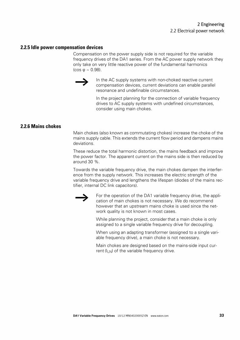
2.2.5 Idle power compensation devicesCompensation on the power supply side is not required for the variable frequency drives of the DA1 series. From the AC power supply network they only take on very little reactive power of the fundamental harmonics (cos ϕ ~ 0.98).
2.2.6 Mains chokesMain chokes (also known as commutating chokes) increase the choke of the mains supply cable. This extends the current flow period and dampens mains deviations.
These reduce the total harmonic distortion, the mains feedback and improve the power factor. The apparent current on the mains side is then reduced by around 30 %.
Towards the variable frequency drive, the main chokes dampen the interfer-ence from the supply network. This increases the electric strength of the variable frequency drive and lengthens the lifespan (diodes of the mains rec-tifier, internal DC link capacitors).
→ In the AC supply systems with non-choked reactive current compensation devices, current deviations can enable parallel resonance and undefinable circumstances.
In the project planning for the connection of variable frequency drives to AC supply systems with undefined circumstances, consider using main chokes.
→ For the operation of the DA1 variable frequency drive, the appli-cation of main chokes is not necessary. We do recommend however that an upstream mains choke is used since the net-work quality is not known in most cases.
While planning the project, consider that a main choke is only assigned to a single variable frequency drive for decoupling.
When using an adapting transformer (assigned to a single vari-able frequency drive), a main choke is not necessary.
Main chokes are designed based on the mains-side input cur-rent (ILN) of the variable frequency drive.

2 Engineering
2.3 Safety and switching
34 DA1 Variable Frequency Drives 10/12 MN04020005Z-EN www.eaton.com
2.3 Safety and switching
2.3.1 Fuses and cable cross-sectionsThe fuses and wire cross-sections allocated for power-side connections depend on the rated mains current ILN of the variable frequency drive (with-out main choke).
The recommended fuses and their assignment to the variable frequency drives are listed in Page 218 the appendix.
The national and regional standards (for example VDE 0113, EN 60204) must be observed and the necessary approvals (for example UL) at the site of installation must be fulfilled.
When the device is operated in a UL-approved system, use only UL-approved fuses, fuse bases and cables. The permissible cables must have a heat resis-tance of 75 °C.
The connection terminals marked with and the metallic enclosure (IP66) must be connected to the earth-current circuit.
The leakage currents to earth (as per EN 50178) are greater than 3.5 mA.They are listed for the individual ratings in the appendix, under the specific technical data on Page 203.
A completely (360°) screened low impedance cable on the motor side is required. The length of the motor cable depends on the RFI class and the environment.
NOTICE
When selecting the cable cross-section, take the voltage drop under load conditions into account.
The consideration of other standards (e.g. VDE 0113 or VDE 0289) is the responsibility of the user.
→ As per the requirements in standard EN 50178, a protective earth (PE) must be connected. The cable cross-section must be at least 10 mm2 or consist of two separately connected earthing cables.
NOTICE
The specified minimum PE conductor cross-sections (EN 50178, VDE 0160) must be maintained.
→ Choose the cross-section of the PE conductor in the motor lines at least as large as the cross-section of the phase lines (U, V, W).
2 Engineering
2.3 Safety and switching
DA1 Variable Frequency Drives 10/12 MN04020005Z-EN www.eaton.com 35
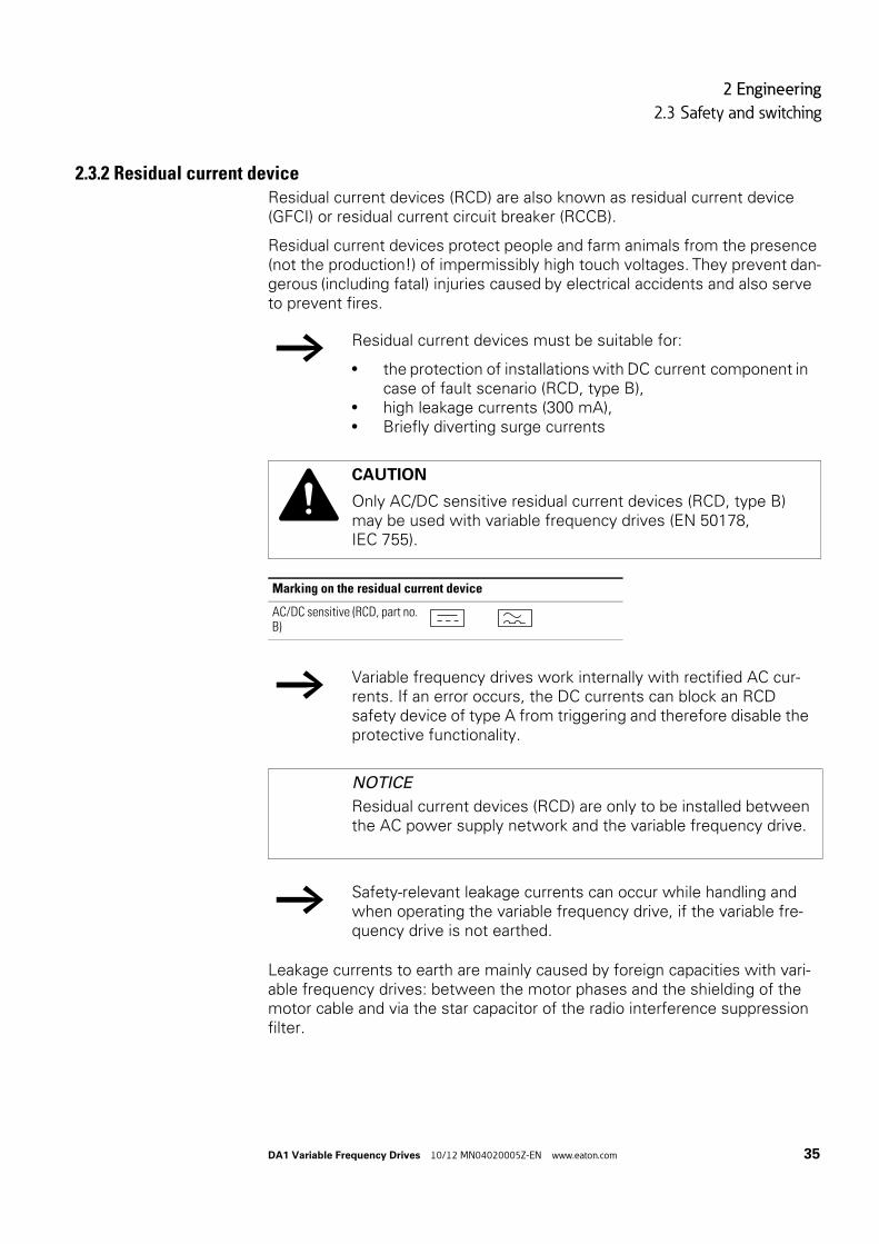
2.3.2 Residual current deviceResidual current devices (RCD) are also known as residual current device (GFCI) or residual current circuit breaker (RCCB).
Residual current devices protect people and farm animals from the presence (not the production!) of impermissibly high touch voltages. They prevent dan-gerous (including fatal) injuries caused by electrical accidents and also serve to prevent fires.
Leakage currents to earth are mainly caused by foreign capacities with vari-able frequency drives: between the motor phases and the shielding of the motor cable and via the star capacitor of the radio interference suppression filter.
→ Residual current devices must be suitable for:
• the protection of installations with DC current component in case of fault scenario (RCD, type B),
• high leakage currents (300 mA),• Briefly diverting surge currents
CAUTION
Only AC/DC sensitive residual current devices (RCD, type B) may be used with variable frequency drives (EN 50178, IEC 755).
Marking on the residual current device
AC/DC sensitive (RCD, part no. B)
→ Variable frequency drives work internally with rectified AC cur-rents. If an error occurs, the DC currents can block an RCD safety device of type A from triggering and therefore disable the protective functionality.
NOTICE
Residual current devices (RCD) are only to be installed between the AC power supply network and the variable frequency drive.
→ Safety-relevant leakage currents can occur while handling and when operating the variable frequency drive, if the variable fre-quency drive is not earthed.

2 Engineering
2.4 EMC compliance
36 DA1 Variable Frequency Drives 10/12 MN04020005Z-EN www.eaton.com
The size of the leakage currents is mainly dependent upon the:
• length of the motor cable,• shielding of the motor cable,• height of the pulse frequency (switching frequency of the inverter),• Design of the radio interference suppression filter• grounding measures at the site of the motor.
2.3.3 Mains contactorsThe mains contactor enables an operational switching on and off of the sup-ply voltage for the variable frequency drive and switching off in case of a fault.
The mains contactor is designed based on the mains-side input current ILN of the variable frequency drive for utilization category AC-1 (IEC 60947) and the ambient air temperature at the location of use. Mains contactors and their assignment to the variable frequency drives belonging to the DC1 series are listed in the appendix (Table 27, page 220).
2.4 EMC complianceElectrical components in a system (machine) have a reciprocal effect on each other. Each device not only emits interference but is also affected by it. This occurs as a result of galvanic, capacitive and/or inductive coupling or through electromagnetic radiation. In practice, the limit between line-conducted inter-ference and emitted interference is around 30 MHz. At values above 30 MHz the lines and cables act like antennas and radiate the electromagnetic waves.
Electromagnetic compatibility (EMC) for frequency controlled drives (variable speed drives) is implemented in accordance with product standard IEC/EN 61800-3. This includes the complete power magnet system (PDS = Power Drive System), from the mains supply to the motor, including all compo-nents, as well as cables (→ Figure 8, page 29). This type of drive system can also consist of several individual drives.
The generic standards of the individual components in a magnet system compliant with IEC/EN 61800-3 do not apply. These component manufactur-ers, however, must offer solutions that ensure standards-compliant use.
In Europe, maintaining the EMC Directive is mandatory.
→ While planning the project, make sure that inching operation is not done via the mains contactor of the variable frequency drive on frequency-controlled drives, but through a controller input of the variable frequency drive.
The maximum permissible mains voltage switch-on frequency for the DA1 variable frequency drive is once every 30 seconds (normal operation).
2 Engineering
2.4 EMC compliance
DA1 Variable Frequency Drives 10/12 MN04020005Z-EN www.eaton.com 37
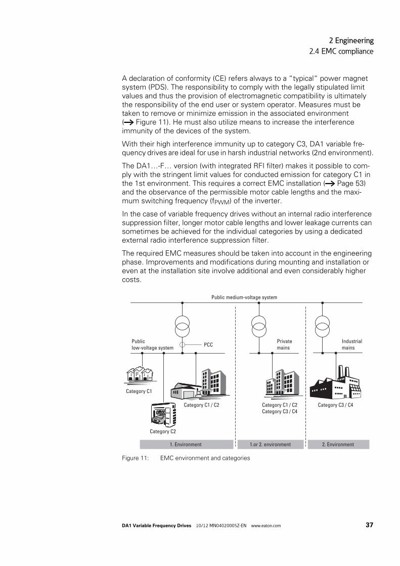
A declaration of conformity (CE) refers always to a “typical“ power magnet system (PDS). The responsibility to comply with the legally stipulated limit values and thus the provision of electromagnetic compatibility is ultimately the responsibility of the end user or system operator. Measures must be taken to remove or minimize emission in the associated environment (→ Figure 11). He must also utilize means to increase the interference immunity of the devices of the system.
With their high interference immunity up to category C3, DA1 variable fre-quency drives are ideal for use in harsh industrial networks (2nd environment).
The DA1…-F… version (with integrated RFI filter) makes it possible to com-ply with the stringent limit values for conducted emission for category C1 in the 1st environment. This requires a correct EMC installation (→ Page 53) and the observance of the permissible motor cable lengths and the maxi-mum switching frequency (fPWM) of the inverter.
In the case of variable frequency drives without an internal radio interference suppression filter, longer motor cable lengths and lower leakage currents can sometimes be achieved for the individual categories by using a dedicated external radio interference suppression filter.
The required EMC measures should be taken into account in the engineering phase. Improvements and modifications during mounting and installation or even at the installation site involve additional and even considerably higher costs.
Figure 11: EMC environment and categories
1. Environment
Public medium-voltage system
PCC
Category C1
Category C2
Category C1 / C2 Category C1 / C2Category C3 / C4
Category C3 / C4
1.or 2. environment 2. Environment
Publiclow-voltage system
Privatemains
Industrialmains

2 Engineering
2.5 Motor and Application
38 DA1 Variable Frequency Drives 10/12 MN04020005Z-EN www.eaton.com
2.5 Motor and Application
2.5.1 Motor selectionGeneral recommendations for motor selection:
• For a frequency-controlled magnet system (PDS), use three-phase AC motors with squirrel-cage rotors and surface cooling, also known as three-phase asynchronous motors or standard motors. Other types of motors, such as external rotor motors, wound-rotor motors, reluctance motors, permanent-magnet motors, synchronous motors, and servomo-tors can also be operated with a variable frequency drive, but normally require additional engineering in consultation with the motor's manufac-turer.
• Only use motors that have insulation class F (maximum steady state temperature of 155 °C) at least.
• Choose 4 pole motors preferably (synchronous speed: 1500 min-1 at 50 Hz and 1800 min-1 at 60 Hz).
• Take the operating conditions into account for S1 operation (IEC 60034-1).• When operating multiple motors in parallel on one variable frequency
drive, the motor output should not be more than three power classes apart.
• Ensure that the motor is not overdimensioned. If it is underdimensioned in the “speed control“ (slip compensation) operating mode, the motor output may only be one single assigned output level lower.
2.5.2 Parallel connection of motorsThe DA1 variable frequency drives allow parallel operation of several motors in “V/f control mode“:
• With multiple motors with the same or different rated operational data: The total of the motor currents must be less than the rated operational current of the variable frequency drive.
• Connecting and disconnecting individual motors: The total of the motor currents in operation, plus the motor’s inrush current, must be less than the rated operational current of the variable frequency drive.
Parallel operation at different motor speeds can be implemented only by changing the number of pole pairs and/or changing the motor’s transmission ratio.
Connecting motors in parallel reduces the load resistance at the variable fre-quency drive output. The total stator inductance is lower and the leakage capacity of the lines greater. As a result, the current distortion is greater than in a single-motor circuit.

2 Engineering
2.5 Motor and Application
DA1 Variable Frequency Drives 10/12 MN04020005Z-EN www.eaton.com 39
To reduce the current distortion, you should use motor reactors (see ① in Figure12) in the output of the variable frequency drive.
Figure 12: Parallel connection of several motors to one variable frequency drive
NOTICE
If multiple motors are connected in parallel to a single variable frequency drive, make sure to dimension the individual motors’ contactors for utilization category AC-3. The motor contactor must be selected according to the rated operational current of the motor that will be connected.
→ The current consumption of all motors connected in parallel must not exceed the variable frequency drive’s rated output cur-rent I2N.
→ When operating multiple motors in parallel, you cannot use the variable frequency drive’s electronic motor protection. You will have to protect each motor individually with thermistors and/or a current transformer-operated overload relay.
→ The use of motor-protective circuit-breakers at the output of variable frequency drives can result in motors being discon-nected in an undefined manner and is only possible in select applications.
Q11
F1
M1
Q12
F2
M2
Q13
F3
M3
U1 V1 W1 U1 V1 W1 U1 V1 W1
M
3 ˜M
3 ˜M
3 ˜
①
2 Engineering
2.5 Motor and Application
40 DA1 Variable Frequency Drives 10/12 MN04020005Z-EN www.eaton.com
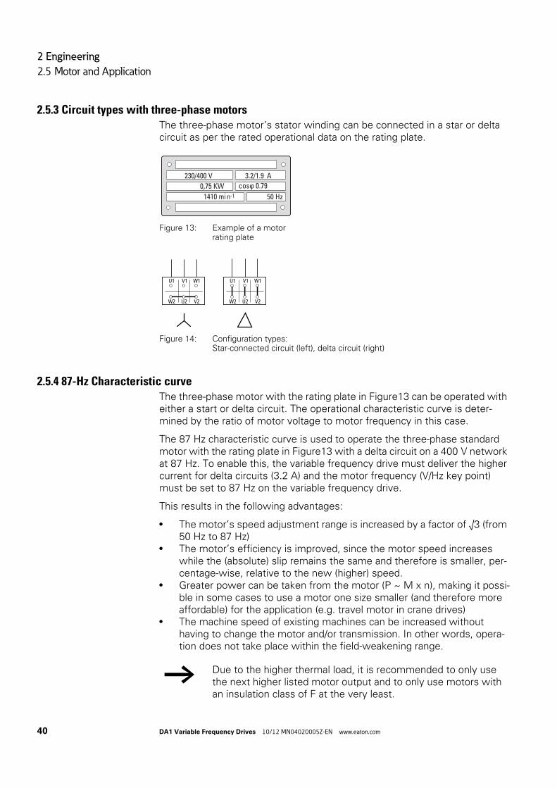
2.5.3 Circuit types with three-phase motorsThe three-phase motor’s stator winding can be connected in a star or delta circuit as per the rated operational data on the rating plate.
Figure 13: Example of a motorrating plate
Figure 14: Configuration types:Star-connected circuit (left), delta circuit (right)
2.5.4 87-Hz Characteristic curveThe three-phase motor with the rating plate in Figure13 can be operated with either a start or delta circuit. The operational characteristic curve is deter-mined by the ratio of motor voltage to motor frequency in this case.
The 87 Hz characteristic curve is used to operate the three-phase standard motor with the rating plate in Figure13 with a delta circuit on a 400 V network at 87 Hz. To enable this, the variable frequency drive must deliver the higher current for delta circuits (3.2 A) and the motor frequency (V/Hz key point) must be set to 87 Hz on the variable frequency drive.
This results in the following advantages:
• The motor’s speed adjustment range is increased by a factor of √3 (from 50 Hz to 87 Hz)
• The motor’s efficiency is improved, since the motor speed increases while the (absolute) slip remains the same and therefore is smaller, per-centage-wise, relative to the new (higher) speed.
• Greater power can be taken from the motor (P ~ M x n), making it possi-ble in some cases to use a motor one size smaller (and therefore more affordable) for the application (e.g. travel motor in crane drives)
• The machine speed of existing machines can be increased without having to change the motor and/or transmission. In other words, opera-tion does not take place within the field-weakening range.
1410 mi n
230/400 V 3.2/1.9 A
50 Hz-1
0,75 KW cos ϕ 0.79
U1 V1 W1
W2 U2 V2
U1 V1 W1
W2 U2 V2
→ Due to the higher thermal load, it is recommended to only use the next higher listed motor output and to only use motors with an insulation class of F at the very least.

2 Engineering
2.5 Motor and Application
DA1 Variable Frequency Drives 10/12 MN04020005Z-EN www.eaton.com 41
Figure 15: V/Hz characteristic curvefor the rating plate of the motor from → Figure 13
a Star connection: 400 V, 50 Hz
b Delta circuit: 230 V, 50 Hz
c Delta connection: 400 V, 87 Hz
The following Tabelle 3 shows the allocation of possible variable frequency drives depending on the mains voltage and the type of circuit.
Table 3: Assignments between variable frequency drives and V/Hz characteristic curve (→ Figure 15)
→ If using 2 pole motors (p = 1), the high speed of approximately 5,000 rpm must be taken into account. Consult the manufac-turer’s specifications.
0 8750
400
U2 [V]
f [Hz]fmax
230
a c
b
Physical parameters DA1-124D3… DA1-324D3… DA1-342D2… DA1-344D1…
Rated operational current 4.3 A 4.3 A 2.2 A 4.1 A
Mains voltage 1 AC 230 V 3 AC 230 V 3 AC 400 V 3 AC 400 V
V/f-characteristic curve ② ② ① ③
Motor circuit Delta circuit (230 V) Delta circuit (230 V) Star-connected circuit (400 V)
Delta circuit (230 V)
Motor current 3.5 A 3.5 A 2.0 A 3.5 A
Motor voltage 3 AC 0 - 230 V 3 AC 0 - 230 V 3 AC 0 - 400 V 3 AC 0 - 400 V
Motor speed 1430 min-1 1430 min-1 1430 min-1 2474 min-1 1)
Motor frequency 50 Hz 50 Hz 50 Hz 87 Hz1)
1) Note the permitted limit values of the motor!

2 Engineering
2.5 Motor and Application
42 DA1 Variable Frequency Drives 10/12 MN04020005Z-EN www.eaton.com
2.5.5 Bypass operationWhen it is necessary to be able to power the motor directly with mains volt-age independently from the variable frequency drive (bypass operation), the branches must be mechanically interlocked.
Figure 16: Bypass motor control (example)
NOTICE
The system may only switch (S1) between the variable fre-quency drive (T1) and mains voltage (see Figure16) while in a de-energized state.
CAUTION
The variable frequency drive’s outputs (U, V, W) must not be connected to the mains voltage (destruction risk, fire hazard).
→ When running the motor directly with mains voltage, protective measures (circuit-breaker with thermal overload protection ① or overload relay ②) against overload must be in place.
→ Contactors and switches (S1) in the variable frequency drive out-put and for the direct start must be designed based on utilization category AC-3 for the rated operational current of the motor.
Q1
I> I>I>
Q11
S1
M1
T1
M 3h
L1 L2 L3
L1 L2 L3
U V W
a
b

2 Engineering
2.5 Motor and Application
DA1 Variable Frequency Drives 10/12 MN04020005Z-EN www.eaton.com 43
2.5.6 Connecting EX motorsThe following aspects must be taken into account when connecting explo-sion-proof motors:
• The variable frequency drive must be installed outside the EX area.• All applicable industry-specific and country-specific regulations for haz-
ardous locations (ATEX 100a) must be complied with.• The specifications and instructions provided by the motor’s manufac-
turer with regard to operation with a variable frequency drive – e.g., whether motor reactors (dV/dt limiting) or sinusoidal filters are required – must be taken into account.
• Temperature monitors in the motor windings (thermistor, Thermo-Click) must not be connected directly to the variable frequency drive, but instead must be connected through a relay approved for the hazardous location (e.g. EMT6).
2.5.7 Sinusoidal filterSinusoidal filters are connected in the output of a variable frequency drive.
Figure 17: Circuit Diagram of a sinusoidal filter
The sinusoidal filter removes high-frequency components above the set resonance frequency from the variable frequency drive output voltage (U2).This reduces the conducted and radiated emission.
a Without sinusoidal filter
b With sinusoidal filter
f: Rotating field frequency
n: Order of harmonics
Figure 18: High frequency components of the output voltage
U2
U ∼
1U2
1V2
1W2
PE
1U1
1V1
1W1
PE
M3 ~
①
②
f2
5 10 15 20 25 30 35 40 45

2 Engineering
2.5 Motor and Application
44 DA1 Variable Frequency Drives 10/12 MN04020005Z-EN www.eaton.com
The output voltage of the sinusoidal filter (U~) achieves a sinusoidal shape with a slight superimposed ripple voltage.
The THD factor of the sinusoidal voltage is normally 5 to 10 %.
Figure 19: Output voltage to motor U2: Variable frequency drive output voltageU~: Simulated sinusoidal voltage
Advantages of sinusoidal filters:
• Long motor cable lengths with reduced conducted and radiated inter-ference
• Reduced motor losses and noise• Longer motor lifespan
Disadvantages of sinusoidal filters:
• Voltage drop of up to 9 % caused by system(approx. 36 V if U2 = 400 V)
• higher heat dissipation,• A fixed pulse frequency is required• Require more space inside the control panel
NOTICE
Sinusoidal filters must only be used with permanently set pulse frequencies.
U∼
U2

3 Installation
3.1 Introduction
DA1 Variable Frequency Drives 10/12 MN04020005Z-EN www.eaton.com 45
3 Installation
3.1 IntroductionThis chapter explains how to install and electrically connect DA1 series vari-able frequency drives.
3.2 MountingThe instructional leaflets in this section are meant to show how to install the device in a suitable enclosure for devices with protection type IP20 in compli-ance with standard EN 60529 and/or any other applicable local regulations.
• The enclosures must be made of a material with high thermal conductiv-ity.
• If a control panel with ventilation openings is used, the openings must be located above and below the variable frequency drive in order to allow for proper air circulation. The air should come in from below the variable frequency drive and leave above it.
• If the environment outside the control panel contains dirt particles (e.g., dust), a suitable particulate filter must be placed on the ventilation open-ings and forced ventilation must be used. The filters must be maintained and cleaned if necessary.
• An appropriate enclosed control panel (without ventilation openings) must be used in environments containing large percentages or amounts of humidity, salt, or chemicals.
→ While mounting and/or assembling the variable frequency drive, cover all ventilation slots in order to ensure that no foreign bod-ies can enter the device.
→ Perform all installation work with the specified tools and without the use of excessive force.

3 Installation
3.2 Mounting
46 DA1 Variable Frequency Drives 10/12 MN04020005Z-EN www.eaton.com
3.2.1 Mounting positionDA1 series variable frequency drives are designed to be mounted vertically. The maximum permissible inclination is 30°.
Figure 20: Mounting position
3.2.2 Cooling measuresIn order to guarantee sufficient air circulation, enough thermal clearance must be ensured according to the frame size (rating) of the variable fre-quency drive.
Figure 21: Space for air-cooling
≦ 30º
≦ 30º
≦ 30º
≦ 30º
b
c
a
c
a
L2/N L3DC- L1/L
DC+ BR U V W
1 2 3 4 5 6 7 8 9 10 11 12 13
14 15 16 17 18
COM
L2/N L3DC- L1/L
DC+ BR U V W
1 2 3 4 5 6 7 8 9 10 11 12 13
14 15 16 17 18
COM

3 Installation
3.2 Mounting
DA1 Variable Frequency Drives 10/12 MN04020005Z-EN www.eaton.com 47
Table 4: Minimum clearance and required cooling air
The values in 4 are recommended values for an ambient air temperature of up to +50 °C, an installation altitude of up to 1000 m, and a pulse frequency of up to 8 kHz.
Figure 22: Minimum required clearancein front of the variable frequency drive
When variable frequency drives with internal fans are installed vertically over each other, an air baffle must be placed between the devices. Failure to do so may expose the device on top to a thermal overload caused by the guided air flow (device fan).
Size a b c d Air through-put
[mm] [in] [mm] [in] [mm] [in] [mm] [in] [m3/h] [ft3/min]
FS2 50 1.97 46 1.81 75 2.95 75 2.95 18.7 11
FS3 50 1.97 52 2.05 100 3.94 100 3.94 44.2 26
FS4 10 0.39 71 2.8 200 7.87 200 7.87 – –
FS5 10 0.39 70 2.76 200 7.87 200 7.87 – –
FS6 10 0.39 140 5.52 200 7.87 200 7.87 – –
FS7 10 0.39 140 5.52 200 7.87 200 7.87 – –
→ Typical heat loss makes up about 3 % of the operational load conditions.
→ Please note that the mounting makes it possible to open and close the control signal terminal covers without any problems.
≧ 15 mm
(≧ 0.59”)
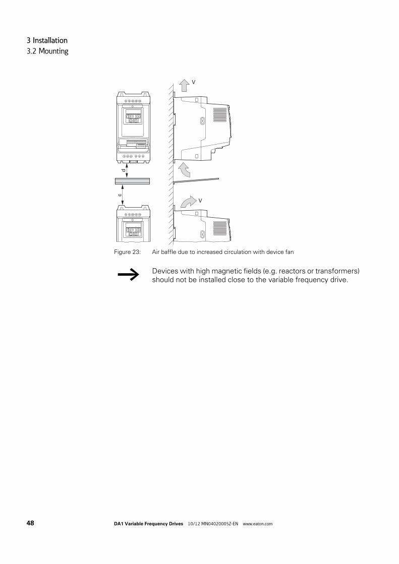
3 Installation
3.2 Mounting
48 DA1 Variable Frequency Drives 10/12 MN04020005Z-EN www.eaton.com
Figure 23: Air baffle due to increased circulation with device fan
→ Devices with high magnetic fields (e.g. reactors or transformers) should not be installed close to the variable frequency drive.
dc
V
V

3 Installation
3.2 Mounting
DA1 Variable Frequency Drives 10/12 MN04020005Z-EN www.eaton.com 49
3.2.3 Control panel installation
Figure 24: Control panel dimensioning
Calculation of control panel surface:
A =PV
[m2]ΔT x K
A = Control panel surface [m2] calculated according to IEC 890)
PV = Total heat dissipation [W] of all fitted devices
ΔT = Temperature difference [K], (default value = 5.5 K)
K = Heat transfer coefficient [W/(m2 x K)](standard value = 5.5 for steel control panels)
L1/L L2/N L3
DC-
U
DC+ BR
1 2 3 4 5 6 7 8 9 10 11 12 13
14 15 16 17 18
COM
V W
d
d
bc
a

3 Installation
3.2 Mounting
50 DA1 Variable Frequency Drives 10/12 MN04020005Z-EN www.eaton.com
3.2.4 FixingVariable frequency drives with frame sizes of FS2 and FS3 can be fastened with screws or on a mounting rail. Sizes FS4 to FS8 can only be fastened using screws.
3.2.4.1 Fixing with screws
Figure 25: Mounting dimensions
→ Install the variable frequency drive only on a nonflammable mounting base (e.g., on a metal plate).
→ Dimension and weight specifications for the DA1 variable fre-quency drive can be found in the appendix (→ Page 209).
→ The number and layout of required mounting dimensions a1 and b1, the tightening torque for the screws, etc. are listed in → Section 9.2, “Dimensions and frame size“.
→ Use screws with a washer and split washer with the permissi-ble tightening torque in order to protect the enclosure and safely and reliably mount the device.
c
c1
EMC
VAR
b1a1

3 Installation
3.2 Mounting
DA1 Variable Frequency Drives 10/12 MN04020005Z-EN www.eaton.com 51
Figure 26: Mounting preparation
First fit the screws at the specified positions, mount the variable fre-quency drive and then fully tighten all screws.
3.2.4.2 Fixing on mounting railsAs an alternative to screw mounting, DA1 variable frequency drives of sizes FS2 and FS3 can also be mounted on a mounting rail as per IEC/EN 60715.
Figure 27: Mounting rail conforming with IEC/EN 60715
To do this, place the variable frequency drive on the mounting rail from above [1] and press it down until it snaps into place [2].
→ The permitted maximum tightening torque for the fixing screws is 1.3 Nm.
1
2
3
b1
a1
25 35
17.515

3 Installation
3.2 Mounting
52 DA1 Variable Frequency Drives 10/12 MN04020005Z-EN www.eaton.com
Figure 28: Fixing to the mounting rail
Dismantling from mounting rails
To remove the device, push down the spring-loaded clip. A cutout marked on the lower edge of the device is provided for this purpose. A flat-bladed screwdriver (blade width 5 mm) is recommended for push-ing down the clip.
Figure 29: Dismantling from mounting rails
2
1
EMC
VAREMC
VAR
2
1
3
EMC
VAR
f 5 mm(f 0.197“)

3 Installation
3.3 EMC installation
DA1 Variable Frequency Drives 10/12 MN04020005Z-EN www.eaton.com 53
3.3 EMC installation
The responsibility to comply with the legally stipulated limit values and thus the provision of electromagnetic compatibility is the responsibility of the end user or system operator. This operator must also take measures to minimize or remove emission in the environment concerned (→ Figure 11, page 37). He must also utilize means to increase the interference immunity of the devices of the system.
In a magnet system (PDS) with variable frequency drives, you should take measures for electromagnetic compatibility (EMC) while doing your engi-neering, since changes or improvements to the installation site, which are required in the installation or while mounting, are normally associated with additional higher costs as well.
The technology and system of a variable frequency drive cause the flow of high frequency leakage current during operation. All grounding measures must therefore be implemented with low impedance connections over a large surface area.
With leakage currents greater than 3.5 mA, in accordance with VDE 0160 or EN 60335, either
• the cross-sectional area of the protective conductor must be ≧ 10 mm2,• The protective conductor must be open-circuit monitored, or• the second protective conductor must be fitted.
For an EMC-compliant installation, we recommend the following measures:
• Installation of the variable frequency drive in a metallically conductive housing with a good connection to ground,
• screened motor cables (short cables).
3.3.1 EMC measures in the control panelFor the EMC-compatible installation, connect all metallic parts of the device and the switching cabinet together over broad surfaces and so that high-fre-quencies will be conducted. Mounting plates and control panel doors should make good contact and be connected with short HF-drain wires. Avoid using painted surfaces (Anodized, chromized). An overview of all EMC measures is provided in Figure31 on Page 53.
→ Ground all conductive components and housings in a magnet system using as short a line as possible with the greatest possi-ble cross-section (Cu-drain wire).
→ Install the variable frequency drive as directly as possible (with-out spacers) on a metal plate (mounting plate).
→ Route mains and motor cables in the switch cabinet as close to the ground potential as possible. This is because free moving cables act as antennas.

3 Installation
3.3 EMC installation
54 DA1 Variable Frequency Drives 10/12 MN04020005Z-EN www.eaton.com
3.3.2 EarthingThe protective earth (PE) in the control panel should be connected from the mains supply to a central earth point (mounting plate, system earth). The PE conductor's cross-sectional area must be at least as large as that of the incoming mains supply cable.
Every variable frequency drive must be individually connected to the power supply system's protective earth directly at the location of installation (sys-tem earthing). This protective earth must not pass through any other devices.
All protective conductors should be routed in a star topology starting from the central earth point, and all of the drive system's conductive components (variable frequency drive, motor reactor, motor filter, main choke) should be connected.
The earth-fault loop impedance must comply with all locally applicable indus-trial safety regulations. In order to meet UL requirements, UL-listed ring cable lugs must be used for all earth wiring connections.
3.3.2.1 Protective earthThis refers to the legally required protective earth for a variable frequency drive. An earthing terminal on the variable frequency drive, or the system earth, must be connected to a neighboring steel element in the building (beam, ceiling joist), an earth electrode in the ground, or a mains earth bus. The earth points must meet the requirements set forth by the applicable national and local industrial safety regulations and/or regulations for electrical systems.
→ When laying HF cables (e.g. shielded motor cables) or sup-pressed cables (e.g. mains supply cables, control circuit and sig-nal cables) in parallel, a minimum clearance of 300 mm should be ensured in order to prevent the radiation of electromagnetic energy. You should also use separate cable entries if there is a great difference in voltage potentials. Any necessary crossed cabling between the control signal and power cables should always be implemented at right angles (90 degrees).
→ Never lay control- or signal cables in the same duct as power cables. Analog signal cables (measured, reference and correc-tion values) must be screened.
→ Avoid ground loops when installing multiple variable frequency drives in one control panel. Make sure that all metallic devices that are to be grounded have a broad area connection with the mounting plate.

3 Installation
3.3 EMC installation
DA1 Variable Frequency Drives 10/12 MN04020005Z-EN www.eaton.com 55
3.3.2.2 Motor earthingThe motor earth must be connected to one of the earthing terminals on the variable frequency drive and to a neighboring steel element in the building (beam, ceiling joist), an earth electrode in the ground, or a mains earth bus.
3.3.2.3 Earth-fault protectionA fault current to earth can be produced by variable frequency drives due to their system characteristics. DA1 series variable frequency drives have been designed in such a way that the smallest possible fault current will be pro-duced in compliance with standards applicable worldwide. This fault current must be monitored by a residual current device (RCD, type B).
3.3.3 EMC screw
Figure 30: EMC and VAR screws in a DA1variable frequency drive with protection type IP20
Due to their system characteristics, variable frequency drives with an internal EMC filter will produce a larger fault current to earth than devices without a filter. For applications in which this larger leakage current may cause mal-function messages or disconnections (residual current device), the EMC fil-ter’s internal protective earth can be disconnected (remove the EMC screw to do this). Local EMC regulations must be taken into account when doing so. If necessary, a specific low-leakage-current EMC filter must be con-nected upstream.
NOTICE
The screw labeled EMC must not be manipulated as long as the variable frequency drive is connected to the mains.
→ The EMC screw galvanically connects the EMC filter’s capaci-tors to earth. The screw must be screwed in all the way to the stop (factory setting) in order for the variable frequency drive to comply with the EMC standard.
EMC
L3UL2/N
L1/L
VAR
PH1
M3
20 mm (0.79")
EMC
VAR

3 Installation
3.3 EMC installation
56 DA1 Variable Frequency Drives 10/12 MN04020005Z-EN www.eaton.com
In connections to isolated power sources (IT networks), the EMC screw should be removed. The earth fault monitors required for IT networks must be suitable for operation with power electronic devices (IEC 61557-8).
3.3.4 VAR screwDA1 series variable frequency drives are equipped with an overvoltage filter for the input supply voltage that is designed to protect the devices from noise pulses in the mains voltage. Pulse spikes are typically caused by light-ning strikes or by switching operations in other high-power devices on the same supply.
If high potential tests are performed on a system, these overvoltage protec-tion components may cause the system to fail the test. In order to make it possible to perform this type of hipot tests, the overvoltage protection com-ponents can be disconnected by removing the VAR screw. The screw must be screwed back in after the high potential tests are performed and the test must then be repeated. The system must then fail the test, indicating that the overvoltage protection components have been reconnected.
3.3.5 Screen earth kitCables that are not screened work like antennas (sending, receiving).
The effectiveness of the cable shield depends on a good shield connection and a low shield resistance.
NOTICE
The screw labeled VAR (→ Figure 30, page 55) must not be manipulated as long as the variable frequency drive is con-nected to the mains.
→ For a proper EMC connection, cables emitting interference (e.g. motor cables) and susceptible cables (analog signal and mea-surement values) must be screened and laid separately from each other.
→ Use only shields with tinned or nickel-plated copper braiding. Braided steel shields are unsuitable.
→ Control and signal lines (analog, digital) should always be grounded on one end, in the immediate vicinity of the supply voltage source (PES).
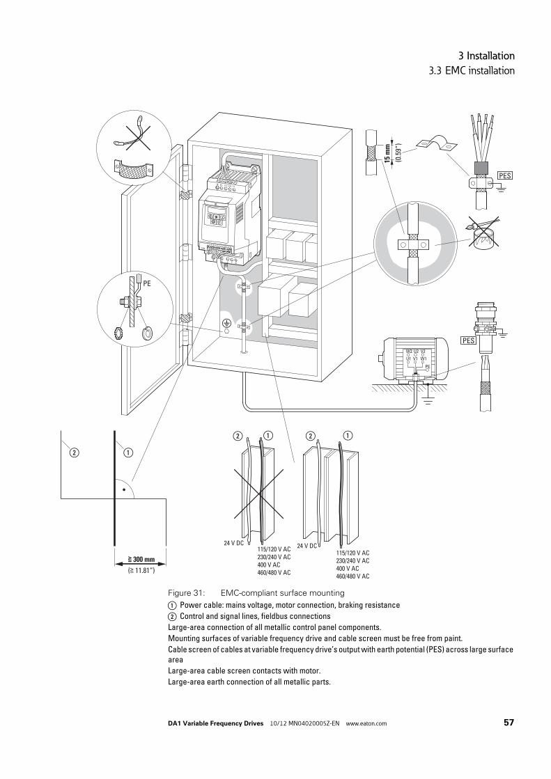
3 Installation
3.3 EMC installation
DA1 Variable Frequency Drives 10/12 MN04020005Z-EN www.eaton.com 57
Figure 31: EMC-compliant surface mounting
a Power cable: mains voltage, motor connection, braking resistance
b Control and signal lines, fieldbus connections
Large-area connection of all metallic control panel components.
Mounting surfaces of variable frequency drive and cable screen must be free from paint.
Cable screen of cables at variable frequency drive’s output with earth potential (PES) across large surface area
Large-area cable screen contacts with motor.
Large-area earth connection of all metallic parts.
L1/L L2/N L3
DC-
U
DC+ BR
1 2 3 4 5 6 7 8 9 10 11 12 13
14 15 16 17 18
COM
V W
PE
W2 U2 V2
U1 V1 W1
PE
24 V DC
②
②
①
① ② ①
≧ 300 mm
(≧ 11.81“)
115/120 V AC230/240 V AC400 V AC460/480 V AC
24 V DC
115/120 V AC230/240 V AC400 V AC460/480 V AC
PES
15
mm
(0.5
9“)
PES

3 Installation
3.4 Electrical Installation
58 DA1 Variable Frequency Drives 10/12 MN04020005Z-EN www.eaton.com
3.4 Electrical Installation
CAUTION
Carry out the wiring work only after the variable frequency drive has been correctly mounted and secured.
DANGER
Electric shock hazard - risk of injuries!Carry out wiring work only if the unit is de-energized.
NOTICE
Fire hazard!Only use cables, protective switches, and contactors that fea-ture the indicated permissible nominal current value.
NOTICE
In DA1 variable frequency drives, earth leakage currents are greater than 3.5 mA (AC). According to product standard IEC/EN 61800-5-1, an additional equipment grounding conductor must be connected, or the cross-section of the equipment grounding conductor must be at least 10 mm2.
DANGER
The components in the variable frequency drive’s power section remain energized up to five (5) minutes after the supply voltage has been switched off (intermediate circuit capacitor discharging time).
Pay attention to hazard warnings!.
→ Complete the following steps with the specified tools and with-out using force.
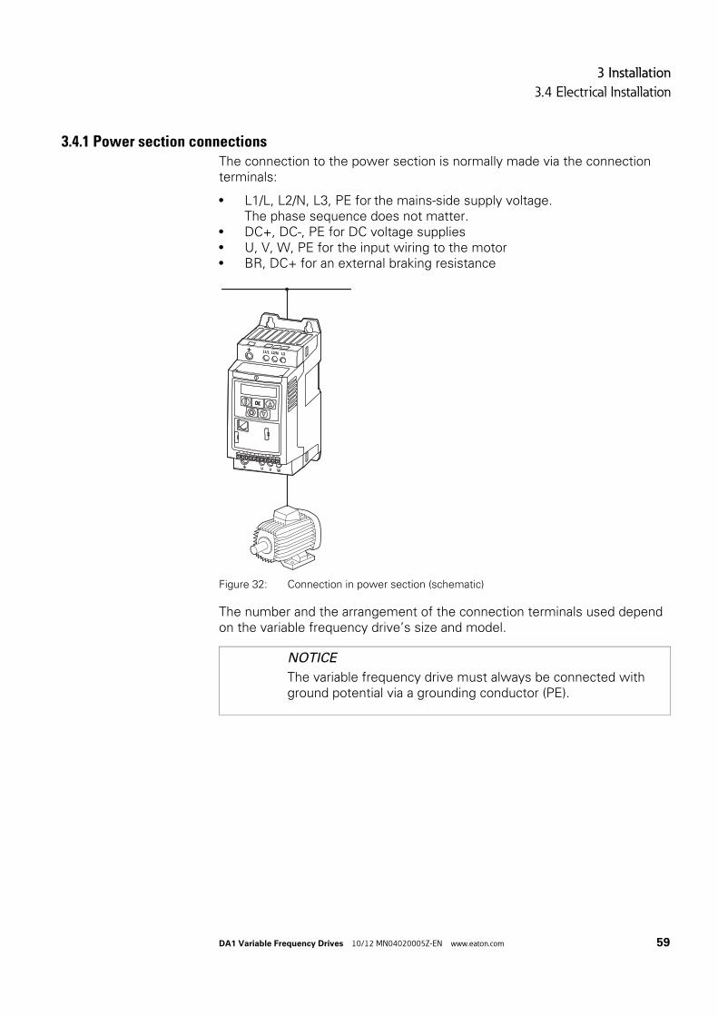
3 Installation
3.4 Electrical Installation
DA1 Variable Frequency Drives 10/12 MN04020005Z-EN www.eaton.com 59
3.4.1 Power section connectionsThe connection to the power section is normally made via the connection terminals:
• L1/L, L2/N, L3, PE for the mains-side supply voltage.The phase sequence does not matter.
• DC+, DC-, PE for DC voltage supplies• U, V, W, PE for the input wiring to the motor• BR, DC+ for an external braking resistance
Figure 32: Connection in power section (schematic)
The number and the arrangement of the connection terminals used depend on the variable frequency drive’s size and model.
NOTICE
The variable frequency drive must always be connected with ground potential via a grounding conductor (PE).
L1/L L2/N L3
U V W
1 2 3 4 5 6 7 8 9 10 11
L1/L L2/N L3
U V W
1 2 3 4 5 6 7 8 9 10 11

3 Installation
3.4 Electrical Installation
60 DA1 Variable Frequency Drives 10/12 MN04020005Z-EN www.eaton.com
3.4.1.1 connection cables
Figure 33: connection cables
Table 5: Stripping lengths in the power section
Mains Motor DC link, Brake Resistor
PE
A1
PE A1
PEA1
Size A1mm (in)
FS2 8 (0.3)
FS3 8 (0.3)
FS4 –
FS5 –
FS6 –
FS7 –
Mains = Electrical supply system,Motor = Motor connection,DC-Link = Internal DC link,Brake Resistor = Braking resistance

3 Installation
3.4 Electrical Installation
DA1 Variable Frequency Drives 10/12 MN04020005Z-EN www.eaton.com 61
3.4.1.2 Terminals in power section
Table 6: Terminations
3.4.1.3 connection cablesThe screened cables between the variable frequency drive and the motor should be as short as possible.
Connect the screening, on both sides and across a large area (360° over-lap), to the protective earth (PE) . The power screening’s protective earth (PES) connection should be in the immediate proximity of the vari-able frequency drive.and directly on the motor terminal box.
Prevent the screening from becoming unbraided, e.g. by pushing the opened plastic sheath over the end of the screening or with a rubber grommet on the end of the screening. As an alternative, in addition to a broad area cable clip, you can also twist the shielding braid at the end
Framesize
Terminations Description
FS2FS3FS4FS5FS6FS7
Connection with single-phase supply voltage:• DA1-12… (230 V)
Connection with three-phase supply voltage:• DA1-32… (230 V)• DA1-34… (400 V, 480 V)
Motor connection for three-phase motors:• DA1-12… (230 V)• DA1-32… (230 V)• DA1-34… (400 V, 460 V)
optional: External braking resistance (RB)
DC- L1/L L2/N L3
L NPE
DC- L1/L L2/N L3
L1 L2PE L3
PES
DC+ BR U V W
RB
M3
→ In sizes FS2 and FS3, the DC+, DC-, and BR terminals are cov-ered with plastic covers at the factory. They can be uncovered if necessary.
In all single-phase supply variable frequency drives terminal L3 is covered with a plastic cover. Do not uncover this terminal!

3 Installation
3.4 Electrical Installation
62 DA1 Variable Frequency Drives 10/12 MN04020005Z-EN www.eaton.com
and connect to protective ground with a cable clip. To prevent EMC dis-turbance, this twisted shielding connection should be made as short as possible (→ Figure 35).
Figure 34: Screened connection cable
Figure 35: Connection with twisted cable screenRecommended value for twisted cable shielding:b ≧ 1/5 a
Screened, four-wire cable is recommended for the motor cables. The green-yellow line of this cable connects the protective ground connections from the motor and the variable frequency drive and therefore minimizes the equaliz-ing current loads on the shielding braid.
15 mm(0.59’’)
PES

3 Installation
3.4 Electrical Installation
DA1 Variable Frequency Drives 10/12 MN04020005Z-EN www.eaton.com 63
The following figure shows the construction of a four-wire, screened motor line (recommended specifications).
Figure 36: Four-core screened motor supply cable
a Cu shield braid
b PVC outer casing
c Drain wire (copper strands)
d PVC core insulation, 3 x black, 1 x green–yellow
e Textile and PVC fillers
If there are additional subassemblies in a motor feeder (such as motor con-tactors, overload relays, motor reactor, sinusoidal filters or terminals), the shielding of the motor cable can be interrupted close to these subassemblies and connected to the mounting plate (PES) with a large area connection. Free or non-screened connection cables should not be any longer than about 300 mm.
3.4.1.4 Configuration and terminal capacitiesThe connection terminals’ layout depends on the size of the power section.
The cross-sections to be used in the connections and the tightening torques for screws are listed in the following.
Table 7: Cross-sectional areas and tightening torques
ba
e dc
M3
Size mm2 AWG MM in N/m MM
FS2 …FS7
0.2 - 2.5 24 - 12 8 0.31 0.5 0.6 x 3.5
PH2
1 Nm
(8.85 lb-in)

3 Installation
3.4 Electrical Installation
64 DA1 Variable Frequency Drives 10/12 MN04020005Z-EN www.eaton.com
3.4.2 Connection on control sectionThe 13-terminal and 5-terminal strips have a plug-in design and are mounted in the front.
Figure 37: Location of plug-in control signal terminals
The control cables should be screened and twisted. The screening is applied on one side in the proximity of the variable frequency drive (PES).
Figure 38: Preventing the screening from becoming unbraided
Alternatively, in addition to the broad area cable clip, you can also twist the shielding braid at the end and connect to the protective ground with a cable lug. To prevent EMC disturbance, this twisted shielding connection should be made as short as possible (→ Figure 35, page 62).
Prevent the screen from becoming unbraided at the other end of the control cable, e.g. by using a rubber grommet. The shield braid must not make any connection with the protective ground here because this would cause prob-lems with an interference loop.
→ Prevent the screening from becoming unbraided, i.e. by pushing the separated plastic covering over the end of the shielding or with a rubber grommet on the end of the screening.
1 2 3 4 5 6 7 8 9 10 11 12 13
14 15 16 17 18
15 m
m(0.59’’) PES

3 Installation
3.4 Electrical Installation
DA1 Variable Frequency Drives 10/12 MN04020005Z-EN www.eaton.com 65
Figure 39: Example for an insulated end of the control cable
3.4.2.1 Arrangement and designation of the control signal terminals
The following figure shows the layout and designations for the DA1 variable frequency drive's control signal terminals.
Figure 40: Arrangement and factory designations for the control signal terminals
5 6 71 2 3
+10 V AI1 0 V+24 V DI1 DI2
PE
PES
PES
M4K7
R1
M
FWD REV
ZB4-102-KS1
15
mm
(0.5
9”)
M4
2Cu 2.5 mm
1 2
3
≦ 2
0 m
(≦ 6
5.62
ft)
ESD measuresDischarge yourself on a grounded surface before touching the control signal terminals and the circuit board to prevent damage through electrostatic discharge.
1 2 3 4 5 6 7 8 9 10 11
+24
DI1
AI1
10
V
DI2
DI3
AO
10
VD
I4A
O1
12
STO
+
13
STO
-
15 16 17
K14
14
K11
K12
K23
K24
18
+10
V

3 Installation
3.4 Electrical Installation
66 DA1 Variable Frequency Drives 10/12 MN04020005Z-EN www.eaton.com
3.4.2.2 Functions of control signal terminalsThe functions that are set in the ex-factory and the electrical connection data of control signal terminals are listed in the following table.
Table 8: Factory-set functions of the control terminals
Terminal Signal Description Default settings
1 +24 V Control voltage for DI1 - DI5, output (+24 V)
Maximum load 100 mA,Reference potential 0 V
–
2 DI1 Digital input 1 8 - +30 V (High, Ri > 6 kΩ) Start enable FWD1)
3 DI2 Digital Input 2 8 - +30 V (High, Ri > 6 kΩ) Start enable REV1)
4 DI3 Digital Input 3 8 - +30 V (High, Ri > 6 kΩ) Fixed frequency FF1/FF21)
5 +10 V Reference voltage,Output (+10 V)
Maximum load 10 mAReference potential 0 V
–
6 AI1DI4
Analog input 1Digital Input 5
• Analog: 0 - +10 V (Ri > 72 kΩ)0/4 - 20 mA (RB = 500 Ω)Can be switched with parameter P2-30
• digital: 8 - 30 V (high)
Frequency reference value1)
7 0 V Reference potential 0 V = connection terminal 9 –
8 AO1DO1
Analog output 1Digital output 1
• Analog: 0 - +10 V, maximum 20 mACan be switched with parameter P2-11
• digital: 0 - +24 V
Output frequency1)
9 0 V Reference potential 0 V = connection terminal 7 –
10 DI4AI2
Digital Input 4Analog input 2
• Analog: 0 - +10 V (Ri > 72 kΩ)0/4 - 20 mA (RB = 500 Ω)Can be switched with parameter P2-30
• digital: 8 - 30 V (high)
Fixed frequency FF21)
11 AO2DO2
Analog output 2Digital output 2
• Analog: 0 - +10 V, maximum 20 mACan be switched with parameter P2-13
• digital: 0 - +24 V
Output current1)
12 STO+ Safe Torque Off + Enable = +24 V –
13 STO- Safe Torque Off - Enable = 0 V –
14 K11 Relay 1, changeover contact Maximum switching load:250 V AC/6 A or 30 V DC/5 A
active = FAULT1)
15 K14 Relay 1, changeover contact (N/O) Maximum switching load:250 V AC/6 A or 30 V DC/5 A
active = FAULT1)
16 K12 Relay 1, changeover contact (N/C) Maximum switching load:250 V AC/6 A or 30 V DC/5 A
active = FAULT1)
17 K23 Relay 2, N/O contact Maximum switching load:250 V AC/6 A or 30 V DC/5 A
active = FAULT1)
18 K24 Relay 2, N/O contact Maximum switching load:250 V AC/6 A or 30 V DC/5 A
active = FAULT1)
1) programmable function

3 Installation
3.4 Electrical Installation
DA1 Variable Frequency Drives 10/12 MN04020005Z-EN www.eaton.com 67
The DA1 variable frequency drive has four control inputs (control signal termi-nals 2, 3, 4, 6 and 10). Three of these are permanently set as digital control inputs; while the others can be set to work as digital or analog control inputs.
The variable frequency drive comes with the following default setting:
• Control signal terminal 2 as digital input 1 (DI1),• Control signal terminal 3 as digital input 2 (DI2),• Control signal terminal 4 as digital input 3 (DI3),• Control signal terminal 6 as analog input 1 (AI1).• Control signal terminal 10 as digital input 4 (DI4),
Control signal terminals 8 and 11 can be used as digital or analog outputs. They are set up as analog outputs (AO) in the default configuration that comes with the variable frequency drive when it is delivered.
Figure 41: Control signal terminals (digital / analog)
2
DI1
FWD
+24
V
4
DI3
FF1/
FF2
3
DI2
REV
10
DI4
(AI2
)FF
2
1
+24
V O
ut<
100
mA
6
AI1
(DI5
)
CPU
8
AO
1(D
O1)
f-O
ut0.
..+10
V/2
0 m
A
f-S
oll
0...+
10 V
/20
mA
11
AO
2(D
O2)
A-O
ut0.
..+10
V/2
0 m
A

3 Installation
3.4 Electrical Installation
68 DA1 Variable Frequency Drives 10/12 MN04020005Z-EN www.eaton.com
3.4.2.3 Analog input signalsDepending on how parameters P1-12 and P1-13 are set, control signal termi-nals 6 (AI1) and 10 (AI2) can be connected to analog signals.
• 0 - +10 V• 0 - 10 V with scaling and operating direction change• 0 - 20 mA• 4 - 20 mA or 20 - 4 mA with open-circuit monitoring (< 3 mA)
3.4.2.4 Analog output signalAn analog signal is available at control signal terminals 8 and 11. These out-puts can handle a maximum load of 20 mA. The output signal is configured using parameters P2-11 (AO1) and P2-13 (AO2) (→ Table 10, Page 87).
Parameters P2-12 (AO1) and P2-14 (AO2) are used to configure the formats for the analog inputs:
Figure 42: Analog output (AO) (connecting example)
→ The assignments between the values and functions are described in → Section 6.2.2, “Analog Input (AI)“, page136.
→ Control signal terminals 7 and 9 are the common 0 V reference potential for all analog and digital input signals.
Parameter value
Configuration
0 0 - 10 V
1 10 - 0 V
2 0 - 20 mA
3 20 - 0 mA
4 4 - 20 mA
5 20 - 4 mA
→ Control signal terminals 7 and 9 are the common 0 V reference potential for all analog and digital output signals.
9
0...+
10 V
AO
8
OV
< 20
mA
f-O
ut
-
+

3 Installation
3.4 Electrical Installation
DA1 Variable Frequency Drives 10/12 MN04020005Z-EN www.eaton.com 69
3.4.2.5 Digital Input SignalsControl signal terminals 2, 3, 4, 6 and 10 all have the same function and mode of operation as digital inputs (DI1 to DI5).
A logic level of +24 V (positive logic) is used:
• 8 - +30 V = High (logic “1“)• 0 - +4 V = Low (logic “0“)
The internal control voltage from control terminal 1 (+24 V, maximum 100 mA) or an external voltage source (+24 V) can be used for this.The permissible residual ripple must be less than ±5 % ΔUa/Ua.
The parameter configuration and the way functions are assigned are described in → Section 6.2.1, “Digital Input (DI)“, page135.
→ Control signal terminals 7 and 9 are the common 0 V reference potential for all analog and digital input signals.

3 Installation
3.4 Electrical Installation
70 DA1 Variable Frequency Drives 10/12 MN04020005Z-EN www.eaton.com
3.4.2.6 Digital output (Transistor)Control signal terminals 8 and 11 are set up as analog outputs (AO) in the default configuration that comes with the variable frequency drive when it is delivered. Parameters P2-11 and P2-13 (→ Table 10, Page 87) can be used to set them up as digital outputs (DO) instead.
Transistor outputs DO1 and DO2 can deliver a digital signal via control signal terminals 8 and 11 using the device’s internal control voltage (+24 V). The maximum permissible load current is 20 mA.
Figure 43: Connection example (interposing relay with free-wheeling diode:ETS4-VS3; article no. 083094)
3.4.2.7 Digital Output (Relay)Control signal terminals 14, 15 (N/O), and 16 (N/C) are connected to the DA1 variable frequency drive’s internal relay 1 in a potential-free manner.
Control signal terminals 17 and 18 are connected to internal relay 2 (N/O) in a potential-free manner.
The relay function can be configured using parameters P2-15 and P2-18 (→ Table 10, Page 87).
The electrical connection specifications for control signal terminals are:
• 250 V AC, max. 6 A• 30 V DC, max. 5 A
We recommend connecting any connected loads as follows:
→ Control signal terminals 7 and 9 are the common 0 V reference potential for all analog and digital output signals.
< 20
mA
DO
OV
8 9
+
+ 24 V
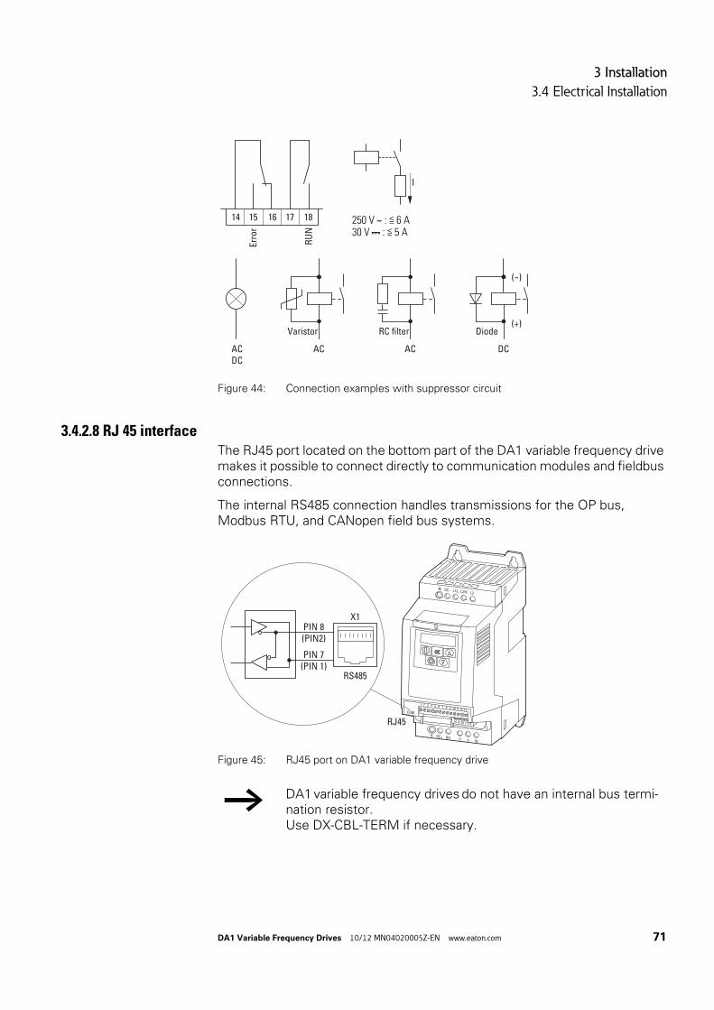
3 Installation
3.4 Electrical Installation
DA1 Variable Frequency Drives 10/12 MN04020005Z-EN www.eaton.com 71
Figure 44: Connection examples with suppressor circuit
3.4.2.8 RJ 45 interfaceThe RJ45 port located on the bottom part of the DA1 variable frequency drive makes it possible to connect directly to communication modules and fieldbus connections.
The internal RS485 connection handles transmissions for the OP bus, Modbus RTU, and CANopen field bus systems.
Figure 45: RJ45 port on DA1 variable frequency drive
250 V ∼ : ≦ 6 A30 V : ≦ 5 A
Erro
r
RU
N
16 17 1814 15
I
ACDC
AC
Varistor(+)
(-)
DC
Diode
AC
RC filter
→ DA1 variable frequency drives do not have an internal bus termi-nation resistor.Use DX-CBL-TERM if necessary.
RJ45
X1
L1/L L2/N L3
DC-
U
DC+ BR
1 2 3 4 5 6 7 8 9 10 11 12 13
14 15 16 17 18
COM
V W
PIN 8(PIN2)
PIN 7(PIN 1)
RS485

3 Installation
3.4 Electrical Installation
72 DA1 Variable Frequency Drives 10/12 MN04020005Z-EN www.eaton.com
3.4.3 Block diagramsThe following block diagrams show all the connection terminals on a DA1 variable frequency drive and their functions when in their default settings.
3.4.3.1 DA1-12…
Figure 46: DA1-12… block diagramVariable frequency drive with single-phase supply system voltage and three-phase motor connection
① External braking resistors can be connected to devices of size FS2 to FS8.
DC+
BR
DC-
3 AC 230 V
WVU
M3 ~
13
STO
-
1
+24
V O
ut<
100
mA
24 V
2D
I1FW
D
REV
FF1/
FF2
FF2
3
DI2
4
DI3
10
DI4
AI2
12
STO
+
L1/L
EMC
5
+10
V O
ut<
10 m
A
6
AI1
DI5 0 V
7L2/N
VAR
CPUSTO10
V
0 V
f-S
oll
1 AC 230 V50/60 Hz
PES
X1
①+-
15 16
Erro
r
RU
N
17 18 814 9 11
6 A
, 250
V A
C5
A, 3
0 V
DC
6 A
, 250
V A
C5
A, 3
0 V
DC
A-O
ut0 V
0 V
f-O
ut+2
4 V
DO
+24
V D
O
PIN 8(PIN2)
PIN 7(PIN 1)
RS485

3 Installation
3.4 Electrical Installation
DA1 Variable Frequency Drives 10/12 MN04020005Z-EN www.eaton.com 73
3.4.3.2 DA1-32…, DA1-34…
Figure 47: DA1-32…, DA1-34… block diagramVariable frequency drive with three-phase mains supply voltage and three-phase motor connection
① External braking resistors can be connected to devices of size FS2 to FS8.
DC+
BR
DC-
WVU
M3 ~
13
STO
-
1
+24
V O
ut<
100
mA
24 V
2
DI1
FWD
REV
FF1/
FF2
FF2
3
DI2
4
DI3
10
DI4
AI2
12S
TO+
EMC
5
+10
V O
ut<
10 m
A
6
AI1
DI5 0 V
PIN 8(PIN 2)
PIN 7(PIN 1)
7
VAR
RS485
CPUSTO
10 V
0 V
f-S
oll
PES
X1
①+-
15 16
Erro
r
RU
N
17 18 814 9 11
6 A
, 250
V A
C5
A, 3
0 V
DC
6 A
, 250
V A
C5
A, 3
0 V
DC
A-O
ut0 V
0 V
f-O
ut
L1/L L3L2/N
3 AC 230 V3 AC 400/480 V50/60 Hz
+24
V D
O
+24
V D
O

3 Installation
3.4 Electrical Installation
74 DA1 Variable Frequency Drives 10/12 MN04020005Z-EN www.eaton.com
3.4.4 Insulation testThe variable frequency drive of the DA1 series are tested, delivered and require no additional testing.
If insulation testing is required in the power circuit of the PDS, you must con-sider the following measures.
3.4.4.1 Testing the motor cable insulation Disconnect the motor cable from the connection terminals U, V and W of
the variable frequency drive and from the motor (U, V, W). Measure the insulation resistance of the motor cable between the individual phase conductors and between the phase conductor and the protective con-ductor.
The insulation resistance must be greater than 1 MΩ.
3.4.4.2 Testing the mains cable insulation Disconnect the power cable from the mains supply network and from
the connection terminals 1/L, L2/N and L3 of the variable frequency drive. Measure the insulation resistance of the mains cable between the individual phase conductors and between each phase conductor and the protective conductor.
The insulation resistance must be greater than 1 MΩ.
3.4.4.3 Testing the motor insulation Disconnect the motor cable from the motor (U, V, W) and open the
bridge circuits (star or delta) in the motor terminal box.Measure the insulation resistance of the individual motor windings. The measurement voltage must at least match the rated operating voltage of the motor but is not to exceed 1000 V.
The insulation resistance must be greater than 1 MΩ.
CAUTION
On the control signal and the connection terminals of the vari-able frequency drive, no leakage resistance tests are to be per-formed with an insulation tester.
CAUTION
Wait at least 5 minutes after switching the supply voltage off before you disconnect one of the connection terminals (L1/L, L2/N, L3, DC-, DC+, BR) of the variable frequency drive.
→ Consider the notes from the motor manufacturer in testing the insulation resistance.
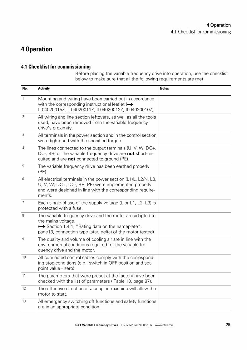
4 Operation
4.1 Checklist for commissioning
DA1 Variable Frequency Drives 10/12 MN04020005Z-EN www.eaton.com 75
4 Operation
4.1 Checklist for commissioningBefore placing the variable frequency drive into operation, use the checklist below to make sure that all the following requirements are met:
No. Activity Notes
1 Mounting and wiring have been carried out in accordance with the corresponding instructional leaflet (→ IL04020015Z, IL04020011Z, IL04020012Z, IL04020010Z).
2 All wiring and line section leftovers, as well as all the tools used, have been removed from the variable frequency drive’s proximity.
3 All terminals in the power section and in the control section were tightened with the specified torque.
4 The lines connected to the output terminals (U, V, W, DC+, DC-, BR) of the variable frequency drive are not short-cir-cuited and are not connected to ground (PE).
5 The variable frequency drive has been earthed properly (PE).
6 All electrical terminals in the power section (L1/L, L2/N, L3, U, V, W, DC+, DC-, BR, PE) were implemented properly and were designed in line with the corresponding require-ments.
7 Each single phase of the supply voltage (L or L1, L2, L3) is protected with a fuse.
8 The variable frequency drive and the motor are adapted to the mains voltage.(→ Section 1.4.1, “Rating data on the nameplate“, page13, connection type (star, delta) of the motor tested).
9 The quality and volume of cooling air are in line with the environmental conditions required for the variable fre-quency drive and the motor.
10 All connected control cables comply with the correspond-ing stop conditions (e.g., switch in OFF position and set-point value= zero).
11 The parameters that were preset at the factory have been checked with the list of parameters ( Table 10, page 87).
12 The effective direction of a coupled machine will allow the motor to start.
13 All emergency switching off functions and safety functions are in an appropriate condition.

4 Operation
4.2 Hazard warnings for operation
76 DA1 Variable Frequency Drives 10/12 MN04020005Z-EN www.eaton.com
4.2 Hazard warnings for operationPlease observe the following notes.
DANGER
Commissioning is only to be completed by qualified technicians.
DANGER
Hazardous voltage!
The safety instructions on pages I and II must be followed.
DANGER
The components in the variable frequency drive’s power section are energized if the supply voltage (mains voltage) is connected. For instance: L1/L, L2/N, L3, DC+, DC-, BR, U/T1, V/T2, W/T3 power terminals.The control signal terminals are isolated from the line power potential.There can be a dangerous voltage on the relay terminals (10, 11) even if the variable frequency drive is not being supplied with mains voltage (e.g., integration of relay contacts in control sys-tems with voltage > 48 V AC / 60 V DC).
DANGER
The components in the variable frequency drive’s power section remain energized up to five (5) minutes after the supply voltage has been switched off (intermediate circuit capacitor discharg-ing time).
Pay attention to hazard warnings!
DANGER
Following a shutdown (fault, mains voltage off), the motor can start automatically (when the supply voltage is switched back on) if the automatic restart function has been enabled (→ parameters P2-36).

4 Operation
4.3 Commissioning with control signal terminals (default settings)
DA1 Variable Frequency Drives 10/12 MN04020005Z-EN www.eaton.com 77
4.3 Commissioning with control signal terminals (default settings)DA1 variable frequency drives are set in the factory and can be started directly via the control signal terminals by connecting the motor outputs allo-cated for the mains voltage (see connection example below).
Following are a series of simplified connecting examples that use the default settings.
NOTICE
Any contactors and switchgear on the power side are not to be opened during motor operation. Inching operation using the power switch is not permitted.
Contactors and switchgear (repair and maintenance switches) on the motor side must not be opened while the motor is in operation.Inching operation of the motor with contactors and switchgear in the output of the variable frequency drive is not permitted.
NOTICE
Make sure that there is no danger in starting the motor. Discon-nect the driven machine if there is a danger in an incorrect oper-ating state.
→ If motors are to be operated with frequencies higher than the standard 50 or 60 Hz, then these operating ranges must be approved by the motor manufacturer. The motors could be dam-aged otherwise.
→ You can skip this section if you want to set up the parameters directly for optimal operation of the variable frequency drive based on the motor data (rating plate) and the application.

4 Operation
4.3 Commissioning with control signal terminals (default settings)
78 DA1 Variable Frequency Drives 10/12 MN04020005Z-EN www.eaton.com
Connecting example for three-phase motor
Connect the variable frequency drive according to the connecting exam-ple above for the simple commissioning with the specified default set-tings (see connecting example above).
The potentiometer should have a fixed resistance (connection to control sig-nal terminals 5 and 7) of at least 1 kΩ, up to a maximum of 10 kΩ. A standard fixed resistance of 4.7 kΩ is recommended.
Make sure that the enable contacts (FWD/REV) are open and the STO is con-nected correctly before switching on the mains voltage.
When the specified supply voltage is applied at the mains connection termi-nals (L1/L, L2/N, L3), the switched-mode power supply unit (SMPS) in the internal DC link will be used to generate the control voltage and light up the 7-segment LED display (STOP).
At this point, the variable frequency drive will be ready for operation (correct operating status) and in Stop mode.
Connecting example for three-phase motor Terminal designation
L1/L Single-phase power supply connection(DA1-12…)
Three-phase power supply connection(DA1-32…, DA1-34…)L2/N
L3 –
Ground connection
1 Control voltage +24 V (output, maximum 100 mA)
2 FWD, Start release clockwise rotating field
3 REV, Start release left rotating field
U Connection for three-phase ac motor(three-phase motor)
V
W
5 Setpoint value voltage +10 V (Output, maximum 10 mA)
6 Frequency reference value f-Set (Input 0 – +10 V)
7 Reference potential (0 V)
12 Safe Torque Off +
13 Safe Torque Off -
PE
PE
WVU
M3 ~
6 75
1 2 3
+24
V
FWD
0...+
10 V 0 V
+10
V
L3L1/L L2/N
L N
L3L1 L2
REV
f-S
oll
12
13
STO+
STO-
→ If the connections for the setpoint value potentiometer cannot be clearly allocated with terminals 5, 6 and 7, you should set the potentiometer to about 50 % before giving the start release (FWD/REV) for the first time.

4 Operation
4.3 Commissioning with control signal terminals (default settings)
DA1 Variable Frequency Drives 10/12 MN04020005Z-EN www.eaton.com 79
The start release is done by actuating one of the digital inputs with +24 V:
• Terminal 2: FWD = Clockwise rotating field (Forward Run)• Terminal 3: REV = Counterclockwise rotating field (Reverse Run)
The FWD and REV control commands are interlocked (exclusive OR) and require a rising voltage edge.
The frequency is shown with a minus sign with a start release with a left rotating field (REV).
You can now set the output frequency (0 - 50 Hz) and, as a result, the speed of the connected three-phase motor (0 - nMotor) by using the potentiometer via terminal 6 (0 - +10 V proportional voltage signal). The change in output frequency here is delayed based on the specified accel-eration and deceleration ramps. In the default settings, these times are set to 5 seconds and to 10 seconds from a frame size FS4.
The acceleration and deceleration ramps specify the time change for the out-put frequency: from 0 to fmax (WE = 50 Hz) or from fmax back to 0.
Figure48 shows a good example of the process, if the release signal (FWD/REV) is switched on and the maximum setpoint voltage (+10 V) is applied. The speed of the motor follows the output frequency depending on the load and moment of inertia (slip), from zero to nmax.
If the release signal (FWD, REV) is switched off during operation, the inverter is blocked immediately (STOP). The motor comes to an uncontrolled stop (see ① in Figure48). The acceleration time is set in parameter P1-03.
Figure 48: Start-Stop command with maximum setpoint value voltage
t
t
fmax ~ nmax
f
P1-03
FWDREV
+24 V
= 50 Hz
0
P1-07
①
RUN STOP

4 Operation
4.3 Commissioning with control signal terminals (default settings)
80 DA1 Variable Frequency Drives 10/12 MN04020005Z-EN www.eaton.com

5 Error messages
5.1 Introduction
DA1 Variable Frequency Drives 10/12 MN04020005Z-EN www.eaton.com 81
5 Error messages
5.1 IntroductionDA1 series variable frequency drives come with several internal monitoring functions. When a deviation from the correct operating state is detected, an error message will be displayed; in the inverter’s default settings, the relay contact will open (control signal terminals 14 and 15).
5.1.1 Error messagesThe most recent four error messages will be stored in the order in which they occurred (with the most recent one in the first place). Error messages can be read from parameter P0-13 and the P0-... monitor values.
5.1.2 Acknowledge fault (Reset)To acknowledge and reset the current error message, you can either switch off the supply voltage or press the STOP pushbutton.
5.1.2.1 Fault logThe fault log (P0-13) stores the most recent four error messages in the order in which they occurred. The most recent error message will always be shown as the first value when P0-13 is accessed. To see the remaining error messages one after the other, press the (Up) button. Their order will be indicated by means of flashing dots in the 7-segment digital display assem-bly.
→ To get more information regarding the fault, go to the “Monitor“ menu (P0-…).The values in the fault log (P0-13) will not be deleted if the vari-able frequency drive is reset to its default settings!
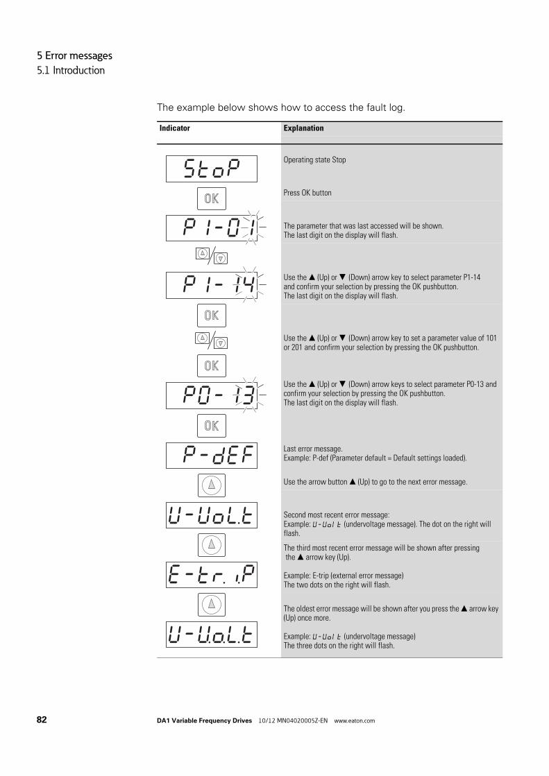
5 Error messages
5.1 Introduction
82 DA1 Variable Frequency Drives 10/12 MN04020005Z-EN www.eaton.com
The example below shows how to access the fault log.
Indicator Explanation
Operating state Stop
Press OK button
The parameter that was last accessed will be shown.The last digit on the display will flash.
Use the (Up) or (Down) arrow key to select parameter P1-14and confirm your selection by pressing the OK pushbutton.The last digit on the display will flash.
Use the (Up) or (Down) arrow key to set a parameter value of 101 or 201 and confirm your selection by pressing the OK pushbutton.
Use the (Up) or (Down) arrow keys to select parameter P0-13 and confirm your selection by pressing the OK pushbutton.The last digit on the display will flash.
Last error message.Example: P-def (Parameter default = Default settings loaded).
Use the arrow button (Up) to go to the next error message.
Second most recent error message:Example: V-Volt (undervoltage message). The dot on the right will flash.
The third most recent error message will be shown after pressing the arrow key (Up).
Example: E-trip (external error message)The two dots on the right will flash.
The oldest error message will be shown after you press the arrow key (Up) once more.
Example: V-Volt (undervoltage message)The three dots on the right will flash.

5 Error messages
5.1 Introduction
DA1 Variable Frequency Drives 10/12 MN04020005Z-EN www.eaton.com 83
5.1.3 Error listThe following table lists the failure codes, the possible causes and indicates corrective measures.
Table 9: Error messages list
Indicator Fault Code Designation Possible cause Notes
no-Flt 00 no error – –
0I-b 01 Overcurrent braking resis-tance
Brake chopper overcurrent Overcurrent in braking resistor circuitCheck the wiring to the braking resistance.Check the brake resistor value (P6-19). Make sure that the minimum resistance values are being adhered to.
OL-br 02 Braking resistor thermal overload
Braking resistance overload Increase the deceleration time (P1-04), reduce the load's moment of inertia, or connect additional braking resistors in parallel.Make sure that the minimum resistance values are being adhered to.
0- I 03 Overcurrent motor • Overcurrent at output• Motor overload• Overtemperature at heat sink
Motor with constant speed: Determine the over-load or fault.Motor starts: The load stalled or has seized, or the brake is not open.Check whether there is a star/delta motor wiring error.Motor accelerates/decelerates: The excessively short acceleration/deceleration time is requiring too much power.If P1-03 or P1-04 cannot be increased, a more powerful variable frequency drive is required.Cable fault between variable frequency drive and motor.
I .t-trP 04 Thermal motor overload The DA1 variable frequency drive was switched off after more than 100 % of the value set in P1-08 was delivered for a period of time.
Check whether the decimal places are flashing (variable frequency drive overloaded) and either raise the acceleration ramp (P1-03) or reduce the motor load.Make sure that the cable length matches the vari-able frequency drive specifications.Check the load mechanically in order to make sure that it is free, that nothing is getting jammed or locked, and there are no other mechanical faults.
SAFE-I 05 Safe Torque Off fault Power supply at STO input inter-rupted
Ovolts 06 Overvoltage DC link Overvoltage at DC link Power supply problemIncrease the deceleration ramp time P-04.
V-volts 07 DC link undervoltage DC link undervoltage Normally occurs if the power is switched off.If it occurs during running, check the power supply voltage.
O-t 08 Overtemperature Heat sink overtemperature Check the variable frequency drive's ambient air temperature. Check whether additional clearance or cooling is required.
V-t 09 Excessively low tempera-ture (frost)
Heat sink undertemperature The variable frequency drive will be switched off if the ambient temperature < -10 °C. Raise the temperature over -10 °C in order to start the vari-able frequency drive.

5 Error messages
5.1 Introduction
84 DA1 Variable Frequency Drives 10/12 MN04020005Z-EN www.eaton.com
P-dEF 10 Parameter default The parameter's default setting has been loaded.
Press the STOP pushbutton.The DA1 variable frequency drive is ready for an application-specific configuration.
E-triP 11 External fault External shutdown (on digital input 3)
External safety shutdown on digital input 3.The normally-closed contact opened for some reason.If a motor thermistor is connected, check whether the motor is too hot.
SC-ObS 12 Communication fault Communication loss error Check the communications connection between the variable frequency drive and external devices.Make sure that each individual variable frequency drive on the network has a unique address.
FLt-dc 13 Large residual ripple in DC link
Excessively large residual ripple in DC link
Check to make sure that all three phases are present and have a voltage tolerance of less than 3 %.Reduce the motor load
P-LoSS 14 Mains connection phase fault
Shutdown caused by input phase loss
A variable frequency drive intended for use with a three-phase power supply has lost one of its input phases.
h0-I 15 Instantaneous motor over-current
th-Flt 16 Thermistor fault Defective thermistor on heat sink Please contact your closest Eaton representative.
dAtA-F 17 Data error Internal memory error Parameter not stored; default settings loaded back.If the problem occurs again, please contact your closest Eaton representative.
4-20F 18 Live zero error Analog input current outside range Make sure that the input current falls within the range defined by P-16.
dAtA-E 19 Data error Internal memory error Parameter not stored; default settings loaded back.If the problem occurs again, please contact your closest Eaton representative.
V- dEF 20 User parameter default
F-Ptc 21 Motor thermistor fault Defective thermistor in motor Reduce the load on the motor.
FAn-F 22 Internal fan fault Internal fan fault Check the internal fan and replace if necessary.
O-hEAt 23 Excessively high ambient temperature
Excessively high ambient temper-ature
Make sure that the internal fan is working.Reduce the pulse frequency (P2-24).Reduce the load on the motor.Make sure that hot air is not flowing into the vari-able frequency drive from surrounding devices.
O- tor9 24 Torque exceeded Torque has exceeded the limit value
Reduce the load on the motor.Increase the acceleration time (P2-03).
V- tor9 25 Torque fallen below Excessively low torque Only visible if hoisting mode (P2-18 = 8) is enabled.Check the brake settings in the variable frequency drive.
OVt- F 26 Output fault Fault at variable frequency drive output
SAFE- 2 29 Safe Torque Off fault Power supply at STO input inter-rupted
Indicator Fault Code Designation Possible cause Notes
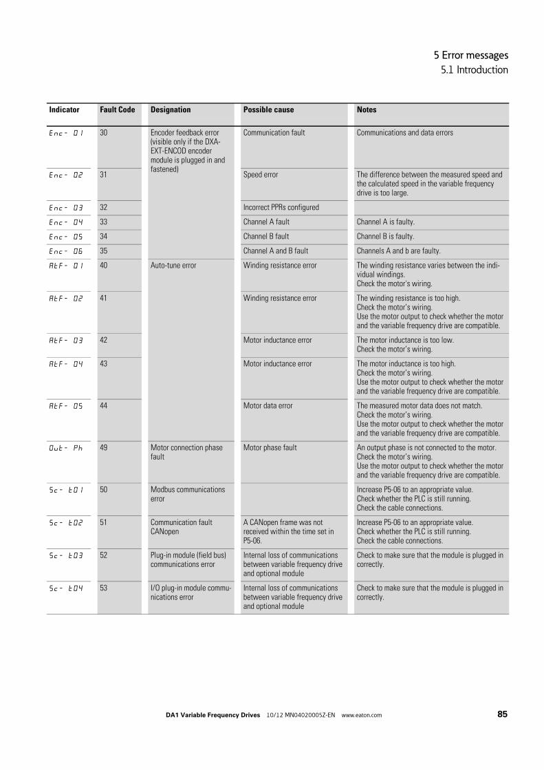
5 Error messages
5.1 Introduction
DA1 Variable Frequency Drives 10/12 MN04020005Z-EN www.eaton.com 85
Enc- 01 30 Encoder feedback error(visible only if the DXA-EXT-ENCOD encoder module is plugged in and fastened)
Communication fault Communications and data errors
Enc- 02 31 Speed error The difference between the measured speed and the calculated speed in the variable frequency drive is too large.
Enc- 03 32 Incorrect PPRs configured
Enc- 04 33 Channel A fault Channel A is faulty.
Enc- 05 34 Channel B fault Channel B is faulty.
Enc- 06 35 Channel A and B fault Channels A and b are faulty.
AtF- 01 40 Auto-tune error Winding resistance error The winding resistance varies between the indi-vidual windings.Check the motor's wiring.
AtF- 02 41 Winding resistance error The winding resistance is too high.Check the motor’s wiring.Use the motor output to check whether the motor and the variable frequency drive are compatible.
AtF- 03 42 Motor inductance error The motor inductance is too low.Check the motor’s wiring.
AtF- 04 43 Motor inductance error The motor inductance is too high.Check the motor’s wiring.Use the motor output to check whether the motor and the variable frequency drive are compatible.
AtF- 05 44 Motor data error The measured motor data does not match.Check the motor’s wiring.Use the motor output to check whether the motor and the variable frequency drive are compatible.
Out- Ph 49 Motor connection phase fault
Motor phase fault An output phase is not connected to the motor.Check the motor’s wiring.Use the motor output to check whether the motor and the variable frequency drive are compatible.
Sc- t01 50 Modbus communications error
Increase P5-06 to an appropriate value.Check whether the PLC is still running.Check the cable connections.
Sc- t02 51 Communication fault CANopen
A CANopen frame was not received within the time set in P5-06.
Increase P5-06 to an appropriate value.Check whether the PLC is still running.Check the cable connections.
Sc- t03 52 Plug-in module (field bus) communications error
Internal loss of communications between variable frequency drive and optional module
Check to make sure that the module is plugged in correctly.
Sc- t04 53 I/O plug-in module commu-nications error
Internal loss of communications between variable frequency drive and optional module
Check to make sure that the module is plugged in correctly.
Indicator Fault Code Designation Possible cause Notes

5 Error messages
5.1 Introduction
86 DA1 Variable Frequency Drives 10/12 MN04020005Z-EN www.eaton.com

6 Parameters
DA1 Variable Frequency Drives 10/12 MN04020005Z-EN www.eaton.com 87
6 Parameters
Table 10: Description list for DA1 parameters
→ When first switching on or after activating the default settings parameter P1-14 must be set to 201 for access to all parame-ters.
PNU ID Access right Value Description DS
RUN ro/rw
Parameter group P1 – quick-start
P1-01 129 rw Maximum frequency / maximum speed 50.0
P1-10 = 0 → P1-02 - 5 x P1-09 → HzP1-10 > 0 → P1-02 - 5 x P1-09 x 60 s → rpmThe maximum output frequency / motor speed limit in Hz or rpm. If P-10 > 0, the value entered / displayed will be shown in rpm.
P1-02 102 rw Minimum frequency / minimum speed 0
P1-10 = 0 → 0 - P1-01 → HzP1-10 > 0 → 0 - P1-01 → rpmThe minimum output frequency / minimum speed limit in Hz or rpm. If P-10 > 0, the value entered / displayed will be shown in rpm.
P1-03 103 rw Acceleration time (acc1) 5 (10 from FS4)
0.1 - 600 s
P1-04 104 rw Deceleration time (dec1) 5 (10 from FS4)
0.1 - 600 s
P1-05 rw Stop Function 1
0 Ramp, deceleration =Regenerative braking. Deceleration time with the value set under P1-04 (dec1).If the energy that is fed back by the motor during the dynamic braking is too high, the deceleration time has to be extended. In devices with an internal braking transistor, the excess energy can be dissipated with an external braking resistance (optional)
1 Free coasting =After the start enable (FWD/REV) is switched off or the STOP pushbutton is pressed (P1-12 and P1-13), the motor will coast uncontrolled.
2 Ramp, quick stop = regenerative braking.Deceleration time 2 with the value set under P2-25 (dec2).If the energy that is fed back by the motor during the dynamic braking is too high, the deceleration time has to be extended. In devices with an internal braking transistor, the excess energy can be dissipated with an external braking resistor (optional).

6 Parameters
88 DA1 Variable Frequency Drives 10/12 MN04020005Z-EN www.eaton.com
3 Free coasting, with activated braking chopper =After the start enable (FWD/REV) is switched off or the STOP pushbutton is pressed (P1-12 and P1-13), the motor will coast uncontrolled.If the energy that is fed back by the motor during the dynamic braking is too high, the deceleration time has to be extended. In devices with an internal braking transistor, the excess energy can be dissipated with an external braking resistor (optional).
P1-06 106 rw Energy optimization 0
0 Deactivated
1 ActivatedIf it is selected, the energy optimization function will attempt to reduce the total energy consumed by the variable frequency drive and the motor during operation at constant speeds and with light loads. The output voltage applied at the motor will be reduced. The energy optimization function is intended for appli-cations in which the variable frequency drive is run for specific periods at a constant speed and with a light load, indepen-dently of whether the torque is constant or varies.
P1-07 107 – rw Nominal voltage of the motor 2301)
Setting range: 0. 20 - 250 / 500 V (→ Motor ratings plate)Pay attention to the supply voltage and the type of circuit in the stator winding!
Note:This parameter value has a direct influence on the V/f charac-teristic curve (e.g. operation with 87 Hz characteristic curve). This must be especially taken into account in the case of values (P1-07) that deviate from the variable frequency drive’s rated operational data (ULN = 100 %). This may cause the over-exci-tation of the motor and thus lead to an increased thermal load.
P1-08 108 – rw Rated motor current 4.81)
Setting range: 0.2 x Ie - Ie [A] (→ Motor rating plate)Ie = Variable frequency drive’s rated operational current
P1-09 109 – rw Nominal frequency of the motor 50.01)
Setting range: 25 - 500 Hz (→ Motor rating plate)
Note:This parameter value is also automatically applied as the cut-off frequency for the V/Hz characteristic curve.
PNU ID Access right Value Description DS
RUN ro/rw

6 Parameters
DA1 Variable Frequency Drives 10/12 MN04020005Z-EN www.eaton.com 89
P1-10 110 rw Nominal speed of the motor 0
0 - 30000 rpm (→ motor rating plate)
Note:This parameter can be optionally set to the motor’s rated speed (revolutions per minute, rating plate). If it is set to the factory default setting of 0, all speed-related parameters will be shown in Hz; slip compensation for the motor will be disabled. Entering the value on the motor's rating plate will enable the slip compensation function, and the variable frequency drive's display will show the motor speed in the estimated rpm.All speed-related parameters (such as the minimum and maximum frequencies and the fixed frequencies) will also be shown in rpm.
P1-11 111 – rw Output voltage at zero frequency 3.0
0.00 - 20.0 %
Voltage amplification is used in order to increase the motor voltage applied at low output frequencies so as to improve the torque at low speeds, as well as the starting torque.
Note:A high start voltage enables a high torque at the start.
Notice:A high torque at low speed causes a high thermal load on the motor. If temperatures are too high, the motor should be equipped with an external fan.
P1-12 140 – rw Control level 0
0 Control signal terminals (I/O)The variable frequency drive will respond directly to signals applied to the control signal terminals.
1 Keypad (KEYPAD FWD)The variable frequency drive can only be controlled in the forward direction if an external or remote control keypad is used.
2 Keypad (KEYPAD FWD/REV)The variable frequency drive can be controlled in both the forward and reverse directions by using an external or remote control keypad. Pressing the START pushbutton will toggle between the forward and reverse directions.
3 PID controllerThe output frequency will be controlled by the internal PID controller.
4 Field busControl via Modbus RTU (RS485) interface or optional fieldbus connection (e.g., PROFIBUS DP).
5 Slave modeThe variable frequency drive will run in slave mode; in this mode, the output frequency will depend on the master variable frequency drive and can only be changed there. The variable frequency drives are connected to each other using the variable frequency drive's RJ45 interface.
6 Field bus (CANopen) via RJ45 interface
PNU ID Access right Value Description DS
RUN ro/rw

6 Parameters
90 DA1 Variable Frequency Drives 10/12 MN04020005Z-EN www.eaton.com
P1-13 113 – ro Digital input (analog input) function
P1-14 114 rw Parameter range access code 0
(Depends on P2-40 or P6-30 Extended parameter access code)
Set the value to 101 (default setting) to enable access to the extended parameter menu. Modify via P2-40.To enable access to all parameters, set the value to 201. Change using P6-30.
Extended parameter range Level 2 (access: P1-14 = 101 or P1-14 = 201)Parameter group P2 - functions
P2-01 201 rw Fixed frequency FF1 / speed 1 5.0
P1-10 = 0 → -P1-02 - P1-01 → HzP1-10 > 0 → -P1-02 - P1-01 x 60 s → rpm (1/min)
0.00 Hz (P1-02) up to the maximum frequency value (P1-01).Activation via digital inputs depending on parameters P1-12 and P1-13 according to the "Input value DA1" table.
P2-02 202 rw Fixed frequency FF2 / speed 2 10.0
P1-10 = 0 → -P1-02 - P1-01 → HzP1-10 > 0 → -P1-02 - P1-01 x 60 s → rpm (1/min)
0.00 Hz (P1-02) up to the maximum frequency value (P1-01).Activation via digital inputs depending on parameters P1-12 and P1-13.
P2-03 203 rw Fixed frequency FF3 / speed 3 25.0
P1-10 = 0 → -P1-02 - P1-01 → HzP1-10 > 0 → -P1-02 - P1-01 x 60 s → rpm (1/min)
0.00 Hz (P1-02) up to the maximum frequency value (P1-01).Activation via digital inputs depending on parameters P1-12 and P1-13.
P2-04 204 rw Fixed frequency FF4 / speed 4 50.0
P1-10 = 0 → -P1-02 - P1-01 → HzP1-10 > 0 → -P1-02 - P1-01 x 60 s → rpm (1/min)
0.00 Hz (P1-02) up to the maximum frequency value (P1-01).Activation via digital inputs depending on parameters P1-12 and P1-13.
P2-05 201 rw Fixed frequency FF5 / speed 5 0.0
P1-10 = 0 → -P1-02 - P1-01 → HzP1-10 > 0 → -P1-02 - P1-01 x 60 s → rpm (1/min)
0.00 Hz (P1-02) up to the maximum frequency value (P1-01).Activation via digital inputs depending on parameters P1-12 and P1-13.
P2-06 206 rw Fixed frequency FF6 / speed 6 0.0
P1-10 = 0 → -P1-02 - P1-01 → HzP1-10 > 0 → -P1-02 - P1-01 x 60 s → rpm (1/min)
0.00 Hz (P1-02) up to the maximum frequency value (P1-01).Activation via digital inputs depending on parameters P1-12 and P1-13.
PNU ID Access right Value Description DS
RUN ro/rw

6 Parameters
DA1 Variable Frequency Drives 10/12 MN04020005Z-EN www.eaton.com 91
P2-07 207 rw Fixed frequency FF7 / speed 7 0.0
P1-10 = 0 → -P1-02 - P1-01 → HzP1-10 > 0 → -P1-02 - P1-01 x 60 s → rpm (1/min)
0.00 Hz (P1-02) up to the maximum frequency value (P1-01).Activation via digital inputs depending on parameters P1-12 and P1-13.
P2-08 208 rw Fixed frequency FF8 / speed 8 0.0
P1-10 = 0 → -P1-02 - P1-01 → HzP1-10 > 0 → -P1-02 - P1-01 x 60 s → rpm (1/min)
0.00 Hz (P1-02) up to the maximum frequency value (P1-01).Activation via digital inputs depending on parameters P1-12 and P1-13.
P2-09 209 rw Frequency skip 1, bandwidth (hysteresis range) 0
0.00 - P1-01 (fmax)
P2-10 210 rw Frequency skip 1, center 0
P1-02 (fmin) - P1-01 (fmax)
The skip frequency function is used to prevent the variable frequency drive from being run at a specific output frequency, e.g. at a frequency that will cause mechanical resonance in a specific machine.Parameter P2-10 is used to define the center of the skip frequency band and is used together with parameter P2-09. The output frequency will run through the specified band at the speeds set in P1-03 or P1-04 without holding an output frequency that falls within the defined band. If the frequency reference value applied to the variable frequency drive falls within the band, the output frequency will remain at the upper or lower limit of the band.
PNU ID Access right Value Description DS
RUN ro/rw

6 Parameters
92 DA1 Variable Frequency Drives 10/12 MN04020005Z-EN www.eaton.com
P2-11 211 rw AO1 signal 8
Digital output → +24 V DC
0 RUN, enable (FWD, REV)
1 READY, ready for operation
2 Output frequency = frequency reference value
3 Output frequency > zero speed
4 Output frequency closing threshold > P2-16Switch off threshold < P2-17
5 Output current closing threshold > P2-16Switch off threshold < P2-17
6 Output torque closing threshold > P2-16Switch off threshold < P2-17
7 AI2 signal level closing threshold > P2-16Switch off threshold < P2-17
Analog output → P2-12
8 Output frequency f-Out → 0 - 100 % fmax (P1-01)
9 Output current → 0 - 200 % Ie (P1-08)
10 Torque MN → 0 - 200 % (calculated value)
11 Output power PN → 0 - 150 % (Ie)
P2-12 212 rw AO1, signal range A0-10
A0-10 0 - 10 V
A10-0 10 - 0 V
A0-20 0 - 20 mA
A20-0 20 - 0 mA
A4-20 4 - 20 mA
A20-4 20 - 4 mA
PNU ID Access right Value Description DS
RUN ro/rw

6 Parameters
DA1 Variable Frequency Drives 10/12 MN04020005Z-EN www.eaton.com 93
P2-13 213 rw AO1 signal 9
Digital output → +24 V DC
0 RUN, enable (FWD, REV)
1 READY, ready for operation
2 Output frequency = frequency reference value
3 Output frequency > zero speed
4 Output frequency closing threshold > P2-19Switch off threshold < P2-20
5 Output current closing threshold > P2-19Switch off threshold < P2-20
6 Output torque closing threshold > P2-19Switch off threshold < P2-20
7 AI2 signal level closing threshold > P2-19Switch off threshold < P2-20
Analog output → 0 - 10 V DC
8 Output frequency f-Out → 0 - 100 % fmax (P1-01)
9 Output current → 0 - 200 % Ie (P1-08)
10 Torque MN → 0 - 200 % (calculated value)
11 Output power PN → 0 - 150 % (Ie)
P2-14 214 rw AO1, signal range A0-10
A0-10 0 - 10 V
A10-0 10 - 0 V
A0-20 0 - 20 mA
A20-0 20 - 0 mA
A4-20 4 - 20 mA
A20-4 20 - 4 mA
PNU ID Access right Value Description DS
RUN ro/rw

6 Parameters
94 DA1 Variable Frequency Drives 10/12 MN04020005Z-EN www.eaton.com
P2-15 215 rw K1 signal (Relay Output 1) 1
Used to select the function assigned to the relay output. The relay has three output terminals (changeover contacts): Logic 1 indicates that the relay is active: This is why terminals 14 and 15 are connected to each other.
0 RUN, enable (FWD, REV)
1 READY, ready for operation
2 Output frequency = frequency reference value
3 Output frequency > 0 Hz
4 Output FrequencyClosing threshold > P2-16Switch off threshold < P2-17
5 Output currentClosing threshold > P2-16Switch off threshold < P2-17
6 Output torque (calculated value)Closing threshold > P2-16Switch off threshold < P2-17
7 Analog Input (AI2)Closing threshold > P2-16Switch off threshold < P2-17
P2-16 216 rw AO1 / K1 upper limit 100.0
The adjustable upper limit value that is being used in connec-tion with settings 4 to 7 of P2-11 and P2-15
0.0 - 200.0 %
P2-17 217 rw AO1 / K1 lower limit 0.0
The adjustable lower limit value that is being used in connec-tion with settings 4 to 7 of P2-11 and P2-15
0.0 - 200.0 %
PNU ID Access right Value Description DS
RUN ro/rw

6 Parameters
DA1 Variable Frequency Drives 10/12 MN04020005Z-EN www.eaton.com 95
P2-18 218 rw K2 signal (Relay Output 1) 0
Used to select the function assigned to the relay output. The relay has two output terminals: Logic 1 indicates that the relay is active: This is why terminals 17 and 18 are connected to each other.
0 RUN, enable (FWD, REV)
1 READY, variable frequency drive ready for operation
2 Output frequency = frequency reference value
3 Output frequency > 0 Hz
4 Output FrequencyClosing threshold > P2-16Switch off threshold < P2-17
5 Output currentClosing threshold > P2-16Switch off threshold < P2-17
6 Output torque (calculated value)Closing threshold > P2-16Switch off threshold < P2-17
7 Analog input (AI) 2Closing threshold > P2-16Switch off threshold < P2-17
8 PLC for external (hub) brake.This setting also enables the special operating mode for hoisting gear. Please contact your sales office for details.
P2-19 219 rw AO2/K2 upper limit 100.0
The adjustable upper limit value that is being used in connec-tion with settings 4 to 7 of P2-13 and P2-18
0.0 - 200.0 %
P2-20 220 rw AO2/K2 lower limit 0.0
The adjustable lower limit value that is being used in connec-tion with settings 4 to 7 of P2-13 and P2-18
0.0 - 200.0 %
P2-21 221 rw Scaling factor for value 0.00
The variable selected with P2-22 is scaled with the factor selected in P2-21.
-30.00 - 30.00
P2-22 222 rw scaled display value 0
Used to select the variable that should be scaled with the factor specified in P2-21.
0 Output Frequency
1 Output current
2 Analog input 2
3 P0-80 value
PNU ID Access right Value Description DS
RUN ro/rw

6 Parameters
96 DA1 Variable Frequency Drives 10/12 MN04020005Z-EN www.eaton.com
P2-23 223 rw Holding time for speed of 0 0.2
Used to define the time that the variable frequency drive will continue to output 0 Hz (after reaching 0 Hz) before stopping.
0.0 - 60.0 s
P2-24 224 – Clock frequency FS2: 16 kHzFS3, FS4,FS5: 8 kHzFS6, FS7: 4 kHz
4 - 32 kHz
RMS switching frequency of power stage.A higher frequency will reduce motor noise and improve the output current's waveform, while causing increased heat loss in the variable frequency drive.
P2-25 225 rw Quick stop deceleration ramp time/deceleration time (dec 2) 0.0
Ramp time for quick deceleration ramp
Note:In the event of a power failure, it is selected automatically or via a digital input (DI) if P2-38 = 2.If the parameter is set to 0.0, the motor will coast until it stops.
0.0 - 240.0 s
P2-26 226 rw Flying restart circuit 0
If this parameter is enabled, the variable frequency drive will attempt, upon starting, to determine whether the motor is already turning and to reduce its current speed in a controlled manner. A brief deceleration will occur if motors that are not already turning are started.
0 Deactivated
1 Enabled
P2-27 227 rw Delay time in Standby mode 0.0
Activates the Standby mode
0.0 Standby mode deactivated
> 0 - 250 s The drive will switch to standby mode (the output will be deac-tivated) if the minimum speed (P1-02) is maintained for the time specified in this parameter. Operation will resume automati-cally as soon as the setpoint frequency increases to a frequency higher than P1-02.
PNU ID Access right Value Description DS
RUN ro/rw

6 Parameters
DA1 Variable Frequency Drives 10/12 MN04020005Z-EN www.eaton.com 97
P2-28 228 rw Slave speed scaling 0
This parameter is only enabled in keypad mode (P1-12 = 1 or 2) and slave mode (P1-12 = 5). The setpoint value can be scaled with a factor (P2-29), with the factor and by additionally adding the analog input (P2-29 + AI1), or with the factor and an addi-tional factor (P2-29 x AI1).
0 Deactivated
1 Process speed → Digital speed x P2-29
2 Process speed → (Digital speed x P2-29) + AI1
3 Process speed → (Digital speed x P2-29) x AI1
P2-29 229 rw Slave speed scaling factor 100.0
Factor for P2-28
-500 - 500 %
P2-30 230 rw AI1, Signal range A0-10
A0-10 0 to 10 V signal (unipolar)The variable frequency drive will remain at 0.0 Hz if the analog signal is < 0.0 % after scaling and applying the corresponding offset.
A10-0 0 to 10 V signal (unipolar).The variable frequency drive will remain at 0.0 Hz if the analog signal is < 0.0 % after scaling and applying the corresponding offset.
- 10- 10 -10 to 10 V signal (bipolar).The variable frequency drive will drive the motor in the reverse operating direction as soon as the analog reference value is less than 0.0 % after scaling and applying the corresponding offset.
A0-20 0 to 20 mA (unipolar)The variable frequency drive will remain at 0.0 Hz if the analog signal is < 0.0 % after scaling and applying the corresponding offset.
t4-20 4 to 20 mA signalThe variable frequency drive will be switched off and show failure code 4-20F as soon as the signal level falls below 3 mA.
r4-20 4 to 20 mA signalThe variable frequency drive will run as per a ramp all the way to a stop as soon as the signal level falls below 3 mA.
t20-4 20 to 4 mA signalThe variable frequency drive will be switched off and show failure code 4-20F as soon as the signal level falls below 3 mA.
r20-4 20 to 4 mA signalThe variable frequency drive will run as per a ramp all the way to a stop as soon as the signal level falls below 3 mA.
PNU ID Access right Value Description DS
RUN ro/rw

6 Parameters
98 DA1 Variable Frequency Drives 10/12 MN04020005Z-EN www.eaton.com
P2-31 231 rw AI1 scaling factor 100.0
0 - 500 %
Scales the analog input by this factor; e.g., if P2-30 is config-ured for a 0 - 10 V signal and the scaling factor is set to 200.0 %, 5 V at the input will cause the variable frequency drive to run at the maximum frequency / speed (P-01).
P2-32 232 rw Analog input 1 Offset 0.0
-500.0 - +500.0 %
Used to set an offset as a percentage of the input's full scale range so that this offset will be applied to the analog input signal.
P2-33 233 rw AI2, Signal range V0-10
V0-10 0-10 V signal (unipolar).The variable frequency drive will remain at 0.0 Hz if the analog signal is < 0.0 % after scaling and applying the corresponding offset.
V10-0 10-0 V signal (unipolar).The variable frequency drive will remain at 0.0 Hz if the analog signal is < 0.0 % after scaling and applying the corresponding offset.
Ptc-th Motor thermistor input
A0-20 0 to 20 mA (unipolar)The variable frequency drive will remain at 0.0 Hz if the analog signal is < 0.0 % after scaling and applying the corresponding offset.
t4-20 4-20 mA signalThe variable frequency drive will be switched off and show failure code 4-20F as soon as the signal level falls below 3 mA.
r4-20 4-20 mA signalThe variable frequency drive will run as per a ramp all the way to a stop as soon as the signal level falls below 3 mA.
t20-4 20-4 mA signalThe variable frequency drive will be switched off and show failure code 4-20F as soon as the signal level falls below 3 mA.
r20-4 20-4 mA signalThe variable frequency drive will run as per a ramp all the way to a stop as soon as the signal level falls below 3 mA.
P2-34 234 rw AI2 scaling factor 100.0
0 - 500 %
Used to scale the analog input by this factor.For example, if P2-33 is configured for a 0 - 10 V signal and the scaling factor is set to 200.0 %, 5 V at the input will cause the variable frequency drive to run at the maximum frequency / speed (P-01).
PNU ID Access right Value Description DS
RUN ro/rw

6 Parameters
DA1 Variable Frequency Drives 10/12 MN04020005Z-EN www.eaton.com 99
P2-35 235 rw AI2 offset 0.0
-500.0 - +500.0 %
Used to set an offset as a percentage of the input's full scale range so that this offset will be applied to the analog input signal.
P2-36 236 rw REAF, Start function with automatic restart Ed9E-r
Used to define the variable frequency drive's behavior concerning the enable digital input and to configure the auto-matic restart function.
Ed9E-r disabled
(the variable frequency drive will need a new start edge) :After being switched on, as well as after a reset, the variable frequency drive will not start if digital input 1 remains closed. The input must be closed after switching on, as well as after a reset, in order to start the variable frequency drive.
AVto-0 The variable frequency drive will start automatically (The vari-able frequency drive does not need a start edge; the signal will continue to be applied).
After being switched on, as well as after a reset, the variable frequency drive will start automatically if digital input 1 is closed.
AVto-1 The variable frequency drive will start automatically once.
After a trip, the variable frequency drive will make up to five attempts to restart at 20-second intervals. The variable frequency drive must be de-energized in order to reset the counter. The number of restart attempts is counted. If the variable frequency drive does not start after the last attempt, it will switch to an error condition and request the user to reset the error manually.
AVto-2 The variable frequency drive will start automatically twice.
AVto-3 The variable frequency drive will start automatically three times.
AVto-4 The variable frequency drive will start automatically four times.
AVto-5 The variable frequency drive will start automatically five times.
PNU ID Access right Value Description DS
RUN ro/rw

6 Parameters
100 DA1 Variable Frequency Drives 10/12 MN04020005Z-EN www.eaton.com
P2-37 237 rw REAF, Start function with automatic restart, operating unit 1
This parameter will only be active if the keypad control oper-ating mode is being used (P-12 = 1 or 2).
0 Minimum speed; keypad
The keypad's start and stop pushbuttons are enabled, and control signal terminals 1 and 2 must be connected.The variable frequency drive will always start with the minimum frequency/speed (P1-02).
1 Previous speed, keypad
The keypad's start and stop pushbuttons are enabled; control signal terminals 1 and 2 must be connected.The variable frequency drive will always start with the most recent operating frequency/speed.
2 Current speed
The variable frequency drive will start with the most recent current speed without a new start signal.
3 Fixed frequency 8
After a stop, the variable frequency drive will start with fixed frequency 8 (P2-08) without a new start command.
4 Minimum frequency (P1-02)
After a stop, the variable frequency drive will start with the minimum frequency (P1-02) without a new start signal (terminal enable).
5 Most recently set speed
After a stop, the variable frequency drive will start with the most recent current frequency (keypad setpoint value) without a new start signal (terminal enable).
6 Current speed
If the variable frequency drive is configured for multiple speed reference values (typically manual/auto control or local/remote control) and a digital input is setting it to setpoint value = keypad, the motor will continue to be run with the most recent setpoint value (terminal enable)
7 Fixed frequency 8
After a stop, the variable frequency drive will start with fixed frequency 8 (P2-08) without a new start command (terminal enable).
PNU ID Access right Value Description DS
RUN ro/rw

6 Parameters
DA1 Variable Frequency Drives 10/12 MN04020005Z-EN www.eaton.com 101
P2-38 238 rw Response in the event of a power failure 0
Used to control the variable frequency drive's behavior after a power supply loss while the drive is switched on.
0 Voltage support in the event of a power failure
The variable frequency drive will reduce the output frequency as specified in the ramp (dec1). The regenerative energy recov-ered from the motor's load will continue to power the variable frequency drive, provided the power failure is brief and enough energy can be recovered from the machine in order to power the controller.
1 Stop, free coasting
The variable frequency drive will immediately deactivate the output so that the motor will coast. If this setting is used for loads with a large moment of inertia, the flying restart circuit (P2-26) should be enabled in order to make it possible to restart quickly.
2 Quick stop (P2-25)
The variable frequency drive will stop with the quick stop ramp time (dec2) set in parameter P2-25.
3 Only DC power supply present
This mode should be used if the variable frequency drive is being powered directly with the +DC- and -DC bus connections. Undervoltage detection is disabled in this mode.
P2-39 239 rw Parameter access lock 0
0 Deactivated
Access to all parametersChanges are allowed (some of them are not allowed in RUN mode, however).
1 Activated
Parameter values can be shown, but cannot be edited.
P2-40 240 rw Access codes - menu level 2 101
0 - 9999
Used to define the access code that must be entered into P1-14 to allow access to parameter groups 1 to 5.
PNU ID Access right Value Description DS
RUN ro/rw

6 Parameters
102 DA1 Variable Frequency Drives 10/12 MN04020005Z-EN www.eaton.com
Parameter group P3 – PID controller
P3-01 301 rw PID controller proportional gain 1.0
0.1 - 30.0 %
Higher values will result in a larger change to the variable frequency drive output frequency as a response to small changes in the feedback signal. An excessively high value can cause instability.
P3-02 302 rw PID controller, integral time constant 1.0
0.00 - 30.0 s
Higher values will result in a more damped response for systems in which the overall process responds slowly.
P3-03 303 rw PID controller, D rate time 0.00
0.00 - 1.00 s
PID controller, Differential Time Constant
P3-04 304 rw PID controller, control deviation 0
0 direct operation
Note:This mode should be used if a decrease in the feedback signal's level should result in a higher motor speed.
1 Inverse operation
Note:This mode should be used if an increase in the feedback signal's level should result in a higher motor speed.
P3-05 305 rw PID controller, setpoint source 0
0 Preset digital setpoint value (P3-6)
1 AI1
2 AI2
P3-06 306 rw PID controller, digital reference value 0.0
0.00 - 100 %
Is used at P3-05 = 0
P3-07 307 rw PID controller, actual value limiting, maximum 100.0
0.0 - 100.0 %
Is used at P3-09 = 0
P3-08 308 rw PID controller, actual value limiting, minimum 0.0
0.0 - 100.0 %
Is used at P3-09 = 0
PNU ID Access right Value Description DS
RUN ro/rw

6 Parameters
DA1 Variable Frequency Drives 10/12 MN04020005Z-EN www.eaton.com 103
P3-09 309 rw PID controller, actual value limitingSelections
0
0 Actual value limiting (P3-08 - P3-07)
1 AI1 = Actual value limiting, maximum
2 AI1 = Actual value limiting, minimum
3 PID controller output + AI1
P3-10 310 rw PID controller, actual value (PV) feedback signal 0
0 0 = AI1
1 1 = AI2
P3-11 311 rw Maximum PID error for enabling the ramps 0.0
0.00 - 25.0 %
Used to define a PID error threshold value. If the PID error (the difference between the setpoint and the process variable) is smaller than the threshold value, the variable frequency drive’s internal ramps will be deactivated.
P3-12 312 rw PID feedback display scaling factor 0.00
0 - 50 %
Applies a scaling factor to the displayed PID feedback, allowing the user to display the actual signal level from a transducer.
P3-13 313 rw PID feedback wake up level 0.0
0.0 - 100.0 %
Sets an error level (difference between the PID reference and feedback values) above which the PID controller will wake from Standby mode.
P3-14 – – – – reserved –
P3-15 – – – – reserved –
P3-16 – – – – reserved –
P3-17 – – – – reserved –
P3-18 318 rw PID reset control 0
This parameter controls the PID loop's resetting behavior.
0 The PID loop will run continuously as long as the proportional gain (P3-01) is not 0.
1 The PID loop will only run if the drive is active. If the drive is not running, the PID output will be reset to 0 (incl. integer result).
PNU ID Access right Value Description DS
RUN ro/rw
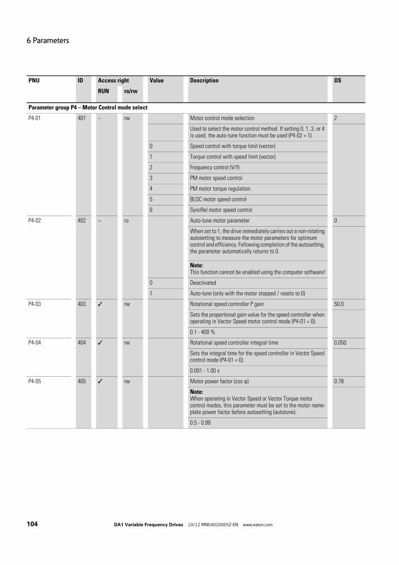
6 Parameters
104 DA1 Variable Frequency Drives 10/12 MN04020005Z-EN www.eaton.com
Parameter group P4 – Motor Control mode select
P4-01 401 – rw Motor control mode selection 2
Used to select the motor control method. If setting 0, 1, 3, or 4 is used, the auto-tune function must be used (P4-02 = 1).
0 Speed control with torque limit (vector)
1 Torque control with speed limit (vector)
2 Frequency control (V/f)
3 PM motor speed control
4 PM motor torque regulation
5 BLDC motor speed control
6 SyncRel motor speed control
P4-02 402 – ro Auto-tune motor parameter 0
When set to 1, the drive immediately carries out a non-rotating autosetting to measure the motor parameters for optimum control and efficiency. Following completion of the autosetting, the parameter automatically returns to 0.
Note:This function cannot be enabled using the computer software!
0 Deactivated
1 Auto-tune (only with the motor stopped / resets to 0)
P4-03 403 rw Rotational speed controller P gain 50.0
Sets the proportional gain value for the speed controller when operating in Vector Speed motor control mode (P4-01 = 0).
0.1 - 400 %
P4-04 404 rw Rotational speed controller integral time 0.050
Sets the integral time for the speed controller in Vector Speed control mode (P4-01 = 0).
0.001 - 1.00 s
P4-05 405 rw Motor power factor (cos ϕ) 0.78
Note:When operating in Vector Speed or Vector Torque motor control modes, this parameter must be set to the motor name-plate power factor before autosetting (autotune).
0.5 - 0.99
PNU ID Access right Value Description DS
RUN ro/rw

6 Parameters
DA1 Variable Frequency Drives 10/12 MN04020005Z-EN www.eaton.com 105
P4-06 406 rw Torque setpoint/limit 0
If P4-01 = 0, this parameter defines the source for the output torque's maximum value.If P4-01 = 1, this parameter defines the source for the torque frequency (setting point)
0 Fixed digital torque limitThe limit value is set in P04-07.
1 Analog input 1 (AI1) will control the torque from 0 to P04-07.
2 Analog input 2 (AI2) will control the torque from 0 to P4-07.
3 Field bus. The field bus torque setpoint is used, limited by P4-07.
4 Master/Slave. The master's torque reference value will be used as the torque limit for the slave.
5 PID controller output. The PID controller will be used to control the torque from 0 to P4-07.
P4-07 407 rw Maximum torque (motor) 200
When operating in Vector Speed or Vector Torque motor control modes (P4-01 = 2), this parameter defines the maximum torque limit or reference used by the drive in conjunction with P4-06 parameters.
P4-08 - 500 %
P4-08 408 rw Minimum torque 0
Active only in Vector Speed or Vector Torque motor control modes (P4-01 = 2).Used to define a minimum torque so that, if the drive is active, the system will always attempt to ensure this torque on the motor.
Note:This parameter should be used with care, as the drive output frequency will increase to achieve the set torque level, and may exceed the setpoint frequency.
0.00 - P4-07 %
P4-09 409 rw Maximum torque (generator) 200
Active only in Vector Speed or Vector Torque motor control modes (P4-01 = 2). Sets the maximum regenerating torque allowed by the drive.
0.00 - 200 %
P4-10 410 – rw V/Hz characteristic curve modification voltage 0.0
When operating in V/f mode (P4-01 = 2), this parameter in conjunction with P4-11 sets a frequency point at which the voltage set in P4-11 is applied to the motor.
Note:Care must be taken to avoid overheating and damaging the motor when using this function.
0.00 - P1-09 %
PNU ID Access right Value Description DS
RUN ro/rw

6 Parameters
106 DA1 Variable Frequency Drives 10/12 MN04020005Z-EN www.eaton.com
P4-11 411 rw V/Hz characteristic curve modification frequency 0.0
Used in conjunction with P4-10.
0.00 - P1-07 %
P4-12 412 – – – reserved
Parameter group P5 – Field bus
P5-01 501 rw Variable frequency drive slave address 1
Used to set the drive network address when using the field bus or master/slave function. Even if multiple variable frequency drives are connected with drivesConnect.
0 - 63
P5-02 502 rw CANopen baudrate 2
Sets the baud rate when CANopen communications are used.
0 125 kbit/s
1 250 kbit/s
2 500 kbit/s
3 1000 kbit/s
P5-03 503 rw Modbus RTU Baud rate 4
Sets the baud rate when Modbus communications are used.
0 9.6 kbit/s
1 19.2 kbit/s
2 38.4 kbit/s
3 57.6 kBit/s
4 115.2 kbit/s
P5-04 504 rw Modbus RTU data format – Parity type n-1
n-1 No parity, 1 stop bit
n-2 No parity, 2 stop bits
0-1 Odd parity, 1 stop bit
E-1 Even parity, 1 stop bit
P5-05 505 rw Timeout – Communications dropout 1
Sets the watchdog time period for the communications channel.With an active communication link, if a valid telegram is not received by the drive within this time period, the drive will assume a loss of communications has occurred and react as set in P5-06.
0.00 - 5.00 s
PNU ID Access right Value Description DS
RUN ro/rw

6 Parameters
DA1 Variable Frequency Drives 10/12 MN04020005Z-EN www.eaton.com 107
P5-06 506 rw Response in the event of a communications dropout 0
Used to control the drive's behavior in the event of a loss of communications.
0 = Switch off and free coasting
1 = Deceleration ramp, switch off
2 = Deceleration ramp, no switch off
3 = Fixed frequency 8
P5-07 507 rw Ramp via field bus 0
Used to define whether the acceleration and deceleration ramps will be controlled directly through the field bus or through internal drive parameters.
0 DeactivatedRamps will be controlled using internal drive parameters.
1 ActivatedRamps will be controlled directly through the field bus.
P5-08 508 rw Field bus module PDO-4 output 0
When using an optional field bus interface, this parameter configures the parameter source for the 4th process data word transferred from the network master to the drive during cyclic communications.
0 Output torque, as a percentage, with one decimal place(Example: 123 = 12.3 %)
1 Output power, in kW, with two decimal places(Example: 400 = 4.00 kW)
2 Digital input (DI) states → Bit 0 gives the state of digital input 1 (DI1), bit 1 the state of digital input 2 (DI2), etc.
3 Signal level analog input 2 (AI2) → 0 - 1000 = 0 - 100.0 %
4 Heat sink temperature → 0 - 100 = 0 - 100 °C
5 User register 1 → Can be accessed with the PLC program (inter-nally) or parameter group 9.
6 User register 2 → Can be accessed with the PLC program (inter-nally) or parameter group 9.
7 Value P0-80 can be selected via P6-28.
P5-09 - – - – reserved
P5-10 - – - – reserved
P5-11 - – - – reserved
PNU ID Access right Value Description DS
RUN ro/rw
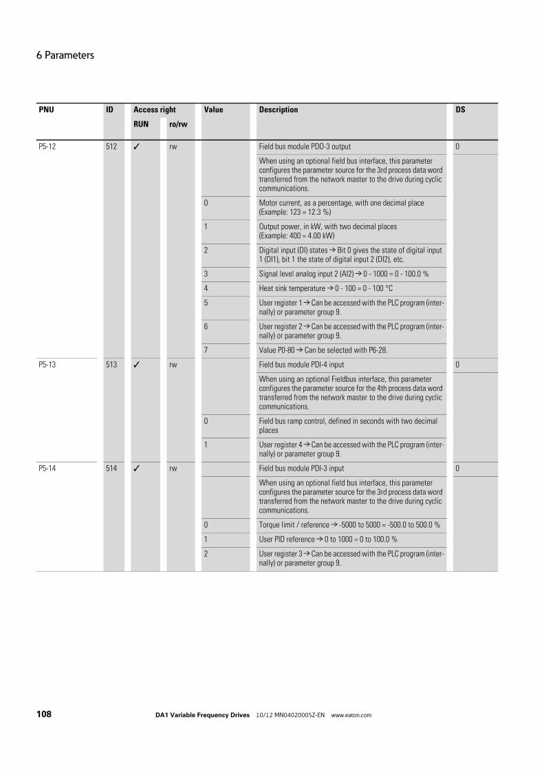
6 Parameters
108 DA1 Variable Frequency Drives 10/12 MN04020005Z-EN www.eaton.com
P5-12 512 rw Field bus module PDO-3 output 0
When using an optional field bus interface, this parameter configures the parameter source for the 3rd process data word transferred from the network master to the drive during cyclic communications.
0 Motor current, as a percentage, with one decimal place(Example: 123 = 12.3 %)
1 Output power, in kW, with two decimal places(Example: 400 = 4.00 kW)
2 Digital input (DI) states → Bit 0 gives the state of digital input 1 (DI1), bit 1 the state of digital input 2 (DI2), etc.
3 Signal level analog input 2 (AI2) → 0 - 1000 = 0 - 100.0 %
4 Heat sink temperature → 0 - 100 = 0 - 100 °C
5 User register 1 → Can be accessed with the PLC program (inter-nally) or parameter group 9.
6 User register 2 → Can be accessed with the PLC program (inter-nally) or parameter group 9.
7 Value P0-80 → Can be selected with P6-28.
P5-13 513 rw Field bus module PDI-4 input 0
When using an optional Fieldbus interface, this parameter configures the parameter source for the 4th process data word transferred from the network master to the drive during cyclic communications.
0 Field bus ramp control, defined in seconds with two decimal places
1 User register 4 → Can be accessed with the PLC program (inter-nally) or parameter group 9.
P5-14 514 rw Field bus module PDI-3 input 0
When using an optional field bus interface, this parameter configures the parameter source for the 3rd process data word transferred from the network master to the drive during cyclic communications.
0 Torque limit / reference → -5000 to 5000 = -500.0 to 500.0 %
1 User PID reference → 0 to 1000 = 0 to 100.0 %
2 User register 3 → Can be accessed with the PLC program (inter-nally) or parameter group 9.
PNU ID Access right Value Description DS
RUN ro/rw
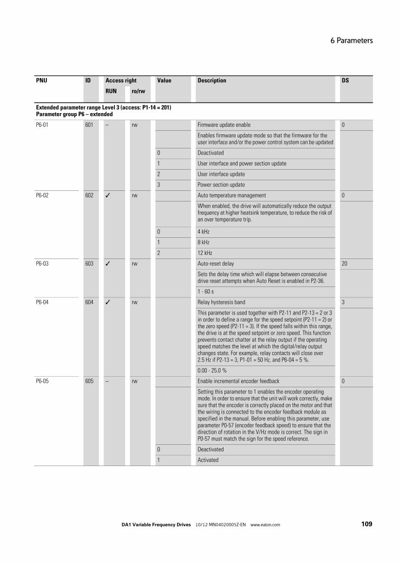
6 Parameters
DA1 Variable Frequency Drives 10/12 MN04020005Z-EN www.eaton.com 109
Extended parameter range Level 3 (access: P1-14 = 201)Parameter group P6 – extended
P6-01 601 – rw Firmware update enable 0
Enables firmware update mode so that the firmware for the user interface and/or the power control system can be updated
0 Deactivated
1 User interface and power section update
2 User interface update
3 Power section update
P6-02 602 rw Auto temperature management 0
When enabled, the drive will automatically reduce the output frequency at higher heatsink temperature, to reduce the risk of an over temperature trip.
0 4 kHz
1 8 kHz
2 12 kHz
P6-03 603 rw Auto-reset delay 20
Sets the delay time which will elapse between consecutive drive reset attempts when Auto Reset is enabled in P2-36.
1 - 60 s
P6-04 604 rw Relay hysteresis band 3
This parameter is used together with P2-11 and P2-13 = 2 or 3 in order to define a range for the speed setpoint (P2-11 = 2) or the zero speed (P2-11 = 3). If the speed falls within this range, the drive is at the speed setpoint or zero speed. This function prevents contact chatter at the relay output if the operating speed matches the level at which the digital/relay output changes state. For example, relay contacts will close over 2.5 Hz if P2-13 = 3, P1-01 = 50 Hz, and P6-04 = 5 %.
0.00 - 25.0 %
P6-05 605 – rw Enable incremental encoder feedback 0
Setting this parameter to 1 enables the encoder operating mode. In order to ensure that the unit will work correctly, make sure that the encoder is correctly placed on the motor and that the wiring is connected to the encoder feedback module as specified in the manual. Before enabling this parameter, use parameter P0-57 (encoder feedback speed) to ensure that the direction of rotation in the V/Hz mode is correct. The sign in P0-57 must match the sign for the speed reference.
0 Deactivated
1 Activated
PNU ID Access right Value Description DS
RUN ro/rw

6 Parameters
110 DA1 Variable Frequency Drives 10/12 MN04020005Z-EN www.eaton.com
P6-06 606 – rw Incremental encoder scale 0
Used to define the number of pulses per revolution for the encoder. This value must be configured correctly in order to ensure that the drive will work properly when the encoder feed-back mode is enabled (P6-05 = 1). If this parameter is config-ured incorrectly, a drive control loss and/or a trip may occur. If this parameter is set to 0, encoder feedback will be disabled.
0 - 65535
P6-07 607 rw Maximum speed error 5
This parameter defines the maximum permissible speed error between the encoder feedback speed value and the estimated rotor speed calculated by the motor control algorithms. If the speed error exceeds this limit value, the drive will trip. When set to zero, this protection is disabled.
0.00 - 50.0 %
P6-08 608 rw Input frequency at maximum speed 0
When the motor speed frequency is to be controlled by a frequency input signal (connected to Digital input 3, DI3), this parameter is used to define the input frequency which corre-sponds to the maximum motor speed (set in P1-01). This maximum frequency that can be set in this parameter must be in the range 5 kHz to 20 kHz. When set to 0, this function is disabled.
0.5 - 20 kHz
P6-09 609 rw Droop speed 0.0
This parameter will only be applied if the drive is being run in vector speed control mode (P4-01 = 0). When set to 0, the "Droop speed" control function is disabled.If P6-09 > 0, this parameter actually defines a slip speed for the rated output torque. The droop speed is the percentage in P1-09. Depending on the motor load, the reference speed at the input will be decreased in the speed controller by a specific droop speed value:Droop speed = P6-09 x P1-09Droop value = Droop speed x (actual output torque / rated torque)Speed controller input = Speed reference value - droop value
0.00 - 25.0 %
P6-10 610 rw PLC function enable 0
This parameter enables the PLC function support and must be set to 1 before any PLC program loaded into the drive will operate. When set to 0, the PLC program will be disabled.
0 Deactivated
1 Activated
P6-11 611 rw Speed holding time in the event of an enable signal 0
Defines a time period for which the drive will run at Preset Speed 7 (P2-07) when the Enable signal is applied to the drive. This feature can be used on pumps to provide a reverse spin on start up, to clear potential blockages.
0.00 - 250 s
PNU ID Access right Value Description DS
RUN ro/rw

6 Parameters
DA1 Variable Frequency Drives 10/12 MN04020005Z-EN www.eaton.com 111
P6-12 612 rw Speed holding time in the event of a disable signal 0
Defines a time period for which the drive will run at Preset Speed 8 (P2-08) following removal of the Enable signal, before deceleration Ramp to activate. This feature can be used in applications such as underground PCP pumps to provide an unwind of the driveshaft on stopping.
0.00 - 250 s
P6-13 613 rw Motor brake opening time 0.2
Sets the time for which the drive will hold at the Brake Release Speed (set in P2-07 - Preset Speed 7) to allow the motor brake to release.
0.00 - 5.00 s
P6-14 614 rw Motor brake engagement delay 0.3
Sets the time for which the drive will hold at the Brake Apply Speed (set in P2-08 - Preset Speed 8) to allow the motor brake to engage. For vertical hoist applications this value should not be set below the time required for the brake to engage (brake response time, as specified by the brake manufacturer). The minimum time is 0.1 s.
0.00 - 5.00 s
P6-15 615 rw Minimum torque for brake opening 8.0
Used to define the torque level (as a percentage of the rated motor torque) that must be reached before the signal for releasing the motor brake is issued. This ensures that the motor is connected and that sufficient torque is being generated in order to prevent the load from dropping when the mechanical brake is released. The function for the torque limit is not enabled in V/Hz mode.
0.00 - 200 %
P6-16 616 rw Minimum torque time limit 5.0
Used to define the time for which the motor will attempt, after a start command, to generate sufficient torque for reaching the lifting torque level (P6-15). If the level is not reached within the set time, the drive trips.
0.00 - 25.0 s
P6-17 617 rw Maximum torque time limit 0.0
Sets the maximum time allowed for the motor to be operating at the motor/generator torque limit (P4-07 / P4-09) before trip-ping. This parameter is enabled only for vector control opera-tion.
0.00 - 25.0 s
P6-18 618 – rw Voltage for DC current braking 0
Sets the amount of dc voltage as a percentage of the nominal voltage (P1-07) that is applied to the motor when a stop command is received. This parameter is enabled only for V/f control.
automatic, 0.00 - 25.0 %
PNU ID Access right Value Description DS
RUN ro/rw

6 Parameters
112 DA1 Variable Frequency Drives 10/12 MN04020005Z-EN www.eaton.com
P6-19 619 rw Brake resistor value 100
Used to specify the braking resistance in ohms. This value is used for the brake resistor thermal protection.
0.25 - 200 Ω
P6-20 620 rw Brake resistor power 0.20
Sets the brake resistor power in kW, with a resolution of 0.1 kW. This value is used for the brake resistor thermal protec-tion.
0.00 - 200 kW
P6-21 621 rw Braking chopper cycle in the event of excessively low tempera-ture
2.0
Used to define the braking chopper's duty cycle if the drive trips due to excessively low temperature. A braking resistance can be mounted on the drive's heat sink in order to heat up the drive until the correct operating temperature is reached.
Notice:It is important to exercise extreme caution when using this parameter, as the resistor's rating will be exceeded under certain circumstances if the value is set incorrectly. Thermal protection must always be used for the resistor in order to prevent this from happening.
0.00 - 20.0 %
P6-22 622 rw Reset fan run-time 0
Setting to 1 resets internal Fan run-time counter to zero(as displayed in P0-35).
0 = Deactivated
1 = Reset
P6-23 623 rw Reset KWh meter 0
Setting to 1 resets internal kWh meter to zero (as displayed in P0-26 and P0-27).
0 = Deactivated
1 = Reset
P6-24 624 rw Service interval 0
Used to define the service interval. It specifies the total oper-ating time, in hours, required for the maintenance indicator to be activated on the OLED display. If P2-25 = 1, the internal maintenance counter will be set to this value.
0 - 60000 h
P6-25 625 rw Reset service interval 0
When this parameter is set to 1, the internal service interval counter is set to the value defined in P6-24.
0 = Deactivated
1 = Reset
PNU ID Access right Value Description DS
RUN ro/rw

6 Parameters
DA1 Variable Frequency Drives 10/12 MN04020005Z-EN www.eaton.com 113
P6-26 626 rw AO1 - scaling 100
Defines the scaling factor as a percentage used for analog input 1 (AI1).
0.00 - 500 %
P6-27 627 rw AO1 offset 0.0
Defines the offset as a percentage used for analog output 1 (AO1).
-500 - 500 %
P6-28 628 rw Display index P0-80 0
This parameter is used to define the index for the internal vari-able. The value is shown in P0-80. This parameter is normally used in conjunction with the PLC function.
0 - 127
P6-29 629 – rw Save parameters as default 0
Setting this parameter to 1 saves the current parameter settings as “User default parameters“. When the User carries out a 3-button command for default parameters (UP, DOWN and STOP), the parameter saved when P6-29 was last set to 1 will be restored.
0 Deactivated
1 Activated
P6-30 630 rw Access code for menu level 3 201
Defines the access code which must be entered into P1-14 to allow access to the Advanced Paramters in Groups 6 to 9.
0 - 9999
PNU ID Access right Value Description DS
RUN ro/rw

6 Parameters
114 DA1 Variable Frequency Drives 10/12 MN04020005Z-EN www.eaton.com
Parameter group P7 – Motor
P7-01 701 rw Motor stator resistance 4.00
For induction and PM motors:Phase to phase rotor resistance value in ohms (Ω).
0.00 - 65.535 Ω
P7-02 702 rw Rotor resistance 3.00
For induction motorsPhase to phase rotor resistance value in ohms (Ω).
0.00 - 65.535 Ω
P7-03 703 rw Motor leakage inductance (d) 0.15
For induction motors: phase stator inductance value
For permanent magnet motors:Phase d-axis stator inductance in Henry (H)
0,0000 - 6.5535 H
P7-04 704 rw Motor magnetizing current
For induction motors: Magnetizing/no-load current. Before auto-setting, an estimated value of 30 to 40 % of the rated motor current (P1-08) and a motor power factor of 0.8 will be used.
0.0 - 3.4 A
P7-05 705 rw Motor leakage factor 0.10
For induction motors: motor leakage inductance coefficient.
0.00 - 0.25
P7-06 706 rw Motor leakage inductance (q) 0.15
For permanent magnet motors:Phase d-axis stator inductance in Henry (H)
0,0000 - 6.5535 H
P7-07 707 rw Advanced generator control 0
For induction and PM motors:This parameter performs small changes in the motor model to allow low speed generator mode operation.
0 Deactivated
1 Activated
P7-08 708 rw Enable, motor parameter adaptation 0
For induction and PM motors:This parameter is only effective in vector operation and allows the stator and rotor resistance to be adapted during normal operation.
0 Deactivated
1 Activated
PNU ID Access right Value Description DS
RUN ro/rw

6 Parameters
DA1 Variable Frequency Drives 10/12 MN04020005Z-EN www.eaton.com 115
P7-09 709 rw Overvoltage current limit 1
This parameter is only applied in vector speed control mode and is enabled as soon as the drive's DC link voltage exceeds a specific value. This voltage value is internally set just under the value for a voltage-induced trip. The parameter limits the output torque current in order to prevent a large current from flowing back into the drive and possibly triggering an over-voltage trip. A lower value for this parameter will limit the motor torque control if the drive's DC link voltage exceeds the set limit value. A higher value can result in heavy motor current distortion, which can lead to aggressive, rough motor behavior.
0.00 - 100 %
P7-10 710 rw Load inertia factor 10
The ratio between the system load inertia and the motor inertia is specified as H = (JTot/JMot). This value can usually be left at its default value of 10 and is used by the drive control algorithm as a variable for the feed forward control (FWD) in order to deliver the ideal torque current for accelerating the load. Accordingly, setting the inertia ratio in an accurate manner will improve the system's response and dynamics.
0 - 600
P7-11 711 rw Minimum PWM pulse width 150
This parameter is used to limit the minimum width of the output pulse in applications with long cables. Increasing the value of this parameter will reduce the risk of an overcurrent trip when using long motor cables, but, at a certain input voltage, will also reduce the maximum available motor voltage.
0 - 500
P7-12 712 rw Magnetizing time at the V/f method 30
This parameter is used to set up a minimum delay time for the magnetizing current control in V/F mode when drive run signal is given. Too small a value may cause the drive to trip on over-current if the acceleration ramp is very short.
0 - 2000 ms
P7-13 713 rw Speed controller differential gain 0
Sets the differential gain (%) for the speed controller in vector mode operation.
0.00 - 400 %
P7-14 714 rw Torque boost 0
Voltage boost, when starting, as a percentage of the rated motor current (P1-08). The drive features a voltage boost func-tion that can power the motor at low speeds in order to ensure proper rotor alignment and efficient motor operation at low speeds. In order to implement the voltage boost at low speeds, run the drive at the lowest speed required for the application and increase the boost level in order to reach both the required torque and achieve smooth operation.
0.00 - 100 %
PNU ID Access right Value Description DS
RUN ro/rw
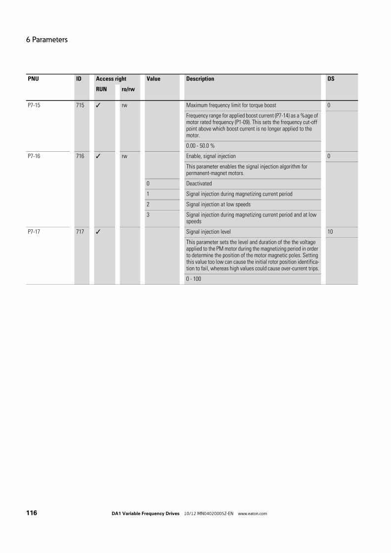
6 Parameters
116 DA1 Variable Frequency Drives 10/12 MN04020005Z-EN www.eaton.com
P7-15 715 rw Maximum frequency limit for torque boost 0
Frequency range for applied boost current (P7-14) as a %age of motor rated frequency (P1-09). This sets the frequency cut-off point above which boost current is no longer applied to the motor.
0.00 - 50.0 %
P7-16 716 rw Enable, signal injection 0
This parameter enables the signal injection algorithm for permanent-magnet motors.
0 Deactivated
1 Signal injection during magnetizing current period
2 Signal injection at low speeds
3 Signal injection during magnetizing current period and at low speeds
P7-17 717 Signal injection level 10
This parameter sets the level and duration of the the voltage applied to the PM motor during the magnetizing period in order to determine the position of the motor magnetic poles. Setting this value too low can cause the initial rotor position identifica-tion to fail, whereas high values could cause over-current trips.
0 - 100
PNU ID Access right Value Description DS
RUN ro/rw

6 Parameters
DA1 Variable Frequency Drives 10/12 MN04020005Z-EN www.eaton.com 117
Parameter group P8 – Ramps
P8-01 801 rw Second acceleration time (acc2) 5.0
Used to define the ramp time for acceleration ramp 2 (acc2). The time set in this parameter is defined as the time required for the ramp to go from = to the frequency set in P1-09.
0.00 - 600 s
P8-02 802 rw Transition frequency (acc1 → acc2) 0.0
Defines the speed boundary (frequency limit) at which the acceleration ramp changes from ramp 1 to ramp 2.
0.00 - P1-02
P8-03 803 rw Third acceleration time (acc3) 5.0
like P8-01
0.00 - 600 s
P8-04 804 rw Transition frequency (acc2 → acc3) 0.0
Defines the speed boundary (frequency limit) at which the acceleration ramp changes from ramp 2 to ramp 3.
0.00 - P1-02
P8-05 805 rw Fourth acceleration time (acc4) 5.0
like P8-01
0.00 - 600 s
P8-06 806 rw Transition frequency (acc3 → acc4) 0.0
Defines the speed boundary (frequency limit) at which the acceleration ramp changes from ramp 3 to ramp 4.
0.00 - P1-02
P8-07 807 rw Fourth deceleration time (dec4) 5.0
Used to define the ramp time for deceleration ramp 4 (dec4). The time set in this parameter is defined as the time required for the ramp to go from the frequency set in P1-09 to 0.
0.00 - 600 s
P8-08 808 rw Transition frequency (dec4 → dec3) 0.0
Defines the speed boundary (frequency limit) at which the deceleration ramp changes from ramp 4 to ramp 3.
0.00 - P1-03
P8-09 809 rw Third deceleration time (dec3) 5.0
Like P8-07
0.00 - 600 s
P8-10 810 rw Transition frequency (dec3 → dec2) 0.0
Defines the speed boundary (frequency limit) at which the deceleration ramp changes from ramp 3 to ramp 2.
0.00 - P1-04
PNU ID Access right Value Description DS
RUN ro/rw

6 Parameters
118 DA1 Variable Frequency Drives 10/12 MN04020005Z-EN www.eaton.com
P8-11 811 rw Second deceleration time (dec2) 5.0
Like P8-07
0.00 - 600 s
P8-12 812 rw Transition frequency (dec2 → dec1) 0.0
Defines the speed boundary (frequency limit) at which the deceleration ramp changes from ramp 2 to ramp 1.
0.00 - P1-05
P8-13 813 rw Ramp selection when there is a preset speed 0
When set to 0, Acceleration and deceleration ramps 1 are selected by default but can be reconfigured using Group 9 parameters. When set to 1, the acceleration and deceleration ramps are selected according to the parameters set in P8-01 to P8-12.
0 Deactivated
1 Activated
Parameter group P9 – Control
P9-01 901 – rw Control source - enable 1
Defines the source of the signal to be used for the activation input
0 safe input
1 Digital input 1 (DI1)
2 Digital input 2 (DI2)
3 Digital input 3 (DI3)
4 Digital input 4 (DI4)
5 Digital input 5 (DI5)
6 Digital input 6 (DI6)
7 Digital input 7 (DI7)
8 Digital input 8 (DI8)
PNU ID Access right Value Description DS
RUN ro/rw

6 Parameters
DA1 Variable Frequency Drives 10/12 MN04020005Z-EN www.eaton.com 119
P9-02 902 – rw Control source - quick stop 0
Defines the source of the signal to be used for the quick stop input
0 OFF / deactivated
1 Digital input 1 (DI1)
2 Digital input 2 (DI2)
3 Digital input 3 (DI3)
4 Digital input 4 (DI4)
5 Digital input 5 (DI5)
6 Digital input 6 (DI6)
7 Digital input 7 (DI7)
8 Digital input 8 (DI8)
9 Analog output 1 (AO1)
10 Analog output 2 (AO2)
11 Digital output 1 (DO1)
12 Digital output 2 (DO2)
13 Digital output 3 (DO3)
14 Digital output 4 (DO4)
15 Digital output 5 (DO5)
16 ON / active
17 User register 1
18 User Register 2
19 User register 3
20 User register 4
21 User register 5
22 User register 6
23 User Register 7
24 User register 8
25 User register 9
P9-03 903 – rw Control source - start signal 1 (FWD) 1
Defines the source of the signal to be used for the start signal 1 (FWD) input.
like P9-02
P9-04 904 – rw Control source – start signal 2 (REV) 0
Defines the source of the signal to be used for the start signal 2 (REV) input.
like P9-02
PNU ID Access right Value Description DS
RUN ro/rw

6 Parameters
120 DA1 Variable Frequency Drives 10/12 MN04020005Z-EN www.eaton.com
P9-05 905 – rw Control source - stay-put function (for P9-03 and P9-04) 0
0 = OFF / deactivated
1 = ON / active
P9-06 906 – rw Control source - enable (REV) 2
Defines the source of the signal to be used for the enable (REV) input
like P9-02
P9-07 907 – rw Control source - reset 1
Defines the source of the signal to be used for the reset input
like P9-02
P9-08 908 – rw Control source – external fault 0
Defines the source of the signal to be used for the external fault input
like P9-02
P9-09 909 – rw Control source terminal mode 16
Defines the source of the signal used for the terminal mode input.
like P9-02
P9-10 910 – rw Source - speed 1 0
0 Analog input 1 (AI1)
1 Analog input 2 (AI2)
2 Fixed frequency 0
3 Operating unit
4 PID controller output
5 Master speed
6 Field bus
7 From internal PLC program
8 Frequency input speed reference value
9 Fixed frequency 1 (FF1)
10 Fixed frequency 2 (FF2)
11 Fixed frequency 3 (FF3)
12 Fixed frequency 4 (FF4)
13 Fixed frequency 5 (FF5)
14 Fixed frequency 6 (FF6)
15 Fixed frequency 7 (FF7)
16 Fixed frequency 8 (FF8)
P9-11 911 – rw Source - speed 2 2
like P9-10
PNU ID Access right Value Description DS
RUN ro/rw

6 Parameters
DA1 Variable Frequency Drives 10/12 MN04020005Z-EN www.eaton.com 121
P9-12 912 – rw Source - speed 3 0
like P9-10
P9-13 913 – Source - speed 4 0
like P9-10
P9-14 914 – rw Source - speed 5 0
like P9-10
P9-15 915 – rw Source - speed 6 0
like P9-10
P9-16 916 – rw Source - speed 7 0
like P9-10
P9-17 917 – rw Source - speed 8 0
like P9-10
P9-18 918 – rw Speed - input 0 3
like P9-02
P9-19 919 – rw Speed - input 1 0
like P9-02
P9-20 920 – rw Speed - input 2 0
like P9-02
P9-21 921 – rw Fixed frequency 0 5
like P9-02
P9-22 922 – rw Fixed frequency 1 0
like P9-02
P9-23 923 – rw Fixed frequency 2 0
like P9-02
P9-24 924 – rw Acceleration ramp input 0 0
like P9-02
P9-25 925 – rw Acceleration ramp input 1 0
like P9-02
P9-26 926 – rw Deceleration time input 0 0
like P9-02
P9-27 927 – rw Deceleration time input 1 0
like P9-02
P9-28 928 – rw Control source - Up-pushbutton 0
like P9-02
P9-29 929 – rw Control source - Down-pushbutton 0
like P9-02
P9-30 930 – rw FWD limit switch 0
like P9-02
PNU ID Access right Value Description DS
RUN ro/rw

6 Parameters
122 DA1 Variable Frequency Drives 10/12 MN04020005Z-EN www.eaton.com
P9-31 931 – rw REV limit switch 0
like P9-02
P9-32 932 – reserved 0
P9-33 933 – rw Control source - analog output 1 (AO1) 0
0 Value from P2-11
1 User Analog Output 1 (Digital)
2 User Analog Output 1 (Analog)
P9-34 934 – rw Source - analog output 2 (AO2) 0
0 Value from P2-13
1 User Analog Output 1 (Digital)
2 User Analog Output 1 (Analog)
P9-35 935 – rw Control source - Relay 1 0
0 Value from P2-15
1 From internal PLC program
P9-36 936 – rw Control source - Relay 2 0
0 Value from P2-18
1 user-definable (PLC)
P9-37 937 – rw Control source - scaling 0
0 Value from P2-22
1 From internal PLC program
P9-38 938 – rw Source - PID setpoint value 0
0 Value from P3-05
1 user-definable
P9-39 939 – rw Source - PID feedback 0
0 Value from P3-10
1 From internal PLC program
P9-40 940 – rw Source - torque control reference 0
0 Value from P4-06
1 From internal PLC program
P9-41 941 – rw Function choices - Relay output 3, 4, 5 0
0 Relay 1 → Variable frequency drive OK
Relay 2 → Variable frequency drive tripped
Relay 3 → Variable frequency drive released
1 From internal PLC program
PNU ID Access right Value Description DS
RUN ro/rw

6 Parameters
DA1 Variable Frequency Drives 10/12 MN04020005Z-EN www.eaton.com 123
Parameter group P0 – Monitor
P0-01 1 Analog input 1 %
Displays the level of the signal level applied to analog input 1 (AI1, terminal 6) after scaling and offsets have been applied.
P0-02 2 Analog input 2 (AI2) %
Displays the level of the signal level applied to analog input 2 (AI2, terminal 10) after scaling and offsets have been applied.
P0-03 3 Digital inputs 1 - 5; status DI1, DI2, DI3, DI4 DI5 00000
Displays the status of the variable frequency drive digital and analog inputs, including those available on the optional extended I/O module (DXA-EXT-3DI1RO). The value on the starting with the left hand side digit is digital input 1 (DI1).
P0-04 4 Frequency reference value Hz
Displays the set point reference input applied to the drive internal speed controller.
P0-05 5 Torque setpoint value %
Displays the set point reference input applied to the drive internal torque controller.
P0-06 6 Digital speed reference value (motor potentiometer) Hz
Displays the value of the drive internal Motorised Pot (used for keypad) speed reference.
P0-07 7 Field bus communication reference speed Hz
Displays the setpoints being received by the drive via the currently active field bus interface.
P0-08 8 PID setpoint value %
Displays the setpoint input to the PID controller.
P0-09 9 PID feedback %
Displays the Feedback input signal to the PID controller
P0-10 10 PID Output %
Displays the output level of the PID controller
P0-11 11 Motor voltage V
Displays the instantaneous output voltage from the variable frequency drive to the motor
P0-12 12 Output torque (calculated value) %
Displays the instantaneous output torque level produced by the motor
P0-13 13 Fault log
Displays the variable frequency drive's last four error codes. See the Faults section for more information.
P0-14 14 Magnetizing current (Id) A
Displays the motor magnetizing current, provided that an auto tune has been successfully completed.
PNU ID Access right Value Description DS
RUN ro/rw

6 Parameters
124 DA1 Variable Frequency Drives 10/12 MN04020005Z-EN www.eaton.com
P0-15 15 Rotor current (Iq) A
Displays the motor Rotor (torque producing) current, provided that an auto tune has been successfully completed.
P0-16 16 DC link voltage ripple V
Displays the level of ripple present on the DC bus voltage.This parameter is used by the drive for various internal protec-tion and monitoring functions.
P0-17 17 Stator resistance (Rs) Ω
Displays the measured motor stator resistance, provided that an auto tune has been successfully completed.
P0-18 18 Stator inductance H
Displays the measured motor stator inductance, provided that an auto tune has been successfully completed.
P0-19 19 Rotor resistance Ω
Displays the measured motor rotor resistance, provided that an auto tune has been successfully completed.
P0-20 20 The variable frequency drive's current DC link voltage V
P0-21 21 Unit Temperature °C
Displays the measured instantaneous heatsink temperature of the variable frequency drive.
P0-22 22 Remaining time until servicing is required h
Displays the value of P6-24 minus the variable frequency drive’s operating time.
P0-23 23 Time heat sink temperature > 85 °C HH:MM:SS
Displays the amount of time in hours and minutes for which the drive has been operating during its lifetime, where the heatsink temperature has been in excess of 85 °C. This parameter is used by the drive for various internal protection and monitoring functions.
P0-24 24 Operating time at ambient temperature > 85 °C HH:MM:SS
Displays the total accumulated time in hours and minutes for which the drive has been operating with the internal ambient temperature in excess of 80 °C. This parameter is used by the drive for various built-in protection and monitoring functions.
P0-25 25 Motor shaft speed (calculated value in rpm) rpm
In vector control mode, this parameter displays either the esti-mated rotor speed of the motor if no encoder feedback is present, or the measured rotor speed if the optional Encoder feedback interface Option is fitted.
P0-26 26 kWh-meter, up to 1000 kWh then P0-27 on 1 kWh
Displays the energy consumed by the drive, in kWh.The first value shows the energy consumed since the counter was last reset. The second value shows the total energy consumed since the unit was made. If the value reaches 1,000 kWh, the counter will be reset to 0.0 and the value in P0-27 (MWh counter) will be incremented by 1.
PNU ID Access right Value Description DS
RUN ro/rw

6 Parameters
DA1 Variable Frequency Drives 10/12 MN04020005Z-EN www.eaton.com 125
P0-27 27 MWh counter, P0-26 = 1000 → P0-27 = 1 MWh
Displays the energy consumed by the drive, in MWh.The first value shows the energy consumed since the counter was last reset. The second value shows the total energy consumed since the unit was made.
P0-28 28 Software version and checksum of the drive
P0-29 29 Type details of the drive
P0-30 30 Serial number of the drive
P0-31 31 Operating time after default settings HH:MM:SS
Displays the total operating time of the drive since the date of manufacture in Hours, Minutes and Seconds. Pressing the Up key on the drive keypad will change the display from “Hours“ to “Minutes and Seconds“.
P0-32 32 Operating time since the last trip 1 HH:MM:SS
Displays the total operating time of the drive since the last Trip or Power down occurred in Hours, Minutes and Seconds. Pressing the Up key on the drive keypad will change the display from “Hours“ to “Minutes and Seconds“
P0-33 33 Operating time since the last trip 2 HH:MM:SS
Displays the total operating time of the drive since the last Trip occurred in Hours, Minutes and Seconds. Pressing the Up key on the drive keypad will change the display from “Hours“ to “Minutes and Seconds“
P0-34 34 Operating time after last enable HH:MM:SS
Displays the total operating time of the drive since the last drive Enable signal was applied. Pressing the Up key on the drive keypad will change the display from “Hours“ to “Minutes and Seconds“.
P0-35 35 Runtime of the fan HH:MM:SS
Displays the total operating time of the drive's integrated cooling fan in hours, minutes, and seconds.Pressing the Up key on the drive keypad will change the display from “Hours“ to “Minutes and Seconds“.
P0-36 36 DC bus voltage log (256 ms)
DC Bus voltage log, recording the most recent 8 samples of the DC bus voltage prior to a drive trip condition occurring.The sample interval is 256 ms.
P0-37 37 DC bus voltage ripple log (20 ms)
DC Bus voltage ripple log, recording the most recent 8 samples of the DC bus voltage ripple prior to a drive trip condition occur-ring. The sample interval is 20 ms.
P0-38 38 Heatsink temperature log (30 s)
Heatsink temperature log, recording the most recent 8 samples of the heatsink temperature prior to a drive trip condition occur-ring. The sample interval is 30 s.
PNU ID Access right Value Description DS
RUN ro/rw

6 Parameters
126 DA1 Variable Frequency Drives 10/12 MN04020005Z-EN www.eaton.com
P0-39 39 Protocol of ambient air temperature (30 s)
Ambient temperature log, recording the most recent 8 samples of the drive internal ambient temperature prior to a drive trip condition occurring. The sample interval is 30 s.
P0-40 40 Motor current log (256 ms)
Motor current log, recording the most recent 8 samples of the Motor current prior to a drive trip condition occurring.
P0-41 41 FLT counter, overcurrent
Displays the number of overcurrent (O-I) trips which have occurred since the date of manufacture
P0-42 42 FLT counter, overvoltage
Displays the number of Over-voltage (O-Volt) trips which have occurred since the date of manufacture
P0-43 43 FLT counter, undervoltage
Displays the number of undervoltage (U-Volt) trips which have occurred since the date of manufacture
P0-44 44 FLT counter, overtemperature
Displays the number of Heatsink overtemperature (O-t) trips which have occurred since the date of manufacture
P0-45 45 FLT counter, braking transistor, overcurrent
Displays the number of brake chopper short-circuit (b O-I) trips which have occurred since the date of manufacture
P0-46 46 FLT counter, ambient temperature
Displays the number of drive internal ambient overtemperature (O-t) trips which have occurred since the date of manufacture.
P0-47 47 I/O communication fault meter
Displays the number of communication errors detected by the I/O processor in messages received from the power stage processor since the last power up.
P0-48 48 DSP communication fault meter
Displays the number of communication errors detected by the Power Stage processor in messages received from the I/O processor since the last power up.
P0-49 49 FLT counter, Modbus RTU communication
Displays the number of communication errors detected by the I/O processor in messages received on the Modbus channel since the last power up.
P0-50 50 FLT counter, CANopen communication
Displays the number of communication errors detected by the I/O processor in messages received on the CANbus channel since the last power up.
P0-51 51 reserved
P0-52 52 reserved
PNU ID Access right Value Description DS
RUN ro/rw

6 Parameters
DA1 Variable Frequency Drives 10/12 MN04020005Z-EN www.eaton.com 127
P0-53 53 U phase shift
L1 phase current offset and reference
P0-54 54 V phase shift
L2 phase current offset and reference
P0-55 55 reserved
P0-56 56 Braking chopper - maximum “on“ time
Displays the maximum Chopper closing delay in ms and the duty cycle ratio
P0-57 57 Ud/Uq
P0-58 58 Measured encoder speed Hz
Displays the measured encoder speed in Hz or rpm, if the encoder option module (DXA-EXT-ENCOD) is fitted and enabled.
P0-59 59 Frequency input speed reference value Hz
P0-60 60 Calculated slip speed in Hz or rpm Hz
P0-61 61 Speed boost for hoisting gear Hz
Displays the boost speed applied in Hoist control mode
P0-62 62 Droop speed in Hz or rpm Hz
P0-63 63 Speed reference value post ramp Hz
Displays the post ramp speed reference in Hz or rpm.
P0-64 64 Current switching frequency kHz
Displays the current RMS switching frequency. This frequency can be lower than the value set in P2-24 if reduced by the thermal feedback function (enabled in P6-02).
P0-65 65 Lifespan of the variable frequency drive HH:MM:SS
Displays the time for which the drive has been powered up in Hours, Minutes and Seconds since date of manufacture
P0-66 66 ID of the PLC program 0
Displays the program ID of the user's PLC program. The user can specify this ID in the “drivesConnect“ computer program while in PLC program mode.
P0-67 67 Field bus torque setpoint value
Displays the field bus interface's torque reference value.
P0-68 68 User ramp value
Displays the user ramp value received by the field bus inter-face.This ramp function will only be enabled if P5-07 = 1 (enabled).
P0-69 69 I2C error counter
Displays the I2C error counter value since last power up.
P0-70 70 Module identification code
Identification code of the module
PNU ID Access right Value Description DS
RUN ro/rw
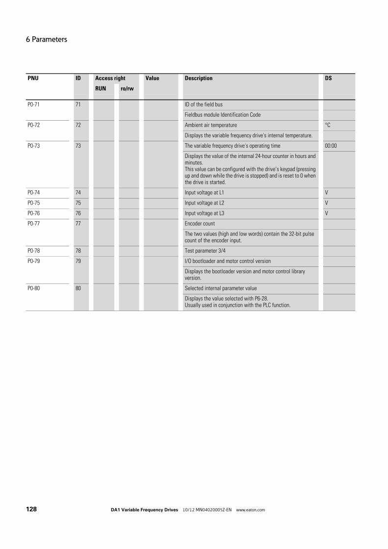
6 Parameters
128 DA1 Variable Frequency Drives 10/12 MN04020005Z-EN www.eaton.com
P0-71 71 ID of the field bus
Fieldbus module Identification Code
P0-72 72 Ambient air temperature °C
Displays the variable frequency drive's internal temperature.
P0-73 73 The variable frequency drive's operating time 00:00
Displays the value of the internal 24-hour counter in hours and minutes.This value can be configured with the drive’s keypad (pressing up and down while the drive is stopped) and is reset to 0 when the drive is started.
P0-74 74 Input voltage at L1 V
P0-75 75 Input voltage at L2 V
P0-76 76 Input voltage at L3 V
P0-77 77 Encoder count
The two values (high and low words) contain the 32-bit pulse count of the encoder input.
P0-78 78 Test parameter 3/4
P0-79 79 I/O bootloader and motor control version
Displays the bootloader version and motor control library version.
P0-80 80 Selected internal parameter value
Displays the value selected with P6-28.Usually used in conjunction with the PLC function.
PNU ID Access right Value Description DS
RUN ro/rw

6 Parameters
6.1 Operating unit
DA1 Variable Frequency Drives 10/12 MN04020005Z-EN www.eaton.com 129
6.1 Operating unit
The following figure shows the elements of the DA1 variable frequency drive integrated operating unit.
Figure 49: Operating unit view
Table 11: Operating unit elements
Operating unit element Explanation
Six-digit 7-segment LED display
Motor starter with pre-selected operating direction if parameter P1-12 = 1 (FWD) or P1-12 = 2 (FWD / REV).
Notes:• Enable with +24 V on control signal terminal 2 (DI1)• P1-12 = 2: The first time it is pressed (commissioning, parameter reset), a
clockwise rotating field (FWD) will always be activated. Only after it is pressed for a second time will the direction of the rotating field change to a counterclockwise rotating field (REV). (This setting will be retained even after the supply voltage is switched off.)
• Stops the running motor if P1-12 = 1 or P1-12 = 2• Reset – Resetting after an error message
• Activate parameter input (editing mode)• Activate parameter value, change (display value flashes)• Confirm (store) and activate configured value
• Increment numeric value or parameter number• Increase output frequency / motor speed if P1-12 = 1 or P1-12 = 2
• Decrement numeric value or parameter number• Reduce output frequency / motor speed if P1-12 = 1 or P1-12 = 2

6 Parameters
6.1 Operating unit
130 DA1 Variable Frequency Drives 10/12 MN04020005Z-EN www.eaton.com
6.1.1 Display unitThe display unit is a 7-segment LED display with five decimal points. The LED segments are red.
Figure 50: 7-segment LED display
6.1.2 Menu NavigationWhen the specified supply voltage (L1/L, L2/N, L3 connection terminals) is applied, the DA1 variable frequency drive will automatically perform a self-test: The LED display will light up and, depending on the selected operating mode, will display Stop or the appropriate value.
6.1.3 Setting parametersThe following table shows a good example of the general execution for selecting and setting parameters.
→ When operating values are displayed (i.e. STOP is not displayed), the variable frequency drive will issue an automatic start com-mand.
→ The flashing digit on the right indicates that the value being dis-played can be changed with the arrow buttons (Up or Down ).
Sequence Commands Indicator Description
0 Stop status: The variable frequency drive is ready for operation.
1 Hold down the OK button for about a second.Parameter P1-01 will be displayed (the digit on the right, “1“, will flash)
Press OK buttonThe display will switch to H 50.0 (= 50 Hz), the digit on the right, “0“, will flash.The value can be confirmed and automatically stored by pressing the OK pushbutton. The display will jump back to the parameter designation (P1-01).
2 The numerical first value is always shown from the selected main menu.
Example: PAR main menu, parameter P1-01
→ Activate and save your changes with the OK pushbutton.

6 Parameters
6.1 Operating unit
DA1 Variable Frequency Drives 10/12 MN04020005Z-EN www.eaton.com 131
6.1.4 Parameter selectionParameter P-14 is used to select between a limited range of parameters (P1-14 = 0), the advanced parameters (P1-14 = P2-40, DS = 101), or all parameters (P1-14 = P6-30, DS = 201).
Parameter P2-40 or P6-30 is used to change the access code used to access all the parameters. Once you confirm parameter P2-40 or P6-30, the reduced parameters will be locked.
You can use parameter P2-39 to block access to all parameters, with the exception of parameter P1-14 (read-only).

6 Parameters
6.2 Digital and analog inputs
132 DA1 Variable Frequency Drives 10/12 MN04020005Z-EN www.eaton.com
6.2 Digital and analog inputs
Parameter P1-13 is used to configure the mode of operation and function of both the digital and analog inputs (Table 12, page 133). The configured value will depend on parameter P1-12.
Figure 51: Digital and analog inputs
The operation of the DA1 variable frequency drive via control signal terminals (P1-12 = 0, P1-13 = 11) is active with default settings:
• DI1 (control signal terminal 2):FWD (Start enable clockwise rotating field)
• DI2 (control signal terminal 3):REV (Start enable anti-clockwise rotating field)
• DI3 (control signal terminal 4):FF1 or FF2 (switching between setpoint sources)
• AI1/DI4 (control signal terminal 6): analog setpoint input (0 - 10 V)• DI5/AI2 (control signal terminal 10):
FF1 or FF2 (switching between fixed frequency 1 (FF1 = P2-01, DS = 5 Hz) and fixed frequency 2 (FF2 = P2-02, DS = 10 Hz))
When control signal terminal 2 (FWD) and control signal terminal 3 (REV) are activated at the same time, the default settings will activate quick stop dec2 (P2-25).
2
DI1
FWD
+24
V
3
DI2
REV
10
DI5
AI2
FF2
6
AI1
DI4
f-S
oll
1
+24
V O
ut<
100
mA
4
DI3
FF1/
2
CPU0.
..+10
V/2
0 m
A
P1-12 = 0AI1 DI4DI5 AI2
P1-13 = 0, 2, 7 ... 10, 12, 17 ... 20P1-13 = 0, 3, 6, 13, 15

6 Parameters
6.2 Digital and analog inputs
DA1 Variable Frequency Drives 10/12 MN04020005Z-EN www.eaton.com 133
Table 12: Parameter P1-13 configuration
P1-13 DI1 DI2 DI3 AI1/DI 5 DI4/AI2 Fixed frequen-cies
0 user-definable user-definable user-definable user-definable user-definable
1 0 = Stop1 = Run
0 = Forward 1 = Reverse
0 = Selected setpoint source1 = Fixed frequency 1/2
AI 1 setpoint value 0 = Fixed frequency 11 = Fixed frequency 2
2 0 = Stop1 = Run
0 = Forward 1 = Reverse
0 0 0 FF 1
1 0 0 FF 2
0 1 0 FF 3
1 1 0 FF 4
0 0 1 FF 5
1 0 1 FF 6
0 1 1 FF 7
1 1 1 FF 8
3 0 = Stop1 = Run
0 = Forward 1 = Reverse
0 = Selected setpoint source1 = Fixed frequency 1
Setpoint value AI1 Analog torque control refer-ence
4 0 = Stop1 = Run
0 = Forward 1 = Reverse
0 = Selected setpoint source1 = Fixed frequency 1
Setpoint value AI1 0 = Deceleration time 11 = Deceleration time 2
5 0 = Stop1 = Run
0 = Forward 1 = Reverse
0 = Selected setpoint source1 = Analog input 2
Setpoint value AI1 Setpoint value AI2
6 0 = Stop1 = Run
0 = Forward 1 = Reverse
0 = Selected setpoint source1 = Fixed frequency 1
Setpoint value AI1 External fault 0 = Fault1 = Run
7 0 = Stop1 = Run
0 = Forward 1 = Reverse
0 0 External fault 0 = Fault1 = Run
FF 1
1 0 FF 2
0 1 FF 3
1 1 FF 4
8 0 = Stop1 = Run
0 = Forward 1 = Reverse
0 0 0 = Deceleration time 11 = Deceleration time 2
FF 1
1 0 FF 2
0 1 FF 3
1 1 FF 4
9 0 = Stop1 = Run
0 = Forward 1 = Reverse
0 0 0 = Selected setpoint source1 = Fixed frequency1 - 4
FF 1
1 0 FF 2
0 1 FF 3
1 1 FF 4
10 0 = Stop1 = Run
0 = Forward 1 = Reverse
1 = Increase setpoint value
1 = Decrease setpoint value
0 = Selected setpoint source1 = Fixed frequency 1
11 0 = Stop1 = Run FWD
0 = Stop1 = Run REV
0 = Selected setpoint source1 = Fixed frequency 1 / 2
AI 1 setpoint value 0 = Fixed frequency 11 = Fixed frequency 2

6 Parameters
6.2 Digital and analog inputs
134 DA1 Variable Frequency Drives 10/12 MN04020005Z-EN www.eaton.com
12 0 = Stop1 = Run FWD
0 = Stop1 = Run REV
0 0 0 FF 1
1 0 0 FF 2
0 1 0 FF 3
1 1 0 FF 4
0 0 1 FF 5
1 0 1 FF 6
0 1 1 FF 7
1 1 1 FF 8
13 0 = Stop1 = Run FWD
0 = Stop1 = Run REV
0 = Selected setpoint source1 = Fixed frequency 1
Setpoint value AI1 Analog torque control refer-ence
14 0 = Stop1 = Run FWD
0 = Stop1 = Run REV
0 = Selected setpoint source1 = Fixed frequency 1
Setpoint value AI1 0 = Deceleration time 11 = Deceleration time 2
15 0 = Stop1 = Run FWD
0 = Stop1 = Run REV
0 = Selected setpoint source1 = Analog input 2
Setpoint value AI1 Setpoint value AI2
16 0 = Stop1 = Run FWD
0 = Stop1 = Run REV
0 = Selected setpoint source1 = Fixed frequency 1
Setpoint value AI1 External fault 0 = Fault1 = Run
17 0 = Stop1 = Run FWD
0 = Stop1 = Run REV
0 0 External fault 0 = Fault1 = Run
FF 1
1 0 FF 2
0 1 FF 3
1 1 FF 4
18 0 = Stop1 = Run FWD
0 = Stop1 = Run REV
0 0 0 = Deceleration time 11 = Deceleration time 2
FF 1
1 0 FF 2
0 1 FF 3
1 1 FF 4
19 0 = Stop1 = Run FWD
0 = Stop1 = Run REV
0 0 0 = Selected setpoint source1 = Fixed frequency 1 - 4
FF 1
1 0 FF 2
0 1 FF 3
1 1 FF 4
20 0 = Stop1 = Run FWD
0 = Stop1 = Run REV
1 = Increase setpoint value
2 = Decrease setpoint value
0 = Selected setpoint source1 = Fixed frequency 1
21 Pushbutton:1 = Run FWD
Pushbutton: 0 = Stop Pushbutton:1 = Run REV
AI 1 setpoint value 0 = Selected setpoint source1 = Fixed frequency 1
P1-13 DI1 DI2 DI3 AI1/DI 5 DI4/AI2 Fixed frequen-cies

6 Parameters
6.2 Digital and analog inputs
DA1 Variable Frequency Drives 10/12 MN04020005Z-EN www.eaton.com 135
6.2.1 Digital Input (DI)Control signal terminals 2, 3, 4, 6 and 10 can be used as digital inputs (DI). The digital inputs’ function and mode of operation are configured in para-meter P1-13.
Example
Desired options:
• Clockwise rotating field (FWD)• Anticlockwise rotating field (REV)• a fixed frequency• External fault• Setpoint value via AI1
Figure 52: Example of an external fault (EXT)
Table 13: Digital input wiring (P1-12 = 0)
• DI1 (control signal terminal 2):FWD (Forward = Start enable clockwise rotating field)
• DI2 (control signal terminal 3):REV (Reverse = Start enable anti-clockwise rotating field)
• DI3 (control signal terminal 4): FF1 (fixed frequency 1)• DI5 (control signal terminal 10): external fault• AI1 (control signal terminal 6): analog setpoint value
2
DI1
FWD
+24
V
3
DI2
REV
4
DI3
FF1
10
DI5
EXT
6
AI1
f-S
oll
1
+24
V O
ut<
100
mA
0...+
10 V
/20
mA
P1-12 = 0P1-13 = 16
P1-13 DI1 DI2 DI3 DI5 AI1
16 0 = locked1 = Start enable FWD
0 = locked1 = Start enable REV
0 = Selected setpoint source1 = Fixed frequency 1
external fault:0 = Fault1 = Enable
Setpoint value AI1(0 - 10 V)
DI1 + DI2 = Quick stop (P-24)

6 Parameters
6.2 Digital and analog inputs
136 DA1 Variable Frequency Drives 10/12 MN04020005Z-EN www.eaton.com
6.2.2 Analog Input (AI)Control signal terminals 6 and 10 can be used as analog inputs (AI). The cor-responding signal range will depend on parameter P2-30 for analog input AI1 and parameter P2-33 for analog input AI2.
The reference potential for the two analog inputs AI1 and AI2 is 0 V (control signal terminals 7 and 9).
With the default settings, control signal terminal 6 (AI1) will be configured for a setpoint voltage of 0 to +10 V DC (P2-30) and control signal terminal 10 as a digital input (DI5).
Example
Desired options:
• Analog input AI2 suitable for 4 to 20 mA with wire breakage monitoring.• Switching the setpoint source between AI1 and AI2 via DI3.
Figure 53: Switching setpoint sources
Table 14: Analog and digital input wiring (P1-12 = 0, P2-30 = t4-20)
• DI1 (control signal terminal 2):FWD (Forward = Start enable clockwise rotating field)
• DI2 (control signal terminal 3):REV (Reverse = Start enable anti-clockwise rotating field)
• DI3 (control signal terminal 4):AI1 / AI2 (change of setpoint source from AI1 to AI2)
• AI1 (control signal terminal 6): analog setpoint value 1• AI2 (control signal terminal 10): analog setpoint value 2
→ The function of control signal terminals 6 and 10 is defined by the selection made in parameter P1-13 and depends on the con-trol mode in parameter P1-12.
+24
V
4
DI3
5
AI1
AI2
10
AI2
f-S
oll 2
f-S
oll 1
1
+24
V O
ut<
100
mA
0...+
10 V
/20
mA
P1-12 = 0P1-15 = 15P2-30 =
P1-13 DI1 DI2 DI3 AI1 AI2
15 0 = locked1 = Start enable FWD
0 = locked1 = Start enable REV
0 = AI11 = AI2
Setpoint value AI1(0 - 10 V)
Setpoint value AI2(4 - 20 mA)

6 Parameters
6.2 Digital and analog inputs
DA1 Variable Frequency Drives 10/12 MN04020005Z-EN www.eaton.com 137
6.2.2.1 Scaled value range (AI1/AI2)The following graphs show examples of the curve characteristics of the scaled and non-scaled input signals.
Example: P2-31 = 200 %
If parameter P2-30 is configured for a 0 - 10 V signal and parameter P2-31 is set to 200 %, a 5 V input will result in the variable frequency drive running at its maximum frequency / speed (P1-01). Values lower than 100 % limit the maximum frequency; values greater than 100 % are used for low signal lev-els, e.g. for sensors with a 0 to 5 V output.
Figure 54: Scaled input signal
100 % f
AI1
(10 V)
5 V ≙ 100 %
P1-01
P2-31
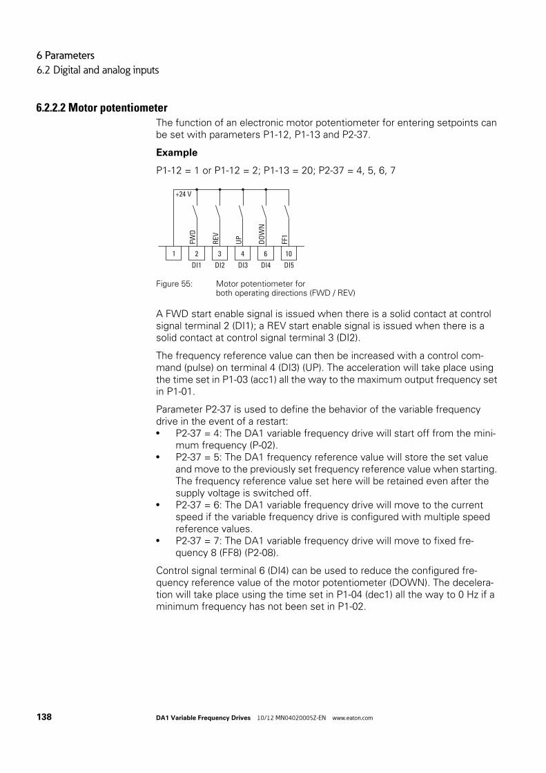
6 Parameters
6.2 Digital and analog inputs
138 DA1 Variable Frequency Drives 10/12 MN04020005Z-EN www.eaton.com
6.2.2.2 Motor potentiometerThe function of an electronic motor potentiometer for entering setpoints can be set with parameters P1-12, P1-13 and P2-37.
Example
P1-12 = 1 or P1-12 = 2; P1-13 = 20; P2-37 = 4, 5, 6, 7
Figure 55: Motor potentiometer forboth operating directions (FWD / REV)
A FWD start enable signal is issued when there is a solid contact at control signal terminal 2 (DI1); a REV start enable signal is issued when there is a solid contact at control signal terminal 3 (DI2).
The frequency reference value can then be increased with a control com-mand (pulse) on terminal 4 (DI3) (UP). The acceleration will take place using the time set in P1-03 (acc1) all the way to the maximum output frequency set in P1-01.
Parameter P2-37 is used to define the behavior of the variable frequency drive in the event of a restart:• P2-37 = 4: The DA1 variable frequency drive will start off from the mini-
mum frequency (P-02).• P2-37 = 5: The DA1 frequency reference value will store the set value
and move to the previously set frequency reference value when starting. The frequency reference value set here will be retained even after the supply voltage is switched off.
• P2-37 = 6: The DA1 variable frequency drive will move to the current speed if the variable frequency drive is configured with multiple speed reference values.
• P2-37 = 7: The DA1 variable frequency drive will move to fixed fre-quency 8 (FF8) (P2-08).
Control signal terminal 6 (DI4) can be used to reduce the configured fre-quency reference value of the motor potentiometer (DOWN). The decelera-tion will take place using the time set in P1-04 (dec1) all the way to 0 Hz if a minimum frequency has not been set in P1-02.
DI1 DI2 DI4 DI5
2 3
FWD
REV
+24 V
1 6D
OW
NDI3
4
UP
10
FF1

6 Parameters
6.2 Digital and analog inputs
DA1 Variable Frequency Drives 10/12 MN04020005Z-EN www.eaton.com 139
Figure 56: Motor potentiometer example
If a minimum frequency has been configured (P1-02), the motor potentio-meter will always start at f = 0 Hz. After the configured minimum frequency is exceeded, the motor potentiometer will work within the range up to the maximum frequency (P1-01). The frequency will not fall below the minimum frequency value unless the start enable (DI1) is switched off.
Figure 57: Motor potentiometer with fmin limit
f[Hz]
DI3
DI4
DI1
fmax
0 Hz
P1-01
P1-04
UP UP UP
DOWN DOWN
START FWD
P1-03
f[Hz]
DI3
DI4
DI1
fmax
0 Hz
fmin
UP UP UP
DOWN
START FWD
P1-01
P1-02

6 Parameters
6.2 Digital and analog inputs
140 DA1 Variable Frequency Drives 10/12 MN04020005Z-EN www.eaton.com
6.2.2.3 Two-wire controlThe parameters must be set as follows for the so-called two-wire control:
P1-13 DI1 DI2 DI3 AI1/DI4 AI2/DI5 Notes
1 0 = Stop1 = Run
0 = FWD1 = REV
0 = Selected setpoint source1 = Fixed frequency 1 or 2
AI 1 setpoint value
0 = Fixed frequency 1
1 = Fixed frequency 2
2 0 = Stop1 = Run
0 = FWD1 = REV
0 0 0 Fixed frequency 1
1 0 0 Fixed frequency 2
0 1 0 Fixed frequency 3
1 1 0 Fixed frequency 4
0 0 1 Fixed frequency 5
1 0 1 Fixed frequency 6
0 1 1 Fixed frequency 7
1 1 1 Fixed frequency 8
3 0 = Stop1 = Run
0 = FWD1 = REV
0 = Selected setpoint source1 = Fixed frequency 1
AI 1 setpoint value
–
4 0 = Stop1 = Run
0 = FWD1 = REV
0 = Selected setpoint source1 = Fixed frequency 1
AI 1 setpoint value
0 = Deceleration time 11 = Deceleration time 2
5 0 = Stop1 = Run
0 = FWD1 = REV
0 = Selected setpoint source1 = Setpoint source 2
AI 1 setpoint value
Setpoint Source 2
6 0 = Stop1 = Run
0 = FWD1 = REV
0 = Selected setpoint source1 = Fixed frequency 1
AI 1 setpoint value
0 = External fault1 = RUN
7 0 = Stop1 = Run
0 = FWD1 = REV
0 = External fault
0 0 1 = RUN Fixed frequency 1
1 0 Fixed frequency 2
0 1 Fixed frequency 3
1 1 Fixed frequency 4
8 0 = Stop1 = Run
0 = FWD1 = REV
0 = External fault
0 0 1 = RUN Fixed frequency 1
1 0 Fixed frequency 2
0 1 Fixed frequency 3
1 1 Fixed frequency 4
9 0 = Stop1 = Run
0 = FWD1 = REV
0 = Setpoint value via AI1
0 0 1 = Fixed frequencies 1 - 4
Fixed frequency 1
1 0 Fixed frequency 2
0 1 Fixed frequency 3
1 1 Fixed frequency 4
10 0 = Stop 0 = FWD Motor potentiometer faster Motor potentio-meter slower
0 = Motor potentio-meter
1 = Run 1 = REV 1 = Fixed frequency 1

6 Parameters
6.2 Digital and analog inputs
DA1 Variable Frequency Drives 10/12 MN04020005Z-EN www.eaton.com 141
Example
P-12 = 0; P-15 = 0
Figure 58: DI1 (Start), Two-wire control DI1 + DI2 = REV
The start enable via control signal terminal 3 (DI1) is always required for oper-ation:
• Actuation control signal terminal 3 (DI1) = Start enable, clockwise rotat-ing field (FWD)
• Actuation control signal terminal 3 (DI1) plus control signal terminal 4 (DI2) = Start enable anticlockwise rotating field (REV)
The separate actuation of control signal terminal 4 (DI2) does not allow any start enable.
2 3S
tart
FWD
/REV
+24 V
1
DI1 (Start)
FWD
DI2 (FWD/REV)
REV
fout(Motor)
PNU ID Access right Value Description DS
RUN ro/rw
P2-01 201 rw Fixed frequency FF1 / speed 1 5.0
P1-10 = 0 → -P1-02 - P1-01 → HzP1-10 > 0 → -P1-02 - P1-01 x 60 s → rpm (1/min)
0.00 Hz (P1-02) up to the maximum frequency value (P1-01).Activation via digital inputs depending on parameters P1-12 and P1-13 according to the “Input value DA1“ table.
P2-02 202 rw Fixed frequency FF2 / speed 2 10.0
P1-10 = 0 → -P1-02 - P1-01 → HzP1-10 > 0 → -P1-02 - P1-01 x 60 s → rpm (1/min)
0.00 Hz (P1-02) up to the maximum frequency value (P1-01).Activation via digital inputs depending on parameters P1-12 and P1-13.
P2-03 203 rw Fixed frequency FF3 / speed 3 25.0
P1-10 = 0 → -P1-02 - P1-01 → HzP1-10 > 0 → -P1-02 - P1-01 x 60 s → rpm (1/min)
0.00 Hz (P1-02) up to the maximum frequency value (P1-01).Activation via digital inputs depending on parameters P1-12 and P1-13.

6 Parameters
6.2 Digital and analog inputs
142 DA1 Variable Frequency Drives 10/12 MN04020005Z-EN www.eaton.com
P2-04 204 rw Fixed frequency FF4 / speed 4 50.0
P1-10 = 0 → -P1-02 - P1-01 → HzP1-10 > 0 → -P1-02 - P1-01 x 60 s → rpm (1/min)
0.00 Hz (P1-02) up to the maximum frequency value (P1-01).Activation via digital inputs depending on parameters P1-12 and P1-13.
P2-05 201 rw Fixed frequency FF5 / speed 5 0.0
P1-10 = 0 → -P1-02 - P1-01 → HzP1-10 > 0 → -P1-02 - P1-01 x 60 s → rpm (1/min)
0.00 Hz (P1-02) up to the maximum frequency value (P1-01).Activation via digital inputs depending on parameters P1-12 and P1-13.
P2-06 206 rw Fixed frequency FF6 / speed 6 0.0
P1-10 = 0 → -P1-02 - P1-01 → HzP1-10 > 0 → -P1-02 - P1-01 x 60 s → rpm (1/min)
0.00 Hz (P1-02) up to the maximum frequency value (P1-01).Activation via digital inputs depending on parameters P1-12 and P1-13.
P2-07 207 rw Fixed frequency FF7 / speed 7 0.0
P1-10 = 0 → -P1-02 - P1-01 → HzP1-10 > 0 → -P1-02 - P1-01 x 60 s → rpm (1/min)
0.00 Hz (P1-02) up to the maximum frequency value (P1-01).Activation via digital inputs depending on parameters P1-12 and P1-13.
P2-08 208 rw Fixed frequency FF8 / speed 8 0.0
P1-10 = 0 → -P1-02 - P1-01 → HzP1-10 > 0 → -P1-02 - P1-01 x 60 s → rpm (1/min)
0.00 Hz (P1-02) up to the maximum frequency value (P1-01).Activation via digital inputs depending on parameters P1-12 and P1-13.
PNU ID Access right Value Description DS
RUN ro/rw

6 Parameters
6.2 Digital and analog inputs
DA1 Variable Frequency Drives 10/12 MN04020005Z-EN www.eaton.com 143
6.2.2.4 Three-wire controlWith the so-called three-wire control, the start and stop commands are set via spring-return switches (pulse) - similar to a contactor control.
The parameters must be configured as follows:
P1-12 = 0 → P1-13 = 21
Example
Figure 59: Example showing contactor control and three-wire controlStandard control section for a drive with spring-return switches (N/C, N/O)and latching:
If parameter P1-13 = 21, this control section can be recreated with control signal terminals 2 (DI1) and 3 (DI2), and control signal terminal 4 (DI3) can be used to activate an operating direction change (FWD ↔ REV) (reversing starter).
K1
K1
RUN
STOP
DI1
STOP
+ 24 V
2
DI2
3
RUN
P1-13 = 21
DI3
4
OFF = FWDON = REV

6 Parameters
6.2 Digital and analog inputs
144 DA1 Variable Frequency Drives 10/12 MN04020005Z-EN www.eaton.com
6.2.3 Digital / analog outputsDA1 series variable frequency drives have two digital/analog outputs and two relay outputs available with a variety of characteristics.
• Digital / analog output 1:• Transistor output DO1 (+24 V):
control signal terminals 8 and 9 (P2-11 = 0, …, 7)• Analog output AO1: (0 - +10 VDC, max. 20 mA):
control signal terminals 8 and 9 (P2-11 = 8, ..., 11)• Digital / analog output 2:
• Transistor output DO2 (+24 V):control signal terminals 9 and 11 (P2-13 = 0, … , 7)
• Analog output AO2: (0 - +10 VDC, max. 20 mA):control signal terminals 9 and 11 (P2-13 = 8, ..., 11)
• Relay output K1 (250 V, 6 A AC / 30 V 5 A DC)changeover contacts, control signal terminals 14, 15, 16 (P2-15)
• Relay output K2 (250 V, 6 A AC / 30 V 5 A DC)N/O contacts, control signal terminals 17, 18 (P2-18)
In the default settings (P2-11 = 8), the analog output’s voltage signal(0 - 10 V; P2-12) will be proportional to output frequencyfOut = 0 - fmax (P1-01).
Example
Desired options:
• Relay output K1 should output an alarm message if there is a 10 % over-current.
• Analog output AO2 should show the rated motor current within a range of 0 to 10 V for more precise monitoring (5 V = motor rated current (P1-08)).
Figure 60: Example: Overcurrent monitor
→ The output signals of control signal terminals 8 and 11 (AO1 and AO2) are not monitored by the variable frequency drive.
9
0 V
A-O
ut
17 13 1
+24
V O
ut<
100
mA
6 A
, 250
V A
C5
A, 3
0 V
DC
11
0...+
10 V
20 m
A
P2-18 = 5P2-19 = 110
+
-
+
-

6 Parameters
6.2 Digital and analog inputs
DA1 Variable Frequency Drives 10/12 MN04020005Z-EN www.eaton.com 145
If the motor (Ie = 1.9 A) from → Section 6.2.8, “Motor“ is used as an exam-ple, relay K1 will switch as soon as the motor draws a current of 2.09 A.The analog output will output a voltage of 5.5 V. The variable frequency drive will then switch off automatically due to an over-load (Ie > 100 %). The following error message will be displayed: I.t-trP
PNU ID Access right Value Description DS
RUN ro/rw
P2-11 211 rw AO1 signal 8
Digital output → +24 V DC
0 RUN, enable (FWD, REV)
1 READY, ready for operation
2 Output frequency = frequency reference value
3 Output frequency > zero speed
4 Output frequency closing threshold > P2-16Switch off threshold < P2-17
5 Output current closing threshold > P2-16Switch off threshold < P2-17
6 Output torque closing threshold > P2-16Switch off threshold < P2-17
7 AI2 signal level closing threshold > P2-16Switch off threshold < P2-17
Analog output → P2-12
8 Output frequency f-Out → 0 - 100 % fmax (P1-01)
9 Output current → 0 - 200 % Ie (P1-08)
10 Torque MN → 0 - 200 % (calculated value)
11 Output power PN → 0 - 150 % (Ie)
P2-12 212 rw AO1, signal range V0-10
V0-10 0 - 10 V
V10-0 10 - 0 V
A0-20 0 - 20 mA
A20-0 20 - 0 mA
A4-20 4 - 20 mA
A20-4 20 - 4 mA

6 Parameters
6.2 Digital and analog inputs
146 DA1 Variable Frequency Drives 10/12 MN04020005Z-EN www.eaton.com
P2-13 213 rw AO1 signal 9
Analog output → 0 - 10 V DC
8 Output frequency f-Out → 0 - 100 % fmax (P1-01)
9 Output current → 0 - 200 % Ie (P1-08)
10 Torque MN → 0 - 200 % (calculated value)
11 Output power PN → 0 - 150 % (Ie)
Digital output → +24 V DC
0 RUN, enable (FWD, REV)
1 READY, ready for operation
2 Output frequency = frequency reference value
3 Output frequency > zero speed
4 Output frequency closing threshold > P2-19Switch off threshold < P2-20
5 Output current closing threshold > P2-19Switch off threshold < P2-20
6 Output torque closing threshold > P2-19Switch off threshold < P2-20
7 AI2 signal level closing threshold > P2-19Switch off threshold < P2-20
P2-14 214 rw AO1, signal range V0-10
V0-10 0 - 10 V
V10-0 10 - 0 V
A0-20 0 - 20 mA
A20-0 20 - 0 mA
A4-20 4 - 20 mA
A20-4 20 - 4 mA
PNU ID Access right Value Description DS
RUN ro/rw

6 Parameters
6.2 Digital and analog inputs
DA1 Variable Frequency Drives 10/12 MN04020005Z-EN www.eaton.com 147
P2-15 215 rw K1 signal (Relay Output 1) 1
Used to select the function assigned to the relay output. The relay has three output terminals (changeover contacts): Logic 1 indicates that the relay is active: This is why terminals 14 and 15 are connected to each other.
0 RUN, enable (FWD, REV)
1 READY, ready for operation
2 Output frequency = frequency reference value
3 Output frequency > 0 Hz
4 Output FrequencyClosing threshold > P2-16Switch off threshold < P2-17
5 Output currentClosing threshold > P2-16Switch off threshold < P2-17
6 Output torque (calculated value)Closing threshold > P2-16Switch off threshold < P2-17
7 Analog input (AI) 2Closing threshold > P2-16Switch off threshold < P2-17
P2-16 216 rw AO1/K1 upper limit 100.0
The adjustable upper limit value that is being used in connec-tion with settings 4 to 7 of P2-11 and P2-15
0.0 - 200.0 %
P2-17 217 rw AO1/K1 lower limit 0.0
The adjustable lower limit value that is being used in connec-tion with settings 4 to 7 of P2-11 and P2-15
0.0 - 200.0 %
PNU ID Access right Value Description DS
RUN ro/rw

6 Parameters
6.2 Digital and analog inputs
148 DA1 Variable Frequency Drives 10/12 MN04020005Z-EN www.eaton.com
6.2.4 Drives controlParameter group P1-12 can be used to define the control level for the DA1 variable frequency drive.
P2-18 218 rw K2 signal (Relay Output 2) 0
Used to select the function assigned to the relay output.The relay has two output terminals: Logic 1 indicates that the relay is active: This is why terminals 17 and 18 are connected to each other.
0 RUN, enable (FWD, REV)
1 READY, variable frequency drive ready for operation
2 Output frequency = frequency reference value
3 Output frequency > 0 Hz
4 Output FrequencyClosing threshold > P2-16Switch off threshold < P2-17
5 Output currentClosing threshold > P2-16Switch off threshold < P2-17
6 Output torque (calculated value)Closing threshold > P2-16Switch off threshold < P2-17
7 Analog input (AI) 2Closing threshold > P2-16Switch off threshold < P2-17
8 PLC for external (hub) brake.This setting also enables the special operating mode for hoisting gear.Please contact your sales office for details.
P2-19 219 rw AO2/K2 upper limit 100.0
The adjustable upper limit value that is being used in connec-tion with settings 4 to 7 of P2-13 and P2-18
0.0 - 200.0 %
P2-20 220 rw AO2/K2 lower limit 0.0
The adjustable lower limit value that is being used in connec-tion with settings 4 to 7 of P2-13 and P2-18
0.0 - 200.0 %
PNU ID Access right Value Description DS
RUN ro/rw
→ If the control level changes, the inputs’ mode of operation and function (P1-13) via the control signal terminals will change.

6 Parameters
6.2 Digital and analog inputs
DA1 Variable Frequency Drives 10/12 MN04020005Z-EN www.eaton.com 149
6.2.5 Second acceleration and deceleration time
Figure 61: Acceleration and deceleration time0 Hz (P1-02) and the maximum output frequency fmax (P1-01) are always reference points for the acceleration and deceleration times set in parameters P1-03 and P1-04.① If a minimum output frequency (P1-02 > 0 Hz) is set,the drive’s acceleration and deceleration times will be reduced to t1/t2.
The values for the acceleration time t1 and the deceleration time t2 are calculated as follows:
t1 =(P1-01 - P1-02) x P1-03
P1-01
t2 =(P1-01 - P1-02) x P1-04
P1-01
→ The defined acceleration (P1-03) and deceleration times (P1-04) apply for all changes to the frequency reference value.If the start-release (FWD, REV) is switched off, the output fre-quency (fOut) is immediately set to zero. The motor runs down uncontrolled.If a controlled run-down is requested (with value from P1-04), parameter P1-05 must be 0.Starting friction and load inertia can lead to longer acceleration times for the drive than those configured in P1-03. Large gyrat-ing masses and the load being driven can lead to longer deceler-ation times for the drive than that configured in P1-04.
[Hz]
t [s]
①
fout
P1-09
P1-01
P1-02
P1-03 P1-04
t1 t2

6 Parameters
6.2 Digital and analog inputs
150 DA1 Variable Frequency Drives 10/12 MN04020005Z-EN www.eaton.com
6.2.6 Frequency jumpIn systems with mechanical resonances, you can skip this frequency range for stationary operation.
Figure 62: Setting range for frequency masking
a P2-10
b P2-09
f[Hz]
②①
t
PNU ID Access right Value Description DS
RUN ro/rw
P2-09 209 rw Frequency skip 1, bandwidth (hysteresis range) 0
0.00 - P1-01 (fmax)
P2-10 210 rw Frequency skip 1, center 0
P1-02 (fmin) - P1-01 (fmax)
The skip frequency function is used to prevent the variable frequency drive from being run at a specific output frequency, e.g. at a frequency that will cause mechanical resonance in a specific machine.Parameter P2-10 is used to define the center of the skip frequency band and is used together with parameter P2-09. The output frequency will run through the specified band at the speeds set in P1-03 or P1-04 without holding an output frequency that falls within the defined band. If the frequency reference value applied to the variable frequency drive falls within the band, the output frequency will remain at the upper or lower limit of the band.

6 Parameters
6.2 Digital and analog inputs
DA1 Variable Frequency Drives 10/12 MN04020005Z-EN www.eaton.com 151
6.2.7 Start Function
Figure 63: Automatic restart after error message (two start attempts)
a First automatic restart
b Second automatic restart
c Switch-off when error detected
d Motor Stop Signal
TEST = monitored test timeFAULT = shut-off when error message occursRESET = reset error message (FAULT)
FAULT
RESET
START
① ②
③
④
P6-03 P6-03
PNU ID Access right Value Description DS
RUN ro/rw
P2-36 236 rw REAF, Start function with automatic restart Ed9E-r
Used to define the variable frequency drive's behavior concerning the enable digital input and to configure the automatic restart function.
Ed9E-r Deactivated
(the variable frequency drive will need a new start edge) :After being switched on, as well as after a reset, the variable frequency drive will not start if digital input 1 remains closed. The input must be closed after switching on, as well as after a reset, in order to start the variable frequency drive.
AVto-0 The variable frequency drive will start automatically (The variable frequency drive does not need a start edge; the signal will continue to be applied).
After being switched on, as well as after a reset, the variable frequency drive will start automatically if digital input 1 is closed.
AVto-1 The variable frequency drive will start automatically once.
After a trip, the variable frequency drive will make up to five attempts to restart at 20-second intervals. The variable frequency drive must be de-energized in order to reset the counter. The number of restart attempts is counted. If the variable frequency drive does not start after the last attempt, it will switch to an error condition and request the user to reset the error manually.
AVto-2 The variable frequency drive will start automatically twice.
AVto-3 The variable frequency drive will start automatically three times.
AVto-4 The variable frequency drive will start automatically four times.
AVto-5 The variable frequency drive will start automatically five times.

6 Parameters
6.2 Digital and analog inputs
152 DA1 Variable Frequency Drives 10/12 MN04020005Z-EN www.eaton.com
P2-37 237 rw REAF, Start function with automatic restart, operating unit 1
This parameter will only be active if the keypad control operating mode is being used (P-12 = 1 or 2).
0 Minimum speed; keypad
The keypad’s start and stop pushbuttons are enabled, and control signal terminals 1 and 2 must be connected.The variable frequency drive will always start with the minimum frequency/speed (P1-02).
1 Previous speed, keypad
The keypad’s start and stop pushbuttons are enabled; control signal terminals 1 and 2 must be connected.The operating frequency will always start with the most recent operating frequency/speed.
2 Current speed
The variable frequency drive will start with the most recent current speed without a new start signal.
3 Fixed frequency 8
After a stop, the variable frequency drive will start with fixed frequency 8 (P2-08) without a new start command.
4 Minimum frequency (P1-02)
After a stop, the variable frequency drive will start with the minimum frequency (P1-02) without a new start signal (terminal enable).
5 Most recently set speed
After a stop, the variable frequency drive will start with the most recent current frequency (keypad setpoint value) without a new start signal (terminal enable).
6 Current speed
If the variable frequency drive is configured for multiple speed reference values (typically manual/auto control or local/remote control) and a digital input is setting it to setpoint value = keypad, the motor will continue to be run with the most recent setpoint value (terminal enable)
7 Fixed frequency 8
After a stop, the variable frequency drive will start with fixed frequency 8 (P2-08) without a new start command (terminal enable).
P6-03 603 rw Auto-reset delay 20
Sets the delay time which will elapse between consecutive drive reset attempts when Auto Reset is enabled in P2-36.
1 - 60 s
PNU ID Access right Value Description DS
RUN ro/rw

6 Parameters
6.2 Digital and analog inputs
DA1 Variable Frequency Drives 10/12 MN04020005Z-EN www.eaton.com 153
6.2.8 MotorFor optimum operating behavior, you should enter the specifications on the motor’s rating plate here. They are the base values used to control the motor.
Figure 64: Motor parameters from ratings plate
6.2.8.1 Circuit types for motor stator windingsWhen selecting the rating data, take the dependency of the type of switching on the strength of the feeding mains voltage into account:
• 230 V (P1-07) → delta circuit → P1-08 = 3.2 A• 400 V (P1-07) → star-connected circuit → P1-08 = 1.9 A
Figure 65: Circuits (delta, star)
Example
Single-phase connection of DC1-124D3… variable frequency drive to a mains voltage of 230 V. The motor’s stator winding has a delta connection (motor rated current of 4 A as per rating plate in Figure 64). See1) in the default set-tings.
Required changes for electrically mapping the motor:P1-07 = 230, P1-08 = 4.0, P1-09 = 50
→ The motor data is set to the rated operational data for the vari-able frequency drive and depends on the performance variables in default settings.
1410 mi n
230/400 V 3.2/1.9 A
50 Hz-1
0,75 KW cos ϕ 0.79
P1-07 P1-08
P1-10 P1-09
P4-05
U1 V1 W1
W2 U2 V2
ULN = 230 V
U1 V1 W1
W2 U2 V2
ULN = 400 V

6 Parameters
6.2 Digital and analog inputs
154 DA1 Variable Frequency Drives 10/12 MN04020005Z-EN www.eaton.com
PNU ID Access right Value Description DS
RUN ro/rw
P1-07 107 – rw Nominal voltage of the motor 2301)
Setting range: 0. 20 - 250/500 V (→ Motor ratings plate)Pay attention to the supply voltage and the type of circuit in the stator winding!
Note:This parameter value has a direct influence on the V/f charac-teristic curve (e.g. operation with 87 Hz characteristic curve). This must be especially taken into account in the case of values (P-07) that deviate from the variable frequency drive's rated operational data (ULN = 100 %). This may cause the over-exci-tation of the motor and thus lead to an increased thermal load.
P1-08 108 – rw Rated motor current 4.81)
Setting range: 0.2 x Ie - Ie [A] (→ Motor rating plate)Ie = Variable frequency drive’s rated operational current
P1-09 109 – rw Nominal frequency of the motor 50.01)
Setting range: 25 - 500 Hz (→ Motor rating plate)
Note:This parameter value is also automatically applied as the cut-off frequency for the V/Hz characteristic curve.
P1-10 110 rw Nominal speed of the motor 0
0 - 30000 rpm (→ motor rating plate)
Note:This parameter can be optionally set to the motor's rated speed (revolutions per minute, rating plate). If it is set to the factory default setting of 0, all speed-related parameters will be shown in Hz; slip compensation for the motor will be disabled. Entering the value on the motor's rating plate will enable the slip compensation function, and the variable frequency drive's display will show the motor speed in the estimated rpm. All speed-related parameters (such as the minimum and maximum frequencies and the fixed frequencies) will also be shown in rpm.
P4-05 405 rw Motor power factor (cos ϕ) 0.78
Note:When operating in Vector Speed or Vector Torque motor control modes, this parameter must be set to the motor name-plate power factor before autosetting (autotune).
0.5 - 0.99

6 Parameters
6.2 Digital and analog inputs
DA1 Variable Frequency Drives 10/12 MN04020005Z-EN www.eaton.com 155
6.2.9 Fixed frequency setpoint valuesFixed frequency reference values have a higher priority than other frequency reference values. They can be accessed individually, or in binary code, via digital inputs DI1 to DI5.
6.2.9.1 Fixed frequencyFour different fixed frequency reference values can be set in parameters P2-01 to P2-08 (FF1 to FF8).
In the unit’s default configuration, fixed frequencies FF1 = 5 Hz and FF2 = 10 Hz can be accessed using digital input DI5 (control signal terminal 10), provided a voltage of +24 V is being applied at control signal terminal 3.
Figure 66: Example: fixed frequencies FF1 to FF8
→ The maximum permitted set value for a fixed frequency is limited by parameter P1-01 (maximum frequency).A fixed frequency value cannot go below a minimum limit frequency set at parameter P1-02.If a fixed frequency is lower than the minimum frequency (P1-02), the DA1 variable frequency drive will move to the minimum frequency.
→ The fixed frequency values can be changed during operation (RUN).
DI1 DI2 DI4 DI5
2 3
FWD
REV
+24 V
1 6
B2
DI3
4
B1
10
B3

6 Parameters
6.2 Digital and analog inputs
156 DA1 Variable Frequency Drives 10/12 MN04020005Z-EN www.eaton.com
Example
P1-12 = 0; P1-13 = 12; P2-03 = 15; P2-04 = 20; P2-05 = 25; P2-06 = 30; P2-07 = 40; P2-08 = 50
Figure 67: Example: Activation of the fixed frequencies withacceleration and deceleration ramps
The change between the individual fixed frequencies is done with the accel-eration times and deceleration times set at P1-03 and P1-04 (→ Figure 67). When the FWD or REV enables are revoked, the output frequency is inhib-ited directly ② (coasting to halt). When P1-05 = 0, the drive performs a con-trolled deceleration ①.
B1 B2 B3 Fixed frequency
0 0 0 FF1 (P2-01)
1 0 0 FF2 (P2-02)
0 1 0 FF3 (P2-03)
1 1 0 FF4 (P2-04)
0 0 1 FF5 (P2-05)
1 0 1 FF6 (P2-06)
0 1 1 FF7 (P2-07)
1 1 1 FF8 (P2-08)
f[Hz]
DI3
DI5
DI4
DI1
fmax
FF7 = 40 Hz
FF8 = 50 Hz
FF6 = 30 Hz
FF4 = 20 Hz
FF5 = 25 Hz
FF1 = 5 Hz
FF3 = 15 Hz
FF2 = 10 Hz
0 Hz
P1-04P1-03
FWD
①②
①
t [s]
② STOPP1-05
P1-01

6 Parameters
6.2 Digital and analog inputs
DA1 Variable Frequency Drives 10/12 MN04020005Z-EN www.eaton.com 157
6.2.10 V/f characteristic curveThe variable frequency drives of the DA1 series operate as a sinusoidal pulse width modulation (PWM) in the inverter. The IGBTs are switched with two control methods based on V/Hz control:
V/f (P1-10 = 0)
• Frequency control (Hz),• Parallel connection of several motors,• Large power difference (PFU >> PMotor),• Switching in the output.
V/f with slip compensation (P1-10 > 0)
• Speed control (min-1, rpm) with slip compensation,• Single operation (only the motor),
maximum one power rating smaller PFU > PMotor,• High torque (requirement: exact motor data for the motor model).
The V/f-characteristic curve (voltage/frequency characteristic curve) desig-nates a control process for the variable frequency drive, with which the motor voltage is controlled in a certain ratio to the frequency. If the voltage/frequency ratio is constant (linear characteristic curve), the magnetizing flux and the torque behavior of the connected motor is virtually constant.
In a standard application, the benchmark values for the V/f characteristic curve match the rated operational data of the connected motor (see the motor’s rating plate):
• Output voltage P4-11 = Nominal motor voltage P1-07• Cut-off frequency P4-10 = Rated motor frequency P1-09 =
Maximum frequency P1-01
Figure 68: V/f-characteristic curve
→ The rating data of the V/f characteristic curve is assigned auto-matically and corresponds with the values of parameter P1-07 (nominal motor voltage) and P1-09 (rated motor frequency).
linearP4-10 = 0, P4-11 = 0
parameterizableP4-10 > 0, P4-11 > 0
[%]U
f [Hz]P1-11
P1-07
P1-02 P1-09
U[%]
f [Hz]
P1-11
P4-11
P1-07
P1-09P4-10

6 Parameters
6.2 Digital and analog inputs
158 DA1 Variable Frequency Drives 10/12 MN04020005Z-EN www.eaton.com
6.2.10.1 Speed behavior without slip compensationOn the constant three-phase AC supply, the three-phase asynchronous motor has a constant rotor speed (n1, P1-10, rating plate specifications) according to the number of pole pairs and mains frequency. The slip here represents the difference between the rotating field of the stator and that of the rotor. In static operation, the slip is constant.
Load changes ① at the motor shaft cause a larger slip (Δn) and thus a reduced rotor speed ②. In controlled operation (V/f characteristic curve), the variable frequency drive cannot compensate this load-related speed differ-ence. The speed behavior of the motor corresponds to that of a motor in a constant AC supply system.
Figure 69: Speed behavior without slip compensation
D n
M
M2
M1
n1n2 n
a
b

6 Parameters
6.2 Digital and analog inputs
DA1 Variable Frequency Drives 10/12 MN04020005Z-EN www.eaton.com 159
6.2.10.2 Speed behavior with slip compensationIn the control mode (V/f with slip compensation, P1-10 > 0), the variable fre-quency drive can compensate for fluctuations caused by the load’s character-istics. From the measured voltage and current values of the stator winding (u1, i1) the internal motor model calculates the required manipulated variables for the flux variable iμ and the torque variable iw. In the equivalent circuit dia-gram of the three-phase motor, the load-related slip is shown as the resis-tance R’2/s. During no-load operation, this resistance approaches infinity, and approaches zero as the load increases.
Figure 70: Equivalent circuit diagram for an asynchronous motor① Stator winding② Air gap③ Transformed rotor winding
An exact calculation requires the precise rating specifications of the motor P1-07, P1-08, P1-09). The speed control P1-10 > 0) can then compensate the load-related slip deviations.
The simple illustration shows that, as the load torque increases ①, the result-ing speed reduction is compensated by an increase in the output frequency ② (→ Figure 71).
Figure 71: Speed behavior with slip compensation
R1
a cb
X'2X1
i1 iw
u1 Xhim
R'2s
M
M2
M1
n1 n
a
b

6 Parameters
6.2 Digital and analog inputs
160 DA1 Variable Frequency Drives 10/12 MN04020005Z-EN www.eaton.com
PNU ID Access right Value Description DS
RUN ro/rw
P1-02 102 rw Minimum frequency / minimum speed 0
P1-10 = 0 → 0 - P1-01 → HzP1-10 > 0 → 0 - P1-01 → rpmThe minimum output frequency / minimum speed limit in Hz or rpm. If P-10 > 0, the value entered/displayed will be shown in rpm.
P1-07 107 – rw Nominal voltage of the motor 2301)
Setting range: 0. 20 - 250/500 V (→ Motor ratings plate)Pay attention to the supply voltage and the type of circuit in the stator winding!
Note:This parameter value has a direct influence on the V/f charac-teristic curve (e.g. operation with 87 Hz characteristic curve). This must be especially taken into account in the case of values (P-07) that deviate from the variable frequency drive's rated operational data (ULN = 100 %). This may cause the over-exci-tation of the motor and thus lead to an increased thermal load.
P1-09 109 – rw Nominal frequency of the motor 50.01)
Setting range: 25 - 500 Hz (→ Motor rating plate)
Note:This parameter value is also automatically applied as the cut-off frequency for the V/Hz characteristic curve.
P1-10 110 rw Nominal speed of the motor 0
0 - 30000 rpm (→ motor rating plate)
Note:This parameter can be optionally set to the motor's rated speed (revolutions per minute, rating plate). If it is set to the factory default setting of 0, all speed-related parameters will be shown in Hz; slip compensation for the motor will be disabled. Entering the value on the motor's rating plate will enable the slip compensation function, and the variable frequency drive’s display will show the motor speed in the estimated rpm.All speed-related parameters (such as the minimum and maximum frequencies and the fixed frequencies) will also be shown in rpm.
P1-11 111 – rw Output voltage at zero frequency 3.0
0.00 - 20.0 %
Voltage amplification is used in order to increase the motor voltage applied at low output frequencies so as to improve the torque at low speeds, as well as the starting torque.
Note:A high start voltage enables a high torque at the start.
Notice:A high torque at low speed causes a high thermal load on the motor. If temperatures are too high, the motor should be equipped with an external fan.
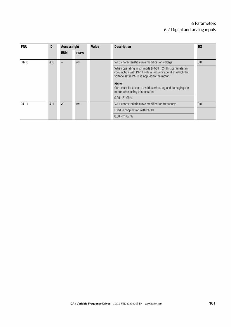
6 Parameters
6.2 Digital and analog inputs
DA1 Variable Frequency Drives 10/12 MN04020005Z-EN www.eaton.com 161
P4-10 410 – rw V/Hz characteristic curve modification voltage 0.0
When operating in V/f mode (P4-01 = 2), this parameter in conjunction with P4-11 sets a frequency point at which the voltage set in P4-11 is applied to the motor.
Note:Care must be taken to avoid overheating and damaging the motor when using this function.
0.00 - P1-09 %
P4-11 411 rw V/Hz characteristic curve modification frequency 0.0
Used in conjunction with P4-10.
0.00 - P1-07 %
PNU ID Access right Value Description DS
RUN ro/rw
6 Parameters
6.2 Digital and analog inputs
162 DA1 Variable Frequency Drives 10/12 MN04020005Z-EN www.eaton.com
6.2.11 BrakingVarious braking functions can be configured:
• DC current braking,• Generative braking (brake chopper),• mechanical braking (actuation).
The brake functions allow you to reduce undesired coasting and long coast-ing times. Mechanical braking also ensures safe operating states.
6.2.11.1 DC current brakingWith DC braking, the variable frequency drive supplies the three-phase stator winding of the three-phase motor with DC current. This generates a station-ary magnetic field which induces a voltage in the rotor while the rotor is in motion. As the electrical resistance of the rotor is very low, even small induc-tion can generate high rotor currents and thus a strong braking effect.
As the speed slows down, the frequency of the induced voltage and with it the inductive resistance drops. The resistive load becomes more effective and increases the braking effect.
→ DC current braking is not suitable for holding loads or for inter-mediate braking. Nor for intermediate braking.
NOTICE
DC current braking will cause increased motor heating.
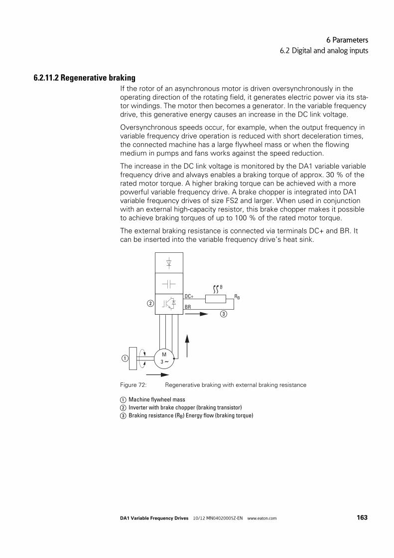
6 Parameters
6.2 Digital and analog inputs
DA1 Variable Frequency Drives 10/12 MN04020005Z-EN www.eaton.com 163
6.2.11.2 Regenerative brakingIf the rotor of an asynchronous motor is driven oversynchronously in the operating direction of the rotating field, it generates electric power via its sta-tor windings. The motor then becomes a generator. In the variable frequency drive, this generative energy causes an increase in the DC link voltage.
Oversynchronous speeds occur, for example, when the output frequency in variable frequency drive operation is reduced with short deceleration times, the connected machine has a large flywheel mass or when the flowing medium in pumps and fans works against the speed reduction.
The increase in the DC link voltage is monitored by the DA1 variable variable frequency drive and always enables a braking torque of approx. 30 % of the rated motor torque. A higher braking torque can be achieved with a more powerful variable frequency drive. A brake chopper is integrated into DA1 variable frequency drives of size FS2 and larger. When used in conjunction with an external high-capacity resistor, this brake chopper makes it possible to achieve braking torques of up to 100 % of the rated motor torque.
The external braking resistance is connected via terminals DC+ and BR. It can be inserted into the variable frequency drive’s heat sink.
Figure 72: Regenerative braking with external braking resistance
a Machine flywheel mass
b Inverter with brake chopper (braking transistor)
c Braking resistance (RB) Energy flow (braking torque)
M
RB
3 ˜①
②
③
ϑ
DC+
BR
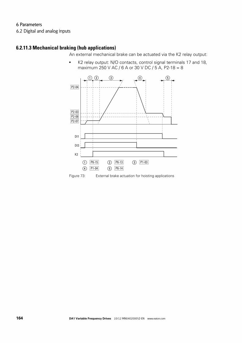
6 Parameters
6.2 Digital and analog inputs
164 DA1 Variable Frequency Drives 10/12 MN04020005Z-EN www.eaton.com
6.2.11.3 Mechanical braking (hub applications)An external mechanical brake can be actuated via the K2 relay output:
• K2 relay output: N/O contacts, control signal terminals 17 and 18,maximum 250 V AC / 6 A or 30 V DC / 5 A, P2-18 = 8
Figure 73: External brake actuation for hoisting applications
DI1
DI3
K2
P2-04
P2-08
P2-03
P2-07
① ② ③ ④ ⑤
① P6-15 ② P6-13
④ P1-04 ⑤ P6-14
③ P1-03

6 Parameters
6.2 Digital and analog inputs
DA1 Variable Frequency Drives 10/12 MN04020005Z-EN www.eaton.com 165
PNU ID Access right Value Description DS
RUN ro/rw
P1-03 103 rw Acceleration time (acc1) 5
0.1 - 600 s
P1-04 104 rw Deceleration time (dec1) 5
0.1 - 600 s
P1-05 rw Stop Function 1
0 Ramp, deceleration =Regenerative braking. Deceleration time with the value set under P1-04 (dec1).If the energy that is fed back by the motor during the dynamic braking is too high, the deceleration time has to be extended. In devices with an internal braking transistor, the excess energy can be dissipated with an external braking resistor (optional).
1 Free coasting =After the start enable (FWD/REV) is switched off or the STOP pushbutton is pressed (P1-12 and P1-13), the motor will coast uncontrolled.
2 Ramp, quick stop = regenerative braking.Deceleration time 2 with the value set under P2-25 (dec2).If the energy that is fed back by the motor during the dynamic braking is too high, the deceleration time has to be extended. In devices with an internal braking transistor, the excess energy can be dissipated with an external braking resistor (optional).
3 Free coasting, with activated braking chopper =After the start enable (FWD/REV) is switched off or the STOP pushbutton is pressed (P1-12 and P1-13), the motor will coast uncontrolled.If the energy that is fed back by the motor during the dynamic braking is too high, the deceleration time has to be extended. In devices with an internal braking transistor, the excess energy can be dissipated with an external braking resistor (optional).
P2-03 203 rw Fixed frequency FF3 / speed 3 0.0
P1-10 = 0 → -P1-02 - P1-01 → HzP1-10 > 0 → -P1-02 - P1-01 x 60 s → rpm (1/min)
0.00 Hz (P1-02) up to the maximum frequency value (P1-01).Activation via digital inputs depending on parameters P1-12 and P1-13.
P2-04 204 rw Fixed frequency FF4 / speed 4 0.0
P1-10 = 0 → -P1-02 - P1-01 → HzP1-10 > 0 → -P1-02 - P1-01 x 60 s → rpm (1/min)
0.00 Hz (P1-02) up to the maximum frequency value (P1-01).Activation via digital inputs depending on parameters P1-12 and P1-13.

6 Parameters
6.2 Digital and analog inputs
166 DA1 Variable Frequency Drives 10/12 MN04020005Z-EN www.eaton.com
P2-07 207 rw Fixed frequency FF7 / speed 7 0.0
P1-10 = 0 → -P1-02 - P1-01 → HzP1-10 > 0 → -P1-02 - P1-01 x 60 s → rpm (1/min)
0.00 Hz (P1-02) up to the maximum frequency value (P1-01).Activation via digital inputs depending on parameters P1-12 and P1-13.
P2-08 208 rw Fixed frequency FF8 / speed 8 0.0
P1-10 = 0 → -P1-02 - P1-01 → HzP1-10 > 0 → -P1-02 - P1-01 x 60 s → rpm (1/min)
0.00 Hz (P1-02) up to the maximum frequency value (P1-01).Activation via digital inputs depending on parameters P1-12 and P1-13.
P6-13 613 rw Motor brake opening time 0.2
Sets the time for which the drive will hold at the Brake Release Speed (set in P2-07 - Preset Speed 7) to allow the motor brake to release.
0.00 - 5.00 s
P6-14 614 rw Motor brake engagement delay 0.3
Sets the time for which the drive will hold at the Brake Apply Speed (set in P2-08 - Preset Speed 8) to allow the motor brake to engage. For vertical hoist applications this value should not be set below the time required for the brake to engage (brake response time, as specified by the brake manufacturer). The minimum time is 0.1 s.
0.00 - 5.00 s
P6-15 615 rw Minimum torque for brake opening 8.0
Used to define the torque level (as a percentage of the rated motor torque) that must be reached before the signal for releasing the motor brake is issued. This ensures that the motor is connected and that sufficient torque is being generated in order to prevent the load from dropping when the mechanical brake is released. The function for the torque limit is not enabled in V/Hz mode.
0.00 - 200 %
PNU ID Access right Value Description DS
RUN ro/rw
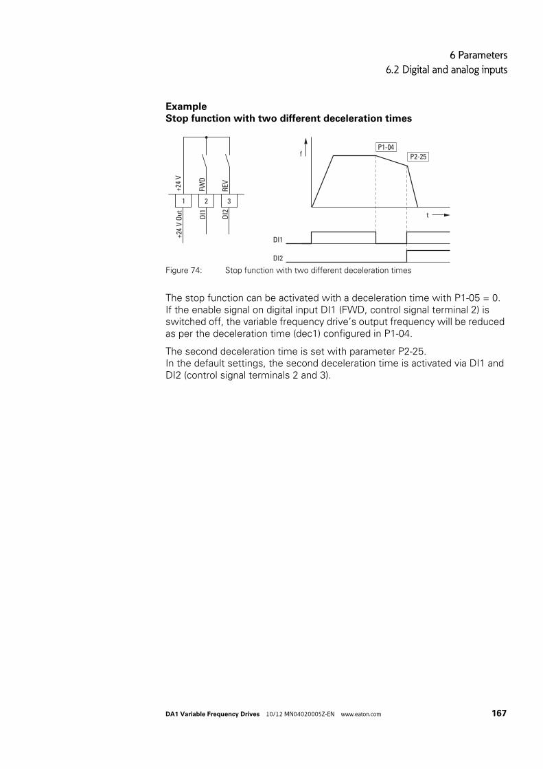
6 Parameters
6.2 Digital and analog inputs
DA1 Variable Frequency Drives 10/12 MN04020005Z-EN www.eaton.com 167
ExampleStop function with two different deceleration times
The stop function can be activated with a deceleration time with P1-05 = 0.If the enable signal on digital input DI1 (FWD, control signal terminal 2) is switched off, the variable frequency drive’s output frequency will be reduced as per the deceleration time (dec1) configured in P1-04.
The second deceleration time is set with parameter P2-25.In the default settings, the second deceleration time is activated via DI1 and DI2 (control signal terminals 2 and 3).
Figure 74: Stop function with two different deceleration times
2D
I1
DI2
3FW
D
REV+2
4 V
1
+24
V O
ut
f
t
P1-04P2-25
DI1
DI2

6 Parameters
6.3 Operational data indicator
168 DA1 Variable Frequency Drives 10/12 MN04020005Z-EN www.eaton.com
6.3 Operational data indicator
When the specified supply voltage is applied (L1/L, L2/N, L3), the 7-segment LED display will be illuminated (Power ON); the display will show “Stop“.
You can use arrow buttons and to select the operational data indicator you want (parameter number P0-…) in the “Monitor“ (P0-…) menu. You can tell the display to stop alternating between the parameter number and the display value and only show the display value instead by pressing the OK but-ton. If you want to access a different operational data indicator, press the OK button again. You can then make your selection using the and arrow buttons and confirm it with the OK button.
Example: Status displays
The status displays of the digital inputs and outputs are equivalent. They can be used to check whether an output control signal (e.g. from an external con-troller) activates the variable frequency drive’s inputs (DI1 to DI4). This pro-vides you with an easy way to check the wiring (wire breakage).
The following table shows a few examples.
Display value:
• 1 = activated = High• 0 = not activated = Low
→ The values of the operating data display cannot be changed by hand (i.e. by value entry).
PNU ID Display value Description
P0-03 11 00000 No digital input (DI1, DI2, DI3, DI4, DI5) is actuated
10000 Control signal terminal 2 actuated (DI1)
01000 Control signal terminal 3 actuated (DI2)
00100 Control signal terminal 4 actuated (DI3)
00010 Control signal terminal 6 actuated (DI4)
00001 Control signal terminal 10 actuated (DI5)
10101 Control signal terminals 2, 4 and 10 are actuated (DI2, DI3, DI5)

6 Parameters
6.4 Setpoint input (REF)
DA1 Variable Frequency Drives 10/12 MN04020005Z-EN www.eaton.com 169
6.4 Setpoint input (REF)
REF: Setpoint value definition (Reference) via the operating unit
The frequency reference value settings configured via the keypad have the same effect as the function of an electronic motor potentiometer. The value set with the and buttons will be retained even after the supply voltage is switched off.
The following table shows a good example of specifying the frequency reference value via the operating unit.
Note: The information in the table may vary depending on the setting configured for P1-13.
→ For control via the keypad, control signal terminal 1 must be connected to control signal terminal 2 in order to get an enable.
Sequence Commands Indicator Description
1 Set parameter P1-12 to 1 or 2 in order to hand over control to the keypad.
1: Operating unit (keypad FWD): one operating direction2: Operating unit (keypad FWD/REV): both operating directions
2 Connect control signal terminal 1 to control signal terminal 2 in order to get a start enable.
Press the STOP pushbutton in order to get to the setpoint input display automatically.
Use the and arrow buttons to change the setpoint value.

6 Parameters
6.4 Setpoint input (REF)
170 DA1 Variable Frequency Drives 10/12 MN04020005Z-EN www.eaton.com
3 Press the START pushbutton to start the variable frequency drive.It will then run with the acceleration time set in P1-03 all the way to the setpoint value on the keypad.
You can use the and arrow buttons to change the setpoint value in RUN mode.
4 Pressing the START pushbutton again will change the operating direction (P1-12 = 2).
Note:When the REV operating direction is in effect, the frequency will have a minus sign.
FWD
REV Minus sign for REV operating direction
5 When the STOP pushbutton is pressed, the variable frequency drive will be stopped with the deceleration time configured in P1-04.
Sequence Commands Indicator Description

7 Serial interface (Modbus RTU)
7.1 General
DA1 Variable Frequency Drives 10/12 MN04020005Z-EN www.eaton.com 171
7 Serial interface (Modbus RTU)
7.1 GeneralModbus is a centrally polled bus system in which a so-called master (PLC) controls the entire data transfer on the bus. Internode communication between the individual modules (slaves) is not possible.
Every single data transfer operation is initiated by the master with a request. Only one request can be sent on the cable at a time.Slaves are not able to initiate transfers, and are only able to respond to requests.
Two types of dialog are possible between master and slave:
• The master sends a request to a slave and waits for a response.• The master sends a request to all slaves and does not wait for a
response (broadcast).
7.1.1 Communication
Figure 75: Modbus network with DA1 variable frequency drives
The figure shows a typical setup with a host computer (master) and any number (a maximum of 63 modules) of DA1 variable frequency drives (slaves). Each variable frequency drive has a unique address on the network. Addresses are assigned individually to each DA1 variable frequency drive with the P5-01 parameter and are independent of their physical connection (position) within the network.
→ More information on Modbus can be found underwww.modbus.org.
Host computer
1
① ②
Host computer
2 63
L1/L L2/N L3
DC-
U
DC+ BR
1 2 3 4 5 6 7 8 9 10 11 12 13
14 15 16 17 18
COM
V W
L1/L L2/N L3
DC-
U
DC+ BR
1 2 3 4 5 6 7 8 9 10 11 12 13
14 15 16 17 18
COM
V W
3
L1/L L2/N L3
DC-
U
DC+ BR
1 2 3 4 5 6 7 8 9 10 11 12 13
14 15 16 17 18
COM
V W
L1/L L2/N L3
DC-
U
DC+ BR
1 2 3 4 5 6 7 8 9 10 11 12 13
14 15 16 17 18
COM
V W

7 Serial interface (Modbus RTU)
7.1 General
172 DA1 Variable Frequency Drives 10/12 MN04020005Z-EN www.eaton.com
7.1.2 Serial interfaceThe electrical connection between the master and the slaves is established with RJ45 cables. If multiple slaves are being used, they are connected in parallel by using RJ45 cables and DX-SPL-RJ45-3SL splitters.
The DA1 variable frequency drive built-in RJ45 port supports the Modbus RTU protocol and therefore allows a direct network connection without an additional interface module. The network cable must be provided at each physical end (last station) with a bus termination resistor of 120 Ω in orderto prevent signal reflections and the resulting transfer errors.
Splitter model DX-CBL-TERM includes the required resistor mentioned above.
Figure 76: RJ45 socket wiring
Pin Meaning
1 CAN -
2 CAN +
3 0 V
4 OP bus (operation bus) / external keypad / PC connection -
5 OP bus (operation bus) / external keypad / PC connection +
6 24 V DC power supply
7 RS485- Modbus RTU
8 RS485+ Modbus RTU
12345678

7 Serial interface (Modbus RTU)
7.2 Modbus parameters
DA1 Variable Frequency Drives 10/12 MN04020005Z-EN www.eaton.com 173
7.2 Modbus parameters
The following table 15 shows the Modbus parameters in the DA1 variable frequency drive.
RUN Indicates the access right during operation (FWD or REV)- = No parameter change possible,/ = Parameter change possible.
ro/rw Indicates the access right via the field busro = Read only possible,rw = Read and write possible.
Table 15: Modbus parameters
PNU ID Access right Designation Value range DS
RUN ro/rw
P5-01 501 rw Variable frequency drive slave address 0 - 63 1
P5-03 503 rw Modbus RTU Baud rate 0 = 9.6 kBit/s1 = 19.2 kBit/s2 = 38.4 kBit/s3 = 57.6 kBit/s4 = 115.2 kBit/s
4
P5-04 504 rw Modbus RTU data format – Parity type n-1 = No parity, 1 stop bitn-2 = No parity, 2 stop bits0-1 = Odd parity, 1 stop bitE-1 = Even parity, 1 stop bit
n-1
P5-05 505 rw Timeout – Communications dropout 0.00 - 5.00 s 2
P5-06 506 rw Response in the event of a communica-tions dropout
0 = Switch off and free coasting1 = Deceleration ramp, switch off2 = Deceleration ramp, no switch off3 = Fixed frequency 8
0
P5-07 507 rw Ramp via field bus 0 = Deactivated1 = activated
0
P1-12 – rw Control level 0 = Control signal terminals (I/O)1 = Keypad (KEYPAD FWD)2 = Keypad (KEYPAD FWD/REV)3 = PID control4 = Field bus (Modbus RTU, PROFIBUS etc.)5 = Slave mode6 = Field bus (CANopen)
0

7 Serial interface (Modbus RTU)
7.3 Operating mode Modbus RTU
174 DA1 Variable Frequency Drives 10/12 MN04020005Z-EN www.eaton.com
7.3 Operating mode Modbus RTU
Operating mode Modbus RTU (Remote Terminal Unit) transfers the data in binary format (faster data rate) and determines the transfer format for the data request and the data response. Each message byte that is sent contains two hexadecimal characters (0 - 9, A - F).
The data transfer between a master (PLC) and the DA1 variable frequency drive is carried out according to the following sequence:
• Master request: the master sends a Modbus frame to the variable frequency drive.
• Slave response: the variable frequency drive sends a Modbus frameas a response to the master.
Figure 77: Data exchange between master and slave
→ The variable frequency drive (slave) only sends a response if it has received a request from the master beforehand.
Start
SlaveMaster
Address (1 Byte)Function code (1 Byte)
Data (N x 1 Byte)
CRC (2 Bytes)End
StartAddress (1 Byte)
Function code (1 Byte)
Data (N x 1 Byte)
CRC (2 Bytes)End
7 Serial interface (Modbus RTU)
7.3 Operating mode Modbus RTU
DA1 Variable Frequency Drives 10/12 MN04020005Z-EN www.eaton.com 175
7.3.1 Structure of the master request
7.3.1.1 Address• The slave address (1 to 63) of the recipient variable frequency drive is
entered in the parameter P5-01. Only the variable frequency drive with this address can respond to the request.
• Address 0 is used as a so-called Broadcast (message to all bus users) from the master. In this mode, individual modules cannot be addressed and data cannot be output from the slaves.
7.3.1.2 Function codeThe function code defines the type of message. The following actions can be performed in the case of DA1 variable frequency drives:
7.3.1.3 DataThe length of the data block (data: N x 1 bytes) depends on the function code. The function code is made up of two hexadecimal values and has a range of 00 to FF. The data block contains additional information for the slave that will enable the latter to perform the operation specified by the master in the function code (this information may specify the parameters that need to be processed, for example).
7.3.1.4 Cyclic redundancy check (CRC)Frames in the Modbus RTU operating mode include a cyclic redundancy check (CRC). The CRC field is made up of two bytes that contain a binary 16-bit value. The CRC check is always run independently of the parity check for the individual characters of the telegram. The CRC result is appended to the frame by the master. While receiving the frame, the slave performs a new calculation and compares the calculated value to the actual value in the CRC field. If both values are not identical, an error is set.
Function code[hex]
Designation Description
03 Read Holding Registers Reading of the holding registers (process data, parameters, configuration) in the slave.A master request enables up to 11 registers to be read.
06 Write Single Register Writing of a holding register in the slave.With a general telegram (Broadcast) the appropriate holding registers are written in all slaves. The register is read back for comparison.

7 Serial interface (Modbus RTU)
7.3 Operating mode Modbus RTU
176 DA1 Variable Frequency Drives 10/12 MN04020005Z-EN www.eaton.com
7.3.2 Structure of the slave response
7.3.2.1 Required transfer time• The time between receiving a request from the master and the response
of the variable frequency drive is at least 3.5 characters (rest time).• Once the master has received a response from the variable frequency
drive, it must wait for at least the rest time before it can send a new request.
7.3.2.2 Normal slave response• If the master request contains a write register function (function code 06),
the variable frequency drive immediately returns the request as a response.
• If the master request contains a read register function (function code 03), the variable frequency drive returns the read data with the slave address and the function code as a response.
7.3.2.3 No slave responseIn the following cases, the variable frequency drive ignores the request and does not send a reply:
• On receiving a broadcast request.• If the request contains a transmission error.• If the slave address in the request does not match the variable frequency
drive’s address.• With a CRC or parity error.• If the time interval between the messages is less
than 3.5 characters.
→ The master must be programmed to repeat the request if it does not receive a response within a specified time.
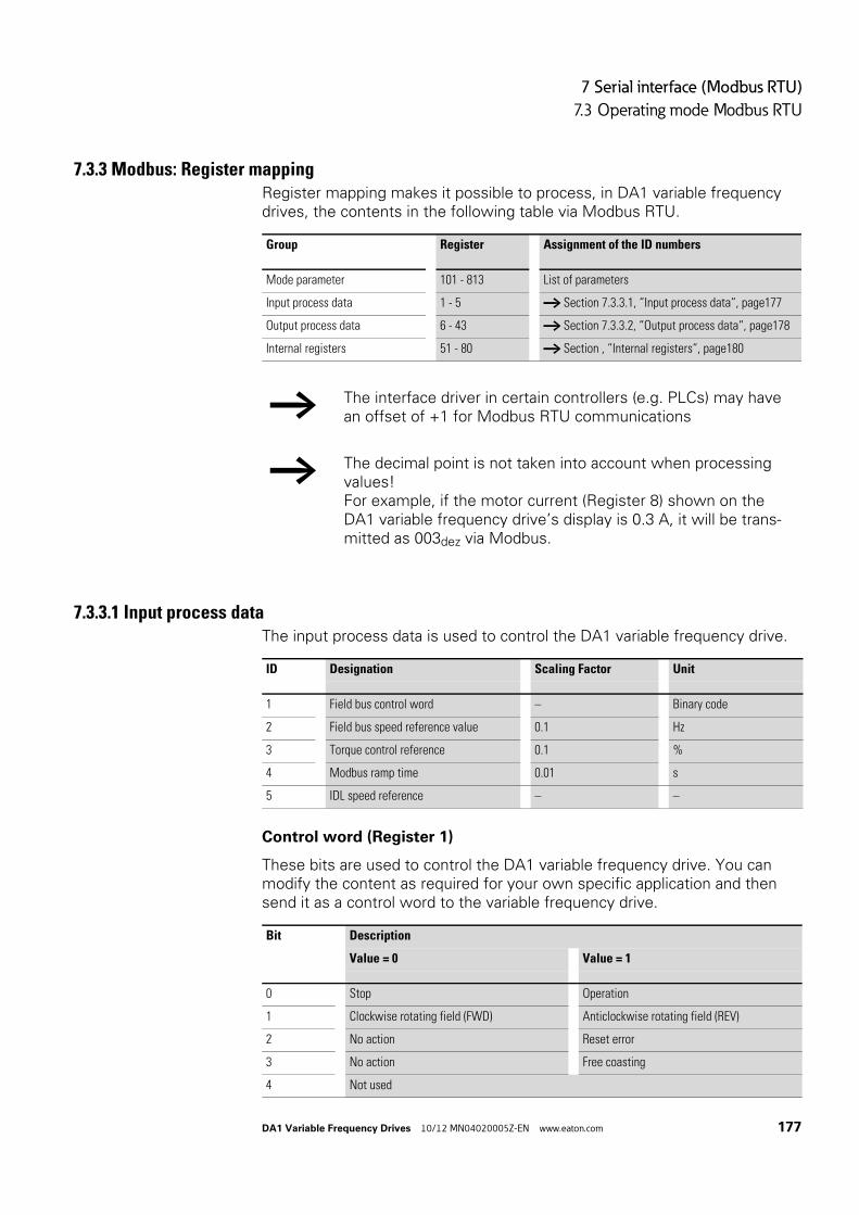
7 Serial interface (Modbus RTU)
7.3 Operating mode Modbus RTU
DA1 Variable Frequency Drives 10/12 MN04020005Z-EN www.eaton.com 177
7.3.3 Modbus: Register mappingRegister mapping makes it possible to process, in DA1 variable frequency drives, the contents in the following table via Modbus RTU.
7.3.3.1 Input process dataThe input process data is used to control the DA1 variable frequency drive.
Control word (Register 1)
These bits are used to control the DA1 variable frequency drive. You can modify the content as required for your own specific application and then send it as a control word to the variable frequency drive.
Group Register Assignment of the ID numbers
Mode parameter 101 - 813 List of parameters
Input process data 1 - 5 → Section 7.3.3.1, “Input process data“, page177
Output process data 6 - 43 → Section 7.3.3.2, “Output process data“, page178
Internal registers 51 - 80 → Section , “Internal registers“, page180
→ The interface driver in certain controllers (e.g. PLCs) may have an offset of +1 for Modbus RTU communications
→ The decimal point is not taken into account when processing values!For example, if the motor current (Register 8) shown on the DA1 variable frequency drive’s display is 0.3 A, it will be trans-mitted as 003dez via Modbus.
ID Designation Scaling Factor Unit
1 Field bus control word – Binary code
2 Field bus speed reference value 0.1 Hz
3 Torque control reference 0.1 %
4 Modbus ramp time 0.01 s
5 IDL speed reference – –
Bit Description
Value = 0 Value = 1
0 Stop Operation
1 Clockwise rotating field (FWD) Anticlockwise rotating field (REV)
2 No action Reset error
3 No action Free coasting
4 Not used

7 Serial interface (Modbus RTU)
7.3 Operating mode Modbus RTU
178 DA1 Variable Frequency Drives 10/12 MN04020005Z-EN www.eaton.com
Speed reference value (Register 2)
The permissible values fall within a range of 0 to P1-01 (max. frequency). This value is scaled with a factor of 0.1 in the application.
7.3.3.2 Output process dataThe output process data is used to monitor the variable frequency drive.
5 No action Quick stop (ramp 2)
6 No action Fixed frequency FF1
7 No action Overwrite setpoint value with 0
8 Not used Control via field bus
9 Not used
10 Not used
11 Not used
12 Not used
13 Not used
14 Not used
15 Not used
Bit Description
Value = 0 Value = 1
15 14 13 12 11 10 9 8 7 6 5 4 3 2 1 0
MSB LSB
ID Designation Scaling Factor Unit/Format
6 Status and fault word – Binary code
7 Field bus actual speed 0.1 Hz
8 Motor current 0.1 A
9 Torque 0.1 %
10 Output power 0.01 kW
11 DI status – Binary code
12 Type – WORD
13 Power 1 kW/HP
14 Voltage level 1 V
15 Software version, control part – WORD
16 Software version, power section – WORD
17 Drive ID – WORD
18 Bandwidth of channel 1 – –
19 Bandwidth of channel 2 – –
20 Value AI1 0.1 %

7 Serial interface (Modbus RTU)
7.3 Operating mode Modbus RTU
DA1 Variable Frequency Drives 10/12 MN04020005Z-EN www.eaton.com 179
21 Value AI2 0.1 %
22 Reference input speed 1 RPM
23 DC link voltage 1 V
24 Variable frequency drive temperature 1 °C
25 Inverters, serial number 4 – –
26 Inverters, serial number 3 – –
27 Inverters, serial number 2 – –
28 Inverters, serial number 1 – –
29 Status of relay output – –
30 kWh meter 0.1 kWh
31 MWh counter 0.1 MWh
32 kWh meter 0.1 kWh
33 MWh counter 0.1 MWh
34 Operating time in hours – –
35 Operating time in minutes/seconds – –
36 Operating time since last enable, in hours – –
37 Operating time since last enable,in minutes/seconds
– –
38 reserved – –
39 Room temperature – –
40 IDL speed reference – –
41 Torque reference value – –
42 Digital output reference value – –
43 P0-80 – –
ID Designation Scaling Factor Unit/Format

7 Serial interface (Modbus RTU)
7.3 Operating mode Modbus RTU
180 DA1 Variable Frequency Drives 10/12 MN04020005Z-EN www.eaton.com
Internal registers
51 User register 1 – –
52 User register 2 – –
53 User register 3 – –
54 User register 4 – –
55 User register 5 – –
56 User register 6 – –
57 User register 7 – –
58 User register 8 – –
59 User register 9 – –
60 User register 10 – –
61 User register 11 – –
62 User register 12 – –
63 User register 13 – –
64 User register 14 – –
65 User register 15 – –
66 Analog output 1 – –
67 Analog output 2 – –
68 reserved – –
69 reserved – –
70 Relay output 1 – –
71 Relay output 2 – –
72 Relay output 3 – –
73 Relay output 4 – –
74 Relay output 5 – –
75 User scaling user interface – –
76 Number of decimals on the user interface – –
77 User speed reference value – –
78 User torque reference value – –
79 User ramp time – –
80 Bandwidth indexes 1, 2 – –

7 Serial interface (Modbus RTU)
7.3 Operating mode Modbus RTU
DA1 Variable Frequency Drives 10/12 MN04020005Z-EN www.eaton.com 181
7.3.3.3 Status and fault word (Register 6)Device status and error message information is provided in the status word (bit 0 to bit 7) and error word (bit 8 to bit 15).
Status word
Fault word
15 14 13 12 11 10 9 8 7 6 5 4 3 2 1 0
MSB LSB
Fault word Status word
Bit Description
Value = 0 Value = 1
0 Drive not ready Ready for operation (READY)
1 Stop Running operation message (RUN)
2 Clockwise rotating field (FWD) Anticlockwise rotating field (REV)
3 no error Fault detected (FAULT)
4 Acceleration ramp Frequency actual value equals setpoint value definition
5 – Zero speed
6 Speed control deactivated Speed control activated
7 Not used
Failure code[hex]
Value shown on display
Meaning
00 no-fit Stop, ready for operation
01 OI-b Overcurrent brake chopper
02 O-br Braking resistance overload
03 O-l • Overcurrent at variable frequency drive output• Motor overload• Excessively high temperature on variable frequency drive (heat
sink)
04 I.t-trp Motor, thermal overload
05 SAFE -1 Short-circuit at safety circuit input
06 O Volts Overvoltage (DC link)
07 U Volts Undervoltage (DC link)
08 O-t Overtemperature (heat sink)
09 U-t Undertemperature (heat sink)
0A P-def Default settings, parameters have been loaded
C0 E-trip External error message
0C SC-ObS Error, Optibus
0D FLt-dc Excessively large voltage waves in DC link
0E P-LOSS Phase failure (mains side)
0F h O-I Overcurrent at variable frequency drive output

7 Serial interface (Modbus RTU)
7.3 Operating mode Modbus RTU
182 DA1 Variable Frequency Drives 10/12 MN04020005Z-EN www.eaton.com
10 th-Flt Thermistor fault, internal (heat sink)
11 dAtA-F EEPROM checksum fault
12 4-20F Analog input:• Out-of-range value• Wire breakage (4 mA monitoring)
13 dAtA- E Error in internal memory
14 U-dEF User-definable factory parameters have been loaded
15 F-Ptc Excessively high temperature, motor PTC
16 FAN-F Fault, internal fan
17 O-hEAt Excessively high ambient temperature
18 O-torq Maximum torque limit exceeded
19 U-torq Output torque too low
1 A Out-F Fault at variable frequency drive output
1D SAFE-2 Short-circuit at safety circuit input
1D Enc-01 Encoder, communication lost
1F Enc-02 Encoder, speed error
20 Enc-03 Encoder, wrong PPRs set
21 Enc-04 Encoder, channel A fault
22 Enc-05 Encoder, channel B fault
23 Enc-06 Encoder, channel A and B fault
24 Enc-07 Encoder, RS485 data channel error
25 Enc-08 Encoder, IO communication lost
26 Enc-09 Encoder, incorrect type
27 Enc-10 Encoder
28 AtF-01 Motor stator resistance fluctuating between phases
29 AtF-02 The motor's stator resistance is too high
2B AtF-03 Motor inductance too low
C2 AtF-04 Motor inductance too high
2C AtF-05 The motor parameters do not match the motor
32 SC-FO1 Fault: Modbus communication loss error
33 SC-F02 Fault: CANopen communication loss error
34 SC-F03 Communications with field bus module disconnected
35 SC-F04 Loss of I/O card communications
3C OF-01 Connection to add-on card lost
3D OF-02 Add-on card in unknown state
46 PLC-01 Unsupported PLC function
47 PLC-02 PLC program too big
48 PLC-03 Division by 0
49 PLC-04 Lower limit is higher than upper limit
Failure code[hex]
Value shown on display
Meaning

7 Serial interface (Modbus RTU)
7.3 Operating mode Modbus RTU
DA1 Variable Frequency Drives 10/12 MN04020005Z-EN www.eaton.com 183
7.3.3.4 Actual speed (Register 7)The variable frequency drive’s actual speed falls within a value range of 0 to P1-01 (max. frequency). This value is scaled with a factor of 0.1 in the appli-cation.
Current (ID 8)
The current is specified with one decimal place.
Example: 34 ≙ 3.4 A.
Torque (ID 9)
The motor torque is specified with one decimal place.
Example: 1000 ≙ 100.0 %
Output power (ID 10)
The output power is specified in kW with one decimal place.
Example: 53 ≙ 5.3 kW
Digital inputs (ID 11)
This value indicates the digital inputs’ state. The lowest bit indicates the state of DI 1.
Type (ID 12)
The value indicates the variable frequency drive’s part no.
15 14 13 12 11 10 9 8 7 6 5 4 3 2 1 0
MSB LSB
x x x x hex Explanation
Power (see table 17)
Input and output phases and default settings
(country-specific, see table 16)
Voltage range
0 = 115 V
1 = 230 V
2 = 230 V
3 = 400 V
4 = 460 V
5 = 525 V
6 = 575 V
Size (example: 2 corresponding FS2)

7 Serial interface (Modbus RTU)
7.3 Operating mode Modbus RTU
184 DA1 Variable Frequency Drives 10/12 MN04020005Z-EN www.eaton.com
Table 16: Input and output phases
Table 17: Assigned ratings
Rated outputs (ID 13)
Indicates the device's output with two decimal places. The unit is defined in register 12.
Example: 75 ≙ 0.75
Voltage (ID 14)
Specifies the device’s specified input voltage.
Example: 230 ≙ 230 V
Control part software version (ID 15)
Specifies the software version of the control section with two decimal places.
Power section software version (ID 16)
Specifies the software version of the power section with two decimal places.
Value Country-specific default settings
Number of phaseson mains side
Number of phaseson motor side
0 kW 3 3
1 HP 3 3
2 kW 3 1
3 HP 3 1
4 kW 1 3
5 HP 1 3
6 kW 1 1
7 HP 1 1
0 1 2 3 4 5 6 7
FS2 kW 0.75 1.5 2.2 0.75 1.5 2.2 4 –
HP 1 2 3 1 2 3 5 –
FS3 kW 3 4 5.5 5.5 7.5 11 – –
HP 4 5 7.5 7.5 10 15 – –
FS4 kW 7.5 11 15 18.5 22 – – –
HP 10 15 20 25 30 – – –
FS5 kW 15 18.5 22 30 37 45 – –
HP 20 25 30 40 50 60 – –
FS6 kW 22 30 37 45 45 55 75 90
HP 30 40 50 60 60 75 12 15
FS7 kW 55 75 90 110 132 160 – –
HP 75 100 125 175 200 250 – –

7 Serial interface (Modbus RTU)
7.3 Operating mode Modbus RTU
DA1 Variable Frequency Drives 10/12 MN04020005Z-EN www.eaton.com 185
Variable frequency drive recognition (ID 17)
The device’s unique serial number.
Analog input signal (ID 20, ID 21)
Indicates the current value of the analog input with one decimal place.
Speed reference input (ID 22)
Indicates the difference between the setpoint and the process value.
7.3.4 Explanation of function code
7.3.4.1 Function code 03hex: Reading of holding registersThis function reads the content of a number of consecutive holding registers (specified register addresses).
Example:
Reading the status and fault word (ID 6) of the DA1 variable frequency drive with slave address 1.
Master request: 01 03 0005 0001 140Bhex
Slave response: 01 03 02 0000 B844hex
hex Name
01 Station address
03 Function code (reading of holding registers)
0005 5dez: The ID is 6, since the motor controller has an offset of +1.
0001 Total number of requested registers
C940 CRC
hex Name
01 Station address
03 Function code (reading of holding registers)
02 Number of consecutive data bytes (1 register = 2 byte)
0000 Content (2 byte) for register 6: 0
B844 CRC

7 Serial interface (Modbus RTU)
7.3 Operating mode Modbus RTU
186 DA1 Variable Frequency Drives 10/12 MN04020005Z-EN www.eaton.com
7.3.4.2 Function code 06hex: Writing a holding registerThis function writes data to a holding register.
Example
Writing of the control word (ID 1) of a DA1 variable frequency drive with the slave address 1.
Master request: 01 06 0000 0001 480Ahex
Slave response: 01 06 0000 0001 480hex
The slave response is a copy of the master request if it is a normal response.
hex Name
01 Station address
06 Function code (writing a holding register)
0000 0: The ID of the register for the writing operation is 1, since the master controller has an offset of +1.
0001 Content (2 byte) for register 0000 0000 0000 001bin → RUN
480A CRC
hex Name
01 Station address
06 Function code (here: writing a holding register)
0000 1: The ID of the register for the writing operation is 1, since the master controller has an offset of +1.
0001 Content (2 byte) for register 0000 0000 0000 001bin → RUN
480A CRC
→ Function code 06hex can be used for a broadcast.

8 CANopen
8.1 Data Types
DA1 Variable Frequency Drives 10/12 MN04020005Z-EN www.eaton.com 187
8 CANopen
A thorough knowledge of the CANopen field bus and the programming of a CANopen master is required in this chapter. In addition, readers must be familiar with how to use the DA1 variable frequency drive.
References
[1] CANopen – Application Layer and Communication Profile
CiA Draft Standard DS301, Version 4.02, February, 13, 2002
8.1 Data TypesCANopen has specifications for its own data types. The data types listed in the following table are used for the DA1 variable frequency drive’s CANopen protocol handler.
Table 18: CANopen data types
The following abbreviations are used throughout this chapter:
Name Description Range
Minimum Maximum
UNSIGNED8 8-bit unsigned integer (b7 to b0) 0 255
UNSIGNED16 16-bit unsigned integer (b15 to b0) 0 65535
UNSIGNED32 32-bit unsigned integer (b31 to b0) 0 4294967295
INTEGER8 8-bit signed integer (b7 to b0) –128 127
INTEGER16 16-bit signed integer (b15 to b0) –32768 32767
INTEGER32 32-bit signed integer (b31 to b0) –2147483648 2147483647
RECORD Data structure with fixed number of any types – –
CAL CAN Application Layer
CAL CAN Application Layer
CAN Controller Area Network
COB ID Communication Object Identifier
CONST Constant variable (read access only)
DEC Decimal (base-10 numeral system)
EDS Electronic Data Sheets
EMCY Emergency Object
HEX Hexadecimal (base-16 numeral system)
ID Identifier
LSS Layer Setting Service
NMT Network Management
PC Personal Computer
PDO Process Data Object
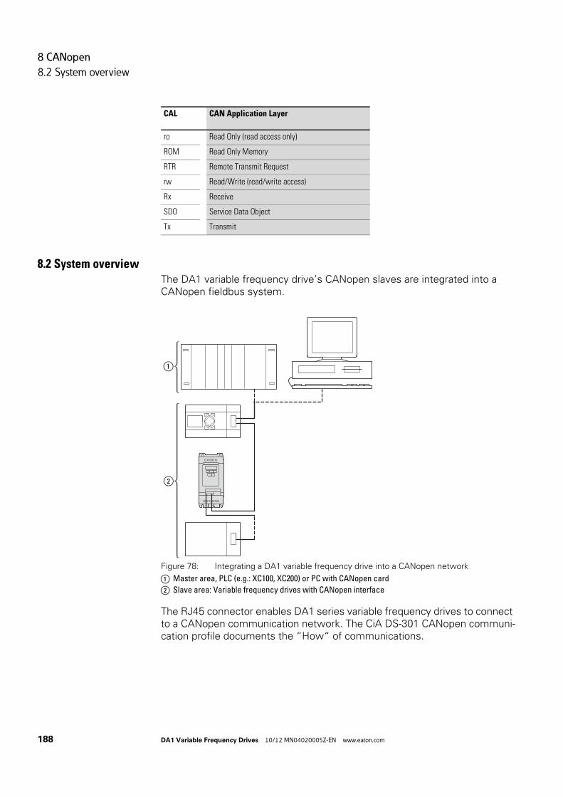
8 CANopen
8.2 System overview
188 DA1 Variable Frequency Drives 10/12 MN04020005Z-EN www.eaton.com
8.2 System overviewThe DA1 variable frequency drive’s CANopen slaves are integrated into a CANopen fieldbus system.
Figure 78: Integrating a DA1 variable frequency drive into a CANopen network
a Master area, PLC (e.g.: XC100, XC200) or PC with CANopen card
b Slave area: Variable frequency drives with CANopen interface
The RJ45 connector enables DA1 series variable frequency drives to connect to a CANopen communication network. The CiA DS-301 CANopen communi-cation profile documents the “How“ of communications.
ro Read Only (read access only)
ROM Read Only Memory
RTR Remote Transmit Request
rw Read/Write (read/write access)
Rx Receive
SDO Service Data Object
Tx Transmit
CAL CAN Application Layer
①
②

8 CANopen
8.2 System overview
DA1 Variable Frequency Drives 10/12 MN04020005Z-EN www.eaton.com 189
The CANopen communications protocol draws a distinction between pro-cess data objects (PDOs) and service data objects (SDOs).The variable frequency drive is controlled with fast, cyclic process data (PDOs). The process data channel can be used not only to specify the speed setpoint, but also to trigger various drive functions, such as enables, operat-ing directions, and resets. At the same time, it can also be used to read actual values, such as the actual speed, current, and device status, from the variable frequency drive. As a general rule, the variable frequency drive’s parameters are configured using SDOs. The parameter data channel makes it possible to store all application-related drive parameters in the higher-level automation system and transfer them to the variable frequency drive if nec-essary. All of the variable frequency drive’s parameters can be transferred with CANopen by using the appropriate SDO/PDO selection.
Table 19: Technical Data
Size Value
Communication profile DS-301 V4.02
Bus addresses 1 - 63
Data transfer rate 125 kBit/s - 1 MBit/s
Total distance (depending on the baud rate /the repeater)
• up to 500 m at 125 kBit/s• up to 300 m at 1 MBit/s
Transmission medium Screened, twisted-pair cable
Bus termination resistor 120 Ω, suitable for separate mounting
Number of SDOs 1 server, 0 clients
Number of PDOs 2 Rx-PDO2 Tx-PDO
Note:Only one will be enabled in the default settings.
PDO mapping variable
Terminal types Plug-in RJ45 socket

8 CANopen
8.2 System overview
190 DA1 Variable Frequency Drives 10/12 MN04020005Z-EN www.eaton.com
8.2.1 Bus termination resistorsThe first and last module of a CANopen network must be terminated by means of a 120 Ω bus termination resistor. This device is interconnected between the CAN_H and CAN_L terminals.Splitter DX-CBL-TERM1 ② can be used for this purpose.
Figure 79: Bus termination resistors
8.2.2 Baud rateThe baud rate is set in parameter P5-02. It must be set to the same value for all communication modules on the CANopen bus.
8.2.3 Set CANopen station addressEvery CANopen module needs a unique address (node ID) within the CANo-pen structure. All node IDs must be unique within the entire bus structure.A maximum of 127 addresses (1 to 127) can be assigned within a CANopen structure. Parameter P5-01 is used to configure the CANopen address in DA1 variable frequency drives.
8.2.4 Parameters that need to be configured
12
CAN_LCAN_H
345678
① ① ②
PNU ID Access right Designation Value range DS Value that must be set
RUN ro/rw
P1-12 112 – rw Control level 0 = Control terminals (I/O)1 = Keypad (KEYPAD FWD)2 = Keypad (KEYPAD FWD / REV)3 = PID control4 = Field bus system (Modbus RTU, PROFIBUS etc.)5 = Slave mode6 = Field bus (CANopen)
0 6
P5-01 501 rw Variable frequency drive slave address
0 - 63 1 1 - 63
P5-02 502 rw CANopen baud rate 0 = 125 kBit/s1 = 250 kBit/s2 = 500 kBit/s3 = 1000 kBit/s
500 0 - 3

8 CANopen
8.3 Object list
DA1 Variable Frequency Drives 10/12 MN04020005Z-EN www.eaton.com 191
8.3 Object list
8.3.1 EDS fileThe DC1 variable frequency drive can be integrated into a CANopen structure with the help of a standardized EDS (Electronic Data Sheet) file. EDS describes the functionality of a CANopen device in a machine-readable for-mat. EDS files list all objects, the supported baud rates, the manufacturer, and other information as well.
The latest version of the EDS file is included in the CD-ROM enclosed with every variable frequency drive.
It can also be downloaded from Eaton’s website at:
http://www.eaton.com/moeller → Support
The object dictionary contains all the objects corresponding to a CANopen module. Objects are used to map a device's functionality/parameters.
They are accessed with SDOs or PDOs. As per the corresponding specifica-tion, the object dictionary is subdivided into the following ranges:
Table 20: Object dictionary ranges
The object dictionary for the DA1 variable frequency drive contains the entries described below.
Range Description
0000hex - 1FFFhex Communication-specific objects (from DS-301)
2000hex - 5FFFhex Manufacturer-specific objects (the variable frequency drive’s parameters)

8 CANopen
8.3 Object list
192 DA1 Variable Frequency Drives 10/12 MN04020005Z-EN www.eaton.com
8.3.2 Communication-specific objectsA detailed description of the communication parameters is provided in the CiA specification [1] Section 9.6.3.
Objects 1000hex, 1001hex, and 1018hex are required for all CANopen devices; all other objects are optional. The DA1 variable frequency drive supports the objects listed in the following tables.
Index[hex]
Subindex[hex]
Objectname Data type Access right
DS Meaning
1000 00 Device Type UNSIGNED32 ro 0 Variable frequency drive – CANopen device
1001 00 Error Register UNSIGNED8 ro – Error indication:00hex = No error
1002 00 Manufacturer Status Register UNSIGNED16 ro 00 Emergency object fault log
1005 00 COB-ID SYNC Message UNSIGNED32 rw 80 COB-ID of the SYNC object, device consumes the SYNC message
1008 00 Manufacturer Device Name STRING ro DA1 The variable frequency drive's device name: DA1
1009 00 Manufacturer Hardware Version STRING ro 1.11(Example)
Hardware version of the module
100A 00 Manufacturer Software Version STRING ro 1.00(Example)
Software version of the module
100C 00 Guard Time UNSIGNED16 rw 0000hex Resolution in 1 ms
Monitoring time in milliseconds
100D 00 Life Time Factor UNSIGNED8 rw 00hex Multiplier for the Guard Time, the result is equivalent to the maximum interval between the transfer of two Guarding message frames
1014 00 COB-ID EMCY Message UNSIGNED32 rw 00000080 + Node ID
CAN identifier of the emergency message
1018 00 Identity Object UNSIGNED8 ro 04 General device information
01 Vendor ID UNSIGNED32 ro 000001C7 Manufacturer:Eaton Industries GmbH
02 Product Code UNSIGNED32 ro 0 Product Number
03 Revision Number UNSIGNED32 ro 1.01(Example)
Version
04 Serial Number UNSIGNED32 ro 00000001(Example)
Serial number

8 CANopen
8.3 Object list
DA1 Variable Frequency Drives 10/12 MN04020005Z-EN www.eaton.com 193
8.3.3 Server SDO Parameter
The DA1 variable frequency drive supports two receive PDOs (receive PDO communication parameters 1400hex and 1401hex).
Objects 1600hex and 1601hex contain the mapping parameters for the Rx PDOs.
Index[hex]
Subindex[hex]
Objectname Data type Access right
DS Meaning
1200 00 Number of Entries UNSIGNED8 ro 02 Number of inputs
01 COB-ID Client a Server (rx) UNSIGNED32 ro 00000600 + Node ID
COB-ID of the RxSDO. The ID is derived from the Predefined Connection Set.
02 COB-ID Server a Client (tx) UNSIGNED32 ro 00000580 + Node ID
COB-ID of the TxSDO. The ID is derived from the Predefined Connection Set.
Index[hex]
Subindex[hex]
Objectname Data type Access right
DS Meaning
14001401
1st Receive PDO Parameter 2nd Receive PDO Parameter
RECORD ro 03 Number of valid subindexes
00 Number of Entries UNSIGNED8 ro 02 Maximum number of entries
01 PDO COB-ID UNSIGNED32 rw 4000002 00400000300+ Node ID
COB-ID of 1st Rx PDOCOB-ID of 2nd Rx PDO
02 Transmission Type UNSIGNED8 rw 254 PDO transmission type: asyn-chronous
1600 00 Number of Mapped Application Objects
UNSIGNED8 rw 04 Highest subindex used
01 1st Mapping Object UNSIGNED32 rw 20000010
02 2nd Mapping Object UNSIGNED32 rw 20000010
03 3rd Mapping Object UNSIGNED32 rw 20020010
04 4th Mapping Object UNSIGNED32 rw 20020010
1601 00 Number of Mapped Application Objects
UNSIGNED8 rw 4 Highest subindex used
01 1st Mapping Object UNSIGNED32 rw 00060010
02 2nd Mapping Object UNSIGNED32 rw 00060010
03 3rd Mapping Object UNSIGNED32 rw 00060010
04 4th Mapping Object UNSIGNED32 rw 00060010

8 CANopen
8.3 Object list
194 DA1 Variable Frequency Drives 10/12 MN04020005Z-EN www.eaton.com
DA1 variable frequency drive supports two transmit PDOs (transmit PDO communication parameters 1800hex and 1801hex).
Objects 1A00hex and 1A01hex contain the mapping parameters for the Tx PDOs.
Index[hex]
Subindex[hex]
Objectname Data type Access right
DS Meaning
18001801
1st Transmit PDO Parameter 2nd Transmit PDO Parameter
RECORD ro 04 Number of valid subindexes
00 Number of Entries UNSIGNED8 ro 03 Number of entries
01 PDO COB-ID UNSIGNED32 rw 4000018040000280+ Node ID
COB-ID of 1st Tx PDOCOB-ID of 2nd Tx PDO
02 Transmission Type UNSIGNED8 rw 254 PDO transmission type: asyn-chronous
03 Inhibit time (100 μs) UNSIGNED16 ro 0
1A00 1st Transmit PDO Mapping RECORD applies for Tx PDO 1
00 Number of Mapped Application Objects
UNSIGNED8 rw 4 Highest subindex used
01 1st Mapping Object UNSIGNED32 rw 200A0010
02 2nd Mapping Object UNSIGNED32 rw 200B0010
03 3rd Mapping Object UNSIGNED32 rw 200D0010
04 4th Mapping Object UNSIGNED32 rw 200E0010
1A01 2nd Transmit PDO Mapping RECORD applies for Tx PDO 2
00 Number of Mapped Application Objects
UNSIGNED8 rw 4 Highest subindex used
01 1st Mapping Object UNSIGNED32 rw 200F0010
02 2nd Mapping Object UNSIGNED32 rw 20100010
03 3rd Mapping Object UNSIGNED32 rw 20110010
04 4th Mapping Object UNSIGNED32 rw 200C0010

8 CANopen
8.3 Object list
DA1 Variable Frequency Drives 10/12 MN04020005Z-EN www.eaton.com 195
8.3.4 Manufacturer-specific objectsIn addition to communication-specific objects, manufacturer-specific objects are also defined in the object dictionary. These objects fall within the range between index 2000hex and index 23E9hex in the DA1 variable frequency drive's object dictionary.
Table 21: Manufacturer-specific objects
Index[hex]
Property Name Data type Access right
Description
2000 Control command register UNSIGNED16 rw Control word
2001 Speed reference INTEGER16 rw Frequency reference value
2002 Torque reference Integer16 rw Torque control reference
2003 User ramp reference UNSIGNED16 rw User ramp time
2004 Speed ref (internal) INTEGER16 rw IDL speed reference
200A Drive status register UNSIGNED16 ro Status word
C200 Motor speed Hz UNSIGNED16 ro Actual value in Hertz (Hz)
200C Motor speed (internal) UNSIGNED16 ro IDL actual speed
200D Motor current UNSIGNED16 ro Motor current
200E Motor torque INTEGER16 ro Torque
200F Motor power UNSIGNED16 ro Power in kW
2010 Drive temperature INTEGER16 ro Variable frequency drive temperature
2011 DC bus value UNSIGNED16 ro DC link voltage
2012 Digital input status UNSIGNED16 ro State of digital inputs
2013 Analog input 1 (%) UNSIGNED16 ro Analog input 1 in %
2014 Analog input 2 (%) UNSIGNED16 ro Analog input 2 in %
2015 Analog input 1 UNSIGNED16 ro Analog input 1
2016 Analog input 2 UNSIGNED16 ro Analog input 2
2017 Relay output 1 UNSIGNED16 ro Relay output 1
2018 Relay output 2 UNSIGNED16 ro Relay output 2
2019 Relay output 3 UNSIGNED16 ro Relay output 3
201A Relay output 4 UNSIGNED16 ro Relay output 4
C201 Relay output 5 UNSIGNED16 ro Relay output 5
201C Scope channel 1 UNSIGNED16 ro Scope channel 1
201D Scope channel 2 UNSIGNED16 ro Scope channel 2
201E Scope channel 3 UNSIGNED16 ro Scope channel 3
201F Scope channel 4 UNSIGNED16 ro Scope channel 4
2020 User data 1 UNSIGNED16 rw User data 1
2021 User data 2 UNSIGNED16 rw User data 2
2022 User data 3 UNSIGNED16 rw User data 3
2023 User data 4 UNSIGNED16 rw User data 4
2024 User data 5 UNSIGNED16 rw User data 5

8 CANopen
8.3 Object list
196 DA1 Variable Frequency Drives 10/12 MN04020005Z-EN www.eaton.com
2025 User data 6 UNSIGNED16 rw User data 6
2026 User data 7 UNSIGNED16 rw User data 7
2027 User data 8 UNSIGNED16 rw User data 8
2028 User data 9 UNSIGNED16 rw User data 9
2029 User data 10 UNSIGNED16 rw User data 10
202A User data 11 UNSIGNED16 rw User data 11
C202 User data 12 UNSIGNED16 rw User data 12
202C User data 13 UNSIGNED16 rw User data 13
202D User data 14 UNSIGNED16 rw User data 14
202E User data 15 UNSIGNED16 rw User data 15
202F User analog output 1 UNSIGNED16 rw User, analog output 1
2030 User analog output 2 UNSIGNED16 rw User, analog output 2
2033 User relay output 1 UNSIGNED16 rw User, relay output 1
2034 User relay output 2 UNSIGNED16 rw User, relay output 2
2035 User relay output 3 UNSIGNED16 rw User, relay output 3
2036 User relay output 4 UNSIGNED16 rw User, relay output 4
2037 User relay output 5 UNSIGNED16 rw User, relay output 5
203A Kilowatt hours UNSIGNED16 ro Operating time in kW
C203 Megawatt hours UNSIGNED16 ro Operating time in MW
203C KWh meter UNSIGNED16 ro Total operating time in kW
203D MWh meter UNSIGNED16 ro Total operating time in MW
203E Total run hours UNSIGNED16 ro Operating time in hours
203F Total run minute/second UNSIGNED16 ro Operating time inminutes/seconds
2040 Current run hours UNSIGNED16 ro Current operating time in hours
2041 Current run minute/second UNSIGNED16 ro Current operating time in minutes/seconds
2042 Time to next service UNSIGNED16 ro Time to next service
2043 Room temperaure UNSIGNED16 ro Room temperature
2044 Speed controller reference UNSIGNED16 ro
2045 Torque controller reference UNSIGNED16 ro
2046 Digital pot speed reference UNSIGNED16 ro
2065 P1-01 rw Parameter of P1 group
To …
2072 P1-14
20C9 P2-01 rw Parameter of P2 group
To …
20F0 P2-40
Index[hex]
Property Name Data type Access right
Description
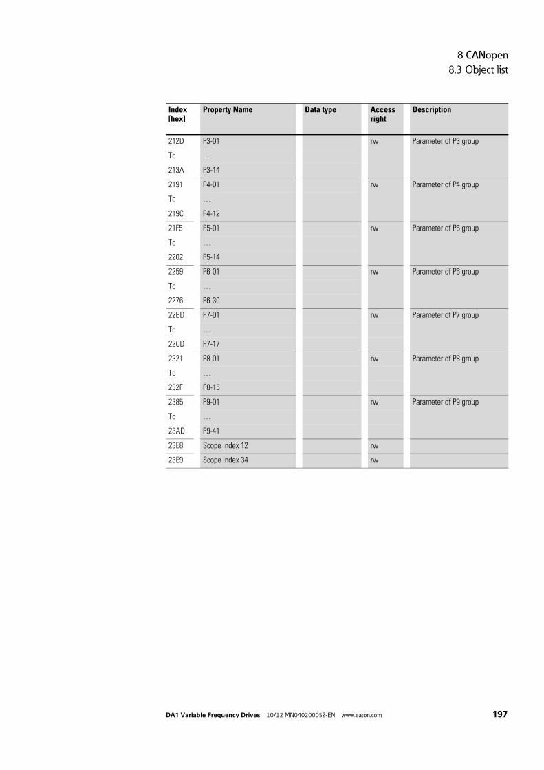
8 CANopen
8.3 Object list
DA1 Variable Frequency Drives 10/12 MN04020005Z-EN www.eaton.com 197
212D P3-01 rw Parameter of P3 group
To …
213A P3-14
2191 P4-01 rw Parameter of P4 group
To …
219C P4-12
21F5 P5-01 rw Parameter of P5 group
To …
2202 P5-14
2259 P6-01 rw Parameter of P6 group
To …
2276 P6-30
22BD P7-01 rw Parameter of P7 group
To …
22CD P7-17
2321 P8-01 rw Parameter of P8 group
To …
232F P8-15
2385 P9-01 rw Parameter of P9 group
To …
23AD P9-41
23E8 Scope index 12 rw
23E9 Scope index 34 rw
Index[hex]
Property Name Data type Access right
Description
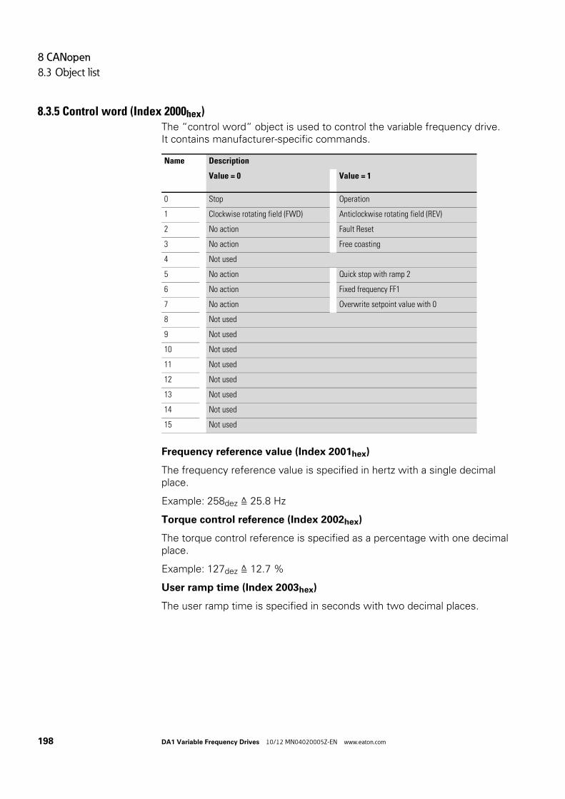
8 CANopen
8.3 Object list
198 DA1 Variable Frequency Drives 10/12 MN04020005Z-EN www.eaton.com
8.3.5 Control word (Index 2000hex)The “control word“ object is used to control the variable frequency drive.It contains manufacturer-specific commands.
Frequency reference value (Index 2001hex)
The frequency reference value is specified in hertz with a single decimal place.
Example: 258dez ≙ 25.8 Hz
Torque control reference (Index 2002hex)
The torque control reference is specified as a percentage with one decimal place.
Example: 127dez ≙ 12.7 %
User ramp time (Index 2003hex)
The user ramp time is specified in seconds with two decimal places.
Name Description
Value = 0 Value = 1
0 Stop Operation
1 Clockwise rotating field (FWD) Anticlockwise rotating field (REV)
2 No action Fault Reset
3 No action Free coasting
4 Not used
5 No action Quick stop with ramp 2
6 No action Fixed frequency FF1
7 No action Overwrite setpoint value with 0
8 Not used
9 Not used
10 Not used
11 Not used
12 Not used
13 Not used
14 Not used
15 Not used

8 CANopen
8.3 Object list
DA1 Variable Frequency Drives 10/12 MN04020005Z-EN www.eaton.com 199
Status word (Index 200Ahex)
Information regarding the variable frequency drive’s device status (Bit 0 to Bit 7) and error messages (Bit 8 to Bit 15) is specified in the status word.
15 14 13 12 11 10 9 8 7 6 5 4 3 2 1 0
MSB LSB
Error messages Status word
Name Description
Value = 0 Value = 1
0 Drive not ready READY
1 Stop Running operation message (RUN)
2 Clockwise rotating field (FWD) Anticlockwise rotating field (REV)
3 No error Fault detected (FAULT)
4 Acceleration ramp Frequency actual value equals setpoint value definition
5 – Zero speed
6 Speed control deactivated Speed control activated
7 Not used
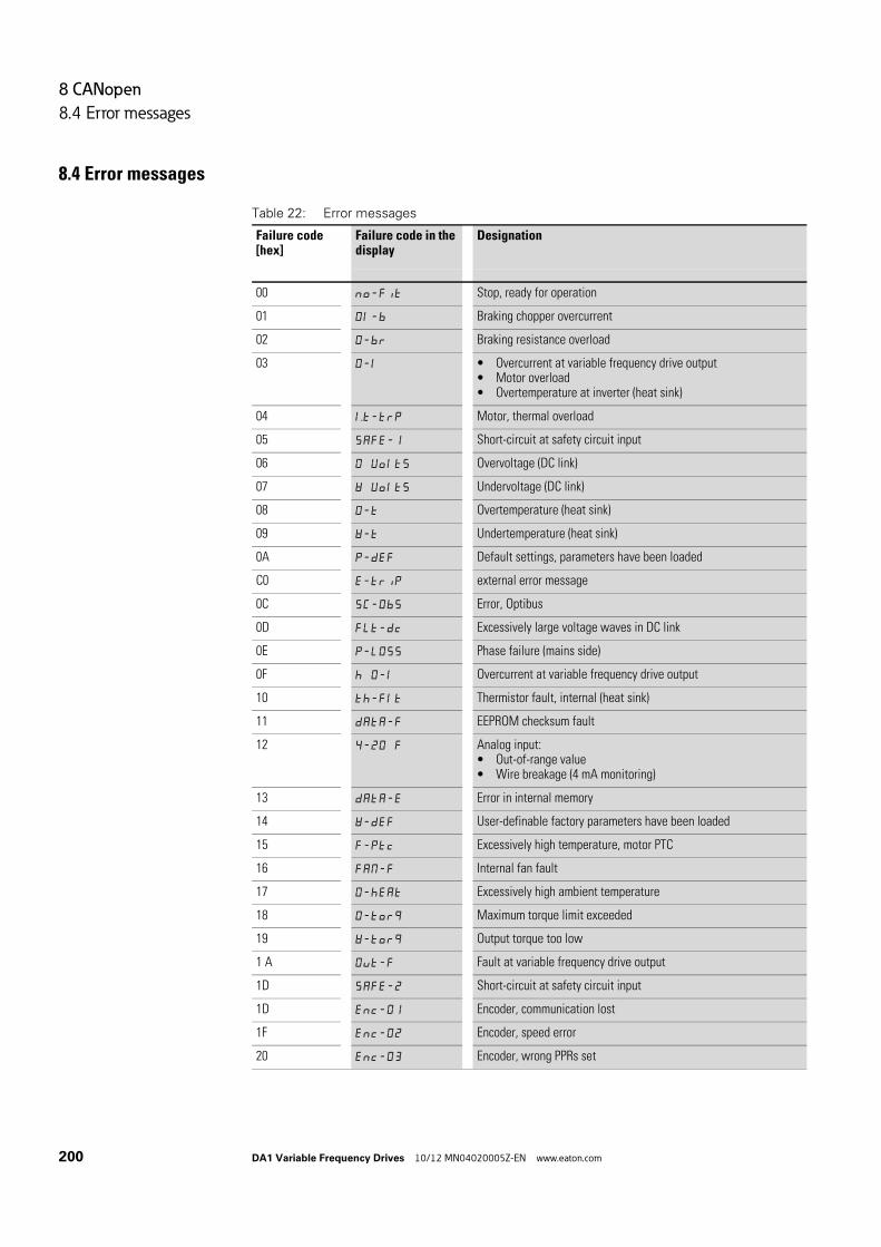
8 CANopen
8.4 Error messages
200 DA1 Variable Frequency Drives 10/12 MN04020005Z-EN www.eaton.com
8.4 Error messages
Table 22: Error messages
Failure code[hex]
Failure code in the display
Designation
00 no-fit Stop, ready for operation
01 OI-b Braking chopper overcurrent
02 O-br Braking resistance overload
03 O-l • Overcurrent at variable frequency drive output• Motor overload• Overtemperature at inverter (heat sink)
04 I.t-trp Motor, thermal overload
05 SAFE-1 Short-circuit at safety circuit input
06 O Volts Overvoltage (DC link)
07 U Volts Undervoltage (DC link)
08 O-t Overtemperature (heat sink)
09 U-t Undertemperature (heat sink)
0A P-dEf Default settings, parameters have been loaded
C0 E-trip external error message
0C SC-ObS Error, Optibus
0D FLt-dc Excessively large voltage waves in DC link
0E P-LOSS Phase failure (mains side)
0F h O-I Overcurrent at variable frequency drive output
10 th-Flt Thermistor fault, internal (heat sink)
11 dAtA-F EEPROM checksum fault
12 4-20 F Analog input:• Out-of-range value• Wire breakage (4 mA monitoring)
13 dAtA-E Error in internal memory
14 U-dEF User-definable factory parameters have been loaded
15 F-Ptc Excessively high temperature, motor PTC
16 FAN-F Internal fan fault
17 O-hEAt Excessively high ambient temperature
18 O-torq Maximum torque limit exceeded
19 U-torq Output torque too low
1 A Out-F Fault at variable frequency drive output
1D SAFE-2 Short-circuit at safety circuit input
1D Enc-01 Encoder, communication lost
1F Enc-02 Encoder, speed error
20 Enc-03 Encoder, wrong PPRs set

8 CANopen
8.4 Error messages
DA1 Variable Frequency Drives 10/12 MN04020005Z-EN www.eaton.com 201
Frequency actual value (Index 2001hex)
The frequency actual value is specified in hertz with a single decimal place.
Example: 125dez ≙ 12.5 Hz
Current (Index 200Dhex)
The current is specified with one decimal place.
Example: 34 ≙ 3.4 A
Torque (Index 200Ehex)
The motor torque is specified as a percentage.
Example: 4096dez ≙ 0 %
Output power (Index 200Fhex)
The output power is specified in kW with two decimal places.
Example: 553 ≙ 5.53 kW
21 Enc-04 Encoder, error in channel A
22 Enc-05 Encoder, error in channel B
23 Enc-06 Encoder, error in channels A and B
24 Enc-07 Encoder, RS485 data channel error
25 Enc-08 Encoder, I/O communications loss
26 Enc-09 Encoder, incorrect type
27 Enc-10 Encoder, KTY fault
28 AtF-01 Motor stator resistance fluctuating between phases
29 AtF-02 The motor's stator resistance is too high
2B AtF-03 Motor inductance too low
C2 AtF-04 Motor inductance too high
2C AtF-05 The motor parameters do not match the motor
32 SC-F01 Fault, Modbus communication loss error
33 SC-F02 Fault, CANopen communication loss error
34 SC-F03 Communications with field bus module disconnected
35 SC-F04 I/O card communications loss
3C OF-01 Connection to add-on card lost
3D OF-02 Add-on card in unknown state
46 PLC-01 Unsupported PLC function
47 PLC-02 PLC program too big
48 PLC-03 Division by 0
49 PLC-04 Lower limit is higher than upper limit
4A PLC-05 Error in PLC program
Failure code[hex]
Failure code in the display
Designation

8 CANopen
8.4 Error messages
202 DA1 Variable Frequency Drives 10/12 MN04020005Z-EN www.eaton.com

9 Appendix
9.1 Special technical data
DA1 Variable Frequency Drives 10/12 MN04020005Z-EN www.eaton.com 203
9 Appendix
9.1 Special technical dataThe following tables show the technical data of the variable frequency drive DA1 in the individual power classes with the allocated motor output.
→ The motor output allocation is based on the rated operational current.
→ The motor output designates the respective active power out-put to the drive shaft of a normal, four pole, internally or exter-nally ventilated alternating current asynchronous motor with 1.500 rpm at 50 Hz or 1.800 rpm at 60 Hz.

9 Appendix
9.1 Special technical data
204 DA1 Variable Frequency Drives 10/12 MN04020005Z-EN www.eaton.com
9.1.1 DA1-12 device series
Size Symbol Unit 4D3 7D0 011
Rated operational current Ie A 4.3 7.0 10.5
Overload current for 60 s every 600 s at 50 °C IL A 6.45 10.5 15.75
Apparent power at rated operation1) 230 V S kVA 1.71 2.79 4.18
240 V kVA 1.79 2.91 4.36
Assigned motor power 230 V P kW 0.75 1.5 2.2
HP 1 2 3
Power side (primary side):
Number of phases single-phase or two-phase
Rated operating voltage ULN V 200 - 10 % - 240 + 10 %, 50/60 Hz(180 - 264 V ±0 %, 48 - 62 Hz ±0 %)
Input current ILN A 8.5 13.9 19.5
Minimum braking resistance RB Ω 100 50 35
Pulse frequency fPWM kHz 16 (adjustable 4 – 32)
Efficiency η 0.96 0.96 0.96
Size FS2 FS2 FS2

9 Appendix
9.1 Special technical data
DA1 Variable Frequency Drives 10/12 MN04020005Z-EN www.eaton.com 205
9.1.2 DA1-32 device series
Size Symbol Unit 4D3 7D0 011 018 024 024
Rated operational current Ie A 4.3 7.0 10.5 18 24 24
Overload current for 60 s every 600 s at 50 °C IL A 6.45 10.5 15.75 27 36 36
Apparent power at rated operation 230 V S kVA 1.71 2.79 4.18 7.17 9.56 9.56
240 V kVA 1.79 2.91 4.36 7.48 9.98 9.98
Assigned motor rating 230 V P kW 0.75 1.5 2.2 4.0 5.5 5.5
HP 1 2 3 5 7.5 7.5
Power side (primary side):
Number of phases three-phase
Rated operating voltage ULN V 200 V - 10 % - 240 V +10 %, 50/60 Hz(180 - 264 V ±0 %, 48 - 62 Hz ±0 %)
Input current ILN A 4.5 7.3 11 18.8 24.8 24.8
Minimum braking resistance RB Ω 100 50 35 20 20 20
Pulse frequency
Default settings fPWM kHz 16
minimum T. - maximum T. fPWM kHz 4 - 32 4 - 32 4 - 32 4 - 32 4 -16 4 - 16
Efficiency η 0.96 0.96 0.96 0.96 0.96 0.97
Size FS2 FS2 FS2 FS3 FS3 FS4
Size Symbol Unit 039 046 061 072 090 110
Rated operational current Ie A 39 46 61 72 90 110
Overload current for 60 s every 600 s at 50 °C IL A 58.5 69 91.5 108 135 165
Apparent power at rated operation 230 V S kVA 15.5 18.3 24.3 28.7 35.9 43.8
240 V kVA 16.2 19.1 25.4 29.9 37.4 45.7
Assigned motor rating 230 V P kW 7.5 11 15 18.5 22 30
HP 10 15 20 25 30 40
Power side (primary side):
Number of phases three-phase
Rated operating voltage ULN V 200 V - 10 % - 240 V +10 %, 50/60 Hz(180 - 264 V ±0 %, 48 - 62 Hz ±0 %)
Input current ILN A 40 47.1 62.4 74.1 92.3 112.7
Minimum braking resistance RB Ω 22 22 12 12 6 6
Pulse frequency
Default settings fPWM kHz 8 8 8 8 8 4
minimum T. - maximum T. fPWM kHz 4 - 24 4 - 24 4 - 24 4 - 24 4 -24 4 - 16
Efficiency η 0.97 0.97 0.97 0.97 0.97 0.97
Size FS4 FS4 FS5 FS5 FS6 FS6

9 Appendix
9.1 Special technical data
206 DA1 Variable Frequency Drives 10/12 MN04020005Z-EN www.eaton.com
9.1.3 DA1-32 device series
Size Symbol Unit 150 180 202 248
Rated operational current Ie A 150 180 202 248
Overload current for 60 s every 600 s at 50 °C IL A 225 270 303 372
Apparent power at rated operation 230 V S kVA 59.8 71.7 80.5 98.8
240 V kVA 62.4 74.8 84 103.1
Assigned motor rating 230 V P kW 37 45 55 75
HP 50 60 75 100
Power side (primary side):
Number of phases three-phase
Rated operating voltage ULN V 200 V - 10 % - 240 V +10 %, 50/60 Hz(180 - 264 V ±0 %, 48 - 62 Hz ±0 %)
Input current ILN A 153.5 183.8 206.2 252.8
Minimum braking resistance RB Ω 6 6 6 6
Pulse frequency
Default settings fPWM kHz 4 4 4 4
minimum T. - maximum T. fPWM kHz 4 - 12 4 - 8 4 - 16 4 - 12
Efficiency η 0.97 0.97 0.98 0.98
Size FS6 FS6 FS7 FS7

9 Appendix
9.1 Special technical data
DA1 Variable Frequency Drives 10/12 MN04020005Z-EN www.eaton.com 207
9.1.4 DA1-34 device series
Size Symbol Unit 2D2 4D1 5D8 9D5 014 018 024
Rated operational current Ie A 2.2 4.1 5.8 9.5 14 18 24
Overload current for 60 s every 600 s at 50 °C IL A 3.3 6.15 8.7 14.25 21 27 36
Apparent power at rated operation 400 V S kVA 1.52 2.84 4.02 6.58 9.7 12.5 16.6
480 V kVA 1.83 3.41 4.8 7.9 11.6 15 20
Assigned motor rating 400 V P kW 0.75 1.5 2.2 4.0 5.5 7.5 11
460 V HP 1 2 3 5 7.5 10 15
Power side (primary side):
Number of phases three-phase
Rated operating voltage ULN V 380 V - 10 % - 480 V +10 %, 50/60 Hz(342 - 528 V ±0 %, 48 - 62 Hz ±0 %)
Input current ILN A 2.4 4.3 6.1 9.8 14.6 18.1 24.7
Minimum braking resistance RB Ω 400 200 150 100 75 50 40
Pulse frequency
Default settings fPWM kHz 8 8 8 8 8 8 8
minimum T. - maximum T. fPWM kHz 4 - 32 4 - 32 4 - 32 4 - 32 4 -24 4 - 24 4 - 16
Efficiency η 0.97 0.97 0.97 0.97 0.97 0.97 0.97
Size FS2 FS2 FS2 FS2 FS3 FS3 FS3
Size Symbol Unit 024 030 039 046 061 072 090
Rated operational current Ie A 24 30 39 46 61 72 90
Overload current for 60 s every 600 s at 50 °C IL A 36 45 58.5 69 91.5 108 135
Apparent power at rated operation 400 V S kVA 16.6 20.8 27 31.9 42.3 49.9 62.4
480 V kVA 20 24.9 32.4 38.2 50.7 59.9 74.8
Assigned motor rating 400 V P kW 11 15 18.5 22 30 37 45
460 V HP 15 20 25 30 40 50 60
Power side (primary side):
Number of phases three-phase
Rated operating voltage ULN V 380 V - 10 % - 480 V +10 %, 50/60 Hz(342 - 528 V ±0 %, 48 - 62 Hz ±0 %)
Input current ILN A 24.8 30.8 40 47.1 62.8 73.8 92.2
Minimum braking resistance RB Ω 40 22 22 22 12 12 6
Pulse frequency
Default settings fPWM kHz 8 8 8 8 8 8 4
minimum T. - maximum T. fPWM kHz 4 - 16 4 - 24 4 - 24 4 - 24 4 - 24 4 -24 4 - 16
Efficiency η 0.97 0.97 0.97 0.97 0.97 0.97 0.97
Size FS4 FS2 FS2 FS2 FS2 FS3 FS3

9 Appendix
9.1 Special technical data
208 DA1 Variable Frequency Drives 10/12 MN04020005Z-EN www.eaton.com
Size Symbol Unit 110 150 180 202 240 302
Rated operational current Ie A 110 150 180 202 240 302
Overload current for 60 s every 600 s at 50 °C IL A 165 225 270 303 360 453
Apparent power at rated operation 400 V S kVA 76.2 104 125 140 166 209
480 V kVA 91.5 125 150 168 200 251
Assigned motor rating 400 V P kW 55 75 90 110 132 160
460 V HP 75 120 150 175 200 250
Power side (primary side):
Number of phases three-phase
Rated operating voltage ULN V 380 V - 10 % - 480 V +10 %, 50/60 Hz(342 - 528 V ±0 %, 48 - 62 Hz ±0 %)
Input current ILN A 112.5 153.2 183.7 205.9 244.5 307.8
Minimum braking resistance RB Ω 6 6 6 6 6 6
Pulse frequency
Default settings fPWM kHz 4 4 4 4 4 4
minimum T. - maximum T. fPWM kHz 4 - 16 4 - 12 4 - 8 4 - 16 4 - 12 4 - 8
Efficiency η 0.97 0.97 0.98 0.98 0.98 0.98
Size FS6 FS6 FS6 FS7 FS7 FS7

9 Appendix
9.2 Dimensions and frame size
DA1 Variable Frequency Drives 10/12 MN04020005Z-EN www.eaton.com 209
9.2 Dimensions and frame size
Figure 80: Sizes FS2 and FS3
EMC
VAR
c
1
2
L2/N L3DC- L1/L
DC+ BR U V W
1 2 3 4 5 6 7 8 9 10 11 12 13
14 15 16 17 18
COM
b1 b
a
a1 c1
b2

9 Appendix
9.2 Dimensions and frame size
210 DA1 Variable Frequency Drives 10/12 MN04020005Z-EN www.eaton.com
Figure 81: Frame sizes FS4 to FS8
Table 23: Dimensions and frame size
b
a1
c
c1
a
b1b2
1
2
Framesize
a[mm] (in)
a1[mm] (in)
b[mm] (in)
b1[mm] (in)
b2[mm] (in)
c[mm] (in)
c1[mm] (in)
1[mm] (in)
2[mm] (in)
FS2 107(4.2)
75(3)
231(9.1)
215(8.5)
185.5(7.3)
5(0.2)
6.5(0.26)
12.2(0.48)
FS3 131(5.2)
100(3.9)
273(10.8)
255(10)
204(8)
5(0.2)
6.5(0.26)
12.2(0.48)
FS4 173(6.8)
110(175)
450(17.7)
433(17.1)
245(9.7)
2(0.79)
8(0.32)
15(0.59)
FS5 236(9.3)
175(6.9)
540(21.3)
520(20.5)
255(10)
2(0.79)
8(0.32)
15(0.59)
FS6 330(13)
200(7.9)
865(34.1)
840(33.1)
330(13)
2(0.79)
11(0.43)
22(0.87)
FS7 360(14.2)
200(7.9)
1280(50.4)
1255(49.5)
360(14.2)
2(0.79)
11(0.43)
22(0.87)
FS8 500(19.7)
350(13.8)
2000(78.7)
1217(47.9)
516(20.3)
19(0.75)
35(1.38)
1 in = 1’’ = 25.4 mm, 1 mm = 0.0394 in

9 Appendix
9.3 PC interface card
DA1 Variable Frequency Drives 10/12 MN04020005Z-EN www.eaton.com 211
9.3 PC interface card
9.3.1 DX-COM-STICK
Figure 82: Equipment supplied DX-COM-STICK
– DX-COM-STICK PC connection module– Installation instructions
The DX-COM-STICK computer interface module is designed to enable Blue-tooth communications between a DA1 series variable frequency drive and a computer with a Windows operating system and a Bluetooth port (point-to-point connection). Together with the drivesConnect parameter configuration program, you can:
• Upload and download all parameters• Save parameters, compare them to each other, and print them out in
parameter lists• Show graphs vs. time with the monitor display function.
You can then save the oscillograms on your computer and print them.
The DX-COM-STICK computer interface module can be installed and con-nected without tools. Simply plug it into the bottom part of the DA1 variable frequency drive.
→ The DX-COM-STICK PC connection card is not supplied with the DA1 variable frequency drive.

9 Appendix
9.3 PC interface card
212 DA1 Variable Frequency Drives 10/12 MN04020005Z-EN www.eaton.com
Figure 83: Mounting DX-COM-STICK
a Fitting or removing DX-COM-STICK
b DX-COM-STICK ready for operation
To remove the DX-COM-STICK module, simply pull it downwards.
If the DA1 variable frequency drive’s supply voltage is on and a DX-COM-STICK module is plugged in, the parameters can be copied with the two function keys:
The parameters are loaded from the DX-COM-STICK to the variable frequency drive
The parameters from the variable frequency drive are loaded in the DX-COM-STICK.
An active data transfer is indicated by the green flashing LED.
① ②
→ In order to upload or download the parameters, for example for the commissioning of series machines, the variable frequency drive must be connected to the mains voltage.
L1/L L2/N L3
DC-
U
DC+ BR
1 2 3 4 5 6 7 8 9 10 11 12 13
14 15 16 17 18
COM
V W
L1/L L2/N L3
DC-
U
DC+ BR
1 2 3 4 5 6 7 8 9 10 11 12 13
14 15 16 17 18
COM
V W

9 Appendix
9.3 PC interface card
DA1 Variable Frequency Drives 10/12 MN04020005Z-EN www.eaton.com 213
Table 24: Values that the DA1 variable frequency drive display may show after a data transfer
Figure 84: DX-COM-STICK
a RJ45 plug
b Parameter Lock
c Status LED, green
d Status LED, blue
e Parameters Upload
f Parameters Download
Indicator Explanation
PASS-r Parameter transfer to DX-COM-STICK interface card was successful
OS-Loc DX-COM-STICK is interlocked.In order to transfer data, check the switch position on the side.
FAiL-r Error while attempting to read the parameters from the variable frequency drive.
PASS-t Parameter transfer to variable frequency drive successful.
FAiL-P The parameter set stored in the DX-COM-STICK is for a different output variable (different motor current, motor output, etc.) than that of the connected variable frequency drive.
Fail-t Error when attempting to copy parameter set to variable frequency drive
no-dAt No data found in DX-COM-STICK.
dr-Loc Parameter set in variable frequency drive locked. Unlock variable frequency drive first.
dr-rVn The variable frequency drive has an enable signal and cannot take new parameters.Stop the variable frequency drive.
tyPE-E The parameter set stored in the DX-COM-STICK does not match the variable frequency drive. Only transfers from the variable frequency drive to the DX-COM-STICK are possible.
tyPE-F The DX-COM-STICK is not compatible with the variable frequency drive.
①
②
③④
⑤
⑥

9 Appendix
9.3 PC interface card
214 DA1 Variable Frequency Drives 10/12 MN04020005Z-EN www.eaton.com
9.3.2 drivesConnectThe drivesConnect parameter software allows fast parameterization, opera-tion, diagnostics and documentation (printout and storage of parameter lists) via a PC and the data transfer with one or more DA1 variable frequency drive.
The drivesConnect program is found in the CD enclosed and can also be downloaded for free on the Internet.

9 Appendix
9.3 PC interface card
DA1 Variable Frequency Drives 10/12 MN04020005Z-EN www.eaton.com 215
9.3.3 Cables and fusesThe cross-sections of the cables and cable protection fuses used must corre-spond with local standards.
For an installation in accordance with UL Standards, the fuses and copper cable that are UL-approved and have a heat-resistance of +60/75 °C are to be used.
Use power cables with insulation according to the specified mains voltages for the permanent installation. A screened cable is not required on the mains side. On the motor side however, a complete (360°), low-impedance, shielded cable is necessary.
The length of the motor cable depends on the RFI class.
NOTICE
Fuses and cables selected must always comply with the appli-cable regulations at the installation site.

9 Appendix
9.3 PC interface card
216 DA1 Variable Frequency Drives 10/12 MN04020005Z-EN www.eaton.com
Table 25: Fuses and Maximum Cross-Sections
Device type F1, Q1 L1/L, L2/N, L3 U, V, W PE DC+, DC-, BR
1~ 3~ mm² AWG1) mm² AWG1) mm² AWG1) mm² AWG1)
DA1-124D3… 16152)
- 2 x 2.5 2 x 12 3 x 1.5 3 x 14 2.5 12 1.5 14
DA1-127D0… 20 - 2 x 4 2 x 10 3 x 1.5 3 x 14 4 10 1.5 14
DA1-12011… 25 - 2 x 10 2 x 8 3 x 1.5 3 x 14 10 8 1.5 14
DA1-324D3… – 10 3 x 1.5 3 x 14 3 x 1.5 3 x 14 1.5 14 1.5 14
DA1-327D0… – 10 3 x 2.5 3 x 14 3 x 1.5 3 x 14 2.5 14 1.5 14
DA1-32011… – 16152)
3 x 4 3 x 12 3 x 1.5 3 x 14 4 12 1.5 14
DA1-32018… – 20 3 x 4 3 x 10 3 x 2.5 3 x 10 4 10 2.5 10
DA1-32024… – 32302)
3 x 10 3 x 8 3 x 4 3 x 10 10 8 4 10
DA1-32024… – 32302)
3 x 10 3 x 8 3 x 4 3 x 10 10 8 4 10
DA1-32039… – 40352)
3 x 16 3 x 8 3 x 6 3 x 8 16 8 6 8
DA1-32046… – 63602)
3 x 25 3 x 4 3 x 10 3 x 6 25 4 10 6
DA1-32061… – 80 3 x 35 3 x 3 3 x 16 3 x 4 35 3 16 4
DA1-32072… – 100 3 x 35 3 x 1 3 x 25 3 x 3 35 1 35 3
DA1-32090… – 125 3 x 50 3 x 2/0 3 x 35 3 x 2 50 2/0 35 2
DA1-32110… – 1601502)
3 x 70 3 x 3/0 3 x 50 3 x 1/0 70 3/0 50 1/0
DA1-32150… – 2001752)
3 x 95 3 x 4/0 3 x 70 3 x 3/0 95 4/0 70 3/0
DA1-32180… – 200 3 x 120 3 x 250 3 x 95 3 x 4/0 120 250 95 4/0
DA1-32202… – 2502252)
3 x 185 3 x 300 3 x 120 3 x 250 185 300 120 250
DA1-32248… – 3153002)
3 x (2 x 95) 3 x 500 3 x 150 3 x 350 2 x 95 500 150 350
DA1-342D2… – 6 3 x 1.5 3 x 14 3 x 1.5 3 x 14 1.5 14 1.5 14
DA1-344D1… – 6 3 x 1.5 3 x 14 3 x 1.5 3 x 14 1.5 14 1.5 14
DA1-345D8… – 10 3 x 1.5 3 x 14 3 x 1.5 3 x 14 1.5 14 1.5 14
DA1-349D5… – 16152)
3 x 2.5 3 x 12 3 x 1.5 3 x 14 2.5 12 1.5 14
DA1-34014… – 16152)
3 x 4 3 x 12 3 x 1.5 3 x 12 4 12 1.5 12
DA1-34018… – 25 3 x 4 3 x 8 3 x 2.5 3 x 10 4 8 2.5 10

9 Appendix
9.3 PC interface card
DA1 Variable Frequency Drives 10/12 MN04020005Z-EN www.eaton.com 217
DA1-34024… – 32302)
3 x 10 3 x 8 3 x 4 3 x 10 10 8 4 10
DA1-34024… – 32302)
3 x 10 3 x 8 3 x 4 3 x 10 10 8 4 10
DA1-34030… – 40 3 x 16 3 x 8 3 x 6 3 x 8 16 8 3 8
DA1-34039… – 63602)
3 x 16 3 x 4 3 x 10 3 x 8 16 4 10 8
DA1-34046… – 63602)
3 x 25 3 x 4 3 x 10 3 x 6 25 4 10 3
DA1-34061… – 80 3 x 35 3 x 3 3 x 16 3 x 4 35 3 16 4
DA1-34072… – 100 3 x 35 3 x 1 3 x 25 3 x 3 35 1 25 3
DA1-34090… – 125 3 x 50 3 x 2/0 3 x 35 3 x 2 50 2/0 35 2
DA1-34110… – 1601502)
3 x 70 3 x 3/0 3 x 50 3 x 1/0 70 3/0 50 1/0
DA1-34150… – 2001752)
3 x 95 3 x 4/0 3 x 70 3 x 3/0 95 4/0 70 3/0
DA1-34180… – 200 3 x 120 3 x 250 3 x 95 3 x 4/0 150 250 95 4/0
DA1-34202… – 250 3 x 185 3 x 400 3 x 120 3 x 250 185 400 120 250
DA1-34240… – 3153002)
3 x (2 x 95) 3 x 500 3 x 150 3 x 350 2 x 95 500 150 350
DA1-34302… – 4003502)
3 x (2 x 95) 3 x 700 3 x (2 x 70) 3 x 500 2 x 95 700 2 x 70 500
1) 1) AWG = American Wire Gauge2) UL fuse with AWG
Device type F1, Q1 L1/L, L2/N, L3 U, V, W PE DC+, DC-, BR
1~ 3~ mm² AWG1) mm² AWG1) mm² AWG1) mm² AWG1)

9 Appendix
9.3 PC interface card
218 DA1 Variable Frequency Drives 10/12 MN04020005Z-EN www.eaton.com
Table 26: Specified fuses
Part no. DA1 Maximum permis-sible supply voltage
2) 3)
ULN VDE UL1) Part no. Eaton
[V] [A] [A]
DA1-124D3… 1 AC 240 V +10 % 16 15 FAZ-B16/1N -
DA1-127D0… 1 AC 240 V +10 % 25 20 FAZ-B20/1N -
DA1-12011… 1 AC 240 V +10 % 25 25 FAZ-B32/1N -
DA1-324D3… 3 AC 240 V +10 % 10 10 FAZ-B6/3 PKM0-6,3
DA1-327D0… 3 AC 240 V +10 % 10 10 FAZ-B10/3 PKM0-10
DA1-32011… 3 AC 240 V +10 % 16 15 FAZ-B16/3 PKM0-16
DA1-32018… 3 AC 240 V +10 % 20 20 FAZ-B20/3 PKM0-20
DA1-32024… 3 AC 240 V +10 % 32 30 FAZ-B32/3 PKM0-32
DA1-32039… 3 AC 240 V +10 % 40 35 FAZ-B50/3 -
DA1-32046… 3 AC 240 V +10 % 63 60 FAZ-B63/3 -
DA1-32061… 3 AC 240 V +10 % 80 80 - NZMC1-S80
DA1-32072… 3 AC 240 V +10 % 100 100 - NZMC1-S80
DA1-32090… 3 AC 240 V +10 % 125 125 - NZMC2-S100
DA1-32110… 3 AC 240 V +10 % 160 150 - NZMC2-S125
DA1-32150… 3 AC 240 V +10 % 200 175 - NZMC2-S160
DA1-32180… 3 AC 240 V +10 % 200 200 - NZMC3-S200
DA1-32202… 3 AC 240 V +10 % 250 225 - NZMC3-S250
DA1-32248… 3 AC 240 V +10 % 315 300 - NZMC3-S320
DA1-342D2… 3 AC 480 V +10 % 6 6 FAZ-B6/3 PKM0-6,3
DA1-344D1… 3 AC 480 V +10 % 6 6 FAZ-B6/3 PKM0-6,3
DA1-345D8… 3 AC 480 V +10 % 10 10 FAZ-B10/3 PKM0-10
DA1-349D5… 3 AC 480 V +10 % 16 15 FAZ-B16/3 PKM0-16
DA1-34014… 3 AC 480 V +10 % 16 15 FAZ-B20/3 PKM0-20
DA1-34018… 3 AC 480 V +10 % 25 25 FAZ-B25/3 PKM0-25
DA1-34024… 3 AC 480 V +10 % 32 30 FAZ-B32/3 PKM0-32
DA1-34030… 3 AC 480 V +10 % 40 40 FAZ-B50/3 -
DA1-34039… 3 AC 480 V +10 % 63 60 FAZ-B6/3 -
DA1-34046… 3 AC 480 V +10 % 63 60 FAZ-B63/3 -
DA1-34061… 3 AC 480 V +10 % 80 80 - NZMC1-S80
DA1-34072… 3 AC 480 V +10 % 100 100 - NZMC1-S80
DA1-34090… 3 AC 480 V +10 % 125 125 - NZMC1-S100
DA1-34110… 3 AC 480 V +10 % 160 150 - NZMC2-S125
DA1-34150… 3 AC 480 V +10 % 200 175 - NZMC2-S160
DA1-34180… 3 AC 480 V +10 % 200 200 - NZMC2-S200
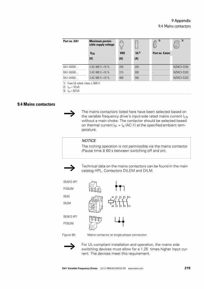
9 Appendix
9.4 Mains contactors
DA1 Variable Frequency Drives 10/12 MN04020005Z-EN www.eaton.com 219
9.4 Mains contactors
Figure 85: Mains contactor at single-phase connection
DA1-34202… 3 AC 480 V +10 % 250 250 - NZMC3-S250
DA1-34240… 3 AC 480 V +10 % 315 300 - NZMC3-S320
DA1-34302… 3 AC 480 V +10 % 400 350 - NZMC3-S320
1) Fuse UL-rated, class J, 600 V2) Icn = 10 kA3) Icn = 50 kA
Part no. DA1 Maximum permis-sible supply voltage
2) 3)
ULN VDE UL1) Part no. Eaton
[V] [A] [A]
→ The mains contactors listed here have been selected based on the variable frequency drive’s input-side rated mains current ILN without a main choke. The contactor should be selected based on thermal current Ith = Ie (AC-1) at the specified ambient tem-perature.
NOTICE
The inching operation is not permissible via the mains contactor (Pause time ≧ 60 s between switching off and on).
→ Technical data on the mains contactors can be found in the main catalog HPL, Contactors DILEM and DILM.
→ For UL-compliant installation and operation, the mains side switching devices must allow for a 1.25 times higher input cur-rent. The devices meet this requirement.
DILM12-XP1
P1DILEM
DILM,
DILEM
DILM12-XP1
P1DILEM
2
3 5
4 6
A1
A2
1 13
14

9 Appendix
9.4 Mains contactors
220 DA1 Variable Frequency Drives 10/12 MN04020005Z-EN www.eaton.com
Table 27: Assigned mains contactorsx
Part no. DA1 Rated operating voltage Rated input current Related mains contactor
(50 Hz) (60 Hz) Part no. Thermal current AC-1
ULN ULN ILN [A] IN [A] (+50 °C) IN [A] (+40 °C)
DA1-124D3… 1 AC 230 V 1 AC 240 V 8.5 DILM7 21 22
DA1-127D0… 1 AC 230 V 1 AC 240 V 13.9 DILM7 21 22
DA1-12011… 1 AC 230 V 1 AC 240 V 19.5 DILM17 38 40
DA1-324D3… 3 AC 230 V 3 AC 240 V 4.5 DILM7 21 22
DA1-327D0… 3 AC 230 V 3 AC 240 V 7.3 DILM7 21 22
DA1-32011… 3 AC 230 V 3 AC 240 V 11 DILM17 38 40
DA1-32018… 3 AC 230 V 3 AC 240 V 18.8 DILM17 38 40
DA1-32024… 3 AC 230 V 3 AC 240 V 24.8 DILM17 38 40
DA1-32039… 3 AC 230 V 3 AC 240 V 40 DILM40 57 60
DA1-32046… 3 AC 230 V 3 AC 240 V 47.1 DILM50 71 80
DA1-32061… 3 AC 230 V 3 AC 240 V 62.4 DILM65 88 98
DA1-32072… 3 AC 230 V 3 AC 240 V 74.1 DILM95 125 130
DA1-32090… 3 AC 230 V 3 AC 240 V 92.3 DILM115 142 160
DA1-32110… 3 AC 230 V 3 AC 240 V 112.7 DILM150 180 190
DA1-32150… 3 AC 230 V 3 AC 240 V 153.5 DILM185A 301 337
DA1-32011… 3 AC 230 V 3 AC 240 V 183.8 DILM185A 301 337
DA1-32202… 3 AC 230 V 3 AC 240 V 206.2 DILM185A 301 337
DA1-32248… 3 AC 230 V 3 AC 240 V 252.8 DILM250 360 400
DA1-342D2.. 3 AC 400 V 3 AC 480 V 2.4 DILM7 21 22
DA1-344D1… 3 AC 400 V 3 AC 480 V 4.3 DILM7 21 22
DA1-345D8… 3 AC 400 V 3 AC 480 V 6.1 DILM7 21 22
DA1-349D5… 3 AC 400 V 3 AC 480 V 9.8 DILM7 21 22
DA1-34014… 3 AC 400 V 3 AC 480 V 14.6 DILM17 38 40
DA1-34018… 3 AC 400 V 3 AC 480 V 18.1 DILM17 38 40
DA1-34024… 3 AC 400 V 3 AC 480 V 24.7 DILM17 38 40
DA1-34030… 3 AC 400 V 3 AC 480 V 30.8 DILM40 57 60
DA1-34039… 3 AC 400 V 3 AC 480 V 40 DILM50 71 80
DA1-34046… 3 AC 400 V 3 AC 480 V 47.1 DILM50 71 80
DA1-34061… 3 AC 400 V 3 AC 480 V 62.8 DILM80 98 110
DA1-34072… 3 AC 400 V 3 AC 480 V 73.8 DILM95 125 130
DA1-34090… 3 AC 400 V 3 AC 480 V 92.2 DILM115 142 160
DA1-34110… 3 AC 400 V 3 AC 480 V 112.5 DILM150 180 190
DA1-34150… 3 AC 400 V 3 AC 480 V 153.2 DILM185A 301 337
DA1-34180… 3 AC 400 V 3 AC 480 V 183.7 DILM185A 301 337
DA1-34202… 3 AC 400 V 3 AC 480 V 205.9 DILM185A 301 337
DA1-34240… 3 AC 400 V 3 AC 480 V 244.5 DILM250 360 400
DA1-34302… 3 AC 400 V 3 AC 480 V 307.8 DILM300A 385 430

DA1 Variable Frequency Drives 10/12 MN04020005Z-EN www.eaton.com 221
Alphabetical index
Numericals87-Hz Characteristic curve . . . . . . . . . . . . . . . . . . 40
AAbbreviations . . . . . . . . . . . . . . . . . . . . . . . . . . . . . . 6
AC-voltage system . . . . . . . . . . . . . . . . . . . . . . . . 30
AirBaffle . . . . . . . . . . . . . . . . . . . . . . . . . . . . . . . . 47
Circulation . . . . . . . . . . . . . . . . . . . . . . . . . . . . 46
Ambient Temperature . . . . . . . . . . . . . . . . . . . . . 24
Analog Input . . . . . . . . . . . . . . . . . . . . . . . . . . . . . 136
BBlock diagram
DA1 assemblies . . . . . . . . . . . . . . . . . . . . . . . 22
Brake chopper . . . . . . . . . . . . . . . . . . . . . . 13, 14, 19
Bus termination resistor . . . . . . . . . . . . . . . . . . . . 71
Bypass operation . . . . . . . . . . . . . . . . . . . . . . . . . . 42
CCable
Fuse protection and max.conductor cross sections . . . . . . . . . . . . . . 215
Cable cross-sections . . . . . . . . . . . . . . . . . . . . . . . 34
Catalog number selection . . . . . . . . . . . . . . . . . . 14
CE-Approval mark . . . . . . . . . . . . . . . . . . . . . . . . . 25
checklist . . . . . . . . . . . . . . . . . . . . . . . . . . . . . . . . . 75
Circuit type . . . . . . . . . . . . . . . . . . . . . . . . . . . . 24, 40
Clearances, thermal . . . . . . . . . . . . . . . . . . . . . . . 46
Commissioning . . . . . . . . . . . . . . . . . . . . . . . . . . . 75
Commutating choke, see main choke . . . . . . . . 33
Conformity (CE) . . . . . . . . . . . . . . . . . . . . . . . . . . . 37
Connecting the control section . . . . . . . . . . . . . . 64
Connecting the power section . . . . . . . . . . . . . . 59
Connectionasymmetrically earthed network . . . . . . . . . 30
Cable, screened . . . . . . . . . . . . . . . . . . . . . . . 62
Control signal terminal, example . . . . . . . . . 77
Digital input . . . . . . . . . . . . . . . . . . . . . . . . . . . 70
EX motors . . . . . . . . . . . . . . . . . . . . . . . . . . . . 43
in control section . . . . . . . . . . . . . . . . . . . . . . 64
in power section . . . . . . . . . . . . . . . . . . . . . . . 59
motor (block diagram) . . . . . . . . . . . . . . . . . . 22
Connection to IT networks . . . . . . . . . . . . . . . . . . 25
Control cables . . . . . . . . . . . . . . . . . . . . . . . . . . . . 56
Control inputsDefault settings . . . . . . . . . . . . . . . . . . . . . . . 67
Control panelmounting . . . . . . . . . . . . . . . . . . . . . . . . . . . . . 49
surface, calculation . . . . . . . . . . . . . . . . . . . . 49
Control panel dimensioning . . . . . . . . . . . . . . . . . 49
Control signal terminalsDesignation . . . . . . . . . . . . . . . . . . . . . . . . . . . 65
Function . . . . . . . . . . . . . . . . . . . . . . . . . . . . . . 66
Control terminal strip . . . . . . . . . . . . . . . . . . . . . . 64
Cooling . . . . . . . . . . . . . . . . . . . . . . . . . . . . . . . . . . 46
CRC (Cyclical Redundancy Check) . . . . . . . . . . 175
DDA1
Selection criteria . . . . . . . . . . . . . . . . . . . . . . . 24
System overview . . . . . . . . . . . . . . . . . . . . . . 10
Voltage categories . . . . . . . . . . . . . . . . . . . . . 13
DC current braking . . . . . . . . . . . . . . . . . . . . . . . 162
DC link voltage . . . . . . . . . . . . . . . . . . . . . . . . . . . . 27
Default settings . . . . . . . . . . . . . . . . . . . . . . . . . . . . 6
Degree of protection . . . . . . . . . . . . . . . . . . . . 13, 19
Degrees of protection . . . . . . . . . . . . . . . . . . . . . . . 9
Delta circuit . . . . . . . . . . . . . . . . . . . . . . . . . . . . . . 40
Digital inputConnection . . . . . . . . . . . . . . . . . . . . . . . . . . . 70
Digital outputConnection . . . . . . . . . . . . . . . . . . . . . . . . . . . 70
Dimensions . . . . . . . . . . . . . . . . . . . . . . . . . . . . . 209
Display unit . . . . . . . . . . . . . . . . . . . . . . . . . . . 14, 130
DS (default setting) . . . . . . . . . . . . . . . . . . . . . . . . . 6
EEarth-fault loop impedance . . . . . . . . . . . . . . . . . 54
Earth-fault protection . . . . . . . . . . . . . . . . . . . . . . 55
Earthing . . . . . . . . . . . . . . . . . . . . . . . . . . . . . . . . . . 54
Electrical Installation . . . . . . . . . . . . . . . . . . . . . . . 58
Electrical power network . . . . . . . . . . . . . . . . . . . 30
EMCCompliant setup, example . . . . . . . . . . . . . . 57
Earthing . . . . . . . . . . . . . . . . . . . . . . . . . . . . . . 54
electromagnetic compatibility . . . . . . . . . . . . 6
Measures in the control panel . . . . . . . . . . . 53
measures, general . . . . . . . . . . . . . . . . . . . . . 36
Screen earth kit . . . . . . . . . . . . . . . . . . . . . . . 56
EMC screw . . . . . . . . . . . . . . . . . . . . . . . . . . . 30, 55
Emitted interference . . . . . . . . . . . . . . . . . . . . . . . 37
EMT6 . . . . . . . . . . . . . . . . . . . . . . . . . . . . . . . . . . . . 43
Engineering . . . . . . . . . . . . . . . . . . . . . . . . . . . . . . 29

222 DA1 Variable Frequency Drives 10/12 MN04020005Z-EN www.eaton.com
Equipment supplied . . . . . . . . . . . . . . . . . . . . . . . 11
Errormemory . . . . . . . . . . . . . . . . . . . . . . . . . . . . . . 81
messages . . . . . . . . . . . . . . . . . . . . . . . . . . . . 81
ESD measures . . . . . . . . . . . . . . . . . . . . . . . . . . . . 65
Ex motors . . . . . . . . . . . . . . . . . . . . . . . . . . . . . . . . 43
FFault current (to earth) . . . . . . . . . . . . . . . . . . . . . 55
FE, see functional earth . . . . . . . . . . . . . . . . . . . . . 6
Features . . . . . . . . . . . . . . . . . . . . . . . . . . . . . . . . . 19
Fixed frequency . . . . . . . . . . . . . . . . . . . . . . . . . . 155
Fixed frequency setpoint values . . . . . . . . . . . . 155
Fixingon mounting rail . . . . . . . . . . . . . . . . . . . . . . . 51
with screws . . . . . . . . . . . . . . . . . . . . . . . . . . . 50
Frame sizesRadio interference suppression filter . . . . 209
Frequency . . . . . . . . . . . . . . . . . . . . . . . . . . . . . . . . 31
frequency jump . . . . . . . . . . . . . . . . . . . . . . . . . . 150
FS (frame size, size) . . . . . . . . . . . . . . . . . . . . . . . . 6
Functional earth . . . . . . . . . . . . . . . . . . . . . . . . . . . . 6
Fuses . . . . . . . . . . . . . . . . . . . . . . . . . . . . . . . . . . . . 34
FWD (forward run, clockwise rotation field) . . . . 6
GGND (ground) . . . . . . . . . . . . . . . . . . . . . . . . . . . . . . 6
Guidelines73/23/EEC . . . . . . . . . . . . . . . . . . . . . . . . . . . . 25
89/336/EEC . . . . . . . . . . . . . . . . . . . . . . . . . . . 25
89/392/EEC . . . . . . . . . . . . . . . . . . . . . . . . . . . 25
93/68/EEC . . . . . . . . . . . . . . . . . . . . . . . . . . . . 25
HHarmonics . . . . . . . . . . . . . . . . . . . . . . . . . . . . . . . 33
Hazard warnings, operational . . . . . . . . . . . . . . . 76
Heat dissipation . . . . . . . . . . . . . . . . . . . . . . . . . . . 49
Heat transfer coefficient . . . . . . . . . . . . . . . . . . . . 49
Hotline (Eaton Industries GmbH) . . . . . . . . . . . . 27
II/O (Control signal terminals) . . . . . . . . . . . . . . . . 65
IGBT . . . . . . . . . . . . . . . . . . . . . . . . . . . . . . . . . . . . . 6
Immission . . . . . . . . . . . . . . . . . . . . . . . . . . . . . . . . 37
Inching operation . . . . . . . . . . . . . . . . . . . . . . . . . . 77
Incoming unit, block diagram . . . . . . . . . . . . . . . . 22
Input process data . . . . . . . . . . . . . . . . . . . . . . . . 177
Inspection . . . . . . . . . . . . . . . . . . . . . . . . . . . . . . . . 26
Installation . . . . . . . . . . . . . . . . . . . . . . . . . . . . . . . 45
EMC-compatibility . . . . . . . . . . . . . . . . . . . . . 53
Instructional leaflet . . . . . . . . . . . . . . . . . . . . . . . . 12
IL04020009Z . . . . . . . . . . . . . . . . . . . . . . . . . . 12
IL04020013Z . . . . . . . . . . . . . . . . . . . . . . . . . . 12
IL04020014Z . . . . . . . . . . . . . . . . . . . . . . . . . . 12
InsulationResistance . . . . . . . . . . . . . . . . . . . . . . . . . . . . 74
Test . . . . . . . . . . . . . . . . . . . . . . . . . . . . . . . . . 74
Interference immunity . . . . . . . . . . . . . . . . . . . . . 37
Internal DC link . . . . . . . . . . . . . . . . . . . . . . . . . . . 22
Internal DC link capacitors . . . . . . . . . . . . . . . . . . 27
Inverter, block diagram . . . . . . . . . . . . . . . . . . . . . 22
IT network, connection . . . . . . . . . . . . . . . . . . . . . 30
LLCD . . . . . . . . . . . . . . . . . . . . . . . . . . . . . . . . . . . . . . 6
Leakage Current . . . . . . . . . . . . . . . . . . . . 35, 53, 58
Load Torque . . . . . . . . . . . . . . . . . . . . . . . . . . . . . . 24
MMagnet system . . . . . . . . . . . . . . . . . . . . . . . . . . . 29
Main choke . . . . . . . . . . . . . . . . . . . . . . . . . . . . . . . 33
Mains cable insulation . . . . . . . . . . . . . . . . . . . . . 74
Mains contactor . . . . . . . . . . . . . . . . . . . . . . . . . . . 36
Mains form . . . . . . . . . . . . . . . . . . . . . . . . . . . . . . . 30
Mains supply voltages . . . . . . . . . . . . . . . . . . . . . . 7
Mains voltage . . . . . . . . . . . . . . . . . . . . . . . . . . 24, 31
North American . . . . . . . . . . . . . . . . . . . . . . . . 7
Maintenance . . . . . . . . . . . . . . . . . . . . . . . . . . . . . 26
Manufacturing date . . . . . . . . . . . . . . . . . . . . . . . . 13
Menu navigation (operating unit) . . . . . . . . . . . 130
ModbusParameters . . . . . . . . . . . . . . . . . . . . . . . . . . 173
Register mapping . . . . . . . . . . . . . . . . . . . . . 177
RTU . . . . . . . . . . . . . . . . . . . . . . . . . . . . 171, 174
MotorCable insulation check . . . . . . . . . . . . . . . . . . 74
Cable, screened . . . . . . . . . . . . . . . . . . . . . . . 63
connection, block diagram . . . . . . . . . . . . . . 22
explosion-proof . . . . . . . . . . . . . . . . . . . . . . . . 43
Insulation test . . . . . . . . . . . . . . . . . . . . . . . . . 74
selection . . . . . . . . . . . . . . . . . . . . . . . . . . . . . 38
Motor cable . . . . . . . . . . . . . . . . . . . . . . . . . . . . . . 34
Motor earthing . . . . . . . . . . . . . . . . . . . . . . . . . . . . 55
Motor potentiometer . . . . . . . . . . . . . . . . . . . . . 138
Mounting . . . . . . . . . . . . . . . . . . . . . . . . . . . . . . . . 45
Mounting position . . . . . . . . . . . . . . . . . . . . . . . . . 46
NNameplate . . . . . . . . . . . . . . . . . . . . . . . . . . . . . . . 13

DA1 Variable Frequency Drives 10/12 MN04020005Z-EN www.eaton.com 223
OOperating mode
speed control . . . . . . . . . . . . . . . . . . . . . . . . . 38
V/Hz control . . . . . . . . . . . . . . . . . . . . . . . . . . . 38
Operating unit . . . . . . . . . . . . . . . . . . . . . . . . . . . 129
block diagram . . . . . . . . . . . . . . . . . . . . . . . . . 23
Operational data indicator . . . . . . . . . . . . . . . . . 168
PParallel
connection of several motors . . . . . . . . . . . . 24
operation, multiple motors . . . . . . . . . . . . . . 38
resonances . . . . . . . . . . . . . . . . . . . . . . . . . . . 33
Parameter software MaxConnect . . . . . . . . . . . 214
ParametersSetting . . . . . . . . . . . . . . . . . . . . . . . . . . . . . . 130
Upload/Download . . . . . . . . . . . . . . . . . . . . . 212
PDS (power drive system) . . . . . . . . . . . . . . . . . . . 6
PE . . . . . . . . . . . . . . . . . . . . . . . . . . . . . . . . . . . . . . . 6
PES (protective earth shielding) . . . . . . . . . . . . . . 6
PNU (parameter number) . . . . . . . . . . . . . . . . . . . . 6
Point-to-point connection . . . . . . . . . . . . . . . . . . 211
Power Drive System . . . . . . . . . . . . . . . . . . . . . . . 29
Power networksAC . . . . . . . . . . . . . . . . . . . . . . . . . . . . . . . . . . . 30
Grounded star point . . . . . . . . . . . . . . . . . . . . . 7
phase-earthed delta networks . . . . . . . . . . . 30
Ring . . . . . . . . . . . . . . . . . . . . . . . . . . . . . . . . . . 7
Star . . . . . . . . . . . . . . . . . . . . . . . . . . . . . . . . . . . 7
Power supply . . . . . . . . . . . . . . . . . . . . . . . . . . . . . 24
Power Wiring . . . . . . . . . . . . . . . . . . . . . . . . . . . . . 30
Protective earth . . . . . . . . . . . . . . . . . . . . . . . . . 6, 54
RRadio interference . . . . . . . . . . . . . . . . . . . . . . . . . 36
Radio interference filterBlock diagram . . . . . . . . . . . . . . . . . . . . . . . . . 22
Rated data . . . . . . . . . . . . . . . . . . . . . . . . . . . . . . . 13
Rated motor current . . . . . . . . . . . . . . . . . . . . . . . 24
Rated operational datageneral . . . . . . . . . . . . . . . . . . . . . . . . . . . . . . . 16
nameplate . . . . . . . . . . . . . . . . . . . . . . . . . . . . 13
Rating plate . . . . . . . . . . . . . . . . . . . . . . . . . . . . . . 40
Reactive power compensation devices . . . . . . . 33
Rectifier bridge . . . . . . . . . . . . . . . . . . . . . . . . . . . 22
Redundancy check, cyclic . . . . . . . . . . . . . . . . . 175
Relay outputs . . . . . . . . . . . . . . . . . . . . . . . . . . . . . 70
Residual current circuit breaker,see residual current device . . . . . . . . . . . . . . . . . 35
Residual current device . . . . . . . . . . . . . . . . . . . . 35
REV (reverse run, anticlockwise rotationfield active) . . . . . . . . . . . . . . . . . . . . . . . . . . . . . . . . 6
RJ45 interface . . . . . . . . . . . . . . . . . . . . . . . . . . . . 71
RS45 interface . . . . . . . . . . . . . . . . . . . . . . . . . . . . 71
SScaled value range . . . . . . . . . . . . . . . . . . . . . . . 137
Screen earth kit . . . . . . . . . . . . . . . . . . . . . . . . . . . 56
Selection criteria, for variable frequency drives 24
Self-test . . . . . . . . . . . . . . . . . . . . . . . . . . . . . . . . 130
Serial interface . . . . . . . . . . . . . . . . . . . . . . . . . . . 171
Serial number . . . . . . . . . . . . . . . . . . . . . . . . . . . . . 13
Service . . . . . . . . . . . . . . . . . . . . . . . . . . . . . . . . . . 27
Setpoint input . . . . . . . . . . . . . . . . . . . . . . . . . . . 169
Signal cables . . . . . . . . . . . . . . . . . . . . . . . . . . . . . 56
Sinusoidal filter . . . . . . . . . . . . . . . . . . . . . . . . 24, 43
Slip . . . . . . . . . . . . . . . . . . . . . . . . . . . . . . . . . . . . . 158
Slip compensation . . . . . . . . . . . . . . . . . . . . . . . . 158
Speed behaviorwith slip compensation . . . . . . . . . . . . . . . . 159
without slip compensation . . . . . . . . . . . . . 158
StandardsEN 50178 . . . . . . . . . . . . . . . . . . . . . . . . . . 34, 35
EN 60204 . . . . . . . . . . . . . . . . . . . . . . . . . . 25, 34
EN 60335 . . . . . . . . . . . . . . . . . . . . . . . . . . . . . 53
EN 60529 . . . . . . . . . . . . . . . . . . . . . . . . . . . . . 45
IEC 60034-1 . . . . . . . . . . . . . . . . . . . . . . . . . . 38
IEC 60038 . . . . . . . . . . . . . . . . . . . . . . . . . . . . 31
IEC 60364 . . . . . . . . . . . . . . . . . . . . . . . . . . . . 30
IEC 60947 . . . . . . . . . . . . . . . . . . . . . . . . . . . . 36
IEC 61557-8 . . . . . . . . . . . . . . . . . . . . . . . . . . 56
IEC 755 . . . . . . . . . . . . . . . . . . . . . . . . . . . . . . 35
IEC 890 . . . . . . . . . . . . . . . . . . . . . . . . . . . . . . 49
IEC/EN 60715 . . . . . . . . . . . . . . . . . . . . . . . . . 51
IEC/EN 61800-3 . . . . . . . . . . . . . . . . . . . . 32, 36
IEC/EN 61800-5-1 . . . . . . . . . . . . . . . . . . . . . . 58
VDE 0113 . . . . . . . . . . . . . . . . . . . . . . . . . . . . 34
VDE 0160 . . . . . . . . . . . . . . . . . . . . . . . . . 34, 53
VDE 017-1 . . . . . . . . . . . . . . . . . . . . . . . . . . . . 31
VDE 0289 . . . . . . . . . . . . . . . . . . . . . . . . . . . . 34
Star connection . . . . . . . . . . . . . . . . . . . . . . . . . . . 40
Starting torque . . . . . . . . . . . . . . . . . . . . . . . . . . . . 24
Stator windings, motor . . . . . . . . . . . . . . . . . . . . 153
Storage . . . . . . . . . . . . . . . . . . . . . . . . . . . . . . . . . . 26
Supply voltage . . . . . . . . . . . . . . . . . . . . . . . . . . . . 58
Support (Eaton Industries GmbH) . . . . . . . . . 6, 191
Surface mounting, EMC-compliant . . . . . . . . . . . 57
System earthing . . . . . . . . . . . . . . . . . . . . . . . . . . 54

224 DA1 Variable Frequency Drives 10/12 MN04020005Z-EN www.eaton.com
TTechnical data
Cables and fuses . . . . . . . . . . . . . . . . . . . . . 215
Temperature class . . . . . . . . . . . . . . . . . . . . . . . . . 40
Terminations . . . . . . . . . . . . . . . . . . . . . . . . . . . . . 61
THD (Total Harmonic Distortion) . . . . . . . . . . . . . 32
Three-phase asynchronous motor . . . . . . . . . . . 22
Three-wire control . . . . . . . . . . . . . . . . . . . . . . . . 143
Total harmonic distortion . . . . . . . . . . . . . . . . . . . 33
Transistor output . . . . . . . . . . . . . . . . . . . . . . . . . . 70
Two-wire control . . . . . . . . . . . . . . . . . . . . . . . . . 140
Typedesignation . . . . . . . . . . . . . . . . . . . . . . . . . . . 13
UUL (Underwriters Laboratories) . . . . . . . . . . . . . . . 6
Units . . . . . . . . . . . . . . . . . . . . . . . . . . . . . . . . . . . . . 7
Use (intended) . . . . . . . . . . . . . . . . . . . . . . . . . . . . 25
VV/f-characteristic curve . . . . . . . . . . . . . . . . . . . . . 41
VAR screw . . . . . . . . . . . . . . . . . . . . . . . . . . . . . . . 56
Voltage balance . . . . . . . . . . . . . . . . . . . . . . . . . . . 31
Voltage drop, permissible . . . . . . . . . . . . . . . . . . . . 7
WWarnings . . . . . . . . . . . . . . . . . . . . . . . . . . . . . . . . . 83
Warranty . . . . . . . . . . . . . . . . . . . . . . . . . . . . . . . . . 27