Embed Size (px)
Citation preview
PPCoN Additional Technical RequirementsPiping Design Requirements for Modifications to Existing Facilities
Phillips Petroleum Company Norway
PPCoN Additional Technical Requirements
Piping Design Requirements for Modifications to Existing Facilities
ContentsADDITIONAL REQUIREMENTS TO NORSOK STANDARDS 3
Disclaimer........................................................................................................................................ 3
1. INTRODUCTION 11.1 Objective and Scope.............................................................................................................11.2 Responsibility and Ownership...............................................................................................11.3 Approval................................................................................................................................ 11.4 Distribution............................................................................................................................ 11.5 Filing...................................................................................................................................... 11.6 Registration........................................................................................................................... 11.7 Abbreviations......................................................................................................................... 11.8 References............................................................................................................................ 2
1.8.1 NORSOK References.................................................................................................21.8.2 PPCoN References....................................................................................................21.8.3 Other References.......................................................................................................3
1.9 Non-Conformances...............................................................................................................3
2. TECHNICAL REQUIREMENTS 42.1 General................................................................................................................................. 4
2.1.1 Introduction................................................................................................................. 42.1.2 Piping Specifications...................................................................................................42.1.3 Valve Specifications....................................................................................................52.1.4 Material Data Sheets..................................................................................................52.1.5 Tie in Points Between Existing and New Specifications.............................................62.1.6 Surface Protection and Colour Coding of Piping........................................................62.1.7 Use of Dissimilar Materials.........................................................................................72.1.8 Design Requirement Selection...................................................................................72.1.9 Modification project.....................................................................................................72.1.10 Extension project........................................................................................................72.1.11 New system installation project..................................................................................7
2.2 Flanges and Fittings on P-Spec’s..........................................................................................82.2.1 Nipolet........................................................................................................................ 82.2.2 Screwed Pipe Plugs....................................................................................................82.2.3 Flat Faced Cast Iron Flanged Fittings.........................................................................82.2.4 Screwed Fittings.........................................................................................................82.2.5 Access under Pressure Fittings..................................................................................82.2.6 Slip Blinds and Spacers..............................................................................................82.2.7 Branch Connections...................................................................................................82.2.8 Bushings..................................................................................................................... 9
2.3 Bolting................................................................................................................................... 92.3.1 Threads...................................................................................................................... 92.3.2 Lengths....................................................................................................................... 92.3.3 Bolt Tightening............................................................................................................9
2.4 Special Applications..............................................................................................................92.4.1 Fire Water System......................................................................................................92.4.2 Erosion Spools for Cu-Ni Pipework............................................................................92.4.3 Vendor Package Design...........................................................................................10
2.5 L-002: Piping Design, Layout and Stress Analysis..............................................................102.5.1 Numbering Systems.................................................................................................10
DOCUMENT NO.: REVISION NO.: REVISION DATE: APPROVED:
4583 01 06-2000 Director, Maintenance4583 – PAGE I OF 52
PPCoN Additional Technical Requirements
Piping Design Requirements for Modifications to Existing Facilities
2.5.2 Valves Accessibility and Installation.........................................................................102.5.3 Sample Points..........................................................................................................102.5.4 Equipment Piping.....................................................................................................102.5.5 Fire/Explosion Protection..........................................................................................102.5.6 Fittings......................................................................................................................102.5.7 General.....................................................................................................................102.5.8 Loads from Piping System on Equipment.................................................................112.5.9 Deck and Wall Penetrations.....................................................................................11
2.6 Layout and Stress Analysis for GRP Piping........................................................................112.6.1 General.....................................................................................................................112.6.2 Layout....................................................................................................................... 112.6.3 Stress Analysis.........................................................................................................11
2.7 Supporting........................................................................................................................... 122.8 Demolition........................................................................................................................... 12
2.8.1 Dead Flow Sections..................................................................................................122.8.2 Redundant Sections.................................................................................................12
2.9 L-CR-003 : Piping Details....................................................................................................122.9.1 5.1 General...............................................................................................................122.9.2 Annex A Typical Drawings........................................................................................12
2.10 L-CR-004 : Piping Fabrication, Installation Flushing and Testing........................................122.10.1 12 System Colour Coding of Piping..........................................................................132.10.2 Annex A - Alternative Test Methods.........................................................................132.10.3 CS Production Flowlines...........................................................................................13
ANNEX A 14Cross Reference Table for Pipe Specifications..............................................................................14
ANNEX B 15Pipe Specifications.........................................................................................................................15
ANNEX C 16Valve Specifications.......................................................................................................................16
Ball Valves........................................................................................................................... 16Butterfly Valves...................................................................................................................17Gate Valves.........................................................................................................................17Globe Valves.......................................................................................................................18Check Valves......................................................................................................................19Plug Valves......................................................................................................................... 20
Notes for Valve Requisitioning.......................................................................................................21
ANNEX D 25Slip Blinds and Start Up Strainers..................................................................................................25
ANNEX E 44Variations In Design Principles......................................................................................................44
DOCUMENT NO.: REVISION NO.: REVISION DATE: APPROVED:
4583 01 06-2000 Director, Maintenance4583 – PAGE II OF 52
PPCoN Additional Technical Requirements
Piping Design Requirements for Modifications to Existing Facilities
ADDITIONAL REQUIREMENTS TO NORSOK STANDARDS
Disclaimer
NORSOK Standard Cross Reference:L-001 Piping and Valves, Rev.03
L-002 Piping Design, Layout and Stress Analysis. Rev. 02
L-CR-003 Piping Details, Rev.01
L-CR-004 Piping Fabrication, Installation, Flushing and Testing, Rev.01
"The Phillips Petroleum Company Norway specifications attached to this homepage are an unofficial and uncontrolled version and are set forth for information purposes only. Contractors who have contracts with Phillips Petroleum Company Norway are advised that they must comply with the binding, controlled version of the specifications set forth in their contracts with Phillips Petroleum Company Norway, and that they are responsible for ensuring proper compliance by their subcontractors with such controlled version of the specifications."
For information please contact the following:
Tor Tangeland – [email protected]
Jan E. Stene - [email protected]
DOCUMENT NO.: REVISION NO.: REVISION DATE: APPROVED:
4583 01 06-2000 Director, Maintenance4583 – PAGE 3 OF 52
PPCoN Additional Technical Requirements
Piping Design Requirements for Modifications to Existing Facilities
1. INTRODUCTION
1.1 Objective and ScopeThis document identifies the technical requirements for piping design in modification projects on Ekofisk field platforms. This comprises amongst others guidelines for where and when to apply the PPCoN ’P’ specifications in combination with NORSOK Pipe Class Sheets, the Eko II (Kværner) Pipe Class Sheets and the Eldfisk EWI (Aker Offshore Partner) Pipe Class Sheets. This document shall be read in conjunction with the supporting documents listed under section 1.8 References.
Note that there is not a 1:1 relationship between this document and Norsok L-001 and there is no reference to specific sections in L-001. This is, however, included for L-002, L-003 and L-004.
1.2 Responsibility and OwnershipLeader Inspection Planning is the owner of this document and is responsible for updating or withdrawal of the document as dictated by organizational or operational changes.
1.3 ApprovalThe procedure is approved by the Department Director, Maintenance.
1.4 DistributionThis document is distributed electronically only.
1.5 FilingThe Record Copy (RC) is filed by Department for Information Logistics.
1.6 RegistrationThe document is registered by its document number in PPCoN’s document administration system (FYI) which is administrated by the Department for Information Logistics
1.7 AbbreviationsCu-Ni Copper-Nickel CS Carbon-manganese steelGRP Glass-fibre Reinforced PlasticsDFI Design, fabrication and installationEDS Element Data SheetsMDS Material data sheet (NORSOK)MDT Minimum design temperature MSS Manufacturers Standardization Society of the Valve and Fitting IndustryNB Nominal BoreNFPA National Fire Protection AssociationNDE Non-Destructive Examination
DOCUMENT NO.: REVISION NO.: REVISION DATE: APPROVED:
4583 01 06-2000 Director, Maintenance4583 – PAGE 1 OF 52
PPCoN Additional Technical Requirements
Piping Design Requirements for Modifications to Existing Facilities
SS Stainless steelNPD OljedirektoratetAPI American Petroleum Institute NORSOK Norsk Sokkels KonkurranseposisjonNSDP North Sea Design Premises (PPCoN)PCS Pipe Class Sheet (NORSOK)RF Raised face RTJ Ring type joint UKOOA UK Offshore Operators AssociationVDS Valve Data Sheet (NORSOK)TAG Teknisk Ansvarlig Gruppe ( i PPCoN)
1.8 References
1.8.1 NORSOK ReferencesL-001 Piping and ValvesL-002 Piping Design, Layout and Stress AnalysisL-CR-003 Piping DetailsL-CR-004 Piping Fabrication, Installation, Flushing and Pressure TestingM-001 Material SelectionM-CR-621 GRP Piping MaterialsM-501 Surface Preparation and Protective CoatingM-630 Material Data Sheets PipingR-001 Mechanical EquipmentP-001 Process DesignH-CR-002 Piping and Plumbing
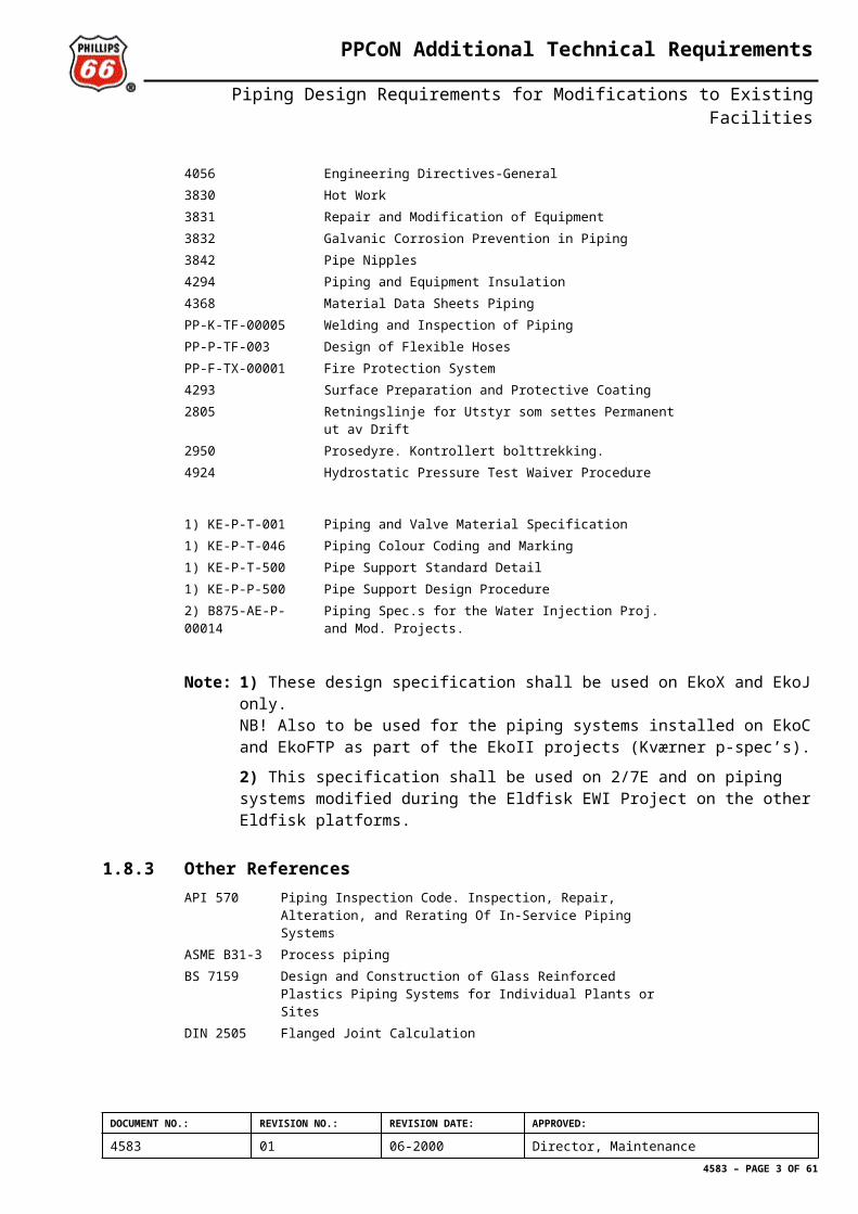
1.8.2 PPCoN References4920 Control of Non-Conformity4056 Engineering Directives-General3830 Hot Work3831 Repair and Modification of Equipment3832 Galvanic Corrosion Prevention in Piping3842 Pipe Nipples4294 Piping and Equipment Insulation4368 Material Data Sheets PipingPP-K-TF-00005 Welding and Inspection of PipingPP-P-TF-003 Design of Flexible HosesPP-F-TX-00001 Fire Protection System4293 Surface Preparation and Protective Coating2805 Retningslinje for Utstyr som settes Permanent ut av Drift2950 Prosedyre. Kontrollert bolttrekking.4924 Hydrostatic Pressure Test Waiver Procedure
1) KE-P-T-001 Piping and Valve Material Specification1) KE-P-T-046 Piping Colour Coding and Marking1) KE-P-T-500 Pipe Support Standard Detail1) KE-P-P-500 Pipe Support Design Procedure2) B875-AE-P-00014 Piping Spec.s for the Water Injection Proj. and Mod. Projects.
DOCUMENT NO.: REVISION NO.: REVISION DATE: APPROVED:
4583 01 06-2000 Director, Maintenance4583 – PAGE 2 OF 52
PPCoN Additional Technical Requirements
Piping Design Requirements for Modifications to Existing Facilities
Note: 1) These design specification shall be used on EkoX and EkoJ only.NB! Also to be used for the piping systems installed on EkoC and EkoFTP as part of the EkoII projects (Kværner p-spec’s).
2) This specification shall be used on 2/7E and on piping systems modified during the Eldfisk EWI Project on the other Eldfisk platforms.
1.8.3 Other ReferencesAPI 570 Piping Inspection Code. Inspection, Repair, Alteration, and
Rerating Of In-Service Piping SystemsASME B31-3 Process pipingBS 7159 Design and Construction of Glass Reinforced Plastics Piping
Systems for Individual Plants or SitesDIN 2505 Flanged Joint Calculation
1.9 Non-ConformancesThis document contains both requirements and recommendations. Deviations from requirements contained in this document shall be addressed to the position responsible for this document, according to document no. 4920 “Control of Non-Conformity”. Reporting according to procedure no. 4920 is not required for deviations from recommendations, however, significant deviations shall be reported to the position responsible for this document.
DOCUMENT NO.: REVISION NO.: REVISION DATE: APPROVED:
4583 01 06-2000 Director, Maintenance4583 – PAGE 3 OF 52
PPCoN Additional Technical Requirements
Piping Design Requirements for Modifications to Existing Facilities
2. TECHNICAL REQUIREMENTS
2.1 GeneralModifications to the existing facilities shall comply with the relevant NPD regulations and conform to ASME B31.3, API 570 and this documet.
2.1.1 IntroductionOriginal piping design on PPCoN operated platforms have been to various sets of specifications (e.g. Brown & Root, Worley, Kvaerner, Tecnomare etc.). From 1987 and the introduction of North Sea Design Premises, section 12 'Topside Piping Design', new platforms and modifications to exiting facilities and systems have been done in accordance to specifications given therein. From 1994, NSDP has been withdrawn as an official design requirement and is to the extent possible replaced by NORSOK.
Requirements given in the PPCoN document 4056 'Engineering Directives General' and PPCoN TCD level 2 documents normally linked to the individual NORSOK standards shall be used in addition to NORSOK.
Modifications to existing facilities shall to the extent possible be done within the NORSOK technical envelope. However, where NORSOK does not match the conditions of the existing platform systems, retained P-specs will apply, as described in Section 2.1.2 Piping Specifications. For the EkoX and EkoJ platforms, the original design specifications listed in Section 1.8 References shall apply. Some exceptions to the referred NORSOK standards will also apply, as stated in this document.
For 2/7E and piping systems modified during the Eldfisk EWI Project on the other Eldfisk platforms the original PCSs (B875-AE-P-00014) shall apply. This document contains basically “plain” Norsok PCSs, but some project specific PCSs have been developed to cover the “voids” in Norsok.
NB! The Norsok MDSs with PPCoN’s additional requirements outlined in doc. 4368 shall be applied for all modification projects (i.e. the Eko II MDS’ shall not be applied).
The Element Data Sheets (EDS) shall follow the respective piping specification (KE-spec. or NORSOK spec.)
2.1.2 Piping SpecificationsSeveral PPCoN ’P-specifications’ have been replaced by NORSOK PCSs. Some P-specs need to be retained, due to special design features and/or materials in use (eg. ’monel’). A cross-reference index for accepted specifications is given i Annex A. P-specifications are listed in Annex B.
For 2/4X and 2/4J platform modifications, KE-P-T-001 ”Piping and Valve Material Specification” shall be followed (see Section 2.1.3 Valve Specifications for selection of VDS’). The same applies to piping systems on 2/4C and 2/4FTP installed as part of EkoII project.
For 2/7E and piping systems modified during the Eldfisk EWI Project on the other Eldfisk platforms the original PCSs (B875-AE-P-00014) shall apply. This document contains basically “plain” Norsok PCSs but some project specific PCSs have been developed to cover the “voids” in Norsok.
DOCUMENT NO.: REVISION NO.: REVISION DATE: APPROVED:
4583 01 06-2000 Director, Maintenance4583 – PAGE 4 OF 52
PPCoN Additional Technical Requirements
Piping Design Requirements for Modifications to Existing Facilities
In general all hydrocarbon (oil, gas, produced water and oily water) piping systems shall be designed for sour service. For the Eko II PCSs the Service Class Summary defines which piping systems are designed for sour service. For the PPCoN P-specs the requirements to sour service are identified on the respective P-specs.
Design pressure and temperatureP-specs are developed for a certain set of service mediums and corresponding pressure and temperature conditions. Some specifications are given intermediate pressure rating; thus allowing the use of reduced schedule for piping. Some specification also have API 6A designated rating.
PCS's are developed for a limited number of standard materials in all pressure classes. No intermediate rating is available. Thus, special consideration to design pressure should be made when tie-ins to existing systems are made. Also consider that the minimum design temperature (MDT) may deviate from the “corresponding” Norsok PCS’s in some cases.
Tie-in to existing systemsExisting systems have been designed to either NSDP or original design specifications. NSDP is field-wide identical, while original specifications vary between platforms. For tie-in of new systems to the existing systems, the following points must always be checked:
design pressure
design temperature range
system test pressure
materials and their strength
pipe schedule, wall thickness and corrosion allowance
type of flanges, hub connections and gasket type in use
valve specifications and rating.
For more information see Annex E - Variations in design principles.
2.1.3 Valve SpecificationsValve specifications are listed in Annex C. For valve selections see NORSOK L-001, Section 5 ”Valve Selection Manual”.
Valve Data Sheets identified within each relevant Piping Class Sheet as per KE-P-T-001 Piping and Valve Material Spesification (EKO II) and the PPCoN P-specs shall be substituted by the corresponding NORSOK VDS. This includes all referenced Norsok Standards and Datasheets. If similar datasheet does not exist within the NORSOK Standard, the VDS within KE-P-T-001 or the valve data sheet listed in Annex C shall be used.
2.1.4 Material Data SheetsIndependent of piping specification the NORSOK MDSs (M-630) and PPCoN doc. 4368 shall be employed.
DOCUMENT NO.: REVISION NO.: REVISION DATE: APPROVED:
4583 01 06-2000 Director, Maintenance4583 – PAGE 5 OF 52
PPCoN Additional Technical Requirements
Piping Design Requirements for Modifications to Existing Facilities
2.1.5 Tie in Points Between Existing and New SpecificationsThe existing piping specifications are either original platform specifications or P-specifications (Annex B). New piping specifications will be those used by KE-P-T-001 (2/4X and 2/4J Platforms), NORSOK L-001 and B875-AE-P-00014 (2/7E and the piping systems modified during the EWI Project on the Eldfisk platforms).
It is imperative that tie-ins between different piping specifications receive individual consideration by a piping design engineer. See PP-P-TF-00001 for aspects to be considered when tie ins between existing and new specifications shall be done.
2.1.6 Surface Protection and Colour Coding of PipingSurface Protection of piping and equipment shall fullfill requirements given in doc. no. 4293 ”Surface Preparation and Protective Coating.
All pipework shall be color coded in accordance with the service. (Based on ISO Standard R-508)
Basic identification color(s) and their meaning (except EkoX and EkoJ):Red with white arrow - Fire WaterRed with yellow arrow - Foam/dry chemicalRed with blue arrow - CO2/Inergen/gas extinguishing systemsGreen with blue arrow - Potable waterGreen with white arrow - Raw or salt water in liquid stateSilver-Grey with white arrow - SteamBrown with white arrow - All combustible oilsYellow-ochre with white arrow - All gases (except air or liquefied gases)Violet with white arrow - Acids or alkalisLight blue with white arrow - AirBlack with white arrow - Any other liquids
Color bands on piping shall be at least 15 cm in width. The arrow incorporated into band shall indicate of flow. The pipeline content shall be labelled in black on the arrow.
Exceptions:All valves for fire water service shall be painted red.
If the transported material is poisonous or would cause chemical burns upon contact with skin an additional band (at least 15 cm in width) with yellow and black diagonal stripes shall be placed in conjunction with the identification marking.
These markings shall be installed at wall and deck penetrations, on both sides of valves at service connection and at pipeline junctions. Pipelines between platforms shall be labelled at each end of pipe bridge and once in the middle. Additional markings may be installed as desired for operator convenience.
Pipework on EkoX and EkoJ shall be colour marked in accordance with KE-P-T-046 ”Piping Colour Coding and Marking”.
NB! Colour coding on stainless steel (316, super duplex, etc.) shall be of a stand off sign type with minimal contact with the pipe. Plastic sheets wrapped around the pipe is not acceptable as water and dirt are trapped and could cause corrosion/cracking.
DOCUMENT NO.: REVISION NO.: REVISION DATE: APPROVED:
4583 01 06-2000 Director, Maintenance4583 – PAGE 6 OF 52
PPCoN Additional Technical Requirements
Piping Design Requirements for Modifications to Existing Facilities
2.1.7 Use of Dissimilar MaterialsThe use of metals with diffferences in galvanic potential may require the use of insulation spools. Reference is made to TCD 2 4650 ”Material Selections” for requirements regarding insulation spools.
2.1.8 Design Requirement SelectionProjects may vary in size and complexity. The following definitions of project category shall be basis for selection of design standards and specifications. See below.
2.1.9 Modification projectThe piping part of the project is a modification of an existing system. The project may include new piping, new mechanical or process equipment. New routing and layout may be included, but only as replacement of existing lines. New dimensions for piping, based on changes in plant capacity may also be a part of such a project.
Example: Replacement of an old pump, including new suct./disch. piping. Changing out a corroded production flowline. Reduce diameter of a pipe system to maintain a minimum flow velocity requirement.
Piping design requirement:All modification category projects shall be executed following this document . See 2.1.2 Piping Specifications. This to obtain interchangeability of components, equal hub types, flange facings, gasket and bolt materials. This will result in increased flexibility on component and reduced spare stocking for PPCoN.
2.1.10 Extension projectThe project scope will extend an existing system to new modules/areas, or extend capacity by duplication of existing lines/trains. This may also include increased size of main distribution manifolds and replacement of equipment by a new unit with different capacity.
Example: Extension of a fire water system to cover new areas, or to increase capacity in a certain area. Installing one (or several) new gas lift lines to a production platform already having such equipment on some wells.
Piping design requirement:Extensions to existing systems, where the majority of new piping are in the same size, pressure class and material type as already used on the subject system shall follow Section 2.1.2 Piping Specifications.
Extensions to existing systems where the majority of the new piping is of other size, pressure class or material type than the existing part of the system shall follow NORSOK Piping Design Requirements, as described in Section 2.1.1 Introduction. This to fully utilise the NORSOK effect on design, fabrication and testing of components and systems.
2.1.11 New system installation projectA new system is added to the existing facility. The system tie-ins to existing pipework may typically be tie-in to utility supplies, tie-in to cooling water main distribution, tie-in to existing process systems etc.
DOCUMENT NO.: REVISION NO.: REVISION DATE: APPROVED:
4583 01 06-2000 Director, Maintenance4583 – PAGE 7 OF 52
PPCoN Additional Technical Requirements
Piping Design Requirements for Modifications to Existing Facilities
Example: Installation of a complete gas lift unit on an existing production platform. Installation of a new chemical injection system to an existing production train.
Piping design requirement:All new system installation category projects shall follow NORSOK Piping Design Requirements, as described in Section 2.1.1 Introduction.
This to obtain the NORSOK effect regarding standardisation, as well as simplified functional oriented requirements on design, fabrication and testing.
2.2 Flanges and Fittings on P-Spec’s
2.2.1 NipoletA nipolet is a reinforced branch fitting not more than 2” NB, 12 inches or less in length, that eliminates the branch combination of nipple, ’o’let and one weld. All nipolets shall be stamped with schedule, type of material and trademark.
2.2.2 Screwed Pipe PlugsScrewed Pipe Plugs shall be solid and long enough to extend through insulation, minimum 2” long (including thread length). ”Solid” shall be stamped on the plug (not engraved).
2.2.3 Flat Faced Cast Iron Flanged FittingsWhenever Flat Faced Cast Iron Flanged Fittings are used in utility piping the steel mating flange shall be flat face and full face gaskets shall be used. Flanges shall be flat face where connected to flat face pumps, turbines, compressors or other equipment nozzles.
2.2.4 Screwed FittingsScrewed Fittings shall be threaded NPT (ANSI B1.20.1 General Purpose Pipe Threads).
2.2.5 Access under Pressure FittingsAccess under Pressure Fittings shall comply with the requirements of the respective P-spec and be of the Cosasco FLARWELD body type or similar. Assembly type will be solid plug with a heavy protective cover withot a hole.
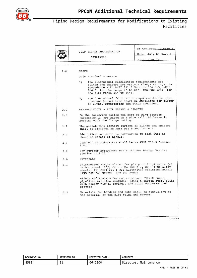
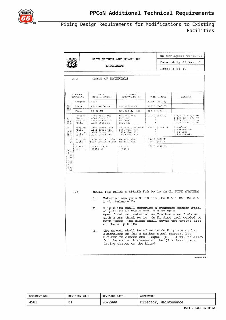
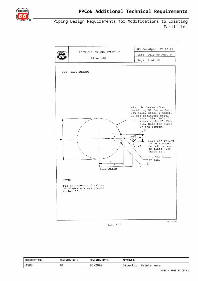
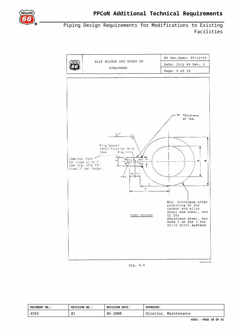
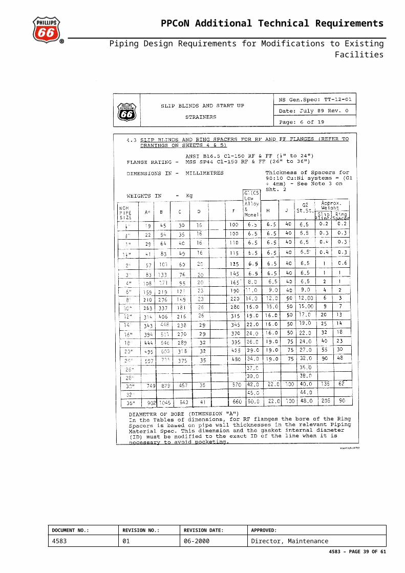
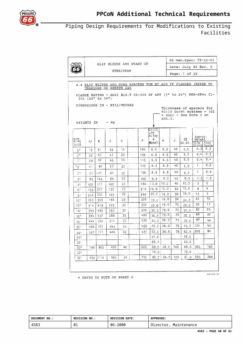
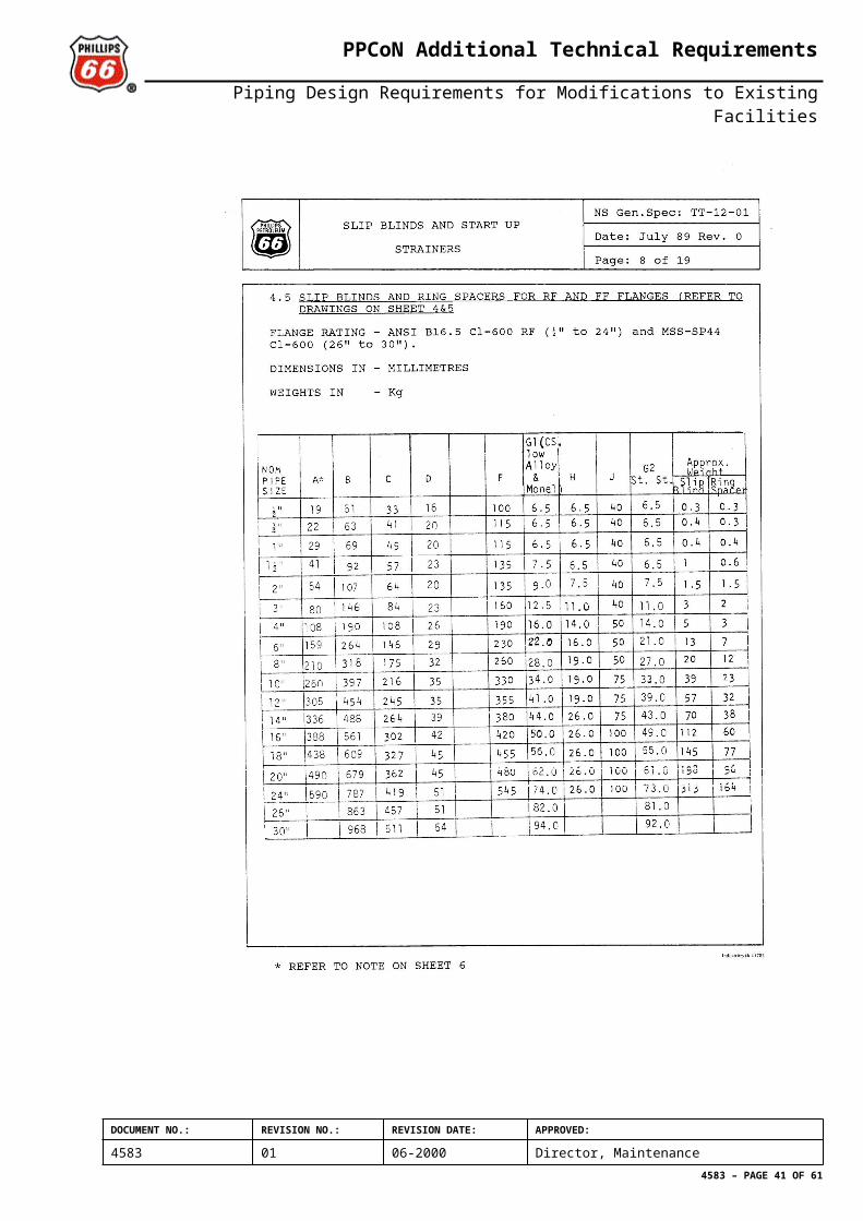
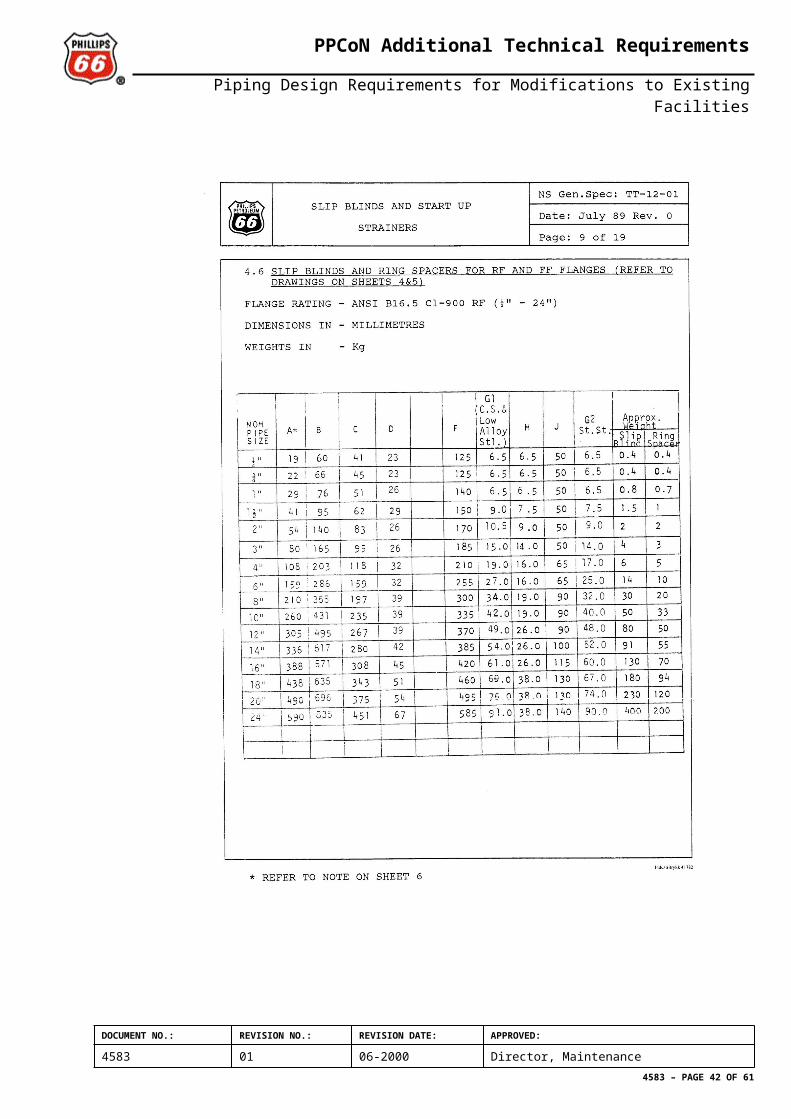
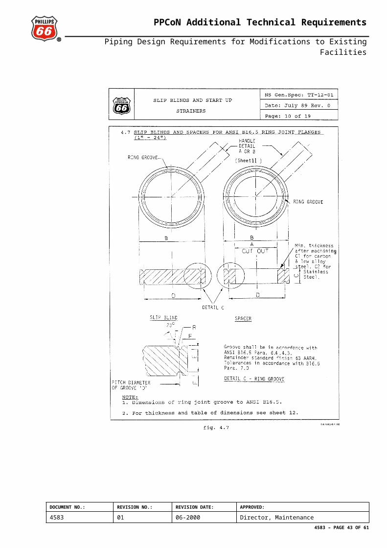
2.2.6 Slip Blinds and SpacersAll blinds shall follow ASME B16.5 pressure rating. Blinds shall have a minimum thickness according to ASME B31.3, sect. 304.5.3, formula (15). Guidelines are given in Annex D (TT-12-01 ”Slip Blinds and Start up Strainers”) for dimension of blinds in existing systems designed in accordanse with P-specs. Slip blinds for RF flanges shall have flat face. Slip blinds for RTJ flanges shall have RTJ facing.
2.2.7 Branch ConnectionsThese shall normally comply with the relevant pipe specification’s table of header-to-branch requirements. Where exceptions are necessary, flanged fittings, branch fittings, extrusions or tees of proper wall thickness are permitted . This includes the use of one piece flanged forged branch fittings.
DOCUMENT NO.: REVISION NO.: REVISION DATE: APPROVED:
4583 01 06-2000 Director, Maintenance4583 – PAGE 8 OF 52
PPCoN Additional Technical Requirements
Piping Design Requirements for Modifications to Existing Facilities
2.2.8 BushingsBushings may only be specified after PPCoN approval, for use on non-hydrocarbon service below 300 psig design pressure. The use of bushings should then be kept to a minimum, and may only be considered where there is limited space or where other methods of change in pipe diameter are impractical.
The change in pipe size must be two or more nominal diameters e.g., 1” to ½” ( for structural strenght).
2.3 Bolting
2.3.1 ThreadsBolting threads for alloy steel studs shall be made to ASME B1.20.1 and in accordance with ANSI B16.5 clause 6.9.5 (i.e., Coarse thread series for 1 inch dia. and smaller; 8 thread series for 1-1/8 inch dia. and larger).
2.3.2 LengthsBolt lengths shall be in accordance with ANSI B 16.5.
2.3.3 Bolt TighteningControlled Bolt Tightening comprises both manually torque, hydraulic bolt torque and hydraulic bolt tensioning, and shall be applied to all ranges of bolted flange connections. For bolt diameters 1” and larger, hydraulic bolt tightening is required. Both torque and tension principles are defined as hydraulic bolt tightening.
Bolting and calculation of required bolt stress values shall be in accordance to DIN 2505, with the additional requirements set in NORSOK L-CR-004 and the bolting procedures contained in ”PPCoN’s Doc.no. 2950. L-CR-004 does not apply for GRP piping systems and wellhead equipment. These issues are specially addressed in the PPCoN Doc.no. 2950.
2.4 Special Applications
2.4.1 Fire Water SystemTechnical requirements for design is given in PP-F-TX-00001 ”Fire Pumps and Mains, Deluge and Sprinkler Systems”. A fire water system shall be designed in accordance with NFPA standards unless otherwise provided in project premises or contract documents.
2.4.2 Erosion Spools for Cu-Ni PipeworkRapid erosion can take place downstream of throttling valves due to high velocity seawater impinging on the Cu-Ni line. To combat this, a SS spool (to Norsok PCS AD30) shall be installed downstream of the subject valve. Spool length shall be min. 3x NB. The erosion spool shall further be insulated from the CuNi pipe at the extreme downstream flange (not the valve end) for galvanic corrosion purposes. See reference in Section 2.1.7 Use of Dissimilar Materials.
DOCUMENT NO.: REVISION NO.: REVISION DATE: APPROVED:
4583 01 06-2000 Director, Maintenance4583 – PAGE 9 OF 52
PPCoN Additional Technical Requirements
Piping Design Requirements for Modifications to Existing Facilities
2.4.3 Vendor Package DesignIf vendor see benefits on cost and technical solutions for PPCoN, then package design may follow the vendor's in-house specifications. However, before vendor's in-house specifications can be used PPCoN's piping engineer (TAG-piping ) approval must be obtained.
If vendor is unable to use proper in-house specifications for piping inside the package, then design shall be to the same pipe specifications as used for the rest of the system. See Section 2.1.1 Introduction.
2.5 L-002: Piping Design, Layout and Stress AnalysisFor steel piping, NORSOK standard L-002 shall apply, with the following exceptions:
2.5.1 Numbering SystemsThe PPCoN Engineering Numbering System (PENS), Doc. No. 2169 manual shall apply.
2.5.2 Valves Accessibility and InstallationNormally, valves shall be installed with the stem located above the horisontal plane through the valve centerline. Valve stem orientation shall be shown on both piping plans and piping isometrics. Butterfly valves of 12 inch nominal bore and greater shall be installed with the stem horizontal, where possible. Turbulance/vibration problems may overrule this criterion (e.g.: close to a vertical bend valve stem to be vertical).
2.5.3 Sample PointsAccess under Pressure Fittings shall comply with the requirements of the respective P-spec and be of the Cosasco FLARWELD body type or similar. Assembly type will be solid plug with a heavy protective cover without a hole.
2.5.4 Equipment Piping GeneralWhen new piping is to be connected to old equipment, the maximum allowable dead and operating loads as specified in R-001 do not automaticly apply. A verification of load limits shall be performed.
2.5.5 Fire/Explosion ProtectionFor modification projects on existing facilities, the accidental load requirements will be given by PPCoN.
2.5.6 FittingsL-002 does not apply. See Section 2.2 Flanges and Fittings on P-Spec’s in this document.
2.5.7 GeneralPPCoN responsible piping / valve TAG-engineer shall be consulted prior to any change to pipework and valves classed as ”critical”, as defined in Critical Line List for the installation and / or NORSOK L-002, section 5.2.
DOCUMENT NO.: REVISION NO.: REVISION DATE: APPROVED:
4583 01 06-2000 Director, Maintenance4583 – PAGE 10 OF 52
PPCoN Additional Technical Requirements
Piping Design Requirements for Modifications to Existing Facilities
All engineering and modification work performed on piping systems termed ”critical” by the Critical Line list and / or L-002, section 5.2 shall be checked by a piping stress-engineer and have independent design verification. The independent verification shall be performed in parallel with the engineering work. The extent and degree of independence of the verification shall be agreed with the PPCoN responsible TAG-engineer at start up of the modification project.
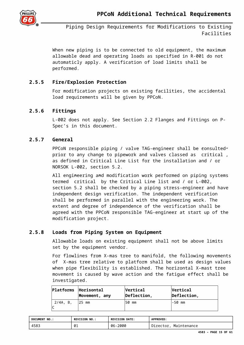
2.5.8 Loads from Piping System on EquipmentAllowable loads on existing equipment shall not be above limits set by the equipment vendor.
For flowlines from X-mas tree to manifold, the following movements of X-mas tree relative to platform shall be used as design values when pipe flexibility is established. The horizontal X–mast tree movement is caused by wave action and the fatigue effect shall be investigated.
Platforms Horisontal Movement, any Direction
Vertical Deflection, Upwards
Vertical Deflection, Downwards
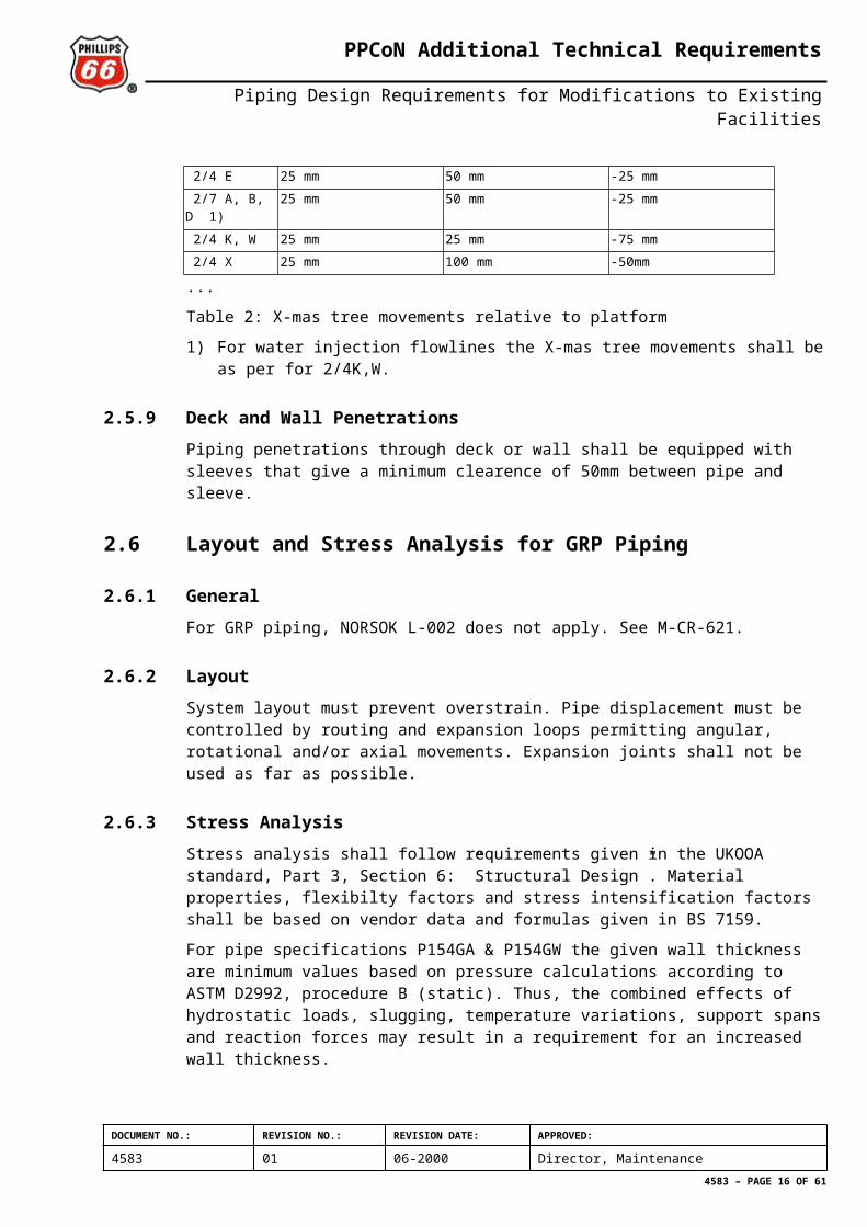
2/4A, B, C 25 mm 50 mm -50 mm 2/4 E 25 mm 50 mm -25 mm 2/7 A, B, D 1) 25 mm 50 mm -25 mm 2/4 K, W 25 mm 25 mm -75 mm 2/4 X 25 mm 100 mm -50mm
...
Table 2: X-mas tree movements relative to platform
1) For water injection flowlines the X-mas tree movements shall be as per for 2/4K,W.
2.5.9 Deck and Wall PenetrationsPiping penetrations through deck or wall shall be equipped with sleeves that give a minimum clearence of 50mm between pipe and sleeve.
2.6 Layout and Stress Analysis for GRP Piping
2.6.1 GeneralFor GRP piping, NORSOK L-002 does not apply. See M-CR-621.
2.6.2 LayoutSystem layout must prevent overstrain. Pipe displacement must be controlled by routing and expansion loops permitting angular, rotational and/or axial movements. Expansion joints shall not be used as far as possible.
2.6.3 Stress AnalysisStress analysis shall follow requirements given in the UKOOA standard, Part 3, Section 6: ”Structural Design”. Material properties, flexibilty factors and stress intensification factors shall be based on vendor data and formulas given in BS 7159.
DOCUMENT NO.: REVISION NO.: REVISION DATE: APPROVED:
4583 01 06-2000 Director, Maintenance4583 – PAGE 11 OF 52
PPCoN Additional Technical Requirements
Piping Design Requirements for Modifications to Existing Facilities
For pipe specifications P154GA & P154GW the given wall thickness are minimum values based on pressure calculations according to ASTM D2992, procedure B (static). Thus, the combined effects of hydrostatic loads, slugging, temperature variations, support spans and reaction forces may result in a requirement for an increased wall thickness.
2.7 SupportingStandard support details for all modification projects shall be as defined in KE-P-T-500 ”Pipe support Standard Details” and KE-P-P-500 ”Pipe Support Design Procedure”.
GRP piping shall be supported according to the pipe vendors engineering guidelines. Support design shall allow for expansion, contraction and deflection resulting from pressurization, temperature variations, slugging (water hammer) and weight of the pipe content. Special attention shall be given to proper supporting of metal valves and other mechanical equipment installed in the system.
2.8 Demolition
2.8.1 Dead Flow Sections If changes are made to existing pipework that result in a ”dead flow” section of line (and there is no forseeable use for that section) then it shall be removed.
2.8.2 Redundant SectionsIf changes are made to existing pipework that result in redundant disconnected sections of line, then these shall be removed.
Please note: For Ekofisk platforms with limited lifetime an acceptable alternative to removal will be to blind off and scrap-in-place.
See document no. 2805 ”Retningslinjer for utstyr som settes permanent ut av drift”.
2.9 L-CR-003 : Piping DetailsNORSOK standard L-CR-003 shall apply with the following exceptions:
2.9.1 5.1 GeneralWhen NORSOK PCSs are used, the Piping Details in L-CR-003 shall apply. If original P-specifications are used, the Piping Details shall be used as guidelines and modified to suit the P-specifications with respect to flange facing etc.
2.9.2 Annex A Typical DrawingsPiping Detail (PD) 129 ”Typical utility station concept” does not apply. Modifications shall be based on existing lay-out.
2.10 L-CR-004 : Piping Fabrication, Installation Flushing and TestingNORSOK standard L-CR-004 shall apply with the following exceptions:
DOCUMENT NO.: REVISION NO.: REVISION DATE: APPROVED:
4583 01 06-2000 Director, Maintenance4583 – PAGE 12 OF 52
PPCoN Additional Technical Requirements
Piping Design Requirements for Modifications to Existing Facilities
2.10.1 12 System Colour Coding of PipingColour coding of piping system shall be in accordance with Section 2.1.6 Surface Protection and Colour Coding of Piping for all platforms except 2/4X and 2/4J, which shall be colour coded according to KE-P-T-046.
2.10.2 Annex A - Alternative Test MethodsA2 General: Prior to any alternative testing taking place, acceptance shall be obtained as outlined in PPCoN doc 4924.
2.10.3 CS Production FlowlinesAll welding on CS production flowlines shall be Post Weld Heat Treated (PWHT) according to PP-K-TF-00005.
DOCUMENT NO.: REVISION NO.: REVISION DATE: APPROVED:
4583 01 06-2000 Director, Maintenance4583 – PAGE 13 OF 52
PPCoN Additional Technical Requirements
Piping Design Requirements for Modifications to Existing Facilities
ANNEX A
Cross Reference Table for Pipe SpecificationsClick here to see all specifications in Annex A Rev 2000.
DOCUMENT NO.: REVISION NO.: REVISION DATE: APPROVED:
4583 01 06-2000 Director, Maintenance4583 – PAGE 14 OF 52
PPCoN Additional Technical Requirements
Piping Design Requirements for Modifications to Existing Facilities
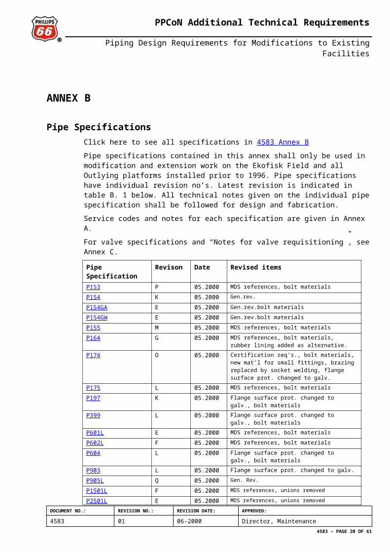
ANNEX B
Pipe Specifications Click here to see all specifications in 4583 Annex B
Pipe specifications contained in this annex shall only be used in modification and extension work on the Ekofisk Field and all Outlying platforms installed prior to 1996. Pipe specifications have individual revision no’s. Latest revision is indicated in table B. 1 below. All technical notes given on the individual pipe specification shall be followed for design and fabrication.
Service codes and notes for each specification are given in Annex A.
For valve specifications and “Notes for valve requisitioning”, see Annex C.
Pipe Specification Revison Date Revised items P153 P 05.2000 MDS references, bolt materials
P154 K 05.2000 Gen.rev.
P154GA E 05.2000 Gen.rev.bolt materials
P154GW E 05.2000 Gen.rev.bolt materials
P155 M 05.2000 MDS references, bolt materials
P164 G 05.2000 MDS references, bolt materials, rubber lining added as alternative.
P174 O 05.2000 Certification req’s., bolt materials, new mat’l for small fittings, brazing replaced by socket welding, flange surface prot. changed to galv.
P175 L 05.2000 MDS references, bolt materials
P197 K 05.2000 Flange surface prot. changed to galv., bolt materials
P399 L 05.2000 Flange surface prot. changed to galv., bolt materials
P601L E 05.2000 MDS references, bolt materials
P602L F 05.2000 MDS references, bolt materials
P604 L 05.2000 Flange surface prot. changed to galv., bolt materials
P903 L 05.2000 Flange surface prot. changed to galv.
P905L Q 05.2000 Gen. Rev.
P1501L F 05.2000 MDS references, unions removed
P2501L E 05.2000 MDS references, unions removed
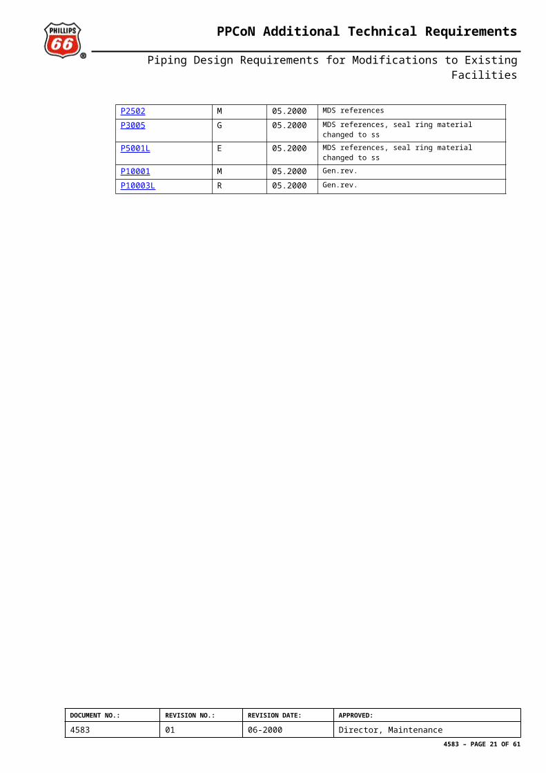
P2502 M 05.2000 MDS references
P3005 G 05.2000 MDS references, seal ring material changed to ss
P5001L E 05.2000 MDS references, seal ring material changed to ss
P10001 M 05.2000 Gen.rev.
P10003L R 05.2000 Gen.rev.
DOCUMENT NO.: REVISION NO.: REVISION DATE: APPROVED:
4583 01 06-2000 Director, Maintenance4583 – PAGE 15 OF 52
PPCoN Additional Technical Requirements
Piping Design Requirements for Modifications to Existing Facilities
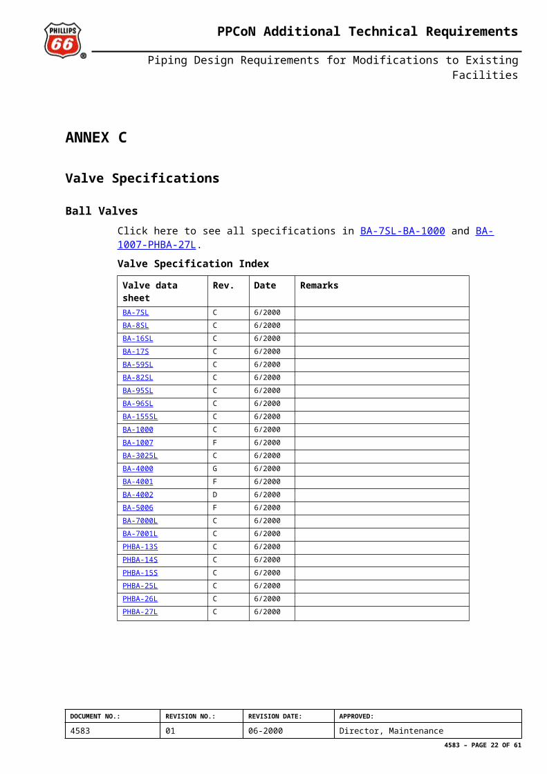
ANNEX C
Valve Specifications
Ball ValvesClick here to see all specifications in BA-7SL-BA-1000 and BA-1007-PHBA-27L.
Valve Specification Index
Valve data sheet Rev. Date RemarksBA - 7SL C 6/2000BA - 8SL C 6/2000BA - 16SL C 6/2000BA - 17S C 6/2000BA - 59SL C 6/2000BA - 82SL C 6/2000BA - 95SL C 6/2000BA - 96SL C 6/2000BA - 155SL C 6/2000BA - 1000 C 6/2000BA-1007 F 6/2000BA - 3025L C 6/2000BA - 4000 G 6/2000BA - 4001 F 6/2000BA - 4002 D 6/2000BA - 5006 F 6/2000BA - 7000L C 6/2000BA - 7001L C 6/2000PHBA - 13S C 6/2000PHBA - 14S C 6/2000PHBA - 15S C 6/2000PHBA - 25L C 6/2000PHBA - 26L C 6/2000PHBA - 27L C 6/2000
DOCUMENT NO.: REVISION NO.: REVISION DATE: APPROVED:
4583 01 06-2000 Director, Maintenance4583 – PAGE 16 OF 52
PPCoN Additional Technical Requirements
Piping Design Requirements for Modifications to Existing Facilities
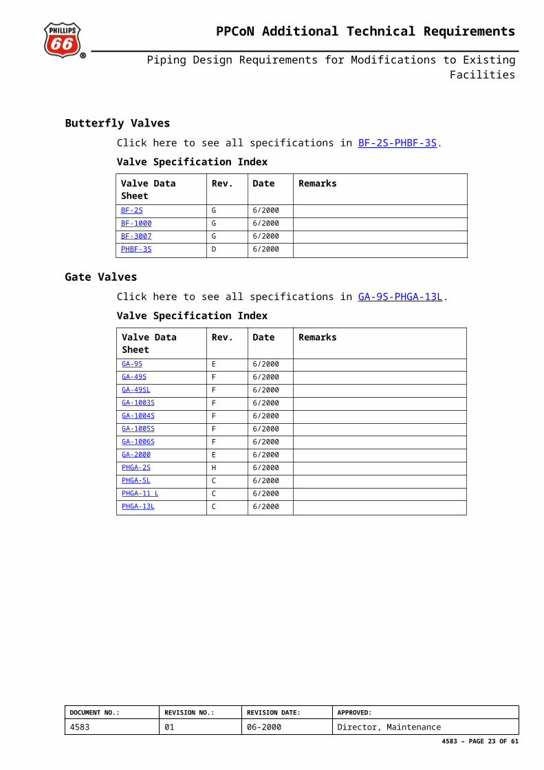
Butterfly ValvesClick here to see all specifications in BF-2S-PHBF-3S.
Valve Specification Index
Valve Data Sheet Rev. Date RemarksBF-2S G 6/2000BF - 1000 G 6/2000BF - 3007 G 6/2000PHBF - 3S D 6/2000
Gate ValvesClick here to see all specifications in GA-9S-PHGA-13L.
Valve Specification Index
Valve Data Sheet Rev. Date RemarksGA - 9S E 6/2000GA - 49S F 6/2000GA - 49SL F 6/2000GA - 1003S F 6/2000GA - 1004S F 6/2000GA - 1005S F 6/2000GA - 1006S F 6/2000GA - 2000 E 6/2000PHGA - 2S H 6/2000PHGA - 5L C 6/2000PHGA - 11 L C 6/2000PHGA - 13L C 6/2000
DOCUMENT NO.: REVISION NO.: REVISION DATE: APPROVED:
4583 01 06-2000 Director, Maintenance4583 – PAGE 17 OF 52
PPCoN Additional Technical Requirements
Piping Design Requirements for Modifications to Existing Facilities
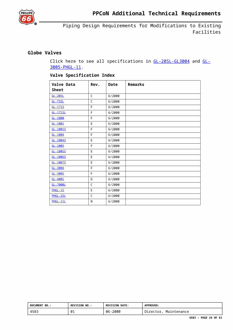
Globe Valves Click here to see all specifications in GL-20SL-GL3004 and GL-3005-PHGL-11.
Valve Specification Index
Valve Data Sheet Rev. Date RemarksGL - 20SL C 6/2000GL - 73SL C 6/2000GL - 171S F 6/2000GL - 171SL F 6/2000GL - 1000 F 6/2000GL - 1001 E 6/2000GL - 1001S F 6/2000GL - 1004 F 6/2000GL - 1004S E 6/2000GL-1005 F 6/2000GL - 1005S E 6/2000GL - 1006S E 6/2000GL - 1007S E 6/2000GL - 3004 F 6/2000GL - 3005 F 6/2000GL - 4001 D 6/2000GL - 7000L C 6/2000PHGL - 1S E 6/2000PHGL - 2SL C 6/2000PHGL-11L N 6/2000
DOCUMENT NO.: REVISION NO.: REVISION DATE: APPROVED:
4583 01 06-2000 Director, Maintenance4583 – PAGE 18 OF 52
PPCoN Additional Technical Requirements
Piping Design Requirements for Modifications to Existing Facilities
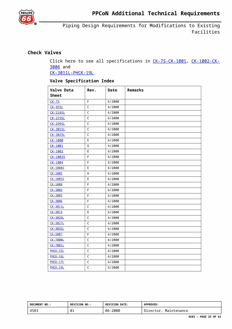
Check ValvesClick here to see all specifications in CK-7S-CK-1001, CK-1002-CK-3006 and CK-3011L-PHCK-19L.
Valve Specification Index
Valve Data Sheet Rev. Date RemarksCK - 7S F 6/2000CK - 95SL C 6/2000CK - 218SL C 6/2000CK - 219SL C 6/2000CK - 299SL C 6/2000CK - 301SL C 6/2000CK - 302SL C 6/2000CK - 1000 E 6/2000CK - 1001 G 6/2000CK - 1002 E 6/2000CK - 1003S F 6/2000CK - 1004 F 6/2000CK - 1004S E 6/2000CK - 1005 H 6/2000CK - 1005S E 6/2000CK - 1008 F 6/2000CK - 3002 F 6/2000CK - 3003 F 6/2000CK - 3006 F 6/2000CK - 3011L C 6/2000CK - 3013 E 6/2000CK - 3026L C 6/2000CK - 3027L C 6/2000CK - 3032L C 6/2000CK - 5007 F 6/2000CK - 7000L C 6/2000CK - 7001L C 6/2000PHCK - 15L C 6/2000PHCK - 16L C 6/2000PHCK - 17L C 6/2000PHCK - 19L C 6/2000
DOCUMENT NO.: REVISION NO.: REVISION DATE: APPROVED:
4583 01 06-2000 Director, Maintenance4583 – PAGE 19 OF 52
PPCoN Additional Technical Requirements
Piping Design Requirements for Modifications to Existing Facilities
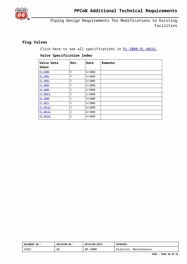
Plug ValvesClick here to see all specifications in PL-3000-PL-4016L.
Valve Specification Index
Valve Data Sheet Rev. Date RemarksPL - 3000 F 6/2000PL - 3001 F 6/2000PL - 4002 C 6/2000PL - 4003 C 6/2000PL - 4006 C 6/2000PL - 4007L C 6/2000PL - 4008 C 6/2000PL - 4011 C 6/2000PL - 4012L C 6/2000PL - 4015L C 6/2000PL - 4016L C 6/2000
DOCUMENT NO.: REVISION NO.: REVISION DATE: APPROVED:
4583 01 06-2000 Director, Maintenance4583 – PAGE 20 OF 52
PPCoN Additional Technical Requirements
Piping Design Requirements for Modifications to Existing Facilities
Notes for Valve RequisitioningC1 ScopeThese notes cover the requisitioning requirements for all manual valves. (For further design and installation information refer to Secion 2.4 Special Applications).
C2 SubstitutionsValve details shall comply with the relevant PPCoN Valve Spec Sheets in this Annex (or in limited instances the “43, 87 or 91 -series” specification sheet, see C3). No substitutions may be made by the Vendor without written agreement from PPCoN.
C3 Non Standard ValvesManual Valves that do not generally comply with the PPCoN Valve Specification Sheets require specific company approval. Any such valve shall be regarded as a “Piping Speciality” and given a ‘87’or’61 -‘ series number. This number is to be shown on the mechanical flowsheet.
Actuated valves (remote operated, non-manual) are purchased as Instrument items category’43’ or’91’for the complete assembly. Separate Instrument specifications are prepared for these actuated valves. In the case of the valve part being identical to a standard manual valve (without wrench etc.) in this appendix, the relevant standard valve specification is to be included in the Instrument specification.
C4 Valve MaterialUnless specifically unrestricted on the PPCoN valve specification sheet, the valve material carbon content for carbon maganese steel valves shall not exceed 0.22% (ladle analysis). If material with 0.22% carbon max. is specified but cannot be obtained, then the use of higher carbon contents shall be subject to approval by the PPCoN Metallurgist.
Note: the 0.22% carbon content limit does not apply for non welded components.
For hydro - carbon and produced water service : Where the valve specifications show valve components in UNS N06600 and N06625, they shall be supplied in the annealed condition or supplied with certification showing that the supplied parts comply with NACE MR0175 requirements. Other UNS N066xx or N077xx alloys are only acceptable with certification showing that the supplied parts comply with NACE MR01 75 requirements.
C5 Valve DimensionsAll flanged valves shall have ASME B 16.5 flange and ASME B 16.10 end to end dimensions where applicable. Butterfly valves that meet API Standard 609 for end to end dimensions are preferred. When replacing existing valves particular attention should be given to checking existing/replacement valve lengths to ensure the valves can be easily exchanged.
C6 Drain Bosses/PlugsUnless specified on the Valve Spec. Sheet, drain bosses on valves shall be supplied untapped. When plugs are specified these shall be solid, NPT threaded and be galvanically compatible and of similar strength as the valve body material.
C7 Ball Valve Seat Injection PointsOn ball valves 300 lb. ANSI and above, 17 n.b. and greater, seat injection points for grease/sealant shall be fitted as follows;
Valve size 17 n.b. to 27 n.b., a minimum of two injection points equally spaced diametrically at the seat in each end of the ball valve (ie. minimum four total).
DOCUMENT NO.: REVISION NO.: REVISION DATE: APPROVED:
4583 01 06-2000 Director, Maintenance4583 – PAGE 21 OF 52
PPCoN Additional Technical Requirements
Piping Design Requirements for Modifications to Existing Facilities
Valve size 24” n.b. and greater, a minimum of four injection points equally spaced diametrically at the seat in each end of the ball valve (ie. minimum eight total).
All grease/seal ant fittings exposed to direct or indirect line pressure shall be as follows:
UNS G41400 (AISI type 4140) material in quenched and tempered condition, when used with carbon steel valves. Fitting material for non-carbon steel valves must be galvanically compatible with the valve material, see reference given in C6.
Style with heaviest wall thickness.
1-/2”, 3/8” and ¼” NPT (Use largest size possible compatible with valve size/design).
Blow out proof buttonhead fittings to be used.
C8 Ball Valve Body Vent/Drain ValvesOn ball valves 300 lb ANSI and above, 12” n.b. and greater, body vent/drain valves shall be fitted as follows;
Valve size 17 n.b. to 27 n.b., a minimum of one combination vent/drain valve.
Valve size 24” n.b. and greater, a minimum of one body drain valve installed on the lowest point and one body vent valve installed on the highest point of the valve body.
Refer to the relevant PPCoN Pipe spec. to determine the PPCoN Valve Spec. to be used for the vent/drain valves. Where size of the main ball valve allows, a flanged drain/vent valve studded directly to the main ball valve is preferred for mechanical strength. The discharge end of the vent/drain valve shall be supplied with a blind flange or NPT plug as relevant.
C9 AluminiumThis material will not be allowed in any part of the valve or valve accessories.
C10 TestingMaterial: Notch_Toughness Tests: Material shall meet Charpy V-notch impact (CVN) test minimum value requirements stated on the applicable MDS.
Welding Notch Toughness Tests: PPCoN shall review and accept the welding procedures and supporting qualification records for all valve fabrication welding. Welding shall meet CVN test minimum value requirements stated in Norok M-601.
Hardness Testing: Pressure retaining parts on valves shall be subject to the hardness requirements in NACE MR0175 when called for on the relevant valve specification sheet.
Pressure Tests: Generally valves shall be pressure tested in accordance with BS 6755 part 1 or API 598. After hydrostatic tests are carried out on assembled valves, test packings and all traces of test media shall be removed from the internal parts and the packings (if any) replaced with unused dry packings.
Operational Tests: All limit stops and open/closed indicators (whether wrench, handwheel or gearbox operation) shall be properly set and checked by the Vendor prior to delivery.
C11 Valve MarkingAll valves: Marking shall be according to MSS-SP-25. Additionally the following marking shall be incorporated:
Manufacturer’s serial no.
VDS identification (eg. GTAC 10R)
The marking shall be made on a stainless steel identification plate permanently fixed to the valve. Plate thickness shall be of minimum 0.4 mm.
DOCUMENT NO.: REVISION NO.: REVISION DATE: APPROVED:
4583 01 06-2000 Director, Maintenance4583 – PAGE 22 OF 52
PPCoN Additional Technical Requirements
Piping Design Requirements for Modifications to Existing Facilities
Marking directly onto the valve body shall be excecuted with low stress stamps. Marking on weld bevels, flange faces or sufaces that will be hidden following fabrication, assembly or installation, is not allowed.
Highly visible flow direction arrows shall be permanently marked on all valves having a required or preferred flow direction (eg: check valves, some ball and butterfly valves etc.)
C12 Valve Exterior FinishThe exterior of corrosion resistant valves (eg: stainless steel, monel, titanium, aluminium-bronze, 25Cr duplex ss, etc.) shall not be painted.
The exterior of carbon steel valves shall be surface treated according to Norsok M-501, system 9. The color shall be white unless otherwise specified.
Machined surfaces of c-steel including gaskets seating surfaces of flanges, threads, ends prepared for welding etc., shall be sprayed or coated with a temporary protective coating. The coating shall be generously applied and resistant to abrasion during handling and shall be readily removable for assembly or welding. Regardless of material, all valve stems (including threads) packing gland crevices and bonnet bolt areas shall be generously coated as described herein.
C13 Nickel PlatingAll electroless nickel plating (ENP) (specified for trim in some valve specifications) shall comply with NORSOK L-001). PPCoN has several negative experiences with ENP coatings and therefore the manufacturers are generally encouraged to propose alternative base materials to avoid coatings or alternative coating systems (e.g. tungsten carbide, stellite, etc.).
C14 Valve End ProtectionThreaded end connections, “hub connectors” etc. and ends prepared for welding shall be fitted with stout plastic cap protectors. Flanged ends shall be sealed at the flanges with stout timber, metal or plastic waterproof covers bolted or taped on the flange. Hardboard material is not acceptable.
C15 PackagingBall and Plug Valves shall be shipped and stored in the “open” position. Butterfly valves shall be shipped and stored with the disc slightly open (in the liner/seat relaxed position). All other valve types to be shipped and stored in the “closed” position unless otherwise agreed between PPCoN and the Vendor.
The Vendors of valves are required to ensure that all materials, when delivered are adequately protected against corrosion and mechanical damage. Protection shall be suitable for a period of at least 2 years as packed and crated (or otherwise to a written schedule of routine checks and rectification).
One set of documentation shall be supplied by the vendor in waterproof packing in the crate/box with the valve(s). The documentation shall be for every valve (or group of valves of similar type), as follows:
Installation, handling, operation and maintenance instructions.
Drawings showing construction, parts, materials etc.
When sufficiently detailed, catalogue information may suffice.
C16 CertificationThe certification is grouped by PPCoN into type I, II and Ill. This grouping is based on criticality (ascending order of criticality). The valve specification defines which certification
DOCUMENT NO.: REVISION NO.: REVISION DATE: APPROVED:
4583 01 06-2000 Director, Maintenance4583 – PAGE 23 OF 52
PPCoN Additional Technical Requirements
Piping Design Requirements for Modifications to Existing Facilities
type (I, II or III) is required. Any valve supplied without the required marking or documentation will be subject to rejection.
Note that for all certification types, valves must be marked, tagged and stamped as defined in C11 and be accompanied by copies of the pressure test certificates.
Otherwise the requirements for each certification type is as follows:
Type I Certification:
Corresponds to EN 10204 type 2.1. These valves have markings required by the applicable standard such as Grade, size, heat no. code, manufacturers indentification, and other required items. Any substitution to the component/material specified on the valve specification (that has been agreed by PPCoN) shall become Type II certification.
Type II Certification:
Corresponds to EN 10204 type 3.1.B.
The production process, welding procedure specifications with procedure qualification records, heat treatment, fire test certificate, and other relevant features, if not limited or described by the specification, shall be included.
Type Ill Certification:
Corresponds to EN 10204 type 3.1.C.This certificate requires that testing of materials be carried out under a PPCoN approved independent Third party’s supervision and must be signed by them. All other requirements for a Type II Certificate apply.
DOCUMENT NO.: REVISION NO.: REVISION DATE: APPROVED:
4583 01 06-2000 Director, Maintenance4583 – PAGE 24 OF 52
PPCoN Additional Technical Requirements
Piping Design Requirements for Modifications to Existing Facilities
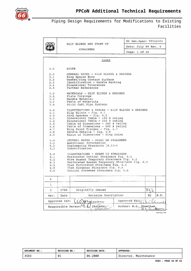
ANNEX D
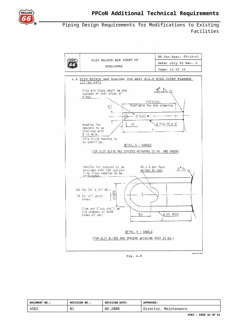
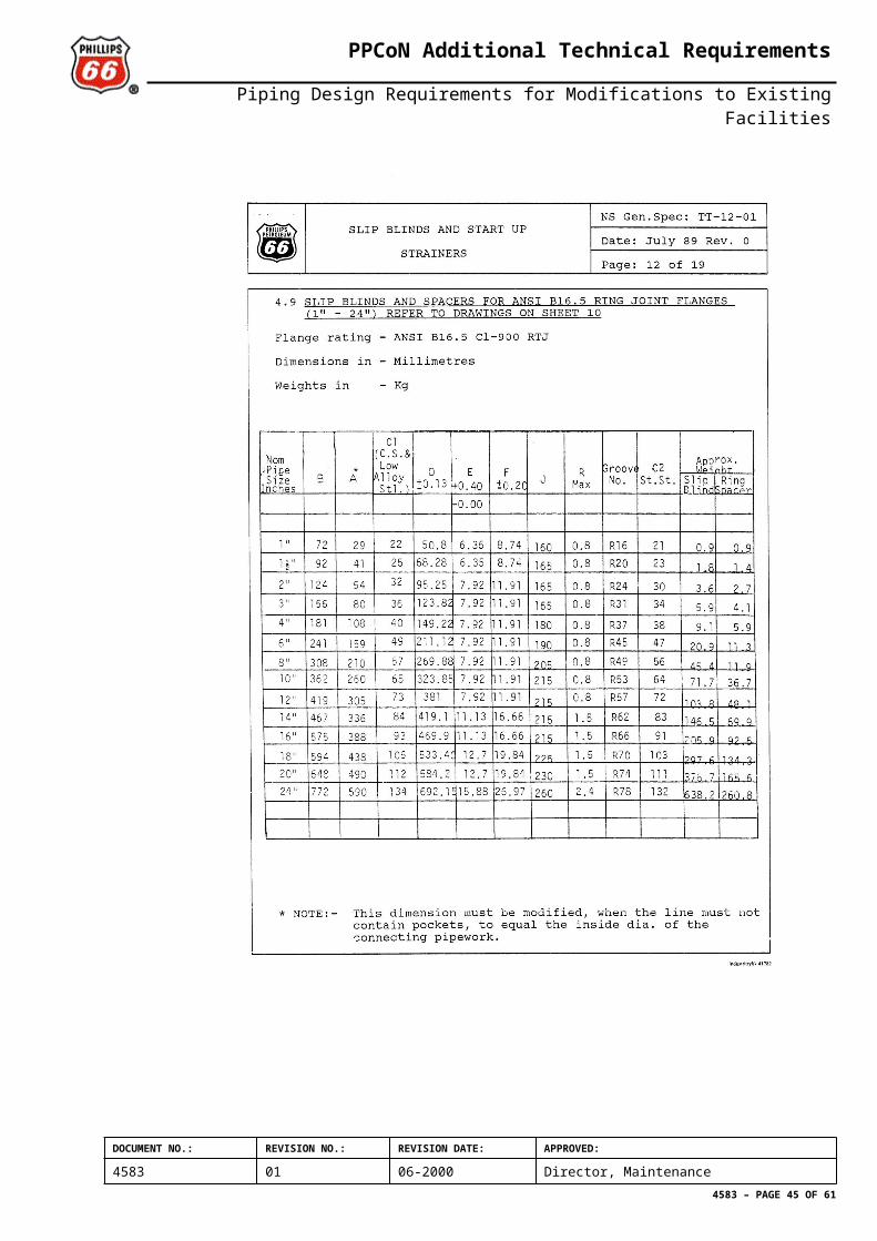
Slip Blinds and Start Up StrainersThe following 19 pages are a scanned copy of TT-12-01 ”Slip Blinds and Start Up Strainers” which shall be used as a guideline when the PPCoN P-specs. are applied. When KE PCS’ or NORSOK PCS’ are applied the EDS’ in KE-P-T-001 and NORSOK L-001 respectively shall be followed.
DOCUMENT NO.: REVISION NO.: REVISION DATE: APPROVED:
4583 01 06-2000 Director, Maintenance4583 – PAGE 25 OF 52
PPCoN Additional Technical Requirements
Piping Design Requirements for Modifications to Existing Facilities
DOCUMENT NO.: REVISION NO.: REVISION DATE: APPROVED:
4583 01 06-2000 Director, Maintenance4583 – PAGE 26 OF 52
PPCoN Additional Technical Requirements
Piping Design Requirements for Modifications to Existing Facilities
DOCUMENT NO.: REVISION NO.: REVISION DATE: APPROVED:
4583 01 06-2000 Director, Maintenance4583 – PAGE 27 OF 52
PPCoN Additional Technical Requirements
Piping Design Requirements for Modifications to Existing Facilities
DOCUMENT NO.: REVISION NO.: REVISION DATE: APPROVED:
4583 01 06-2000 Director, Maintenance4583 – PAGE 28 OF 52
PPCoN Additional Technical Requirements
Piping Design Requirements for Modifications to Existing Facilities
DOCUMENT NO.: REVISION NO.: REVISION DATE: APPROVED:
4583 01 06-2000 Director, Maintenance4583 – PAGE 29 OF 52
PPCoN Additional Technical Requirements
Piping Design Requirements for Modifications to Existing Facilities
DOCUMENT NO.: REVISION NO.: REVISION DATE: APPROVED:
4583 01 06-2000 Director, Maintenance4583 – PAGE 30 OF 52
PPCoN Additional Technical Requirements
Piping Design Requirements for Modifications to Existing Facilities
DOCUMENT NO.: REVISION NO.: REVISION DATE: APPROVED:
4583 01 06-2000 Director, Maintenance4583 – PAGE 31 OF 52
PPCoN Additional Technical Requirements
Piping Design Requirements for Modifications to Existing Facilities
DOCUMENT NO.: REVISION NO.: REVISION DATE: APPROVED:
4583 01 06-2000 Director, Maintenance4583 – PAGE 32 OF 52
PPCoN Additional Technical Requirements
Piping Design Requirements for Modifications to Existing Facilities
DOCUMENT NO.: REVISION NO.: REVISION DATE: APPROVED:
4583 01 06-2000 Director, Maintenance4583 – PAGE 33 OF 52
PPCoN Additional Technical Requirements
Piping Design Requirements for Modifications to Existing Facilities
DOCUMENT NO.: REVISION NO.: REVISION DATE: APPROVED:
4583 01 06-2000 Director, Maintenance4583 – PAGE 34 OF 52
PPCoN Additional Technical Requirements
Piping Design Requirements for Modifications to Existing Facilities
DOCUMENT NO.: REVISION NO.: REVISION DATE: APPROVED:
4583 01 06-2000 Director, Maintenance4583 – PAGE 35 OF 52
PPCoN Additional Technical Requirements
Piping Design Requirements for Modifications to Existing Facilities
DOCUMENT NO.: REVISION NO.: REVISION DATE: APPROVED:
4583 01 06-2000 Director, Maintenance4583 – PAGE 36 OF 52
PPCoN Additional Technical Requirements
Piping Design Requirements for Modifications to Existing Facilities
DOCUMENT NO.: REVISION NO.: REVISION DATE: APPROVED:
4583 01 06-2000 Director, Maintenance4583 – PAGE 37 OF 52
PPCoN Additional Technical Requirements
Piping Design Requirements for Modifications to Existing Facilities
DOCUMENT NO.: REVISION NO.: REVISION DATE: APPROVED:
4583 01 06-2000 Director, Maintenance4583 – PAGE 38 OF 52
PPCoN Additional Technical Requirements
Piping Design Requirements for Modifications to Existing Facilities
DOCUMENT NO.: REVISION NO.: REVISION DATE: APPROVED:
4583 01 06-2000 Director, Maintenance4583 – PAGE 39 OF 52
PPCoN Additional Technical Requirements
Piping Design Requirements for Modifications to Existing Facilities
DOCUMENT NO.: REVISION NO.: REVISION DATE: APPROVED:
4583 01 06-2000 Director, Maintenance4583 – PAGE 40 OF 52
PPCoN Additional Technical Requirements
Piping Design Requirements for Modifications to Existing Facilities
DOCUMENT NO.: REVISION NO.: REVISION DATE: APPROVED:
4583 01 06-2000 Director, Maintenance4583 – PAGE 41 OF 52
PPCoN Additional Technical Requirements
Piping Design Requirements for Modifications to Existing Facilities
DOCUMENT NO.: REVISION NO.: REVISION DATE: APPROVED:
4583 01 06-2000 Director, Maintenance4583 – PAGE 42 OF 52
PPCoN Additional Technical Requirements
Piping Design Requirements for Modifications to Existing Facilities
DOCUMENT NO.: REVISION NO.: REVISION DATE: APPROVED:
4583 01 06-2000 Director, Maintenance4583 – PAGE 43 OF 52
PPCoN Additional Technical Requirements
Piping Design Requirements for Modifications to Existing Facilities
DOCUMENT NO.: REVISION NO.: REVISION DATE: APPROVED:
4583 01 06-2000 Director, Maintenance4583 – PAGE 44 OF 52
PPCoN Additional Technical Requirements
Piping Design Requirements for Modifications to Existing Facilities
ANNEX E
Variations In Design PrinciplesSome principal technical differences between NSDP/original design pipe specifications and NORSOK are given herein. Other differences than those described may occur.
FlangesPPCoN P-specs have RF flanges in the following pressure classes: 150, 300, 600. P-specs have RTJ flanges in the following pressure classes: 900, 1500, 2500. Note: P903, P2502 & P2510 and most original design specifications in cl.900 (eg. '901') also use RF flanges.
Norsok PCS’ have RF flanges in the following pressure classes: 150 & 300. Norsok PCS’ have RTJ flanges in the following pressure classes: 600, 900, 1500 & 2500.
GasketsP-specs and Eko II specs with RF flanges generally use 3.2mm thick spiral wound gaskets with outer ring and sometimes also centring ring. One exception is P301 L using 1.6mm flat gasket to ASME B16.21.
P-specs with RTJ flanges generally use octagonal soft iron rings. Exception is P3001 which use oval soft iron ring.
PCS's with RF flanges generally use 1.5mm flat gasket to ASME B16.21.
PCS's with RTJ flanges allow the use of both oval and octagonal rings in various material qualities, see individual PCS's for details.
HubsP-specs with hub connections have other wall thickness than comparable PCS's. This gives conflicting hub sizes, which prevent automatic interchangeability of high pressure pipe specifications with clamped connections.ASME class 1500 2500
P-spec 4GR34 (P1501) 4GR25 (P2501 L)
PCS 4GR31 (FC15) 4GR27 (GC15)
Table E. 1: Hubconnections 4 in. nom, bore
In addition, it should be noted that some platforms (eg. 2/4A, 2/4C, 2/4W, 2/7D and others) do use clamp connectors not being interchangeable with 'Graylock'. For tie-ins to existing systems, existing construction drawings must be reviewed.
DOCUMENT NO.: REVISION NO.: REVISION DATE: APPROVED:
4583 01 06-2000 Director, Maintenance4583 – PAGE 45 OF 52
PPCoN Additional Technical Requirements
Piping Design Requirements for Modifications to Existing Facilities
Nipples/fittingsP-specs generally prescribe the use of socket weld nipples. Threaded nipples are also acceptable, but not recommended. Nipple schedule is XXS or 160. ASME B16.11 is referred for dimensions.
PCS's do not allow the use of socket welded branches or nipples. Nipple schedule is 80, 160 or XXS, depending on pipe material and rating. ASME B16.9 is referred for butt welded fittings. Threaded components are only acceptable in branches d/s of a butt welded isolation valve.
Valve face to face dimensionsP-specs generally follow ASME B16.10 and API 6D for face to face dimensions for valves. Butterfly valves have face to face dimensions according to API 609, table 1.
PCS's generally follow ASME B16.10 (or API 6D) for face to face dimensions for valves. Butterfly valves have face to face dimensions to API 609, table 2 or BS5155.
Note: several existing PPCoN facilities have special valve face to face dimensions. For correct dimensions, reference is made to PPCoN guideline: GL-4D-12-04.
DOCUMENT NO.: REVISION NO.: REVISION DATE: APPROVED:
4583 01 06-2000 Director, Maintenance4583 – PAGE 46 OF 52