Embed Size (px)
Citation preview
© 2007 ASHRAE Hong Kong Chapter Slide 1
Fundamentals of Water System Design
17, 18, 24, 25 January 2007
ASHRAE Hong Kong Chapter Technical Workshop
© 2007 ASHRAE Hong Kong Chapter Slide 2
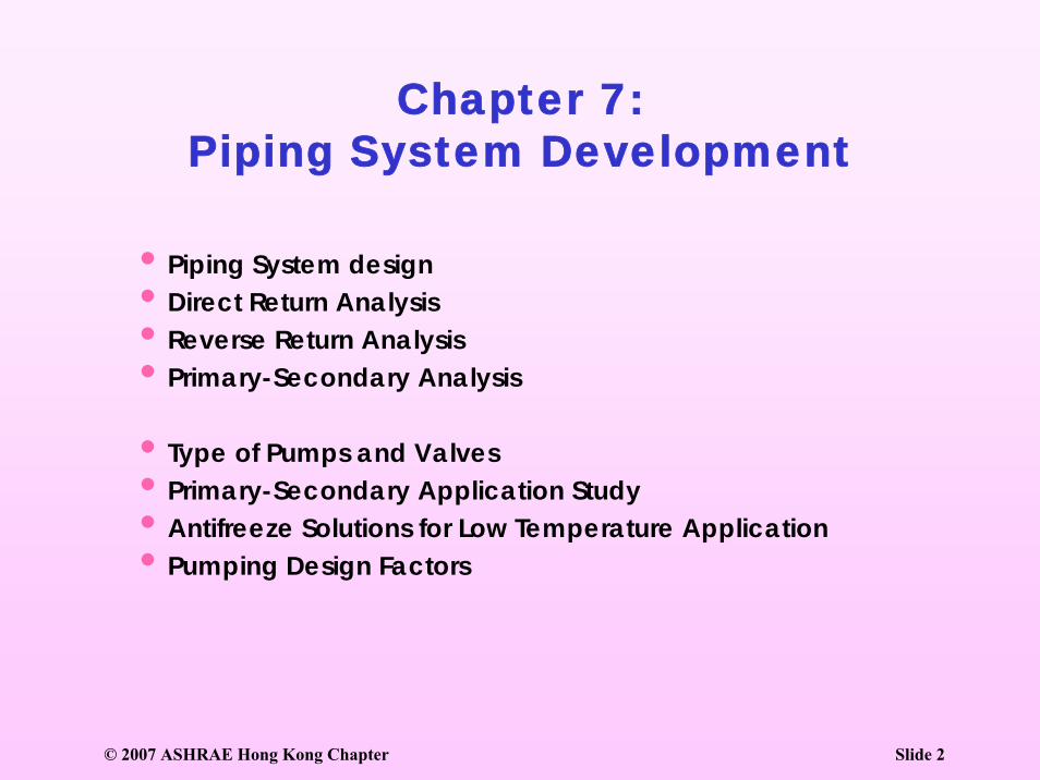
Chapter 7:Piping System Development
•Piping System design•Direct Return Analysis•Reverse Return Analysis•Primary-Secondary Analysis
•Type of Pumps and Valves•Primary-Secondary Application Study•Antifreeze Solutions for Low Temperature Application•Pumping Design Factors
© 2007 ASHRAE Hong Kong Chapter Slide 3
Piping System Design
© 2007 ASHRAE Hong Kong Chapter Slide 4
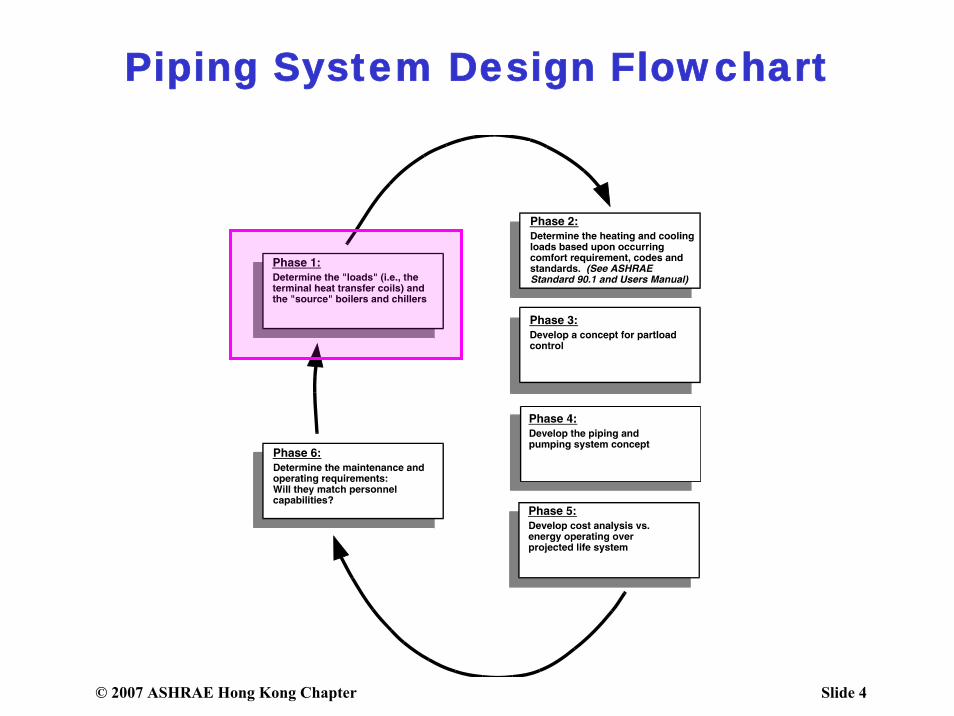
Piping System Design Flowchart
© 2007 ASHRAE Hong Kong Chapter Slide 5
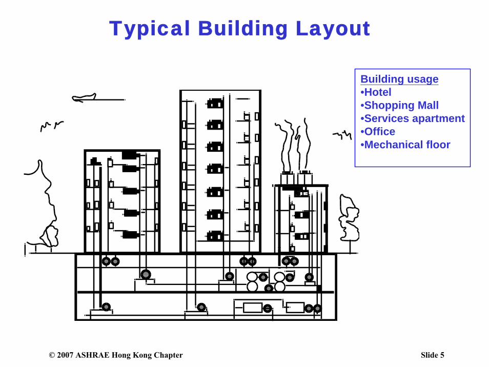
Typical Building Layout
Building usage•Hotel •Shopping Mall•Services apartment•Office•Mechanical floor
© 2007 ASHRAE Hong Kong Chapter Slide 6
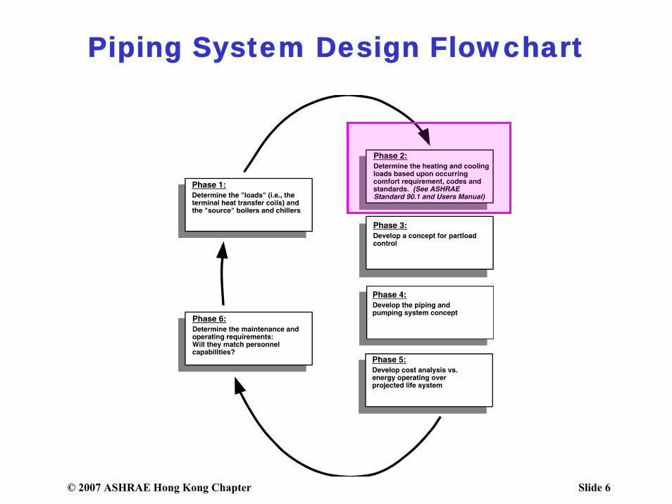
Piping System Design Flowchart
© 2007 ASHRAE Hong Kong Chapter Slide 7
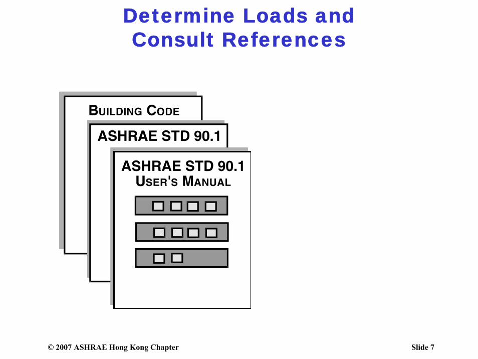
Determine Loads andConsult References
© 2007 ASHRAE Hong Kong Chapter Slide 8
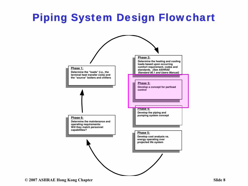
Piping System Design Flowchart
© 2007 ASHRAE Hong Kong Chapter Slide 9
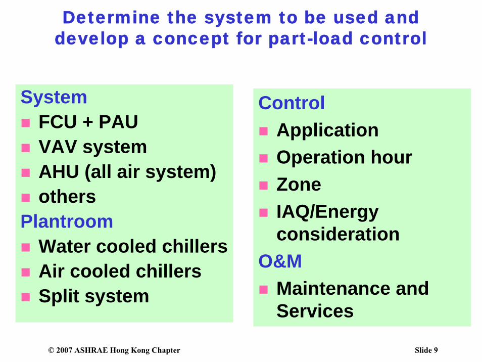
Determine the system to be used and develop a concept for part-load control
SystemFCU + PAUVAV systemAHU (all air system)others
PlantroomWater cooled chillersAir cooled chillersSplit system
ControlApplicationOperation hourZoneIAQ/Energy consideration
O&MMaintenance and Services
© 2007 ASHRAE Hong Kong Chapter Slide 10
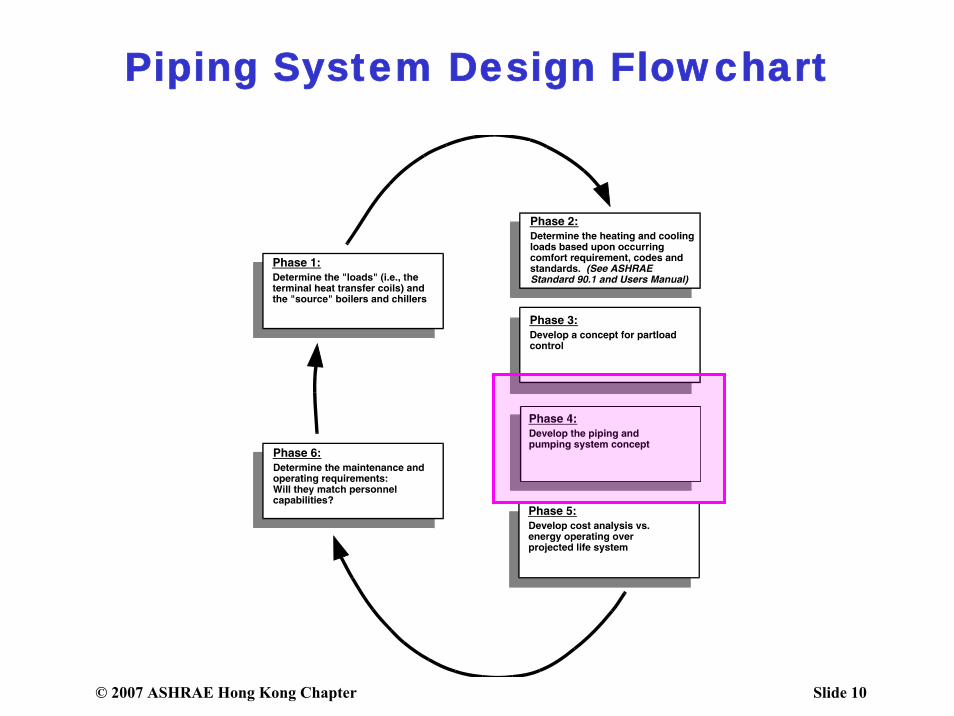
Piping System Design Flowchart

© 2007 ASHRAE Hong Kong Chapter Slide 11
Develop Piping/PumpingSystem Concept
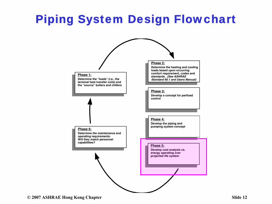
Chiller combination• Full load/Part load/• Emergency• Standby
Pumping system• Primary –Secondary• Variable Primary sys
Water distribution system• Direct return• Reverse return• Direct + reverse return
© 2007 ASHRAE Hong Kong Chapter Slide 12
Piping System Design Flowchart
© 2007 ASHRAE Hong Kong Chapter Slide 13
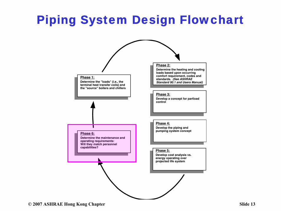
Piping System Design Flowchart
© 2007 ASHRAE Hong Kong Chapter Slide 14
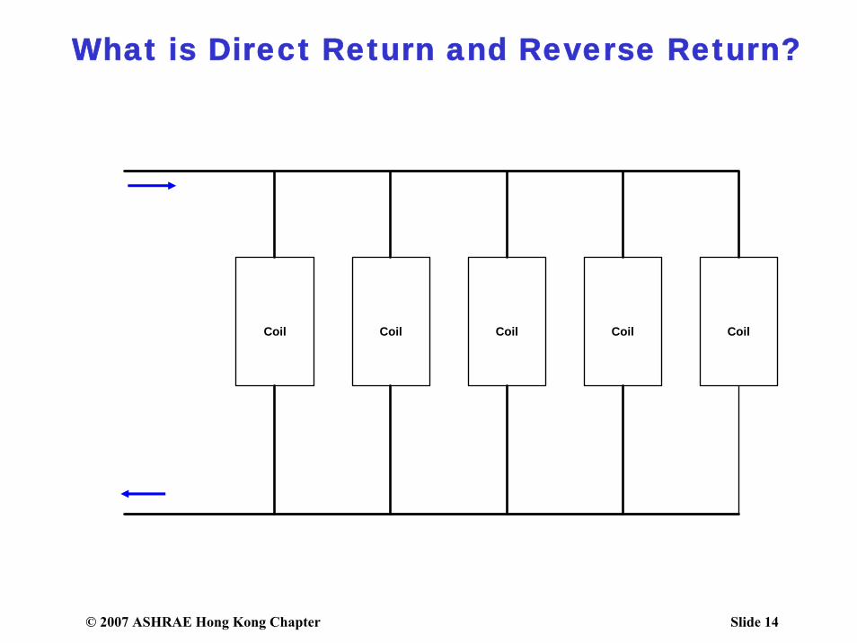
What is Direct Return and Reverse Return?
Coil Coil Coil Coil Coil
© 2007 ASHRAE Hong Kong Chapter Slide 15
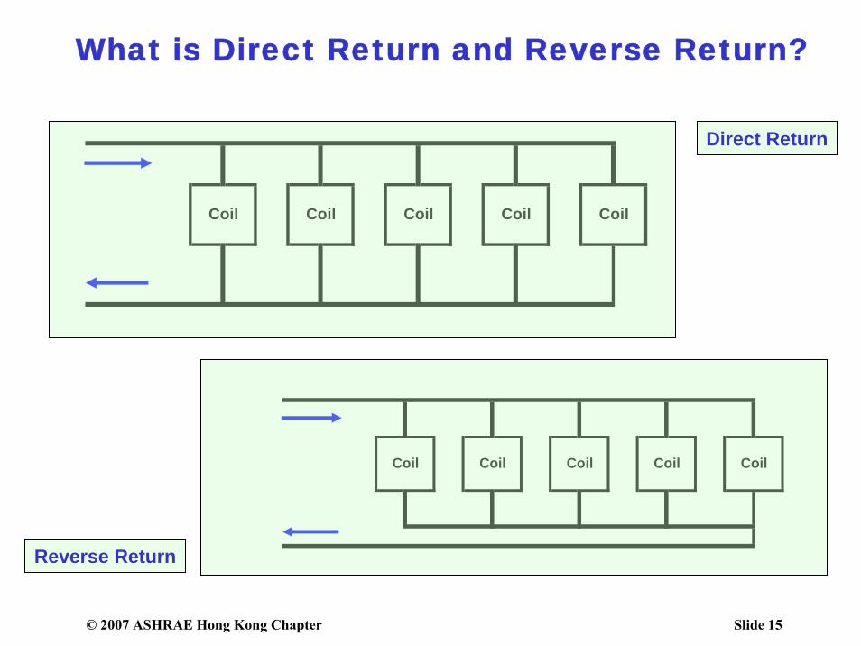
What is Direct Return and Reverse Return?
CoilCoil Coil Coil Coil
CoilCoil Coil Coil Coil
Direct Return
Reverse Return
© 2007 ASHRAE Hong Kong Chapter Slide 16
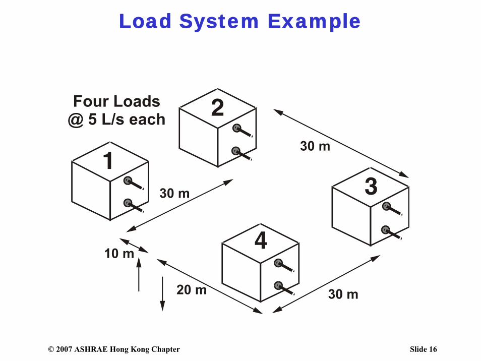
Load System Example
© 2007 ASHRAE Hong Kong Chapter Slide 17
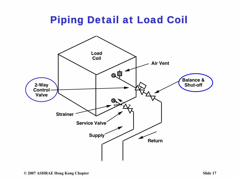
Piping Detail at Load Coil
© 2007 ASHRAE Hong Kong Chapter Slide 18
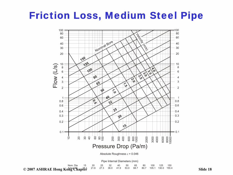
Friction Loss, Medium Steel Pipe
© 2007 ASHRAE Hong Kong Chapter Slide 19
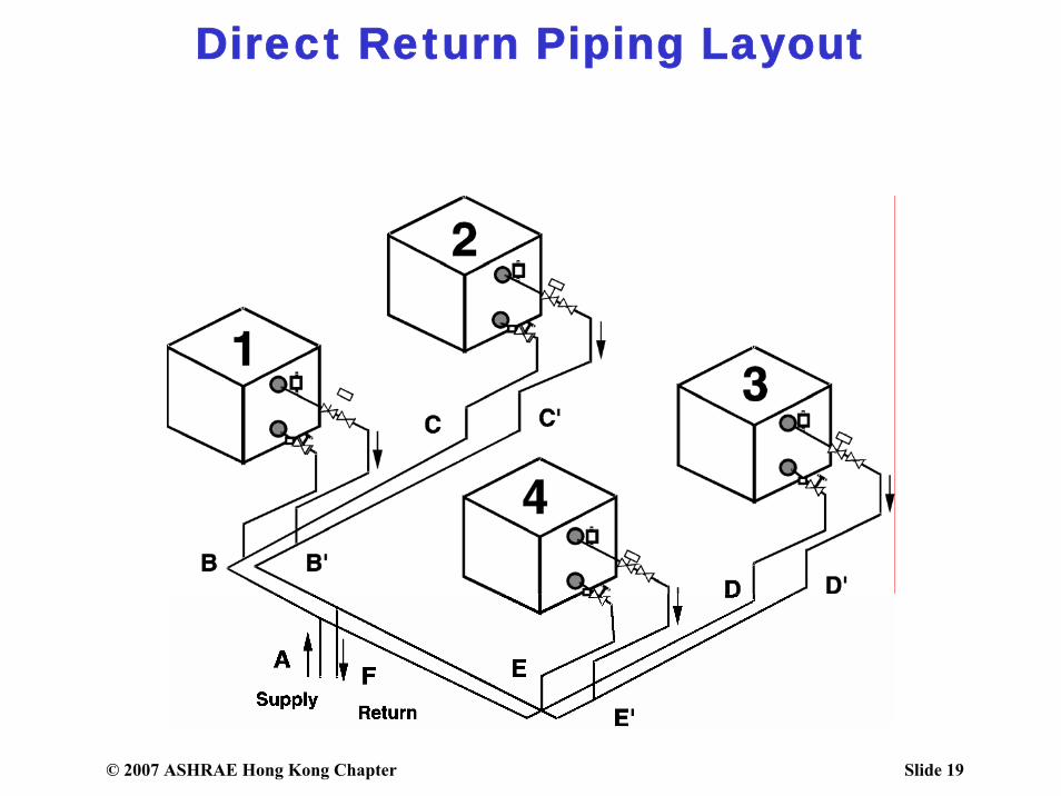
Direct Return Piping Layout
© 2007 ASHRAE Hong Kong Chapter Slide 20
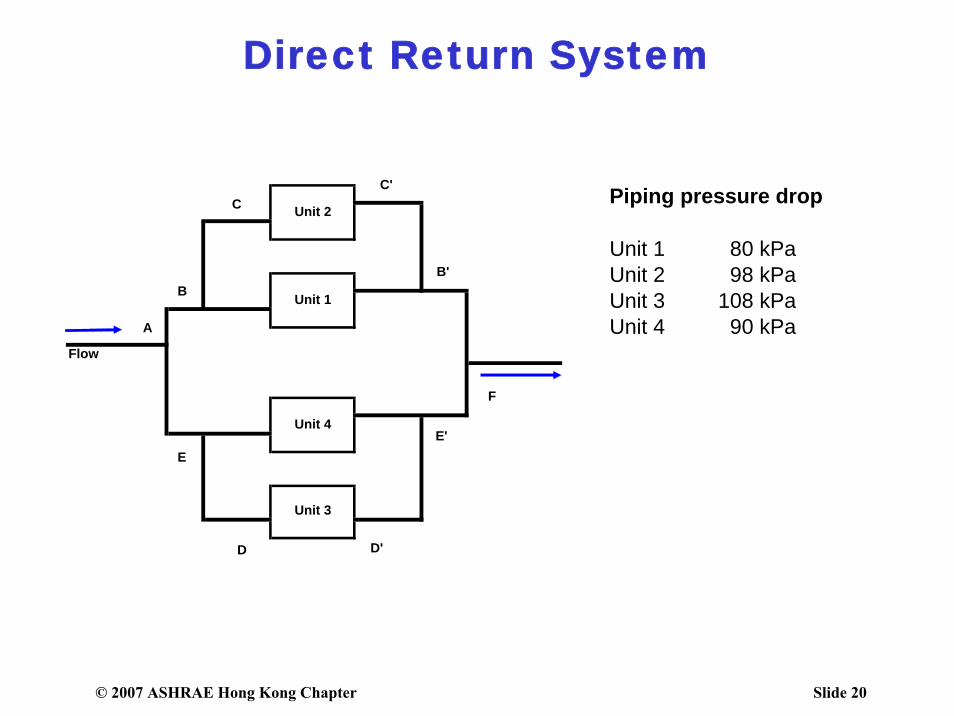
Direct Return System
Flow
Unit 3
Unit 1
Unit 2
Unit 4
A
BB'
CC'
D D'
EE'
F
Piping pressure drop
Unit 1 80 kPaUnit 2 98 kPaUnit 3 108 kPaUnit 4 90 kPa
© 2007 ASHRAE Hong Kong Chapter Slide 21
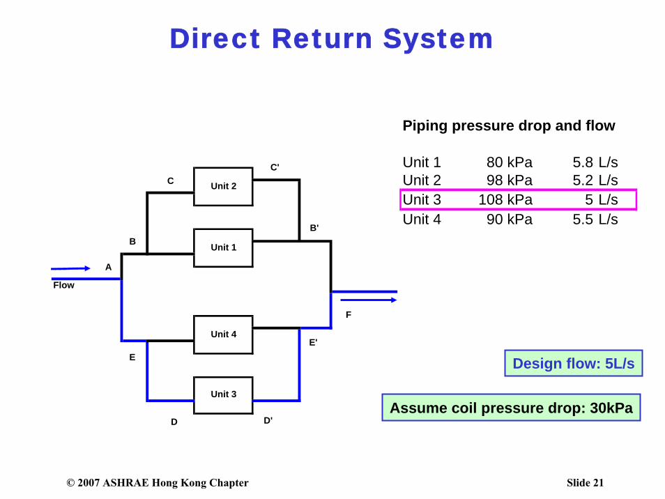
Direct Return System
Flow
Unit 3
Unit 1
Unit 2
Unit 4
A
BB'
CC'
D D'
EE'
F
Piping pressure drop and flow
Unit 1 80 kPa 5.8 L/sUnit 2 98 kPa 5.2 L/sUnit 3 108 kPa 5 L/sUnit 4 90 kPa 5.5 L/s
Design flow: 5L/s
Assume coil pressure drop: 30kPa

© 2007 ASHRAE Hong Kong Chapter Slide 22
Direct Return System
Flow
Unit 3
Unit 1
Unit 2
Unit 4
A
BB'
CC'
D D'
EE'
F
Design flow: 5L/s
Assume coil pressure drop: 15kPa
Piping pressure drop and flow
Unit 1 65 kPa 6 L/sUnit 2 83 kPa 5.3 L/sUnit 3 93 kPa 5 L/sUnit 4 75 kPa 5.6 L/s
© 2007 ASHRAE Hong Kong Chapter Slide 23
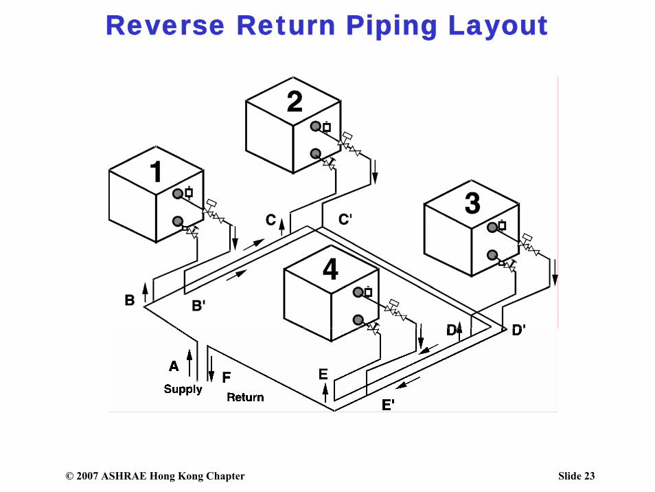
Reverse Return Piping Layout
© 2007 ASHRAE Hong Kong Chapter Slide 24
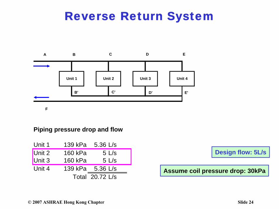
Reverse Return System
Unit 4Unit 1 Unit 2 Unit 3
A B C D E
F
B' C' D' E'
Piping pressure drop and flow
Unit 1 139 kPa 5.36 L/sUnit 2 160 kPa 5 L/sUnit 3 160 kPa 5 L/sUnit 4 139 kPa 5.36 L/s
Total 20.72 L/s
Design flow: 5L/s
Assume coil pressure drop: 30kPa
© 2007 ASHRAE Hong Kong Chapter Slide 25
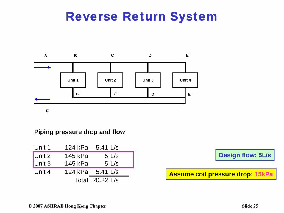
Reverse Return System
Unit 4Unit 1 Unit 2 Unit 3
A B C D E
F
B' C' D' E'
Design flow: 5L/s
Piping pressure drop and flow
Unit 1 124 kPa 5.41 L/sUnit 2 145 kPa 5 L/sUnit 3 145 kPa 5 L/sUnit 4 124 kPa 5.41 L/s
Total 20.82 L/sAssume coil pressure drop: 15kPa
© 2007 ASHRAE Hong Kong Chapter Slide 26
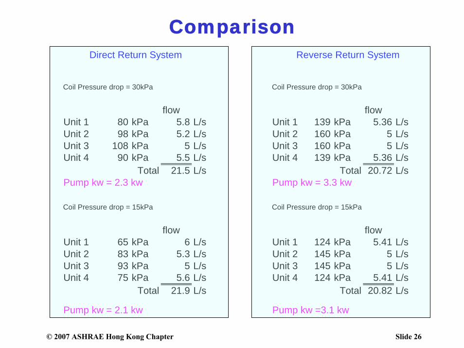
Comparison
Coil Pressure drop = 30kPa Coil Pressure drop = 30kPa
flow flowUnit 1 80 kPa 5.8 L/s Unit 1 139 kPa 5.36 L/sUnit 2 98 kPa 5.2 L/s Unit 2 160 kPa 5 L/sUnit 3 108 kPa 5 L/s Unit 3 160 kPa 5 L/sUnit 4 90 kPa 5.5 L/s Unit 4 139 kPa 5.36 L/s
Total 21.5 L/s Total 20.72 L/sPump kw = 2.3 kw Pump kw = 3.3 kw
Coil Pressure drop = 15kPa Coil Pressure drop = 15kPa
flow flowUnit 1 65 kPa 6 L/s Unit 1 124 kPa 5.41 L/sUnit 2 83 kPa 5.3 L/s Unit 2 145 kPa 5 L/sUnit 3 93 kPa 5 L/s Unit 3 145 kPa 5 L/sUnit 4 75 kPa 5.6 L/s Unit 4 124 kPa 5.41 L/s
Total 21.9 L/s Total 20.82 L/s
Pump kw = 2.1 kw Pump kw =3.1 kw
Direct Return System Reverse Return System
© 2007 ASHRAE Hong Kong Chapter Slide 27
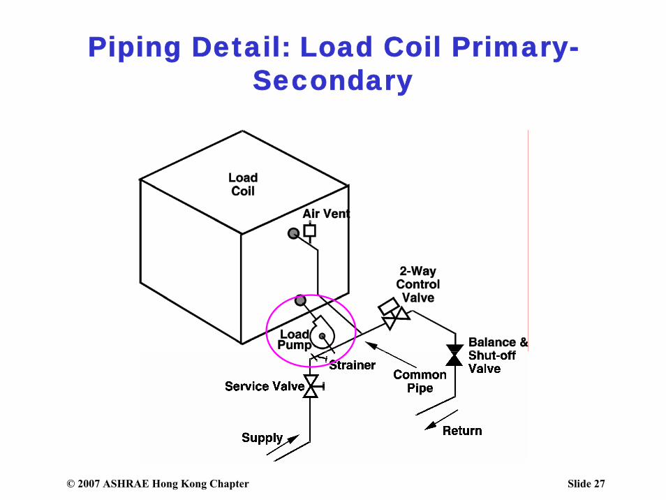
Piping Detail: Load Coil Primary-Secondary
© 2007 ASHRAE Hong Kong Chapter Slide 28
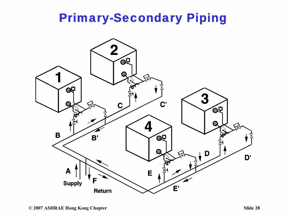
Primary-Secondary Piping
© 2007 ASHRAE Hong Kong Chapter Slide 29
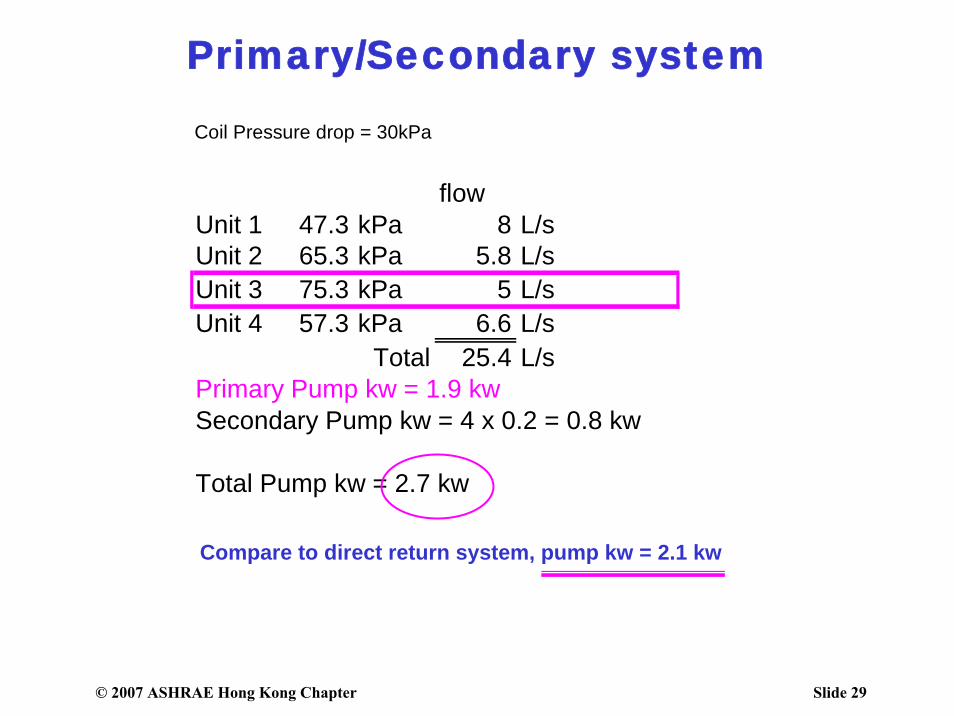
Primary/Secondary system
Coil Pressure drop = 30kPa
flowUnit 1 47.3 kPa 8 L/sUnit 2 65.3 kPa 5.8 L/sUnit 3 75.3 kPa 5 L/sUnit 4 57.3 kPa 6.6 L/s
Total 25.4 L/sPrimary Pump kw = 1.9 kwSecondary Pump kw = 4 x 0.2 = 0.8 kw
Total Pump kw = 2.7 kw
Compare to direct return system, pump kw = 2.1 kw
© 2007 ASHRAE Hong Kong Chapter Slide 30
Purpose of Pumping Systems
Transport sufficient water through the piping system
at the minimum differential pressurethat will satisfy all connected loads at
different load conditions
© 2007 ASHRAE Hong Kong Chapter Slide 31
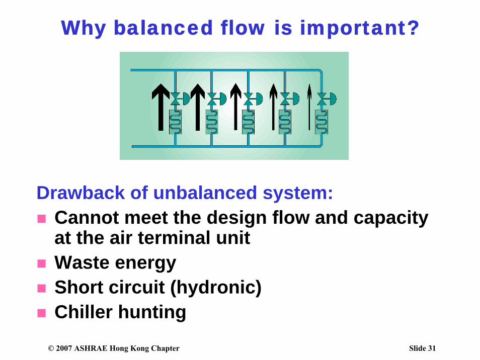
Why balanced flow is important?
Drawback of unbalanced system: Cannot meet the design flow and capacity at the air terminal unit Waste energyShort circuit (hydronic)Chiller hunting
© 2007 ASHRAE Hong Kong Chapter Slide 32
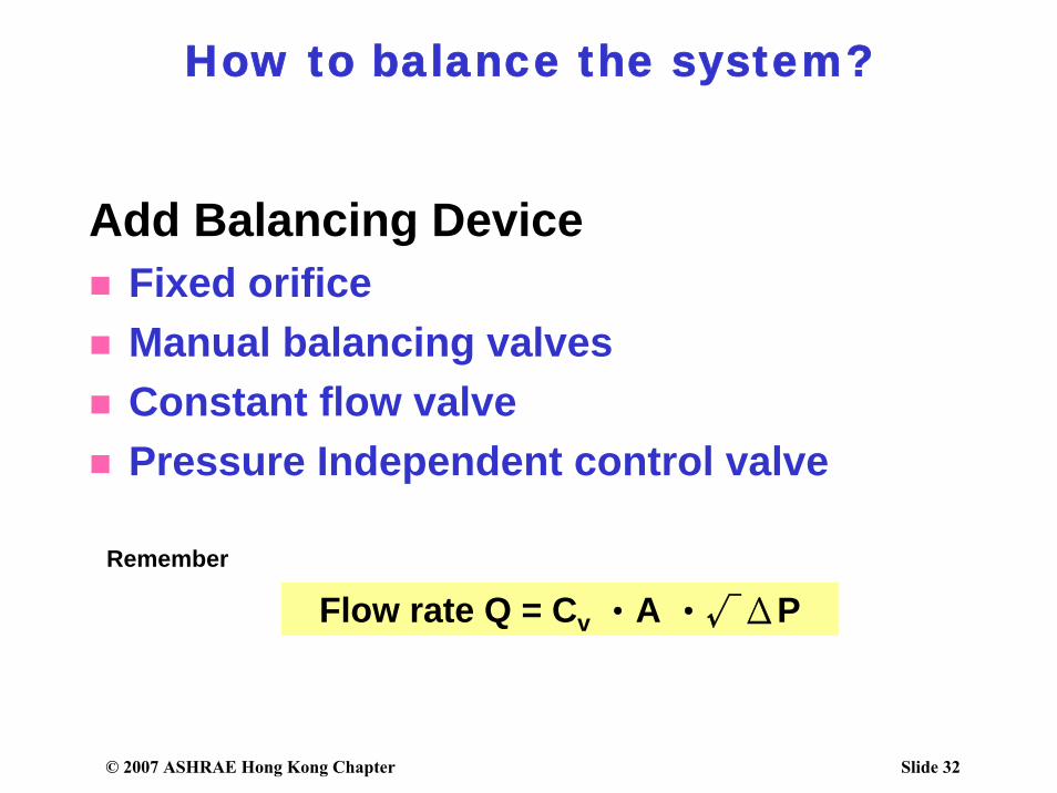
How to balance the system?
Add Balancing DeviceFixed orificeManual balancing valvesConstant flow valve Pressure Independent control valve
Remember
Flow rate Q = Cv ‧A ‧√ΔP
© 2007 ASHRAE Hong Kong Chapter Slide 33
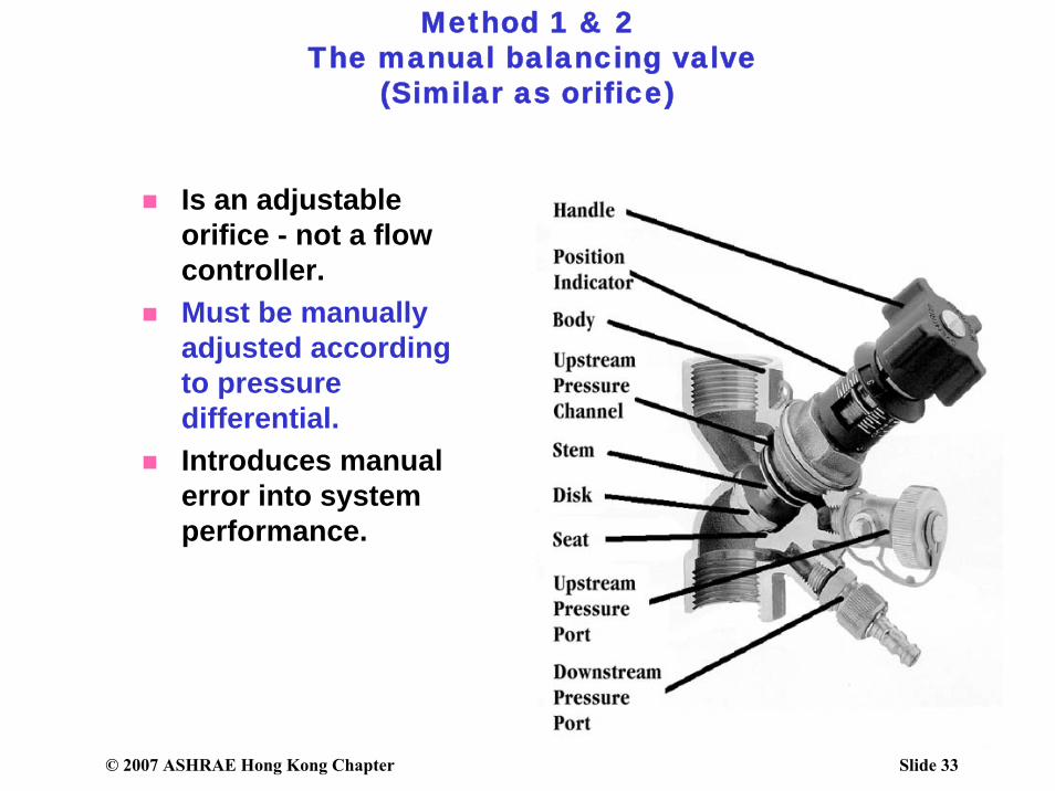
Method 1 & 2The manual balancing valve
(Similar as orifice)
Is an adjustable orifice - not a flow controller.Must be manually adjusted according to pressure differential.Introduces manual error into system performance.
© 2007 ASHRAE Hong Kong Chapter Slide 34
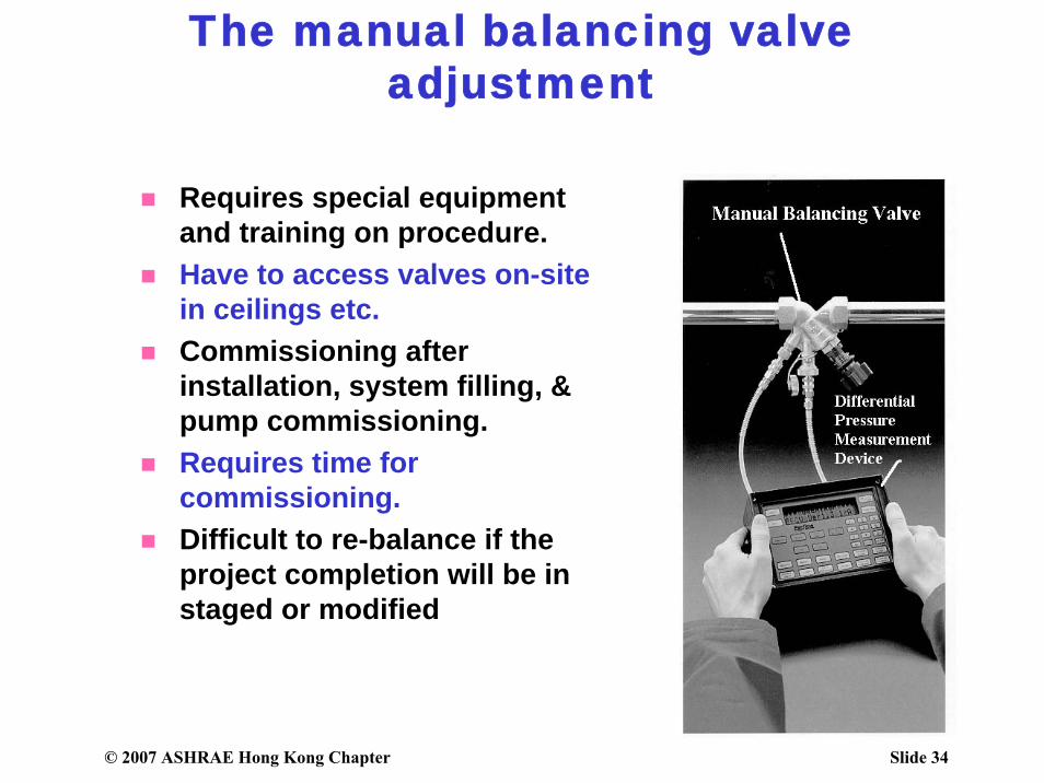
The manual balancing valve adjustment
Requires special equipment and training on procedure.Have to access valves on-site in ceilings etc. Commissioning after installation, system filling, & pump commissioning.Requires time for commissioning.Difficult to re-balance if the project completion will be in staged or modified
© 2007 ASHRAE Hong Kong Chapter Slide 35
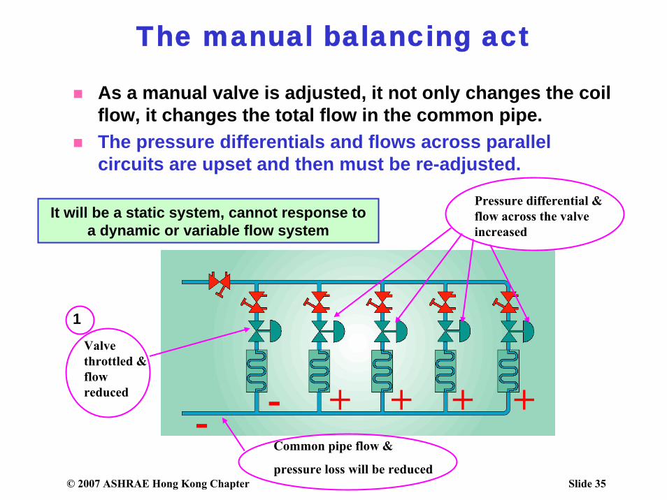
The manual balancing act
As a manual valve is adjusted, it not only changes the coil flow, it changes the total flow in the common pipe. The pressure differentials and flows across parallel circuits are upset and then must be re-adjusted.
- +- + + +
Valve throttled & flow reduced
Common pipe flow &
pressure loss will be reduced
Pressure differential & flow across the valve increased
1
It will be a static system, cannot response to a dynamic or variable flow system
© 2007 ASHRAE Hong Kong Chapter Slide 36
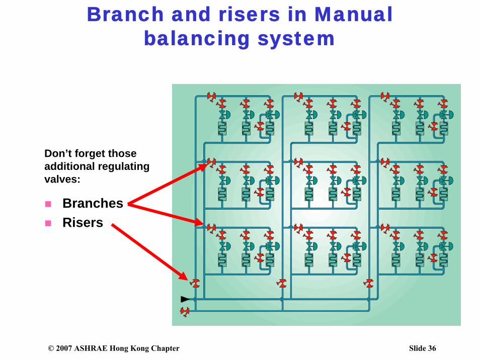
BranchesRisers
Branch and risers in Manual balancing system
Don’t forget those additional regulating valves:
© 2007 ASHRAE Hong Kong Chapter Slide 37
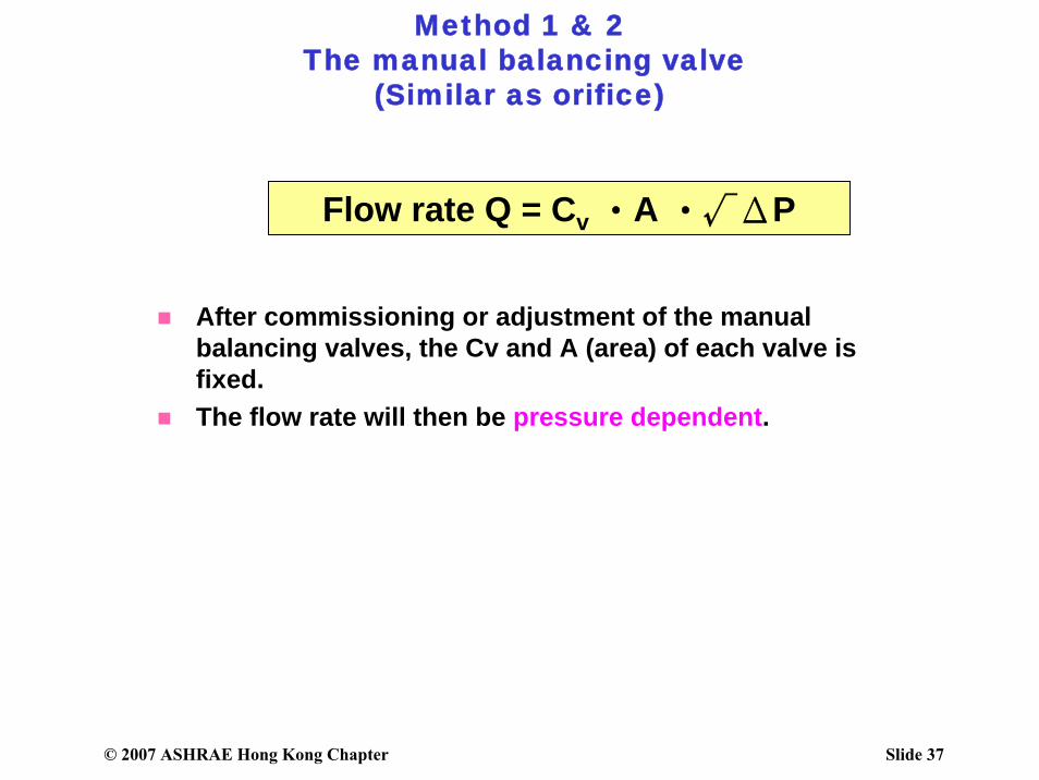
Method 1 & 2The manual balancing valve
(Similar as orifice)
After commissioning or adjustment of the manual balancing valves, the Cv and A (area) of each valve is fixed.The flow rate will then be pressure dependent.
Flow rate Q = Cv ‧A ‧√ΔP
© 2007 ASHRAE Hong Kong Chapter Slide 38
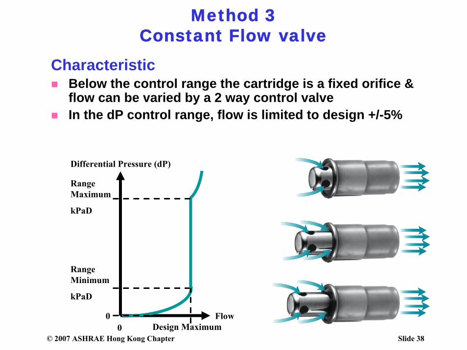
Method 3Constant Flow valve
CharacteristicBelow the control range the cartridge is a fixed orifice & flow can be varied by a 2 way control valve In the dP control range, flow is limited to design +/-5%
Flow
Differential Pressure (dP)
Range Minimum
kPaD
Design Maximum
Range Maximum
kPaD
00
© 2007 ASHRAE Hong Kong Chapter Slide 39
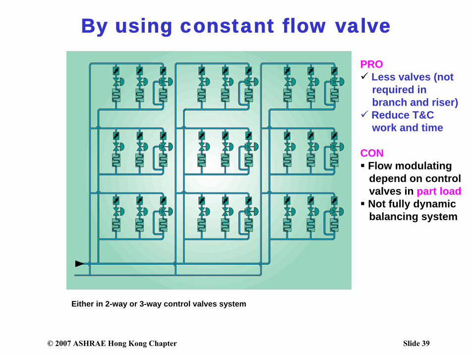
By using constant flow valve
Either in 2-way or 3-way control valves system
PROLess valves (not required in branch and riser)Reduce T&Cwork and time
CONFlow modulating depend on control valves in part loadNot fully dynamic balancing system
© 2007 ASHRAE Hong Kong Chapter Slide 40
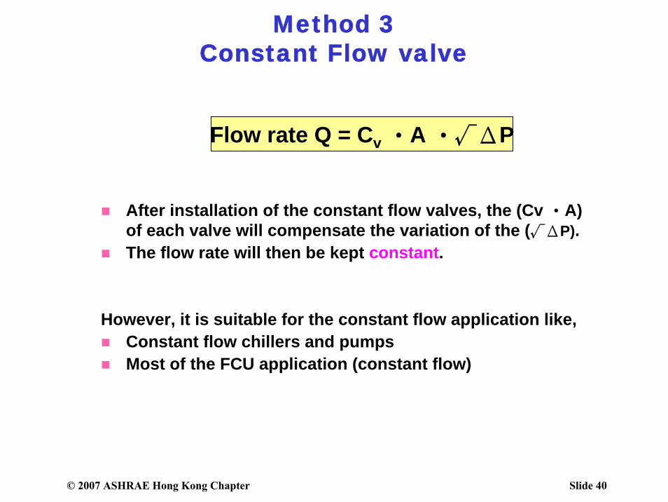
Method 3Constant Flow valve
After installation of the constant flow valves, the (Cv ‧A)of each valve will compensate the variation of the (√ΔP).The flow rate will then be kept constant.
However, it is suitable for the constant flow application like,Constant flow chillers and pumpsMost of the FCU application (constant flow)
Flow rate Q = Cv ‧A ‧√ΔP
© 2007 ASHRAE Hong Kong Chapter Slide 41
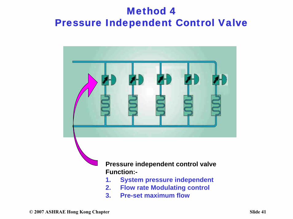
Method 4Pressure Independent Control Valve
Pressure independent control valveFunction:-1. System pressure independent2. Flow rate Modulating control3. Pre-set maximum flow
© 2007 ASHRAE Hong Kong Chapter Slide 42
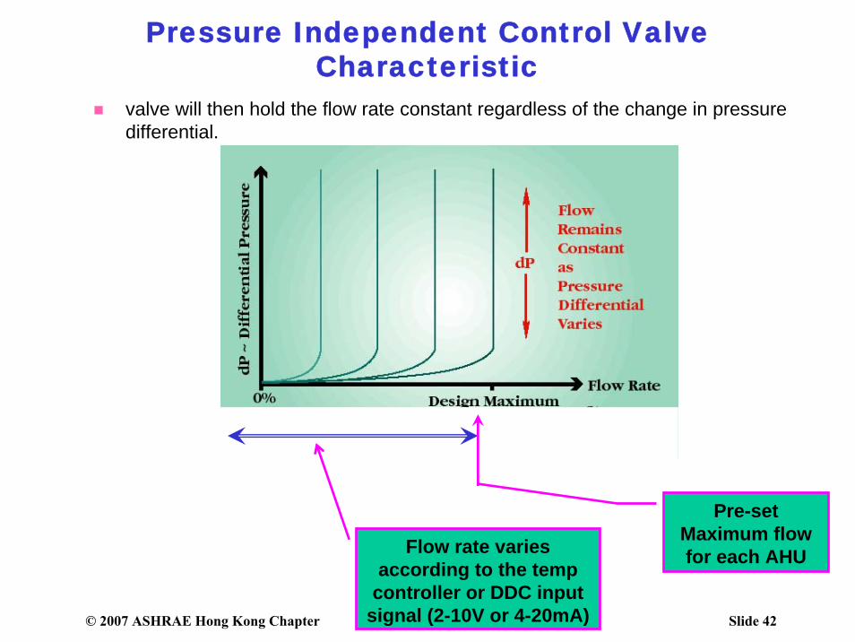
Pressure Independent Control Valve Characteristic
Pre-set Maximum flow for each AHUFlow rate varies
according to the temp controller or DDC input
signal (2-10V or 4-20mA)
valve will then hold the flow rate constant regardless of the change in pressure differential.
© 2007 ASHRAE Hong Kong Chapter Slide 43
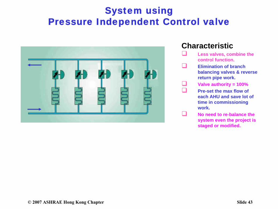
System using Pressure Independent Control valve
CharacteristicLess valves, combine the control function.Elimination of branch balancing valves & reverse return pipe work.Valve authority = 100%Pre-set the max flow of each AHU and save lot of time in commissioning work.No need to re-balance the system even the project is staged or modified.
© 2007 ASHRAE Hong Kong Chapter Slide 44
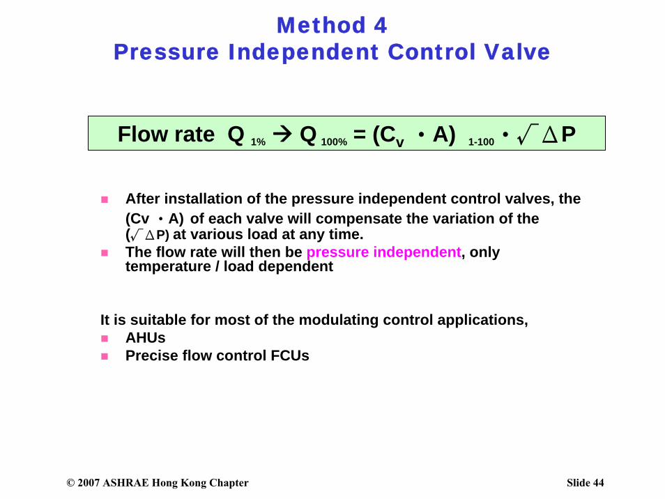
Method 4Pressure Independent Control Valve
After installation of the pressure independent control valves, the (Cv ‧A) of each valve will compensate the variation of the (√ΔP) at various load at any time.The flow rate will then be pressure independent, only temperature / load dependent
It is suitable for most of the modulating control applications,AHUsPrecise flow control FCUs
Flow rate Q 1% Q 100% = (Cv ‧A) 1-100‧√ΔP
© 2007 ASHRAE Hong Kong Chapter Slide 45
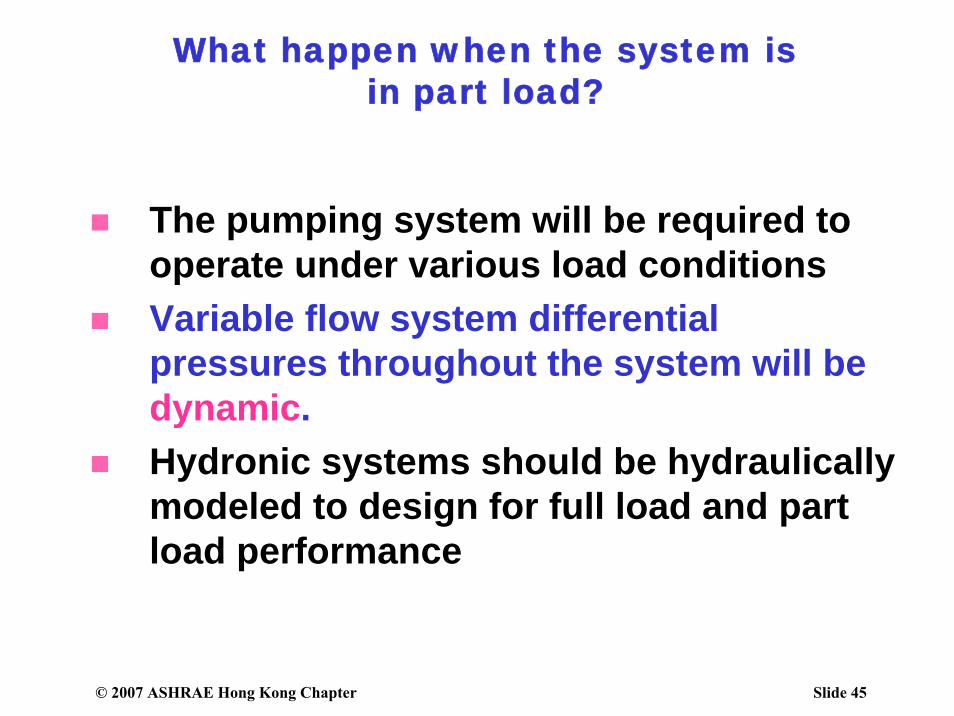
The pumping system will be required to operate under various load conditionsVariable flow system differential pressures throughout the system will be dynamic.Hydronic systems should be hydraulically modeled to design for full load and part load performance
What happen when the system is in part load?
© 2007 ASHRAE Hong Kong Chapter Slide 46
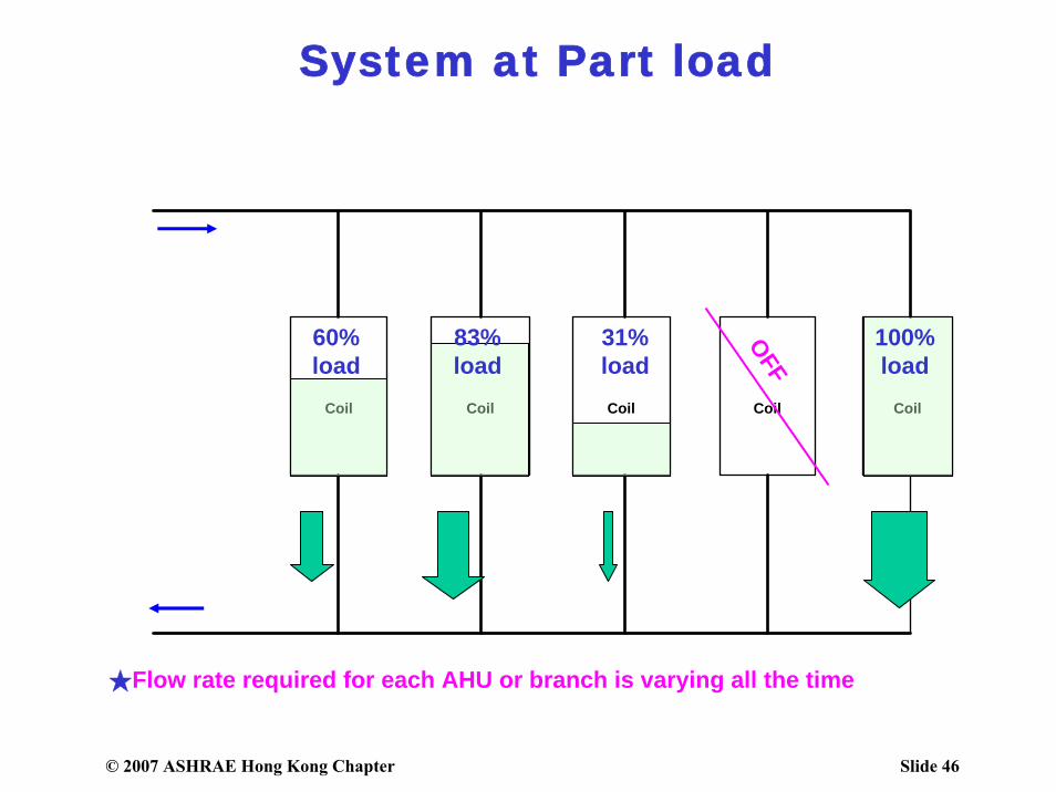
System at Part load
Coil Coil Coil Coil Coil
OFF
60%load
83%load
31%load
100%load
★Flow rate required for each AHU or branch is varying all the time
© 2007 ASHRAE Hong Kong Chapter Slide 47
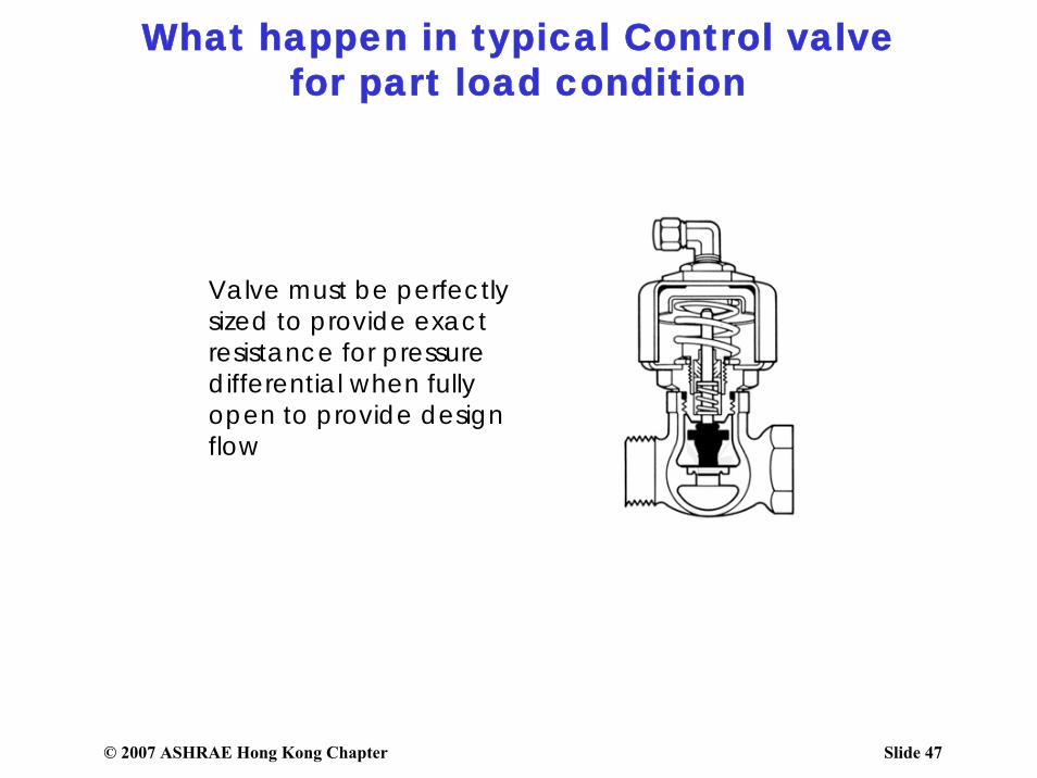
Valve must be perfectly sized to provide exact resistance for pressure differential when fully open to provide design flow
What happen in typical Control valve for part load condition
© 2007 ASHRAE Hong Kong Chapter Slide 48
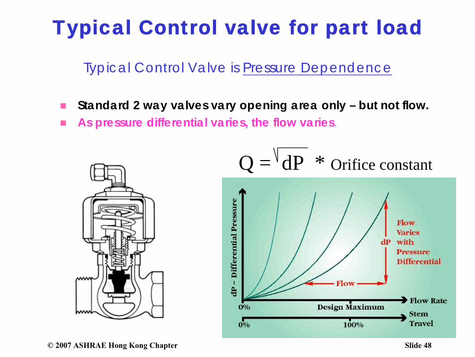
Typical Control Valve is Pressure Dependence
Standard 2 way valves vary opening area only – but not flow.As pressure differential varies, the flow varies.
Q = dP * Orifice constant
Typical Control valve for part load
© 2007 ASHRAE Hong Kong Chapter Slide 49
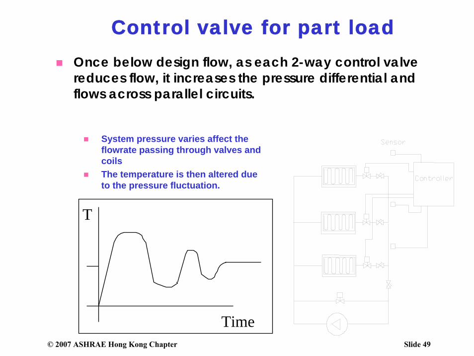
Once below design flow, as each 2-way control valve reduces flow, it increases the pressure differential and flows across parallel circuits.
T
Time
System pressure varies affect the flowrate passing through valves and coilsThe temperature is then altered due to the pressure fluctuation.
Control valve for part load
© 2007 ASHRAE Hong Kong Chapter Slide 50
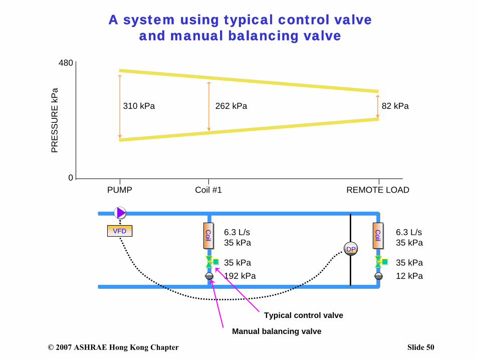
A system using typical control valve and manual balancing valve
VFD Coil
Coil
DP
6.3 L/s35 kPa
6.3 L/s35 kPa
35 kPa192 kPa
35 kPa12 kPa
82 kPa262 kPa310 kPa
PUMP Coil #1 REMOTE LOAD0
480PR
ESSU
RE
kPa
Typical control valve
Manual balancing valve
© 2007 ASHRAE Hong Kong Chapter Slide 51
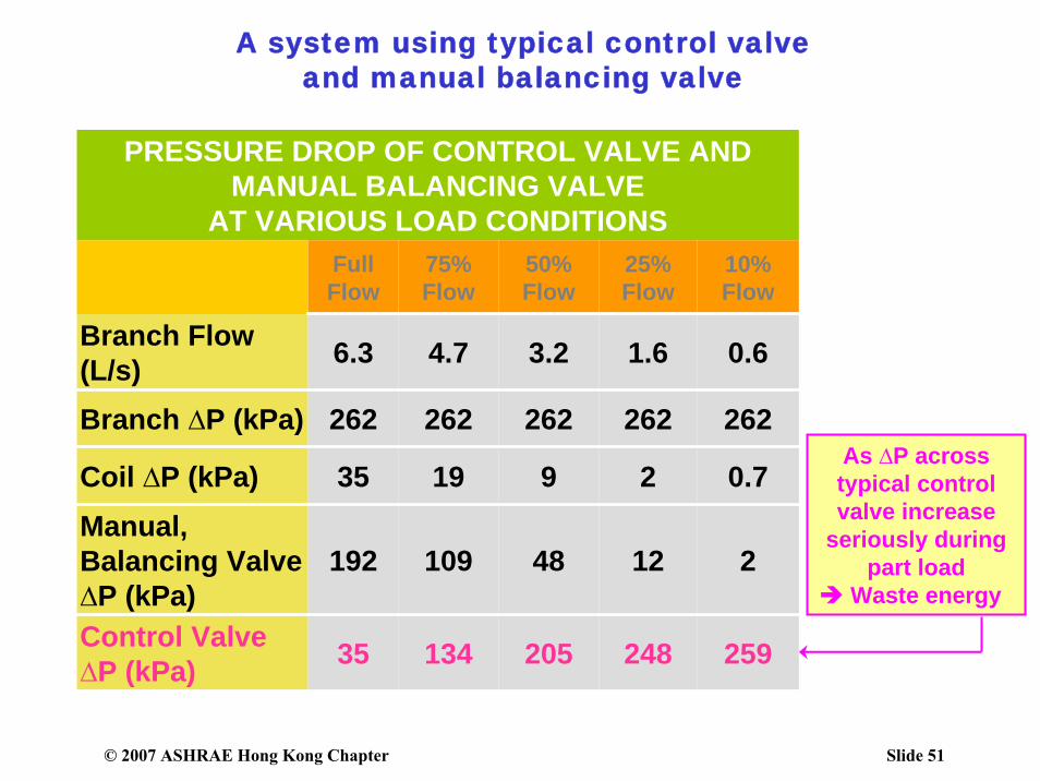
A system using typical control valve and manual balancing valve
PRESSURE DROP OF CONTROL VALVE AND MANUAL BALANCING VALVE
AT VARIOUS LOAD CONDITIONSFull Flow
75% Flow
50% Flow
25% Flow
10% Flow
Branch Flow (L/s) 6.3 4.7 3.2 1.6 0.6
Branch ∆P (kPa) 262 262 262 262 262
Coil ∆P (kPa) 35 19 9 2 0.7Manual, Balancing Valve ∆P (kPa)
192 109 48 12 2
Control Valve ∆P (kPa) 35 134 205 248 259
As ∆P across typical control valve increase
seriously during part load
Waste energy
© 2007 ASHRAE Hong Kong Chapter Slide 52
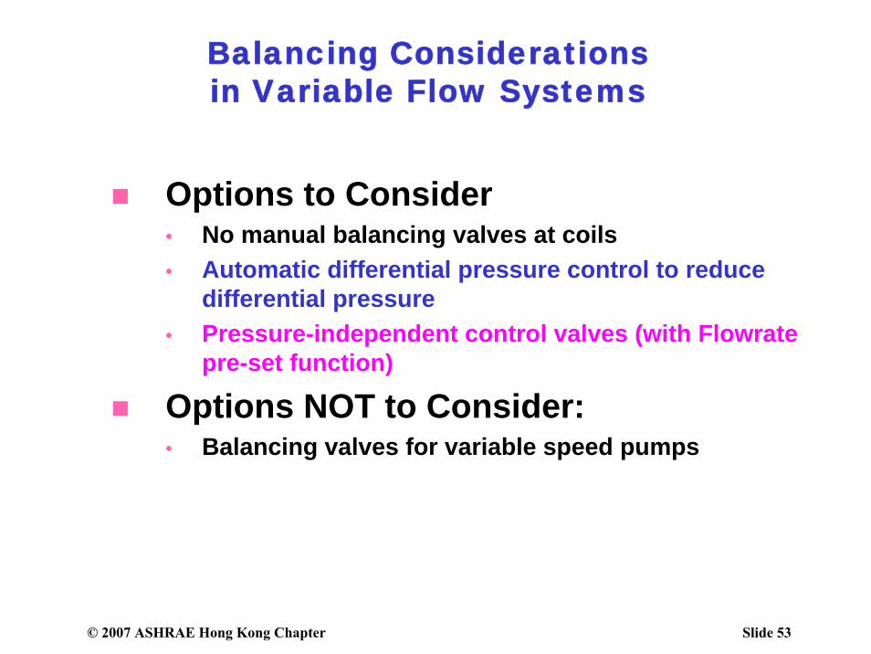
Balancing Considerationsin Variable Flow Systems
• Too large a balancing valve pressure drop will affect the performance and flow characteristic of the control valve.• ASHRAE 2003 Applications Handbook, page 37.8
© 2007 ASHRAE Hong Kong Chapter Slide 53
Options to Consider• No manual balancing valves at coils• Automatic differential pressure control to reduce
differential pressure• Pressure-independent control valves (with Flowrate
pre-set function)
Options NOT to Consider:• Balancing valves for variable speed pumps
Balancing Considerationsin Variable Flow Systems
© 2007 ASHRAE Hong Kong Chapter Slide 54
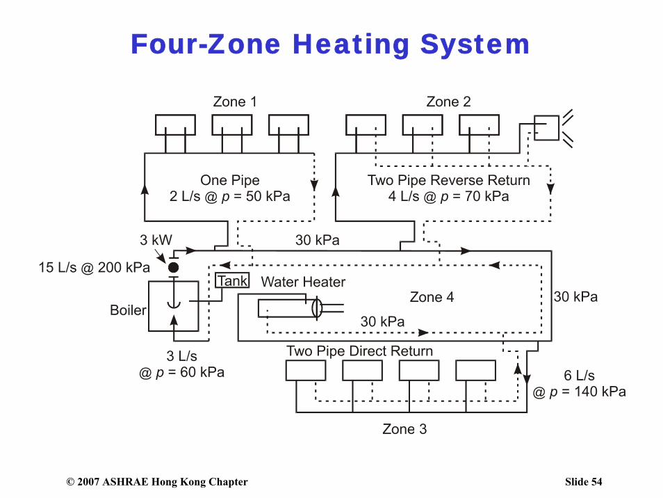
Four-Zone Heating System

© 2007 ASHRAE Hong Kong Chapter Slide 55
Typical Building Layout
Building usage•Hotel •Shopping Mall•Services apartment•Office•Mechanical floor
© 2007 ASHRAE Hong Kong Chapter Slide 56
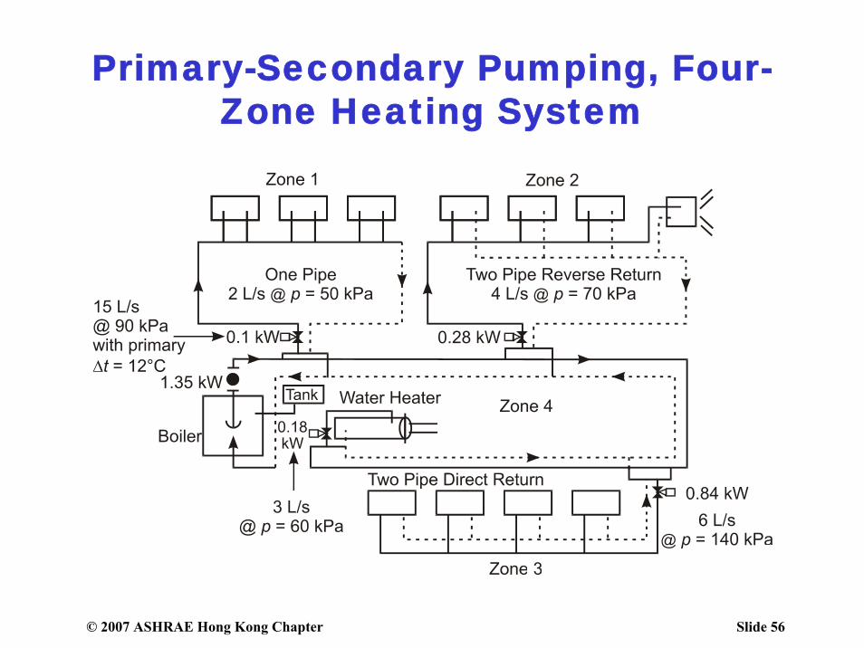
Primary-Secondary Pumping, Four-Zone Heating System

© 2007 ASHRAE Hong Kong Chapter Slide 57
Primary-Secondary Bridge Energy
© 2007 ASHRAE Hong Kong Chapter Slide 58
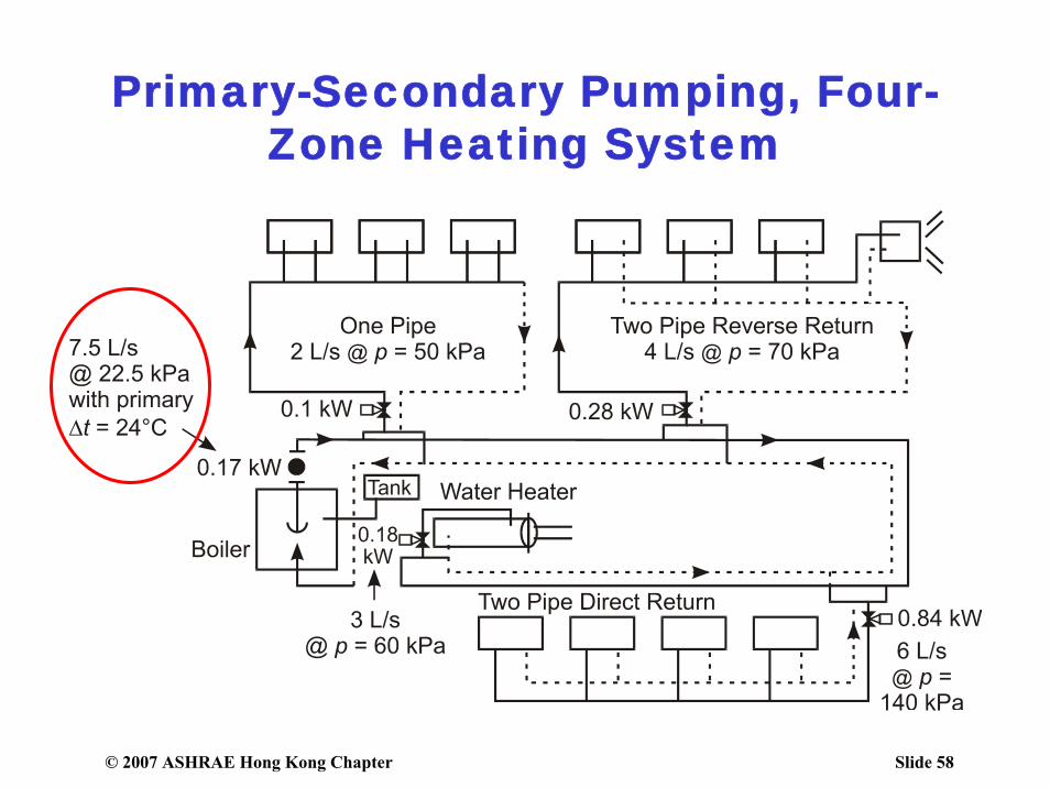
Primary-Secondary Pumping, Four-Zone Heating System
© 2007 ASHRAE Hong Kong Chapter Slide 59
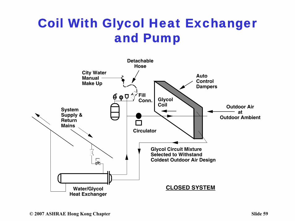
Coil With Glycol Heat Exchanger and Pump
© 2007 ASHRAE Hong Kong Chapter Slide 60
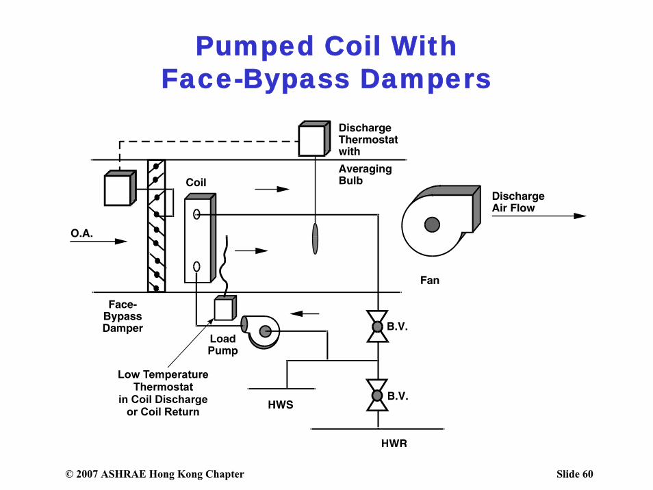
Pumped Coil WithFace-Bypass Dampers
© 2007 ASHRAE Hong Kong Chapter Slide 61
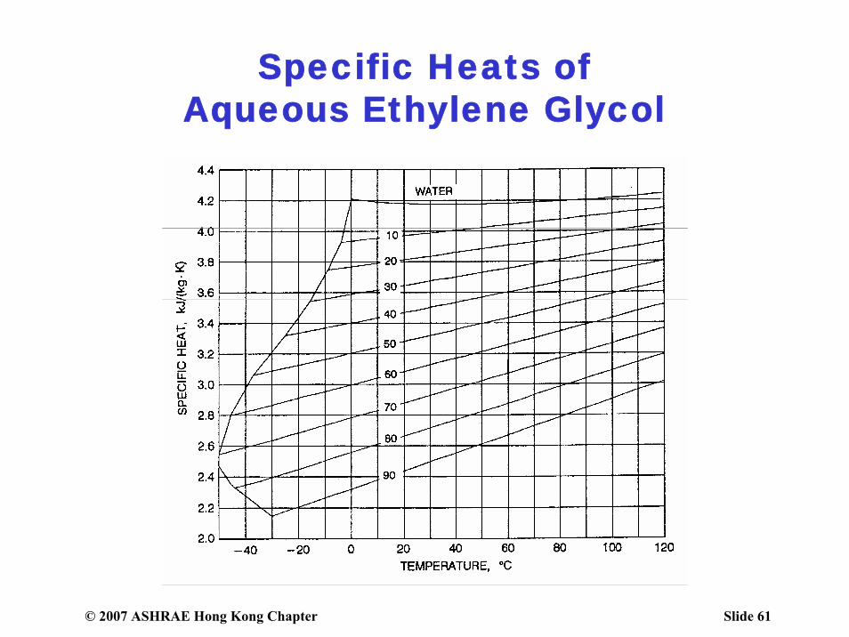
Specific Heats ofAqueous Ethylene Glycol

© 2007 ASHRAE Hong Kong Chapter Slide 62
Specific Heats ofAqueous Propylene Glycol
© 2007 ASHRAE Hong Kong Chapter Slide 63
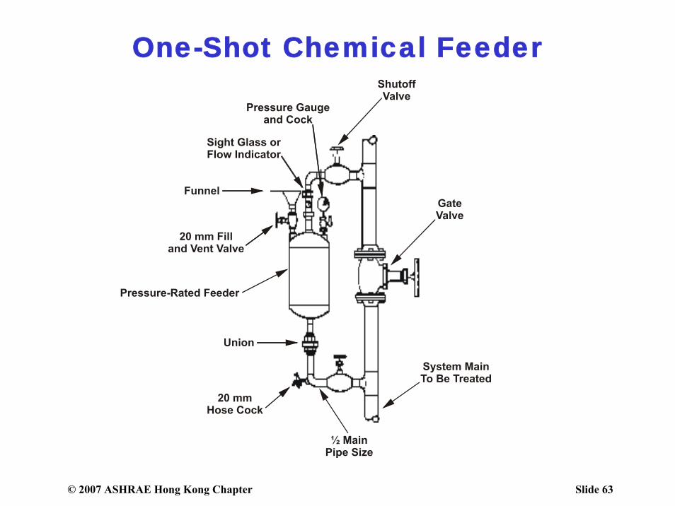
One-Shot Chemical Feeder


![Paper Title - ASHRAE Library/Conferences... · Paper Title Author Name, PhD, PE Author Name Author Name, PE [ASHRAE Affiliation] Student Member ASHRAE Fellow ASHRAE ABSTRACT HEADING](https://img.pdfslide.net/doc/110x75/5f71b39d1a193b0c14194175/paper-title-ashrae-libraryconferences-paper-title-author-name-phd-pe-author.jpg)