Embed Size (px)
DESCRIPTION
Metal cutting, Tool Engineering, Machining science
Citation preview

SCHOOL OF MECHANICAL
DEPARTMENT OF MECHANICAL ENGINEERING
LESSON NOTES
U4MEA15 MANUFACTURING TECHNOLOGY-II
VELTECH Dr.RR & Dr.SR TECHNICAL UNIVERSITY
U4MEA15 MANUFACTURING TECHNOLOGY – II L T P C
1
3 0 0 3OBJECTIVE:To Understand The Concept And Basic Mechanics Of Metal Cutting, Working Of Standard Machine Tools Such As Lathe, Shaping And Allied Machines, Milling, Drilling And Allied Machines, Grinding And Allied Machines And Broaching. To Understand The Basic Concepts Of (CNC) Computer Numerical Control Of Machine Tools And CNC Programming.
UNIT I: THEORY OF METAL CUTTING 9 Introduction: Material Removal Processes, Types Of Machine Tools – Theory Of Metal Cutting: Chip Formation, Orthogonal Cutting, Cutting Tool Materials, Tool Wear, Tool Life, Surface Finish, Cutting Fluids.
UNIT II: CENTRE LATHE AND SPECIAL PURPOSE LATHES 9 Centre Lathe, Constructional Features, Cutting Tool Geometry, Various Operations, Taper Turning Methods, Thread Cutting Methods, Special Attachments, Machining Time And Power Estimation. Capstan And Turret Lathes – Automats – Single Spindle, Swiss Type, Automatic Screw Type, Multi Spindle - Turret Indexing Mechanism, Bar Feed Mechanism.
UNIT III: MACHINE TOOLS 9 Shaper, Planer, Slotter, Milling- Types And Operations. Drilling – Types And Operations - Broaching Machines-Push, Pull Broaching Machines. Gear Cutting, Forming, Generation And Gear Finishing Process. Abrasive Processes: Grinding Wheel – Specifications And Selection, Types Of Grinding Process – Cylindrical Grinding, Surface Grinding, Centreless Grinding– Honing, Lapping, Super Finishing, Polishing And Buffing
UNIT IV: UNCONVENTIONAL MACHINING PROCESS 9 Unconventional Machining Process - Classification, Abrasive Jet Machining, Ultrasonic Machining, Electric Discharge Machining, Electron Beam Machining, Laser Beam Machining, Ion Beam Machining, Electro Chemical Machining.
UNIT V: CNC MACHINE TOOLS AND PART PROGRAMMING 9 Numerical Control (NC) Machine Tools – CNC: Types, Constructional Details, Special Features – Design Considerations Of CNC Machines For Improving Machining Accuracy – Structural Members – Slide Ways –Linear Bearings – Ball Screws – Spindle Drives And Feed Drives. Part Programming Fundamentals – Manual Programming – Computer Assisted Part Programming.
TOTAL : 45 Periods
2

TEXT BOOKS1. Sharma, P.C., A Textbook Of Production Technology - Vol I And II, S. Chand & Company
Ltd., New Delhi, 1996 2. Rao, P.N., Manufacturing Technology, Vol I & II, Tata Mcgraw Hill Publishing Co., New
Delhi, 1998
REFERENCE BOOKS1. HMT – “Production Technology”, Tata Mcgraw-Hill, 1998.
2. P.N.Rao, ‘CAD/CAM Principles And Applications’, TATA Mc Craw Hill, 20073. P.C. Sharma, “A Text Book Of Production Engineering”, S. Chand And Co. Ltd, IV Edition, 1993.4. Shrawat N.S. And Narang J.S, ‘CNC Machines’, Dhanpat Rai & Co., 2002.5. M.P.Groover And Zimers Jr., ‘CAD/CAM’ Prentice Hall Of India Ltd., 2004.6. Milton C.Shaw, ‘Metal Cutting Principles’, Oxford University Press, Second Edition, 2005.7. Philip F.Ostwald And Jairo Munoz, ‘Manufacturing Processes And Systems’, John Wiley And Sons, 9th Edition,2002.
UNIT – I
THEORY OF METAL CUTTING
PART – A
3

Process Of Metal Shaping.
Process Of Metal Shaping Is Classified Into Two Types Namely.i. Non-Cutting Shaping Processii. Cutting Shaping Process
Non-Cutting Shaping Process.
The Metal Is Shaped Under The Action Of Force, Heating Or Both. Since There Is No Cutting Of Metal, Chip Formation Will Not Be There. So, It Is Called Non-Cutting Shaping Process.
Cutting Shaping Process.
The Required Shape Of Metal Is Obtained By Removing The Unwanted Material From The Work Piece In The Form Of Chips Is Called Cutting Shaping Process. Example: Turning, Drilling, Milling, Boring Etc.
Relative Motion Between Work Piece And Cutting Tool.
i. Rotation Of Work Against The Tool. Example: Turningii. Rotation Of Tool Against Work Piece. Example: Drilling, Milling.iii. Linear Movement Of The Work Piece Against The Tool Example:
Planer.iv. Linear Movement Of The Tool Against The Work. Example –
Shaper
The Different Types Of Cutting Tool
a. Single Point Cutting Tool.b. Multiple Point Cutting Tool.
The Various Parts Single Point Cutting Tool.
1. Shank 2. Face 3. Flank4. Base 5. Nose 6. Cutting Edge
The Various Angles In Cutting Tool.
1. Back Rake Angle 2. Side Rake Angle3. End Relief Angle 4. Side Relief Angle5. Side Cutting Angle 6. End Cutting Angle.
4

Tool Signature
The Various Angles Of Tools Are Mentioned In A Numerical Number In Particular Order. That Order Is Known As Tool Signature.
The Effect Of Back Rake Angle And Mention The Types
Back Rake Angle Of Tool Increases The Strength Of Cutting Tool And Cutting Action.
It Is Classified Into Two Types:1. Positive Rake Angle2. Negative Rake Angle
Side Rake Angle And Mention Its Effects
The Angle Between The Tool Face And The Line Parallel To The Base Of The Tool Is Known As Side Rake Angle. It Is Used To Control Chip Flow.
Clearance Angle And Mention The Types
These Are The Slopes Ground Downwards From The Cutting Edges. The Clearance Angle Can Be Classified Into Two Types.
i. Side Relief Angle.ii. End Relief Angle.
The Nose Radius.
It Is The Joining Of Side And End Cutting Edges By Means Of Small Radius In Order To Increase The Tool Life And Better Surface Finish On The Work Piece.
All Conditions For Using Positive Rake Angle
a. To Machine The Work Hardened Materials.b. To Machine Low Strength Ferrous And Non-Ferrous Metals.c. To Turn The Long Shaft Of Small Diameters.d. To Machine The Metal Below Recommended Cutting Speeds.e. To Machine The Workpiece Using Small Machine Tools With Low
Horsepower.
The Negative Rake Angles a. To Machine High Strength Alloys.
5

b. The Machine Tools Are More Rigid.c. The Feed Rates Are High.d. To Give Heavy And Interrupted Cuts.
Types Of Metal Cutting Process.
The Metal Cutting Processes Are Mainly Classified Into Two Types.a. Orthogonal Cutting Process(Two Dimensional Cutting)b. Oblique Cutting Process (Three Dimensional Cutting)
Orthogonal And Oblique Cutting.
Orthogonal Cutting: The Cutting Edge Of Tool Is Perpendicular To The Workpiece Axis.
Oblique Cutting: The Cutting Edge Is Inclined At An Acute Angle With Normal To The Cutting Velocity Vector Is Called Oblique Cutting Process.
Shear Plane
The Material Of Work Piece Is Stressed Beyond Its Yield Point Under The Compressive Force. This Causes The Material To Deform Plastically And Shear Off. The Plastic Flow Takes Place In A Localized Region Called Shear Plane.
Cutting Force
The Sheared Material Begins To Flow Along The Cutting Tool Face In The Form Of Small Pieces. The Compressive Force Applied To Form The Chip Is Called Cutting Force.
Chip And Its Different Types
The Sheared Material Begins To Flow Along The Cutting Tool Face In The Form Of Small Pieces Is Called Chip. Chips Are Mainly Classified Into Three Types:
a. Continuous Chipb. Discontinuous Chipc. Continuous Chip With Built Up Edge.
6

Continuous Chip Formed
The Following Factors Favour The Formation Of Continuous Chip.I. Ductile Material Ii. Smaller Depth Of CutIii. High Cutting Speed Iv. Large Rake AngleV. Sharp Cutting Edge Vi. Proper Cutting FluidVii. Low Friction Between Tool Face And Chips.
The Favourable Factors For Discontinuous Chip Formation
a. Machining Of Brittle Materialb. Small Rake Anglec. Higher Depth Of Cutd. Low Cutting Speedse. Excess Cutting Fluidf. Cutting Ductile Material With Low Speed And Small Rake Angle Of
The Tool
The Favourable Factors For Continuous Chip With Built Up Edge
a. Low Cutting Speedb. Small Rake Anglec. Coarse Feedd. Strong Adhesion Between Chip And Tool Face.e. Insufficient Cutting Fluidf. Large Uncut Thickness
Chip Thickness Ratio
The Ratio Of Chip Thickness Before Cutting To Chip Thickness After Cutting Is Called Chip Thickness Ratio.
Chip Reduction Co-Efficient
The Reciprocal Of Chip Thickness Ratio Is Called Chip Reduction Co-Efficient.
The Purposes Of Chip Breakers
7

The Chip Breakers Are Used To Break The Chips Into Small Pieces For Removal, Safety And To Prevent Both The Machine And Work Damage.
The Difficulties Involved Due To Long And Continuous Chip
During Machining, Long And Continuous Chip That Are Formed At High Cutting Speed Will Affect Machining. It Will Spoil Tool, Work And Machine. These Chips Are Hard, Sharp And Hot. It Will Be Difficult To Remove Metal And Also Dangerous To Safety.
The Different Types Of Chip Breakers.
The Chip Breakers Are Classified Into Three Types.
a. Step Typeb. Groove Typec. Clamp Type
Cutting Forces Acting On The Cutting Tool
During The Cutting Process, The Following Three Components Of Cutting Forces Are Acting Mutually Right Angles.
a. Feed Force Fx Acts In A Horizontal Plane But In The Direction Op-posite To Feed.
b. Thrust Force Fy Acts In A Direction Perpendicular To The Gener-ated Surface.
c. Cutting Force Fz Acts In The Direction Of The Main Cutting Motion.
The Assumption Made In Merchant Circle
a. The Chip Formation Will Be Continuous Without Built Up Edge.b. During Cutting Process, Cutting Velocity Remains Constant.c. The Cutting Tool Has A Sharp Cutting Edge So That It Does Not
Make Flank Contact To The Work Piece.
Metal Removal Rate
8

It Is Defined As The Volume Of Metal Removed In Unit Time. It Is Used To Calculate Time Required To Remove Specified Quantity Of Material From The Work Piece.
The Assumptions Made In Lee And Shaffer’s Theory
a. The Work Ahead Of The Tool Behaves As Ideal Plastic Mass.b. There Exists A Shear Plane Which Separates The Chip And Work
Piece.c. No Hardening In Chip Occurs.
The Tool Energy Of The Cutting Process.
Total Energy Per Unit Volume Is Approximate Equal To The Sum Of Following Four Energies.
a. Shear Energy Per Unit Volume In Shear Plane.b. Friction Energy Per Unit Volume In Tool Face.c. Surface Energy Per Unit Volume Due To The Formation Of A New
Surface Area Is Cutting.d. Momentum Energy Per Unit Volume Due To The Change In Mo-
mentum Associated With The Metal As It Crosses The Shear Plane.
Machinability Of Metal. Machinability Is Defined As The Ease With Which A Material Can
Be Satisfactorily Machined.
The Factors Affecting The Machinability
a. Chemical Composition Of Work Piece Material.b. Microstructure Of Work Piece Materialc. Mechanical Properties Like Ductility, Toughness Etc.d. Physical Properties Of Work Materials.e. Method Of Production Of The Work Materials.
The Tool Variables Affecting The Machinability
a. Tool Geometry And Tool Materialb. Nature Of Engagement Of Toll With The Workc. Rigidity Of Tool
The Machine Variables Affecting The Machinability
9
a. Rigidity Of Machineb. Power And Accuracy Of The Machine Tool
Machinability Evaluated
The Following Criteria Are Suggested For Evaluating Machinability:
a. Tool Life Per Grindb. Rate Of Removal Per Tool Grindc. Magnitude Of Cutting Forces And Power Consumptiond. Surface Finishe. Dimensional Stability Of Finished Workf. Heat Generated During Cuttingg. Ease Of Chip Disposalh. Chip Hardness, Shape And Size
Advantage Of High Machinability.
a. Good Surface Finish Can Be Produced.b. High Cutting Speed Can Be Usedc. Less Power Consumptiond. Metal Removal Rate Is Highe. Less Tool Wear.
Machinability Index
It Is A Composition Of Machinability Of Different Material To Standard Materials. US Material Standard For 100% Machinability Is SAE 1112 Hot Rolled Steel.
The Tool Wear.
The Tool Wear Is Generally Classified As Follows.
i. Flank Wear Or Crater WearIi. Face Weariii. Nose Wear
Tool Life Is Defined
Tool Life Is Defined As The Time Elapsed Between Two Consecutive Tool Resharpening. During This Period The Tool Serves Effectively And Efficiently.
10

Taylor’s Tool Life Equation.Taylor’s Tool Life EquationVtn = CWhere. V = Cutting Speed In M/Min
T = Tool Life In MinuteC = ConstantN = Index Depends Upon Tool And Work
The Ways Of Representing Tool Life
The Following Are Some Of The Ways Of Expressing Tool Life.1. Volume Of Metal Removed O Expressing Tool Life.2. Number Of Work Piece Machined Per Grind3. Time Unit
The Factors Affecting Tool Life
I. Cutting SpeedIi. Feed And Depth Of CutIii. Tool GeometryIv. Tool MaterialV. Cutting FluidVi. Work MaterialVii. Rigidity Of Work, Tool And Machine
The Factors Considered For The Selection Of Cutting Speed
1. Tool Life2. Properties Of Material Being Machined3. Rate Of Feed4. Depth Of Cut5. Tool Geometry6. Cutting Fluid Used7. Type Of Machining Process8. Surface Finish To Be Obtained
The Factors To Be Considered For The Selection Of Tool Materials
i. Volume Of Productionii. Tool Designiii. Type Of Machining Processiv. Physical And Chemical Propertiesv. Rigidity And Condition Of Machine
11

The Important Properties Of Cutting Tool Materials
i. Hot Hardnessii. Wear Resistanceiii. High Thermal Conductivityiv. Resistance To Thermal Shockv. Easy To Grind And Sharpenvi. Low Mechanical And Chemical Affinity For The Work Material.
Four Tools Material.
i. Carbon Tool Steelii. High Speed Steeliii. Cemented Carbidesiv. Ceramicsv. Diamonds
The Function Of Cutting Fluids
i. It Is Used To Cool The Cutting Tool And Work Pieceii. It Lubricates The Cutting Tool And Thus Reduces The Co-Efficient Of
Friction Between Tool And Work.iii. It Improves The Surface Finish As Stated Earlier.iv. It Causes The Chips To Break Up Into Small Parts.v. It Protects The Finished Surface From Corrosionvi. It Washes Away The Chips From The Tool. It Prevents The Tool
From Fouling.vii. It Prevents Corrosion Of Work And Machine.
The Properties Of Cutting Fluid
i. It Should Have Good Lubricant Propertiesii. High Heat Absorbing Capacityiii. It Should Have A High Specific Heat, High Heat Conductivity And
High Film Co-Efficient.iv. High Flash Pointv. It Should Be Odorlessvi. It Should Be Non-Corrosive To Work And Tool.vii. It Should Have Low Viscosity To Permit Free Flow Of The Liquid.
Built Up Edge
During Cutting Process, The Interface Temperature And Pressure Are Quite High And Also High Friction Between Tool Chip Interface
12
Causes The Chip Material To Weld Itself To The Tool Face Near The Nose. This Is Called Built Up Edge.
The Various Cutting Fluids.
The Cutting Fluids Are Mainly Classified Into Two Types NamelyI. Water Based Cutting FluidsIi. Straight Or Heat Oil Based Cutting Fluids.
Differentiate Between Orthogonal Cutting And Oblique Cutting.
S. No Orthogonal Cutting Oblique Cutting
1The Cutting Edge Of The Tool Is Perpendicular To The Cutting Velocity Vector
The Cutting Edge Is Inclined At An Acute Angle With The Normal To The Cutting Velocity Vector
2
The Chip Flows Over The Tool Face And The Direction Of Chip-Flow Velocity Is Normal To The Cutting Edge
The Chip Flows On The Tool Face Making An Angle With The Normal On The Cutting Edge
3The Cutting Edge Clears The Width Of The Work Piece On Either Ends (I.E.No Side Flows
The Cutting Edge May Or May Not Clear The Width Of The Work Piece.
4The Maximum Chip Thickness Occurs At Its Middle
The Maximum Chip Thickness May Not Occur At The Middle
Relief/Clearance Angles Never Be Zero Or Negative
It Relief/ Clearance Angles Are Zero Or Negative The Tool Will Rub Against The Job. So, Tool Will Get Overhead And Cutting Is Not Proper. So, You Will Get A Poor Surface Finish.
Negative Rake Angle
The Slope Given Away From The Cutting Edge Is Called Negative Rake Angle.
The Diamond Tools Be Used
Diamond Is The Hardest Material. It Is Used For Machining Very Hard Materials Such As Glass, Plastics, Ceramics Etc.
The Advantages Of Increasing Nose Radius
If The Nose Radius Increases The Strength Of Cutting Tool Is Increased And It Is Used On Castings And Cast Iron, Where The Cuts Are Interrupted.
13

The Equations Of Velocity Of Chip And Velocity Of Shear In Terms Of Cutting Velocity, Rake Angle And Shear Angle.
The Shear Angle In Terms Of Chip Thickness And Rake Angle Of The Tool.
The Composition Of High-Speed Steel
High-Speed Steel Contains Tungsten – 18% And Vanadium – 1%. It Has About 0.75% Carbon.
The Causes Of Wear
The Tool Is Subjected To Three Important Factors Such As Force, Temperature And Sliding Action Due To Relative Motion Between Tool And The Work Piece. So, The Tool Is Wear Easily.
14

PROBLEMS:
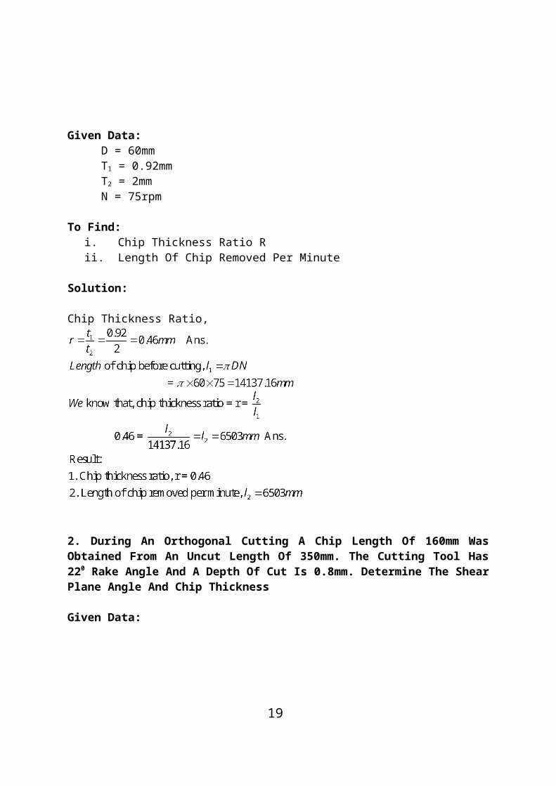
1. A Mild Steel Work Piece Of 60mm Diameter Is To Be Turned With An Orthogonal Tool To A Feed Rate Of 0.92 Mm/Revolution And At 75 Rpm. If The Chip Thickness Is 2mm, Determine The Chip Thickness Ratio And Length Of Chip Removed In One Minute. Assume A Condition Of Continuous Chip.
Given Data:D = 60mmT1 = 0.92mmT2 = 2mmN = 75rpm
To Find:i. Chip Thickness Ratio Rii. Length Of Chip Removed Per Minute
Solution:
Chip Thickness Ratio,
15

2. During An Orthogonal Cutting A Chip Length Of 160mm Was Obtained From An Uncut Length Of 350mm. The Cutting Tool Has 220 Rake Angle And A Depth Of Cut Is 0.8mm. Determine The Shear Plane Angle And Chip Thickness
Given Data:
Solution:
16

3. In Orthogonal Cutting Process The Following Observations Were MadeDepth Of Cut = 0.25mmChip Thickness Ratio = 0.45Width Of Cut = 4mmCutting Velocity = 40m/Min
Cutting Force Component Parallel To Cutting Velocity Vector = 1150NCutting Force Component Normal To Cutting Velocity Vector = 140NRake Angle = 180
Determine Resultant Cutting Force, Power Of Cutting, Shear Plane Angle, Friction Angle And Force Component Parallel To Shear Plane
Given Data:
17

Solution:
Result:
4. A Seamless Tube 32mm Outside Diameter Is Turned On A Lathe. Cutting Velocity Of The Tool Relative To The Work Piece Is 10m/Min. Rake Angle = 350, Depth Of Cut = 0.125m, Length Of Chip = 60mm, Horizontal Cutting Force Of The Tool On The Work Piece = 200N. Cutting Force Required To Hold The Tool Against The Work Piece = 80N. Calculate
i. Co-Efficient Of Frictionii. Chip Thickness Ratioiii. Shear Plane Angleiv. Velocity Relative To The Tool, Andv. Velocity Of Chip Relative To The Work Piece
Given Data:
18
D = 32mmV = 10m/Min = 350
T1 = 0.125mmL2 = 60mmFz = 200NFx = 80NTo Find:, , R, Vc, And Vs
Solution:
Result:
19

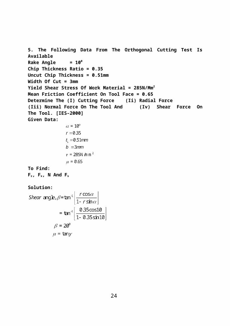
5. The Following Data From The Orthogonal Cutting Test Is Available Rake Angle = 100
Chip Thickness Ratio = 0.35Uncut Chip Thickness = 0.51mmWidth Of Cut = 3mmYield Shear Stress Of Work Material = 285N/Mm2
Mean Friction Coefficient On Tool Face = 0.65Determine The (I) Cutting Force (Ii) Radial Force(Iii) Normal Force On The Tool And (Iv) Shear Force On The Tool. [IES–2000]Given Data:
To Find:Fz, Fx, N And Fs
Solution:
20

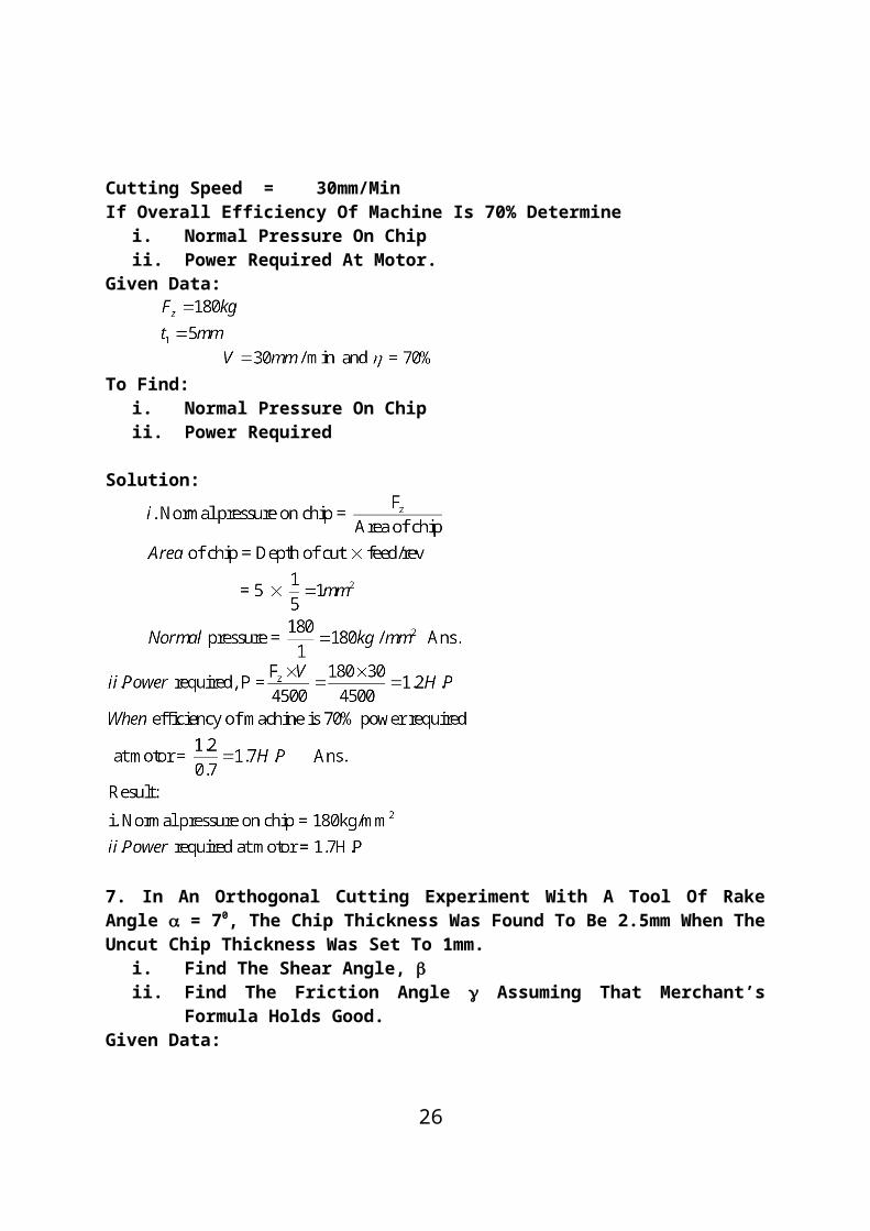
6. The Following Observations Are Made From A Metal Cutting Test Cutting Force = 180kgFeed = 5 Cuts/MinDepth Of Cut = 5mmCutting Speed = 30mm/MinIf Overall Efficiency Of Machine Is 70% Determine
21

i. Normal Pressure On Chipii. Power Required At Motor.
Given Data:
To Find:
i. Normal Pressure On Chipii. Power Required
Solution:
7. In An Orthogonal Cutting Experiment With A Tool Of Rake Angle = 70, The Chip Thickness Was Found To Be 2.5mm When The Uncut Chip Thickness Was Set To 1mm.
i. Find The Shear Angle, ii. Find The Friction Angle Assuming That Merchant’s For-
mula Holds Good.Given Data:
22

Solution:
8. If The Relationship For H.S.S Tools Is VT1/8 = C1 And For Tungsten Carbide Tools Is VT1/5 = C2 And Assuming That At A Speed Of 25m/Min, The Tool Life Was 3 Hours In Each Case, Compare Their Cutting Lives At 32m/Min.Given Data:
To Find:Compare Cutting Lives At 32m/Min
23
Solution:
9. In A Tool Wear Test With High-Speed Steel Cutting Tool, The Following Data Were Recorded.
Tool Life
Cutting Speed
30min2min
25m/Min70m/Min
Compute The Taylor’s Equation [M.U. Oct ‘97]Given Data:
T1 = 30minV1 = 25m/MinT2 = 2minV2 = 70m/Min
To Find:Compute The Taylor’s Equation.
Solution:Taylor’s Equation Is Vtn = C
24

10. The Following Data From An Orthogonal Cutting Test Is Available Rank Angle = 150
Chip Thickness Ratio = 0.383Uncut Chip Thickness = 0.5mmWidth Of Cut, B = 3mmYield Stress Of Material In Shear = 280 N/Mm2
Average Coefficient Of Friction On The Tool Face = 0.7Determine The Normal And Tangential Forces On The Tool Face.
[M.U.Oct 95]Given Data:
To Find:Normal Force And Tangential Force
Solution:
25
UNIT – II
26

CENTRE LATHE AND SPECIAL PURPOSE LATHES
PART – A
Lathe
Lathe Is A Machine Which Removes The Metal From A Piece Of Work To The Required And Size.
Hold A Workpiece In A Centre Lathe
Between The Two Centers Of Head Stock And Tail Stock
Swing Diameter
The Largest Diameter Of Work That Will Revolve Without Touching The Bed And Is Twice The High Of The Center Measured From The Bed Of The Lathe.
The Specification Of Typical Lathe1. The Length Of Bed2. Maximum Distance Between Dead And Live Centers.3. Type Of Bed I.E. Straight, Semi Gap Or Gap Type.4. The Height Of Centers From The Bed5. Swing Over The Bed6. Swing Over The Cross-Bed7. Width Of The Bed8. Spindle Bore9. Spindle Speed10. H.P. Of Main Motor And Rpm11. Number Of Spindle Speeds12. Spindle Nose Diameter13. Feeds 14. Floor Space Required.
The Tool Moves Perpendicular To The Axis Of The Work To Pro-duce_____________
Flat Surface
The Various Operations Can Be Performed On A Lathe
1. Turning
27

2. Facing3. Forming4. Knurling5. Chamfering6. Thread Cutting7. Drilling8. Boring9. Recessing10. Tapping11. Grooving Etc.
The Principle Parts Of A Lathe
1. Red 2. Headstock3. Tailstock 4. Carriage5. Cross-Slide 6. Tool Post
The Main Requisites Of A Lathe Bed
1. Red 2. Headstock 3. Tailstock4. Carriage 5. Cross-Slide 6. Too, Post
The Main Requisites Of A Lathe Bed
The Lathe Bed Should Be Very Strong To Withstand Cutting Forces And Vibrations During Machining.Provisions Are Made To Accommodate Other Parts Of A Lathe On The Bed
Guide Ways
The Uses Of Headstock
1. Headstock Carries A Hollow Spindle With Nose To Hold The Work Piece.2. To Mount The Driving And Speed Changing Mechanisms.
The Types Of Headstock
1. Back Geared Type 2. All Geared Type
28

The Name Of The Center Mounted On The Tailstock.
Dead Center
The Main Difference Between Live Center And Dead Center
I. Live Center Drives And Rotates Along With The Work Pieces.Ii. Dead Center Just Supports The Other End Of The Work Piece.
The Names Of Any Four Lathe Accessories.
Lathe Centres, Catch Plates, Carries, Chucks, Mandrels And Rests.
The Taper Is Formed On The Work Piece By Using Tailstock
The Upper Body Of Tailstock Can Be Moved Towards Or Away From The Operator.
The Position Of A Carriage.
The Carriage Is Mounted In Between Headstock And Tailstock.
The Various Parts Mounted On The Carriage.
a. Saddleb. Compound Restc. Cross Slided. Tool Post
The Shape And Position Of Saddle.
H Shaped Component Is Fitted Across The Lathe Bed.
Holes Drilled In A Center Lathe
First, The Dead Center Of The Tailstock Is Replaced By A Drill Bit. The Longitudinal Movement Of The Tailstock Is Locked After Setting The Approach Of Drill. Finally, The Hand Wheel Of The Tailstock Is Rotated For Making The Hole On The Specimen.
Compound Rest
A Member Or Part Which Is Mounted On The Top Of The Cross Slide
29

Having A Base Graduated In Degrees.
For Making Taper Portion Of Bigger Diameter At The Left End On The Given Work Piece. How The Tool Post Is Tilted
For Making Taper Portion Of Bigger Diameter At The Left End, The Tool Post End Should Be Set Towards The Bigger Diameter.
The Four Types Of Tool Post
1. Single Screw Tool Post 2. Open Side Tool Post3. Four Bolt Tool Post, And 4. Four Way Tool Post
The Cutting Tool Is Fixed On A Single Screw Tool Post And How Can Vary Tool Height
A Single Screw Tool Is Used To Hold Only Single Tool, Which Are Clamped By Clamping Screw. The Tool Height Can Be Varied By Adjusting A Rocker Placed On The Tool Post.
The Provision For Adjusting The Tool Height In Open-Side Tool Post.
Parallel Strips Packing Is Used To Adjust The Tool Height.
The Use Of Four-Bolt Tool Post
Two Tools May Be Held In Position By Two Straps And Four Bolts.
Type Tool Post Maximum Number Of Tools Can Be Mounted How Many
In Four Way Tool Post, Maximum Four Tools Can Be Mounted.
Apron
Apron Is An Integral Part Of Several Gears, Levers And Clutches Which Are Mounted With The Saddle For Moving The Carriage Along With Lead Screw While Thread Cutting.
Type Of Mechanism Is Used For Giving Automatic Feed To The Tool While Thread Cutting
30

Half Or Split Nut Mechanism.
Four Types Of Lathes
1. Engine Lathe 2. Bench Lathe 3. Tool Room Lathe4. Semi-Automatic Lathe 5. Automatic Lathe.
Bench Lathe
A Small Size Lathe Which Has All Parts Similar To A Center Lathe Which Can Be Mounted On A Bench.
Tool Room Lathe.
A Tool Room Lathe Consists Of All The Necessary Attachments Required For Accurate And Precision Machining.
Semi-Automatic Lathe
A Lathe In Which All The Machining Operations Are Performed Automatically But Loading And Unloading Of Work Piece, Coolant On Or Off Are Performed Manually.
Two Types Of Semiautomatic Lathe
1. Capstan Lathe 2. Turret Lathe
The Semi-Automatic Lathe Differs From Center Lathe
A Hexagonal Turret Head Replaces Tailstock.
The Advantages Semi-Automatic Lathes
1. Production Time Is Minimized2. Accuracy Will Be High3. Production Rate Is Increased
Automatic Lathe
In Addition To Automatic Machining Operations Loading And
31

Unloading Are Also Performed Automatically.
Special Purpose Lathe.
The Lathes Which Are Specially Designed For Carrying Out Specific Operations Only.
Copying Lathe
The Tool Of This Lathe Follows A Template Or Master Through A Stylus Or Tracer.
The Various Types Of Headstock
1. Back Geared 2. All Geared.
Feed.
Feed Is Defined As The Movement Of The Tool Relative To The Work And The Work Piece By Form Tool.
Various Feed Mechanism Used For Obtaining Automatic Feed.
1. Tumbler Gear Mechanism2. Quick Change Gearbox.3. Tumbler Gear-Quick Change Gearbox4. Apron Mechanism
Four Work Holding Devices.
1. Chucks2. Centres3. Face Plate4. Angle Plate.
The Use Of Chucks.
Chucks Are Use To Hold The Work Piece Of Small Length And Large Diameter.
The Various Types Of Chucks
32

5. Three Jaw Chuck (Or) Self Centering Chuck.6. Four Jaw Chuck Or Independent Chuck7. Magnetic Chuck
The Application Of Air Operated Chuck
Heavy Work Pieces Are Mounted With The Help Of Air-Operated Chucks. Because They Will Require More Power To Hold The Work Piece.
The Use Of Mandrels
Mandrels Are Used For Holding Hollow Work Pieces.
Steady And Follower Rest.
Steady Rest: It Is Fixed On Bed Way’s Of The Lathe By Clamping The Bolts.
Followers Rest: It Is Mounted On The Saddle And Moves Together With The Tool.
The Different Operations Performed On A Lathe
1. Centering 2. Straight Turning3. Rough Turning 4. Finish Turning5. Shoulder Turning 6. Facing7. Chamfering 8. Knurling Etc.
Filing Operation.
Filling Is The Process Of Removing Bars, Sharp Corners And Feed Marks On A Work Piece By Removing Very Small Amount Of Metal.
Forming Operation
Forming Is The Process Of Producing Concave, Convex And Any Irregular Shape.
The Process “Grooving”.
Grooving Is The Process Of Reducing The Diameter Of The Work Piece Over A Very Narrow Surface.
33

Parting Off Is An Operation Of _________.
Cutting A Work Piece After Machining
“Eccentric”
The Axis Of One Cylinder Is Off-Set With The Axis Of Other Cylinder.
Drilling Operation
Drilling Is The Operation Of Producing Cylindrical Hole In A Work Piece.
Reaming And Boring Operation
Reaming: It Is The Operation Of Finishing And Sizing Of Already Drilled Hole.
Boring: It Is The Process Of Enlarging A Already Drilled Hole.
Milling Operation
The Operation Of Removing Metal By Using Rotating Cutter Having Multiple Cutting Edges Is Known As Milling.
Tapping
Tapping Is The Operation Of Forming Internal Thread Of Small Diameter By Using A Multipoint Tool.
“Taper”.
Taper Is Defined As A Uniform Change In The Diameter Of A Work Piece Measured Along Its Length.
“Conicity”.
The Ratio Of The Difference In Diameters Of The Taper To Its Length.
34

Various Methods For Taper Turning Operation.
a. Form Tool Methodb. Tailstock Set Over Methodc. Compound Rest Methodd. Taper Turning Attachment Method
Formula For Calculating Tailstock Set Over Distance.
Formula For Calculating Taper Turning Angle By Compound Rest Method.
Determine The Angle At Which The Compound Rest Will Be Swiveled When Cutting A Taper On A Piece Of Work Having The Following Dimensions.
e. Outside Diameter – 60mmf. Length Of The Tapered Portion 80mm Andg. Smallest Diameter = 20mm
Given Data: D = 60mm
L = 80mm (Length Of Tapered Portion)D = 20mm
Solution:
35
C
20
A
80
B

Thread Cutting Operation
Thread Cutting Is The Operation Of Producing Continues Helical Groove On A Cylindrical Work Piece.
The Number Of Teeth On Various Change Gears Be Calculated
“Thread Catching”.
The Process Of Following The Same Path Of The Tool When It Has Traveled In The Previous Cut Is Called As Thread Catching Or Thread Picking-Up.
Taper Of A Given Work Piece Having ¼ Conicity.
61. Write Down The Formula To Find The Following Parameters.
36

The Important Requires Of Capstan And Turret Lathe.
1. Bed 2. Head Stock 3. Turret Head4. Saddle And Cross Slide
The Various Types Of Cross-Slide
1. Reach Over Type 2. Side Hung Type.
The Various Types Of Headstock For Turret Lathes
1. Back Geared 2. All Geared 3. Pre-Selective Stock
The Special Provision Made In Pre-Selective Headstock
The Speed Changing For Different Machining Operation Can Be Done By Simply Pushing A Button Or Pulling A Lever To Select The Speed Of The Next Operation In Advance.
Type Of Mechanism Is Used For Indexing The Turret Head For The Next Operation
Geneva Or Indexing Mechanism
Two Specification Of Capstan And Turret Lathe.
1. Number Of Spindle Speeds
37

2. Number Of Feeds For The Turret Of Saddle
The Advantages Of Turret Lathe Over Capstan Lathe.
1. Heavier And Larger Work Piece Chucking Can Be Done2. More Rigid, Hence It Withstands Heavy Cuts.
Four Work Holding Devices.
1. Collets 2. Chucks3. Fixtures 4. Power Chucks
Four Tool Holding Devices.
1. Multiple Cutter Holder.2. Offset Cutter Holder3. Sliding Cutter Holder.4. Knee Tool Holder.
Collapsible Tap
Collapsible Tap Is Used For Making Internal Threads. During Making Threads, The Cutting Edges Of The Tap Collapses To Reduce Its Overall Diameter.
Bar Stop
Bar Stop Is Nothing But Workshop. It Is Used For Setting The Required Length Of The Work Piece.
Tooling
Planning Of Operation Sequence And Preparation Of Turret Or Capstan Lathe Are Termed As Tool-Layout Or Tooling.
Three Stages Of A Tool-Layout
1. Planning And Scheduling2. Detailed Sketching Of Various Machining Operation Sequence3. Sketching The Plan Showing Various Tools.
Various Types Of Special Purpose Lathes
1. Semi-Automatic Lathes2. Car Wheel Turning Lathes3. Camshaft Turing Lathes
38

Different Drives Used In Copying Lathes
1. Mechanical Drives2. Air Drives3. Hydraulic Drives
The Components That Can Be Turned On A Copying Lathe
1. Camshaft2. Crankshaft3. Journal Bearings
Automatic Machine
Automatic Machine Or Simply Automats Are Machines Tools In Which All The Operations Required To Finish Off The Work Piece Are Done Automatically Without The Attention Of An Operator.
Four Advantages Of Automatic Lathes.
1. Mass Production Of Identical Parts.2. High Accuracy Is Maintained3. Time Of Production Is Minimized4. The Bar Stock Is Fed Automatically.
Automat.
1. Classification According To The Type Of Work Material Useda. Bar Stock Machineb. Chucking Machine
2. Classification According To The Number Of SpindlesA. Single Spindle Automatsb. Multi Spindle Automats
3. Classification According To The Arrangements Of Spindlesa. Horizontal Spindle Typeb. Vertical Spindle Type
4. Classification According To The Feed Control A. Single Cam Shaft Rotating At Constant Speed B. Single Cam Shaft With Two Speeds C. Two Cam Shaft
5. Classification According To The Use A. Single Purpose Machine B. General Purpose Machine
The Cam Draw Power From Main Spindle
39

The Cam Draws The Power From The Main Spindle Through A Set Of Gears Called Cyclic Time Change Gears.
The Tools Used In Turret Of Single Spindle Automatic Lathes
Form Tools, Turning Tools And, Drilling Tools
The Other Names Spindle Automatic Lathes.
Screw Cutting Machines
The Types Of Single Spindle Automatic Lathes
1. Automatic Cutting Off Machine2. Automatic Screw Cutting Machine3. Swiss Type Automatic Screw Machine
Threads And Machining Holes Are Cut In Automatic Cutting Off Machine
To Cut Threads And Machining Holes, Special Attachments Are Used.
The Purpose Of Providing Lead Can In Single, Spindle Automatic Screw Cutting Machine
The Turret Slide Travel Is Controlled By A Lead Cam. The Lead Cam Gives A Slow Forward And Fast Return Movement To The Turret Slide.
The Applications Of Single Spindle Automatic Screw Cutting Ma-chine.
It Is Used For Producing Small Jobs, Screws, Stepped Pins, Taper Pins, Bolts Etc.
The Advantages Of A Sliding Head Automatic Lathes
The Advantages Of A Sliding Head Automatic Lathe Is That Long Slender Work Pieces Can Be Machined With Very Good Surface Finish, Accuracy And Concentricity In Sliding Head Automatic Lathes.
The Four Major Parts Of Swiss Type Automatic Lathes
1. The Sliding Headstock Through Which The Bar Stock Is Passed And Gripped By A Carbide-Lined Guide Bush.
40

2. The Camshaft, Controlling The Bar Stock And Cutting Tool Move-ments.
3. The Tool Bracket Supporting Five Tool Slides And A Bush For Stock4. Auxiliary Attachments For Performing Various Operations Such As
Knurling, Drilling, Tapping, Screwing, Slotting And Recessing Etc.
The Advantages Of Swiss Type Screw Cutting Machine.
1. It Has Five Tool Slides2. Wide Range Of Speeds3. Rigid Construction4. Micrometer Tool Setting5. Interchangeability Of Cams6. Simple Design Of Cams7. Tolerance Of 0.005 Tom0.0125mm Are Obtained 8. Numerous Working Stations
The Principle Of Multi Spindle Automats.
The Principle Advantage Of The Multi Spindle Automat Is That It Has A Tool Slide Working On The Jobs On All Spindles Simultaneously
Multi Spindle Automats.
Multi-Spindle Automatic Lathes Are Classified As Follows:1. According To The Type Of Work Piece (Stock) Used
c. Bar Type Machined. Chucking Type Machine
2. According To The Arrangement Of Spindlea. Bar Type Machineb. Chucking Type Machine3. According To The Principle Of Operationa. Parallel Action Typeb. Progressive Action Type
The Other Name Of Parallel Action Multi Spindle Automats.
Multi-Flow Machine
The Parallel Action And Progressive Action Multi Spindle Auto-matic Lathes.
41

Sl.No Parallel Action Machine Progressive Action Machine
1Same Operation Is Done On All Jobs In All The Spindles
Different Operation Are Done On Jobs At Each Station One After Another
2
In One Cycle, The Number Of Components Produced Simultaneously Is Equal To The Number Of Spindles
It Is Not So, (I.E) The Number Of Components Produced In One Cycle Is Not Equal To The Number Of Spindles. For Every Indexing Of Component (Spindle) One Component Is Produced
3Rate Of Production Is Very High
Rate Of Production Is Moderate
4
If Anything Goes Wrong In One Station, The Production In That Particular Station Only Is Affected
If Anything Goes Wrong In One Station, The Production Is Completely Affected In All The Stations.
42

Problem 1.
The Minimum And Maximum Speed Of A Head Stock Spindle Of A Lathe Are 50 Rev/Min And 1500 Rev/Min. The Number Of Speeds Available Is 18. Find The Intermediate Speeds.
Given Data:
Nmin = 50rev/MinNmax = 1500rev/MinZ = 16
Solution:
Step Ratio Is Given By The Formula
2. Calculate The Gears For Cutting Metric Threads Of The Following Pitches.I. 4mm Pitch Ii. 5.25mm PitchThe Lead Screw Of The Lathe Contains 6tpi. The Lathe Supplied With 20 To 120 Teeths In Steps Of 5 And An Additional Gear Wheel Of Having 127 Teeth.
Solution:
43

The Gear Train Will Consist Of 120 Teeth On The Spindle Gear And 127 Teeth On The Lead Screw.
Ii. 5.25mm Pitch
( Numerators And Denominators Are Multiplying By 10)
For 5.25mm Pitch, Compound Gear Train To Be Used With 105 Teeth On Spindle Gear And 127 Teeth On The Intermediate Gear, 60 Teeth Intermediate Gear Drives A 40 Teeth Gear On The Lead Screw.
Problem 3
Calculate The Cutting Speed On A Piece Of Mild Steel Of 100mm Diameter And Rotting At 300rpm.
Given Data:D = 100mmN = 300rpm
Solution:
4. Find The Gear Train For Cutting 2mm Pitch Thread On A Lathe Having Lead Screw Of 10mm Pitch.
Solution:
44
The Gear Train Consists Of 20 Teeth On The Driver And 100 Teeth On Driven (Lead Screw Gear) To Be Used Without Intermediate Gear.
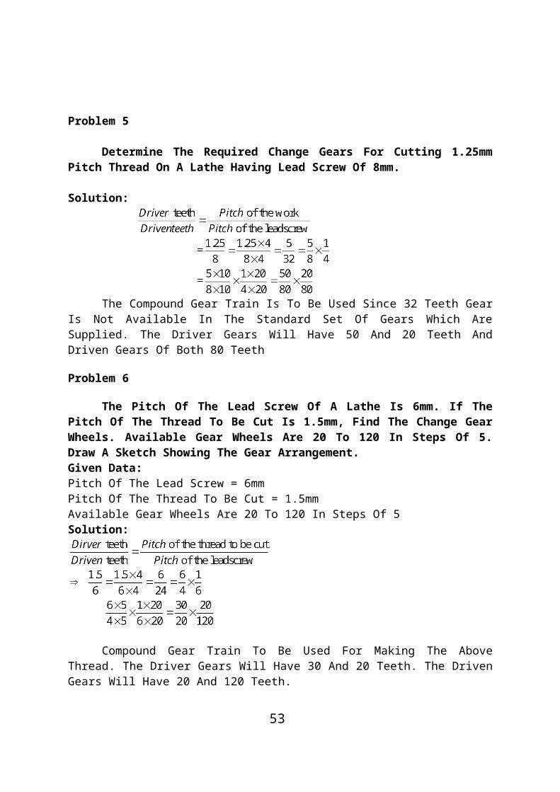
Problem 5
Determine The Required Change Gears For Cutting 1.25mm Pitch Thread On A Lathe Having Lead Screw Of 8mm.
Solution:
The Compound Gear Train Is To Be Used Since 32 Teeth Gear Is Not Available In The Standard Set Of Gears Which Are Supplied. The Driver Gears Will Have 50 And 20 Teeth And Driven Gears Of Both 80 Teeth
Problem 6
The Pitch Of The Lead Screw Of A Lathe Is 6mm. If The Pitch Of The Thread To Be Cut Is 1.5mm, Find The Change Gear Wheels. Available Gear Wheels Are 20 To 120 In Steps Of 5. Draw A Sketch Showing The Gear Arrangement.Given Data:Pitch Of The Lead Screw = 6mmPitch Of The Thread To Be Cut = 1.5mmAvailable Gear Wheels Are 20 To 120 In Steps Of 5Solution:
45

Compound Gear Train To Be Used For Making The Above Thread. The Driver Gears Will Have 30 And 20 Teeth. The Driven Gears Will Have 20 And 120 Teeth.
Problem 7
Calculate The Time Taken To Turn A Brass Component 75mm Diameter And 125mm Long If The Cutting Speed Is 52m/Min And The Feed Is 0.8mm/Rev. Only One Cut Is To Be Considered.
Given Data:D = 75mmL = 125mmV = 52m/MinF = 0.8mm/Rev
Solution:
Problem 8
Calculate The Time To Face A Work Piece Of 80mm Diameter. The Spindle Speed Is 115rpm And Cross Feed Is 0.4mm/Rev
Given Data:D = 80mmN = 115rpmF = 0.4mm/RevSolution:
Problem 9
Calculate The Number Of Teeth On Change Gears To Cut A
46

Mild Start Thread Of Having 4 Starts And Pitch 1.25mm. The Pitch On The Lead Screw Is 8mm.
Given Data:N = 4P = 1.25Pitch Of The Lead Screw = 8mm
Solution:
Therefore, The Driver Will Have 25 Teeth And Driven Will Have 40teeth.
Problem 10
A Shaft Of Diameter 60mm Is To Be Turned On A Lathe At A Cutting Speed Of 45m/Min. Find The Required Rpm Of The Shaft.
Given Date:V = 45m/MinD = 60mm
To Find:Speed In RpmSolution:
Problem 11
Calculate The Time Required For One Complete Cut On A Piece Of Work Having 250mm Long And 40 Mm Diameter. The Cutting Speed Is 32m/Min And The Feed Is 0.4 Mm/Rev.
Given Data:
47

L = 250 MmD = 40mmV = 32m/MinF = 0.4mm/Rev
Solution:
TOOLING
1. Simple Tool Layouts
Turret And Capstan Lathes Are Mainly Used For Machining Workpieces On A Rapid Rate. Before Starting The Production, The Following Works Are Carried Out
1. Selection Of Tools2. Designing Of Special Tools3. Selection Of Speeds4. Selection Of Feeds5. Setting The Required Length Of Work Piece And Tool Travel
Length.
These Planning Of Operation Sequence And Preparation Of Turret Of Capstan Are Termed As Tool-Layout. The Accuracy And Cost Of Product Are Largely Dependent On An Efficient Tool Layout. The Tool Layout Mainly Consists Of Three Stages.
1. Planning And Scheduling Stage: Preparation Of Operation Sheet With Order Of Operation.
48

2. Detailed Sketching Of Various Stages Of Machining Operations In Sequence Of Operations.
3. Sketching The Plan Showing The Various Tools Into The Hexagonal Turret Face And Cross Slides With Proper Sequence.
2. Step By Step Procedure For Preparing Tool Layout Of Turret And Capstan Lathe In Detail As Below
1. The Component To Be Machined Is Thoroughly Studied And The Required Total Length Of The Work Is Calculated.
2. The Number Of Operations Involved In The Component Starting From The Right End Is Roughly Listed.
3. From The Rough List Of Operations, The Proper Operation Se-quence Is Decided.
4. Various Tools According To The Sequence Of Operations Are Se-lected.
5. The Selected Tools Are Fitted Either Or Hexagonal Turret Or On Cross-Slide According To The Operation Sequence.
6. The Proper Cutting Speeds, Feeds And Depth Of Cut For Each And Every Operation Are Selected.
7. The Total Time Required Per Piece Is Determined. The Total Time Includes The Following Time Terms.A. Total Machining Time Of Each And Every Operations.B. Idle Time Between Successive Operations And
C. Time Required For Loading And Unloading The Components.8. The Detailed Drawing Of The Work Piece Is Drawn Along With The
Turret Tools And Cross-Slide Tools In Position.
The Above Procedure Can Be Recorded Either On A Plain Paper Or On A Simplified Process Planning Sheet Called Operation Sheet Or Process Layout.
Before Doing The Actual Layout, The Tool Designer Should Be Familiar In The Filed Of Capstan And Turret Lathes Tools, And Operations.
3. Solved Examples On Tooling.
Problem 12
A Tool Layout Is Prepared For The Manufacture Of Square Headed Bolt From A Square Bar Stock Using A Turret Lathe As Shown In Figure.
Solution:
49

Stage I:-
1. The Component Drawing Is Drawn2. The Total Length Of The Work Is Calculated And 10mm Is Added
To Provide Clearance.3. The Number Of Operations Involved Is Roughly Listed.4. The Sequence Of Operation Is Assigned.5. The Proper Machine Of 75mm Turret Lathe Is Selected.6. The Proper Material Of Mild Steel Square Bar Is Selected.7. All The Tools And Equipments As Per Operation Sequence Are Col-
lected And Fitted On Turret Faces Or On Cross Slides As Per Out Convenience.
Stage Ii:-
1. The Tool Layout Is Drawn As Shown In Figure
[Note: Number Tools Fitted In The Turret Face Are Only Four. So, For Providing Uniform Balancing Tools Are Arranged Like The First Two Are In Successive Faces And Other Two Are In Next Successive Faces By Leaving One Face Left To Free]
Stage Iii:-
Tooling Schedule Chart (To Machine Square Bolt)
Machine : 75mm Turret LatheMaterial: Square Mild Steel Bar
Operation
Sequence
Description Of Operation Tool Position
Tools
50

1.
Holding The Square Bar In Collet And Setting The Required Length Of 100mm (90+10)
Turret Positions
Bar Stop
2.Turn To 20mm Diameter To A Length 70mm (From The Right End)
Turret Position – 2
Roller Steady Box Turning Rod
3.Form The Right End Of The Bolt
Turret Position – 3
Roller Steady Bar Ending Tool.
4
Make The External Thread Cutting Of 20mm Diameter To A Length Of 40mm (From The Right End)
Turret Position – 4
Self Opening Die Head With Chases Of 20mm
5Chamfering The Bolt Head. Front Cross
Slide Tool Post-1
Chamfering Tool
6.
Parting Off The Work Piece Rear Tool Post
Parting Tool Is Placed In Inverted Position (Making The Rotation Of Work Anticlockwise With Respective To Tool)
Description Of Operations To Be Performed
I. Setting The Bar Stop:
The Bar Stop (1) Is Set At The Distance Of 100mm From The Collect Face By Using Slip Gauge. An Extra Length Of 10mm Is Allowed For Parting Off (4mm) And Clearance Off The Collect Face (6mm). This Clearance Is Allowed To Penetrate The Parting Tool Deep Into The Work Piece Without Any Interface.
Ii. Setting Of The Roller Steady Box Turning Rod:
This Tool Is Set On Turret Face Of 2. This Tool (2) Is Used For Turning The Work Piece To 200mm Diameter And 80mm Long From The Right End.
Iii. Setting Of Bar Ending Tool:
This Tool Is Set (3) On Fourth Turret Face But Turret Position-3. This Is Used To Chamfer The Right End Of The Work Piece.
Iv. Setting Self Opening Die Head:
51

This Tool (4) Is Set On The Fifth Face Of The Turret. The Proper Blades Of Chasers Are Selected And Fitted Into The Die Head To Cut A Thread Of 20mm Diameter.
V. Setting Of Chamfering Tool:
This Tool (5) Is Set On The Cross-Slide Front-End Position-1 Used To Chamfer The Bolt Head Edges By Giving Cross Feed.
Vi. Setting Of Parting Tool:
This Tool Is Set On The Rear End Of Cross-Slide. It Is Used To Part Off The Work Piece After Completing All Operations.
Note: Distance Of Each Tool Movement Is Set By Positioning The Stop With The Help Of Slip Gauges]
Problem 13
Draw The Tool Layout For Manufacturing Knurled Screw And Nut As Shown In Figure On Turret Lathe.
Solution:
Stage I:
1. The Component Drawing Is Drawn.2. The Total Length Of The Work Is Calculated And 10mm Is Added
To Provide Clearance3. The Number Of Operations Is Listed4. The Sequence Of Operation Is Listed5. The Proper Machine Of 75mm Turret Lathe Is Selected.6. The Proper Material Of Mild Steel Square Bar Is Selected.7. All The Tools And Equipments As Per Operation Sequence Are Col-
lected And Fitted On Turret Faces Or On Cross-Slides As Per Our Convenience.
Stage Ii:-
52
1. The Tool Layout Is Drawn As Shown In Figure
Note: Number Tools Fitted In The Turret Face Are Only Four. So, For Providing Uniform Balancing Tools Are Arranged Like The First Two Are In Successive Faces And Other Two Are In Next Successive Faces By Leaving One Face Left To Free]
Stage Iii:-
Tooling Schedule Chart (To Machine Given Component)
Machine: 75mm Turret Lathe
Material: Square Mild Steel Bar.
Operation
Sequence
Description Of Operation Tool Position Tools
1.
Holding The Square Bar In Collect And Setting The Required Length Of 47mm (37+10)
Turret Position. 1
Bar Stop
2.Turn To 10mm Diameter To A Length 37mm (From The Right End)
Turret Position. 2
Roller Steady Box-Turning Rod.
3.
Turn To 5mm Diameter And Form The Right End Of The Bolt For A Length Of 25mm And Form The End
Turret Position. 2
Roller Steady Bar Ending Tool
4.
Make The External Thread Cutting Of 5mm Diameter To A Length Of 23mm(From The Right End)
Turret Position. 3
Knurling Tool Holder With Knurls
53

5.Knurling On The Required Length
Turret Position.4
Knurling Tool Holder With Knurls
6.Chamfering The Bolt Head On 10mm Diameter
Front Cross Slide Tool Post Position
Chamfering Tool
7. Parting Off The ScrewRear Cross Slide. 1
Parting Tool
8. Drill And Face The NutTurret Position. 5
Drill And Facing Tool
9. Threading By TapTurret Position.6
Tap
10. Parting Off The Nut Rear Tool Post
Parting Tool Placed In Inverted Position (For Making The Rotation Of Work Anticlockwise With Respective To Tool Movement)
Description Of Operations To Be Performed
I. Setting The Bar Stop:
The Bar Stop (1) Is Set At The Distance Of 47mm From The Collect Face By Using Slip Gauge. An Extra Length Of 10mm Is Allowed For Parting Off (4mm) And Clearance Off The Collect Face (6mm). This Clearance Is Allowed To Penetrate The Parting Tool Depth Into The Work Piece Without Any Inference.
Ii. Setting Of The Roller Steady Box Turning Rod:
This Tool Is Set On Turret Face Of 2. This Tool (2) Is Used For Turning 10mm Diameter To A Length 37mm (From The Right End)
Iii. Setting Of The Roller Steady Box Turning Rod:
This Tool Is Set On Turret Face Of 2. This Tool (3) Is Used For Turning 5mm Diameter To A Length 25mm (From The Right End) And The Right End Of The Work Piece Is Formed.
Iv. Setting Self Opening Die Head:
This Tool (4) Is Set On The Third Face Of The Turret. The Proper Blades Of Chasers Are Selected And Fitted Into The Die Head To Cut A Thread Of 20mm Diameter.
54

V. Setting Of Knurling Tool:
This Tool (5) Is Set On The Turret Position – 4 Which Is Used To Knurled Portion On The Bolt Head.
Vi. Setting Of Chamfering Tool:
This Tool Is Set At The Front End Of The Cross-Slide Position2. It Is Used To Chamfer 10mm Diameter.
Vii. Setting Of Parting Off Tool:
This Tool Is Set On The Rear End Of Cross-Slide Position 1. It Is Used To Part Off The Screw.
Viii. Setting Of Drilling And Form Parting Off Tool:
This Tool Is Set On The Turret Position – 5 Used For Drilling And Facing The Nut.
Ix. Setting Of Thread Chasers:
This Tool Is Set On The Turret Position – 6 Used To Make Internal Threads Using Chasers.
X. Setting Of Parting Off Tool:
This Tool Is Set On The Rear End Of Cross-Slide Position 2. It Is Used To Part Off The Nut.
[Note: Distance Of Each Tool Movement Is Set But Positioning The Stop With The Help Of Slip Gauges]
14. Comparison Of Parallel Action And Progressive Action Multi-Spindle Automatic Lathes
Sl No.
Parallel Action Machine Progressive Action Machine
1. Same Operation Is Done On Different Operations Are Done On Jobs At
55

All Jobs In All The Spindles Each Station One After Another.2. In One Cycle, The Number
Of Components Produced Simultaneously Is Equal To The Number Of Spindles
It Is Not So,(I.E.) The Number Of Components Produced In One Cycle Is Not Equal To The Number Of Spindles. For Every Indexing Of Component (Spindle),One Component Is Produced
3. Rate Of Production Is Very High
Rate Of Production Is Moderate
4. If Anything Goes Wrong In One Station, The Production In That Particular Station Only Is Affected.
If Anything Goes Wrong In One Station, The Production Is Completely Affected In All The Stations.
5. Small Parts Of Simple Shapes Are Produced.
Parts Of Complicated Shapes Can Be Produced.
15. Comparison Of Single Spindle And Multi Spindle Automatic Lathes
Sl No
Single Spindle Multi Spindle
1. There Is Only One Spindle There Are 2, 4, 5, 6, Or 8 Spindles
2.Only One Work Piece Is Machined At A Time
A Number Of Work Pieces Are Machined At A Time.
3.The Rate Of Production Is Low
The Rate Of Production Is High
4.Machining Accuracy Is Higher.
Machining Accuracy Is Lower
5. Tool Setting Time Is Less Tool Setting Time Is More6. Tooling Cost Is Less Tooling Cost Is More
7.It Is More Economical For Shorter As Well As Longer Runs.
It Is More Economical For Longer Rungs Only.
8.
The Time Required To Produce One Component Is The Sum Of All The Turret Operation Times
Time Required To Produces One Component Is The Time Of The Longest Cut In Any One Spindle.
9.Tools In Turret Are Indexed
Work Pieces Held In Spindles Are Indexed (Progressive Action Machine)
56

UNIT – III
MACHINE TOOLS
PART – A
One Pass Of The Cutting Tool.
The Combination Of One Forward And One Return Stroke Is Known As One Pass.
Stroke, The Speed Of The Ram Is Faster
57

Return Stroke.
Cutting Ratio Of A Shaper.
The Ratio Between The Cutting Stroke Time To Return Stroke Time,
Two Types Of Quick Return Mechanism.
1. Hydraulic Drive Mechanism.2. Crank And Slotted Lever Mechanism.
The Feed And Depth Of Cut Is Given To The Shaper
Feed Is Given By Rotating The Down Feed Screws Of Tool Head Depth Of Cut Is Given By Rotating By Raising Or Elevating The Table.
The Various Types Of Flat Surface Produced On A Shaper.
1. Horizontal Surface2. Vertical Surface3. Inclined Surface
The Various Types Of Shaper According To Various Conditions
Generally, Shapers Are Classified As Follows.1. According To The Type Of Driving Mechanism.a. Crank Drive Typeb. Whit Worth Driving Mechanism Type.c. Hydraulic Drive Type2. According To The Position Of Ram.a. Horizontal Shaper.b. Vertical Shaperc. Traveling Head Shaper3. According To The Table Designa. Standard Or Plain Shaperb. Universal Shaper4. According To The Type Of Cutting Strokea. Push Out Typeb. Draw Cut Type
The Other Type Of Shaper
58

1. Standard Or Plain Shaper2. Universal Shaper3. Draw Cut Shaper.
Four Shaper-Specifications.
1. Maximum Length Of Stroke2. Type Of Driving Mechanism3. Power Of The Motor4. Speed And Feed Available
The Apron Is Fitted Away From The Machined Surface During Machining
The Apron Is Fitted Away From The Machined Surface To Avoid Rubbing Of The Tool On The Work Surface.
The Important Part To Control And Divert The Flow Of Oil Into The Cylinder In Hydraulic Drive.
Four – Way Valve.
Two Advantages Of Hydraulic Drive.
1. Higher Cutting To Return Ratio Can Be Obtained.2. Infinite Range Of Cutting Speeds Is Available.
The Type Of Mechanism Followed On A Shaper And Have It Works.
Rock And Pinion Mechanism Is Used. The Rotary Motion Of Electric Drive Is Converted Into Reciprocating Motion Of The Ram By Using Gears And Slotted Link.
The Precautions Of To Be Carried Out Before Machining Any Surfaces
1. Position Adjustment And2. Stroke Length Adjustment.
Two Reasons For Making The Stroke Length Greater Than Work Length.
1. If The Crank Pin Is Adjusted In Such A Way From The Centre Of The Bull Gear, The Rocker Arm Reciprocates For A Larger Dis-tance, So, The Stroke Length Is Increased.
59

2. The Stroke Length Should Always Be Greater Than The Work Length. I.E. Some Amount Of Approach And Over Run Should Be Provided To The Tool Movement.
The Types Of Feed
1) Hand Feed 2) Automatic Feed
Four Types Of Work Holding Devices.
1. Vice 2. Table 3. V-Block4. Fixture
The Various Types Of Tool
The Tools Are Classified As Below:1. According To The Shape.a. Straight Tool.b. Cranked Tool.c. Goose Necked Tool.
2. According To The Direction Of Cuttinga. Left Hand Tool.b. Right Hand Tool.
3. According To The Finish Required a. Roughing Toolb. Finishing Tool
4. According To The Type Of Operationa. Down Cutting Toolb. Parting Off Toolc. Squaring Toold. Side Recessing Tool.
5. According To The Shape Of The Cutting Edge.a. Round Nose Toolb. Square Nose Tool.
Any Four Operations Performed By A Shape.
1. Machining Horizontal Surfaces2. Machining Vertical Surfaces3. Machining Inclined Surfaces.
60

4. Machining Irregular Surfaces
The Tool Is Fitted On The Tool Head For Machining Inclined Surfaces
The Tool Is Set At Required Angle On The Tool Head Position And Stroke Lengths Are Adjusted And Also Proper Cutting Speed And Feed Are Chosen. The Apron Is Et Away From The Machining Surface. Depth Of Cut And Feed Are Given The Same As That The Machining Vertical Surface.The Dovetail Is Machined
To Make Dovetail, The Vertical Slide With Right Hand Tool Is At The Required Angle On Right Side Of The Work. Just Giving Feed And Depth Of Cut, The Right Side Dovetail Is Finished. Then The Vertical Slide With Left And Tool Is Set The Required Angle On Left Side Of The Work. Here Also Just By Giving Feed And Depth Of Cut. The Left Side Dovetail Is Finished.
The Various Types Of Recessing That Can Be Made By The Shaper
1. Grooves 2. Slots And 3. Key Ways
The Feed And Depth Of Cut Are Given To The Shaper While Machining Irregular Surfaces
For Machining Irregular Surface, A Round Nose Tool Is Set On The Tool Head. By Giving Both The Cross Feed And Vertical Feed At The Same Time The Irregular Surface Is Obtained. The Cross Feed In Given Through The Table And The Vertical Feed Is Given By The Tool Head, The Apron Is Fitted To Some Angle Away From The Machined Surface To Avoid Rubbing Of The Tool On The Work During Return Stroke.
Feed And Depth Of Cut.
1. Feed (F)The Relative Movement Of Tool With Respect To The Work Piece
Axis Is Known As Feed. 2. Depth Of Cut (T):
Amount Of Metal Removed In One Revolution Or In Cut Is Known As Depth Of Cut.
Write Down The Formula For Calculating No. Of Strokes And
61

Passes Required In A Shaper.
No. Of Strokes Required (SN)The Ratio Between The Width Of The Work And Feed Per Stroke.
The Metal Removal Rate.
Metal Removal Rate (W):The Volume Of Metal Removed Per Unit Time.Mmr (Or) W=Ftls
Planer Differs From A Shaper
In Planner:- The Work Reciprocates While The Tool Is Stationary.In Shaper:- The Tool Reciprocates While The Work Is Stationary.
The Cross Feed And Vertical Feed Are Given In The Planner
The Cross Feed Is Given By Moving The Tool Head Along The Cross Rail And The Vertical Feed Is Given By Moving Down The Tool.
The Uses Of Planer.
The Planer Is Used For Machining Heavy And Large Casting. Ex. Lathe Bed Guide Ways, Machine Guide Ways Etc.
The Various Types Of Planners.
1. Double Hosing Planer2. Open Side Planer3. Pit Planer4. Edge Planer5. Divided Table Planer
The Various Parts Of A Double Housing Planner.
1. Bed2. Table
62

3. Columns4. Cross Rail5. Tool Head
The Main Difference In Open Side Planer
The Only Difference In The Type Is Only One Vertical Column Is Provided On One Side Of The Bed And Other Side Is Left Free.
The Main Advantages Of Using Pit Planer.
Heavy And Large Work Can Be Held And Machined Easily.
Special Provision Made In Edge Planner
Yes. A Platform Is Provided To Stand And Travel Along With It While Machining.
The Main Difference Made In Divided Table Planer
The Working Principle Is Similar To That Of A Standard Planer. But It Has Two Reciprocating Tables.
Four Specifications Of Planer.
1. Maximum Length Of The Table.2. Total Weight Of The Planer.3. Power Of The Motor.4. Range Of Speeds And Feed Available5. Type Of Drives Required.
The Function Of Clapper Block In A Planer
During Cutting Stroke, The Tool Block Fits Inside The Clapper Block Rigidly. During The Return Stroke, The Tool Block Lifts Out Of The Clapper Block To Avoid Rubbing Of The Tool On The Job.The Various Types Of Quick Return Mechanism
1. Open And Cross Belt Drive 2. Electric Drive3. Hydraulic Drive
The Various Quick Return Motion Mechanism Used In Slotter.
1. Whitworth Quick Return Mechanism.2. Variable Speed Reversible Electric Motor Drive.
63

3. Hydraulic Drive.
The Difference Speeds Available In Slotter.
a. Longitudinal Feed b. Cross Feedc. Circular Feed
The Operations That Can Be Performed On A Slotter
I. Machining Flat Surface.II. Machining Grooves, Slots, Key Ways.
III. Machining Irregular Surface.
“Milling Process”.
Milling Is The Process Of Removing Metal By Feeding The Work Past A Rotating Multipoint Cutter.
The Specifications Of Milling Machine
1. The Table Length And Width.2. Maximum Longitudinal Cross And Vertical Travel Of The Table.3. Number Of Spindle Speeds And Feeds.4. Power Of Driving Motor.5. Floor Space And Net Weight.
Milling Machine.
1. Column And Knee Types
a. Plain Milling Machineb. Vertical Milling Machine.c. Universal Milling Machined. Ram-Type Milling Machinee. Universal Milling Machine.
2. Bed-Type Milling Machinea. Simplex Milling Machine.b. Duplex Milling Machine.c. Triplex Milling Machine.
3. Plano – Type Milling Machine4. Special Purpose Milling Machine
64

a. Rotary Table Milling Machineb. Drum Milling Machine.c. Profile Milling Machine.
The Two Types Of Column And Knee Type – Milling Machine
i.Horizontal Type.ii. Vertical Type.
The Principle Parts Of Horizontal Or Plain Milling Machine.
Base. Column, Knee, Saddle, Table, Over Arm, And Arbor.
The Various Movements Of Universal Milling Machine Table.
1. Vertical Movement – Through The Knee.2. Cross Wise Movement-Through The Saddle.3. Longitudinal Movement Of The Table.4. Angular Movement Of The Table –By Swiveling The Table The
Swivel Base.
Two Comparison Between Plain And Universal Milling Machine.
1. In Plain Milling Machine, The Table Is Provided With Three Movements, Longitudinal, Cross And Vertical. In Universal Milling Machine In Addition To These Three Movement There Is A Fourth Movement To The Table. The Table Can Swiveled Horizontally And Can Be Fed At Angle To The Milling Ma-chine Spindle.
2. The Universal Milling Machine Is Provided With Auxiliaries Such As Dividing Head, Vertical Milling Attachment, Rotary Table Etc. Hence It Is Possible To Make Spiral, Bevel Gears Twist Drills, Reamers Etc On Universal Milling Machine.
Universal Milling Machine Differs From Universal Milling Machine
This Is A Modified From Of Plan (Horizontal) Milling Machine. It Is Provided With Two Spindles, One Of Which Is In The Horizontal Plane While The Other Is Carried By A Universal Swiveling Head.
Bed Type Milling Machine.
The Bed Type Milling Machines Are Classified As Simplex, Duplex And Triplex Machine.
65

The Different Ways For Machining Workpieces In Plano- Milling
a. By Moving The Table, The Cutters Rotating In Position.b. By Keeping The Table Stationary And Feeding The Cutters By Mov-
ing The Milling Heads.c. By Moving The Table And The Milling Heads Simultaneously.d. By Keeping The Table Stationary Mving The Cross-Rail Down
Wards And The Side Cutters Up And Down.
The Various Types Of Special Purpose Milling Machine
1) Rotary Table Or Continuous Milling Machine2) Drum Type Milling Machine 3) Profile Or Count On Milling Machine
Four Important Types Of Work Holding Devices.
(a)N Blocks(b)Machine Vises.(c) Milling Fixture(d)Dividing Heads
The Cutter Holding Devices
1. Arbors.2. Adaptors3. Collets
The Two Types Of Arbor
(i) Standard Arbor.(ii) Stub Arbor.
Various Types Of Milling Attachments.
(i) Vertical Milling Attachment(ii) Universal Milling Attachment(iii) High Speed Milling Attachment(iv) Rotary Attachment(v) Slotting Attachment(Vi) Rack Milling Attachment(Vii) Universal Spiral Milling Attachment
Milling Cutters.
66

According To The Shape Of The Tooth, Milling Cutters Are Classified As
(i) Milled Tooth Cutters(ii) Form Relieved Cutters
According To The Types Of Operation.
(i) Plain Milling Cutters(ii) Side Milling Cutters(iii) End Mill Cutters(iv) Angle Milling Cutters(v) T-Slot Milling Cutters(vi) Slitting Saws(vii) Form Milling Cutters(viii) Flu Cutters(ix) Wood Ruff Key Slot Milling Cutter
According To The Way Of Mounting On The Machine
(i) Arbor Cutters(ii) Shank Cutters(iii) Face Cutters
Ten Nomenclature Of Plain Milling Cutter.
Body Of Cutter, Cutting Edge, Face, Filter, Gash, Lead, Land, Outside Diameter. Roof Diameter, Cutter Angles.
The Two Main Group Of Milling Processes
i. End Millingii. Face Milling
Peripheral Milling Processes.
i. Up Milling Or Conventional Milling Andii. Down Milling Or Climb Milling
The Rotation Of Cutter With Respect To Workplace Movement In Up Milling
The Cutter Rotates Opposite To The Direction Of Feed Of The Work Piece
67
The Advantages Of Up Milling Process
1. Safer Operation Due To Separating Forces Between Cutter And Work
2. Less Wear On Feed Screw And Nut Due To The Absence Of Pre-Loaded
3. Milled Surface Does Not Have Built Up Edge
Climb Milling Differs From Conventional Milling
The Cutter Rotates In The Same Direction Of Travel Of The Work Piece
The Advantages Of Down Milling Process
(i) Cutter With Higher Take Angles Can Be Used. This Reduces Power Requirements.
(ii) Cutter Wear Is Less Because Chip Thickness Is Maximum At The Start Of The Cut.
(iii) Finishing Is Generally Good Because The Rubbing Action With Chip Is Eliminated.
The Differences Between Up Milling And Down Milling Sl.No `Event Of
OperationUp Milling Down Milling
(I) Direction Of Travel
Cutter Rotates Against The Direction Of Travel
Of Work Piece
Cutter Rotates In The Same Direction Of Travel Of Workpiece.
(II) Chip Thickness Minimum At The Beginning Max When The Cut Terminates
Maximum At The Beginning Greeches Min
At Terminates (Iii) Cutting Force Increases From Zero To
Max Per ToothDecreases From Max To
Zero Per Tooth
Face Milling”.
Face Milling Is The Operation Performed By A Milling Cutter To Produce Flat-Machined Surfaces Perpendicular To The Axis Of Rotation.
The Various Milling Operations.
1. Plain Or Slab Milling.2. Face Milling
68

3. Angular Milling4. Straddle Milling5. Gang Milling6. Form Milling.7. End Milling.8. T-Slot Milling.9. Gear Cutting.
Plain Or Slab Milling
Plain Or Slab Milling Is The Operation Of Producing Flat Horizontal Surface Parallel To The Axis Of The Cutter Using A Plain Or Slab Milling Cutter.
The Following Terms: Straddle Milling And Gang Milling.
Straddle Milling Operation Is The Production Of Two Vertical Flat Surfaces On The Both Sides Of The Job By Using Two Side Milling Cutters Which Are Separated By Collars.
Term Indexing
Indexing Is The Process Of Diving The Periphery Of A Job Into Equal Number Of Divisions.
Three Types Dividing Heads
1. Plain Or Simple Dividing Head.2. Universal Dividing Head.3. Optical Dividing Head.
Two Stage In Differential Indexing
Stage 1: The Crank Is Moved In A Certain Direction.Stage 2: Movement Is Added Or Subtracted By Moving The Plate By Means Of A Gear Train.
The Rule For Gear Ratio In Differential Indexing,
Rule For Gear Ratio In Differential Indexing:
Gear Ratio=
A Selected No Which Can Be Indexed By Plain Indexing And Approximately Equal To N.N Required No Of Divisions To Be Indexed.
69

Sl.No
`Event Of Operation
Up Milling Down Milling
(I) Direction Of Travel
Cutter Rotates Against The Direction Of Travel Of Work Piece
Cutter Rotates In The Same Direction Of Travel Of Workpiece.
(II) Chip Thickness Minimum At The Beginning Max When The Cut Terminates
Maximum At The Beginning Greeches Min At Terminates
(Iii) Cutting Force Increases From Zero To Max Per Tooth
Decreases From Max To Zero Per Tooth
“Face Milling”.
Face Milling Is The Operation Performed By A Milling Cutter To Produce Flat-Machined Surfaces Perpendicular To The Axis Of Rotation.
The Various Milling Operations.
1. Plain Or Slab Milling.2. Face Milling3. Angular Milling4. Straddle Milling5. Gang Milling6. Form Milling.7. End Milling.8. T-Slot Milling.9. Gear Cutting.
Plain Or Slab Milling
Plain Or Slab Milling Is The Operation Of Producing Flat Horizontal Surface Parallel To The Axis Of The Cutter Using A Plain Or Slab Milling Cutter.
Straddle Milling And Gang Milling.
Straddle Milling Operation Is The Production Of Two Vertical Flat Surfaces On The Both Sides Of The Job By Using Two Side Milling Cutters Which Are Separated By Collars.
Term Indexing
Indexing Is The Process Of Diving The Periphery Of A Job Into Equal Number Of Divisions.
70

Three Types Dividing Heads
1. Plain Or Simple Dividing Head.2. Universal Dividing Head.3. Optical Dividing Head.
Two Stage In Differential Indexing
Stage 1: The Crank Is Moved In A Certain Direction.Stage 2: Movement Is Added Or Subtracted By Moving The Plate By Means Of A Gear Train.
The Rule For Gear Ratio In Differential Indexing, (Anna Uni Nov ’03)
Rule For Gear Ratio In Differential Indexing:
Gear Ratio=
A Selected No Which Can Be Indexed By Plain Indexing And Approximately Equal To N.N Required No Of Divisions To Be Indexed.
The Combination Of Two Movements Takes Place In Differential Indexing
When The Index Plate Rotates In The Same Direction Of The Crack The Resulting Movement Of The Crank Will Increase. When The Index Plate Rotates In The Opposite Direction Of The Crank, The Resulting Actual Movement Is Decreased.
Drilling
Drilling Is The Process Of Producing Hole On The Work Piece By Using A Rotating Cutter Called Drill.
Drilling Machines.
The Drilling Machines Are Classified As Follows:1. Portable Drilling Machine.2. Sensitive Drilling Machine.a) Bench Typeb) Floor Type
3. Upright Drilling Machines
71

a. Round Column Type Or Square Section Type.b. Box Column Type Or Pillar Type
4. Radial Drilling Machinea. Plain Type b. Semi-Universal Typec. Universal Type
5. Gang Drilling Machine6. Multiple Spindle Drilling Machine7. Automatic Drilling Machine8. Deep Hole Drilling Machine
The Various Parts Of Sensitive Drilling Machines.
A. ColumnB. TableC. Spindle And Driving Mechanism
Drilling Machine Is A ________
Higher Capacity Version Of Sensitive Drilling Machine.
The Various Parts Of A Upright Drilling Machine.
a. Baseb. Columnc. Table And Spindle Headd. Driving Mechanism
The Main Components Of A Radial Drilling Machine
A. BaseB ColumnC. Radial ArmD. Drill Head E. Spindle Head And Feed Mechanism
The Various Types Of Drilling Machines
A. Plain TypeB. Semi-Universal C. Universal Type
The Main Use Of Multi-Spindle Drilling Machine
72

This Machine Is Suitable For Mass Production. In This Machine Several Holes Of Different Sizes Can Be Drilled Simultaneously.
Gang-Drilling Machine
When A Number Of Single Spindles With Essential Speed And Feed Are Mounted Side By Side On One Base And Have Common Workable, It Is Known As The Gang-Drilling Machine.
Radial Drilling Machine
A Drilling Machine Is Specified By The Following Items.1. Maximum Size Of The Drill In Mm That The Machine Can Operate.2. Table Size Of Maximum Dimensions Of A Job Can Mount On A Table
In Square Meter.3. Maximum Spindle Travel In Mm.4. Number Of Spindle Speed And Range Of Spindle Speeds In R.P.M.
Four Operations That Can Be Performed In A Drilling Machine.
1. Drilling2. Counter Sinking3. Tapping4. Trepanning
“Sensitive Hand Feed”
In Drilling Machine, Manual Sensing Of The Hand Does Feeding Of The Tool Towards The Work Piece. It Is Called Sensitive Hand Feed.
Calculate The Tap Drill Size To Cut An Internal Thread For Bolt Of Outside Diameter 10mm, And Depth Of The Thread 0.61 Pitch
Drill Size = Tap Size – 2 X Depth Of ThreadsDepth Of Threads = 0.61 X 1.5 = 0.915mmSo Drill Size = 10-2 X 0.915 = 8.17mm
Reaming
Reaming Is The Process Of Sizing And Finishing The Already Drilled Hole. The Tool Used For Reaming Is Known As Reamer.
1. Boring 2. Counter Boring 3.Spot Facing
73

4. Undercutting And 5. Honing
Drilling Tool
1. Body 2.Shank 3.Neck 4. Point 5. Land Or Margin
Different Ways To Mount The Drilling Tool
1. Fitting Directly In The Spindle.2. By Using A Sleeve 3. By Using A Socket4. By Means Of Chucks
The Reamer Tool Differs From Drilling Tool
A Reamer Is A Multi-Tooth Cutter Which Rotates And Moves Linearly In To An Already Existing Hole.
The Use Of A Tapping Tool
A Tap Is A Tool Which Used For Making Internal Threads In A Machine Component.
The Power Is Calculated In Drilling Operations
When A Drill Cuts It Should Overcome The Resistance Offered By The Metal And A Twisting Effort Is Necessary To Turn It. The Effort Is Called Torque On The Drill. The Torque Is Depending Upon The Various Factors. The Relation Between Torques Diameter Of Drill And Feed Is As Follows.
T = C X F0.75 X D18
Where, T = Torque In N-M F = Feed In Mm/Rev D = Diameter Of Drill C = Constant Depending Upon The Material Being
Power, P =
Where, N – Speed Of Drill In R.P.M.
Boring
Boring Is The Process Of Enlarging And Locating Previously Drilled Holes With La Single Point Cutting Tool.
74

The Applications Of Boring
The Boring Machine Is Designed For Machining Large And Heavy Work Piece In Mass Production Work Of Engine Frame, Cylinder Machine Housing Etc.
The Main Difference Between Boring Bar And Boring Tool
Boring Bar: The Tool Which Is Having Single Point Cutting Edge Known As Boring Bar.
Boring Tool: The Tool Which Is Having Multi Point Cutting Edge Known As Boring Tool.
The Types Of Boring Machines
The Boring Machines May Be Classified As Follows:1. Horizontal Boring Machinea. Table Typeb. Floor Type c. Planner Typed. Multiple Head Type
2. Vertical Boring Machine3. Precision Boring Machine4. Jig Boring Machine
The Work Is Clamped On The Table
The Work Piece Is Mounted On The Table And Clamped With Ordinary Strap Clamps T-Slot Bolts And Nuts Or It Is Held In A Special Boring Fixture If So Required.
MACHINING CALCULATIONS
1. Cutting Speed (V)
It Is The Velocity At Which The Metal Is Removed By The Tool.
75

Where, L – Length Or Cutting Stroke In Mm N – Speed In Rpm M - Ratio Between Cutting Time And Return Time
2. Feed (F)
The Relative Movement Of Tool With Respect To The Work Piece Axis Is Known As Feed.
Depth Of Cut (T)
Amount Of Metal Removed In One Revolution Or In Cut Is Known As Depth Of Cut.
Machining Time (T)
Time Required For Machining The Work Surface To The Required Dimensions.
Where,
L – Length Of Stroke = L+Approach + Over RunN – Speed In RpmF – FeedL – Work Piece LengthL/V – Time For Cutting StrokeMl/V – Time For Return Stroke
5. No. Of Strokes Required (SN) The Ratio Between The Width Of The Work And Feed Per Stroke
6. Total Machining Time (T)
76

The Time Required For Machining The Entire Surface Of The Work As Per Requirements.
7. Metal Removal Rate (W)
The Volume Of Metal Removed Per Unit Time. Mmr (Or) W = FtlsWhere, F – Feed T –Depth Of Cut L – Length Of Work S – Strokes Per Minute
8. Power Required
P = K X W Where, K – Machining Constant.
9. Number Passes:
SOLVED PROBLEMS
Problem 1
A Shaper Is Operated At 125 Cutting Strokes Per Minute And Is Used To Machine A Work Piece Of 300 Mm In Length And 125 Mm In Width. Use A Feed Of 0.6mm Per Stroke And A Depth Of Cut Of 6mm. Calculate The Total Machining Time For Machining The Component. The Forward Stroke Is Completed In 2300. Calculate The Percentage Of The Time When The Tool Is Not Contacting The Work Piece.
Given Data:
S = 125 Strokes/MinWork Piece Length, L = 300mmW = 125 MmF = 0.6mm/StrokeT =6mm
77

Forward Stroke Angle,
Solution
Let Us Assume The Approach And Over Run = 25mm Stroke Length L = L+25=300+25=325mm
Number Of Strokes,
Total Time For Completing One Stroke,
Total Machining Time,
Percentage Of Time When The Tool Is Not Contacting The Work Piece
But, The Angle Of Return Stroke
Problem 2
Calculate The Power Required For Shaping Stect With A Depth Of Cut Of 2.8mm, Cutting Speed 65m/Min And The Work Length 50mm. The Feed Rate Is 0.5mm/Rev. Take Machining Constant K As 70x10—6.Given Data:
T = 2.8mm
78

V = 65m/Min = 65x1000mm/MinL =50mmF = 0.5mm/Rev
Solution: Material Removal Rate, W = F T V = 0.5x2.8 X 65 X 1000 P = Kw
Power Required, P = 79 X 10-6+ X 91000 = 70189 H.P Ans = 7.189 X 0.736 = 5.29 Kw
Problem 3
Estimate The Shortest Machining Time Required In A Shaper To Machine A Plate Of 200 X 90 Mm Under The Following Conditions.Cutting Speed = 13.3m/MinFeed = 0.57 Mm/Double StrokeNumber Of Passes = OneApproach + Overrun (Longitudinal) =20mm(Lateral) = 4mmRatio Of Cutting Speed To Rapid Return = 0.83
Given Data:Cutting Speed, V = 13.3m/MinFeed, F = 0.5mm/Double StrokeNumber Of Pass, N=1Approach Over Run, A = 20mmWork Length, L = 200mmWork Width W = 90mmRatio M = 0.83
Solution:
79

= 220mm=0.22m
Total Time T =
Number Of Strokes SN =
Total Width = W+ Lateral Approach = 90+4 =94mm
SN =
Problem 4
The Cross-Feed On A Shaper Consists Of A Lead Screw Having 0.2 Threads Per Mm. A Ratchet And Pawl On The End Of The Lead Screw Is Driven From The Shaper Crank Such That The Pawl Indexes The Ratchet By One Tooth During Each Return Stroke Of The Ram. Ratchet Has 20 Teeth.
a) Find The Cross Feed In Mm.b) If A Plate 100 Mm Wide Has To Be Machined In 10 Minutes
Find The Cutting Speed In M/S. The Ratio Of Return To Cut-ting Speed Is 2:1 And The Length Of The Stroke Is 150mm.
Given DataLead Screw Threads = 0.2 Thread/MmRatchet Teeth = 20Plate Wide, W = 100 MmMachining Time, T = 10minRatio Of Return To Cutting Speed 1/M = 2Stroke Length L = 150mm
Solution
80

Pitch Of The Lead Screw =
Pawi Indexes
a) Cross Feed:F= Pawl Indexing X Lead Screw Pitch
Number Of Cutting Strokes,
SN =
Total Time Required To Complete The Job,
Tt = TXSN
= 10x400=400min
Cutting Speed, V =
Cutting Speed,
Problem 5
A 75cm X 20 Cm Surface Of Cast Iron Block Of 15 Cm Thick Is To Be Machined On A Shaper. Ram Speed Is 25mpm, Length Of Stroke Is 500 Mm, Depth Of Cut Is 4mm, Feed Id 1.5mm/Stroke Stock To Be Removed Is 7mm Side Cutting Edge Angle Of The Tool Is 450, Ratio Of Time Taken In Return Stroke To The Time Taken In Cutting Stroke Is 0.5. Determine The Metal Removal Rate And The Cutting Time.Given Data:Cast Iron Block Of 75 X 20 X 15 CmV = 25 Mpm
81

L = 500 MmT = 4mmF = 1.5mm/StrokeStock To Be Removed = 6mm
Solution
Metal Removal Rate W = F T L N = 1.5 X 4 X 500 X34 = 102 X 103 Mm3/Min
Number Of Passes N =
Problem 6: Direct Or Rapid Indexing
Find Index Movement To Mill Hexagonal Bolt By Direct Indexing If The Rapid Index Plate Has 24 Slots.
Solution:
Number Of Slots To Be Moved =
After Machining One Side Of The Bolt, Index Plate Has To Be Moved By 4 Slots For 5 Times To Finish The Work.
Problem 7: Compound Indexing
82
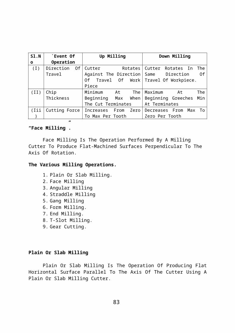
Compound Indexing For 87 Divisions.
Solution:
Required Movement Of The Work Piece =
Suppose We Select Two Circles Of 29 And 33 Holes. Substituting The Values In The Expression 3.1. (Refer Compound Indexing)
Since, The Numerator Is One, The Selected Circles Are Correct.
The Required Indexing Is Given By
Taking 3 As Common, The Above Expression Becomes
For Indexing, The Index Crank Should Be Moved By 23 Holes Of 29 Circle Forward Directions And Then The Plate And The Crank Together Is Moved By 11 Holes Of 33 Circles In Backward Direction.
Problem: 8
Compound Index For 69 Divisions.
Solution:
Required Index Movement =
83

Suppose, We Select Two Circles Of 23 And 33 Holes. Substitute The Values In Expression 8.1.
Since The Numerator Is Unity, The Circles Selected Are Correct. The Required Indexing Movement Is Given By
Taking 1 As Common, The Above Expression Become
Thus For Indexing 69 Divisions, The Index Crank Should Be Move By 21 Holes Of 23 Hole Circle In Forward Direction He Then The Plate And The Crank Together Is Moved By 11 Holes Of 33 Hole Circle In The Backward Direction.
Problem 9: Differential Indexing
Find Out The Indexing Movement Of Milling 119 Teeth Spur Gear On A Gear Blank.
Solution:Assume A = 120
A. Gear Ratio:
=
A Simple Gear Train Is Used.
84

Gear On Spindle Will Have 24 Teeth.
Gear On Bevel Gear Shaft Will Have 72 Teeth
B. Index Crank Movement:
The Index Crank Will Have To Be Moved By 8 Holes In 24 Hole Circle For Each Cut For 119 Times.
C Number Of Idlers:
As (A - N) Is Positive, A Simple Gear Train With One Idler Is Used. The Index Plate Will Rotate In The Same Direction Of The Crank Movement.
Problem 10
Calculate The Spindle Speed To Drill A Hole Of 50mm Using Cutting Speed As 25m/Min
Given Data:Diameter Of Hole, D = 50mmCutting Speed, V = 25m/Min
Solution:
Problem :11
85

Calculate The Feed In Mm/Rev To Drill A Hole Of 30mm In One Minute To A Plate Thickness Of 40mm And Using A Spindle Speed Of 500rpm.Given Data:
Diameter Of Hole, D = 30mmMachining Time, T = 1 MinuteThickness Of Plate, Tp = 40mmSpindle Speed, N = 500rpm
Solution:We Know That,
Machining Time, T =
Problem 12
Calculate The Machining Time Required For Making 15 Holes On A M.S. Plate Of 30mm Thickness With The Following Data:
Drill Diameter = 25 MmCutting Speed = 20m/Min And Feed = 0.13mm/Rev
Given Data :
Number Of Holes To Be Drilled = 15Thickness Of The Plate, Tp = 30mmDrill Diameter, D = 25 MmCutting Speed, N = 20m/MinFeed, F = 0.13mm/Rev
Solution:
We Know That
86

Total Machining Time, Tm = 6.66 X 15 = 9.99 Minute Ans.
Problem 13
A 40 Mm HSS Drill Is Used To Drill A Hole In A Cast Iron Black Of 80mm Thick. Determine The Time Required To Drill The Hole If Feed Is 0.2mm/Rev. Assume An Over Travel Of Drill As 5 Mm. The Cutting Sped Is 22m/Min.
Given Data:Drill Diameter, D = 40mmThickness Of C.I.Block = 80Feed, F =0.2mm/RevOver Travel, S = 5 MmCutting Speed, V = 22m/Min
Solution:
We Know That
Length Of Travel Of Drill = Tp +0.3D +Over Travel
87

= 80 + 0.3 X 40 + 5 = 97mm
Problem :14
Calculate The Power Required To Drill 25mm Diameter Hole In Aluminium Plate At A Feed Of 0.2mm/Rev And At A Drill Speed 400rpm. Determine Also The Volume Of Metal Per Unit Minute.
Given Data:Drill Diameter, D = 25
Material: Aluminium
Feed, F =0.2mm/Rev
Drill Speed, N = 400rpm
Solution:We Know That
From Table 3.1 For Aluminium, C = 0.11
Volume Of Metal Removal/Minute= Area Of Hole X Feed X Speed
=
= 32.27 X 103mm3 Ans.
88

Energy Consumption =
= 86.8m3/Watt Minute Ans.
Compare Peripheral Milling And Face Milling (MU Oct 1996)
What Are The Three Milling Processes
The Three Milling Process Are Face Milling, Slab Milling And End Milling.
In Face Milling, The Cutter Axis And The Work Piece Axis Intersect And The Cutting Teeth On The Periphery Does Not Do The Cutting.
In Slab Milling (Peripheral Milling) The Cutter Axis Do Not Intersect, It Has Teeth On The Periphery Only Which Does The Cutting.
In End Milling, Both The Face And The Periphery Does The Cutting Which Can Be Seen In The Figure. Thus End Milling May Be Said To Be A Combination Of Peripheral As Well As Face Milling.
Draw A Sketch Showing The End Mill Terminology.
Sketch A Milling Cutter And Indicate Rake, Clearance And Lip Angle. (MKU Nov 1996)
89

Though In The University Question Only The Sketch Of A Cutter Tooth And Few Parameters Are Asked. I Have Given A More Elaborate Figure Of The Entire Cutter For Better Understanding.Arbor- Shaft On Which The Milling Cutter Is Mounted And Driven.
Body- That Part Of The Cutter Left After Exclusion Of The Teeth And The Portions To Which The Teeth Are Attached.
Clearance Angles- Angles Formed By Primary Or Secondary Clearance And The Tangent To The Periphery Of The Cutter At The Cutting Edge. They Are Called The Primary And Secondary Clearance Angle Respectively.
Cutting Edge- Edge Formed By The Intersection Of The Face And The Circular Land Or The Surface Left By The Provision Of Primary Clearance.
Face- That Portion Of The Gash, Adjacent To The Cutting Edge On Which The Chip Impinges As It Is Cut From The Work.
Fillet- Curved Surface At The Bottom Of Gas Which Joins The Face Of One Tooth To The Back Of The Tooth Immediately Ahead.
Gash- Chip Space Between The Back Of One Tooth And The Face Of The Next Tooth And The Face Of The Next Tooth.
Land- That Part Of The Back Of Tooth Adjacent To The Cutting Edge. Which Is Relieved To Avoid Interference Between The Surface Being Machined And The Cutter.
Lead- Axial Advance Of The Helix Of The Cutting Edge In One Complete Revolution Of The Cutter.
Lip Angel- Included Angle Between The Land And The Face Of The Tooth, Or Alternatively The Angle Between The Tangent To The Back At The Cutters With The Shank, Between The Body And The Shank.
Outside Diameter- Diameter Of The Circle Passing Through The Peripheral Cutting Edge.
Rake Angle (Axial)- Angle Between The Line Of Peripheral Cutting Edge And The Axis Of The Cutter When Looking Radically At The Point Of Intersection.
90

Rake Angle (Radial) - Angle, In Plane Perpendicular To The Axis, Between The Face Of The Tooth And A Radial Line Passing Through The Cutter Edge.
Relief Angle – Angle In A Plane Perpendicular To The Axis, Between The Relieved Land Of A Tooth And The Tangent To The Outside Diameter Of Cutter At The Cutting Edge Of That Tooth.
Root Diameter – Diameter Of The Circle Passing Through The Bottom Of The Fillet. ]
Shank - Plain Parallel Or Tapered Extension Along The Axis Of The Cutter Employed For Holding And Driving.
Circumferential Form Relief – Clearance Produced On The Teeth By Reducing The Diameter Of The Entire Form From The Cutting Edge To The Heel Via Curve- Linear Fashion.
Circular Pitch- The Circular Distance Between The Adjacent Teeth Measured At The Periphery Of The Cutter.
Depth Of Form – The Depth Of Form Is The Difference Between The Radial Distance To The First And The Last Points Of The Cutting Edge.
91
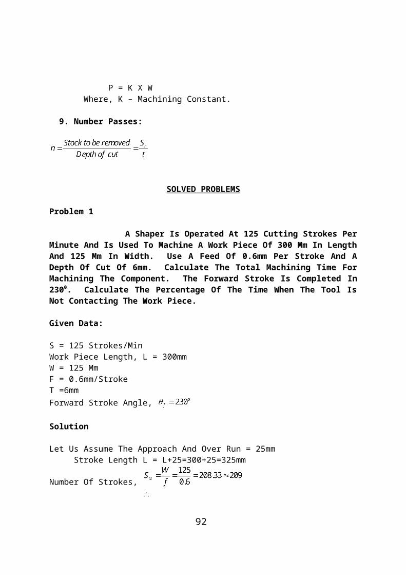
UNIT – IV
UNCONVENTIONAL MACHINING PROCESS
PART – A
Abrasive
It Is The Material Of The Grinding Wheel Which Does The Cutting Action.
Dressing.
The Process Of Removing The Leading And Breaking Away The Glazed Surface So That Fresh Sharp Abrasive Particles Are Again Presented To The Work For Efficient Cutting Is Called Dressing.
Truing
Truing Is The Process Of Changing The Shape Of The Grinding Wheel As It Becomes Worn From An Original Shape, Owing To The Breathing Away Of The Abrasive And Bond.
Counter Sinking.
It Is The Operation Of Making A Cone Shaped Enlargement Or Recess At The End Of A Hole. The Troll Used Is Called Counter Sink.
Trepanning
92
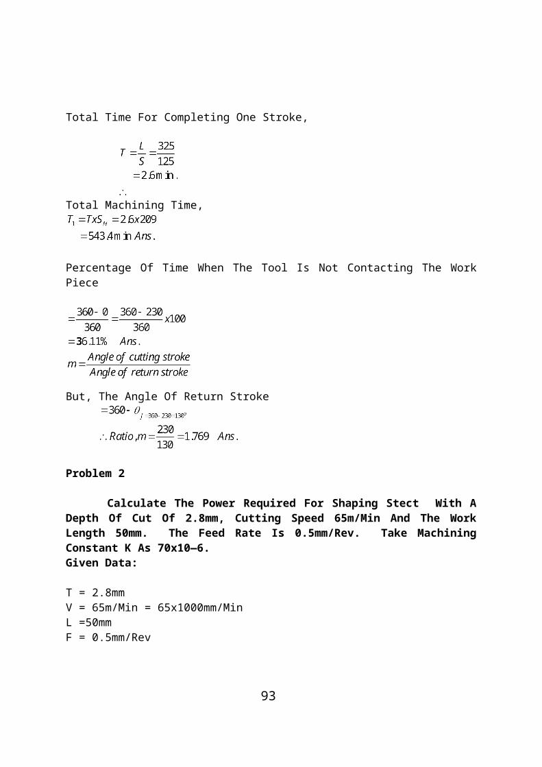
It Is An Operation Which Is Done When A Large Hole Is To Be Made In Thin Metal Or When A Very Deep And Large Hole Is To Be Made In A Solid Work Piece.
Reaming
Reaming Is The Operation Of Finishing A Hole Very Smoothly And Accurately In Size.
Grinding.
Grinding Is A Process Of Removing Material By The Abrasive Action Of Revolving Wheel On Surface Of A Work Piece In Order To Bring The Required Shape And Size.
The Standard Marking Systems For Grinding Wheel
Types Of Abrasives
Grain Size Grade Of The Wheel Structure Types Of Bond
Different Surface Finishing Processes.
Introduction
In A Manufacturing Plant, A Product May Be Shaped, Turned, Milled Or Drilled, And Left In Condition As Being Satisfactory For Use. However, If A Better Finish Is Desired, For Looks, For Accuracy, For Wearing Qualities, One Of The Micro-Finishes That Include Lapping, Honing, Super Finishing Buffing, Burnishing And Polishing May Be Employed. These Methods Remove Very Small Amount Of Metal And The Surface Finish Is Specified In Micro-Inches And Hence The Name Micro Finishes.
Lapping
It Is An Abrading Process For Refining Surface Finish And The Geometrical Accuracy Of Flat, Cylindrical And Spherical Surfaces. It Is A Process Of Removing Surface Roughness, Tool Marks, Surface Cracks From Grinding, Slight Distortions And Other Minor-Defects From Previous Operations. It Is A Process To Improve Surface Quality,
93

Geometrical Precision And Dimensional Accuracy And To Provide A Close Fit Between Mating Parts. Its Purpose Is Not To Remove Metal But To Finish To Some Size. Lapping Consists Of The Use Of Loose-Grain Abrasive Sours Mixed With Oil.
Abrasive Powders (Flours) Such As Emery, Corundum, Iron-Oxide, Chromium Oxide, Etc., Mixed With Oil Or Special Pastes With Some Carrier Are Used In Lapping. Most Lapping Is Done By Means Of Lapping Shoes Or Quills Called Laps, That Are Rubbed Against The Work. The Face Of A Lap Becomes “Charged” With Abrasive Particles. Charging A Lap Means To Embed The Abrasive Grains Into Its Surface. Laps May Be Made Of Almost Any Material Soft Enough To Receive And Retain The Abrasive Grains. They Are Made Of Soft Cast Iron, Brass, Copper, Lead Or Soft Steel. The Method Of Charging A Lap Depends Upon The Shape Of The Lap. When The Lap Is Once Charged, It Should Be Used Without Applying More Abrasive Until It Ceases To Cut. Laps May Be Operated By Hand Or Machine, The Motion Being Rotary Or Reciprocating The Lap Over The Work In An Ever Changing Path. Small Flat Surfaces May Be Lapped By Holding The Work Against A Rotating Disc., Or The Work May Be Removed By Hand In An Irregular Path Over A Stationary Faceplate Lap.
Advantages Of Lapping:
1. Increases Work Life By Removing Surface Roughness And Irregularities.
2. Provides Superfine Surface Finish, Greater Uniformity And Optical Flatness. Commercial Lapping Operations Can Produce Parts Accurate Upto Limits Of 0.0006 Mm.
3. Provides Liquid And Gas Tight Seals Without Using Gaskets Between Plunger And Piston Without Rings.
4. Removes Errors In Gears Which Produce Noise And Undue Water.
Honing
Honing Is A Grinding Or A Abrading Process Mostly For Finishing Round Holes By Means Of Bonded Abrasive Stones, Called Hones. Honing Is Therefore A Cutting Operation And Has Been Used To Remove As Much As 3 Mm Of Stock But Is Normally Confined To Amounts Less Than 0.25mm. So Honing Is Primarily Used To Correct Some Out Of Roundness, Taper, Tool Marks, And Axial Distortion. Honing Stones Are Made From Common Abrasive And Bonding Materials, Often Impregnated With Sulphur, Resin Or Wax To Improve Cutting Action And Lengthen Tool Life. Materials Honed Range From Plastics, Silver,
94

Aluminium, Brass, And Cast Iron To Hard Steel And Cemented Carbides. This Method Is Mostly Used For Finishing Automobile Crank Shaft Journals.
When Honing Is Done Manually, Tool Is Rotated, And The Work Piece Is Passed Back And Forth Over Tool. For Precision Honing, The Work Is Usually Held In A Fixture And The Honing Tool Is Given A Slow Reciprocating Motion As It Rotates. Honing Stones May Be Loosely Held In Holders, Cemented Into Metal Shells Which Are Clamped Into Holders, Cemented Directly In Holders, Or Cast Spaced At Regular Intervals Around The Holders, While Others Are Interlocking So That They Present A Continuous Surface To The Bore. A Typical Honing Tool Head Is Shown In Figure.
Coolants Are Essential To The Operation Of This Process To Flush Away Small Chips And Keep Temperatures Uniform. Sulphursed Base Oil Or Hard Oil Mixed With Kerosene Is Used.
Honing Is Done On Lathe, Drill Press, And Portable Drills.
Figure: Honing Tool With Adapter
SUPER FINISHING
A Defect Free High Quality Surface Finish Is Achieved By Operation Termed As ‘Super Finishing’. The Main Features Of The
95
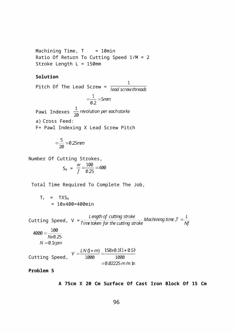
System Are:
Complete Absence Of Defects In Surface Layer.A Very Thin Layer (5 To 20 Microns) Is Removed,Method May Be Used For Internal And External Surfacing Of Parts Made Of C.I., Steel, And Non-Ferrous Alloys.A Fine Grit (Grain Size 400-600) Abrasive Strata Is Retained In A Suitable Holder And Applied To The Work Piece With A Light Spring Pressure.Low Work Rotational Speed (2 To 20 Mpm).The Work Piece Is Reciprocated To Me Requirement Of The Shape Being Surfaced.Longitudinal Feed Ranges From 100 To 150 Micron Per Work Piece Per Revolution.Abrasive Stick Oscillates Rapidly In Short Strokes (2 To 5mm) With A Frequency Of 500-1800 Strokes Per Minute.Spring Holds The Stick Against Work With A Force Of 20 To 100 N.
Special Lubricant (Mixture Of Kero And Oil) Is Used To Get High Quality Finish.Special General Purpose Machine Tools Are Available For Super Finishing. Ordinary Machines Like Lathes Are Also Sometimes Employed. Single Purpose Machine Tools For Finishing Crankshaft Journal And Crankshaft Are Also Sometimes Used.It Would Be Noticed That In Many Respects ‘Honing’ And Super Finishing Have Certain Common Features And Certain Differences. These Have Been Brought Out Is Table.
Table: Honing And Super Finishing Relative Comparison
Sl.No
Point Of Comparison
Honing Super Finishing
1. Creating Dimensions
Possible Not Possible
2. Motions Two Many Paty Of An Abrasive Grain Is Never Repeated
3. Employment Mostly For Internal Surface
Largely For One Side Surface.
4. Operating Speed Higher Lower.5. Pressure On Work Higher Too Low. Even Very
Fine Delicate Parts Can Be Super Finished.
6. Length Of Stroke Longer Low 1.5 M To 6 M.
96

Figure: Shaft For Super Finishing
Polishing
It Is A Surface Finishing Operations Which Is Employed For Removing Scratches, Tool Marks And Similar Other Irregularities From The Job Surfaces Produced Through Other Operations, Like Machining, Casting Or Forging. The Primary Object Of This Operation Is Only To Improve Surface Finish And It Is, Therefore, Employed Only Where Dimensional Accuracy Is Not To Be Closely Controlled.
This Operation Is Performed By Means Of Abrasive Coated Wheels Or Belts. The Wheels Used Are Disc Shaped And Termed As Bobs And Mops. The Former Is Made Of Leather, Felt Or Wood, To The Periphery Of Which Are Coated The Abrasive Particles With The Help Of Glue. These Wheels Operate At A Speed Of 1200 To 1500 Meters Per Minute (Linear) And Are The First To Be Used In The Operation. They Are Followed By The Other Type Of Wheels, Called Mops, Which Normally Operate Between 1000 To 1500 Meters Per Minute. They Are Made Of Cloth, Or Leather. Both Natural And Artificial Abrasive Grains Are Used For Coating These Wheels, But In Either Case They Should Be Of A Very Fine Grit. This Operation May Be Done By Hand Or Machines. In Some Cases, Where Only A Few Pieces Are To Be Polished, The Polishing Wheel Can Be Attached To Me Spindle Of A Pedestal Grinder In Place Of Toe Regular Grinding Wheel, And The Operation Performed By Feeding The Work Against It By Hand. For Production Work, Specially Designed Semi-Automatic And Automatic Polishing Machines Are Available.Buffing
97

It Is Also A Surface Finishing Operation Which Is Usually Performed After Polishing To Provide A High Luster To The Polished Surface. Obviously, There Is No Appreciable Amount Of Stock Removal From The Work Surface. Wheels Used In Buffing Are Made Of Linen, Cotton Cloth, Wool Of Felt, Which Are Charged With Loose Abrasive Grains Almost In The Same Way As A Lap. Buffing Belts Are Also Made In The Same Way As Wheels. A Very Fine Abrasive Is Used For Being Charges To These Wheels Or Belts. Charging Is Usually Done By Means Of Sticks Made Of Abrasive And Wax. Frequent Recharging Is Normally Needed During The Operation.
Buffing Compounds
Buffs Are Designed To Carry An Abrasive Compound That Is Either Sprayed On In Liquid Form Or Is Automatically Applied In Stick Form. Liquid Applications Generally Offer Better Control Of Delivery And, When Employed Properly, Guarantee That An Acceptable Level Of Compound Is Maintained On The Buff Wheel.
Typical Compounds Contain A Number Of Abrasives Such As Aluminum Oxide, Calcined Alumina, Red Rouge Iron Oxides, Green Chrome Oxides, Tripoli And Pumice. Compounds Are Formulated For A Specific Task; Some Are Designed For Heavy Stock Removal And Others To Achieve More Reflective Surfaces.
Tumbling
Jobs Are Tumbled In A Rotating Barrel Containing Abrasive Particles, Saw Dust, Stones And Sand Along With Water Or Some Chemicals. The Process Is Used To Remove Burrs Or Scale From Castings, Forgings And Screws Etc.
Burnishing
It Is A Process Of Polishing Without The Use Of Abrasive Particles. Solid Tungsten Carbide Rollers Are Pressed Against The Rotting Job And Thus A Fine Finish Is Obtained By The Rubbing Action Of Rollers On The Work Piece Surface. The Process Is Used For Finishing Bronze Sleeves, White Metal Hearings And Railway Axis.
The Different Types Of Sawing Machines
TYPES OF SAWING MACHINE
98
1. Reciprocating Saw(A) Horizontal Saw (B) Vertical Saw
2. Circular Saw(A) Cold Saw (B) Steel Friction Disk(C) Abrasive Disk
3. Band Saw
(A) Contour Band Saw (B) Friction Blade.
RECIPROCATING SAW
The Reciprocating Saw Is Usually Called Power Hack Saw. This Machine May Be Crank Driven Or Hydraulic Driven. The Blade Is Reciprocated On The Work Piece. During The Cutting Stroke, The Blade Is Forced Into The Work. It Is Lifted Up During Idle Strokes. A Line Diagram Of A Crank Driven Power Hack Saw Is Shown In The Figure. A Motor Drives The Crank. The Crank Gives Reciprocating Motion To The Frame. The Frame Slides In A Guide Way Of The Over Arm. The Over Arm Is Hinged To The Machine.
The Frame Is Fitted With A Straight Blade. The Machine Has A Quick Action Vice. It Can Be Adjusted At Weight Provided On The Frame. It Is Called The Gravity Feed. During The Idle Stroke The Frame Is Lifted Up By The Crank Mechanism. It Is To Make The Blade Clear Off The Work. A Whit Worth Mechanism Is Provided For The Quick Return Of Blade. A Cam Fitted To The Main Shaft Carries A Cut Off Switch. It Cuts Off The Motor At The End Of A Cut. Coolant Provision Is Made For Efficient Operation And Longer Life Of The Blade.
Figure: Reciprocating Saw
99

CIRCULAR SAW
The Machines Using Circular Saw Are Commonly Called Cold Sawing Machines.
Figure: Circular Cold Saw Machine
A Line Diagram Of Hydraulic Feed Circular Cold Saw Is Shown In The Figure. The Box Shaped Base Of This Machine Houses The Various Mechanism (Chip Remover, Hydraulic Mechanism And Coolant Pump Etc). The Blade Carriage Moves To And To And Fro On The Horizontal Guide Ways. The Guide Ways Are Provided Or, The Top Of The Base.
Vice Or Hydraulic Clamping Mechanism Is Provided To Clamp The Work In Position. The Lifting And Advancing Work Is Also Done By Hydraulic Means. An Electrical Motor Is Provided To Drive The Saw Blade Spindle Through ‘V’ Belt, Worm And Worm Wheel And Speed Gear Box.
The Blade Carriage Feed Is Operated Hydraulically. The Machine Has A Wide Range Of Cutting Speed, Ranging From 6 Mpm. The Saw Blades Are Made Solid Or With Segmental, Teeth Or Inserted Teeth. The Blades Cut Very Rapidly Because Of Large Diameter, But It Runs At Relatively Slow Speed. The Cut Is Made Very Smooth And Accurate.
BAND SAW
Introduction
In Band Saw, The Metal Is Cut By A Band. The Band Is An Endless Blade. Band Saw May Be Vertical Or Horizontal Type. In Vertical Type
100
The Work Is Supported On A Horizontal Table. The Saw Runs In Vertical Position. In Horizontal Type, The Work Is Held In Vice, A Small Band Saw Operates Above The Work Nearly In A Horizontal Position.
Vertical Band Saw
A Vertical Band Saw Is Shown In Figure. The Bed Is A Box Type Hollow Casting. It Is Cast Integral With The Vertical Column. The Lower Wheel Is Fitted Inside The Bed. The Table Has A Long Slot At Its Centre. The Saw Blade Passes Through It.
The Box Type Vertical Column, Houses A Coolant Pump Vertical Column And The Electric Motor. The Top Portion Of Column Is Extended Out. It Is Support The Upper Wheel. It Is Also Fitted With A Cover To Open Or Close. The Upper Wheel And The Lower Wheel Are Connected By Means Of The Endless Saw Blade. The Centre Distance The Two Wheels Can Be Adjusted, By Raising Or Lowering The Upper Wheel. It Is To Adjust The Tension In The Blade. The Blade Is Kept Straight By Means Of Guide Wheels When It Penetrates Into Work.
Figure: Vertical Band Saw
Horizontal Band Saws
This Type Of Machine Is Also Known As A Cut-Off Band Saw Or Cut-Off Band Machine. In General Appearance They Look Like A Power Hacksaw, But The Cutting Mechanism Of These Saws Is Quite Different. The Frame Of These Machines Carries Two Wheels, With Their Axes Horizontal, Which Are Connected Together By Means Of An Endless Saw Band. A Tension Control Mechanisms Always Maintains Proper Tension In The Blade, So That It Runs Continuously When The Wheels Rotate.
101

One Of The Wheels Is The Driving Wheel, Connected To The Motor, While The Other Wheel (Driven Wheel) Acts As An Idler Wheel. There Are Two Guides Provided On The Path Of The Band. These Guides Turns The Blade Such That It Runs Vertical Between The Two Guides To Cut The Work Piece Vertical Cutting Of The Work Piece Due To Turned-Band By Guides Is Quite Clearly Visible. The Frame Of The Machine Is Normally Hinged So That It Can Be Swing In A Vertical Place To Raise It After Cutting Or Lower It Before Starting Sawing. A Hydraulic Or Pneumatic System Controls The Cutting Fluid Supply And Many Other Mechanisms Of The Machine.
The Adjustable Supports And Guides Incorporated At The Cutting Area Support The Band To Enable It To Bear The Applied Cutting Force And Turn It To Become Vertical To Saw The Work Piece In A Vertical Plane, As Shown In The Diagram. Cutting Takes Place Due 10 Continuous Feeding Of The Band Into The Work, Since The Saw Band Continuous To Run In The Same Direction Always. These Machines Always Operate At Higher Cutting Speeds Than Those Used For Reciprocating Power Hacksaws. A Few Important Points To Be Borne In Mind While Operating These Machines Are:
Band Tension Should Be Correctly Adjusted. Wheel Guards Should Be Locked Before Starting Sawing. Proper Saw Blade, Speed And Feed Should Be Used. Proper Coolant, If Required, Should Be Used And In Abundance. The Band Supports And Guides Should Be Adjusted As Close To
The Work Piece As Possible. The Work Piece(S) Should Be Tightly Clamped.
Figure: Principle Of Operation Of A Horizontal Bandsaw Machine
FRICTION SAW
102

Friction Sawing Machine Has A Disk. The Disk Is Nothing But A Circular Blade. It Has Almost No Teeth. When The Disk Is Rotating At A Speed (About 6000 Mpm To 800 Mpm) Heat Is Produced Due To Friction. It Quickly Melts The Work Piece In Contact With The Disk. Now The Tensile Strength Of The Steel Is Lowered As The Temperature Increases. The Heated Metal Is Finally Weakened And Removed By The Disk. Friction Sawing Is A Fast Cutting Operations With Less Accuracy. It Is Not Limited By The Hardness Of The Material. It Can Easily Cut Stainless Steel And High Carbon Steel. Non Ferrous Metals Cannot Be Cut Satisfactorily In The Saw.
ABRASIVE CUT-OFF MACHINE
This Machine Has A Box Type Base. The Top Of The Base Is Used As Table. A Vise Is Fitted On The Top Of Table. There Is A Swing Type Frame. It Is Pivoted To The Body Of The Machine. A Motor Is Fixed At The Hack End Of The Frame. An Abrasive Circular Saw Is Fitted To The Front End Of The Frame. The Abrasive Circular Saw Is Nothing But A Blade Of This Grinding Wheel. The Wheel Gets Power From The Motor Through ‘V’ Belt. The Wheel Rotates At High Speed. Abrasive Wheel Is Fed Through Work, By Pressing The Handle Manually.
Figure: Abrasive Cut Off Machine.
Different Gear Generation Processes.
GEAR GENERATION PROCESS
Introduction
103

In Cutting Gears By Using A Generating Type Of Machine, The Gear Teeth Are Formed As A Result Of Certain Relative Motions Between Gear Blank And Cutter, Instead Of Simply Reproducing The Shape Of A Formed Cutter. A Generating Process Is Capable Of Enabling A Cutter Of Given Pitch To Cut Gears Having Different Numbers Of Teeth To The Correct Shape.
Gear Shaping
Shaper Cutter Generating Process: This Process Is Based On The Fact That Any Two Involutes Gears Of Same Pitch Will Mesh Together. In The Shaper Cutter Generating Process, The Cutter Is Given A Reciprocating Motion, As In A Shaper. It Will Be Capable Of Cutting A Gear Blank And Generates Gear Teeth. A Gear Shaper Cutter Is Shown In The Figure (A).
Figure (A) Gear Shaper Cutter. The Figure (B) Shows The Setup And Operation Of A Gear Shaper
Cutter.
104

Figure (B) Set Up Of Shaper Cutter Gear Generating Process
In The Operation, Both The Cutter And The Flank Rotate At The Same Pitch Line Velocity And In Addition, A Reciprocating Motion Is Given To The Cutter. The Rotary Feed Mechanism Is So Arranged That The Cutter Can Be Automatically Fed To The Desired Depth While Both Cutter And Work Are Rotating. The Cutter Feed Takes Place At The End Of The Stroke At Which Time The Work Is Withdrawn From The Cutter By Cam Action. The Usual Practice Is To Have The Cut To Take Place On The Down Stroke. Although In Some Cases The Cutting Action Is Of Necessity On The Up Stroke. The Cutter Gear Method Of Generating Gears Is Not Limited To Involute Spur Gears, But Has Many Other Applications. By Using A Spiral Cutter And Giving It A Twisting Motion On The Cutting Stroke Spiral (Or) Helical Gears May Be Generated. Worm Threads May Be Cut In A Similar Fashion.
Applications: Gears Produced By Gears Shaper Find Application In Automobiles, Machine Tools, Instruments, Machinery, Clock And Other Equipment.
Pinion Cutter Generating Process:
The Pinion Cutter Generating Process Illustrated In Figures (A) And (B) Is Fundamentally Same As The Rack Cutter Process And Instead Of Using A Rack Cotter It Uses A Pinion To Generate The Tooth Profile. The Cutting Cycle Is Commenced After The Cutter Is Fed Rapidly Into The Gear Blank Equal To The Depth Of Tooth Required. The Cutter Is Then Given Reciprocating Cutting Motion Parallel To Its Axis Similar To The Rack Cutter And Blank Are Made To Rotate Slowly About Their Axis At Speeds Which Are Equal At The Mating Pitch Surfaces. The Rolling Movement Between The Shaping Machines May Be Reciprocated Either In The Vertical Or In The Horizontal Axis. The Following Are The Advantages Of Pinion Cutter Generating Process.
105
Figure: Pinion Cutter Generating Process
A Single Cutter Can Be Used For Cutting All Spur Gears Of Identical Pitch As That Of The Cutter.
Internal Gears Can Be Generated By Pinion Cutter Generating Process.
The Rate Of Production Of Gears Is Higher, Because The Cutting Is Continuous.
The Mechanism Of The Machine Is Simple Than Rack Cutter Process.
Gear Planning (Rack Cutter Generating Process)
The Rack Cutter Generating Process Is Also “Gear Shaping Process”. In This Method, Illustrated In Figure The Generating Cutter Has The Form Of A Base Rack For The Gear To Be Generated. The Cutting Action Is Similar To The Action Of Shaping Machine. The Cutter Reciprocates Rapidly And Removes Metal Only During The Cutting Stroke. The Blank Is Rotated Slowly But Uniformly About Its Own Axis, And Between Each Cutting Stroke Of The Cutter, The Cutter Advances Along Its Length At A Speed Equal To The Rolling Speed Of The Cutter, The Cutter Advances Along Its Length At A Speed Equal To The Rolling Speed Of The Mating Pitch Lines. When The Cutter And Blank Have Rolled A Distance Equal To One Pitch Of The Blank, The Motion Of The Blank Is Arrested, The Cutter Is Withdrawn From The Blank To Give Relief To The Cutting Edges And The Cutter Is Returned To Its Starting Position. The Blank Is Next Indexed And The Next Cut Is Started Following The Same Procedure. The Helical Gears Are Cut By Swiveling. The Cutter Slide To The Required Helix Angle. The Cutter Now Reciprocates In A Path Set By The Helix Angle While The Rotary Movement Of The Blanks Is Continued. The Following Are The
106

Advantages Of Rack Cutter Generating Process.
Figure: Rack Cutter Geno-Rating Process
A Single Cutter Of Any Give Pitch Can Cut Gears Of Any Number Of Teeth Having The Same Pitch.
The Tooth Profile Generated Is Most Accurate Than Any Other Method.
The Rate Of Production Is Higher Than That Of The Formed Cutter Method.
Gear Hobbing
Hobbing Is A Process Of Generating A Gear By Means Of A Rotating Cutter Called Hob. The Hob Has Helical Threads. Grooves Are Cut In The Threads Parallel To The Axis. This Will Provide The Cutting Edges. Proper Rake And Clearance Angles Are Ground On These Cutting Edges. The Rotating Hob Acts Like A Continuously Moving Rack As It Cuts.
Figure: Gear Hobbing
The Gear Blank Is Mounted On A Vertical Arbor. The Hob Is Mounted In A Rotating Arbor. The Hob Axis Is Tilted Through The Hob Lead Angle A So That Its Teeth Are Parallel At The Axis Of The Gear Blank.
Then = (90 - 1)
107

Where 1 = Helix Angle Of The Hob Thread
The Hob Axis Is Inclined At With The Horizontal As Shown In The Figure.
Figure:Note: (Hob Lead Angle - 90 - Hob Helix Angle)
The Hob Is Related At Suitable Cutting Speed. It Is Fed Across The Blank Face. The Hob And Blank Are Made To Rotate In Correct Relationship To Each Other I.E., They Rotate Like A Worm And Worm Gear In Mesh. For One Rotation Of The Hob, The Blank Rotates By One Tooth, (In Case Of Single Start Hob). Figure.
For Cutting Helical Gears, The Axis Of The Hob Is Inclined To Horizontal By A Where.
= + (90 - 1) (If The Helix Of The Hob And The Helix Of The Gear To Be Cut Are Different (I.E.) One Is Right Handed And Another Is Left Handed.)
= - (90 - 1) (If The Helix Of The Hob And The Helix Of The Gear To Be Cut Are Both Right Handed Or Both Is Left Handed.)
Where, = Helix Angle Of The Helical Gear To Be Cut. = Helix Angle Of The Hob.
Application:
Hobbing Is Used For Generating Spur, Helical And Worm Gears.
Advantages
A Single Hob With The Given Module Can Be Used For Generating Gear With Any Number Of Teeth Of The Same Module.
108

The Same Hob Can Be Used For Spur And Helical Gears. Operations Is Continuous. So Very Fast Rate Of Production. Perfect Tooth Shape Is Obtained. Worm Gears Are Generated Only By Hobbing. Process Is Automatic And So Less Skived Operator Is Sufficient. Multiple Blanks Can Be Cut At A Time. Hence High Rate Of
Production.
Limitations:
Internal Gears Cannot Be Generated. Hobbing Cannot Be Used For Producing Gear Teeth Very Near To
Shoulders.Bevel Gear Generator
There Are Two Types Of Bevel Gear Generators. They Are;
Straight Bevel Gear Generator. Spiral Bevel Gear Generator.
Straight Bevel Gear Generator
The Generating Process Is Similar To Rolling Of A Bevel Gear Blank Of An Imaginary Crown Wheel. The Crown Wheel Is A Bevel Gear Having Pitch Cone Angle Of 180 (See Figure). The Teeth Of The Crown Wheel Are Straight And Radial. In Practice, Instead Of All Crown Wheel Only Two Teeth Are Used For Generation Of A Bevel Gear From A Blank. Two Cutting Tools In The Form Of Two Teeth Of A Crown Wheel Are Used. The Tools Have The Profile Of Teeth Being Cut. The Two Tools Together Cut Only One Tooth Space At A Time.
Figure:
The Machine Is Shown In Figure. The Gear Blank Is Held In An Arbor. The Axis Of Blank Is Inclined At An Angle With The Horizontal. The Angle Is 90 - Pitch Cone Angle). The Blank Is Given A Rolling
109

Motion About Its Axis. Two Straight Cutting Tools Are Held In Reciprocating Sides. These Tool Slides Reciprocate Along The Guide Ways On The Face Of A Cradle. The Cradle Rolls In Relation To The Gear Blank. The Two Cutting Tools Reciprocate Across The Face Of The Gear Blank. They Take Series Of Cuts On The Blank. By The Rolling Action Of The Blank And The Cradle, The Tools Generate The Required Teeth On The Blank.
The Process Of Bevel Gear Generation Is Shown In Figure.
Figure:
At The Tool Position 2, One Of The Tool Starts Cutting The Gear Blank. In The Position 3 And 4, Both The Tools Take The Cut. Now One Complete Tooth Space Is Generated. Now The Cradle And Gear Blank Roll In The Reverse Direction (Position 5). The Tools Also Slide Upwards. At Position 6, The Tools Get Relieved Of The Blank. The Blank Is Automatically Indexed For The Next Teeth. The Cycle Is Repeated.
Figure:
110

Application:
In This Method, The Straight Bevel Gears Are Generated In Large Numbers. This Process Can Also Be Used For Finishing Bevel Gears.
Short Notes On i) Gear Burnishingii) Gear Shavingiii) Gear Grindingiv) Gear Lapping.
Gear Burnishing
This Is A Method Of Finishing Of Gear Teeth Which Are Not Hardened. This Is A Cold Working Process. This Method Is Used To Improve The Surface Finish Of The Gear Teeth. This Also Increases The Hardness At The Teeth Surface. The Principle Of Working Of A Burnishing Process Is Shown In Figure. In Burnishing, The Gear To Be Finished (Called Work Gear) Is Rolled Between Three Burnishing Gears. The Teeth Of Burnishing Gears Are Very Hard, Smooth And Accurate.
Figure: Gear Burnishing
They Are Arranged At 120 Position Around The Work Gear. Power Drive Is Given To One Of The Burnishing Gears. The Other Two Gears Idlers. Burnishing Pressure Is Applied To The Idlers. The Gears Are Rotated In One Direction For Same Period. Then They Are Rotated In The Reverse Direction For The Same Period.
The Pressure Is Applied By The Herder Burnishing Teeth On The Work Gear. The Surface Hardness Of Teeth In The Work Gear Is Also Increased. The Teeth Are Finished On Both The Faces Uniformly. This Is Obtained By The Rotation Of The Gears In Both The Direction.
111

A Lubricant In Applied Between The Teeth To Get Smooth Surface Finish. This Also Reduces Friction And Heat.
Gear Shaving
This Is The Most Common Method Of Gear Finishing. In This Method, A Very Hard Gear Shaving Cutter Is Used To Remove Fine Chips From The Gear Teeth. The Shaving Cutter May Be In The Form Of A Rack Or A Pinion. The Rotary Method Using Pinion Cutter Is Used On All Types Of Gears. The Rotating Cutter Will Have Helical Teeth Of About 15 Helix Angle. The Cutter Has A Number Of Serrations On Its Periphery. These Act As Cutting Edges.
Gear Finishing For Hardened Gears
Gear Grinding
Gear Grinding Is Used For Finishing Gears After Hardening. Gear Grinding Is Done For,
Increasing The Accuracy Of Gears. Improving The Surface Finish. Removing The Distortion Due To Heat Treatment.
There Are Two Method Of Gear Grinding. They Are,
Formed Wheel Grinding Generation Gear Grinding
A) Formed Wheel Grinding:
Informed Wheel Grinding, The Grinding Wheel Is Dressed To The Form Of Tooth Space Of The Gear (Involute Profile). The Grinding Wheel Is Moved Parallel To The Work Gear Axis.
112
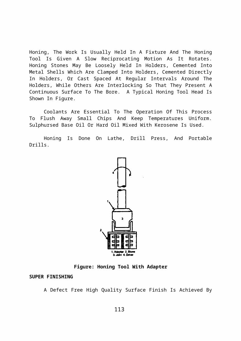
Figure: Formed Wheel Grinding
After Grinding One Tooth Space, The Work Gear Is Indexed To The Next Tooth Space. About Three Passes Are Required To Finish The Tooth Space. Proper Coolant Should Be Used While Finishing By Grinding.
B) Generation Gear Grinding
The Work Gear Is Rolled Along An Imaginary Rack. Rolling Is Done In Both The Directions To Grind Both Sides Of The Tooth. The Grinding Wheel Reciprocates Along The Length Of The Tooth. The Grinding Wheel Is Dressed In The Form Of Rack Teeth.
Figure: Generation Gear Grinding
The Work Gear Rotates About Its Axis. The Gear Is Also Given A Linear Motion Along Its Axis. The Linear Motion And Rotary Motion Are Opposite To Each Other. These Two Motions Together Give A
113

Generating Motion.
Figure: Generation Gear Grinding
Bevel Gears Are Also Ground By End Type Grinding Wheel As Shown In Figure.
Gear Lapping
The Hardened Gears Are Finished Accurately By Lapping Process. Lapping Removes Very Small Amount Of Metal (Not More Than 0.05 Mm).
A Lapping Arrangement Is Shown In Figure. The Work Gear Is Rolled Between Three Lapping Gears. The Lapping Gears Are Made Of Cast Iron. The Lapping Gears Are Arranged At 120 Position Around The Work Gear.
Figure: Gear Lapping
114
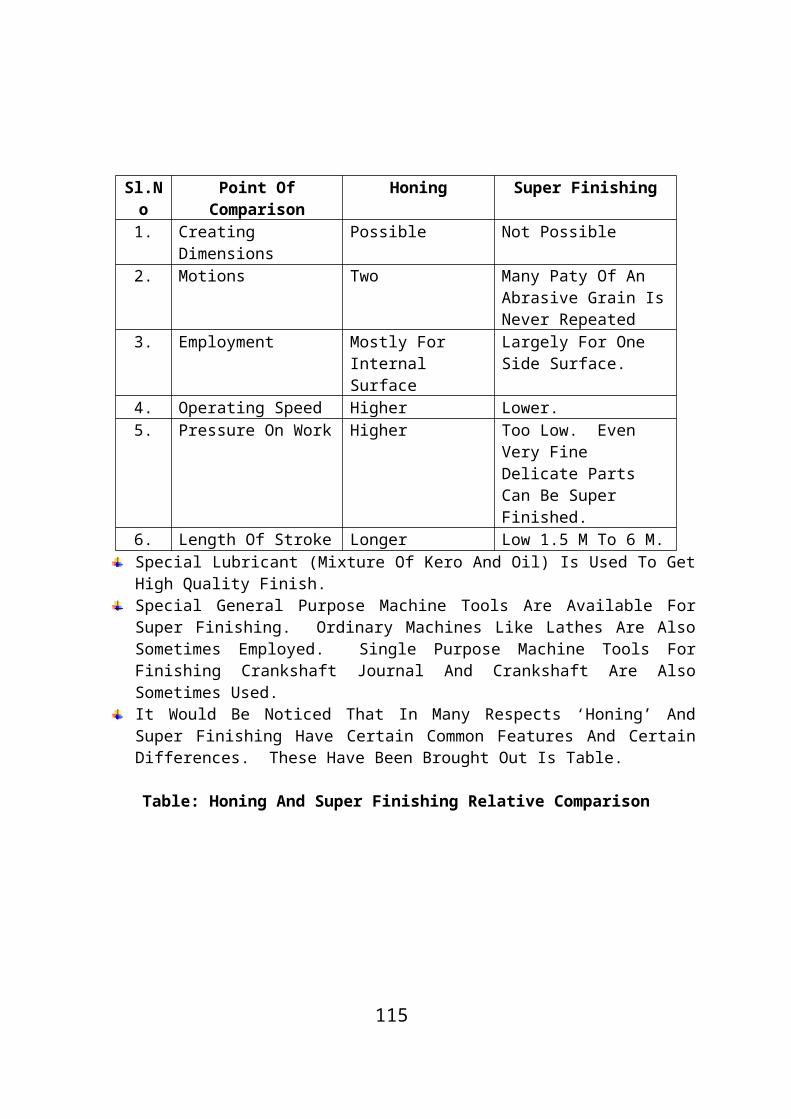
The Axis Of The Two Lapping Gears (2 And 3) Is Inclined At About 4 To The Work Gear Axis. The Axis Of The Other Lapping Gear (1) Is Parallel To The Work Gear Axis. The Drive Is Given Through This Gear. When Gears Rotate, A Lapping Compound Is Applied Between Them. The Compound Is A Mixture Of A Very Fine Abrasive Powder And Kerosene. The Lapping Process Improves The Tooth Contact
UNIT – V
CNC MACHINE TOOLS AND PART PROGRAMMING
PART – A
The Components Of NC Machine Tool.
Machine Control Unit NC Program Servo Mechanism Machine Tool. Manual Control
NC Program
NC Program Is An Instruction Set In The Form Of Numerals, Alphabets And Symbols.
Incremental System
In This System The Tool Position Or Locations Are Indicated With Reference To A Previously Known Location.
The Advantages Of CNC.
115

Editing The Tape Unit Conversion High Productivity
Manual Part Programming
In Manual Programming The Programming Instruction Are Laid Down On A Manuscript. Manuscripts Come In Various Forms Depending On The Capability Of The Machine Tool.
Some Motion Statements In APT.
GOUP, GO DOWN, GOFWD, GOBACK, GORUT, GOLFT Are The Motion In APT.
Tool Reference
It Is The Point Of Rotation Of The Tool Post. It Is Useful For Cutter Tool Compensation, Tool Changing Etc.
Cutter Compensation
When Part Program Are Prepared For A Particular Cutter Diameter The Variations Is The Actual Cutter Diameter If Any In Given As Cutter Compensation.
PART – B
The Procedure For Developing Manual Part Programming.
Procedure For Developing Manual Part Programme
The Part Programming Requires An NC Programmer To Consider Some Fundamental Elements Before The Actual Programming Steps Of A Part Takes Place. The Elements To Be Considered Are As Follows:
Type Of Dimensioning System Axis Designation NC Words Standard G And Codes Machine Tool Zero Point Setting.
Type Of Dimensioning
116

After Deciding What NC Machine Is Best Suitable And Available For The Application, We Determine What Type Of Dimensioning System The Machine Uses I.E., Whether An Absolute Or Incremental Dimensional System.
Axis Designation:
Another Consideration Is Designation Of The Axes Of The Machine Tool. In Most Cases The Programmer Already Knows This Fundamental Element When He Selects The NC Machine Tool For His Job. The Most Important Factor In Axis Designation Is The Location And Position Of The Spindle.
The Part Programmer Also Determines How Many Axes Are Available On Machine Tool I.E., X, Y,Z, A, B, Or C And So On And Also Whether Machine Tool Has A Continuous Path And Point To Point Control System.
NC Words
In Order To Understand The Language Of NC Information Processing The Following Definition Should Be Understood:
A ‘Bit’ Is The Basic Unit Of Information Represented By Either The Absence Or The Presence Of A Hole Punched On The Tape. Bit Is An Abbreviation Of “Binary Digit”, Which Can Be ‘0’ Or ‘1’.
A Code Or Character Is The Series Of Combination Of ‘1’s And ‘0’s. It Represents A Number Or An Alphabet Or Any Symbol. One Character Is Punched In A Single Row On The Tape E.G. Number ‘9’ Is Represented By 1001. Certain Codes Or Characters Known As “Redundant Codes” Are Necessary To Reduce The Possibility Of Incorrect Reading Of Tape By The Tape Reader. It Is An Information Contained In The Data Which Is Not Essential But Is Added To Increase Readability (E.G. A Code Known As “End Of Block” Or Simply ‘EOB’ Used To Separate Each Block Of Data Irrespective Of Its Length).
An NC Word Is A Unit Of Information, Such As A Dimension (E.G. X01000 Or Y10025) Or Feed Rate (E.G. F200) And So On.
117

A Block Is A Collection Of Complete Group Of NC Words Representing A Single NC Instruction (E.G. N1 G01X100 Z100 F100). An End Of Block (EOB) Symbol Is Used To Separate The Blocks And End Of Block (EOB) Is A Hole Punched In 8th Columns Of The Tape. Various NC Words That Are Mostly Used Are As Follows:
1. Block Number/Sequence Number (N Words):
Each Block Of The Program Has A Sequence Number Which Is Used To Identify The Sequence Of Data In It Which Is In Ascending Numerical Order. When The Part Program Is Read From The Tape, Each Sequence Number Is Displayed On The Panel Of NC Machine Tool, As Long As That Block Commands Are Performed. This Enables The Operator To Know Which Sequence Of Block Is Being Performed Practically By The Tool. It Consist Of Character ‘N’ Followed By A Three Digit Number Raising From ‘0’ To ‘999’.
2. Preparatory Functions (G-Words :
The Preparatory Function Is Used To Initiate The Control Commands, Typically Involving A Cutter Motion I.E. It Prepares The MCU To Be Ready To Perform A Specific Operation And Interpret, The Data Which Follows The Way Of This Function. It Is Represented By The Character ‘G’ Followed By Two Digit Number I.E. ’00 To 99’. These Codes Are Explained And Listed Separately.
3. Dimension Words (X, Y & Z Words):
These Dimension Words Are Also Known As ‘Co-Ordinates. Which Gives The Position Of The Tool Motion. These Words Can Be Of Two Types:
(A) Linear Dimension Words
X, Y, Z For Primary Or Main Motion U, V, W For Secondary Motion Parallel To X, Y, Z Axes Respectively P, Q, R For Another Third Type Motion Parallel To X, Y, Z Axes
Respectively
(B) Angular Dimension Words
A, B, C, For Angular Motion Around X, Y, Z Axes Respectively. I, J, K In Case Of Thread Cutting Is For Position Of Arc Center,
Thread Lead Parallel To X, Y, Z Axes.
118

These Words Are Represented By An Alphabet Representing The Axes Followed By Five Or Six Digits Depending Upon The Input Resolution Given. The Following Points May Be Noted While Calculating The Number:
Decimal Point Should Not Be Allowed E.G. X = 5.325 Will Be Represented As X5325 In A Five Digits System I.E. The Last Three Digits Are Used For The Decimal Part Of The Number. Some Machine Allow Omission Of Leading Zeros, Hence The Same Can Be Represented As X5325.
It Absolute System, All Dimension Should Be Expressed In Mm.
All Angular Dimensions Should Be Expressed As A Decimal Fraction Of A Revolution.
In Absolute System, All Dimensions Should Be Positive.
In Incremental System The ‘+’, ‘-‘ Sign Represent The Direction Of Motion.
4. Feed Rate Word (F-Word):
It Is Used To Program The Proper Rate, To Be Given In Mm/Min Or Mm/Rev As Determined By The Prior ‘G’ Code Selection G94 And G95 Respectively. This Word Is Applicable To Straight Line Or Contouring Machines, Because In PTP System A Constant Feed Rate Is Used In Moving From Point To Point.
It Is Represented By ‘F’ Followed By Three Digit Number E.G. F100 Represents A Feed Rate Of 100 Mm/Min.
5. Spindle Speed/Cutting Speed Word (S-Word):
It Specifies The Cutting Speed Of The Process Or The Rpm Of Spindle. It Is Also Represented By ‘S’ Followed By The Three Digit Number. If The Speed Is Given In Meter Per Min, Then The Speed Is Converted In Rpm Of Spindle (E.G: S900 Represent 900 Rpm Of Spindle).
6. Tool Selection Word (T-Word):
It Consists Of ‘T’ Followed By Maximum Five Digits In The Coded Number. Different Numbers Are Used For Each Cutting Tools. When The T Number Is Read From The Tape, The Appropriate Tool Is Automatically Selected By ATC (Automatic Tool Changer). Hence This
119

Word Is Used Only For Machines With ATC Or Programmable Tool Turret. E.G. T01, T02, T03……. Represents The Tool Selection Word. Also Sometimes T-Word Is Used For Representing Offset Number Corresponding To X, Y, And Z Directions. With The Help Of Two Additional Digits, Given After A Decimal Point.
7. Miscellaneous Word (M-Words):
It Consists Of Character M Followed By Two Digit Number Representing An Auxillary Function Such As Turning ON/OFF Spindle, Coolant ON/OFF Or Rewinding The Tape. These Functions Do Not Relate Two Dimensional Movement Of The Machine.
8. End Of Block (EOB):
It Identifies The End Of Instruction Block.
The Constructional Detail Of CNC.
Constructional Details Of CNC
A CNC Should Be Of “Robust Construction With Minimum Friction And Backlash Eliminated”. The Design Consideration Of CNC Involves Stress Upon Two Areas:
Control System DesignMechanical System Design.
Control System Design
NC Machine Tool In The Past Had Been Very Unreliable. From A User Point Of View, It Was Very Difficult To Believe, That What Happed To A Machine, Which Had Given A Very Good Service For Years And Finally Lost Its Hand Wheels After Marrying To An NC Controller. Obviously, The Controller Unit Also Lacked The Reliability And Also The Proper Coordination Between Different Circuitry Element Or Parts. The User Is Confused Whether Between Relays, Transistors Or IC’s What Is Reliable. Hence, For The Selection Of Control System, There Are Four Main Considerations:
1. Analog Versus Digital
There Are Very Few Systems Which Are Either Completely Analog
120

Or Completely Digital. The Feedback Provided In The System Is Generally Of Analog Form And Converts The Data In Digital Form. Hence, Without Getting Into The Arguments Of Usefulness Of Both Systems, Care Should Be Taken For Selecting The Technology For Different Units Of Control Unit.
2. Punched Tape Vs. Mag Tape
It Is Not Feasible To Use A System With Magnetic Tape As The Input For Systems Of Simple Nature Such As Point To Point Applications Or Straight Lines Because Programming And Preparing Punched Tapes Is Cheap And Easy. Even Modifications Can Be Done Easily By Cutting A Part Or Simply Closing Holes Etc.
Wherease, In Case Of Magnetic Tapes A Large Volume Of Data E.G. Complex Contouring Parts Can Be Handled By It. Sometimes Magnetic Tapes Have More Detailed Cutter Path Information And Hence Eliminate The Used Of An Interpolator But Need An Extra Off-Line Computer For Calculation Purposes. So, The Choice Between Punched Tape And Magnetic Tape Depends Upon The Requirement Stability.
3. Open Loop Vs. Closed Loop Systems
As Already Explained Before, Open-Loop CNC System Have No Feedback Whereas Closed Loop Systems Make Use Of Feedback Transducers.
Although Closed-Loop Systems Seem To Be More Precise As Compared To Open Loop Systems, But They Are Comparatively More Expensive Than O.L.S. Moreover, Use Of Very Sophisticated “Digital Pulse Hydraulic Motor” Has Eliminated The Need Of Closed Loop Systems.
4. Linear Vs. Rotary Transducers
The Difference Between The Two, Is That Linear Transducers Get Direct Drive From Actual Slide Displacement, Whereas Rotary Transducers Have Indirect Measurement By Attachment To The Ends Of Lead Screws And Hence Only Simulates The Relative Movement Of Tool And Work Piece.
Although Linear Transducer Such As Ferranti Systems Have Found To Be More Accurate And Widely Accepted, But Slowly The Rotary Transducers Such As Synchro Are Also Getting Accepted.
To Each Of The Above Factors There Are Certain Framed Rules
121

Which Are Proven Ones. Hence, Until And Unless We Get A Feedback From Electronic Advisors, We Should Only Follow The Manufacture Of Repute.
Mechanical System Design
It Was Also Felt At A Later Stage That The Designs Of Conventional Machines Often:
Lack The Stiffness, Which Is Very Necessary For CNC Machines. Have Backlash I.E. Clearances In Threads Of Leadscrews Etc.
Which Are Almost Eliminated In CNC. Have Characteristic Of ‘Stick-Slip’ Which Appear To Be Very
Difficult To Be Controlled By CNC. Have Machine Tool Resonance And Have Machine Tool Chatter
Which Is Taken Care Of By :Chatter Compensation” In CNC’s.
All Of The Above Undesirable Characteristics Are Exhibited To A Less Or More Extent In All Of The CNC’s Due To The Economic Reasons. But A Careful Investigation All The Basic Mechanical Parts, Their Driving Mechanisms And Their Relative Motions Can Solve This Problem To A Greater Extent.
These Are Following Machine Elements Or Systems Which Are Considered At The Time Of Designing Of CNC Machines:
Main Structure Of CNC Machine Tool.Slide And Slide Ways.
Main Structure Of CNC Machine Tool
The Main Structure Of CNC Machine Tool Comprises Of A Bed, A Column Other Member, Such As Head Stock Of Lathe, Which Is Connected To The Bed.
The Basic Structure Of Machine Tool Transmits Cutting Force From Work-Piece To The Foundation. There Are Two Types Of Forces Which Act Upon:
Static Forces Inertia Forces
The Static Forces Are Exerted Commonly By The Weight Of Machine Tool Itself And Pressure Of The Cutting Tool On The Work
122
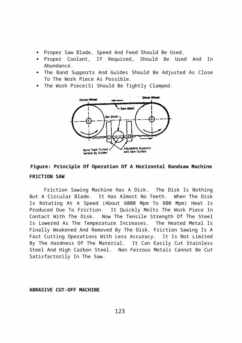
Piece. However, Gertia Forces Are Exerted By Rapid Acceleration And Deceleration. Both Of The Forces Tend To Bending Or Deforming The Table And This Way Head To Errors To The Tune Of 40 Mm. For A Manually Operated Machine Tool The Operator Can Correct The Error But In CNC Machines Control Tape Cannot Take Into The Forces Acting During The Machining Operation. The Bending And Deformation Can Also Be Caused Due To The Heat Effect In The Machine. The Heat Effect Can Put Tool In Out Of Alignment And Deform The Machine Bed And Table. The Other Cause For The Deformation Of Vertical Columns May Be The Mounting Of Driving Motors Directly On The Cutting Arm. The Various Steps Which Can Be Taken To Counter Cause Are:
a) Providing A Correctly Design Mild Steel Structure Having Stiffness.b) Use Of Ribs, Braces, Angle Plates To Increase The Stiffness Of
Machine Structure.c) Normal Weight Distribution Over The Entire Frame Of The
Machine.d) The Hollow Cross-Sections For Beds, Bases And Columns With A
Number Of Ribs Welded With The Walls Cater For The Rigidity As Well As Openings For Inspection, Lubrication And Collection Of Chips Coolants.
e) Thermo Symmetrical Design Of All Parts.f) Providing Large Heat Removing Surfaces.g) Use Of Excellent Coolants.h) Avoiding Direct As Well As Local Source Of Heat Such As Sun Light
And Electrical Motors/Oil Pumps Respectively.i) Reduction Of Ambient Temperature By Using Air-Conditioning
Units.j) Proper Alignment Of The Machine Elements Relative To Each
Other While In Operation As Well As In Stationary Conditions.
Figure: Thermal Sources Cause Of Inaccuracy In Machine Tools
Slide And Slideways
123

As We Know That The General Machine Tools Are Provided With Tables, Slides, Carriages Etc. To Carry The Work Pieces Or Cutting Tools Etc. These Parts Are Sliding Nature And Mounted On The Ways That Are Fixed On The Other Parts (Column, Housing, Bed Or Knee) Of The Machines Known As Sliding Ways.
These Slideways Should Be Rigid, Accurately Designed And Durable.
As The Requirement For Accuracy And Location Of Tables/Saddles Increases, More Attention Has To Be Given To The Frictional Resistance Of Slides. The Slip-Stick Motion Which Prevents Smooth Starting From The Rest Is Also Taken Care Of. To Overcome This Drawback Antifriction Bearing Arrangements Are Done To Substitute Sliding Friction With Rolling Friction. Different Methods To Achieve This Phenomenon Are As
1. Hydrostatic Type Slideways2. Anti Friction Type Slideways3. Wear Resistant Slideways.
1. Hydrostatic Type Slideways
The Slideways Of Many Machines And Particular Those With A Horizontal Bed Like Lathes, Exist Under Difficult Conditions For Cutting Forces Falling On The Sliding Surfaces. It Will Lead To Increase Friction And Wear Along With Loss Of Accuracy. Hence, A Constant Film Of Some Fluid Like Oil Or Air Prevents Metallic Contact Between The Sliding Members And Thus Reduces Wear To A Minimum.Hydrostatic Slideways Can Be Sub-Classified As:Oil Lubricated SlidewaysAir Bearing Slideways
(I) Oil Lubricated Slideways: Stress Is Made On Maintaining An Unbroken Oil Film. The Friction Is Minimizing By Forcing Oil Under Pressure Between The Mating Surface And The Pressure Is Automatically Varied. According To The Load On The Surface Resulting From The Weight Of Moving Member And Cutting Conditions. These Types Of Slideways Are Best Suitable For CNC Milling Machines.
124

Figure: Hydrostationally Lubricated Slideways.
The Oil Lubricated Hydrostatic Slideways Is Shown In Fig.
2. Anti-Friction Type Slideways
Conventional Slides, Having Sliding Friction Have A Highest Value Of Friction At Lowest Velocity. This Leads To A Jurky Action Due To Sticking Of Oil Lubricated Sliding Surfaces. To Avoid This Situation A Point Or Line Contact Is Made Instead Of Surface Between The Sliding Parts, There By Converting Sliding Friction Into Rolling Friction.
3. Wear Resistant Slideways
The Machine Tools Vary In Ability To Resist Wear And Tear Of Their Guideways. Machines, Such As Lathe And Planning Machine Operate Under Heavy Loads Where As Grinding Machines Have Very Less Wear And Tear On Their Slideways. For Economic Reasons, Cast Iron Is Used For The Body Of Both Types Of Machines. Hence, A Different Type Of Bearing Surface Is Applied. Method Use For This Purpose Is:
Flame Hardening Induction Hardening Fastening Hardening Surfaces Surface Coatings
Spindle
It Is The Expensive And Live Part Of The Machine Tool Which Gets The Power From Its Drive Unit And Delivers To The Work In Case Of Lathe Or To The Tool In Case Of Drilling Or Milling Machine. In Case Of Lathe Machine, It Also Holds The Work Piece. There Are Three Main Functions Of The Spindle As:
Centering The Job Or The Tool
125

Holding The Job Or The Tool Rotating The Job Or The Tool
So, On The Basis Of Above Functions, It Should Be Stiff And Short In Length To Get Increased Stability And Minimization Of Torsional Strain. It Should Be Very Close To The Front Bearing As Much As Possible To Maintain Stability And Smooth Operation.
The Centering Of The Spindle Is Made By Providing Either Internal Or External Tapers Or Cylinders. In Case Of Lathe Machine, The Spindle Consists Of A Centre, Taper Bore, Adapters (To Suit Centres Of Different Sizes And Tapers) And An External Cylinder To Locate Driving Chucks Plates As Shown In Fig. The Main Spindle Is Supported On High Precision Taper Roller Bearings To Provide High Rigidity, Thermal Stability And Consistent Production Accuracy.
Figure: Lathe Spindle
In Case Of Milling Machine, The Spindle And Internal Taper, Locates The Milling Heads Or Cutter Heads.
A Straight Fastening Passes Through The Full Lengths Of The Spindle As Shown In Fig.
Figure: Milling Machine Spindle
The Tenons (Projections) Are Secured To The Spindle Nose By Means Of Screws Which Transmits The Torque From The Spindle To The Arbor Or Milling Head.
126

Advantages And Disadvantages Of Using NC System.
Advantages And Disadvantages Of Using NC Machines
Some Prominent Advantages And Disadvantages Using NC Machines Are The Following:
Advantages:
1. Increased Productivity. Due To Reduced Setup And Lead Times.2. Reduced Scrap. Due To Elimination Of Human Errors And High
Accuracy Of NC Systems.3. Increased Rate Of Production. Due To Heavy Reduction In Non-
Machine Times And Optimization Of Machining Conditions.4. Reduced Nonproductive Time. Due To The Use Of Lesser Setups,
Lesser Setting Time, Lesser Work Handling Time, Facility Of Automatic Tool Changing On Some Machines, Etc.
5. Reducing Lead Time For Manufacturing. Due To The Requirement Of Fewer Setups And Less Setup Time.
6. Lesser Requirement Of Jigs And Fixtures. Due To The Fact That Work And Tool Positioning Is Done By NC Tape, Only Simple And Cheaper Varieties Of Fixtures May Be Needed In NC Machining.
7. Reducing Tooling Cost. Due To The Requirement Of Simpler And Less Fixtures, The Cost Incurred On The Design And Fabrication Of Fixtures Is Substantially Reduced.
8. Reducing Inspection Requirement. Due To The Production Of Parts Of Uniform Quality.
9. Higher Accuracy. The Degree Of Accuracy Of Parts Producing Through NC Machining Is So High And Quality So Uniform That There Is No Difficulty In Interchangeable Use Of These Parts.
10. Better Quality Control. Due To Higher Accuracy Of NC Systems, The Quality Of Products Is Effectively Controlled.
11. Ease Of Complex Machining. NC Facilitates Performing Of Complex Machining Operations Easily, Accurately And At Much Faster Rate.
12. Greater Flexibility In Manufacturing. Due To Easy Adaptability Of NC To Changes In Part Design, Changes In Production Schedule, Etc., According To Requirements.
13. Reduce Inventory. The Firm Can Do With A Smaller Inventory Due To Reduced Lead Times And Requirement Of Fewer Setups.
14. Greater Utilization Of Manpower. Since The Operator Is Not Required To Attend To A Running NC Machine Constantly, He Can
127

Be Utilized To Perform Some Other Functions During That Period.15. Reduction Of Human Error. Due To The Replacement Of All
The Operator’s Functions Of Conventional Machining By Tape In NC Machining, The Chances Of Human Errors Are Reduced To A Minimum.
16. Enhanced Safety Of Operator. The Operator’s Involvement In NC Operations Is Minimum Because The Console, Which Operates Different NC Systems, Is Located At A Distance From The Machining Area, The Operator Gets No Change To Be Exposed To This Area.
17. Better Safety Of Machine Tool. There Is Practically No Chance Of Any Damage To The Machining Tool Due To Human Error Since There Is Almost No Requirement Of Operator’s Involvement During The Operation.
18. Better Utilization Of Machine Tool. Due To Lesser Requirement Of Setup Time And No Requirement For Operator Adjustments And Manipulations More Time Is Available For Machining, Leading To A Greater Use Of Machining And, Thus, An Increased Rate Of Production.
19. Reduced Space Requirements. Lesser Storing Space Is Required In NC Machining, Because A Few Jigs And Futures Are Needed. Also, When A NC Machining Centre Is Used, It Eliminates The Requirement Of Many Conventional Machining Tools, Which Results In A Reduced Space Requirement For A NC Machining Shop.
20. Accurate Predictions. The Product Cost And Rate Of Production Can Be Accurately Predicted Because Of The Programmed Machining, Which Does Not Allow Any Deviation Of The Actual Production Time From The Programmed Time.
21. No Need Of Skilled Operator. Since All The Manual Skills Required In Conventional Machining Are Transferred To The Machine In NC, The Essential Requirement Of A Skilled Operator Can Be Easily Done Away With.
Disadvantages:
1. Heavy Investment. Which Should Be Justified By Full Utilization Of NC Machines, Otherwise The Invested Amount Will Be Blocked.
2. Costly And Complicated Maintenance. Because A Well Trained Maintenance Task Force Is Needed.
3. Need Of Well Trained And Highly Skilled Manpower. For Part Programming.
4. Surplus Labour. This Happens If NC Is Made Applicable To Existing Conventional Machine Tools. In That Case, A Fairly Large
128

Workforce Becomes Redundant And An Obvious Burden On The Organization.
5. Costly Control System.
The Different Components Of NC Machine Tool.
Components Of NC Machine Tool
The Main Components Of A NC Machine Tool Are:1. Machine Control Unit2. NC Program3. Servo Mechanism And Drive Unit4. Machine Tool5. Manual Control.
The Main Components Of The NC Machine Tool Are Shown In The Fig.1. Machine Control Unit (MCU)
It Is Also Called As Controller Unit. This Consists Of The Hardware And Electronics That Lead And Translate The Program Instructions Into Mechanical Actions Of The Machine Tool. The Main Elements Of The Machine Control Unit (MCU) Are A Tape Reader, A Data Storage Element (Data Buffer), Signal Output Channels To The Machine Tool And Signal Feedback Channels From The, Machine Tool.
Figure: Components Of Numerical Control
The Tape Reader Is An Electromechanical Device. The Purpose Of This Is To Read The Punched Tape Containing The Program Instructions.
2. NC Program
NC Program Is An Instruction Set In The Form Of Numerals, Alphabets And Symbols. These Instruction Sets Are Logically Organized To Carry Out A Set Of Specific Machining Operation To Produce A
129

Component Or “Part”. Hence It Is Called As A “Part Program”. The Part Programs Are Coded (Written) By A Part Programmer.
3. Servo Mechanism And Drive Unit
A Servo Mechanism Consists Of Elements Like Electric Motors, Gear Trains And Lead Screws. It Converts The NC Input Into Precision Mechanical Movements Of The Machine Tool Parts.
4. Machine Tool
Machine Tool Converts The Work Piece (Blank) Into A Finished Product.5. Operator Control/Manual Control
Figure: Configuration Of System-Computer Numerical Control
Operations Such As Motor Start-Stop, Change Of Speed, Change Of Feed, Coolant Supply, Etc Can Be Performed Manually Using This Control.
******************
130