Embed Size (px)
Citation preview
Pre-Engineering Graphics 2 Hinsdale Central High School

2 Pre-Engineering Graphics 2—Hinsdale Central High School
Pre-Engineering Graphics 2—Hinsdale Central High School 3
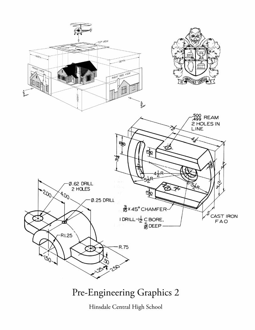
Pre-Engineering Graphics 2
Pre-Engineering Graphics 2 is the second course in a sequence in computer aided drafting at Hinsdale Central. This class will meet for one semester and upon completion of the course you will receive one half credit toward graduation. This course will cover several types of drafting.
At first, you will learn how to use the computer, as a tool to create the different kinds of drawings you will complete this semester. The software you will use is the latest version of AutoCAD. Each unit covered in class will serve as a “stepping stone” for the next unit. All work assigned is expected and required to be completed within the specified time period given to you by your teacher. Your drawing skill, neatness, accuracy and correct problem solution will determine the points you will earn on each drawing. Your quarter grade and semester grades are based in part on both the quality of your work and the quantity of your work. Any drawing not completed in the grading period will receive no points. Incomplete grades will only be given for extreme conditions. A freehand sketch which is also part of your job grade will need to be prepared prior to drawing the job on the computer and checked by your teacher. Graph paper will be provided
and the student should make every effort to create a sketch that is neat, complete, and easy to interpret. Each student will be assigned to a computer workstation for the semester. Each workstation will have a textbook for student use and a storage drawer will also be assigned to each student so that they can safely store their completed drawings, sketches, graph paper and models that are created during the course. At the end of the semester, a portfolio of drawings will be created. Your portfolio will include all drawings, quizzes, and work exercises completed during the course. You will also prepare a creative cover page as part of your semester grade. A typical follow-up course sequence for those students who wish to study more in the area of drafting and Engineering Graphics include, Engineering Graphics, Architectural Drafting, and Advanced 3D Engineering and Architectural Modeling.
4 Pre-Engineering Graphics 2—Hinsdale Central High School
Getting Started
Work Stations & Materials
E ach student will be assigned to a computer station for the semester. A drawer will also be provided
for the storage of equipment, binder, paper, and other classroom materials. This is to remain in the classroom. The textbook, paper, sketch paper, and various supplies required to complete each assignment will be given to each student for classroom use. The cost of these items is covered by the lab fee. It is each student’s responsibility clean and straighten their workstation at the end of every class. Care of the course text and work station is the responsibility of the student it is assigned to. Please report any damaged or inoperable equipment to the teacher immediately.
Logging On
T urn on the computer. Monitors and PC’s are usually left on, so turning them on is usually not
necessary. If starting a “cold” computer, i.e. one that has been shut down completely, it may take several minuets for the computer to complete all of the tasks required to start the operating system and prepare the computer for use on the network. With this in mind, be patient while the computer boots up. If you think the computer has frozen, notify the teacher. Often turning off the computer and retrying the start-up process is all that is required. Once the computer has successfully booted up, press the Ctrl + Alt + Delete all together to bring up the Windows 7 Client login-in menu. In this menu you will need to enter two pieces of information: Name: Type your school I.D. Number Password: Type your first and last initials and the last four digits of your locker number. Once this information is entered, click “OK.” When the desktop appears, click on the AutoCAD icon to begin working in AutoCAD.
Pre-Engineering Graphics 2—Hinsdale Central High School 5
Turning In Work
It is the student’s responsibility to make sure that his/her work is turned in on time, completed correctly, and submitted with all the required information. Failing to do so will result in point deductions that could easily be avoided. With this in mind, self-checking work using the following checklist should become a normal part of submitting jobs for credit. This will help the student to avoid common errors that lead to point deductions: Job Submission Self-Check: Basics:
- Student name in title block - Correct job number - Dated the day the job was printed - No lowercase letters used - Text used on the text layer only - Personal logo added to title block - Drawing centered and titled
Work Sequence:
- Sketch job first (can be done outside class) - Have sketch checked - Revise sketch - Draw in AutoCAD - Have drawing checked prior to printing - Turn in only what is due - Work ahead at your own risk
Dimensions:
- Group like/associated dimensions - Maintain consistent spacing between dimensions - Use Centermark on arc, radius and diameter dimensions
Line Types: -Hidden lines should have at least 3 dashes with exception of counter-bore and counter sink -Center lines should have one dash in the center of the line -Center marks should always have a point in the center, extension lines shall not cross the center mark

6 Pre-Engineering Graphics 2—Hinsdale Central High School
Pre-Engineering Graphics 2—Hinsdale Central High School 7
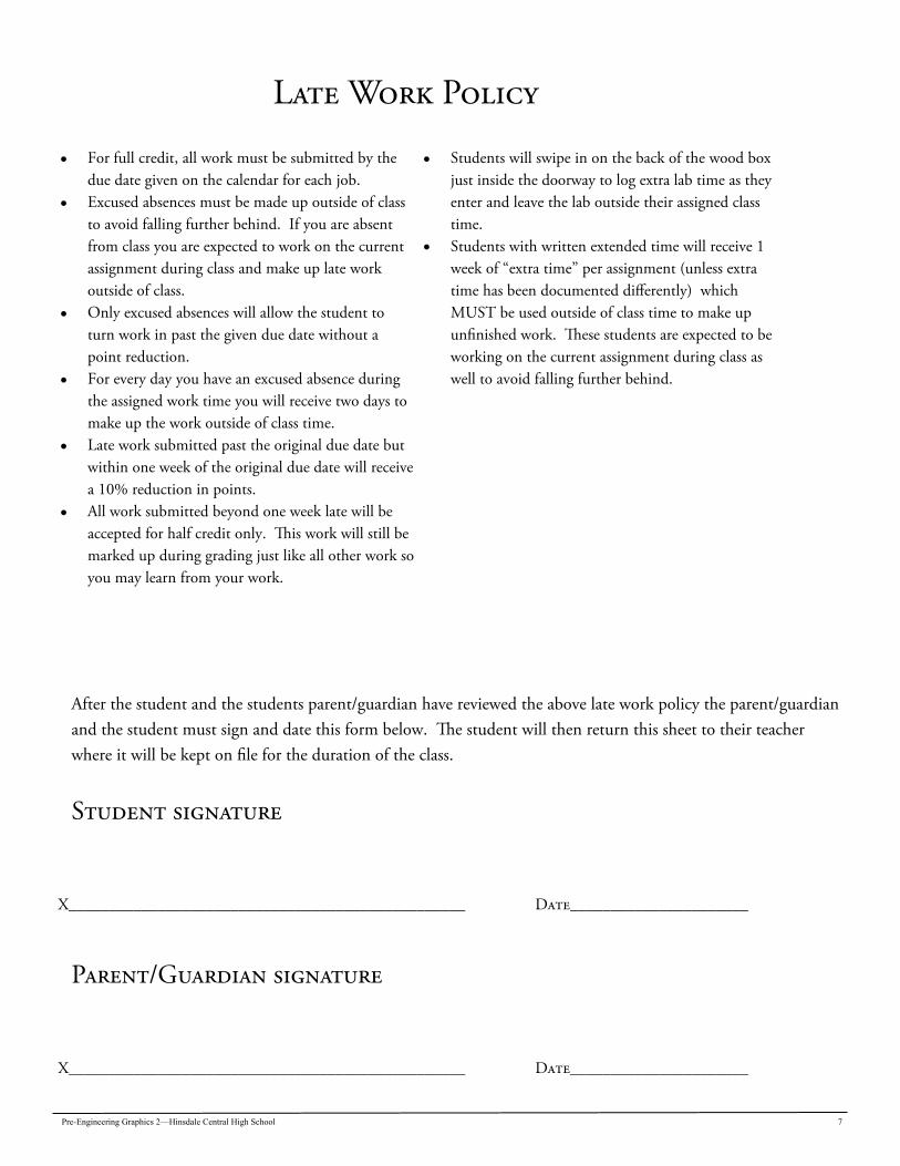
Late Work Policy
For full credit, all work must be submitted by the due date given on the calendar for each job.
Excused absences must be made up outside of class to avoid falling further behind. If you are absent from class you are expected to work on the current assignment during class and make up late work outside of class.
Only excused absences will allow the student to turn work in past the given due date without a point reduction.
For every day you have an excused absence during the assigned work time you will receive two days to make up the work outside of class time.
Late work submitted past the original due date but within one week of the original due date will receive a 10% reduction in points.
All work submitted beyond one week late will be accepted for half credit only. This work will still be marked up during grading just like all other work so you may learn from your work.
Students will swipe in on the back of the wood box just inside the doorway to log extra lab time as they enter and leave the lab outside their assigned class time.
Students with written extended time will receive 1 week of “extra time” per assignment (unless extra time has been documented differently) which MUST be used outside of class time to make up unfinished work. These students are expected to be working on the current assignment during class as well to avoid falling further behind.
After the student and the students parent/guardian have reviewed the above late work policy the parent/guardian and the student must sign and date this form below. The student will then return this sheet to their teacher where it will be kept on file for the duration of the class.
Student signature
X_________________________________________________ Date______________________
Parent/Guardian signature
X_________________________________________________ Date______________________

8 Pre-Engineering Graphics 2—Hinsdale Central High School
Pre-Engineering Graphics 2—Hinsdale Central High School 9
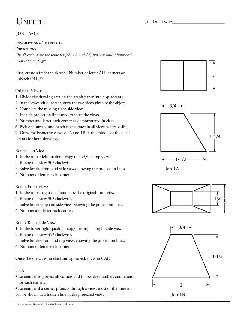
Unit 1: Job 1a-1b
Revoilutions-Chapter 14 Directions: The directions are the same for jobs 1A and 1B, but you will submit each
on it’s own page: First, create a freehand sketch. Number or letter ALL corners on
sketch ONLY: Original Views: 1. Divide the drawing area on the graph paper into 4 quadrants. 2. In the lower left quadrant, draw the two views given of the object. 3. Complete the missing right-side view. 4. Include projection lines used to solve the views. 5. Number and letter each corner as demonstrated in class . 6. Pick one surface and hatch that surface in all views where visible. 7. Draw the Isometric view of 1A and 1B in the middle of the quad-
rants for both drawings. Rotate Top View: 1. In the upper left quadrant copy the original top view 2. Rotate this view 30º clockwise. 3. Solve for the front and side views showing the projection lines. 4. Number or letter each corner. Rotate Front View: 1. In the upper right quadrant copy the original front view 2. Rotate this view 30º clockwise. 3. Solve for the top and side views showing the projection lines. 4. Number and letter each corner. Rotate Right-Side View: 1. In the lower right quadrant copy the original right-side view. 2. Rotate this view 45º clockwise. 3. Solve for the front and top views showing the projection lines. 4. Number or letter each corner. Once the sketch is finished and approved, draw in CAD. Tips: • Remember to project all corners and follow the numbers and letters
for each corner. • Remember if a corner projects through a view, most of the time it will be shown as a hidden line in the projected view.
Job Due Date:________________________
Job 1A
Job 1B
10 Pre-Engineering Graphics 2—Hinsdale Central High School
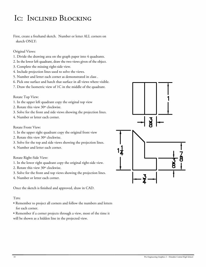
Ic: Inclined Blocking
First, create a freehand sketch. Number or letter ALL corners on sketch ONLY:
Original Views: 1. Divide the drawing area on the graph paper into 4 quadrants. 2. In the lower left quadrant, draw the two views given of the object. 3. Complete the missing right-side view. 4. Include projection lines used to solve the views. 5. Number and letter each corner as demonstrated in class . 6. Pick one surface and hatch that surface in all views where visible. 7. Draw the Isometric view of 1C in the middle of the quadrant. Rotate Top View: 1. In the upper left quadrant copy the original top view 2. Rotate this view 30º clockwise. 3. Solve for the front and side views showing the projection lines. 4. Number or letter each corner. Rotate Front View: 1. In the upper right quadrant copy the original front view 2. Rotate this view 30º clockwise. 3. Solve for the top and side views showing the projection lines. 4. Number and letter each corner. Rotate Right-Side View: 1. In the lower right quadrant copy the original right-side view. 2. Rotate this view 30º clockwise. 3. Solve for the front and top views showing the projection lines. 4. Number or letter each corner. Once the sketch is finished and approved, draw in CAD. Tips: • Remember to project all corners and follow the numbers and letters
for each corner. • Remember if a corner projects through a view, most of the time it will be shown as a hidden line in the projected view.
Pre-Engineering Graphics 2—Hinsdale Central High School 11
Unit 2: Basic Dimensioning Techniques: Chapter 10
For a drawing to be considered complete so that the object represented can be made from it as intended by the designer or engineer, it must tell us two important pieces of infor-mation. It provides (1) views which describe the shape of the object and (2) dimensions and notes which provide infor-mation for manufacturing. Because the object is made based on the information provided in the drawing, any errors will result in an object that is manufactured incorrectly, or delays in the manufacturing process. Professional designers must understand the fundamental manufacturing processes so that they can issue correct instruc-tions through dimensions and notes provided on working drawings. To do this, students must learn the standard prac-tices for dimensioning drawings. In the study of mechanical drafting, dimensioning is an on-going topic as it is not set in stone. Learning about the many different techniques and methods takes a long time and much practice. Only through repetition can a person become famil-iar with the many dimensioning practices, conventions, styles, techniques, and rules. Experience will eventually provide you with the knowledge to make correct dimensioning decisions.
The dimensioning unit is taught in small segments so that the concepts make sense as drawings are completed. In an at-tempt to simplify the dimensioning process, the next page will list some “guide lines” everyone should use while com-pleting the following drawing problems. In addition to the printed guidelines, diagrams are provided to illustrate the concepts as well. You may need to refer to course text and these examples many times, as your instructor will refer you to these pages as well, so look them over care-fully! Dimensioning Systems: Dimensions are placed on the drawing in either a unidirec-tional or an aligned manner: Aligned dimensions are placed parallel to the dimension line. The numerals are read from the bottom and from the right side of the drawing. Unidirectional dimensions are placed to read from the bot-tom of the drawing. Unidirectional dimensioning is generally the preferred system.
12 Pre-Engineering Graphics 2—Hinsdale Central High School
G R D
Use these guidelines to self-check your jobs prior to turning work in. The following pages provide examples to follow as well. For addition information, see Chapter 10 - Dimensioning Techniques, in the course text. 1. Place dimension on views that show the true size/shape of the object. 2. All necessary dimensions needed to determine size/location must be included. 3. Dimensions should be grouped together with associated/like dimensions where possible, size dimensions with size dimen-
sions and location dimensions with location dimensions. 4. Space between dimension lines should be consistent throughout drawing. 5. When ever possible, place dimensions between views. 6. Unless absolutely necessary, dimensions should not be placed within views. 7. Never dimension to a hidden line unless absolutely necessary. 8. Dimension lines should never cross extension lines. 9. If there are several parallel dimensions lines, values should be staggered for readability. 10. Symbols for Diameter, Radius, Countersink, Counterbore, Spot Face should be placed before the dimension. 11. Notes are printed text the same size as the dimension text. 12. Diameter typically associates with FULL circle dimensions, and Radius typically associates with “open” circles or arcs.
13. Always dimension to the Hole itself. You will need a size (diameter) and two location dimensions. 14. When you have a hole to dimension, dimension the height from the base to the center point; not to the top of the hole. We then dimension the diameter of the hole.
Pre-Engineering Graphics 2—Hinsdale Central High School 13
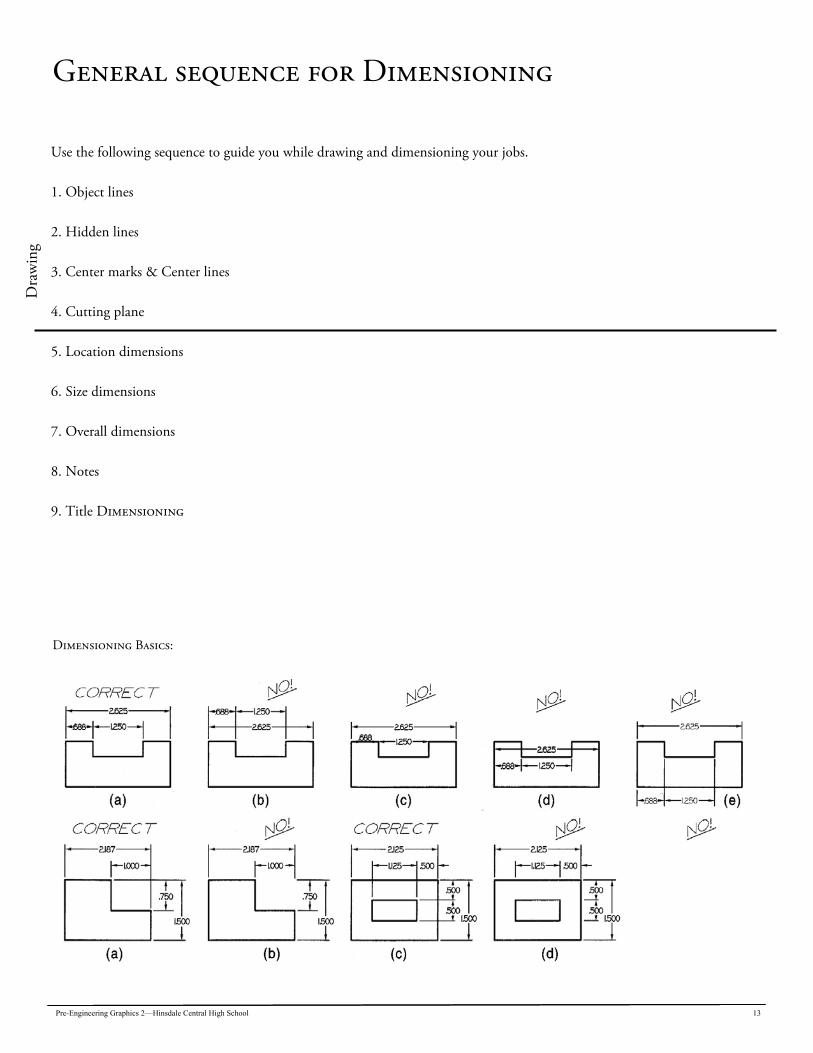
General sequence for Dimensioning D
raw
ing
Use the following sequence to guide you while drawing and dimensioning your jobs. 1. Object lines 2. Hidden lines 3. Center marks & Center lines 4. Cutting plane 5. Location dimensions 6. Size dimensions 7. Overall dimensions 8. Notes 9. Title Dimensioning
Dimensioning Basics:
14 Pre-Engineering Graphics 2—Hinsdale Central High School
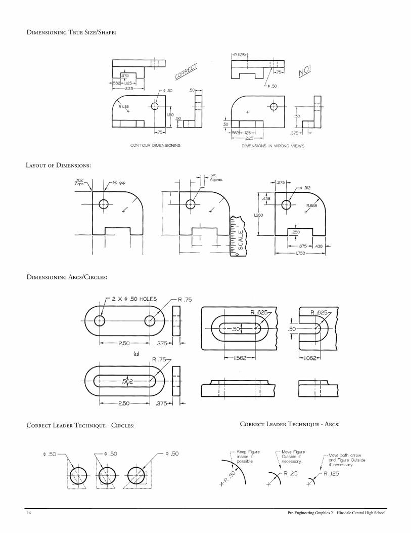
Dimensioning True Size/Shape:
Layout of Dimensions:
Dimensioning Arcs/Circles:
Correct Leader Technique - Circles: Correct Leader Technique - Arcs:
Pre-Engineering Graphics 2—Hinsdale Central High School 15
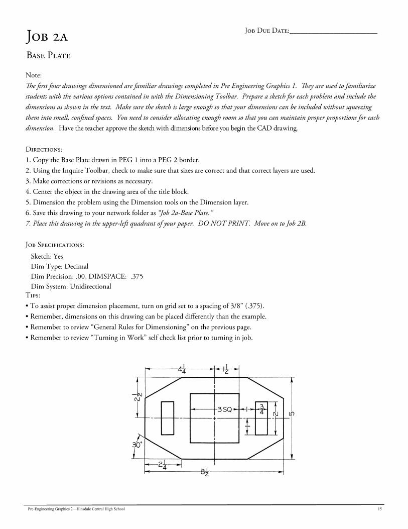
Job 2a Base Plate
Note: The first four drawings dimensioned are familiar drawings completed in Pre Engineering Graphics 1. They are used to familiarize students with the various options contained in with the Dimensioning Toolbar. Prepare a sketch for each problem and include the dimensions as shown in the text. Make sure the sketch is large enough so that your dimensions can be included without squeezing them into small, confined spaces. You need to consider allocating enough room so that you can maintain proper proportions for each dimension. Have the teacher approve the sketch with dimensions before you begin the CAD drawing. Directions: 1. Copy the Base Plate drawn in PEG 1 into a PEG 2 border. 2. Using the Inquire Toolbar, check to make sure that sizes are correct and that correct layers are used. 3. Make corrections or revisions as necessary. 4. Center the object in the drawing area of the title block. 5. Dimension the problem using the Dimension tools on the Dimension layer. 6. Save this drawing to your network folder as “Job 2a-Base Plate.” 7. Place this drawing in the upper-left quadrant of your paper. DO NOT PRINT. Move on to Job 2B. Job Specifications:
Sketch: Yes Dim Type: Decimal Dim Precision: .00, DIMSPACE: .375 Dim System: Unidirectional
Tips: • To assist proper dimension placement, turn on grid set to a spacing of 3/8” (.375). • Remember, dimensions on this drawing can be placed differently than the example. • Remember to review “General Rules for Dimensioning” on the previous page. • Remember to review “Turning in Work” self check list prior to turning in job.
Job Due Date:________________________
16 Pre-Engineering Graphics 2—Hinsdale Central High School
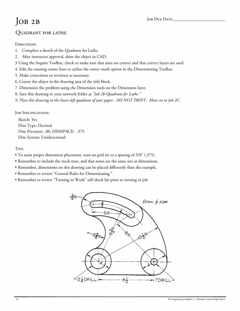
Job 2b Quadrant for lathe
Directions: 1. Complete a sketch of the Quadrant for Lathe. 2. After instructor approval, draw the object in CAD. 3 Using the Inquire Toolbar, check to make sure that sizes are correct and that correct layers are used. 4. Edit the existing center lines to utilize the center mark option in the Dimensioning Toolbar. 5. Make corrections or revisions as necessary. 6. Center the object in the drawing area of the title block. 7. Dimension the problem using the Dimension tools on the Dimension layer. 8. Save this drawing to your network folder as “Job 2b-Quadrant for Lathe.” 9. Place this drawing in the lower-left quadrant of your paper. DO NOT PRINT. Move on to Job 2C. Job Specifications:
Sketch: Yes Dim Type: Decimal Dim Precision: .00, DIMSPACE: .375 Dim System: Unidirectional
Tips: • To assist proper dimension placement, turn on grid set to a spacing of 3/8” (.375). • Remember to include the stock note, and that notes are the same size as dimensions. • Remember, dimensions on this drawing can be placed differently than the example. • Remember to review “General Rules for Dimensioning.” • Remember to review “Turning in Work” self check list prior to turning in job.
Job Due Date:________________________
Pre-Engineering Graphics 2—Hinsdale Central High School 17
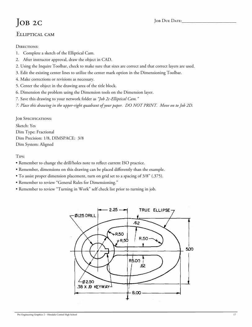
Job 2c Elliptical cam
Directions: 1. Complete a sketch of the Elliptical Cam. 2. After instructor approval, draw the object in CAD. 2. Using the Inquire Toolbar, check to make sure that sizes are correct and that correct layers are used. 3. Edit the existing center lines to utilize the center mark option in the Dimensioning Toolbar. 4. Make corrections or revisions as necessary. 5. Center the object in the drawing area of the title block. 6. Dimension the problem using the Dimension tools on the Dimension layer. 7. Save this drawing to your network folder as “Job 2c-Elliptical Cam.” 7. Place this drawing in the upper-right quadrant of your paper. DO NOT PRINT. Move on to Job 2D. Job Specifications:
Sketch: Yes Dim Type: Fractional Dim Precision: 1/8, DIMSPACE: 3/8 Dim System: Aligned Tips: • Remember to change the drill/holes note to reflect current ISO practice. • Remember, dimensions on this drawing can be placed differently than the example. • To assist proper dimension placement, turn on grid set to a spacing of 3/8” (.375). • Remember to review “General Rules for Dimensioning.” • Remember to review “Turning in Work” self check list prior to turning in job.
Job Due Date:________________________
18 Pre-Engineering Graphics 2—Hinsdale Central High School
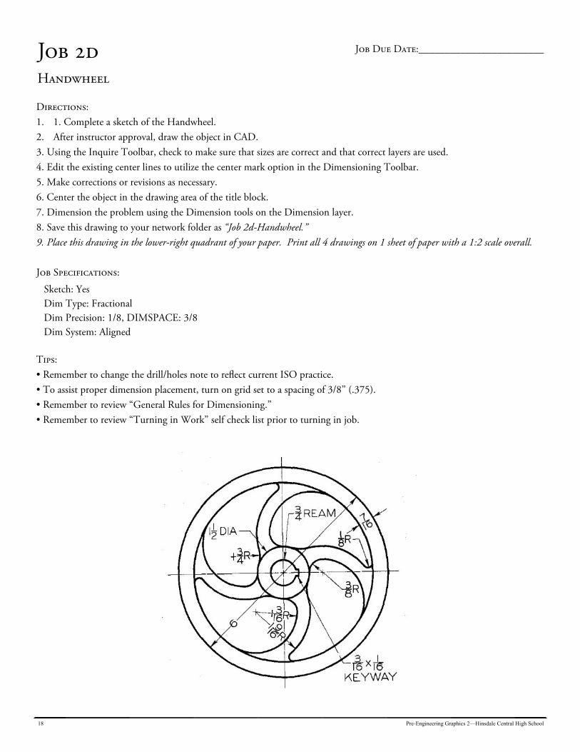
Job 2d Handwheel
Directions: 1. 1. Complete a sketch of the Handwheel. 2. After instructor approval, draw the object in CAD. 3. Using the Inquire Toolbar, check to make sure that sizes are correct and that correct layers are used. 4. Edit the existing center lines to utilize the center mark option in the Dimensioning Toolbar. 5. Make corrections or revisions as necessary. 6. Center the object in the drawing area of the title block. 7. Dimension the problem using the Dimension tools on the Dimension layer. 8. Save this drawing to your network folder as “Job 2d-Handwheel.” 9. Place this drawing in the lower-right quadrant of your paper. Print all 4 drawings on 1 sheet of paper with a 1:2 scale overall. Job Specifications:
Sketch: Yes Dim Type: Fractional Dim Precision: 1/8, DIMSPACE: 3/8 Dim System: Aligned
Tips: • Remember to change the drill/holes note to reflect current ISO practice. • To assist proper dimension placement, turn on grid set to a spacing of 3/8” (.375). • Remember to review “General Rules for Dimensioning.” • Remember to review “Turning in Work” self check list prior to turning in job.
Job Due Date:________________________
Pre-Engineering Graphics 2—Hinsdale Central High School 19
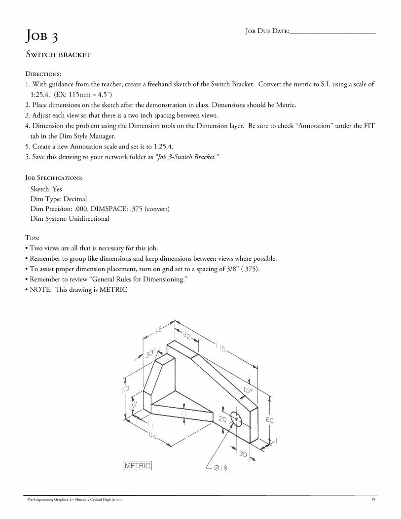
Job 3 Switch bracket
Directions: 1. With guidance from the teacher, create a freehand sketch of the Switch Bracket. Convert the metric to S.I. using a scale of
1:25.4. (EX: 115mm = 4.5”) 2. Place dimensions on the sketch after the demonstration in class. Dimensions should be Metric. 3. Adjust each view so that there is a two inch spacing between views. 4. Dimension the problem using the Dimension tools on the Dimension layer. Be sure to check “Annotation” under the FIT
tab in the Dim Style Manager. 5. Create a new Annotation scale and set it to 1:25.4. 5. Save this drawing to your network folder as “Job 3-Switch Bracket.” Job Specifications:
Sketch: Yes Dim Type: Decimal Dim Precision: .000, DIMSPACE: .375 (convert) Dim System: Unidirectional
Tips: • Two views are all that is necessary for this job. • Remember to group like dimensions and keep dimensions between views where possible. • To assist proper dimension placement, turn on grid set to a spacing of 3/8” (.375). • Remember to review “General Rules for Dimensioning.” • NOTE: This drawing is METRIC
Job Due Date:________________________
20 Pre-Engineering Graphics 2—Hinsdale Central High School
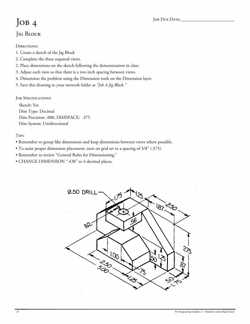
Job 4 Jig Block
Directions: 1. Create a sketch of the Jig Block 2. Complete the three required views. 2. Place dimensions on the sketch following the demonstration in class. 3. Adjust each view so that there is a two inch spacing between views. 4. Dimension the problem using the Dimension tools on the Dimension layer. 5. Save this drawing to your network folder as “Job 4-Jig Block.” Job Specifications:
Sketch: Yes Dim Type: Decimal Dim Precision: .000, DIMSPACE: .375 Dim System: Unidirectional
Tips: • Remember to group like dimensions and keep dimensions between views where possible. • To assist proper dimension placement, turn on grid set to a spacing of 3/8” (.375). • Remember to review “General Rules for Dimensioning.” • CHANGE DIMENSION “.438” to 4 decimal places.
Job Due Date:________________________
Pre-Engineering Graphics 2—Hinsdale Central High School 21
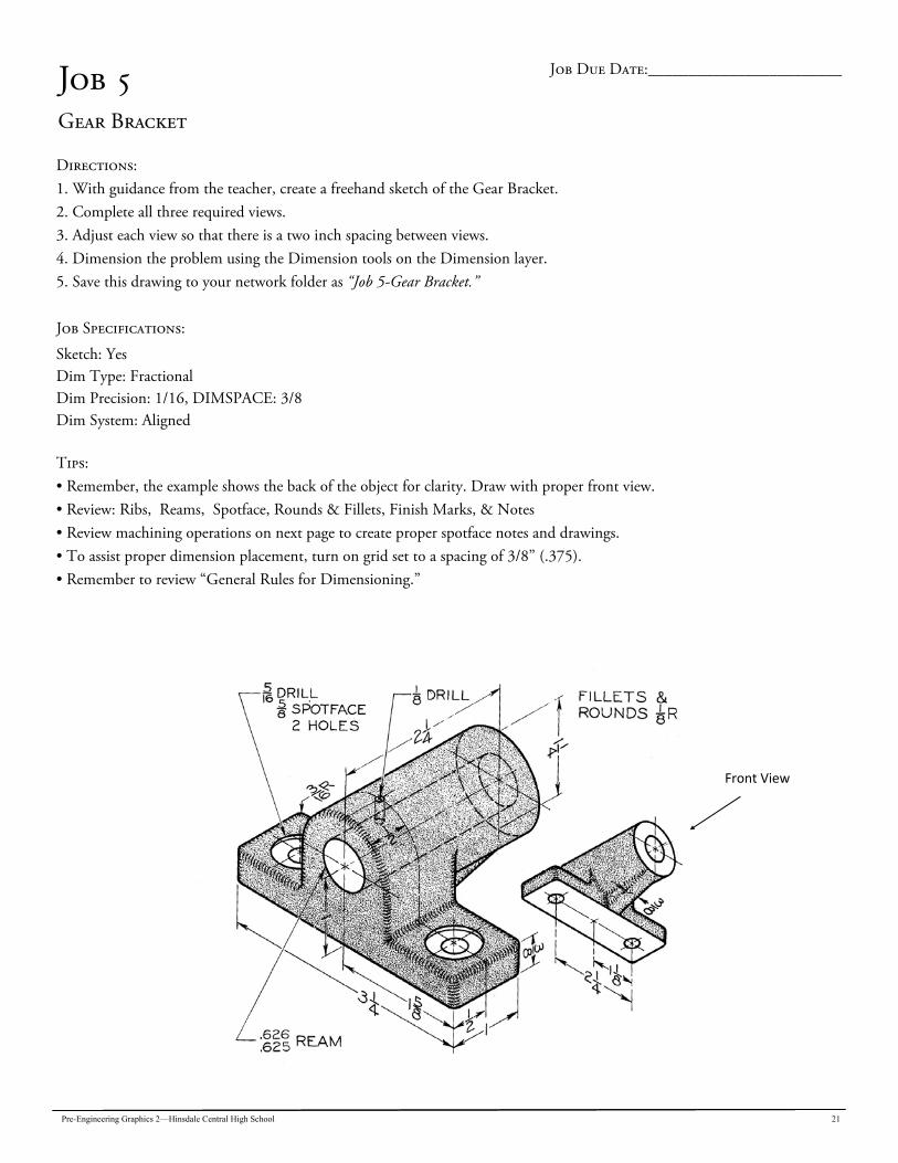
Job 5 Gear Bracket
Directions: 1. With guidance from the teacher, create a freehand sketch of the Gear Bracket. 2. Complete all three required views. 3. Adjust each view so that there is a two inch spacing between views. 4. Dimension the problem using the Dimension tools on the Dimension layer. 5. Save this drawing to your network folder as “Job 5-Gear Bracket.” Job Specifications:
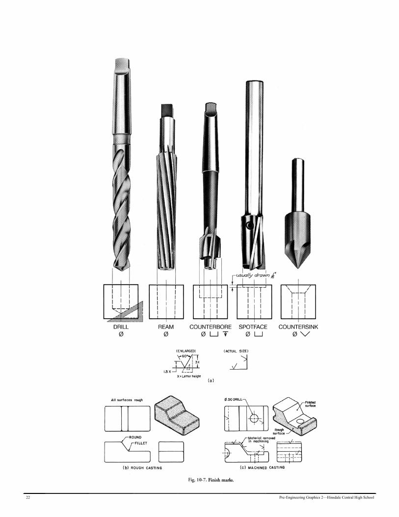
Sketch: Yes Dim Type: Fractional Dim Precision: 1/16, DIMSPACE: 3/8 Dim System: Aligned Tips: • Remember, the example shows the back of the object for clarity. Draw with proper front view. • Review: Ribs, Reams, Spotface, Rounds & Fillets, Finish Marks, & Notes • Review machining operations on next page to create proper spotface notes and drawings. • To assist proper dimension placement, turn on grid set to a spacing of 3/8” (.375). • Remember to review “General Rules for Dimensioning.”
Job Due Date:________________________
Front View
22 Pre-Engineering Graphics 2—Hinsdale Central High School

Pre-Engineering Graphics 2—Hinsdale Central High School 23

24 Pre-Engineering Graphics 2—Hinsdale Central High School
Unit 3: Limit Dimensioning Techniques: Chapter 10, p. 213
Interchangeable manufacturing means that two or more different parts, manufactured in different locations, will be similar enough to fit satisfactorily together. If parts of mechanisms are to work as they should, the dimensions of one part must work with the dimensions of another part. In other words, the dimensions must be within certain limits. Tolerance & Allowance The specific definitions that all engineering students need to understand are Tolerance and Allowance: Tolerance is the total permissible variation of a size, or the diflerence between the limits of size. In example “b” below, the tolerance of the hole is between 1.501 and 1.500, for a tolerance of .001. Allowance is the intentional diflerence between the maximum material limits of mating parts. Again, using the hole in example “b” below, the largest shaft dimension is 1.498. The smallest hole dimension allowed is 1.500. The difference, .002, is the allow-ance. Classes of Fit Fit is the general term used to signify the range of tightness that may result from a specific combination of allowances and tolerances in the design of mating parts. Fits are of three general types: clearance, transition, and interference. Clearance ‥ts always have space (clearance) between mating parts as a result of their allowance. Interference ‥ts always result in mating parts overlap (interfere) as the result of their allowance. Transition ‥ts have allowances that can result in either a clearance or interference ‥t.
Pre-Engineering Graphics 2—Hinsdale Central High School 25
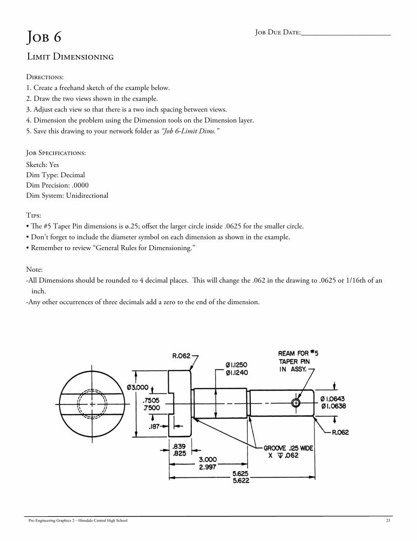
Job 6 Limit Dimensioning
Directions: 1. Create a freehand sketch of the example below. 2. Draw the two views shown in the example. 3. Adjust each view so that there is a two inch spacing between views. 4. Dimension the problem using the Dimension tools on the Dimension layer. 5. Save this drawing to your network folder as “Job 6-Limit Dims.” Job Specifications:
Sketch: Yes Dim Type: Decimal Dim Precision: .0000 Dim System: Unidirectional Tips: • The #5 Taper Pin dimensions is ø.25; offset the larger circle inside .0625 for the smaller circle. • Don’t forget to include the diameter symbol on each dimension as shown in the example. • Remember to review “General Rules for Dimensioning.” Note: -All Dimensions should be rounded to 4 decimal places. This will change the .062 in the drawing to .0625 or 1/16th of an
inch. -Any other occurrences of three decimals add a zero to the end of the dimension.
Job Due Date:________________________
26 Pre-Engineering Graphics 2—Hinsdale Central High School
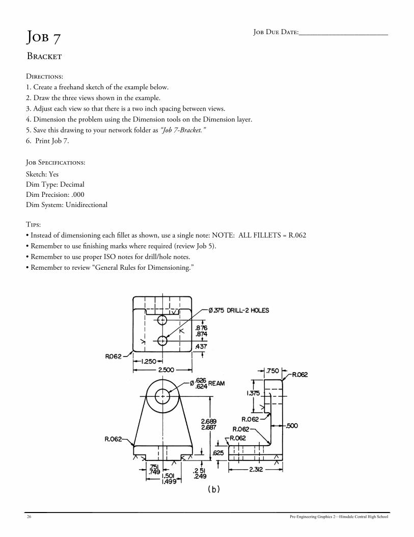
Job 7 Bracket
Directions: 1. Create a freehand sketch of the example below. 2. Draw the three views shown in the example. 3. Adjust each view so that there is a two inch spacing between views. 4. Dimension the problem using the Dimension tools on the Dimension layer. 5. Save this drawing to your network folder as “Job 7-Bracket.” 6. Print Job 7. Job Specifications:
Sketch: Yes Dim Type: Decimal Dim Precision: .000 Dim System: Unidirectional Tips: • Instead of dimensioning each fillet as shown, use a single note: NOTE: ALL FILLETS = R.062 • Remember to use finishing marks where required (review Job 5). • Remember to use proper ISO notes for drill/hole notes. • Remember to review “General Rules for Dimensioning.”
Job Due Date:________________________
Pre-Engineering Graphics 2—Hinsdale Central High School 27
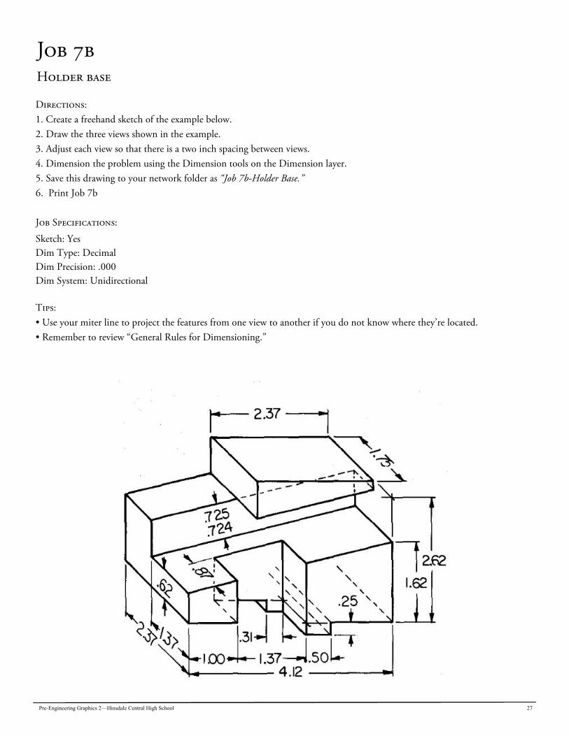
Job 7b Holder base
Directions: 1. Create a freehand sketch of the example below. 2. Draw the three views shown in the example. 3. Adjust each view so that there is a two inch spacing between views. 4. Dimension the problem using the Dimension tools on the Dimension layer. 5. Save this drawing to your network folder as “Job 7b-Holder Base.” 6. Print Job 7b Job Specifications:
Sketch: Yes Dim Type: Decimal Dim Precision: .000 Dim System: Unidirectional Tips: • Use your miter line to project the features from one view to another if you do not know where they’re located. • Remember to review “General Rules for Dimensioning.”
28 Pre-Engineering Graphics 2—Hinsdale Central High School
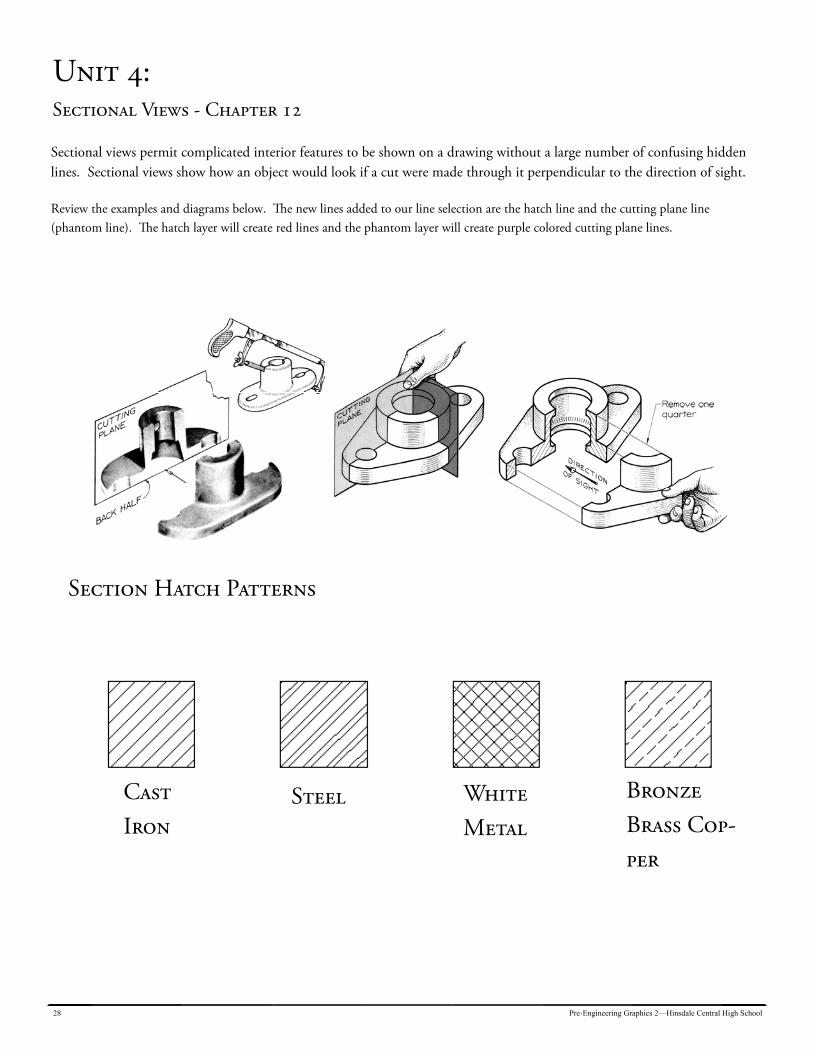
Unit 4: Sectional Views - Chapter 12
Sectional views permit complicated interior features to be shown on a drawing without a large number of confusing hidden lines. Sectional views show how an object would look if a cut were made through it perpendicular to the direction of sight. Review the examples and diagrams below. The new lines added to our line selection are the hatch line and the cutting plane line (phantom line). The hatch layer will create red lines and the phantom layer will create purple colored cutting plane lines.
Section Hatch Patterns
Cast Iron
Steel White Metal
Bronze Brass Cop-per
Pre-Engineering Graphics 2—Hinsdale Central High School 29
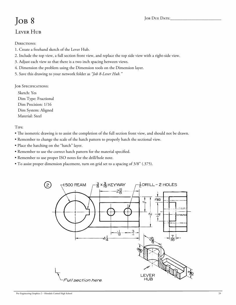
Job 8 Lever Hub
Directions: 1. Create a freehand sketch of the Lever Hub. 2. Include the top view, a full section front view, and replace the top side view with a right-side view. 3. Adjust each view so that there is a two inch spacing between views. 4. Dimension the problem using the Dimension tools on the Dimension layer. 5. Save this drawing to your network folder as “Job 8-Lever Hub.” Job Specifications:
Sketch: Yes Dim Type: Fractional Dim Precision: 1/16 Dim System: Aligned Material: Steel
Tips: • The isometric drawing is to assist the completion of the full section front view, and should not be drawn. • Remember to change the scale of the hatch pattern to properly hatch the sectional view. • Place the hatching on the “hatch” layer. • Remember to use the correct hatch pattern for the material specified. • Remember to use proper ISO notes for the drill/hole note. • To assist proper dimension placement, turn on grid set to a spacing of 3/8” (.375).
Job Due Date:________________________
30 Pre-Engineering Graphics 2—Hinsdale Central High School
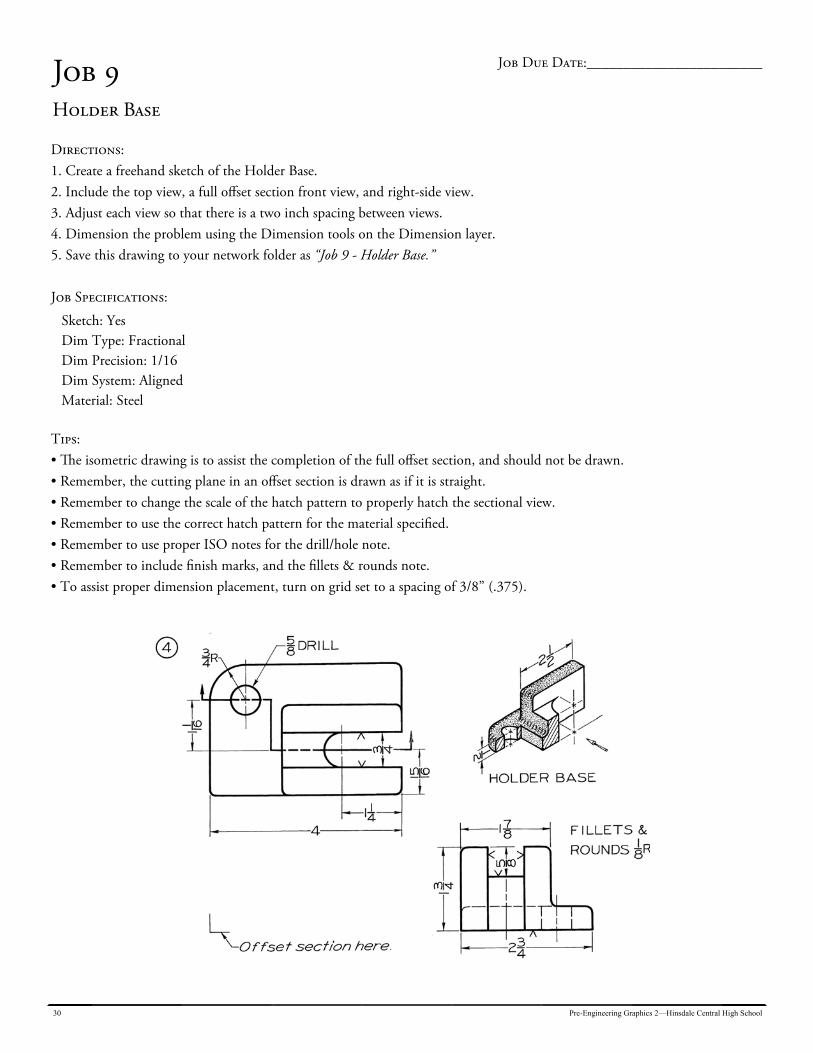
Job 9 Holder Base
Directions: 1. Create a freehand sketch of the Holder Base. 2. Include the top view, a full offset section front view, and right-side view. 3. Adjust each view so that there is a two inch spacing between views. 4. Dimension the problem using the Dimension tools on the Dimension layer. 5. Save this drawing to your network folder as “Job 9 - Holder Base.” Job Specifications:
Sketch: Yes Dim Type: Fractional Dim Precision: 1/16 Dim System: Aligned Material: Steel
Tips: • The isometric drawing is to assist the completion of the full offset section, and should not be drawn. • Remember, the cutting plane in an offset section is drawn as if it is straight. • Remember to change the scale of the hatch pattern to properly hatch the sectional view. • Remember to use the correct hatch pattern for the material specified. • Remember to use proper ISO notes for the drill/hole note. • Remember to include finish marks, and the fillets & rounds note. • To assist proper dimension placement, turn on grid set to a spacing of 3/8” (.375).
Job Due Date:________________________
Pre-Engineering Graphics 2—Hinsdale Central High School 31
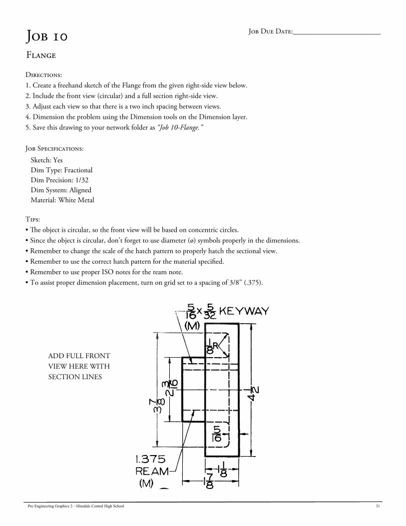
Job 10 Flange
Directions: 1. Create a freehand sketch of the Flange from the given right-side view below. 2. Include the front view (circular) and a full section right-side view. 3. Adjust each view so that there is a two inch spacing between views. 4. Dimension the problem using the Dimension tools on the Dimension layer. 5. Save this drawing to your network folder as “Job 10-Flange.” Job Specifications:
Sketch: Yes Dim Type: Fractional Dim Precision: 1/32 Dim System: Aligned Material: White Metal
Tips: • The object is circular, so the front view will be based on concentric circles. • Since the object is circular, don’t forget to use diameter (ø) symbols properly in the dimensions. • Remember to change the scale of the hatch pattern to properly hatch the sectional view. • Remember to use the correct hatch pattern for the material specified. • Remember to use proper ISO notes for the ream note. • To assist proper dimension placement, turn on grid set to a spacing of 3/8” (.375).
Job Due Date:________________________
ADD FULL FRONT VIEW HERE WITH SECTION LINES
32 Pre-Engineering Graphics 2—Hinsdale Central High School
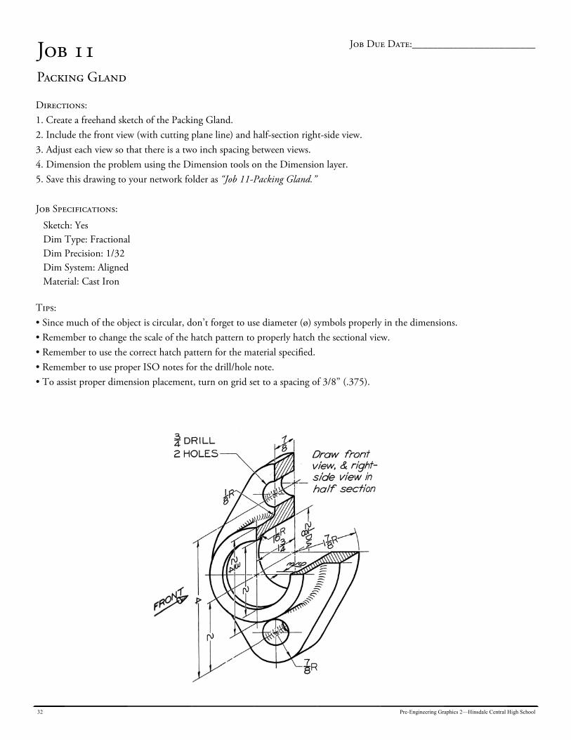
Job 11 Packing Gland
Directions: 1. Create a freehand sketch of the Packing Gland. 2. Include the front view (with cutting plane line) and half-section right-side view. 3. Adjust each view so that there is a two inch spacing between views. 4. Dimension the problem using the Dimension tools on the Dimension layer. 5. Save this drawing to your network folder as “Job 11-Packing Gland.” Job Specifications:
Sketch: Yes Dim Type: Fractional Dim Precision: 1/32 Dim System: Aligned Material: Cast Iron
Tips: • Since much of the object is circular, don’t forget to use diameter (ø) symbols properly in the dimensions. • Remember to change the scale of the hatch pattern to properly hatch the sectional view. • Remember to use the correct hatch pattern for the material specified. • Remember to use proper ISO notes for the drill/hole note. • To assist proper dimension placement, turn on grid set to a spacing of 3/8” (.375).
Job Due Date:________________________
Pre-Engineering Graphics 2—Hinsdale Central High School 33
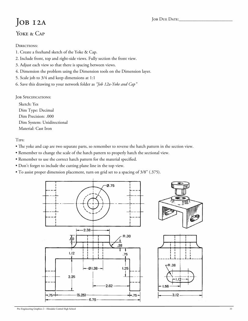
Job 12a Yoke & Cap
Directions: 1. Create a freehand sketch of the Yoke & Cap. 2. Include front, top and right-side views. Fully section the front view. 3. Adjust each view so that there is spacing between views. 4. Dimension the problem using the Dimension tools on the Dimension layer. 5. Scale job to 3/4 and keep dimensions at 1:1 6. Save this drawing to your network folder as “Job 12a-Yoke and Cap” Job Specifications:
Sketch: Yes Dim Type: Decimal Dim Precision: .000 Dim System: Unidirectional Material: Cast Iron
Tips: • The yoke and cap are two separate parts, so remember to reverse the hatch pattern in the section view. • Remember to change the scale of the hatch pattern to properly hatch the sectional view. • Remember to use the correct hatch pattern for the material specified. • Don’t forget to include the cutting plane line in the top view. • To assist proper dimension placement, turn on grid set to a spacing of 3/8” (.375).
Job Due Date:________________________
34 Pre-Engineering Graphics 2—Hinsdale Central High School
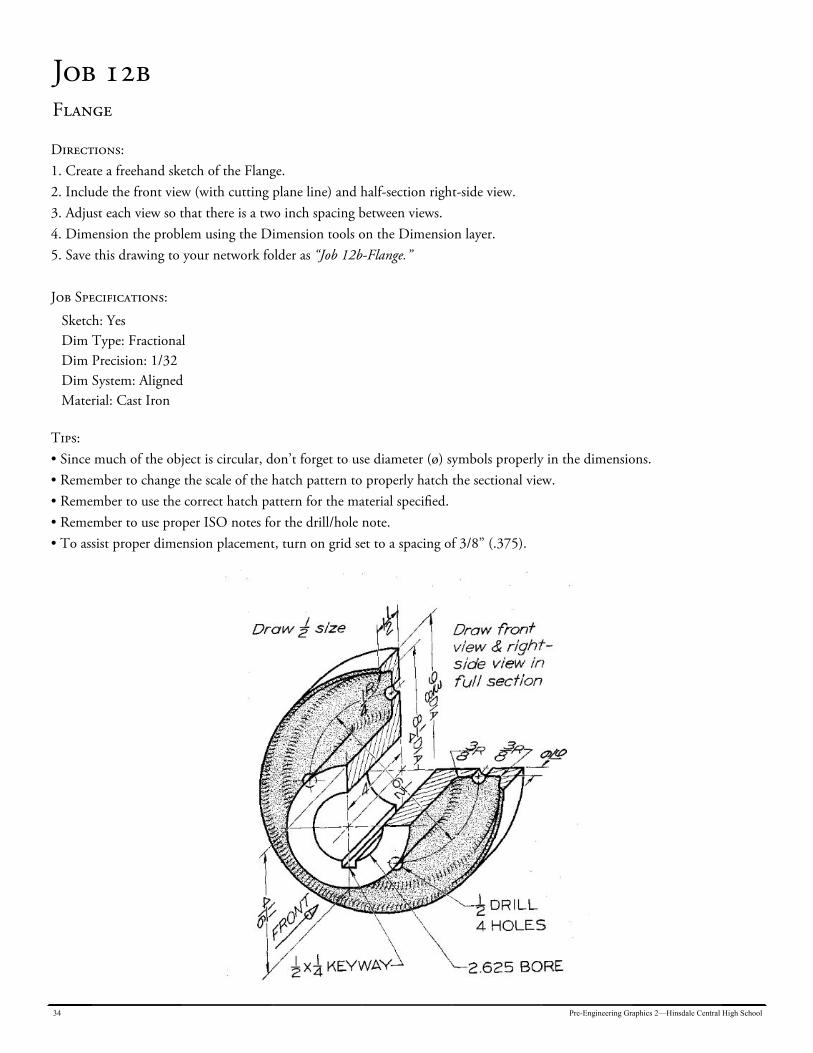
Job 12b Flange
Directions: 1. Create a freehand sketch of the Flange. 2. Include the front view (with cutting plane line) and half-section right-side view. 3. Adjust each view so that there is a two inch spacing between views. 4. Dimension the problem using the Dimension tools on the Dimension layer. 5. Save this drawing to your network folder as “Job 12b-Flange.” Job Specifications:
Sketch: Yes Dim Type: Fractional Dim Precision: 1/32 Dim System: Aligned Material: Cast Iron
Tips: • Since much of the object is circular, don’t forget to use diameter (ø) symbols properly in the dimensions. • Remember to change the scale of the hatch pattern to properly hatch the sectional view. • Remember to use the correct hatch pattern for the material specified. • Remember to use proper ISO notes for the drill/hole note. • To assist proper dimension placement, turn on grid set to a spacing of 3/8” (.375).
Pre-Engineering Graphics 2—Hinsdale Central High School 35
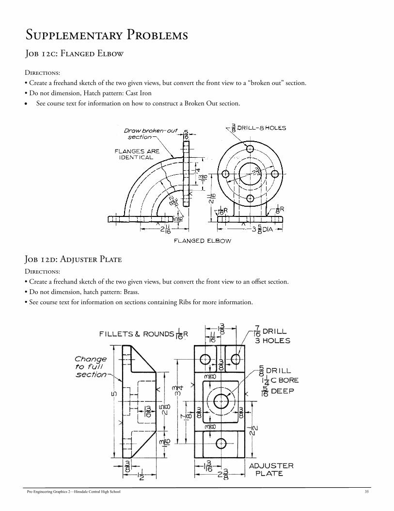
Supplementary Problems Job 12c: Flanged Elbow
Directions: • Create a freehand sketch of the two given views, but convert the front view to a “broken out” section. • Do not dimension, Hatch pattern: Cast Iron See course text for information on how to construct a Broken Out section.
Job 12d: Adjuster Plate Directions: • Create a freehand sketch of the two given views, but convert the front view to an offset section. • Do not dimension, hatch pattern: Brass. • See course text for information on sections containing Ribs for more information.
36 Pre-Engineering Graphics 2—Hinsdale Central High School
Unit 5: Auxiliary Views - Chapter 13
Many objects have surfaces that are inclined to the line of sight. When this occurs in the principle views (front, top, and right-side), some of the inclined surfaces will not be shown in their true size or true shape. Because the surfaces are slanted (inclined) to the line of sight, distortion of that surface results. Each view in a 3-view drawing is drawn to be “true size and shape”. We make an assumption that we are looking at each view straight on so that our line of sight makes is 90 degree, or perpendicular, with each view of the object. For example, think of looking a house from the street. When you stand directly in front of the house, you are looking at the front wall (front view) at a perpendicular angle. That means that the image of the front of the house is entering your eye at a right angle. However, the roof of the home is slanted so that rain water can run down to the gutter. That roof surface, because it is inclined is slanting away from you and you are not looking at it from a right angle. The roof surface that you are looking at is said to be “foreshortened”. Any surface drawn on paper or the computer that slants away from your line of sight (or slants toward your line of sight) cannot be drawn accurately in its true size or shape as it results in the foreshortening of the surface. To solve this problem, auxiliary views are drawn.
The three views of a multi-view drawing are intended to show each view in its true size and shape. When one or more of the views has an inclined surface, true size and true shape is shown through creation of an auxiliary view. Auxiliary views show surfaces in their true size and true shape. In the process of making auxiliary views, it is often necessary to omit one of the three principle views. The view omitted is replaced by the auxiliary view. Auxiliary views are always drawn at a right angle to the inclined surface they depict. Just as projection from the front view to the top and side views is used in conventional orthographic drawing to create various views, projection from the inclined surface in any view is also used to create the auxiliary view.
Pre-Engineering Graphics 2—Hinsdale Central High School 37
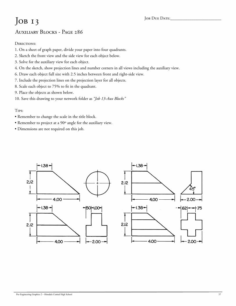
Job 13 Auxiliary Blocks - Page 286
Directions: 1. On a sheet of graph paper, divide your paper into four quadrants. 2. Sketch the front view and the side view for each object below. 3. Solve for the auxiliary view for each object. 4. On the sketch, show projection lines and number corners in all views including the auxiliary view. 6. Draw each object full size with 2.5 inches between front and right-side view. 7. Include the projection lines on the projection layer for all objects. 8. Scale each object to 75% to fit in the quadrant. 9. Place the objects as shown below. 10. Save this drawing to your network folder as “Job 13-Aux Blocks”
Tips: • Remember to change the scale in the title block. • Remember to project at a 90º angle for the auxiliary view. • Dimensions are not required on this job.
Job Due Date:________________________
38 Pre-Engineering Graphics 2—Hinsdale Central High School
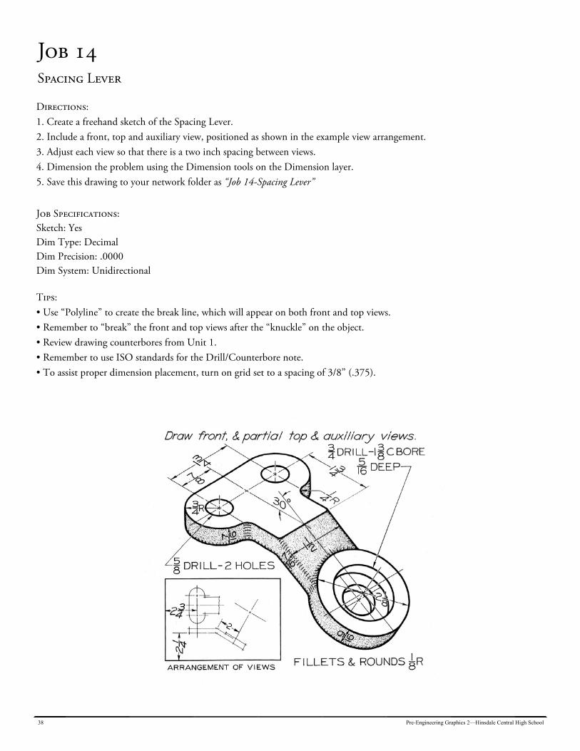
Job 14 Spacing Lever
Directions: 1. Create a freehand sketch of the Spacing Lever. 2. Include a front, top and auxiliary view, positioned as shown in the example view arrangement. 3. Adjust each view so that there is a two inch spacing between views. 4. Dimension the problem using the Dimension tools on the Dimension layer. 5. Save this drawing to your network folder as “Job 14-Spacing Lever”
Job Specifications: Sketch: Yes Dim Type: Decimal Dim Precision: .0000 Dim System: Unidirectional
Tips: • Use “Polyline” to create the break line, which will appear on both front and top views. • Remember to “break” the front and top views after the “knuckle” on the object. • Review drawing counterbores from Unit 1. • Remember to use ISO standards for the Drill/Counterbore note. • To assist proper dimension placement, turn on grid set to a spacing of 3/8” (.375).
Pre-Engineering Graphics 2—Hinsdale Central High School 39
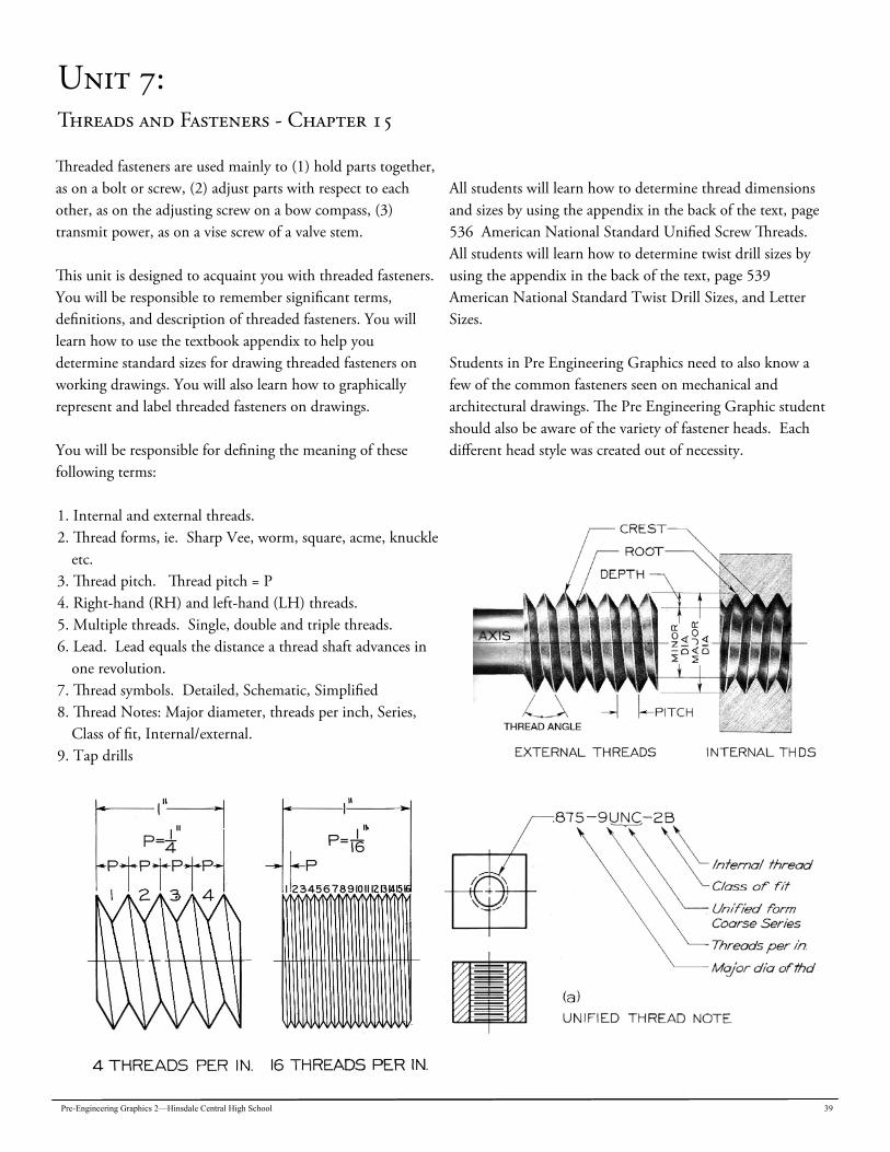
Unit 7: Threads and Fasteners - Chapter 15
Threaded fasteners are used mainly to (1) hold parts together, as on a bolt or screw, (2) adjust parts with respect to each other, as on the adjusting screw on a bow compass, (3) transmit power, as on a vise screw of a valve stem. This unit is designed to acquaint you with threaded fasteners. You will be responsible to remember significant terms, definitions, and description of threaded fasteners. You will learn how to use the textbook appendix to help you determine standard sizes for drawing threaded fasteners on working drawings. You will also learn how to graphically represent and label threaded fasteners on drawings. You will be responsible for defining the meaning of these following terms: 1. Internal and external threads. 2. Thread forms, ie. Sharp Vee, worm, square, acme, knuckle
etc. 3. Thread pitch. Thread pitch = P 4. Right-hand (RH) and left-hand (LH) threads. 5. Multiple threads. Single, double and triple threads. 6. Lead. Lead equals the distance a thread shaft advances in
one revolution. 7. Thread symbols. Detailed, Schematic, Simplified 8. Thread Notes: Major diameter, threads per inch, Series,
Class of fit, Internal/external. 9. Tap drills
All students will learn how to determine thread dimensions and sizes by using the appendix in the back of the text, page 536 American National Standard Unified Screw Threads. All students will learn how to determine twist drill sizes by using the appendix in the back of the text, page 539 American National Standard Twist Drill Sizes, and Letter Sizes. Students in Pre Engineering Graphics need to also know a few of the common fasteners seen on mechanical and architectural drawings. The Pre Engineering Graphic student should also be aware of the variety of fastener heads. Each different head style was created out of necessity.
40 Pre-Engineering Graphics 2—Hinsdale Central High School
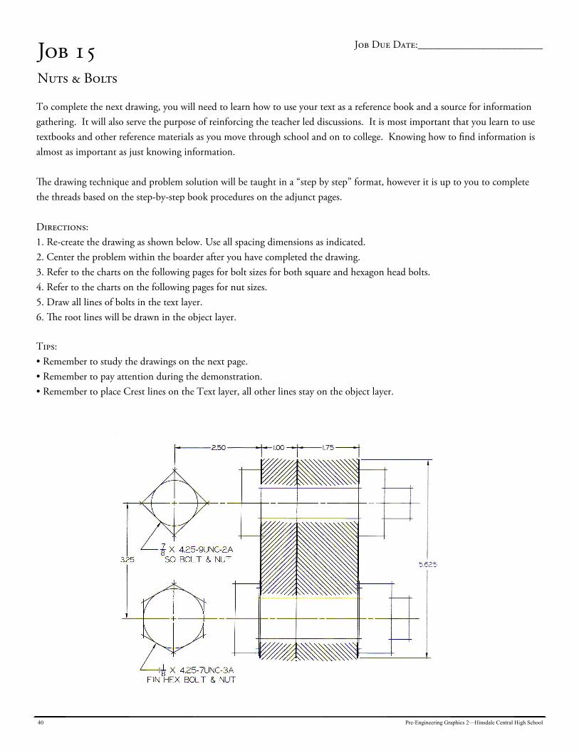
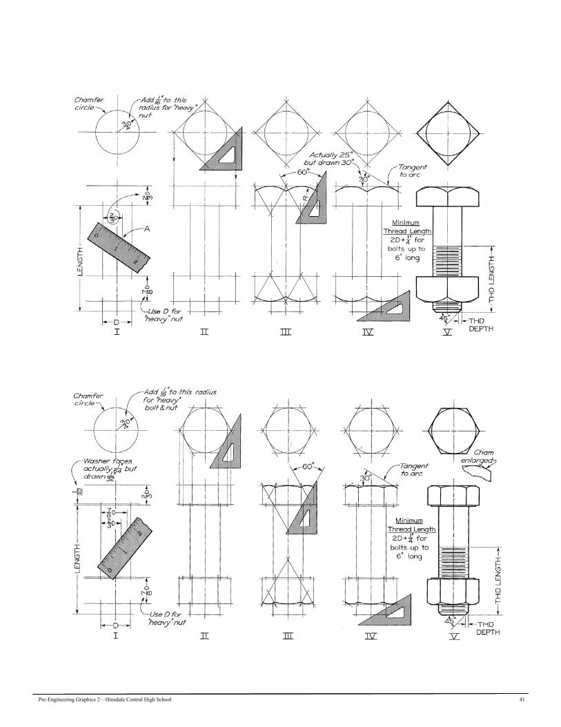
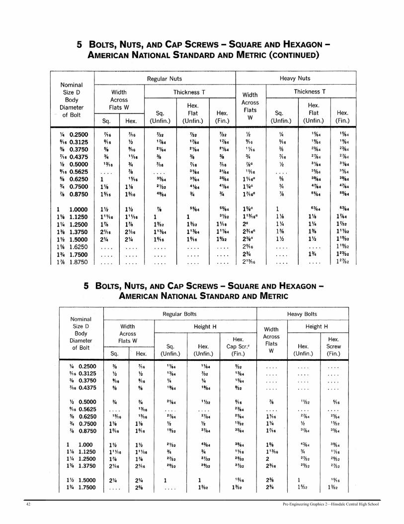
Job 15 Nuts & Bolts
To complete the next drawing, you will need to learn how to use your text as a reference book and a source for information gathering. It will also serve the purpose of reinforcing the teacher led discussions. It is most important that you learn to use textbooks and other reference materials as you move through school and on to college. Knowing how to find information is almost as important as just knowing information. The drawing technique and problem solution will be taught in a “step by step” format, however it is up to you to complete the threads based on the step-by-step book procedures on the adjunct pages. Directions: 1. Re-create the drawing as shown below. Use all spacing dimensions as indicated. 2. Center the problem within the boarder after you have completed the drawing. 3. Refer to the charts on the following pages for bolt sizes for both square and hexagon head bolts. 4. Refer to the charts on the following pages for nut sizes. 5. Draw all lines of bolts in the text layer. 6. The root lines will be drawn in the object layer.
Tips: • Remember to study the drawings on the next page. • Remember to pay attention during the demonstration. • Remember to place Crest lines on the Text layer, all other lines stay on the object layer.
Job Due Date:________________________
Pre-Engineering Graphics 2—Hinsdale Central High School 41
42 Pre-Engineering Graphics 2—Hinsdale Central High School

Pre-Engineering Graphics 2—Hinsdale Central High School 43
44 Pre-Engineering Graphics 2—Hinsdale Central High School
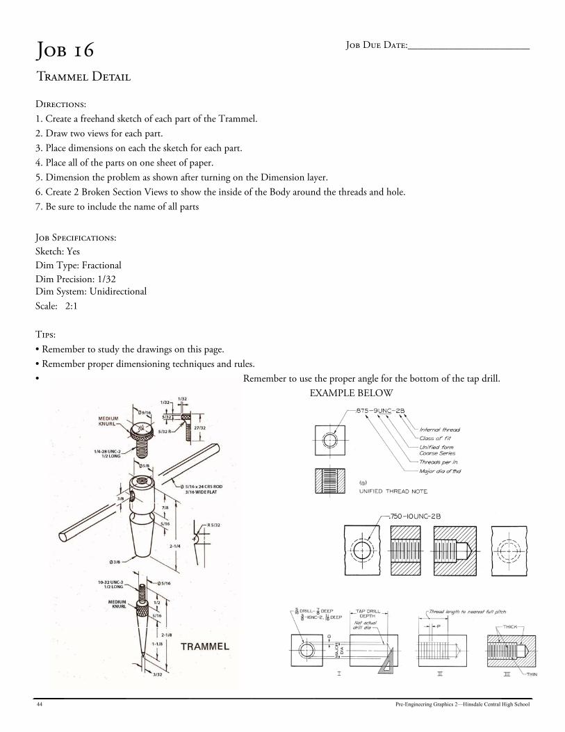
Job 16 Trammel Detail
Directions: 1. Create a freehand sketch of each part of the Trammel. 2. Draw two views for each part. 3. Place dimensions on each the sketch for each part. 4. Place all of the parts on one sheet of paper. 5. Dimension the problem as shown after turning on the Dimension layer. 6. Create 2 Broken Section Views to show the inside of the Body around the threads and hole. 7. Be sure to include the name of all parts
Job Specifications: Sketch: Yes Dim Type: Fractional Dim Precision: 1/32 Dim System: Unidirectional Scale: 2:1
Tips: • Remember to study the drawings on this page. • Remember proper dimensioning techniques and rules. • Remember to use the proper angle for the bottom of the tap drill.
EXAMPLE BELOW
Job Due Date:________________________
Pre-Engineering Graphics 2—Hinsdale Central High School 45
Job 17 Trammel Assembly
Prepare an assembly drawing in Full Section of the Trammel from the parts previously drawn in job 17: Directions: 1. Place two thumb screws, 2 bodies, and 2 points on the cross bar. 2. Because the cross bar is 24 long, break the bar at mid point and make revolved section to explain the flat surface that is machined on the bar. 3. Label and identify each part with a “balloon” which will relate to a parts list that you will include on the drawing. 4. DO NOT DIMENSION THE ASSEMBLY DRAWING. 5. The parts list will be created in Excel software and imported to your AutoCAD drawing. You will need to match up the
written information from Excel and graphic information created by AutoCAD. Refer to page 347 in the textbook for ex-amples on how you can accomplish this problem.
6. Scale: From your 2:1, scale back down .75 NOTE: ALL parts are made of STEEL for the material list.
Tips: • Remember to study the drawings on the previous page. • Remember assembly drawings are not dimensioned. • The revolved section should be places directly under the thumbscrew in the assembly
Job Due Date:________________________
46 Pre-Engineering Graphics 2—Hinsdale Central High School
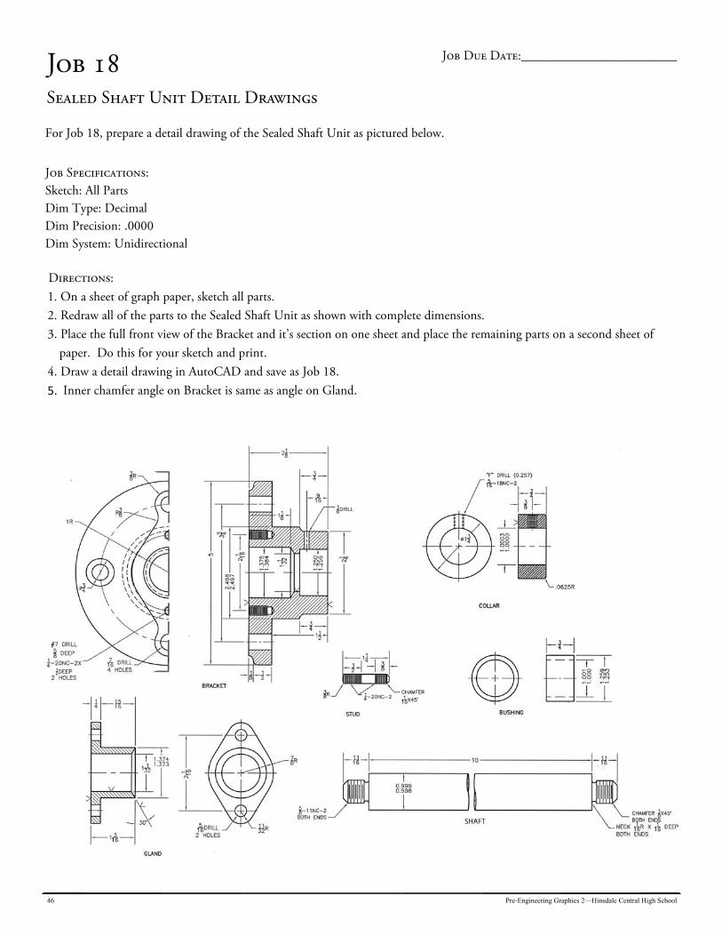
Job 18 Sealed Shaft Unit Detail Drawings
For Job 18, prepare a detail drawing of the Sealed Shaft Unit as pictured below.
Job Specifications: Sketch: All Parts Dim Type: Decimal Dim Precision: .0000 Dim System: Unidirectional Directions: 1. On a sheet of graph paper, sketch all parts. 2. Redraw all of the parts to the Sealed Shaft Unit as shown with complete dimensions. 3. Place the full front view of the Bracket and it’s section on one sheet and place the remaining parts on a second sheet of
paper. Do this for your sketch and print. 4. Draw a detail drawing in AutoCAD and save as Job 18. 5. Inner chamfer angle on Bracket is same as angle on Gland.
Job Due Date:________________________

Pre-Engineering Graphics 2—Hinsdale Central High School 47
Job 19 Sealed Shaft Unit Assembly Drawings
For Job 19, prepare an assembly drawing of the Sealed Shaft Unit.
On a sheet of graph paper, sketch all of the parts in an assembly drawing.
Job Specifications: Sketch: All Parts Dim Type: Decimal Dim Precision: .0000 Dim System: Unidirectional Directions: 1. On a sheet of graph paper, sketch all parts. 2. Redraw all of the parts to the Sealed Shaft Unit as shown with complete dimensions. 3. Place the full front view of the Bracket and it’s section on one sheet and place the remaining parts on a second sheet of
paper. 4. Draw a detail drawing in AutoCAD and save as Job 19. IMPORTANT MATERIAL NOTE: Bracket = Steel Gland = Steel Shaft = Steel Stud = Steel Collar = Steel Bushing = Brass
Job Due Date:________________________
48 Pre-Engineering Graphics 2—Hinsdale Central High School
Unit 8: Architectural Drawing: Chapter 24
Architectural drafting and mechanical drafting are similar in that both areas are designed to create pictures that convey information to someone else for the purpose of manufactur-ing. The skills and techniques acquired in Pre Engineering Graphics can certainly be applied to the study of architectural drafting. Both subject areas use the same tools and equipment to create graphic representation of those things we would like to create and build. One main difference in architecture is that the size of our product is much bigger. We have drawn things to sizes of 3-5 inches big. With architecture, we will be drawing things 20 to 30 feet long. The “scale” of our drawings will be much different. The common scale of drawing in architecture is 1/4” = 1’-0”. This scale reduces the home to a size that will fit on most drawing paper. Our ability to be accurate however is greatly reduced. Architects must also think and draw many different parts and design them to work together. Each part builds in turn on the next part. All architectural drawings are really “assembly” drawings. That is, the drawing shows how each part works with other parts to make a final assembly.
Common architectural sizes: Exterior walls 6 in. wide Interior walls 4.5 in. wide Hallways and staircases 3’0” wide Exterior doors 3’-0” x 6’-8” Interior doors 2’6” or 2’8”x 6’-8” Framing lumber 2”x4”, 2”x 6”, 2”x 8”, 2”x 10”, 2”x12” Plywood sheets, paneling 4’0”x 8’0” Plywood sheet thickness 1/4”, 3/8”, 1/2”, 5/8”, 3/4” Plumbing Walls 6 in. thick
Pre-Engineering Graphics 2—Hinsdale Central High School 49
50 Pre-Engineering Graphics 2—Hinsdale Central High School
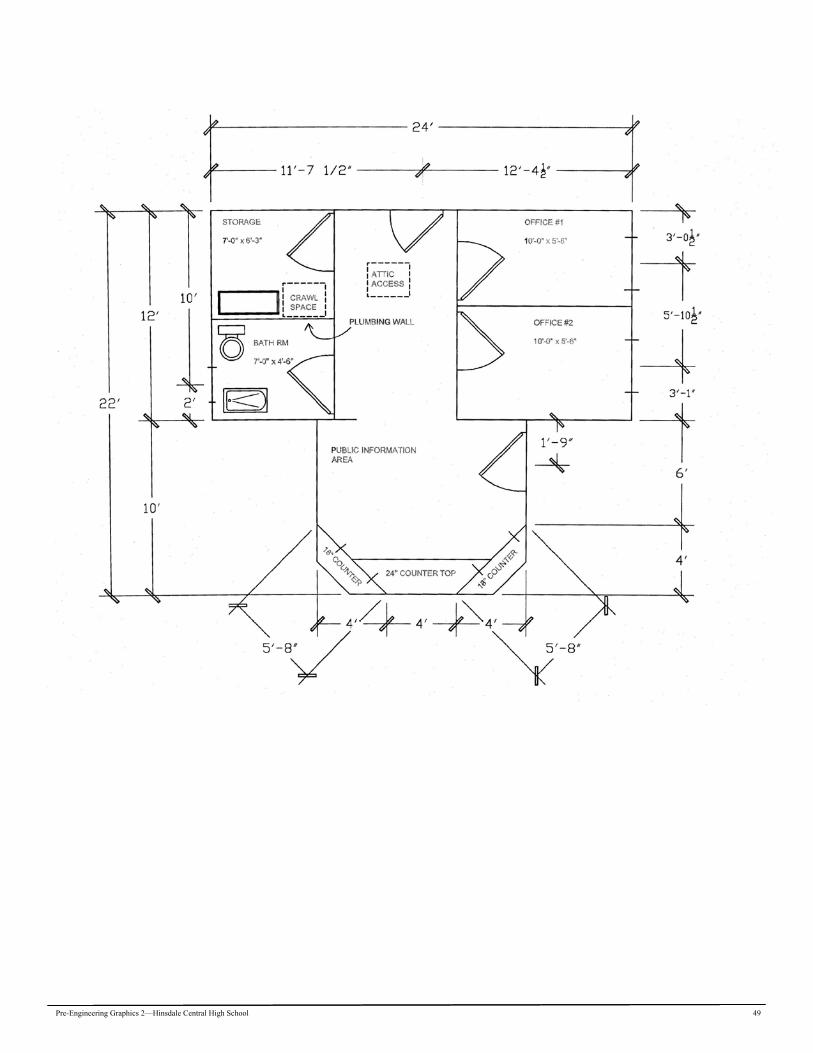
Job 20 Ranger Station Floor Plan
A sketch of an existing Forest Ranger Station is shown below. It has been determined that some of the existing dimensions need to be changed to provide more room. Sketch a revised copy on a sheet of graph paper to reflect the size changes out-lined below. Allow each square or grid to equal 1’-0”. Change: 1. The area which includes the 2 offices, bath, and storage area will increase in size from 24’-0”x 12’-0” to 24’-0”x 14’-0”. 2. The Public Information Area size from 12’-0” x 10’-0” to 12’-0” x 12’-0”. 3. Redesign the two offices, storage room, and the bathroom. Make each office the same size. Optional change: 1. You may choose to re-arrange the fixtures in the bathroom and storage area. 2. You may choose to re-locate office and bathroom window(s). Do not change: 1. The door sizes. a. Exterior doors are 3’-0” x 6’-8” b. Interior doors are 2’-8” x 6’-8” 2. The counter tops (inside and outside) 3. The attic access (scuttle hole) size, 3’-0” x 3’-0” 4. The crawl space access hole size, 3’-0” x 3’-0” CAD Drawing: 1. From your revised sketch, draw the floor plan on a new boarder designed for architectural drawings. 2. Dimension the problem the same as the sketch using architectural standards for dimensioning. 3. Label each area in text 6” high, and in Country Blueprint text font. 4. Space the dimensions about 1’-0” away from the building and each other. 5. Use the wall layer for only the walls. 6. Title: Forest Ranger Office in 8” high text. Job Specifications: Sketch: Yes Dim Type: Architectural Dim Precision: 1/2” Dim System: Unidirectional
Job Due Date:________________________
Pre-Engineering Graphics 2—Hinsdale Central High School 51
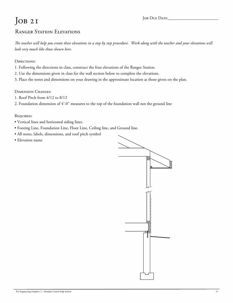
Job 21 Ranger Station Elevations
The teacher will help you create these elevations in a step by step procedure. Work along with the teacher and your elevations will look very much like those shown here. Directions: 1. Following the directions in class, construct the four elevations of the Ranger Station. 2. Use the dimensions given in class for the wall section below to complete the elevations. 3. Place the notes and dimensions on your drawing in the approximate location as those given on the plan. Dimension Changes: 1. Roof Pitch from 4/12 to 8/12 2. Foundation dimension of 4’-0” measures to the top of the foundation wall not the ground line Required: • Vertical lines and horizontal siding lines. • Footing Line, Foundation Line, Floor Line, Ceiling line, and Ground line. • All notes, labels, dimensions, and roof pitch symbol • Elevation name
Job Due Date:________________________
52 Pre-Engineering Graphics 2—Hinsdale Central High School
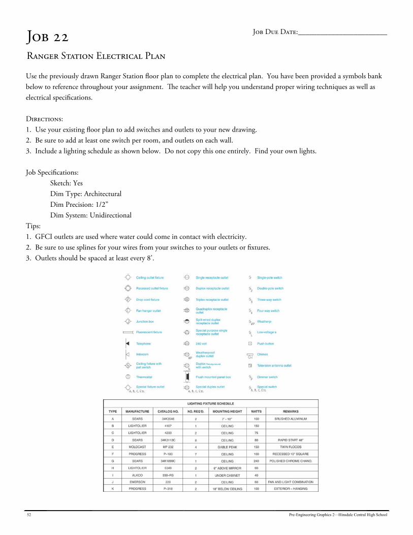
Job 22 Ranger Station Electrical Plan
Use the previously drawn Ranger Station floor plan to complete the electrical plan. You have been provided a symbols bank below to reference throughout your assignment. The teacher will help you understand proper wiring techniques as well as electrical specifications. Directions: 1. Use your existing floor plan to add switches and outlets to your new drawing. 2. Be sure to add at least one switch per room, and outlets on each wall. 3. Include a lighting schedule as shown below. Do not copy this one entirely. Find your own lights. Job Specifications: Sketch: Yes Dim Type: Architectural Dim Precision: 1/2” Dim System: Unidirectional Tips: 1. GFCI outlets are used where water could come in contact with electricity. 2. Be sure to use splines for your wires from your switches to your outlets or fixtures. 3. Outlets should be spaced at least every 8’.
Job Due Date:________________________

Pre-Engineering Graphics 2—Hinsdale Central High School 53
Job 23 Cover Page
Directions: Use the computer to design an attractive cover page for your drawing portfolio. The design is one of your choosing. Often, students take their logo and enlarge it so that it can serve as a good cover page design. Be as creative as you can be but you must include:
YOUR NAME NAME OF THE COURSE
DATE NOTE: After you have completed all the required work for the semester, arrange all of your work in numerical order. Any handouts, quizzes, or work exercises should also be saved and included in the booklet. Place these extra assignments in the appropriate section of your portfolio.
***If you need to print out any assignment again, there will be a .25 point reduction per sheet. ALL SHEETS IN YOUR PORTFOLIO MUST BE THE ORIGINAL COPIES WITH YOUR GRADES ON THEM. ***
Job Due Date:________________________