Embed Size (px)
Citation preview

PRE- FEASIBILITY REPORT (In terms of provision of EIA Notification 2006)
For
1 MTPA (2 X 0.51 million TPA) Ammonium Phosphate Fertilizer Plant
AT
Village - Biliya,
Tehsil - Chittaurgarh District- Chittorgarh
Rajasthan
By:
HINDUSTAN ZINC LIMITED,
Yashad Bhawan Udaipur - 313 004
Rajasthan
Submitted to:
Ministry of Environment, Forest and Climate Change
New Delhi
October 2016

2
TABLE OF CONTENT
Sr. No.
Chapter
Page No
1
Executive Summary
3
2
Introduction of Project
4
3
Project Description
5
4
Site Analysis
25
5
Planning
29
6
Rehabilitation and Resettlement (R&R) Plan
30
7
Project Schedule and Cost Estimates
30
8
Analysis of Proposal
30

3
1. Executive Summary
• Hindustan Zinc Limited (HZL) is Asia’s largest Non-Ferrous Metal producer of
Zinc and Lead, Head quartered in Udaipur, Rajasthan. HZL is world's second
largest integrated producer of with a global share of approximately 6.0% in
Zinc.
• HZL has its operations in exploration, mining, ore processing, smelting and
refining of Zinc & Lead. It is also a major producer of Sulphuric Acid, as a by-
product of Zinc-Lead Metal processing. HZL also has interest in Wind and
Thermal Power Generation.
• Zinc-Lead Ore beneficiation commenced at Zawar Near Udaipur in the year
1950 - under the name of ‘Metal Corporation of India (MCI). In the year 1966,
the Government of India took over the activities of MCI and Hindustan Zinc
Limited was formed. The Government of India has disinvested HZL in April
2002. HZL since 2002 is a Vedanta Group Company with 65% stake and 29%
stake with Govt. Of India and 6% with others.
• Hindustan Zinc has now proposed to set up an Ammonium Phosphate
Fertilizer Plant at Village - Biliya, Tehsil/District – Chittorgarh to have a
forward integration in product value chain by converting its own generated
Sulphuric acid & local rock phosphate available with RSMM.

4
2.0 INTRODUCTION OF PROJECT
2.1 Identification of Project and Project Proponent:
2.1.1 Identification of Project
Hindustan Zinc Limited operates a Primary Lead Zinc Smelter of production
capacity 0.525 Mtpa of Zinc, 0.85 Mtpa of Lead and 0.8 Mtpa of Sulphuric Acid
and CPP of 274 MW located at Chanderia near Chittorgarh, Rajasthan. The
proposed project is for installing a Di-ammonium Phosphate Fertilizer plant of
capacity 2 X 0.51 MTPA along with 2 X 0.24 Mtpa Phosphoric acid plant, 2 X 9000
TPA Aluminum Fluoride plant along with off sites & utilities facilities.
In this process, Sulphuric acid produced at Chanderia Lead Zinc Smelter shall be
converted to Phosphoric Acid and further to Di-ammonium Phosphate(DAP)
fertilizer/NPK/Ammonium Sulphate by granulation with Ammonia & Potash. The
project shall be installed at village Biliya adjacent to Chanderia Lead Zinc
Smelter. The bi-product Fluoro-Silicic Acid shall be converted to Aluminum
Fluoride & Gypsum shall be sold to local Cement producers.
2.1.2 Project Proponent
Hindustan Zinc Limited is among the largest producer of Zinc-Lead-Silver in India
and also a major producer of Sulphuric acid, with total metal production of over
1.14 Mtpa and Sulphuric Acid production of over 1.5 Mtpa. The Zinc Smelter at
Chanderia is operational since 1989 and has expanded from an initial capacity of
0.1 Mtpa to 0.525 Mtpa in 2009. It has a combined metal capacity of 0.625MTPA
HZL has secured agreement with RSMM (Rajasthan State Mines & Minerals) for
the supply of 4 lac MTPA rock phosphate concentrate ( 30% grade) and balance
shall be sourced from International market. The Sulphuric acid produced from
Chanderia Lead Zinc Smelter shall be converted to Phosphoric Acid and the
additional acid required shall be sourced from the HZL’s other Zinc smelter sites
in Rajasthan.
The Di-ammonium phosphate (DAP)/NPK/APS fertilizer will cater to domestic
market & thus reduce dependency on import market
2.2 Brief Description of nature of Project
It is proposed to install the following facilities:
TABLE-2.3
Project Facility Capacity Technology Purpose
Phosphoric Acid Plant (PAP)
2 x 240,000
TPA
Phosphoric
Acid
Hemi-
Dihydrate
Technology
(HDH)
To convert rock
phosphate by
reacting with
sulphuric acid
into marketable
product catering
to Fertilizer
Industry.
5
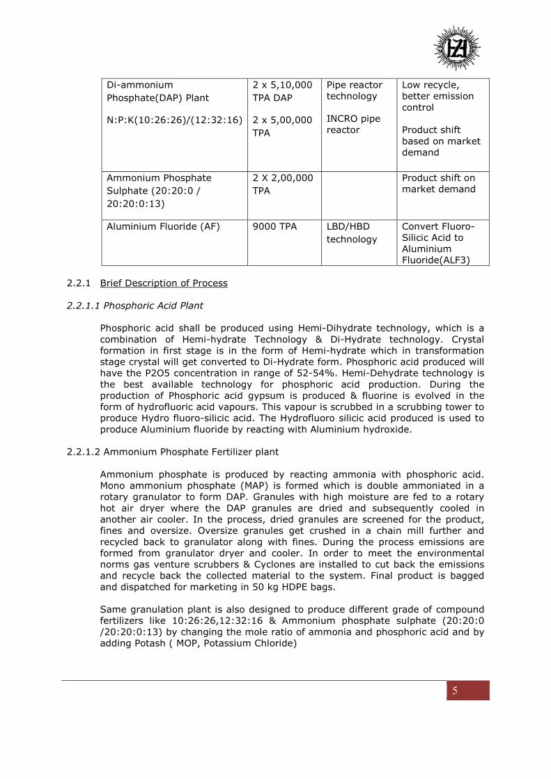
Di-ammonium
Phosphate(DAP) Plant
N:P:K(10:26:26)/(12:32:16)
2 x 5,10,000
TPA DAP
2 x 5,00,000
TPA
Pipe reactor
technology
INCRO pipe
reactor
Low recycle,
better emission
control
Product shift
based on market
demand
Ammonium Phosphate
Sulphate (20:20:0 /
20:20:0:13)
2 X 2,00,000
TPA
Product shift on
market demand
Aluminium Fluoride (AF) 9000 TPA LBD/HBD
technology
Convert Fluoro-
Silicic Acid to
Aluminium
Fluoride(ALF3)
2.2.1 Brief Description of Process
2.2.1.1 Phosphoric Acid Plant
Phosphoric acid shall be produced using Hemi-Dihydrate technology, which is a
combination of Hemi-hydrate Technology & Di-Hydrate technology. Crystal
formation in first stage is in the form of Hemi-hydrate which in transformation
stage crystal will get converted to Di-Hydrate form. Phosphoric acid produced will
have the P2O5 concentration in range of 52-54%. Hemi-Dehydrate technology is
the best available technology for phosphoric acid production. During the
production of Phosphoric acid gypsum is produced & fluorine is evolved in the
form of hydrofluoric acid vapours. This vapour is scrubbed in a scrubbing tower to
produce Hydro fluoro-silicic acid. The Hydrofluoro silicic acid produced is used to
produce Aluminium fluoride by reacting with Aluminium hydroxide.
2.2.1.2 Ammonium Phosphate Fertilizer plant
Ammonium phosphate is produced by reacting ammonia with phosphoric acid.
Mono ammonium phosphate (MAP) is formed which is double ammoniated in a
rotary granulator to form DAP. Granules with high moisture are fed to a rotary
hot air dryer where the DAP granules are dried and subsequently cooled in
another air cooler. In the process, dried granules are screened for the product,
fines and oversize. Oversize granules get crushed in a chain mill further and
recycled back to granulator along with fines. During the process emissions are
formed from granulator dryer and cooler. In order to meet the environmental
norms gas venture scrubbers & Cyclones are installed to cut back the emissions
and recycle back the collected material to the system. Final product is bagged
and dispatched for marketing in 50 kg HDPE bags.
Same granulation plant is also designed to produce different grade of compound
fertilizers like 10:26:26,12:32:16 & Ammonium phosphate sulphate (20:20:0
/20:20:0:13) by changing the mole ratio of ammonia and phosphoric acid and by
adding Potash ( MOP, Potassium Chloride)

6
The same facility shall be used to produce phosphate fertilizer products mix
namely DAP( Di-ammonium Phosphate) 18: 46: 0 ; APS (Ammonium Phosphate
Sulphate) 20: 20: 0 & 20: 20: 0: 13; NPK (12:32:16 / 10:26:26)
2.2.1.3 Aluminium Fluoride Plant.
During the process of Phosphoric acid production, fluorine gas evolves as hydrofluoric
acid fumes which get scrubbed with water to produce Hydro-fluorociclicic acid. Hydro-
flurosilicic acid is a feed sitcom for producing Aluminium fluoride by reacting with
Aluminium Hydroxide. The reaction shall produce silica which gets used back in
Phosphoric acid plant
2.3 Need for the Project and its Importance to the Country
2.3.1 Ammonium phosphate Fertilizer
DAP / NPK / APS are the most widely used phosphate fertilizer for agricultural
application which gives nitrogen, phosphorous & potash and micro nutrient
sulphur. Presently, India is importing over 5 Mtpa DAP/NPK as the current
capacity of the DAP/NPK production is limited due to the non availability of good
grade rock phosphate & sufficient sulphuric acid.
2.4 Demand & Supply Gap
As per Government of India, demand of domestic market for Phosphatic fertilizer
is 11 Million TPA and domestic production is only about 4 Million TPA.
2.5 Domestic Market
India is a net importer of DAP fertilizer. India’s current consumption of DAP/NPK
fertilizer is OVER 11 Million TPA. Rajasthan state has no DAP fertilizer
manufacturing facility at present. Current annual requirement of DAP is around
0.6 Million TPA.
2.6 Employment Generation
The proposed project will generate direct employment of approx 250 manpower
including contract labour. It will provide new opportunities for local people also
resulting in indirect employment for more than 1500 manpower. Training
programs will be set up for the development of local community as per the work
requirement.

7
3.0 PROJECT DESCRIPTION
3.1 Type of Project
The project is a category “A” type of project listed under item No.5a, Chemical
Fertilizer, in the Schedule of the EIA notification 2006.
3.1.1 Raw Material Sources
The primary raw materials for the proposed project are Sulphuric Acid, Rock
Phosphate, Ammonia, Potash. Sulphuric Acid produced in the Chanderiya Lead
Zinc Smelter shall be completely utilized and the short fall shall be sourced from
the other Zinc smelters of Hindustan Zinc Limited in Rajasthan.
Rock Phosphate requirement shall be sourced from RSMM and the shortfall shall
be resourced from international / domestic market.
Ammonia shall be imported from international & domestic market as well. All
imports shall be preferably through the Kandla / Dahej Port in Gujarat.
3.2 Location
Proposed project is proposed to set up at village Biliya, adjacent to our
Chanderiya Lead Zinc Smelter, located about 9 kms from Chitorgarh town.
Figure 3.1
LOCATION MAP OF THE PROJECT SITE

8
Figure- 3.2
DETAILED LAYOUT PLAN OF PROJECT
3.3 Alternate Sites Considered
HZL have considered and evaluated all its Smelters sites (Dariba, Chanderia,
Debari) for freezing the location. Chanderia site have been finalized due to
various supporting infrastructural and operational advantages.
Being close to the proximity of Chanderia Lead-Zinc smelter plant, this project
shall be provided with piped supply of Sulphuric acid, steam, power transmission
line along with water supply arrangement facility.
3.4 Size of Operation
Followings plants are proposed to be set up at Biliya, Chanderia:
TABLE-3.1
PLANT DETAILS
Project Title Capacity
Ammonium phosphate (DAP ) plant 2 x 5,10,000 TPA
Phosphoric Acid Plant 2 x 2,40,000 TPA Phosphoric Acid
N P K (10:26:26 /12:32:16) 2 x 5,00,000 TPA
Ammonium Phosphate Sulphate (APS
20:20:0 /:20:20:0:13:
2 x 2,00,000 TPA
Aluminum Fluoride 2 X 9000 TPA

9
Annual production capacities of proposed project is as follows along with their by-
product
TABLE-3.2
ANNUAL PRODUCTION CAPACITIES OF PROPOSED PROJECT
Type Particulars Capacity (TPA)
Products
Ammonium Phosphate(DAP, 18:46:0) 2 X 5,10,000
NPK(12:32:16 /10:26:26) 2 X 5,00,000
Ammonium Phosphate Sulphate, APS
(20:20:0 / 20:20:0:13)
2 X 2,00,000
Phosphoric acid 2 X 2,40,000*
Aluminium Fluoride 2 X 9,000*
By Product Hydro fluosilicic acid 2 X 9,100
Waste Gypsum 2 X 13,50,000
*Will be consumed within the process and surplus quantity shall be sold.
3.5 Project description with Process details:
Project description:
3.5.1 Phosphoric Acid Plant
Wet Phosphoric acid is produced by three main routes
- Hemi-hydrate Technology, In this process gypsum crystal formation will be in
form of Hemi-hydrate, Acid produced will be 43% grade phosphoric acid. Loss of
P2O5 will be more
- Di-Hydrate technology, this is most common process used in India for
manufacturing of Phosphoric acid. Gypsum crystal is in form of Di-hydrate which
is Phospho-Gypsum. Acid Produced will have the concentration from 26-30%
P2O5.
- Hemi-Dihydrate technology, This is the combination of both the process, Crystal
formation in first stage is in form of Hemi-hydrate and then in transformation
stage crystal will get converted to Di-Hydrate form. Phosphoric acid produced
will be pure and have the P2O5 concentration in range of 42-44%. This is most
efficient process
DH is widely used in India, HDH route is better due to following advantage over
other route
- Better P2O5 recovery
- Low steam consumption

10
- Production of 43% Phosphoric acid ex-Filter
- Better product & Gypsum quality
Hence HDH route is selected for Phosphoric acid production.
3.5.1.1 Details of Process Technology - Hemi-Dihydrate Technology
DH is widely used in India, however, Vedanta Group of company M/S Sterlite
industries Limited’s Phos acid plant is the only plant in India using HDH
technology for Phos acid production. HDH route is selected for Phos acid
production in the proposed project due to following advantage over other route
- Better P2O5 recovery
- Low steam consumption
- Production of 43% Phos acid
- Better product & gypsum quality
FIGURE–3.3-PROCESS FLOW CHART-HDH Process

11
3.5.1.2 PHOSPHORIC ACID PLANT - PROCESS DESCRIPTION
Phosphoric acid plant will consists of following sections
- Rock Phosphate unloading and storage
- Reactor section
- Hemi-Hydrate filtration section
- Transformation section
- Dehydrate filtration system
- Gypsum conveying and gypsum pond
- Clarification & Storage
- Evaporation section
3.5.1.2.1 HH Reaction Section
The design uses three reactors in series with low-sulphate zone and high-
sulphate zone. These reactors, of almost identical operating volume, are fitted
with modern agitators fabricated in duplex material resistant to corrosion and
erosion in the HH slurry. All the agitators of the HH reaction section will be fitted
with foam-breaking blades to reduce defoamer consumption. The design of the
launders and the differential heights between each of the tanks will be
considered so as to enable the foam produced to be tolerated more easily and
reduce the defoamer consumption.
Phosphate rock, from storage, is fed to the first reactor along with a controlled
slurry recycle flow from the high–sulphate reactor. Based on experience there
will be two horizontal centrifugal pumps, one spare, operating with variable
speed control providing the slurry recycle.
The slurry from the first reactor overflows to the second reactor which
complements the low-sulphate volume. This reactor is also fitted with a similar
agitator to the first reactor. There are no feeds to the second reactor.
The third reactor receives the sulphuric acid premixed with the return acid from
the HH filter in a special Zone and as such forms the high-sulphate zone of the
HH reaction section. The heat of reaction is removed by a low-level flash cooler
which re-circulates around this tank. The HH belt filter is also fed from this
reactor by the HH feed pumps.
The gases from the flash cooler go to the vacuum fluorine recovery section. The
dip pipe of the flash-cooler return is situated in an external chamber to prevent
interference with the agitator of the third reactor.

12
3.5.1.2.2 Flash-Cooler Vacuum Section
This section is a vacuum scrubber design having a droplet separation tower to
remove entrained acid carry-over but has a single stage scrubbing tower
operating batch-wise in an automatic programme improving the fluorine recover
efficiency.
The Fluorosilicic acid (FSA) seal tank is initially filled with water to the controlled
level and the recirculation pump started. Water is bled into the system to
maintain the level which decreases due to de-supersaturation of the vapors. As
time goes by the absorption of fluorine compounds increases the strength of the
FSA.
When the desired product strength, 20 – 22 % FSA, is reached the water valve
is closed and the export valve opened. This valve remains open until the level
reaches the low level alarm which closes the export valve and once again allows
the water inlet valve to control the level in the tank. Now the strength of the
circulating liquid is about 5% and the strength progressively increases once
again until the desired product strength is reached when the cycle repeats itself.
After the fluorine recovery section there is a pre-condenser to provide hot water
for filter washing without requiring the use of steam and this is followed by the
main condenser prior to the vacuum pump.
3.5.1.2.3 HH Off-Gas Scrubbing Section
The off-gas from the hemihydrate reactors even though having a relative small
volumetric flow contains relatively high fluorine content and the fluorine must
be removed before being directed to the stack to protect the environment.
This section consists of a first stage to remove entrained acid droplets that could
contaminate the fluosilicic acid (FSA). This first stage has a droplet separator
and a wet scrubber that operates with liquor saturated in FSA and the recovered
droplets with the FSA are returned to the HH reaction system. After the removal
of the acid droplets, the gases pass to two stages of venturi scrubbers. A
variable speed fan draws from the final void tower and the gases are combined
with those from the filtration off-gas section before passing through the main
exhaust fan to the stack Hemihydrate Filtration Section
This section consists of single horizontal belt filter having two counter-current
washes with the final wash being filtrate from the Dihydrate filter. This filter
13
discharges directly into a re-pulp tank the cake being re-slurried by filtrate from
the Dihydrate filter. Off-gas from the filter hood goes to the Filtration Off-gas
Scrubbing Section and fan. The gas joins the other streams from the filters and
the DH Off-gas scrubbers and proceeds to the tail- gas scrubber and stack via
the main exhaust fan.
Self-draining double outlet slurry feed boxes will be provided for the filter and
the wash box shall be of self-draining type with no pockets with integral dams
upstream to prevent mixing of washes. Downstream separately movable dams
will be provided for each box. Vacuum box divisions shall be liquid tight and
with variable positions, provision shall be made for the future addition of a
separator block in the vacuum box touching the belt to allow operation of the
vacuum box at two different vacuums. If implemented, this will enable a final
cake drying zone to be provided. The vacuum box shall be jacketed for hot
water heating if required.
Phosphoric acid from filtrate will be sent to storage/clarifier for 42% phosphoric
acid.
3.5.1.2.4 Hydration Section
This section consists of the two hydration tanks preceded by a re-pulp tank with
intensive agitation so as to fully disperse the HH cake in the re-pulping liquor.
This re-pulp tank also has an inlet for sulphuric acid either premixed with
hydration slurry or re-pulping liquor. Seed crystals from the second hydration
tank are recycled to the first hydration tank by a DH slurry recycle pump. The
first tank will be maintained in depression by the off-gas fan which creates a air-
flow to be able to maintain the temperature of the hydrating slurry below 65°C.
Two new DH filter feed pumps feed the DH filter with two washes and a final
dedicated cake drying section. Off-gas goes to the DH Off-gas Scrubber.
3.5.1.2.5 Dihydrate Filtration Section
This section consists of a single belt filter, fitted with two counter-current
washes and a polishing wash. Hot water from the precondenser is used for the
cloth wash and subsequently for final cake wash. The filtrates are returned to
the hemihydrates filtration section as wash-water and also for sluicing the
discharged hemihydrates cake in the repulp tank. Off-gas from the filter hood
goes to the DH Off-gas Scrubber. A split vacuum box enabling the final cake
drying section to be independent will be used which uses two separate vacuum

14
systems on the filter ensuring minimum moisture in the discharged dihydrate
cake.
3.5.1.2.6 Filtration Off-Gas Scrubbing Section
This section consists of a multi-stage venturi scrubber system with intermediate
void cyclonic towers these gases combine with those of the HH Off-gas
Scrubbing system and the HH filter prior to being routed to the stack via the
main exhaust fan.
3.5.1.2.7 Evaporation Units and Fluorine Recovery
The evaporation section of the Phosphoric Acid Plant, considering single-stage
vacuum evaporators, with carbon tube heat exchangers, is designed to raise the
concentration from 43 % P2O5 to 52-54 % P2O5.
The design consists of a single-stage vacuum evaporators with forced circulation
using a graphite tube heat exchanger, an axial-flow pump and a flash chamber.
The recirculation loop is connected to the base of the flash chamber which is
fitted with a vortex breaker to prevent cavitation of the axial-flow pump.
Low pressure steam is received from the Battery Limits and the evaporative
capacity of the unit is defined by the flow controller on the steam feed.
The level in the flash chamber is controlled by an overflow at such a height that
the boiling of the heated acid prior to entering the flash chamber is prevented.
Weak acid is received from storage/clarifier 42% phosphoric acid and fed into
the acid flow leaving the heat exchanger. The concentrated acid drains via the
standpipe overflow to the agitated product acid seal tank and is pumped to
storage/clarifier 52% phosphoric acid by the concentrated acid pump.
Flurosilicic acid (FSA) is produced in the fluorine recovery section which is a
concurrent absorption tower operating batch wise to improve recovery. The
flashed vapours containing mainly water and fluorine compounds pass through a
high efficiency droplet separator prior to entering the fluorine recovery section.
The acid droplets will report back to the flash chamber. Product is drawn off by
a self regulating variable speed pump and delivered to the storage area.
The residual water vapour, almost free of fluorine compounds, passes through a
direct contact condenser fed with cooling water. The condenser water is
collected in a barometric seal tank which overflows to the return trench and
returned by gravity to the cooling tower.

15
FIGURE-3.4
Process Flowchart for Fluoro-Silicic Acid
FIGURE-3.5
Hemihydrate Filtration

16
FIGURE-3.6
Dihydrate Filtration
FIGURE-3.7
Evaporation

17
3.5.2 PROCESS DESCRIPTION FOR AMMONIUM PHOSPHATE PLANT
Design Basis:
Plant capacity: 5, 10,000 MTPA
Operating days: 330 days per annum
Capacity: 1550 MTPD of Ammonium Phosphate Fertilizer (DAP/NPK/APS)
Operating Hours: 22 hours per day
Hourly capacity: 70 MTPH
Major raw materials: Phosphoric acid, Sulphuric acid, Ammonia, Potash, Filler
Emission level of APF Plant:
Dust: 50 mg / Nm3
Fluorine: 10 mg / Nm3
Ammonia: 5 mg/Nm3
Treated effluent Discharge: Zero
Acid preparation section:
Fresh phosphoric acid is sent to Scrubber Circulation Tank. The Scrubber Pumps send
the scrubber liquor to the Granulator and Drier Scrubber. In the Granulator Scrubber
the acid fixes most of ammonia lost from the Granulator. The scrubber liquor results
partially neutralized and falls by gravity into the Scrubber Circulation Tank. In the Drier

18
Scrubber the acid fixes the ammonia evolved in the Drier and also dissolves the dust of
DAP entrained from the Drier Cyclones. The acid falls by gravity to the Scrubber
Circulation Tank where it is mixed with the acid coming from the Granulator Scrubber.
Pipe reaction & Granulation
From the Scrubber Circulation Tank, the partially neutralized Phosphoric Acid enters the
Pipe Reactor where the acid reacts with ammonia under pressure to a final molar ratio of
2.0 No need for further ammonia addition in the Granulator Bed is required.
The reactions are instantaneous and exothermic and the reaction heat is used to
evaporate part of the water of the phosphoric acid fed to the Plant. This water vapour
and the unreacted ammonia are fed to a stream of air flowing through the Granulator
and are sent to Granulator Scrubber. The APF melt produced in the reactor is sprayed
over the bed of recycle and by temperature effect and moisture it becomes granulated.
To prevent the build up of solids the Granulator walls are lined with selfcleaning rubber
panels that also minimize heat losses.
Solid Handling:
The granulated APF falls into the rotary Drier where it dries in contact With a co-current
flow of hot air coming from the Drier Burner. Product leaving the Drier is sent, through
the Ex-Drier Elevator, to the top of the Screens, where is divided into three streams: the
oversize, the onsize and the fines. The oversize (and some on-size if required) passes
into the Oversize Pulverizers. Crushed materials, fines and the dust collected by the
Drier Cyclones, FBC Bag Filter, and Dedust Bag Filter, are discharged on the Recycle
Conveyor. The on-size product from the Screens falls into a Fluidized Bed Cooler where it
is cooled to the desired temperature. Finally, the product is sent to the storage.
Utilities consumption (per MT of APF)
Electricity 45 kWh
Fuel oil 04 Kg
PROCESS FLOW DIAGRAM: Fig 3.9
19
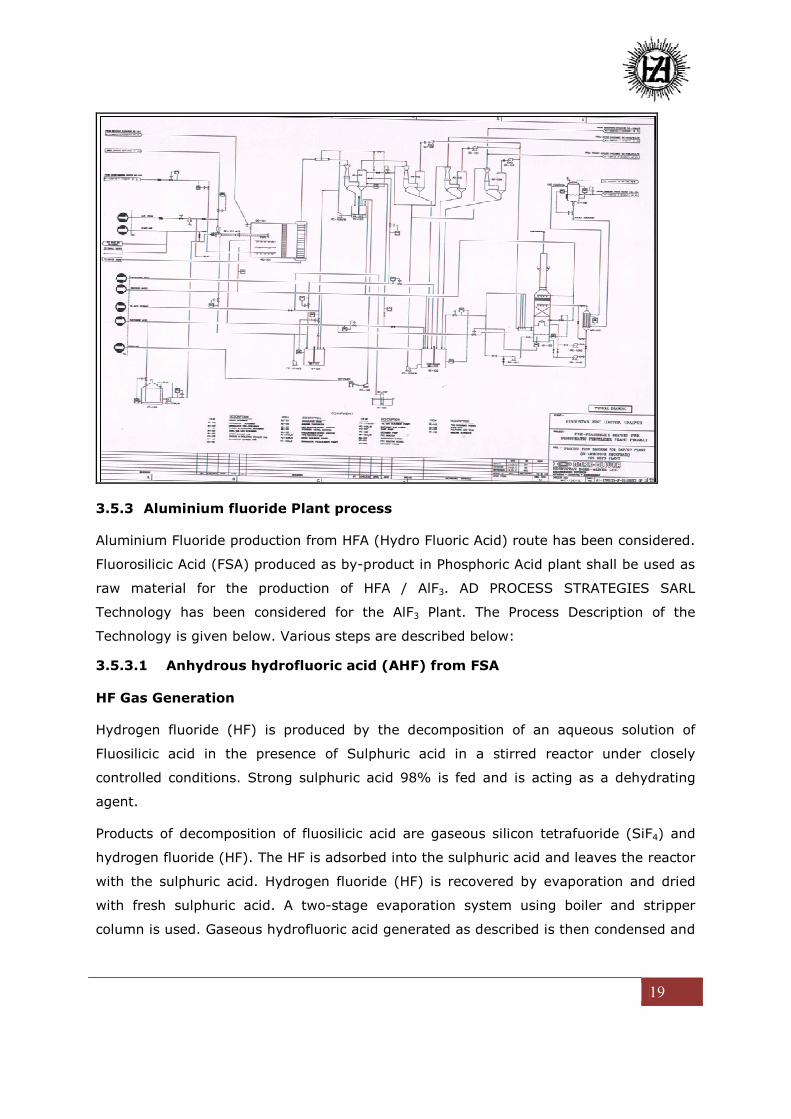
3.5.3 Aluminium fluoride Plant process
Aluminium Fluoride production from HFA (Hydro Fluoric Acid) route has been considered.
Fluorosilicic Acid (FSA) produced as by-product in Phosphoric Acid plant shall be used as
raw material for the production of HFA / AlF3. AD PROCESS STRATEGIES SARL
Technology has been considered for the AlF3 Plant. The Process Description of the
Technology is given below. Various steps are described below:
3.5.3.1 Anhydrous hydrofluoric acid (AHF) from FSA
HF Gas Generation
Hydrogen fluoride (HF) is produced by the decomposition of an aqueous solution of
Fluosilicic acid in the presence of Sulphuric acid in a stirred reactor under closely
controlled conditions. Strong sulphuric acid 98% is fed and is acting as a dehydrating
agent.
Products of decomposition of fluosilicic acid are gaseous silicon tetrafuoride (SiF4) and
hydrogen fluoride (HF). The HF is adsorbed into the sulphuric acid and leaves the reactor
with the sulphuric acid. Hydrogen fluoride (HF) is recovered by evaporation and dried
with fresh sulphuric acid. A two-stage evaporation system using boiler and stripper
column is used. Gaseous hydrofluoric acid generated as described is then condensed and

20
purified by distillation to obtain the desired product quality and finally is sent to the
intermediate AHF Storage Tank.
H2SiF6.SiF4 (aq.) + H2SO4 = 2 SiF4 + 2 HF (aq.) + H2SO4 (aq.)
Next the Silicon Tetrafluoride (SiF4) gas leaving the reactor after drying column is
absorbed into the Fluosilicic acid (H2SiF6) feed solution to generate additional acid and
silica according to the chemical reaction:
5 SiF4 + 2 H2O = 2 H2SiF6.SiF4 (aq.) + SiO2 (hydrate)
The strong solution of fluosilicic acid is sent to the silicon tetrafluoride reactor.
The diluted sulphuric acid stream obtained after stripper is cooled down prior storage
and recirculation to the phosphoric acid plant.
Flow Sheet Showing Production of AHF from FSA
AHF Liquefaction and Purification
The crude HF gas is sent the purifying column. From this column the gases pass to two
condensers in series, where the bulk of the hydrofluoric acid is liquefied using chilled
water of controlled temperature.
Condensed hydrofluoric acid from the first condenser is send back as reflux to the top of
the purifying column. From the second condenser the partially purified hydrofluoric acid
is fed to a pressurised rectifying column, where light impurities, mainly sulphur dioxide
and silicon tetrafluoride, are removed as overhead stream. The pure hydrofluoric acid
leaves the rectifying column via the distilled acid cooler to AHF storage tank, using the
pressure of the rectifying column as the driving force. The gaseous overhead products
stream from the rectifying column and second HF condenser are passed through a

21
packed H2SO4 absorption column, down which sulphuric acid is circulated to absorb
most of the remaining hydrofluoric acid. A stream containing hydrofluoric acid in
sulphuric acid is then pumped back. Gases leaving the H2SO4 absorption column are
contacted with water in two ejector scrubbers in series. These remove silicon
tetrafluoride as fluosilicic acid. This stream is re-circulated.
Water effluent sent to the neutralisation is adjusted to minimize the losses of fluorine
and decrease the costs of treatment. Tail gases leaving these scrubbers via the tail gas
exhaust fan are given a final cleaning in the central absorption scrubber washed with
water before emission to atmosphere.
AHF Storage
HF sub-cooled is stored under atmospheric pressure in tanks installed inside a larger
containment tank. The heat losses are minimized by drying the air inside the
containment tank. The air is monitored continuously to detect any leaks of HF. A back-
up chiller is provided on emergency power. The system is corrosion free after 20 years
operation.
The product AHF delivered by Containers flows under pressure via the AHF Circulation
Cooler to the AHF Storage Tanks.
The main storage system comprises of AHF Storage Tank(s), T-421 A/B/C, within the
AHF Storage Containment Tank, T-422. The stored acid is re-circulated through the AHF
Circulating Cooler, E-420 and can be cooled down to say +5 to -8 °C according to
coolant.
The combination of storing AHF acid at low temperature within a double skin system
offers maximum safe storage of this dangerous chemical.
The storage system is equipped with adequate pressure control and safety
instrumentation. The gas from the inside of the outer containment is being continuously
dried and sampled for HF. A cabinet including a detector for fluorine is included.
Hardwired level switch is provided to trip in case of high high alarm all feeds of fluorspar,
acid, oleum, acid recycling and any pump that could fill the tanks with AHF.
Double bottom valves welded are provided on each tank for maximum safety. Manual
operated is making the system more simple and more safe to operate.

22
3.5.3.2 High-bulk-density Aluminium Fluoride (HBD AlF3) from HF
The Alumina hydrate is stored into the “Day-Shift” Silo (Hydrate Silo). The Hydrate is
discharged batchwise from the Silo by operating the Discharge Screw (Hydrate Silo
Discharge Screw) for feeding the Hydrate Feed Bin.
The Discharge Screw is controlled by switches onto the Hydrate Feed Bin which is
suspended on two Load cells and switch onto the Hydrate Distributor Bin. The Hydrate is
then fed batchwise from the Hydrate Feed bin to the Hydrate Distributor Bin where a
level of hydrate is maintained which acts as a vacuum seal and keeps the vacuum in the
system.
The load cells are used to totalize the alumina fed to the Aluminium Fluoride Reactor. It
is furthermore indicating exactly the capacity of the Aluminium Fluoride Reactor.
The alumina tri-hydrate is fed continuously to the Reactor via two Feed Screws.
Flow sheet Showing Production of AlF3 from AHF
First Hydrate Feed Screw is feeding most of the material and is controlling the
temperature in the top bed. The speed of the Hydrate Feed Screw is adjusted according
to the temperature in the bottom bed and top bed.

23
The Feed Screw is feeding the material via a fluidisation cup and this for avoiding the
agglomeration of hydrate especially at start-up.
Hydrate Bottom Feed Screw feeds the bottom bed at a small feed rate for diluting the
bottom bed and for obtaining a lower grade for the aluminium fluoride product. This is
controlled manually by setting the speed of this screw manually.
The reaction can be represented by the following equations:
Al2O3.3H2O = Al2O3 + 3 H2O
Al2O3 + 6 HF = 2 AlF3 + 3 H2O
Since the overall reaction is exothermic, the AlF3 Reactor does not need supplementary
heat during normal operation. During start-up it does need to be preheated using the
Combustion Chamber. This item is also used for keeping warm the aluminium fluoride
Reactor if the feed of HF gas is interrupted. Solids carried out of the Reactor are
recovered by cyclone separators. Under rated capacity, the dust collected in cyclone 1 is
not re-circulated to the Aluminium Fluoride Reactor. Only under high load or if the
quality needs to be improved dusts are re-circulated to the aluminium fluoride reactor
preferably to the top bed if the grade has to be increased and preferably to the bottom
bed if both the grade has to be improved and the content of silica to be reduced
significantly. Whether or not dusts are re-circulated to the Aluminium Fluoride Reactor,
the discharge of dusts from Cyclone directly to product into the Aluminium Fluoride
Cooler, is always operated.
Vacuum is kept at discharges of cyclones by level maintained in Cyclone Bin installed
underneath and equipped with discharge device and valve.
The aluminium fluoride is discharged from the bottom bed of the Aluminium Fluoride
Reactor through the discharge and then cooled down into a fluidised bed cooler to a
temperature preferably lower than 80°C.
The Off-gases from aluminium fluoride reactor after Cyclones are quenched and
condensed in the absorber and then are scrubbed.
The condensation of HF, H2O, etc occurs in the Absorber and HF Scrubber without
addition of water. The concentration of fluorine in the liquor formed provides a good
indication of the efficiency of the reactor and is used for its control.
The diluted acid solution produced will be sent to the neutralization plant or reused.

24
The second column is used to remove the traces of Fluorine, S, dusts, etc. This column is
the stand-by unit for the third column in case of fouling and vice versa.
The fluidisation in the Aluminium Fluoride Reactor is maintained by the vacuum obtained
from the operation of a Steam Ejector.
An Absorption System common to the aluminium fluoride plant and hydrofluoric acid is
provided.
Water is sent to the final absorber in order to absorb totally HF and reach the emission
limit for F in the off-gases in all modes of operation of the plant. This effluent water is
also sent to the neutralization plant or reused.
3.6 Raw Material Requirement
TABLE-3.3
DETAILS OF RAW MATERIAL
Plant Capacity Raw Material
(major)
Source Marketing
area of
finished
product
Mode of
transport
Phosphoric
Acid Plant
2 x 2,40,000
TPA
Phosphoric
Acid
Rock
phosphate:
2 X 7,90,000
TPA
Domestic/
import
Own
consumption
in DAP /NPK
Domestic
Pipeline/
Road
Sulphuric Acid
2 X 7,20,000
TPA
Own
Smelters
Ammonium
Phosphate
Plant
2 X5,10,000
TPA
Ammonium
phosphate
Phosphoric
acid:2 X
2,40,000
TPA
Captive
Domestic
market
Rail / Road
Ammonia: 2 X
1,20,000 TPA
Import
Potash: 2 X
1,50,000 TPA
Import
Aluminium
Fluoride
2 X 9000 TPA Fluoro-Silicic
Acid
2 X 9100 TPA
Aluminium
Hydroxide 2 X
9100 TPA
By-product
from
Phosphoric
Acid Plant
Domestic
market
Road
3.7 Resource optimization/ recycling and reuse
The presence of Fluoride in Rock Phosphate will be recovered as a value product
of Aluminium Fluoride and Fluoro Silicic Acid. Phospho Gypsum generated as a

25
waste shall be utilized in Cement Industries. The waste water generated from the
proposed project shall by treated through appropriate recycling and reuse.
3.8 Water & Power Availability & Source
3.8.1 Water Availability
HZL has approvals for withdrawal of water from the Ghosunda dam and the same
shall be used for the proposed project. The water from these sources shall be
appropriately treated to improve the quality to suit the requirement of the
proposed project.
Chttorgarh town is also in the final stage of commissioning of its 1st kind STP
plant of 10 KLD which is also being discussed with for 100% utilization at the
plant
3.8.2 Power Availability
A total power requirement of 17 MW for the proposed projects shall be sourced
from the state grid through the Ajmer Vidyut Vitaran Nigam Limited (AVVNL),
Rajasthan
Emergency Power Generation
In addition to the existing emergency backup power source, the following Diesel
Generator (DG) sets have been proposed for the proposed project.
1) 2 no x 2500 KVA emergency DG
3.9 Wastewater Generation and its Management
The total effluent generations from the project is are as given below;
TABLE-3.4
EFFLUENT GENERATIONS FROM THE PROJECT
S. No. Plant Effluent generation (cum/h)
1 Phosphoric Acid Plant 2 X 100
2 Fertilizer Plant 0
3. Aluminium fluoride plant 2 X 100
Total 2 X 200
The effluent generated from phosphoric acid plant will be treated to remove
fluoride and will be treated to neutralize the acidity.
Effluent Treatment Plant shall be installed to treat the effluents generated from
the proposed project and other associated services to a reusable quality and
completely reused to maintain a zero discharge operation.

26
Sewage Treatment Plant shall also be installed to treat the domestic effluent
generated. Treated water shall be utilized for plantation and other uses.
4.0 SITE ANALYSIS
4.1 Connectivity
Project location is on the well connected with National highway NH-79 at
(distance 5.0 kms). The nearest Railway head is at Chanderia Station, about 2.5
kms on Chittorgarh- Delhi Route.
4.2 Land Form, Land use and land ownership
4.2.1 Land Form
The proposed land terrain is flat and developed.
4.2.2 Land Use
The proposed project site is an industrial land.
4.2.3 Land Ownership
Total Land for the proposed project site is owned by Hindustan Zinc limited.
4.3 Topography
Topography of the project site 10 kms radius is shown in the map below

27
TOPOGRAPHICAL FEATURES OF THE AREA
4.4 Existing Land Use Pattern
The total available area at village Biliya is 105.05 Ha. This area is classified under
Industrially Developed Area (IDA). The details are as given below:
Land use pattern Land use *Details (Hectare)
Process & Ind. building IDA -
HW disposal facility IDA -
Green belt -

28
Open area 105
Total 105
4.5 Existing Infrastructure and Amenities
The following infrastructure exists:
- Metal top road connecting to the nearest NH-76 (0.5 Km) away.
- Well connected internal roads and internal electrical lines
- 132 kV Electrical Substation Township and guest house facility
- Hospital
- Drinking water facility
- Recreational facility with well developed township
- Post office, Bus station, Railway station, Banks, shopping complex,
community halls, Sr.Sec schools, worship places etc, exists.
The existing infrastructure shall be upgraded to cater to the requirements of the
proposed project where ever necessary.
4.6 Soil Classification
The texture of soil is mostly clayey in the buffer area. The common color of the
soil ranged from brown to brownish black.
4.7 Climatic data and secondary sources
The details on climatic data from primary and secondary sources are as given in
following table:
TABLE-4.1
Particulars Details
Location Village - Biliya, Chittorgarh
Project Area Coordinates
Latitude Range 24°58’00” N to 24°58’30” N
Longitude Range 740 39’ 50” E to 740 40’ 20” E
Geographical Location in Toposheet
Elevation above Mean Sea Level 392 m
Climatic Conditions as per IMD- Chittorgarh(Dabok)
a. Temperature Maximum- 42.30C, Minimum- 2.70C
b. Relative Humidity Maximum- 85% , Minimum.- 24%
c. Wind Speed Range 2.6 to 11.7 Kmph
d. Annual Rainfall 650 mm (average)
e. Predominant wind direction N and NW

29
Particulars Details
Nearest Highway • NH-79 (5 km)
• NH-76 (5 km)
Nearest Railhead Chanderiya (3.0 km, SW)
Nearest Railway Line Udaipur – Delhi line (2 kms)
Nearest Airport Maharana Pratap Airport – Udaipur 110
km
Other Historical / Religious Places Chittorgarh Fort (6.5 km, SSW)
Defense Installations Nil
Ecologically sensitive areas /
protected areas as per Wildlife
Protection Act 1972 (National Parks
/ Wild life sanctuaries / bio-sphere
reserves / tiger reserves)
No National Park.
Bassi wildlife sanctuary is more than 10
km from the plant
Reserved / Protected Forest • RF near Chanderiya Village (3.8
km, SW)
• RF near Bhiliya khera Village (3.3
km, E)
• RF near Gwalaji ka khera (5 km,
WNW)
• RF Chittorgarh Fort (8.0 km, S)
• RF Era (9 Km, NW)
Nearest Village Biliya - 1 kms
Nearest Town/City and Tourist
place
Chittorgarh (9.0 km SSW), population of
1,16,530 (2011 census)
Hills / Valleys Low altitude hills on the SE site of the
project site.
List of Industries • Hindustan Zinc Ltd., Chanderiya
lead & Zinc Smelter (Adjacent)
• Birla Cement works (2.5 km, SSW)
• Marble processing units (4.6 km
SSW & 0.5 Km N)
Seismicity Zone-II (IS 1893 Part-I:2002)

30
4.8 Social Infrastructure available
The existing infrastructure in the project site includes the following
• 16 bed hospital with ambulance
• Bank
• Post Office
• Fire Station
• Senior Secondary School
• Police Station
• Shopping Complex
• Sports Infrastructure (Stadium & Camps etc)
• Self Help Groups
• Community Halls
• Primary Health Care Centers
5.0 PLANNING
5.1 Planning Concept
The area comes under the village Biliya and the city limits of Chittorgarh starts at
a distance of about 9 kms from the project site. There are many educational
institutes, medical and hospital facility, industrial area, markets developed within
the 10 Km radius. The airport is located at a distance of 110 kms form the project
site. The proposed site is well connected by basic infrastructures like rail, road,
electricity and water, maintained by Govt of Rajasthan.
5.2 Population Projection
Population
The population of the village Biliya as per census 2011 is 1475.
5.3 Land Use planning
The entire 105.05 Ha. of the property is an industrial land use. The land falls in
the villages of Biliya Gram Panchayat.
No additional land is proposed to be acquired for the project.
5.4 Assessment of Infrastructure demand (Physical and social)
For the proposed project there shall be demand for the following physical and
social infrastructure.
i) Railway Network – Railway siding within the project area will be
developed.
ii) Water Supply-the existing infrastructure will be upgraded from Gosunda
dam & Chittorgarh STP.

31
iii) Power transmission – New transmission line will be laid out from existing
substation / switch yard through Rajasthan State Electricity Board
iv) Housing – Existing Township will be upgraded to partly accommodate the
additional manpower and the remaining will be catered by the adequate
infrastructure existing in the city of Chittorgarh.
5.5 Amenities and Facilities
i) Education: There exists a primary and secondary school within the
township. Additionally numerous education facility is available in the city
of Chittorgarh.
ii) Social Infrastructure like Post Office, Bank, Police Station, Bus Station,
Facility Exists and will continue to meet the demand of increased
populace.
iii) Telecommunication, LPG services, Marketing stalls, Sports infrastructure –
exists and shall continue to meet the demand of increased populace.
iv) Recreation- City of Chittorgarh offers adequate recreational facilities.
v) Hospital – existing 16 Beds hospital with ambulance that would be
adequate. There are many hospitals within 5-10 kms distance from the
project site.
vi) Commuting/conveyance- Conveyance system from project site to the
nearby towns and city is adequately developed.
vii) Waste water treatment – the existing sewage treatment facility in the
township shall be upgraded to meet the increased demand.
viii) Municipal Solid waste management – The present infrastructure will be
strengthened.
6.0 REHABILITATION AND RESETTLEMENT (R&R) PLAN
The Entire land required for the project is registered in the name of Hindustan
Zinc limited and does not have any settlement. So there shall be no
Rehabilitation & Resettlement (R&R).
7.0 PROJECT SCHEDULE AND COST ESTIMATES
7.1 Project Schedule
The entire project shall be implemented within 24 months from the date of grant
of Environment clearance
7.2 Capital Cost Estimates
The capital cost of the project is estimated at Rs. 1200 Crore with a payback of
about 6 years.
7.2.1 Expenditure on Environment in Project Cost
The overall cost on measures for the environment protection will be about 3 % of
the total project cost. The cost will include the Pollution prevention and control
measures, Land fill site construction cost, setting up of emission control and

32
environmental monitoring equipments and stations and development of the green
cover as per the statutory.
8.0 ANALYSIS OF PROPOSAL
8.1 Financial Benefit
The proposed project shall generate reduce import of Fertilizer thus saving of
foreign exchange. This will also generate revenue to the state Government as
well as central government. The people around the region will get direct and
indirect employment thus improves the financial status.
8.2 Social Benefits
The proposed project shall further strengthen its committments on CSR
investment for overall upliftment of socio economic index of the communities
around the project site by way of financial and administrative support. The
project will open up large employment opportunities, directly and also indirectly.
There shall be opportunities for entrepreneurs to engage in many service sectors
directly or indirectly associated with the project.
The CSR approach of the company shall be towards sustainable livelihood
management of the community around. There shall be focus on education,
health, sanitation, drinking water, agriculture, water shed management, culture
identity preservation, welfare of socially weaker sections and marginalized
people.
-----------------------