Embed Size (px)
Citation preview
INFRASTRUCTURE SERVICES
STANDARDS FOR ROAD CONSTRUCTION
CONSENT AND ADOPTION
SPECIFICATION
Issue B – 12th February 2015
TABLE OF CONTENTS
PREAMBLE TO THE SPECIFICATION .................................................................................................. 4
ADDITIONAL CLAUSE 970 - PRECAST CONCRETE BLOCK PAVING .............................................. 5
APPENDIX 0/3: LIST OF NUMBERED APPENDICES REFERRED TO IN THE SPECIFICATION .. 6
APPENDIX 0/4: LIST OF DRAWINGS INCLUDED IN THE STANDARDS ...................................... 8
APPENDIX 1/5: TESTING TO BE CARRIED OUT BY THE DEVELOPER ..................................... 10
APPENDIX 1/6: SUPPLY AND DELIVERY OF SAMPLES TO THE ROADS DEVELOPMENT
ENGINEER .............................................................................................................. 26
APPENDIX 4/2: PEDESTRIAN GUARDRAILS ................................................................................ 27
APPENDIX 5/1: DRAINAGE REQUIREMENTS ............................................................................... 28
APPENDIX 5/2: SERVICE DUCT REQUIREMENTS ....................................................................... 29
APPENDIX 5/5: COMBINED DRAINAGE AND KERB SYSTEMS .................................................. 31
APPENDIX 5/6: LINEAR DRAINAGE CHANNEL SYSTEMS ......................................................... 31
APPENDIX 6/1: REQUIREMENT FOR ACCEPTABILITY OF TESTING ETC. OF EARTHWORKS
MATERIALS ........................................................................................................... 32
APPENDIX 6/5: GEOTEXTILES USED TO SEPARATE EARTHWORKS MATERIALS................. 32
APPENDIX 6/7: SUB-FORMATION AND CAPPING AND PREPARATION AND SURFACE
TREATMENT OF FORMATION............................................................................. 33
APPENDIX 6/8: TOPSOILING .......................................................................................................... 33
APPENDIX 6/9: EARTHWORKS, ENVIRONMENTAL BUNDS, LANDSCAPE AREAS,
STRENGTHEND EMBANKMENTS ....................................................................... 33
APPENDIX 7/1 PERMITTED PAVEMENT OPTIONS ..................................................................... 34
APPENDIX 7/2: EXCAVATION, REPAIR AND REINSTATEMENT OF EXISTING SURFACES ... 36
APPENDIX 7/70: PREPARATION FOR SURFACING AND ADJUSTMENT OF IRONWORK ......... 36
APPENDIX 11/1: KERBS, FOOTWAYS AND PAVED AREAS ......................................................... 38
APPENDIX 11/1 – A: FOOTWAYS AND PAVED AREAS (PRECAST CONCRETE PAVING) .......... 38
APPENDIX 11/1 – B: FOOTWAYS AND PAVED AREAS (FLEXIBLE CONSTRUCTION) .............. 39
APPENDIX 11/1 - C: FOOTWAYS AND PAVED AREAS (INSITU CONCRETE PAVING) .............. 41
APPENDIX 11/1 - D: FOOTWAYS AND PAVED AREAS (CONCRETE BLOCK PAVING) .............. 42
APPENDIX 11/1 - E: FOOTWAYS AND PAVED AREAS (GRANOLITHIC CONCRETE PAVING) . 43
APPENDIX 11/1 - F: FOOTWAYS AND PAVED AREAS (GRANITE SETT PAVING) .................... 44
APPENDIX 11/1 - G: FOOTWAYS AND PAVED AREAS (STONE SLABBED PAVING) ............. 45
APPENDIX 11/73: FOOTWAYS AND PAVED AREAS (RACKING OF EXISTING KERBS, SETTS
AND SLABS)........................................................................................................... 45
APPENDIX 12/1: TRAFFIC SIGNS - GENERAL REQUIREMENT FOR TRAFFIC SIGNS ................ 46
APPENDIX 12/3: ROAD MARKINGS ................................................................................................. 49
APPENDIX 13/1: ROAD LIGHTING COLUMNS AND BRACKETS .................................................. 52
APPENDIX 14/1: SITE RECORDS ...................................................................................................... 61
APPENDIX 14/2: LOCATION OF LIGHTING UNITS AND FEEDER PILLARS ................................ 61
APPENDIX 14/3: TEMPORARY LIGHTING ...................................................................................... 61

3
APPENDIX 14/4: ELECTRICAL EQUIPMENT FOR ROAD LIGHTING ............................................ 61
APPENDIX 14/5: ELECTRICAL EQUIPMENT FOR TRAFFIC SIGNS .............................................. 69
APPENDIX 30/4: GROUND PREPARATION ..................................................................................... 72
APPENDIX 30/5: GRASS SEEDING, WILDFLOWER SEEDING AND TURFING ............................ 72
APPENDIX 30/6: PLANTING .............................................................................................................. 73
APPENDIX 30/7: GRASS, BULBS AND WILDFLOWER MAINTENANCE ...................................... 73

4
PREAMBLE TO THE SPECIFICATION
1. The Specification referred to in this guide shall be the current version (at the time of
receipt of a full and compliant submission) of the ‘Specification for Highway Works’,
published by The Stationery Office (formerly HMSO) as Volume 1 of the Manual of
Contract Documents for Highway Works, as modified and extended by the following:
(i) Additional Clause Number 970;
(ii) The Numbered Appendices listed in Appendix 0/3;
(iii) The list of drawings contained in Appendix 0/4.
5
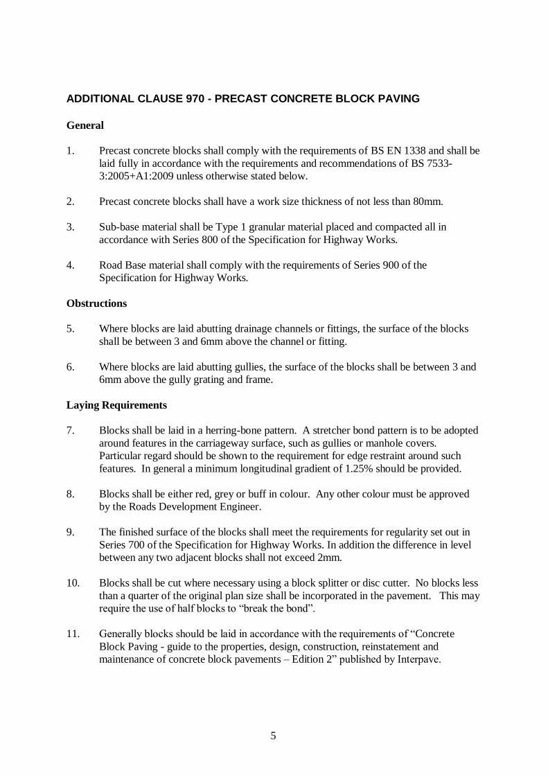
ADDITIONAL CLAUSE 970 - PRECAST CONCRETE BLOCK PAVING
General
1. Precast concrete blocks shall comply with the requirements of BS EN 1338 and shall be
laid fully in accordance with the requirements and recommendations of BS 7533-
3:2005+A1:2009 unless otherwise stated below.
2. Precast concrete blocks shall have a work size thickness of not less than 80mm.
3. Sub-base material shall be Type 1 granular material placed and compacted all in
accordance with Series 800 of the Specification for Highway Works.
4. Road Base material shall comply with the requirements of Series 900 of the
Specification for Highway Works.
Obstructions
5. Where blocks are laid abutting drainage channels or fittings, the surface of the blocks
shall be between 3 and 6mm above the channel or fitting.
6. Where blocks are laid abutting gullies, the surface of the blocks shall be between 3 and
6mm above the gully grating and frame.
Laying Requirements
7. Blocks shall be laid in a herring-bone pattern. A stretcher bond pattern is to be adopted
around features in the carriageway surface, such as gullies or manhole covers.
Particular regard should be shown to the requirement for edge restraint around such
features. In general a minimum longitudinal gradient of 1.25% should be provided.
8. Blocks shall be either red, grey or buff in colour. Any other colour must be approved
by the Roads Development Engineer.
9. The finished surface of the blocks shall meet the requirements for regularity set out in
Series 700 of the Specification for Highway Works. In addition the difference in level
between any two adjacent blocks shall not exceed 2mm.
10. Blocks shall be cut where necessary using a block splitter or disc cutter. No blocks less
than a quarter of the original plan size shall be incorporated in the pavement. This may
require the use of half blocks to “break the bond”.
11. Generally blocks should be laid in accordance with the requirements of “Concrete
Block Paving - guide to the properties, design, construction, reinstatement and
maintenance of concrete block pavements – Edition 2” published by Interpave.

6
APPENDIX 0/3: LIST OF NUMBERED APPENDICES REFERRED TO IN THE SPECIFICATION
Appendix 0/3 is comprised of two lists, A and B, of Numbered Appendices as follows:
List ‘A’ is a list of the Numbered Appendices referred to in the Specification for Highway
Works.
List ‘B’ gives the list of specific Numbered Appendices devised for this guide.
List ‘A’: List of Numbered Appendices Referred to in the Specification
Appx
No.
Title
INTRODUCTION
0/3 List of Numbered Appendices Referred to in the Specification
0/4 List of Drawings.
PRELIMINARIES
1/5 Testing to be Carried Out by the Developer
1/6 Supply and Delivery of Samples to the Roads Development Engineer
SAFETY FENCES, SAFETY BARRIERS AND PEDESTRIAN
GUARDRAILS
4/2 Pedestrian Guardrails
DRAINAGE AND SERVICE DUCTS
5/1 Drainage Requirements
5/2 Service Duct Requirements
5/5 Combined Drainage and Kerb Systems
5/6 Linear Drainage Channel Systems
EARTHWORKS
6/1 Requirements for Acceptability & Testing etc. of Earthworks Materials
6/5 Geotextiles Used to Separate Earthworks Materials
6/7 Sub-formation & Capping & Preparation & Surface Treatment of Formation
6/8 Topsoiling
6/9 Earthwork Environmental Bunds, Landscape Areas, Strengthened
Embankments
ROAD PAVEMENTS – GENERAL
7/1 Permitted Pavement Options
7/2 Excavation, Repair and Reinstatement of Existing Surfaces
KERBS, FOOTWAYS AND PAVED AREAS
11/1 Kerbs, Footways & Paved Areas

7
Appx
No.
Title
TRAFFIC SIGNS
12/1 Traffic Signs: General
12/3 Traffic Signs: Road Markings and Studs
ROAD LIGHTING COLUMNS AND BRACKETS
13/1 Road Lighting Columns and Brackets
ELECTRICAL WORK FOR ROAD LIGHTING AND TRAFFIC
SIGNS
14/1 Site Records
14/2 Location of Lighting Units & Feeder Pillars
14/3 Temporary Lighting
14/4 Electrical Equipment for Road Lighting
14/5 Electrical Equipment for Traffic Signs
LANDSCAPE AND ECOLOGY 30/4 Ground Preparation
30/5 Grass Seeding, Wildflower Seeding and Turfing
30/6 Planting
30/7 Grass, Bulbs and Wildflower Maintenance
List ‘B’ gives the list of Specific Numbered Appendices Devised for these standards.
Appx.
No.
Appendix Title
7/70 Preparation of Surfacing and Adjustment of Iron Work
11/1A Footways and Paved Areas (Precast Concrete Paving)
11/1B Footways and Paved Areas (Flexible Construction)
11/1C Footways and Paved Areas (Insitu Concrete Paving)
11/1D Footways and Paved Areas (Concrete Block Paving)
11/1E Footways and Paved Areas (Granolithic Concrete Paving)
11/1F Footways and Paved Areas (Granite Sett Paving)
11/1G Footways and Paved Areas (Stone Slabbed Paving)
11/73 Footways and Paved Areas (Racking of Existing Kerbs, Setts and Slabs)
8
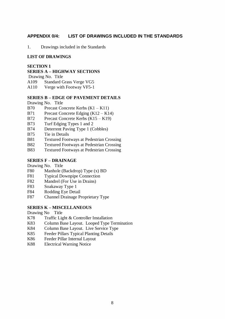
APPENDIX 0/4: LIST OF DRAWINGS INCLUDED IN THE STANDARDS
1. Drawings included in the Standards
LIST OF DRAWINGS
SECTION 1
SERIES A – HIGHWAY SECTIONS
Drawing No. Title
A109 Standard Grass Verge VG5
A110 Verge with Footway VF5-1
SERIES B – EDGE OF PAVEMENT DETAILS
Drawing No. Title
B70 Precast Concrete Kerbs (K1 – K11)
B71 Precast Concrete Edging (K12 – K14)
B72 Precast Concrete Kerbs (K15 – K19)
B73 Turf Edging Types 1 and 2
B74 Deterrent Paving Type 1 (Cobbles)
B75 Tie in Details
B81 Textured Footways at Pedestrian Crossing
B82 Textured Footways at Pedestrian Crossing
B83 Textured Footways at Pedestrian Crossing
SERIES F – DRAINAGE
Drawing No. Title
F80 Manhole (Backdrop) Type (x) BD
F81 Typical Downpipe Connection
F82 Mandrel (For Use in Drains)
F83 Soakaway Type 1
F84 Rodding Eye Detail
F87 Channel Drainage Proprietary Type
SERIES K – MISCELLANEOUS
Drawing No Title
K78 Traffic Light & Controller Installation
K83 Column Base Layout. Looped Type Termination
K84 Column Base Layout. Live Service Type
K85 Feeder Pillars Typical Planting Details
K86 Feeder Pillar Internal Layout
K88 Electrical Warning Notice
9
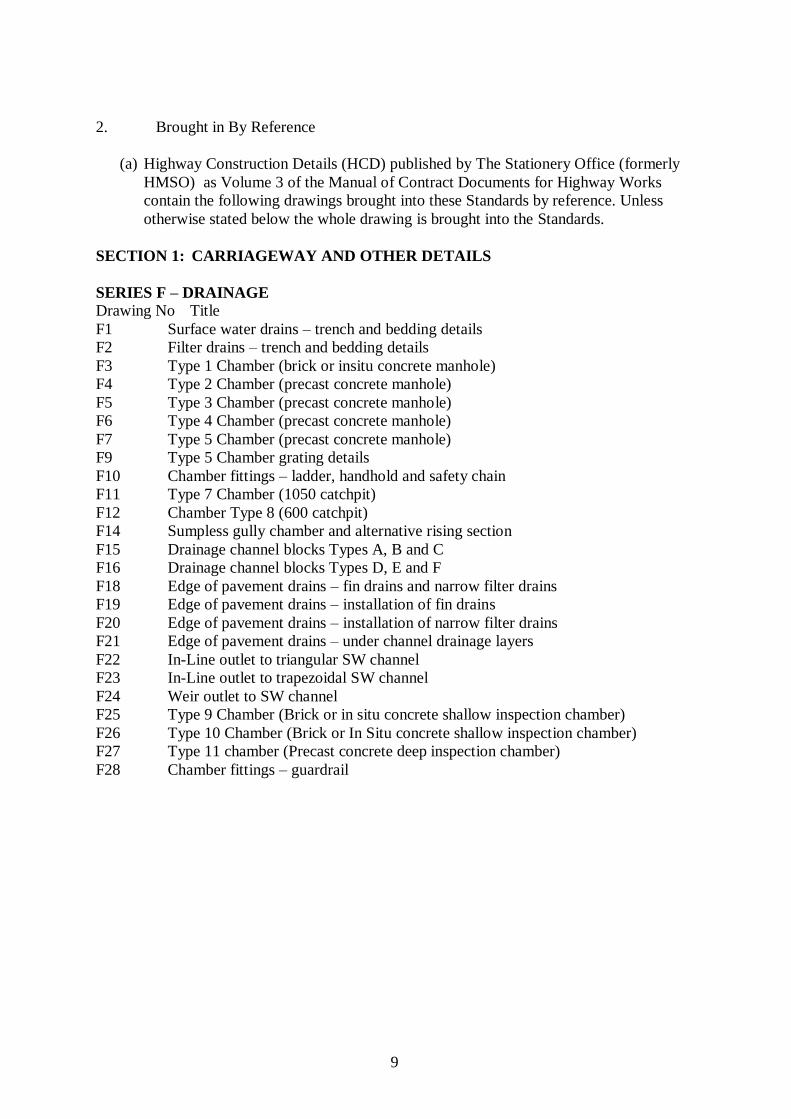
2. Brought in By Reference
(a) Highway Construction Details (HCD) published by The Stationery Office (formerly
HMSO) as Volume 3 of the Manual of Contract Documents for Highway Works
contain the following drawings brought into these Standards by reference. Unless
otherwise stated below the whole drawing is brought into the Standards.
SECTION 1: CARRIAGEWAY AND OTHER DETAILS
SERIES F – DRAINAGE
Drawing No Title
F1 Surface water drains – trench and bedding details
F2 Filter drains – trench and bedding details
F3 Type 1 Chamber (brick or insitu concrete manhole)
F4 Type 2 Chamber (precast concrete manhole)
F5 Type 3 Chamber (precast concrete manhole)
F6 Type 4 Chamber (precast concrete manhole)
F7 Type 5 Chamber (precast concrete manhole)
F9 Type 5 Chamber grating details
F10 Chamber fittings – ladder, handhold and safety chain
F11 Type 7 Chamber (1050 catchpit)
F12 Chamber Type 8 (600 catchpit)
F14 Sumpless gully chamber and alternative rising section
F15 Drainage channel blocks Types A, B and C
F16 Drainage channel blocks Types D, E and F
F18 Edge of pavement drains – fin drains and narrow filter drains
F19 Edge of pavement drains – installation of fin drains
F20 Edge of pavement drains – installation of narrow filter drains
F21 Edge of pavement drains – under channel drainage layers
F22 In-Line outlet to triangular SW channel
F23 In-Line outlet to trapezoidal SW channel
F24 Weir outlet to SW channel
F25 Type 9 Chamber (Brick or in situ concrete shallow inspection chamber)
F26 Type 10 Chamber (Brick or In Situ concrete shallow inspection chamber)
F27 Type 11 chamber (Precast concrete deep inspection chamber)
F28 Chamber fittings – guardrail

10
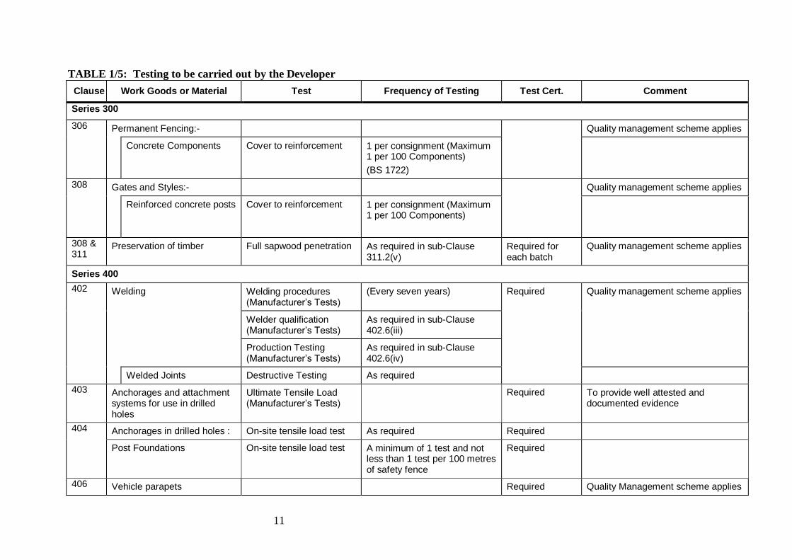
APPENDIX 1/5: TESTING TO BE CARRIED OUT BY THE DEVELOPER
Details of the testing to be carried out by the Developer is shown below in Table 1/5.
Notes:
1. Tests equivalent to those specified in this Appendix will be necessary for any
equivalent work, goods or materials proposed by the Developer (see Sub-clause
105.4).
2. (N) indicates that a UKAS sampling and test report or certificate is required.
3. Unless otherwise shown in this Appendix tests and test certifacates for work, goods or
materials as scheduled under any one Clause are required for all such work, goods or
materials.
4. Cube strength tests are not required for concrete complying with Clause 2602.
5. Sampling and testing will be carried out by the Developer to the frequency stated
below and at the Developer’s expense. All tests must be carried out by a
Laboratory which has UKAS accreditation for that specific test.
6. For imported materials sampled at source, the sample must be representative of the
material used in the works and the test certificate shall be no more than 12 months
old.
7. The Developer shall allow the Roads Development Engineer every reasonable
opportunity and facility to inspect and monitor the sampling and testing processes.
The Developer shall notify the Roads Development Engineer of who, where and when
samples and testing are being carried out and be able to demonstrate that the UKAS
accreditation required above is being complied with.
11
TABLE 1/5: Testing to be carried out by the Developer
Clause Work Goods or Material Test Frequency of Testing Test Cert. Comment
Series 300
306 Permanent Fencing:- Quality management scheme applies
Concrete Components Cover to reinforcement 1 per consignment (Maximum 1 per 100 Components)
(BS 1722)
308 Gates and Styles:- Quality management scheme applies
Reinforced concrete posts Cover to reinforcement 1 per consignment (Maximum 1 per 100 Components)
308 & 311
Preservation of timber Full sapwood penetration As required in sub-Clause 311.2(v)
Required for each batch
Quality management scheme applies
Series 400
402 Welding Welding procedures (Manufacturer’s Tests)
(Every seven years) Required Quality management scheme applies
Welder qualification (Manufacturer’s Tests)
As required in sub-Clause 402.6(iii)
Production Testing (Manufacturer’s Tests)
As required in sub-Clause 402.6(iv)
Welded Joints Destructive Testing As required
403 Anchorages and attachment systems for use in drilled holes
Ultimate Tensile Load (Manufacturer’s Tests)
Required To provide well attested and documented evidence
404 Anchorages in drilled holes : On-site tensile load test As required Required
Post Foundations On-site tensile load test A minimum of 1 test and not less than 1 test per 100 metres of safety fence
Required
406 Vehicle parapets Required Quality Management scheme applies
12
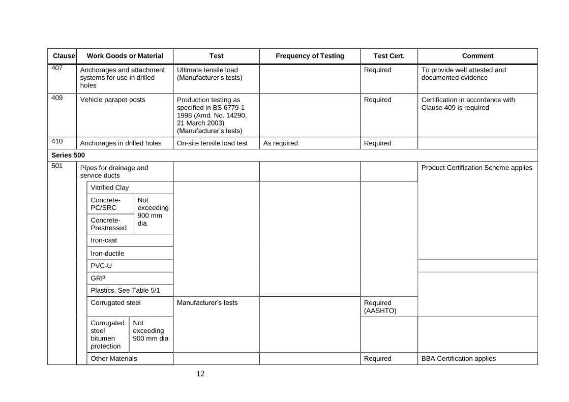
Clause Work Goods or Material Test Frequency of Testing Test Cert. Comment
407 Anchorages and attachment systems for use in drilled holes
Ultimate tensile load (Manufacturer’s tests)
Required To provide well attested and documented evidence
409 Vehicle parapet posts Production testing as specified in BS 6779-1 1998 (Amd. No. 14290, 21 March 2003) (Manufacturer’s tests)
Required Certification in accordance with Clause 409 is required
410 Anchorages in drilled holes On-site tensile load test As required Required
Series 500
501 Pipes for drainage and service ducts
Product Certification Scheme applies
Vitrified Clay
Concrete-PC/SRC
Not exceeding 900 mm dia Concrete-
Prestressed
Iron-cast
Iron-ductile
PVC-U
GRP
Plastics. See Table 5/1
Corrugated steel Manufacturer’s tests Required (AASHTO)
Corrugated steel bitumen protection
Not exceeding 900 mm dia
Other Materials Required BBA Certification applies
13
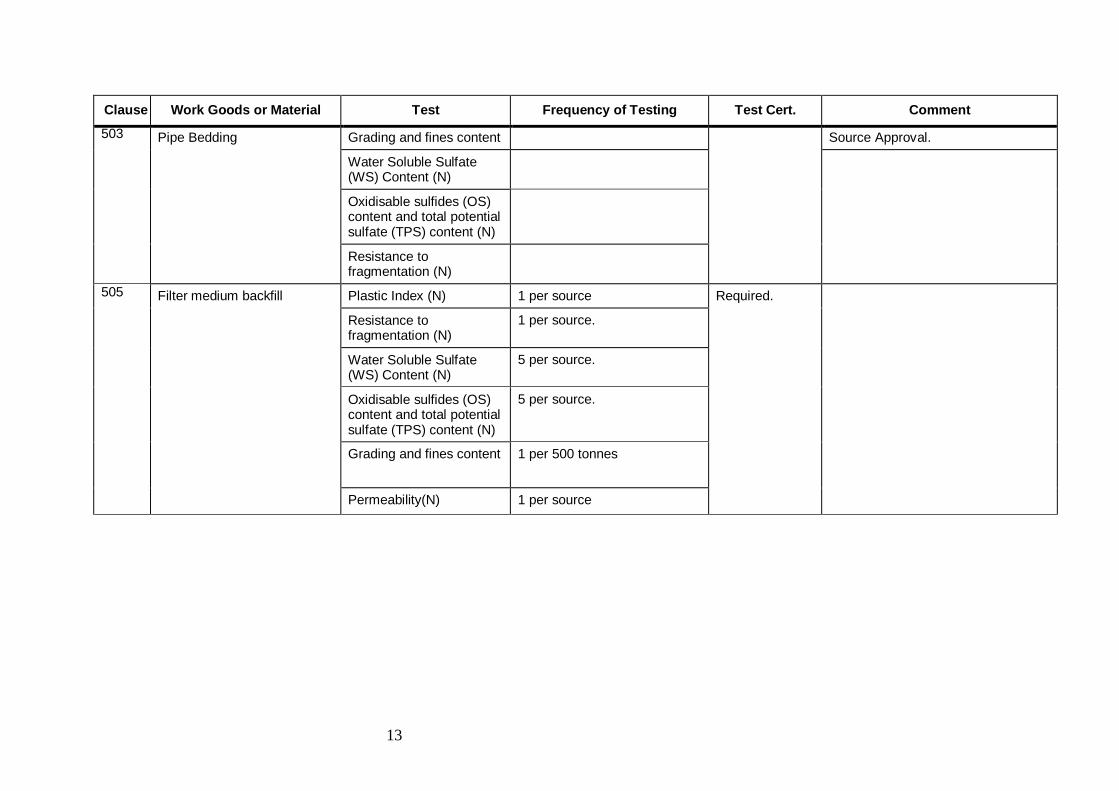
Clause Work Goods or Material Test Frequency of Testing Test Cert. Comment
503
Pipe Bedding Grading and fines content Source Approval.
Water Soluble Sulfate (WS) Content (N)
Oxidisable sulfides (OS) content and total potential sulfate (TPS) content (N)
Resistance to fragmentation (N)
505
Filter medium backfill Plastic Index (N) 1 per source Required.
Resistance to fragmentation (N)
1 per source.
Water Soluble Sulfate (WS) Content (N)
5 per source.
Oxidisable sulfides (OS) content and total potential sulfate (TPS) content (N)
5 per source.
Grading and fines content 1 per 500 tonnes
Permeability(N) 1 per source
14
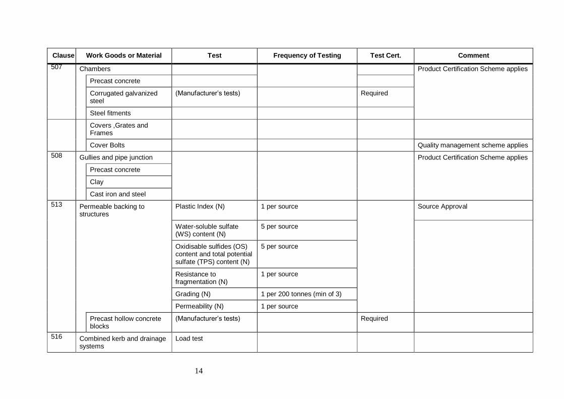
Clause Work Goods or Material Test Frequency of Testing Test Cert. Comment
507 Chambers Product Certification Scheme applies
Precast concrete
Corrugated galvanized steel
(Manufacturer’s tests) Required
Steel fitments
Covers ,Grates and Frames
Cover Bolts Quality management scheme applies
508 Gullies and pipe junction Product Certification Scheme applies
Precast concrete
Clay
Cast iron and steel
513 Permeable backing to structures
Plastic Index (N) 1 per source Source Approval
Water-soluble sulfate (WS) content (N)
5 per source
Oxidisable sulfides (OS) content and total potential sulfate (TPS) content (N)
5 per source
Resistance to fragmentation (N)
1 per source
Grading (N) 1 per 200 tonnes (min of 3)
Permeability (N) 1 per source
Precast hollow concrete blocks
(Manufacturer’s tests) Required
516 Combined kerb and drainage systems
Load test
15
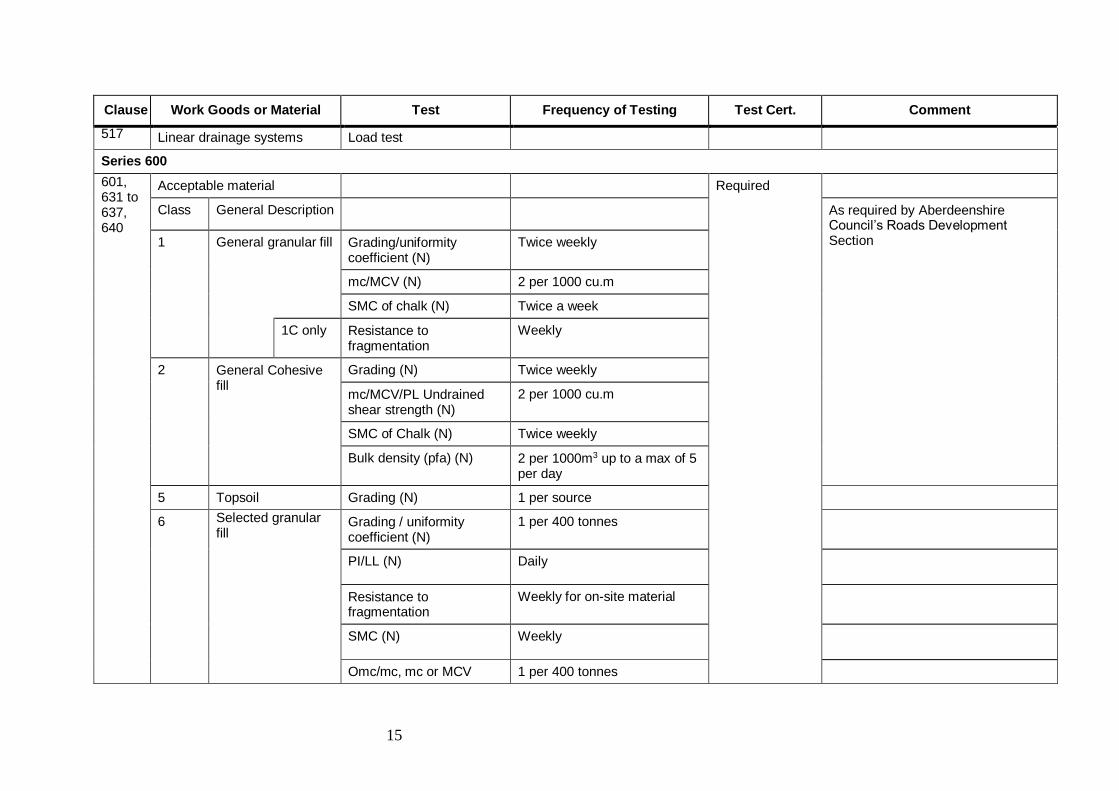
Clause Work Goods or Material Test Frequency of Testing Test Cert. Comment
517 Linear drainage systems Load test
Series 600
601, 631 to 637, 640
Acceptable material Required
Class General Description As required by Aberdeenshire Council’s Roads Development Section 1 General granular fill Grading/uniformity
coefficient (N) Twice weekly
mc/MCV (N) 2 per 1000 cu.m
SMC of chalk (N) Twice a week
1C only Resistance to fragmentation
Weekly
2 General Cohesive fill
Grading (N) Twice weekly
mc/MCV/PL Undrained shear strength (N)
2 per 1000 cu.m
SMC of Chalk (N) Twice weekly
Bulk density (pfa) (N) 2 per 1000m3 up to a max of 5 per day
5 Topsoil Grading (N) 1 per source
6 Selected granular fill
Grading / uniformity coefficient (N)
1 per 400 tonnes
PI/LL (N) Daily
Resistance to fragmentation
Weekly for on-site material
SMC (N) Weekly
Omc/mc, mc or MCV 1 per 400 tonnes
16
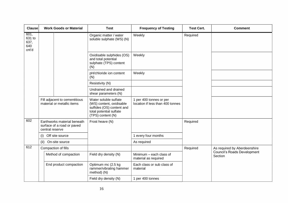
Clause Work Goods or Material Test Frequency of Testing Test Cert. Comment
601, 631 to 637, 640 cnt’d
Organic matter / water soluble sulphate (WS) (N)
Weekly Required
Oxidisable sulphides (OS) and total potential sulphate (TPS) content (N)
Weekly
pH/chloride ion content (N)
Weekly
Resistivity (N)
Undrained and drained shear parameters (N)
Fill adjacent to cementitious material or metallic items
Water soluble sulfate (WS) content, oxidisable sulfides (OS) content and total potential sulfate (TPS) content (N)
1 per 400 tonnes or per location if less than 400 tonnes
602 Earthworks material beneath surface of a road or paved central reserve
Frost heave (N) Required
(i) Off site source 1 every four months
(ii) On-site source As required
612 Compaction of fills Required As required by Aberdeenshire Council’s Roads Development Section
Method of compaction Field dry density (N) Minimum – each class of material as required
End product compaction
Optimum mc (2.5 kg rammer/vibrating hammer method) (N)
Each class or sub class of material
Field dry density (N) 1 per 400 tonnes
17
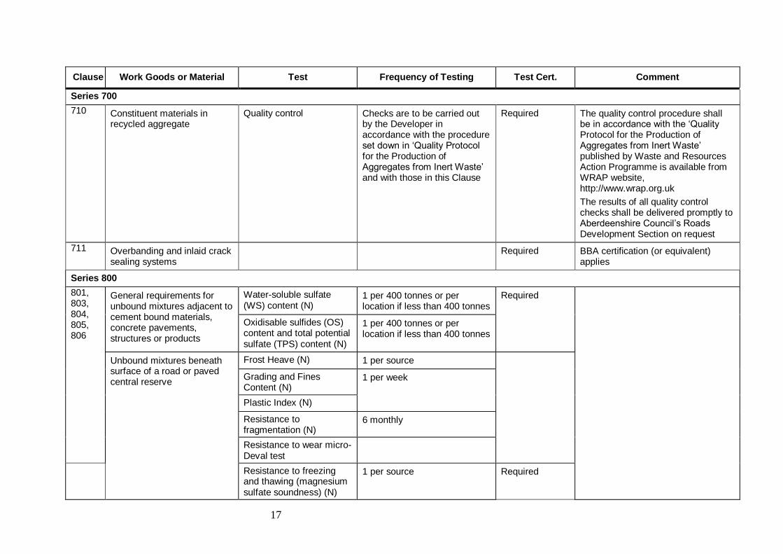
Clause Work Goods or Material Test Frequency of Testing Test Cert. Comment
Series 700
710 Constituent materials in recycled aggregate
Quality control Checks are to be carried out by the Developer in accordance with the procedure set down in ‘Quality Protocol for the Production of Aggregates from Inert Waste’ and with those in this Clause
Required The quality control procedure shall be in accordance with the ‘Quality Protocol for the Production of Aggregates from Inert Waste’ published by Waste and Resources Action Programme is available from WRAP website, http://www.wrap.org.uk
The results of all quality control checks shall be delivered promptly to Aberdeenshire Council’s Roads Development Section on request
711 Overbanding and inlaid crack sealing systems
Required BBA certification (or equivalent) applies
Series 800
801, 803, 804, 805, 806
General requirements for unbound mixtures adjacent to cement bound materials, concrete pavements, structures or products
Water-soluble sulfate (WS) content (N)
1 per 400 tonnes or per location if less than 400 tonnes
Required
Oxidisable sulfides (OS) content and total potential sulfate (TPS) content (N)
1 per 400 tonnes or per location if less than 400 tonnes
Unbound mixtures beneath surface of a road or paved central reserve
Frost Heave (N) 1 per source
Grading and Fines Content (N)
1 per week
Plastic Index (N)
Resistance to fragmentation (N)
6 monthly
Resistance to wear micro-Deval test
Resistance to freezing and thawing (magnesium sulfate soundness) (N)
1 per source Required

18
Clause Work Goods or Material Test Frequency of Testing Test Cert. Comment
Water Absorption (N)
Volume stability of blast furnace slags
6 monthly 801, 803, 804, 805, 806 cnt’d
Volume stability of steel (BOF and EAF) slags
CBR (N) 1 per source and then monthly
OMC/mc (N) 1 per source
Density (N)
Water absorption (N) As required
Series 900
901, 925, 937, 938, 943
Aggregates for bituminous materials
Required National quality management sector schemes apply
Resistance to fragmentation (hardness)
Resistance to fragmentation (N)
901, 925, 926, 938
Resistance to freezing and thawing (durability)
Soundness (N)
Water Absorption (N)
Cleanness Sieve test (mass passing 0.063 mm sieve) (N)
Washing and sieving method to be used
Shape Flakiness Index (N)
Blastfurnace slag Bulk density (N)
Soundness (N)
Dicalcium silicate disintegration (N)
Iron disintegration (N)
Steel slag Bulk density
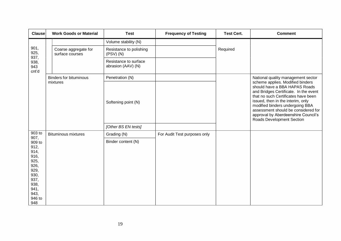
19
Clause Work Goods or Material Test Frequency of Testing Test Cert. Comment
Volume stability (N)
901, 925, 937, 938, 943 cnt’d
Coarse aggregate for surface courses
Resistance to polishing (PSV) (N)
Required
Resistance to surface abrasion (AAV) (N)
Binders for bituminous mixtures
Penetration (N) National quality management sector scheme applies. Modified binders should have a BBA HAPAS Roads and Bridges Certificate. In the event that no such Certificates have been issued, then in the interim, only modified binders undergoing BBA assessment should be considered for approval by Aberdeenshire Council’s Roads Development Section
Softening point (N)
[Other BS EN tests]
903 to 907, 909 to 912, 914, 916, 925, 926, 929, 930, 937, 938, 941, 943, 946 to 948
Bituminous mixtures Grading (N) For Audit Test purposes only
Binder content (N)
20
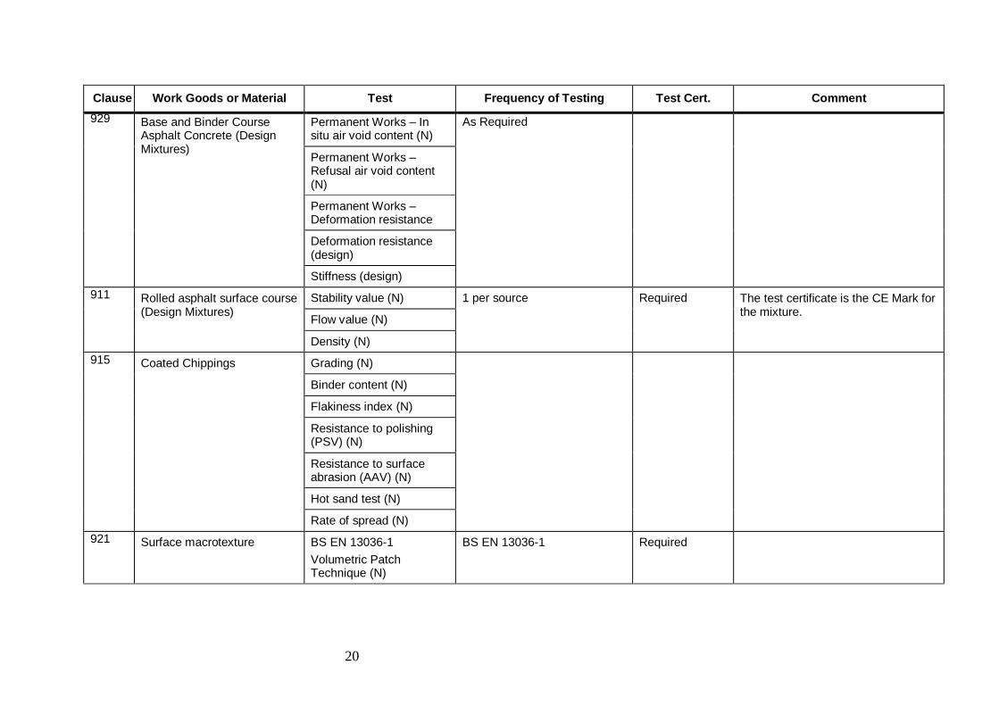
Clause Work Goods or Material Test Frequency of Testing Test Cert. Comment
929 Base and Binder Course Asphalt Concrete (Design Mixtures)
Permanent Works – In situ air void content (N)
As Required
Permanent Works – Refusal air void content (N)
Permanent Works – Deformation resistance
Deformation resistance (design)
Stiffness (design)
911 Rolled asphalt surface course (Design Mixtures)
Stability value (N) 1 per source Required The test certificate is the CE Mark for the mixture.
Flow value (N)
Density (N)
915 Coated Chippings Grading (N)
Binder content (N)
Flakiness index (N)
Resistance to polishing (PSV) (N)
Resistance to surface abrasion (AAV) (N)
Hot sand test (N)
Rate of spread (N)
921 Surface macrotexture BS EN 13036-1
Volumetric Patch Technique (N)
BS EN 13036-1 Required
21
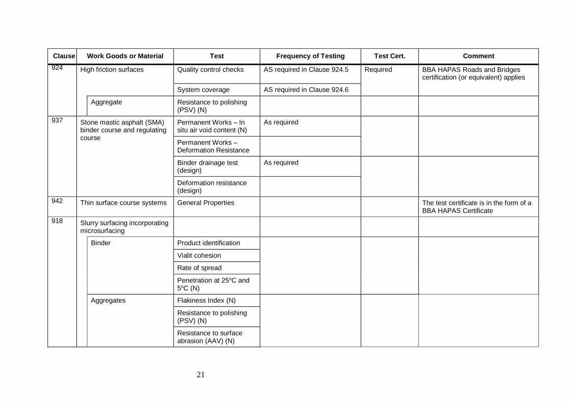
Clause Work Goods or Material Test Frequency of Testing Test Cert. Comment
924 High friction surfaces Quality control checks AS required in Clause 924.5 Required BBA HAPAS Roads and Bridges certification (or equivalent) applies
System coverage AS required in Clause 924.6
Aggregate Resistance to polishing (PSV) (N)
937 Stone mastic asphalt (SMA) binder course and regulating course
Permanent Works – In situ air void content (N)
As required
Permanent Works – Deformation Resistance
Binder drainage test (design)
As required
Deformation resistance (design)
942 Thin surface course systems General Properties The test certificate is in the form of a BBA HAPAS Certificate
918
Slurry surfacing incorporating microsurfacing
Binder Product identification
Vialit cohesion
Rate of spread
Penetration at 25oC and 5oC (N)
Aggregates Flakiness Index (N)
Resistance to polishing (PSV) (N)
Resistance to surface abrasion (AAV) (N)
22
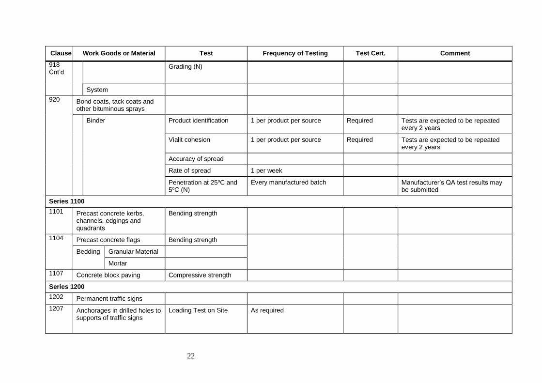
Clause Work Goods or Material Test Frequency of Testing Test Cert. Comment
918 Cnt’d
Grading (N)
System
920 Bond coats, tack coats and other bituminous sprays
Binder Product identification 1 per product per source Required Tests are expected to be repeated every 2 years
Vialit cohesion 1 per product per source Required Tests are expected to be repeated every 2 years
Accuracy of spread
Rate of spread 1 per week
Penetration at 25oC and 5oC (N)
Every manufactured batch Manufacturer’s QA test results may be submitted
Series 1100
1101 Precast concrete kerbs, channels, edgings and quadrants
Bending strength
1104 Precast concrete flags Bending strength
Bedding Granular Material
Mortar
1107 Concrete block paving Compressive strength
Series 1200
1202 Permanent traffic signs
1207 Anchorages in drilled holes to supports of traffic signs
Loading Test on Site As required
23
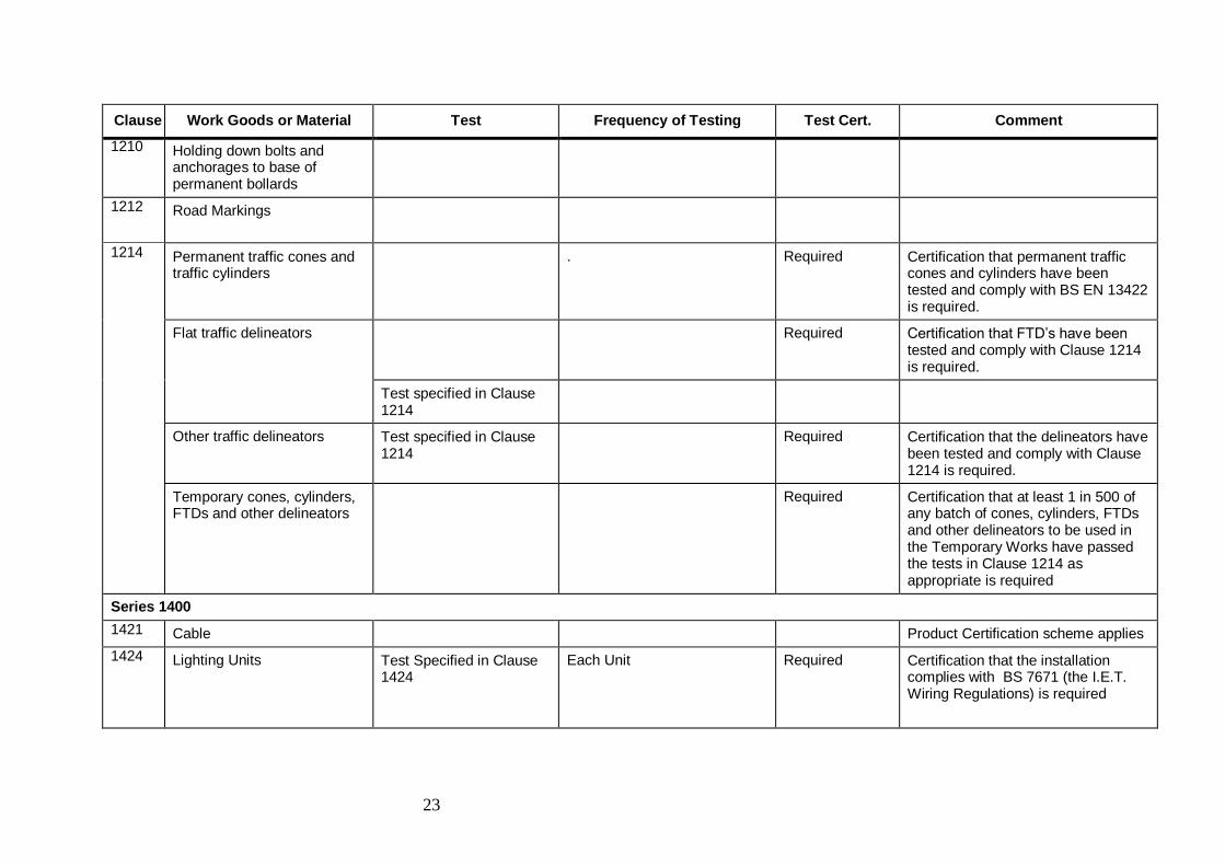
Clause Work Goods or Material Test Frequency of Testing Test Cert. Comment
1210 Holding down bolts and anchorages to base of permanent bollards
1212 Road Markings
1214 Permanent traffic cones and traffic cylinders
. Required Certification that permanent traffic cones and cylinders have been tested and comply with BS EN 13422 is required.
Flat traffic delineators Required Certification that FTD’s have been tested and comply with Clause 1214 is required.
Test specified in Clause 1214
Other traffic delineators Test specified in Clause 1214
Required Certification that the delineators have been tested and comply with Clause 1214 is required.
Temporary cones, cylinders, FTDs and other delineators
Required Certification that at least 1 in 500 of any batch of cones, cylinders, FTDs and other delineators to be used in the Temporary Works have passed the tests in Clause 1214 as appropriate is required
Series 1400
1421 Cable Product Certification scheme applies
1424
Lighting Units Test Specified in Clause 1424
Each Unit Required Certification that the installation complies with BS 7671 (the I.E.T. Wiring Regulations) is required
24
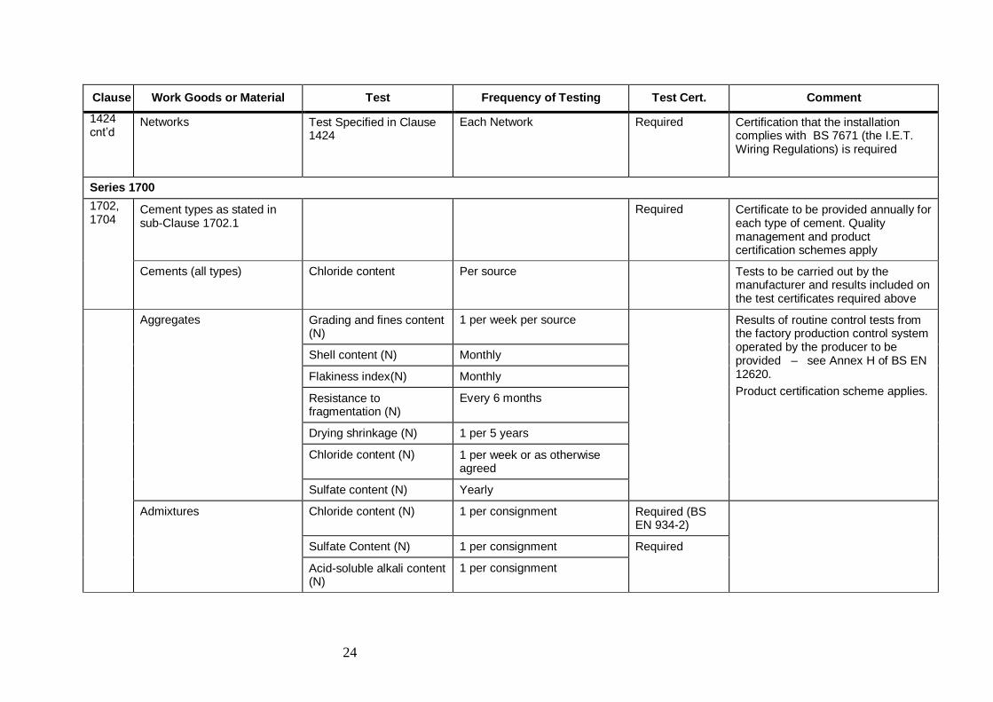
Clause Work Goods or Material Test Frequency of Testing Test Cert. Comment
1424 cnt’d
Networks Test Specified in Clause 1424
Each Network Required Certification that the installation complies with BS 7671 (the I.E.T. Wiring Regulations) is required
Series 1700
1702, 1704
Cement types as stated in sub-Clause 1702.1
Required Certificate to be provided annually for each type of cement. Quality management and product certification schemes apply
Cements (all types) Chloride content Per source Tests to be carried out by the manufacturer and results included on the test certificates required above
Aggregates Grading and fines content (N)
1 per week per source Results of routine control tests from the factory production control system operated by the producer to be provided – see Annex H of BS EN 12620.
Product certification scheme applies.
Shell content (N) Monthly
Flakiness index(N) Monthly
Resistance to fragmentation (N)
Every 6 months
Drying shrinkage (N) 1 per 5 years
Chloride content (N) 1 per week or as otherwise agreed
Sulfate content (N) Yearly
Admixtures Chloride content (N) 1 per consignment Required (BS EN 934-2)
Sulfate Content (N) 1 per consignment Required
Acid-soluble alkali content (N)
1 per consignment
25
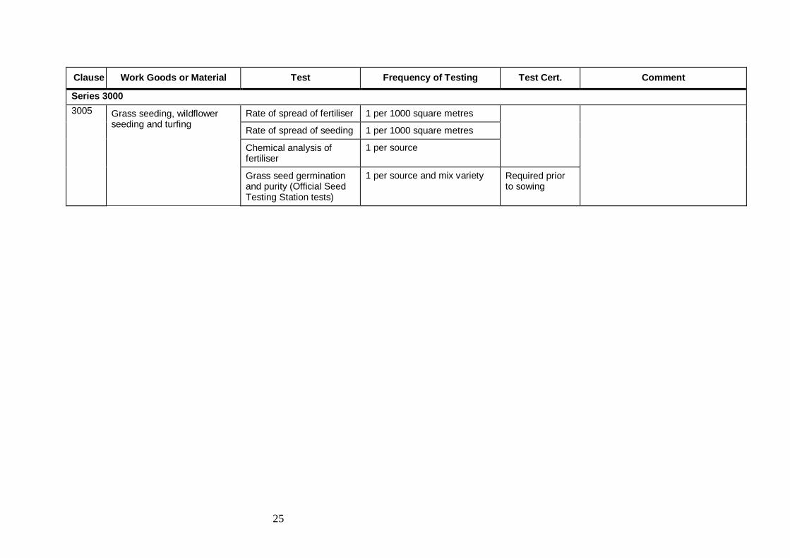
Clause Work Goods or Material Test Frequency of Testing Test Cert. Comment
Series 3000
3005
Grass seeding, wildflower seeding and turfing
Rate of spread of fertiliser 1 per 1000 square metres
Rate of spread of seeding 1 per 1000 square metres
Chemical analysis of fertiliser
1 per source
Grass seed germination and purity (Official Seed Testing Station tests)
1 per source and mix variety Required prior to sowing

26
APPENDIX 1/6: SUPPLY AND DELIVERY OF SAMPLES TO THE ROADS DEVELOPMENT ENGINEER
1. Notwithstanding the Developer’s obligations under Appendix 1/5 during the
construction period, irrespective of whether or not it is intended that the road(s) be
subsequently adopted as public, the Roads Development Engineer must be afforded
access to the site to ensure that the works are being undertaken in conformity with the
Construction Consent. The Developer and/or his Contractor shall provide every facility
to enable the Roads Development Engineer to examine the works being executed and
the materials being used.
2. They shall supply, free of cost, samples of the various material to be used together with
particulars as to the source of supply or manufacture of such materials.
3. Any costs incurred by the Local Roads Authority in undertaking the sampling or
testing of any materials will be recovered from the Developer, in accordance with the
terms of Section 140(6) of the Roads (Scotland) Act 1984

27
APPENDIX 4/2: PEDESTRIAN GUARDRAILS
1. All pedestrian guardrails shall comply with the requirements of BS 7818:1995. The
guardrails shall be designed to a minimum of Class 2 with full height vertical infill to a
minimum of Class B and provide adequate visibility as detailed in BS 7818:1995 Annex
B 2.5.
2. Posts are to be of a bolt down type and fitted in accordance with the manufactures
instructions.

28
APPENDIX 5/1: DRAINAGE REQUIREMENTS
Surface Water Drains – Materials
1. The following pipes meeting the requirements of Table 5/1 will be permitted.
(i) Vitrified clay
(ii) Precast concrete
(iii) Unplasticised P.V.C.
(iv) Ductile iron
(v) Polypropylene (with BBA Roads and Bridges Certificate)
2. For plastic pipes the Ultimate Pipe Stiffness when tested in accordance with BS 4962
shall be 1400 N/m2 and resistance to impact to comply with BS 4962 using a striker
drawing a mass of 1 kg and a hemispherical radius of 25mm.
Surface Water Drains – Bedding
3. Pipe and bedding combinations shall be determined from HA 40/01 (DMRB 4.2.5.1).
Filter Drains
4 Pipe and bedding combinations shall be determined from HA 40/01 (DMRB 4.2.5.1).
Gully Connections
5. In addition to material meeting 1 above, the use of flexible corrugated plastic pipes
will be permitted provided it is surrounded with 150mm ST2 concrete and its use
restricted to under verges etc.
Manholes
6 All manholes rings will require to be sealed with ‘Tokstrip’ or equivalent.
7. All manhole covers shall open such that an operative will have an unobscured view of
the oncoming traffic when entering or leaving the manhole.
8. All standard manhole covers will require to be Class D400 complying with BS EN
124:1994 and have third party accreditation On heavily trafficked routes the Roads
Development Engineer may specify the use of manhole covers, 150mm deep.
Testing of Pipes
9. All pipes to be ‘mandrel’ tested as directed by the Roads Development Engineer.
Cover of Pipes
10. All pipes with less than 900mm cover to formation to be surrounded in concrete as per
trench Type Z in Highway Construction Detail F1.
Gullies
11 All standard gully frames and gratings will require to be Class D400 complying with
BS EN 124:1994 and have third party accreditation

29
Adjustment of Iron Work
12 Adjustment, renewal, etc. of manhole covers, gully frames, surface boxes, tobies, etc.
shall be carried out immediately prior to commencing the wearing course, and shall be
ramped or protected, where necessary, if the road is open to the public.
13 Manholes, surface boxes, tobies, etc. shall be set flush with the adjoining finished
surface. Care shall be taken to remove old mortar and the frames shall be bedded on
2:1 cement mortar on top of additional engineering brick, as necessary, finished in a
header course.
14 An epoxy resin mortar of an approved type shall be used where traffic is required to
run over the cover within seven days of execution. The use of Polyester type mortars
will be permitted, provided the thickness of any layer does not exceed 12mm.
15. Gullies shall be set 6mm below the level of adjoining surface and shall be bedded as
above. If it is intended that the road shall be used before the wearing course is laid,
the Developer shall leave the gully gratings at a suitable level to permit drainage and
shall raise them to their final level at his expense prior to the wearing course being
laid. Care should be taken to seal the space between the gully grating and the kerb
with an approved bitumen material, or as directed by the Roads Development
Engineer.
16. Adjustment to levels of surface boxes will be made using standard precast concrete
units.
17. Where standard precast rings have been used to form manholes or catchpits, a
maximum of five courses of brick (old and new) will be allowed. Greater adjustment
will require the installation of a new precast ring similar to existing rings.
APPENDIX 5/2: SERVICE DUCT REQUIREMENTS
General
1. Ducts for Street Lighting, Illuminated Traffic Signs and Traffic Signals will be
100mm U.P.V.C. laid on a bed type T as shown on H.C.D. Drawing No F1.
2. Unless otherwise indicated by the appropriate statutory undertaker, ducts shall be
bedded on a bed Type T as shown on H.C.D. Drawing No F1 or similar.
3. The appropriate marking tape shall be placed 150mm above all cables and ducts laid
for services.

30
Colour of Ducts / Pipes
4. The colour of ducts will generally be as required by the authority. The following shall
apply unless otherwise stated: -
(i) Road Lighting including Traffic Bollards and Signs Purple
(ii) Traffic Signals Orange
(iii) British Telecom Grey
(iv) Scottish and Southern Energy Black
(v) Scottish Water Blue
(vi) SGN (gas) Yellow

31
APPENDIX 5/5: COMBINED DRAINAGE AND KERB SYSTEMS
General Requirements
1. Details of proposed combined drainage and kerb systems shall submitted for approval.
2. Components for combined drainage and kerb systems shall be from a single
manufacturer and designed and installed fully with the manufacturer’s
recommendations and requirements.
APPENDIX 5/6: LINEAR DRAINAGE CHANNEL SYSTEMS
General Requirements
1. Details of proposed linear drainage channel systems shall submitted for approval.
2. Components for linear drainage channel systems shall be from a single manufacturer
and designed and installed fully with the manufacturer’s recommendations and
requirements.

32
APPENDIX 6/1: REQUIREMENT FOR ACCEPTABILITY OF TESTING ETC. OF EARTHWORKS MATERIALS
Permitted Classes of Material
1 General Fill – Imported: Class 1A
2 The Developer shall demonstrate the acceptability of both imported fill material and
fill material arising from, and for use in, the site. The Developer shall submit test
results, the relevant tests being listed in Appendix 1/5, to the Roads Development
Engineer.
3 The MCV of acceptable material shall be > 8.5.
APPENDIX 6/5: GEOTEXTILES USED TO SEPARATE EARTHWORKS MATERIALS
General
1. Where a Geotextile is to be used as a separator under fill it shall be laid on top of the
subgrade.
Geotextile
2. The Geotextile shall be manufactured from synthetic fibres and have a minimum life
expectancy of 40 years.
The geotextile shall sustain a tensile load of not less than 10 kNn/m and shall have a
minimum axial strain of 20% at failure. It shall also have a minimum water flow at
right angles to its principal plane in either direction of 50 litres/sqm/sec.
Installation
3. The geotextile shall be laid from rolls in a longitudinal direction along the line of the
road. Jointing shall be by lapping only. Physical jointing will not be permitted. The
lap width shall be 500mm minimum.
Drawings
4. The locations where geotextiles are to be used in separation layers should be clearly
shown on the appropriate drawings

33
APPENDIX 6/7: SUB-FORMATION AND CAPPING AND PREPARATION AND SURFACE TREATMENT OF FORMATION
General
1. Details of the locations where Capping is required should be clearly shown on the
appropriate drawings.
2. Allowable surface level tolerance shall be as per Clause 616.
3. Capping shall be constructed with either Class 6F1 or 6F2 material as detailed in
Table 6/1.
4. The material shall be compacted at a moisture content within the range specified in
Table 6/1.
5. The C.B.R. value of the material shall be greater than 15%.
APPENDIX 6/8: TOPSOILING
1. Where areas are to be grass seeded they shall be topsoiled to a thickness of 150mm in
accordance with the requirements of Appendix 30/4.
APPENDIX 6/9: EARTHWORKS, ENVIRONMENTAL BUNDS, LANDSCAPE AREAS, STRENGTHEND EMBANKMENTS
Landscaped Areas – General
1. Where landscaping is required to be carried out the Developer will clearly indicate
these areas on the Consent drawings.
2. Where areas are to be planted with shrubs etc. they shall be topsoiled to a thickness of
300mm in accordance with the requirements of Appendix 30/4.

34
APPENDIX 7/1 PERMITTED PAVEMENT OPTIONS
1. Location: All adoptable roads
2. Grid for checking surface levels of pavement course
Longitudinal dimensions – 10 metres.
Transverse dimension - 2 metres.
Table 7/1: Tolerances in Surface Levels of Pavement Courses
Road Surfaces
- general
- adjustment to surface water channel
+/- 6mm
+ 10 – 0 mm
Binder Course +/- 6mm
Top surface of base in pavements without
Binder course
+/- 8mm
Base other than above +/- 15mm
Sub-base under concrete pavements surface
slabs laid full thickness in one operation by
machines with surface compaction
+/- 10mm
Sub-base +10 -30mm
3. Surface regularity
Compliance with the surface regularity will be checked in accordance with Clause
702 for a Category A road.
Table 7/2: Maximum Permitted Number of Surface Irregularities
Surfaces of carriageways,
hard strips and hard
shoulders
Surfaces of lay-bys, service
areas, all bituminous binder
courses and top surface of
base in pavements without
binder courses
Irregularity 4mm 7mm 4mm 7mm
Length 300 75 300 75 300 75 300 75
Category A Road 20 9 2 1 40 18 4 2
Category B Road 40 18 4 2 60 27 6 3
4. Texture Depth
Unless otherwise agreed, in writing, with the Roads Development Engineer all roads
with a speed limit greater than 50mph will be deemed to require texture depth as
specified below: -
Texture depth >= 1.5mm average and >= 1.2mm individual.
Texture depth will be measured in accordance with Clause 921.1.
5. Remedial Works
The Developer will be required to carry out remedial works within a 2 week period if
there is any standing water on a carriageway, footway, cycletrack, or footpath
constructed, reconstructed or reinstated under the Consent.
35
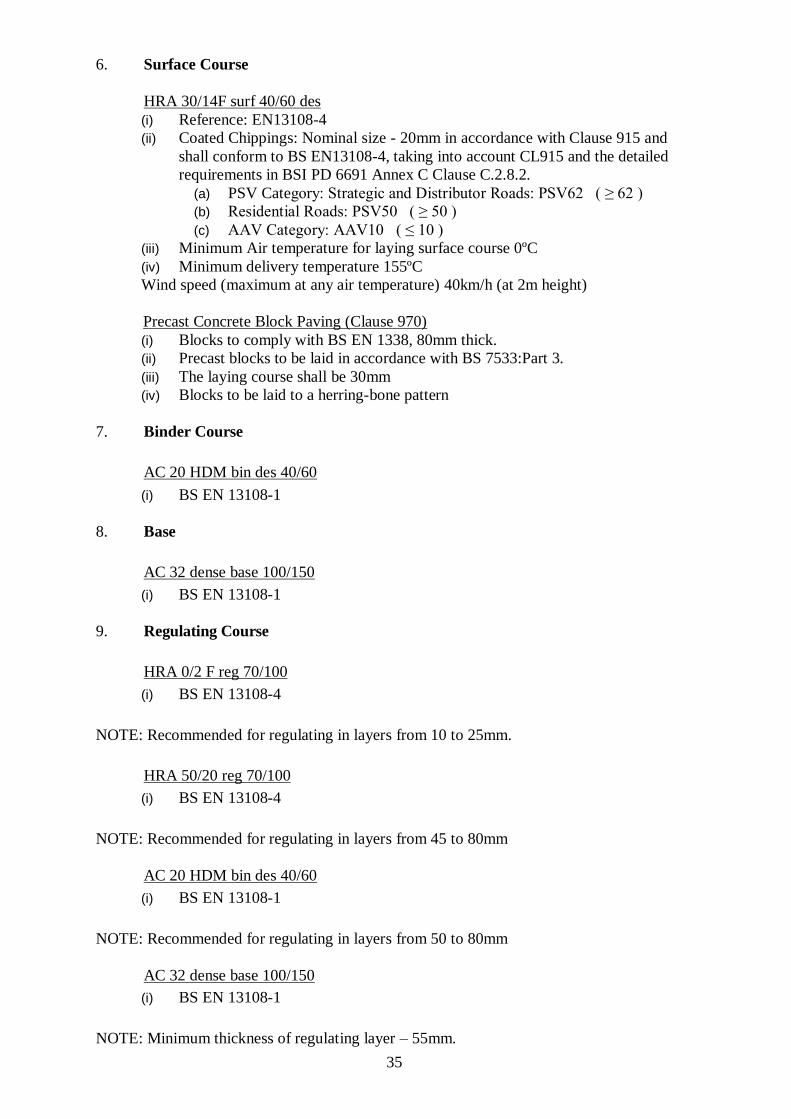
6. Surface Course
HRA 30/14F surf 40/60 des
(i) Reference: EN13108-4
(ii) Coated Chippings: Nominal size - 20mm in accordance with Clause 915 and
shall conform to BS EN13108-4, taking into account CL915 and the detailed
requirements in BSI PD 6691 Annex C Clause C.2.8.2.
(a) PSV Category: Strategic and Distributor Roads: PSV62 ( ≥ 62 )
(b) Residential Roads: PSV50 ( ≥ 50 )
(c) AAV Category: AAV10 ( ≤ 10 )
(iii) Minimum Air temperature for laying surface course 0ºC
(iv) Minimum delivery temperature 155ºC
Wind speed (maximum at any air temperature) 40km/h (at 2m height)
Precast Concrete Block Paving (Clause 970)
(i) Blocks to comply with BS EN 1338, 80mm thick.
(ii) Precast blocks to be laid in accordance with BS 7533:Part 3.
(iii) The laying course shall be 30mm
(iv) Blocks to be laid to a herring-bone pattern
7. Binder Course
AC 20 HDM bin des 40/60
(i) BS EN 13108-1
8. Base
AC 32 dense base 100/150
(i) BS EN 13108-1
9. Regulating Course
HRA 0/2 F reg 70/100
(i) BS EN 13108-4
NOTE: Recommended for regulating in layers from 10 to 25mm.
HRA 50/20 reg 70/100
(i) BS EN 13108-4
NOTE: Recommended for regulating in layers from 45 to 80mm
AC 20 HDM bin des 40/60
(i) BS EN 13108-1
NOTE: Recommended for regulating in layers from 50 to 80mm
AC 32 dense base 100/150
(i) BS EN 13108-1
NOTE: Minimum thickness of regulating layer – 55mm.

36
10. Sub-base
Type 1 Unbound Mixture (Clause 803)
(i) Minimum (C.B.R. - 30%)
(ii) Frost Heave in accordance with BS 812: Part 124
APPENDIX 7/2: EXCAVATION, REPAIR AND REINSTATEMENT OF EXISTING SURFACES
1. The location of trenches, pits etc., which require to be excavated in the existing paved
surface in order to carry out the Works to be shown on the Consent drawings.
2. The location and estimated areas of existing paved areas which require to be trimmed,
regulated and reinstated to match levels where new and existing pavements abut to be
shown on the Consent drawings.
General
3. Reinstatements shall comply with the “Specification for the Reinstatement of
Openings in Roads – Third Edition (Scotland)” published by Transport Scotland. The
appropriate categories shall be agreed with the Roads Development Engineer.
Excavation and Reinstatement in the Vicinity of Existing Trees
4. All excavation and reinstatement works adjacent to existing trees must be carried out in
accordance with the “Guidelines for Planning, Installation and Maintenance of Utility
Services in Proximity to trees” published by The National Joint Utility Group.
Cutting of Existing Blacktop Surfaces
5. Effective dust control techniques (either local exhaust ventilation or wet dust
suppression methods) must be employed where the use of “Saw Cutting” is required.
APPENDIX 7/70: PREPARATION FOR SURFACING AND ADJUSTMENT OF IRONWORK
Preparation for Surfacing
1. Prior to laying surfacing material, the existing road surface shall be cleaned, brushed
and free of all loose material. The surface as a whole shall be dry and be completely
free of standing water and any dampness.
Adjustment of Iron Work
2. Adjustment, renewal, etc. of manhole covers, gully frames, surface boxes, and tobies,
etc. shall, where practicable, be carried out immediately prior to laying the wearing
course or regulating course, otherwise ironwork shall be ramped or protected where
necessary if the road is open to the public.
37
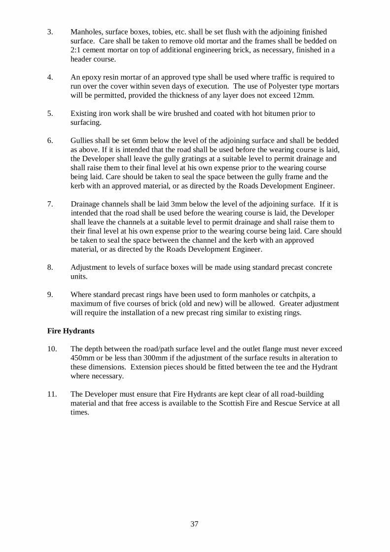
3. Manholes, surface boxes, tobies, etc. shall be set flush with the adjoining finished
surface. Care shall be taken to remove old mortar and the frames shall be bedded on
2:1 cement mortar on top of additional engineering brick, as necessary, finished in a
header course.
4. An epoxy resin mortar of an approved type shall be used where traffic is required to
run over the cover within seven days of execution. The use of Polyester type mortars
will be permitted, provided the thickness of any layer does not exceed 12mm.
5. Existing iron work shall be wire brushed and coated with hot bitumen prior to
surfacing.
6. Gullies shall be set 6mm below the level of the adjoining surface and shall be bedded
as above. If it is intended that the road shall be used before the wearing course is laid,
the Developer shall leave the gully gratings at a suitable level to permit drainage and
shall raise them to their final level at his own expense prior to the wearing course
being laid. Care should be taken to seal the space between the gully frame and the
kerb with an approved material, or as directed by the Roads Development Engineer.
7. Drainage channels shall be laid 3mm below the level of the adjoining surface. If it is
intended that the road shall be used before the wearing course is laid, the Developer
shall leave the channels at a suitable level to permit drainage and shall raise them to
their final level at his own expense prior to the wearing course being laid. Care should
be taken to seal the space between the channel and the kerb with an approved
material, or as directed by the Roads Development Engineer.
8. Adjustment to levels of surface boxes will be made using standard precast concrete
units.
9. Where standard precast rings have been used to form manholes or catchpits, a
maximum of five courses of brick (old and new) will be allowed. Greater adjustment
will require the installation of a new precast ring similar to existing rings.
Fire Hydrants
10. The depth between the road/path surface level and the outlet flange must never exceed
450mm or be less than 300mm if the adjustment of the surface results in alteration to
these dimensions. Extension pieces should be fitted between the tee and the Hydrant
where necessary.
11. The Developer must ensure that Fire Hydrants are kept clear of all road-building
material and that free access is available to the Scottish Fire and Rescue Service at all
times.
38
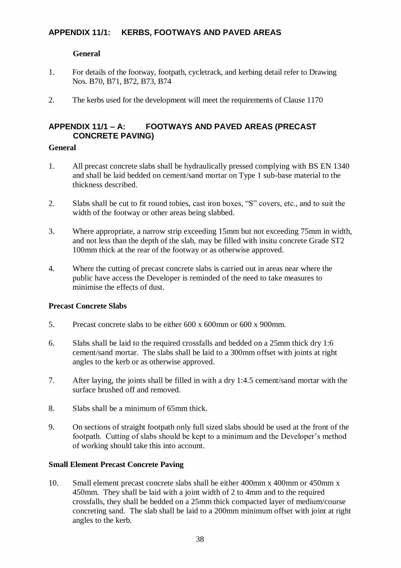
APPENDIX 11/1: KERBS, FOOTWAYS AND PAVED AREAS
General
1. For details of the footway, footpath, cycletrack, and kerbing detail refer to Drawing
Nos. B70, B71, B72, B73, B74
2. The kerbs used for the development will meet the requirements of Clause 1170
APPENDIX 11/1 – A: FOOTWAYS AND PAVED AREAS (PRECAST CONCRETE PAVING)
General
1. All precast concrete slabs shall be hydraulically pressed complying with BS EN 1340
and shall be laid bedded on cement/sand mortar on Type 1 sub-base material to the
thickness described.
2. Slabs shall be cut to fit round tobies, cast iron boxes, “S” covers, etc., and to suit the
width of the footway or other areas being slabbed.
3. Where appropriate, a narrow strip exceeding 15mm but not exceeding 75mm in width,
and not less than the depth of the slab, may be filled with insitu concrete Grade ST2
100mm thick at the rear of the footway or as otherwise approved.
4. Where the cutting of precast concrete slabs is carried out in areas near where the
public have access the Developer is reminded of the need to take measures to
minimise the effects of dust.
Precast Concrete Slabs
5. Precast concrete slabs to be either 600 x 600mm or 600 x 900mm.
6. Slabs shall be laid to the required crossfalls and bedded on a 25mm thick dry 1:6
cement/sand mortar. The slabs shall be laid to a 300mm offset with joints at right
angles to the kerb or as otherwise approved.
7. After laying, the joints shall be filled in with a dry 1:4.5 cement/sand mortar with the
surface brushed off and removed.
8. Slabs shall be a minimum of 65mm thick.
9. On sections of straight footpath only full sized slabs should be used at the front of the
footpath. Cutting of slabs should be kept to a minimum and the Developer’s method
of working should take this into account.
Small Element Precast Concrete Paving
10. Small element precast concrete slabs shall be either 400mm x 400mm or 450mm x
450mm. They shall be laid with a joint width of 2 to 4mm and to the required
crossfalls, they shall be bedded on a 25mm thick compacted layer of medium/course
concreting sand. The slab shall be laid to a 200mm minimum offset with joint at right
angles to the kerb.

39
11. After laying, sand should be spread over the joints and the slabs bedded in using a
rubber based vibrating plate and sand swept over the surface until the joints are full.
12. Slabs shall be a minimum of 65mm thick.
Increased Thickness of Sub-Base
13. Further to the above the thickness of the sub-base shall be increased to 150mm at
vehicular crossings or other such thickness as may be indicated in the Consent for other
areas of footway strengthening.
Paving Thickness Schedule
14. The thickness of sub-base is given in the Paving Thickness Schedule Table 11/1A.
Table 11/1A: Thickness Schedule Precast Concrete Paving (mm)
Precast Contract Slabs Small element Precast Concrete Slabs
Sub-base 100 150
Binder
Course
25 6/1 Sand/Cement
mix
25 course sand
Surface
Course
65 slab, jointing sand
as required
65 slab, jointing sand as required
APPENDIX 11/1 – B: FOOTWAYS AND PAVED AREAS (FLEXIBLE CONSTRUCTION)
General
1. The flexible surfacing shall be laid in accordance with the appropriate British
Standard.
2. The finished depth of the wearing course shall not deviate by more than 5mm from
the depth specified.
3. The finished footway, footpath, or cycletrack shall not deviate from the specified level
more than +/- 6mm.
4. The whole footway, footpath, or cycletrack surface will be checked for surface
regularity and shall have no irregularity exceeding +/- 5mm in 3 metres.
5. For checking compliance with the requirement transversely to the kerb on widths less
than 3 metres, no irregularities shall exceed +/- 5mm on a straight edge laid across the
full width of the new surface.
6. Surfaces out of tolerance shall have the full depth of the layer cut out and replaced
with new material. The width shall be the footway width, and the minimum length to
be removed shall be 2.0 metres
40
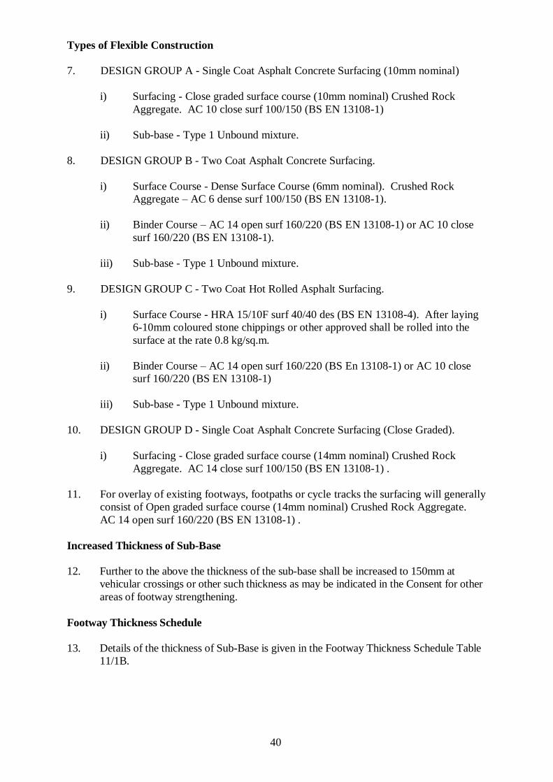
Types of Flexible Construction
7. DESIGN GROUP A - Single Coat Asphalt Concrete Surfacing (10mm nominal)
i) Surfacing - Close graded surface course (10mm nominal) Crushed Rock
Aggregate. AC 10 close surf 100/150 (BS EN 13108-1)
ii) Sub-base - Type 1 Unbound mixture.
8. DESIGN GROUP B - Two Coat Asphalt Concrete Surfacing.
i) Surface Course - Dense Surface Course (6mm nominal). Crushed Rock
Aggregate – AC 6 dense surf 100/150 (BS EN 13108-1).
ii) Binder Course – AC 14 open surf 160/220 (BS EN 13108-1) or AC 10 close
surf 160/220 (BS EN 13108-1).
iii) Sub-base - Type 1 Unbound mixture.
9. DESIGN GROUP C - Two Coat Hot Rolled Asphalt Surfacing.
i) Surface Course - HRA 15/10F surf 40/40 des (BS EN 13108-4). After laying
6-10mm coloured stone chippings or other approved shall be rolled into the
surface at the rate 0.8 kg/sq.m.
ii) Binder Course – AC 14 open surf 160/220 (BS En 13108-1) or AC 10 close
surf 160/220 (BS EN 13108-1)
iii) Sub-base - Type 1 Unbound mixture.
10. DESIGN GROUP D - Single Coat Asphalt Concrete Surfacing (Close Graded).
i) Surfacing - Close graded surface course (14mm nominal) Crushed Rock
Aggregate. AC 14 close surf 100/150 (BS EN 13108-1) .
11. For overlay of existing footways, footpaths or cycle tracks the surfacing will generally
consist of Open graded surface course (14mm nominal) Crushed Rock Aggregate.
AC 14 open surf 160/220 (BS EN 13108-1) .
Increased Thickness of Sub-Base
12. Further to the above the thickness of the sub-base shall be increased to 150mm at
vehicular crossings or other such thickness as may be indicated in the Consent for other
areas of footway strengthening.
Footway Thickness Schedule
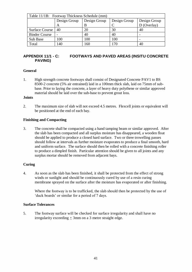
13. Details of the thickness of Sub-Base is given in the Footway Thickness Schedule Table
11/1B.
41
Table 11/1B: Footway Thickness Schedule (mm)
Design Group
A
Design Group
B
Design Group
C
Design Group
D (Overlay)
Surface Course 40 20 30 40
Binder Course - 40 40 -
Sub Base 100 100 100 -
Total 140 160 170 40
APPENDIX 11/1 - C: FOOTWAYS AND PAVED AREAS (INSITU CONCRETE PAVING)
General
1. High strength concrete footways shall consist of Designated Concrete PAV1 to BS
8500-2 concrete (5% air entrained) laid in a 100mm thick slab, laid on 75mm of sub-
base. Prior to laying the concrete, a layer of heavy duty polythene or similar approved
material should be laid over the sub-base to prevent grout loss.
Joints
2. The maximum size of slab will not exceed 4.5 metres. Flexcell joints or equivalent will
be positioned at the end of each bay.
Finishing and Compacting
3. The concrete shall be compacted using a hand tamping beam or similar approved. After
the slab has been compacted and all surplus moisture has disappeared, a wooden float
should be applied to produce a closed hard surface. Two or three trowelling passes
should follow at intervals as further moisture evaporates to produce a final smooth, hard
and uniform surface. The surface should then be rolled with a concrete finishing roller
to produce a dimpled finish. Particular attention should be given to all joints and any
surplus mortar should be removed from adjacent bays.
Curing
4. As soon as the slab has been finished, it shall be protected from the effect of strong
winds or sunlight and should be continuously cured by use of a resin curing
membrane sprayed on the surface after the moisture has evaporated or after finishing.
Where the footway is to be trafficked, the slab should then be protected by the use of
‘duck boards’ or similar for a period of 7 days.
Surface Tolerances
5. The footway surface will be checked for surface irregularity and shall have no
irregularity exceeding + 3mm on a 3 metre straight edge.
42
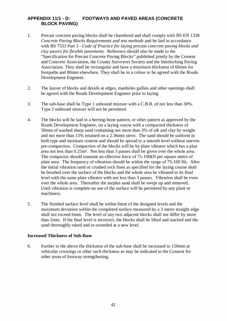
APPENDIX 11/1 - D: FOOTWAYS AND PAVED AREAS (CONCRETE BLOCK PAVING)
1. Precast concrete paving blocks shall be chamfered and shall comply with BS EN 1338
Concrete Paving Blocks Requirements and test methods and be laid in accordance
with BS 7533 Part 3 - Code of Practice for laying precast concrete paving blocks and
clay pavers for flexible pavements. Reference should also be made to the
“Specification for Precast Concrete Paving Blocks” published jointly by the Cement
and Concrete Association, the County Surveyors Society and the Interlocking Paving
Association. They shall be rectangular and have a minimum thickness of 60mm for
footpaths and 80mm elsewhere. They shall be in a colour to be agreed with the Roads
Development Engineer.
2. The layout of blocks and details at edges, manholes gullies and other openings shall
be agreed with the Roads Development Engineer prior to laying.
3. The sub-base shall be Type 1 unbound mixture with a C.B.R. of not less than 30%.
Type 2 unbound mixture will not be permitted.
4. The blocks will be laid in a herring-bone pattern, or other pattern as approved by the
Roads Development Engineer, on a laying course with a compacted thickness of
50mm of washed sharp sand containing not more than 3% of silt and clay by weight
and not more than 15% retained on a 2.36mm sieve. The sand should be uniform in
both type and moisture content and should be spread to a smooth level without uneven
pre-compaction. Compaction of the blocks will be by plate vibrator which has a plan
area not less than 0.25m². Not less than 3 passes shall be given over the whole area.
The compactor should transmit an effective force of 75-100kN per square metre of
plate area. The frequency of vibration should be within the range of 75-100 Hz. After
the initial vibration sand or crushed rock fines as specified for the laying course shall
be brushed over the surface of the blocks and the whole area be vibrated to its final
level with the same plate vibrator with not less than 3 passes. Vibration shall be even
over the whole area. Thereafter the surplus sand shall be swept up and removed.
Until vibration is complete no use of the surface will be permitted by any plant or
machinery.
5. The finished surface level shall be within 6mm of the designed levels and the
maximum deviation within the completed surface measured by a 3 metre straight edge
shall not exceed 6mm. The level of any two adjacent blocks shall not differ by more
than 2mm. If the final level is incorrect, the blocks shall be lifted and stacked and the
sand thoroughly raked and re-screeded at a new level.
Increased Thickness of Sub-Base
6. Further to the above the thickness of the sub-base shall be increased to 150mm at
vehicular crossings or other such thickness as may be indicated in the Consent for
other areas of footway strengthening.
43
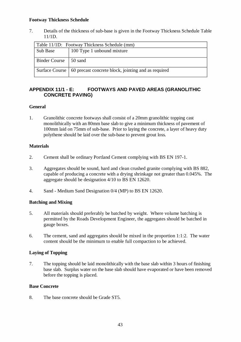
Footway Thickness Schedule
7. Details of the thickness of sub-base is given in the Footway Thickness Schedule Table
11/1D.
Table 11/1D: Footway Thickness Schedule (mm)
Sub Base 100 Type 1 unbound mixture
Binder Course 50 sand
Surface Course 60 precast concrete block, jointing and as required
APPENDIX 11/1 - E: FOOTWAYS AND PAVED AREAS (GRANOLITHIC CONCRETE PAVING)
General
1. Granolithic concrete footways shall consist of a 20mm granolithic topping cast
monolithically with an 80mm base slab to give a minimum thickness of pavement of
100mm laid on 75mm of sub-base. Prior to laying the concrete, a layer of heavy duty
polythene should be laid over the sub-base to prevent grout loss.
Materials
2. Cement shall be ordinary Portland Cement complying with BS EN 197-1.
3. Aggregates should be sound, hard and clean crushed granite complying with BS 882,
capable of producing a concrete with a drying shrinkage not greater than 0.045%. The
aggregate should be designation 4/10 to BS EN 12620.
4. Sand - Medium Sand Designation 0/4 (MP) to BS EN 12620.
Batching and Mixing
5. All materials should preferably be batched by weight. Where volume batching is
permitted by the Roads Development Engineer, the aggregates should be batched in
gauge boxes.
6. The cement, sand and aggregates should be mixed in the proportion 1:1:2. The water
content should be the minimum to enable full compaction to be achieved.
Laying of Topping
7. The topping should be laid monolithically with the base slab within 3 hours of finishing
base slab. Surplus water on the base slab should have evaporated or have been removed
before the topping is placed.
Base Concrete
8. The base concrete should be Grade ST5.
44
Joints
9. The maximum size of slab will not exceed 4.5 metres. An approved construction joint
will be positioned at the end of each bay.
Finishing and Compacting
10. The concrete should be compacted using a hand tamping beam or similar approved.
After the topping has been compacted, and all surplus moisture has disappeared, a
wooden float should be applied to produce a closed and hard surface. Two or three
trowelling passes should follow at interims as further moisture evaporates to produce a
final smooth, hard and uniform surface. The surface should then be rolled with a
concrete finishing roller to produce a dimpled finish. Particular attention should be
given to all joints and any surplus mortar should be removed from adjacent bays.
Curing
11. As soon as the topping has been finished, it should be protected from the effect of
strong winds or sunlight and should be continuously cured by use of a resin curing
membrane sprayed on the surface after the moisture sheen has evaporated or after
final trowelling.
12 The topping should then be protected by the use of ‘duck boards’ or similar for a
period of 7 days.
Surface Tolerances
13. The footway surface will be checked for surface regularity and shall have no
irregularity exceeding + 3mm on a 3 metre straight edge.
APPENDIX 11/1 - F: FOOTWAYS AND PAVED AREAS (GRANITE SETT PAVING)
General
1. Before laying setts shall be cleaned of all bituminous material soil, grit or other matter.
Sett Paving
2. Granite sett paving shall comply fully with the requirements and recommendations of
BS 7533 parts 7 and 10.
45
APPENDIX 11/1 - G: FOOTWAYS AND PAVED AREAS (STONE SLABBED PAVING)
General
1. Stone slab paving shall comply fully with the requirements and recommendations of
BS 7533 parts 4, 8 and 12.
2. Slabs shall be laid to the required crossfalls. The slabs shall be laid to a random offset
with the courses at right angles to the kerb and over the full width of the footway or as
otherwise approved.
3. Slabs shall be selected to fit round tobies, cast iron “S” covers, etc., and to suit the
width of the footway or other areas being slabbed. Otherwise, slabs should be cut as
required.
4. Where appropriate, at the rear of the footway, narrow strip not exceeding 75mm in
width and not less than 75mm in depth, maybe filled with insitu concrete Grade ST2
100mm thick.
APPENDIX 11/73: FOOTWAYS AND PAVED AREAS (RACKING OF EXISTING KERBS, SETTS AND SLABS)
1. Racking of existing kerbs, setts and slabs is defined as the adjustment insitu of kerbs,
setts or slabs by raising the packing.
2. The racked lengths or areas should be well packed with a 1:3 cement/sand mortar and
beaten to the level or falls directed.
3. The racked areas of setts and slabs shall be grouted with a 1:3 cement/sand mortar so
that all joints are completely filled and all surplus mortar brushed off and removed.
46
APPENDIX 12/1: TRAFFIC SIGNS - GENERAL REQUIREMENT FOR TRAFFIC SIGNS
General Requirements for Traffic Signs
1. The signs and accessories shall conform in all respects with the Traffic Signs
Regulations and General Directions, the Traffic Signs Manual, BS EN 12899-1
(Fixed, vertical road traffic signs) and BS 8408 for microprismatic sheeting.
2. The Developer may be required to supply 2 sets of the working drawings of the signs
prior to the commencement of manufacture of the signs.
3. Unless otherwise indicated signs should be designed to withstand a wind pressure of
15 millibars (156 kg/sq.m.).
4. All traffic signs shall be permanently marked on the reverse side with an identifier
consisting of the name or code of the Manufacturer, the month and year of
manufacture and an identification no. supplied by the Roads Development Engineer.
Sign Face Sheeting
5. Microprismatic Reflective Sheeting
(i) Microprismatic sheeting exceeds the performance requirements of Class Ref 2.
(ii) The material shall comply with the requirements of BS8408:2005 (and the sign
constructed to BS EN 12899-1).
(iii) The sign face sheeting and coloured overlay films and non-reflective sheeting
shall carry a minimum 12 year warranty, be from a single sheeting supplier and
supported by the sheeting manufacturer’s written traffic sign warranty.
6. Class Ref 2 Glass Bead Sheeting
(i) The material shall comply with the requirements of BS EN 12899-1.
(ii) The sign face sheeting and coloured overlay films and non-reflective sheeting
shall carry a minimum 10 year warranty, be from a single sheeting supplier and
supported by the sheeting manufacturer’s written traffic sign warranty.
7. Class Ref 1 Glass Bead Sheeting
(i) The material shall comply with the requirements of BS EN 12899-1.
(ii) The sign face sheeting and coloured overlay films and non-reflective sheeting
shall carry a minimum 7 year warranty, be from a single sheeting supplier and
supported by the sheeting manufacturer’s written traffic sign warranty.
8. Optional Specification for anti-graffiti sign faces
(i) An approved transparent protective Overlay Film (POF) shall be applied to the
surface of the sign face during manufacture. The POF shall allow the easy
removal of all types of graffiti including self adhesive paper or vinyl labels after
they have weathered, and further shall allow the application and easy removal
of a temporary sign face when required.

47
Framing
9. Sign reinforcement shall be spaced as necessary for the sign mounting and support
requirements taking account of post spacing, offsets, overhangs etc to ensure
compliance with BS EN 12899-1.
10. Corners of signs shall have a radius.
Backing Boards
11. Chapter 7 of the Traffic Signs Manual provides guidance on the use of backing boards.
12. Where signs on backing boards are back to back the boards shall be the same size.
13. The front of any backing board for signs shall be grey unless otherwise specified yellow
for road safety reasons. However use of higher performing fluorescent yellow material
should only be considered in exceptional circumstances.
Posts (Supports) and Foundations for Permanent Traffic Signs
14. Guidance for compliance with BS EN 12899-1:2007 is available in the document “Sign
Structures Guide: Support Design for Permanent UK Traffic Signs” published by the
Institute of Highway Incorporated Engineers. Software in accordance with the design
requirements is available; however a competent Quality Assured sign manufacturer can
also provide appropriate support options and foundation details.
15. Types and sizes of foundations will vary depending on a number of factors including
the location, wind loading, sign dimensions, mounting height, support type and ground
conditions.
16. On high speed roads supports shall comply with BS EN 12767 (Passive safety of support
structures for road equipment).
(i) Galvanised steel posts that are deemed to comply are grade S355J2H (3.2mm
nominal wall thickness) no greater than 89mm diameter.
(ii) If two posts are required for a single sign and post centres are less than 1500mm,
post dimensions should not exceed 76mm diameter.
(iii) Where post centres are 1500mm or greater, post dimensions shall not exceed
89mm.
17. Unless otherwise specified, all illuminated sign assemblies shall be provided with at
least one large based post to accommodate the necessary electrical equipment. The
electrical housing shall comply with BS EN 12899-1 and should be of a size suitable
for the electrical equipment being used. The base housing compartment may be circular
or rectangular in section or alternatively side slung boxes to the electrical equipment
may be attached to a standard post. The nominal door opening should be 500mm x
108mm.
18. In the case of illuminated signs particular attention should be given to the siting of the
posts. The post having the control base housing should be furthest away from the
carriageway and care shall be taken when positioning lanterns on poles to ensure that
they do not obstruct the view of the sign from the road.

48
Location and Erection of Permanent Traffic Signs
19. Attention is drawn to the recommendations and advice given in the Traffic Signs
Manual.
Lighting of Signs
20. Direct illumination of permanent traffic signs and types of luminaires shall be
constructed to comply with the requirements of BS EN 12899-1 and CIE 54.
21. Traffic Signs shall be lit by internal or external illumination where this is required by
Schedule 17 of the Traffic Signs Regulations and General Directions. Where
illumination by reflectorisation is permitted this shall be used in preference to internal
or external illumination.
22. If a sign is externally illuminated the bottom of the light unit must be between 0 to
25mm below the top of the sign.
Clearance of Signs
23. Vertical clearance to all new signs mounted on posts or lighting columns in footways
should be a minimum of 2.3 metres. The clearance in verges or central reserves will be
dependant on the type of supports used to comply with BS EN 12767
24. Horizontal clearance from the edge of carriageway should be at least 0.5 metres in areas
where the speed limit is 40mph or less and 1.2 metres where the speed is greater than
40mph.
Street Name Plates
25. Street Name Plates shall have a white microprismatic background to BS8408 with a
blue transparent overlay film and cut out lettering unless otherwise specified.
26. In some environmental areas (where agreed) the overlay film may be non-transparent
black.
27. The font shall be 88mm Kindersley with letter spacing increased by 60%. On signs with
more than one street name (e.g. “leading to” etc) the size of the letters for the follow-on
streets may be reduced by a maximum of 20% to control the overall size of the sign.
28. Sign plates shall be 11 swg aluminium with minimum 10mm radius corners.
29. The sign shall be erected on 50mm diameter posts so that the top of the sign is no more
than 1 metre above the adjacent road, and set between 3 and 5 metres back from the
junction line.
Permanent Bollards
30. Permanent bollards shall be of the solar-powered retroreflective self-righting type and
conform to BS EN 12899-2 and BS 8442 Section 14 as appropriate. All permanent
bollards shall be provided with a strengthened base constructed of steel which has
been hot dipped galvanised.

49
APPENDIX 12/3: ROAD MARKINGS
1. Where the Developer is required to lay road markings he shall comply with the
following requirements:-
i) Where road markings are removed, all junction markings shall be applied
within 24 hours. This requirement may be met initially by the application of
temporary markings which must be maintained until the permanent markings
are applied.
ii) All permanent road markings shall be applied within 2 weeks following any
removal of existing road markings.
iii) During any period of absence of road markings signs to diagram 7012 of the
“Traffic Signs Regulations and General Directions” (TSO 2002) shall be
erected and maintained.
iv) Where a marking is laid on top or partially on top of an existing marking, the
Developer shall be responsible for ensuring that the resulting combined
marking complies with the current Traffic Signs & General Directions.
2. The works shall be undertaken in accordance with the requirements of BS EN 1436
and the following: -
i) All loose material shall be removed from the surface before the markings are
applied.
ii) Road marking materials shall only be applied to surfaces which are dry and
clean. Markings shall be free from raggedness at their edges and shall be
uniform and free from streaks. Longitudinal road markings shall be laid by
approved mechanical means to a regular alignment.
iii) Sprayed markings shall be applied by an approved pressure spraying unit to a
thickness not less than 3.0mm exclusive of any surface glass beads.
iv) Screed markings shall be laid to a thickness not less than 4.0mm and not
greater than 5.0mm exclusive of any surface glass beads.
v) Extruded markings shall be laid to a thickness not less than 3.0mm exclusive
of any surface glass beads.
vi) Immediately following the application of material for any white markings,
Class B solid glass beads shall be applied to the surface of the laid
thermoplastic.
3. The material used for white markings shall be high performance thermoplastic
complying with the requirements of BS EN 1436 and the following: -
i) Retroflective Class R2
Luminance Class B2
Skid Resistance Class S2
50
All permanent road markings other than “High Performance” shall have a skid
resistance Class S1, except for arrows and worded markings having a large surface
area which shall be skid resistance Class S2.
ii) Certificate of Compliance
The material must be a Kitemark product (or equivalent) and a test Certificate not
more than 6 months old shall be provided detailing compliance with the requirements
of BS EN 1436 and with the modifications given in paragraph (i) and ii).
Once approved no substitute materials will be allowed without evidence of
compliance with the Specification as detailed above.
iii) Containers
The thermoplastic shall be supplied in powder form in low melting point bags to form
a composite material when heated (BS EN 1436 Part 1 Section 9).
iv) Performance
Skid Resistance
Under normal conditions the skid resistance value shall not be less than 50 when
measured by the Transport and Road Research Laboratory Portable Skid Resistance
Tester (Road Research Note No 27) throughout the marking’s guaranteed lift.
4. The material used for yellow markings shall be thermoplastic complying with the
requirements of BS EN 1436.
5. Yellow thermoplastic road markings shall be non-reflectorised and normally be
coloured “lemon” to BS 381C No 355.
6. Where the Developer is required to remove existing road markings, this shall be
undertaken carefully using hot compressed air. Damage to the road surface shall be
avoided.
Road Studs – Reflecting
7. Details of the layout and colour of the reflecting Road Studs to be shown on the
Consent Drawings.
Reflecting road studs shall be either: -
i) Self wiping “Cats Eye” type produced by Reflecting Roadstuds Limited.
ii) “Stimsonite 948” produced by Ennis-Flint.
or equivalent.
All centre-line road studs shall have bi-directional white lenses

51
Road Studs - Installation
8. “Cats Eyes” - shall be 254mm long, the studs shall be installed using methods
described in the 1995 “Instructions for Paving and General Maintenance. The studs are
to be laid true to line and level. The tip of the stud shall be not more than 25mm +
(0mm to 3mm) above the adjoining carriageway. The grout fill to the side cavity shall
consist of 75% filler of slate or other approved dust, 25% bitumen 60-80 pen.
“Stimsonite 948” - shall be installed in accordance with the manufacturer’s instructions.
If required by the Roads Development Engineer all Road Studs eyes are to be
thoroughly washed and cleaned immediately before the opening of the carriageway and
any settlement rectified.
Road Studs - Non-reflective
9. Studs shall where specified be white, silver or light grey in colour and shall not be fitted
with reflective lenses. The studs shall be either circular in shape with a diameter of not
more than 110 millimetres or less than 95 millimetres or square in shape with each side
being not more than 110 millimetres or less than 95 millimetres. Any stud shall not
project more than 18 millimetres above the carriageway at its highest point nor more
than 6 millimetres at its edges.
10. The studs shall conform to BS 8442.
Waiting Restrictions
11. Where the Consent indicates that yellow thermoplastic lines are to be provided in
waiting restrictions, these should not be laid on site till instructions are received from
the Roads Development Engineer in writing confirming that all required Traffic Orders
are in place.

52
APPENDIX 13/1: ROAD LIGHTING COLUMNS AND BRACKETS
General Requirements
1. Road lighting columns and brackets shall comply with the requirements of the following
standards :-
BS EN 40-1 Definitions and terms
BS EN 40-2 General Requirements and Dimensions
BS EN 40-3-1 Design & Verification – Characteristic Loads
BS EN 40-3-2 Design & Verification – Verification by Testing
BS EN 40-3-3 Design & Verification – verification by Calculation
BS EN 40-5 Requirements for Steel Lighting Columns
BS EN 40-6 Requirements for Aluminium Columns
2. Weld procedures shall be submitted to the Roads Development Engineer for perusal
prior to fabrication
3. The manufacturer shall inspect and test welds during production and shall provide
copies of test results when requested by the Roads Development Engineer
4. Road lighting columns and brackets shall also comply with the following additional
requirements.
Series 6000 Aluminium Alloy Columns
5. Columns shall have a design life of 50 years.
(i) Columns and brackets shall be structurally designed to be capable of accepting
lanterns with the following minimum weight and wind loading using the
projections and terrain category factors specified:-
Height Weight Projection Wind
Loading
Maximum
Lantern
Surface
Area
Terrain
Category
4/5
metre
(Sign)
16 kg n/a Extra
Heavy
0.15m² III
5 metre 16 kg n/a Extra
Heavy
0.15m² III
6 metre 16 kg n/a Extra
Heavy
0.15m² III
8 metre 18kg n/a Extra
Heavy
0.15m² II
10 metre 20kg n/a Extra
Heavy
0.15m² II
12 metre 22kg n/a Extra
Heavy
0.15m² II

53
6. The design wind loading shall be as BS EN 40-3-1 and PD6547:2004 with A1:2009
except that:
(a) The use of rationalised wind loading factors shall not be permitted
(b) The 10 minute mean wind velocity shall be taken as 27 m/sec
(c) The characteristic wind pressure derived shall be multiplied by a funnelling
factor of 1.05
(d) The characteristic wind pressure derived shall be multiplied by a gust factor
of 1.10.
7. Design of all lighting columns shall allow for the attachment of a sign of 5Kg x 0.30
square metre with a shape coefficient of 1.8 mounted 2500mm above ground level and
300mm eccentrically. Traffic sign columns shall be as lighting columns except that they
will require to allow for a sign of 15kg x 1.2m².
8. Columns and brackets shall carry a unique identification mark which indicates the name
of the manufacturer, the year of production and other design information to enable
details of the column and bracket to be determined throughout their design life. This
information shall be located at the top of the backboard such that it is clearly visible
after installation of the column.
9. The identification plate shall also have room for the installation contractor to append
his name and the date of erection of the column. Plate metal tags are to be supplied for
site fitting.
10. Columns shall be manufactured from a 6000 series aluminium alloy to the following
specification or equivalent:-
(a) Alloy to be used: EN AW – 6063
(b) Temper: T4 – T6
(c) Chemical Symbols: EN AW – AIMgO, 7Si
11. Columns shall be extruded in one piece form a regular tapered or conical shape. They
shall be equipped with a locking flush fitting door complete with separate earth
connection. If not extruded in one piece without joins, the supplier shall demonstrate
full compliance with BS EN 1999-1-1:2007 & A1:2009 especially with respect to heat
affected zones and shall be designed such that they can be used with pole-top mounting
lanterns using a 76mm spigot.
12. Columns shall be internally strengthened by suitable means around door openings.
13. Columns shall have a minimum base tube diameter of 145mm for 3 to 6 metre columns
and 165mm for 8 to 12 metre columns.
14. Lighting column bases shall comply with the requirements of BS EN 40 and shall have
a minimum unrestricted door opening of 600mm High x 100mm Wide.
54
15. Column base compartments shall be fitted with a stainless steel earth stud size M8 x 30
complete with 2 hexagon nuts and 2 plain washers. These shall be fitted to the earth lug
with a distinctly marked durable plastic label stating:
“SAFETY – ELECTRICAL CONNECTION – DO NOT REMOVE”
The label and lettering shall be as per BS 7671 Section 514.13.1 and the earth stud
shall be located at the lower left-hand side of the door opening.
16. Door openings shall be free from irregularities and burrs and all doors shall have a
suitable earthing point on their internal surface.
17. Columns shall be supplied with a flush fitting door having upper and lower locking
devices which shall be lubricated during assembly and suitably protected against
weather ingress for storage periods up to 18 months..
18. Keys shall be provided for 10% of all columns supplied. On delivery the door shall be
supplied assembled to the column.
19. The column shall be fitted with an internal full length baseboard of treated hardwood at
least equivalent to the door size. The board shall be securely fixed in the base
compartment by two sliding fasteners.
20. There shall be no sharp edges within the columns or spigots which could cause damage
to electrical cabling, during installation or in service.
21. The cable inlet hole(s) shall be a minimum size of 175 x 75mm and be fitted with a
subterranean cable protection sleeve to prevent cable chaffing.
22. The root section shall be protected to the outer and inner surfaces of the column to a
height of 250mm above ground level and shall be such that no ground or water course
pollution is caused.
23. The recommended column planting depth shall be indicated by means of an adhesive
label fixed to the column with the following information:-
(a) Installation:- Do not damage the column root protection during installation.
(b) Earthing:- Column body shall be earthed by means of M8 earthing terminal
on the internal mounting rail.
(c) Lighting Fixture:- Do not exceed the calculated values for the weight (kg)
and projected area (m²) of the lantern.
24. The base of the column shall have a high-density plastic protector fitted to prevent
damage to the root protection during installation. This protector is to remain in position
after the column is installed.
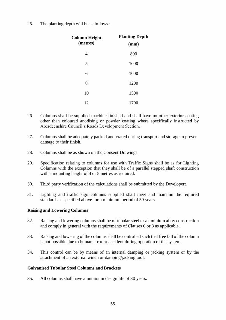
55
25. The planting depth will be as follows :-
Column Height
(metres)
Planting Depth
(mm)
4 800
5 1000
6 1000
8 1200
10 1500
12 1700
26. Columns shall be supplied machine finished and shall have no other exterior coating
other than coloured anodising or powder coating where specifically instructed by
Aberdeenshire Council’s Roads Development Section.
27. Columns shall be adequately packed and crated during transport and storage to prevent
damage to their finish.
28. Columns shall be as shown on the Consent Drawings.
29. Specification relating to columns for use with Traffic Signs shall be as for Lighting
Columns with the exception that they shall be of a parallel stepped shaft construction
with a mounting height of 4 or 5 metres as required.
30. Third party verification of the calculations shall be submitted by the Developerr.
31. Lighting and traffic sign columns supplied shall meet and maintain the required
standards as specified above for a minimum period of 50 years.
Raising and Lowering Columns
32. Raising and lowering columns shall be of tubular steel or aluminium alloy construction
and comply in general with the requirements of Clauses 6 or 8 as applicable.
33. Raising and lowering of the columns shall be controlled such that free fall of the column
is not possible due to human error or accident during operation of the system.
34. This control can be by means of an internal damping or jacking system or by the
attachment of an external winch or damping/jacking tool.
Galvanised Tubular Steel Columns and Brackets
35. All columns shall have a minimum design life of 30 years.
56
36. Design of all columns shall allow for the attachment of a sign of 5Kg x 0.30 square
metre with a shape coefficient of 1.8 mounted 2500mm above ground level and 300mm
eccentrically.
37. The columns and brackets shall be manufactured from steel which meets the
requirements of BS EN 40. Columns shall be of tubular steel design and shall be
manufactured from the following:
(a) Hot finished circular hollow sections to EN10210 Part 1 Grade S275 JOH
or S355 JOH.
(b) Cold formed circular hollow sections without subsequent treatment to the
dimensional requirements of EN10219 Part 2 and the chemical and
mechanical properties of EN10219 Part 1 Grade S275 JOH or S355 JOH.
The hot finished feedstock material shall comply with the yield, tensile and
elongation requirements of the required grade specified in BS EN 10025.
38. Columns and brackets shall carry a unique identification mark which indicates the name
of the manufacturer, the year of production and other design information to enable
details of the column and bracket to be determined throughout their design life. This
information should be located such that it is clearly visible after installation of the
column (i.e. internally in the column base).
39. Bracket sleeves shall fit over a reduced diameter spigot to maintain the smooth parallel
line between the column and the bracket arm. The bracket arm shall be secured in
position using stainless steel socket screws allowing fixing in any one of four 90 degree
positions relative to the door opening.
40. A means of preventing undesired rotational movement of the bracket once fixed in
position on the column shaft shall be incorporated in the column/bracket design.
41. Brackets arms shall be of tubular steel, incorporate a welded web, and have an incline
of 5 degrees constant rise.
42. The column base to shaft joint shall be of hot swaged and welded construction with an
internal centralising washer.
43. Suitable scale drawings shall be provided detailing the appearance and all dimensional
measurements, including outside diameters of the columns and brackets, prior to
installation.
44. Column doors shall be fitted with a locking device suitable for outside use and which is
corrosion resistant for a minimum period of 30 years. The door shall be of the clamp
style with a “Y” bar locking mechanism. Keys shall be provided to Aberdeenshire
Council’s Roads Development Section for 10% of the columns installed.
45. Door openings shall be free from irregularities and burrs and all doors shall have a
suitable earthing terminal on their internal face.
46. All columns shall be provided with a non-ferrous M8 earth terminal within the base
compartment positioned near the bottom of the door opening and these shall not be
visible on the external face of the column.
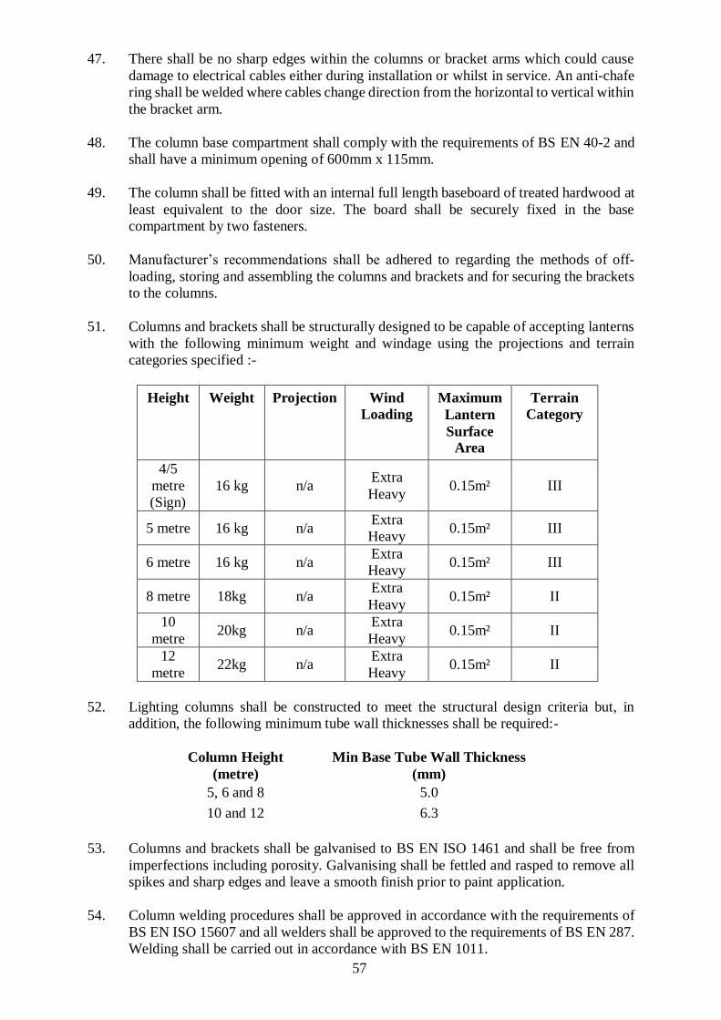
57
47. There shall be no sharp edges within the columns or bracket arms which could cause
damage to electrical cables either during installation or whilst in service. An anti-chafe
ring shall be welded where cables change direction from the horizontal to vertical within
the bracket arm.
48. The column base compartment shall comply with the requirements of BS EN 40-2 and
shall have a minimum opening of 600mm x 115mm.
49. The column shall be fitted with an internal full length baseboard of treated hardwood at
least equivalent to the door size. The board shall be securely fixed in the base
compartment by two fasteners.
50. Manufacturer’s recommendations shall be adhered to regarding the methods of off-
loading, storing and assembling the columns and brackets and for securing the brackets
to the columns.
51. Columns and brackets shall be structurally designed to be capable of accepting lanterns
with the following minimum weight and windage using the projections and terrain
categories specified :-
Height Weight Projection Wind
Loading
Maximum
Lantern
Surface
Area
Terrain
Category
4/5
metre
(Sign)
16 kg n/a Extra
Heavy 0.15m² III
5 metre 16 kg n/a Extra
Heavy 0.15m² III
6 metre 16 kg n/a Extra
Heavy 0.15m² III
8 metre 18kg n/a Extra
Heavy 0.15m² II
10
metre 20kg n/a
Extra
Heavy 0.15m² II
12
metre 22kg n/a
Extra
Heavy 0.15m² II
52. Lighting columns shall be constructed to meet the structural design criteria but, in
addition, the following minimum tube wall thicknesses shall be required:-
Column Height
(metre)
Min Base Tube Wall Thickness
(mm)
5, 6 and 8 5.0
10 and 12 6.3
53. Columns and brackets shall be galvanised to BS EN ISO 1461 and shall be free from
imperfections including porosity. Galvanising shall be fettled and rasped to remove all
spikes and sharp edges and leave a smooth finish prior to paint application.
54. Column welding procedures shall be approved in accordance with the requirements of
BS EN ISO 15607 and all welders shall be approved to the requirements of BS EN 287.
Welding shall be carried out in accordance with BS EN 1011.
58
55. Columns planting depths shall be indicated by a 25mm white band around the
circumference of the column and planting depths will be as follows:-
Column Height
(metre)
Planting Depth
(mm)
4 & 5 800
6 1000
8 1200
10 1500
12 1700
56. Columns shall have the following finished protection system:-
(a) Pre-treat galvanised internal surface of root to 250mm above ground level
and the whole of the external surface with Dacrylate “T” wash ref: 150-23
application to be applied fully in accordance with Dacrylate Technical Data
Sheet (Shop applied);
(b) Apply one coat of compliant Vinadac Micaceous Iron Oxide 45 Line to
internal/external surface of root to 250mm above ground level, minimum
dry film thickness 75 µm grey (Shop applied).
(c) Apply one coat of compliant Vinadac Micaceous Iron Oxide 45 Line to
external surface of column, minimum dry film thickness 75 µm grey (Shop
applied).
(d) Apply one coat of compliant Vinadac Sheen finish 45 Line to external
surface of root and upper section of column, minimum dry film thickness
75 µm colour to BS 10A07 steel grey (Shop applied).
(e) All coatings to external surfaces shall be airless sprayed.
(f) Alternative finishes may be acceptable but prior approval of Overseeing
Organisation must be given.
Column Data Sheet
57. A completed column data sheet (See Appendix 13/2) shall be submitted to
Aberdeenshire Council’s Roads Development Section prior to commencement of
installation of any columns.
58. Columns and brackets shall not be erected until Aberdeenshire Council’s Roads
Development Section has notified acceptance of the completed data sheet in writing to
the Developer.
Installation of Columns
59. Unless otherwise agreed by Aberdeenshire Council’s Roads Development Section
columns shall be erected such that an operator working at the base compartment faces

59
the oncoming traffic except where the column is to be against a wall or fence etc. in
which case the door should face outwards to facilitate access.
60. Until completion of the erection of the column the temporary transit packaging shall be
left in place as far as practicable to protect against damage to the surface protection
system.
61. Unpacked columns shall not be stored on ground which may cause abrasions and
scoring of their surface.
62. A layer of concrete mix ST5, 75mm thick, complying with BS 8500-2 shall be placed
and compacted in the bottom of the excavation up to the base of the column.
63. The cable entry slot shall be temporarily plugged as necessary in order to prevent any
ingress of concrete or filling material during the concreting and backfilling operations.
64. The hole into which the column is placed shall be backfilled with concrete mix ST5 well
compacted by vibration over the full planting depth of the column.
65. Columns shall be installed by hand or, where necessary, lifting equipment employing
fabric or non-abrasive straps. Chains shall not be used in the erection of the columns.
66. Where an obstruction is encountered necessitating a change in the agreed location of a
lighting unit the installation shall not commence until approval of the revised location
has been given by Aberdeenshire Council’s Roads Development Section.
67. Root protection shall be visible for approximately 250mm above finished ground level
when column erection is complete.
Identification
68. Aberdeenshire Council’s Roads Development Section shall provide details of
identification numbering to be applied by the Developer once road names have been
allocated.
69. Self-adhesive vinyl identification numbers, black number on white background 50mm
tall, shall be applied by the Developer to the columns at 2.5 metres above ground.
70. Numbers shall be applied such that they are at 45 degrees to, and facing, oncoming
traffic.
Overhead Power Lines
71. The Developer shall consult with the Electricity Supply Authority where columns are
to be erected in the vicinity of overhead power lines.
72. Written confirmation shall be provided to Aberdeenshire Council’s Roads Development
Section that agreement has been reached with the Electricity Supply Authority to the
proximity of columns to overhead lines.
60
Electrical Work – General
73. Materials equipment and workmanship shall comply with BS 7671 Requirements for
Electrical Installations (IET Wiring Regulations) and the rules and regulations of the
Electricity Supply Company.
74. The Developer shall adhere to Engineering Recommendation G39/1 “Model Code of
Practice covering Electrical Safety in the Planning, Installation, Commissioning and
Maintenance of Public Lighting and Other Street Furniture”.
75. The Developer shall also adhere to the requirements of the Electricity at Work
Regulations 1989.
76. The Developer shall employ only competent personnel each of whom holds a
“Competent Persons Authorisation Certificate” in accordance with the model form in
Appendix B of the above document G39/1.
77. Electrical equipment shall be installed so that levels of radio interference given in BS
EN 55014 are not exceeded.

61
APPENDIX 14/1: SITE RECORDS
1. As built drawings shall be produced by the Developer, on 3 number copies of the
Drawings relating to Road Lighting in accordance with the requirements of Clause
1402.
2. The Developer shall also supply test certificates cross-referenced to the apparatus
identified on the as-built drawings
APPENDIX 14/2: LOCATION OF LIGHTING UNITS AND FEEDER PILLARS
General
1. The position and description of Lighting Units and Feeder Pillars will be as shown on
the Consent Drawings.
2. The exact location of such equipment shall be agreed on site before commencement of
the works.
3. Where a feeder pillar is erected on a grass verge, an area of hard standing shall be
created in front of the pillar using a 900 x 600mm paving slab laid on a sand bed (or
equivalent) on 150mm of Type 1 sub-base.
Electricity Supply
4. Unless otherwise agreed by the Roads Authority’s Representative, the electricity
supply to the feeder pillars shall be single-phase 240 volt 50Hz.
APPENDIX 14/3: TEMPORARY LIGHTING
1. Where existing lighting units are temporarily taken out of service to facilitate a
Developers operations, then temporary lighting shall be provided, to a level agreed
with the Street Lighting Officer, for the safe passage of vehicles and pedestrians
adjacent to the site. Any costs associated with this provision shall be met by the
Developer.
APPENDIX 14/4: ELECTRICAL EQUIPMENT FOR ROAD LIGHTING
General
1. All lamps shall be LED units and have a minimum guaranteed life of 50,000 hours.
2. All lanterns shall be compatible with the columns and brackets used.
3. Lanterns shall comply with BS EN 60598-2-3.
4. Lanterns shall have a minimum degree of protection rating IP 65 to BS EN 60529.

62
5. Unless otherwise agreed by the Roads Authority’s Representative, all lanterns shall be
of a type incorporating integral electronic lamp control gear mounted on a removable
gear tray.
6. Plug-in type gear trays shall be used and shall have a fuse holder adjacent to the terminal
block with a cartridge fuse protecting the control gear.
7. Control gear for use with all new installations shall be of a one piece electronic type and
be suitable for use in exterior lantern applications.
8. Electronic control gear shall be manufactured in accordance with BS EN 61000-3-2, BS
EN 61347-2-12, BS EN61000-3-3, BS EN 61547.
Installation of Lanterns
9. Lanterns shall be securely fixed to columns or brackets in compliance with
manufacturers’ instructions.
10. Wiring between lanterns and cut-out unit in column base compartment shall be by
means of blue sheathed Arctic flexible cable.
11. Wiring conductor size shall be 1.5 sq mm 3 core cable incorporating phase, neutral and
earth conductors.
Cable Cut-outs
12. Cut-out enclosures shall be suitable for fixing in a lighting column base compartment
and accommodate termination of up to 3 No. PVC/SWA/PVC cables of maximum size
25 sq mm 3-core supplying one or two outgoing 2.5 sq mm maximum lamp circuits, as
required, via circuit protection MCB(s).
13. Cut-out units shall incorporate a double-pole switching device configured to isolate all
circuits emanating from the cut-out.
14. The cut-out manufacturer shall be accredited to BS EN ISO 9001 by an accredited
certification body.
15. The design and construction of cut-out units shall ensure that in normal use it will
function in a reliable manner and cause no danger to persons or adjacent equipment. It
shall be impact resistant and shall be constructed such that it cannot readily be deformed
or mechanically damaged allowing contact with live parts.
16. Cut-out units shall allow ease of access to internal terminations with all separable parts
having a positive location arrangement. Removable parts shall be such that they cannot
be separated from the unit except by use of a key or tool.
17. Cut-out units shall be rated at 240 Volts, 40 Amps and shall comply with BS EN:60947-
1 Specification, and when correctly installed shall comply with BS 7671 and provide a
degree of protection as specified in BS EN 60529 to category IP 42.
18. Cable entry shall be by means of a removable brass earth plate, of minimum thickness
2.5mm, with three 25mm diameter ferrules to accept armour wires. Armour wires shall
be terminated in stainless steel worm drive clamps. The plate shall be complete with
one M6 min. earth stud with fitting and locking arrangement to allow connection of
63
crimped terminals on protective and extraneous bonding conductors, both externally
and internally.
19. Terminals shall consist of a 40mm X M6 stud suitable for use with compression cable
connectors, complete with lock-nuts, washers and spacers sufficient to allow
termination of one to three cables as appropriate.
20. Phase, neutral and earth terminals shall be provided and the earth terminal shall be
linked to the brass earth plate by a green/yellow conductor equivalent to 10 sq mm tri-
rated cable. The unit shall be capable of accommodating an additional terminal block
(i.e. 4 No. in total) and capacity for 3 No. MCB’s mounted on DIN rail with blanking
pieces as necessary where this option has not been taken up.
21. The approximate dimensions of cut-out units shall be as follows:-
Height 390mm
Width 88mm
Depth 92mm
22. All materials used in the construction of the unit shall comply with the relevant British
or European Standards and current carrying parts shall be manufactured in brass, copper
or phosphor bronze and shall be electroplated.
23. Cable core connections shall be as follows :-
Phase connection BROWN
Neutral connection BLUE
Earth connection GREEN/YELLOW
Installation of Cable Cut-out Units
24. Cut-out units shall be secured to the backboard in the column base compartment such
that it will not be fouled by the door locking mechanism.
25. After installation it shall be possible to access the cable armour clamps and all cut-out
cover screws for maintenance purposes.
26. Completed cut-out after installation shall be as shown on Construction Detail Drawing.
Feeder Pillars
27. Feeder Pillars and internal distribution panels shall be manufactured to comply with BS
EN 61439 and tested and certified accordingly.
28. Feeder Pillar shell shall be constructed of hot-dip galvanised or stainless steel, having a
minimum wall thickness of 3mm, and shall have dimensions as detailed on the
Construction Detail Drawing.
29. Feeder pillar door locking shall be by means of wedge type “O” Ring locks, both of
which can be operated by a single key.

64
30. The pillar door shall be provided with a means of fitting a padlock to prevent
unauthorised access.
31. Pillars shall be finished in Dawn Grey (10 A 03 to BS 4800)
32. Distribution panels as detailed on the Construction Detail Drawing shall be fitted in
feeder pillars.
Installation of Feeder Pillars
33. Where a feeder pillar is erected on a grass verge an area of hardstanding shall be created
at the pillar door using a 900 x 600mm paving slab or equivalent.
Underground and Ducted Cables
34. Cables shall have XLPE insulation and XLPE or MDPE sheathing, PURPLE in colour.
They shall be 600/1000 Volt grade with steel wire armouring to BS 5467 and all
conductors shall be of equal cross-sectional area. The Developer shall provide to
Aberdeenshire Council’s Roads Development Section evidence that each cable length
delivered has been tested at the place of manufacture and complies with the
requirements of BS 5467 according to the cable used.
35. The cable shall have BASEC or HAR approval in all respects other than the oversheath
colour which shall be PURPLE.
36. Cables will normally be 3 core in the range 2.5, 6.0, 16.0 and 25.0 sq mm. Cable
sheaths shall have meterage marked at 1 metre intervals along their total length.
37. Where a lighting column or feeder pillar is to be joined directly to the Electricity
Authority’s mains network the service cable shall be to the requirements of the
Electricity Authority.
38. Cables shall employ a loop-in/loop-out system between lighting units and no joints shall
be permitted on the underground cabling system
39. Lighting cables shall be enclosed in ducts.
40. Ducts shall be 100mm internal diameter UPVC and be PURPLE in colour. They shall
be jointed in such a manner as to preclude ingress of solid material.
41. All cables and ducts shall have a suitable marker tape laid directly above them at a
position 150mm below ground.
42. Cable marking tape shall be purple heavy gauge PVC or polythene plastic tape, 150mm
wide and not less than 0.1mm thick with a tensile strength as follows:-
Machine direction 2200-2400 p.s.i.
Transverse Direction 2000-2200 p.s.i.
The tape shall carry in bold black letter along its full length, occupying not less than
75% of its available length and occurring at least at 1 metre intervals, the repeated
message:-
65
CAUTION
STREET LIGHTING CABLE BELOW
Cable Installation
43. Cable trenches shall be excavated to the lines shown on the contract drawings. The depth
of excavation shall be such that cables laid under verges, footways or open ground shall
have a minimum cover of 450mm and under carriageways a minimum cover of 750mm.
44. Cables shall be laid without sharp bends or kinks and shall not be bent to an internal
radius of less than 12 times the external diameter of the cable or less than the radius
recommended by the manufacturer, whichever is greater.
45. Sufficient length of cable shall be allowed for its termination. If termination does not
proceed immediately following installation of the cable, its ends shall be sealed against
the ingress of moisture.
46. When duct alignments differ from those of the trench the transition from one to the other
shall not exceed 1:30 horizontally or vertically.
47. The Developer shall swab through the duct prior to drawing in the cables and a further
draw rope. On completion of the cabling, ducts shall be left with a draw rope in place.
48. Backfilling and reinstatement to cable trenches shall comply with the current edition of
the “New Streets and Road Works Act 1991”, “Specification for the Reinstatement of
Openings in Roads” and to the requirements of Appendix 7/2
Photo-Electric Control Units
49. Photo-electric cell units shall be fully electronic incorporating a solid state switching
circuit with zero crossover.
50. The classification of the Photo Control, with reference to protection against electric
shock, shall be Class 2 and to IP 65 of BS EN 60529.
51. The Photo Controls shall comply with all European directives and regulations on Electro
Magnetic interference.
52. All components used in the Photo Control shall be capable of operating within the
temperature range of -20oC to + 80oC.
53. Photo-electric cell units shall be of three types as follows:-
(i) ONE-PART UNIT – in which the photo-electric sensor and the load switching
components are housed in the same enclosure, suitable for insertion into a
“NEMA” type socket to obtain mechanical and electrical connection.
(ii) TWO-PART UNIT – in which the photo-electric sensor and the load switching
components are housed in separate enclosures. The photo-electric sensor in its
housing shall be suitable for direct mounting to luminaire canopies or other
equipment by means of mechanical screwed fixing.
66
(iii) ONE-PART MINIATURE – in which the photo-electric sensor and the load
switching components are housed in the same enclosure. The enclosure shall be
suitable for direct mounting to luminaire canopies or other equipment by means
of a 20mm threaded conduit fixing complete with rubber seals, plastic washers,
locknuts and cable tails, suitable for hard-wiring to the lamp circuit.
54. One-Part Miniature photo-electric units shall be utilised on all lighting units unless
otherwise requested by Aberdeenshire Council’s Roads Development Section, except
where the lighting unit is linked to a feeder pillar panel in which case it shall be of the
Two-Part type.
55. The cone should have a smooth finish and be shaped such that it is self-cleaning. It
shall be capable of sustaining the impact test set out in BS EN 60598-2-22 as BS 5972
refers.
56. Plastic materials used in the Photo Control shall be flame retardant in accordance with
BS EN 60598-2-22.
57. The complete Photo Control shall be capable of withstanding shock and vibration as
prescribed in BS EN 60068-1.
58. The Photo Control shall be suitable for use on 230V +10% -6% 50Hz. It shall be capable
of switching a reactive lighting load of 10 Amperes. The unit shall have no thermal
switching components. The average daily power consumption of the Control shall not
exceed 1 watt. The switching device shall be capable of performing not less than 3000
operations at rated load under normal operating conditions.
59. In no part of the Control shall material capable of deforming as a result of the working
environment be sandwiched between electrical connections.
60. Sockets for one-part Photo Controls shall comply in all respects with the requirements
of BS EN 12209. A sealing gasket shall be provided between the socket and the lantern
enabling the socket to be fitted to the curved surface of the lantern body. Sealing gaskets
shall also be provided between the Photo Control and the socket providing protection to
IPX4 of BS EN 60529. Gaskets shall be of materials which will not deteriorate in
normal service. They shall ensure dustproof and waterproof joints between Photo
Control and socket and between socket and lantern. The gasket material shall be an
EPDM Neoprene Polymer capable of operating over the temperature range -56o to + 90o
with a flammability rating of MVSS-02. Good resistance to weathering, ozone and ultra
violet radiation is essential.
61. The sensor shall be either Photo Diode or Photo Transistor and have an MTBF (mean
time between failures) of at least 1 million hours and shall be fitted with an optical filter
spectrally matched to the CIE photopic curve.
62. Calibration of the unit shall be carried out to provide levels 35 Lux ON and 18 Lux OFF
to a measuring accuracy of +/-5% in artificial light. The set switching level shall be
maintained over the guaranteed life of the control.
63. The Supplier shall be required to guarantee all controls electrically, mechanically and
photometrically for a period of 6 years
64. All PECU’s shall indicate the year and month of manufacture and incorporate a simple
method of recording the date of installation by the Developer.

67
68
Earthing
65. The brass earth plate on the cable cut-out unit shall be bonded to the earth stud within
the column base using a braided copper earth strap. Similarly, the column door shall be
bonded to the earth stud in the column base.
66. The braided copper earth straps to be used for this purpose shall be 750mm long and be
equivalent to a cable cross-section of 10 sq mm. They shall be sleeved in a green/yellow
insulating material and have crimped lugs at each end suitable to fit an 8mm earth stud.
67. All lanterns shall be earthed to the cut-out unit earth terminal via the 3 core ARCTIC
flex installed within the column.
Safe Working
68. Prior to commencing work on any electrical network, connected with road lighting or
traffic signs/bollards, the Developer shall confirm with Aberdeenshire Council’s Roads
Development Section, and by test, the origin of the electrical supply to that network.
69. The main switch in the feeder pillar, supplying the network, shall be switched “OFF”
and a warning notice, as described in the construction Details Drg. K88, shall be posted
at the switch, to the effect that personnel are working on the circuit.
70. The warning notice referred to above, shall be displayed such that it is clearly seen by
any persons, on opening the feeder pillar door.
71. “LIVE” working on alterations to existing equipment, or installation of new equipment,
shall not be permitted except where live testing is being carried out in compliance with
Clause 1424.
72. On completion of work on the network, the Developer shall physically check the circuit,
to ensure that his personnel, and any other parties, are clear, prior to switching on the
main switch and removing the warning notice.
Electrical Inspection and Testing
73. The electrical installation and equipment shall be inspected and tested in accordance
with Part 6 of BS 7671:2008, the IET Wiring Regulations (17th Edition).
74. The following tests shall be carried out in the sequence indicated and be recorded on the
certificate LTG001 contained in this document and submitted to Aberdeenshire
Council’s Roads Development Section on completion of the installation:
(a) Initial verification/visual inspection
(b) Continuity of protective conductors including main and supplementary
equipotential bonding
(c) Insulation resistance at a test voltage of 250 Volts to be not less than 0.5
MΩ
(d) Insulation resistance at a test voltage of 500 Volts to be not less than 1.0
MΩ
(e) Insulation of site-built assemblies
(f) Polarity, including the continuity of circuit conductors
(g) Earth fault loop impedance at every cut-out
(h) Earth electrode resistance (where applicable)
69
(i) Operation of residual current devices (where applicable)
(j) Voltage and/or Volts drop
75. Standard methods of testing are given in the current edition of BS 7671 Requirements
for Electrical Installations.
76. Tests for fixed equipment including lighting columns, traffic signs, bollards, pedestrian
refuge and/or crossing globes, feeder pillars and any other electrical installations on
roads specified by Aberdeenshire Council’s Roads Development Section, shall be as
follows:- (a), (b), (c), (e), (f), (g), (h), (I), (j).
77. Tests for cable networks shall be as follows:- (a), (b), (d), (f), (g), (j).
78. Voltage/Volt drop readings on cable networks shall be taken under full load conditions
with all equipment energised (and fully “run up”).
79. The Developer shall give not less than 7 days’ notice to Aberdeenshire Council’s Roads
Development Section of his intention to carry out any of the tests specified and
Aberdeenshire Council’s Roads Development Section shall be given the opportunity to
witness such tests.
APPENDIX 14/5: ELECTRICAL EQUIPMENT FOR TRAFFIC SIGNS
General
1. Traffic signs shall generally comply with the requirements of appendix 14/1 and 14/4.
2. The Developer shall submit to the Roads Development Engineer details of the units he
proposes to use for the lighting of the traffic signs.
3. Signs shall only be lit where this is a mandatory requirement of the Traffic Signs
Regulations and General Directions.
Lighting of Traffic Signs
4. Signs to be lit by LED lantern to recommended levels.
Column Base Cable Termination
5. Traffic column base cable terminations shall comply with Appendix 14/4 and be either
looped on single circuit, complying with Drawing K83 and K84.

70
Form LTG001
INSTALLATION INSPECTION & TEST CERTIFICATE
Sheet 1
ITEMS INSPECTED PASS FAIL NOT
APPLICABLE
1. Connections of conductors
2. Identification of conductors
3. Selection of conductors for current carrying capacity
4. Connection of single pole devices in phase conductors only
5. Correct connection of lampholders and socket outlets
6. Protection against thermal effects
7. Methods of protection against direct contact
8. Appropriate isolation and switching devices
9. Appropriate protective devices
10. Labelling of circuits etc.
11. Selection of equipment for environmental conditions
12. Presence of warning and danger notices where appropriate
13. Presence of diagrams, instructions, etc.
14. Conditions of flexible cables, switching, plugs and sockets outlets
The following shall be tested, in the sequence indicated, and if any test indicates failure to comply, that test and those preceding shall be repeated in the correct sequence, after the fault has been rectified.
15. The continuity of protective conductors, including main and supplementary equipotential bonding (Regulation 612.2.1)
16. The continuity of final circuit conductors (Regulation 612.2.2)
17. Insulation resistance, which should not be less than 1 MΩ for fixed installations and not less than 0.5 MΩ for separate items of apparatus (Regulation 612.3)
18. Protection by enclosures, which shall afford a degree of protection not less than IP2X (Regulation 612.4)
19. Polarity (Regulation 612.6)
20.
The earth fault loop impedance, which should be satisfactory for ready operation of protective devices in compliance with regulations 411 (Regulation 612.7) Values of earth loop impedance for each circuit should be noted on Sheet 2 of this certificate.
21. The operation of residual current devices tested independently of any facilities incorporated in the device (Regulation 612.11)

71
INSTALLATION INSPECTION & TEST CERTIFICATE
Sheet 2
Circuit No.
Protective
Device
Insulation
Resistance
Earth fault loop
impedance
Voltage
Source Remote End
1.
2.
3.
4.
5.
6.
7.
8.
Comments (if any) and departures from the Wiring Regulations :
This Inspection and Test Certificate is to be signed by the Contractor or other person responsible for carrying out an inspection and test of an installation, or part of an installation, or by a person acting on his behalf.
I certify that the electrical installation at:-
has been inspected and tested in accordance with the requirements of Part 6 of BS7671:2008, the IET Regulations for Electrical Installations (17th Edition) and that the results are as indicated on Sheets 1 and 2 of this certificate.
Signed: Date:
For and on behalf of:
Address:
______________________________________________________________
72
APPENDIX 30/4: GROUND PREPARATION
1. Where the ground is required to lie for a period of time before sowing the Developer
will use a Glyphosate chemical weedkiller to kill existing weeds etc.
2. 150mm of good quality vegetable top soil shall be spread over the site and levelled.
The finished level of the soil shall be 25mm above kerbs, paving or manhole covers.
3. The ground shall be cultivated to a depth of 150mm removing stones and debris over
25mm in size within the top 50mm of the topsoil. After the completion of the
cultivation the Developer shall produce a seed bed of a fine tilth and even level to act
as a seed bed.
4. Where areas are to be planted with shrubs etc. the ground shall be cultivated to a depth
of 300mm removing stones and debris over 50mm in size prior to planting.
APPENDIX 30/5: GRASS SEEDING, WILDFLOWER SEEDING AND TURFING
Grass Seed
1. Grass seed shall be a tested mixture from an approved source and certificates of purity
and germination shall be provided. All varieties of grass used shall be dwarf turf type
cultivars currently listed by the Sports Turf Research Institute, Bingley. Unless
otherwise agreed by the Roads Development Engineer the mixture shall consist of the
flowing mixture (or equivalent) parts by mass as specified in Table 30/5 below.
2. The seed bed shall be fine, smooth and evenly formed but not over consolidated. All
surplus vegetable matter, stones 25mm or over and foreign material shall be
collected and removed off site to a tip. The grass seed will be sown evenly over the
site; afterwards the seed will be lightly harrowed into the surface. Thereafter, the
area will be racked to remove foreign matter, stones over 25mm in size brought up
by the harrow. These shall be collected and removed off site to a tip by the
Developer.
3. Sowing of grass seed will generally be carried out during the season from 1 May to
30 September. The Developer will pay due regard to the weather conditions before
sowing grass seed and shall take all reasonable measures to promote its growth.
Immediately prior to seeding the Developer shall treat any undesirable vegetation
using a weed-killer specifically formulated to eradicate this vegetation.
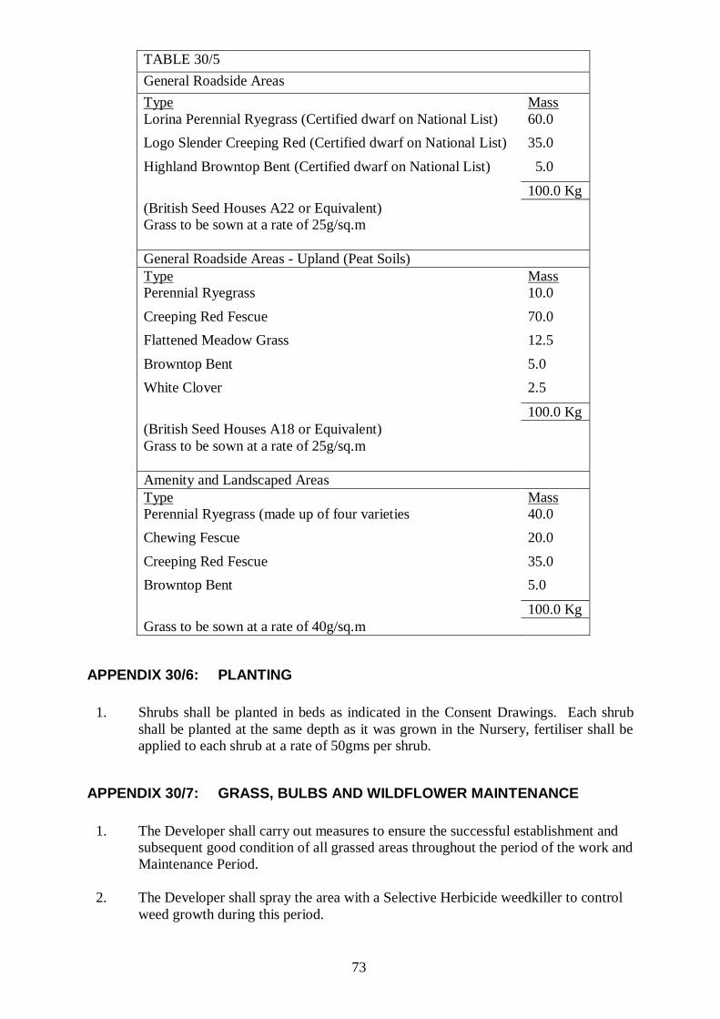
73
TABLE 30/5
General Roadside Areas
Type Mass
Lorina Perennial Ryegrass (Certified dwarf on National List) 60.0
Logo Slender Creeping Red (Certified dwarf on National List) 35.0
Highland Browntop Bent (Certified dwarf on National List) 5.0
100.0 Kg
(British Seed Houses A22 or Equivalent)
Grass to be sown at a rate of 25g/sq.m
General Roadside Areas - Upland (Peat Soils)
Type Mass
Perennial Ryegrass 10.0
Creeping Red Fescue 70.0
Flattened Meadow Grass 12.5
Browntop Bent 5.0
White Clover 2.5
100.0 Kg
(British Seed Houses A18 or Equivalent)
Grass to be sown at a rate of 25g/sq.m
Amenity and Landscaped Areas
Type Mass
Perennial Ryegrass (made up of four varieties 40.0
Chewing Fescue 20.0
Creeping Red Fescue 35.0
Browntop Bent 5.0
100.0 Kg
Grass to be sown at a rate of 40g/sq.m
APPENDIX 30/6: PLANTING
1. Shrubs shall be planted in beds as indicated in the Consent Drawings. Each shrub
shall be planted at the same depth as it was grown in the Nursery, fertiliser shall be
applied to each shrub at a rate of 50gms per shrub.
APPENDIX 30/7: GRASS, BULBS AND WILDFLOWER MAINTENANCE
1. The Developer shall carry out measures to ensure the successful establishment and
subsequent good condition of all grassed areas throughout the period of the work and
Maintenance Period.
2. The Developer shall spray the area with a Selective Herbicide weedkiller to control
weed growth during this period.

74
Grass Cutting
3. When the grass is 30-40mm long it shall be inspected and the Developer will remove
all surface stones which have a dimension of 25mm or more, together with any
foreign material.
4. The Developer will be responsible for cutting the grass during the period of the
works and throughout the Maintenance Period. During the cutting season the first
cut shall be made when the grass is 50mm high and after this cut the grass shall be
no longer than 25mm high. Thereafter the grass shall be cut regularly so that at no
time does it exceed 60mm in height.
5. Grassed area will be accepted as reaching practical completion only when
germination has proved satisfactory and the grass is showing an even sward.
The Developer shall remove and replace any areas which are not in a healthy
condition.