Embed Size (px)
Citation preview

PRECAST CONCRETEBARRIER CRASH TESTING
Final Report
SPR 330


PRECAST CONCRETE BARRIER CRASH TESTING
Final Report
SPR 330
by
Daniel J. MacDonald, Standards EngineerRoadway Engineering Section
ODOT Highway Division
and
Alan R. Kirk, Research AnalystResearch Group
ODOT Transportation Development Division
for
Oregon Department of TransportationResearch Group
200 Hawthorne SE, Suite B-240Salem OR 97301-5192
and
Federal Highway AdministrationWashington, D.C.
December 2001


i
Technical Report Documentation Page1. Report No.
FHWA-OR-RD-02-07
2. Government Accession No. 3. Recipient’s Catalog No.
5. Report Date
December 2001
4. Title and Subtitle
Precast Concrete Barrier Crash Testing - Final Report
6. Performing Organization Code
7. Author(s)
Daniel J. MacDonald, Standards Engineer (Principal Investigator)Roadway Engineering Section, ODOT Highway DivisionandAlan R. Kirk, Research AnalystResearch Group, ODOT Transportation Development Division
8. Performing Organization Report No.
10. Work Unit No. (TRAIS)9. Performing Organization Name and Address
Oregon Department of TransportationResearch Group200 Hawthorne Ave. SE, Suite B-240Salem, OR 97301-5192
11. Contract or Grant No.
SPR 330
13. Type of Report and Period Covered
Final Report
12. Sponsoring Agency Name and Address
Oregon Department of Transportation Federal Highway AdministrationResearch Group and 400 Seventh Street SW200 Hawthorne Ave. SE, Suite B-240 Washington, DC 20590Salem, OR 97301-5192
14. Sponsoring Agency Code
15. Supplementary Notes
16. Abstract
The objectives of this project were to crash test the Oregon Standard (32-inch) F-shape precast concrete barrier andthe Oregon Tall (42-inch) F-shape precast concrete barrier against the new NCHRP Report 350 standards, toensure compliance of these safety systems. FHWA has required that such systems are acceptable under NCHRPstandards by no later than October 2002. The results of the Test Level 3 crash tests showed that both barriers meetNCHRP requirements. Furthermore, FHWA acknowledged both barriers as having the best performance of anyfree-standing precast concrete barriers to date. The research report also discusses the performance of the Tall F-shape barrier in a Test Level 4 crash test, involving an 8,000 kg single-unit truck. The barrier passed this test aswell.
17. Key Words
precast concrete barrier, temporary concrete barrier, medianbarrier, crash test, NCHRP Report 350
18. Distribution Statement
Available from NTIS and fromOregon Department of Transportation(http://www.odot.state.or.us/tddresearch)
19. Security Classification (of this report)
Unclassified
20. Security Classification (of this page)
Unclassified
21. No. of Pages
27 + appendices
22. Price
Technical Report Form DOT F 1700.7 (8-72) Reproduction of completed page authorized � Printed on recycled paper

ii
SI* (MODERN METRIC) CONVERSION FACTORSAPPROXIMATE CONVERSIONS TO SI UNITS APPROXIMATE CONVERSIONS FROM SI UNITS
Symbol When You Know Multiply By To Find Symbol Symbol When You Know Multiply By To Find Symbol
LENGTH LENGTH in inches 25.4 millimeters mm mm millimeters 0.039 inches in ft feet 0.305 meters m m meters 3.28 feet ft yd yards 0.914 meters m m meters 1.09 yards yd mi miles 1.61 kilometers km km kilometers 0.621 miles mi
AREA AREA in2 square inches 645.2 millimeters squared mm2 mm2 millimeters squared 0.0016 square inches in2
ft2 square feet 0.093 meters squared m2 m2 meters squared 10.764 square feet ft2
yd2 square yards 0.836 meters squared m2 ha hectares 2.47 acres ac ac acres 0.405 hectares ha km2 kilometers squared 0.386 square miles mi2
mi2 square miles 2.59 kilometers squared km2 VOLUMEVOLUME mL milliliters 0.034 fluid ounces fl oz
fl oz fluid ounces 29.57 milliliters mL L liters 0.264 gallons gal gal gallons 3.785 liters L m3 meters cubed 35.315 cubic feet ft3
ft3 cubic feet 0.028 meters cubed m3 m3 meters cubed 1.308 cubic yards yd3
yd3 cubic yards 0.765 meters cubed m3 MASSNOTE: Volumes greater than 1000 L shall be shown in m3. g grams 0.035 ounces oz
MASS kg kilograms 2.205 pounds lb oz ounces 28.35 grams g Mg megagrams 1.102 short tons (2000 lb) T lb pounds 0.454 kilograms kg TEMPERATURE (exact) T short tons (2000 lb) 0.907 megagrams Mg �C Celsius temperature 1.8C + 32 Fahrenheit �F
TEMPERATURE (exact)
�F Fahrenheittemperature
5(F-32)/9 Celsius temperature �C
* SI is the symbol for the International System of Measurement (4-7-94 jbp)

iii
ACKNOWLEDGEMENTS
The following people served on the Technical Advisory Committee for this project: Mike Harris,Larry Christianson, and Alan Kirk from ODOT; and Victoria Kinne and Jeff Graham fromFHWA. Discussion and analysis of the findings were also handled by the ODOT Tall BarrierDesign Team: Dan MacDonald, Mike Harris, Terry Wheeler, Sam Grossberg, John Lucas, andDerryl James. For help and guidance in contracting, much appreciation goes to Dan Butcher,Contract Coordinator, ODOT Purchasing and Contract Management Section. Thanks also toDick Powers and Charles McDevitt at FHWA for their guidance in this project.
DISCLAIMER
This document is disseminated under the sponsorship of the Oregon Department ofTransportation and the U.S. Department of Transportation in the interest of informationexchange. The State of Oregon and the U.S. Government assumes no liability of its contents oruse thereof.
The contents of this report reflect the views of the author(s) who are solely responsible for thefacts and accuracy of the material presented. The contents do not necessarily reflect the officialviews of the Oregon Department of Transportation or the U.S. Department of Transportation.
The State of Oregon and the U.S. Government do not endorse products or manufacturers.Trademarks or manufacturer’s names appear herein only because they are considered essential tothe object of this document.
This report does not constitute a standard, specification, or regulation.


v
PRECAST CONCRETE BARRIER CRASH TESTING
TABLE OF CONTENTS
1.0 INTRODUCTION..................................................................................................................11.1 BACKGROUND .................................................................................................................11.2 OBJECTIVES OF THE STUDY.........................................................................................2
2.0 RESEARCH METHODS......................................................................................................32.1 CRASH TESTING CRITERIA ...........................................................................................32.2 CRASH TESTS ...................................................................................................................42.3 SELECTION OF CRASH TESTING FACILITIES ...........................................................5
3.0 RESULTS AND DISCUSSION ............................................................................................73.1 CRASH TEST 1 - STANDARD F-SHAPE BARRIER......................................................73.2 CRASH TEST 2 - TALL F-SHAPE BARRIER..................................................................93.3 CRASH TEST 3 - SECOND TEST OF THE TALL F-SHAPE BARRIER .....................11
4.0 DISCUSSION AND CONCLUSIONS ...............................................................................154.1 NCHRP REQUIREMENTS ..............................................................................................154.2 DESIGN CONSIDERATIONS .........................................................................................154.3 CONCLUSION..................................................................................................................16
5.0 REFERENCES.....................................................................................................................17
APPENDICES
APPENDIX A: DESIGN SPECIFICATIONS FOR THE STANDARD F-SHAPEPRECAST CONCRETE BARRIER
APPENDIX B: DESIGN SPECIFICATIONS FOR THE TALL F-SHAPE PRECASTCONCRETE BARRIER
APPENDIX C: KARCO ENGINEERING TEST LEVEL 3 CRASH TEST REPORTFOR STANDARD F-SHAPE CONCRETE BARRIER (EXCERPT)
APPENDIX D: KARCO ENGINEERING TEST LEVEL 3 CRASH TEST REPORTFOR TALL F-SHAPE CONCRETE BARRIER (EXCERPT)
APPENDIX E: KARCO ENGINEERING TEST LEVEL 4 CRASH TEST REPORTFOR TALL F-SHAPE CONCRETE BARRIER (EXCERPT)

vi
LIST OF TABLES
Table 3.1: Crash Test 1 results - Standard F-shape barrier and 2,000 kg truck ...................................................8Table 3.2: Crash Test 2 results - Tall F-shape barrier and 2,000 kg truck...........................................................10Table 3.3: Crash Test 3 results - Tall F-shape barrier and 8,000 kg truck...........................................................12
LIST OF FIGURES
Figure 1.1: Standard F-shape precast concrete barrier...................................................................................................1Figure 1.2: Tall F-shape precast concrete barrier ..........................................................................................................2Figure 3.1: Test vehicle prior to Crash Test 1, showing angle of impact ......................................................................7Figure 3.2: Standard F-shape barrier following Crash Test 1........................................................................................8Figure 3.3: Test vehicle prior to Crash Test 2, showing angle of impact ......................................................................9Figure 3.4: Tall F-shape barrier following Crash Test 2..............................................................................................10Figure 3.5: Test vehicle prior to Crash Test 3, showing angle of impact ....................................................................11Figure 3.6: Tall F-shape barrier following Crash Test 3..............................................................................................12

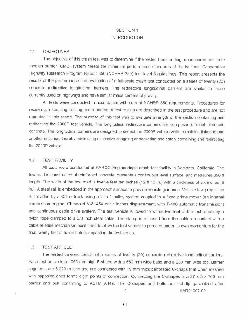
1
1.0 INTRODUCTION
1.1 BACKGROUND
The National Cooperative Highway Research Program (NCHRP) has established acomprehensive set of standards and procedures for evaluating the performance of permanent andtemporary highway safety features in Report 350, “Recommended Procedures for the SafetyPerformance Evaluation of Highway Features” (Ross, et al. 1993). The Federal HighwayAdministration (FHWA) has required that by no later than October 2002, states must confirmthat their safety features are acceptable under these new standards.
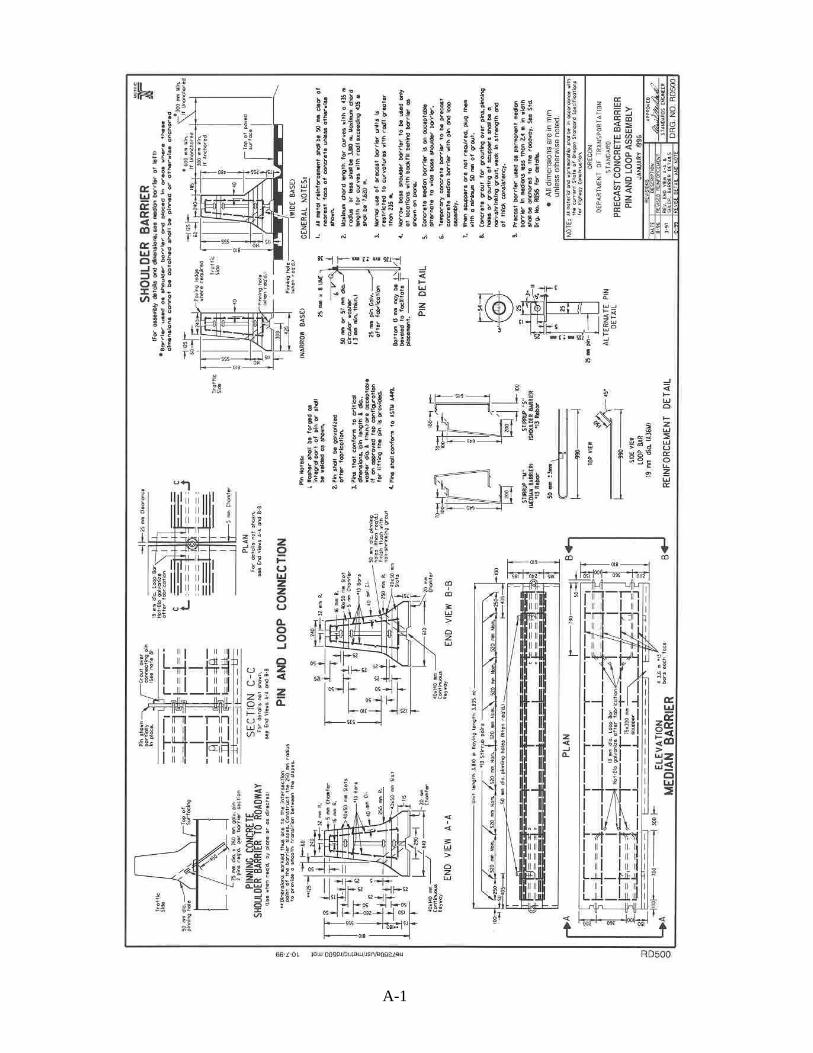
The Oregon Department of Transportation (ODOT) has been using a “Standard F-shape” precastconcrete barrier – 810 mm (32 in) in height – along its highways for many years. Approximately322 km (200 mi) of the current design of barrier are in use. Each barrier section is 3.81 m (12.5ft) in length. The barrier sections are held together with a pin and steel bar loop assembly.Figure 1.1 shows the Standard F-shape barrier. The specifications for this barrier are included inAppendix A.
Figure 1.1: Standard F-shape precast concrete barrier
In addition, ODOT recently adopted a “Tall F-shape” precast concrete barrier for use onhighways which carry large volumes of trucks. The higher barrier – 1065 mm (42 in) in height –is intended to provide more safety on the roadway, by better managing the impact of largervehicles than the smaller barrier. Each barrier section is 3.0 m (10 ft) in length. The barriersections are held together with a 25 x 760 mm (1 x 30 in) bolt and perforated C-shape assembly.Figure 1.2 shows the Tall F-shape barrier. The specifications for this barrier are included inAppendix B.

2
Figure 1.2: Tall F-shape precast concrete barrier
The shape of the concrete barrier was not in question. Both the Standard F-shape and Tall F-shape barriers were acceptable systems under NCHRP Report 350 when cast-in-place(permanent installation). In Oregon, however, the contractor is permitted to select either cast-in-place or precast sections. The trend has been for contractors to choose the less expensive precastoption. Thus crash testing of both the Standard F-shape and Tall F-shape precast barrier systemswas necessary under FHWA requirements to determine whether they would meet the NCHRPReport 350 standards.
1.2 OBJECTIVES OF THE STUDY
The objectives of this project were to crash test the Oregon Standard F-shape precast concretebarrier and the Oregon Tall F-shape precast concrete barrier against the new NCHRP Report 350standards, to ensure compliance of these safety systems.

3
2.0 RESEARCH METHODS
2.1 CRASH TESTING CRITERIA
NCHRP Report 350 provides a variety of standard crash testing procedures for concrete barriersand criteria for evaluating the results of the tests (Ross, et al. 1993). FHWA specified that a TestLevel 3 crash test – Test Designation 3-11 – must be performed on both the Standard F-shapeand the Tall F-shape barriers. This test calls for crashing a 2,000 kg (4,400 lb) pickup truck intothe barrier at 100 km/hr (62 mph), at an angle of 25 degrees from parallel. A total length of 61 m(200 ft) of barrier is required for the test, with the vehicle impact occurring approximately at themiddle of the run. The evaluation criteria for this test are as follows (Ross, et al. 1993):
“A. Test article should contain and redirect the vehicle; the vehicle should not penetrate,underride or override the installation, although controlled lateral deflection of the testarticle is acceptable.
D. Detached elements, fragments or other debris from the test article should not penetrate orshow potential for penetrating the occupant compartment, or present an undue hazard toother traffic, pedestrians or personnel in a work zone. Deformations of, or intrusionsinto, the occupant compartment that could cause serious injuries should not be permitted.
F. The vehicle should remain upright during and after collision, although moderate roll,pitching and yawing are acceptable.
K. After collision it is preferable that the vehicle’s trajectory not intrude into adjacent trafficlanes.
L. The occupant impact velocity in the longitudinal direction should not exceed 12 m/sec,and the occupant ridedown acceleration in the longitudinal direction should not exceed 20Gs.
M. The exit angle from the test article preferably should be less than 60 percent of the testimpact angle, measured at time of vehicle loss of contact with test device.”
In addition to these criteria, ODOT has established its own requirement concerning deflection ofthe barrier from an impact by a vehicle. ODOT specifies that the barrier does not need to beanchored to the roadway if there is at least 914 mm (36 in) of flat area behind the barrier fordeflection, with 600 mm (24 in) of this area paved. If there is not the required space behind thebarrier for deflection, ODOT requires the system to be anchored to the roadway. Each barriersection has openings to accommodate two 25 x 760 mm (1 x 30 in) galvanized pins foranchoring the section to roadway. These pins are placed 405 mm (15.9 in) from each end of thesection and angled at 54 degrees from the horizontal through the base of the barrier.
4
Thus ODOT was interested to know how each type of barrier performed in terms of deflection aswell as in terms of the NCHRP criteria. If either the Standard or the Tall barrier were deflectedmore than 914 mm (36 in), then anchoring it to the roadway would have to be considered inlocations where it was not currently required.
2.2 CRASH TESTS
The crash tests were planned as follows:
Crash Test 1. Crash test of the Standard F-shape barrier, not anchored to the roadway
If the barrier does not pass the crash test, the principal investigator will analyze theresults with the testing facility to determine the nature of the failure.
1. If the pin and loop connection between barrier sections contributed to the failure,the connection will be modified to strengthen it, and another test will beconducted.
2. If deflection of the barrier contributed to the failure, or if the barrier was deflectedmore than 914 mm (36 in), another test will be conducted with the sectionsanchored to the roadway.
Crash Test 2. Crash test of the Tall F-shape barrier, not anchored to the roadway
If the barrier fails to meet NCHRP Report 350 standards, a redesign of the barrier may beconsidered.
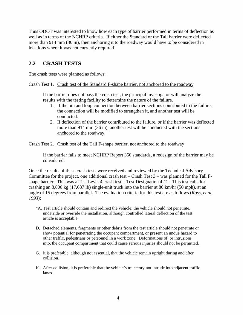
Once the results of these crash tests were received and reviewed by the Technical AdvisoryCommittee for the project, one additional crash test – Crash Test 3 – was planned for the Tall F-shape barrier. This was a Test Level 4 crash test – Test Designation 4-12. This test calls forcrashing an 8,000 kg (17,637 lb) single-unit truck into the barrier at 80 km/hr (50 mph), at anangle of 15 degrees from parallel. The evaluation criteria for this test are as follows (Ross, et al.1993):
“A. Test article should contain and redirect the vehicle; the vehicle should not penetrate,underride or override the installation, although controlled lateral deflection of the testarticle is acceptable.
D. Detached elements, fragments or other debris from the test article should not penetrate orshow potential for penetrating the occupant compartment, or present an undue hazard toother traffic, pedestrians or personnel in a work zone. Deformations of, or intrusionsinto, the occupant compartment that could cause serious injuries should not be permitted.
G. It is preferable, although not essential, that the vehicle remain upright during and aftercollision.
K. After collision, it is preferable that the vehicle’s trajectory not intrude into adjacent trafficlanes.

5
M. The exit angle from the test article preferably should be less than 60 percent of the testimpact angle, measured at time of vehicle loss of contact with test device.”
2.3 SELECTION OF CRASH TESTING FACILITIES
Seven crash testing facilities were invited to bid on the project. Three firms submitted bids, andKARCO Engineering in Adelanto, California was selected to conduct the crash testing.


7
3.0 RESULTS AND DISCUSSION
3.1 CRASH TEST 1 - STANDARD F-SHAPE BARRIER
On April 17, 2001 Crash Test 1 was conducted. The test article was the Standard F-shapeprecast concrete barrier with pin and loop connections. Sixteen barrier segments, totaling 61 m(200 ft) were placed in a line and connected together. The line of barriers was placed at an angleof 25 degrees from parallel. The string of barriers was placed directly onto the surface of asphaltconcrete with no extra anchoring used. This setup represents the typical method ODOT employswith barrier installation.
The Principal Investigator inspected the layout of the barrier and determined that it was set upcorrectly. There was a sizable earthen terrace, about 2 m (6 ft) tall, that encircled the test facility.This terrace happened to pass within 4 m (12 ft) of the downstream end of the barrier, therebycausing a potential bottleneck for the test vehicle to impact after it passed the end of the barrierrun. It was decided that the terrace was situated well enough beyond the test area that anyimpact with the terrace would not be likely to affect the outcome of the test. Permission wasgranted to proceed with the test.
The test vehicle provided by KARCO Engineering was a 1995 Chevrolet Cheyenne ¾ ton pickup(Figure 3.1) with a gross static weight of 2,041 kg (4,500 lb). This weight was within theallowable range of �45 kg, as specified in NCHRP Report 350 (Ross, et al. 1993). The pickupwas connected by nylon line to a tow cable, which was embedded in a track. The pickup wastowed toward the barrier by a tow vehicle. At the point of impact the test vehicle had achieved aspeed of 100.74 km/h (62.6 mph).
Figure 3.1: Test vehicle prior to Crash Test 1, showing angle of impact

8
The point of impact occurred on barrier segment #8, approximately 800 mm (2.6 ft) downstreamfrom the joint between segments #7 and #8. As shown in Figure 3.2, the barrier segments weredeflected from the impact; the maximum deflection was 760 mm (30 inches), with no perceptiblerebound. The Principal Investigator noted after the impact that there were some minor hairlinecracks visible on the backside of the barrier segment #8, which received the initial impact. Noneof the connection pins failed or were bent. No barrier segment tipped. The test results, asprovided by KARCO Engineering, are included in Appendix C and summarized in Table 3.1. Asshown in the table, the Standard F-shape barrier passed all of the NCHRP requirements. Theterrace was judged not to have had a material effect on the outcome of the test. Thus the crashtest of the Standard F-shape barrier was judged to be successful.
Figure 3.2: Standard F-shape barrier following Crash Test 1
Table 3.1: Crash Test 1 results - Standard F-shape barrier and 2,000 kg truck
Parameter Result NCHRP RequirementVehicle containment &redirection Pass
Vehicle redirection in a controlled manner; nounderride or override allowed.
Debris from the impact PassNo debris from the impact should present a hazardto occupant compartment or others.
Occupant compartment PassNo hazardous deformation or intrusion of theoccupant compartment
Vehicle attitude PassVehicle should remain upright; moderate roll, pitchand yaw acceptable
Occupant impact velocitylongitudinal direction
X: -5.85 m/secY: 0.0 m/sec Allowable, not to exceed 12 m/sec
Occupant ridedown accelerationlongitudinal direction
X: -12.52 GY: -18.23 G Allowable, not to exceed 20 G
Vehicle exit trajectory 11 degrees Preferred not to exceed 60% x 25 = 15 degreesMaximum barrier deflection 760 mm (30 inches) No NCHRP requirement; ODOT requirement: 914
mm (36 in)

9
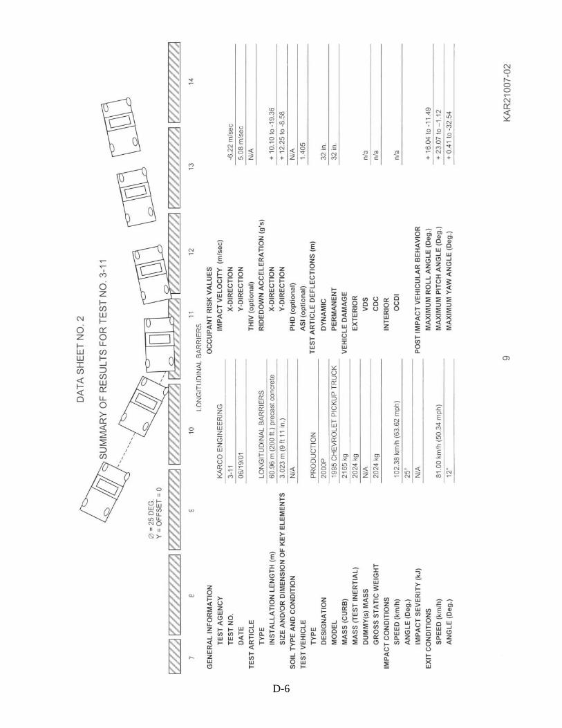
3.2 CRASH TEST 2 - TALL F-SHAPE BARRIER
On June 19, 2001 Crash Test 2 was conducted. The test article was the Tall F-shape precastconcrete barrier with bolted “C-shape” connection. Twenty barrier segments, totaling 61 m (200ft) were placed in a line and connected together. Again, the line of barriers was placed at anangle of 25 degrees from parallel. The string of barriers was placed directly onto the surface ofasphalt concrete with no extra anchoring used. As indicated above, this setup represents thetypical method ODOT employs with barrier installation.
The Principal Investigator inspected the layout of the barrier and determined that it was set upcorrectly. Permission was granted to proceed with the test.
The test vehicle was a 1995 Chevrolet Cheyenne ¾ ton pickup (Figure 3.3) with a gross staticweight of 2,024 kg (4,462 lb). This weight was within the allowable range of �45 kg, asspecified in NCHRP Report 350 (Ross, et al. 1993). The pickup was connected by nylon line toa tow cable, which was embedded in a track. The pickup was towed toward the barrier by a towvehicle. At the point of impact the test vehicle had achieved a speed of 102.38 km/h (63.6 mph).This velocity was within the allowable range of �4 km/h, as specified in NCHRP Report 350(Ross, et al. 1993).
Figure 3.3: Test vehicle prior to Crash Test 2, showing angle of impact
The point of impact occurred on barrier segment #10, approximately 150 mm (6 in) upstream ofthe joint between segments #10 and #11. As shown in Figure 3.4, the barrier segments weredeflected from the impact; the maximum deflection was 813 mm (32 inches), with no perceptiblerebound.

10
Figure 3.4: Tall F-shape barrier following Crash Test 2
The test results, as provided by KARCO Engineering, are included in Appendix D andsummarized in Table 3.2. As shown in the table, the Tall F-shape barrier passed all of theNCHRP requirements. Again, the terrace was judged not to have had a material effect on theoutcome of the test. Thus the crash test of the Tall F-shape barrier was judged to be successful.
The Principal Investigator noted some minor spalling of concrete at the joint where impactoccurred. None of the connecting bolts failed or was bent. The Principal Investigator requestedthat KARCO make special note in the report of the disassembly of the system, with regard topotential difficulties of bent bolts and their removal. KARCO personnel reported that they hadno major problems taking the system apart, only the need to realign some of the segments so thatthe bolts could be turned easier.
Table 3.2: Crash Test 2 results - Tall F-shape barrier and 2,000 kg truck
Parameter Result NCHRP RequirementVehicle containment &redirection Pass
Vehicle redirection in a controlled manner; nounderride or override allowed.
Debris from the impact PassNo debris from the impact should present a hazardto occupant compartment or others.
Occupant compartment PassNo hazardous deformation or intrusion of theoccupant compartment
Vehicle attitude PassVehicle should remain upright; moderate roll, pitchand yaw acceptable
Occupant impact velocitylongitudinal direction
X: -6.22 m/secY: 5.08 m/sec Allowable, not to exceed 12 m/sec
Occupant ridedown accelerationlongitudinal direction
X: -19.36 GY: 12.25 G Allowable, not to exceed 20 G
Vehicle exit trajectory 12 degrees Preferred not to exceed 60% x 25 = 15 degreesMaximum barrier deflection 813 mm (32 inches) No NCHRP requirement; ODOT requirement: 914
mm (36 in)

11
3.3 CRASH TEST 3 - SECOND TEST OF THE TALL F-SHAPEBARRIER
The ODOT Research work plan and contract had provided for the possibility of a crash testfailure, necessitating at least one subsequent test. Since the first two tests were successful, it wasdecided by the Technical Advisory Committee to subject the Tall F-shape barrier to a testinvolving a larger vehicle, since its intended use was on highways which carried large volumesof trucks. NCHRP Report 350 defines parameters for such a test, Test Level 4 (Test Designation4-12), which utilizes a single-unit truck weighing 8,000 kg (17,637 lb). This test calls forcrashing the truck into the barrier at a speed of 80 km/h (50 mph) and at an impact angle of 15degrees. The Test Level 4 impact is calculated to be slightly lower in expended energy than theTest Level 3, but with the higher center of gravity of the test vehicle, a critical concern is agreater tendency for the truck to tip over the barrier.
Crash Test 3 was conducted on September 18, 2001. The test article was the Tall F-shapeprecast concrete barrier, as used in Test 2. The barrier sections were assembled to ensure that thesegments in the impact area were in like-new condition and had not been affected by the earliertest.
The test vehicle provided by KARCO Engineering was a 1995 Ford F 600 box truck (Figure 3.5)with a curb weight of 4,312 kg (9,506 lb), with added ballast bringing it to a gross static weightof 7,917 kg (17,454 lb). This weight was within the allowable range of �200 kg, as specified inNCHRP Report 350 (Ross, et al. 1993). The truck was connected by nylon line to a tow cable,which was embedded in a track. The truck was towed toward the barrier, and at the point ofimpact it had achieved a speed of 76.06 km/h (47.3 mph). This velocity was within the allowablerange of �5 km/h, as specified in NCHRP Report 350 (Ross, et al. 1993).
Figure 3.5: Test vehicle prior to Crash Test 3, showing angle of impact
12
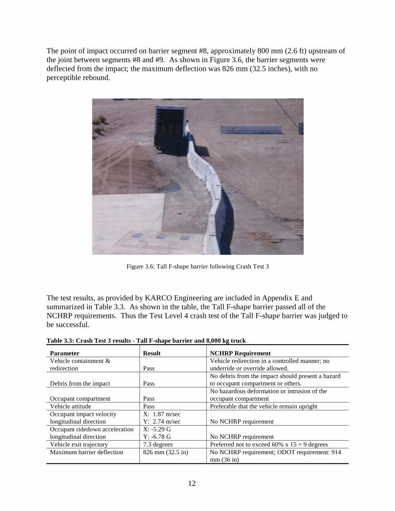
The point of impact occurred on barrier segment #8, approximately 800 mm (2.6 ft) upstream ofthe joint between segments #8 and #9. As shown in Figure 3.6, the barrier segments weredeflected from the impact; the maximum deflection was 826 mm (32.5 inches), with noperceptible rebound.
Figure 3.6: Tall F-shape barrier following Crash Test 3
The test results, as provided by KARCO Engineering are included in Appendix E andsummarized in Table 3.3. As shown in the table, the Tall F-shape barrier passed all of theNCHRP requirements. Thus the Test Level 4 crash test of the Tall F-shape barrier was judged tobe successful.
Table 3.3: Crash Test 3 results - Tall F-shape barrier and 8,000 kg truck
Parameter Result NCHRP RequirementVehicle containment &redirection Pass
Vehicle redirection in a controlled manner; nounderride or override allowed.
Debris from the impact PassNo debris from the impact should present a hazardto occupant compartment or others.
Occupant compartment PassNo hazardous deformation or intrusion of theoccupant compartment
Vehicle attitude Pass Preferable that the vehicle remain uprightOccupant impact velocitylongitudinal direction
X: 1.87 m/secY: 2.74 m/sec No NCHRP requirement
Occupant ridedown accelerationlongitudinal direction
X: -5.29 GY: -6.78 G No NCHRP requirement
Vehicle exit trajectory 7.3 degrees Preferred not to exceed 60% x 15 = 9 degreesMaximum barrier deflection 826 mm (32.5 in) No NCHRP requirement; ODOT requirement: 914
mm (36 in)
13
Unforeseen circumstances prevented the Principal Investigator from attending this test. The testfacility personnel were asked to inspect the barrier for damage following the test; there was nomention of undue damage to the barrier. The barrier was disassembled with no broken or bentbolts encountered.
KARCO Engineering disclosed after the test that they had remotely applied the brakes to thetruck after the impact, while the truck’s wheels were not in contact with the ground. Theyexplained that they were concerned that the momentum of the test vehicle would carry it into thevideo recording equipment set up for the test. Applying the brakes to a test vehicle is not normalprocedure. In addition to the application of the brakes, the video recording showed that bothfront wheels turned sharply to the right when the truck came back in contact with the ground,thus causing a plowing effect in the dirt. Thus both the plowing of the front wheels and theremote braking had an effect on the stopping behavior of the vehicle. While the vehicle probablydid come to a halt sooner due to the remote braking, this was not judged to have significantlyaffected the test outcome.

15
4.0 DISCUSSION AND CONCLUSIONS
4.1 NCHRP REQUIREMENTS
The principal objective of this research was to determine whether Oregon’s Standard F-shapeand Tall F-shape precast concrete barriers could meet the requirements of NCHRP Report 350.FHWA has specified that these safety devices meet the NCHRP Test Level 3 requirements.
Printed reports and videotapes of the first two crash tests were sent to FHWA for review andapproval. FHWA initially noted that KARCO Engineering’s report on the first crash test did notcontain some documentation as required by NCHRP Report 350. KARCO Engineeringsubsequently submitted an amended report to the satisfaction of FHWA.
In its letter of acceptance, FHWA both acknowledged that the barriers had met the NCHRPrequirements and also praised their performance:
“Based on the reported results of the tests run on these barriers, both the 810-mmtall and the 1065-mm tall designs are considered to meet the evaluation criteria ofthe National Cooperative Highway Research Program (NCHRP) Report 350 attest level 3 (TL-3) and may be used on the National Highway System when suchuse is acceptable to the contracting authority. Both barriers exhibited the leastamount of deflection and resulted in the most stable, post-impact vehicletrajectories of any free-standing, precast barrier tested to date.” (Wright 2001)
This recognition from FHWA has generated calls from ten states, expressing an interest inODOT’s barrier design.
4.2 DESIGN CONSIDERATIONS
Given that the Tall F-shape barrier deflected slightly more than the Standard F-shape barrier inTest Level 3, the ODOT design team identified two issues it wished to address:
� Although the Tall Barrier is more massive, why didn’t it perform better than the StandardBarrier?
� What could ODOT do to improve the Tall Barrier to make it outperform the StandardBarrier?
Upon further analysis of the test results and video recordings, ODOT speculated that the TallBarrier deflected more than the Standard Barrier probably because a) the impact on the TallBarrier was so close to the joint; and b) the length of the Tall Barrier segments is 810 mm (30 in)shorter than that of the Standard Barrier segments, making the system more flexible.

16
If the barrier segments were lengthened to the same dimension as the standard barrier – i.e.3.81 m (12.5 ft), it would decrease the flexibility of the system. In addition, each segment wouldthen weigh approximately 3,630 kg (8,000 lb), increasing the resistance to movement on the roadsurface. This design change could be undertaken without further testing, since FHWA considerslengthening of the barrier to be an improvement.
Another beneficial change to the design would be the addition of pinning holes, to be used ifthere were not adequate room for deflection. These design changes have been made, and ODOThas concluded that the Tall F-shape barrier would likely outperform the Standard F-shape barrierin identical tests.
The Test Level 4 results for the Tall Barrier provides useful information on the performance ofthis type of system. A permanent installation of this type of barrier has been shown to containand redirect tractor-trailer trucks (McDevitt 2000). The ODOT crash test, however, employedtemporary precast barrier sections, with no anchoring to the roadway. The barrier as tested wasdeflected less than a meter from the impact of the 8,000 kg truck, and the truck remained uprightand safely redirected. FHWA has reviewed the test results and the video documentation and hasissued a letter acknowledging the effectiveness of the Tall F-shape barrier under Test Level 4conditions:
“Based on the reported results of the test, the 1065-mm tall design satisfies theevaluation criteria of the National Cooperative Highway Research Program(NCHRP) Report 350 for a test level 4 (TL-4) longitudinal barrier and may beused on the National Highway System when such use is acceptable to thecontracting authority.” (Halladay 2001)
4.3 CONCLUSION
Both the currently used Standard F-shape precast concrete barrier and the newly adopted Tall F-shape precast concrete barrier fully satisfy the requirements of NCHRP Report 350. Indeed,FHWA has acknowledged both barriers as having the best performance of any free-standingprecast concrete barrier to date. Furthermore, the performance of the Tall F-shape barrier withlarger trucks, enhanced by the design changes described above, promises to make it veryvaluable as a new safety feature on Oregon’s highways.

17
5.0 REFERENCES
Halladay, Michael. Personal correspondence. Federal Highway Administration. HSA-10/B-86a.November 21, 2001.
McDevitt, Charles F. “Basics of Concrete Barriers,” Public Roads. Turner-Fairbank HighwayResearch Center, Federal Highway Administration, McLean, VA. Vol. 63, No. 5. 2000.
Ross, H.E. Jr., D.L. Sicking, R.A. Zimmer and J.D. Michie. National Cooperative HighwayResearch Program Report 350: Recommended Procedure for the Safety Performance Evaluationof Highway Features. Transportation Research Board. National Academy Press, Washington,DC. 1993.
Wright, Frederick G. Personal correspondence. Federal Highway Administration. HSA-10/B-86.August 17, 2001.


APPENDICES

APPENDIX A:
DESIGN SPECIFICATIONSFOR THE
STANDARD F-SHAPE PRECAST CONCRETE BARRIER

A-1


APPENDIX B
DESIGN SPECIFICATIONSFOR THE
TALL F-SHAPE PRECAST CONCRETE BARRIER


B-1


APPENDIX C
KARCO ENGINEERINGTEST LEVEL 3 CRASH TEST REPORT FOR
STANDARD F-SHAPE CONCRETE BARRIER(EXCERPT)


C-1

C-2

C-3

C-4

APPENDIX D
KARCO ENGINEERINGTEST LEVEL 3 CRASH TEST REPORT FOR
TALL F-SHAPE CONCRETE BARRIER(EXCERPT)

D-1

D-2

D-3

D-4

D-5
D-6
APPENDIX E
KARCO ENGINEERINGTEST LEVEL 4 CRASH TEST REPORT FOR
TALL F-SHAPE CONCRETE BARRIER(EXCERPT)


E-1

E-2

E-3
E-4

E-5

E-6