Embed Size (px)
Citation preview
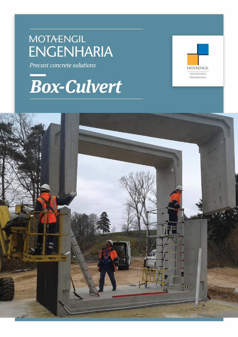
Box-CulvertPrecast concrete solutions
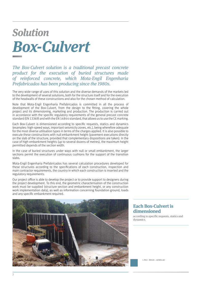
Box-CulvertThe Box-Culvert solution is a traditional precast concrete product for the execution of buried structures made of reinforced concrete, which Mota-Engil Engenharia Prefabricados has been producing since the 1980s.
The very wide range of uses of this solution and the diverse demands of the markets led to the development of several solutions, both for the structure itself and for the execution of the headwalls of these constructions and also for the chosen method of calculation.
Note that Mota-Engil Engenharia Prefabricados is committed in all the process of development of the Box-Culvert, from the design to the fitting, covering the whole project and its dimensioning, marketing and production. The production is carried out in accordance with the specific regulatory requirements of the general precast concrete standard (EN 13369) and with the EN 14844 standard, that allows us to use the CE marking.
Each Box-Culvert is dimensioned according to specific requests, statics and dynamics (examples: high-speed ways, important seismicity zones, etc.), being wherefore adequate for the most diverse utilisation types in terms of the charges applied. It is also possible to execute these constructions with null embankment height (pavement executions directly on the slab of the structure, provided that complementary dispositions are taken). In the case of high embankment heights (up to several dozens of metres), the maximum height permitted depends of the section width.
In the case of buried structures under ways with null or small embankment, the larger sections permit the execution of continuous cushions for the support of the transition slabs.
Mota-Engil Engenharia Prefabricados has several calculation procedures developed for these structures according to the specifications of each construction, inspection and main contractor requirements, the country in which each construction is inserted and the regulatory requirements.
Our project office is able to develop the project or to provide support to designers during the project development. To this end, the geometric characterisation of the construction work must be supplied (structure section and embankment height, or any construction work implementation data), as well as information concerning foundation ground, loads and any specific embankment required.
2
Solution
1
1. PA3 – RD120 – AURILLAC
Each Box-Culvert is dimensionedaccording to specific requests, statics and dynamics.

MOTA-ENGIL ENGENHARIA PREFABRICADOS
3
Application
Regarding the application purpose, these structures are used to compose buried constructions such as hydraulic passageways, technical galleries, underpasses for pedestrians and roads, water retention basins, for agricultural and ecological uses, etc.
The section of these structures is traditionally composed by two overlapping “U”- type pieces or, for the smaller sections, just by a single monolithic piece. For very small sections or in the case of water retention basins, the section is usually composed by one “U”- type piece and a cover slab. It is also possible, if there isn’t a cover slab, to have a section in open culvert.
Section types Monolithic section
Two overlapping “U”- type pieces
One “U”- type piece (with or without cover slab)
1. MONOLITHIC SECTION – SECTION EM37
2. TWO OVERLAPPING “U”- TYPE PIECES
3. ONE “U”- TYPE PIECE AND A COVER SLAB
4. OPEN CULVERT
1
2 4
3
Box-Culvert Solution
4
Section types
Monolithic section
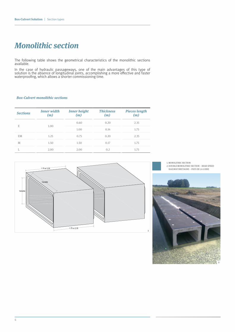
The following table shows the geometrical characteristics of the monolithic sections available.
In the case of hydraulic passageways, one of the main advantages of this type of solution is the absence of longitudinal joints, accomplishing a more effective and faster waterproofing, which allows a shorter commissioning time.
Sections Inner width (m)
Inner height (m)
Thickness (m)
Pieces length (m)
E 1.000.60 0.20 2.35
1.00 0.14 1.75
EM 1.25 0.75 0.20 2.35
M 1.50 1.50 0.17 1.75
L 2.00 2.00 0.2 1.75
Box-Culvert monolithic sections
1. MONOLITHIC SECTION
2. DOUBLE MONOLITHIC SECTION – HIGH-SPEED
RAILWAY BRETAGNE – PAYS DE LA LOIRE
1
2

MOTA-ENGIL ENGENHARIA PREFABRICADOS
5
Two overlapping “U”- type sections
The following table shows the available sections, in which each letter stands for the fixed inner width series.
Note that, additionally to the current sections, a specific study can be performed to consider other types of sections.
Multiple-section galleries (double, triple, etc.) are also possible. To achieve this, the structures are fitted in parallel with a small gap between them, which is filled with concrete later on.
Sections Inner width (m)
Inner height(m)
Slab height(cm)
Wall thickness(cm)
Pieces maximum length (m)
E 1.00 1.00 to 2.00 max.: 25 / min.: 10 max.: 20 / min.: 16 2.50
M 1.50 1.00 to 2.50 max.: 25 / min.: 10 max.: 20 / min.: 16 2.50
L 2.00 1.50 to 2.50 max.: 50 / min.: 20 max.: 30 / min.: 16 2.50
SL 2.50 1.50 to 2.50 max.: 50 / min.: 20 max.: 35 / min.: 20 2.50
XL 3.00 1.50 to 4.00 max.: 45 / min.: 25 max.: 27 / min.: 20 2.50
XXL 3.50 1.50 to 4.00 max.: 45 / min.: 25 max.: 27 / min.: 20 2.50
IV 4.00 2.00 to 4.00 max.: 45 / min.: 25 max.: 27 / min.: 20 2.35
IVM 4.50 3.00 to 5.00 max.: 45 / min.: 30 max.: 35 / min.: 35 2.00
V 5.00 3.00 to 5.00 max.: 45 / min.: 30 max.: 35 / min.: 35 2.00
VM 5.50 1.50 to 6.50 max.: 55 / min.: 30 max.: 45 / min.: 30 2.50
VI 6.00 1.50 to 6.50 max.: 55 / min.: 30 max.: 45 / min.: 30 2.50
VIM 6.50 1.50 to 6.50 max.: 55 / min.: 30 max.: 45 / min.: 30 2.50
VII 7.00 1.50 to 6.50 max.: 55 / min.: 30 max.: 45 / min.: 30 2.50
VIIM 7.50 1.50 to 6.50 max.: 55 / min.: 30 max.: 45 / min.: 30 2.50
VIII 8.00 1.50 to 6.50 max.: 55 / min.: 30 max.: 45 / min.: 30 2.50
VIIIM 8.50 1.50 to 6.50 max.: 55 / min.: 30 max.: 45 / min.: 30 2.50
IX 9.00 1.50 to 6.50 max.: 55 / min.: 30 max.: 45 / min.: 30 2.50
IXM 9.50 1.50 to 5.00 max.: 55 / min.: 30 max.: 45 / min.: 30 2.50
Note 1: For pieces with spigot/socket system, the length is usually 2.35 m, with the exception of IVM and V sections that maintains the length of 2.00 m.Note 2: Other sections and slab/wall dimensions may be studied according to the clients request.
L-int
H-i
nt
H-i
nt
L-Comp.
1. OVERLAPPING “U”- TYPE BOX-CULVERT DIAGRAMS
Lenght
Inner width
Inne
r hei
ght
Inne
r hei
ght

Box-Culvert Solution
6
Section types
4)
Fitting of another set of pieces.
Metal part
Rubber
Sealing with mortar
5)
Fitting of metal connections and sealing with mortar.
Lower "U" - type piece
1)
Fitting of the lower piece (Box-Culvert).
Rubber
Rubber
Connection steel
Uper piece(Cover slab)
2)
Fitting of the upper piece (Cover slab).
Sealing with mortar
Rubber
3)
Connection between pieces with steel and sealing mortar. Application of rubber around the spigot.
Open Culvert section with or without cover slab
The “U”- type piece solution allows the execution of open culverts. When an open culvert has a cover slab, it makes it possible to construct very small sections or buried water retention basins. In the latter case and given the need of ensuring total waterproofness, specific characteristics are used for sealing the transversal joints based on mechanical compression.
1. “U”- TYPE PIECE WITH COVER
SLAB BOX-CULVERT DIAGRAMS1
MOTA-ENGIL ENGENHARIA PREFABRICADOS
7
3 4 5
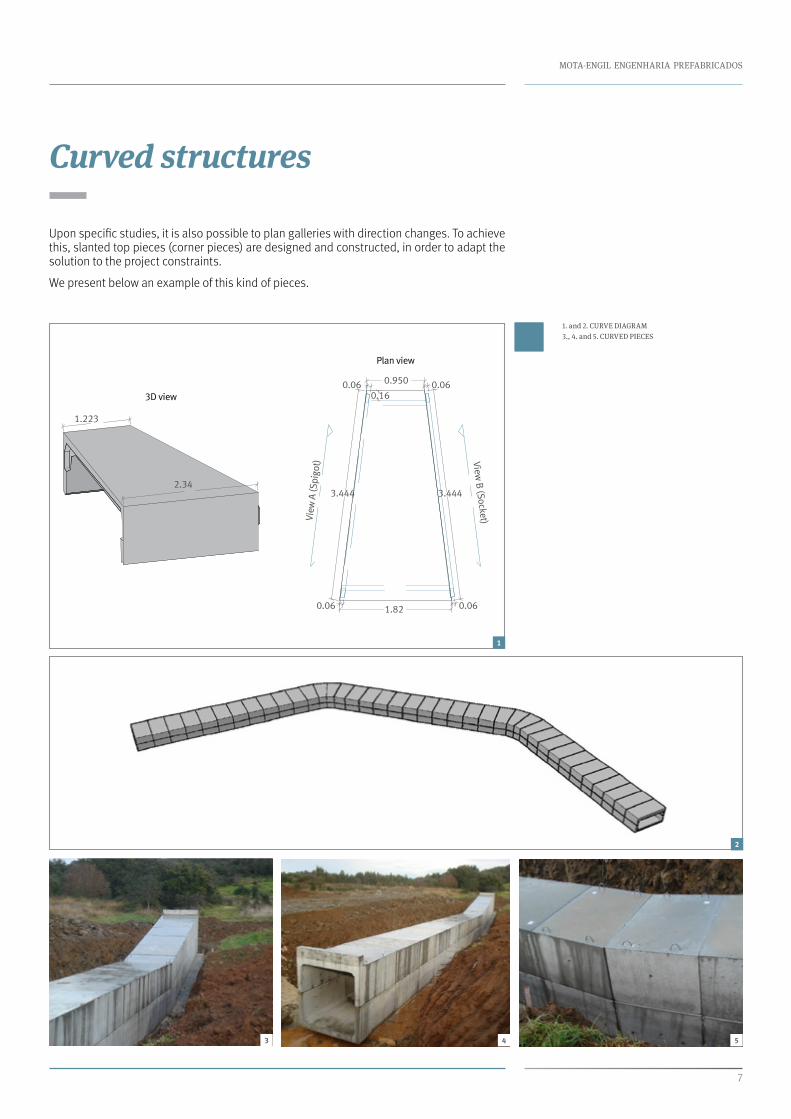
1. and 2. CURVE DIAGRAM
3., 4. and 5. CURVED PIECES
Plan view
0.06
1.82
3.4443.444
0.950 0.06
0.06 0.06
View B (Socket)Vi
ew A
(Spi
got)
0.163D view
1.223
2.34
Curved structures
Upon specific studies, it is also possible to plan galleries with direction changes. To achieve this, slanted top pieces (corner pieces) are designed and constructed, in order to adapt the solution to the project constraints.
We present below an example of this kind of pieces.
2
1

Box-Culvert Solution
8
Headwalls and Wingwalls
Headwalls and Wingwalls
The Box-Culvert headwalls may be executed with wingwalls, regardless of the section type or dimensions. It is possible to build them in different ways: using precast concrete panels and concreting of an on-site sill (this solution is mostly used for hydraulic passageways); through the execution of “T”- type walls designed for this purpose; or using walls with buttresses.
In order to reduce the visual impact of the headwalls and wingwalls on the surrounding environment, they may be constructed with various types of textures and relief.
1
2
The structures surfacemay have cast-in textures reducing the visual impact on the surrounding environment.
1. PA2 – RD 120 – AURILLAC
2. WALL DETAIL PA2 – RD 120

MOTA-ENGIL ENGENHARIA PREFABRICADOS
9
Type 1 Applied for sections up to 3.00 m
1
Type 3 Applied for sections between 5.50 and 6.50 m
2
2
Type 2 Applied for sections between 3.00 and 5.50 m

Box-Culvert Solution
10
Production
1
2
3
Production
The materials currently used for manufacturing these pieces are concrete, with at least compressive strength class C30/37 and steel class B500C. Upon particular and more restrictive specifications, materials can be changed (e.g., for the French market, the concrete strength class is usually C40/50 with environmental exposure class XC4/XF1).
The concrete is manufactured at Mota-Engil plants, in Nelas and Rio Maior, using Portland cement siloed in bulk with class 42.5 or 52.5, limestone or granitic aggregate, alkali-silica non reactive, with good mechanical and fracture characteristics, with admixtures to reduce water in the batch and to obtain higher initial strengths, without damaging the final strengths or the batch quality.
The concreting is continuously performed for each piece and the moulds have adequate high-frequency vibration integrated.
The concrete used has been conceived to allow the demoulding 16 to 18 hours after the beginning of the curing process, obtaining at least a resistance of 15 Mpa.
The pieces are handled using certified and carefully placed nail-type anchor bolts. For “U”-type pieces, the lower placement elements are turned and already stocked in the correct on-site position.
Before dispatch, the outer faces of the pieces touching the soil are painted using a bitumen emulsion for increased protection.
The described production process complies with the quality system implemented at Mota-Engil Engenharia Prefabricados, which covers from material properties to the observance of dimensional tolerances, according to the CE marking standard, EN 14844, and the general standard for precast concrete products – EN 13369.
Set parametersBar diameter D = 8 mm
StatisticNumber of measured bars N = 11Average measured cover m = 38.0 mmStandard deviation sa = 1.4 mmMaximum of measured covers Max = 41 mmMinimum of measured covers Min = 36 mmSpan R = 5 mm
Measured covers [mm]38 36 37 39 38 39 38 38 4138 36
The concrete is manufactured at Mota-Engil plants, in Nelas and Rio Maior.
Cover [mm
]0
1020
3040
4
1. STEEL REINFORCEMENT ASSEMBLY
2. PLACEMENT OF SPACERS
3. PIECE DEMOULDING
4. COVER MEASUREMENT
MOTA-ENGIL ENGENHARIA PREFABRICADOS
11
On-site works
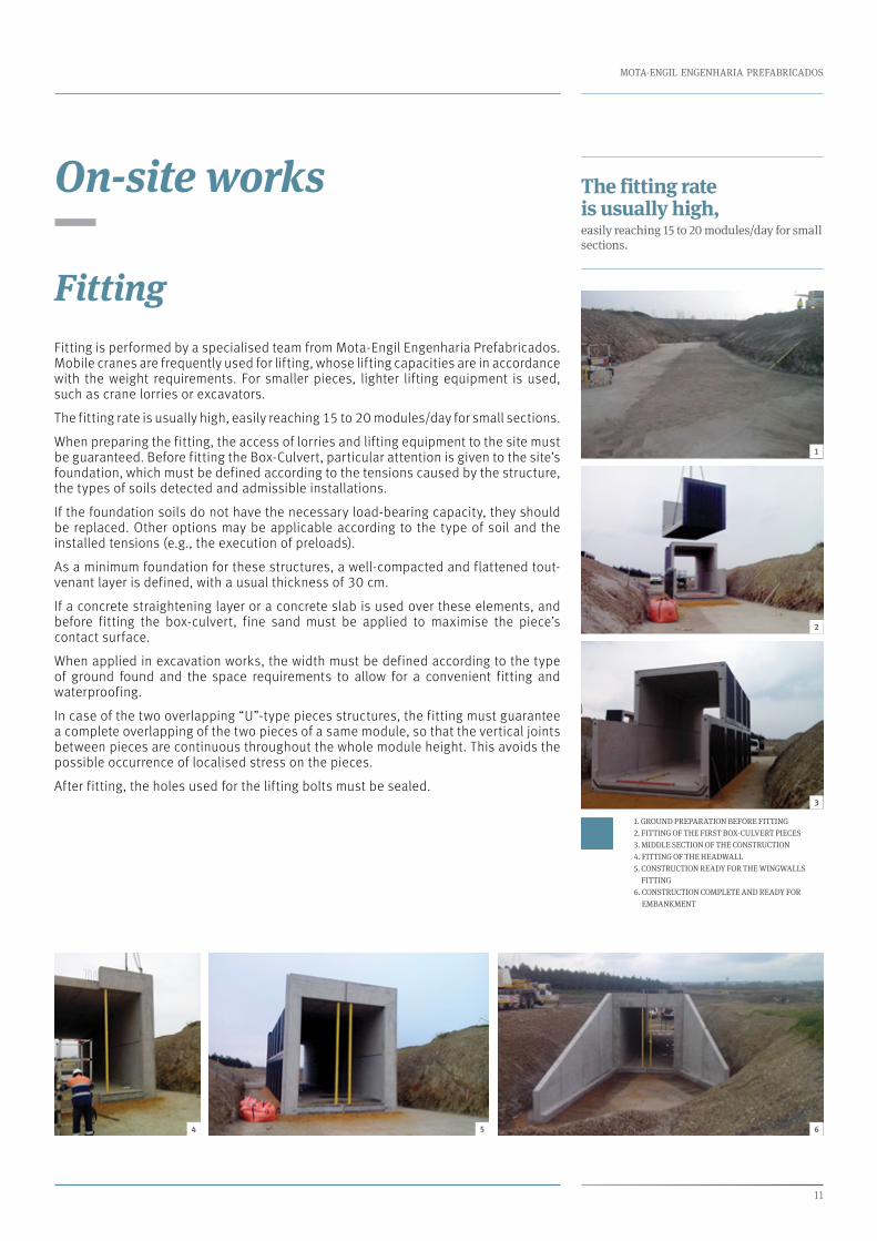
FittingFitting is performed by a specialised team from Mota-Engil Engenharia Prefabricados. Mobile cranes are frequently used for lifting, whose lifting capacities are in accordance with the weight requirements. For smaller pieces, lighter lifting equipment is used, such as crane lorries or excavators.
The fitting rate is usually high, easily reaching 15 to 20 modules/day for small sections.
When preparing the fitting, the access of lorries and lifting equipment to the site must be guaranteed. Before fitting the Box-Culvert, particular attention is given to the site’s foundation, which must be defined according to the tensions caused by the structure, the types of soils detected and admissible installations.
If the foundation soils do not have the necessary load-bearing capacity, they should be replaced. Other options may be applicable according to the type of soil and the installed tensions (e.g., the execution of preloads).
As a minimum foundation for these structures, a well-compacted and flattened tout-venant layer is defined, with a usual thickness of 30 cm.
If a concrete straightening layer or a concrete slab is used over these elements, and before fitting the box-culvert, fine sand must be applied to maximise the piece’s contact surface.
When applied in excavation works, the width must be defined according to the type of ground found and the space requirements to allow for a convenient fitting and waterproofing.
In case of the two overlapping “U”-type pieces structures, the fitting must guarantee a complete overlapping of the two pieces of a same module, so that the vertical joints between pieces are continuous throughout the whole module height. This avoids the possible occurrence of localised stress on the pieces.
After fitting, the holes used for the lifting bolts must be sealed.
1
2
3
54 6
The fitting rate is usually high,easily reaching 15 to 20 modules/day for small sections.
1. GROUND PREPARATION BEFORE FITTING
2. FITTING OF THE FIRST BOX-CULVERT PIECES
3. MIDDLE SECTION OF THE CONSTRUCTION
4. FITTING OF THE HEADWALL
5. CONSTRUCTION READY FOR THE WINGWALLS
FITTING
6. CONSTRUCTION COMPLETE AND READY FOR
EMBANKMENT
Box-Culvert Solution
12
On-site works
h
0.10 0.10
B
B
C
C
A
A
Asphalt membrane
Rubber
Primerapplication
Primerapplication
Longitudinaljoint
Lower jointsealing
Roundexbar
Roundexbar
WW/2
W = max.: 25 mm min.: 10 mm
Depth max:25 mm
Bitumen emulsion(in factory)
Lowerjoint
Asphalt membrane
Asphalt membrane
Longitudinaland transversejoint
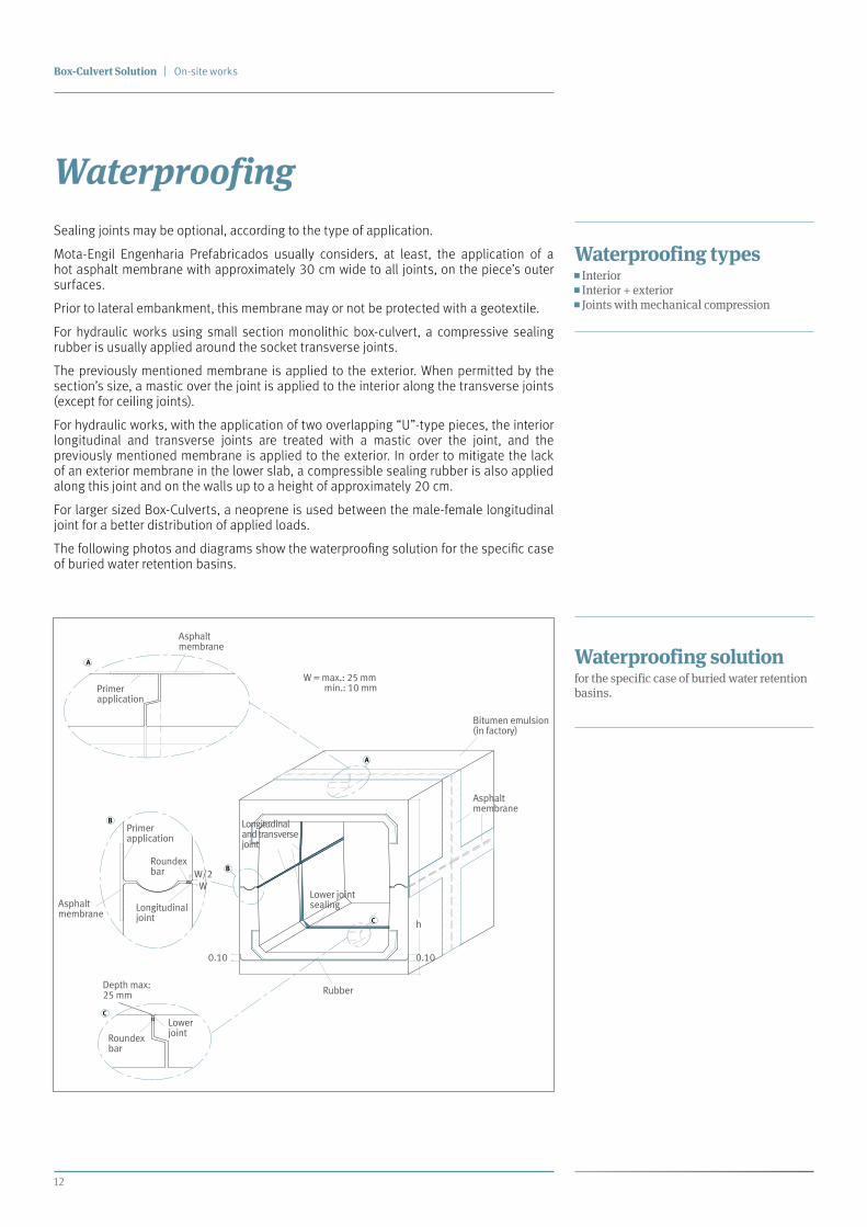
WaterproofingSealing joints may be optional, according to the type of application.
Mota-Engil Engenharia Prefabricados usually considers, at least, the application of a hot asphalt membrane with approximately 30 cm wide to all joints, on the piece’s outer surfaces.
Prior to lateral embankment, this membrane may or not be protected with a geotextile.
For hydraulic works using small section monolithic box-culvert, a compressive sealing rubber is usually applied around the socket transverse joints.
The previously mentioned membrane is applied to the exterior. When permitted by the section’s size, a mastic over the joint is applied to the interior along the transverse joints (except for ceiling joints).
For hydraulic works, with the application of two overlapping “U”-type pieces, the interior longitudinal and transverse joints are treated with a mastic over the joint, and the previously mentioned membrane is applied to the exterior. In order to mitigate the lack of an exterior membrane in the lower slab, a compressible sealing rubber is also applied along this joint and on the walls up to a height of approximately 20 cm.
For larger sized Box-Culverts, a neoprene is used between the male-female longitudinal joint for a better distribution of applied loads.
The following photos and diagrams show the waterproofing solution for the specific case of buried water retention basins.
Waterproofing types Interior Interior + exterior Joints with mechanical compression
Waterproofing solutionfor the specific case of buried water retention basins.

MOTA-ENGIL ENGENHARIA PREFABRICADOS
13
Before executing embankments, and considering larger-sized box-culverts, drains must be applied at the lower slab level in the construction’s exterior. These drains must be covered by a layer of gravel, which is covered by geotextile.
The embankments must be performed symmetrically by layers, and height differences must not surpass 50 cm. A careful compaction of the ground must be performed next to the structure, without damaging the waterproofing membranes and without using heavy duty mechanical equipment. The embankment materials must be appropriate for the task, without larger-sized elements (maximum of 20 mm).
The embankment may be asymmetrical when previously considered during project design, and if no other alternative is available.
1. MASTIC APPLICATION
2. SURFACE CLEANSING AND PERFECTING
3. FINISHED JOINT
2 3
The longitudinal joints of the two overlapping “U”-type pieces are always male-female type, while the transverse joints of all section types may be smooth (dry joint) or with spigot and socket.
1
Box-Culvert Solution
14
Main advantages
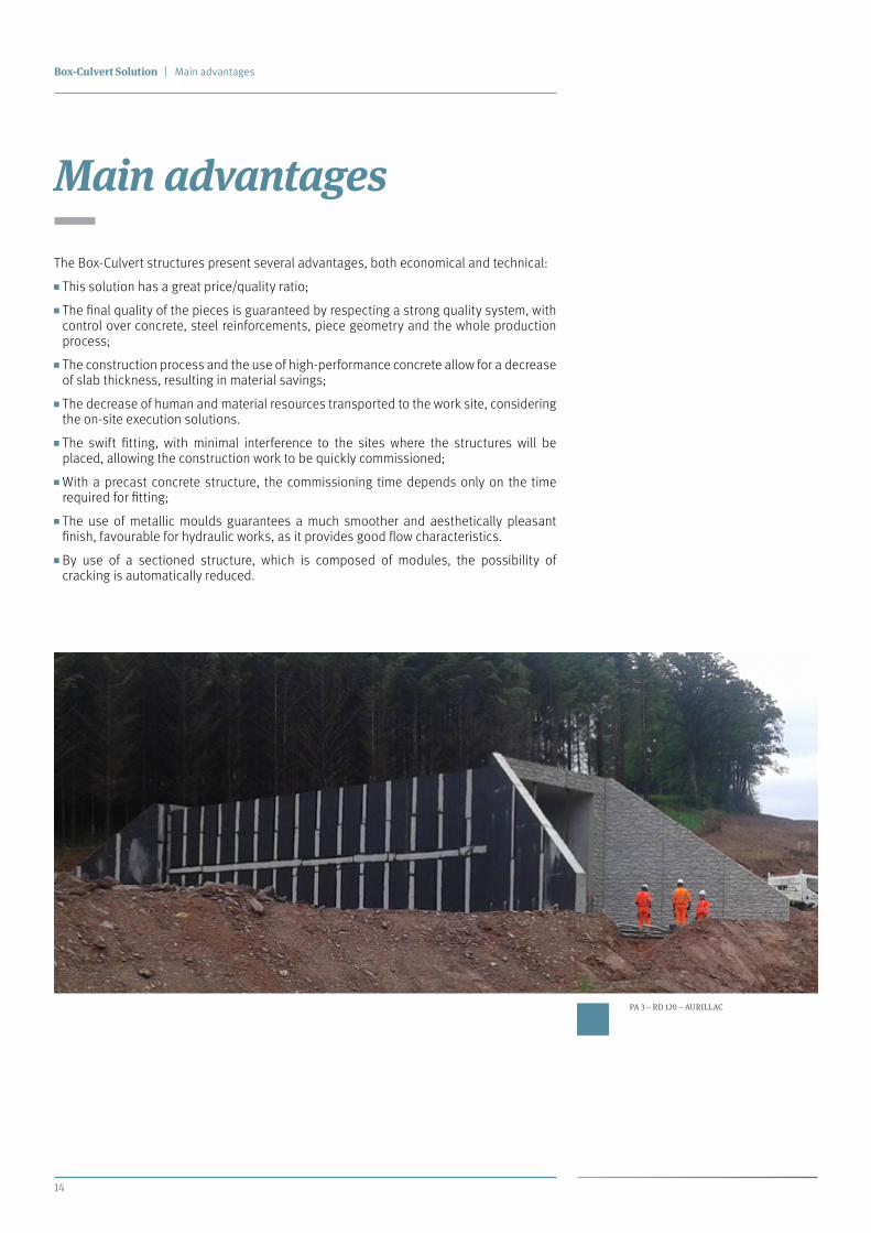
PA 3 – RD 120 – AURILLAC
Main advantages
The Box-Culvert structures present several advantages, both economical and technical:
This solution has a great price/quality ratio;
The final quality of the pieces is guaranteed by respecting a strong quality system, with control over concrete, steel reinforcements, piece geometry and the whole production process;
The construction process and the use of high-performance concrete allow for a decrease of slab thickness, resulting in material savings;
The decrease of human and material resources transported to the work site, considering the on-site execution solutions.
The swift fitting, with minimal interference to the sites where the structures will be placed, allowing the construction work to be quickly commissioned;
With a precast concrete structure, the commissioning time depends only on the time required for fitting;
The use of metallic moulds guarantees a much smoother and aesthetically pleasant finish, favourable for hydraulic works, as it provides good flow characteristics.
By use of a sectioned structure, which is composed of modules, the possibility of cracking is automatically reduced.
MOTA-ENGIL ENGENHARIA PREFABRICADOS
15
1 2
3 4
5
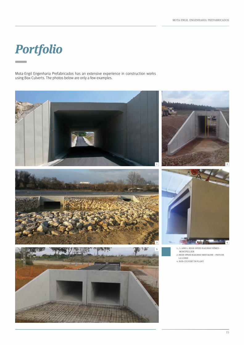
Portfolio
Mota-Engil Engenharia Prefabricados has an extensive experience in construction works using Box-Culverts. The photos below are only a few examples.
1., 3. AND 5. HIGH-SPEED RAILWAY NÎMES –
MONTPELLIER
2. HIGH-SPEED RAILWAY BRETAGNE – PAYS DE
LA LOIRE
4. BOX-CULVERT IN PLANT
Concrete Claddings
Buildings
Box-Culverts
Retaining Walls
Reservoirs
GRC
Noise Barriers
Bridges
Tunnels
Precast concrete solutions
www.mota-engil.com
Offices
Rua do Rego Lameiro, No. 38 4300-454 Porto – Portugaltel.: +351 225 190 300fax: +351 225 191 261
[email protected]@mota-engil.fr
Rio Maior Plant
Zona Industrial de Rio Maior 2040-357 Rio Maior – Portugaltel.: +351 243 994 133
Nelas Plant
Zona Industrial de Nelas 3520-095 Nelas – Portugaltel.: +351 232 945 095
Mota-Engil, Engenharia e Construção, S.A.
Equity Capital: 100,000,000.00€
Registered at the Amarante Registry of Companies under No. 500 197 814
VAT: 500 197 814
Construction Permit No. 10
Registered Office: Casa da Calçada Largo do Paço No. 6 4600-017 Cepelos – Amarante - Portugal
Valid certifications within Portugal
CÓ
D.0
2.V
1.16