Embed Size (px)
Citation preview

Journal of Flow Control, Measurement & Visualization, 2014, 2, 138-153 Published Online October 2014 in SciRes. http://www.scirp.org/journal/jfcmv http://dx.doi.org/10.4236/jfcmv.2014.24016
How to cite this paper: Wang, S.F., Sato, K. and Kagawa, T. (2014) Precise Positioning of Pneumatic Artificial Muscle Sys-tems. Journal of Flow Control, Measurement & Visualization, 2, 138-153. http://dx.doi.org/10.4236/jfcmv.2014.24016
Precise Positioning of Pneumatic Artificial Muscle Systems Shaofei Wang, Kaiji Sato, Toshiharu Kagawa Interdisciplinary Graduate School of Science and Engineering, Tokyo Institute of Technology, Yokohama, Japan Email: [email protected] Received 7 June 2014; revised 12 September 2014; accepted 22 September 2014
Copyright © 2014 by authors and Scientific Research Publishing Inc. This work is licensed under the Creative Commons Attribution International License (CC BY). http://creativecommons.org/licenses/by/4.0/
Abstract Pneumatic artificial muscles (PAMs) currently possess a high power-to-weight ratio, a high power- to-volume ratio, and a high degree of safety. They have therefore been applied to many power as-sist devices and positioning mechanisms such as bionic robots, welfare devices, and parallel ma-nipulators. However, the significant nonlinear characteristics of PAM mechanisms limit their posi-tioning accuracies. The accuracies are generally lower than 5 µm, which preclude the PAM from precision systems. Nevertheless, enhancing the positioning accuracy is desired to extend the ap-plication fields of PAMs. This study aims to clarify a practical controller design method to achieve the precise positioning of PAM systems. As the first step of this research, a linear motion mechan-ism with a pair of McKibben PAMs was constructed and a conventional dynamic model for this system is introduced. The dynamic model is used to explain the basic characteristics of the PAM mechanism and discuss the necessary characteristics for precise positioning. Then open-loop step and sinusoidal responses of the PAM mechanism were examined by experimental and simulated results. Next, for precise positioning, the practical controller design procedure is discussed and determined based on the measured open-loop responses. The proposed controller design proce-dure can be easily implemented into PAM mechanisms without an exact dynamic model. The posi-tioning performance of such a system was experimentally evaluated. The experimental results show that although the positioning accuracy depends on the target position, the positioning error is lower than 1 µm even in the worst case and the positioning resolution can be set to 0.5 µm.
Keywords Precision, Positioning, McKibben Pneumatic Muscle, Pneumatic Artificial Muscle, Accuracy
1. Introduction McKibben pneumatic artificial muscles, which are generally called pneumatic artificial muscles (PAMs), consist

S. F. Wang et al.
139
of an inflatable rubber tube sheathed by a braided mesh. It generates a pulling force via pressurized air and con-tracts in the axial direction while expanding in the radial direction. PAMs possess many advantages over tradi-tional motor actuators, such as a high power-to-weight ratio, a high power-to-volume ratio, a high degree of safety [1], and stick-slip-free operation [2]. They have therefore been applied in bionic robots [3] [4], welfare devices [5]-[7], and parallel manipulators [8] [9]. In particular, PAMs attract a great deal of attention in welfare devices. Owing to its high safety, low weight, and powerful output, it has been applied as a power assist device for reha-bilitation applications such as an upper limb exoskeletal rehabilitation robot [5] and a knee-ankle-foot orthosis [6].
However, PAMs have significant nonlinearity [10], creep phenomenon [11], and hysteresis [12]. These pro-vide the low controllability and make it difficult to move finely. Thus precise motion control of PAMs is an im-portant and unsolved problem. Precise motion control of the PAM provides the potential to extend its applica-tion owing to its many advantages. For example, the precise motion control of PAMs can make precise assembly robots powerful and lightweight and precise assembly robots are expected to become safer for the assemblers who work with the robots. In addition, the precise motion of PAMs enables nursing care robots to provide dis-abled people with delicate support such as injections and repairing clothes. A neurosurgical robot using hydrau-lic and pneumatic cylinders for precise positioning has been reported in [13]. Since PAMs have superior charac-teristics compared to hydraulic and pneumatic cylinders in the application of welfare devices, the precise motion of the PAM may also be used for a neurosurgical robot in the future.
In recent years, a variety of control methods have been developed to achieve excellent control performance in PAM mechanisms. These methods can be divided into three categories: conventional Proportional Integral De-rivative (PID) control, nonlinear model-based control, and intelligent control. Conventional PID controllers are typically easy to design. However, they cannot sufficiently compensate for the nonlinearity of PAMs and lead to poor accuracy. The positioning errors by PID controllers are on the level of 0.1˚ for a rotational PAM mechan-ism [14] [15] and 200 µm for a linear PAM mechanism [16].
The nonlinear model-based control is another major approach for PAM mechanisms. Tondu and Lopez pro-posed a sliding mode controller using a nonlinear length-tension model of PAMs [17]. Even though some mod-ified nonlinear model-based controllers with different models were subsequently presented, the positioning ac-curacy was on order of a micrometer because of inaccurate modeling [18]-[20]. Li and Kawashima proposed a nonlinear dynamic model where the force generated by a PAM is a function of the operating pressure and con-traction length of the PAM [21]. The model also contains a viscous damping coefficient. They applied this non-linear model to their PAM control system and reported that the highest positioning accuracy was 6 µm.
Although the nonlinear model-based control provides a positioning accuracy that is higher than PID control for PAM mechanisms, its design procedures require the modeling of mechanisms and a sufficient knowledge of control theory. This makes it difficult to design for engineers who are unfamiliar with the controller design and makes the controller impracticable for real-world applications.
Intelligent control has also been widely used for PAM mechanisms [22]-[25]. The most accurate positioning re-sult by this approach was reported in [25] where the researchers proposed an intelligent switching control method to adjust the gains of the PID controller using neural networks and achieved a rotational positioning error of 0.05˚. The problems of imprecise positioning and complex controller design still exist in intelligent control for PAM me-chanisms due to the necessity of modeling mechanisms and sufficient knowledge of the intelligent algorithm.
This research aims to provide a practical controller design method for the precise motion for PAM mechan-isms. In this paper, a practical and effective controller for the precise positioning of a PAM mechanism with a pair of PAMs is proposed and its usefulness is demonstrated experimentally. Characteristics of the PAM me-chanism are examined by simulation using a conventional dynamic model and by experiment using an experi-mental setup. Comparison results between the simulated and experimental results are used to discuss the useful-ness of the dynamic model in macroscopic analysis and the problems in controller design for precise positioning. Based on the discussion, we propose a practical controller that can be easily designed for precise positioning of the PAM mechanism, and the positioning performances are evaluated experimentally. In contrast to the nonli-near model-based controllers and the intelligent controllers, the proposed controller achieved the sub-micro- meter order positioning accuracy.
2. Characteristics of the PAM Mechanism 2.1. Experimental Setup Figure 1 shows the experimental setup in this research. An antagonistic structure PAM mechanism is used as a

S. F. Wang et al.
140
Figure 1. Experimental setup.
controlled mechanism. This structure is widely used as the basic actuating element in many applications of PAMs [3] [4] [7]. The two PAMs (FESTO DMSP-10-100N-RM-CM) generate pulling forces to push and pull the mover (1.75 kg) along the moving direction in a working range of −1 mm to 1 mm. Air is injected from the pressure supply (0.5 MPa, absolute) and controlled by a 5-port 3-way proportional servo valve (FESTO MPYE- 5-1/8LF-010-B). The pressures in the two PAMs are measured using two pressure sensors (SMC PSE540A-01, resolution: 0.0012 MPa), which are only used for observing the behavior of the mechanism. A linear encoder (GSI Mercury II 5800, resolution: 100 nm) is used as a single feedback sensor in this research. The data pro- cessing unit is used as a controller hardware. The controller is implemented at a sampling rate of 10 kHz.
2.2. Conventional Dynamic Model Figure 2 shows a schematic diagram of a conventional dynamic model of PAM system. This dynamic model is used to examine basic characteristics of the PAM mechanism and discuss essential characteristics for controller design of precise positioning.
In Figure 2, the input voltage of servo valve u determines the effective opening area of the ports which connect to PAM 1, PAM 2 ( 14eS and 12eS ) and atmosphere ( 45eS and 23eS ). The values of 14eS and 12eS are refer to [26] and the values of 45eS and 23eS are decided by fitting the step responses of simulated results to experimental results. The flow dynamic block shown in Figure 2 is modeled as the process of a flow of an ideal gas through a converging nozzle [2] [7] [27]. This process is expressed as a nonlinear function for calcula-tion of mass flow rate. 14m and 12m are the mass flow rates when air flowing into PAM 1 and PAM 2 respec-tively; 45m and 23m are the mass flow rates when air leaking out from PAMs. In this process, the air flow is divided into two regimes which are choked and unchoked flow through the orifice. Based on the differentiation of state equation of ideal gas and the volume estimation [27]-[29], the change rate of pressure in each PAM 1,2P can be calculated [2] [7] [27] [29].
The force generated by a single PAM can be described as a nonlinear function of the contraction length ε and the air pressure P in the PAM [2] [27] [29]. In this research, the nonlinear force is identified as the ex-pression shown as following [21].
( ) ( ) ( ) ( )21 0 2 1 0, atm atm atmF P a P P a b P P b P P bε ε = − + + − + − + (1)
where the contraction length ε is the difference between the original length of PAM 0l and the length after contraction l , atmP is the atmosphere pressure, 0a , 1a , 0b , 1b , 2b are identified coefficients.
Since the PAMs are constructed in an opposing pair configuration in this research, the motion equation of the PAM mechanism can be described as following [2] [27].
( ) ( )1 1 1 2 2 2, , fricMx Bx F P F P Fε ε+ = − − (2)

S. F. Wang et al.
141
Figure 2. Schematic diagram of the dynamic model.
where M is the mass of the mover, x is the position of the mover ( 1 xε = , 2 xε = − ), B is the damping coefficient and is tuned as 20 N s mm⋅ optimally. ( )1 1 1,F Pε and ( )2 2 2,F Pε are forces generated by two PAMs. fricF is the friction force which is represented by a dynamic friction force and a static friction force. The mover is considered to be at a stop in the simulation using the friction force model when the absolute veloc-ity of the mover is smaller than 10−9 m/s. In this case, the friction force acts as the static friction force shown in Figure 3(a) where appF is the applied force to the mover. In the other cases, the friction force acts as the dy-namic friction force shown in Figure 3(b).
From Figure 2 and Equation (2), the general nonlinear dynamic model of the PAM mechanism from the input voltage u to the mover position x can be considered as a 3rd-order system [2] [27].
2.3. Open-Loop Responses of the PAM Mechanism In this section, simulated open-loop responses using the dynamic model and experimental open-loop responses using the actual PAM mechanism are compared. The model parameters were identified from the results of fun-damental experiments. Accordingly, the validity of the dynamic model is confirmed. In addition, as necessary characteristics in the controller design for precise positioning, the open-loop step responses which is the basic action in positioning control and the open-loop sinusoidal responses which can be summarized as gain characte-ristics in control system are investigated.
2.3.1. Open-Loop Step Responses The open-loop step responses of the PAM mechanism were investigated by experimental and simulated results. Figure 4 shows the experimental and simulated time responses of the pressure difference between PAM 1 and PAM 2 (P1 ‒ P2) and the mover position x to the stepwise increasing and decreasing input voltages u. Although a single PAM can contract about 25 mm, the working range of PAMs is smaller than +/−3 mm, because the two PAMs were assembled in the condition of no initial contraction and the experimental setup was constructed in a push-pull structure [30]. In this research, furthermore the pressure supply (compressor) and the servo valve de-crease the working range to +/−1.5 mm. Moreover, according to the time responses in Figure 4, we can observe that the input voltage u out of the range from 1.2 V to −1.2 V saturates the pressure and the mover position.
From these compared results, it can be observed that the simulated results tally with the experimental ones. Besides, no vibration in transient responses can be found both in the simulated and the experimental results. This indicates that step input signals can give smooth and no vibration step responses of the open-loop PAM me-chanism and use for rough positioning.
Based on the simulated and experimental results shown in Figure 4, the static relationship between the posi-tion x and the input voltage u and the relationship between the pressure difference (P1 − P2) and the input vol-tage u are summarized in Figure 5(a) and Figure 5(b) respectively. Both the simulated and the experimental results represent strong nonlinearities, so they should be compensated and can be used as compensators in the controller design shown in Section 3.

S. F. Wang et al.
142
(a) (b)
Figure 3. Friction force in the dynamic model. a) Dynamic friction; b) Static friction.
(a) (b)
Figure 4. Open-loop step responses of the PAM mechanism.
2.3.2. Sinusoidal Responses Figure 6 shows the experimental and simulated time responses to a sinusoidal input (amplitude = 1 (V), fre-quency = 1 (Hz), offset = 0 (V)). It can be found that the simulated result broadly corresponds with the experi-mental result when the mover moves in a large range.
During precise positioning, the position of mover is adjusted finely and small vibration is reduced around each target position, so the input-output relationship of vibration in various target position should be clarified. Figure 7(a) shows the experimental time responses of the pressure difference (P1 ‒ P2) and the position x to three sinusoidal voltage inputs u. The input offset values, frequencies, and amplitudes are shown in the figure. Figure 7(b) shows the zoomed time response of the pressure difference (P1 ‒ P2) and the position x. In the expe-riment, the offset of the sinusoidal voltage inputs u was 0.5 V, the vibration frequency was 5 Hz and the ampli-tude was 0.01 V. According to this figure, the simulated result does not match the experimental result micro-scopically. The dynamic model cannot represent some fine motion of the PAM mechanism accurately. This in-dicates that it is hard to estimate positioning accuracy precisely by simulation using the dynamic model.

S. F. Wang et al.
143
(a) (b)
Figure 5. Static relationships between input voltage, mover position, and pressure difference. (a) Static rela-tionship between mover position and input voltage; (b) Static relationship between pressure difference and input voltage.
Figure 6. Open-loop time responses of the PAM mechanism to a sinusoidal input in simulation and experi-ment.
(a) (b)
Figure 7. Open-loop experimental sinusoidal responses of the PAM mechanism. (a) Open-loop experi-mental sinusoidal responses of three different input voltage; (b) Open-loop experimental and simulated si-nusoidal responses.

S. F. Wang et al.
144
Moreover, using different sinusoidal inputs, similar open-loop experiments were performed to examine the vibration amplitude relationship between the position x and the pressure difference (P1 ‒ P2). The summarized results are shown in Figure 8. This vibration amplitude relationship depends on the amplitude of the mover’s vibration rather than the mover position and the vibration frequency. The amplitude relationship can be ap-proximated as the least square fitted line shown in Figure 8 and described by Equation (3).
( )1 2 0.4 0.002 MPaP P x− = + (3)
A dead zone can be found in the relationship between the vibration amplitude of the mover position x and that of the pressure difference (P1 ‒ P2), and this dead zone should be compensated in the controller design. The si-mulated results also are shown in Figure 8. Although the dead zone is similar, the slopes of the vibration ampli-tude relationship between the position x and the pressure difference (P1 ‒ P2) are different between experimental and simulated results.
According to the comparison between experimental and simulated results, this dynamic model is useful ma-croscopically, but not microscopically. The actual microscopic responses are important in the controller design for precise positioning. However it is hard to use more complex dynamic model in the controller design. The dynamic model is already complex enough to hesitate to use for the controller design. Thus the design procedure without the dynamic model is desired.
3. Controller Design for Precise Positioning 3.1. Design Concept This study focuses on point-to-point precise positioning. A suitable controller and its design procedure are pro-posed for the precise positioning of PAM mechanisms.
As discussed in Section 2.3, the macroscopic characteristics of the dynamic model match the ones of actual PAM mechanism, but not the microscopic characteristics of the dynamic model, such as vibration characteristic in fine motion which is important in precise positioning. Furthermore, the PAM mechanism has significant non-linear characteristics and it is difficult to represent the characteristics by a bode diagram. Besides, even though great effort and much time need to be made to identify an accurate dynamic model and make some adaptive elements for control, the controller parameters in some adaptive elements based on the model still should be tuned by trials and errors for good performance of positioning.
On the other hand, the PAM mechanism has characteristics which make it relatively easy to design the con-troller by trials and errors. It can be represented by a nonlinear 3rd-order system as discussed in Section 2.2 and has high damping characteristics macroscopically as shown in Figure 4. It is generally practical to adjust the parameters of a PID controller for the 3rd-order systems by trials and errors. Significant nonlinear characteristics often become obstructed the adjustment. However the static relationships in Figure 5(a) and the amplitude rela-tionship in Figure 8, which are useful to compensate significant nonlinear characteristics, can be easily-mea- sured and used without dynamic models. Therefore, instead of the accurate model of the PAM mechanism, the
Figure 8. Amplitude relationship between position and pressure dif- ference.

S. F. Wang et al.
145
measured input-output relationships are used for the controller design in this study. Meanwhile, this method can make the controller easy to design for engineers without a deep understanding of the knowledge of fluid me-chanics and control engineering.
The positioning action of the proposed controller is divided into two phases: a reaching phase in the transient state and a following phase in the steady state. In the reaching phase, an open-loop controller is used to drive the mover to the target position. From the response in Figure 4, the controller can be expected to provide no or small overshoot responses. A closed-loop controller is active in the following phase and determines the precise positioning in the steady state. Thus the closed-loop controller is designed in the steady-state condition and the behavior in the transient state does not need to be accounted for in the controller design. The controller for the reaching phase is determined without the need to account for stability. The positioning accuracy basically de-pends on the characteristics of the control system in the following phase, but not the reaching phase. These fea-tures make it easy to design the controller.
According to the controller design concept shown above, the controller structure can be represented by Fig-ure 9. The “Controller switch algorithm” switches between the open-loop controller and closed-loop controllers, and the flowchart shown in Figure 10 shows the concrete switching condition where Ts is the sampling time and i is the computing step of the control system. During the positioning action in the reaching phase, the mover is driven using the open-loop controller. At this time, the input voltage to the PAM mechanism is chosen such that it is sufficient to drive the mover to the target position xr. In the following phase, the closed-loop controller works on reducing the steady-state error and the residual vibration.
x(mm) PAM mechanism
x(mm)
Yes
No
Has x
reached xr?
Controller switch
algorithm
To reduce steady-state error and residual vibration
Closed-loop controller
For following phase
To make x reach xr
Open-loop controller
For reaching phase
-
+ xr(mm)
xr(mm)
Figure 9. Basic controller structure.
Figure 10. Flowchart of controller switch algorithm.
3.2. Design Procedure Based on the controller design concept introduced above, the controller is designed as follows.
Step 1: Decision of the open-loop controller The open-loop controller is used to provide a voltage to drive the mover to the target position in the reaching
phase. When the target position is known, the input voltage for driving the mover to the target position can be

S. F. Wang et al.
146
determined from the relationship shown in Figure 5(a). This corresponds to the “Feed-forward element S” in Figure 11.
Step 2: Decision of the closed-loop controller In the closed-loop controller, the “Feed-forward element S” provides an enough voltage which enables the
mover to move to the target position and stay there roughly. It has been reported that a feed-forward element can be obtained from model inversion or estimated by an online numerical differentiator [31] [32]. Our current work focuses on achieving an easy controller design procedure for PAM mechanisms for engineers who are unfami-liar with the controller design. Thus the feed-forward element experimentally-measured by open-loop responses is adopted in the controller design.
1) The PID compensator design The PD elements are calibrated to reduce the residual vibration and their outputs are connected to the input of
“Compensator D” which shows the vibration amplitude characteristic. The integrator is calibrated to reduce the steady-state error. Unlike the outputs of PD elements, the output of integrator is a signal with DC component which is used to reduce the steady-state error rather than the amplitude of residual vibration. Therefore, the inte-grator output is not connected to the input of “Compensator D”. In addition to the calibration of Kp, Ki and Kd, the parameter Td of the low-pass filter should be determined as well. In some cases, the low-pass filter deteri-orates the dynamic characteristics. Accordingly, in order to suppress the negative effect of the low-pass filter, a cut-off frequency is selected for the low-pass filter fd = 300 Hz (fd = 1/Td) that is ten times the maximum value of residual vibration frequency fvmax (fvmax = 0.1 fd). Because the residual vibration often has a frequency near the edge of or outside the bandwidth of the control system, the designed low-pass filter is expected to exhibit little or no effect on the response of the control system.
2) Compensation of the dynamic nonlinearity The mechanism has a nonlinear characteristic between the input voltage to the PAM mechanism and the
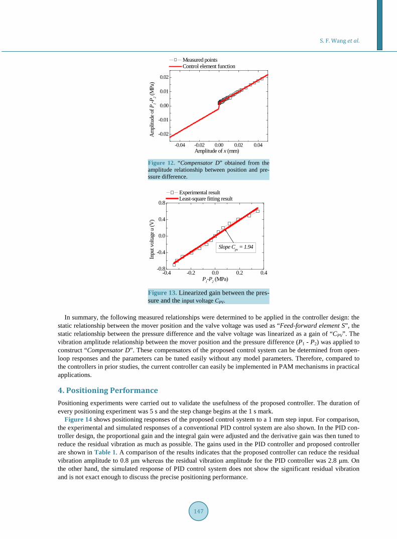
mover displacement, which should be compensated for to allow precise positioning. The amplitude relationship shown in Figure 8 is used as one of the control elements. Figure 12 shows the control element for canceling the nonlinear characteristic, which corresponds to the “Compensator D” in Figure 11. The relationship shown in Figure 12 is expressed in Equation (4). The CPV in Figure 11 is the linearized gain from pressure to input vol-tage shown in Figure 13. The nonlinearity between the input and the output of closed-loop controller is com-pensated for by the “Compensator D” and CPV.
( ) ( )( ) ( )
( ) ( )1 2
0.4 0.002 MPa 1 0.0001 mm
20.4 MPa 0.0001 0.0001 mm
0.4 0.002 MPa 0.0001 1 mm
x x
P P x x
x x
− − < < −
− = − ≤ ≤ + < <
(4)
Step 3: Fine-tuning of the acceleration feedback element The acceleration feedback element is added to further reduce the residual vibration. Since the acceleration is
essentially proportional to the pressure, the output of the acceleration feedback element is connected to the node of the pressure signal.
(mm) (MPa) x(mm)
(MPa)
Acceleration feedback
2
1
+sT
sKd
a
PAM mechanism
x(mm)
Controller switch
algorithm
Yes
No
Has x
reached xr?
(V)
xr(mm)
(V)
Feed-forward element S
(mm)
+ +
PV C - +
+
Compensator D
+
PID compensator
pK
1+sTsK
d
d
sKi
-
+ xr(mm) +
Figure 11. Block diagram of control system for precise positioning of PAM mechanisms.
S. F. Wang et al.
147
-0.04 -0.02 0.00 0.02 0.04
-0.02
-0.01
0.00
0.01
0.02
Ampl
itude
of P
1-P2 (M
Pa)
Amplitude of x (mm)
Measured points Control element function
Figure 12. “Compensator D” obtained from the amplitude relationship between position and pre- ssure difference.
-0.4 -0.2 0.0 0.2 0.4-0.8
-0.4
0.0
0.4
0.8
Slope Cpv = 1.94
Experimental result Least-square fitting result
Inpu
t vol
tage u
(V)
P1-P2 (MPa) Figure 13. Linearized gain between the pres- sure and the input voltage CPV.
In summary, the following measured relationships were determined to be applied in the controller design: the
static relationship between the mover position and the valve voltage was used as “Feed-forward element S”, the static relationship between the pressure difference and the valve voltage was linearized as a gain of “CPV”. The vibration amplitude relationship between the mover position and the pressure difference (P1 - P2) was applied to construct “Compensator D”. These compensators of the proposed control system can be determined from open- loop responses and the parameters can be tuned easily without any model parameters. Therefore, compared to the controllers in prior studies, the current controller can easily be implemented in PAM mechanisms in practical applications.
4. Positioning Performance Positioning experiments were carried out to validate the usefulness of the proposed controller. The duration of every positioning experiment was 5 s and the step change begins at the 1 s mark.
Figure 14 shows positioning responses of the proposed control system to a 1 mm step input. For comparison, the experimental and simulated responses of a conventional PID control system are also shown. In the PID con-troller design, the proportional gain and the integral gain were adjusted and the derivative gain was then tuned to reduce the residual vibration as much as possible. The gains used in the PID controller and proposed controller are shown in Table 1. A comparison of the results indicates that the proposed controller can reduce the residual vibration amplitude to 0.8 μm whereas the residual vibration amplitude for the PID controller was 2.8 μm. On the other hand, the simulated response of PID control system does not show the significant residual vibration and is not exact enough to discuss the precise positioning performance.

S. F. Wang et al.
148
Moreover, in order to explain the effectiveness of “Compensator D”, the step response by the controller with a linearized “Compensator D” is shown in Figure 14 as well. The controller is the same as the result that in the proposed controller, but the “Compensator D” is replaced with a linearized “Compensator D”. It can be found that the vibration amplitude of the proposed control system in steady-state is smaller than that of the control system with a linearized “Compensator D”. The result indicates that the nonlinear “Compensator D” of the pro-posed controller is more effective to reduce the residual vibration in precise positioning.
To examine the influence of the nonlinearity of the PAM, the positioning performance was evaluated at dif-ferent target positions. In the positive direction, positioning experiments with xr = 0.3 mm, 0.5 mm, 0.7 mm and 1 mm were performed and their results are shown in Figure 15. In the negative direction, positioning perfor-mance when xr = −0.5 mm and −1 mm were tested and the results are shown in Figure 16. The proposed con-troller was also evaluated when the target position was the original position xr = 0 mm and the result is shown in Figure 17. In the experiment, the initial position was 1 μm.
The experimental positioning results show that the positioning accuracy decreases with an increase of the dis-tance between the target position and the original position. However the positioning errors are all less than 1 μm in the working range of the PAM mechanism. Table 2 summarizes the averaged maximum steady-state errors and their standard deviations during 3 s to 5 s of 20 positioning experiments. According to the results in Table 2, sub-micrometer order positioning is achieved by the proposed controller. The positioning accuracy and the resi-dual vibration frequency depend on the mover position although the reason is not clear. However, according to the positioning results, the resonant frequency changes with the mover position. The reason of this problem is not clear yet, but it will be clarified as the subject of next step of this research.
Figure 18 shows the resolution test results in different positions. In these figures, Figure 18(c) shows the res-olution test result near xr = 0 mm where we can find that the vibration frequency of the mover is lower than those in Figures 18(a)-(b) Figure 18(d) and Figure 18(e), but similar to Figure 17. According to these res-ponses, a 0.5 μm resolution can be specified.
Figure 14. A comparison of the positioning results of dif-ferent controllers.
Table 1. Controller gains of PID element in two control systems.
Gain PID controller Proposed controller
Kp 1.2 4
Ki 30 40
Kd 0.005 0.15

S. F. Wang et al.
149
(a) (b)
(c) (d)
Figure 15. Positioning results for positive target positions. (a) xr = 0.3 mm; (b) xr = 0.5 mm; (c) xr = 0.7 mm; (d) xr = 1 mm.
(a) (b)
Figure 16. Positioning results for negative target positions. (a) xr = −0.5 mm; (b) xr = −1 mm.
5. Conclusions The practical and effective controller and its design procedure for precise positioning of PAM mechanisms have been proposed and its usefulness has been evaluated experimentally. PAM systems have nonlinear characteris-

S. F. Wang et al.
150
1 2 3 4 5-0.002-0.0010.0000.0010.002
1 2 3-0.001
0.000
0.001
x - 0
(mm
)
Time (s)
0.000.050.100.150.200.250.30
Posit
ion
x (m
m)
Posit
ion
x (m
m)
Time (s)
Figure 17. Positioning results for target position xr = 0 mm.
Table 2. Average and standard deviation of maximum steady-state errors in 20 positioning experiments.
Target position (mm) Average (μm) Standard deviation (μm)
−1 0.880 0.062
−0.5 0.625 0.043
0 0.655 0.059
0.3 0.485 0.035
0.5 0.640 0.049
0.7 0.800 0.032
1 0.850 0.045
tics such as a friction force and a nonlinear air flow dynamic. These characteristics provide the low controllabil-ity and make them difficult to move finely even if a high precision sensor is used.
The introduced conventional nonlinear dynamic model cannot show the same responses as the experimental mechanism microscopically although it provides the reasonable responses macroscopically. The practical con-troller design procedure needs three measured elements but not the model identification. The experimental-ly-measured elements were used in the controller design directly. This feature makes the controller design easy for engineers who are unfamiliar with control engineering. The positioning performance was evaluated experi-mentally. Experimental results demonstrated the effectiveness of the proposed controller with sub-micrometer positioning accuracy and 0.5 μm positioning resolution of the PAM mechanism. Therefore, it can be concluded that the proposed controller with a few nonlinear elements can be easily designed and provides high-precision positioning of PAM mechanisms. According to the positioning results, the positioning accuracy and the residual vibration frequency depend on the mover position. The reason of this problem is not clear yet, but it will be ex-amined as a future work of this research.
The sampling rate of 10 kHz was used because the controller structure in this study was simple and good con-troller hardware was available. In this paper, we did not focus the reduction of the sampling rate. However the large difference between the sampling rate and the frequency of the residual vibration suggests the possibility to reduce it and make lower cost and lower-power controller hardwares useful. Based on the proposed controller design procedure, even though the change of the characteristics makes re-measurement of the input-output rela-tionships necessary for good positioning performance, it is easy to measure the relationships. Furthermore, the compensation of the nonlinear characteristics enables the PD gains to increase and the increase can lead the ro-bustness to the disturbance force. Therefore, the proposed controller design procedure is really reliable on in-dustrial point of view and makes the total positioning system robust.

S. F. Wang et al.
151
0 2 4 6 8 10
0.497
0.498
0.499
0.500
0.501 Position Target posiotion
Posi
tion
x (m
m)
Time (s)
0 2 4 6 8 10
0.997
0.998
0.999
1.000
1.001 Position Target posiotion
Posi
tion
x (m
m)
Time (s) (a) (b)
0 2 4 6 8 10
-0.003
-0.002
-0.001
0.000
0.001 Position Target posiotion
Posi
tion
x (m
m)
Time s
0 2 4 6 8 10-0.501
-0.500
-0.499
-0.498
-0.497
Position Target posiotion
Posi
tion
x (m
m)
Time (s) (c) (d)
0 2 4 6 8 10-1.001
-1.000
-0.999
-0.998
-0.997
Position Target posiotion
Posi
tion
x (m
m)
Time (s) (e)
Figure 18. Resolution test results for different positions. (a) Resolution test results near 0.5 mm; (b) Resolution test results near 1 mm; (c) Resolution test results near 0 mm; (d) Resolution test results near −0.5 mm; (e) Resolu-tion test results near −1 mm.
Although this paper focused on precise positioning, precise tracking control is important in this research. Thus
an important future work is to examine a precise tracking control method and its design procedure for PAM sys-tems based on the proposed controller and achieve high tracking performance of PAM systems.

S. F. Wang et al.
152
References [1] Reynolds, D.B., Repperger, D.W., Phillips, C.A. and Bandry, G. (2003) Modeling the Dynamic Characteristics of
Pneumatic Muscle. Annals of Biomedical Engineering, 31, 310-317. http://dx.doi.org/10.1114/1.1554921 [2] Jouppila, V., Gadsden, S.A. and Ellman, A. (2014) Experimental Comparisons of Sliding Mode Controlled Pneumatic
Muscle and Cylinder Actuators. Journal of Dynamic Systems, Measurement, and Control, 136, Article ID: 044503. http://dx.doi.org/10.1115/1.4026873
[3] Hosoda, K., Takuma, T., Nakamoto, A. and Hayashi, S. (2008) Biped Robot Design Powered by Antagonistic Pneuma- tic Actuators for Multi-Modal Locomotion. Robotics and Autonomous Systems, 56, 46-53. http://dx.doi.org/10.1016/j.robot.2007.09.010
[4] Narioka, K. and Hosoda, K. (2011) Motor Development of a Pneumatic Musculoskeletal Infant Robot. Proceedings of the 2011 IEEE International Conference on Robotics and Automation, Shanghai, 9-13 May 2011, 963-968. http://dx.doi.org/10.1109/icra.2011.5980416
[5] Balasubramanian, S., Ward, J., Sugar, T. and He, J. (2007) Characterization of the Dynamic Properties of Pneumatic-Muscle Actuators. Proceedings of the 2007 IEEE 10th International Conference on Rehabilitation Robotics, Noord-wijk, 12-15 June 2007, 764-770. http://dx.doi.org/10.1109/icorr.2007.4428511
[6] Wong, Z., Teng, C. and Chong, Y. (2012) Power Assisted Pnumatic-Based Knee-Ankle-Foot-Orthosis for Rehabilita-tion. Proceedings of the 2012 IEEE EMBS Conference on Biomedical Engineering and Sciences, Langkawi, 17-19 De- cember 2012, 300-304. http://dx.doi.org/10.1109/iecbes.2012.6498058
[7] Hussain, S., Xie, S.Q. and Jamwal, P.K. (2013) Robust Nonlinear Control of an Intrinsically Compliant Robotic Gait Training Orthosis. IEEE Transactions on Systems, Man, and Cybernetics: Systems, 43, 655-665. http://dx.doi.org/10.1109/tsmca.2012.2207111
[8] Zhu, X., Tao, G., Yao, B. and Cao, J. (2008) Adaptive Robust Posture Control of a Parallel Manipulator Driven by Pneumatic Muscles. Automatica, 44, 2248-2257. http://dx.doi.org/10.1016/j.automatica.2008.01.015
[9] Zhu, X., Tao, G., Yao, B. and Cao, J. (2009) Integrated Direct/Indirect Adaptive Robust Posture Trajectory Tracking Control of a Parallel Manipulator Driven by Pneumatic Muscles. IEEE Transactions on Control Systems Technology, 17, 576-588. http://dx.doi.org/10.1109/tcst.2008.2001715
[10] Wickramatunge, K.C. and Leephakpreeda, T. (2010) Study on Mechanical Behaviors of Pneumatic Artificial Muscle. International Journal of Engineering Science, 48, 188-198. http://dx.doi.org/10.1016/j.ijengsci.2009.08.001
[11] Minh, T.V., Kamers, B., Ramon, H. and Brussel, H.V. (2012) Modeling and Control of a Pneumatic Artificial Muscle Manipulator Joint-Part I: Modeling of a Pneumatic Artificial Muscle Manipulator Joint with Accounting for Creep Ef-fect. Mechatronics, 22, 923-933. http://dx.doi.org/10.1016/j.mechatronics.2012.06.002
[12] Vo-Minh, T., Tjahjowidodo, T., Ramon, H. and Brussel, H.V. (2011) A New Approach to Modeling Hysteresis in a Pneumatic Artificial Muscle Using the Maxwell-Slip Model. IEEE/ASME Transactions on Mechatronics, 16, 177-186. http://dx.doi.org/10.1109/tmech.2009.2038373
[13] Raoufi, C., Goldenberg, A.A. and Kucharczyk, W. (2008) A New Hydraulically/Pneumatically Actuated MR-Compa- tible Robot for MRI-Guided Neurosurgery. Proceedings of the 2nd International Conference on Bioinformatics and Bi- omedical Engineering, Shanghai, 16-18 May 2008, 2232-3335. http://dx.doi.org/10.1109/icbbe.2008.889
[14] Pujana-Arrese, A., Mendizabal, A., Arenas, J., Prestamero, R. and Landaluze, J. (2010) Modelling in Modelica and Po-sition Control of a 1-DoF Set-Up Poweredby Pneumatic Muscles. Mechatronics, 20, 535-552. http://dx.doi.org/10.1016/j.mechatronics.2010.05.002
[15] Li, X., He, F., Xia, H. and Ting, G. (2012) Implicit Generalized Predictive Control of Hip-Joint Rehabilitation Training Device Driven by Pneumatic Muscle Actuator. Applied Mechanics and Materials, 138-139, 273-278. http://dx.doi.org/10.4028/www.scientific.net/amm.138-139.273
[16] Andrikopoulos, G., Nikolakopoulos, G. and Manesis, S. (2013) Non-Linear Control of Pneumatic Artificial Muscles. Proceeding of the 21st Mediterranean Conference on Control & Automation, Chania, 25-28 June 2013, 729-734. http://dx.doi.org/10.1109/med.2013.6608804
[17] Tondu, B. and Lopez, P. (2000) Modeling and Control of McKibben Artificial Muscle Robot Actuators. IEEE Control Systems, 20, 15-38. http://dx.doi.org/10.1109/37.833638
[18] Xing, K., Huang, J., Wang, Y., Wu, J., Xu, Q. and He, J. (2010) Tracking Control of Pneumatic Artificial Muscle Ac-tuators Based on Sliding Mode and Non-linear Disturbance Observer. Control Theory & Applications, 4, 2058-2070. http://dx.doi.org/10.1049/iet-cta.2009.0555
[19] Yang, L. and Lilly, H.L. (2003) Sliding Mode Tracking for Pneumatic Muscle Actuators in Bicep/Tricep Pair Configu- ration. Proceedings of the 2003 American Control Conference, Denver, 4-6 June 2003, 4669-4674. http://dx.doi.org/10.1109/acc.2003.1242460

S. F. Wang et al.
153
[20] Choi, T. and Lee, J. (2010) Control of Manipulator Using Pneumatic Muscles for Enhanced Safety. IEEE Transactions on Industrial Electronics, 57, 2815-2825. http://dx.doi.org/10.1109/tie.2009.2036632
[21] Li, H., Kawashima, K., Tadano, K., Ganguly, S. and Nakano, S. (2013) Achieving Haptic Perception in Forceps’ Mani- pulator Using Pneumatic Artificial Muscle. IEEE/ASME Transactions on Mechatronics, 18, 74-85. http://dx.doi.org/10.1109/tmech.2011.2163415
[22] Lilly, J.H. (2003) Adaptive Tracking for Pneumatic Muscle Actuators in Bicep and Tricep Configurations. IEEE Transactions on Neural Systems and Rehabilitation Engineering, 11, 333-339. http://dx.doi.org/10.1109/TNSRE.2003.816870
[23] Chang, M., Liou, J. and Chen, M. (2011) T-S Fuzzy Model-Based Tracking Control of a One-Dimensional Manipula-tor Actuated by Pneumatic Artificial Muscles. Control Engineering Practice, 19, 1442-1449. http://dx.doi.org/10.1016/j.conengprac.2011.08.002
[24] Leephakpreeda, T. (2011) Fuzzy Logic Based PWM Control and Neural Controlled-Variable Estimation of Pneumatic Artificial Muscle Actuators. Expert Systems with Applications, 38, 7837-7850. http://dx.doi.org/10.1016/j.eswa.2010.12.120
[25] Ahn, K.K., Thanh, T.D.C. and Ahn, Y.K. (2005) Intelligent Switching Control of Pneumatic Artificial Muscle Manipu- lator. JSME International Journal Series C Mechanical Systems, Machine Elements and Manufacturing, 48, 657-667. http://dx.doi.org/10.1299/jsmec.48.657
[26] Sato, K. and Sano, Y. (2014) Practical and Intuitive Controller Design Method for Precision Positioning of a Pneumat-ic Cylinder Actuator Stage. Precision Engineering, 38, 703-710. http://dx.doi.org/10.1016/j.precisioneng.2014.03.006
[27] Shen, X. (2010) Nonlinear Model-Based Control of Pneumatic Artificial Muscle Servo Systems. Control Engineering Practice, 18, 311-317. http://dx.doi.org/10.1016/j.conengprac.2009.11.010
[28] Chou, C. and Hannaford, B. (1996) Measurement and Modeling of McKibben Pneumatic Artificial Muscles. IEEE Transactions on Robotics and Automation, 12, 90-102. http://dx.doi.org/10.1109/70.481753
[29] Ganguly, S., Garg, A., Pasricha, A. and Dwivedy, S.K. (2012) Control of Pneumatic Artificial Muscle System through Experimental Modelling. Mechatronics, 22, 1135-1147. http://dx.doi.org/10.1016/j.mechatronics.2012.09.010
[30] Festo (2010) Fluidic Muscle DMSP/MAS. Festo Brochure. https://www.festo.com/cat/ja_jp/data/doc_engb/PDF/EN/DMSP-MAS_EN.PDF
[31] Fliess, M., Levine, J., Martin, P. and Rouchon, P. (1999) A Lie-Backlund Approach to Equivalence and Flatness of Nonlinear Systems. IEEE Transactions on Automatic Control, 44, 922-937. http://dx.doi.org/10.1109/9.763209
[32] Fliess, M. and Join, C. (2008) Intelligent PID Controllers. 16th Mediterranean Conference on Control and Automation, Ajaccio, 25-27 June 2008, 326-331.


![By David Torgesen. [1] Wikipedia contributors. "Pneumatic artificial muscles." Wikipedia, The Free Encyclopedia. Wikipedia, The Free Encyclopedia, 3 Feb](https://img.pdfslide.net/doc/110x75/5519c0e055034660578b4b80/by-david-torgesen-1-wikipedia-contributors-pneumatic-artificial-muscles-wikipedia-the-free-encyclopedia-wikipedia-the-free-encyclopedia-3-feb.jpg)