Embed Size (px)
Citation preview
1FEATURES
APPLICATIONS
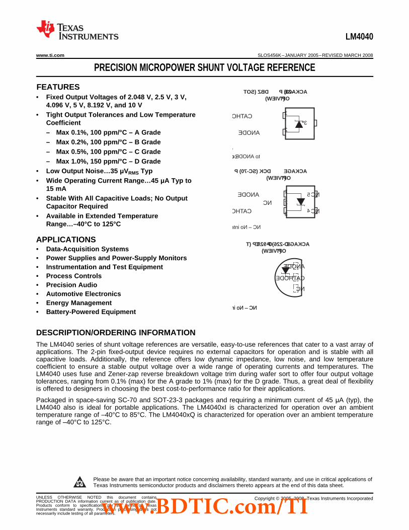
* Pin 3 is attached to substrate and must beconnected to ANODE or left open.
DBZ (SOT -23) P ACKAGE(T OP VIEW)
CATHODE
ANODE
DCK (SC-70) P ACKAGE(T OP VIEW)
ANODENC
CATHODE
NC
NC
1
23*
1
2
3
5
4
NC
CATHODE
ANODE
LP (T O-92/T O-226) P ACKAGE(T OP VIEW)
NC – No internal connection NC – No internal connection
NC – No internal connection
DESCRIPTION/ORDERING INFORMATION
LM4040
www.ti.com .................................................................................................................................................. SLOS456K–JANUARY 2005–REVISED MARCH 2008
PRECISION MICROPOWER SHUNT VOLTAGE REFERENCE
• Fixed Output Voltages of 2.048 V, 2.5 V, 3 V,4.096 V, 5 V, 8.192 V, and 10 V
• Tight Output Tolerances and Low TemperatureCoefficient– Max 0.1%, 100 ppm/°C – A Grade– Max 0.2%, 100 ppm/°C – B Grade– Max 0.5%, 100 ppm/°C – C Grade– Max 1.0%, 150 ppm/°C – D Grade
• Low Output Noise…35 μVRMS Typ• Wide Operating Current Range…45 μA Typ to
15 mA• Stable With All Capacitive Loads; No Output
Capacitor Required• Available in Extended Temperature
Range…–40°C to 125°C
• Data-Acquisition Systems• Power Supplies and Power-Supply Monitors• Instrumentation and Test Equipment• Process Controls• Precision Audio• Automotive Electronics• Energy Management• Battery-Powered Equipment
The LM4040 series of shunt voltage references are versatile, easy-to-use references that cater to a vast array ofapplications. The 2-pin fixed-output device requires no external capacitors for operation and is stable with allcapacitive loads. Additionally, the reference offers low dynamic impedance, low noise, and low temperaturecoefficient to ensure a stable output voltage over a wide range of operating currents and temperatures. TheLM4040 uses fuse and Zener-zap reverse breakdown voltage trim during wafer sort to offer four output voltagetolerances, ranging from 0.1% (max) for the A grade to 1% (max) for the D grade. Thus, a great deal of flexibilityis offered to designers in choosing the best cost-to-performance ratio for their applications.
Packaged in space-saving SC-70 and SOT-23-3 packages and requiring a minimum current of 45 μA (typ), theLM4040 also is ideal for portable applications. The LM4040xI is characterized for operation over an ambienttemperature range of –40°C to 85°C. The LM4040xQ is characterized for operation over an ambient temperaturerange of –40°C to 125°C.
1
Please be aware that an important notice concerning availability, standard warranty, and use in critical applications ofTexas Instruments semiconductor products and disclaimers thereto appears at the end of this data sheet.
UNLESS OTHERWISE NOTED this document contains Copyright © 2005–2008, Texas Instruments IncorporatedPRODUCTION DATA information current as of publication date.Products conform to specifications per the terms of TexasInstruments standard warranty. Production processing does notnecessarily include testing of all parameters.www.BDTIC.com/TI

LM4040
SLOS456K–JANUARY 2005–REVISED MARCH 2008 .................................................................................................................................................. www.ti.com
ORDERING INFORMATION (1)
DEVICE ORDERABLE TOP-SIDETA VKA PACKAGE (2)GRADE PART NUMBER MARKING (3)
SC-70 (DCK) Reel of 3000 LM4040A20IDCKR MS_Reel of 3000 LM4040A20IDBZR
SOT-23-3 (DBZ) 4MC_2.048 V Reel of 250 LM4040A20IDBZT
Bulk of 1000 LM4040A20ILPTO-92/TO-226 (LP) PREVIEW
Reel of 2000 LM4040A20ILPRSC-70 (DCK) Reel of 3000 LM4040A25IDCKR P2_
Reel of 3000 LM4040A25IDBZRSOT-23-3 (DBZ) 4NG_
2.5 V Reel of 250 LM4040A25IDBZTBulk of 1000 LM4040A25ILP
TO-92/TO-226 (LP) PREVIEWReel of 2000 LM4040A25ILPR
SC-70 (DCK) Reel of 3000 LM4040A30IDCKR P9_Reel of 3000 LM4040A30IDBZR
SOT-23-3 (DBZ) 4M6_3 V Reel of 250 LM4040A30IDBZT
Bulk of 1000 LM4040A30ILPTO-92/TO-226 (LP) PREVIEW
Reel of 2000 LM4040A30ILPRA grade: SC-70 (DCK) Reel of 3000 LM4040A41IDCKR P4_
0.1% initial Reel of 3000 LM4040A41IDBZRaccuracy SOT-23-3 (DBZ) 4M2_–40°C to 85°C and 4.096 V Reel of 250 LM4040A41IDBZT
100 ppm/°C Bulk of 1000 LM4040A41ILPtemperature TO-92/TO-226 (LP) PREVIEWReel of 2000 LM4040A41ILPRcoefficient
SC-70 (DCK) Reel of 3000 LM4040A50IDCKR N5_Reel of 3000 LM4040A50IDBZR
SOT-23-3 (DBZ) 4NA_5 V Reel of 250 LM4040A50IDBZT
Bulk of 1000 LM4040A50ILPTO-92/TO-226 (LP) PREVIEW
Reel of 2000 LM4040A50ILPRSC-70 (DCK) Reel of 3000 LM4040A82IDCKR PD_
Reel of 3000 LM4040A82IDBZRSOT-23-3 (DBZ) 4NL_
8.192 V Reel of 250 LM4040A82IDBZTBulk of 1000 LM4040A82ILP
TO-92/TO-226 (LP) PREVIEWReel of 2000 LM4040A82ILPR
SC-70 (DCK) Reel of 3000 LM4040A10IDCKR PH_Reel of 3000 LM4040A10IDBZR
SOT-23-3 (DBZ) 4NQ_10 V Reel of 250 LM4040A10IDBZT
Bulk of 1000 LM4040A10ILPTO-92/TO-226 (LP) PREVIEW
Reel of 2000 LM4040A10ILPR
(1) For the most current package and ordering information, see the Package Option Addendum at the end of this document, or see the TIweb site at www.ti.com.
(2) Package drawings, thermal data, and symbolization are available at www.ti.com/packaging.(3) DBZ/DCK: The actual top-side marking has one additional character that designates the wafer fab/assembly site.
2 Submit Documentation Feedback Copyright © 2005–2008, Texas Instruments Incorporatedwww.BDTIC.com/TI
LM4040
www.ti.com .................................................................................................................................................. SLOS456K–JANUARY 2005–REVISED MARCH 2008
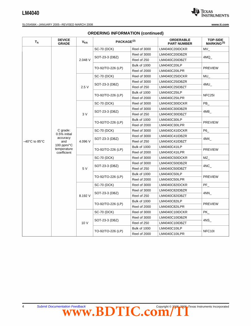
ORDERING INFORMATION (continued)DEVICE ORDERABLE TOP-SIDETA VKA PACKAGE (2)GRADE PART NUMBER MARKING (3)
SC-70 (DCK) Reel of 3000 LM4040B20IDCKR MT_Reel of 3000 LM4040B20IDBZR
SOT-23-3 (DBZ) 4MD_2.048 V Reel of 250 LM4040B20IDBZT
Bulk of 1000 LM4040B20ILPTO-92/TO-226 (LP) PREVIEW
Reel of 2000 LM4040B20ILPRSC-70 (DCK) Reel of 3000 LM4040B25IDCKR P3_
Reel of 3000 LM4040B25IDBZRSOT-23-3 (DBZ) 4NH_
2.5 V Reel of 250 LM4040B25IDBZTBulk of 1000 LM4040B25ILP
TO-92/TO-226 (LP) PREVIEWReel of 2000 LM4040B25ILPR
SC-70 (DCK) Reel of 3000 LM4040B30IDCKR PA_Reel of 3000 LM4040B30IDBZR
SOT-23-3 (DBZ) 4M7_3 V Reel of 250 LM4040B30IDBZT
Bulk of 1000 LM4040B30ILPTO-92/TO-226 (LP) PREVIEW
Reel of 2000 LM4040B30ILPRB grade: SC-70 (DCK) Reel of 3000 LM4040B41IDCKR P5_
0.2% initial Reel of 3000 LM4040B41IDBZRaccuracy SOT-23-3 (DBZ) 4M3_–40°C to 85°C and 4.096 V Reel of 250 LM4040B41IDBZT
100 ppm/°C Bulk of 1000 LM4040B41ILPtemperature TO-92/TO-226 (LP) PREVIEWReel of 2000 LM4040B41ILPRcoefficient
SC-70 (DCK) Reel of 3000 LM4040B50IDCKR MX_Reel of 3000 LM4040B50IDBZR
SOT-23-3 (DBZ) 4NB_5 V Reel of 250 LM4040B50IDBZT
Bulk of 1000 LM4040B50ILPTO-92/TO-226 (LP) PREVIEW
Reel of 2000 LM4040B50ILPRSC-70 (DCK) Reel of 3000 LM4040B82IDCKR PE_
Reel of 3000 LM4040B82IDBZRSOT-23-3 (DBZ) 4NM_
8.192 V Reel of 250 LM4040B82IDBZTBulk of 1000 LM4040B82ILP
TO-92/TO-226 (LP) PREVIEWReel of 2000 LM4040B82ILPR
SC-70 (DCK) Reel of 3000 LM4040B10IDCKR PJ_Reel of 3000 LM4040B10IDBZR
SOT-23-3 (DBZ) 4NR_10 V Reel of 250 LM4040B10IDBZT
Bulk of 1000 LM4040B10ILPTO-92/TO-226 (LP) PREVIEW
Reel of 2000 LM4040B10ILPR
Copyright © 2005–2008, Texas Instruments Incorporated Submit Documentation Feedback 3www.BDTIC.com/TI
LM4040
SLOS456K–JANUARY 2005–REVISED MARCH 2008 .................................................................................................................................................. www.ti.com
ORDERING INFORMATION (continued)DEVICE ORDERABLE TOP-SIDETA VKA PACKAGE (2)GRADE PART NUMBER MARKING (3)
SC-70 (DCK) Reel of 3000 LM4040C20IDCKR MV_Reel of 3000 LM4040C20IDBZR
SOT-23-3 (DBZ) 4MQ_2.048 V Reel of 250 LM4040C20IDBZT
Bulk of 1000 LM4040C20ILPTO-92/TO-226 (LP) PREVIEW
Reel of 2000 LM4040C20ILPRSC-70 (DCK) Reel of 3000 LM4040C25IDCKR MU_
Reel of 3000 LM4040C25IDBZRSOT-23-3 (DBZ) 4MU_
2.5 V Reel of 250 LM4040C25IDBZTBulk of 1000 LM4040C25ILP
TO-92/TO-226 (LP) NFC25IReel of 2000 LM4040C25ILPR
SC-70 (DCK) Reel of 3000 LM4040C30IDCKR PB_Reel of 3000 LM4040C30IDBZR
SOT-23-3 (DBZ) 4M8_3 V Reel of 250 LM4040C30IDBZT
Bulk of 1000 LM4040C30ILPTO-92/TO-226 (LP) PREVIEW
Reel of 2000 LM4040C30ILPRC grade: SC-70 (DCK) Reel of 3000 LM4040C41IDCKR P6_
0.5% initial Reel of 3000 LM4040C41IDBZRaccuracy SOT-23-3 (DBZ) 4M4_–40°C to 85°C and 4.096 V Reel of 250 LM4040C41IDBZT
100 ppm/°C Bulk of 1000 LM4040C41ILPtemperature TO-92/TO-226 (LP) PREVIEWReel of 2000 LM4040C41ILPRcoefficient
SC-70 (DCK) Reel of 3000 LM4040C50IDCKR MZ_Reel of 3000 LM4040C50IDBZR
SOT-23-3 (DBZ) 4NC_5 V Reel of 250 LM4040C50IDBZT
Bulk of 1000 LM4040C50ILPTO-92/TO-226 (LP) PREVIEW
Reel of 2000 LM4040C50ILPRSC-70 (DCK) Reel of 3000 LM4040C82IDCKR PF_
Reel of 3000 LM4040C82IDBZRSOT-23-3 (DBZ) 4NN_
8.192 V Reel of 250 LM4040C82IDBZTBulk of 1000 LM4040C82ILP
TO-92/TO-226 (LP) PREVIEWReel of 2000 LM4040C82ILPR
SC-70 (DCK) Reel of 3000 LM4040C10IDCKR PK_Reel of 3000 LM4040C10IDBZR
SOT-23-3 (DBZ) 4NS_10 V Reel of 250 LM4040C10IDBZT
Bulk of 1000 LM4040C10ILPTO-92/TO-226 (LP) NFC10I
Reel of 2000 LM4040C10ILPR
4 Submit Documentation Feedback Copyright © 2005–2008, Texas Instruments Incorporatedwww.BDTIC.com/TI

LM4040
www.ti.com .................................................................................................................................................. SLOS456K–JANUARY 2005–REVISED MARCH 2008
ORDERING INFORMATION (continued)DEVICE ORDERABLE TOP-SIDETA VKA PACKAGE (2)GRADE PART NUMBER MARKING (3)
SC-70 (DCK) Reel of 3000 LM4040D20IDCKR MW_Reel of 3000 LM4040D20IDBZR
SOT-23-3 (DBZ) 4MV_2.048 V Reel of 250 LM4040D20IDBZT
Bulk of 1000 LM4040D20ILPTO-92/TO-226 (LP) PREVIEW
Reel of 2000 LM4040D20ILPRSC-70 (DCK) Reel of 3000 LM4040D25IDCKR ME_
Reel of 3000 LM4040D25IDBZRSOT-23-3 (DBZ) 4ME_
2.5 V Reel of 250 LM4040D25IDBZTBulk of 1000 LM4040D25ILP
TO-92/TO-226 (LP) NFD25IReel of 2000 LM4040D25ILPR
SC-70 (DCK) Reel of 3000 LM4040D30IDCKR PC_Reel of 3000 LM4040D30IDBZR
SOT-23-3 (DBZ) 4M9_3 V Reel of 250 LM4040D30IDBZT
Bulk of 1000 LM4040D30ILPTO-92/TO-226 (LP) PREVIEW
Reel of 2000 LM4040D30ILPRD grade: SC-70 (DCK) Reel of 3000 LM4040D41IDCKR P7_
1.0% initial Reel of 3000 LM4040D41IDBZRaccuracy SOT-23-3 (DBZ) 4M5_–40°C to 85°C and 4.096 V Reel of 250 LM4040D41IDBZT
150 ppm/°C Bulk of 1000 LM4040D41ILPtemperature TO-92/TO-226 (LP) PREVIEWReel of 2000 LM4040D41ILPRcoefficient
SC-70 (DCK) Reel of 3000 LM4040D50IDCKR M4_Reel of 3000 LM4040D50IDBZR
SOT-23-3 (DBZ) 4ND_5 V Reel of 250 LM4040D50IDBZT
Bulk of 1000 LM4040D50ILPTO-92/TO-226 (LP) PREVIEW
Reel of 2000 LM4040D50ILPRSC-70 (DCK) Reel of 3000 LM4040D82IDCKR PG_
Reel of 3000 LM4040D82IDBZRSOT-23-3 (DBZ) 4NP_
8.192 V Reel of 250 LM4040D82IDBZTBulk of 1000 LM4040D82ILP
TO-92/TO-226 (LP) PREVIEWReel of 2000 LM4040D82ILPR
SC-70 (DCK) Reel of 3000 LM4040D10IDCKR PL_Reel of 3000 LM4040D10IDBZR
SOT-23-3 (DBZ) 4NT_10 V Reel of 250 LM4040D10IDBZT
Bulk of 1000 LM4040D10ILPTO-92/TO-226 (LP) NFD10I
Reel of 2000 LM4040D10ILPR
Copyright © 2005–2008, Texas Instruments Incorporated Submit Documentation Feedback 5www.BDTIC.com/TI

LM4040
SLOS456K–JANUARY 2005–REVISED MARCH 2008 .................................................................................................................................................. www.ti.com
ORDERING INFORMATION (continued)DEVICE ORDERABLE TOP-SIDETA VKA PACKAGE (2)GRADE PART NUMBER MARKING (3)
Reel of 3000 LM4040C20QDBZR2.048 V 4MW_
Reel of 250 LM4040C20QDBZTC grade:
Reel of 3000 LM4040C25QDBZR0.5% initial 2.5 V 4MA_accuracy Reel of 250 LM4040C25QDBZTand SOT-23-3 (DBZ)
Reel of 3000 LM4040C30QDBZR100 ppm/°C 3 V 4NJ_temperature Reel of 250 LM4040C30QDBZTcoefficient
Reel of 3000 LM4040C50QDBZR5 V 4NE_
Reel of 250 LM4040C50QDBZT–40°C to 125°C
Reel of 3000 LM4040D20QDBZR2.048 V 4MY_
Reel of 250 LM4040D20QDBZTD grade:
Reel of 3000 LM4040D25QDBZR1.0% initial 2.5 V 4MB_accuracy Reel of 250 LM4040D25QDBZTand SOT-23-3 (DBZ)
Reel of 3000 LM4040D30QDBZR150 ppm/°C 3 V 4NK_temperature Reel of 250 LM4040D30QDBZTcoefficient
Reel of 3000 LM4040D50QDBZR5 V 4NF_
Reel of 250 LM4040D50QDBZT
6 Submit Documentation Feedback Copyright © 2005–2008, Texas Instruments Incorporatedwww.BDTIC.com/TI
CATHODE
ANODE
_+
Absolute Maximum Ratings (1)
Recommended Operating Conditions
LM4040
www.ti.com .................................................................................................................................................. SLOS456K–JANUARY 2005–REVISED MARCH 2008
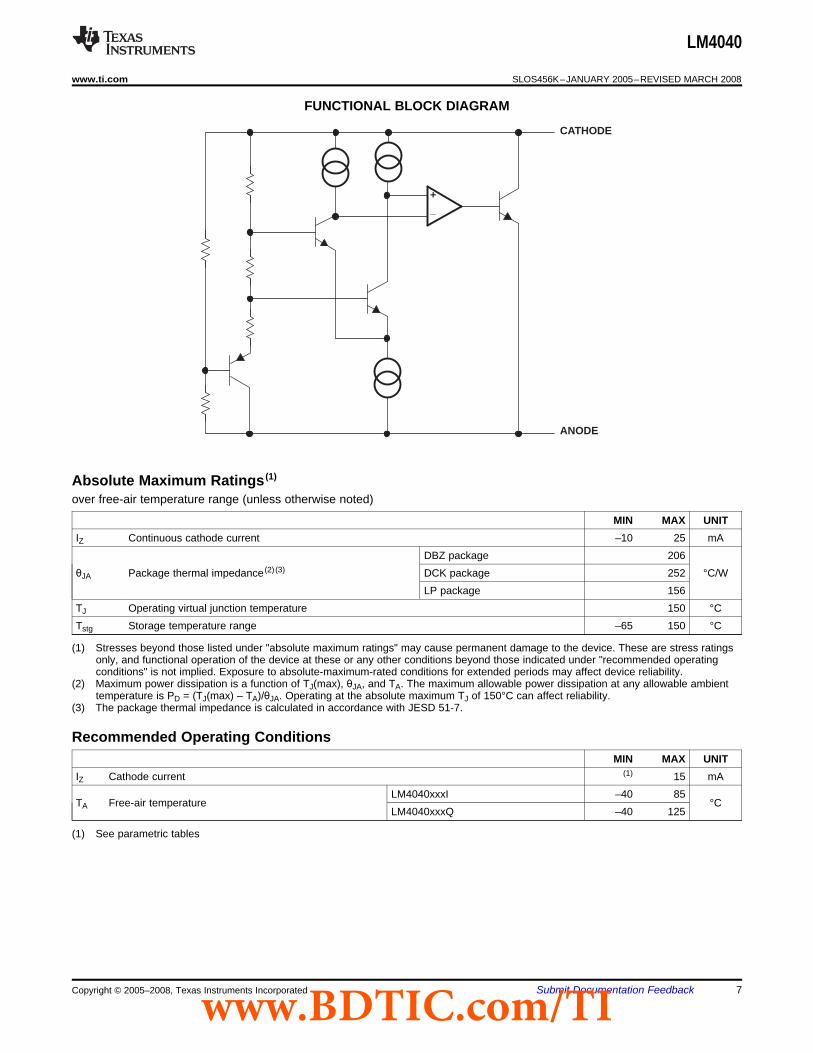
FUNCTIONAL BLOCK DIAGRAM
over free-air temperature range (unless otherwise noted)
MIN MAX UNITIZ Continuous cathode current –10 25 mA
DBZ package 206θJA Package thermal impedance (2) (3) DCK package 252 °C/W
LP package 156TJ Operating virtual junction temperature 150 °CTstg Storage temperature range –65 150 °C
(1) Stresses beyond those listed under "absolute maximum ratings" may cause permanent damage to the device. These are stress ratingsonly, and functional operation of the device at these or any other conditions beyond those indicated under "recommended operatingconditions" is not implied. Exposure to absolute-maximum-rated conditions for extended periods may affect device reliability.
(2) Maximum power dissipation is a function of TJ(max), θJA, and TA. The maximum allowable power dissipation at any allowable ambienttemperature is PD = (TJ(max) – TA)/θJA. Operating at the absolute maximum TJ of 150°C can affect reliability.
(3) The package thermal impedance is calculated in accordance with JESD 51-7.
MIN MAX UNITIZ Cathode current (1) 15 mA
LM4040xxxI –40 85TA Free-air temperature °C
LM4040xxxQ –40 125
(1) See parametric tables
Copyright © 2005–2008, Texas Instruments Incorporated Submit Documentation Feedback 7www.BDTIC.com/TI

LM4040x20I Electrical Characteristics
VZIZ
LM4040
SLOS456K–JANUARY 2005–REVISED MARCH 2008 .................................................................................................................................................. www.ti.com
at industrial temperature range, full-range TA = –40°C to 85°C (unless otherwise noted)
LM4040A20I LM4040B20IPARAMETER TEST CONDITIONS TA UNIT
MIN TYP MAX MIN TYP MAXVZ Reverse breakdown voltage IZ = 100 μA 25°C 2.048 2.048 V
25°C –2 2 –4.1 4.1Reverse breakdown voltageΔVZ IZ = 100 μA mVtolerance Full range –15 15 –17 1725°C 45 75 45 75
IZ,min Minimum cathode current μAFull range 80 80
IZ = 10 mA 25°C ±20 ±2025°C ±15 ±15Average temperature coefficientαVZ IZ = 1 mA ppm/°Cof reverse breakdown voltage Full range ±100 ±100
IZ = 100 μA 25°C ±15 ±1525°C 0.3 0.8 0.3 0.8
IZ,min < IZ < 1 mAReverse breakdown voltage Full range 1 1change with cathode current mV
25°C 2.5 6 2.5 6change 1 mA < IZ < 15 mAFull range 8 8
IZ = 1 mA, f = 120 Hz,ZZ Reverse dynamic impedance 25°C 0.3 0.8 0.3 0.8 ΩIAC = 0.1 IZIZ = 100 μA,eN Wideband noise 25°C 35 35 μVRMS10 Hz ≤ f ≤ 10 kHzt = 1000 h,Long-term stability of reverse TA = 25°C ± 0.1°C, 120 120 ppmbreakdown voltage IZ = 100 μA
VHYST Thermal hysteresis (1) ΔTA = –40°C to 125°C 0.08 0.08 %
(1) Thermal hysteresis is defined as VZ,25°C (after cycling to –40°C) – VZ,25°C (after cycling to 125°C).
8 Submit Documentation Feedback Copyright © 2005–2008, Texas Instruments Incorporatedwww.BDTIC.com/TI

LM4040x20I Electrical Characteristics
VZIZ
LM4040
www.ti.com .................................................................................................................................................. SLOS456K–JANUARY 2005–REVISED MARCH 2008
at industrial temperature range, full-range TA = –40°C to 85°C (unless otherwise noted)
LM4040C20I LM4040D20IPARAMETER TEST CONDITIONS TA UNIT
MIN TYP MAX MIN TYP MAXVZ Reverse breakdown voltage IZ = 100 μA 25°C 2.048 2.048 V
25°C –10 10 –20 20Reverse breakdown voltageΔVZ IZ = 100 μA mVtolerance Full range –23 23 –40 4025°C 45 75 45 75
IZ,min Minimum cathode current μAFull range 80 80
IZ = 10 mA 25°C ±20 ±2025°C ±15 ±15Average temperature coefficientαVZ IZ = 1 mA ppm/°Cof reverse breakdown voltage Full range ±100 ±150
IZ = 100 μA 25°C ±15 ±1525°C 0.3 0.8 0.3 1
IZ,min < IZ < 1 mAReverse breakdown voltage Full range 1 1.2change with cathode current mV
25°C 2.5 6 2.5 8change 1 mA < IZ < 15 mAFull range 8 10
IZ = 1 mA, f = 120 Hz,ZZ Reverse dynamic impedance 25°C 0.3 0.9 0.3 1.1 ΩIAC = 0.1 IZIZ = 100 μA,eN Wideband noise 25°C 35 35 μVRMS10 Hz ≤ f ≤ 10 kHzt = 1000 h,Long-term stability of reverse TA = 25°C ± 0.1°C, 120 120 ppmbreakdown voltage IZ = 100 μA
VHYST Thermal hysteresis (1) ΔTA = –40°C to 125°C 0.08 0.08 %
(1) Thermal hysteresis is defined as VZ,25°C (after cycling to –40°C) – VZ,25°C (after cycling to 125°C).
Copyright © 2005–2008, Texas Instruments Incorporated Submit Documentation Feedback 9www.BDTIC.com/TI
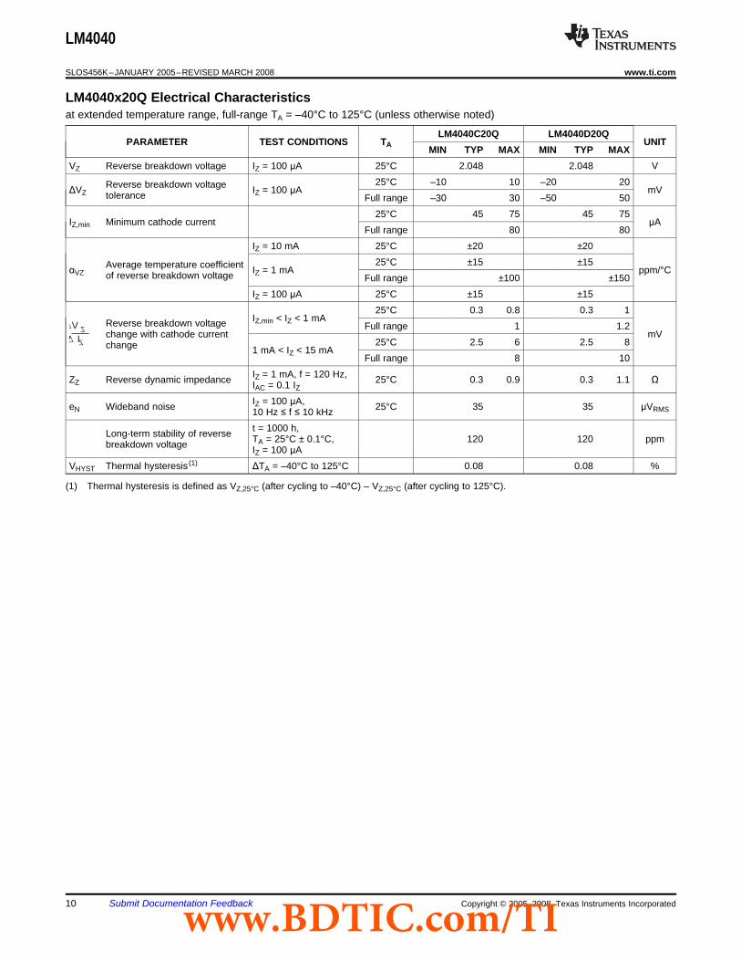
LM4040x20Q Electrical Characteristics
VZIZ
LM4040
SLOS456K–JANUARY 2005–REVISED MARCH 2008 .................................................................................................................................................. www.ti.com
at extended temperature range, full-range TA = –40°C to 125°C (unless otherwise noted)
LM4040C20Q LM4040D20QPARAMETER TEST CONDITIONS TA UNIT
MIN TYP MAX MIN TYP MAXVZ Reverse breakdown voltage IZ = 100 μA 25°C 2.048 2.048 V
25°C –10 10 –20 20Reverse breakdown voltageΔVZ IZ = 100 μA mVtolerance Full range –30 30 –50 5025°C 45 75 45 75
IZ,min Minimum cathode current μAFull range 80 80
IZ = 10 mA 25°C ±20 ±2025°C ±15 ±15Average temperature coefficientαVZ IZ = 1 mA ppm/°Cof reverse breakdown voltage Full range ±100 ±150
IZ = 100 μA 25°C ±15 ±1525°C 0.3 0.8 0.3 1
IZ,min < IZ < 1 mAReverse breakdown voltage Full range 1 1.2change with cathode current mV
25°C 2.5 6 2.5 8change 1 mA < IZ < 15 mAFull range 8 10
IZ = 1 mA, f = 120 Hz,ZZ Reverse dynamic impedance 25°C 0.3 0.9 0.3 1.1 ΩIAC = 0.1 IZIZ = 100 μA,eN Wideband noise 25°C 35 35 μVRMS10 Hz ≤ f ≤ 10 kHzt = 1000 h,Long-term stability of reverse TA = 25°C ± 0.1°C, 120 120 ppmbreakdown voltage IZ = 100 μA
VHYST Thermal hysteresis (1) ΔTA = –40°C to 125°C 0.08 0.08 %
(1) Thermal hysteresis is defined as VZ,25°C (after cycling to –40°C) – VZ,25°C (after cycling to 125°C).
10 Submit Documentation Feedback Copyright © 2005–2008, Texas Instruments Incorporatedwww.BDTIC.com/TI

LM4040x25I Electrical Characteristics
VZIZ
LM4040
www.ti.com .................................................................................................................................................. SLOS456K–JANUARY 2005–REVISED MARCH 2008
at industrial temperature range, full-range TA = –40°C to 85°C (unless otherwise noted)
LM4040A25I LM4040B25IPARAMETER TEST CONDITIONS TA UNIT
MIN TYP MAX MIN TYP MAXVZ Reverse breakdown voltage IZ = 100 μA 25°C 2.5 2.5 V
25°C –2.5 2.5 –5 5Reverse breakdown voltageΔVZ IZ = 100 μA mVtolerance Full range –19 19 –21 2125°C 45 75 45 75
IZ,min Minimum cathode current μAFull range 80 80
IZ = 10 mA 25°C ±20 ±2025°C ±15 ±15Average temperature coefficientαVZ IZ = 1 mA ppm/°Cof reverse breakdown voltage Full range ±100 ±100
IZ = 100 μA 25°C ±15 ±1525°C 0.3 0.8 0.3 0.8
IZ,min < IZ < 1 mAReverse breakdown voltage Full range 1 1change with cathode current mV
25°C 2.5 6 2.5 6change 1 mA < IZ < 15 mAFull range 8 8
IZ = 1 mA, f = 120 Hz,ZZ Reverse dynamic impedance 25°C 0.3 0.8 0.3 0.8 ΩIAC = 0.1 IZIZ = 100 μA,eN Wideband noise 25°C 35 35 μVRMS10 Hz ≤ f ≤ 10 kHzt = 1000 h,Long-term stability of reverse TA = 25°C ± 0.1°C, 120 120 ppmbreakdown voltage IZ = 100 μA
VHYST Thermal hysteresis (1) ΔTA = –40°C to 125°C 0.08 0.08 %
(1) Thermal hysteresis is defined as VZ,25°C (after cycling to –40°C) – VZ,25°C (after cycling to 125°C).
Copyright © 2005–2008, Texas Instruments Incorporated Submit Documentation Feedback 11www.BDTIC.com/TI

LM4040x25I Electrical Characteristics
VZIZ
LM4040
SLOS456K–JANUARY 2005–REVISED MARCH 2008 .................................................................................................................................................. www.ti.com
at industrial temperature range, full-range TA = –40°C to 85°C (unless otherwise noted)
LM4040C25I LM4040D25IPARAMETER TEST CONDITIONS TA UNIT
MIN TYP MAX MIN TYP MAXVZ Reverse breakdown voltage IZ = 100 μA 25°C 2.5 2.5 V
25°C –12 12 –25 25Reverse breakdown voltageΔVZ IZ = 100 μA mVtolerance Full range –29 29 –49 4925°C 45 75 45 75
IZ,min Minimum cathode current μAFull range 80 80
IZ = 10 mA 25°C ±20 ±2025°C ±15 ±15Average temperature coefficientαVZ IZ = 1 mA ppm/°Cof reverse breakdown voltage Full range ±100 ±150
IZ = 100 μA 25°C ±15 ±1525°C 0.3 0.8 0.3 1
IZ,min < IZ < 1 mAReverse breakdown voltage Full range 1 1.2change with cathode current mV
25°C 2.5 6 2.5 8change 1 mA < IZ < 15 mAFull range 8 10
IZ = 1 mA, f = 120 Hz,ZZ Reverse dynamic impedance 25°C 0.3 0.9 0.3 1.1 ΩIAC = 0.1 IZIZ = 100 μA,eN Wideband noise 25°C 35 35 μVRMS10 Hz ≤ f ≤ 10 kHzt = 1000 h,Long-term stability of reverse TA = 25°C ± 0.1°C, 120 120 ppmbreakdown voltage IZ = 100 μA
VHYST Thermal hysteresis (1) ΔTA = –40°C to 125°C 0.08 0.08 %
(1) Thermal hysteresis is defined as VZ,25°C (after cycling to –40°C) – VZ,25°C (after cycling to 125°C).
12 Submit Documentation Feedback Copyright © 2005–2008, Texas Instruments Incorporatedwww.BDTIC.com/TI

LM4040x25Q Electrical Characteristics
VZIZ
LM4040
www.ti.com .................................................................................................................................................. SLOS456K–JANUARY 2005–REVISED MARCH 2008
at extended temperature range, full-range TA = –40°C to 125°C (unless otherwise noted)
LM4040C25Q LM4040D25QPARAMETER TEST CONDITIONS TA UNIT
MIN TYP MAX MIN TYP MAXVZ Reverse breakdown voltage IZ = 100 μA 25°C 2.5 2.5 V
25°C –12 12 –25 25Reverse breakdown voltageΔVZ IZ = 100 μA mVtolerance Full range –38 38 –63 6325°C 45 75 45 75
IZ,min Minimum cathode current μAFull range 80 80
IZ = 10 mA 25°C ±20 ±2025°C ±15 ±15Average temperature coefficientαVZ IZ = 1 mA ppm/°Cof reverse breakdown voltage Full range ±100 ±150
IZ = 100 μA 25°C ±15 ±1525°C 0.3 0.8 0.3 1
IZ,min < IZ < 1 mAReverse breakdown voltage Full range 1 1.2change with cathode current mV
25°C 2.5 6 2.5 8change 1 mA < IZ < 15 mAFull range 8 10
IZ = 1 mA, f = 120 Hz,ZZ Reverse dynamic impedance 25°C 0.3 0.9 0.3 1.1 ΩIAC = 0.1 IZIZ = 100 μA,eN Wideband noise 25°C 35 35 μVRMS10 Hz ≤ f ≤ 10 kHzt = 1000 h,Long-term stability of reverse TA = 25°C ± 0.1°C, 120 120 ppmbreakdown voltage IZ = 100 μA
VHYST Thermal hysteresis (1) ΔTA = –40°C to 125°C 0.08 0.08 %
(1) Thermal hysteresis is defined as VZ,25°C (after cycling to –40°C) – VZ,25°C (after cycling to 125°C).
Copyright © 2005–2008, Texas Instruments Incorporated Submit Documentation Feedback 13www.BDTIC.com/TI

LM4040x30I Electrical Characteristics
VZIZ
LM4040
SLOS456K–JANUARY 2005–REVISED MARCH 2008 .................................................................................................................................................. www.ti.com
at industrial temperature range, full-range TA = –40°C to 85°C (unless otherwise noted)
LM4040A30I LM4040B30IPARAMETER TEST CONDITIONS TA UNIT
MIN TYP MAX MIN TYP MAXVZ Reverse breakdown voltage IZ = 100 μA 25°C 3 3 V
25°C –3 3 –6 6Reverse breakdown voltageΔVZ IZ = 100 μA mVtolerance Full range –22 22 –26 2625°C 47 77 47 77
IZ,min Minimum cathode current μAFull range 82 82
IZ = 10 mA 25°C ±20 ±2025°C ±15 ±15Average temperature coefficientαVZ IZ = 1 mA ppm/°Cof reverse breakdown voltage Full range ±100 ±100
IZ = 100 μA 25°C ±15 ±1525°C 0.6 0.8 0.6 0.8
IZ,min < IZ < 1 mAReverse breakdown voltage Full range 1.1 1.1change with cathode current mV
25°C 2.7 6 2.7 6change 1 mA < IZ < 15 mAFull range 9 9
IZ = 1 mA, f = 120 Hz,ZZ Reverse dynamic impedance 25°C 0.4 0.9 0.4 0.9 ΩIAC = 0.1 IZIZ = 100 μA,eN Wideband noise 25°C 35 35 μVRMS10 Hz ≤ f ≤ 10 kHzt = 1000 h,Long-term stability of reverse TA = 25°C ± 0.1°C, 120 120 ppmbreakdown voltage IZ = 100 μA
VHYST Thermal hysteresis (1) ΔTA = –40°C to 125°C 0.08 0.08 %
(1) Thermal hysteresis is defined as VZ,25°C (after cycling to –40°C) – VZ,25°C (after cycling to 125°C).
14 Submit Documentation Feedback Copyright © 2005–2008, Texas Instruments Incorporatedwww.BDTIC.com/TI
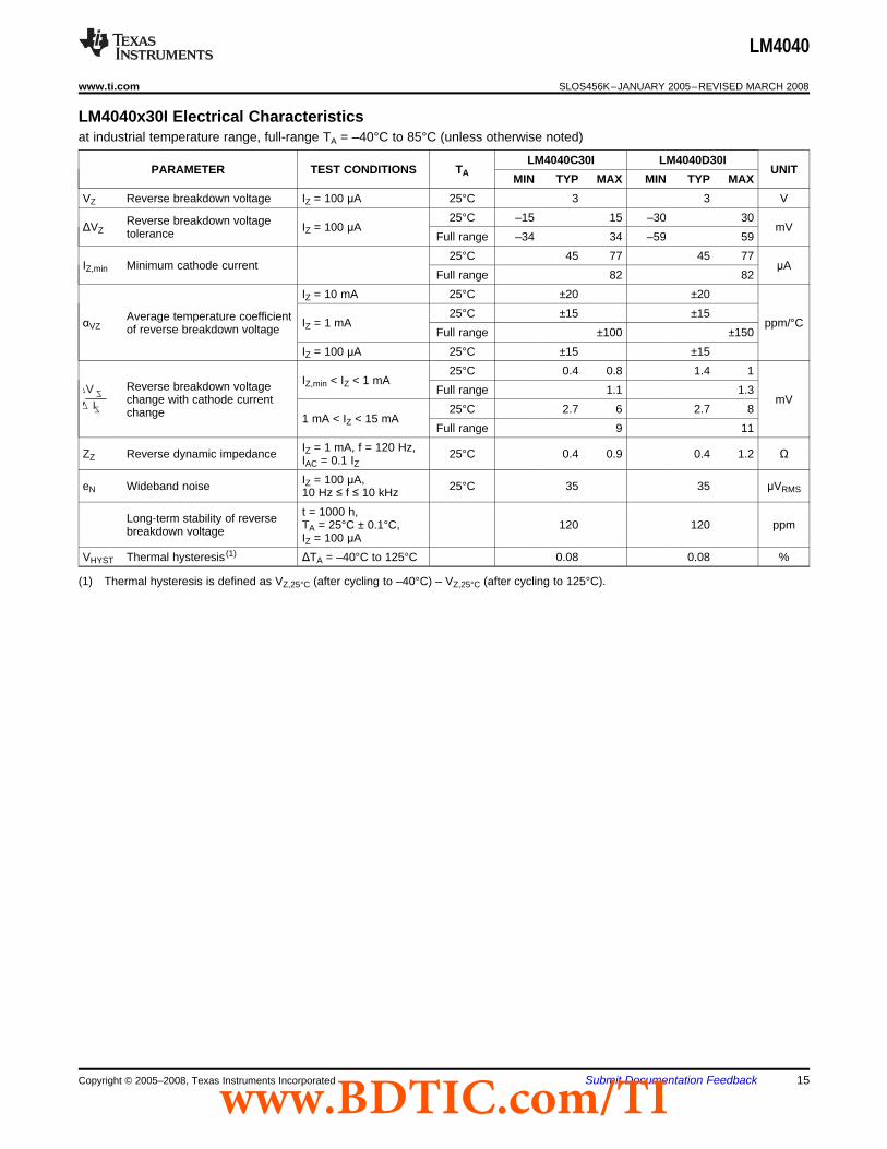
LM4040x30I Electrical Characteristics
VZIZ
LM4040
www.ti.com .................................................................................................................................................. SLOS456K–JANUARY 2005–REVISED MARCH 2008
at industrial temperature range, full-range TA = –40°C to 85°C (unless otherwise noted)
LM4040C30I LM4040D30IPARAMETER TEST CONDITIONS TA UNIT
MIN TYP MAX MIN TYP MAXVZ Reverse breakdown voltage IZ = 100 μA 25°C 3 3 V
25°C –15 15 –30 30Reverse breakdown voltageΔVZ IZ = 100 μA mVtolerance Full range –34 34 –59 5925°C 45 77 45 77
IZ,min Minimum cathode current μAFull range 82 82
IZ = 10 mA 25°C ±20 ±2025°C ±15 ±15Average temperature coefficientαVZ IZ = 1 mA ppm/°Cof reverse breakdown voltage Full range ±100 ±150
IZ = 100 μA 25°C ±15 ±1525°C 0.4 0.8 1.4 1
IZ,min < IZ < 1 mAReverse breakdown voltage Full range 1.1 1.3change with cathode current mV
25°C 2.7 6 2.7 8change 1 mA < IZ < 15 mAFull range 9 11
IZ = 1 mA, f = 120 Hz,ZZ Reverse dynamic impedance 25°C 0.4 0.9 0.4 1.2 ΩIAC = 0.1 IZIZ = 100 μA,eN Wideband noise 25°C 35 35 μVRMS10 Hz ≤ f ≤ 10 kHzt = 1000 h,Long-term stability of reverse TA = 25°C ± 0.1°C, 120 120 ppmbreakdown voltage IZ = 100 μA
VHYST Thermal hysteresis (1) ΔTA = –40°C to 125°C 0.08 0.08 %
(1) Thermal hysteresis is defined as VZ,25°C (after cycling to –40°C) – VZ,25°C (after cycling to 125°C).
Copyright © 2005–2008, Texas Instruments Incorporated Submit Documentation Feedback 15www.BDTIC.com/TI

LM4040x30Q Electrical Characteristics
VZIZ
LM4040
SLOS456K–JANUARY 2005–REVISED MARCH 2008 .................................................................................................................................................. www.ti.com
at extended temperature range, full-range TA = –40°C to 125°C (unless otherwise noted)
LM4040C30Q LM4040D30QPARAMETER TEST CONDITIONS TA UNIT
MIN TYP MAX MIN TYP MAXVZ Reverse breakdown voltage IZ = 100 μA 25°C 3 3 V
25°C –15 15 –30 30Reverse breakdown voltageΔVZ IZ = 100 μA mVtolerance Full range –45 45 –75 7525°C 47 77 47 77
IZ,min Minimum cathode current μAFull range 82 82
IZ = 10 mA 25°C ±20 ±2025°C ±15 ±15Average temperature coefficientαVZ IZ = 1 mA ppm/°Cof reverse breakdown voltage Full range ±100 ±150
IZ = 100 μA 25°C ±15 ±1525°C 0.4 0.8 0.4 1.1
IZ,min < IZ < 1 mAReverse breakdown voltage Full range 1.1 1.3change with cathode current mV
25°C 2.7 6 2.7 8change 1 mA < IZ < 15 mAFull range 9 11
IZ = 1 mA, f = 120 Hz,ZZ Reverse dynamic impedance 25°C 0.4 0.9 0.4 1.2 ΩIAC = 0.1 IZIZ = 100 μA,eN Wideband noise 25°C 35 35 μVRMS10 Hz ≤ f ≤ 10 kHzt = 1000 h,Long-term stability of reverse TA = 25°C ± 0.1°C, 120 120 ppmbreakdown voltage IZ = 100 μA
VHYST Thermal hysteresis (1) ΔTA = –40°C to 125°C 0.08 0.08 %
(1) Thermal hysteresis is defined as VZ,25°C (after cycling to –40°C) – VZ,25°C (after cycling to 125°C).
16 Submit Documentation Feedback Copyright © 2005–2008, Texas Instruments Incorporatedwww.BDTIC.com/TI
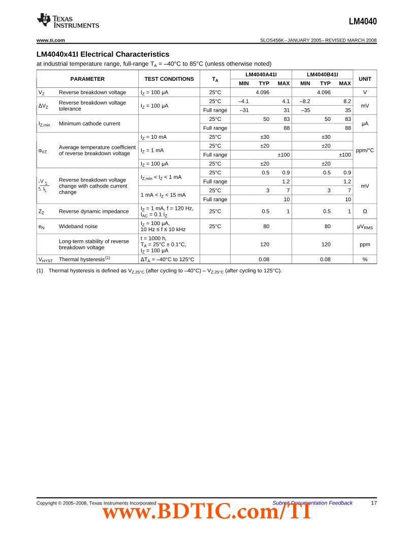
LM4040x41I Electrical Characteristics
VZIZ
LM4040
www.ti.com .................................................................................................................................................. SLOS456K–JANUARY 2005–REVISED MARCH 2008
at industrial temperature range, full-range TA = –40°C to 85°C (unless otherwise noted)
LM4040A41I LM4040B41IPARAMETER TEST CONDITIONS TA UNIT
MIN TYP MAX MIN TYP MAXVZ Reverse breakdown voltage IZ = 100 μA 25°C 4.096 4.096 V
25°C –4.1 4.1 –8.2 8.2Reverse breakdown voltageΔVZ IZ = 100 μA mVtolerance Full range –31 31 –35 3525°C 50 83 50 83
IZ,min Minimum cathode current μAFull range 88 88
IZ = 10 mA 25°C ±30 ±3025°C ±20 ±20Average temperature coefficientαVZ IZ = 1 mA ppm/°Cof reverse breakdown voltage Full range ±100 ±100
IZ = 100 μA 25°C ±20 ±2025°C 0.5 0.9 0.5 0.9
IZ,min < IZ < 1 mAReverse breakdown voltage Full range 1.2 1.2change with cathode current mV
25°C 3 7 3 7change 1 mA < IZ < 15 mAFull range 10 10
IZ = 1 mA, f = 120 Hz,ZZ Reverse dynamic impedance 25°C 0.5 1 0.5 1 ΩIAC = 0.1 IZIZ = 100 μA,eN Wideband noise 25°C 80 80 μVRMS10 Hz ≤ f ≤ 10 kHzt = 1000 h,Long-term stability of reverse TA = 25°C ± 0.1°C, 120 120 ppmbreakdown voltage IZ = 100 μA
VHYST Thermal hysteresis (1) ΔTA = –40°C to 125°C 0.08 0.08 %
(1) Thermal hysteresis is defined as VZ,25°C (after cycling to –40°C) – VZ,25°C (after cycling to 125°C).
Copyright © 2005–2008, Texas Instruments Incorporated Submit Documentation Feedback 17www.BDTIC.com/TI

LM4040x41I Electrical Characteristics
VZIZ
LM4040
SLOS456K–JANUARY 2005–REVISED MARCH 2008 .................................................................................................................................................. www.ti.com
at industrial temperature range, full-range TA = –40°C to 85°C (unless otherwise noted)
LM4040C41I LM4040D41IPARAMETER TEST CONDITIONS TA UNIT
MIN TYP MAX MIN TYP MAXVZ Reverse breakdown voltage IZ = 100 μA 25°C 4.096 4.096 V
25°C –20 20 –41 41Reverse breakdown voltageΔVZ IZ = 100 μA mVtolerance Full range –47 47 –81 8125°C 50 83 50 83
IZ,min Minimum cathode current μAFull range 88 88
IZ = 10 mA 25°C ±30 ±3025°C ±20 ±20Average temperature coefficientαVZ IZ = 1 mA ppm/°Cof reverse breakdown voltage Full range ±100 ±150
IZ = 100 μA 25°C ±20 ±2025°C 0.5 0.9 0.5 1.2
IZ,min < IZ < 1 mAReverse breakdown voltage Full range 1.2 1.5change with cathode current mV
25°C 3 7 3 9change 1 mA < IZ < 15 mAFull range 10 13
IZ = 1 mA, f = 120 Hz,ZZ Reverse dynamic impedance 25°C 0.5 1 0.5 1.3 ΩIAC = 0.1 IZIZ = 100 μA,eN Wideband noise 25°C 80 80 μVRMS10 Hz ≤ f ≤ 10 kHzt = 1000 h,Long-term stability of reverse TA = 25°C ± 0.1°C, 120 120 ppmbreakdown voltage IZ = 100 μA
VHYST Thermal hysteresis (1) ΔTA = –40°C to 125°C 0.08 0.08 %
(1) Thermal hysteresis is defined as VZ,25°C (after cycling to –40°C) – VZ,25°C (after cycling to 125°C).
18 Submit Documentation Feedback Copyright © 2005–2008, Texas Instruments Incorporatedwww.BDTIC.com/TI

LM4040x50I Electrical Characteristics
VZIZ
LM4040
www.ti.com .................................................................................................................................................. SLOS456K–JANUARY 2005–REVISED MARCH 2008
at industrial temperature range, full-range TA = –40°C to 85°C (unless otherwise noted)
LM4040A50I LM4040B50IPARAMETER TEST CONDITIONS TA UNIT
MIN TYP MAX MIN TYP MAXVZ Reverse breakdown voltage IZ = 100 μA 25°C 5 5 V
25°C –5 5 –10 10Reverse breakdown voltageΔVZ IZ = 100 μA mVtolerance Full range –38 38 –43 4325°C 65 89 65 89
IZ,min Minimum cathode current μAFull range 95 95
IZ = 10 mA 25°C ±30 ±3025°C ±20 ±20Average temperature coefficientαVZ IZ = 1 mA ppm/°Cof reverse breakdown voltage Full range ±100 ±100
IZ = 100 μA 25°C ±20 ±2025°C 0.5 1 0.5 1
IZ,min < IZ < 1 mAReverse breakdown voltage Full range 1.4 1.4change with cathode current mV
25°C 3.5 8 3.5 8change 1 mA < IZ < 15 mAFull range 12 12
IZ = 1 mA, f = 120 Hz,ZZ Reverse dynamic impedance 25°C 0.5 1.1 0.5 1.1 ΩIAC = 0.1 IZIZ = 100 μA,eN Wideband noise 25°C 80 80 μVRMS10 Hz ≤ f ≤ 10 kHzt = 1000 h,Long-term stability of reverse TA = 25°C ± 0.1°C, 120 120 ppmbreakdown voltage IZ = 100 μA
VHYST Thermal hysteresis (1) ΔTA = –40°C to 125°C 0.08 0.08 %
(1) Thermal hysteresis is defined as VZ,25°C (after cycling to –40°C) – VZ,25°C (after cycling to 125°C).
Copyright © 2005–2008, Texas Instruments Incorporated Submit Documentation Feedback 19www.BDTIC.com/TI

LM4040x50I Electrical Characteristics
VZIZ
LM4040
SLOS456K–JANUARY 2005–REVISED MARCH 2008 .................................................................................................................................................. www.ti.com
at industrial temperature range, full-range TA = –40°C to 85°C (unless otherwise noted)
LM4040C50I LM4040D50IPARAMETER TEST CONDITIONS TA UNIT
MIN TYP MAX MIN TYP MAXVZ Reverse breakdown voltage IZ = 100 μA 25°C 5 5 V
25°C –25 25 –50 50Reverse breakdown voltageΔVZ IZ = 100 μA mVtolerance Full range –58 58 –99 9925°C 65 89 65 89
IZ,min Minimum cathode current μAFull range 95 95
IZ = 10 mA 25°C ±30 ±3025°C ±20 ±20Average temperature coefficientαVZ IZ = 1 mA ppm/°Cof reverse breakdown voltage Full range ±100 ±150
IZ = 100 μA 25°C ±20 ±2025°C 0.5 1 0.5 1.3
IZ,min < IZ < 1 mAReverse breakdown voltage Full range 1.4 1.8change with cathode current mV
25°C 3.5 8 3.5 10change 1 mA < IZ < 15 mAFull range 12 15
IZ = 1 mA, f = 120 Hz,ZZ Reverse dynamic impedance 25°C 0.5 1.1 0.5 1.5 ΩIAC = 0.1 IZIZ = 100 μA,eN Wideband noise 25°C 80 80 μVRMS10 Hz ≤ f ≤ 10 kHzt = 1000 h,Long-term stability of reverse TA = 25°C ± 0.1°C, 120 120 ppmbreakdown voltage IZ = 100 μA
VHYST Thermal hysteresis (1) ΔTA = –40°C to 125°C 0.08 0.08 %
(1) Thermal hysteresis is defined as VZ,25°C (after cycling to –40°C) – VZ,25°C (after cycling to 125°C).
20 Submit Documentation Feedback Copyright © 2005–2008, Texas Instruments Incorporatedwww.BDTIC.com/TI

LM4040x50Q Electrical Characteristics
VZIZ
LM4040
www.ti.com .................................................................................................................................................. SLOS456K–JANUARY 2005–REVISED MARCH 2008
at extended temperature range, full-range TA = –40°C to 125°C (unless otherwise noted)
LM4040C50Q LM4040D50QPARAMETER TEST CONDITIONS TA UNIT
MIN TYP MAX MIN TYP MAXVZ Reverse breakdown voltage IZ = 100 μA 25°C 5 5 V
25°C –25 25 –50 50Reverse breakdown voltageΔVZ IZ = 100 μA mVtolerance Full range –75 75 –125 12525°C 65 89 65 89
IZ,min Minimum cathode current μAFull range 95 95
IZ = 10 mA 25°C ±30 ±3025°C ±20 ±20Average temperature coefficientαVZ IZ = 1 mA ppm/°Cof reverse breakdown voltage Full range ±100 ±150
IZ = 100 μA 25°C ±20 ±2025°C 0.5 1 0.5 1
IZ,min < IZ < 1 mAReverse breakdown voltage Full range 1.4 1.8change with cathode current mV
25°C 3.5 8 3.5 8change 1 mA < IZ < 15 mAFull range 12 12
IZ = 1 mA, f = 120 Hz,ZZ Reverse dynamic impedance 25°C 0.5 1.1 0.5 1.1 ΩIAC = 0.1 IZIZ = 100 μA,eN Wideband noise 25°C 80 80 μVRMS10 Hz ≤ f ≤ 10 kHzt = 1000 h,Long-term stability of reverse TA = 25°C ± 0.1°C, 120 120 ppmbreakdown voltage IZ = 100 μA
VHYST Thermal hysteresis (1) ΔTA = –40°C to 125°C 0.08 0.08 %
(1) Thermal hysteresis is defined as VZ,25°C (after cycling to –40°C) – VZ,25°C (after cycling to 125°C).
Copyright © 2005–2008, Texas Instruments Incorporated Submit Documentation Feedback 21www.BDTIC.com/TI
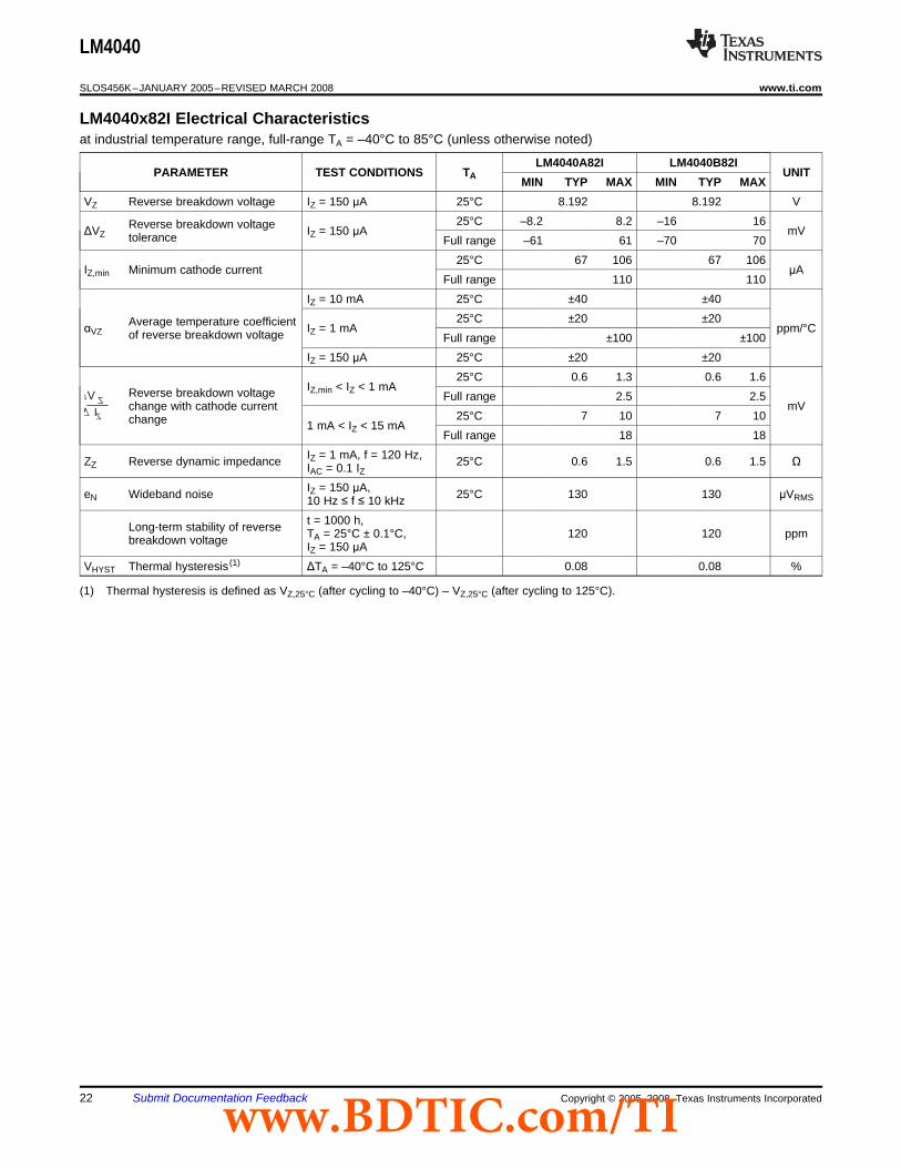
LM4040x82I Electrical Characteristics
VZIZ
LM4040
SLOS456K–JANUARY 2005–REVISED MARCH 2008 .................................................................................................................................................. www.ti.com
at industrial temperature range, full-range TA = –40°C to 85°C (unless otherwise noted)
LM4040A82I LM4040B82IPARAMETER TEST CONDITIONS TA UNIT
MIN TYP MAX MIN TYP MAXVZ Reverse breakdown voltage IZ = 150 μA 25°C 8.192 8.192 V
25°C –8.2 8.2 –16 16Reverse breakdown voltageΔVZ IZ = 150 μA mVtolerance Full range –61 61 –70 7025°C 67 106 67 106
IZ,min Minimum cathode current μAFull range 110 110
IZ = 10 mA 25°C ±40 ±4025°C ±20 ±20Average temperature coefficientαVZ IZ = 1 mA ppm/°Cof reverse breakdown voltage Full range ±100 ±100
IZ = 150 μA 25°C ±20 ±2025°C 0.6 1.3 0.6 1.6
IZ,min < IZ < 1 mAReverse breakdown voltage Full range 2.5 2.5change with cathode current mV
25°C 7 10 7 10change 1 mA < IZ < 15 mAFull range 18 18
IZ = 1 mA, f = 120 Hz,ZZ Reverse dynamic impedance 25°C 0.6 1.5 0.6 1.5 ΩIAC = 0.1 IZIZ = 150 μA,eN Wideband noise 25°C 130 130 μVRMS10 Hz ≤ f ≤ 10 kHzt = 1000 h,Long-term stability of reverse TA = 25°C ± 0.1°C, 120 120 ppmbreakdown voltage IZ = 150 μA
VHYST Thermal hysteresis (1) ΔTA = –40°C to 125°C 0.08 0.08 %
(1) Thermal hysteresis is defined as VZ,25°C (after cycling to –40°C) – VZ,25°C (after cycling to 125°C).
22 Submit Documentation Feedback Copyright © 2005–2008, Texas Instruments Incorporatedwww.BDTIC.com/TI

LM4040x82I Electrical Characteristics
VZIZ
LM4040
www.ti.com .................................................................................................................................................. SLOS456K–JANUARY 2005–REVISED MARCH 2008
at industrial temperature range, full-range TA = –40°C to 85°C (unless otherwise noted)
LM4040C82I LM4040D82IPARAMETER TEST CONDITIONS TA UNIT
MIN TYP MAX MIN TYP MAXVZ Reverse breakdown voltage IZ = 150 μA 25°C 8.192 8.192 V
25°C –41 41 –82 82Reverse breakdown voltageΔVZ IZ = 150 μA mVtolerance Full range –94 94 –162 16225°C 67 106 67 111
IZ,min Minimum cathode current μAFull range 110 115
IZ = 10 mA 25°C ±40 ±4025°C ±20 ±20Average temperature coefficientαVZ IZ = 1 mA ppm/°Cof reverse breakdown voltage Full range ±100 ±150
IZ = 150 μA 25°C ±20 ±2025°C 0.6 1.3 0.6 1.7
IZ,min < IZ < 1 mAReverse breakdown voltage Full range 2.5 3change with cathode current mV
25°C 7 10 7 15change 1 mA < IZ < 15 mAFull range 18 24
IZ = 1 mA, f = 120 Hz,ZZ Reverse dynamic impedance 25°C 0.6 1.5 0.6 1.9 ΩIAC = 0.1 IZIZ = 150 μA,eN Wideband noise 25°C 130 130 μVRMS10 Hz ≤ f ≤ 10 kHzt = 1000 h,Long-term stability of reverse TA = 25°C ± 0.1°C, 120 120 ppmbreakdown voltage IZ = 150 μA
VHYST Thermal hysteresis (1) ΔTA = –40°C to 125°C 0.08 0.08 %
(1) Thermal hysteresis is defined as VZ,25°C (after cycling to –40°C) – VZ,25°C (after cycling to 125°C).
Copyright © 2005–2008, Texas Instruments Incorporated Submit Documentation Feedback 23www.BDTIC.com/TI

LM4040x10I Electrical Characteristics
VZIZ
LM4040
SLOS456K–JANUARY 2005–REVISED MARCH 2008 .................................................................................................................................................. www.ti.com
at industrial temperature range, full-range TA = –40°C to 85°C (unless otherwise noted)
LM4040A10I LM4040B10IPARAMETER TEST CONDITIONS TA UNIT
MIN TYP MAX MIN TYP MAXVZ Reverse breakdown voltage IZ = 150 μA 25°C 10 10 V
25°C –10 10 –20 20Reverse breakdown voltageΔVZ IZ = 150 μA mVtolerance Full range –75 75 –85 8525°C 75 120 75 120
IZ,min Minimum cathode current μAFull range 125 125
IZ = 10 mA 25°C ±40 ±4025°C ±20 ±20Average temperature coefficientαVZ IZ = 1 mA ppm/°Cof reverse breakdown voltage Full range ±100 ±100
IZ = 150 μA 25°C ±20 ±2025°C 0.8 1.5 0.8 1.5
IZ,min < IZ < 1 mAReverse breakdown voltage Full range 3.5 3.5change with cathode current mV
25°C 8 14 8 14change 1 mA < IZ < 15 mAFull range 24 24
IZ = 1 mA, f = 120 Hz,ZZ Reverse dynamic impedance 25°C 0.7 1.7 0.7 1.7 ΩIAC = 0.1 IZIZ = 150 μA,eN Wideband noise 25°C 180 180 μVRMS10 Hz ≤ f ≤ 10 kHzt = 1000 h,Long-term stability of reverse TA = 25°C ± 0.1°C, 120 120 ppmbreakdown voltage IZ = 150 μA
VHYST Thermal hysteresis (1) ΔTA = –40°C to 125°C 0.08 0.08 %
(1) Thermal hysteresis is defined as VZ,25°C (after cycling to –40°C) – VZ,25°C (after cycling to 125°C).
24 Submit Documentation Feedback Copyright © 2005–2008, Texas Instruments Incorporatedwww.BDTIC.com/TI

LM4040x10I Electrical Characteristics
VZIZ
LM4040
www.ti.com .................................................................................................................................................. SLOS456K–JANUARY 2005–REVISED MARCH 2008
at industrial temperature range, full-range TA = –40°C to 85°C (unless otherwise noted)
LM4040C10I LM4040D10IPARAMETER TEST CONDITIONS TA UNIT
MIN TYP MAX MIN TYP MAXVZ Reverse breakdown voltage IZ = 150 μA 25°C 10 10 V
25°C –50 50 –100 100Reverse breakdown voltageΔVZ IZ = 150 μA mVtolerance Full range –115 115 –198 19825°C 75 120 75 130
IZ,min Minimum cathode current μAFull range 125 135
IZ = 10 mA 25°C ±40 ±4025°C ±20 ±20Average temperature coefficientαVZ IZ = 1 mA ppm/°Cof reverse breakdown voltage Full range ±100 ±150
IZ = 150 μA 25°C ±20 ±2025°C 0.8 1.5 0.8 2
IZ,min < IZ < 1 mAReverse breakdown voltage Full range 3.5 4change with cathode current mV
25°C 8 14 8 18change 1 mA < IZ < 15 mAFull range 24 29
IZ = 1 mA, f = 120 Hz,ZZ Reverse dynamic impedance 25°C 0.7 1.7 0.7 2.3 ΩIAC = 0.1 IZIZ = 150 μA,eN Wideband noise 25°C 180 180 μVRMS10 Hz ≤ f ≤ 10 kHzt = 1000 h,Long-term stability of reverse TA = 25°C ± 0.1°C, 120 120 ppmbreakdown voltage IZ = 150 μA
VHYST Thermal hysteresis (1) ΔTA = –40°C to 125°C 0.08 0.08 %
(1) Thermal hysteresis is defined as VZ,25°C (after cycling to –40°C) – VZ,25°C (after cycling to 125°C).
Copyright © 2005–2008, Texas Instruments Incorporated Submit Documentation Feedback 25www.BDTIC.com/TI
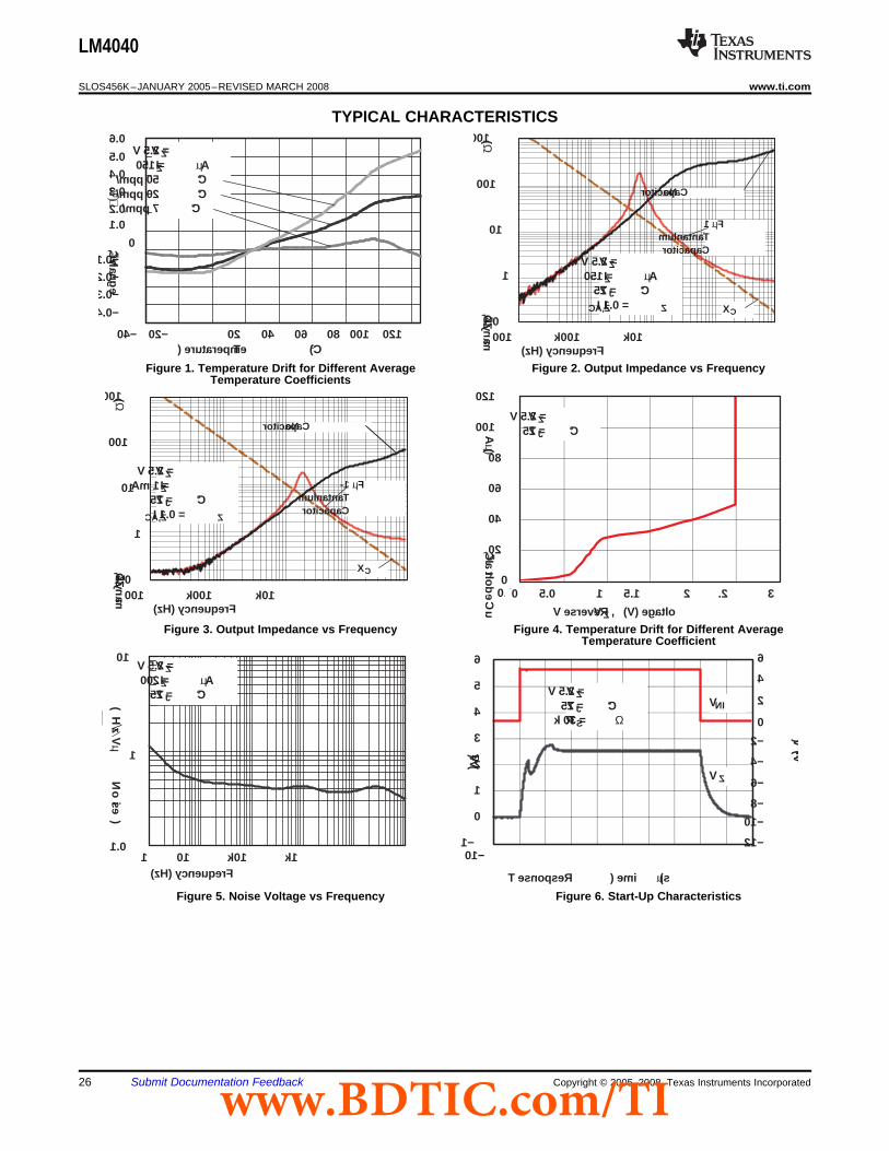
TYPICAL CHARACTERISTICS
Temperature ( C)
VZ, Change
%)
VZ = 2.5 VIZ = 150 µA50 ppm/ °C20 ppm/ °C7 ppm/ °C
−0.4
0.1
0−0.1
−0.2
−0.3
0.6
0.5
0.4
0.3
0.2
−400 −20 12010080604020 1001k1M 10k100kFrequency (Hz)
ZZ, Dynamic Output Impedance (
Ω) 1000
100
10
1
0.1
VZ = 2.5 VIZ = 150 µATJ = 25 °CIZ,AC = 0.1 I Z XC
No Capacitor
1 µFTantanlumCapacitor
1001k1M 10k100kFrequency (Hz)
ZZ, Dynamic Output Impedance (
Ω) 1000
100
10
1
0.1
VZ = 2.5 VIZ = 1 mATJ = 25 °CIZ,AC = 0.1 I Z
XC
No Capacitor
1- µFTantanlumCapacitor
0
20
40
60
80
100
120
0.00.51.01.52.02.53.0
VZ, Reverse V oltage (V)
I Z, Cathode Current
µA)
VZ = 2.5 VTJ = 25 °C
0 1 2.51.5 20.5 3
1100100k 1k10kFrequency (Hz)
Noise (
µVHz
)
10
1
0.110
VZ = 2.5 VIZ = 200 µATJ = 25 °C
−1
0
1
2
3
4
5
6
−100102030405060708090
VZ (V)
VZ = 2.5 VTJ = 25 °CRS = 30 k Ω
Response T ime ( µs)
VIN
VZ
VIN (V)
6
4
2
0
−2
−4
−6
−8
−10
−12
LM4040
SLOS456K–JANUARY 2005–REVISED MARCH 2008 .................................................................................................................................................. www.ti.com
Figure 1. Temperature Drift for Different Average Figure 2. Output Impedance vs FrequencyTemperature Coefficients
Figure 3. Output Impedance vs Frequency Figure 4. Temperature Drift for Different AverageTemperature Coefficient
Figure 5. Noise Voltage vs Frequency Figure 6. Start-Up Characteristics
26 Submit Documentation Feedback Copyright © 2005–2008, Texas Instruments Incorporatedwww.BDTIC.com/TI

APPLICATION INFORMATION
Start-Up Characteristics
1-Hz Rate
VZLM4040
RS
VIN
Output Capacitor
SOT-23 Connections
Use With ADCs or DACs
28
27
26
25
24
23
22
21
20
19
18
17
16
1514
13
12
11
10
9
8
1
2
3
4
5
6
7
VREF
AIN0
AIN1
AIN2
AGND
DB11
DB10
DB9
DB8
DB7
DB6
DB5
DGND
AIN3
VANA
2.2 µF
A1
A0
CLK
DB0
DB1
DB2
DB3
DB4
VDIG
BUSY
WR
CS
RD
3.2-MHz Clock
BUSY Output
Write Input
Read Input
5-V Analog Supply10 µF
+
++0.1 µF
ADS7842
LM4040A-41
909
0 V to V REF
5 V
LM4040
www.ti.com .................................................................................................................................................. SLOS456K–JANUARY 2005–REVISED MARCH 2008
Figure 7. Test Circuit
The LM4040 does not require an output capacitor across cathode and anode for stability. However, if an outputbypass capacitor is desired, the LM4040 is designed to be stable with all capacitive loads.
There is a parasitic Schottky diode connected between pins 2 and 3 of the SOT-23 packaged device. Thus, pin 3of the SOT-23 package must be left floating or connected to pin 2.
The LM4040x-41 is designed to be a cost-effective voltage reference as required in 12-bit data-acquisitionsystems. For 12-bit systems operating from 5-V supplies such as the ADS7842 (see Figure 8), the LM4040x-41(4.096 V) permits operation with an LSB of 1 mV.
Figure 8. Data-Acquisition Circuit With LM4040x-41
Copyright © 2005–2008, Texas Instruments Incorporated Submit Documentation Feedback 27www.BDTIC.com/TI
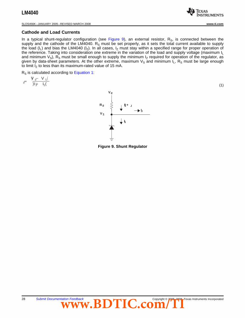
Cathode and Load Currents
RS VS VZ
(IL IZ) (1)
LM4040
IZ + I L
IL
IZ
VS
VZ
RS
LM4040
SLOS456K–JANUARY 2005–REVISED MARCH 2008 .................................................................................................................................................. www.ti.com
In a typical shunt-regulator configuration (see Figure 9), an external resistor, RS, is connected between thesupply and the cathode of the LM4040. RS must be set properly, as it sets the total current available to supplythe load (IL) and bias the LM4040 (IZ). In all cases, IZ must stay within a specified range for proper operation ofthe reference. Taking into consideration one extreme in the variation of the load and supply voltage (maximum ILand minimum VS), RS must be small enough to supply the minimum IZ required for operation of the regulator, asgiven by data-sheet parameters. At the other extreme, maximum VS and minimum IL, RS must be large enoughto limit IZ to less than its maximum-rated value of 15 mA.
RS is calculated according to Equation 1:
Figure 9. Shunt Regulator
28 Submit Documentation Feedback Copyright © 2005–2008, Texas Instruments Incorporatedwww.BDTIC.com/TI
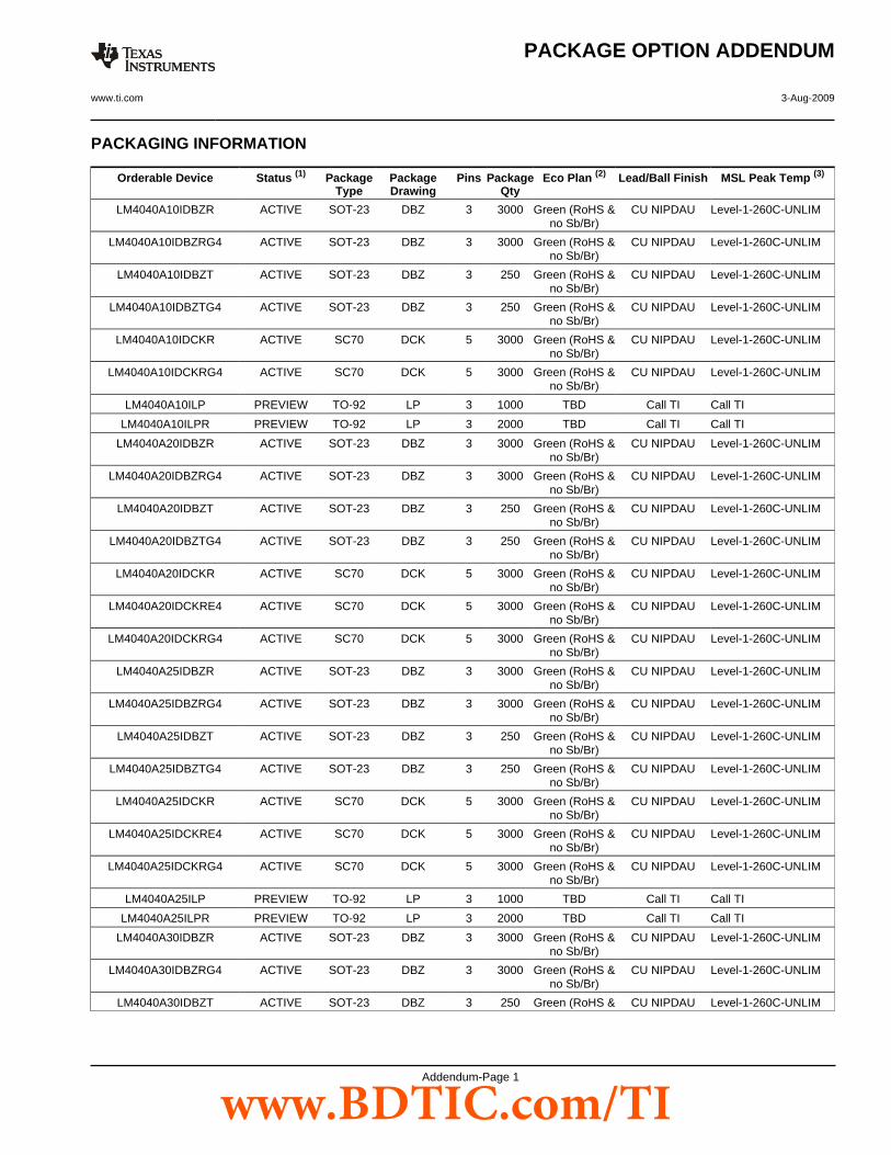
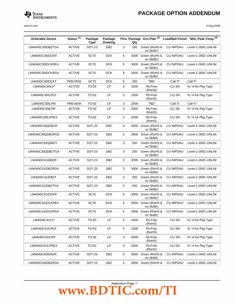
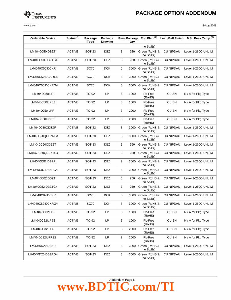
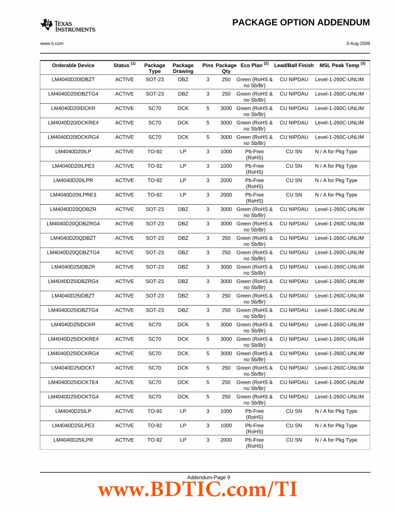
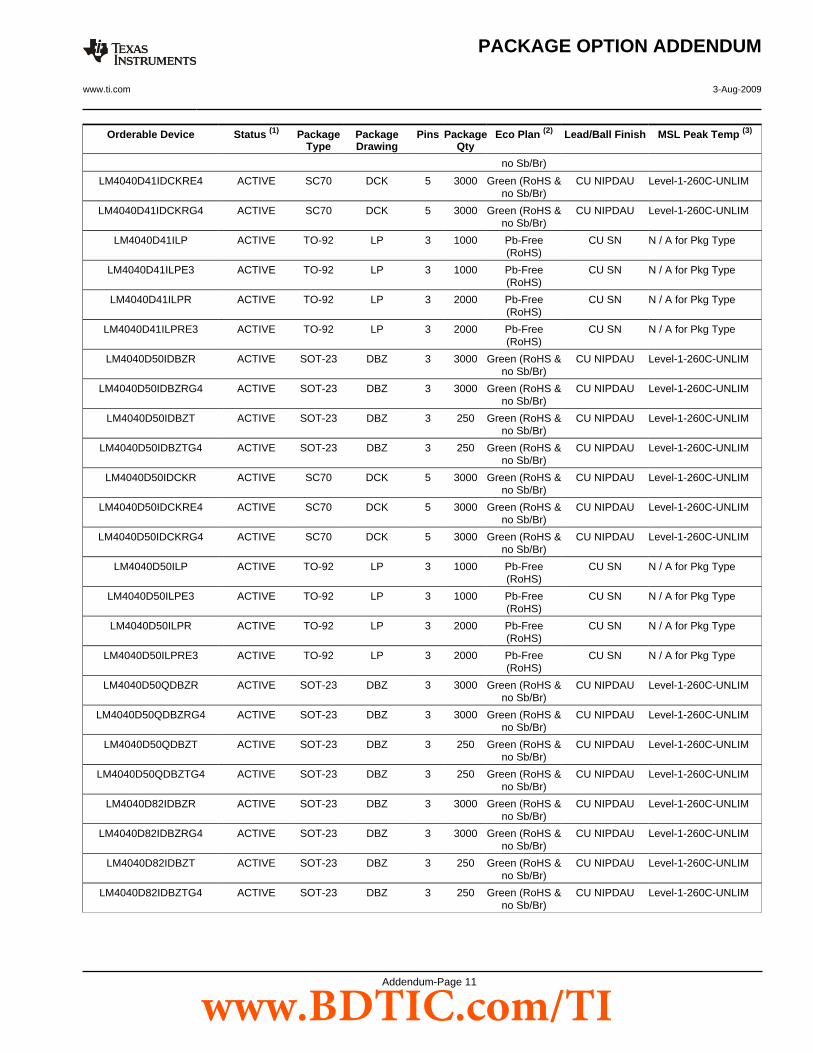
PACKAGING INFORMATION
Orderable Device Status (1) PackageType
PackageDrawing
Pins PackageQty
Eco Plan (2) Lead/Ball Finish MSL Peak Temp (3)
LM4040A10IDBZR ACTIVE SOT-23 DBZ 3 3000 Green (RoHS &no Sb/Br)
CU NIPDAU Level-1-260C-UNLIM
LM4040A10IDBZRG4 ACTIVE SOT-23 DBZ 3 3000 Green (RoHS &no Sb/Br)
CU NIPDAU Level-1-260C-UNLIM
LM4040A10IDBZT ACTIVE SOT-23 DBZ 3 250 Green (RoHS &no Sb/Br)
CU NIPDAU Level-1-260C-UNLIM
LM4040A10IDBZTG4 ACTIVE SOT-23 DBZ 3 250 Green (RoHS &no Sb/Br)
CU NIPDAU Level-1-260C-UNLIM
LM4040A10IDCKR ACTIVE SC70 DCK 5 3000 Green (RoHS &no Sb/Br)
CU NIPDAU Level-1-260C-UNLIM
LM4040A10IDCKRG4 ACTIVE SC70 DCK 5 3000 Green (RoHS &no Sb/Br)
CU NIPDAU Level-1-260C-UNLIM
LM4040A10ILP PREVIEW TO-92 LP 3 1000 TBD Call TI Call TI
LM4040A10ILPR PREVIEW TO-92 LP 3 2000 TBD Call TI Call TI
LM4040A20IDBZR ACTIVE SOT-23 DBZ 3 3000 Green (RoHS &no Sb/Br)
CU NIPDAU Level-1-260C-UNLIM
LM4040A20IDBZRG4 ACTIVE SOT-23 DBZ 3 3000 Green (RoHS &no Sb/Br)
CU NIPDAU Level-1-260C-UNLIM
LM4040A20IDBZT ACTIVE SOT-23 DBZ 3 250 Green (RoHS &no Sb/Br)
CU NIPDAU Level-1-260C-UNLIM
LM4040A20IDBZTG4 ACTIVE SOT-23 DBZ 3 250 Green (RoHS &no Sb/Br)
CU NIPDAU Level-1-260C-UNLIM
LM4040A20IDCKR ACTIVE SC70 DCK 5 3000 Green (RoHS &no Sb/Br)
CU NIPDAU Level-1-260C-UNLIM
LM4040A20IDCKRE4 ACTIVE SC70 DCK 5 3000 Green (RoHS &no Sb/Br)
CU NIPDAU Level-1-260C-UNLIM
LM4040A20IDCKRG4 ACTIVE SC70 DCK 5 3000 Green (RoHS &no Sb/Br)
CU NIPDAU Level-1-260C-UNLIM
LM4040A25IDBZR ACTIVE SOT-23 DBZ 3 3000 Green (RoHS &no Sb/Br)
CU NIPDAU Level-1-260C-UNLIM
LM4040A25IDBZRG4 ACTIVE SOT-23 DBZ 3 3000 Green (RoHS &no Sb/Br)
CU NIPDAU Level-1-260C-UNLIM
LM4040A25IDBZT ACTIVE SOT-23 DBZ 3 250 Green (RoHS &no Sb/Br)
CU NIPDAU Level-1-260C-UNLIM
LM4040A25IDBZTG4 ACTIVE SOT-23 DBZ 3 250 Green (RoHS &no Sb/Br)
CU NIPDAU Level-1-260C-UNLIM
LM4040A25IDCKR ACTIVE SC70 DCK 5 3000 Green (RoHS &no Sb/Br)
CU NIPDAU Level-1-260C-UNLIM
LM4040A25IDCKRE4 ACTIVE SC70 DCK 5 3000 Green (RoHS &no Sb/Br)
CU NIPDAU Level-1-260C-UNLIM
LM4040A25IDCKRG4 ACTIVE SC70 DCK 5 3000 Green (RoHS &no Sb/Br)
CU NIPDAU Level-1-260C-UNLIM
LM4040A25ILP PREVIEW TO-92 LP 3 1000 TBD Call TI Call TI
LM4040A25ILPR PREVIEW TO-92 LP 3 2000 TBD Call TI Call TI
LM4040A30IDBZR ACTIVE SOT-23 DBZ 3 3000 Green (RoHS &no Sb/Br)
CU NIPDAU Level-1-260C-UNLIM
LM4040A30IDBZRG4 ACTIVE SOT-23 DBZ 3 3000 Green (RoHS &no Sb/Br)
CU NIPDAU Level-1-260C-UNLIM
LM4040A30IDBZT ACTIVE SOT-23 DBZ 3 250 Green (RoHS & CU NIPDAU Level-1-260C-UNLIM
PACKAGE OPTION ADDENDUM
www.ti.com 3-Aug-2009
Addendum-Page 1
www.BDTIC.com/TI

Orderable Device Status (1) PackageType
PackageDrawing
Pins PackageQty
Eco Plan (2) Lead/Ball Finish MSL Peak Temp (3)
no Sb/Br)
LM4040A30IDBZTG4 ACTIVE SOT-23 DBZ 3 250 Green (RoHS &no Sb/Br)
CU NIPDAU Level-1-260C-UNLIM
LM4040A30IDCKR ACTIVE SC70 DCK 5 3000 Green (RoHS &no Sb/Br)
CU NIPDAU Level-1-260C-UNLIM
LM4040A30IDCKRE4 ACTIVE SC70 DCK 5 3000 Green (RoHS &no Sb/Br)
CU NIPDAU Level-1-260C-UNLIM
LM4040A30IDCKRG4 ACTIVE SC70 DCK 5 3000 Green (RoHS &no Sb/Br)
CU NIPDAU Level-1-260C-UNLIM
LM4040A30IDCKT PREVIEW SC70 DCK 5 250 TBD Call TI Call TI
LM4040A30ILP PREVIEW TO-92 LP 3 1000 TBD Call TI Call TI
LM4040A30ILPM PREVIEW TO-92 LP 3 2000 TBD Call TI Call TI
LM4040A30ILPR PREVIEW TO-92 LP 3 2000 TBD Call TI Call TI
LM4040A41IDBZR ACTIVE SOT-23 DBZ 3 3000 Green (RoHS &no Sb/Br)
CU NIPDAU Level-1-260C-UNLIM
LM4040A41IDBZRG4 ACTIVE SOT-23 DBZ 3 3000 Green (RoHS &no Sb/Br)
CU NIPDAU Level-1-260C-UNLIM
LM4040A41IDBZT ACTIVE SOT-23 DBZ 3 250 Green (RoHS &no Sb/Br)
CU NIPDAU Level-1-260C-UNLIM
LM4040A41IDBZTG4 ACTIVE SOT-23 DBZ 3 250 Green (RoHS &no Sb/Br)
CU NIPDAU Level-1-260C-UNLIM
LM4040A41IDCKR ACTIVE SC70 DCK 5 3000 Green (RoHS &no Sb/Br)
CU NIPDAU Level-1-260C-UNLIM
LM4040A41IDCKRE4 ACTIVE SC70 DCK 5 3000 Green (RoHS &no Sb/Br)
CU NIPDAU Level-1-260C-UNLIM
LM4040A41IDCKRG4 ACTIVE SC70 DCK 5 3000 Green (RoHS &no Sb/Br)
CU NIPDAU Level-1-260C-UNLIM
LM4040A41ILP PREVIEW TO-92 LP 3 1000 TBD Call TI Call TI
LM4040A41ILPR PREVIEW TO-92 LP 3 2000 TBD Call TI Call TI
LM4040A50IDBZR ACTIVE SOT-23 DBZ 3 3000 Green (RoHS &no Sb/Br)
CU NIPDAU Level-1-260C-UNLIM
LM4040A50IDBZRG4 ACTIVE SOT-23 DBZ 3 3000 Green (RoHS &no Sb/Br)
CU NIPDAU Level-1-260C-UNLIM
LM4040A50IDBZT ACTIVE SOT-23 DBZ 3 250 Green (RoHS &no Sb/Br)
CU NIPDAU Level-1-260C-UNLIM
LM4040A50IDBZTG4 ACTIVE SOT-23 DBZ 3 250 Green (RoHS &no Sb/Br)
CU NIPDAU Level-1-260C-UNLIM
LM4040A50IDCKR ACTIVE SC70 DCK 5 3000 Green (RoHS &no Sb/Br)
CU NIPDAU Level-1-260C-UNLIM
LM4040A50IDCKRE4 ACTIVE SC70 DCK 5 3000 Green (RoHS &no Sb/Br)
CU NIPDAU Level-1-260C-UNLIM
LM4040A50IDCKRG4 ACTIVE SC70 DCK 5 3000 Green (RoHS &no Sb/Br)
CU NIPDAU Level-1-260C-UNLIM
LM4040A50ILP PREVIEW TO-92 LP 3 1000 TBD Call TI Call TI
LM4040A82IDBZR ACTIVE SOT-23 DBZ 3 3000 Green (RoHS &no Sb/Br)
CU NIPDAU Level-1-260C-UNLIM
LM4040A82IDBZRG4 ACTIVE SOT-23 DBZ 3 3000 Green (RoHS &no Sb/Br)
CU NIPDAU Level-1-260C-UNLIM
LM4040A82IDBZT ACTIVE SOT-23 DBZ 3 250 Green (RoHS &no Sb/Br)
CU NIPDAU Level-1-260C-UNLIM
PACKAGE OPTION ADDENDUM
www.ti.com 3-Aug-2009
Addendum-Page 2
www.BDTIC.com/TI
Orderable Device Status (1) PackageType
PackageDrawing
Pins PackageQty
Eco Plan (2) Lead/Ball Finish MSL Peak Temp (3)
LM4040A82IDBZTG4 ACTIVE SOT-23 DBZ 3 250 Green (RoHS &no Sb/Br)
CU NIPDAU Level-1-260C-UNLIM
LM4040A82IDCKR ACTIVE SC70 DCK 5 3000 Green (RoHS &no Sb/Br)
CU NIPDAU Level-1-260C-UNLIM
LM4040A82IDCKRG4 ACTIVE SC70 DCK 5 3000 Green (RoHS &no Sb/Br)
CU NIPDAU Level-1-260C-UNLIM
LM4040B10IDBZR ACTIVE SOT-23 DBZ 3 3000 Green (RoHS &no Sb/Br)
CU NIPDAU Level-1-260C-UNLIM
LM4040B10IDBZRG4 ACTIVE SOT-23 DBZ 3 3000 Green (RoHS &no Sb/Br)
CU NIPDAU Level-1-260C-UNLIM
LM4040B10IDBZT ACTIVE SOT-23 DBZ 3 250 Green (RoHS &no Sb/Br)
CU NIPDAU Level-1-260C-UNLIM
LM4040B10IDBZTG4 ACTIVE SOT-23 DBZ 3 250 Green (RoHS &no Sb/Br)
CU NIPDAU Level-1-260C-UNLIM
LM4040B10IDCKR ACTIVE SC70 DCK 5 3000 Green (RoHS &no Sb/Br)
CU NIPDAU Level-1-260C-UNLIM
LM4040B10IDCKRG4 ACTIVE SC70 DCK 5 3000 Green (RoHS &no Sb/Br)
CU NIPDAU Level-1-260C-UNLIM
LM4040B10ILP PREVIEW TO-92 LP 3 1000 TBD Call TI Call TI
LM4040B10ILPR PREVIEW TO-92 LP 3 2000 TBD Call TI Call TI
LM4040B20IDBZR ACTIVE SOT-23 DBZ 3 3000 Green (RoHS &no Sb/Br)
CU NIPDAU Level-1-260C-UNLIM
LM4040B20IDBZRG4 ACTIVE SOT-23 DBZ 3 3000 Green (RoHS &no Sb/Br)
CU NIPDAU Level-1-260C-UNLIM
LM4040B20IDBZT ACTIVE SOT-23 DBZ 3 250 Green (RoHS &no Sb/Br)
CU NIPDAU Level-1-260C-UNLIM
LM4040B20IDBZTG4 ACTIVE SOT-23 DBZ 3 250 Green (RoHS &no Sb/Br)
CU NIPDAU Level-1-260C-UNLIM
LM4040B20IDCKR ACTIVE SC70 DCK 5 3000 Green (RoHS &no Sb/Br)
CU NIPDAU Level-1-260C-UNLIM
LM4040B20IDCKRE4 ACTIVE SC70 DCK 5 3000 Green (RoHS &no Sb/Br)
CU NIPDAU Level-1-260C-UNLIM
LM4040B20IDCKRG4 ACTIVE SC70 DCK 5 3000 Green (RoHS &no Sb/Br)
CU NIPDAU Level-1-260C-UNLIM
LM4040B25IDBZR ACTIVE SOT-23 DBZ 3 3000 Green (RoHS &no Sb/Br)
CU NIPDAU Level-1-260C-UNLIM
LM4040B25IDBZRG4 ACTIVE SOT-23 DBZ 3 3000 Green (RoHS &no Sb/Br)
CU NIPDAU Level-1-260C-UNLIM
LM4040B25IDBZT ACTIVE SOT-23 DBZ 3 250 Green (RoHS &no Sb/Br)
CU NIPDAU Level-1-260C-UNLIM
LM4040B25IDBZTG4 ACTIVE SOT-23 DBZ 3 250 Green (RoHS &no Sb/Br)
CU NIPDAU Level-1-260C-UNLIM
LM4040B25IDCKR ACTIVE SC70 DCK 5 3000 Green (RoHS &no Sb/Br)
CU NIPDAU Level-1-260C-UNLIM
LM4040B25IDCKRE4 ACTIVE SC70 DCK 5 3000 Green (RoHS &no Sb/Br)
CU NIPDAU Level-1-260C-UNLIM
LM4040B25IDCKRG4 ACTIVE SC70 DCK 5 3000 Green (RoHS &no Sb/Br)
CU NIPDAU Level-1-260C-UNLIM
LM4040B25ILP PREVIEW TO-92 LP 3 1000 TBD Call TI Call TI
LM4040B25ILPR PREVIEW TO-92 LP 3 2000 TBD Call TI Call TI
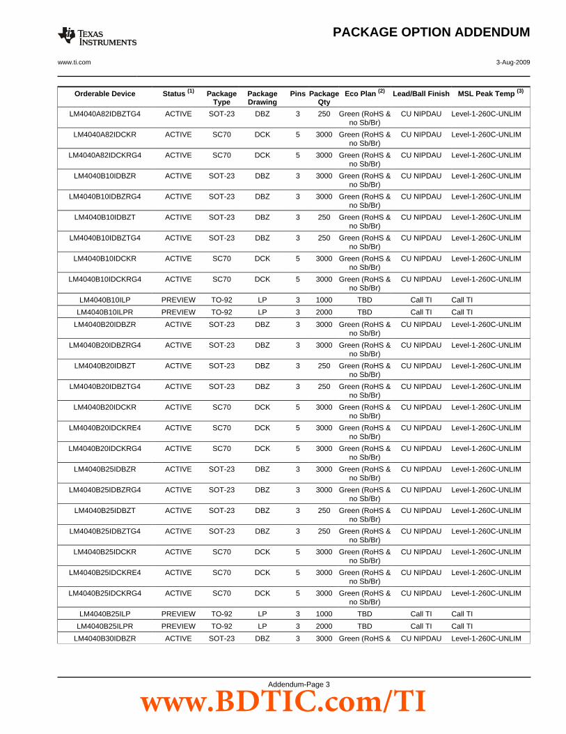
LM4040B30IDBZR ACTIVE SOT-23 DBZ 3 3000 Green (RoHS & CU NIPDAU Level-1-260C-UNLIM
PACKAGE OPTION ADDENDUM
www.ti.com 3-Aug-2009
Addendum-Page 3
www.BDTIC.com/TI
Orderable Device Status (1) PackageType
PackageDrawing
Pins PackageQty
Eco Plan (2) Lead/Ball Finish MSL Peak Temp (3)
no Sb/Br)
LM4040B30IDBZRG4 ACTIVE SOT-23 DBZ 3 3000 Green (RoHS &no Sb/Br)
CU NIPDAU Level-1-260C-UNLIM
LM4040B30IDBZT ACTIVE SOT-23 DBZ 3 250 Green (RoHS &no Sb/Br)
CU NIPDAU Level-1-260C-UNLIM
LM4040B30IDBZTG4 ACTIVE SOT-23 DBZ 3 250 Green (RoHS &no Sb/Br)
CU NIPDAU Level-1-260C-UNLIM
LM4040B30IDCKR ACTIVE SC70 DCK 5 3000 Green (RoHS &no Sb/Br)
CU NIPDAU Level-1-260C-UNLIM
LM4040B30IDCKRE4 ACTIVE SC70 DCK 5 3000 Green (RoHS &no Sb/Br)
CU NIPDAU Level-1-260C-UNLIM
LM4040B30IDCKRG4 ACTIVE SC70 DCK 5 3000 Green (RoHS &no Sb/Br)
CU NIPDAU Level-1-260C-UNLIM
LM4040B30IDCKT PREVIEW SC70 DCK 5 250 TBD Call TI Call TI
LM4040B30ILP PREVIEW TO-92 LP 3 1000 TBD Call TI Call TI
LM4040B30ILPM PREVIEW TO-92 LP 3 2000 TBD Call TI Call TI
LM4040B30ILPR PREVIEW TO-92 LP 3 2000 TBD Call TI Call TI
LM4040B41IDBZR ACTIVE SOT-23 DBZ 3 3000 Green (RoHS &no Sb/Br)
CU NIPDAU Level-1-260C-UNLIM
LM4040B41IDBZRG4 ACTIVE SOT-23 DBZ 3 3000 Green (RoHS &no Sb/Br)
CU NIPDAU Level-1-260C-UNLIM
LM4040B41IDBZT ACTIVE SOT-23 DBZ 3 250 Green (RoHS &no Sb/Br)
CU NIPDAU Level-1-260C-UNLIM
LM4040B41IDBZTG4 ACTIVE SOT-23 DBZ 3 250 Green (RoHS &no Sb/Br)
CU NIPDAU Level-1-260C-UNLIM
LM4040B41IDCKR ACTIVE SC70 DCK 5 3000 Green (RoHS &no Sb/Br)
CU NIPDAU Level-1-260C-UNLIM
LM4040B41IDCKRE4 ACTIVE SC70 DCK 5 3000 Green (RoHS &no Sb/Br)
CU NIPDAU Level-1-260C-UNLIM
LM4040B41IDCKRG4 ACTIVE SC70 DCK 5 3000 Green (RoHS &no Sb/Br)
CU NIPDAU Level-1-260C-UNLIM
LM4040B41ILP PREVIEW TO-92 LP 3 1000 TBD Call TI Call TI
LM4040B41ILPR PREVIEW TO-92 LP 3 2000 TBD Call TI Call TI
LM4040B50IDBZR ACTIVE SOT-23 DBZ 3 3000 Green (RoHS &no Sb/Br)
CU NIPDAU Level-1-260C-UNLIM
LM4040B50IDBZRG4 ACTIVE SOT-23 DBZ 3 3000 Green (RoHS &no Sb/Br)
CU NIPDAU Level-1-260C-UNLIM
LM4040B50IDBZT ACTIVE SOT-23 DBZ 3 250 Green (RoHS &no Sb/Br)
CU NIPDAU Level-1-260C-UNLIM
LM4040B50IDBZTG4 ACTIVE SOT-23 DBZ 3 250 Green (RoHS &no Sb/Br)
CU NIPDAU Level-1-260C-UNLIM
LM4040B50IDCKR ACTIVE SC70 DCK 5 3000 Green (RoHS &no Sb/Br)
CU NIPDAU Level-1-260C-UNLIM
LM4040B50IDCKRE4 ACTIVE SC70 DCK 5 3000 Green (RoHS &no Sb/Br)
CU NIPDAU Level-1-260C-UNLIM
LM4040B50IDCKRG4 ACTIVE SC70 DCK 5 3000 Green (RoHS &no Sb/Br)
CU NIPDAU Level-1-260C-UNLIM
LM4040B50ILP PREVIEW TO-92 LP 3 1000 TBD Call TI Call TI
LM4040B50ILPR PREVIEW TO-92 LP 3 2000 TBD Call TI Call TI
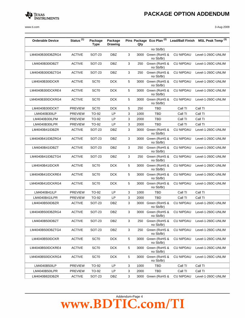
LM4040B82IDBZR ACTIVE SOT-23 DBZ 3 3000 Green (RoHS & CU NIPDAU Level-1-260C-UNLIM
PACKAGE OPTION ADDENDUM
www.ti.com 3-Aug-2009
Addendum-Page 4
www.BDTIC.com/TI

Orderable Device Status (1) PackageType
PackageDrawing
Pins PackageQty
Eco Plan (2) Lead/Ball Finish MSL Peak Temp (3)
no Sb/Br)
LM4040B82IDBZRG4 ACTIVE SOT-23 DBZ 3 3000 Green (RoHS &no Sb/Br)
CU NIPDAU Level-1-260C-UNLIM
LM4040B82IDBZT ACTIVE SOT-23 DBZ 3 250 Green (RoHS &no Sb/Br)
CU NIPDAU Level-1-260C-UNLIM
LM4040B82IDBZTG4 ACTIVE SOT-23 DBZ 3 250 Green (RoHS &no Sb/Br)
CU NIPDAU Level-1-260C-UNLIM
LM4040B82IDCKR ACTIVE SC70 DCK 5 3000 Green (RoHS &no Sb/Br)
CU NIPDAU Level-1-260C-UNLIM
LM4040B82IDCKRG4 ACTIVE SC70 DCK 5 3000 Green (RoHS &no Sb/Br)
CU NIPDAU Level-1-260C-UNLIM
LM4040C10IDBZR ACTIVE SOT-23 DBZ 3 3000 Green (RoHS &no Sb/Br)
CU NIPDAU Level-1-260C-UNLIM
LM4040C10IDBZRG4 ACTIVE SOT-23 DBZ 3 3000 Green (RoHS &no Sb/Br)
CU NIPDAU Level-1-260C-UNLIM
LM4040C10IDBZT ACTIVE SOT-23 DBZ 3 250 Green (RoHS &no Sb/Br)
CU NIPDAU Level-1-260C-UNLIM
LM4040C10IDBZTG4 ACTIVE SOT-23 DBZ 3 250 Green (RoHS &no Sb/Br)
CU NIPDAU Level-1-260C-UNLIM
LM4040C10IDCKR ACTIVE SC70 DCK 5 3000 Green (RoHS &no Sb/Br)
CU NIPDAU Level-1-260C-UNLIM
LM4040C10IDCKRG4 ACTIVE SC70 DCK 5 3000 Green (RoHS &no Sb/Br)
CU NIPDAU Level-1-260C-UNLIM
LM4040C10ILP ACTIVE TO-92 LP 3 1000 Pb-Free(RoHS)
CU SN N / A for Pkg Type
LM4040C10ILPE3 ACTIVE TO-92 LP 3 1000 Pb-Free(RoHS)
CU SN N / A for Pkg Type
LM4040C10ILPR ACTIVE TO-92 LP 3 2000 Pb-Free(RoHS)
CU SN N / A for Pkg Type
LM4040C10ILPRE3 ACTIVE TO-92 LP 3 2000 Pb-Free(RoHS)
CU SN N / A for Pkg Type
LM4040C20IDBZR ACTIVE SOT-23 DBZ 3 3000 Green (RoHS &no Sb/Br)
CU NIPDAU Level-1-260C-UNLIM
LM4040C20IDBZRG4 ACTIVE SOT-23 DBZ 3 3000 Green (RoHS &no Sb/Br)
CU NIPDAU Level-1-260C-UNLIM
LM4040C20IDBZT ACTIVE SOT-23 DBZ 3 250 Green (RoHS &no Sb/Br)
CU NIPDAU Level-1-260C-UNLIM
LM4040C20IDBZTG4 ACTIVE SOT-23 DBZ 3 250 Green (RoHS &no Sb/Br)
CU NIPDAU Level-1-260C-UNLIM
LM4040C20IDCKR ACTIVE SC70 DCK 5 3000 Green (RoHS &no Sb/Br)
CU NIPDAU Level-1-260C-UNLIM
LM4040C20IDCKRE4 ACTIVE SC70 DCK 5 3000 Green (RoHS &no Sb/Br)
CU NIPDAU Level-1-260C-UNLIM
LM4040C20IDCKRG4 ACTIVE SC70 DCK 5 3000 Green (RoHS &no Sb/Br)
CU NIPDAU Level-1-260C-UNLIM
LM4040C20ILP ACTIVE TO-92 LP 3 1000 Pb-Free(RoHS)
CU SN N / A for Pkg Type
LM4040C20ILPE3 ACTIVE TO-92 LP 3 1000 Pb-Free(RoHS)
CU SN N / A for Pkg Type
LM4040C20ILPR ACTIVE TO-92 LP 3 2000 Pb-Free(RoHS)
CU SN N / A for Pkg Type
PACKAGE OPTION ADDENDUM
www.ti.com 3-Aug-2009
Addendum-Page 5
www.BDTIC.com/TI
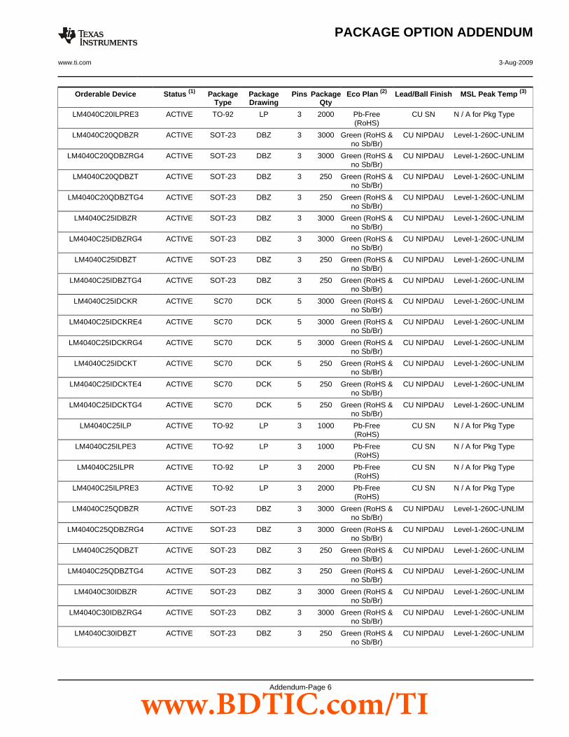
Orderable Device Status (1) PackageType
PackageDrawing
Pins PackageQty
Eco Plan (2) Lead/Ball Finish MSL Peak Temp (3)
LM4040C20ILPRE3 ACTIVE TO-92 LP 3 2000 Pb-Free(RoHS)
CU SN N / A for Pkg Type
LM4040C20QDBZR ACTIVE SOT-23 DBZ 3 3000 Green (RoHS &no Sb/Br)
CU NIPDAU Level-1-260C-UNLIM
LM4040C20QDBZRG4 ACTIVE SOT-23 DBZ 3 3000 Green (RoHS &no Sb/Br)
CU NIPDAU Level-1-260C-UNLIM
LM4040C20QDBZT ACTIVE SOT-23 DBZ 3 250 Green (RoHS &no Sb/Br)
CU NIPDAU Level-1-260C-UNLIM
LM4040C20QDBZTG4 ACTIVE SOT-23 DBZ 3 250 Green (RoHS &no Sb/Br)
CU NIPDAU Level-1-260C-UNLIM
LM4040C25IDBZR ACTIVE SOT-23 DBZ 3 3000 Green (RoHS &no Sb/Br)
CU NIPDAU Level-1-260C-UNLIM
LM4040C25IDBZRG4 ACTIVE SOT-23 DBZ 3 3000 Green (RoHS &no Sb/Br)
CU NIPDAU Level-1-260C-UNLIM
LM4040C25IDBZT ACTIVE SOT-23 DBZ 3 250 Green (RoHS &no Sb/Br)
CU NIPDAU Level-1-260C-UNLIM
LM4040C25IDBZTG4 ACTIVE SOT-23 DBZ 3 250 Green (RoHS &no Sb/Br)
CU NIPDAU Level-1-260C-UNLIM
LM4040C25IDCKR ACTIVE SC70 DCK 5 3000 Green (RoHS &no Sb/Br)
CU NIPDAU Level-1-260C-UNLIM
LM4040C25IDCKRE4 ACTIVE SC70 DCK 5 3000 Green (RoHS &no Sb/Br)
CU NIPDAU Level-1-260C-UNLIM
LM4040C25IDCKRG4 ACTIVE SC70 DCK 5 3000 Green (RoHS &no Sb/Br)
CU NIPDAU Level-1-260C-UNLIM
LM4040C25IDCKT ACTIVE SC70 DCK 5 250 Green (RoHS &no Sb/Br)
CU NIPDAU Level-1-260C-UNLIM
LM4040C25IDCKTE4 ACTIVE SC70 DCK 5 250 Green (RoHS &no Sb/Br)
CU NIPDAU Level-1-260C-UNLIM
LM4040C25IDCKTG4 ACTIVE SC70 DCK 5 250 Green (RoHS &no Sb/Br)
CU NIPDAU Level-1-260C-UNLIM
LM4040C25ILP ACTIVE TO-92 LP 3 1000 Pb-Free(RoHS)
CU SN N / A for Pkg Type
LM4040C25ILPE3 ACTIVE TO-92 LP 3 1000 Pb-Free(RoHS)
CU SN N / A for Pkg Type
LM4040C25ILPR ACTIVE TO-92 LP 3 2000 Pb-Free(RoHS)
CU SN N / A for Pkg Type
LM4040C25ILPRE3 ACTIVE TO-92 LP 3 2000 Pb-Free(RoHS)
CU SN N / A for Pkg Type
LM4040C25QDBZR ACTIVE SOT-23 DBZ 3 3000 Green (RoHS &no Sb/Br)
CU NIPDAU Level-1-260C-UNLIM
LM4040C25QDBZRG4 ACTIVE SOT-23 DBZ 3 3000 Green (RoHS &no Sb/Br)
CU NIPDAU Level-1-260C-UNLIM
LM4040C25QDBZT ACTIVE SOT-23 DBZ 3 250 Green (RoHS &no Sb/Br)
CU NIPDAU Level-1-260C-UNLIM
LM4040C25QDBZTG4 ACTIVE SOT-23 DBZ 3 250 Green (RoHS &no Sb/Br)
CU NIPDAU Level-1-260C-UNLIM
LM4040C30IDBZR ACTIVE SOT-23 DBZ 3 3000 Green (RoHS &no Sb/Br)
CU NIPDAU Level-1-260C-UNLIM
LM4040C30IDBZRG4 ACTIVE SOT-23 DBZ 3 3000 Green (RoHS &no Sb/Br)
CU NIPDAU Level-1-260C-UNLIM
LM4040C30IDBZT ACTIVE SOT-23 DBZ 3 250 Green (RoHS &no Sb/Br)
CU NIPDAU Level-1-260C-UNLIM
PACKAGE OPTION ADDENDUM
www.ti.com 3-Aug-2009
Addendum-Page 6
www.BDTIC.com/TI
Orderable Device Status (1) PackageType
PackageDrawing
Pins PackageQty
Eco Plan (2) Lead/Ball Finish MSL Peak Temp (3)
LM4040C30IDBZTG4 ACTIVE SOT-23 DBZ 3 250 Green (RoHS &no Sb/Br)
CU NIPDAU Level-1-260C-UNLIM
LM4040C30IDCKR ACTIVE SC70 DCK 5 3000 Green (RoHS &no Sb/Br)
CU NIPDAU Level-1-260C-UNLIM
LM4040C30IDCKRE4 ACTIVE SC70 DCK 5 3000 Green (RoHS &no Sb/Br)
CU NIPDAU Level-1-260C-UNLIM
LM4040C30IDCKRG4 ACTIVE SC70 DCK 5 3000 Green (RoHS &no Sb/Br)
CU NIPDAU Level-1-260C-UNLIM
LM4040C30IDCKT PREVIEW SC70 DCK 5 250 TBD Call TI Call TI
LM4040C30ILP ACTIVE TO-92 LP 3 1000 Pb-Free(RoHS)
CU SN N / A for Pkg Type
LM4040C30ILPE3 ACTIVE TO-92 LP 3 1000 Pb-Free(RoHS)
CU SN N / A for Pkg Type
LM4040C30ILPM PREVIEW TO-92 LP 3 2000 TBD Call TI Call TI
LM4040C30ILPR ACTIVE TO-92 LP 3 2000 Pb-Free(RoHS)
CU SN N / A for Pkg Type
LM4040C30ILPRE3 ACTIVE TO-92 LP 3 2000 Pb-Free(RoHS)
CU SN N / A for Pkg Type
LM4040C30QDBZR ACTIVE SOT-23 DBZ 3 3000 Green (RoHS &no Sb/Br)
CU NIPDAU Level-1-260C-UNLIM
LM4040C30QDBZRG4 ACTIVE SOT-23 DBZ 3 3000 Green (RoHS &no Sb/Br)
CU NIPDAU Level-1-260C-UNLIM
LM4040C30QDBZT ACTIVE SOT-23 DBZ 3 250 Green (RoHS &no Sb/Br)
CU NIPDAU Level-1-260C-UNLIM
LM4040C30QDBZTG4 ACTIVE SOT-23 DBZ 3 250 Green (RoHS &no Sb/Br)
CU NIPDAU Level-1-260C-UNLIM
LM4040C41IDBZR ACTIVE SOT-23 DBZ 3 3000 Green (RoHS &no Sb/Br)
CU NIPDAU Level-1-260C-UNLIM
LM4040C41IDBZRG4 ACTIVE SOT-23 DBZ 3 3000 Green (RoHS &no Sb/Br)
CU NIPDAU Level-1-260C-UNLIM
LM4040C41IDBZT ACTIVE SOT-23 DBZ 3 250 Green (RoHS &no Sb/Br)
CU NIPDAU Level-1-260C-UNLIM
LM4040C41IDBZTG4 ACTIVE SOT-23 DBZ 3 250 Green (RoHS &no Sb/Br)
CU NIPDAU Level-1-260C-UNLIM
LM4040C41IDCKR ACTIVE SC70 DCK 5 3000 Green (RoHS &no Sb/Br)
CU NIPDAU Level-1-260C-UNLIM
LM4040C41IDCKRE4 ACTIVE SC70 DCK 5 3000 Green (RoHS &no Sb/Br)
CU NIPDAU Level-1-260C-UNLIM
LM4040C41IDCKRG4 ACTIVE SC70 DCK 5 3000 Green (RoHS &no Sb/Br)
CU NIPDAU Level-1-260C-UNLIM
LM4040C41ILP ACTIVE TO-92 LP 3 1000 Pb-Free(RoHS)
CU SN N / A for Pkg Type
LM4040C41ILPE3 ACTIVE TO-92 LP 3 1000 Pb-Free(RoHS)
CU SN N / A for Pkg Type
LM4040C41ILPR ACTIVE TO-92 LP 3 2000 Pb-Free(RoHS)
CU SN N / A for Pkg Type
LM4040C41ILPRE3 ACTIVE TO-92 LP 3 2000 Pb-Free(RoHS)
CU SN N / A for Pkg Type
LM4040C50IDBZR ACTIVE SOT-23 DBZ 3 3000 Green (RoHS &no Sb/Br)
CU NIPDAU Level-1-260C-UNLIM
LM4040C50IDBZRG4 ACTIVE SOT-23 DBZ 3 3000 Green (RoHS & CU NIPDAU Level-1-260C-UNLIM
PACKAGE OPTION ADDENDUM
www.ti.com 3-Aug-2009
Addendum-Page 7
www.BDTIC.com/TI
Orderable Device Status (1) PackageType
PackageDrawing
Pins PackageQty
Eco Plan (2) Lead/Ball Finish MSL Peak Temp (3)
no Sb/Br)
LM4040C50IDBZT ACTIVE SOT-23 DBZ 3 250 Green (RoHS &no Sb/Br)
CU NIPDAU Level-1-260C-UNLIM
LM4040C50IDBZTG4 ACTIVE SOT-23 DBZ 3 250 Green (RoHS &no Sb/Br)
CU NIPDAU Level-1-260C-UNLIM
LM4040C50IDCKR ACTIVE SC70 DCK 5 3000 Green (RoHS &no Sb/Br)
CU NIPDAU Level-1-260C-UNLIM
LM4040C50IDCKRE4 ACTIVE SC70 DCK 5 3000 Green (RoHS &no Sb/Br)
CU NIPDAU Level-1-260C-UNLIM
LM4040C50IDCKRG4 ACTIVE SC70 DCK 5 3000 Green (RoHS &no Sb/Br)
CU NIPDAU Level-1-260C-UNLIM
LM4040C50ILP ACTIVE TO-92 LP 3 1000 Pb-Free(RoHS)
CU SN N / A for Pkg Type
LM4040C50ILPE3 ACTIVE TO-92 LP 3 1000 Pb-Free(RoHS)
CU SN N / A for Pkg Type
LM4040C50ILPR ACTIVE TO-92 LP 3 2000 Pb-Free(RoHS)
CU SN N / A for Pkg Type
LM4040C50ILPRE3 ACTIVE TO-92 LP 3 2000 Pb-Free(RoHS)
CU SN N / A for Pkg Type
LM4040C50QDBZR ACTIVE SOT-23 DBZ 3 3000 Green (RoHS &no Sb/Br)
CU NIPDAU Level-1-260C-UNLIM
LM4040C50QDBZRG4 ACTIVE SOT-23 DBZ 3 3000 Green (RoHS &no Sb/Br)
CU NIPDAU Level-1-260C-UNLIM
LM4040C50QDBZT ACTIVE SOT-23 DBZ 3 250 Green (RoHS &no Sb/Br)
CU NIPDAU Level-1-260C-UNLIM
LM4040C50QDBZTG4 ACTIVE SOT-23 DBZ 3 250 Green (RoHS &no Sb/Br)
CU NIPDAU Level-1-260C-UNLIM
LM4040C82IDBZR ACTIVE SOT-23 DBZ 3 3000 Green (RoHS &no Sb/Br)
CU NIPDAU Level-1-260C-UNLIM
LM4040C82IDBZRG4 ACTIVE SOT-23 DBZ 3 3000 Green (RoHS &no Sb/Br)
CU NIPDAU Level-1-260C-UNLIM
LM4040C82IDBZT ACTIVE SOT-23 DBZ 3 250 Green (RoHS &no Sb/Br)
CU NIPDAU Level-1-260C-UNLIM
LM4040C82IDBZTG4 ACTIVE SOT-23 DBZ 3 250 Green (RoHS &no Sb/Br)
CU NIPDAU Level-1-260C-UNLIM
LM4040C82IDCKR ACTIVE SC70 DCK 5 3000 Green (RoHS &no Sb/Br)
CU NIPDAU Level-1-260C-UNLIM
LM4040C82IDCKRG4 ACTIVE SC70 DCK 5 3000 Green (RoHS &no Sb/Br)
CU NIPDAU Level-1-260C-UNLIM
LM4040C82ILP ACTIVE TO-92 LP 3 1000 Pb-Free(RoHS)
CU SN N / A for Pkg Type
LM4040C82ILPE3 ACTIVE TO-92 LP 3 1000 Pb-Free(RoHS)
CU SN N / A for Pkg Type
LM4040C82ILPR ACTIVE TO-92 LP 3 2000 Pb-Free(RoHS)
CU SN N / A for Pkg Type
LM4040C82ILPRE3 ACTIVE TO-92 LP 3 2000 Pb-Free(RoHS)
CU SN N / A for Pkg Type
LM4040D20IDBZR ACTIVE SOT-23 DBZ 3 3000 Green (RoHS &no Sb/Br)
CU NIPDAU Level-1-260C-UNLIM
LM4040D20IDBZRG4 ACTIVE SOT-23 DBZ 3 3000 Green (RoHS &no Sb/Br)
CU NIPDAU Level-1-260C-UNLIM
PACKAGE OPTION ADDENDUM
www.ti.com 3-Aug-2009
Addendum-Page 8
www.BDTIC.com/TI
Orderable Device Status (1) PackageType
PackageDrawing
Pins PackageQty
Eco Plan (2) Lead/Ball Finish MSL Peak Temp (3)
LM4040D20IDBZT ACTIVE SOT-23 DBZ 3 250 Green (RoHS &no Sb/Br)
CU NIPDAU Level-1-260C-UNLIM
LM4040D20IDBZTG4 ACTIVE SOT-23 DBZ 3 250 Green (RoHS &no Sb/Br)
CU NIPDAU Level-1-260C-UNLIM
LM4040D20IDCKR ACTIVE SC70 DCK 5 3000 Green (RoHS &no Sb/Br)
CU NIPDAU Level-1-260C-UNLIM
LM4040D20IDCKRE4 ACTIVE SC70 DCK 5 3000 Green (RoHS &no Sb/Br)
CU NIPDAU Level-1-260C-UNLIM
LM4040D20IDCKRG4 ACTIVE SC70 DCK 5 3000 Green (RoHS &no Sb/Br)
CU NIPDAU Level-1-260C-UNLIM
LM4040D20ILP ACTIVE TO-92 LP 3 1000 Pb-Free(RoHS)
CU SN N / A for Pkg Type
LM4040D20ILPE3 ACTIVE TO-92 LP 3 1000 Pb-Free(RoHS)
CU SN N / A for Pkg Type
LM4040D20ILPR ACTIVE TO-92 LP 3 2000 Pb-Free(RoHS)
CU SN N / A for Pkg Type
LM4040D20ILPRE3 ACTIVE TO-92 LP 3 2000 Pb-Free(RoHS)
CU SN N / A for Pkg Type
LM4040D20QDBZR ACTIVE SOT-23 DBZ 3 3000 Green (RoHS &no Sb/Br)
CU NIPDAU Level-1-260C-UNLIM
LM4040D20QDBZRG4 ACTIVE SOT-23 DBZ 3 3000 Green (RoHS &no Sb/Br)
CU NIPDAU Level-1-260C-UNLIM
LM4040D20QDBZT ACTIVE SOT-23 DBZ 3 250 Green (RoHS &no Sb/Br)
CU NIPDAU Level-1-260C-UNLIM
LM4040D20QDBZTG4 ACTIVE SOT-23 DBZ 3 250 Green (RoHS &no Sb/Br)
CU NIPDAU Level-1-260C-UNLIM
LM4040D25IDBZR ACTIVE SOT-23 DBZ 3 3000 Green (RoHS &no Sb/Br)
CU NIPDAU Level-1-260C-UNLIM
LM4040D25IDBZRG4 ACTIVE SOT-23 DBZ 3 3000 Green (RoHS &no Sb/Br)
CU NIPDAU Level-1-260C-UNLIM
LM4040D25IDBZT ACTIVE SOT-23 DBZ 3 250 Green (RoHS &no Sb/Br)
CU NIPDAU Level-1-260C-UNLIM
LM4040D25IDBZTG4 ACTIVE SOT-23 DBZ 3 250 Green (RoHS &no Sb/Br)
CU NIPDAU Level-1-260C-UNLIM
LM4040D25IDCKR ACTIVE SC70 DCK 5 3000 Green (RoHS &no Sb/Br)
CU NIPDAU Level-1-260C-UNLIM
LM4040D25IDCKRE4 ACTIVE SC70 DCK 5 3000 Green (RoHS &no Sb/Br)
CU NIPDAU Level-1-260C-UNLIM
LM4040D25IDCKRG4 ACTIVE SC70 DCK 5 3000 Green (RoHS &no Sb/Br)
CU NIPDAU Level-1-260C-UNLIM
LM4040D25IDCKT ACTIVE SC70 DCK 5 250 Green (RoHS &no Sb/Br)
CU NIPDAU Level-1-260C-UNLIM
LM4040D25IDCKTE4 ACTIVE SC70 DCK 5 250 Green (RoHS &no Sb/Br)
CU NIPDAU Level-1-260C-UNLIM
LM4040D25IDCKTG4 ACTIVE SC70 DCK 5 250 Green (RoHS &no Sb/Br)
CU NIPDAU Level-1-260C-UNLIM
LM4040D25ILP ACTIVE TO-92 LP 3 1000 Pb-Free(RoHS)
CU SN N / A for Pkg Type
LM4040D25ILPE3 ACTIVE TO-92 LP 3 1000 Pb-Free(RoHS)
CU SN N / A for Pkg Type
LM4040D25ILPR ACTIVE TO-92 LP 3 2000 Pb-Free(RoHS)
CU SN N / A for Pkg Type
PACKAGE OPTION ADDENDUM
www.ti.com 3-Aug-2009
Addendum-Page 9
www.BDTIC.com/TI

Orderable Device Status (1) PackageType
PackageDrawing
Pins PackageQty
Eco Plan (2) Lead/Ball Finish MSL Peak Temp (3)
LM4040D25ILPRE3 ACTIVE TO-92 LP 3 2000 Pb-Free(RoHS)
CU SN N / A for Pkg Type
LM4040D25QDBZR ACTIVE SOT-23 DBZ 3 3000 Green (RoHS &no Sb/Br)
CU NIPDAU Level-1-260C-UNLIM
LM4040D25QDBZRG4 ACTIVE SOT-23 DBZ 3 3000 Green (RoHS &no Sb/Br)
CU NIPDAU Level-1-260C-UNLIM
LM4040D25QDBZT ACTIVE SOT-23 DBZ 3 250 Green (RoHS &no Sb/Br)
CU NIPDAU Level-1-260C-UNLIM
LM4040D25QDBZTG4 ACTIVE SOT-23 DBZ 3 250 Green (RoHS &no Sb/Br)
CU NIPDAU Level-1-260C-UNLIM
LM4040D30IDBZR ACTIVE SOT-23 DBZ 3 3000 Green (RoHS &no Sb/Br)
CU NIPDAU Level-1-260C-UNLIM
LM4040D30IDBZRG4 ACTIVE SOT-23 DBZ 3 3000 Green (RoHS &no Sb/Br)
CU NIPDAU Level-1-260C-UNLIM
LM4040D30IDBZT ACTIVE SOT-23 DBZ 3 250 Green (RoHS &no Sb/Br)
CU NIPDAU Level-1-260C-UNLIM
LM4040D30IDBZTG4 ACTIVE SOT-23 DBZ 3 250 Green (RoHS &no Sb/Br)
CU NIPDAU Level-1-260C-UNLIM
LM4040D30IDCKR ACTIVE SC70 DCK 5 3000 Green (RoHS &no Sb/Br)
CU NIPDAU Level-1-260C-UNLIM
LM4040D30IDCKRE4 ACTIVE SC70 DCK 5 3000 Green (RoHS &no Sb/Br)
CU NIPDAU Level-1-260C-UNLIM
LM4040D30IDCKRG4 ACTIVE SC70 DCK 5 3000 Green (RoHS &no Sb/Br)
CU NIPDAU Level-1-260C-UNLIM
LM4040D30IDCKT PREVIEW SC70 DCK 5 250 TBD Call TI Call TI
LM4040D30ILP ACTIVE TO-92 LP 3 1000 Pb-Free(RoHS)
CU SN N / A for Pkg Type
LM4040D30ILPE3 ACTIVE TO-92 LP 3 1000 Pb-Free(RoHS)
CU SN N / A for Pkg Type
LM4040D30ILPM PREVIEW TO-92 LP 3 2000 TBD Call TI Call TI
LM4040D30ILPR ACTIVE TO-92 LP 3 2000 Pb-Free(RoHS)
CU SN N / A for Pkg Type
LM4040D30ILPRE3 ACTIVE TO-92 LP 3 2000 Pb-Free(RoHS)
CU SN N / A for Pkg Type
LM4040D30QDBZR ACTIVE SOT-23 DBZ 3 3000 Green (RoHS &no Sb/Br)
CU NIPDAU Level-1-260C-UNLIM
LM4040D30QDBZRG4 ACTIVE SOT-23 DBZ 3 3000 Green (RoHS &no Sb/Br)
CU NIPDAU Level-1-260C-UNLIM
LM4040D30QDBZT ACTIVE SOT-23 DBZ 3 250 Green (RoHS &no Sb/Br)
CU NIPDAU Level-1-260C-UNLIM
LM4040D30QDBZTG4 ACTIVE SOT-23 DBZ 3 250 Green (RoHS &no Sb/Br)
CU NIPDAU Level-1-260C-UNLIM
LM4040D41IDBZR ACTIVE SOT-23 DBZ 3 3000 Green (RoHS &no Sb/Br)
CU NIPDAU Level-1-260C-UNLIM
LM4040D41IDBZRG4 ACTIVE SOT-23 DBZ 3 3000 Green (RoHS &no Sb/Br)
CU NIPDAU Level-1-260C-UNLIM
LM4040D41IDBZT ACTIVE SOT-23 DBZ 3 250 Green (RoHS &no Sb/Br)
CU NIPDAU Level-1-260C-UNLIM
LM4040D41IDBZTG4 ACTIVE SOT-23 DBZ 3 250 Green (RoHS &no Sb/Br)
CU NIPDAU Level-1-260C-UNLIM
LM4040D41IDCKR ACTIVE SC70 DCK 5 3000 Green (RoHS & CU NIPDAU Level-1-260C-UNLIM
PACKAGE OPTION ADDENDUM
www.ti.com 3-Aug-2009
Addendum-Page 10
www.BDTIC.com/TI
Orderable Device Status (1) PackageType
PackageDrawing
Pins PackageQty
Eco Plan (2) Lead/Ball Finish MSL Peak Temp (3)
no Sb/Br)
LM4040D41IDCKRE4 ACTIVE SC70 DCK 5 3000 Green (RoHS &no Sb/Br)
CU NIPDAU Level-1-260C-UNLIM
LM4040D41IDCKRG4 ACTIVE SC70 DCK 5 3000 Green (RoHS &no Sb/Br)
CU NIPDAU Level-1-260C-UNLIM
LM4040D41ILP ACTIVE TO-92 LP 3 1000 Pb-Free(RoHS)
CU SN N / A for Pkg Type
LM4040D41ILPE3 ACTIVE TO-92 LP 3 1000 Pb-Free(RoHS)
CU SN N / A for Pkg Type
LM4040D41ILPR ACTIVE TO-92 LP 3 2000 Pb-Free(RoHS)
CU SN N / A for Pkg Type
LM4040D41ILPRE3 ACTIVE TO-92 LP 3 2000 Pb-Free(RoHS)
CU SN N / A for Pkg Type
LM4040D50IDBZR ACTIVE SOT-23 DBZ 3 3000 Green (RoHS &no Sb/Br)
CU NIPDAU Level-1-260C-UNLIM
LM4040D50IDBZRG4 ACTIVE SOT-23 DBZ 3 3000 Green (RoHS &no Sb/Br)
CU NIPDAU Level-1-260C-UNLIM
LM4040D50IDBZT ACTIVE SOT-23 DBZ 3 250 Green (RoHS &no Sb/Br)
CU NIPDAU Level-1-260C-UNLIM
LM4040D50IDBZTG4 ACTIVE SOT-23 DBZ 3 250 Green (RoHS &no Sb/Br)
CU NIPDAU Level-1-260C-UNLIM
LM4040D50IDCKR ACTIVE SC70 DCK 5 3000 Green (RoHS &no Sb/Br)
CU NIPDAU Level-1-260C-UNLIM
LM4040D50IDCKRE4 ACTIVE SC70 DCK 5 3000 Green (RoHS &no Sb/Br)
CU NIPDAU Level-1-260C-UNLIM
LM4040D50IDCKRG4 ACTIVE SC70 DCK 5 3000 Green (RoHS &no Sb/Br)
CU NIPDAU Level-1-260C-UNLIM
LM4040D50ILP ACTIVE TO-92 LP 3 1000 Pb-Free(RoHS)
CU SN N / A for Pkg Type
LM4040D50ILPE3 ACTIVE TO-92 LP 3 1000 Pb-Free(RoHS)
CU SN N / A for Pkg Type
LM4040D50ILPR ACTIVE TO-92 LP 3 2000 Pb-Free(RoHS)
CU SN N / A for Pkg Type
LM4040D50ILPRE3 ACTIVE TO-92 LP 3 2000 Pb-Free(RoHS)
CU SN N / A for Pkg Type
LM4040D50QDBZR ACTIVE SOT-23 DBZ 3 3000 Green (RoHS &no Sb/Br)
CU NIPDAU Level-1-260C-UNLIM
LM4040D50QDBZRG4 ACTIVE SOT-23 DBZ 3 3000 Green (RoHS &no Sb/Br)
CU NIPDAU Level-1-260C-UNLIM
LM4040D50QDBZT ACTIVE SOT-23 DBZ 3 250 Green (RoHS &no Sb/Br)
CU NIPDAU Level-1-260C-UNLIM
LM4040D50QDBZTG4 ACTIVE SOT-23 DBZ 3 250 Green (RoHS &no Sb/Br)
CU NIPDAU Level-1-260C-UNLIM
LM4040D82IDBZR ACTIVE SOT-23 DBZ 3 3000 Green (RoHS &no Sb/Br)
CU NIPDAU Level-1-260C-UNLIM
LM4040D82IDBZRG4 ACTIVE SOT-23 DBZ 3 3000 Green (RoHS &no Sb/Br)
CU NIPDAU Level-1-260C-UNLIM
LM4040D82IDBZT ACTIVE SOT-23 DBZ 3 250 Green (RoHS &no Sb/Br)
CU NIPDAU Level-1-260C-UNLIM
LM4040D82IDBZTG4 ACTIVE SOT-23 DBZ 3 250 Green (RoHS &no Sb/Br)
CU NIPDAU Level-1-260C-UNLIM
PACKAGE OPTION ADDENDUM
www.ti.com 3-Aug-2009
Addendum-Page 11
www.BDTIC.com/TI
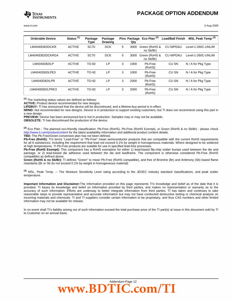
Orderable Device Status (1) PackageType
PackageDrawing
Pins PackageQty
Eco Plan (2) Lead/Ball Finish MSL Peak Temp (3)
LM4040D82IDCKR ACTIVE SC70 DCK 5 3000 Green (RoHS &no Sb/Br)
CU NIPDAU Level-1-260C-UNLIM
LM4040D82IDCKRG4 ACTIVE SC70 DCK 5 3000 Green (RoHS &no Sb/Br)
CU NIPDAU Level-1-260C-UNLIM
LM4040D82ILP ACTIVE TO-92 LP 3 1000 Pb-Free(RoHS)
CU SN N / A for Pkg Type
LM4040D82ILPE3 ACTIVE TO-92 LP 3 1000 Pb-Free(RoHS)
CU SN N / A for Pkg Type
LM4040D82ILPR ACTIVE TO-92 LP 3 2000 Pb-Free(RoHS)
CU SN N / A for Pkg Type
LM4040D82ILPRE3 ACTIVE TO-92 LP 3 2000 Pb-Free(RoHS)
CU SN N / A for Pkg Type
(1) The marketing status values are defined as follows:ACTIVE: Product device recommended for new designs.LIFEBUY: TI has announced that the device will be discontinued, and a lifetime-buy period is in effect.NRND: Not recommended for new designs. Device is in production to support existing customers, but TI does not recommend using this part ina new design.PREVIEW: Device has been announced but is not in production. Samples may or may not be available.OBSOLETE: TI has discontinued the production of the device.
(2) Eco Plan - The planned eco-friendly classification: Pb-Free (RoHS), Pb-Free (RoHS Exempt), or Green (RoHS & no Sb/Br) - please checkhttp://www.ti.com/productcontent for the latest availability information and additional product content details.TBD: The Pb-Free/Green conversion plan has not been defined.Pb-Free (RoHS): TI's terms "Lead-Free" or "Pb-Free" mean semiconductor products that are compatible with the current RoHS requirementsfor all 6 substances, including the requirement that lead not exceed 0.1% by weight in homogeneous materials. Where designed to be solderedat high temperatures, TI Pb-Free products are suitable for use in specified lead-free processes.Pb-Free (RoHS Exempt): This component has a RoHS exemption for either 1) lead-based flip-chip solder bumps used between the die andpackage, or 2) lead-based die adhesive used between the die and leadframe. The component is otherwise considered Pb-Free (RoHScompatible) as defined above.Green (RoHS & no Sb/Br): TI defines "Green" to mean Pb-Free (RoHS compatible), and free of Bromine (Br) and Antimony (Sb) based flameretardants (Br or Sb do not exceed 0.1% by weight in homogeneous material)
(3) MSL, Peak Temp. -- The Moisture Sensitivity Level rating according to the JEDEC industry standard classifications, and peak soldertemperature.
Important Information and Disclaimer:The information provided on this page represents TI's knowledge and belief as of the date that it isprovided. TI bases its knowledge and belief on information provided by third parties, and makes no representation or warranty as to theaccuracy of such information. Efforts are underway to better integrate information from third parties. TI has taken and continues to takereasonable steps to provide representative and accurate information but may not have conducted destructive testing or chemical analysis onincoming materials and chemicals. TI and TI suppliers consider certain information to be proprietary, and thus CAS numbers and other limitedinformation may not be available for release.
In no event shall TI's liability arising out of such information exceed the total purchase price of the TI part(s) at issue in this document sold by TIto Customer on an annual basis.
PACKAGE OPTION ADDENDUM
www.ti.com 3-Aug-2009
Addendum-Page 12
www.BDTIC.com/TI
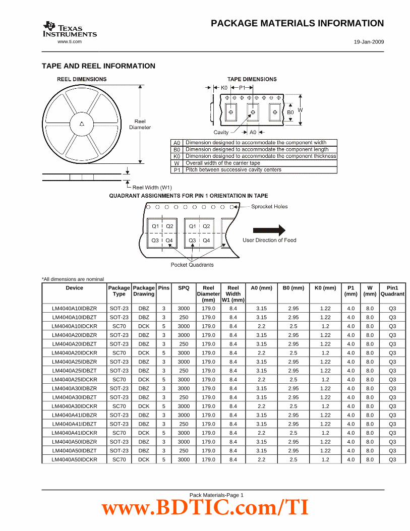
TAPE AND REEL INFORMATION
*All dimensions are nominal
Device PackageType
PackageDrawing
Pins SPQ ReelDiameter
(mm)
ReelWidth
W1 (mm)
A0 (mm) B0 (mm) K0 (mm) P1(mm)
W(mm)
Pin1Quadrant
LM4040A10IDBZR SOT-23 DBZ 3 3000 179.0 8.4 3.15 2.95 1.22 4.0 8.0 Q3
LM4040A10IDBZT SOT-23 DBZ 3 250 179.0 8.4 3.15 2.95 1.22 4.0 8.0 Q3
LM4040A10IDCKR SC70 DCK 5 3000 179.0 8.4 2.2 2.5 1.2 4.0 8.0 Q3
LM4040A20IDBZR SOT-23 DBZ 3 3000 179.0 8.4 3.15 2.95 1.22 4.0 8.0 Q3
LM4040A20IDBZT SOT-23 DBZ 3 250 179.0 8.4 3.15 2.95 1.22 4.0 8.0 Q3
LM4040A20IDCKR SC70 DCK 5 3000 179.0 8.4 2.2 2.5 1.2 4.0 8.0 Q3
LM4040A25IDBZR SOT-23 DBZ 3 3000 179.0 8.4 3.15 2.95 1.22 4.0 8.0 Q3
LM4040A25IDBZT SOT-23 DBZ 3 250 179.0 8.4 3.15 2.95 1.22 4.0 8.0 Q3
LM4040A25IDCKR SC70 DCK 5 3000 179.0 8.4 2.2 2.5 1.2 4.0 8.0 Q3
LM4040A30IDBZR SOT-23 DBZ 3 3000 179.0 8.4 3.15 2.95 1.22 4.0 8.0 Q3
LM4040A30IDBZT SOT-23 DBZ 3 250 179.0 8.4 3.15 2.95 1.22 4.0 8.0 Q3
LM4040A30IDCKR SC70 DCK 5 3000 179.0 8.4 2.2 2.5 1.2 4.0 8.0 Q3
LM4040A41IDBZR SOT-23 DBZ 3 3000 179.0 8.4 3.15 2.95 1.22 4.0 8.0 Q3
LM4040A41IDBZT SOT-23 DBZ 3 250 179.0 8.4 3.15 2.95 1.22 4.0 8.0 Q3
LM4040A41IDCKR SC70 DCK 5 3000 179.0 8.4 2.2 2.5 1.2 4.0 8.0 Q3
LM4040A50IDBZR SOT-23 DBZ 3 3000 179.0 8.4 3.15 2.95 1.22 4.0 8.0 Q3
LM4040A50IDBZT SOT-23 DBZ 3 250 179.0 8.4 3.15 2.95 1.22 4.0 8.0 Q3
LM4040A50IDCKR SC70 DCK 5 3000 179.0 8.4 2.2 2.5 1.2 4.0 8.0 Q3
PACKAGE MATERIALS INFORMATION
www.ti.com 19-Jan-2009
Pack Materials-Page 1
www.BDTIC.com/TI

Device PackageType
PackageDrawing
Pins SPQ ReelDiameter
(mm)
ReelWidth
W1 (mm)
A0 (mm) B0 (mm) K0 (mm) P1(mm)
W(mm)
Pin1Quadrant
LM4040A82IDBZR SOT-23 DBZ 3 3000 179.0 8.4 3.15 2.95 1.22 4.0 8.0 Q3
LM4040A82IDBZT SOT-23 DBZ 3 250 179.0 8.4 3.15 2.95 1.22 4.0 8.0 Q3
LM4040A82IDCKR SC70 DCK 5 3000 179.0 8.4 2.2 2.5 1.2 4.0 8.0 Q3
LM4040B10IDBZR SOT-23 DBZ 3 3000 179.0 8.4 3.15 2.95 1.22 4.0 8.0 Q3
LM4040B10IDBZT SOT-23 DBZ 3 250 179.0 8.4 3.15 2.95 1.22 4.0 8.0 Q3
LM4040B10IDCKR SC70 DCK 5 3000 179.0 8.4 2.2 2.5 1.2 4.0 8.0 Q3
LM4040B20IDBZR SOT-23 DBZ 3 3000 179.0 8.4 3.15 2.95 1.22 4.0 8.0 Q3
LM4040B20IDBZT SOT-23 DBZ 3 250 179.0 8.4 3.15 2.95 1.22 4.0 8.0 Q3
LM4040B20IDCKR SC70 DCK 5 3000 179.0 8.4 2.2 2.5 1.2 4.0 8.0 Q3
LM4040B25IDBZR SOT-23 DBZ 3 3000 179.0 8.4 3.15 2.95 1.22 4.0 8.0 Q3
LM4040B25IDBZT SOT-23 DBZ 3 250 179.0 8.4 3.15 2.95 1.22 4.0 8.0 Q3
LM4040B25IDCKR SC70 DCK 5 3000 179.0 8.4 2.2 2.5 1.2 4.0 8.0 Q3
LM4040B30IDBZR SOT-23 DBZ 3 3000 179.0 8.4 3.15 2.95 1.22 4.0 8.0 Q3
LM4040B30IDBZT SOT-23 DBZ 3 250 179.0 8.4 3.15 2.95 1.22 4.0 8.0 Q3
LM4040B30IDCKR SC70 DCK 5 3000 179.0 8.4 2.2 2.5 1.2 4.0 8.0 Q3
LM4040B41IDBZR SOT-23 DBZ 3 3000 179.0 8.4 3.15 2.95 1.22 4.0 8.0 Q3
LM4040B41IDBZT SOT-23 DBZ 3 250 179.0 8.4 3.15 2.95 1.22 4.0 8.0 Q3
LM4040B41IDCKR SC70 DCK 5 3000 179.0 8.4 2.2 2.5 1.2 4.0 8.0 Q3
LM4040B50IDBZR SOT-23 DBZ 3 3000 179.0 8.4 3.15 2.95 1.22 4.0 8.0 Q3
LM4040B50IDBZT SOT-23 DBZ 3 250 179.0 8.4 3.15 2.95 1.22 4.0 8.0 Q3
LM4040B50IDCKR SC70 DCK 5 3000 179.0 8.4 2.2 2.5 1.2 4.0 8.0 Q3
LM4040B82IDBZR SOT-23 DBZ 3 3000 179.0 8.4 3.15 2.95 1.22 4.0 8.0 Q3
LM4040B82IDBZT SOT-23 DBZ 3 250 179.0 8.4 3.15 2.95 1.22 4.0 8.0 Q3
LM4040B82IDCKR SC70 DCK 5 3000 179.0 8.4 2.2 2.5 1.2 4.0 8.0 Q3
LM4040C10IDBZR SOT-23 DBZ 3 3000 179.0 8.4 3.15 2.95 1.22 4.0 8.0 Q3
LM4040C10IDBZT SOT-23 DBZ 3 250 179.0 8.4 3.15 2.95 1.22 4.0 8.0 Q3
LM4040C10IDCKR SC70 DCK 5 3000 179.0 8.4 2.2 2.5 1.2 4.0 8.0 Q3
LM4040C20IDBZR SOT-23 DBZ 3 3000 179.0 8.4 3.15 2.95 1.22 4.0 8.0 Q3
LM4040C20IDBZT SOT-23 DBZ 3 250 179.0 8.4 3.15 2.95 1.22 4.0 8.0 Q3
LM4040C20IDCKR SC70 DCK 5 3000 179.0 8.4 2.2 2.5 1.2 4.0 8.0 Q3
LM4040C20QDBZR SOT-23 DBZ 3 3000 179.0 8.4 3.15 2.95 1.22 4.0 8.0 Q3
LM4040C20QDBZT SOT-23 DBZ 3 250 179.0 8.4 3.15 2.95 1.22 4.0 8.0 Q3
LM4040C25IDBZR SOT-23 DBZ 3 3000 179.0 8.4 3.15 2.95 1.22 4.0 8.0 Q3
LM4040C25IDBZT SOT-23 DBZ 3 250 179.0 8.4 3.15 2.95 1.22 4.0 8.0 Q3
LM4040C25IDCKR SC70 DCK 5 3000 179.0 8.4 2.2 2.5 1.2 4.0 8.0 Q3
LM4040C25IDCKT SC70 DCK 5 250 179.0 8.4 2.2 2.5 1.2 4.0 8.0 Q3
LM4040C25QDBZR SOT-23 DBZ 3 3000 179.0 8.4 3.15 2.95 1.22 4.0 8.0 Q3
LM4040C25QDBZT SOT-23 DBZ 3 250 179.0 8.4 3.15 2.95 1.22 4.0 8.0 Q3
LM4040C30IDBZR SOT-23 DBZ 3 3000 179.0 8.4 3.15 2.95 1.22 4.0 8.0 Q3
LM4040C30IDBZT SOT-23 DBZ 3 250 179.0 8.4 3.15 2.95 1.22 4.0 8.0 Q3
LM4040C30IDCKR SC70 DCK 5 3000 179.0 8.4 2.2 2.5 1.2 4.0 8.0 Q3
LM4040C30QDBZR SOT-23 DBZ 3 3000 179.0 8.4 3.15 2.95 1.22 4.0 8.0 Q3
LM4040C30QDBZT SOT-23 DBZ 3 250 179.0 8.4 3.15 2.95 1.22 4.0 8.0 Q3
PACKAGE MATERIALS INFORMATION
www.ti.com 19-Jan-2009
Pack Materials-Page 2
www.BDTIC.com/TI
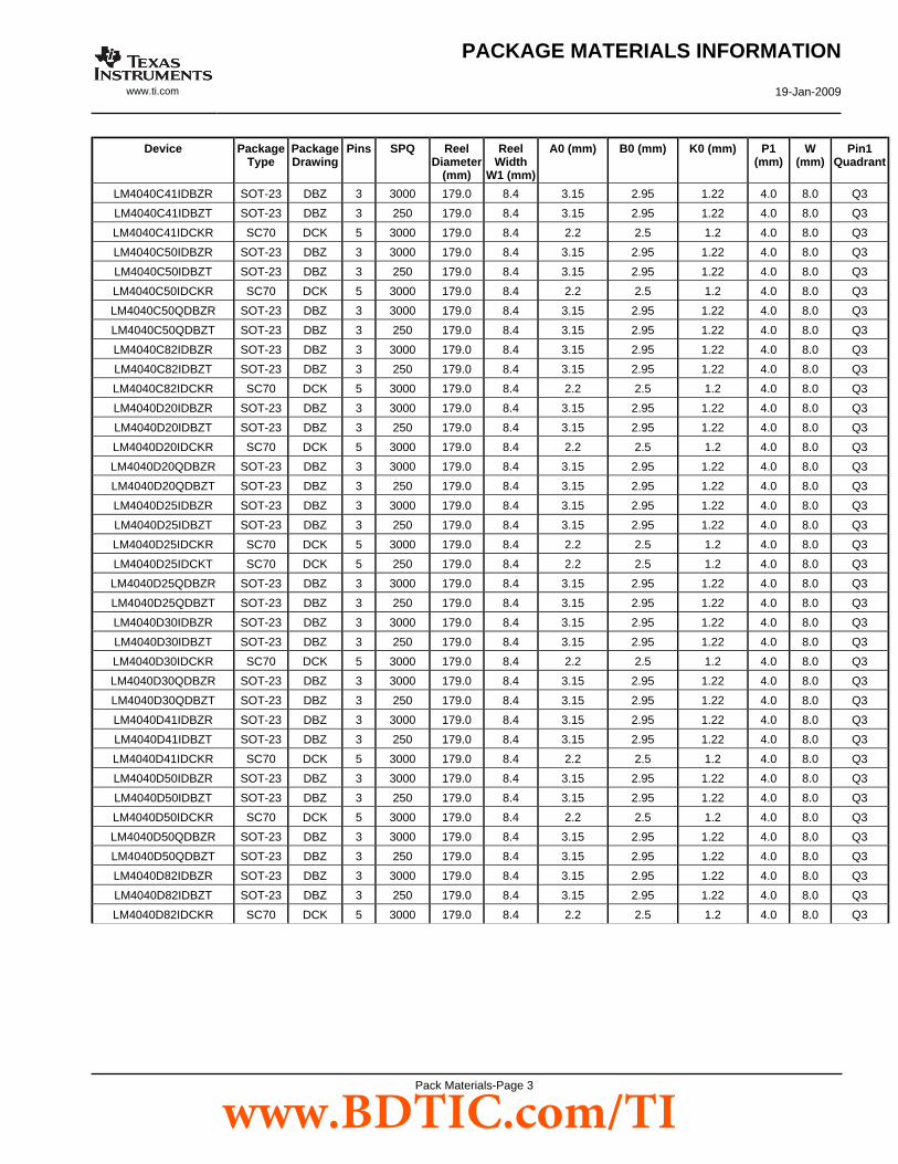
Device PackageType
PackageDrawing
Pins SPQ ReelDiameter
(mm)
ReelWidth
W1 (mm)
A0 (mm) B0 (mm) K0 (mm) P1(mm)
W(mm)
Pin1Quadrant
LM4040C41IDBZR SOT-23 DBZ 3 3000 179.0 8.4 3.15 2.95 1.22 4.0 8.0 Q3
LM4040C41IDBZT SOT-23 DBZ 3 250 179.0 8.4 3.15 2.95 1.22 4.0 8.0 Q3
LM4040C41IDCKR SC70 DCK 5 3000 179.0 8.4 2.2 2.5 1.2 4.0 8.0 Q3
LM4040C50IDBZR SOT-23 DBZ 3 3000 179.0 8.4 3.15 2.95 1.22 4.0 8.0 Q3
LM4040C50IDBZT SOT-23 DBZ 3 250 179.0 8.4 3.15 2.95 1.22 4.0 8.0 Q3
LM4040C50IDCKR SC70 DCK 5 3000 179.0 8.4 2.2 2.5 1.2 4.0 8.0 Q3
LM4040C50QDBZR SOT-23 DBZ 3 3000 179.0 8.4 3.15 2.95 1.22 4.0 8.0 Q3
LM4040C50QDBZT SOT-23 DBZ 3 250 179.0 8.4 3.15 2.95 1.22 4.0 8.0 Q3
LM4040C82IDBZR SOT-23 DBZ 3 3000 179.0 8.4 3.15 2.95 1.22 4.0 8.0 Q3
LM4040C82IDBZT SOT-23 DBZ 3 250 179.0 8.4 3.15 2.95 1.22 4.0 8.0 Q3
LM4040C82IDCKR SC70 DCK 5 3000 179.0 8.4 2.2 2.5 1.2 4.0 8.0 Q3
LM4040D20IDBZR SOT-23 DBZ 3 3000 179.0 8.4 3.15 2.95 1.22 4.0 8.0 Q3
LM4040D20IDBZT SOT-23 DBZ 3 250 179.0 8.4 3.15 2.95 1.22 4.0 8.0 Q3
LM4040D20IDCKR SC70 DCK 5 3000 179.0 8.4 2.2 2.5 1.2 4.0 8.0 Q3
LM4040D20QDBZR SOT-23 DBZ 3 3000 179.0 8.4 3.15 2.95 1.22 4.0 8.0 Q3
LM4040D20QDBZT SOT-23 DBZ 3 250 179.0 8.4 3.15 2.95 1.22 4.0 8.0 Q3
LM4040D25IDBZR SOT-23 DBZ 3 3000 179.0 8.4 3.15 2.95 1.22 4.0 8.0 Q3
LM4040D25IDBZT SOT-23 DBZ 3 250 179.0 8.4 3.15 2.95 1.22 4.0 8.0 Q3
LM4040D25IDCKR SC70 DCK 5 3000 179.0 8.4 2.2 2.5 1.2 4.0 8.0 Q3
LM4040D25IDCKT SC70 DCK 5 250 179.0 8.4 2.2 2.5 1.2 4.0 8.0 Q3
LM4040D25QDBZR SOT-23 DBZ 3 3000 179.0 8.4 3.15 2.95 1.22 4.0 8.0 Q3
LM4040D25QDBZT SOT-23 DBZ 3 250 179.0 8.4 3.15 2.95 1.22 4.0 8.0 Q3
LM4040D30IDBZR SOT-23 DBZ 3 3000 179.0 8.4 3.15 2.95 1.22 4.0 8.0 Q3
LM4040D30IDBZT SOT-23 DBZ 3 250 179.0 8.4 3.15 2.95 1.22 4.0 8.0 Q3
LM4040D30IDCKR SC70 DCK 5 3000 179.0 8.4 2.2 2.5 1.2 4.0 8.0 Q3
LM4040D30QDBZR SOT-23 DBZ 3 3000 179.0 8.4 3.15 2.95 1.22 4.0 8.0 Q3
LM4040D30QDBZT SOT-23 DBZ 3 250 179.0 8.4 3.15 2.95 1.22 4.0 8.0 Q3
LM4040D41IDBZR SOT-23 DBZ 3 3000 179.0 8.4 3.15 2.95 1.22 4.0 8.0 Q3
LM4040D41IDBZT SOT-23 DBZ 3 250 179.0 8.4 3.15 2.95 1.22 4.0 8.0 Q3
LM4040D41IDCKR SC70 DCK 5 3000 179.0 8.4 2.2 2.5 1.2 4.0 8.0 Q3
LM4040D50IDBZR SOT-23 DBZ 3 3000 179.0 8.4 3.15 2.95 1.22 4.0 8.0 Q3
LM4040D50IDBZT SOT-23 DBZ 3 250 179.0 8.4 3.15 2.95 1.22 4.0 8.0 Q3
LM4040D50IDCKR SC70 DCK 5 3000 179.0 8.4 2.2 2.5 1.2 4.0 8.0 Q3
LM4040D50QDBZR SOT-23 DBZ 3 3000 179.0 8.4 3.15 2.95 1.22 4.0 8.0 Q3
LM4040D50QDBZT SOT-23 DBZ 3 250 179.0 8.4 3.15 2.95 1.22 4.0 8.0 Q3
LM4040D82IDBZR SOT-23 DBZ 3 3000 179.0 8.4 3.15 2.95 1.22 4.0 8.0 Q3
LM4040D82IDBZT SOT-23 DBZ 3 250 179.0 8.4 3.15 2.95 1.22 4.0 8.0 Q3
LM4040D82IDCKR SC70 DCK 5 3000 179.0 8.4 2.2 2.5 1.2 4.0 8.0 Q3
PACKAGE MATERIALS INFORMATION
www.ti.com 19-Jan-2009
Pack Materials-Page 3
www.BDTIC.com/TI
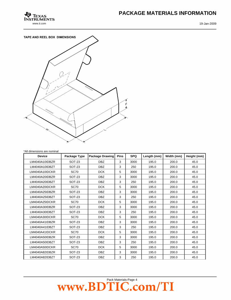
*All dimensions are nominal
Device Package Type Package Drawing Pins SPQ Length (mm) Width (mm) Height (mm)
LM4040A10IDBZR SOT-23 DBZ 3 3000 195.0 200.0 45.0
LM4040A10IDBZT SOT-23 DBZ 3 250 195.0 200.0 45.0
LM4040A10IDCKR SC70 DCK 5 3000 195.0 200.0 45.0
LM4040A20IDBZR SOT-23 DBZ 3 3000 195.0 200.0 45.0
LM4040A20IDBZT SOT-23 DBZ 3 250 195.0 200.0 45.0
LM4040A20IDCKR SC70 DCK 5 3000 195.0 200.0 45.0
LM4040A25IDBZR SOT-23 DBZ 3 3000 195.0 200.0 45.0
LM4040A25IDBZT SOT-23 DBZ 3 250 195.0 200.0 45.0
LM4040A25IDCKR SC70 DCK 5 3000 195.0 200.0 45.0
LM4040A30IDBZR SOT-23 DBZ 3 3000 195.0 200.0 45.0
LM4040A30IDBZT SOT-23 DBZ 3 250 195.0 200.0 45.0
LM4040A30IDCKR SC70 DCK 5 3000 195.0 200.0 45.0
LM4040A41IDBZR SOT-23 DBZ 3 3000 195.0 200.0 45.0
LM4040A41IDBZT SOT-23 DBZ 3 250 195.0 200.0 45.0
LM4040A41IDCKR SC70 DCK 5 3000 195.0 200.0 45.0
LM4040A50IDBZR SOT-23 DBZ 3 3000 195.0 200.0 45.0
LM4040A50IDBZT SOT-23 DBZ 3 250 195.0 200.0 45.0
LM4040A50IDCKR SC70 DCK 5 3000 195.0 200.0 45.0
LM4040A82IDBZR SOT-23 DBZ 3 3000 195.0 200.0 45.0
LM4040A82IDBZT SOT-23 DBZ 3 250 195.0 200.0 45.0
PACKAGE MATERIALS INFORMATION
www.ti.com 19-Jan-2009
Pack Materials-Page 4
www.BDTIC.com/TI
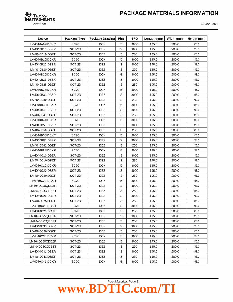
Device Package Type Package Drawing Pins SPQ Length (mm) Width (mm) Height (mm)
LM4040A82IDCKR SC70 DCK 5 3000 195.0 200.0 45.0
LM4040B10IDBZR SOT-23 DBZ 3 3000 195.0 200.0 45.0
LM4040B10IDBZT SOT-23 DBZ 3 250 195.0 200.0 45.0
LM4040B10IDCKR SC70 DCK 5 3000 195.0 200.0 45.0
LM4040B20IDBZR SOT-23 DBZ 3 3000 195.0 200.0 45.0
LM4040B20IDBZT SOT-23 DBZ 3 250 195.0 200.0 45.0
LM4040B20IDCKR SC70 DCK 5 3000 195.0 200.0 45.0
LM4040B25IDBZR SOT-23 DBZ 3 3000 195.0 200.0 45.0
LM4040B25IDBZT SOT-23 DBZ 3 250 195.0 200.0 45.0
LM4040B25IDCKR SC70 DCK 5 3000 195.0 200.0 45.0
LM4040B30IDBZR SOT-23 DBZ 3 3000 195.0 200.0 45.0
LM4040B30IDBZT SOT-23 DBZ 3 250 195.0 200.0 45.0
LM4040B30IDCKR SC70 DCK 5 3000 195.0 200.0 45.0
LM4040B41IDBZR SOT-23 DBZ 3 3000 195.0 200.0 45.0
LM4040B41IDBZT SOT-23 DBZ 3 250 195.0 200.0 45.0
LM4040B41IDCKR SC70 DCK 5 3000 195.0 200.0 45.0
LM4040B50IDBZR SOT-23 DBZ 3 3000 195.0 200.0 45.0
LM4040B50IDBZT SOT-23 DBZ 3 250 195.0 200.0 45.0
LM4040B50IDCKR SC70 DCK 5 3000 195.0 200.0 45.0
LM4040B82IDBZR SOT-23 DBZ 3 3000 195.0 200.0 45.0
LM4040B82IDBZT SOT-23 DBZ 3 250 195.0 200.0 45.0
LM4040B82IDCKR SC70 DCK 5 3000 195.0 200.0 45.0
LM4040C10IDBZR SOT-23 DBZ 3 3000 195.0 200.0 45.0
LM4040C10IDBZT SOT-23 DBZ 3 250 195.0 200.0 45.0
LM4040C10IDCKR SC70 DCK 5 3000 195.0 200.0 45.0
LM4040C20IDBZR SOT-23 DBZ 3 3000 195.0 200.0 45.0
LM4040C20IDBZT SOT-23 DBZ 3 250 195.0 200.0 45.0
LM4040C20IDCKR SC70 DCK 5 3000 195.0 200.0 45.0
LM4040C20QDBZR SOT-23 DBZ 3 3000 195.0 200.0 45.0
LM4040C20QDBZT SOT-23 DBZ 3 250 195.0 200.0 45.0
LM4040C25IDBZR SOT-23 DBZ 3 3000 195.0 200.0 45.0
LM4040C25IDBZT SOT-23 DBZ 3 250 195.0 200.0 45.0
LM4040C25IDCKR SC70 DCK 5 3000 195.0 200.0 45.0
LM4040C25IDCKT SC70 DCK 5 250 195.0 200.0 45.0
LM4040C25QDBZR SOT-23 DBZ 3 3000 195.0 200.0 45.0
LM4040C25QDBZT SOT-23 DBZ 3 250 195.0 200.0 45.0
LM4040C30IDBZR SOT-23 DBZ 3 3000 195.0 200.0 45.0
LM4040C30IDBZT SOT-23 DBZ 3 250 195.0 200.0 45.0
LM4040C30IDCKR SC70 DCK 5 3000 195.0 200.0 45.0
LM4040C30QDBZR SOT-23 DBZ 3 3000 195.0 200.0 45.0
LM4040C30QDBZT SOT-23 DBZ 3 250 195.0 200.0 45.0
LM4040C41IDBZR SOT-23 DBZ 3 3000 195.0 200.0 45.0
LM4040C41IDBZT SOT-23 DBZ 3 250 195.0 200.0 45.0
LM4040C41IDCKR SC70 DCK 5 3000 195.0 200.0 45.0
PACKAGE MATERIALS INFORMATION
www.ti.com 19-Jan-2009
Pack Materials-Page 5
www.BDTIC.com/TI

Device Package Type Package Drawing Pins SPQ Length (mm) Width (mm) Height (mm)
LM4040C50IDBZR SOT-23 DBZ 3 3000 195.0 200.0 45.0
LM4040C50IDBZT SOT-23 DBZ 3 250 195.0 200.0 45.0
LM4040C50IDCKR SC70 DCK 5 3000 195.0 200.0 45.0
LM4040C50QDBZR SOT-23 DBZ 3 3000 195.0 200.0 45.0
LM4040C50QDBZT SOT-23 DBZ 3 250 195.0 200.0 45.0
LM4040C82IDBZR SOT-23 DBZ 3 3000 195.0 200.0 45.0
LM4040C82IDBZT SOT-23 DBZ 3 250 195.0 200.0 45.0
LM4040C82IDCKR SC70 DCK 5 3000 195.0 200.0 45.0
LM4040D20IDBZR SOT-23 DBZ 3 3000 195.0 200.0 45.0
LM4040D20IDBZT SOT-23 DBZ 3 250 195.0 200.0 45.0
LM4040D20IDCKR SC70 DCK 5 3000 195.0 200.0 45.0
LM4040D20QDBZR SOT-23 DBZ 3 3000 195.0 200.0 45.0
LM4040D20QDBZT SOT-23 DBZ 3 250 195.0 200.0 45.0
LM4040D25IDBZR SOT-23 DBZ 3 3000 195.0 200.0 45.0
LM4040D25IDBZT SOT-23 DBZ 3 250 195.0 200.0 45.0
LM4040D25IDCKR SC70 DCK 5 3000 195.0 200.0 45.0
LM4040D25IDCKT SC70 DCK 5 250 195.0 200.0 45.0
LM4040D25QDBZR SOT-23 DBZ 3 3000 195.0 200.0 45.0
LM4040D25QDBZT SOT-23 DBZ 3 250 195.0 200.0 45.0
LM4040D30IDBZR SOT-23 DBZ 3 3000 195.0 200.0 45.0
LM4040D30IDBZT SOT-23 DBZ 3 250 195.0 200.0 45.0
LM4040D30IDCKR SC70 DCK 5 3000 195.0 200.0 45.0
LM4040D30QDBZR SOT-23 DBZ 3 3000 195.0 200.0 45.0
LM4040D30QDBZT SOT-23 DBZ 3 250 195.0 200.0 45.0
LM4040D41IDBZR SOT-23 DBZ 3 3000 195.0 200.0 45.0
LM4040D41IDBZT SOT-23 DBZ 3 250 195.0 200.0 45.0
LM4040D41IDCKR SC70 DCK 5 3000 195.0 200.0 45.0
LM4040D50IDBZR SOT-23 DBZ 3 3000 195.0 200.0 45.0
LM4040D50IDBZT SOT-23 DBZ 3 250 195.0 200.0 45.0
LM4040D50IDCKR SC70 DCK 5 3000 195.0 200.0 45.0
LM4040D50QDBZR SOT-23 DBZ 3 3000 195.0 200.0 45.0
LM4040D50QDBZT SOT-23 DBZ 3 250 195.0 200.0 45.0
LM4040D82IDBZR SOT-23 DBZ 3 3000 195.0 200.0 45.0
LM4040D82IDBZT SOT-23 DBZ 3 250 195.0 200.0 45.0
LM4040D82IDCKR SC70 DCK 5 3000 195.0 200.0 45.0
PACKAGE MATERIALS INFORMATION
www.ti.com 19-Jan-2009
Pack Materials-Page 6
www.BDTIC.com/TI
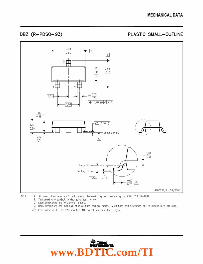
www.BDTIC.com/TI
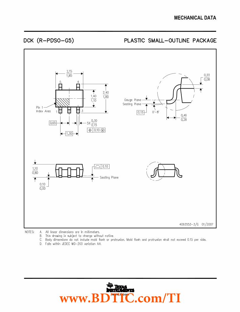
www.BDTIC.com/TI
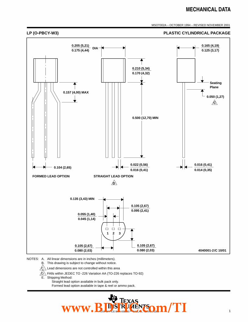
MECHANICAL DATA
MSOT002A – OCTOBER 1994 – REVISED NOVEMBER 2001
1POST OFFICE BOX 655303 • DALLAS, TEXAS 75265
LP (O-PBCY-W3) PLASTIC CYLINDRICAL PACKAGE
4040001-2/C 10/01
STRAIGHT LEAD OPTION
0.016 (0,41)
0.014 (0,35)
0.157 (4,00) MAX
FORMED LEAD OPTION
0.104 (2,65)
0.210 (5,34)0.170 (4,32)
0.050 (1,27)
0.016 (0,41)
0.022 (0,56)
0.500 (12,70) MIN
SeatingPlane
0.175 (4,44)0.205 (5,21) 0.165 (4,19)
0.125 (3,17)DIA
D
C
0.105 (2,67)0.095 (2,41)
0.135 (3,43) MIN
0.080 (2,03)
0.055 (1,40)0.045 (1,14)
1
0.105 (2,67)
2 3
0.080 (2,03)0.105 (2,67)
NOTES: A. All linear dimensions are in inches (millimeters).B. This drawing is subject to change without notice.
C. Lead dimensions are not controlled within this area
D. FAlls within JEDEC TO -226 Variation AA (TO-226 replaces TO-92)E. Shipping Method:
Straight lead option available in bulk pack only.Formed lead option available in tape & reel or ammo pack.
www.BDTIC.com/TI
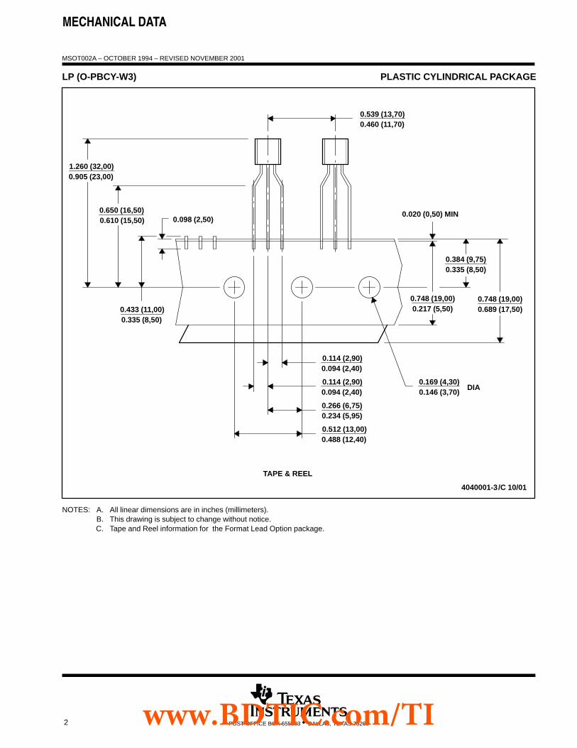
MECHANICAL DATA
MSOT002A – OCTOBER 1994 – REVISED NOVEMBER 2001
2 POST OFFICE BOX 655303 • DALLAS, TEXAS 75265
LP (O-PBCY-W3) PLASTIC CYLINDRICAL PACKAGE
4040001-3/C 10/01
0.094 (2,40)0.114 (2,90)
0.460 (11,70)0.539 (13,70)
TAPE & REEL
0.335 (8,50)0.384 (9,75)
0.020 (0,50) MIN
0.217 (5,50)0.748 (19,00) 0.748 (19,00)
0.689 (17,50)
0.098 (2,50)
0.433 (11,00)0.335 (8,50)
0.610 (15,50)0.650 (16,50)
1.260 (32,00)0.905 (23,00)
0.234 (5,95)0.266 (6,75)
0.512 (13,00)0.488 (12,40)
0.114 (2,90)0.094 (2,40) 0.146 (3,70)
0.169 (4,30)DIA
NOTES: A. All linear dimensions are in inches (millimeters).B. This drawing is subject to change without notice.C. Tape and Reel information for the Format Lead Option package.
www.BDTIC.com/TI
IMPORTANT NOTICETexas Instruments Incorporated and its subsidiaries (TI) reserve the right to make corrections, modifications, enhancements, improvements,and other changes to its products and services at any time and to discontinue any product or service without notice. Customers shouldobtain the latest relevant information before placing orders and should verify that such information is current and complete. All products aresold subject to TI’s terms and conditions of sale supplied at the time of order acknowledgment.TI warrants performance of its hardware products to the specifications applicable at the time of sale in accordance with TI’s standardwarranty. Testing and other quality control techniques are used to the extent TI deems necessary to support this warranty. Except wheremandated by government requirements, testing of all parameters of each product is not necessarily performed.TI assumes no liability for applications assistance or customer product design. Customers are responsible for their products andapplications using TI components. To minimize the risks associated with customer products and applications, customers should provideadequate design and operating safeguards.TI does not warrant or represent that any license, either express or implied, is granted under any TI patent right, copyright, mask work right,or other TI intellectual property right relating to any combination, machine, or process in which TI products or services are used. Informationpublished by TI regarding third-party products or services does not constitute a license from TI to use such products or services or awarranty or endorsement thereof. Use of such information may require a license from a third party under the patents or other intellectualproperty of the third party, or a license from TI under the patents or other intellectual property of TI.Reproduction of TI information in TI data books or data sheets is permissible only if reproduction is without alteration and is accompaniedby all associated warranties, conditions, limitations, and notices. Reproduction of this information with alteration is an unfair and deceptivebusiness practice. TI is not responsible or liable for such altered documentation. Information of third parties may be subject to additionalrestrictions.Resale of TI products or services with statements different from or beyond the parameters stated by TI for that product or service voids allexpress and any implied warranties for the associated TI product or service and is an unfair and deceptive business practice. TI is notresponsible or liable for any such statements.TI products are not authorized for use in safety-critical applications (such as life support) where a failure of the TI product would reasonablybe expected to cause severe personal injury or death, unless officers of the parties have executed an agreement specifically governingsuch use. Buyers represent that they have all necessary expertise in the safety and regulatory ramifications of their applications, andacknowledge and agree that they are solely responsible for all legal, regulatory and safety-related requirements concerning their productsand any use of TI products in such safety-critical applications, notwithstanding any applications-related information or support that may beprovided by TI. Further, Buyers must fully indemnify TI and its representatives against any damages arising out of the use of TI products insuch safety-critical applications.TI products are neither designed nor intended for use in military/aerospace applications or environments unless the TI products arespecifically designated by TI as military-grade or "enhanced plastic." Only products designated by TI as military-grade meet militaryspecifications. Buyers acknowledge and agree that any such use of TI products which TI has not designated as military-grade is solely atthe Buyer's risk, and that they are solely responsible for compliance with all legal and regulatory requirements in connection with such use.TI products are neither designed nor intended for use in automotive applications or environments unless the specific TI products aredesignated by TI as compliant with ISO/TS 16949 requirements. Buyers acknowledge and agree that, if they use any non-designatedproducts in automotive applications, TI will not be responsible for any failure to meet such requirements.Following are URLs where you can obtain information on other Texas Instruments products and application solutions:Products ApplicationsAmplifiers amplifier.ti.com Audio www.ti.com/audioData Converters dataconverter.ti.com Automotive www.ti.com/automotiveDLP® Products www.dlp.com Broadband www.ti.com/broadbandDSP dsp.ti.com Digital Control www.ti.com/digitalcontrolClocks and Timers www.ti.com/clocks Medical www.ti.com/medicalInterface interface.ti.com Military www.ti.com/militaryLogic logic.ti.com Optical Networking www.ti.com/opticalnetworkPower Mgmt power.ti.com Security www.ti.com/securityMicrocontrollers microcontroller.ti.com Telephony www.ti.com/telephonyRFID www.ti-rfid.com Video & Imaging www.ti.com/videoRF/IF and ZigBee® Solutions www.ti.com/lprf Wireless www.ti.com/wireless
Mailing Address: Texas Instruments, Post Office Box 655303, Dallas, Texas 75265Copyright © 2009, Texas Instruments Incorporated
www.BDTIC.com/TI