Embed Size (px)
Citation preview
Precision Spray Nozzlesand Accessories
As the business world becomes more competitive by the day, you have to work constantly to improve product quality, build your own efficiency and cut costs. That is the only way to keep your customers and grow your business.
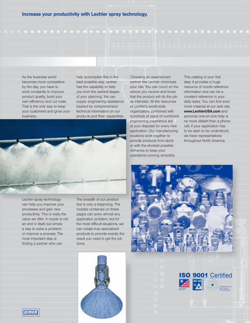
Lechler spray technology can help you improve your processes and gain new productivity. This is really the value we offer. A nozzle is not an end in itself, but simply a way to solve a problem or improve a process. The most important step is finding a partner who can
help accomplish this in the best possible way. Lechler has the capability to help you from the earliest stages of your planning. We can supply engineering assistance backed by comprehensive technical information on our products and their capabilities.
The breadth of our product line is only a beginning. The nozzles contained on these pages can solve almost any application problem, but for the most difficult situations, we can create truly specialized products to provide exactly the result you need to get the job done.
Choosing an experienced partner like Lechler minimizes your risk. You can count on the advice you receive and know that the product will do the job as intended. All the resources of Lechler's world-wide organization, combined with hundreds of years of combined engineering experience are at your disposal for every new application. Our manufacturing locations work together to provide products from stock or with the shortest possible deliveries to keep your operations running smoothly.
This catalog is your first step. It provides a huge resource of nozzle reference information and can be a constant reference in your daily tasks. You can find even more material at our web site, www.LechlerUSA.com and personal one-on-one help is no more distant than a phone call. If your application has to be seen to be understood, we have representatives throughout North America.
Increase your productivity with Lechler spray technology.
Table of contents: Page:
Introduction
Air atomizing nozzles 17
Hollow cone nozzles 31
Full cone nozzles 37
Flat fan nozzles 49
Air nozzles 73
Tank cleaning nozzles 77
Accessories 95
Nozzle Headers 104
Pulp and paper 107
For nozzle assembly and
special brochures, please
refer to the final pages of
the catalog.
1
2
Each spray application has its own set of expectations.
A properly configured spray application can fulfill any number of functions in a way that is both efficient and cost effective. Creating that configuration requires intimate knowledge of nozzle products and how they are best applied to achieve a specific outcome. If done in a haphazard manner, there can be many undesirable side effects that waste product, energy and time.
To keep new applications from becoming costly experiments, Lechler has formed special teams to develop expertise in wide variety of industries. The assistance of outside consultants combined with the accumulated know-how of dozens of application engineers world-wide has helped us compile practical knowledge that is at your fingertips any time you bring one of your applications to us.
From the concept phase of a new project to the final delivery, Lechler can help guide your decisions so the ultimate solution is both technically and economically sound.
At the end of the catalog, you’ll find a listing of our literature showing our products for specific industries and applications. Moreover, our web sites contain a wide variety of literature, articles and helpful information on more specialized situations.
Here are examples of specific industries and applications where Lechler has built specific expertise and can offer much helpful information:
Chemical processingGas conditioning, reactors, scrubbers, mist eliminators, tank cleaning, fermenters, condensers
SteelmakingDescaling, caster cooling, roll cooling, differential cooling shape control, strip coating
Environmental technologyScrubbers, gas cooling, FGD, NOx abatement, dust suppression
Pulp and paperOscillating showers, felt and wire cleaning, trimming nozzles, stationary showers, filter cleaning
Food and beverageProduce washing, tank cleaning, fermenters, humidification, CIP systems
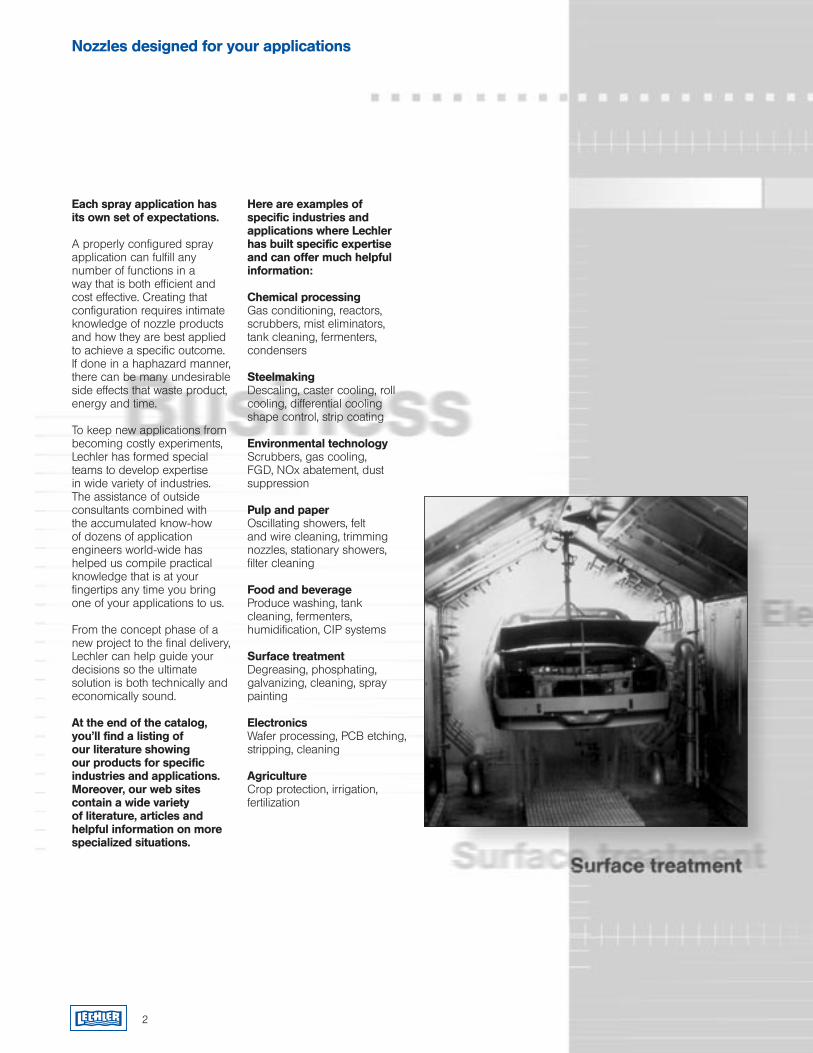
Surface treatmentDegreasing, phosphating, galvanizing, cleaning, spray painting
ElectronicsWafer processing, PCB etching, stripping, cleaning
AgricultureCrop protection, irrigation, fertilization
Nozzles designed for your applications

3
4
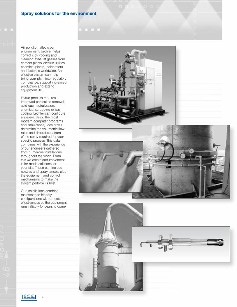
Air pollution affects our environment. Lechler helps control it by cooling and cleaning exhaust gasses from cement plants, electric utilities, chemical plants, incinerators and factories worldwide. An effective system can help bring your plant into regulatory compliance, support increased production and extend equipment life.
If your process requires improved particulate removal, acid gas neutralization, chemical scrubbing or gas cooling, Lechler can configure a system. Using the most modern computer programs and simulations, Lechler will determine the volumetric flow rates and droplet spectrum of the spray required for your specific process. This data combines with the experience of our engineers gathered from numerous installations throughout the world. From this we create and implement tailor made solutions for your site. These can include nozzles and spray lances, plus the equipment and control mechanisms to make the system perform its best.
Our installations combine maintenance friendly configurations with process effectiveness so the equipment runs reliably for years to come.
Spray solutions for the environment
Liquid characteristics and nozzle performance
The characteristics of the liq-uid being sprayed, combined with the operating conditions have a major effect on the nozzle performance.
PressureThe greatest influence on the flow rate is pressure. Normally, the flow changes in correlation with the square root of the pressure. This relationship is very direct with most designs, although there are exceptions (including axial full cones and some tank cleaning nozzles). Some pages indicate an alternate formula, but most of the time this one applies:
Q2 = Q1
Q1 and P1 are the known flow rate and pressure.
Q2 is resulting flow rate for the desired pressure P2.
If you need to calculate the pressure to achieve a specific flow rate, you can use a variation of the same formula:
P2 = P1
P1 and Q1 are the known pressure and flow rate.
P2 is the resulting pressure for the desired flow rate Q2.
TemperatureTemperature influences a liquid’s viscosity, surface tension, and specific gravity, which in turn can affect spray nozzle performance.
ViscosityViscosity is probably the most significant of all liquid properties because it can vary over an extreme range. Liquid viscosity resists surface formation. If the viscosity is great enough, a nozzle may produce a mass of filaments instead of a spray. Liquid viscosity is remarkably sensitive to temperature. Thus, liquid viscosity has a significant effect on all of the spray characteristics.
Specific gravityThe main effect of the specific gravity of a fluid being sprayed is on the flow rate of the nozzle. The lower the specific gravity of a liquid, the higher the velocity through the nozzle, and vice versa. Thus, for lower specific gravity, the flow rate is larger than for liquid with a higher specific gravity at the same pressure.
(Flow rate of water) x
For example, for a specific gravity of 1.2:
4 gpm = 3.6 gpmWater Liquid
Surface tensionSurface tension is an important physical property affecting surface formation, and makes the liquid resist breaking into droplets. The main effect of surface tension is on the spray angle and droplet size of the spray nozzle as well as the spray distribution.
Nozzle wearNozzle wear is denoted by an increased nozzle flow capacity and the subsequent deterioration of spray performance. A reduction in system operating pressure is often an indication of increased nozzle wear, especially when positive displacement pumps are used. Flat fan axial nozzles exhibit a narrowing of the spray pattern with wear. Other type spray nozzles reveal a loss in distribution uniformity within the spray pattern — though without a noticeable change in pattern size.
( Q2
Q1)
2
1
Sp. Gravity of liquid
x
1
1.20
√ P2
P1
Carbide
Ceramics
Silicon Carbide(Nitride Bonded)
Stellite
Hardened Stainless Steel
Hastelloys
Stainless Steel
Steel
Brass
Aluminum
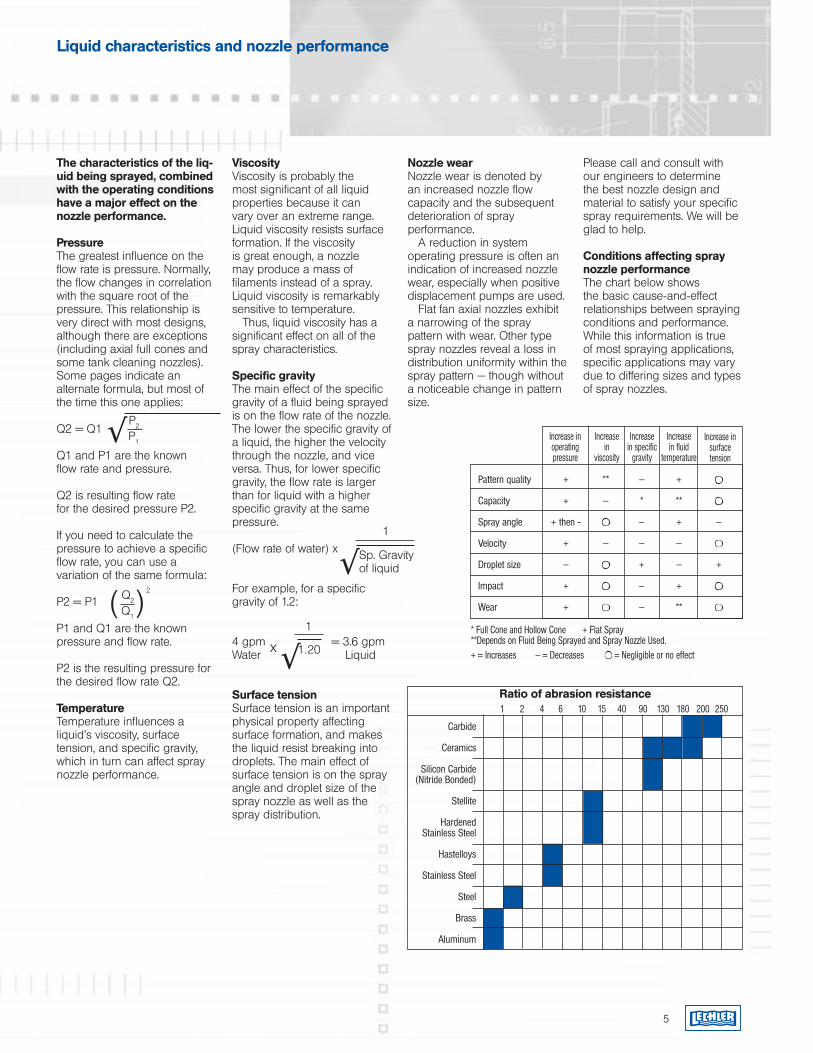
Ratio of abrasion resistance 1 2 4 6 10 15 40 90 130 180 200 250
Please call and consult with our engineers to determine the best nozzle design and material to satisfy your specific spray requirements. We will be glad to help.
Conditions affecting spray nozzle performanceThe chart below shows the basic cause-and-effect relationships between spraying conditions and performance. While this information is true of most spraying applications, specific applications may vary due to differing sizes and types of spray nozzles.
Increase in operating pressure
Increase in
viscosity
Increase in specific
gravity
Increase in fluid
temperature
Increase in surface tension
* Full Cone and Hollow Cone + Flat Spray **Depends on Fluid Being Sprayed and Spray Nozzle Used.+ = Increases — = Decreases = Negligible or no effect
√
Pattern quality + ** — +
Capacity + — * **
Spray angle + then - — + —
Velocity + — — —
Droplet size — + — +
Impact + — +
Wear + — **
√
5
Using the rules of spray technology to your advantage
The process of breaking a mass of liquid into individual droplets is called atomization. The ultimate purpose of this is two fold: Control the distribution of the liquid over a surface or through space, or, increase the amount of liquid surface area available. Whatever the desired outcome, all applications rely on the basic principles of atomization.
Single fluid atomization
Forcing liquid under pressure through a specifically shaped chamber and orifice can increase its velocity in such a way that when it is released, it breaks into waves that break into individual droplets. The artistry of this process is creating precisely the right geometry to give the liquid the desired shape and distribution when it leaves the nozzle. This employs a careful combination of internal liquid collision, turbulence and spinning action.
Air (twin fluid) atomization
Moving gas streams mixing with liquid can also create the necessary waves to generate liquid droplets. Since such a gas stream can have very high velocities, a great deal of energy can be transferred to the liquid, which can result in exceptionally small droplets. Additionally, this method allows atomization of liquids that have too high a viscosity for conventional single fluid nozzles.
Pneumatic atomizers employ two main design approaches: Internal and external mix. With internal mix, the liquid and gas are mixed inside the nozzle and exit together through a final orifice. External mix
6
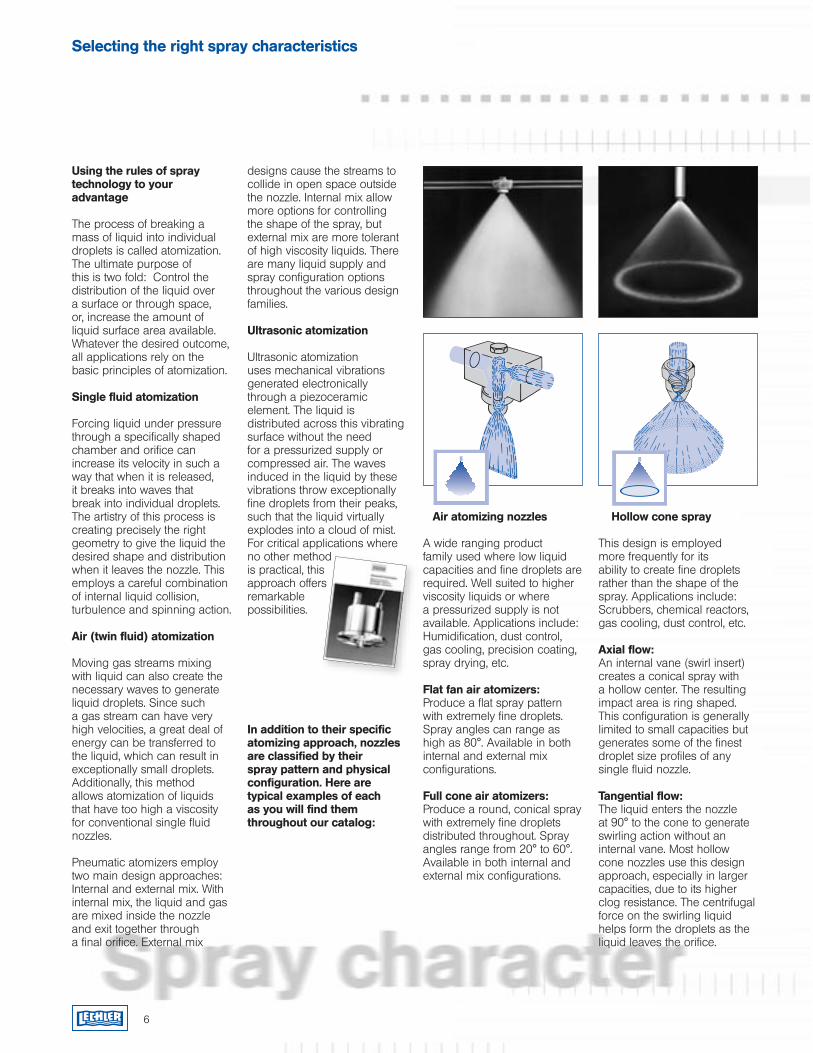
Air atomizing nozzles
A wide ranging product family used where low liquid capacities and fine droplets are required. Well suited to higher viscosity liquids or where a pressurized supply is not available. Applications include: Humidification, dust control, gas cooling, precision coating, spray drying, etc.
Flat fan air atomizers: Produce a flat spray pattern with extremely fine droplets. Spray angles can range as high as 80°. Available in both internal and external mix configurations.
Full cone air atomizers: Produce a round, conical spray with extremely fine droplets distributed throughout. Spray angles range from 20° to 60°. Available in both internal and external mix configurations.
Hollow cone spray
This design is employed more frequently for its ability to create fine droplets rather than the shape of the spray. Applications include: Scrubbers, chemical reactors, gas cooling, dust control, etc.
Axial flow: An internal vane (swirl insert) creates a conical spray with a hollow center. The resulting impact area is ring shaped. This configuration is generally limited to small capacities but generates some of the finest droplet size profiles of any single fluid nozzle.
Tangential flow: The liquid enters the nozzle at 90° to the cone to generate swirling action without an internal vane. Most hollow cone nozzles use this design approach, especially in larger capacities, due to its higher clog resistance. The centrifugal force on the swirling liquid helps form the droplets as the liquid leaves the orifice.
Selecting the right spray characteristics
designs cause the streams to collide in open space outside the nozzle. Internal mix allow more options for controlling the shape of the spray, but external mix are more tolerant of high viscosity liquids. There are many liquid supply and spray configuration options throughout the various design families.
Ultrasonic atomization
Ultrasonic atomization uses mechanical vibrations generated electronically through a piezoceramic element. The liquid is distributed across this vibrating surface without the need for a pressurized supply or compressed air. The waves induced in the liquid by these vibrations throw exceptionally fine droplets from their peaks, such that the liquid virtually explodes into a cloud of mist. For critical applications where no other method is practical, this approach offers remarkable possibilities.
In addition to their specific atomizing approach, nozzles are classified by their spray pattern and physical configuration. Here are typical examples of each as you will find them throughout our catalog:
7
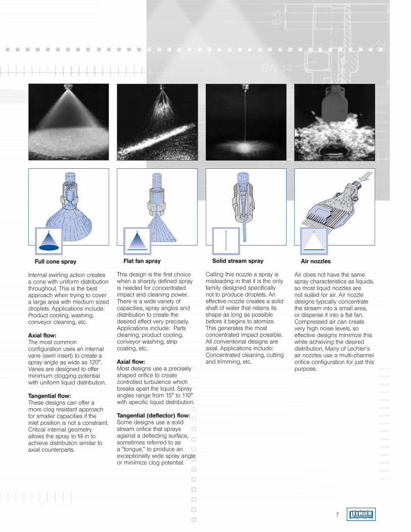
Full cone spray
Internal swirling action creates a cone with uniform distribution throughout. This is the best approach when trying to cover a large area with medium sized droplets. Applications include: Product cooling, washing, conveyor cleaning, etc.
Axial flow: The most common configuration uses an internal vane (swirl insert) to create a spray angle as wide as 120°. Vanes are designed to offer minimum clogging potential with uniform liquid distribution.
Tangential flow: These designs can offer a more clog resistant approach for smaller capacities if the inlet position is not a constraint. Critical internal geometry allows the spray to fill in to achieve distribution similar to axial counterparts.
Flat fan spray
This design is the first choice when a sharply defined spray is needed for concentrated impact and cleaning power. There is a wide variety of capacities, spray angles and distribution to create the desired effect very precisely. Applications include: Parts cleaning, product cooling, conveyor washing, strip coating, etc.
Axial flow: Most designs use a precisely shaped orifice to create controlled turbulence which breaks apart the liquid. Spray angles range from 15° to 110° with specific liquid distribution.
Tangential (deflector) flow: Some designs use a solid stream orifice that sprays against a deflecting surface, sometimes referred to as a “tongue,” to produce an exceptionally wide spray angle or minimize clog potential.
Solid stream spray
Calling this nozzle a spray is misleading in that it is the only family designed specifically not to produce droplets. An effective nozzle creates a solid shaft of water that retains its shape as long as possible before it begins to atomize. This generates the most concentrated impact possible. All conventional designs are axial. Applications include: Concentrated cleaning, cutting and trimming, etc.
Air nozzles
Air does not have the same spray characteristics as liquids, so most liquid nozzles are not suited for air. Air nozzle designs typically concentrate the stream into a small area, or disperse it into a flat fan. Compressed air can create very high noise levels, so effective designs minimize this while achieving the desired distribution. Many of Lechler’s air nozzles use a multi-channel orifice configuration for just this purpose.
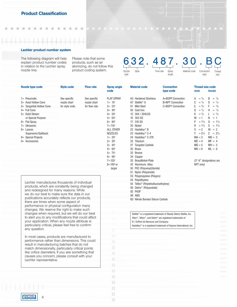
Nozzle type code Style code Flow rate Spray angle Material code Connection Thread size code code type code male female
1= Pneumatic See specific See specific FLAT SPRAY A3 Hardened Stainless A=BSPP Connection A = 1/8 B = 1/8
2= Axial Hollow Cone nozzle chart nozzle chart 1= 15o A7 Stellite® 6 B=NPT Connection C = 1/4 D = 1/4
3= Tangential Hollow Cone for style code. for flow rate. 2= 25o 01 Mild Steel C=BSPT Connection E = 3/8 F = 3/8 4= Full Cone 3= 40o 05 Cast Iron G = 1/2 H = 1/2
5= Solid Stream 4= 50o 1C 304 / 304LSS K = 3/4 L = 3/4
or Special Purpose 5= 65o 16 303 SS M = 1 N = 16= Flat Spray 6= 80o 17 316 SS P = 11/4 Q = 11/4
7= Ultrasonic 7= 110o 20 Nickel R = 11/2 S = 11/2
8= Lances ALL OTHER 22 Hastelloy® B V = 2 W = 2 Supersonic/Spillback NOZZLES 23 Hastelloy® C-4 Y = 21/2 Z = 21/2
9= Special Projects 1= 20o 24 Hastelloy® C-276 MA = 3 MB = 30= Accessories 2= 30o 25 Titanium ME = 4 MF = 4 3= 45o 27 Tungsten Carbide MG = 5 MH = 5 4= 60o 30 Brass MK = 6 ML = 6 5= 75o 32 Bronze 6= 90o 34 Copper 7= 120o 35 BrassNickel-Plate (3"-6" designations are 8=140o or 42 Aluminum, Alloy NPT only) larger 50 PVC (Polyvinylchloride) 51 Nylon (Polyamide) 53 Polypropylene (Polypro) 54 Polyethylene 55 Teflon® (Polytetrafluoroethylene) 56 Delrin® (Polyacetate) 5E PVDF 5K ABS 6D Nitride Bonded Silicon Carbide
The following diagram will help explain product number codes in relation to the Lechler spray nozzle line.
6 3 2 . 4 8 7 . 3 0 . B CPlease note that some products, such as air atomizing, do not follow this product coding system. Nozzle
typeStyle Flow rate Spray
angleMaterial code Connection
typeThread
size
Stellite® is a registered trademark of Stoody Deloro Stellite, Inc.Viton®, Teflon®, and Delrin® are registered trademarks of E.I. DuPont de Nemours and Company.Hastelloy® is a registered trademark of Haynes International, Inc.
Product Classification
8
Lechler product number system
Lechler manufactures thousands of individual products, which are constantly being changed and redesigned for many reasons. While we do our best to make sure the data in our publications accurately reflects our products, there are times when some aspect of performance or physical configuration many changes. We reserve the right to make such changes when required, but we will do our best to alert you to any modifications that could affect your application. When any nozzle attribute is particularly critical, please feel free to confirm any question.
In most cases, products are manufactured to performance rather than dimensions. This could result in manufacturing batches that do not match dimensionally, particularly critical points like orifice diameters. If you see something that causes you concern, please consult with your Lechler representative.
9
Nozzle performance and service data
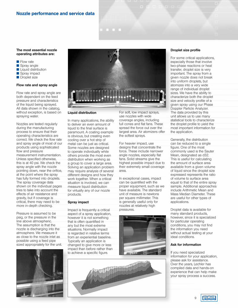
The most essential nozzle operating attributes are:
Flow rate Spray angle Liquid distribution Spray impact Droplet size
Flow rate and spray angle
Flow rate and spray angle are both dependent on the feed pressure and characteristics of the liquid being sprayed. All data shown in the catalog, without exception, is based on spraying water.
Nozzles are tested regularly during the manufacturing process to ensure that their operating characteristics are correct. We check the flow rate and spray angle of most of our products using sophisticated flow and pressure measurement instrumentation. Unless specified otherwise, this is at 40 psi. We check the spray angle with the nozzle pointing down, near the orifice, at the point where the spray has fully formed into droplets. The spray coverage data shown on the individual pages tries to take into account the effects of air resistance and gravity, but if coverage is critical, there may need to be more in-depth checking.
Pressure is assumed to be psig, or the pressure in the line above atmospheric. The assumption is that the nozzle is discharging into the atmosphere. We measure it as close to the nozzle inlet as possible using a feed pipe sized appropriately for the unit.
Liquid distribution
In many applications, the ability to deliver an even amount of liquid to the final surface is paramount. A coating example is obvious, but creating even cooling over a hot strip of metal can be just as critical. Some nozzles are designed to operate individually while others provide the most even distribution when working as a group to cover a large area. Solving an application problem may require analysis of several different designs and how they work together. When a critical situation is involved, we can measure liquid distribution for virtually any of our nozzle products.
Spray impact
Impact is frequently a critical aspect of a spray application, however it is not something that is often quantified in any but the most extreme situations. Normally impact is regarded in relative terms from an experiential baseline. Typically an application is changed to give more or less impact than before rather than to achieve a specific figure.
For soft, low impact sprays, use nozzles with wide coverage angles, including full cones and flat fans. These spread the force out over the largest area. Air atomizers offer the softest sprays.
For heavier impact, use designs that concentrate the force. These include narrower angle nozzles, especially flat fans. Solid streams give the highest possible impact due to their extremely small coverage area.
In exceptional cases, impact can be quantified with the proper equipment, such as we have available. The standard unit of measure is newtons per square millimeter. This is generally useful only for nozzles at relatively high pressures.
Droplet size profile
For some critical applications, especially those that involve two-phase reactions or heat transfer, droplet size is very important. The spray from a given nozzle does not break into uniform droplets, but atomizes into a very wide range of individual droplet sizes. We have the ability to characterize both the droplet size and velocity profile of a given spray using our Phase Doppler Particle Analyzer. The data provided by this unit allows us to use many statistical tools to characterize the droplet profile to yield the most important information for the application.
Generally, the distribution can be reduced to a single figure. One of the most commonly used is the Sauter Mean, designated as d32. This is useful for calculating the amount of surface area available from a given volume of liquid since the droplet size expressed represents the ratio of volume to surface area equal to that of the entire spray sample. Additional approaches include Arithmetic Mean and Mass Median Diameter. These are useful for other types of applications.
Droplet data is available for many standard products, however, since it is specialized for particular operating conditions, you may not find the information you need without actual testing at your ideal conditions.
Ask for information
If you need specialized information for your application, please ask for assistance. Over the years, Lechler has compiled data and hands-on experience that can help make your spray process a success.
10
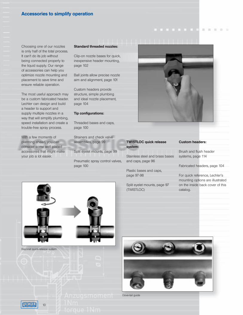
Choosing one of our nozzles is only half of the total process. It can’t do its job without being connected properly to the liquid supply. Our range of accessories can help you optimize nozzle mounting and placement to save time and ensure reliable operation.
The most useful approach may be a custom fabricated header. Lechler can design and build a header to support and supply multiple nozzles in a way that will simplify plumbing, speed installation and create a trouble-free spray process.
With a few moments of planning ahead, you can consider some well placed accessories that might make your job a lot easier.
Standard threaded nozzles:
Clip-on nozzle bases for quick, inexpensive header mounting, page 102
Ball joints allow precise nozzle aim and alignment, page 101
Custom headers provide structure, simple plumbing and ideal nozzle placement, page 104
Tip configurations: Threaded bases and caps, page 100
Strainers and check valve assemblies, page 99
Split eyelet mounts, page 99
Pneumatic spray control valves, page 100
TWISTLOC quick release system:
Stainless steel and brass bases and caps, page 96
Plastic bases and caps, page 97-98
Split eyelet mounts, page 97 (TWISTLOC)
Custom headers:
Brush and flush header systems, page 114
Fabricated headers, page 104
For quick reference, Lechler’s mounting options are illustrated on the inside back cover of this catalog.
Dove-tail guide
Bayonet quick-release system
Accessories to simplify operation
11
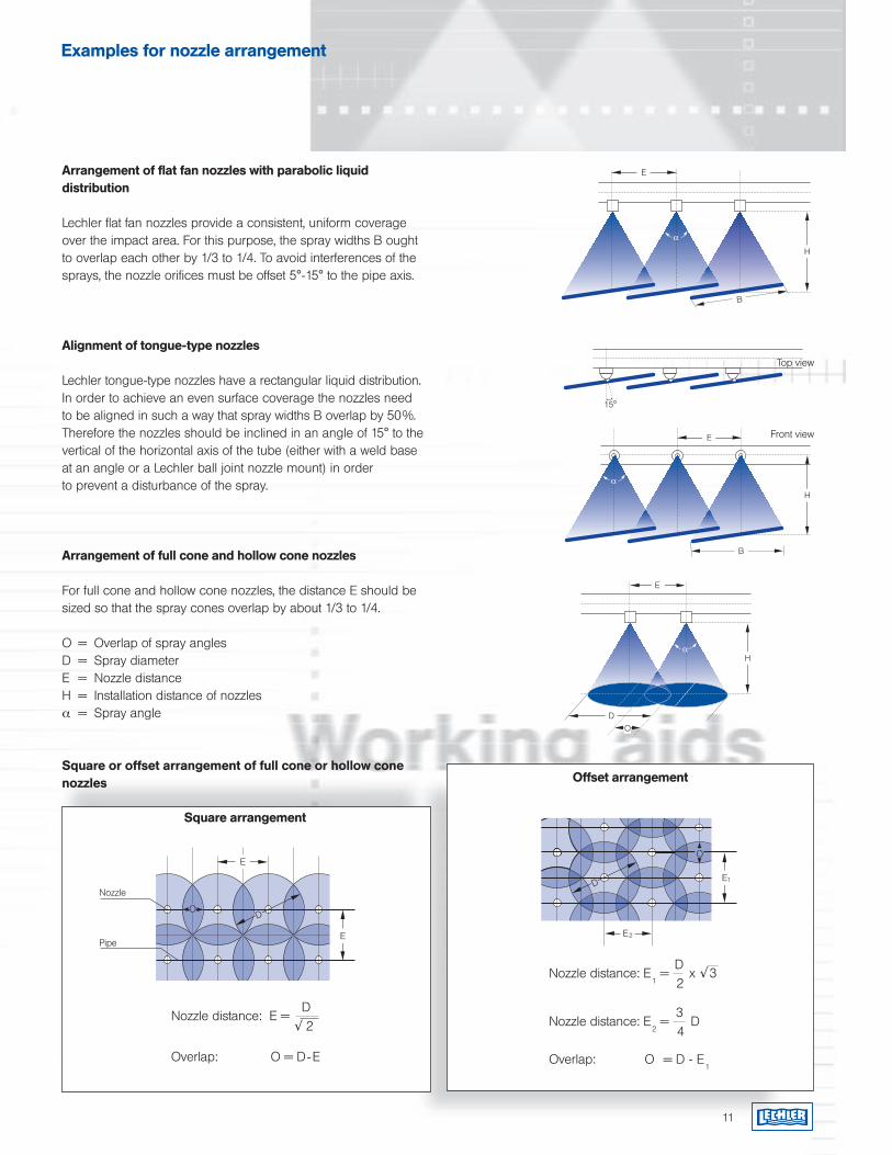
Nozzle distance: E = D
√ 2
Overlap: O = D-E
Nozzle distance: E1 =
D x √ 3
2
Nozzle distance: E2 =
3 D
4
Overlap: O = D - E1
Arrangement of flat fan nozzles with parabolic liquid distribution
Lechler flat fan nozzles provide a consistent, uniform coverage over the impact area. For this purpose, the spray widths B ought to overlap each other by 1/3 to 1/4. To avoid interferences of the sprays, the nozzle orifices must be offset 5°-15° to the pipe axis.
Alignment of tongue-type nozzles
Lechler tongue-type nozzles have a rectangular liquid distribution. In order to achieve an even surface coverage the nozzles need to be aligned in such a way that spray widths B overlap by 50%. Therefore the nozzles should be inclined in an angle of 15° to the vertical of the horizontal axis of the tube (either with a weld base at an angle or a Lechler ball joint nozzle mount) in order to prevent a disturbance of the spray.
Arrangement of full cone and hollow cone nozzles
For full cone and hollow cone nozzles, the distance E should be sized so that the spray cones overlap by about 1/3 to 1/4.
O = Overlap of spray anglesD = Spray diameterE = Nozzle distanceH = Installation distance of nozzlesα = Spray angle
Square or offset arrangement of full cone or hollow cone nozzles Offset arrangement
Square arrangement
Examples for nozzle arrangement
B
E
α
H
E
α
OD
H
Pipe
Nozzle
E
DO
EO
E1D
E2
Top view
Front view
1/2” 1.6 1.0 0.8 1.0 3.1 0.4 17.6 5.2 3/4” 2.1 1.4 1.1 1.4 4.1 0.6 23.3 6.9 1” 2.6 1.7 1.4 1.8 5.3 0.7 29.7 8.7 1-1/4” 3.5 2.3 1.8 2.3 6.9 0.9 39.1 11.5 1-1/2” 4.0 2.7 2.2 2.7 8.1 1.1 45.6 13.4 2” 5.2 3.5 2.8 3.5 10.3 1.4 58.6 17.2 2-1/2” 6.2 4.1 3.3 4.1 12.3 1.7 70.0 20.6 3” 7.7 5.1 4.1 5.1 15.3 2.0 86.9 25.5 4” 10.1 7.0 5.4 6.7 20.1 2.7 114 33.6 6” 15.2 11.0 8.1 10.1 30.3 4.0 172 50.5
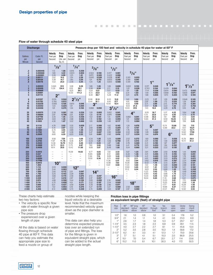
Design properties of pipe
Pressure drop per 100 feet and velocity in schedule 40 pipe for water at 60° F
Cubic Ft.per
Second
VelocityFeet per Second
Flow of water through schedule 40 steel pipe
Discharge
Gallonsper
Minute
Press. DropLbs. per Sq. In.
VelocityFeet per Second
Press. Droppsi
VelocityFeet per Second
Press. Droppsi
1/8" 1/4" 3/8" 1/2"3/4"
1" 11/4"
2"
11/2"
21/2"3"
31/2"4"
5"
6"
8"
10"12"
14"16"
18"
.2 0.000446 1.13 1.86 0.616 0.359 .3 0.000668 1.69 4.22 0.924 0.903 0.504 0.159 0.317 0.061 .4 0.000891 2.26 6.98 1.23 1.61 0.672 0.345 0.422 0.086 .5 0.00111 2.82 10.5 1.54 2.39 0.840 0.539 0.528 0.167 0.301 0.033 .6 0.00134 3.39 14.7 1.85 3.29 1.01 0.751 0.633 0.240 0.361 0.041 .8 0.00178 4.52 25.0 2.46 5.44 1.34 1.25 0.844 0.408 0.481 0.102
1 0.00223 5.565 37.2 3.08 8.28 1.68 1.85 1.06 0.600 0.602 0.155 0.371 0.048 2 0.00446 11.29 134.4 6.16 30.1 3.36 6.58 2.11 2.10 1.20 0.526 0.743 0.164 0.429 0.044 3 0.00668 9.25 64.1 5.04 13.9 3.17 4.33 1.81 1.09 1.114 0.336 0.644 0.090 0.473 0.043 4 0.00891 12.33 111.2 6.72 23.9 4.22 7.42 2.41 1.83 1.49 0.565 0.858 0.150 0.630 0.071 5 0.01114 8.40 36.7 5.28 11.2 3.01 2.75 1.86 0.835 1.073 0.223 0.788 0.104
6 0.01337 0.574 0.044 10.08 51.9 6.33 15.8 3.61 3.84 2.23 1.17 1.29 0.309 0.946 0.145 8 0.01782 0.765 0.073 13.44 91.1 8.45 27.7 4.81 6.60 2.97 1.99 1.72 0.518 1.26 0.241 10 0.02228 0.956 0.108 0.670 0.046 10.56 42.4 6.02 9.99 3.71 2.99 2.15 0.774 1.58 0.361 15 0.03342 1.43 0.224 1.01 0.094 9.03 21.6 5.57 6.36 3.22 1.63 2.37 0.755 20 0.04456 1.91 0.375 1.34 0.158 0.868 0.056 12.03 37.8 7.43 10.9 4.29 2.78 3.16 1.28 25 0.05570 2.39 0.561 1.68 0.234 1.09 0.083 0.812 0.041 9.28 16.7 5.37 4.22 3.94 1.93 30 0.06684 2.87 0.786 2.01 0.327 1.30 0.114 0.974 0.056 11.14 23.8 6.44 5.92 4.73 2.72 35 0.07798 3.35 1.05 2.35 0.436 1.52 0.151 1.14 0.074 0.882 0.041 12.99 32.2 7.51 7.90 5.52 3.64 40 0.08912 3.83 1.35 2.68 0.556 1.74 0.192 1.30 0.095 1.01 0.052 14.85 41.5 8.59 10.24 6.30 4.65 45 0.1003 4.30 1.67 3.02 0.668 1.95 0.239 1.46 0.117 1.13 0.064 9.67 12.80 7.09 5.85
50 0.1114 4.78 2.03 3.35 0.839 2.17 0.288 1.62 0.142 1.26 0.076 10.74 15.66 7.88 7.15 60 0.1337 5.74 2.87 4.02 1.18 2.60 0.406 1.95 0.204 1.51 0.107 12.89 22.2 9.47 10.21 70 0.1560 6.70 3.84 4.69 1.59 3.04 0.540 2.27 0.261 1.76 0.143 1.12 0.047 11.05 13.71 80 0.1782 7.65 4.97 5.36 2.03 3.47 0.687 2.60 0.334 2.02 0.180 1.28 0.060 12.62 17.59 90 0.2005 8.60 6.20 6.03 2.53 3.91 0.861 2.92 0.416 2.27 0.224 1.44 0.074 14.20 22.0
100 0.2228 9.56 7.59 6.70 3.09 4.34 1.05 3.25 0.509 2.52 0.272 1.60 0.090 1.11 0.036 15.78 26.9 125 0.2785 11.97 11.76 8.38 4.71 5.43 1.61 4.06 0.769 3.15 0.415 2.01 0.135 1.39 0.055 19.72 41.4 150 0.3342 14.36 16.70 10.05 6.69 6.51 2.24 4.87 1.08 3.78 0.580 2.41 0.190 1.67 0.077 175 0.3899 16.75 22.3 11.73 8.97 7.60 3.00 5.68 1.44 4.41 0.774 2.81 0.253 1.94 0.102 200 0.4456 19.14 28.8 13.42 11.68 8.68 3.87 6.49 1.85 5.04 0.985 3.21 0.323 2.22 0.130
225 0.5013 — — 15.09 14.63 9.77 4.83 7.30 2.32 5.67 1.23 3.61 0.401 2.50 0.162 1.44 0.043 250 0.557 — — — — 10.85 5.93 8.12 2.84 6.30 1.46 4.01 0.495 2.78 0.195 1.60 0.051 275 0.6127 — — — — 11.94 7.14 8.93 3.40 6.93 1.79 4.41 0.583 3.05 0.234 1.76 0.061 300 0.6684 — — — — 13.00 8.36 9.74 4.02 7.56 2.11 4.81 0.683 3.33 0.275 1.92 0.072 350 0.7798 — — — — 11.36 5.41 8.82 2.84 5.62 0.919 3.89 0.367 2.24 0.095 400 0.8912 — — 12.98 7.03 10.08 3.68 6.42 1.19 4.44 0.471 2.56 0.121 450 1.003 — — 14.61 8.80 11.34 4.60 7.22 1.48 5.00 0.590 2.89 0.151 500 1.114 2.03 0.059 — — 12.60 5.65 8.02 1.81 5.55 0.720 3.21 0.182 600 1.337 2.44 0.083 — — 15.12 8.04 9.63 2.55 6.66 1.02 3.85 0.258 700 1.560 2.85 0.112 2.01 0.047 — — — — 11.23 3.43 7.78 1.35 4.49 0.343 800 1.782 3.25 0.143 2.29 0.061 — — — — 12.83 4.43 8.88 1.75 5.13 0.443 900 2.005 3.66 0.179 2.58 0.075 2.13 0.047 — — 14.44 5.58 9.99 2.18 5.77 0.5541 000 2.228 4.07 0.218 2.87 0.091 2.37 0.057 — — 16.04 6.84 11.10 2.68 6.41 0.6751 200 2.674 4.88 0.306 3.44 0.128 2.85 0.080 2.18 0.042 — — 13.33 3.81 7.70 0.9481 400 3.119 5.70 0.409 4.01 0.171 3.32 0.107 2.54 0.055 — — 15.55 5.13 8.98 1.281 600 3.565 6.51 0.527 4.59 0.219 3.79 0.138 2.90 0.071 — — 17.77 6.61 10.26 1.651 800 4.010 7.32 0.663 5.16 0.276 4.27 0.172 3.27 0.088 2.58 0.050 — — 19.99 8.37 11.54 2.082 000 4.456 8.14 0.808 5.73 0.339 4.74 0.209 3.63 0.107 2.87 0.060 22.21 10.3 12.82 2.55
VelocityFeet per Second
Press. Droppsi
VelocityFeet per Second
Press. Droppsi
VelocityFeet per Second
Press. Droppsi
VelocityFeet per Second
Press. Droppsi
VelocityFeet per Second
Press. Droppsi
12
These charts help estimate two key factors:• The velocity a specific flow rate of water through a given pipe size• The pressure drop experienced over a given length of pipe
All the data is based on water flowing through schedule 40 pipe at 60o F. This data can help you estimate the appropriate pipe size to feed a nozzle or group of
nozzles while keeping the liquid velocity at a desirable level. Note that the maximum recommended velocity goes down as the pipe diameter is smaller.
This data can also help you determine expected pressure loss over an extended run of pipe and fittings. The loss for the fittings is given in equivalent straight pipe, which can be added to the actual straight pipe length.
Friction loss in pipe fittings as equivalent length (feet) of straight pipe
Pipe 90° 90° long 45° Tee Tee Gate Globe Swing size standard radius standard through branch valve valve check elbow elbow elbow flow flow open open valve
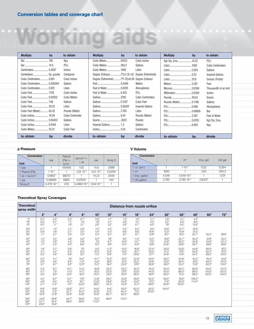
Conversion tables and coverage chart
Bar .......................................... 100 KpaBar .......................................... 14.5 P.S.I.Centimeters........................... 0.3937 InchesCentistokes ........................... Sp. gravity CentipoiseCubic Centimeters............... 0.061 Cubic Inches Cubic Centimeters............... 0.000264 GallonsCubic Centimeters............... 0.001 LitersCubic Feet ............................. 1728 Cubic InchesCubic Feet ............................. 0.02832 Cubic MetersCubic Feet ............................. 7.48 GallonsCubic Feet ............................. 28.32 LitersCubic Feet (Water).............. 62.43 Pounds (Water)Cubic Inches......................... 16.39 Cubic CentimeterCubic Inches......................... 0.00433 GallonsCubic Inches......................... 0.0164 LitersCubic Meters ........................ 35.31 Cubic Feet
Cubic Meters ........................ 61023 Cubic InchesCubic Meters ........................ 264.2 GallonsCubic Meters ........................ 1000 LitersDegree (Celsius) .................. (°Cx1.8)+32 Degree (Fahrenheit)Degree (Fahrenheit)............ (°F-32)x0.56 Degree (Celsius)Feet......................................... 0.3048 MetersFeet of Water........................ 0.0295 AtmospheresFeet of Water........................ 0.433 P.S.I.Gallons................................... 3785 Cubic CentimetersGallons................................... 0.1337 Cubic FeetGallons................................... 0.83267 Imperial GallonsGallons................................... 3.785 LitersGallons................................... 8.34 Pounds (Water)Grams .................................... .0022 PoundsImperial Gallons................... 1.2 GallonsInches..................................... 2.54 Centimeters
Kgf./Sq. Cms........................ 14.22 P.S.I.Liters ...................................... 1000 Cubic CentimetersLiters ...................................... 0.264 GallonsLiters ...................................... 0.22 Imperial GallonsLiters ...................................... 33.8 Ounces (Fluids)Meters .................................... 3.281 FeetMicrons.................................. 0.0394 Thousandth of an InchMillimeters ............................ 0.0394 InchesPounds ................................... 453.6 GramsPounds (Water).................... 0.1198 GallonsP.S.I. ........................................ 0.068 AtmospheresP.S.I. ........................................ 0.06895 BarP.S.I. ........................................ 2.307 Feet of WaterP.S.I. ........................................ 0.0703 Kgf./Sq. Cms.P.S.I. ........................................ 6.895 Kpa
Multiply by to obtain
to obtain by divide
Multiply by to obtain
to obtain by divide
Multiply by to obtain
to obtain by divide
13
11.10-5
0.98070.06895
0.479 .10-3
1000001
98070689547,9
1.021.02 .10-5
10.07031
0.4882.10-3
14.514.5 .10-5
14.221
6.94.10-3
20890.020920481441
barPascal[Pa] =N/m2
kp/cm2 = 1 at
psi lb/sq ft
p Pressure
110004.5463.785
0.222201
0.8327
0.264264.21.201
1
l m3 Imp. gal US gal
Conversion
Unit1 l (1 dm3)1 m3
1 Imp. gallon1 US gallon
V Volume
1.10-3
14.546.10-3
3.785.10-3
Conversion
Unit1 bar1 Pascal [Pa]1 at = kp/cm2
1 psi1lb/sq ft
Theoretical Spray Coverages
5° 0.2" 0.4" 0.5" 0.7" 0.9" 1.1" 1.3" 1.6" 2.1" 2.6" 3.1" 4.2" 10° 0.4" 0.7" 1.1" 1.4" 1.8" 2.1" 2.6" 3.1" 4.2" 5.2" 6.3" 8.4" 15° 0.5" 1.1" 1.6" 2.1" 2.6" 3.2" 3.9" 4.7" 6.3" 7.9" 9.5" 12.6"
2" 4" 6" 8" 10" 12" 15" 18" 24" 30" 36" 48" 60" 72"
Theoreticalspray width
Distance from nozzle orifice
20° 0.7" 1.4" 2.1" 2.8" 3.5" 4.2" 5.3" 6.4" 8.5" 10.6" 12.7" 16.9" 25° 0.9" 1.8" 2.7" 3.5" 4.4" 5.3" 6.6" 8.0" 10.6" 13.3" 15.9" 21.2" 30° 1.1" 2.1" 3.2" 4.3" 5.4" 6.4" 8.1" 9.7" 12.8" 16.1" 19.3" 25.7" 32.2" 38.6"
35° 1.3" 2.5" 3.8" 5.0" 6.3" 7.6" 9.5" 11.3" 15.5" 18.9" 22.7" 30.3" 37.8" 45.4" 40° 1.5" 2.9" 4.4" 5.8" 7.3" 8.7" 10.9" 13.1" 17.5" 21.8" 26.2" 34.9" 43.6" 52.4" 45° 1.7" 3.3" 5.0" 6.6" 8.3" 9.9" 12.4" 14.9" 19.9" 24.8" 29.8" 39.7" 49.6" 59.6"
50° 1.9" 3.7" 5.6" 7.5" 9.3" 11.2" 14.0" 16.8" 22.4" 28.0" 33.6" 44.8" 56.0" 67.2" 55° 2.1" 4.2" 6.3" 8.3" 10.3" 12.5" 15.6" 18.7" 25.0" 31.2" 37.5" 50.0" 62.4" 75.0" 60° 2.3" 4.6" 6.9" 9.2" 11.5" 13.8" 17.3" 20.6" 27.7" 34.6" 41.6" 55.4" 69.2" 83.0"
65° 2.5" 5.1" 7.6" 10.2" 12.7" 15.3" 19.2" 22.9" 30.5" 38.2" 45.8" 61.2" 76.4" 91.6" 70° 2.8" 5.6" 8.4" 11.2" 14.0" 16.8" 21.0" 25.2" 33.6" 42.0" 50.4" 67.2" 84.0" 101.0" 75° 3.1" 6.1" 9.2" 12.3" 15.3" 18.4" 23.0" 27.6" 36.8" 46.0" 55.2" 73.6" 92.0" 110.0"
80° 3.4" 6.7" 10.1" 13.4" 16.8" 20.2" 25.2" 30.3" 40.3" 50.4" 60.4" 80.6" 101.0" 121.0" 85° 3.7" 7.3" 11.0" 14.7" 18.3" 22.0" 27.5" 33.0" 44.0" 55.0" 66.0" 88.0" 110.0" 132.0" 90° 4.0" 8.0" 12.0" 16.0" 20.0" 24.0" 30.0" 36.0" 48.0" 60.0" 72.0" 96.0" 120.0" 144.0"
95° 4.4" 8.7" 13.1" 17.5" 21.8" 26.2" 32.8" 39.3" 52.4" 65.5" 78.6" 105.0" 100° 4.8" 9.5" 14.3" 19.1" 23.8" 28.6" 35.8" 43.0" 57.2" 71.6" 85.9" 114.0" 110° 5.7" 11.4" 17.1" 22.8" 28.5" 34.3" 42.8" 51.4" 68.5" 85.6" 103.0"
120° 6.9" 13.9" 20.8" 27.7" 34.6" 41.6" 52.0" 62.4" 83.2" 104.0" 130° 8.6" 17.2" 25.7" 34.3" 42.9" 51.5" 64.4" 77.3" 103.0" 140° 10.9" 21.9" 32.9" 43.8" 54.8" 65.7" 82.2" 98.6"
150° 14.9" 29.8" 44.7" 59.6" 74.5" 89.5" 112.0" 160° 22.7" 45.4" 68.0" 90.6" 113.0" 170° 45.8" 91.6"
14
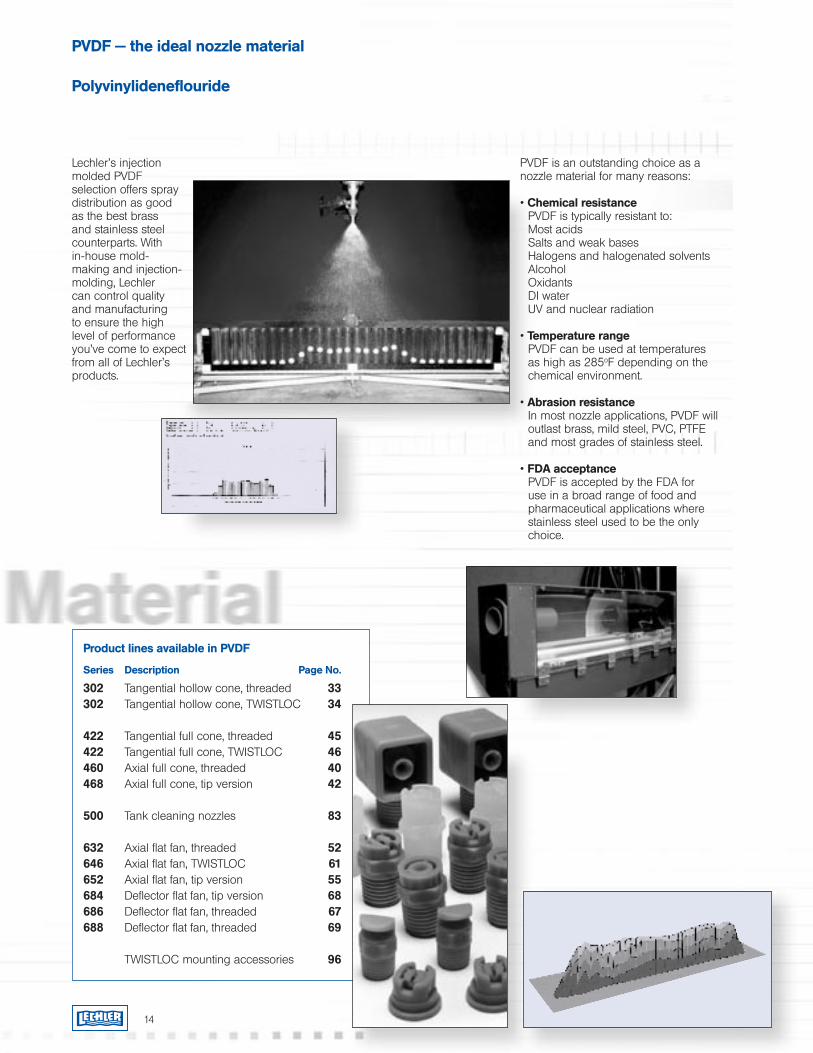
Lechler’s injection molded PVDF selection offers spray distribution as good as the best brass and stainless steel counterparts. With in-house mold-making and injection-molding, Lechler can control quality and manufacturing to ensure the high level of performance you’ve come to expect from all of Lechler’s products.
PVDF — the ideal nozzle material
Polyvinylideneflouride
PVDF is an outstanding choice as a nozzle material for many reasons:
• Chemical resistance PVDF is typically resistant to:Most acidsSalts and weak basesHalogens and halogenated solventsAlcoholOxidantsDI waterUV and nuclear radiation
• Temperature rangePVDF can be used at temperatures as high as 285oF depending on the chemical environment.
• Abrasion resistanceIn most nozzle applications, PVDF will outlast brass, mild steel, PVC, PTFE and most grades of stainless steel.
• FDA acceptancePVDF is accepted by the FDA for use in a broad range of food and pharmaceutical applications where stainless steel used to be the only choice.
Product lines available in PVDF
Series Description Page No.
302 Tangential hollow cone, threaded 33302 Tangential hollow cone, TWISTLOC 34
422 Tangential full cone, threaded 45422 Tangential full cone, TWISTLOC 46460 Axial full cone, threaded 40468 Axial full cone, tip version 42
500 Tank cleaning nozzles 83
632 Axial flat fan, threaded 52646 Axial flat fan, TWISTLOC 61652 Axial flat fan, tip version 55684 Deflector flat fan, tip version 68686 Deflector flat fan, threaded 67688 Deflector flat fan, threaded 69
TWISTLOC mounting accessories 96
15
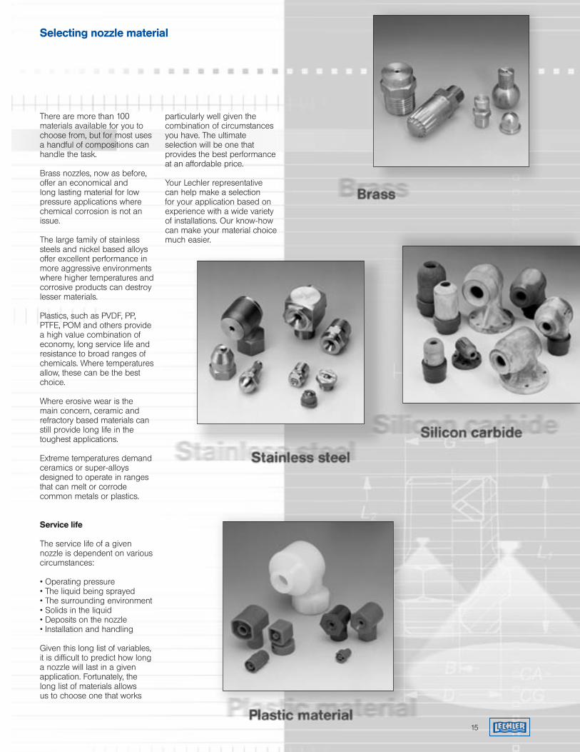
Selecting nozzle material
There are more than 100 materials available for you to choose from, but for most uses a handful of compositions can handle the task.
Brass nozzles, now as before, offer an economical and long lasting material for low pressure applications where chemical corrosion is not an issue.
The large family of stainless steels and nickel based alloys offer excellent performance in more aggressive environments where higher temperatures and corrosive products can destroy lesser materials.
Plastics, such as PVDF, PP, PTFE, POM and others provide a high value combination of economy, long service life and resistance to broad ranges of chemicals. Where temperatures allow, these can be the best choice.
Where erosive wear is the main concern, ceramic and refractory based materials can still provide long life in the toughest applications.
Extreme temperatures demand ceramics or super-alloys designed to operate in ranges that can melt or corrode common metals or plastics.
Service life
The service life of a given nozzle is dependent on various circumstances:
• Operating pressure• The liquid being sprayed• The surrounding environment• Solids in the liquid• Deposits on the nozzle• Installation and handling
Given this long list of variables, it is difficult to predict how long a nozzle will last in a given application. Fortunately, the long list of materials allows us to choose one that works
particularly well given the combination of circumstances you have. The ultimate selection will be one that provides the best performance at an affordable price.
Your Lechler representative can help make a selection for your application based on experience with a wide variety of installations. Our know-how can make your material choice much easier.
16
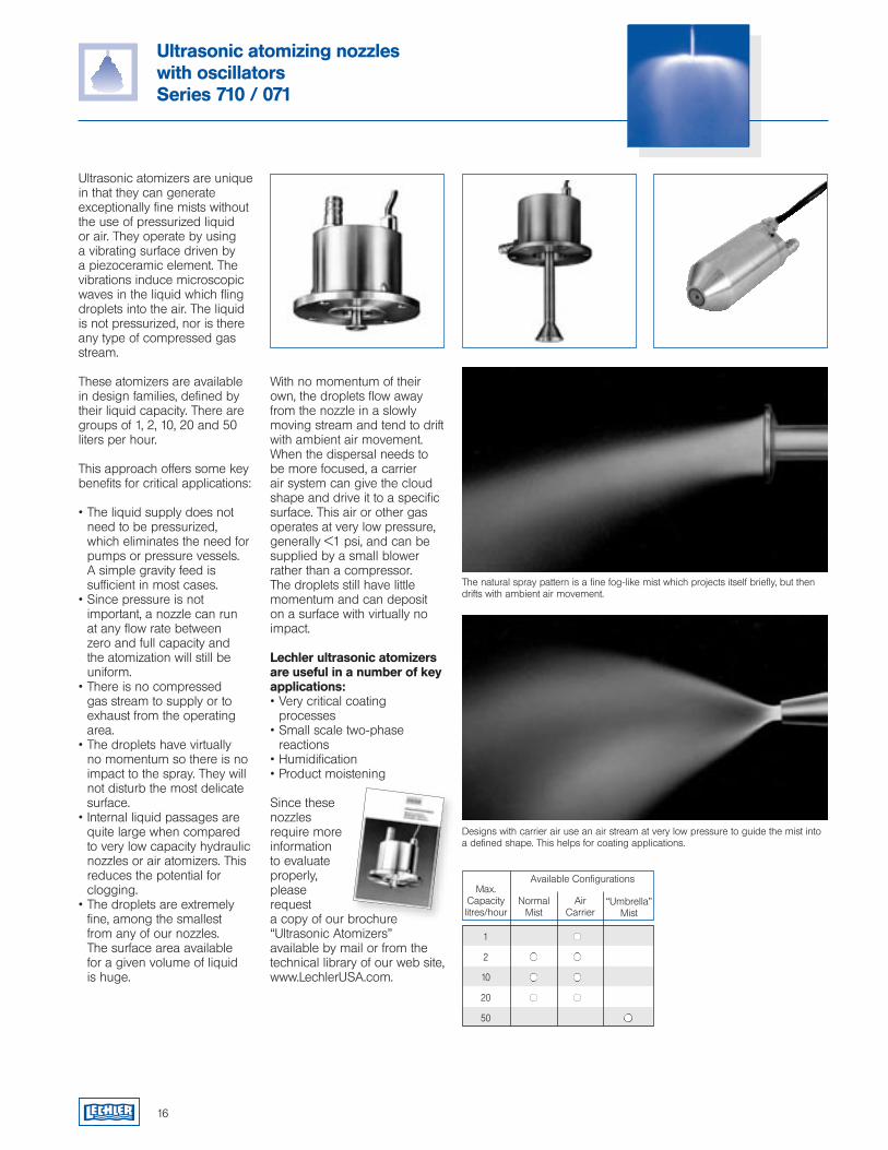
The natural spray pattern is a fine fog-like mist which projects itself briefly, but then drifts with ambient air movement.
Ultrasonic atomizing nozzleswith oscillatorsSeries 710 / 071
Designs with carrier air use an air stream at very low pressure to guide the mist into a defined shape. This helps for coating applications.
Ultrasonic atomizers are unique in that they can generate exceptionally fine mists without the use of pressurized liquid or air. They operate by using a vibrating surface driven by a piezoceramic element. The vibrations induce microscopic waves in the liquid which fling droplets into the air. The liquid is not pressurized, nor is there any type of compressed gas stream.
These atomizers are available in design families, defined by their liquid capacity. There are groups of 1, 2, 10, 20 and 50 liters per hour.
This approach offers some key benefits for critical applications:
• The liquid supply does not need to be pressurized, which eliminates the need for pumps or pressure vessels. A simple gravity feed is sufficient in most cases.
• Since pressure is not important, a nozzle can run at any flow rate between zero and full capacity and the atomization will still be uniform.
• There is no compressed gas stream to supply or to exhaust from the operating area.
• The droplets have virtually no momentum so there is no impact to the spray. They will not disturb the most delicate surface.
• Internal liquid passages are quite large when compared to very low capacity hydraulic nozzles or air atomizers. This reduces the potential for clogging.
• The droplets are extremely fine, among the smallest from any of our nozzles. The surface area available for a given volume of liquid is huge.
With no momentum of their own, the droplets flow away from the nozzle in a slowly moving stream and tend to drift with ambient air movement. When the dispersal needs to be more focused, a carrier air system can give the cloud shape and drive it to a specific surface. This air or other gas operates at very low pressure, generally <1 psi, and can be supplied by a small blower rather than a compressor. The droplets still have little momentum and can deposit on a surface with virtually no impact.
Lechler ultrasonic atomizers are useful in a number of key applications:• Very critical coating processes• Small scale two-phase reactions• Humidification• Product moistening
Since these nozzles require more information to evaluate properly, please request a copy of our brochure “Ultrasonic Atomizers” available by mail or from the technical library of our web site, www.LechlerUSA.com.
Available Configurations
NormalMist
Max.Capacitylitres/hour
Air Carrier
“Umbrella”Mist
1
2
10
20
50

Air atomizing nozzlesAtomization of viscous liquidsCoolingGas coolingHumidification of airHumidification of goodsLubricationWeb dampeningand many others...
18
Introduction
Air atomizing nozzles are available in various designs to generate specific spray and flow requirements:
Siphon principle (self-aspirating)
Gravity principle(supply located above the nozzle)
Pressure principle(supply from a pressurized source)
Internal or external mix Full cone or flat fan spray
pattern
Air atomizing nozzles offer wide ranges of liquid flow turn-down which influences the droplet size. This can be controlled using the accessories shown on the next page.
The regulating device allows control of the liquid supply for any nozzle or supply mode.
The pneumatic valve allows very quick on/off action of the liquid flow using external control.
The quick-cleaning device allows an operator to push a pin through the liquid orifice to clear clogs.
The regulating device with quick cleaning needle provides the orifice clearing function combined with liquid flow control.
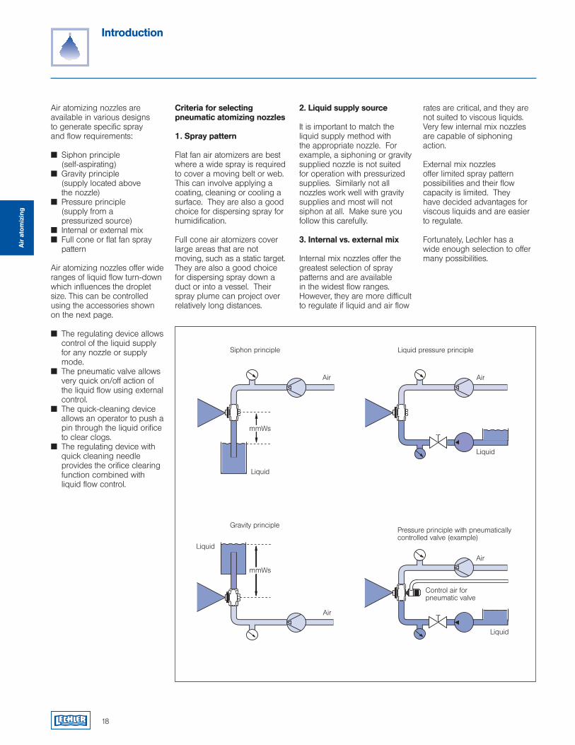
Criteria for selecting pneumatic atomizing nozzles
1. Spray pattern
Flat fan air atomizers are best where a wide spray is required to cover a moving belt or web. This can involve applying a coating, cleaning or cooling a surface. They are also a good choice for dispersing spray for humidification.
Full cone air atomizers cover large areas that are not moving, such as a static target. They are also a good choice for dispersing spray down a duct or into a vessel. Their spray plume can project over relatively long distances.
2. Liquid supply source
It is important to match the liquid supply method with the appropriate nozzle. For example, a siphoning or gravity supplied nozzle is not suited for operation with pressurized supplies. Similarly not all nozzles work well with gravity supplies and most will not siphon at all. Make sure you follow this carefully.
3. Internal vs. external mix
Internal mix nozzles offer the greatest selection of spray patterns and are available in the widest flow ranges. However, they are more difficult to regulate if liquid and air flow
rates are critical, and they are not suited to viscous liquids. Very few internal mix nozzles are capable of siphoning action.
External mix nozzles offer limited spray pattern possibilities and their flow capacity is limited. They have decided advantages for viscous liquids and are easier to regulate.
Fortunately, Lechler has a wide enough selection to offer many possibilities.
Liquid
mmWs
Air
Siphon principle
Gravity principle
Liquid
Air
Liquid pressure principle
Liquid
Air
Control air for pneumatic valve
Pressure principle with pneumatically controlled valve (example)
Liquid
mmWs
Air
Air
ato
miz
ing
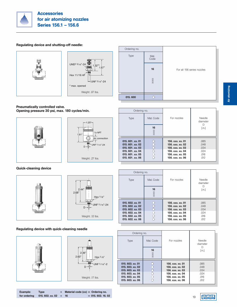
015. 601. xx. 01 156. xxx. xx. 01 .085015. 601. xx. 02 156. xxx. xx. 02 .048015. 601. xx. 03 156. xxx. xx. 03 .034015. 601. xx. 04 156. xxx. xx. 04 .024015. 601. xx. 05 156. xxx. xx. 05 .016015. 601. xx. 06 156. xxx. xx. 06 .012
For nozzles
Ordering no.
Mat. Code
303S
S
16
Type
19
Accessories for air atomizing nozzlesSeries 156.1 – 156.6
015. 600
For all 156 series nozzles
Needle diameter
D[ in.]
015. 602. xx. 01 156. xxx. xx. 01 .085015. 602. xx. 02 156. xxx. xx. 02 .048015. 602. xx. 03 156. xxx. xx. 03 .034015. 602. xx. 04 156. xxx. xx. 04 .024015. 602. xx. 05 156. xxx. xx. 05 .016015. 602. xx. 06 156. xxx. xx. 06 .012
For nozzles
Ordering no.
Mat. Code
303S
S
16
Type Needle diameter
D[ in.]
015. 603. xx. 01 156. xxx. xx. 01 .085015. 603. xx. 02 156. xxx. xx. 02 .048015. 603. xx. 03 156. xxx. xx. 03 .034015. 603. xx. 04 156. xxx. xx. 04 .024015. 603. xx. 05 156. xxx. xx. 05 .016015. 603. xx. 06 156. xxx. xx. 06 .012
For nozzles
Ordering no.
Mat. Code
303S
S
16
Type Needle diameter
D[ in.]
Quick-cleaning device
Pneumatically controlled valve.Opening pressure 30 psi, max. 180 cycles/min.
Regulating device and shutting-off needle:
Regulating device with quick-cleaning needle
Weight: .12 lbs.
Weight: .27 lbs.
Weight: .071 lbs.
Weight: .17 lbs.
�����������
������������
�������������
������������
�������������
Weight: .07 lbs.
����������
�
����� ���
����� �������
�����
�����
��������������
�������
����� ��������
�����
�����
�
Hex � ���
����� �������
Air
ato
miz
ing
Ordering no.
Mat. Code
303S
S
16
Type
Example: Type + Material code (xx) = Ordering no.for ordering 015. 602. xx. 02 + 16 = 015. 602. 16. 02
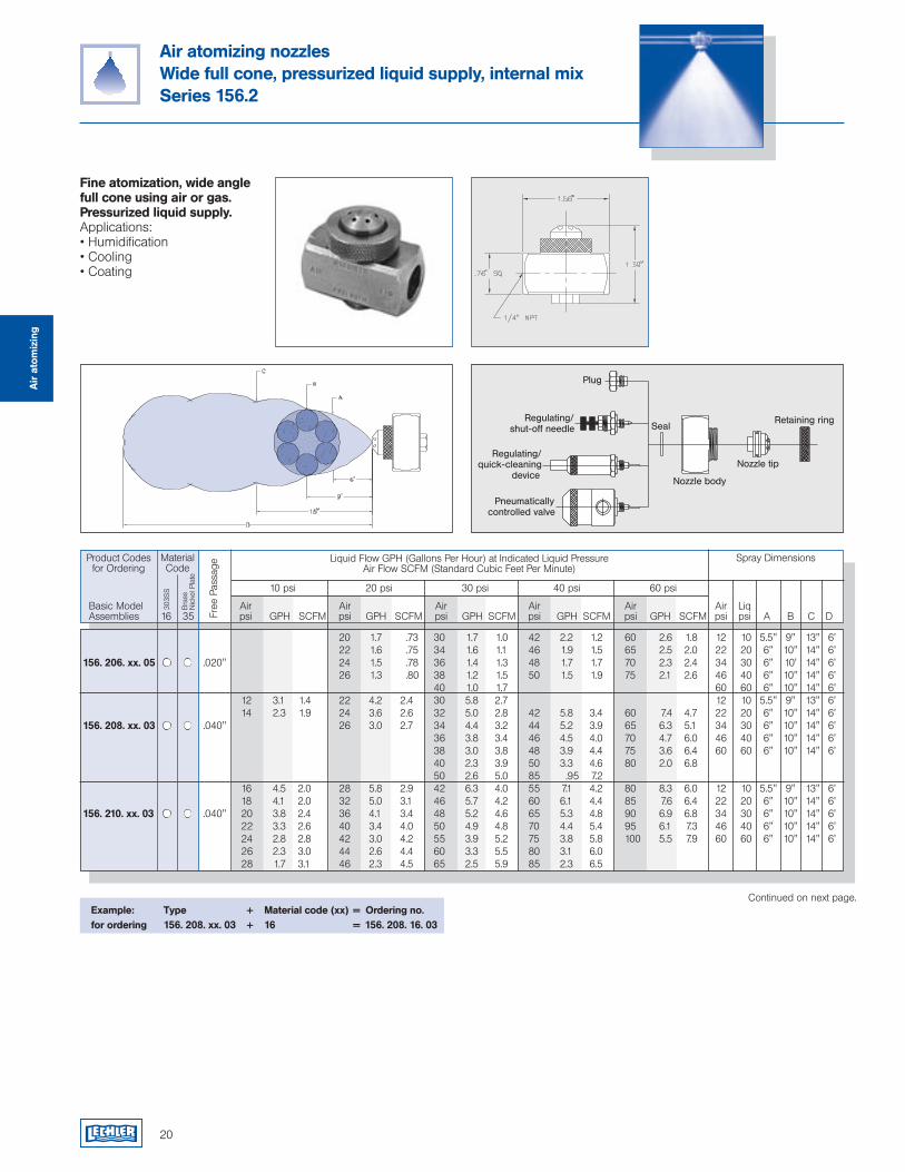
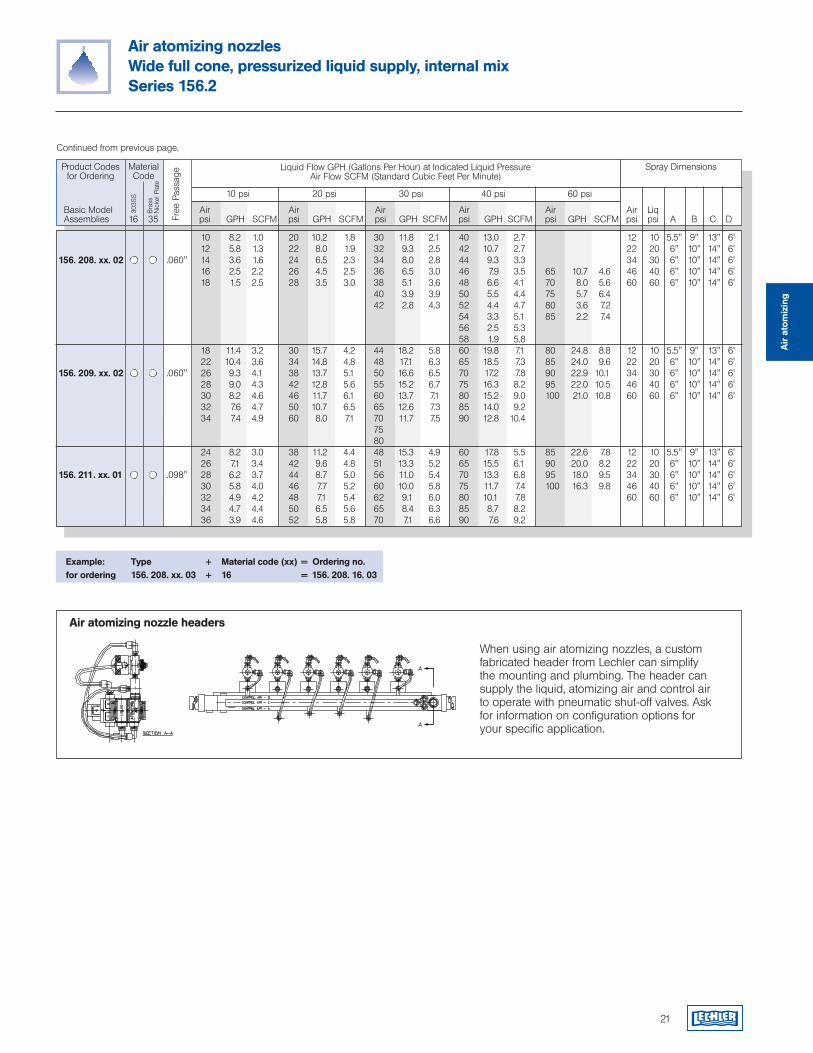
Air atomizing nozzlesWide full cone, pressurized liquid supply, internal mixSeries 156.2
Fine atomization, wide angle full cone using air or gas. Pressurized liquid supply.Applications:• Humidification• Cooling• Coating
Example: Type + Material code (xx) = Ordering no.for ordering 156. 208. xx. 03 + 16 = 156. 208. 16. 03
Continued on next page.
Air
ato
miz
ing
20 1.7 .73 30 1.7 1.0 42 2.2 1.2 60 2.6 1.8 12 10 5.5" 9" 13" 6' 22 1.6 .75 34 1.6 1.1 46 1.9 1.5 65 2.5 2.0 22 20 6" 10" 14" 6' 156. 206. xx. 05 .020" 24 1.5 .78 36 1.4 1.3 48 1.7 1.7 70 2.3 2.4 34 30 6" 10' 14" 6' 26 1.3 .80 38 1.2 1.5 50 1.5 1.9 75 2.1 2.6 46 40 6" 10" 14" 6' 40 1.0 1.7 60 60 6" 10" 14" 6' 12 3.1 1.4 22 4.2 2.4 30 5.8 2.7 12 10 5.5" 9" 13" 6' 14 2.3 1.9 24 3.6 2.6 32 5.0 2.8 42 5.8 3.4 60 7.4 4.7 22 20 6" 10" 14" 6'156. 208. xx. 03 .040" 26 3.0 2.7 34 4.4 3.2 44 5.2 3.9 65 6.3 5.1 34 30 6" 10" 14" 6' 36 3.8 3.4 46 4.5 4.0 70 4.7 6.0 46 40 6" 10" 14" 6' 38 3.0 3.8 48 3.9 4.4 75 3.6 6.4 60 60 6" 10" 14" 6' 40 2.3 3.9 50 3.3 4.6 80 2.0 6.8 50 2.6 5.0 85 .95 7.2 16 4.5 2.0 28 5.8 2.9 42 6.3 4.0 55 7.1 4.2 80 8.3 6.0 12 10 5.5" 9" 13" 6' 18 4.1 2.0 32 5.0 3.1 46 5.7 4.2 60 6.1 4.4 85 7.6 6.4 22 20 6" 10" 14" 6'156. 210. xx. 03 .040" 20 3.8 2.4 36 4.1 3.4 48 5.2 4.6 65 5.3 4.8 90 6.9 6.8 34 30 6" 10" 14" 6' 22 3.3 2.6 40 3.4 4.0 50 4.9 4.8 70 4.4 5.4 95 6.1 7.3 46 40 6" 10" 14" 6' 24 2.8 2.8 42 3.0 4.2 55 3.9 5.2 75 3.8 5.8 100 5.5 7.9 60 60 6" 10" 14" 6' 26 2.3 3.0 44 2.6 4.4 60 3.3 5.5 80 3.1 6.0 28 1.7 3.1 46 2.3 4.5 65 2.5 5.9 85 2.3 6.5
Product Codesfor Ordering
Liquid Flow GPH (Gallons Per Hour) at Indicated Liquid PressureAir Flow SCFM (Standard Cubic Feet Per Minute)
10 psi 20 psi 30 psi 40 psi 60 psi
Spray Dimensions
Free
Pas
sage
Basic Model Air Air Air Air Air Air Liq Assemblies psi GPH SCFM psi GPH SCFM psi GPH SCFM psi GPH SCFM psi GPH SCFM psi psi A B C D
MaterialCode
303S
S
Bra
ss
Nic
kel P
late
16 35
20
21
When using air atomizing nozzles, a custom fabricated header from Lechler can simplify the mounting and plumbing. The header can supply the liquid, atomizing air and control air to operate with pneumatic shut-off valves. Ask for information on configuration options for your specific application.
Air atomizing nozzle headers
Air
ato
miz
ing
10 8.2 1.0 20 10.2 1.8 30 11.8 2.1 40 13.0 2.7 12 10 5.5" 9" 13" 6' 12 5.8 1.3 22 8.0 1.9 32 9.3 2.5 42 10.7 2.7 22 20 6" 10" 14" 6'156. 208. xx. 02 .060" 14 3.6 1.6 24 6.5 2.3 34 8.0 2.8 44 9.3 3.3 34 30 6" 10" 14" 6' 16 2.5 2.2 26 4.5 2.5 36 6.5 3.0 46 7.9 3.5 65 10.7 4.6 46 40 6" 10" 14" 6' 18 1.5 2.5 28 3.5 3.0 38 5.1 3.6 48 6.6 4.1 70 8.0 5.6 60 60 6" 10" 14" 6' 40 3.9 3.9 50 5.5 4.4 75 5.7 6.4 42 2.8 4.3 52 4.4 4.7 80 3.6 7.2 54 3.3 5.1 85 2.2 7.4 56 2.5 5.3 58 1.9 5.8 18 11.4 3.2 30 15.7 4.2 44 18.2 5.8 60 19.8 7.1 80 24.8 8.8 12 10 5.5" 9" 13" 6' 22 10.4 3.6 34 14.8 4.8 48 17.1 6.3 65 18.5 7.3 85 24.0 9.6 22 20 6" 10" 14" 6'156. 209. xx. 02 .060" 26 9.3 4.1 38 13.7 5.1 50 16.6 6.5 70 17.2 7.8 90 22.9 10.1 34 30 6" 10" 14" 6' 28 9.0 4.3 42 12.8 5.6 55 15.2 6.7 75 16.3 8.2 95 22.0 10.5 46 40 6" 10" 14" 6' 30 8.2 4.6 46 11.7 6.1 60 13.7 7.1 80 15.2 9.0 100 21.0 10.8 60 60 6" 10" 14" 6' 32 7.6 4.7 50 10.7 6.5 65 12.6 7.3 85 14.0 9.2 34 7.4 4.9 60 8.0 7.1 70 11.7 7.5 90 12.8 10.4 75 80 24 8.2 3.0 38 11.2 4.4 48 15.3 4.9 60 17.8 5.5 85 22.6 7.8 12 10 5.5" 9" 13" 6' 26 7.1 3.4 42 9.6 4.8 51 13.3 5.2 65 15.5 6.1 90 20.0 8.2 22 20 6" 10" 14" 6'156. 211. xx. 01 .098" 28 6.2 3.7 44 8.7 5.0 56 11.0 5.4 70 13.3 6.8 95 18.0 9.5 34 30 6" 10" 14" 6' 30 5.8 4.0 46 7.7 5.2 60 10.0 5.8 75 11.7 7.4 100 16.3 9.8 46 40 6" 10" 14" 6' 32 4.9 4.2 48 7.1 5.4 62 9.1 6.0 80 10.1 7.8 60 60 6" 10" 14" 6' 34 4.7 4.4 50 6.5 5.6 65 8.4 6.3 85 8.7 8.2 36 3.9 4.6 52 5.8 5.8 70 7.1 6.6 90 7.6 9.2
Air atomizing nozzlesWide full cone, pressurized liquid supply, internal mixSeries 156.2
Continued from previous page.
Example: Type + Material code (xx) = Ordering no.for ordering 156. 208. xx. 03 + 16 = 156. 208. 16. 03
Product Codesfor Ordering
Liquid Flow GPH (Gallons Per Hour) at Indicated Liquid PressureAir Flow SCFM (Standard Cubic Feet Per Minute)
10 psi 20 psi 30 psi 40 psi 60 psi
Spray DimensionsFr
ee P
assa
ge
Basic Model Air Air Air Air Air Air Liq Assemblies psi GPH SCFM psi GPH SCFM psi GPH SCFM psi GPH SCFM psi GPH SCFM psi psi A B C D
MaterialCode
303S
S
Bra
ss
Nic
kel P
late
16 35
22
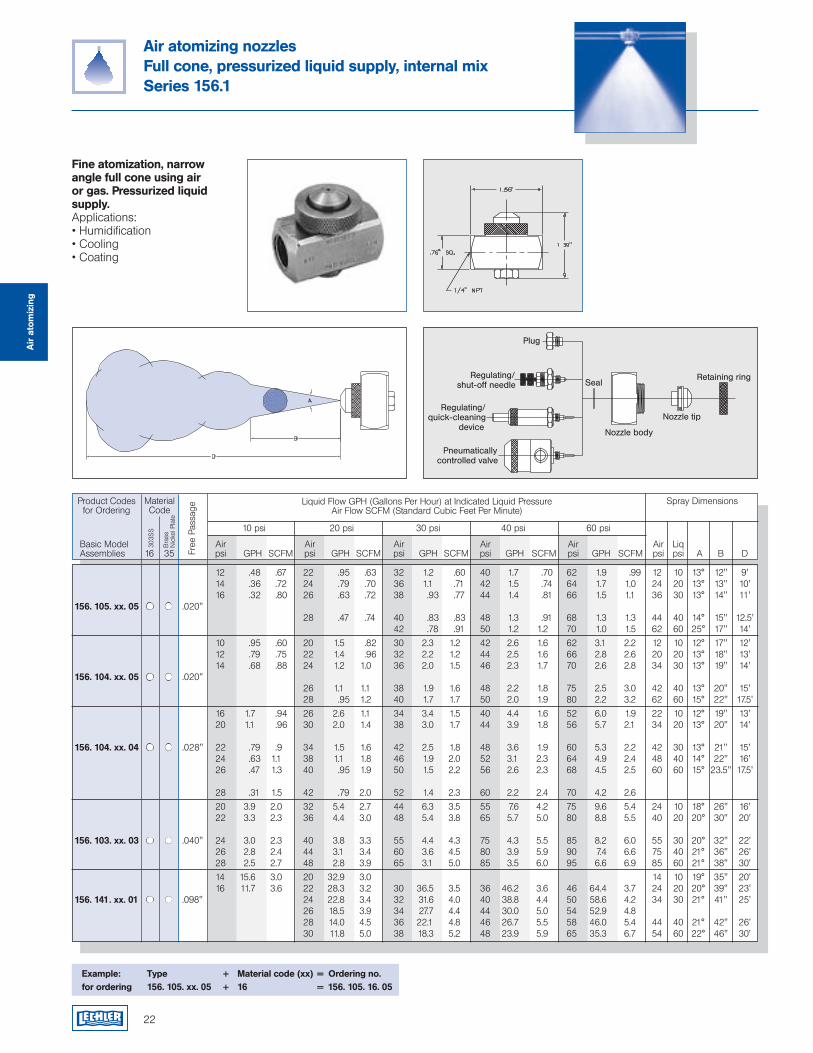
Air atomizing nozzlesFull cone, pressurized liquid supply, internal mixSeries 156.1
Fine atomization, narrow angle full cone using air or gas. Pressurized liquid supply.Applications:• Humidification• Cooling• Coating
Example: Type + Material code (xx) = Ordering no.for ordering 156. 105. xx. 05 + 16 = 156. 105. 16. 05
Air
ato
miz
ing
12 .48 .67 22 .95 .63 32 1.2 .60 40 1.7 .70 62 1.9 .99 12 10 13° 12" 9' 14 .36 .72 24 .79 .70 36 1.1 .71 42 1.5 .74 64 1.7 1.0 24 20 13° 13" 10' 16 .32 .80 26 .63 .72 38 .93 .77 44 1.4 .81 66 1.5 1.1 36 30 13° 14" 11'156. 105. xx. 05 .020" 28 .47 .74 40 .83 .83 48 1.3 .91 68 1.3 1.3 44 40 14° 15" 12.5' 42 .78 .91 50 1.2 1.2 70 1.0 1.5 62 60 25° 17" 14'
10 .95 .60 20 1.5 .82 30 2.3 1.2 42 2.6 1.6 62 3.1 2.2 12 10 12° 17" 12' 12 .79 .75 22 1.4 .96 32 2.2 1.2 44 2.5 1.6 66 2.8 2.6 20 20 13° 18" 13' 14 .68 .88 24 1.2 1.0 36 2.0 1.5 46 2.3 1.7 70 2.6 2.8 34 30 13° 19" 14'156. 104. xx. 05 .020" 26 1.1 1.1 38 1.9 1.6 48 2.2 1.8 75 2.5 3.0 42 40 13° 20" 15' 28 .95 1.2 40 1.7 1.7 50 2.0 1.9 80 2.2 3.2 62 60 15° 22" 17.5'
16 1.7 .94 26 2.6 1.1 34 3.4 1.5 40 4.4 1.6 52 6.0 1.9 22 10 12° 19" 13' 20 1.1 .96 30 2.0 1.4 38 3.0 1.7 44 3.9 1.8 56 5.7 2.1 34 20 13° 20" 14'
156. 104. xx. 04 .028" 22 .79 .9 34 1.5 1.6 42 2.5 1.8 48 3.6 1.9 60 5.3 2.2 42 30 13° 21" 15' 24 .63 1.1 38 1.1 1.8 46 1.9 2.0 52 3.1 2.3 64 4.9 2.4 48 40 14° 22" 16' 26 .47 1.3 40 .95 1.9 50 1.5 2.2 56 2.6 2.3 68 4.5 2.5 60 60 15° 23.5" 17.5'
28 .31 1.5 42 .79 2.0 52 1.4 2.3 60 2.2 2.4 70 4.2 2.6
20 3.9 2.0 32 5.4 2.7 44 6.3 3.5 55 7.6 4.2 75 9.6 5.4 24 10 18° 26" 16' 22 3.3 2.3 36 4.4 3.0 48 5.4 3.8 65 5.7 5.0 80 8.8 5.5 40 20 20° 30" 20'
156. 103. xx. 03 .040" 24 3.0 2.3 40 3.8 3.3 55 4.4 4.3 75 4.3 5.5 85 8.2 6.0 55 30 20° 32" 22' 26 2.8 2.4 44 3.1 3.4 60 3.6 4.5 80 3.9 5.9 90 7.4 6.6 75 40 21° 36" 26' 28 2.5 2.7 48 2.8 3.9 65 3.1 5.0 85 3.5 6.0 95 6.6 6.9 85 60 21° 38" 30'
14 15.6 3.0 20 32.9 3.0 14 10 19° 35" 20' 16 11.7 3.6 22 28.3 3.2 30 36.5 3.5 36 46.2 3.6 46 64.4 3.7 24 20 20° 39" 23' 156. 141. xx. 01 .098" 24 22.8 3.4 32 31.6 4.0 40 38.8 4.4 50 58.6 4.2 34 30 21° 41" 25'
26 18.5 3.9 34 27.7 4.4 44 30.0 5.0 54 52.9 4.8 28 14.0 4.5 36 22.1 4.8 46 26.7 5.5 58 46.0 5.4 44 40 21° 42" 26' 30 11.8 5.0 38 18.3 5.2 48 23.9 5.9 65 35.3 6.7 54 60 22° 46" 30'
Product Codesfor Ordering
Liquid Flow GPH (Gallons Per Hour) at Indicated Liquid PressureAir Flow SCFM (Standard Cubic Feet Per Minute)
10 psi 20 psi 30 psi 40 psi 60 psi
Spray Dimensions
Free
Pas
sage
Basic Model Air Air Air Air Air Air Liq Assemblies psi GPH SCFM psi GPH SCFM psi GPH SCFM psi GPH SCFM psi GPH SCFM psi psi A B D
MaterialCode
303S
S
Bra
ss
Nic
kel P
late
16 35
10 .99 .72 .63 .57 .44 .38 .31 .12 10 7" 8" 10" 6'156. 523. xx. 04 .028" 20 1.4 .50 .47 .41 .36 .33 .30 .20 20 8" 10" 13" 7' 30 1.9 .30 .25 .23 .22 .20 .17 .09 30 8.5" 12" 14" 7' 20 1.3 1.2 1.1 .96 .72 .69 .60 .39 20 8" 12" 14.5" 9'156. 521. xx. 03 .040" 30 1.7 1.0 .98 .89 .88 .87 .76 .56 30 9" 12.5" 15" 10' 40 2.2 .95 .85 .76 .69 .68 .60 .45 40 9" 12.04" 15. 11' 50 2.6 .68 .63 .60 .58 .55 .47 .34 50 9" 12.04" 15" 12'
20 1.5 1.5 1.4 1.2 1.2 1.1 .96 .71 20 7" 9" 12" 9' 30 2.0 1.4 4.3 1.3 1.3 1.3 1.2 .99 30 8" 10" 13" 11'156. 519. xx. 03 .040" 40 2.2 1.3 1.2 1.2 1.2 1.1 1.0 .91 40 8" 10" 13" 13' 50 3.0 1.1 1.0 1.0 1.0 1.0 .91 .77 50 8" 10" 13" 13' 60 3.2 .90 .87 .80 .76 .72 .64 .52 60 8" 10" 13" 13'
23
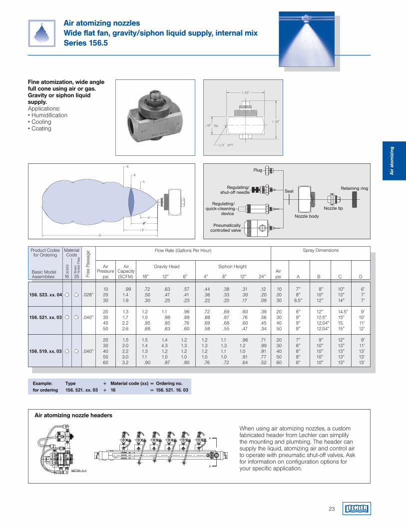
Air atomizing nozzlesWide flat fan, gravity/siphon liquid supply, internal mixSeries 156.5
Fine atomization, wide angle full cone using air or gas. Gravity or siphon liquid supply.Applications:• Humidification• Cooling• Coating
Example: Type + Material code (xx) = Ordering no.for ordering 156. 521. xx. 03 + 16 = 156. 521. 16. 03
Free
Pas
sage
303S
S
Bra
ss
Nic
kel P
late
16 35
Product Codesfor Ordering
Flow Rate (Gallons Per Hour)
Air Air Gravity Head Siphon Height Pressure Capacity Air
Spray DimensionsMaterialCode
Basic Model Assemblies psi (SCFM) 18" 12" 6" 4" 8" 12" 24" psi A B C D
When using air atomizing nozzles, a custom fabricated header from Lechler can simplify the mounting and plumbing. The header can supply the liquid, atomizing air and control air to operate with pneumatic shut-off valves. Ask for information on configuration options for your specific application.
Air atomizing nozzle headers
Air
ato
miz
ing
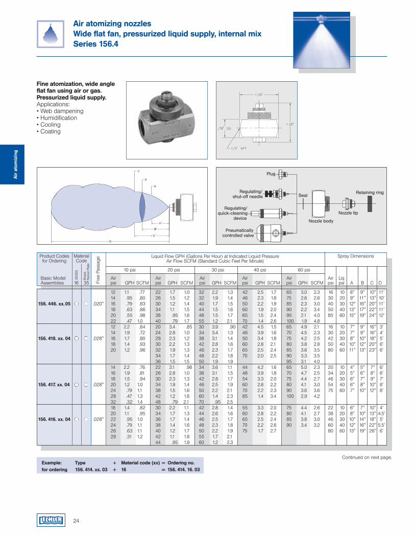
Air atomizing nozzlesWide flat fan, pressurized liquid supply, internal mixSeries 156.4
Fine atomization, wide angle flat fan using air or gas. Pressurized liquid supply.Applications:• Web dampening• Humidification• Cooling• Coating
24
Continued on next page.Example: Type + Material code (xx) = Ordering no.for ordering 156. 414. xx. 03 + 16 = 156. 414. 16. 03
12 1.1 .77 22 1.7 1.0 32 2.2 1.3 42 2.5 1.7 65 3.0 2.3 16 10 8" 9" 10" 11' 14 .95 .80 26 1.5 1.2 32 1.9 1.4 46 2.3 1.8 75 2.6 2.6 30 20 9" 11" 13" 10'156. 446. xx. 05 .020" 16 .79 .83 30 1.2 1.4 40 1.7 1.5 50 2.2 1.9 85 2.3 3.0 40 30 12" 16" 20" 11' 18 .63 .86 34 1.1 1.5 44 1.5 1.6 60 1.9 2.0 90 2.2 3.4 50 40 13" 17" 22" 11' 20 .55 .98 38 .95 1.6 48 1.5 1.7 65 1.5 2.4 95 2.1 4.0 85 60 15" 19" 24" 12' 22 .47 1.0 40 .79 1.7 55 1.2 2.1 70 1.4 2.6 100 1.9 4.8 12 2.2 .64 20 3.4 .85 30 3.9 .90 42 4.5 1.5 65 4.9 2.1 16 10 7" 9" 16" 3' 14 1.9 .72 24 2.8 1.0 34 3.4 1.3 46 3.9 1.6 70 4.5 2.3 30 20 7" 9" 16" 4'156. 418. xx. 04 .028" 16 1.7 .80 28 2.3 1.2 38 3.1 1.4 50 3.4 1.8 75 4.2 2.5 42 30 8" 10" 18" 5' 18 1.4 .93 30 2.2 1.3 42 2.8 1.6 60 2.8 2.1 80 3.8 2.8 50 40 10" 12" 20" 6' 20 1.2 .96 32 1.9 1.3 46 2.3 1.7 65 2.5 2.4 85 3.6 3.5 80 60 11" 13" 23" 6' 34 1.7 1.4 48 2.2 1.8 70 2.0 2.5 90 3.3 3.5 36 1.5 1.5 50 1.9 1.9 95 3.1 4.0 14 2.2 .76 22 3.1 .98 34 3.6 1.1 44 4.2 1.6 65 5.0 2.3 20 10 4" 5" 7" 6' 16 1.9 .81 26 2.8 1.0 38 3.1 1.5 48 3.9 1.8 70 4.7 2.5 34 20 5" 6" 8" 6' 18 1.5 .94 30 2.3 1.3 42 2.8 1.7 54 3.3 2.0 75 4.4 2.7 46 30 6" 7" 9" 7'156. 417. xx. 04 .028" 20 1.2 1.0 34 1.9 1.4 46 2.5 1.9 60 2.8 2.2 80 4.1 3.0 54 40 6" 8" 10" 8' 24 .79 1.1 38 1.5 1.6 50 2.2 2.1 70 2.2 2.3 90 3.6 3.6 75 60 7" 10" 12" 8' 28 .47 1.3 42 1.2 1.8 60 1.4 2.3 85 1.4 3.4 100 2.9 4.2 32 .32 1.4 48 .79 2.1 70 .95 2.5 18 1.4 .82 30 2.2 1.1 42 2.8 1.4 55 3.3 2.0 75 4.4 2.6 22 10 6" 7" 10" 4' 20 1.1 .95 34 1.7 1.3 44 2.6 1.6 60 2.8 2.2 80 4.1 2.7 38 20 8" 10" 13" 4.5'156. 416. xx. 04 .028" 22 .95 1.0 36 1.7 1.4 46 2.5 1.7 65 2.5 2.4 85 3.8 3.0 46 30 10" 14" 18" 5' 24 .79 1.1 38 1.4 1.6 48 2.3 1.8 70 2.2 2.6 90 3.4 3.2 60 40 12" 16" 22" 5.5' 26 .63 1.1 40 1.2 1.7 50 2.2 1.9 75 1.7 2.7 80 60 13" 19" 26" 6' 28 .31 1.2 42 1.1 1.8 55 1.7 2.1 44 .95 1.9 60 1.2 2.3
Air
ato
miz
ing
Product Codesfor Ordering
Liquid Flow GPH (Gallons Per Hour) at Indicated Liquid PressureAir Flow SCFM (Standard Cubic Feet Per Minute)
10 psi 20 psi 30 psi 40 psi 60 psi
Spray Dimensions
Free
Pas
sage
Basic Model Air Air Air Air Air Air Liq Assemblies psi GPH SCFM psi GPH SCFM psi GPH SCFM psi GPH SCFM psi GPH SCFM psi psi A B C D
MaterialCode
303S
S
Bra
ss
Nic
kel P
late
16 35
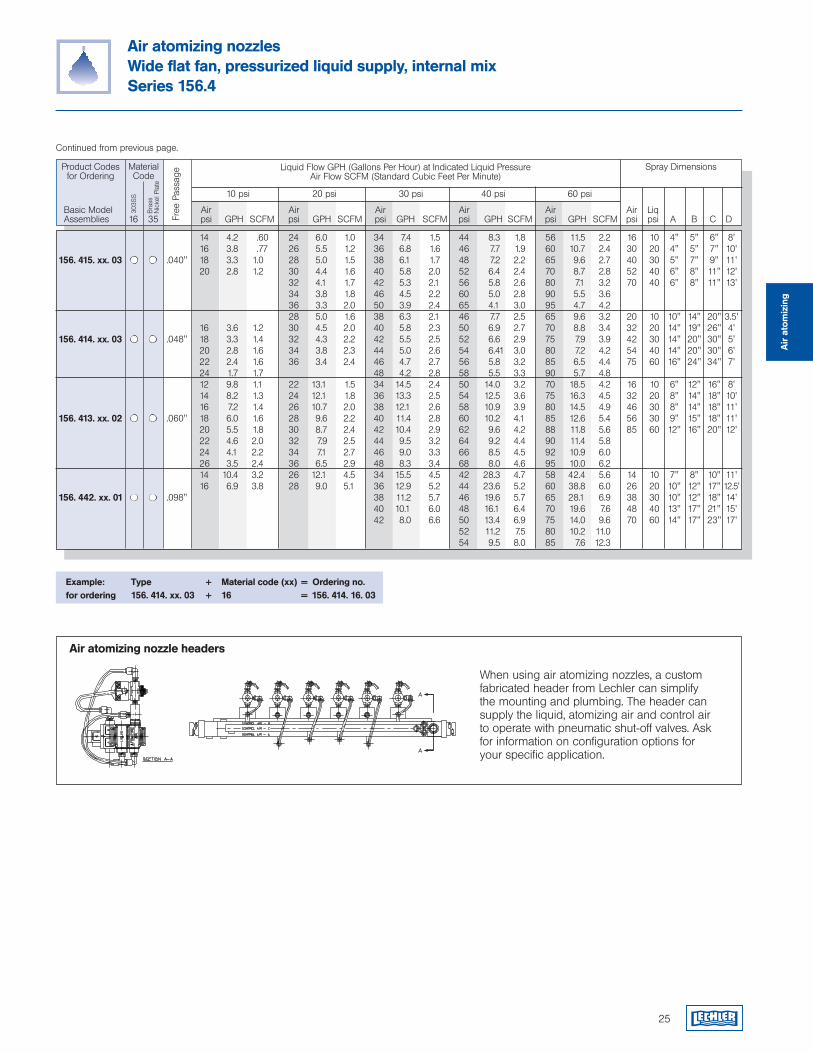
Example: Type + Material code (xx) = Ordering no.for ordering 156. 414. xx. 03 + 16 = 156. 414. 16. 03
Air atomizing nozzlesWide flat fan, pressurized liquid supply, internal mixSeries 156.4
Continued from previous page.
25
When using air atomizing nozzles, a custom fabricated header from Lechler can simplify the mounting and plumbing. The header can supply the liquid, atomizing air and control air to operate with pneumatic shut-off valves. Ask for information on configuration options for your specific application.
Air atomizing nozzle headers
Air
ato
miz
ing
14 4.2 .60 24 6.0 1.0 34 7.4 1.5 44 8.3 1.8 56 11.5 2.2 16 10 4" 5" 6" 8' 16 3.8 .77 26 5.5 1.2 36 6.8 1.6 46 7.7 1.9 60 10.7 2.4 30 20 4" 5" 7" 10'156. 415. xx. 03 .040" 18 3.3 1.0 28 5.0 1.5 38 6.1 1.7 48 7.2 2.2 65 9.6 2.7 40 30 5" 7" 9" 11' 20 2.8 1.2 30 4.4 1.6 40 5.8 2.0 52 6.4 2.4 70 8.7 2.8 52 40 6" 8" 11" 12' 32 4.1 1.7 42 5.3 2.1 56 5.8 2.6 80 7.1 3.2 70 40 6" 8" 11" 13' 34 3.8 1.8 46 4.5 2.2 60 5.0 2.8 90 5.5 3.6 36 3.3 2.0 50 3.9 2.4 65 4.1 3.0 95 4.7 4.2 28 5.0 1.6 38 6.3 2.1 46 7.7 2.5 65 9.6 3.2 20 10 10" 14" 20" 3.5' 16 3.6 1.2 30 4.5 2.0 40 5.8 2.3 50 6.9 2.7 70 8.8 3.4 32 20 14" 19" 26" 4' 156. 414. xx. 03 .048" 18 3.3 1.4 32 4.3 2.2 42 5.5 2.5 52 6.6 2.9 75 7.9 3.9 42 30 14" 20" 30" 5' 20 2.8 1.6 34 3.8 2.3 44 5.0 2.6 54 6.41 3.0 80 7.2 4.2 54 40 14" 20" 30" 6' 22 2.4 1.6 36 3.4 2.4 46 4.7 2.7 56 5.8 3.2 85 6.5 4.4 75 60 16" 24" 34" 7' 24 1.7 1.7 48 4.2 2.8 58 5.5 3.3 90 5.7 4.8 12 9.8 1.1 22 13.1 1.5 34 14.5 2.4 50 14.0 3.2 70 18.5 4.2 16 10 6" 12" 16" 8' 14 8.2 1.3 24 12.1 1.8 36 13.3 2.5 54 12.5 3.6 75 16.3 4.5 32 20 8" 14" 18" 10' 16 7.2 1.4 26 10.7 2.0 38 12.1 2.6 58 10.9 3.9 80 14.5 4.9 46 30 8" 14" 18" 11'156. 413. xx. 02 .060" 18 6.0 1.6 28 9.6 2.2 40 11.4 2.8 60 10.2 4.1 85 12.6 5.4 56 30 9" 15" 18" 11' 20 5.5 1.8 30 8.7 2.4 42 10.4 2.9 62 9.6 4.2 88 11.8 5.6 85 60 12" 16" 20" 12' 22 4.6 2.0 32 7.9 2.5 44 9.5 3.2 64 9.2 4.4 90 11.4 5.8 24 4.1 2.2 34 7.1 2.7 46 9.0 3.3 66 8.5 4.5 92 10.9 6.0 26 3.5 2.4 36 6.5 2.9 48 8.3 3.4 68 8.0 4.6 95 10.0 6.2 14 10.4 3.2 26 12.1 4.5 34 15.5 4.5 42 28.3 4.7 58 42.4 5.6 14 10 7" 8" 10" 11' 16 6.9 3.8 28 9.0 5.1 36 12.9 5.2 44 23.6 5.2 60 38.8 6.0 26 20 10" 12" 17" 12.5' 156. 442. xx. 01 .098" 38 11.2 5.7 46 19.6 5.7 65 28.1 6.9 38 30 10" 12" 18" 14' 40 10.1 6.0 48 16.1 6.4 70 19.6 7.6 48 40 13" 17" 21" 15' 42 8.0 6.6 50 13.4 6.9 75 14.0 9.6 70 60 14" 17" 23" 17' 52 11.2 7.5 80 10.2 11.0 54 9.5 8.0 85 7.6 12.3
Product Codesfor Ordering
Liquid Flow GPH (Gallons Per Hour) at Indicated Liquid PressureAir Flow SCFM (Standard Cubic Feet Per Minute)
10 psi 20 psi 30 psi 40 psi 60 psi
Spray DimensionsFr
ee P
assa
ge
Basic Model Air Air Air Air Air Air Liq Assemblies psi GPH SCFM psi GPH SCFM psi GPH SCFM psi GPH SCFM psi GPH SCFM psi psi A B C D
MaterialCode
303S
S
Bra
ss
Nic
kel P
late
16 35
26
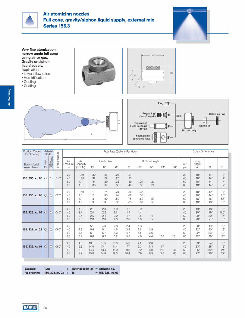
Air atomizing nozzlesFull cone, gravity/siphon liquid supply, external mixSeries 156.3
Very fine atomization, narrow angle full cone using air or gas. Gravity or siphon liquid supply.Applications:• Lowest flow rates• Humidification• Cooling• Coating
Example: Type + Material code (xx) = Ordering no.for ordering 156. 328. xx. 03 + 16 = 156. 328. 16. 03
Free
Pas
sage
303S
S
Bra
ss
Nic
kel P
late
16 35
20 .39 .30 .25 .23 .21 20 18° 14" 7'156. 330. xx. 06 .016" 40 .93 .32 .27 .25 .25 40 18° 14" 7' 60 1.4 .34 .29 .28 .30 .24 .20 60 18° 14" 7' 80 1.8 .36 .32 .30 .40 .30 .24 80 18° 14" 7'
20 .60 1.1 .75 .70 .50 .37 20 18° 12" 7'156. 330. xx. 05 .020" 40 1.0 1.2 .80 .74 .62 .53 40 18° 14" 7.5' 60 1.4 1.3 .90 .80 .78 .62 .59 60 18° 16" 8.5' 80 1.9 1.3 1.0 .90 .85 .67 .53 80 18° 18" 10'
20 1.3 2.1 2.0 1.9 1.2 .92 20 19° 18" 9'156. 328. xx. 03 .040" 40 2.1 2.4 2.2 2.1 1.5 1.4 40 20° 19" 11.5' 60 2.7 2.6 2.4 2.2 1.7 1.5 1.4 60 20° 20" 14' 80 3.6 2.8 2.6 2.3 2.0 1.6 1.5 80 20° 21" 16'
20 2.6 5.1 4.6 2.8 2.4 1.3 20 20° 19" 12'156. 327. xx. 02 .060" 40 3.6 5.6 5.1 4.5 3.8 3.1 2.9 40 22° 20" 16' 60 5.1 6.1 5.7 5.3 4.7 4.1 3.6 60 22° 23" 19' 80 6.4 6.6 6.2 5.7 5.5 4.9 4.4 2.3 1.2 80 22° 28" 21'
20 4.0 13.1 11.5 10.0 5.3 4.1 2.0 20 23° 24" 15'156. 326. xx. 01 .060" 40 5.9 14.0 13.1 11.4 7.7 6.3 5.3 1.7 40 23° 28" 18' 60 6.9 14.4 13.4 11.9 9.6 7.2 6.0 2.0 .47 60 25° 32" 24' 80 7.2 15.0 14.0 12.3 10.4 7.9 6.9 3.8 .63 80 27° 36" 27'
Air
ato
miz
ing
Product Codesfor Ordering
Flow Rate (Gallons Per Hour)
Air Air Gravity Head Siphon Height Spray Pressure Capacity Air Angle
Spray DimensionsMaterialCode
Basic Model Assemblies psi (SCFM) 18" 12" 6" 4" 8" 12" 24" 36" psi A B D
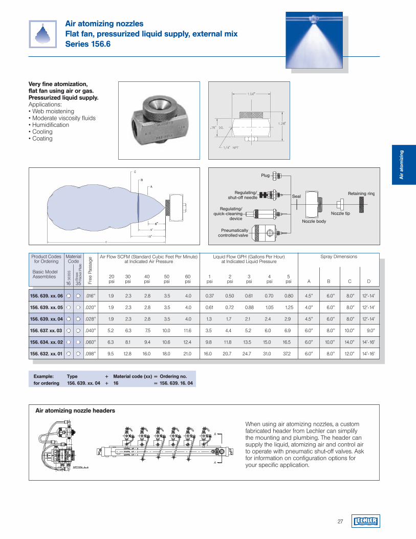
Air atomizing nozzlesFlat fan, pressurized liquid supply, external mixSeries 156.6
Very fine atomization, flat fan using air or gas. Pressurized liquid supply.Applications:• Web moistening• Moderate viscosity fluids• Humidification• Cooling• Coating
Example: Type + Material code (xx) = Ordering no.for ordering 156. 639. xx. 04 + 16 = 156. 639. 16. 04
27
When using air atomizing nozzles, a custom fabricated header from Lechler can simplify the mounting and plumbing. The header can supply the liquid, atomizing air and control air to operate with pneumatic shut-off valves. Ask for information on configuration options for your specific application.
Air atomizing nozzle headers
156. 639. xx. 06 .016" 1.9 2.3 2.8 3.5 4.0 0.37 0.50 0.61 0.70 0.80 4.5" 6.0" 8.0" 12'-14'
156. 639. xx. 05 .020" 1.9 2.3 2.8 3.5 4.0 0.61 0.72 0.88 1.05 1.25 4.0" 6.0" 8.0" 12'-14'
156. 639. xx. 04 .028" 1.9 2.3 2.8 3.5 4.0 1.3 1.7 2.1 2.4 2.9 4.5" 6.0" 8.0" 12'-14'
156. 637. xx. 03 .040" 5.2 6.3 7.5 10.0 11.6 3.5 4.4 5.2 6.0 6.9 6.0" 8.0" 10.0" 9.0"
156. 634. xx. 02 .060" 6.3 8.1 9.4 10.6 12.4 9.8 11.8 13.5 15.0 16.5 6.0" 10.0" 14.0" 14'-16'
156. 632. xx. 01 .098" 9.5 12.8 16.0 18.0 21.0 16.0 20.7 24.7 31.0 37.2 6.0" 8.0" 12.0" 14'-16'
Air
ato
miz
ing
Product Codesfor Ordering
Liquid Flow GPH (Gallons Per Hour) at Indicated Liquid Pressure
Spray Dimensions
Free
Pas
sage
Basic Model Assemblies 20 30 40 50 60 1 2 3 4 5 psi psi psi psi psi psi psi psi psi psi A B C D
MaterialCode
303S
S
Bra
ss
Nic
kel P
late
16 35
Air Flow SCFM (Standard Cubic Feet Per Minute) at Indicated Air Pressure
28
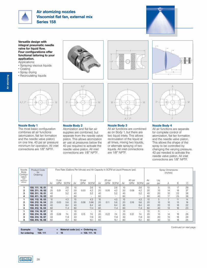
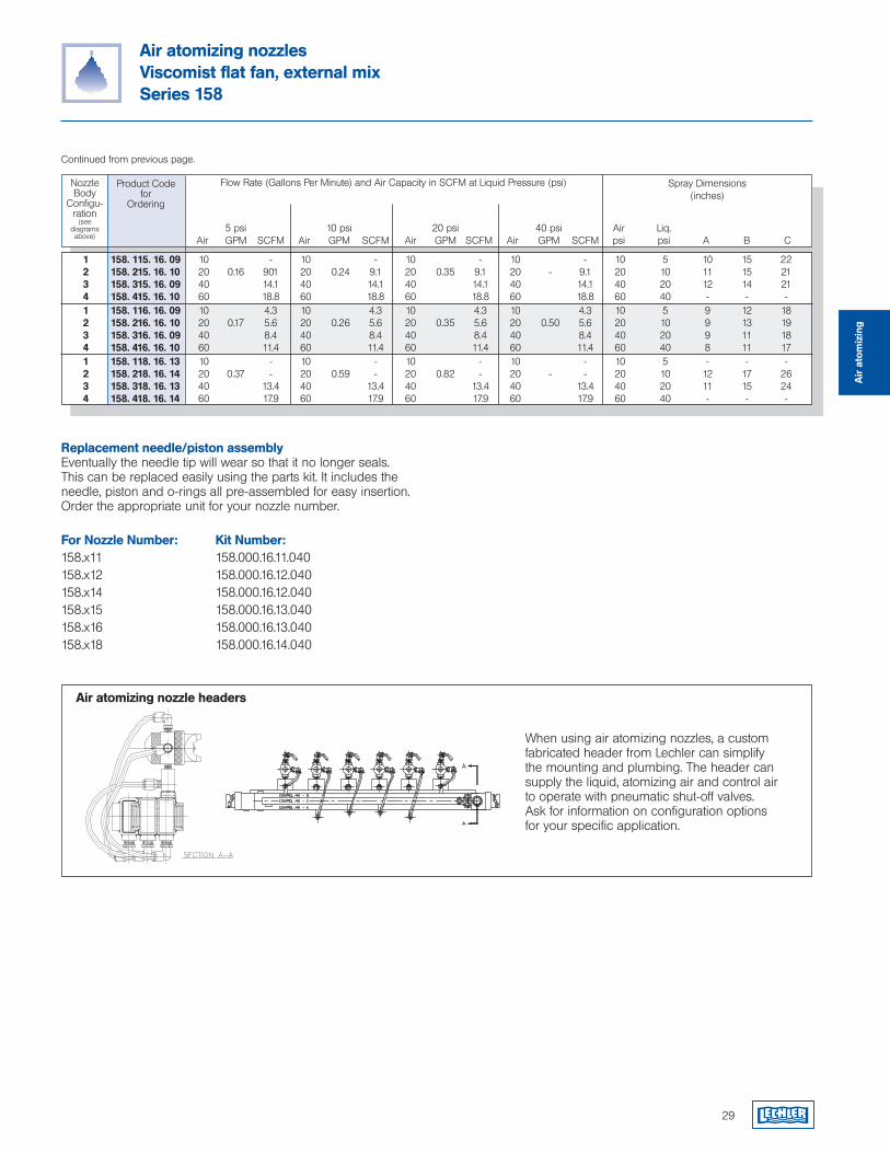
Air atomizing nozzlesViscomist flat fan, external mixSeries 158
Versatile design with integral pneumatic needle valve for liquid flow. Four configurations offer functional tailoring to your application.Applications:• Spraying viscous liquids• Coating• Spray drying• Recirculating liquids
Continued on next page.
Air
ato
miz
ing
Product Codefor
Ordering
NozzleBody
Configu-ration
(seediagrams above)
5 psi 10 psi 20 psi 40 psi Air Liq. Air GPM SCFM Air GPM SCFM Air GPM SCFM Air GPM SCFM psi psi A B C
Flow Rate (Gallons Per Minute) and Air Capacity in SCFM at Liquid Pressure (psi) Spray Dimensions(inches)
Example: Type + Material code (xx) = Ordering no.for ordering 158. 111 + 16 = 158. 111. 16
1 158. 111. 16. 01 10 2.6 10 2.6 10 2.6 10 2.6 10 5 13 17 29 2 158. 211. 16. 02 20 0.01 4.2 20 0.03 4.2 20 0.05 4.2 20 0.08 4.2 20 10 14 19 37 3 158. 311. 16. 01 40 5.2 40 5.2 40 5.2 40 5.2 40 20 15 22 38 4 158. 411. 16. 02 60 - 60 - 60 - 60 - 60 40 17 25 38 1 158. 112. 16. 03 10 4.3 10 4.3 10 4.3 10 4.3 10 5 7 11 14 2 158. 212. 16. 04 20 0.03 5.6 20 0.06 5.96 20 0.11 5.6 20 0.16 5.6 20 10 10 13 19 3 158. 312. 16. 03 40 8.4 40 8.4 40 8.4 40 8.4 40 20 13 18 22 4 158. 412. 16. 04 60 11.4 60 11.4 60 11.4 60 11.4 60 40 13 16 23 1 158. 114. 16. 07 10 - 10 - 10 - 10 - 10 5 - - - 2 158. 214. 16. 08 20 0.09 7.4 20 0.15 7.4 20 0.22 7.4 20 0.31 7.4 20 10 14 19 26 3 158. 314. 16. 07 40 11.6 40 11.6 40 11.6 40 11.6 40 20 13 18 26 4 158. 414. 16. 08 60 15.1 60 15.1 60 15.1 60 15.1 60 40 13 18 25
Nozzle Body 1The most basic configuration combines all air functions (atomization, flat fan formation and the needle valve piston) on one line. 40 psi air pressure minimum for operation. All inlet connections are 1/8" NPTF.
Nozzle Body 2Atomization and flat fan air supplies are combined, but separate from the needle valve piston. This allows atomization air use at pressures below the 40 psi required to activate the needle valve piston. All inlet connections are 1/8" NPTF.
Nozzle Body 3All air functions are combined as on Body 1, but there are two liquid inlets. This allows recirculation of the liquid at all times, mixing two liquids, or alternate sprayng of two liquids. All inlet connections are 1/8" NPTF.
Nozzle Body 4All air functions are separate for complete control of atomization, flat fan formation and the needle valve piston. This allows the shape of the spray to be controlled by changing the varying pressure. 40 psi needed to activate the needle valve piston. All inlet connections are 1/8" NPTF.
29
Air atomizing nozzlesViscomist flat fan, external mixSeries 158
Continued from previous page.
Air
ato
miz
ing
1 158. 115. 16. 09 10 - 10 - 10 - 10 - 10 5 10 15 22 2 158. 215. 16. 10 20 0.16 901 20 0.24 9.1 20 0.35 9.1 20 - 9.1 20 10 11 15 21 3 158. 315. 16. 09 40 14.1 40 14.1 40 14.1 40 14.1 40 20 12 14 21 4 158. 415. 16. 10 60 18.8 60 18.8 60 18.8 60 18.8 60 40 - - - 1 158. 116. 16. 09 10 4.3 10 4.3 10 4.3 10 4.3 10 5 9 12 18 2 158. 216. 16. 10 20 0.17 5.6 20 0.26 5.6 20 0.35 5.6 20 0.50 5.6 20 10 9 13 19 3 158. 316. 16. 09 40 8.4 40 8.4 40 8.4 40 8.4 40 20 9 11 18 4 158. 416. 16. 10 60 11.4 60 11.4 60 11.4 60 11.4 60 40 8 11 17 1 158. 118. 16. 13 10 - 10 - 10 - 10 - 10 5 - - - 2 158. 218. 16. 14 20 0.37 - 20 0.59 - 20 0.82 - 20 - - 20 10 12 17 26 3 158. 318. 16. 13 40 13.4 40 13.4 40 13.4 40 13.4 40 20 11 15 24 4 158. 418. 16. 14 60 17.9 60 17.9 60 17.9 60 17.9 60 40 - - -
NozzleBody
Configu-ration
(seediagrams above)
5 psi 10 psi 20 psi 40 psi Air Liq. Air GPM SCFM Air GPM SCFM Air GPM SCFM Air GPM SCFM psi psi A B C
Flow Rate (Gallons Per Minute) and Air Capacity in SCFM at Liquid Pressure (psi) Spray Dimensions(inches)
Product Codefor
Ordering
Replacement needle/piston assemblyEventually the needle tip will wear so that it no longer seals. This can be replaced easily using the parts kit. It includes the needle, piston and o-rings all pre-assembled for easy insertion. Order the appropriate unit for your nozzle number.
For Nozzle Number: Kit Number:158.x11 158.000.16.11.040158.x12 158.000.16.12.040158.x14 158.000.16.12.040158.x15 158.000.16.13.040158.x16 158.000.16.13.040158.x18 158.000.16.14.040
When using air atomizing nozzles, a custom fabricated header from Lechler can simplify the mounting and plumbing. The header can supply the liquid, atomizing air and control air to operate with pneumatic shut-off valves. Ask for information on configuration options for your specific application.
Air atomizing nozzle headers
Liquid Inlet Air Inlet Approx. H D NPT F NPT M Wt. lbs.
30
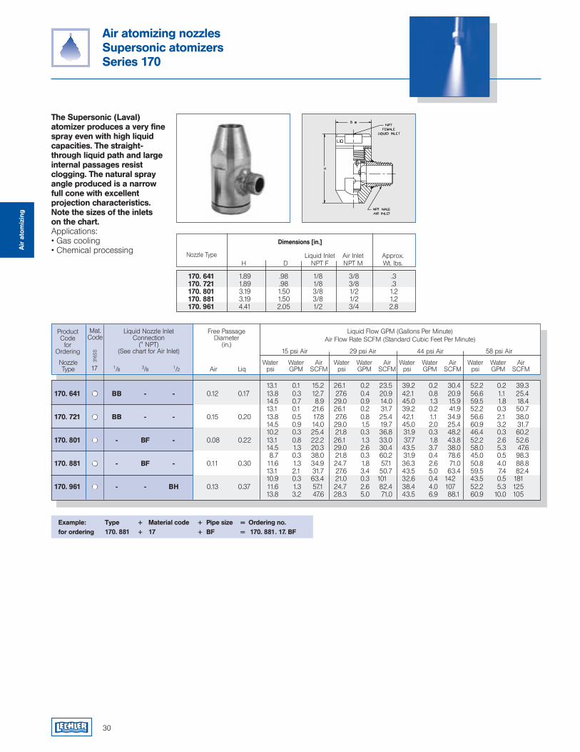
Air atomizing nozzlesSupersonic atomizersSeries 170
Nozzle Water Water Air Water Water Air Water Water Air Water Water Air Type 1/8 3/8 1/2 Air Liq psi GPM SCFM psi GPM SCFM psi GPM SCFM psi GPM SCFM
Product Code
for Ordering
Liquid Flow GPM (Gallons Per Minute) Air Flow Rate SCFM (Standard Cubic Feet Per Minute)
Liquid Nozzle InletConnection
(" NPT)(See chart for Air Inlet)
Free PassageDiameter
(in.)15 psi Air 29 psi Air 44 psi Air 58 psi Air
Nozzle Type
Dimensions [in.]
The Supersonic (Laval) atomizer produces a very fine spray even with high liquid capacities. The straight-through liquid path and large internal passages resist clogging. The natural spray angle produced is a narrow full cone with excellent projection characteristics. Note the sizes of the inlets on the chart.Applications:• Gas cooling• Chemical processingA
ir a
tom
izin
g
13.1 0.1 15.2 26.1 0.2 23.5 39.2 0.2 30.4 52.2 0.2 39.3 170. 641 BB - - 0.12 0.17 13.8 0.3 12.7 27.6 0.4 20.9 42.1 0.8 20.9 56.6 1.1 25.4 14.5 0.7 8.9 29.0 0.9 14.0 45.0 1.3 15.9 59.5 1.8 18.4 13.1 0.1 21.6 26.1 0.2 31.7 39.2 0.2 41.9 52.2 0.3 50.7 170. 721 BB - - 0.15 0.20 13.8 0.5 17.8 27.6 0.8 25.4 42.1 1.1 34.9 56.6 2.1 38.0 14.5 0.9 14.0 29.0 1.5 19.7 45.0 2.0 25.4 60.9 3.2 31.7 10.2 0.3 25.4 21.8 0.3 36.8 31.9 0.3 48.2 46.4 0.3 60.2 170. 801 - BF - 0.08 0.22 13.1 0.8 22.2 26.1 1.3 33.0 37.7 1.8 43.8 52.2 2.6 52.6 14.5 1.3 20.3 29.0 2.6 30.4 43.5 3.7 38.0 58.0 5.3 47.6 8.7 0.3 38.0 21.8 0.3 60.2 31.9 0.4 78.6 45.0 0.5 98.3 170. 881 - BF - 0.11 0.30 11.6 1.3 34.9 24.7 1.8 57.1 36.3 2.6 71.0 50.8 4.0 88.8 13.1 2.1 31.7 27.6 3.4 50.7 43.5 5.0 63.4 59.5 7.4 82.4 10.9 0.3 63.4 21.0 0.3 101 32.6 0.4 142 43.5 0.5 181 170. 961 - - BH 0.13 0.37 11.6 1.3 57.1 24.7 2.6 82.4 38.4 4.0 107 52.2 5.3 125 13.8 3.2 47.6 28.3 5.0 71.0 43.5 6.9 88.1 60.9 10.0 105
170. 641 1.89 .98 1/8 3/8 .3 170. 721 1.89 .98 1/8 3/8 .3 170. 801 3.19 1.50 3/8 1/2 1.2 170. 881 3.19 1.50 3/8 1/2 1.2 170. 961 4.41 2.05 1/2 3/4 2.8
Example: Type + Material code + Pipe size = Ordering no.for ordering 170. 881 + 17 + BF = 170. 881. 17. BF
Mat.Code
316S
S
17
AbsorptionChemical process engineeringCoolingDisinfectionDesuperheatingDust controlFire protectionFoam destructionGas treatmentHumidification of air, goods, or textilesOil sprayingProtection of storage tanksSpraying onto filtersSpraying over germinating boxesWater recoolingand many others...
Hollow cone nozzles
32
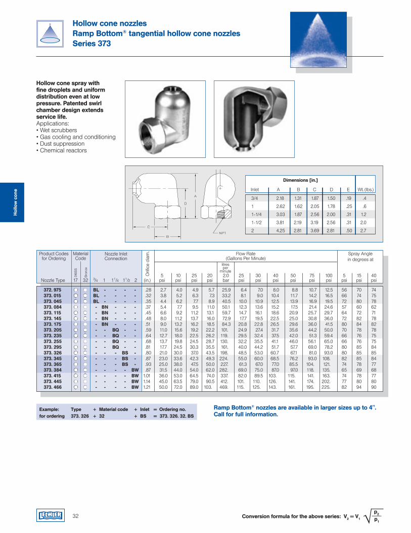
Hollow cone nozzlesRamp Bottom® tangential hollow cone nozzlesSeries 373
Hollow cone spray with fine droplets and uniform distribution even at low pressure. Patented swirl chamber design extends service life.Applications:• Wet scrubbers• Gas cooling and conditioning• Dust suppression• Chemical reactors
Example: Type + Material code + Inlet = Ordering no.for ordering 373. 326 + 32 + BS = 373. 326. 32. BS
Product Codesfor Ordering
Flow Rate(Gallons Per Minute)
Spray Anglein degrees at
5 10 25 20 2.0 25 30 40 50 75 100 5 15 40 Nozzle Type 3/4 1 11/4 11/2 2 (in.) psi psi psi psi bar psi psi psi psi psi psi psi psi psi
MaterialCode
316S
S
Bro
nze
17 32
Conversion formula for the above series: V2 = V1 √ p2
p1
litresper
minute
Nozzle InletConnection
Orifi
ce d
iam
.
Inlet A B C D E Wt. (lbs.)
Dimensions [in.]
3/4 2.18 1.31 1.87 1.50 .19 .4
1 2.62 1.62 2.05 1.78 .25 .6
1-1/4 3.03 1.87 2.56 2.00 .31 1.2
1-1/2 3.81 2.19 3.19 2.56 .31 2.0
2 4.25 2.81 3.69 2.81 .50 2.7
Ramp Bottom® nozzles are available in larger sizes up to 4". Call for full information.
Hol
low
con
e
372. 975 BL - - - - .28 2.7 4.0 4.9 5.7 25.9 6.4 7.0 8.0 8.8 10.7 12.5 56 70 74 373. 015 BL - - - - .32 3.8 5.2 6.3 7.3 33.2 8.1 9.0 10.4 11.7 14.2 16.5 66 74 75 373. 045 BL - - - - .35 4.4 6.2 7.7 8.9 40.5 10.0 10.9 12.5 13.9 16.9 19.5 72 80 78 373. 084 - BN - - - .37 5.4 7.7 9.5 11.0 50.1 12.3 13.6 15.2 17.5 21.4 24.6 57 60 62 373. 115 - BN - - - .45 6.6 9.2 11.2 13.1 59.7 14.7 16.1 18.6 20.9 25.7 29.7 64 72 71 373. 145 - BN - - - .48 8.0 11.2 13.7 16.0 72.9 17.7 19.5 22.5 25.0 30.8 36.0 72 82 78 373. 175 - BN - - - .51 9.0 13.2 16.2 18.5 84.3 20.8 22.8 26.5 29.6 36.0 41.5 80 84 82 373. 205 - - BQ - - .59 11.0 15.6 19.2 22.2 101. 24.9 27.4 31.7 35.6 44.2 50.0 70 78 78 373. 235 - - BQ - - .64 12.7 18.0 22.5 26.2 119. 29.5 32.4 37.5 42.0 51.3 59.4 66 76 75 373. 255 - - BQ - - .68 13.7 19.8 24.5 28.7 130. 32.2 35.5 41.1 46.0 56.1 65.0 66 76 75 373. 295 - - BQ - - .81 17.7 24.5 30.3 35.5 161. 40.0 44.2 51.7 57.7 69.0 78.2 80 85 84 373. 326 - - - BS - .80 21.0 30.0 37.0 43.5 198. 48.5 53.0 60.7 67.1 81.0 93.0 80 85 85 373. 345 - - - BS - .87 23.0 33.6 42.3 49.3 224. 55.0 60.0 68.5 76.2 93.0 108. 82 85 84 373. 365 - - - BS - .93 25.0 38.0 47.5 50.0 227. 61.3 67.0 77.0 85.5 104. 121. 74 78 77 373. 384 - - - - BW .87 31.5 44.0 54.0 62.0 282. 69.0 75.0 87.0 97.0 118. 135. 65 69 68 373. 415 - - - - BW 1.01 36.0 53.0 64.5 74.0 337. 82.0 89.5 103. 115. 141. 163. 74 78 77 373. 445 - - - - BW 1.14 45.0 63.5 79.0 90.5 412. 101. 110. 126. 141. 174. 202. 77 80 80 373. 466 - - - - BW 1.21 50.0 72.0 89.0 103. 469. 115. 125. 143. 161. 195. 225. 82 94 90
33
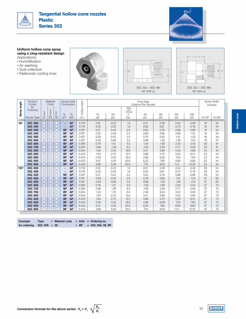
Tangential hollow cone nozzlesPlasticSeries 302
Uniform hollow cone spray using a clog-resistant designApplications:• Humidification• Air washing• Dust collectors• Pasteurizer cooling lines
Example: Type + Material code + Inlet = Ordering no.for ordering 302. 566 + 5E + BF = 302. 566. 5E. BF
ProductCodes
for Ordering
Flow Rate(Gallons Per Minute)
Spray Width(inches)
3/8 3/8 10 20 2 40 60 80 100 Nozzle Type NPT BSP (in.) psi psi bar psi psi psi psi H=10" H=20"
MaterialCode
Nyl
on
Poly
pro.
51 53 5E
Conversion formula for the above series: V2 = V1 √ p2
p1
litresper
minute
Nozzle Inlet Connection
Orifi
ce d
iam
.
Spr
ay a
ngle
PVD
F
90o 302. 406 - AF 0.178 0.16 0.22 1.0 0.31 0.38 0.44 0.49 16 34 302. 486 - AF 0.178 0.25 0.35 1.6 0.50 0.61 0.70 0.78 16 34 302. 526 BF AF 0.197 0.31 0.44 2.0 0.62 0.76 0.88 0.98 16 34 302. 546 BF AF 0.197 0.35 0.49 2.2 0.69 0.85 0.99 1.10 16 34 302. 566 BF AF 0.197 0.39 0.55 2.5 0.78 0.95 1.10 1.23 16 34 302. 606 BF AF 0.197 0.49 0.69 3.2 0.98 1.20 1.39 1.54 18 37 302. 686 BF AF 0.295 0.78 1.10 5.0 1.55 1.90 2.20 2.45 20 41 302. 726 BF AF 0.295 0.98 1.39 6.3 1.95 2.39 2.77 3.09 20 41 302. 806 BF AF 0.354 1.55 2.20 10.0 3.10 3.80 4.40 4.90 22 44 302. 846 BF AF 0.433 1.94 2.75 12.5 3.88 4.75 5.50 6.13 22 44 302. 886 BF AF 0.433 2.48 3.52 16.0 4.96 6.08 7.04 7.84 22 44 302. 926 BF AF 0.433 3.10 4.40 20.0 6.20 7.60 8.80 9.80 22 44 302. 966 BF AF 0.433 3.88 5.50 25.0 7.75 9.50 11.0 12.25 22 44 130o 302. 408 - AF 0.178 0.16 0.22 1.0 0.31 0.38 0.44 0.49 28 54 302. 488 - AF 0.178 0.25 0.35 1.6 0.50 0.61 0.70 0.78 28 54 302. 528 BF AF 0.197 0.31 0.44 2.0 0.62 0.76 0.88 0.98 28 54 302. 568 BF AF 0.197 0.39 0.55 2.5 0.78 0.95 1.10 1.23 31 60 302. 608 BF AF 0.197 0.49 0.69 3.2 0.98 1.20 1.39 1.54 31 60 302. 688 BF AF 0.295 0.78 1.10 5.0 1.55 1.90 2.20 2.45 37 73 302. 728 BF AF 0.295 0.98 1.39 6.3 1.95 2.39 2.77 3.09 37 73 302. 768 BF AF 0.354 1.24 1.76 8.0 2.48 3.04 3.52 3.92 37 73 302. 808 BF AF 0.354 1.55 2.20 10.0 3.10 3.80 4.40 4.90 37 73 302. 848 BF AF 0.433 1.94 2.75 12.5 3.88 4.75 5.50 6.13 37 73 302. 888 BF AF 0.433 2.48 3.52 16.0 4.96 6.08 7.04 7.84 37 73 302. 928 BF AF 0.433 3.10 4.40 20.0 6.20 7.60 8.80 9.80 37 73 302. 968 BF AF 0.433 3.88 5.50 25.0 7.75 9.50 11.0 12.25 37 73
302. 32x – 302. 48xWt: 0.46 oz.
302. 52x – 302. 96xWt: 0.64 oz.
Hol
low
con
e
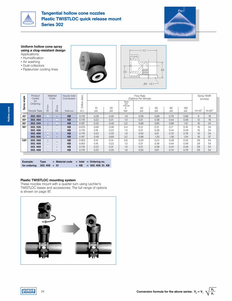
Tangential hollow cone nozzlesPlastic TWISTLOC quick release mountSeries 302
Uniform hollow cone spray using a clog-resistant designApplications:• Humidification• Air washing• Dust collectors• Pasteurizer cooling lines
Example: Type + Material code + Inlet = Ordering no.for ordering 302. 408 + 51 + KB = 302. 408. 51. KB
ProductCodes
for Ordering
Flow Rate(Gallons Per Minute)
Spray Width(inches)
10 20 2 40 60 80 100 Nozzle Type Twist-Loc (in.) psi psi bar psi psi psi psi H=10" H=20"
MaterialCode
Nyl
on
POM
51 56
litresper
minute
Nozzle InletConnection
Orifi
ce d
iam
.
Spr
ay a
ngle
Plastic TWISTLOC mounting systemThese nozzles mount with a quarter turn using Lechler’s TWISTLOC bases and accessories. The full range of options is shown on page 97.
Conversion formula for the above series: V2 = V1 √ p2
p1
Hol
low
con
e
45o 302. 503 - KB 0.178 0.28 0.40 1.8 0.56 0.68 0.79 0.88 9 18 60o 302. 464 - KB 0.178 0.22 0.31 1.0 0.31 0.38 0.44 0.49 12 18 80o 302. 545 - KB 0.197 0.35 0.49 2.2 0.69 0.85 0.99 1.10 16 34 90o 302. 326 KB 0.055 0.06 0.08 0.4 0.12 0.15 0.17 0.19 16 34 302. 406 KB 0.178 0.16 0.22 1.0 0.31 0.38 0.44 0.49 16 34 302. 486 - KB 0.178 0.25 0.35 1.6 0.50 0.61 0.70 0.78 16 34 302. 606 - KB 0.197 0.49 0.69 3.2 0.98 1.20 1.39 1.54 18 37 130o 302. 368 - KB 0.083 0.10 0.14 0.6 0.20 0.24 0.28 0.32 28 54 302. 408 KB 0.083 0.16 0.22 1.0 0.31 0.38 0.44 0.49 28 54 302. 468 - KB 0.178 0.22 0.31 1.0 0.31 0.38 0.44 0.49 28 54 302. 488 - KB 0.178 0.25 0.35 1.6 0.50 0.61 0.70 0.78 28 54
34
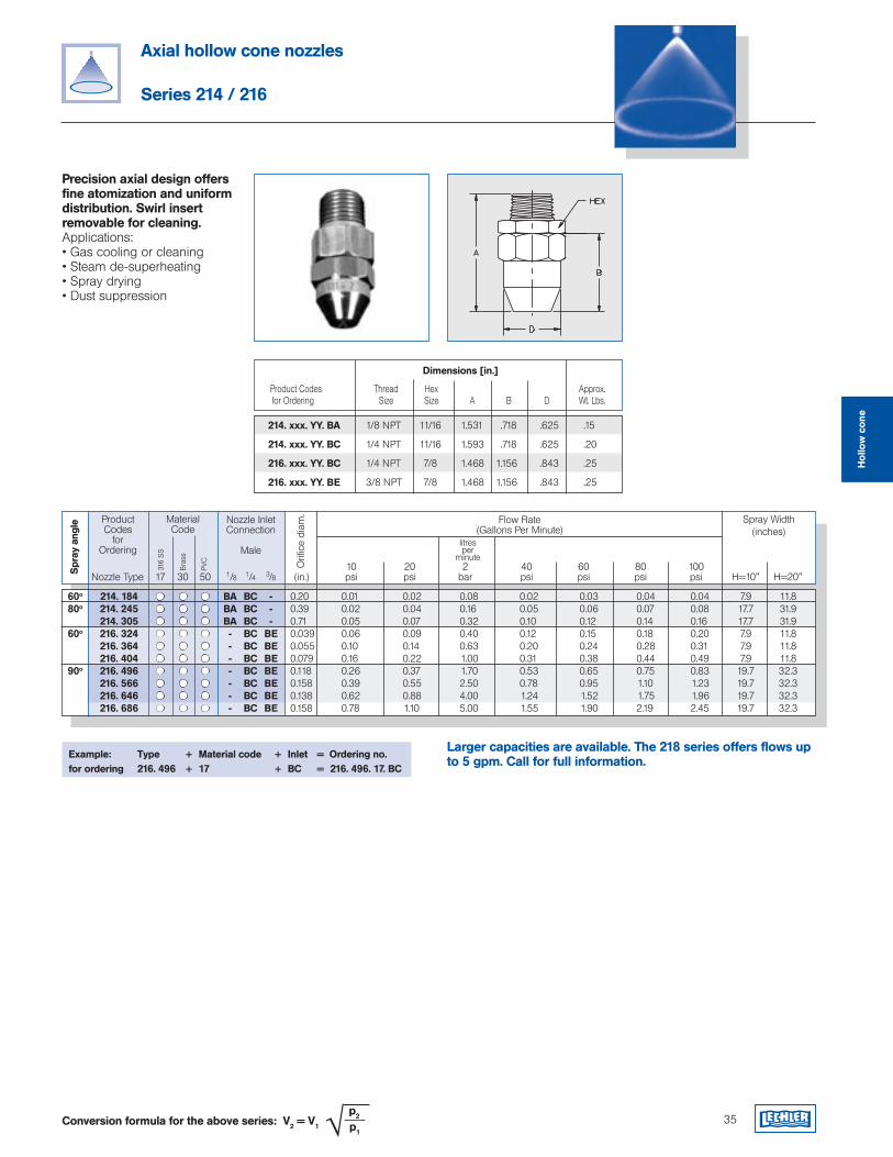
Axial hollow cone nozzles
Series 214 / 216
Precision axial design offers fine atomization and uniform distribution. Swirl insert removable for cleaning.Applications:• Gas cooling or cleaning• Steam de-superheating• Spray drying• Dust suppression
Example: Type + Material code + Inlet = Ordering no.for ordering 216. 496 + 17 + BC = 216. 496. 17. BC
ProductCodes
for Ordering
Flow Rate(Gallons Per Minute)
Spray Width(inches)
10 20 2 40 60 80 100 Nozzle Type 1/8 1/4 3/8 (in.) psi psi bar psi psi psi psi H=10" H=20"
MaterialCode
316
SS
Bra
ss
17 30 50
Conversion formula for the above series: V2 = V1 √ p2
p1
litresper
minute
Nozzle Inlet Connection
Male
Orifi
ce d
iam
.
Spr
ay a
ngle
PVC
60o 214. 184 BA BC - 0.20 0.01 0.02 0.08 0.02 0.03 0.04 0.04 7.9 11.8 80o 214. 245 BA BC - 0.39 0.02 0.04 0.16 0.05 0.06 0.07 0.08 17.7 31.9 214. 305 BA BC - 0.71 0.05 0.07 0.32 0.10 0.12 0.14 0.16 17.7 31.9 60o 216. 324 - BC BE 0.039 0.06 0.09 0.40 0.12 0.15 0.18 0.20 7.9 11.8 216. 364 - BC BE 0.055 0.10 0.14 0.63 0.20 0.24 0.28 0.31 7.9 11.8 216. 404 - BC BE 0.079 0.16 0.22 1.00 0.31 0.38 0.44 0.49 7.9 11.8 90o 216. 496 - BC BE 0.118 0.26 0.37 1.70 0.53 0.65 0.75 0.83 19.7 32.3 216. 566 - BC BE 0.158 0.39 0.55 2.50 0.78 0.95 1.10 1.23 19.7 32.3 216. 646 - BC BE 0.138 0.62 0.88 4.00 1.24 1.52 1.75 1.96 19.7 32.3 216. 686 - BC BE 0.158 0.78 1.10 5.00 1.55 1.90 2.19 2.45 19.7 32.3
35
Product Codes Thread Hex Approx. for Ordering Size Size A B D Wt. Lbs.
Dimensions [in.]
214. xxx. YY. BA 1/8 NPT 11/16 1.531 .718 .625 .15
214. xxx. YY. BC 1/4 NPT 11/16 1.593 .718 .625 .20
216. xxx. YY. BC 1/4 NPT 7/8 1.468 1.156 .843 .25
216. xxx. YY. BE 3/8 NPT 7/8 1.468 1.156 .843 .25
Larger capacities are available. The 218 series offers flows up to 5 gpm. Call for full information.
Hol
low
con
e
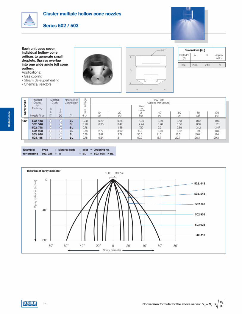
ProductCodes
for Ordering
Flow Rate(Gallons Per Minute)
10 20 2 40 60 80 100 Nozzle Type 3/4 (in.) psi psi bar psi psi psi psi
MaterialCode
316
SS
Bra
ss
17 30
litresper
minute
Nozzle Inlet Connection
Free
Pas
sage
Spr
ay a
ngle
130o 502. 448 BL 0.20 0.20 0.28 1.25 0.39 0.48 0.55 0.62 502. 548 BL 0.20 0.35 0.49 2.24 0.70 0.86 0.99 1.11 502. 748 BL 0.78 - 1.55 7.10 2.21 2.69 3.12 3.47 502. 908 BL 0.78 2.77 3.92 18.0 5.60 6.82 7.90 8.80 503. 028 BL 0.78 5.47 7.74 35.5 11.0 13.5 15.6 17.4 503. 118 BL 0.78 9.24 13.1 60.0 18.7 22.7 26.3 29.3
Cluster multiple hollow cone nozzles
Series 502 / 503
Each unit uses seven individual hollow cone orifices to generate small droplets. Sprays overlap into one wide angle full cone pattern.Applications:• Gas cooling• Steam de-superheating• Chemical reactors
Example: Type + Material code + Inlet = Ordering no.for ordering 503. 028 + 17 + BL = 503. 028. 17. BL
36 Conversion formula for the above series: V2 = V1 √ p2
p1
Inlet NPT A B Approx. (F) Wt lbs.
Dimensions [in.]
3/4 2.36 2.10 .9
Diagram of spray diameter
Spr
ay d
ista
nce
(inch
es)
Spray diameter
502. 448
502. 548
502.748
502.908
503.028
503.118
130o 30 psi
Hol
low
con
e
Full cone nozzlesAbsorptionChemical process engineeringChlorine precipitationCleaningCoolingDesuperheatingDust controlFire protectionFoam controlGas treatmentSpraying onto mats in air washersSpraying over packingsSurface sprayingWater treatmentand many others...
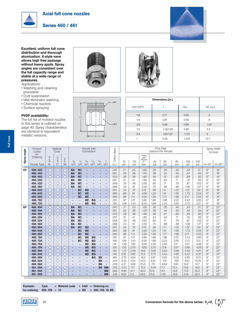
38
Axial full cone nozzles
Series 460 / 461
Excellent, uniform full cone distribution and thorough atomization. X-style vane allows high free passage without heavy spots. Spray angles are consistent over the full capacity range and stable at a wide range of pressures.Applications:• Washing and cleaning processes• Dust suppression• Mist eliminator washing• Chemical reactors• Surface spraying
PVDF availability:The full list of molded nozzles in this series is outlined on page 40. Spray characteristics are identical to equivalent metallic versions.
Example: Type + Material code + Inlet = Ordering no.for ordering 460. 728 + 16 + BE = 460. 728. 16. BE
Inlet (NPT) L Hex Wt. (oz.)
ProductCodes
for Ordering
Flow Rate(Gallons Per Minute)
Spray Width(inches)
1/8 1/4 3/8 1/2 3/4 1 10 20 2 40 60 80 100 150 Nozzle Type 16 17 30 NPT NPT NPT NPT NPT NPT (in.) psi psi bar psi psi psi psi psi H=10" H=20"
MaterialCode
303
SS
316
SS
litresper
minute
Nozzle Inlet Connection
Orifi
ce d
iam
.
Spr
ay a
ngle
Bra
ss
Dimensions [in.]
1/8 0.71 0.56 .5
1/4 0.87 0.56 .6
3/8 0.96 0.69 1.06
1/2 1.28/1.65 0.88 2.3
3/4 1.65/1.97 1.125 6
1 2.20 1.375 12.7
Conversion formula for the above series: V2=V1P2
0.4
P1
( )
Full
cone
45o 460. 403 BA BC - - - - .047 .17 .23 1.00 .30 .35 .40 .43 .51 6" 16" 460. 443 BA BC - - - - .051 .22 .28 1.25 .38 .44 .50 .54 .64 6" 16" 460. 483 BA BC - - - - .053 .28 .36 1.60 .48 .57 .63 .69 .82 6" 16" 460. 503 BA BC - - - - .057 .31 .41 1.80 .54 .64 .71 .78 .92 6" 16" 460. 523 BA BC - - - - .059 .35 .46 2.00 .60 .71 .79 .87 1.02 6" 16" 460. 563 BA BC - - - - .066 .43 .57 2.50 .75 .88 .99 1.08 1.27 6" 16" 460. 603 - BC BE - - - .074 .54 .72 3.15 .95 1.11 1.25 1.37 1.61 6" 16" 460. 643 - BC BE - - - .084 .69 .91 4.00 1.20 1.41 1.59 1.73 2.04 6" 16" 460. 683 - BC BE - - - .094 .86 1.14 5.00 1.50 1.77 1.98 2.17 2.55 6" 16" 460. 703 - - BE BG - - .100 .97 1.27 5.60 1.68 1.98 2.22 2.43 2.85 6" 16" 460. 723 - - BE BG - - .106 1.09 1.43 6.30 1.89 2.23 2.50 2.73 3.21 6" 16" 60o 460. 404 BA BC - - - - .047 .17 .23 1.00 .30 .35 .40 .43 .51 9" 22" 460. 444 BA BC - - - - .051 .22 .28 1.25 .38 .44 .50 .54 .64 9" 22" 460. 484 BA BC - - - - .053 .28 .36 1.60 .48 .57 .63 .69 .82 9" 22" 460. 504 BA BC - - - - .057 .31 .41 1.80 .54 .64 .71 .78 .92 9" 22" 460. 524 BA BC - - - - .059 .35 .46 2.00 .60 .71 .79 .87 1.02 9" 22" 460. 564 BA BC - - - - .066 .43 .57 2.50 .75 .88 .99 1.08 1.27 9" 22" 460. 604 BA BC BE - - - .074 .54 .72 3.15 .95 1.11 1.25 1.37 1.61 9" 22" 460. 644 - BC BE - - - .084 .69 .91 4.00 1.20 1.41 1.59 1.73 2.04 9" 22" 460. 684 - BC BE - - - .094 .86 1.14 5.00 1.50 1.77 1.98 2.17 2.55 9" 22" 460. 704 - BC BE BG - - .100 .97 1.27 5.60 1.68 1.98 2.22 2.43 2.85 9" 22" 460. 724 - BC BE BG - - .106 1.09 1.43 6.30 1.89 2.23 2.50 2.73 3.21 9" 22" 460. 764 - - BE BG - - .116 1.38 1.82 8.00 2.40 2.83 3.17 3.47 4.08 9" 22" 460. 784 - - BE BG - - .126 1.55 2.05 9.00 2.70 3.18 3.57 3.90 4.59 9" 22" 460. 804 - - BE BG - - .133 1.73 2.28 10.0 3.00 3.53 3.96 4.33 5.10 9" 22" 460. 844 - - BE BG - - .149 2.16 2.85 12.5 3.75 4.42 4.95 5.42 6.37 9" 22" 460. 884 - - - BG BK - .169 2.76 3.64 16.0 4.81 5.65 6.34 6.93 8.15 9" 22" 460. 924 - - - - BK - .204 3.45 4.55 20.0 6.01 7.07 7.93 8.67 10.19 9" 22" 460. 964 - - - - BK - .228 4.31 5.69 25.0 7.51 8.83 9.91 10.8 12.7 9" 22" 461. 004 - - - - BK BM .252 5.43 7.17 31.5 9.46 11.1 12.4 13.6 16.0 9" 22" 461. 044 - - - - - BM .283 6.90 9.11 40.0 12.0 14.1 15.8 17.3 20.3 9" 22" 461. 084 - - - - - BM .338 8.63 11.3 50.0 15.0 17.6 19.8 21.6 25.4 9" 22"
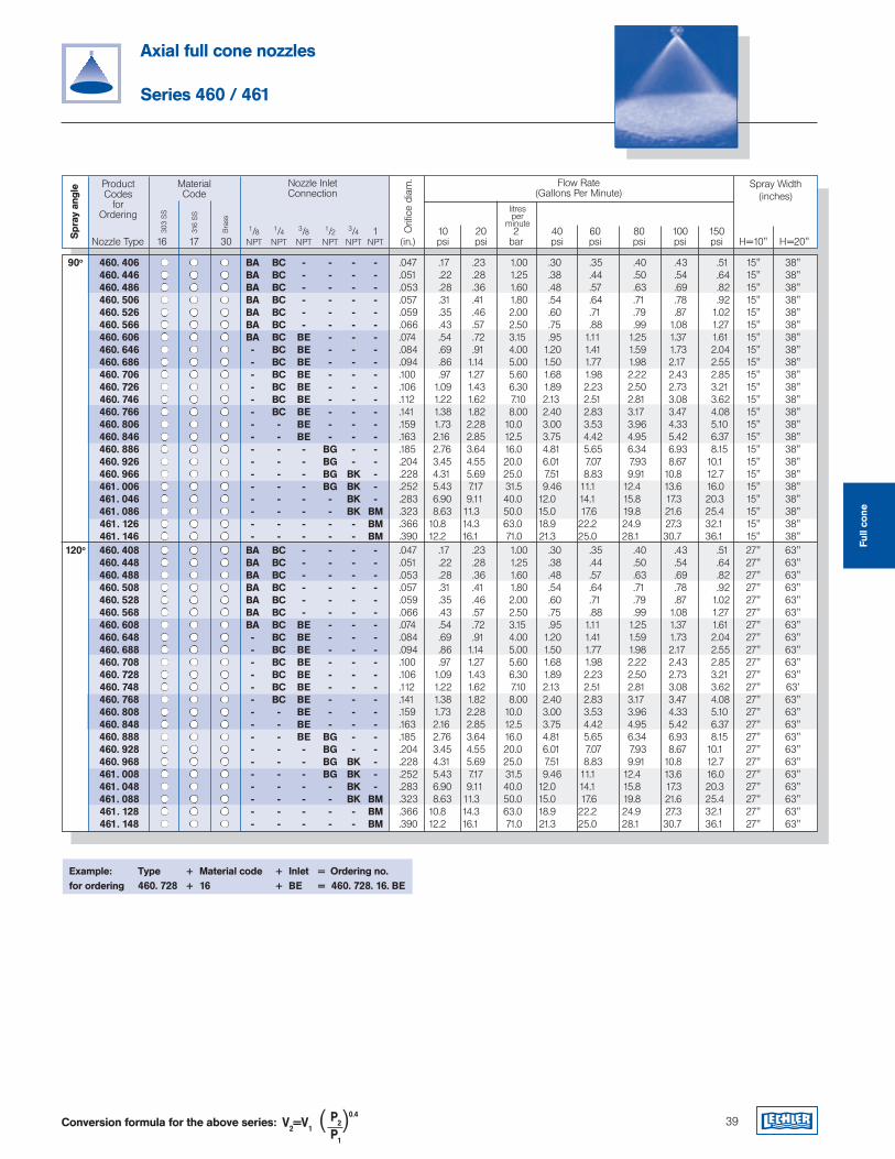
39
Axial full cone nozzles
Series 460 / 461
Example: Type + Material code + Inlet = Ordering no.for ordering 460. 728 + 16 + BE = 460. 728. 16. BE
ProductCodes
for Ordering
Flow Rate(Gallons Per Minute)
Spray Width(inches)
1/8 1/4 3/8 1/2 3/4 1 10 20 2 40 60 80 100 150 Nozzle Type 16 17 30 NPT NPT NPT NPT NPT NPT (in.) psi psi bar psi psi psi psi psi H=10" H=20"
MaterialCode
303
SS
316
SS litres
per minute
Nozzle Inlet Connection
Orifi
ce d
iam
.
Spr
ay a
ngle
Bra
ss
Conversion formula for the above series: V2=V1P2
0.4
P1
( )
90o 460. 406 BA BC - - - - .047 .17 .23 1.00 .30 .35 .40 .43 .51 15" 38" 460. 446 BA BC - - - - .051 .22 .28 1.25 .38 .44 .50 .54 .64 15" 38" 460. 486 BA BC - - - - .053 .28 .36 1.60 .48 .57 .63 .69 .82 15" 38" 460. 506 BA BC - - - - .057 .31 .41 1.80 .54 .64 .71 .78 .92 15" 38" 460. 526 BA BC - - - - .059 .35 .46 2.00 .60 .71 .79 .87 1.02 15" 38" 460. 566 BA BC - - - - .066 .43 .57 2.50 .75 .88 .99 1.08 1.27 15" 38" 460. 606 BA BC BE - - - .074 .54 .72 3.15 .95 1.11 1.25 1.37 1.61 15" 38" 460. 646 - BC BE - - - .084 .69 .91 4.00 1.20 1.41 1.59 1.73 2.04 15" 38" 460. 686 - BC BE - - - .094 .86 1.14 5.00 1.50 1.77 1.98 2.17 2.55 15" 38" 460. 706 - BC BE - - - .100 .97 1.27 5.60 1.68 1.98 2.22 2.43 2.85 15" 38" 460. 726 - BC BE - - - .106 1.09 1.43 6.30 1.89 2.23 2.50 2.73 3.21 15" 38" 460. 746 - BC BE - - - .112 1.22 1.62 7.10 2.13 2.51 2.81 3.08 3.62 15" 38" 460. 766 - BC BE - - - .141 1.38 1.82 8.00 2.40 2.83 3.17 3.47 4.08 15" 38" 460. 806 - - BE - - - .159 1.73 2.28 10.0 3.00 3.53 3.96 4.33 5.10 15" 38" 460. 846 - - BE - - - .163 2.16 2.85 12.5 3.75 4.42 4.95 5.42 6.37 15" 38" 460. 886 - - - BG - - .185 2.76 3.64 16.0 4.81 5.65 6.34 6.93 8.15 15" 38" 460. 926 - - - BG - - .204 3.45 4.55 20.0 6.01 7.07 7.93 8.67 10.1 15" 38" 460. 966 - - - BG BK - .228 4.31 5.69 25.0 7.51 8.83 9.91 10.8 12.7 15" 38" 461. 006 - - - BG BK - .252 5.43 7.17 31.5 9.46 11.1 12.4 13.6 16.0 15" 38" 461. 046 - - - - BK - .283 6.90 9.11 40.0 12.0 14.1 15.8 17.3 20.3 15" 38" 461. 086 - - - - BK BM .323 8.63 11.3 50.0 15.0 17.6 19.8 21.6 25.4 15" 38" 461. 126 - - - - - BM .366 10.8 14.3 63.0 18.9 22.2 24.9 27.3 32.1 15" 38" 461. 146 - - - - - BM .390 12.2 16.1 71.0 21.3 25.0 28.1 30.7 36.1 15" 38" 120o 460. 408 BA BC - - - - .047 .17 .23 1.00 .30 .35 .40 .43 .51 27" 63" 460. 448 BA BC - - - - .051 .22 .28 1.25 .38 .44 .50 .54 .64 27" 63" 460. 488 BA BC - - - - .053 .28 .36 1.60 .48 .57 .63 .69 .82 27" 63" 460. 508 BA BC - - - - .057 .31 .41 1.80 .54 .64 .71 .78 .92 27" 63" 460. 528 BA BC - - - - .059 .35 .46 2.00 .60 .71 .79 .87 1.02 27" 63" 460. 568 BA BC - - - - .066 .43 .57 2.50 .75 .88 .99 1.08 1.27 27" 63" 460. 608 BA BC BE - - - .074 .54 .72 3.15 .95 1.11 1.25 1.37 1.61 27" 63" 460. 648 - BC BE - - - .084 .69 .91 4.00 1.20 1.41 1.59 1.73 2.04 27" 63" 460. 688 - BC BE - - - .094 .86 1.14 5.00 1.50 1.77 1.98 2.17 2.55 27" 63" 460. 708 - BC BE - - - .100 .97 1.27 5.60 1.68 1.98 2.22 2.43 2.85 27" 63" 460. 728 - BC BE - - - .106 1.09 1.43 6.30 1.89 2.23 2.50 2.73 3.21 27" 63" 460. 748 - BC BE - - - .112 1.22 1.62 7.10 2.13 2.51 2.81 3.08 3.62 27" 63' 460. 768 - BC BE - - - .141 1.38 1.82 8.00 2.40 2.83 3.17 3.47 4.08 27" 63" 460. 808 - - BE - - - .159 1.73 2.28 10.0 3.00 3.53 3.96 4.33 5.10 27" 63" 460. 848 - - BE - - - .163 2.16 2.85 12.5 3.75 4.42 4.95 5.42 6.37 27" 63" 460. 888 - - BE BG - - .185 2.76 3.64 16.0 4.81 5.65 6.34 6.93 8.15 27" 63" 460. 928 - - - BG - - .204 3.45 4.55 20.0 6.01 7.07 7.93 8.67 10.1 27" 63" 460. 968 - - - BG BK - .228 4.31 5.69 25.0 7.51 8.83 9.91 10.8 12.7 27" 63" 461. 008 - - - BG BK - .252 5.43 7.17 31.5 9.46 11.1 12.4 13.6 16.0 27" 63" 461. 048 - - - - BK - .283 6.90 9.11 40.0 12.0 14.1 15.8 17.3 20.3 27" 63" 461. 088 - - - - BK BM .323 8.63 11.3 50.0 15.0 17.6 19.8 21.6 25.4 27" 63" 461. 128 - - - - - BM .366 10.8 14.3 63.0 18.9 22.2 24.9 27.3 32.1 27" 63" 461. 148 - - - - - BM .390 12.2 16.1 71.0 21.3 25.0 28.1 30.7 36.1 27" 63"
Full
cone
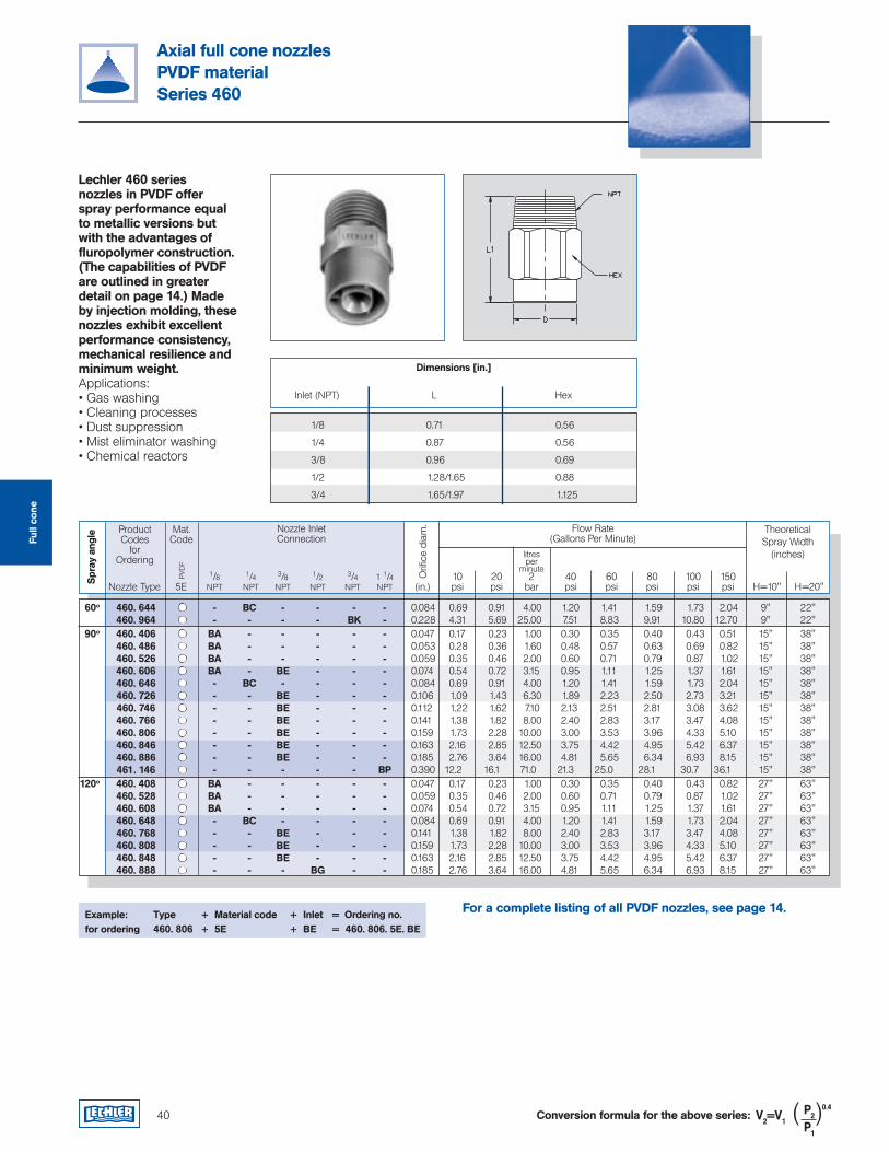
1/8 0.71 0.56
1/4 0.87 0.56
3/8 0.96 0.69
1/2 1.28/1.65 0.88
3/4 1.65/1.97 1.125
Axial full cone nozzlesPVDF materialSeries 460
Lechler 460 series nozzles in PVDF offer spray performance equal to metallic versions but with the advantages of fluropolymer construction. (The capabilities of PVDF are outlined in greater detail on page 14.) Made by injection molding, these nozzles exhibit excellent performance consistency, mechanical resilience and minimum weight. Applications:• Gas washing• Cleaning processes• Dust suppression• Mist eliminator washing• Chemical reactors
Example: Type + Material code + Inlet = Ordering no.for ordering 460. 806 + 5E + BE = 460. 806. 5E. BE
Inlet (NPT) L Hex
ProductCodes
for Ordering
Flow Rate(Gallons Per Minute)
TheoreticalSpray Width
(inches)
1/8 1/4 3/8 1/2 3/4 1 1/4 10 20 2 40 60 80 100 150 Nozzle Type 5E NPT NPT NPT NPT NPT NPT (in.) psi psi bar psi psi psi psi psi H=10" H=20"
Mat.Code
PVD
F
litresper
minute
Nozzle Inlet Connection
Orifi
ce d
iam
.
Spr
ay a
ngle
Dimensions [in.]
Conversion formula for the above series: V2=V1P2
0.4
P1
( )
For a complete listing of all PVDF nozzles, see page 14.
Full
cone
60o 460. 644 - BC - - - - 0.084 0.69 0.91 4.00 1.20 1.41 1.59 1.73 2.04 9" 22" 460. 964 - - - - BK - 0.228 4.31 5.69 25.00 7.51 8.83 9.91 10.80 12.70 9" 22" 90o 460. 406 BA - - - - - 0.047 0.17 0.23 1.00 0.30 0.35 0.40 0.43 0.51 15" 38" 460. 486 BA - - - - - 0.053 0.28 0.36 1.60 0.48 0.57 0.63 0.69 0.82 15" 38" 460. 526 BA - - - - - 0.059 0.35 0.46 2.00 0.60 0.71 0.79 0.87 1.02 15" 38" 460. 606 BA - BE - - - 0.074 0.54 0.72 3.15 0.95 1.11 1.25 1.37 1.61 15" 38" 460. 646 - BC - - - - 0.084 0.69 0.91 4.00 1.20 1.41 1.59 1.73 2.04 15" 38" 460. 726 - - BE - - - 0.106 1.09 1.43 6.30 1.89 2.23 2.50 2.73 3.21 15" 38" 460. 746 - - BE - - - 0.112 1.22 1.62 7.10 2.13 2.51 2.81 3.08 3.62 15" 38" 460. 766 - - BE - - - 0.141 1.38 1.82 8.00 2.40 2.83 3.17 3.47 4.08 15" 38" 460. 806 - - BE - - - 0.159 1.73 2.28 10.00 3.00 3.53 3.96 4.33 5.10 15" 38" 460. 846 - - BE - - - 0.163 2.16 2.85 12.50 3.75 4.42 4.95 5.42 6.37 15" 38" 460. 886 - - BE - - - 0.185 2.76 3.64 16.00 4.81 5.65 6.34 6.93 8.15 15" 38" 461. 146 - - - - - BP 0.390 12.2 16.1 71.0 21.3 25.0 28.1 30.7 36.1 15" 38" 120o 460. 408 BA - - - - - 0.047 0.17 0.23 1.00 0.30 0.35 0.40 0.43 0.82 27" 63" 460. 528 BA - - - - - 0.059 0.35 0.46 2.00 0.60 0.71 0.79 0.87 1.02 27" 63" 460. 608 BA - - - - - 0.074 0.54 0.72 3.15 0.95 1.11 1.25 1.37 1.61 27" 63" 460. 648 - BC - - - - 0.084 0.69 0.91 4.00 1.20 1.41 1.59 1.73 2.04 27" 63" 460. 768 - - BE - - - 0.141 1.38 1.82 8.00 2.40 2.83 3.17 3.47 4.08 27" 63" 460. 808 - - BE - - - 0.159 1.73 2.28 10.00 3.00 3.53 3.96 4.33 5.10 27" 63" 460. 848 - - BE - - - 0.163 2.16 2.85 12.50 3.75 4.42 4.95 5.42 6.37 27" 63" 460. 888 - - - BG - - 0.185 2.76 3.64 16.00 4.81 5.65 6.34 6.93 8.15 27" 63"
40
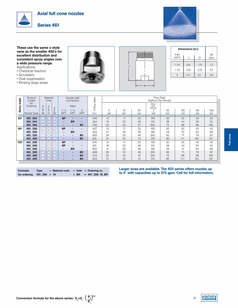
60o 461. 204 BP - - .449 13 17 23 100 30 35 40 43 461. 244 - BR - .504 16 22 28 125 38 44 50 54 461. 364 - - BV .709 33 43 57 250 75 88 99 108 90o 461. 206 BP - - .457 13 17 23 100 30 35 40 43 461. 286 - BR - .583 21 28 36 160 48 57 63 69 461. 326 - - BV .650 26 35 46 200 60 71 79 87 461. 406 - - BV .815 41 54 72 315 95 111 125 137 120o 461. 208 BP - - .476 13 17 23 100 30 35 40 43 461. 248 BP - - .531 16 22 28 125 38 44 50 54 461. 288 - BR - .602 21 28 36 160 48 57 63 69 461. 328 - - BV .669 26 35 46 200 60 71 79 87 461. 368 - - BV .223 33 43 57 250 75 88 99 108 461. 408 - - BV .843 41 54 72 315 95 111 125 137
ProductCodes
for Ordering
Flow Rate(Gallons Per Minute)
MaterialCode
303
SS
316
SS
16 17 30
litresper
minute
Orifi
ce d
iam
.
Spr
ay a
ngle
Bra
ss
Nozzle Inlet Connection
Male
1-1/4 1-1/2 2 5 10 20 2 40 60 80 100 Nozzle Type NPT NPT NPT (in.) psi psi psi bar psi psi psi psi
41
These use the same x-style vane as the smaller 460's for excellent distribution and consistent spray angles over a wide pressure range.Applications:• Chemical reactors• Scrubbers• Dust suppression• Rinsing large areas
Example: Type + Material code + Inlet = Ordering no.for ordering 461. 288 + 16 + BR = 461. 288. 16. BR
Axial full cone nozzles
Series 461
Dimensions [in.]
Conversion formula for the above series: V2=V1P2
0.4
P1
( )
Larger sizes are available. The 403 series offers nozzles up to 4" with capacities up to 375 gpm. Call for full information.
Full
cone
1-1/4 2.91 1.75 1.3
1-1/2 3.34 2.25 2.2
2 4.17 2.5 5.9
L D Inlet(NPT)
Wt.(lbs.)
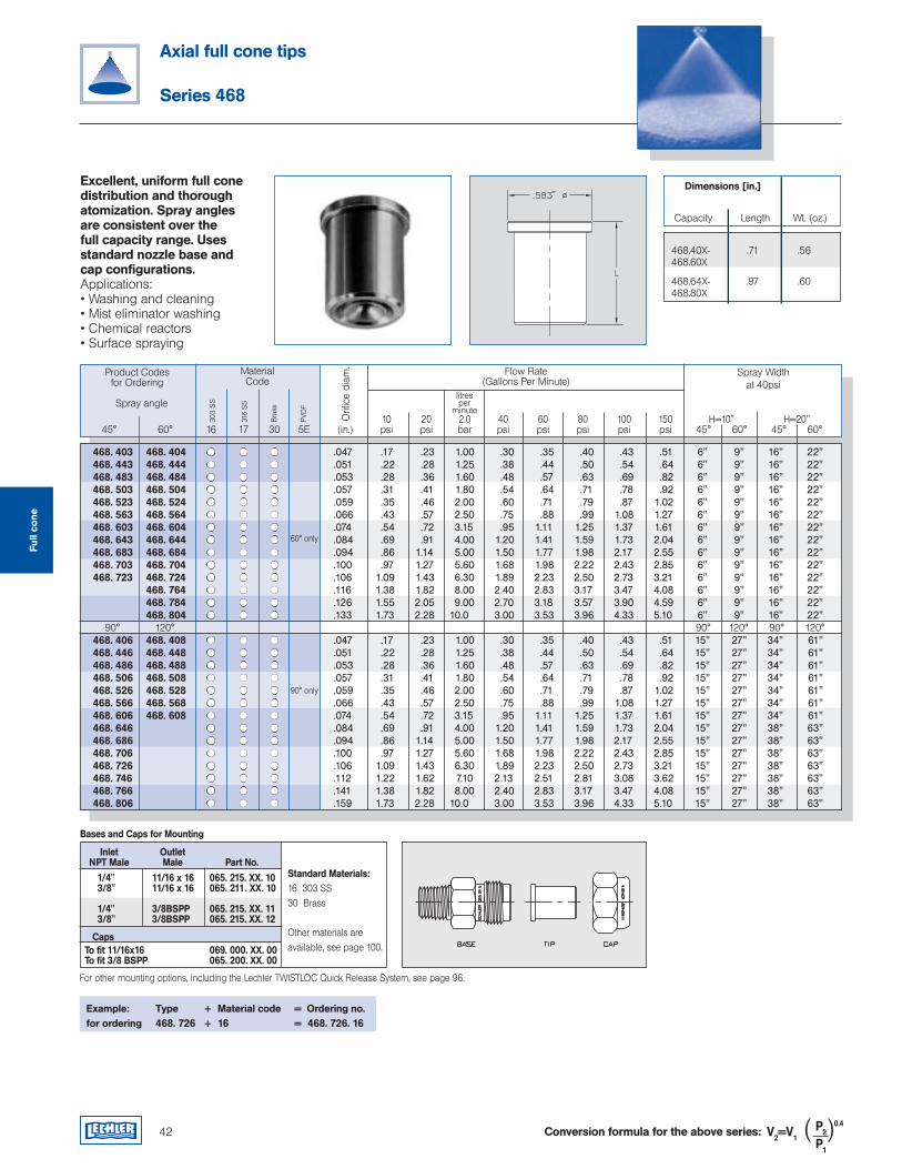
42
Axial full cone tips
Series 468
Excellent, uniform full cone distribution and thorough atomization. Spray angles are consistent over the full capacity range. Uses standard nozzle base and cap configurations.Applications:• Washing and cleaning • Mist eliminator washing• Chemical reactors• Surface spraying
Product Codesfor Ordering
Flow Rate(Gallons Per Minute)
MaterialCode
303
SS
316
SS
litresper
minute
Orifi
ce d
iam
.
Bra
ss
PVD
F
468.40X- .71 .56 468.60X
468.64X- .97 .60 468.80X
Capacity Length Wt. (oz.)
10 20 2.0 40 60 80 100 150 H=10" H=20" 45° 60° 16 17 30 5E (in.) psi psi bar psi psi psi psi psi 45° 60° 45° 60°
Spray angle
Example: Type + Material code = Ordering no.for ordering 468. 726 + 16 = 468. 726. 16
Spray Widthat 40psi
Dimensions [in.]
Conversion formula for the above series: V2=V1P2
0.4
P1
( )
468. 403 468. 404 .047 .17 .23 1.00 .30 .35 .40 .43 .51 6" 9" 16" 22" 468. 443 468. 444 .051 .22 .28 1.25 .38 .44 .50 .54 .64 6" 9" 16" 22" 468. 483 468. 484 .053 .28 .36 1.60 .48 .57 .63 .69 .82 6" 9" 16" 22" 468. 503 468. 504 .057 .31 .41 1.80 .54 .64 .71 .78 .92 6" 9" 16" 22" 468. 523 468. 524 .059 .35 .46 2.00 .60 .71 .79 .87 1.02 6" 9" 16" 22" 468. 563 468. 564 .066 .43 .57 2.50 .75 .88 .99 1.08 1.27 6" 9" 16" 22" 468. 603 468. 604 .074 .54 .72 3.15 .95 1.11 1.25 1.37 1.61 6" 9" 16" 22" 468. 643 468. 644 .084 .69 .91 4.00 1.20 1.41 1.59 1.73 2.04 6" 9" 16" 22" 468. 683 468. 684 .094 .86 1.14 5.00 1.50 1.77 1.98 2.17 2.55 6" 9" 16" 22" 468. 703 468. 704 .100 .97 1.27 5.60 1.68 1.98 2.22 2.43 2.85 6" 9" 16" 22" 468. 723 468. 724 .106 1.09 1.43 6.30 1.89 2.23 2.50 2.73 3.21 6" 9" 16" 22" 468. 764 .116 1.38 1.82 8.00 2.40 2.83 3.17 3.47 4.08 6" 9" 16" 22" 468. 784 .126 1.55 2.05 9.00 2.70 3.18 3.57 3.90 4.59 6" 9" 16" 22" 468. 804 .133 1.73 2.28 10.0 3.00 3.53 3.96 4.33 5.10 6" 9" 16" 22" 90° 120° 90° 120° 90° 120° 468. 406 468. 408 .047 .17 .23 1.00 .30 .35 .40 .43 .51 15" 27" 34" 61" 468. 446 468. 448 .051 .22 .28 1.25 .38 .44 .50 .54 .64 15" 27" 34" 61" 468. 486 468. 488 .053 .28 .36 1.60 .48 .57 .63 .69 .82 15" 27" 34" 61" 468. 506 468. 508 .057 .31 .41 1.80 .54 .64 .71 .78 .92 15" 27" 34" 61" 468. 526 468. 528 .059 .35 .46 2.00 .60 .71 .79 .87 1.02 15" 27" 34" 61" 468. 566 468. 568 .066 .43 .57 2.50 .75 .88 .99 1.08 1.27 15" 27" 34" 61" 468. 606 468. 608 .074 .54 .72 3.15 .95 1.11 1.25 1.37 1.61 15" 27" 34" 61" 468. 646 .084 .69 .91 4.00 1.20 1.41 1.59 1.73 2.04 15" 27" 38" 63" 468. 686 .094 .86 1.14 5.00 1.50 1.77 1.98 2.17 2.55 15" 27" 38" 63" 468. 706 .100 .97 1.27 5.60 1.68 1.98 2.22 2.43 2.85 15" 27" 38" 63" 468. 726 .106 1.09 1.43 6.30 1.89 2.23 2.50 2.73 3.21 15" 27" 38" 63" 468. 746 .112 1.22 1.62 7.10 2.13 2.51 2.81 3.08 3.62 15" 27" 38" 63" 468. 766 .141 1.38 1.82 8.00 2.40 2.83 3.17 3.47 4.08 15" 27" 38" 63" 468. 806 .159 1.73 2.28 10.0 3.00 3.53 3.96 4.33 5.10 15" 27" 38" 63"
1/4" 11/16 x 16 065. 215. XX. 10 3/8" 11/16 x 16 065. 211. XX. 10
1/4" 3/8BSPP 065. 215. XX. 11 3/8" 3/8BSPP 065. 215. XX. 12
To fit 11/16x16 069. 000. XX. 00 To fit 3/8 BSPP 065. 200. XX. 00
Standard Materials:16 303 SS 30 Brass
Other materials are available, see page 100.
Inlet Outlet NPT Male Male Part No.
Bases and Caps for Mounting
Caps
For other mounting options, including the Lechler TWISTLOC Quick Release System, see page 96.
60° only
Full
cone
90° only
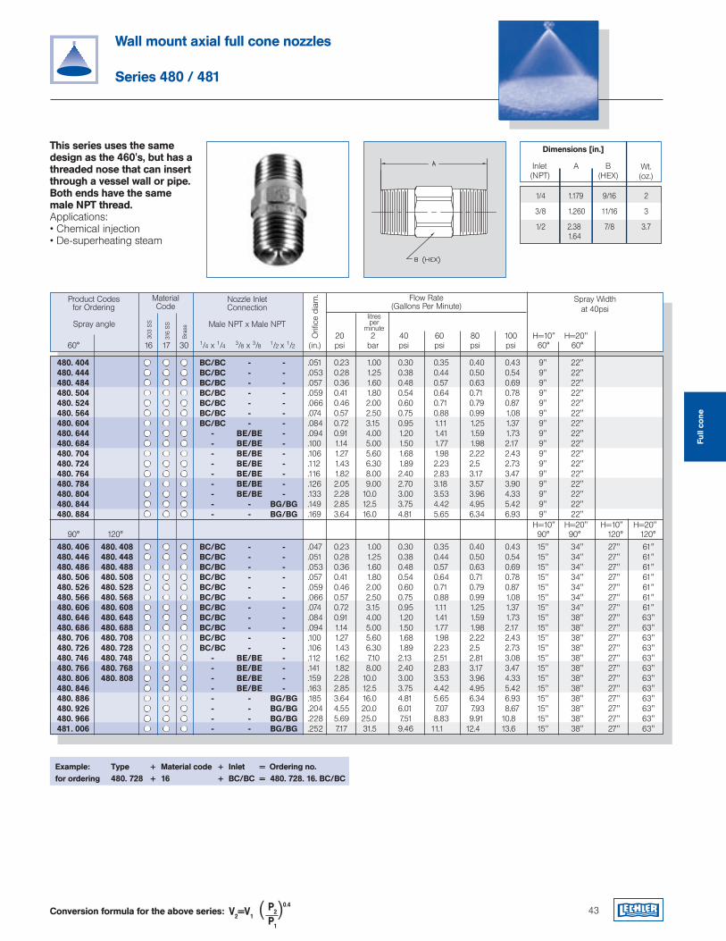
43
Wall mount axial full cone nozzles
Series 480 / 481
This series uses the same design as the 460's, but has a threaded nose that can insert through a vessel wall or pipe. Both ends have the same male NPT thread.Applications:• Chemical injection• De-superheating steam
Example: Type + Material code + Inlet = Ordering no.for ordering 480. 728 + 16 + BC/BC = 480. 728. 16. BC/BC
Product Codesfor Ordering
Flow Rate(Gallons Per Minute)
MaterialCode
303
SS
316
SS
litresper
minute
Orifi
ce d
iam
.
Bra
ssSpray angle
Spray Widthat 40psi
20 2 40 60 80 100 H=10" H=20" 60° 16 17 30 1/4 x 1/4 3/8 x 3/8 1/2 x 1/2 (in.) psi bar psi psi psi psi 60° 60°
Nozzle InletConnection
Male NPT x Male NPT
Dimensions [in.]
A B (HEX)
Inlet(NPT)
Wt.(oz.)
1/4 1.179 9/16 2
3/8 1.260 11/16 3
1/2 2.38 7/8 3.7 1.64
Conversion formula for the above series: V2=V1P2
0.4
P1
( )
Full
cone
H=10" H=20" H=10" H=20" 90° 120° 90° 90° 120° 120°
480. 404 BC/BC - - .051 0.23 1.00 0.30 0.35 0.40 0.43 9" 22" 480. 444 BC/BC - - .053 0.28 1.25 0.38 0.44 0.50 0.54 9" 22" 480. 484 BC/BC - - .057 0.36 1.60 0.48 0.57 0.63 0.69 9" 22" 480. 504 BC/BC - - .059 0.41 1.80 0.54 0.64 0.71 0.78 9" 22" 480. 524 BC/BC - - .066 0.46 2.00 0.60 0.71 0.79 0.87 9" 22" 480. 564 BC/BC - - .074 0.57 2.50 0.75 0.88 0.99 1.08 9" 22" 480. 604 BC/BC - - .084 0.72 3.15 0.95 1.11 1.25 1.37 9" 22" 480. 644 - BE/BE - .094 0.91 4.00 1.20 1.41 1.59 1.73 9" 22" 480. 684 - BE/BE - .100 1.14 5.00 1.50 1.77 1.98 2.17 9" 22" 480. 704 - BE/BE - .106 1.27 5.60 1.68 1.98 2.22 2.43 9" 22" 480. 724 - BE/BE - .112 1.43 6.30 1.89 2.23 2.5 2.73 9" 22" 480. 764 - BE/BE - .116 1.82 8.00 2.40 2.83 3.17 3.47 9" 22" 480. 784 - BE/BE - .126 2.05 9.00 2.70 3.18 3.57 3.90 9" 22" 480. 804 - BE/BE - .133 2.28 10.0 3.00 3.53 3.96 4.33 9" 22" 480. 844 - - BG/BG .149 2.85 12.5 3.75 4.42 4.95 5.42 9" 22" 480. 884 - - BG/BG .169 3.64 16.0 4.81 5.65 6.34 6.93 9" 22"
480. 406 480. 408 BC/BC - - .047 0.23 1.00 0.30 0.35 0.40 0.43 15" 34" 27" 61" 480. 446 480. 448 BC/BC - - .051 0.28 1.25 0.38 0.44 0.50 0.54 15" 34" 27" 61" 480. 486 480. 488 BC/BC - - .053 0.36 1.60 0.48 0.57 0.63 0.69 15" 34" 27" 61" 480. 506 480. 508 BC/BC - - .057 0.41 1.80 0.54 0.64 0.71 0.78 15" 34" 27" 61" 480. 526 480. 528 BC/BC - - .059 0.46 2.00 0.60 0.71 0.79 0.87 15" 34" 27" 61" 480. 566 480. 568 BC/BC - - .066 0.57 2.50 0.75 0.88 0.99 1.08 15" 34" 27" 61" 480. 606 480. 608 BC/BC - - .074 0.72 3.15 0.95 1.11 1.25 1.37 15" 34" 27" 61" 480. 646 480. 648 BC/BC - - .084 0.91 4.00 1.20 1.41 1.59 1.73 15" 38" 27" 63" 480. 686 480. 688 BC/BC - - .094 1.14 5.00 1.50 1.77 1.98 2.17 15" 38" 27" 63" 480. 706 480. 708 BC/BC - - .100 1.27 5.60 1.68 1.98 2.22 2.43 15" 38" 27" 63" 480. 726 480. 728 BC/BC - - .106 1.43 6.30 1.89 2.23 2.5 2.73 15" 38" 27" 63" 480. 746 480. 748 - BE/BE - .112 1.62 7.10 2.13 2.51 2.81 3.08 15" 38" 27" 63" 480. 766 480. 768 - BE/BE - .141 1.82 8.00 2.40 2.83 3.17 3.47 15" 38" 27" 63" 480. 806 480. 808 - BE/BE - .159 2.28 10.0 3.00 3.53 3.96 4.33 15" 38" 27" 63" 480. 846 - BE/BE - .163 2.85 12.5 3.75 4.42 4.95 5.42 15" 38" 27" 63" 480. 886 - - BG/BG .185 3.64 16.0 4.81 5.65 6.34 6.93 15" 38" 27" 63" 480. 926 - - BG/BG .204 4.55 20.0 6.01 7.07 7.93 8.67 15" 38" 27" 63" 480. 966 - - BG/BG .228 5.69 25.0 7.51 8.83 9.91 10.8 15" 38" 27" 63" 481. 006 - - BG/BG .252 7.17 31.5 9.46 11.1 12.4 13.6 15" 38" 27" 63"
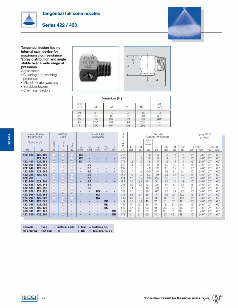
44 Conversion formula for the above series: V2=V1P2
0.4
P1
( )
Tangential full cone nozzles
Series 422 / 423
Tangential design has no internal swirl device for maximum clog resistance. Spray distribution and angle stable over a wide range of pressures.Applications:• Cleaning and washing processes• Mist eliminator washing• Scrubber towers• Chemical reactors
L1 L2 H1 H2 Inlet(NPT)
Wt.(oz.)
Product Codesfor Ordering
Flow Rate(Gallons Per Minute)
MaterialCode
303
SS
316
SS
litresper
minute
Orifi
ce d
iam
.
Bra
ss
Spray angle
Spray Widthat 40psi
1/4 3/8 1/2 3/4 1 10 20 2 40 60 80 100 H=10" H=20" 90° 120° 16 17 30 NPT NPT NPT NPT NPT (in.) psi psi bar psi psi psi psi 90° 120° 90° 120°
Nozzle InletConnection
Example: Type + Material code + Inlet = Ordering no.for ordering 422. 806 + 16 + BE = 422. 806. 16. BE
Dimensions [in.]
1/4 1.1 .79 .31 .81 1.5 3/8 1.42 .98 .43 1.04 3.75 1/2 1.91 1.32 .79 1.52 8.87 3/4 2.30 1.52 .93 2.24 — 1 3.00 1.91 1.08 2.60 —
Full
cone
422. 406 422. 408 BC - - - - .059 .1 .2 1.0 .3 .3 .4 .4 15" 34.6" 27" 60" 422. 448 BC - - - - .065 .1 .2 1.2 .3 .4 .5 .6 15" 34.6" 27" 60" 422. 486 422. 488 BC - - - - .075 .2 .3 1.6 .5 .6 .7 .7 15" 34.6" 27" 60" 422. 606 422. 608 - BE - - - .102 .4 .6 3.1 .9 1.2 1.3 1.5 15" 34.6" 27" 60" 422. 646 422. 648 - BE - - - .118 .6 .8 4.0 1.2 1.5 1.7 1.9 15" 34.6" 27" 60" 422. 686 422. 688 - BE - - - .130 .7 1.1 5.0 1.5 1.9 2.1 2.4 15" 34.6" 27" 60" 422. 726 422. 728 - BE - - - .146 .9 1.3 6.3 1.9 2.3 2.7 3.0 15" 34.6" 27" 60" 422. 766 - BE - - - .164 1.2 1.7 8.0 2.4 3.0 3.5 3.9 15" 34.6" 27" 60" 422. 806 422. 808 - BE - - - .183 1.5 2.1 10. 3.1 3.8 4.3 4.9 15" 34.6" 27" 60" 422. 846 422. 848 - BE - - - .205 1.9 2.7 12. 3.8 4.7 5.4 6.1 15" 34.6" 27" 60" 422. 886 422. 888 - BE - - - .229 2.4 3.5 16. 4.9 6.0 7.0 7.8 15" 34.6" 27" 60" 422. 926 422. 928 - - BG - - .308 3.1 4.3 20. 6.2 7.6 8.7 9.8 15" 34.6" 27" 60" 422. 966 422. 968 - - BG - - .316 3.8 5.4 25. 7.7 9.5 10. 12.2 15" 34.6" 27" 60" 423. 006 423. 008 - - BG - - .343 4.8 6.9 31. 9.7 11. 13. 15.4 15" 34.6" 27" 60" 423. 046 423. 048 - - - - - BK - .427 6.2 8.7 40. 12. 15. 17. 19. 15" 34.6" 27" 60" 423. 086 423. 088 - - - - - BK - .450 7.7 10. 50. 15. 18. 21. 24. 15" 34.6" 27" 60" 423. 126 423. 128 - - - - - BK - .502 9.7 13. 63. 19. 23. 27. 30. 15" 34.6" 27" 60" 423. 146 423. 148 - - - - - - BM .553 11. 15. 71. 22. 26. 31. 34. 15" 34.6" 27" 60" 423. 206 423. 208 - - - - - - BM .672 15. 21. 100. 31. 37. 43. 49. 15" 34.6" 27" 60"
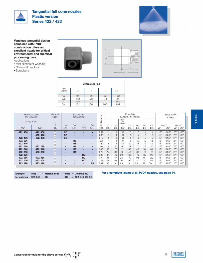
Conversion formula for the above series: V2=V1P2
0.4
P1
( ) 45
Tangential full cone nozzlesPlastic versionSeries 422 / 423
Vaneless tangential design combined with PVDF construction offers an excellent nozzle for critical environmental and chemical processing uses.Applications:• Mist eliminator washing• Chemical reactors• Scrubbers
Example: Type + Material code + Inlet = Ordering no.for ordering 422. 846 + 5E + BE = 422. 846. 5E. BE
L1 L2 H1 H2 Inlet(NPT)
Dimensions [in.]
Product Codesfor Ordering
Flow Rate(Gallons Per Minute)
MaterialCode
PVD
F
litresper
minute
Orifi
ce d
iam
.
Spray angle
Spray Widthat 40psi
Nozzle InletConnection
1/4 1.10 .79 .31 .63 3/8 1.42 .98 .44 .91 1/2 1.95 1.32 .74 1.50 3/4 2.31 1.50 1.00 1.94
1/4 3/8 1/2 3/4 10 20 2 40 60 80 100 H=10" H=20" 90° 120° 5E NPT NPT NPT NPT (in.) psi psi bar psi psi psi psi 90° 120° 90° 120°
For a complete listing of all PVDF nozzles, see page 14.
422. 406 422. 408 BC - - - .059 .1 .2 1.0 .3 .3 .4 .4 15" 34.6" 27" 60" 422. 448 BC - - - .065 .1 .2 1.2 .3 .4 .5 .6 15" 34.6" 27" 60" 422. 486 422. 488 BC - - - .075 .2 .3 1.6 .5 .6 .7 .7 15" 34.6" 27" 60" 422. 606 - BE - - .102 .4 .6 3.1 .9 1.2 1.3 1.5 15" 34.6" 27" 60" 422. 646 - BE - - .118 .6 .8 4.0 1.2 1.5 1.7 1.9 15" 34.6" 27" 60" 422. 726 422. 728 - BE - - .146 .9 1.3 6.3 1.9 2.3 2.7 3.0 15" 34.6" 27" 60" 422. 846 422. 848 - BE - - .205 1.9 2.7 12. 3.8 4.7 5.4 6.1 15" 34.6" 27" 60" 422. 886 422. 888 - BE - - .229 2.4 3.5 16. 4.9 6.0 7.0 7.8 15" 34.6" 27" 60" 422. 926 - - BG - .308 3.1 4.3 20. 6.2 7.6 8.7 9.8 15" 34.6" 27" 60" 422. 966 422. 968 - - BG - .316 3.8 5.4 25. 7.7 9.5 10. 12.2 15" 34.6" 27" 60" 423. 006 423. 008 - - BG - .343 4.8 6.9 31. 9.7 11. 13. 15.4 15" 34.6" 27" 60" 423. 126 423. 128 - - - BK .502 9.7 13. 63. 19. 23. 27. 30. 15" 34.6" 27" 60"
Full
cone
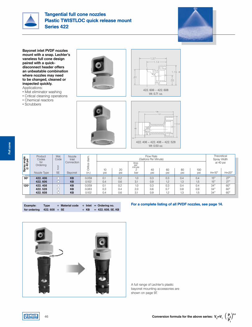
46
Tangential full cone nozzlesPlastic TWISTLOC quick release mountSeries 422
Conversion formula for the above series: V2=V1P2
0.4
P1
( )
Example: Type + Material code + Inlet = Ordering no.for ordering 422. 608 + 5E + KB = 422. 608. 5E. KB
Bayonet inlet PVDF nozzles mount with a snap. Lechler’s vaneless full cone design paired with a quick-disconnect header offers an unbeatable combination where nozzles may need to be changed, cleaned or inspected quickly.Applications:• Mist eliminator washing• Critical cleaning operations• Chemical reactors• Scrubbers
A full range of Lechler’s plastic bayonet mounting accessories are shown on page 97.
ProductCodes
for Ordering
Flow Rate(Gallons Per Minute)
Mat.Code
PVD
F
litresper
minute
Orifi
ce d
iam
.
Spr
ay a
ngle
@ 4
0 ps
i
Nozzle Inlet
Connection
10 20 2 40 60 80 100 Nozzle Type 5E Bayonet (in.) psi psi bar psi psi psi psi H=10" H=20"
Theoretical Spray Width
at 40 psi
422. 606 – 422. 608Wt: 0.71 oz.
422. 406 – 422. 408 – 422. 528Wt: 0.50 oz.
For a complete listing of all PVDF nozzles, see page 14.
90o 422. 406 KB 0.059 0.1 0.2 1.0 0.3 0.3 0.4 0.4 15" 27" 422. 606 KB 0.102 0.4 0.6 3.1 0.9 1.2 1.3 1.5 15" 27" 120o 422. 408 KB 0.059 0.1 0.2 1.0 0.3 0.3 0.4 0.4 34" 60" 422. 528 KB 0.083 0.3 0.4 2.0 0.6 0.7 0.8 0.9 34" 60" 422. 608 KB 0.102 0.4 0.6 3.1 0.9 1.2 1.3 1.5 34" 60"
Full
cone
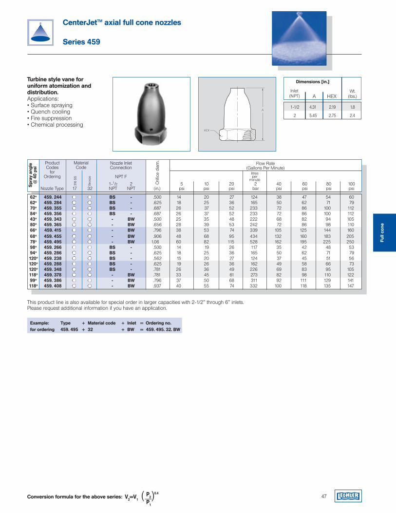
62o 459. 244 BS - .500 14 20 27 124 38 47 54 60 62o 459. 284 BS - .625 18 25 36 165 50 62 71 79 70o 459. 355 BS - .687 26 37 52 233 72 86 100 112 84o 459. 356 BS - .687 26 37 52 233 72 86 100 112 43o 459. 343 - BW .500 25 35 48 222 68 82 94 105 80o 459. 365 - BW .656 28 39 53 242 72 86 98 110 66o 459. 415 - BW .796 38 53 74 339 105 125 144 160 68o 459. 455 - BW .906 48 68 95 434 132 160 183 205 78o 459. 495 - BW 1.06 60 82 115 528 162 195 225 250 98o 459. 266 BS - .500 14 19 26 117 35 42 48 53 94o 459. 286 BS - .625 18 25 36 165 50 62 71 79 120o 459. 238 BS - .562 15 20 27 124 37 45 51 56 120o 459. 288 BS - .625 19 26 36 162 49 58 66 73 120o 459. 348 BS - .781 26 36 49 226 69 83 95 105 118o 459. 378 - BW .781 33 45 61 273 82 98 110 122 99o 459. 386 - BW .796 37 50 68 311 92 111 129 141 118o 459. 408 - BW .937 40 55 74 332 100 118 135 147
ProductCodes
for Ordering
Flow Rate(Gallons Per Minute)
MaterialCode
316
SS
Bro
nze
17 32
litresper
minute
Orifi
ce d
iam
.
Spr
ay a
ngle
@ 4
0 ps
i
Nozzle Inlet Connection
NPT F
1-1/2 2 5 10 20 2 40 60 80 100 Nozzle Type NPT NPT (in.) psi psi psi bar psi psi psi psi
47
CenterJet™ axial full cone nozzles
Series 459
Turbine style vane for uniform atomization and distribution.Applications:• Surface spraying• Quench cooling• Fire suppression• Chemical processing
This product line is also available for special order in larger capacities with 2-1/2" through 6" inlets. Please request additional information if you have an application.
Example: Type + Material code + Inlet = Ordering no.for ordering 459. 495 + 32 + BW = 459. 495. 32. BW
Dimensions [in.]
A HEX Inlet(NPT)
Wt.(lbs.)
1-1/2 4.31 2.19 1.8
2 5.45 2.75 2.4
Conversion formula for the above series: V2=V1P2
0.4
P1
( )
Full
cone
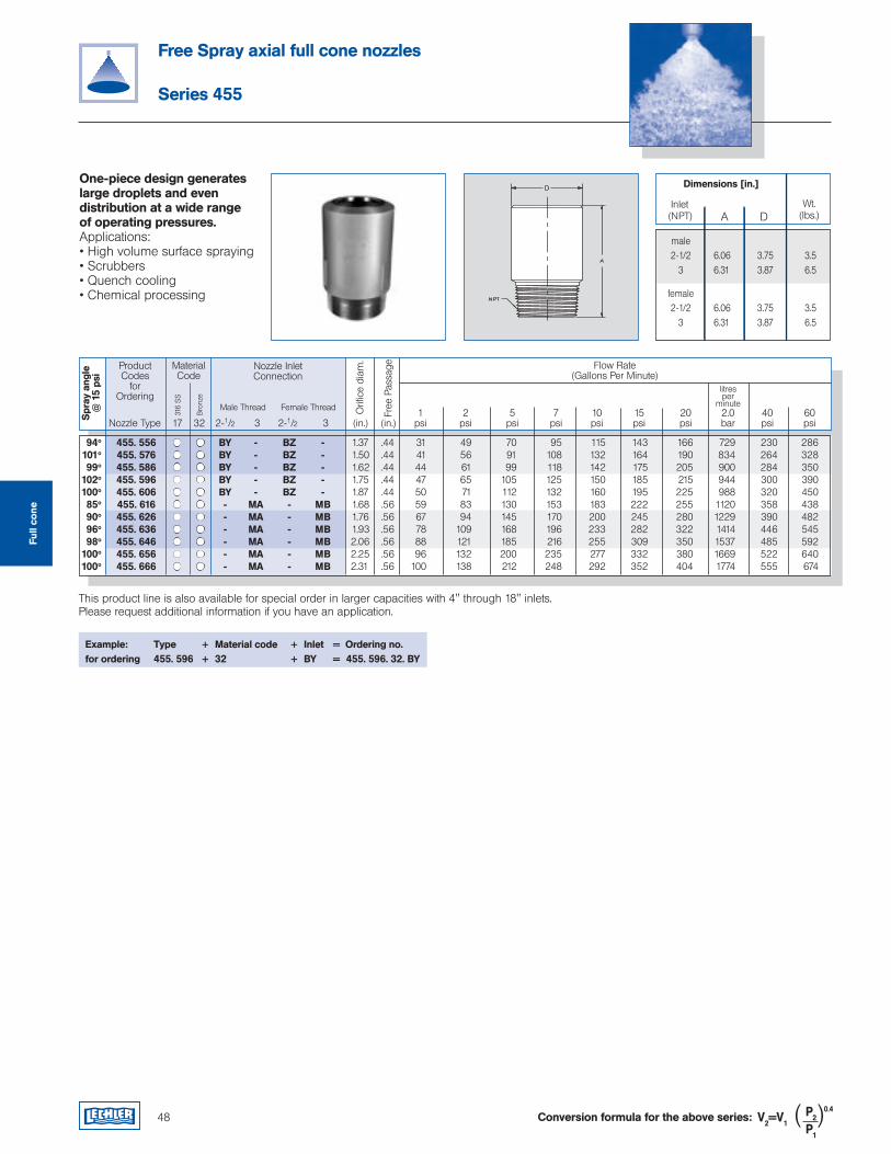
94o 455. 556 BY - BZ - 1.37 .44 31 49 70 95 115 143 166 729 230 286 101o 455. 576 BY - BZ - 1.50 .44 41 56 91 108 132 164 190 834 264 328 99o 455. 586 BY - BZ - 1.62 .44 44 61 99 118 142 175 205 900 284 350 102o 455. 596 BY - BZ - 1.75 .44 47 65 105 125 150 185 215 944 300 390 100o 455. 606 BY - BZ - 1.87 .44 50 71 112 132 160 195 225 988 320 450 85o 455. 616 - MA - MB 1.68 .56 59 83 130 153 183 222 255 1120 358 438 90o 455. 626 - MA - MB 1.76 .56 67 94 145 170 200 245 280 1229 390 482 96o 455. 636 - MA - MB 1.93 .56 78 109 168 196 233 282 322 1414 446 545 98o 455. 646 - MA - MB 2.06 .56 88 121 185 216 255 309 350 1537 485 592 100o 455. 656 - MA - MB 2.25 .56 96 132 200 235 277 332 380 1669 522 640 100o 455. 666 - MA - MB 2.31 .56 100 138 212 248 292 352 404 1774 555 674
ProductCodes
for Ordering
Flow Rate(Gallons Per Minute)
MaterialCode
316
SS
Bro
nze
17 32
litresper
minute
Orifi
ce d
iam
.
Spr
ay a
ngle
@ 1
5 ps
i
Nozzle Inlet Connection
Male Thread Female Thread
Free
Pas
sage
1 2 5 7 10 15 20 2.0 40 60 Nozzle Type 2-1/2 3 2-1/2 3 (in.) (in.) psi psi psi psi psi psi psi bar psi psi
48
Free Spray axial full cone nozzles
Series 455
One-piece design generates large droplets and even distribution at a wide range of operating pressures.Applications:• High volume surface spraying• Scrubbers• Quench cooling• Chemical processing
This product line is also available for special order in larger capacities with 4" through 18" inlets. Please request additional information if you have an application.
Example: Type + Material code + Inlet = Ordering no.for ordering 455. 596 + 32 + BY = 455. 596. 32. BY
Dimensions [in.]
A D Inlet(NPT)
Wt.(lbs.)
male 2-1/2 6.06 3.75 3.5 3 6.31 3.87 6.5
female 2-1/2 6.06 3.75 3.5 3 6.31 3.87 6.5
Conversion formula for the above series: V2=V1P2
0.4
P1
( )
Full
cone

Belt cleaningCoatingSteam cleaningDegreasingHigh pressure cleaningGravel washingCoolingSurface treatmentPhosphatingRain curtainsFoam controlFoam sprayingLubricationFilter cleaningSpray cleaningWashing processesand many others...
Flat fan nozzles
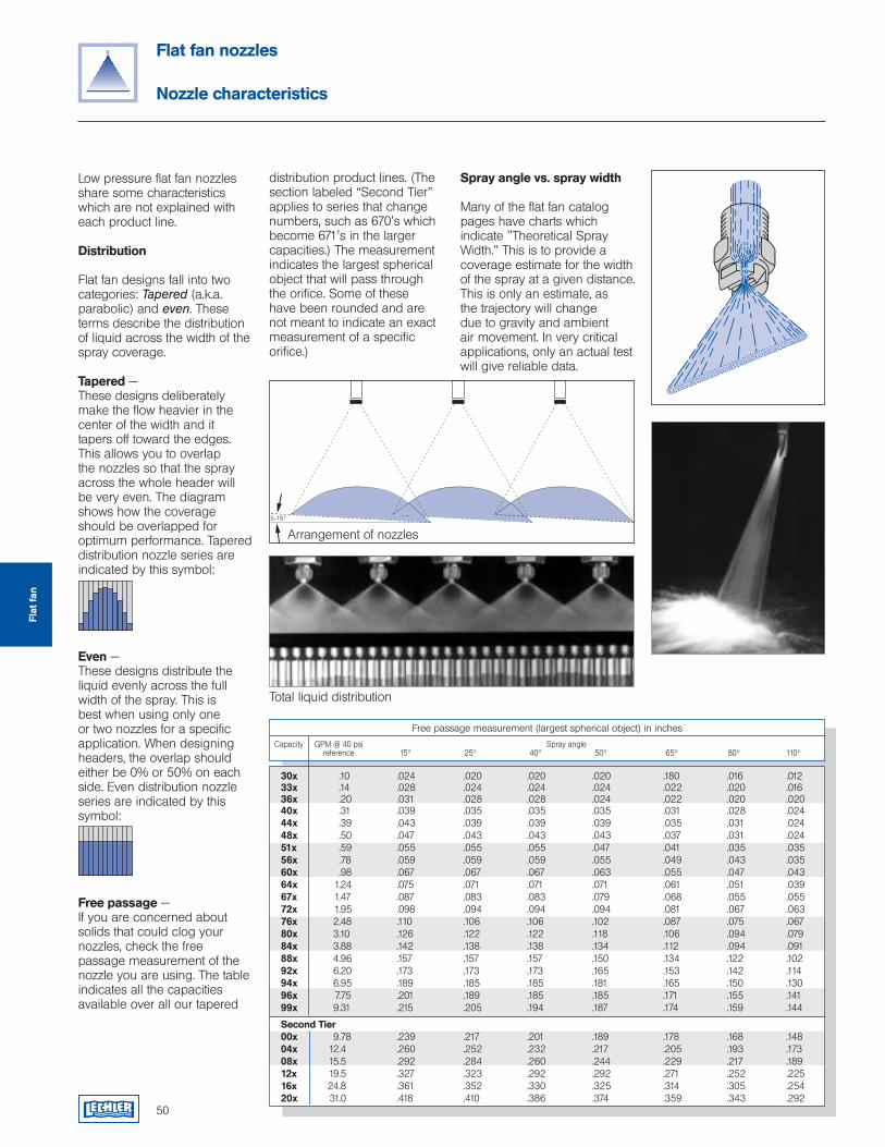
5-15°
Low pressure flat fan nozzles share some characteristics which are not explained with each product line.
Distribution
Flat fan designs fall into two categories: Tapered (a.k.a. parabolic) and even. These terms describe the distribution of liquid across the width of the spray coverage.
Tapered —These designs deliberately make the flow heavier in the center of the width and it tapers off toward the edges. This allows you to overlap the nozzles so that the spray across the whole header will be very even. The diagram shows how the coverage should be overlapped for optimum performance. Tapered distribution nozzle series are indicated by this symbol:
Even —These designs distribute the liquid evenly across the full width of the spray. This is best when using only one or two nozzles for a specific application. When designing headers, the overlap should either be 0% or 50% on each side. Even distribution nozzle series are indicated by this symbol:
Free passage —If you are concerned about solids that could clog your nozzles, check the free passage measurement of the nozzle you are using. The table indicates all the capacities available over all our tapered
Total liquid distribution
Arrangement of nozzles
50
Flat fan nozzles
Nozzle characteristics
distribution product lines. (The section labeled “Second Tier” applies to series that change numbers, such as 670's which become 671's in the larger capacities.) The measurement indicates the largest spherical object that will pass through the orifice. Some of these have been rounded and are not meant to indicate an exact measurement of a specific orifice.)
Spray angle vs. spray width
Many of the flat fan catalog pages have charts which indicate "Theoretical Spray Width.” This is to provide a coverage estimate for the width of the spray at a given distance. This is only an estimate, as the trajectory will change due to gravity and ambient air movement. In very critical applications, only an actual test will give reliable data.
Capacity GPM @ 40 psi Spray angle reference 15° 25° 40° 50° 65° 80° 110°
Free passage measurement (largest spherical object) in inches
30x .10 .024 .020 .020 .020 .180 .016 .012 33x .14 .028 .024 .024 .024 .022 .020 .016 36x .20 .031 .028 .028 .024 .022 .020 .020 40x .31 .039 .035 .035 .035 .031 .028 .024 44x .39 .043 .039 .039 .039 .035 .031 .024 48x .50 .047 .043 .043 .043 .037 .031 .024 51x .59 .055 .055 .055 .047 .041 .035 .035 56x .78 .059 .059 .059 .055 .049 .043 .035 60x .98 .067 .067 .067 .063 .055 .047 .043 64x 1.24 .075 .071 .071 .071 .061 .051 .039 67x 1.47 .087 .083 .083 .079 .068 .055 .055 72x 1.95 .098 .094 .094 .094 .081 .067 .063 76x 2.48 .110 .106 .106 .102 .087 .075 .067 80x 3.10 .126 .122 .122 .118 .106 .094 .079 84x 3.88 .142 .138 .138 .134 .112 .094 .091 88x 4.96 .157 .157 .157 .150 .134 .122 .102 92x 6.20 .173 .173 .173 .165 .153 .142 .114 94x 6.95 .189 .185 .185 .181 .165 .150 .130 96x 7.75 .201 .189 .185 .185 .171 .155 .141 99x 9.31 .215 .205 .194 .187 .174 .159 .144
Second Tier 00x 9.78 .239 .217 .201 .189 .178 .168 .148 04x 12.4 .260 .252 .232 .217 .205 .193 .173 08x 15.5 .292 .284 .260 .244 .229 .217 .189 12x 19.5 .327 .323 .292 .292 .271 .252 .225 16x 24.8 .361 .352 .330 .325 .314 .305 .254 20x 31.0 .418 .410 .386 .374 .359 .343 .292
Flat
fan
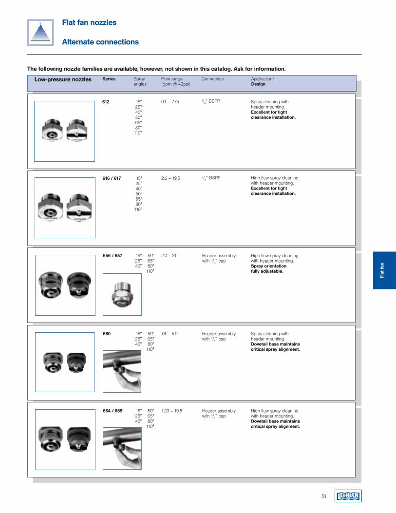
3/4" BSPP
Low-pressure nozzles Series Spray Flow range Connection Application/ angles (gpm @ 40psi) Design
51
Flat fan nozzles
Alternate connections
612 15°25°40°50°65°80°
110°
0.1 – 7.75 1/4" BSPP Spray cleaning with header mounting. Excellent for tight clearance installation.
616 / 617 15°25°40°50°65°80°
110°
2.0 – 19.5 High flow spray cleaning with header mounting. Excellent for tight clearance installation.
656 / 657 15°25°40°
50°65°80°
110°
2.0 – 31 Header assembly with 3/4" cap
High flow spray cleaning with header mounting.Spray orientation fully adjustable.
660 15°25°40°
50°65°80°
110°
.01 – 5.0 Header assembly with 3/8" cap
Spray cleaning with header mounting.Dovetail base maintains critical spray alignment.
664 / 665 15°25°40°
50°65°80°
110°
1.23 – 19.5 Header assembly with 3/4" cap
High flow spray cleaning with header mounting.Dovetail base maintains critical spray alignment.
The following nozzle families are available, however, not shown in this catalog. Ask for information.
Flat
fan
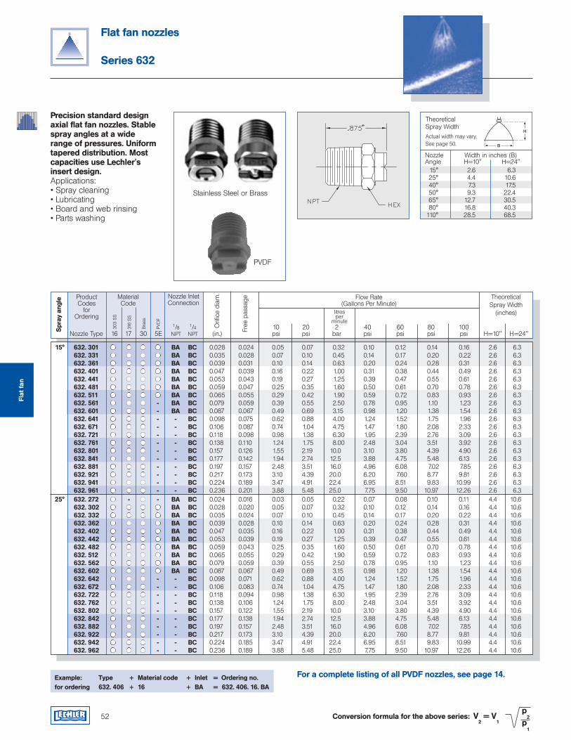
52
Flat fan nozzles
Series 632
Precision standard design axial flat fan nozzles. Stable spray angles at a wide range of pressures. Uniform tapered distribution. Most capacities use Lechler's insert design.Applications:• Spray cleaning• Lubricating• Board and web rinsing• Parts washing
Example: Type + Material code + Inlet = Ordering no.for ordering 632. 406 + 16 + BA = 632. 406. 16. BA
Conversion formula for the above series: V2 = V
1
p2
p1
ProductCodes
for Ordering
Flow Rate(Gallons Per Minute)
TheoreticalSpray Width
(inches)
1/8 1/4 10 20 2 40 60 80 100 Nozzle Type 16 17 30 5E NPT NPT (in.) psi psi bar psi psi psi psi H=10" H=24"
MaterialCode
303
SS
316
SS
litresper
minute
Nozzle Inlet Connection
Orifi
ce d
iam
.
Spr
ay a
ngle
Bra
ss
PVD
F
Free
pas
sage
PVDF
Stainless Steel or Brass
Theoretical Spray WidthActual width may vary.See page 50.
H
B
Nozzle Width in inches (B)Angle H=10" H=24" 15° 2.6 6.3 25° 4.4 10.6 40° 7.3 17.5 50° 9.3 22.4 65° 12.7 30.5 80° 16.8 40.3110° 28.5 68.5
For a complete listing of all PVDF nozzles, see page 14.
Flat
fan
15° 632. 301 BA BC 0.028 0.024 0.05 0.07 0.32 0.10 0.12 0.14 0.16 2.6 6.3 632. 331 BA BC 0.035 0.028 0.07 0.10 0.45 0.14 0.17 0.20 0.22 2.6 6.3 632. 361 BA BC 0.039 0.031 0.10 0.14 0.63 0.20 0.24 0.28 0.31 2.6 6.3 632. 401 BA BC 0.047 0.039 0.16 0.22 1.00 0.31 0.38 0.44 0.49 2.6 6.3 632. 441 BA BC 0.053 0.043 0.19 0.27 1.25 0.39 0.47 0.55 0.61 2.6 6.3 632. 481 BA BC 0.059 0.047 0.25 0.35 1.60 0.50 0.61 0.70 0.78 2.6 6.3 632. 511 BA BC 0.065 0.055 0.29 0.42 1.90 0.59 0.72 0.83 0.93 2.6 6.3 632. 561 - BA BC 0.079 0.059 0.39 0.55 2.50 0.78 0.95 1.10 1.23 2.6 6.3 632. 601 - BA BC 0.087 0.067 0.49 0.69 3.15 0.98 1.20 1.38 1.54 2.6 6.3 632. 641 - - BC 0.098 0.075 0.62 0.88 4.00 1.24 1.52 1.75 1.96 2.6 6.3 632. 671 - - BC 0.106 0.087 0.74 1.04 4.75 1.47 1.80 2.08 2.33 2.6 6.3 632. 721 - - BC 0.118 0.098 0.98 1.38 6.30 1.95 2.39 2.76 3.09 2.6 6.3 632. 761 - - BC 0.138 0.110 1.24 1.75 8.00 2.48 3.04 3.51 3.92 2.6 6.3 632. 801 - - BC 0.157 0.126 1.55 2.19 10.0 3.10 3.80 4.39 4.90 2.6 6.3 632. 841 - - BC 0.177 0.142 1.94 2.74 12.5 3.88 4.75 5.48 6.13 2.6 6.3 632. 881 - - BC 0.197 0.157 2.48 3.51 16.0 4.96 6.08 7.02 7.85 2.6 6.3 632. 921 - - BC 0.217 0.173 3.10 4.39 20.0 6.20 7.60 8.77 9.81 2.6 6.3 632. 941 - - BC 0.224 0.189 3.47 4.91 22.4 6.95 8.51 9.83 10.99 2.6 6.3 632. 961 - - BC 0.236 0.201 3.88 5.48 25.0 7.75 9.50 10.97 12.26 2.6 6.3 25° 632. 272 - - BA BC 0.024 0.016 0.03 0.05 0.22 0.07 0.08 0.10 0.11 4.4 10.6 632. 302 BA BC 0.028 0.020 0.05 0.07 0.32 0.10 0.12 0.14 0.16 4.4 10.6 632. 332 BA BC 0.035 0.024 0.07 0.10 0.45 0.14 0.17 0.20 0.22 4.4 10.6 632. 362 BA BC 0.039 0.028 0.10 0.14 0.63 0.20 0.24 0.28 0.31 4.4 10.6 632. 402 BA BC 0.047 0.035 0.16 0.22 1.00 0.31 0.38 0.44 0.49 4.4 10.6 632. 442 BA BC 0.053 0.039 0.19 0.27 1.25 0.39 0.47 0.55 0.61 4.4 10.6 632. 482 BA BC 0.059 0.043 0.25 0.35 1.60 0.50 0.61 0.70 0.78 4.4 10.6 632. 512 BA BC 0.065 0.055 0.29 0.42 1.90 0.59 0.72 0.83 0.93 4.4 10.6 632. 562 BA BC 0.079 0.059 0.39 0.55 2.50 0.78 0.95 1.10 1.23 4.4 10.6 632. 602 BA BC 0.087 0.067 0.49 0.69 3.15 0.98 1.20 1.38 1.54 4.4 10.6 632. 642 - - BC 0.098 0.071 0.62 0.88 4.00 1.24 1.52 1.75 1.96 4.4 10.6 632. 672 - - BC 0.106 0.083 0.74 1.04 4.75 1.47 1.80 2.08 2.33 4.4 10.6 632. 722 - - BC 0.118 0.094 0.98 1.38 6.30 1.95 2.39 2.76 3.09 4.4 10.6 632. 762 - - BC 0.138 0.106 1.24 1.75 8.00 2.48 3.04 3.51 3.92 4.4 10.6 632. 802 - - BC 0.157 0.122 1.55 2.19 10.0 3.10 3.80 4.39 4.90 4.4 10.6 632. 842 - - BC 0.177 0.138 1.94 2.74 12.5 3.88 4.75 5.48 6.13 4.4 10.6 632. 882 - - BC 0.197 0.157 2.48 3.51 16.0 4.96 6.08 7.02 7.85 4.4 10.6 632. 922 - - BC 0.217 0.173 3.10 4.39 20.0 6.20 7.60 8.77 9.81 4.4 10.6 632. 942 - - BC 0.224 0.185 3.47 4.91 22.4 6.95 8.51 9.83 10.99 4.4 10.6 632. 962 - - BC 0.236 0.189 3.88 5.48 25.0 7.75 9.50 10.97 12.26 4.4 10.6
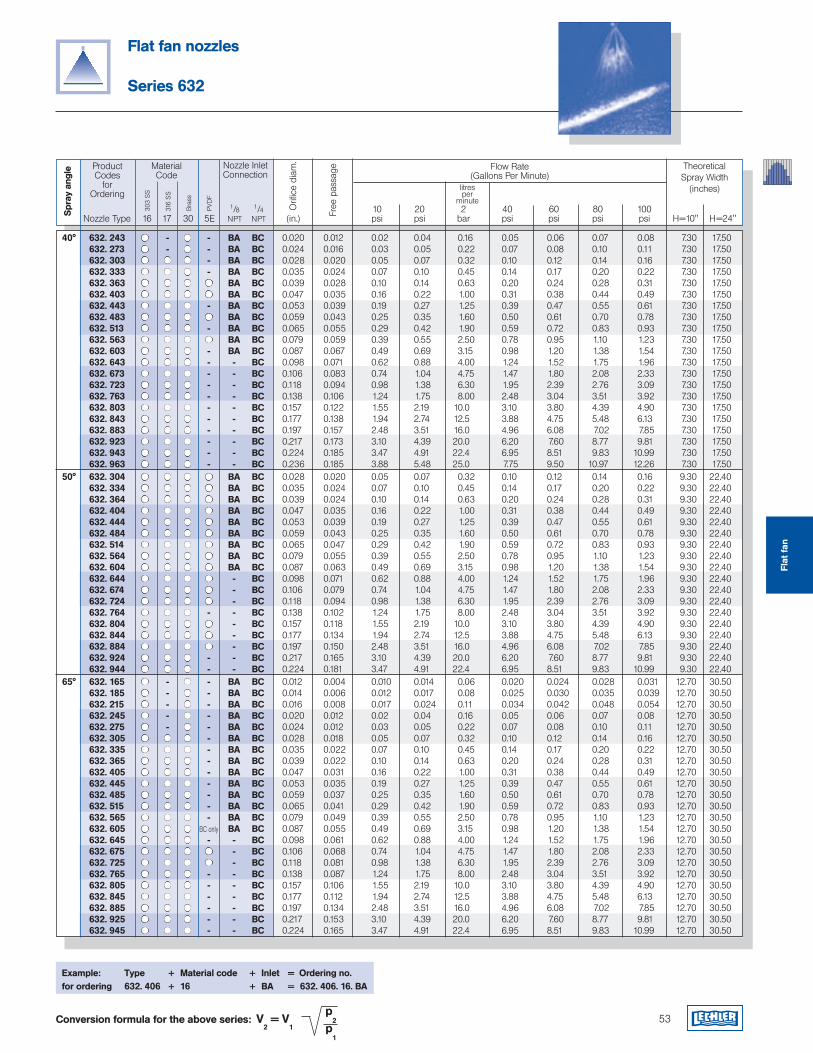
Conversion formula for the above series: V2 = V
1
p2
p1
53
Flat fan nozzles
Series 632
ProductCodes
for Ordering
Flow Rate(Gallons Per Minute)
TheoreticalSpray Width
(inches)
1/8 1/4 10 20 2 40 60 80 100 Nozzle Type 16 17 30 5E NPT NPT (in.) psi psi bar psi psi psi psi H=10" H=24"
MaterialCode
303
SS
316
SS
litresper
minute
Nozzle Inlet Connection
Orifi
ce d
iam
.
Spr
ay a
ngle
Bra
ss
PVD
F
Free
pas
sage
Example: Type + Material code + Inlet = Ordering no.for ordering 632. 406 + 16 + BA = 632. 406. 16. BA
Flat
fan
40° 632. 243 - - BA BC 0.020 0.012 0.02 0.04 0.16 0.05 0.06 0.07 0.08 7.30 17.50 632. 273 - - BA BC 0.024 0.016 0.03 0.05 0.22 0.07 0.08 0.10 0.11 7.30 17.50 632. 303 - BA BC 0.028 0.020 0.05 0.07 0.32 0.10 0.12 0.14 0.16 7.30 17.50 632. 333 - BA BC 0.035 0.024 0.07 0.10 0.45 0.14 0.17 0.20 0.22 7.30 17.50 632. 363 BA BC 0.039 0.028 0.10 0.14 0.63 0.20 0.24 0.28 0.31 7.30 17.50 632. 403 BA BC 0.047 0.035 0.16 0.22 1.00 0.31 0.38 0.44 0.49 7.30 17.50 632. 443 - BA BC 0.053 0.039 0.19 0.27 1.25 0.39 0.47 0.55 0.61 7.30 17.50 632. 483 BA BC 0.059 0.043 0.25 0.35 1.60 0.50 0.61 0.70 0.78 7.30 17.50 632. 513 - BA BC 0.065 0.055 0.29 0.42 1.90 0.59 0.72 0.83 0.93 7.30 17.50 632. 563 BA BC 0.079 0.059 0.39 0.55 2.50 0.78 0.95 1.10 1.23 7.30 17.50 632. 603 - BA BC 0.087 0.067 0.49 0.69 3.15 0.98 1.20 1.38 1.54 7.30 17.50 632. 643 - - BC 0.098 0.071 0.62 0.88 4.00 1.24 1.52 1.75 1.96 7.30 17.50 632. 673 - - BC 0.106 0.083 0.74 1.04 4.75 1.47 1.80 2.08 2.33 7.30 17.50 632. 723 - - BC 0.118 0.094 0.98 1.38 6.30 1.95 2.39 2.76 3.09 7.30 17.50 632. 763 - - BC 0.138 0.106 1.24 1.75 8.00 2.48 3.04 3.51 3.92 7.30 17.50 632. 803 - - BC 0.157 0.122 1.55 2.19 10.0 3.10 3.80 4.39 4.90 7.30 17.50 632. 843 - - BC 0.177 0.138 1.94 2.74 12.5 3.88 4.75 5.48 6.13 7.30 17.50 632. 883 - - BC 0.197 0.157 2.48 3.51 16.0 4.96 6.08 7.02 7.85 7.30 17.50 632. 923 - - BC 0.217 0.173 3.10 4.39 20.0 6.20 7.60 8.77 9.81 7.30 17.50 632. 943 - - BC 0.224 0.185 3.47 4.91 22.4 6.95 8.51 9.83 10.99 7.30 17.50 632. 963 - - BC 0.236 0.185 3.88 5.48 25.0 7.75 9.50 10.97 12.26 7.30 17.50 50° 632. 304 BA BC 0.028 0.020 0.05 0.07 0.32 0.10 0.12 0.14 0.16 9.30 22.40 632. 334 BA BC 0.035 0.024 0.07 0.10 0.45 0.14 0.17 0.20 0.22 9.30 22.40 632. 364 BA BC 0.039 0.024 0.10 0.14 0.63 0.20 0.24 0.28 0.31 9.30 22.40 632. 404 BA BC 0.047 0.035 0.16 0.22 1.00 0.31 0.38 0.44 0.49 9.30 22.40 632. 444 BA BC 0.053 0.039 0.19 0.27 1.25 0.39 0.47 0.55 0.61 9.30 22.40 632. 484 BA BC 0.059 0.043 0.25 0.35 1.60 0.50 0.61 0.70 0.78 9.30 22.40 632. 514 BA BC 0.065 0.047 0.29 0.42 1.90 0.59 0.72 0.83 0.93 9.30 22.40 632. 564 BA BC 0.079 0.055 0.39 0.55 2.50 0.78 0.95 1.10 1.23 9.30 22.40 632. 604 BA BC 0.087 0.063 0.49 0.69 3.15 0.98 1.20 1.38 1.54 9.30 22.40 632. 644 - BC 0.098 0.071 0.62 0.88 4.00 1.24 1.52 1.75 1.96 9.30 22.40 632. 674 - BC 0.106 0.079 0.74 1.04 4.75 1.47 1.80 2.08 2.33 9.30 22.40 632. 724 - BC 0.118 0.094 0.98 1.38 6.30 1.95 2.39 2.76 3.09 9.30 22.40 632. 764 - - BC 0.138 0.102 1.24 1.75 8.00 2.48 3.04 3.51 3.92 9.30 22.40 632. 804 - BC 0.157 0.118 1.55 2.19 10.0 3.10 3.80 4.39 4.90 9.30 22.40 632. 844 - BC 0.177 0.134 1.94 2.74 12.5 3.88 4.75 5.48 6.13 9.30 22.40 632. 884 - BC 0.197 0.150 2.48 3.51 16.0 4.96 6.08 7.02 7.85 9.30 22.40 632. 924 - - BC 0.217 0.165 3.10 4.39 20.0 6.20 7.60 8.77 9.81 9.30 22.40 632. 944 - - BC 0.224 0.181 3.47 4.91 22.4 6.95 8.51 9.83 10.99 9.30 22.40 65° 632. 165 - - BA BC 0.012 0.004 0.010 0.014 0.06 0.020 0.024 0.028 0.031 12.70 30.50 632. 185 - - BA BC 0.014 0.006 0.012 0.017 0.08 0.025 0.030 0.035 0.039 12.70 30.50 632. 215 - - BA BC 0.016 0.008 0.017 0.024 0.11 0.034 0.042 0.048 0.054 12.70 30.50 632. 245 - - BA BC 0.020 0.012 0.02 0.04 0.16 0.05 0.06 0.07 0.08 12.70 30.50 632. 275 - - BA BC 0.024 0.012 0.03 0.05 0.22 0.07 0.08 0.10 0.11 12.70 30.50 632. 305 - BA BC 0.028 0.018 0.05 0.07 0.32 0.10 0.12 0.14 0.16 12.70 30.50 632. 335 - BA BC 0.035 0.022 0.07 0.10 0.45 0.14 0.17 0.20 0.22 12.70 30.50 632. 365 - BA BC 0.039 0.022 0.10 0.14 0.63 0.20 0.24 0.28 0.31 12.70 30.50 632. 405 - BA BC 0.047 0.031 0.16 0.22 1.00 0.31 0.38 0.44 0.49 12.70 30.50 632. 445 - BA BC 0.053 0.035 0.19 0.27 1.25 0.39 0.47 0.55 0.61 12.70 30.50 632. 485 - BA BC 0.059 0.037 0.25 0.35 1.60 0.50 0.61 0.70 0.78 12.70 30.50 632. 515 - BA BC 0.065 0.041 0.29 0.42 1.90 0.59 0.72 0.83 0.93 12.70 30.50 632. 565 - BA BC 0.079 0.049 0.39 0.55 2.50 0.78 0.95 1.10 1.23 12.70 30.50 632. 605 BC only BA BC 0.087 0.055 0.49 0.69 3.15 0.98 1.20 1.38 1.54 12.70 30.50 632. 645 - - BC 0.098 0.061 0.62 0.88 4.00 1.24 1.52 1.75 1.96 12.70 30.50 632. 675 - BC 0.106 0.068 0.74 1.04 4.75 1.47 1.80 2.08 2.33 12.70 30.50 632. 725 - BC 0.118 0.081 0.98 1.38 6.30 1.95 2.39 2.76 3.09 12.70 30.50 632. 765 - - BC 0.138 0.087 1.24 1.75 8.00 2.48 3.04 3.51 3.92 12.70 30.50 632. 805 - - BC 0.157 0.106 1.55 2.19 10.0 3.10 3.80 4.39 4.90 12.70 30.50 632. 845 - - BC 0.177 0.112 1.94 2.74 12.5 3.88 4.75 5.48 6.13 12.70 30.50 632. 885 - - BC 0.197 0.134 2.48 3.51 16.0 4.96 6.08 7.02 7.85 12.70 30.50 632. 925 - - BC 0.217 0.153 3.10 4.39 20.0 6.20 7.60 8.77 9.81 12.70 30.50 632. 945 - - BC 0.224 0.165 3.47 4.91 22.4 6.95 8.51 9.83 10.99 12.70 30.50
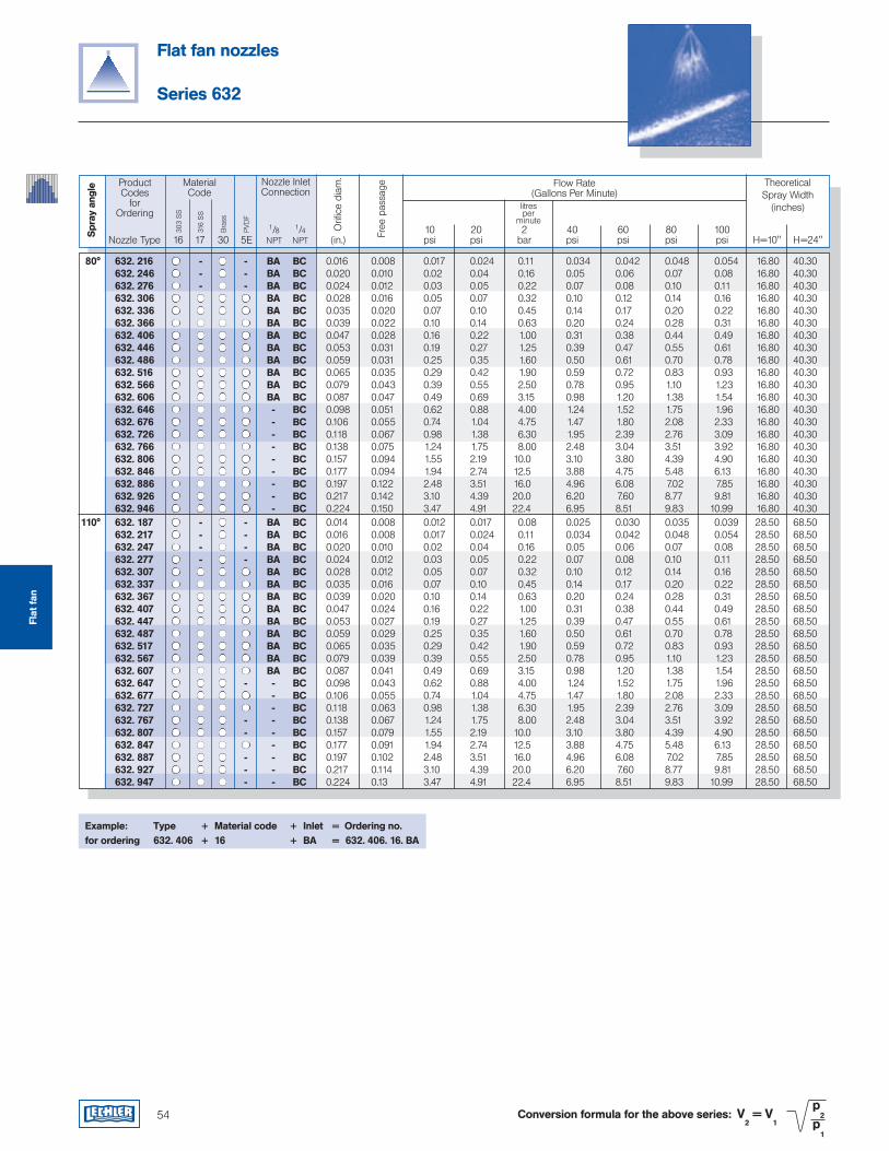
Flat fan nozzles
Series 632
Conversion formula for the above series: V2 = V
1
p2
p1
ProductCodes
for Ordering
Flow Rate(Gallons Per Minute)
TheoreticalSpray Width
(inches)
1/8 1/4 10 20 2 40 60 80 100 Nozzle Type 16 17 30 5E NPT NPT (in.) psi psi bar psi psi psi psi H=10" H=24"
MaterialCode
303
SS
316
SS
litresper
minute
Nozzle Inlet Connection
Orifi
ce d
iam
.
Spr
ay a
ngle
Bra
ss
PVD
F
Example: Type + Material code + Inlet = Ordering no.for ordering 632. 406 + 16 + BA = 632. 406. 16. BA
Free
pas
sage
80° 632. 216 - - BA BC 0.016 0.008 0.017 0.024 0.11 0.034 0.042 0.048 0.054 16.80 40.30 632. 246 - - BA BC 0.020 0.010 0.02 0.04 0.16 0.05 0.06 0.07 0.08 16.80 40.30 632. 276 - - BA BC 0.024 0.012 0.03 0.05 0.22 0.07 0.08 0.10 0.11 16.80 40.30 632. 306 BA BC 0.028 0.016 0.05 0.07 0.32 0.10 0.12 0.14 0.16 16.80 40.30 632. 336 BA BC 0.035 0.020 0.07 0.10 0.45 0.14 0.17 0.20 0.22 16.80 40.30 632. 366 BA BC 0.039 0.022 0.10 0.14 0.63 0.20 0.24 0.28 0.31 16.80 40.30 632. 406 BA BC 0.047 0.028 0.16 0.22 1.00 0.31 0.38 0.44 0.49 16.80 40.30 632. 446 BA BC 0.053 0.031 0.19 0.27 1.25 0.39 0.47 0.55 0.61 16.80 40.30 632. 486 BA BC 0.059 0.031 0.25 0.35 1.60 0.50 0.61 0.70 0.78 16.80 40.30 632. 516 BA BC 0.065 0.035 0.29 0.42 1.90 0.59 0.72 0.83 0.93 16.80 40.30 632. 566 BA BC 0.079 0.043 0.39 0.55 2.50 0.78 0.95 1.10 1.23 16.80 40.30 632. 606 BA BC 0.087 0.047 0.49 0.69 3.15 0.98 1.20 1.38 1.54 16.80 40.30 632. 646 - BC 0.098 0.051 0.62 0.88 4.00 1.24 1.52 1.75 1.96 16.80 40.30 632. 676 - BC 0.106 0.055 0.74 1.04 4.75 1.47 1.80 2.08 2.33 16.80 40.30 632. 726 - BC 0.118 0.067 0.98 1.38 6.30 1.95 2.39 2.76 3.09 16.80 40.30 632. 766 - BC 0.138 0.075 1.24 1.75 8.00 2.48 3.04 3.51 3.92 16.80 40.30 632. 806 - BC 0.157 0.094 1.55 2.19 10.0 3.10 3.80 4.39 4.90 16.80 40.30 632. 846 - BC 0.177 0.094 1.94 2.74 12.5 3.88 4.75 5.48 6.13 16.80 40.30 632. 886 - BC 0.197 0.122 2.48 3.51 16.0 4.96 6.08 7.02 7.85 16.80 40.30 632. 926 - BC 0.217 0.142 3.10 4.39 20.0 6.20 7.60 8.77 9.81 16.80 40.30 632. 946 - BC 0.224 0.150 3.47 4.91 22.4 6.95 8.51 9.83 10.99 16.80 40.30 110° 632. 187 - - BA BC 0.014 0.008 0.012 0.017 0.08 0.025 0.030 0.035 0.039 28.50 68.50 632. 217 - - BA BC 0.016 0.008 0.017 0.024 0.11 0.034 0.042 0.048 0.054 28.50 68.50 632. 247 - - BA BC 0.020 0.010 0.02 0.04 0.16 0.05 0.06 0.07 0.08 28.50 68.50 632. 277 - - BA BC 0.024 0.012 0.03 0.05 0.22 0.07 0.08 0.10 0.11 28.50 68.50 632. 307 BA BC 0.028 0.012 0.05 0.07 0.32 0.10 0.12 0.14 0.16 28.50 68.50 632. 337 BA BC 0.035 0.016 0.07 0.10 0.45 0.14 0.17 0.20 0.22 28.50 68.50 632. 367 BA BC 0.039 0.020 0.10 0.14 0.63 0.20 0.24 0.28 0.31 28.50 68.50 632. 407 BA BC 0.047 0.024 0.16 0.22 1.00 0.31 0.38 0.44 0.49 28.50 68.50 632. 447 BA BC 0.053 0.027 0.19 0.27 1.25 0.39 0.47 0.55 0.61 28.50 68.50 632. 487 BA BC 0.059 0.029 0.25 0.35 1.60 0.50 0.61 0.70 0.78 28.50 68.50 632. 517 BA BC 0.065 0.035 0.29 0.42 1.90 0.59 0.72 0.83 0.93 28.50 68.50 632. 567 BA BC 0.079 0.039 0.39 0.55 2.50 0.78 0.95 1.10 1.23 28.50 68.50 632. 607 BA BC 0.087 0.041 0.49 0.69 3.15 0.98 1.20 1.38 1.54 28.50 68.50 632. 647 - - BC 0.098 0.043 0.62 0.88 4.00 1.24 1.52 1.75 1.96 28.50 68.50 632. 677 - BC 0.106 0.055 0.74 1.04 4.75 1.47 1.80 2.08 2.33 28.50 68.50 632. 727 - BC 0.118 0.063 0.98 1.38 6.30 1.95 2.39 2.76 3.09 28.50 68.50 632. 767 - - BC 0.138 0.067 1.24 1.75 8.00 2.48 3.04 3.51 3.92 28.50 68.50 632. 807 - - BC 0.157 0.079 1.55 2.19 10.0 3.10 3.80 4.39 4.90 28.50 68.50 632. 847 - BC 0.177 0.091 1.94 2.74 12.5 3.88 4.75 5.48 6.13 28.50 68.50 632. 887 - - BC 0.197 0.102 2.48 3.51 16.0 4.96 6.08 7.02 7.85 28.50 68.50 632. 927 - - BC 0.217 0.114 3.10 4.39 20.0 6.20 7.60 8.77 9.81 28.50 68.50 632. 947 - - BC 0.224 0.13 3.47 4.91 22.4 6.95 8.51 9.83 10.99 28.50 68.50
Flat
fan
54
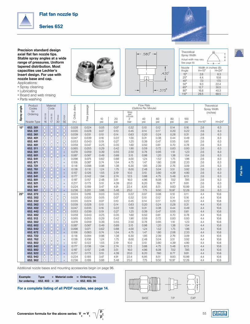
Theoretical Spray WidthActual width may vary.See page 50.
H
B
Nozzle Width in inches (B)Angle H=10" H=24" 15° 2.6 6.3 25° 4.4 10.6 40° 7.3 17.5 50° 9.3 22.4 65° 12.7 30.5 80° 16.8 40.3110° 28.5 68.5
55
Precision standard design axial flat fan nozzle tips. Stable spray angles at a wide range of pressures. Uniform tapered distribution. Most capacities use Lechler's Insert design. For use with nozzle base and cap.Applications:• Spray cleaning• Lubricating• Board and web rinsing• Parts washing
Example: Type + Material code = Ordering no.for ordering 652. 403 + 30 = 652. 403. 30
Flat fan nozzle tip
Series 652
Conversion formula for the above series: V2 = V
1
p2
p1
ProductCodes
for Ordering
Flow Rate(Gallons Per Minute)
TheoreticalSpray Width
(inches)
10 20 2 40 60 80 100 Nozzle Type 16 17 30 5E (in.) psi psi bar psi psi psi psi H=10" H=24"
MaterialCode
litresper
minute
Orifi
ce d
iam
.
Spr
ay a
ngle
Free
pas
sage
Additional nozzle bases and mounting accessories begin on page 96.
For a complete listing of all PVDF nozzles, see page 14.
Flat
fan
15° 652. 301 0.028 0.024 0.05 0.07 0.32 0.10 0.12 0.14 0.16 2.6 6.3 652. 331 0.035 0.028 0.07 0.10 0.45 0.14 0.17 0.20 0.22 2.6 6.3 652. 361 0.039 0.031 0.10 0.14 0.63 0.20 0.24 0.28 0.31 2.6 6.3 652. 401 0.047 0.039 0.16 0.22 1.00 0.31 0.38 0.44 0.49 2.6 6.3 652. 441 0.053 0.043 0.19 0.27 1.25 0.39 0.47 0.55 0.61 2.6 6.3 652. 481 0.059 0.047 0.25 0.35 1.60 0.50 0.61 0.70 0.78 2.6 6.3 652. 511 0.065 0.055 0.29 0.42 1.90 0.59 0.72 0.83 0.93 2.6 6.3 652. 561 - 0.079 0.059 0.39 0.55 2.50 0.78 0.95 1.10 1.23 2.6 6.3 652. 601 - 0.087 0.067 0.49 0.69 3.15 0.98 1.20 1.38 1.54 2.6 6.3 652. 641 - 0.098 0.075 0.62 0.88 4.00 1.24 1.52 1.75 1.96 2.6 6.3 652. 671 - 0.106 0.087 0.74 1.04 4.75 1.47 1.80 2.08 2.33 2.6 6.3 652. 721 - 0.118 0.098 0.98 1.38 6.30 1.95 2.39 2.76 3.09 2.6 6.3 652. 761 - 0.138 0.110 1.24 1.75 8.00 2.48 3.04 3.51 3.92 2.6 6.3 652. 801 - 0.157 0.126 1.55 2.19 10.0 3.10 3.80 4.39 4.90 2.6 6.3 652. 841 - 0.177 0.142 1.94 2.74 12.5 3.88 4.75 5.48 6.13 2.6 6.3 652. 881 - 0.197 0.157 2.48 3.51 16.0 4.96 6.08 7.02 7.85 2.6 6.3 652. 921 - 0.217 0.173 3.10 4.39 20.0 6.20 7.60 8.77 9.81 2.6 6.3 652. 941 - 0.224 0.189 3.47 4.91 22.4 6.95 8.51 9.83 10.99 2.6 6.3 652. 961 - 0.236 0.201 3.88 5.48 25.0 7.75 9.50 10.97 12.26 2.6 6.3 25° 652. 272 - - 0.024 0.016 0.03 0.05 0.22 0.07 0.08 0.10 0.11 4.4 10.6 652. 302 0.028 0.020 0.05 0.07 0.32 0.10 0.12 0.14 0.16 4.4 10.6 652. 332 0.035 0.024 0.07 0.10 0.45 0.14 0.17 0.20 0.22 4.4 10.6 652. 362 0.039 0.028 0.10 0.14 0.63 0.20 0.24 0.28 0.31 4.4 10.6 652. 402 0.047 0.035 0.16 0.22 1.00 0.31 0.38 0.44 0.49 4.4 10.6 652. 442 0.053 0.039 0.19 0.27 1.25 0.39 0.47 0.55 0.61 4.4 10.6 652. 482 0.059 0.043 0.25 0.35 1.60 0.50 0.61 0.70 0.78 4.4 10.6 652. 512 0.065 0.055 0.29 0.42 1.90 0.59 0.72 0.83 0.93 4.4 10.6 652. 562 0.079 0.059 0.39 0.55 2.50 0.78 0.95 1.10 1.23 4.4 10.6 652. 602 0.087 0.067 0.49 0.69 3.15 0.98 1.20 1.38 1.54 4.4 10.6 652. 642 - 0.098 0.071 0.62 0.88 4.00 1.24 1.52 1.75 1.96 4.4 10.6 652. 672 - 0.106 0.083 0.74 1.04 4.75 1.47 1.80 2.08 2.33 4.4 10.6 652. 722 - 0.118 0.094 0.98 1.38 6.30 1.95 2.39 2.76 3.09 4.4 10.6 652. 762 - 0.138 0.106 1.24 1.75 8.00 2.48 3.04 3.51 3.92 4.4 10.6 652. 802 - 0.157 0.122 1.55 2.19 10.0 3.10 3.80 4.39 4.90 4.4 10.6 652. 842 - 0.177 0.138 1.94 2.74 12.5 3.88 4.75 5.48 6.13 4.4 10.6 652. 882 - 0.197 0.157 2.48 3.51 16.0 4.96 6.08 7.02 7.85 4.4 10.6 652. 922 - 0.217 0.173 3.10 4.39 20.0 6.20 7.60 8.77 9.81 4.4 10.6 652. 942 - 0.224 0.185 3.47 4.91 22.4 6.95 8.51 9.83 10.99 4.4 10.6 652. 962 - 0.236 0.189 3.88 5.48 25.0 7.75 9.50 10.97 12.26 4.4 10.6
303
SS
316
SS
Bra
ss
PVD
F
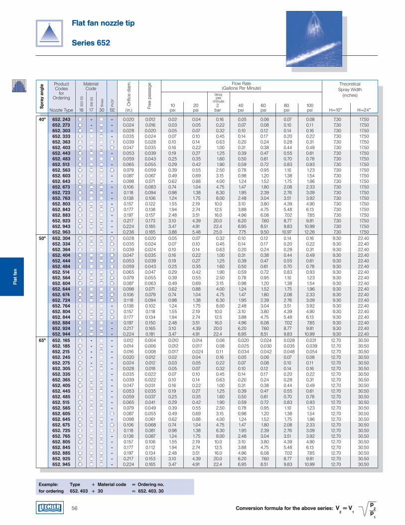
56
Flat fan nozzle tip
Series 652
Conversion formula for the above series: V2 = V
1
p2
p1
Example: Type + Material code = Ordering no.for ordering 652. 403 + 30 = 652. 403. 30
ProductCodes
for Ordering
Flow Rate(Gallons Per Minute)
TheoreticalSpray Width
(inches)
10 20 2 40 60 80 100 Nozzle Type 16 17 30 5E (in.) psi psi bar psi psi psi psi H=10" H=24"
MaterialCode
litresper
minute
Orifi
ce d
iam
.
Spr
ay a
ngle
Free
pas
sage
Flat
fan
40° 652. 243 - - 0.020 0.012 0.02 0.04 0.16 0.05 0.06 0.07 0.08 7.30 17.50 652. 273 - - 0.024 0.016 0.03 0.05 0.22 0.07 0.08 0.10 0.11 7.30 17.50 652. 303 - 0.028 0.020 0.05 0.07 0.32 0.10 0.12 0.14 0.16 7.30 17.50 652. 333 - 0.035 0.024 0.07 0.10 0.45 0.14 0.17 0.20 0.22 7.30 17.50 652. 363 0.039 0.028 0.10 0.14 0.63 0.20 0.24 0.28 0.31 7.30 17.50 652. 403 0.047 0.035 0.16 0.22 1.00 0.31 0.38 0.44 0.49 7.30 17.50 652. 443 - 0.053 0.039 0.19 0.27 1.25 0.39 0.47 0.55 0.61 7.30 17.50 652. 483 0.059 0.043 0.25 0.35 1.60 0.50 0.61 0.70 0.78 7.30 17.50 652. 513 - 0.065 0.055 0.29 0.42 1.90 0.59 0.72 0.83 0.93 7.30 17.50 652. 563 0.079 0.059 0.39 0.55 2.50 0.78 0.95 1.10 1.23 7.30 17.50 652. 603 - 0.087 0.067 0.49 0.69 3.15 0.98 1.20 1.38 1.54 7.30 17.50 652. 643 - 0.098 0.071 0.62 0.88 4.00 1.24 1.52 1.75 1.96 7.30 17.50 652. 673 - 0.106 0.083 0.74 1.04 4.75 1.47 1.80 2.08 2.33 7.30 17.50 652. 723 - 0.118 0.094 0.98 1.38 6.30 1.95 2.39 2.76 3.09 7.30 17.50 652. 763 - 0.138 0.106 1.24 1.75 8.00 2.48 3.04 3.51 3.92 7.30 17.50 652. 803 - 0.157 0.122 1.55 2.19 10.0 3.10 3.80 4.39 4.90 7.30 17.50 652. 843 0.177 0.138 1.94 2.74 12.5 3.88 4.75 5.48 6.13 7.30 17.50 652. 883 - 0.197 0.157 2.48 3.51 16.0 4.96 6.08 7.02 7.85 7.30 17.50 652. 923 - 0.217 0.173 3.10 4.39 20.0 6.20 7.60 8.77 9.81 7.30 17.50 652. 943 - 0.224 0.185 3.47 4.91 22.4 6.95 8.51 9.83 10.99 7.30 17.50 652. 963 - 0.236 0.185 3.88 5.48 25.0 7.75 9.50 10.97 12.26 7.30 17.50 50° 652. 304 0.028 0.020 0.05 0.07 0.32 0.10 0.12 0.14 0.16 9.30 22.40 652. 334 0.035 0.024 0.07 0.10 0.45 0.14 0.17 0.20 0.22 9.30 22.40 652. 364 0.039 0.024 0.10 0.14 0.63 0.20 0.24 0.28 0.31 9.30 22.40 652. 404 0.047 0.035 0.16 0.22 1.00 0.31 0.38 0.44 0.49 9.30 22.40 652. 444 0.053 0.039 0.19 0.27 1.25 0.39 0.47 0.55 0.61 9.30 22.40 652. 484 0.059 0.043 0.25 0.35 1.60 0.50 0.61 0.70 0.78 9.30 22.40 652. 514 0.065 0.047 0.29 0.42 1.90 0.59 0.72 0.83 0.93 9.30 22.40 652. 564 0.079 0.055 0.39 0.55 2.50 0.78 0.95 1.10 1.23 9.30 22.40 652. 604 0.087 0.063 0.49 0.69 3.15 0.98 1.20 1.38 1.54 9.30 22.40 652. 644 0.098 0.071 0.62 0.88 4.00 1.24 1.52 1.75 1.96 9.30 22.40 652. 674 0.106 0.079 0.74 1.04 4.75 1.47 1.80 2.08 2.33 9.30 22.40 652. 724 0.118 0.094 0.98 1.38 6.30 1.95 2.39 2.76 3.09 9.30 22.40 652. 764 - 0.138 0.102 1.24 1.75 8.00 2.48 3.04 3.51 3.92 9.30 22.40 652. 804 0.157 0.118 1.55 2.19 10.0 3.10 3.80 4.39 4.90 9.30 22.40 652. 844 0.177 0.134 1.94 2.74 12.5 3.88 4.75 5.48 6.13 9.30 22.40 652. 884 - 0.197 0.150 2.48 3.51 16.0 4.96 6.08 7.02 7.85 9.30 22.40 652. 924 - 0.217 0.165 3.10 4.39 20.0 6.20 7.60 8.77 9.81 9.30 22.40 652. 944 - 0.224 0.181 3.47 4.91 22.4 6.95 8.51 9.83 10.99 9.30 22.40 65° 652. 165 - - 0.012 0.004 0.010 0.014 0.06 0.020 0.024 0.028 0.031 12.70 30.50 652. 185 - - 0.014 0.006 0.012 0.017 0.08 0.025 0.030 0.035 0.039 12.70 30.50 652. 215 - - 0.016 0.008 0.017 0.024 0.11 0.034 0.042 0.048 0.054 12.70 30.50 652. 245 - - 0.020 0.012 0.02 0.04 0.16 0.05 0.06 0.07 0.08 12.70 30.50 652. 275 - - 0.024 0.012 0.03 0.05 0.22 0.07 0.08 0.10 0.11 12.70 30.50 652. 305 - 0.028 0.018 0.05 0.07 0.32 0.10 0.12 0.14 0.16 12.70 30.50 652. 335 - 0.035 0.022 0.07 0.10 0.45 0.14 0.17 0.20 0.22 12.70 30.50 652. 365 - 0.039 0.022 0.10 0.14 0.63 0.20 0.24 0.28 0.31 12.70 30.50 652. 405 - 0.047 0.031 0.16 0.22 1.00 0.31 0.38 0.44 0.49 12.70 30.50 652. 445 - 0.053 0.035 0.19 0.27 1.25 0.39 0.47 0.55 0.61 12.70 30.50 652. 485 - 0.059 0.037 0.25 0.35 1.60 0.50 0.61 0.70 0.78 12.70 30.50 652. 515 - 0.065 0.041 0.29 0.42 1.90 0.59 0.72 0.83 0.93 12.70 30.50 652. 565 - 0.079 0.049 0.39 0.55 2.50 0.78 0.95 1.10 1.23 12.70 30.50 652. 605 0.087 0.055 0.49 0.69 3.15 0.98 1.20 1.38 1.54 12.70 30.50 652. 645 - 0.098 0.061 0.62 0.88 4.00 1.24 1.52 1.75 1.96 12.70 30.50 652. 675 0.106 0.068 0.74 1.04 4.75 1.47 1.80 2.08 2.33 12.70 30.50 652. 725 0.118 0.081 0.98 1.38 6.30 1.95 2.39 2.76 3.09 12.70 30.50 652. 765 - 0.138 0.087 1.24 1.75 8.00 2.48 3.04 3.51 3.92 12.70 30.50 652. 805 - 0.157 0.106 1.55 2.19 10.0 3.10 3.80 4.39 4.90 12.70 30.50 652. 845 - 0.177 0.112 1.94 2.74 12.5 3.88 4.75 5.48 6.13 12.70 30.50 652. 885 - 0.197 0.134 2.48 3.51 16.0 4.96 6.08 7.02 7.85 12.70 30.50 652. 925 - 0.217 0.153 3.10 4.39 20.0 6.20 7.60 8.77 9.81 12.70 30.50 652. 945 - 0.224 0.165 3.47 4.91 22.4 6.95 8.51 9.83 10.99 12.70 30.50
303
SS
316
SS
Bra
ss
PVD
F
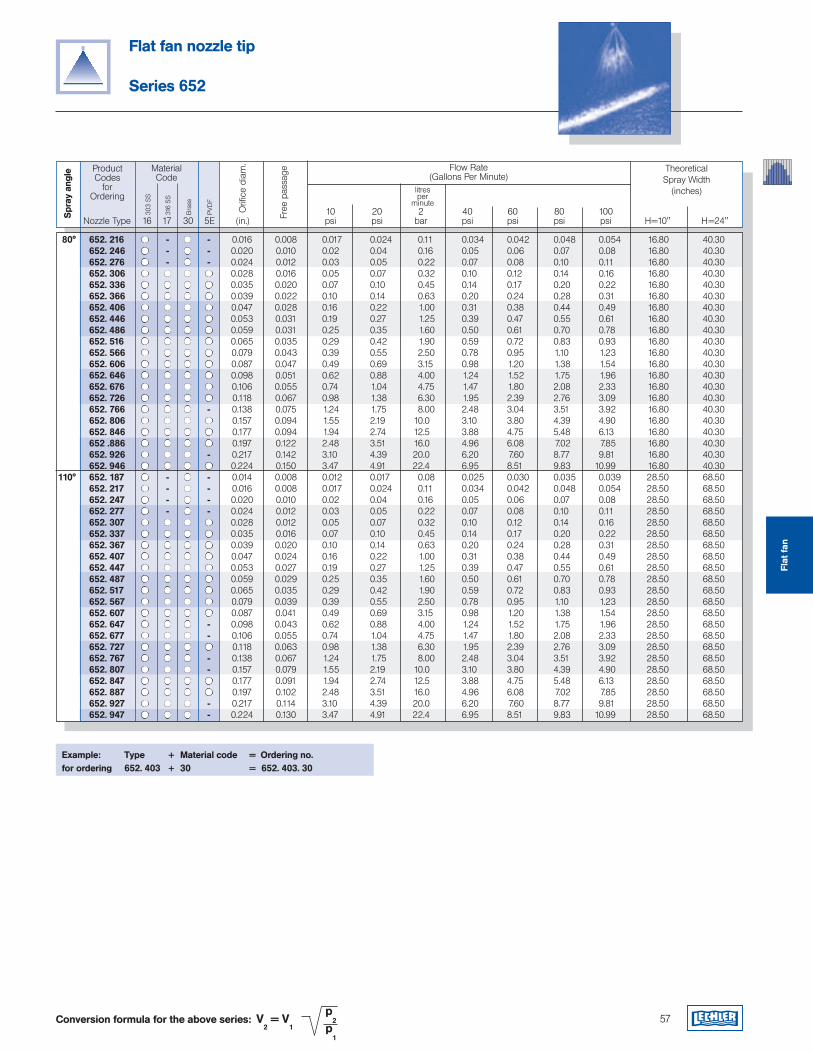
57
Flat fan nozzle tip
Series 652
Conversion formula for the above series: V2 = V
1
p2
p1
ProductCodes
for Ordering
Flow Rate(Gallons Per Minute)
TheoreticalSpray Width
(inches)
10 20 2 40 60 80 100 Nozzle Type 16 17 30 5E (in.) psi psi bar psi psi psi psi H=10" H=24"
MaterialCode
litresper
minute
Orifi
ce d
iam
.
Spr
ay a
ngle
Free
pas
sage
Example: Type + Material code = Ordering no.for ordering 652. 403 + 30 = 652. 403. 30
Flat
fan
80° 652. 216 - - 0.016 0.008 0.017 0.024 0.11 0.034 0.042 0.048 0.054 16.80 40.30 652. 246 - - 0.020 0.010 0.02 0.04 0.16 0.05 0.06 0.07 0.08 16.80 40.30 652. 276 - - 0.024 0.012 0.03 0.05 0.22 0.07 0.08 0.10 0.11 16.80 40.30 652. 306 0.028 0.016 0.05 0.07 0.32 0.10 0.12 0.14 0.16 16.80 40.30 652. 336 0.035 0.020 0.07 0.10 0.45 0.14 0.17 0.20 0.22 16.80 40.30 652. 366 0.039 0.022 0.10 0.14 0.63 0.20 0.24 0.28 0.31 16.80 40.30 652. 406 0.047 0.028 0.16 0.22 1.00 0.31 0.38 0.44 0.49 16.80 40.30 652. 446 0.053 0.031 0.19 0.27 1.25 0.39 0.47 0.55 0.61 16.80 40.30 652. 486 0.059 0.031 0.25 0.35 1.60 0.50 0.61 0.70 0.78 16.80 40.30 652. 516 0.065 0.035 0.29 0.42 1.90 0.59 0.72 0.83 0.93 16.80 40.30 652. 566 0.079 0.043 0.39 0.55 2.50 0.78 0.95 1.10 1.23 16.80 40.30 652. 606 0.087 0.047 0.49 0.69 3.15 0.98 1.20 1.38 1.54 16.80 40.30 652. 646 0.098 0.051 0.62 0.88 4.00 1.24 1.52 1.75 1.96 16.80 40.30 652. 676 0.106 0.055 0.74 1.04 4.75 1.47 1.80 2.08 2.33 16.80 40.30 652. 726 0.118 0.067 0.98 1.38 6.30 1.95 2.39 2.76 3.09 16.80 40.30 652. 766 - 0.138 0.075 1.24 1.75 8.00 2.48 3.04 3.51 3.92 16.80 40.30 652. 806 0.157 0.094 1.55 2.19 10.0 3.10 3.80 4.39 4.90 16.80 40.30 652. 846 0.177 0.094 1.94 2.74 12.5 3.88 4.75 5.48 6.13 16.80 40.30 652 .886 0.197 0.122 2.48 3.51 16.0 4.96 6.08 7.02 7.85 16.80 40.30 652. 926 - 0.217 0.142 3.10 4.39 20.0 6.20 7.60 8.77 9.81 16.80 40.30 652. 946 0.224 0.150 3.47 4.91 22.4 6.95 8.51 9.83 10.99 16.80 40.30 110° 652. 187 - - 0.014 0.008 0.012 0.017 0.08 0.025 0.030 0.035 0.039 28.50 68.50 652. 217 - - 0.016 0.008 0.017 0.024 0.11 0.034 0.042 0.048 0.054 28.50 68.50 652. 247 - - 0.020 0.010 0.02 0.04 0.16 0.05 0.06 0.07 0.08 28.50 68.50 652. 277 - - 0.024 0.012 0.03 0.05 0.22 0.07 0.08 0.10 0.11 28.50 68.50 652. 307 0.028 0.012 0.05 0.07 0.32 0.10 0.12 0.14 0.16 28.50 68.50 652. 337 0.035 0.016 0.07 0.10 0.45 0.14 0.17 0.20 0.22 28.50 68.50 652. 367 0.039 0.020 0.10 0.14 0.63 0.20 0.24 0.28 0.31 28.50 68.50 652. 407 0.047 0.024 0.16 0.22 1.00 0.31 0.38 0.44 0.49 28.50 68.50 652. 447 0.053 0.027 0.19 0.27 1.25 0.39 0.47 0.55 0.61 28.50 68.50 652. 487 0.059 0.029 0.25 0.35 1.60 0.50 0.61 0.70 0.78 28.50 68.50 652. 517 0.065 0.035 0.29 0.42 1.90 0.59 0.72 0.83 0.93 28.50 68.50 652. 567 0.079 0.039 0.39 0.55 2.50 0.78 0.95 1.10 1.23 28.50 68.50 652. 607 0.087 0.041 0.49 0.69 3.15 0.98 1.20 1.38 1.54 28.50 68.50 652. 647 - 0.098 0.043 0.62 0.88 4.00 1.24 1.52 1.75 1.96 28.50 68.50 652. 677 - 0.106 0.055 0.74 1.04 4.75 1.47 1.80 2.08 2.33 28.50 68.50 652. 727 0.118 0.063 0.98 1.38 6.30 1.95 2.39 2.76 3.09 28.50 68.50 652. 767 - 0.138 0.067 1.24 1.75 8.00 2.48 3.04 3.51 3.92 28.50 68.50 652. 807 - 0.157 0.079 1.55 2.19 10.0 3.10 3.80 4.39 4.90 28.50 68.50 652. 847 0.177 0.091 1.94 2.74 12.5 3.88 4.75 5.48 6.13 28.50 68.50 652. 887 0.197 0.102 2.48 3.51 16.0 4.96 6.08 7.02 7.85 28.50 68.50 652. 927 - 0.217 0.114 3.10 4.39 20.0 6.20 7.60 8.77 9.81 28.50 68.50 652. 947 - 0.224 0.130 3.47 4.91 22.4 6.95 8.51 9.83 10.99 28.50 68.50
303
SS
316
SS
Bra
ss
PVD
F
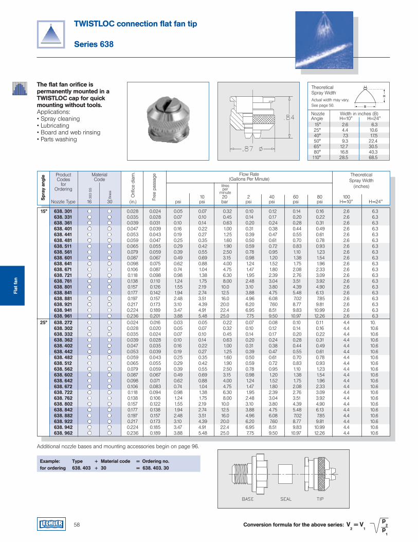
58
Theoretical Spray WidthActual width may vary.See page 50.
H
B
Nozzle Width in inches (B)Angle H=10" H=24" 15° 2.6 6.3 25° 4.4 10.6 40° 7.3 17.5 50° 9.3 22.4 65° 12.7 30.5 80° 16.8 40.3110° 28.5 68.5
TWISTLOC connection flat fan tip
Series 638
Conversion formula for the above series: V2 = V
1
p2
p1
The flat fan orifice is permanently mounted in a TWISTLOC cap for quick mounting without tools.Applications:• Spray cleaning• Lubricating• Board and web rinsing• Parts washing
Example: Type + Material code = Ordering no.for ordering 638. 403 + 30 = 638. 403. 30
ProductCodes
for Ordering
Flow Rate(Gallons Per Minute)
TheoreticalSpray Width
(inches)
10 20 2 40 60 80 100 Nozzle Type 16 30 (in.) psi psi bar psi psi psi psi H=10" H=24"
MaterialCode
303
SS
litresper
minute
Orifi
ce d
iam
.
Spr
ay a
ngle
Bra
ss
Free
pas
sage
Additional nozzle bases and mounting accessories begin on page 96.
Flat
fan
15° 638. 301 0.028 0.024 0.05 0.07 0.32 0.10 0.12 0.14 0.16 2.6 6.3 638. 331 0.035 0.028 0.07 0.10 0.45 0.14 0.17 0.20 0.22 2.6 6.3 638. 361 0.039 0.031 0.10 0.14 0.63 0.20 0.24 0.28 0.31 2.6 6.3 638. 401 0.047 0.039 0.16 0.22 1.00 0.31 0.38 0.44 0.49 2.6 6.3 638. 441 0.053 0.043 0.19 0.27 1.25 0.39 0.47 0.55 0.61 2.6 6.3 638. 481 0.059 0.047 0.25 0.35 1.60 0.50 0.61 0.70 0.78 2.6 6.3 638. 511 0.065 0.055 0.29 0.42 1.90 0.59 0.72 0.83 0.93 2.6 6.3 638. 561 0.079 0.059 0.39 0.55 2.50 0.78 0.95 1.10 1.23 2.6 6.3 638. 601 0.087 0.067 0.49 0.69 3.15 0.98 1.20 1.38 1.54 2.6 6.3 638. 641 0.098 0.075 0.62 0.88 4.00 1.24 1.52 1.75 1.96 2.6 6.3 638. 671 0.106 0.087 0.74 1.04 4.75 1.47 1.80 2.08 2.33 2.6 6.3 638. 721 0.118 0.098 0.98 1.38 6.30 1.95 2.39 2.76 3.09 2.6 6.3 638. 761 0.138 0.110 1.24 1.75 8.00 2.48 3.04 3.51 3.92 2.6 6.3 638. 801 0.157 0.126 1.55 2.19 10.0 3.10 3.80 4.39 4.90 2.6 6.3 638. 841 0.177 0.142 1.94 2.74 12.5 3.88 4.75 5.48 6.13 2.6 6.3 638. 881 0.197 0.157 2.48 3.51 16.0 4.96 6.08 7.02 7.85 2.6 6.3 638. 921 0.217 0.173 3.10 4.39 20.0 6.20 7.60 8.77 9.81 2.6 6.3 638. 941 0.224 0.189 3.47 4.91 22.4 6.95 8.51 9.83 10.99 2.6 6.3 638. 961 0.236 0.201 3.88 5.48 25.0 7.75 9.50 10.97 12.26 2.6 6.3 25° 638. 272 0.024 0.016 0.03 0.05 0.22 0.07 0.08 0.10 0.11 4.4 10. 638. 302 0.028 0.020 0.05 0.07 0.32 0.10 0.12 0.14 0.16 4.4 10.6 638. 332 0.035 0.024 0.07 0.10 0.45 0.14 0.17 0.20 0.22 4.4 10.6 638. 362 0.039 0.028 0.10 0.14 0.63 0.20 0.24 0.28 0.31 4.4 10.6 638. 402 0.047 0.035 0.16 0.22 1.00 0.31 0.38 0.44 0.49 4.4 10.6 638. 442 0.053 0.039 0.19 0.27 1.25 0.39 0.47 0.55 0.61 4.4 10.6 638. 482 0.059 0.043 0.25 0.35 1.60 0.50 0.61 0.70 0.78 4.4 10.6 638. 512 0.065 0.055 0.29 0.42 1.90 0.59 0.72 0.83 0.93 4.4 10.6 638. 562 0.079 0.059 0.39 0.55 2.50 0.78 0.95 1.10 1.23 4.4 10.6 638. 602 0.087 0.067 0.49 0.69 3.15 0.98 1.20 1.38 1.54 4.4 10.6 638. 642 0.098 0.071 0.62 0.88 4.00 1.24 1.52 1.75 1.96 4.4 10.6 638. 672 0.106 0.083 0.74 1.04 4.75 1.47 1.80 2.08 2.33 4.4 10.6 638. 722 0.118 0.094 0.98 1.38 6.30 1.95 2.39 2.76 3.09 4.4 10.6 638. 762 0.138 0.106 1.24 1.75 8.00 2.48 3.04 3.51 3.92 4.4 10.6 638. 802 0.157 0.122 1.55 2.19 10.0 3.10 3.80 4.39 4.90 4.4 10.6 638. 842 0.177 0.138 1.94 2.74 12.5 3.88 4.75 5.48 6.13 4.4 10.6 638. 882 0.197 0.157 2.48 3.51 16.0 4.96 6.08 7.02 7.85 4.4 10.6 638. 922 0.217 0.173 3.10 4.39 20.0 6.20 7.60 8.77 9.81 4.4 10.6 638. 942 0.224 0.185 3.47 4.91 22.4 6.95 8.51 9.83 10.99 4.4 10.6 638. 962 0.236 0.189 3.88 5.48 25.0 7.75 9.50 10.97 12.26 4.4 10.6
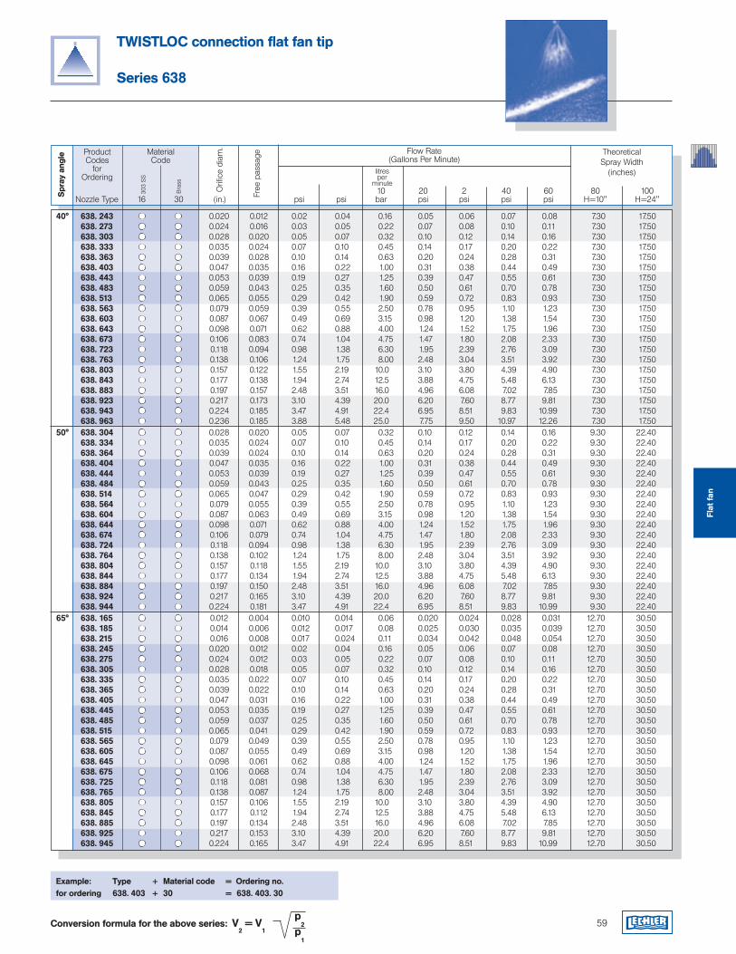
59
40° 638. 243 0.020 0.012 0.02 0.04 0.16 0.05 0.06 0.07 0.08 7.30 17.50 638. 273 0.024 0.016 0.03 0.05 0.22 0.07 0.08 0.10 0.11 7.30 17.50 638. 303 0.028 0.020 0.05 0.07 0.32 0.10 0.12 0.14 0.16 7.30 17.50 638. 333 0.035 0.024 0.07 0.10 0.45 0.14 0.17 0.20 0.22 7.30 17.50 638. 363 0.039 0.028 0.10 0.14 0.63 0.20 0.24 0.28 0.31 7.30 17.50 638. 403 0.047 0.035 0.16 0.22 1.00 0.31 0.38 0.44 0.49 7.30 17.50 638. 443 0.053 0.039 0.19 0.27 1.25 0.39 0.47 0.55 0.61 7.30 17.50 638. 483 0.059 0.043 0.25 0.35 1.60 0.50 0.61 0.70 0.78 7.30 17.50 638. 513 0.065 0.055 0.29 0.42 1.90 0.59 0.72 0.83 0.93 7.30 17.50 638. 563 0.079 0.059 0.39 0.55 2.50 0.78 0.95 1.10 1.23 7.30 17.50 638. 603 0.087 0.067 0.49 0.69 3.15 0.98 1.20 1.38 1.54 7.30 17.50 638. 643 0.098 0.071 0.62 0.88 4.00 1.24 1.52 1.75 1.96 7.30 17.50 638. 673 0.106 0.083 0.74 1.04 4.75 1.47 1.80 2.08 2.33 7.30 17.50 638. 723 0.118 0.094 0.98 1.38 6.30 1.95 2.39 2.76 3.09 7.30 17.50 638. 763 0.138 0.106 1.24 1.75 8.00 2.48 3.04 3.51 3.92 7.30 17.50 638. 803 0.157 0.122 1.55 2.19 10.0 3.10 3.80 4.39 4.90 7.30 17.50 638. 843 0.177 0.138 1.94 2.74 12.5 3.88 4.75 5.48 6.13 7.30 17.50 638. 883 0.197 0.157 2.48 3.51 16.0 4.96 6.08 7.02 7.85 7.30 17.50 638. 923 0.217 0.173 3.10 4.39 20.0 6.20 7.60 8.77 9.81 7.30 17.50 638. 943 0.224 0.185 3.47 4.91 22.4 6.95 8.51 9.83 10.99 7.30 17.50 638. 963 0.236 0.185 3.88 5.48 25.0 7.75 9.50 10.97 12.26 7.30 17.50 50° 638. 304 0.028 0.020 0.05 0.07 0.32 0.10 0.12 0.14 0.16 9.30 22.40 638. 334 0.035 0.024 0.07 0.10 0.45 0.14 0.17 0.20 0.22 9.30 22.40 638. 364 0.039 0.024 0.10 0.14 0.63 0.20 0.24 0.28 0.31 9.30 22.40 638. 404 0.047 0.035 0.16 0.22 1.00 0.31 0.38 0.44 0.49 9.30 22.40 638. 444 0.053 0.039 0.19 0.27 1.25 0.39 0.47 0.55 0.61 9.30 22.40 638. 484 0.059 0.043 0.25 0.35 1.60 0.50 0.61 0.70 0.78 9.30 22.40 638. 514 0.065 0.047 0.29 0.42 1.90 0.59 0.72 0.83 0.93 9.30 22.40 638. 564 0.079 0.055 0.39 0.55 2.50 0.78 0.95 1.10 1.23 9.30 22.40 638. 604 0.087 0.063 0.49 0.69 3.15 0.98 1.20 1.38 1.54 9.30 22.40 638. 644 0.098 0.071 0.62 0.88 4.00 1.24 1.52 1.75 1.96 9.30 22.40 638. 674 0.106 0.079 0.74 1.04 4.75 1.47 1.80 2.08 2.33 9.30 22.40 638. 724 0.118 0.094 0.98 1.38 6.30 1.95 2.39 2.76 3.09 9.30 22.40 638. 764 0.138 0.102 1.24 1.75 8.00 2.48 3.04 3.51 3.92 9.30 22.40 638. 804 0.157 0.118 1.55 2.19 10.0 3.10 3.80 4.39 4.90 9.30 22.40 638. 844 0.177 0.134 1.94 2.74 12.5 3.88 4.75 5.48 6.13 9.30 22.40 638. 884 0.197 0.150 2.48 3.51 16.0 4.96 6.08 7.02 7.85 9.30 22.40 638. 924 0.217 0.165 3.10 4.39 20.0 6.20 7.60 8.77 9.81 9.30 22.40 638. 944 0.224 0.181 3.47 4.91 22.4 6.95 8.51 9.83 10.99 9.30 22.40 65° 638. 165 0.012 0.004 0.010 0.014 0.06 0.020 0.024 0.028 0.031 12.70 30.50 638. 185 0.014 0.006 0.012 0.017 0.08 0.025 0.030 0.035 0.039 12.70 30.50 638. 215 0.016 0.008 0.017 0.024 0.11 0.034 0.042 0.048 0.054 12.70 30.50 638. 245 0.020 0.012 0.02 0.04 0.16 0.05 0.06 0.07 0.08 12.70 30.50 638. 275 0.024 0.012 0.03 0.05 0.22 0.07 0.08 0.10 0.11 12.70 30.50 638. 305 0.028 0.018 0.05 0.07 0.32 0.10 0.12 0.14 0.16 12.70 30.50 638. 335 0.035 0.022 0.07 0.10 0.45 0.14 0.17 0.20 0.22 12.70 30.50 638. 365 0.039 0.022 0.10 0.14 0.63 0.20 0.24 0.28 0.31 12.70 30.50 638. 405 0.047 0.031 0.16 0.22 1.00 0.31 0.38 0.44 0.49 12.70 30.50 638. 445 0.053 0.035 0.19 0.27 1.25 0.39 0.47 0.55 0.61 12.70 30.50 638. 485 0.059 0.037 0.25 0.35 1.60 0.50 0.61 0.70 0.78 12.70 30.50 638. 515 0.065 0.041 0.29 0.42 1.90 0.59 0.72 0.83 0.93 12.70 30.50 638. 565 0.079 0.049 0.39 0.55 2.50 0.78 0.95 1.10 1.23 12.70 30.50 638. 605 0.087 0.055 0.49 0.69 3.15 0.98 1.20 1.38 1.54 12.70 30.50 638. 645 0.098 0.061 0.62 0.88 4.00 1.24 1.52 1.75 1.96 12.70 30.50 638. 675 0.106 0.068 0.74 1.04 4.75 1.47 1.80 2.08 2.33 12.70 30.50 638. 725 0.118 0.081 0.98 1.38 6.30 1.95 2.39 2.76 3.09 12.70 30.50 638. 765 0.138 0.087 1.24 1.75 8.00 2.48 3.04 3.51 3.92 12.70 30.50 638. 805 0.157 0.106 1.55 2.19 10.0 3.10 3.80 4.39 4.90 12.70 30.50 638. 845 0.177 0.112 1.94 2.74 12.5 3.88 4.75 5.48 6.13 12.70 30.50 638. 885 0.197 0.134 2.48 3.51 16.0 4.96 6.08 7.02 7.85 12.70 30.50 638. 925 0.217 0.153 3.10 4.39 20.0 6.20 7.60 8.77 9.81 12.70 30.50 638. 945 0.224 0.165 3.47 4.91 22.4 6.95 8.51 9.83 10.99 12.70 30.50
TWISTLOC connection flat fan tip
Series 638
Conversion formula for the above series: V2 = V
1
p2
p1
ProductCodes
for Ordering
Flow Rate(Gallons Per Minute)
TheoreticalSpray Width
(inches)
10 20 2 40 60 80 100 Nozzle Type 16 30 (in.) psi psi bar psi psi psi psi H=10" H=24"
MaterialCode
303
SS
litresper
minute
Orifi
ce d
iam
.
Spr
ay a
ngle
Bra
ss
Free
pas
sage
Example: Type + Material code = Ordering no.for ordering 638. 403 + 30 = 638. 403. 30
Flat
fan
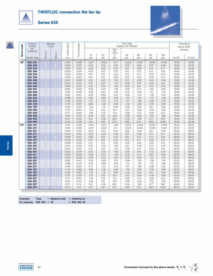
60
TWISTLOC connection flat fan tip
Series 638
Conversion formula for the above series: V2 = V
1
p2
p1
ProductCodes
for Ordering
Flow Rate(Gallons Per Minute)
TheoreticalSpray Width
(inches)
10 20 2 40 60 80 100 Nozzle Type 16 30 (in.) psi psi bar psi psi psi psi H=10" H=24"
MaterialCode
303
SS
litresper
minute
Orifi
ce d
iam
.
Spr
ay a
ngle
Bra
ss
Free
pas
sage
Example: Type + Material code = Ordering no.for ordering 638. 403 + 30 = 638. 403. 30
Flat
fan
80° 638. 216 0.016 0.008 0.017 0.024 0.11 0.034 0.042 0.048 0.054 16.80 40.30 638. 246 0.020 0.010 0.02 0.04 0.16 0.05 0.06 0.07 0.08 16.80 40.30 638. 276 0.024 0.012 0.03 0.05 0.22 0.07 0.08 0.10 0.11 16.80 40.30 638. 306 0.028 0.016 0.05 0.07 0.32 0.10 0.12 0.14 0.16 16.80 40.30 638. 336 0.035 0.020 0.07 0.10 0.45 0.14 0.17 0.20 0.22 16.80 40.30 638. 366 0.039 0.022 0.10 0.14 0.63 0.20 0.24 0.28 0.31 16.80 40.30 638. 406 0.047 0.028 0.16 0.22 1.00 0.31 0.38 0.44 0.49 16.80 40.30 638. 446 0.053 0.031 0.19 0.27 1.25 0.39 0.47 0.55 0.61 16.80 40.30 638. 486 0.059 0.031 0.25 0.35 1.60 0.50 0.61 0.70 0.78 16.80 40.30 638. 516 0.065 0.035 0.29 0.42 1.90 0.59 0.72 0.83 0.93 16.80 40.30 638. 566 0.079 0.043 0.39 0.55 2.50 0.78 0.95 1.10 1.23 16.80 40.30 638. 606 0.087 0.047 0.49 0.69 3.15 0.98 1.20 1.38 1.54 16.80 40.30 638. 646 0.098 0.051 0.62 0.88 4.00 1.24 1.52 1.75 1.96 16.80 40.30 638. 676 0.106 0.055 0.74 1.04 4.75 1.47 1.80 2.08 2.33 16.80 40.30 638. 726 0.118 0.067 0.98 1.38 6.30 1.95 2.39 2.76 3.09 16.80 40.30 638. 766 0.138 0.075 1.24 1.75 8.00 2.48 3.04 3.51 3.92 16.80 40.30 638. 806 0.157 0.094 1.55 2.19 10.0 3.10 3.80 4.39 4.90 16.80 40.30 638. 846 0.177 0.094 1.94 2.74 12.5 3.88 4.75 5.48 6.13 16.80 40.30 638. 886 0.197 0.122 2.48 3.51 16.0 4.96 6.08 7.02 7.85 16.80 40.30 638. 926 0.217 0.142 3.10 4.39 20.0 6.20 7.60 8.77 9.81 16.80 40.30 638. 946 0.224 0.150 3.47 4.91 22.4 6.95 8.51 9.83 10.99 16.80 40.30 110° 638. 187 0.014 0.008 0.012 0.017 0.08 0.025 0.030 0.035 0.039 28.50 68.50 638. 217 0.016 0.008 0.017 0.024 0.11 0.034 0.042 0.048 0.054 28.50 68.50 638. 247 0.020 0.010 0.02 0.04 0.16 0.05 0.06 0.07 0.08 28.50 68.50 638. 277 0.024 0.012 0.03 0.05 0.22 0.07 0.08 0.10 0.11 28.50 68.50 638. 307 0.028 0.012 0.05 0.07 0.32 0.10 0.12 0.14 0.16 28.50 68.50 638. 337 0.035 0.016 0.07 0.10 0.45 0.14 0.17 0.20 0.22 28.50 68.50 638. 367 0.039 0.020 0.10 0.14 0.63 0.20 0.24 0.28 0.31 28.50 68.50 638. 407 0.047 0.024 0.16 0.22 1.00 0.31 0.38 0.44 0.49 28.50 68.50 638. 447 0.053 0.027 0.19 0.27 1.25 0.39 0.47 0.55 0.61 28.50 68.50 638. 487 0.059 0.029 0.25 0.35 1.60 0.50 0.61 0.70 0.78 28.50 68.50 638. 517 0.065 0.035 0.29 0.42 1.90 0.59 0.72 0.83 0.93 28.50 68.50 638. 567 0.079 0.039 0.39 0.55 2.50 0.78 0.95 1.10 1.23 28.50 68.50 638. 607 0.087 0.041 0.49 0.69 3.15 0.98 1.20 1.38 1.54 28.50 68.50 638. 647 0.098 0.043 0.62 0.88 4.00 1.24 1.52 1.75 1.96 28.50 68.50 638. 677 0.106 0.055 0.74 1.04 4.75 1.47 1.80 2.08 2.33 28.50 68.50 638. 727 0.118 0.063 0.98 1.38 6.30 1.95 2.39 2.76 3.09 28.50 68.50 638. 767 0.138 0.067 1.24 1.75 8.00 2.48 3.04 3.51 3.92 28.50 68.50 638. 807 0.157 0.079 1.55 2.19 10.0 3.10 3.80 4.39 4.90 28.50 68.50 638. 847 0.177 0.091 1.94 2.74 12.5 3.88 4.75 5.48 6.13 28.50 68.50 638. 887 0.197 0.102 2.48 3.51 16.0 4.96 6.08 7.02 7.85 28.50 68.50 638. 927 0.217 0.114 3.10 4.39 20.0 6.20 7.60 8.77 9.81 28.50 68.50 638. 947 0.224 0.13 3.47 4.91 22.4 6.95 8.51 9.83 10.99 28.50 68.50
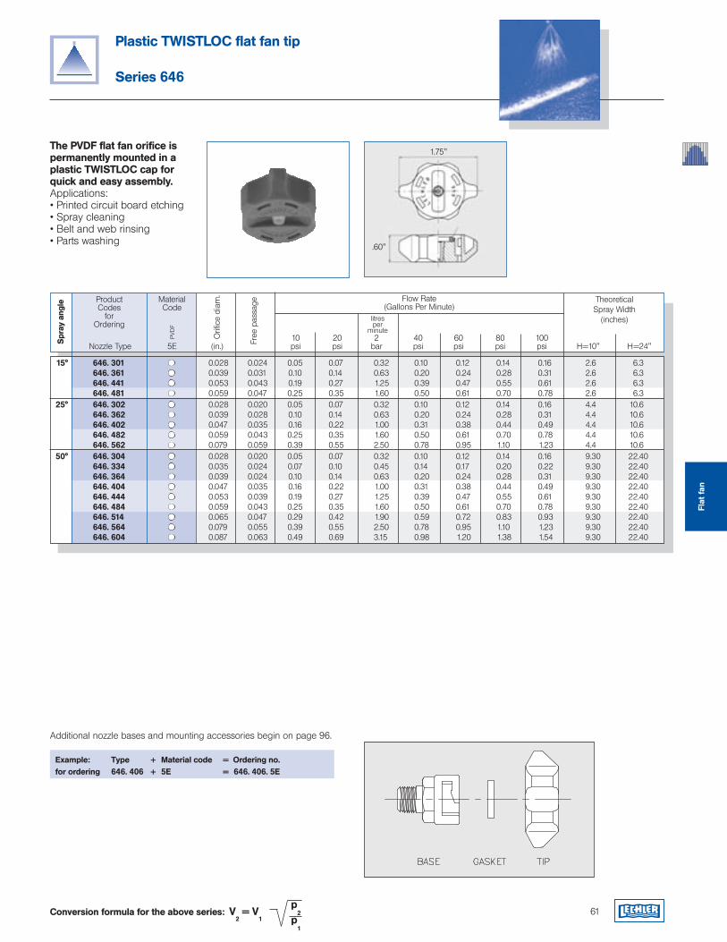
61
Plastic TWISTLOC flat fan tip
Series 646
The PVDF flat fan orifice is permanently mounted in a plastic TWISTLOC cap for quick and easy assembly.Applications:• Printed circuit board etching• Spray cleaning• Belt and web rinsing• Parts washing
ProductCodes
for Ordering
Flow Rate(Gallons Per Minute)
TheoreticalSpray Width
(inches)
10 20 2 40 60 80 100 Nozzle Type 5E (in.) psi psi bar psi psi psi psi H=10" H=24"
MaterialCode
litresper
minute
Orifi
ce d
iam
.
Spr
ay a
ngle
PVD
F
Free
pas
sage
Example: Type + Material code = Ordering no.for ordering 646. 406 + 5E = 646. 406. 5E
Additional nozzle bases and mounting accessories begin on page 96.
Conversion formula for the above series: V2 = V
1
p2
p1
1.75"
.60"
15° 646. 301 0.028 0.024 0.05 0.07 0.32 0.10 0.12 0.14 0.16 2.6 6.3 646. 361 0.039 0.031 0.10 0.14 0.63 0.20 0.24 0.28 0.31 2.6 6.3 646. 441 0.053 0.043 0.19 0.27 1.25 0.39 0.47 0.55 0.61 2.6 6.3 646. 481 0.059 0.047 0.25 0.35 1.60 0.50 0.61 0.70 0.78 2.6 6.3 25° 646. 302 0.028 0.020 0.05 0.07 0.32 0.10 0.12 0.14 0.16 4.4 10.6 646. 362 0.039 0.028 0.10 0.14 0.63 0.20 0.24 0.28 0.31 4.4 10.6 646. 402 0.047 0.035 0.16 0.22 1.00 0.31 0.38 0.44 0.49 4.4 10.6 646. 482 0.059 0.043 0.25 0.35 1.60 0.50 0.61 0.70 0.78 4.4 10.6 646. 562 0.079 0.059 0.39 0.55 2.50 0.78 0.95 1.10 1.23 4.4 10.6 50° 646. 304 0.028 0.020 0.05 0.07 0.32 0.10 0.12 0.14 0.16 9.30 22.40 646. 334 0.035 0.024 0.07 0.10 0.45 0.14 0.17 0.20 0.22 9.30 22.40 646. 364 0.039 0.024 0.10 0.14 0.63 0.20 0.24 0.28 0.31 9.30 22.40 646. 404 0.047 0.035 0.16 0.22 1.00 0.31 0.38 0.44 0.49 9.30 22.40 646. 444 0.053 0.039 0.19 0.27 1.25 0.39 0.47 0.55 0.61 9.30 22.40 646. 484 0.059 0.043 0.25 0.35 1.60 0.50 0.61 0.70 0.78 9.30 22.40 646. 514 0.065 0.047 0.29 0.42 1.90 0.59 0.72 0.83 0.93 9.30 22.40 646. 564 0.079 0.055 0.39 0.55 2.50 0.78 0.95 1.10 1.23 9.30 22.40 646. 604 0.087 0.063 0.49 0.69 3.15 0.98 1.20 1.38 1.54 9.30 22.40
Flat
fan
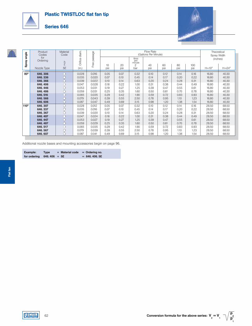
62
Plastic TWISTLOC flat fan tip
Series 646
ProductCodes
for Ordering
Flow Rate(Gallons Per Minute)
TheoreticalSpray Width
(inches)
10 20 2 40 60 80 100 Nozzle Type 5E (in.) psi psi bar psi psi psi psi H=10" H=24"
MaterialCode
litresper
minute
Orifi
ce d
iam
.
Spr
ay a
ngle
PVD
F
Free
pas
sage
Conversion formula for the above series: V2 = V
1
p2
p1
Example: Type + Material code = Ordering no.for ordering 646. 406 + 5E = 646. 406. 5E
Additional nozzle bases and mounting accessories begin on page 96.
80° 646. 306 0.028 0.016 0.05 0.07 0.32 0.10 0.12 0.14 0.16 16.80 40.30 646. 336 0.035 0.020 0.07 0.10 0.45 0.14 0.17 0.20 0.22 16.80 40.30 646. 366 0.039 0.022 0.10 0.14 0.63 0.20 0.24 0.28 0.31 16.80 40.30 646. 406 0.047 0.028 0.16 0.22 1.00 0.31 0.38 0.44 0.49 16.80 40.30 646. 446 0.053 0.031 0.19 0.27 1.25 0.39 0.47 0.55 0.61 16.80 40.30 646. 486 0.059 0.031 0.25 0.35 1.60 0.50 0.61 0.70 0.78 16.80 40.30 646. 516 0.065 0.035 0.29 0.42 1.90 0.59 0.72 0.83 0.93 16.80 40.30 646. 566 0.079 0.043 0.39 0.55 2.50 0.78 0.95 1.10 1.23 16.80 40.30 646. 606 0.087 0.047 0.49 0.69 3.15 0.98 1.20 1.38 1.54 16.80 40.30 110° 646. 307 0.028 0.012 0.05 0.07 0.32 0.10 0.12 0.14 0.16 28.50 68.50 646. 337 0.035 0.016 0.07 0.10 0.45 0.14 0.17 0.20 0.22 28.50 68.50 646. 367 0.039 0.020 0.10 0.14 0.63 0.20 0.24 0.28 0.31 28.50 68.50 646. 407 0.047 0.024 0.16 0.22 1.00 0.31 0.38 0.44 0.49 28.50 68.50 646. 447 0.053 0.027 0.19 0.27 1.25 0.39 0.47 0.55 0.61 28.50 68.50 646. 487 0.059 0.029 0.25 0.35 1.60 0.50 0.61 0.70 0.78 28.50 68.50 646. 517 0.065 0.035 0.29 0.42 1.90 0.59 0.72 0.83 0.93 28.50 68.50 646. 567 0.079 0.039 0.39 0.55 2.50 0.78 0.95 1.10 1.23 28.50 68.50 646. 607 0.087 0.041 0.49 0.69 3.15 0.98 1.20 1.38 1.54 28.50 68.50
Flat
fan
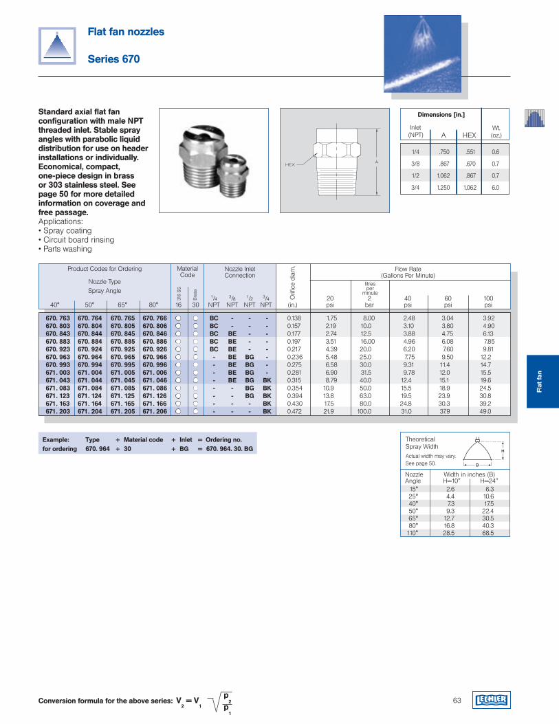
Theoretical Spray WidthActual width may vary.See page 50.
H
B
Nozzle Width in inches (B)Angle H=10" H=24" 15° 2.6 6.3 25° 4.4 10.6 40° 7.3 17.5 50° 9.3 22.4 65° 12.7 30.5 80° 16.8 40.3110° 28.5 68.5
670. 763 670. 764 670. 765 670. 766 BC - - - 0.138 1.75 8.00 2.48 3.04 3.92 670. 803 670. 804 670. 805 670. 806 BC - - - 0.157 2.19 10.0 3.10 3.80 4.90 670. 843 670. 844 670. 845 670. 846 BC BE - - 0.177 2.74 12.5 3.88 4.75 6.13 670. 883 670. 884 670. 885 670. 886 BC BE - - 0.197 3.51 16.00 4.96 6.08 7.85 670. 923 670. 924 670. 925 670. 926 BC BE - - 0.217 4.39 20.0 6.20 7.60 9.81 670. 963 670. 964 670. 965 670. 966 - BE BG - 0.236 5.48 25.0 7.75 9.50 12.2 670. 993 670. 994 670. 995 670. 996 - BE BG - 0.275 6.58 30.0 9.31 11.4 14.7 671. 003 671. 004 671. 005 671. 006 - BE BG - 0.281 6.90 31.5 9.78 12.0 15.5 671. 043 671. 044 671. 045 671. 046 - BE BG BK 0.315 8.79 40.0 12.4 15.1 19.6 671. 083 671. 084 671. 085 671. 086 - - BG BK 0.354 10.9 50.0 15.5 18.9 24.5 671. 123 671. 124 671. 125 671. 126 - - BG BK 0.394 13.8 63.0 19.5 23.9 30.8 671. 163 671. 164 671. 165 671. 166 - - - BK 0.430 17.5 80.0 24.8 30.3 39.2 671. 203 671. 204 671. 205 671. 206 - - - BK 0.472 21.9 100.0 31.0 37.9 49.0
63
Standard axial flat fan configuration with male NPT threaded inlet. Stable spray angles with parabolic liquid distribution for use on header installations or individually. Economical, compact, one-piece design in brass or 303 stainless steel. See page 50 for more detailed information on coverage and free passage.Applications:• Spray coating• Circuit board rinsing• Parts washing
Flat fan nozzles
Series 670
Conversion formula for the above series: V2 = V
1
p2
p1
Example: Type + Material code + Inlet = Ordering no.for ordering 670. 964 + 30 + BG = 670. 964. 30. BG
Dimensions [in.]
A HEX Inlet(NPT)
Wt.(oz.)
1/4 .750 .551 0.6
3/8 .867 .670 0.7
1/2 1.062 .867 0.7
3/4 1.250 1.062 6.0
Product Codes for Ordering
Nozzle TypeSpray Angle
Flow Rate(Gallons Per Minute)
1/4 3/8 1/2 3/4 20 2 40 60 100 40° 50° 65° 80° 16 30 NPT NPT NPT NPT (in.) psi bar psi psi psi
MaterialCode
316
SS
litresper
minute
Nozzle Inlet Connection
Orifi
ce d
iam
.
Bra
ss
Flat
fan
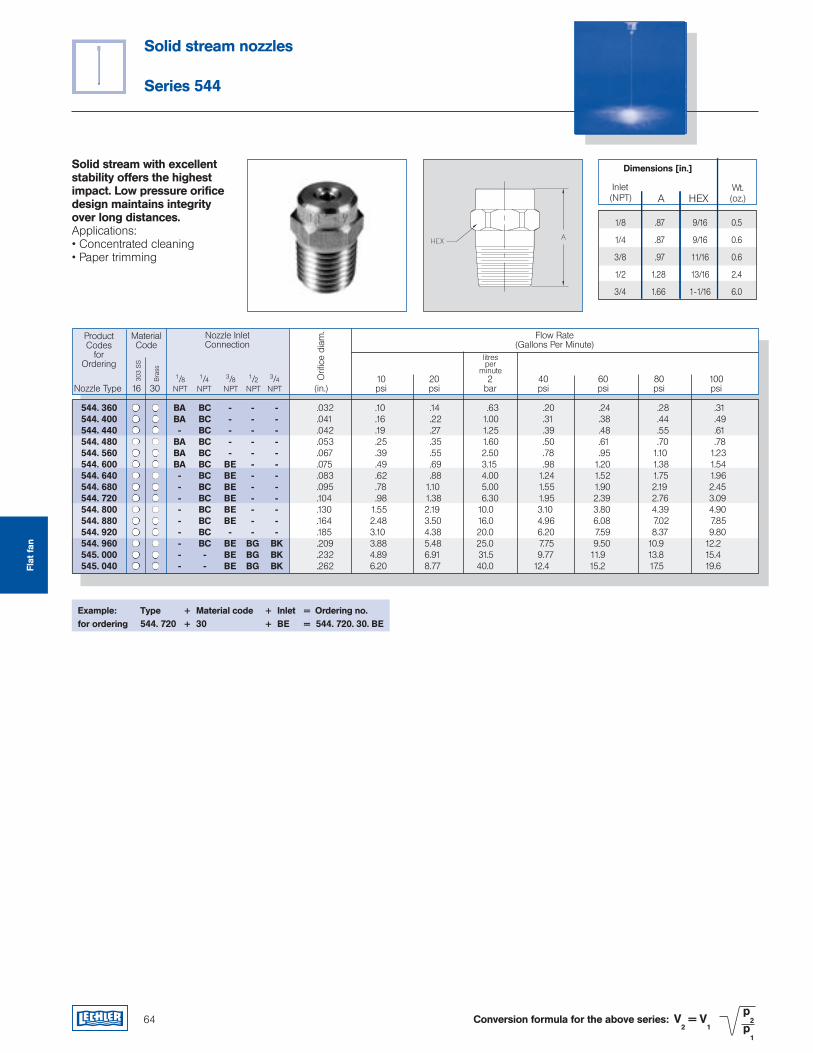
64
Solid stream nozzles
Series 544
Conversion formula for the above series: V2 = V
1
p2
p1
Solid stream with excellent stability offers the highest impact. Low pressure orifice design maintains integrity over long distances.Applications:• Concentrated cleaning• Paper trimming
Dimensions [in.]
A HEX Inlet(NPT)
Wt.(oz.)
1/8 .87 9/16 0.5
1/4 .87 9/16 0.6
3/8 .97 11/16 0.6
1/2 1.28 13/16 2.4
3/4 1.66 1-1/16 6.0
ProductCodes
for Ordering
Flow Rate(Gallons Per Minute)
1/8 1/4 3/8 1/2 3/4 10 20 2 40 60 80 100 Nozzle Type 16 30 NPT NPT NPT NPT NPT (in.) psi psi bar psi psi psi psi
MaterialCode
303
SS
litresper
minute
Nozzle Inlet Connection
Orifi
ce d
iam
.
Bra
ss
Example: Type + Material code + Inlet = Ordering no.for ordering 544. 720 + 30 + BE = 544. 720. 30. BE
Flat
fan
544. 360 BA BC - - - .032 .10 .14 .63 .20 .24 .28 .31 544. 400 BA BC - - - .041 .16 .22 1.00 .31 .38 .44 .49 544. 440 - BC - - - .042 .19 .27 1.25 .39 .48 .55 .61 544. 480 BA BC - - - .053 .25 .35 1.60 .50 .61 .70 .78 544. 560 BA BC - - - .067 .39 .55 2.50 .78 .95 1.10 1.23 544. 600 BA BC BE - - .075 .49 .69 3.15 .98 1.20 1.38 1.54 544. 640 - BC BE - - .083 .62 .88 4.00 1.24 1.52 1.75 1.96 544. 680 - BC BE - - .095 .78 1.10 5.00 1.55 1.90 2.19 2.45 544. 720 - BC BE - - .104 .98 1.38 6.30 1.95 2.39 2.76 3.09 544. 800 - BC BE - - .130 1.55 2.19 10.0 3.10 3.80 4.39 4.90 544. 880 - BC BE - - .164 2.48 3.50 16.0 4.96 6.08 7.02 7.85 544. 920 - BC - - - .185 3.10 4.38 20.0 6.20 7.59 8.37 9.80 544. 960 - BC BE BG BK .209 3.88 5.48 25.0 7.75 9.50 10.9 12.2 545. 000 - - BE BG BK .232 4.89 6.91 31.5 9.77 11.9 13.8 15.4 545. 040 - - BE BG BK .262 6.20 8.77 40.0 12.4 15.2 17.5 19.6
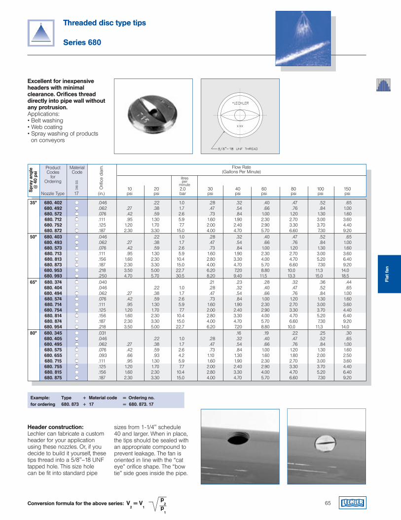
35° 680. 402 .046 .22 1.0 .28 .32 .40 .47 .52 .65 680. 492 .062 .27 .38 1.7 .47 .54 .66 .76 .84 1.00 680. 572 .076 .42 .59 2.6 .73 .84 1.00 1.20 1.30 1.60 680. 712 .111 .95 1.30 5.9 1.60 1.90 2.30 2.70 3.00 3.60 680. 752 .125 1.20 1.70 7.7 2.00 2.40 2.90 3.30 3.70 4.40 680. 872 .187 2.30 3.30 15.0 4.00 4.70 5.70 6.60 7.30 9.20 50° 680. 403 .046 .22 1.0 .28 .32 .40 .47 .52 .65 680. 493 .062 .27 .38 1.7 .47 .54 .66 .76 .84 1.00 680. 573 .076 .42 .59 2.6 .73 .84 1.00 1.20 1.30 1.60 680. 713 .111 .95 1.30 5.9 1.60 1.90 2.30 2.70 3.00 3.60 680. 813 .156 1.60 2.30 10.4 2.80 3.30 4.00 4.70 5.20 6.40 680. 873 .187 2.30 3.30 15.0 4.00 4.70 5.70 6.60 7.30 9.20 680. 953 .218 3.50 5.00 22.7 6.20 7.20 8.80 10.0 11.3 14.0 680. 993 .250 4.70 5.70 30.5 8.20 9.40 11.5 13.3 15.0 18.5 65° 680. 374 .040 .21 .23 .28 .32 .36 .44 680. 404 .046 .22 1.0 .28 .32 .40 .47 .52 .65 680. 494 .062 .27 .38 1.7 .47 .54 .66 .76 .84 1.00 680. 574 .076 .42 .59 2.6 .73 .84 1.00 1.20 1.30 1.60 680. 714 .111 .95 1.30 5.9 1.60 1.90 2.30 2.70 3.00 3.60 680. 754 .125 1.20 1.70 7.7 2.00 2.40 2.90 3.30 3.70 4.40 680. 814 .156 1.60 2.30 10.4 2.80 3.30 4.00 4.70 5.20 6.40 680. 874 .187 2.30 3.30 15.0 4.00 4.70 5.70 6.60 7.30 9.20 680. 954 .218 3.50 5.00 22.7 6.20 7.20 8.80 10.0 11.3 14.0 80° 680. 345 .031 .16 .19 .22 .25 .30 680. 405 .046 .22 1.0 .28 .32 .40 .47 .52 .65 680. 495 .062 .27 .38 1.7 .47 .54 .66 .76 .84 1.00 680. 575 .076 .42 .59 2.6 .73 .84 1.00 1.20 1.30 1.60 680. 655 .093 .66 .93 4.2 1.10 1.30 1.60 1.80 2.00 2.50 680. 715 .111 .95 1.30 5.9 1.60 1.90 2.30 2.70 3.00 3.60 680. 755 .125 1.20 1.70 7.7 2.00 2.40 2.90 3.30 3.70 4.40 680. 815 .156 1.60 2.30 10.4 2.80 3.30 4.00 4.70 5.20 6.40 680. 875 .187 2.30 3.30 15.0 4.00 4.70 5.70 6.60 7.30 9.20
Threaded disc type tips
Series 680
Excellent for inexpensive headers with minimal clearance. Orifices thread directly into pipe wall without any protrusion.Applications:• Belt washing• Web coating• Spray washing of products on conveyors
Example: Type + Material code = Ordering no.for ordering 680. 873 + 17 = 680. 873. 17
ProductCodes
for Ordering
Flow Rate(Gallons Per Minute)
10 20 2.0 30 40 60 80 100 150 Nozzle Type 17 (in.) psi psi bar psi psi psi psi psi psi
MaterialCode
316
SS
litresper
minute
Orifi
ce d
iam
.
Spr
ay a
ngle
@
40
psi
65Conversion formula for the above series: V2 = V
1
p2
p1
Header construction:Lechler can fabricate a custom header for your application using these nozzles. Or, if you decide to build it yourself, these tips thread into a 5/8"–18 UNF tapped hole. This size hole can be fit into standard pipe
sizes from 1-1/4" schedule 40 and larger. When in place, the tips should be sealed with an appropriate compound to prevent leakage. The fan is oriented in line with the “cat eye” orifice shape. The “bow tie” side goes inside the pipe.
Flat
fan
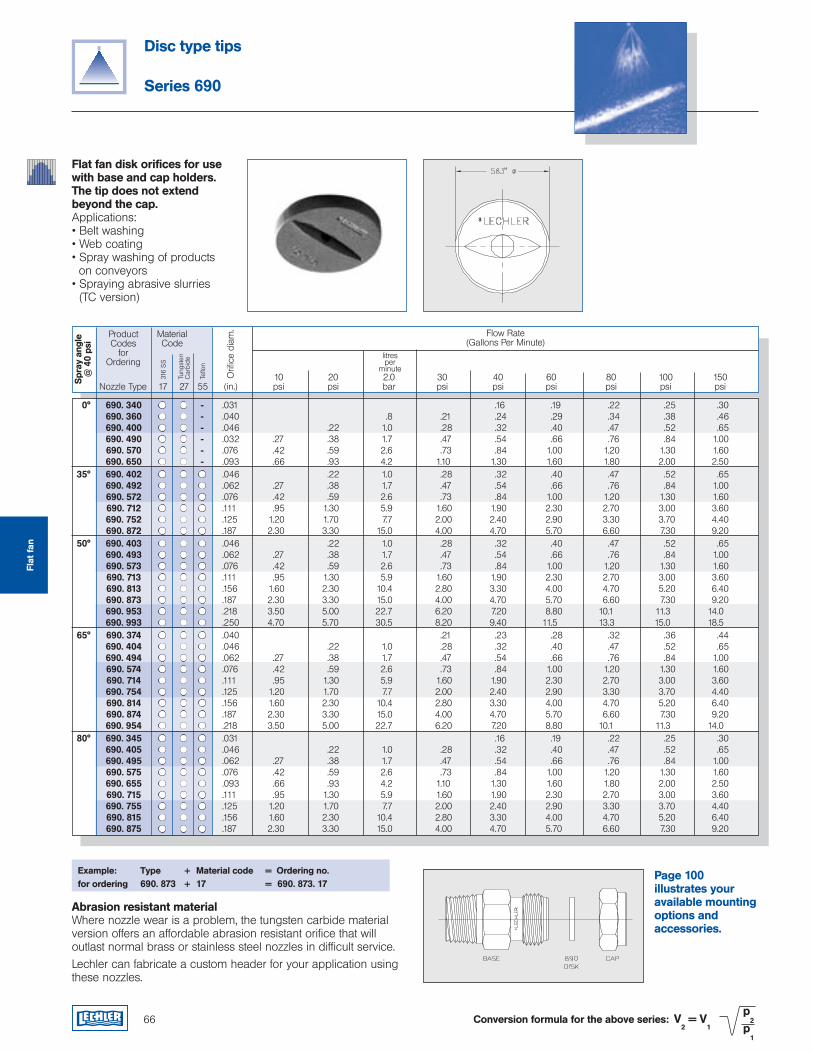
Disc type tips
Series 690
Flat fan disk orifices for use with base and cap holders. The tip does not extend beyond the cap. Applications:• Belt washing• Web coating• Spray washing of products on conveyors• Spraying abrasive slurries (TC version)
Example: Type + Material code = Ordering no.for ordering 690. 873 + 17 = 690. 873. 17
ProductCodes
for Ordering
Flow Rate(Gallons Per Minute)
10 20 2.0 30 40 60 80 100 150 Nozzle Type 17 27 55 (in.) psi psi bar psi psi psi psi psi psi
MaterialCode
316
SS
litresper
minute
Orifi
ce d
iam
.
Spr
ay a
ngle
@
40
psi
Abrasion resistant materialWhere nozzle wear is a problem, the tungsten carbide material version offers an affordable abrasion resistant orifice that will outlast normal brass or stainless steel nozzles in difficult service.Lechler can fabricate a custom header for your application using these nozzles.
66 Conversion formula for the above series: V2 = V
1
p2
p1
0° 690. 340 - .031 .16 .19 .22 .25 .30 690. 360 - .040 .8 .21 .24 .29 .34 .38 .46 690. 400 - .046 .22 1.0 .28 .32 .40 .47 .52 .65 690. 490 - .032 .27 .38 1.7 .47 .54 .66 .76 .84 1.00 690. 570 - .076 .42 .59 2.6 .73 .84 1.00 1.20 1.30 1.60 690. 650 - .093 .66 .93 4.2 1.10 1.30 1.60 1.80 2.00 2.50 35° 690. 402 .046 .22 1.0 .28 .32 .40 .47 .52 .65 690. 492 .062 .27 .38 1.7 .47 .54 .66 .76 .84 1.00 690. 572 .076 .42 .59 2.6 .73 .84 1.00 1.20 1.30 1.60 690. 712 .111 .95 1.30 5.9 1.60 1.90 2.30 2.70 3.00 3.60 690. 752 .125 1.20 1.70 7.7 2.00 2.40 2.90 3.30 3.70 4.40 690. 872 .187 2.30 3.30 15.0 4.00 4.70 5.70 6.60 7.30 9.20 50° 690. 403 .046 .22 1.0 .28 .32 .40 .47 .52 .65 690. 493 .062 .27 .38 1.7 .47 .54 .66 .76 .84 1.00 690. 573 .076 .42 .59 2.6 .73 .84 1.00 1.20 1.30 1.60 690. 713 .111 .95 1.30 5.9 1.60 1.90 2.30 2.70 3.00 3.60 690. 813 .156 1.60 2.30 10.4 2.80 3.30 4.00 4.70 5.20 6.40 690. 873 .187 2.30 3.30 15.0 4.00 4.70 5.70 6.60 7.30 9.20 690. 953 .218 3.50 5.00 22.7 6.20 7.20 8.80 10.1 11.3 14.0 690. 993 .250 4.70 5.70 30.5 8.20 9.40 11.5 13.3 15.0 18.5 65° 690. 374 .040 .21 .23 .28 .32 .36 .44 690. 404 .046 .22 1.0 .28 .32 .40 .47 .52 .65 690. 494 .062 .27 .38 1.7 .47 .54 .66 .76 .84 1.00 690. 574 .076 .42 .59 2.6 .73 .84 1.00 1.20 1.30 1.60 690. 714 .111 .95 1.30 5.9 1.60 1.90 2.30 2.70 3.00 3.60 690. 754 .125 1.20 1.70 7.7 2.00 2.40 2.90 3.30 3.70 4.40 690. 814 .156 1.60 2.30 10.4 2.80 3.30 4.00 4.70 5.20 6.40 690. 874 .187 2.30 3.30 15.0 4.00 4.70 5.70 6.60 7.30 9.20 690. 954 .218 3.50 5.00 22.7 6.20 7.20 8.80 10.1 11.3 14.0 80° 690. 345 .031 .16 .19 .22 .25 .30 690. 405 .046 .22 1.0 .28 .32 .40 .47 .52 .65 690. 495 .062 .27 .38 1.7 .47 .54 .66 .76 .84 1.00 690. 575 .076 .42 .59 2.6 .73 .84 1.00 1.20 1.30 1.60 690. 655 .093 .66 .93 4.2 1.10 1.30 1.60 1.80 2.00 2.50 690. 715 .111 .95 1.30 5.9 1.60 1.90 2.30 2.70 3.00 3.60 690. 755 .125 1.20 1.70 7.7 2.00 2.40 2.90 3.30 3.70 4.40 690. 815 .156 1.60 2.30 10.4 2.80 3.30 4.00 4.70 5.20 6.40 690. 875 .187 2.30 3.30 15.0 4.00 4.70 5.70 6.60 7.30 9.20
Tung
sten
Car
bide
Teflo
n
Page 100 illustrates your available mounting options and accessories.
Flat
fan
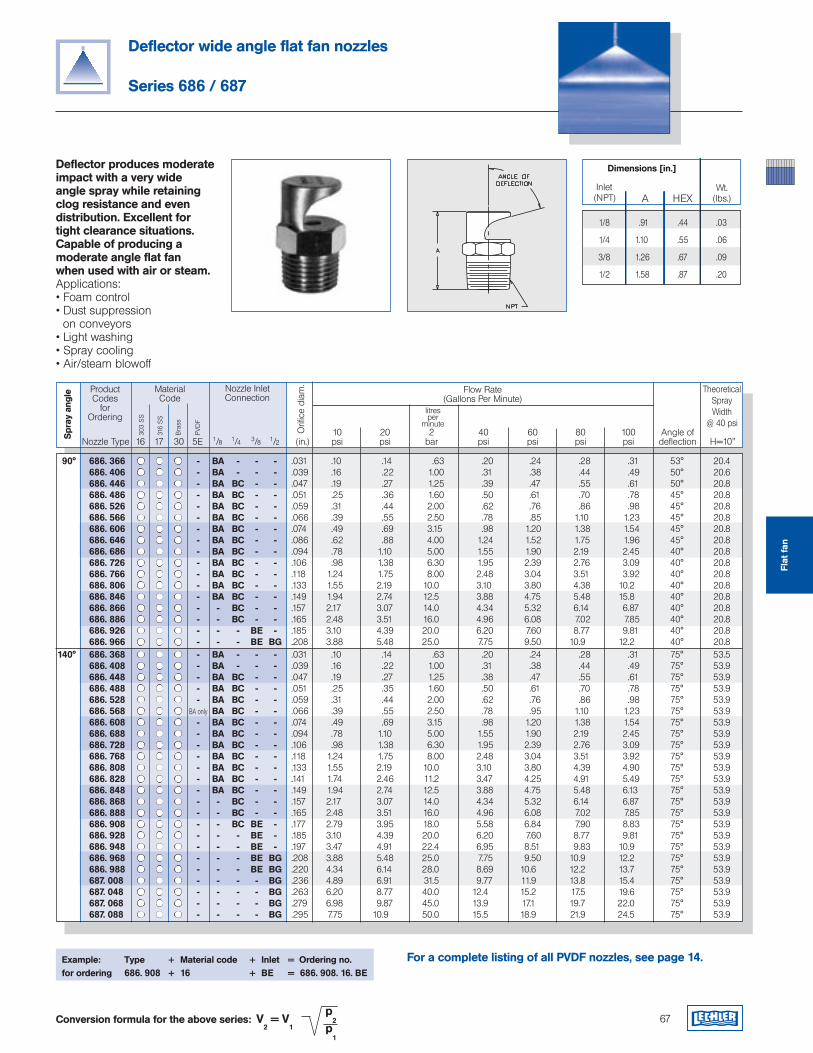
Deflector wide angle flat fan nozzles
Series 686 / 687
Deflector produces moderate impact with a very wide angle spray while retaining clog resistance and even distribution. Excellent for tight clearance situations. Capable of producing a moderate angle flat fan when used with air or steam.Applications:• Foam control• Dust suppression on conveyors• Light washing• Spray cooling• Air/steam blowoff
67Conversion formula for the above series: V2 = V
1
p2
p1
ProductCodes
for Ordering
Flow Rate(Gallons Per Minute)
TheoreticalSpray Width
@ 40 psi 10 20 2 40 60 80 100 Angle of Nozzle Type 16 17 30 5E 1/8 1/4 3/8 1/2 (in.) psi psi bar psi psi psi psi deflection H=10"
MaterialCode
303
SS
316
SS
litresper
minute
Nozzle Inlet Connection
Orifi
ce d
iam
.
Spr
ay a
ngle
Bra
ss
Example: Type + Material code + Inlet = Ordering no.for ordering 686. 908 + 16 + BE = 686. 908. 16. BE
Dimensions [in.]
A HEX Inlet(NPT)
Wt.(lbs.)
1/8 .91 .44 .03
1/4 1.10 .55 .06
3/8 1.26 .67 .09
1/2 1.58 .87 .20
PVD
F
For a complete listing of all PVDF nozzles, see page 14.
Flat
fan
90° 686. 366 - BA - - - .031 .10 .14 .63 .20 .24 .28 .31 53° 20.4 686. 406 - BA - - - .039 .16 .22 1.00 .31 .38 .44 .49 50° 20.6 686. 446 - BA BC - - .047 .19 .27 1.25 .39 .47 .55 .61 50° 20.8 686. 486 - BA BC - - .051 .25 .36 1.60 .50 .61 .70 .78 45° 20.8 686. 526 - BA BC - - .059 .31 .44 2.00 .62 .76 .86 .98 45° 20.8 686. 566 - BA BC - - .066 .39 .55 2.50 .78 .85 1.10 1.23 45° 20.8 686. 606 - BA BC - - .074 .49 .69 3.15 .98 1.20 1.38 1.54 45° 20.8 686. 646 - BA BC - - .086 .62 .88 4.00 1.24 1.52 1.75 1.96 45° 20.8 686. 686 - BA BC - - .094 .78 1.10 5.00 1.55 1.90 2.19 2.45 40° 20.8 686. 726 - BA BC - - .106 .98 1.38 6.30 1.95 2.39 2.76 3.09 40° 20.8 686. 766 - BA BC - - .118 1.24 1.75 8.00 2.48 3.04 3.51 3.92 40° 20.8 686. 806 - BA BC - - .133 1.55 2.19 10.0 3.10 3.80 4.38 10.2 40° 20.8 686. 846 - BA BC - - .149 1.94 2.74 12.5 3.88 4.75 5.48 15.8 40° 20.8 686. 866 - - BC - - .157 2.17 3.07 14.0 4.34 5.32 6.14 6.87 40° 20.8 686. 886 - - BC - - .165 2.48 3.51 16.0 4.96 6.08 7.02 7.85 40° 20.8 686. 926 - - - BE - .185 3.10 4.39 20.0 6.20 7.60 8.77 9.81 40° 20.8 686. 966 - - - BE BG .208 3.88 5.48 25.0 7.75 9.50 10.9 12.2 40° 20.8 140° 686. 368 - BA - - - .031 .10 .14 .63 .20 .24 .28 .31 75° 53.5 686. 408 - BA - - - .039 .16 .22 1.00 .31 .38 .44 .49 75° 53.9 686. 448 - BA BC - - .047 .19 .27 1.25 .38 .47 .55 .61 75° 53.9 686. 488 - BA BC - - .051 .25 .35 1.60 .50 .61 .70 .78 75° 53.9 686. 528 - BA BC - - .059 .31 .44 2.00 .62 .76 .86 .98 75° 53.9 686. 568 BA only BA BC - - .066 .39 .55 2.50 .78 .95 1.10 1.23 75° 53.9 686. 608 - BA BC - - .074 .49 .69 3.15 .98 1.20 1.38 1.54 75° 53.9 686. 688 - BA BC - - .094 .78 1.10 5.00 1.55 1.90 2.19 2.45 75° 53.9 686. 728 - BA BC - - .106 .98 1.38 6.30 1.95 2.39 2.76 3.09 75° 53.9 686. 768 - BA BC - - .118 1.24 1.75 8.00 2.48 3.04 3.51 3.92 75° 53.9 686. 808 - BA BC - - .133 1.55 2.19 10.0 3.10 3.80 4.39 4.90 75° 53.9 686. 828 - BA BC - - .141 1.74 2.46 11.2 3.47 4.25 4.91 5.49 75° 53.9 686. 848 - BA BC - - .149 1.94 2.74 12.5 3.88 4.75 5.48 6.13 75° 53.9 686. 868 - - BC - - .157 2.17 3.07 14.0 4.34 5.32 6.14 6.87 75° 53.9 686. 888 - - BC - - .165 2.48 3.51 16.0 4.96 6.08 7.02 7.85 75° 53.9 686. 908 - - BC BE - .177 2.79 3.95 18.0 5.58 6.84 7.90 8.83 75° 53.9 686. 928 - - - BE - .185 3.10 4.39 20.0 6.20 7.60 8.77 9.81 75° 53.9 686. 948 - - - BE - .197 3.47 4.91 22.4 6.95 8.51 9.83 10.9 75° 53.9 686. 968 - - - BE BG .208 3.88 5.48 25.0 7.75 9.50 10.9 12.2 75° 53.9 686. 988 - - - BE BG .220 4.34 6.14 28.0 8.69 10.6 12.2 13.7 75° 53.9 687. 008 - - - - BG .236 4.89 6.91 31.5 9.77 11.9 13.8 15.4 75° 53.9 687. 048 - - - - BG .263 6.20 8.77 40.0 12.4 15.2 17.5 19.6 75° 53.9 687. 068 - - - - BG .279 6.98 9.87 45.0 13.9 17.1 19.7 22.0 75° 53.9 687. 088 - - - - BG .295 7.75 10.9 50.0 15.5 18.9 21.9 24.5 75° 53.9
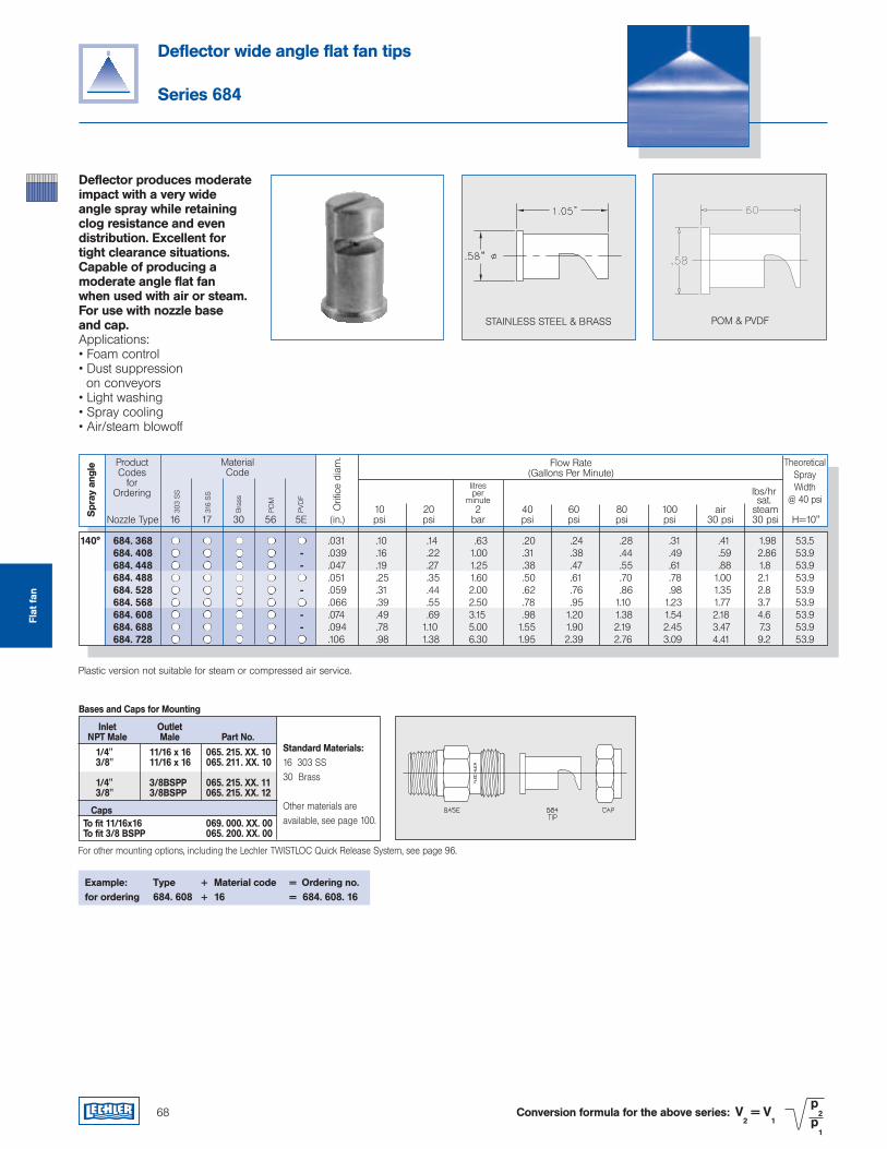
Deflector wide angle flat fan tips
Series 684
Deflector produces moderate impact with a very wide angle spray while retaining clog resistance and even distribution. Excellent for tight clearance situations. Capable of producing a moderate angle flat fan when used with air or steam. For use with nozzle base and cap.Applications:• Foam control• Dust suppression on conveyors• Light washing• Spray cooling• Air/steam blowoff
ProductCodes
for Ordering
Flow Rate(Gallons Per Minute)
TheoreticalSpray Width
@ 40 psi
MaterialCode
303
SS
316
SS
litresper
minute
Orifi
ce d
iam
.
Spr
ay a
ngle
Bra
ss
lbs/hrsat.
68 Conversion formula for the above series: V2 = V
1
p2
p1
10 20 2 40 60 80 100 air steam Nozzle Type 16 17 30 56 5E (in.) psi psi bar psi psi psi psi 30 psi 30 psi H=10"
POM
Plastic version not suitable for steam or compressed air service.
Example: Type + Material code = Ordering no.for ordering 684. 608 + 16 = 684. 608. 16
1/4" 11/16 x 16 065. 215. XX. 10 3/8" 11/16 x 16 065. 211. XX. 10
1/4" 3/8BSPP 065. 215. XX. 11 3/8" 3/8BSPP 065. 215. XX. 12
To fit 11/16x16 069. 000. XX. 00 To fit 3/8 BSPP 065. 200. XX. 00
Standard Materials:16 303 SS 30 Brass
Other materials are available, see page 100.
Inlet Outlet NPT Male Male Part No.
Bases and Caps for Mounting
Caps
For other mounting options, including the Lechler TWISTLOC Quick Release System, see page 96.
STAINLESS STEEL & BRASS POM & PVDF
140° 684. 368 .031 .10 .14 .63 .20 .24 .28 .31 .41 1.98 53.5 684. 408 - .039 .16 .22 1.00 .31 .38 .44 .49 .59 2.86 53.9 684. 448 - .047 .19 .27 1.25 .38 .47 .55 .61 .88 1.8 53.9 684. 488 .051 .25 .35 1.60 .50 .61 .70 .78 1.00 2.1 53.9 684. 528 - .059 .31 .44 2.00 .62 .76 .86 .98 1.35 2.8 53.9 684. 568 .066 .39 .55 2.50 .78 .95 1.10 1.23 1.77 3.7 53.9 684. 608 - .074 .49 .69 3.15 .98 1.20 1.38 1.54 2.18 4.6 53.9 684. 688 - .094 .78 1.10 5.00 1.55 1.90 2.19 2.45 3.47 7.3 53.9 684. 728 .106 .98 1.38 6.30 1.95 2.39 2.76 3.09 4.41 9.2 53.9
PVD
F
Flat
fan
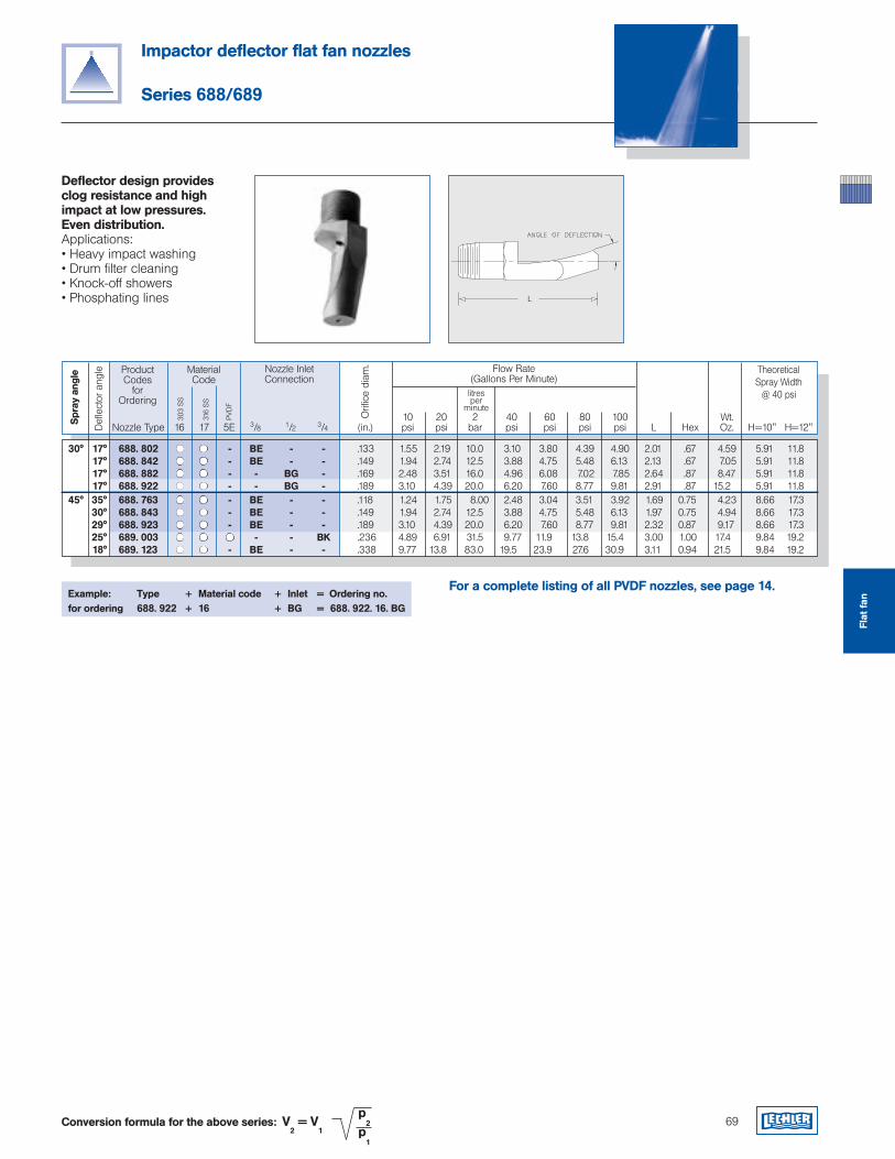
Impactor deflector flat fan nozzles
Series 688/689
Deflector design provides clog resistance and high impact at low pressures. Even distribution.Applications:• Heavy impact washing• Drum filter cleaning• Knock-off showers• Phosphating lines
69Conversion formula for the above series: V2 = V
1
p2
p1
ProductCodes
for Ordering
Flow Rate(Gallons Per Minute)
TheoreticalSpray Width
@ 40 psi
10 20 2 40 60 80 100 Wt. Nozzle Type 16 17 5E 3/8 1/2 3/4 (in.) psi psi bar psi psi psi psi L Hex Oz. H=10" H=12"
MaterialCode
303
SS
316
SS
litresper
minute
Nozzle Inlet Connection
Orifi
ce d
iam
.
Spr
ay a
ngle
PVD
F
Example: Type + Material code + Inlet = Ordering no.for ordering 688. 922 + 16 + BG = 688. 922. 16. BG
Defl
ecto
r an
gle
30° 17° 688. 802 - BE - - .133 1.55 2.19 10.0 3.10 3.80 4.39 4.90 2.01 .67 4.59 5.91 11.8 17° 688. 842 - BE - - .149 1.94 2.74 12.5 3.88 4.75 5.48 6.13 2.13 .67 7.05 5.91 11.8 17° 688. 882 - - BG - .169 2.48 3.51 16.0 4.96 6.08 7.02 7.85 2.64 .87 8.47 5.91 11.8 17° 688. 922 - - BG - .189 3.10 4.39 20.0 6.20 7.60 8.77 9.81 2.91 .87 15.2 5.91 11.8 45° 35° 688. 763 - BE - - .118 1.24 1.75 8.00 2.48 3.04 3.51 3.92 1.69 0.75 4.23 8.66 17.3 30° 688. 843 - BE - - .149 1.94 2.74 12.5 3.88 4.75 5.48 6.13 1.97 0.75 4.94 8.66 17.3 29° 688. 923 - BE - - .189 3.10 4.39 20.0 6.20 7.60 8.77 9.81 2.32 0.87 9.17 8.66 17.3 25° 689. 003 - - BK .236 4.89 6.91 31.5 9.77 11.9 13.8 15.4 3.00 1.00 17.4 9.84 19.2 18° 689. 123 - BE - - .338 9.77 13.8 83.0 19.5 23.9 27.6 30.9 3.11 0.94 21.5 9.84 19.2
For a complete listing of all PVDF nozzles, see page 14.
Flat
fan
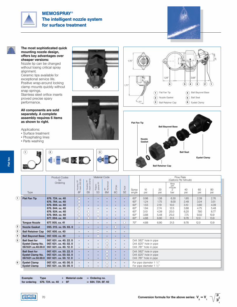
MEMOSPRAY®
The intelligent nozzle systemfor surface treatment
70 Conversion formula for the above series: V2 = V
1
p2
p1
The most sophisticated quick mounting nozzle design, offers key advantages over cheaper versions:Nozzle tip can be changed without losing critical spray alignment.Ceramic tips available for exceptional service life.Positive wrap-around locking clamp mounts quickly without snap springs.Stainless steel orifice inserts proved precise spary performance.
All components are sold separately. A complete assembly requires 6 items as shown to right.
Applications:• Surface treatment• Phosphating lines• Parts washing
Example: Type + Material code = Ordering no.for ordering 676. 724. xx. 40 + 8F = 684. 724. 8F. 40
Flat Fan Tip
NozzleGasket
Ball Retainer Cap
Ball Bayonet Base
Ball Seat
Eyelet Clamp
Product Codesfor
Ordering
Flow Rate(Gallons Per Minute)
Material Code
Hou
sing
: PP
Inse
rt: 3
03 S
S
litresper
minute
1 2 3
Hou
sing
: PP
Inse
rt: c
eram
ic
Poly
pro-
pyle
ne P
P
PP
Rei
nfor
ced
EPD
M
PVD
F
Spray 10 20 2 40 60 80 Type 8F E8 53 6M 6C 5E angle psi psi bar psi psi psi
1
2
3
4
5
6
1
2
3
Flat Fan Tip
Nozzle Gasket
Ball Retainer Cap
4
5
6
Ball Bayonet Base
Ball Seat
Eyelet Clamp
6 5 4 3 2 1
Flat Fan Tip 676. 724. xx. 40 - - - - - 60° 0.98 1.38 6.30 1.95 2.39 2.76 676. 764. xx. 40 - - - - - 60° 1.24 1.75 8.00 2.48 3.04 3.51 676. 804. xx. 40 - - - - - 60° 1.55 2.19 10.0 3.10 3.80 4.39 676. 844. xx. 40 - - - - - 60° 1.94 2.74 12.5 3.88 4.75 5.48 676. 924. xx. 40 - - - 60° 3.10 4.39 20.0 6.20 7.60 8.77 676. 964. xx. 40 - - - 60° 3.88 5.48 25.0 7.75 9.50 10.9 677. 004. xx. 40 - - - 60° 4.88 6.90 31.5 9.78 12.0 13.9
Tongue Nozzle 677. 005. xx. 41 - - - - - 70° 4.88 6.90 31.5 9.78 12.0 13.9
Nozzle Gasket 095. 015. xx. 05. 65. 0 - - - - -
Ball Retainer Cap 067. 600. xx. 40 - - - - -
Ball Bayonet Base 067. 630. xx. 40 - - - - -
Ball Seat for 067. 631. xx. 40. 22. 0 - - - - - Drill .562" hole in pipe Eyelet Clamp No. 067. 631. xx. 40. 02. 0 - - - - - Drill .625" hole in pipe 067.631.xx.40.00.0 067. 631. xx. 40. 12. 0 - - - - - Drill .781" hole in pipe
Ball Seat for 067. 631. xx. 50. 22. 0 - - - - - Drill .562" hole in pipe Eyelet Clamp No. 067. 631. xx. 50. 02. 0 - - - - - Drill .625" hole in pipe 067.631.xx.50.00.0 067. 631. xx. 50. 12. 0 - - - - - Drill .781" hole in pipe
Eyelet Clamp 067. 631. xx. 40. 00. 0 - - - - - For pipe diameter 1 1/4" Eyelet Clamp 067. 631. xx. 50. 00. 0 - - - - - For pipe diameter 1 1/2"
1.75"
1.71"
1.28" 3.68"
Flat
fan
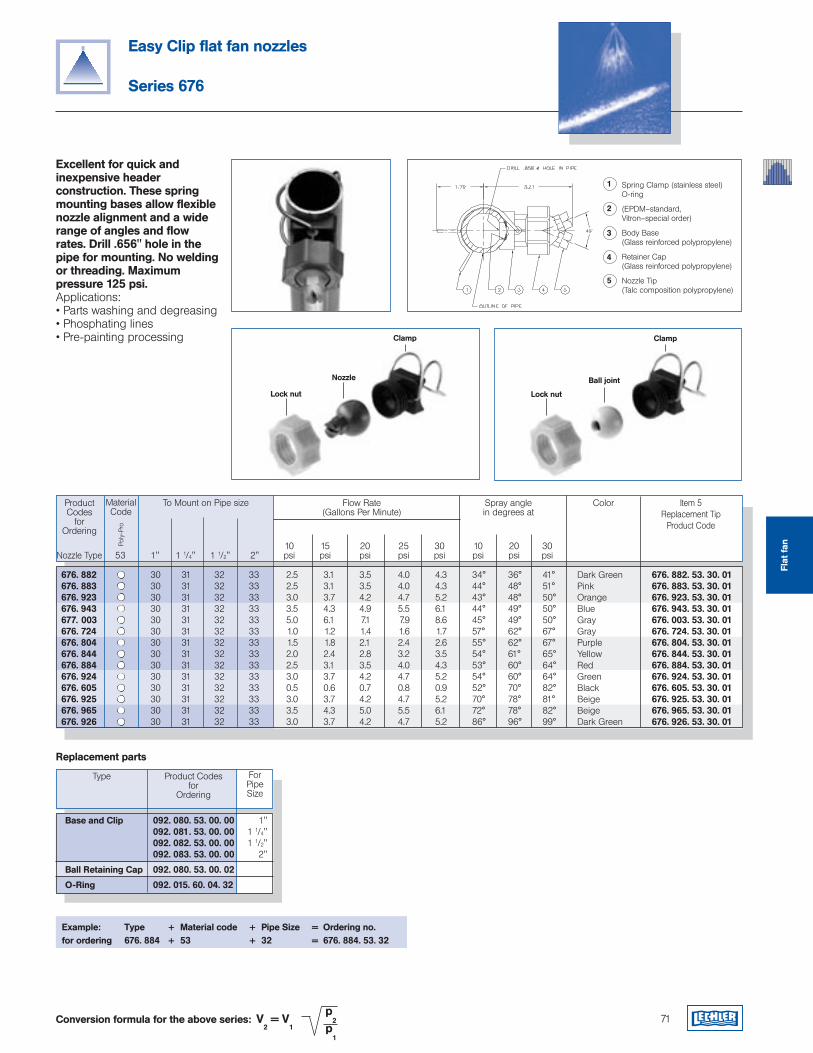
Lock nut
Ball joint
Clamp
Easy Clip flat fan nozzles
Series 676
Excellent for quick and inexpensive header construction. These spring mounting bases allow flexible nozzle alignment and a wide range of angles and flow rates. Drill .656" hole in the pipe for mounting. No welding or threading. Maximum pressure 125 psi.Applications:• Parts washing and degreasing• Phosphating lines• Pre-painting processing
71Conversion formula for the above series: V2 = V
1
p2
p1
1
2
3
Spring Clamp (stainless steel)O-ring
(EPDM–standard, Vitron–special order)
Body Base(Glass reinforced polypropylene)
Retainer Cap(Glass reinforced polypropylene)
Nozzle Tip(Talc composition polypropylene)
4
5
ProductCodes
for Ordering
Flow Rate(Gallons Per Minute)
Item 5Replacement Tip
Product Code
To Mount on Pipe size
Poly
-Pro
10 15 20 25 30 10 20 30 Nozzle Type 53 1" 1 1/4" 1 1/2" 2" psi psi psi psi psi psi psi psi
MaterialCode
Spray anglein degrees at
Color
Lock nut
Nozzle
Clamp
Product Codesfor
Ordering
ForPipeSize
Type
Replacement parts
Base and Clip 092. 080. 53. 00. 00 1" 092. 081. 53. 00. 00 1 1/4" 092. 082. 53. 00. 00 1 1/2" 092. 083. 53. 00. 00 2"
Ball Retaining Cap 092. 080. 53. 00. 02
O-Ring 092. 015. 60. 04. 32
Example: Type + Material code + Pipe Size = Ordering no.for ordering 676. 884 + 53 + 32 = 676. 884. 53. 32
676. 882 30 31 32 33 2.5 3.1 3.5 4.0 4.3 34° 36° 41° Dark Green 676. 882. 53. 30. 01 676. 883 30 31 32 33 2.5 3.1 3.5 4.0 4.3 44° 48° 51° Pink 676. 883. 53. 30. 01 676. 923 30 31 32 33 3.0 3.7 4.2 4.7 5.2 43° 48° 50° Orange 676. 923. 53. 30. 01 676. 943 30 31 32 33 3.5 4.3 4.9 5.5 6.1 44° 49° 50° Blue 676. 943. 53. 30. 01 677. 003 30 31 32 33 5.0 6.1 7.1 7.9 8.6 45° 49° 50° Gray 676. 003. 53. 30. 01 676. 724 30 31 32 33 1.0 1.2 1.4 1.6 1.7 57° 62° 67° Gray 676. 724. 53. 30. 01 676. 804 30 31 32 33 1.5 1.8 2.1 2.4 2.6 55° 62° 67° Purple 676. 804. 53. 30. 01 676. 844 30 31 32 33 2.0 2.4 2.8 3.2 3.5 54° 61° 65° Yellow 676. 844. 53. 30. 01 676. 884 30 31 32 33 2.5 3.1 3.5 4.0 4.3 53° 60° 64° Red 676. 884. 53. 30. 01 676. 924 30 31 32 33 3.0 3.7 4.2 4.7 5.2 54° 60° 64° Green 676. 924. 53. 30. 01 676. 605 30 31 32 33 0.5 0.6 0.7 0.8 0.9 52° 70° 82° Black 676. 605. 53. 30. 01 676. 925 30 31 32 33 3.0 3.7 4.2 4.7 5.2 70° 78° 81° Beige 676. 925. 53. 30. 01 676. 965 30 31 32 33 3.5 4.3 5.0 5.5 6.1 72° 78° 82° Beige 676. 965. 53. 30. 01 676. 926 30 31 32 33 3.0 3.7 4.2 4.7 5.2 86° 96° 99° Dark Green 676. 926. 53. 30. 01
Flat
fan
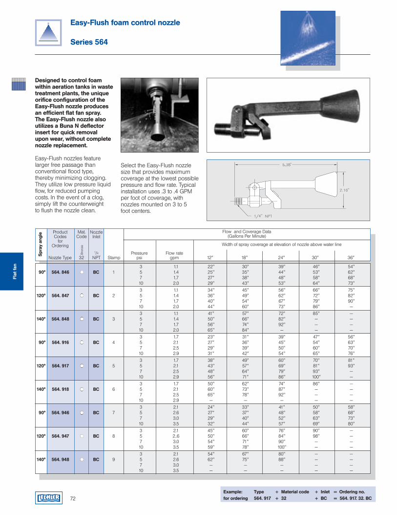
Easy-Flush foam control nozzle
Series 564
72
Designed to control foam within aeration tanks in waste treatment plants, the unique orifice configuration of the Easy-Flush nozzle produces an efficient flat fan spray. The Easy-Flush nozzle also utilizes a Buna N deflector insert for quick removal upon wear, without complete nozzle replacement.
Easy-Flush nozzles feature larger free passage than conventional flood type, thereby minimizing clogging. They utilize low pressure liquid flow, for reduced pumping costs. In the event of a clog, simply lift the counterweight to flush the nozzle clean.
Select the Easy-Flush nozzle size that provides maximum coverage at the lowest possible pressure and flow rate. Typical installation uses .3 to .4 GPM per foot of coverage, with nozzles mounted on 3 to 5 foot centers.
ProductCodes
for Ordering
Flow and Coverage Data(Gallons Per Minute)
1/4 Pressure Flow rate Nozzle Type 32 NPT Stamp psi gpm 12" 18" 24" 30" 36"
Mat.Code
Bro
nze Width of spray coverage at elevation of nozzle above water line
Spr
ay a
ngle
NozzleInlet
Example: Type + Material code + Inlet = Ordering no.for ordering 564. 917 + 32 + BC = 564. 917. 32. BC
3 1.1 22" 30" 39" 46" 54" 90° 564. 846 BC 1 5 1.4 25" 35" 44" 53" 62" 7 1.7 27" 38" 48" 58" 68" 10 2.0 29" 43" 53" 64" 73"
3 1.1 34" 45" 56" 66" 75" 120° 564. 847 BC 2 5 1.4 36" 49" 62" 72" 82" 7 1.7 40" 54" 67" 79" 90" 10 2.0 44" 60" 73" 86" —
3 1.1 41" 57" 72" 85" — 140° 564. 848 BC 3 5 1.4 50" 66" 82" — — 7 1.7 56" 74" 92" — — 10 2.0 65" 84" — — —
3 1.7 23" 31" 39" 47" 56" 90° 564. 916 BC 4 5 2.1 27" 36" 45" 54" 63" 7 2.5 29" 39" 50" 60" 70" 10 2.9 31" 42" 54" 65" 76"
3 1.7 38" 49" 60" 70" 81" 120° 564. 917 BC 5 5 2.1 43" 57" 69" 81" 93" 7 2.5 48" 64" 79" 93" — 10 2.9 56" 71" 86" 100" —
3 1.7 50" 62" 74" 86" — 140° 564. 918 BC 6 5 2.1 60" 73" 87" — — 7 2.5 65" 78" 92" — — 10 2.9 — — — — —
3 2.1 24" 33" 41" 50" 58" 90° 564. 946 BC 7 5 2.6 27" 37" 48" 58" 68" 7 3.0 29" 40" 52" 63" 73" 10 3.5 32" 44" 57" 69" 80"
3 2.1 45" 60" 76" 90" — 120° 564. 947 BC 8 5 2..6 50" 66" 84" 98" — 7 3.0 54" 71" 90" — — 10 3.5 59" 78" 100" — —
3 2.1 54" 67" 80" — — 140° 564. 948 BC 9 5 2.6 62" 75" 88" — — 7 3.0 — — — — — 10 3.5 — — — — —
Flat
fan

Air curtainsBlowing off and outCleaningCoolingDryingReheatingTransportingand many others...
Air nozzles
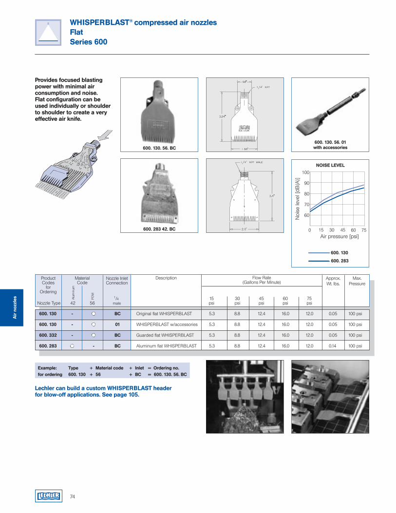
74
WHISPERBLAST® compressed air nozzles FlatSeries 600
Provides focused blasting power with minimal air consumption and noise. Flat configuration can be used individually or shoulder to shoulder to create a very effective air knife.
Example: Type + Material code + Inlet = Ordering no.for ordering 600. 130 + 56 + BC = 600. 130. 56. BC
ProductCodes
for Ordering
Flow Rate(Gallons Per Minute)
Max.Pressure
MaterialCode
Nozzle Inlet Connection
1/4 15 30 45 60 75 Nozzle Type 42 56 male psi psi psi psi psi
Approx.Wt. lbs.
Description
Alu
min
um
POM
600. 130. 56. BC
600. 283 42. BC
600. 130. 56. 01with accessories
Lechler can build a custom WHISPERBLAST header for blow-off applications. See page 105.
600. 130 - BC Original flat WHISPERBLAST 5.3 8.8 12.4 16.0 12.0 0.05 100 psi
600. 130 - 01 WHISPERBLAST w/accessories 5.3 8.8 12.4 16.0 12.0 0.05 100 psi
600. 332 - BC Guarded flat WHISPERBLAST 5.3 8.8 12.4 16.0 12.0 0.05 100 psi
600. 283 - BC Aluminum flat WHISPERBLAST 5.3 8.8 12.4 16.0 12.0 0.14 100 psi
0
100
90
80
70
60
Air pressure [psi]
Noi
se le
vel [
dB(A
)]
15 30 45 60 75
600. 130
600. 283
NOISE LEVEL
Air
noz
zles
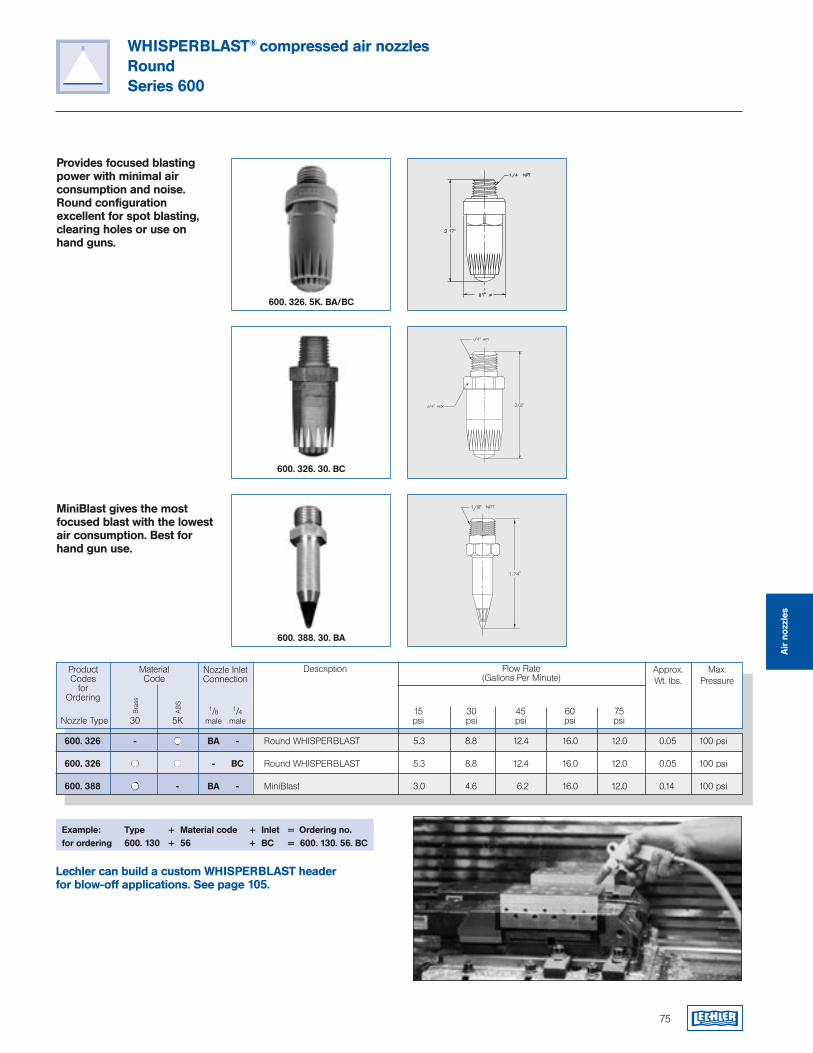
75
Provides focused blasting power with minimal air consumption and noise. Round configuration excellent for spot blasting, clearing holes or use on hand guns.
MiniBlast gives the most focused blast with the lowest air consumption. Best for hand gun use.
WHISPERBLAST® compressed air nozzles RoundSeries 600
Example: Type + Material code + Inlet = Ordering no.for ordering 600. 130 + 56 + BC = 600. 130. 56. BC
ProductCodes
for Ordering
Flow Rate(Gallons Per Minute)
Max.Pressure
MaterialCode
Bra
ss
Nozzle Inlet Connection
1/8 1/4 15 30 45 60 75 Nozzle Type 30 5K male male psi psi psi psi psi
Approx.Wt. lbs.
Description
AB
S
600. 326 - BA - Round WHISPERBLAST 5.3 8.8 12.4 16.0 12.0 0.05 100 psi
600. 326 - BC Round WHISPERBLAST 5.3 8.8 12.4 16.0 12.0 0.05 100 psi
600. 388 - BA - MiniBlast 3.0 4.6 6.2 16.0 12.0 0.14 100 psi
600. 326. 5K. BA/BC
600. 326. 30. BC
600. 388. 30. BA
Lechler can build a custom WHISPERBLAST header for blow-off applications. See page 105.
Air
noz
zles
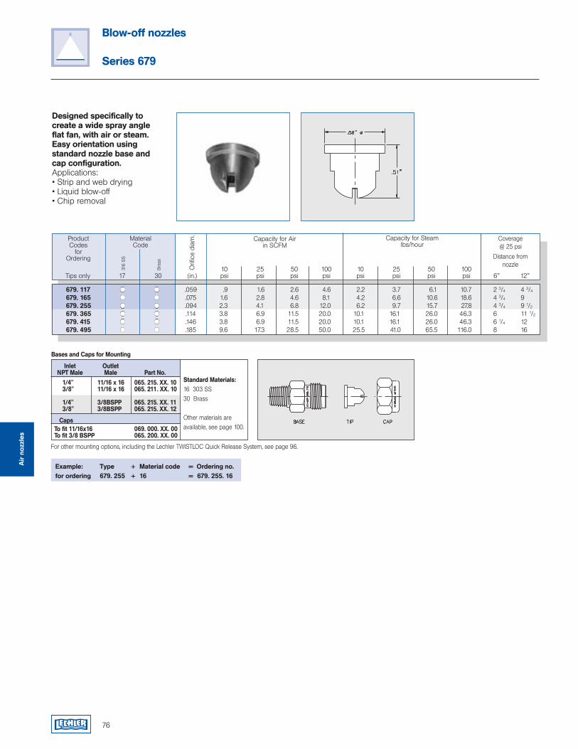
Designed specifically to create a wide spray angle flat fan, with air or steam. Easy orientation using standard nozzle base and cap configuration.Applications:• Strip and web drying• Liquid blow-off• Chip removal
1/4" 11/16 x 16 065. 215. XX. 10 3/8" 11/16 x 16 065. 211. XX. 10
1/4" 3/8BSPP 065. 215. XX. 11 3/8" 3/8BSPP 065. 215. XX. 12
To fit 11/16x16 069. 000. XX. 00 To fit 3/8 BSPP 065. 200. XX. 00
Standard Materials:16 303 SS 30 Brass
Other materials are available, see page 100.
Inlet Outlet NPT Male Male Part No.
Bases and Caps for Mounting
Caps
For other mounting options, including the Lechler TWISTLOC Quick Release System, see page 96.
ProductCodes
for Ordering
Capacity for Airin SCFM
Coverage@ 25 psi
Distance fromnozzle
MaterialCode
316
SS
Orifi
ce d
iam
.
Bra
ss
10 25 50 100 10 25 50 100 Tips only 17 30 (in.) psi psi psi psi psi psi psi psi 6" 12"
Capacity for Steamlbs/hour
679. 117 .059 .9 1.6 2.6 4.6 2.2 3.7 6.1 10.7 2 3/4 4 3/4
679. 165 .075 1.6 2.8 4.6 8.1 4.2 6.6 10.6 18.6 4 3/4 9 679. 255 .094 2.3 4.1 6.8 12.0 6.2 9.7 15.7 27.8 4 3/4 9 1/2
679. 365 .114 3.8 6.9 11.5 20.0 10.1 16.1 26.0 46.3 6 11 1/2
679. 415 .146 3.8 6.9 11.5 20.0 10.1 16.1 26.0 46.3 6 1/4 12 679. 495 .185 9.6 17.3 28.5 50.0 25.5 41.0 65.5 116.0 8 16
Example: Type + Material code = Ordering no.for ordering 679. 255 + 16 = 679. 255. 16
Air
noz
zles
76
Blow-off nozzles
Series 679

Beverage industryBioengineeringChemical industryCosmetic industryFood industryPharmaceutical industryTank buildingand many others...
Tank cleaning nozzles
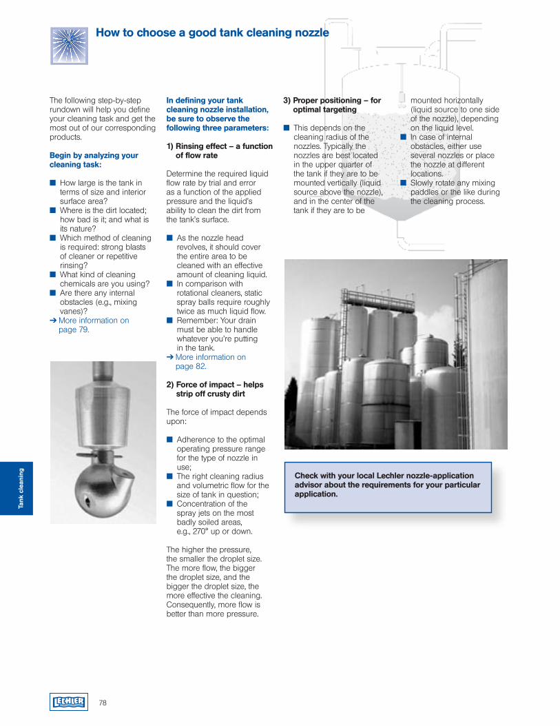
78
The following step-by-step rundown will help you define your cleaning task and get the most out of our corresponding products.
Begin by analyzing your cleaning task:
How large is the tank in terms of size and interior surface area?
Where is the dirt located; how bad is it; and what is its nature?
Which method of cleaning is required: strong blasts of cleaner or repetitive rinsing?
What kind of cleaning chemicals are you using?
Are there any internal obstacles (e.g., mixing vanes)?
More information on page 79.
In defining your tank cleaning nozzle installation, be sure to observe the following three parameters:
1) Rinsing effect – a function of flow rate
Determine the required liquid flow rate by trial and error as a function of the applied pressure and the liquid’s ability to clean the dirt from the tank’s surface.
As the nozzle head revolves, it should cover the entire area to be cleaned with an effective amount of cleaning liquid.
In comparison with rotational cleaners, static spray balls require roughly twice as much liquid flow.
Remember: Your drain must be able to handle whatever you’re putting
in the tank. More information on
page 82. 2) Force of impact – helps
strip off crusty dirt
The force of impact depends upon:
Adherence to the optimal operating pressure range for the type of nozzle in use;
The right cleaning radius and volumetric flow for the size of tank in question;
Concentration of the spray jets on the most
badly soiled areas, e.g., 270° up or down.
The higher the pressure, the smaller the droplet size. The more flow, the bigger the droplet size, and the bigger the droplet size, the more effective the cleaning. Consequently, more flow is better than more pressure.
mounted horizontally (liquid source to one side
of the nozzle), depending on the liquid level.
In case of internal obstacles, either use several nozzles or place the nozzle at different locations.
Slowly rotate any mixing paddles or the like during the cleaning process.
3) Proper positioning – for optimal targeting
This depends on the cleaning radius of the nozzles. Typically the nozzles are best located in the upper quarter of the tank if they are to be mounted vertically (liquid source above the nozzle), and in the center of the tank if they are to be
How to choose a good tank cleaning nozzle
Check with your local Lechler nozzle-application advisor about the requirements for your particular application.
Tank
cle
anin
g
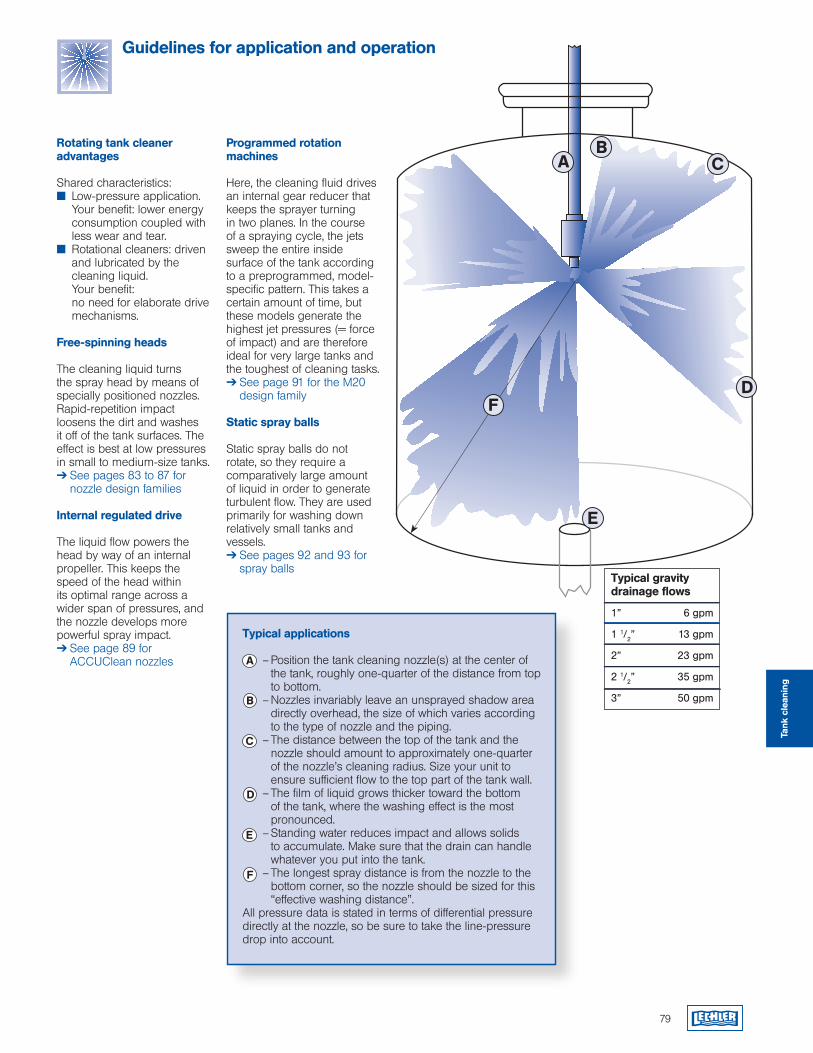
Rotating tank cleaner advantages
Shared characteristics: Low-pressure application.
Your benefit: lower energy consumption coupled with less wear and tear.
Rotational cleaners: driven and lubricated by the cleaning liquid.
Your benefit: no need for elaborate drive mechanisms.
Free-spinning heads
The cleaning liquid turns the spray head by means of specially positioned nozzles. Rapid-repetition impact loosens the dirt and washes it off of the tank surfaces. The effect is best at low pressures in small to medium-size tanks. See pages 83 to 87 for
nozzle design families
Internal regulated drive
The liquid flow powers the head by way of an internal propeller. This keeps the speed of the head within its optimal range across a wider span of pressures, and the nozzle develops more powerful spray impact. See page 89 for
ACCUClean nozzles
Programmed rotation machines
Here, the cleaning fluid drives an internal gear reducer that keeps the sprayer turning in two planes. In the course of a spraying cycle, the jets sweep the entire inside surface of the tank according to a preprogrammed, model-specific pattern. This takes a certain amount of time, but these models generate the highest jet pressures (= force of impact) and are therefore ideal for very large tanks and the toughest of cleaning tasks. See page 91 for the M20
design family
Static spray balls
Static spray balls do not rotate, so they require a comparatively large amount of liquid in order to generate turbulent flow. They are used primarily for washing down relatively small tanks and vessels. See pages 92 and 93 for
spray ballsTypical gravity drainage flows
1” 6 gpm
1 1/2” 13 gpm
2” 23 gpm
2 1/2” 35 gpm
3” 50 gpm
79
Guidelines for application and operation
D
E
CA
F
B
Typical applications
– Position the tank cleaning nozzle(s) at the center of the tank, roughly one-quarter of the distance from top to bottom.
– Nozzles invariably leave an unsprayed shadow area directly overhead, the size of which varies according to the type of nozzle and the piping.
– The distance between the top of the tank and the nozzle should amount to approximately one-quarter of the nozzle’s cleaning radius. Size your unit to ensure sufficient flow to the top part of the tank wall.
– The film of liquid grows thicker toward the bottom of the tank, where the washing effect is the most pronounced.
– Standing water reduces impact and allows solids to accumulate. Make sure that the drain can handle whatever you put into the tank.
– The longest spray distance is from the nozzle to the bottom corner, so the nozzle should be sized for this “effective washing distance”.
All pressure data is stated in terms of differential pressure directly at the nozzle, so be sure to take the line-pressure drop into account.
F
D
E
C
A
B
Tank
cle
anin
g
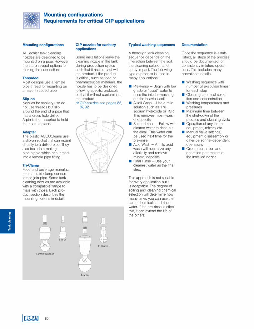
Typical washing sequences
A thorough tank cleaningsequence depends on theinteraction between the soil,the cleaning solution andspray impact. The following type of process is used in many applications:
Pre-Rinse — Begin with low grade or “used” water to rinse the interior, washing out the heaviest soil.
Alkali Wash — Use a mild solution such as 1 % sodium hydroxide or TSP. This removes most types of deposits.
Second rinse — Follow with cleaner water to rinse out the alkali. This water can be used next time for the pre-rinse.
Acid Wash — A mild acid wash will neutralize any alkalinity and remove mineral deposits
Final Rinse — Use your cleanest water as the final step.
This approach is not suitablefor every application but itis adaptable. The degree ofsoiling and cleaning chemicalselection will determine howmany times you can use thesame chemicals and rinsewater. If the pre-rinse is effec-tive, it can extend the life of the others.
Documentation
Once the sequence is estab-lished, all steps of the process should be documented for consistency in future opera-tions. This includes many operational details:
Washing sequence with number of execution times for each step
Cleaning chemical selec- tion and concentration
Washing temperatures and pressures
Maximum time between the shut-down of the process and cleaning cycle
Operation of any internal equipment, mixers, etc.
Manual valve settings, equipment disassembly or other personnel-dependent operations
Order information and operation parameters of the installed nozzle
CIP-nozzles for sanitary applications
Some installations leave thecleaning nozzle in the tankduring production cyclessuch that it has contact withthe product. If the productis critical, such as food orpharmaceutical materials, thenozzle has to be designedfollowing specific protocols so that it will not contaminate the product. CIP-nozzles see pages 85,
87, 92
Mounting configurations
All Lechler tank cleaningnozzles are designed to bemounted on a pipe. Howeverthere are several options formaking the connection:
ThreadedMost designs use a femalepipe thread for mounting on a male threaded pipe.
Slip-onNozzles for sanitary use do not use threads but slip around the end of a pipe that has a cross hole drilled.A pin is then inserted to holdthe head in place.
AdapterThe plastic ACCUCleans use a slip-on socket that can mount directly to a drilled pipe. They also include a matingpipe nipple which can thread into a female pipe fitting.
Tri-ClampFood and beverage manufac-turers use tri-clamp connec-tors to join pipe. Some tank cleaning nozzles are available with a compatible flange to mate with those. Each pro-duct section describes the mounting options in detail.
80
Female threaded
Slip-on
Adapter
Tri-Clamp
Mounting configurations Requirements for critical CIP applications
Tank
cle
anin
g
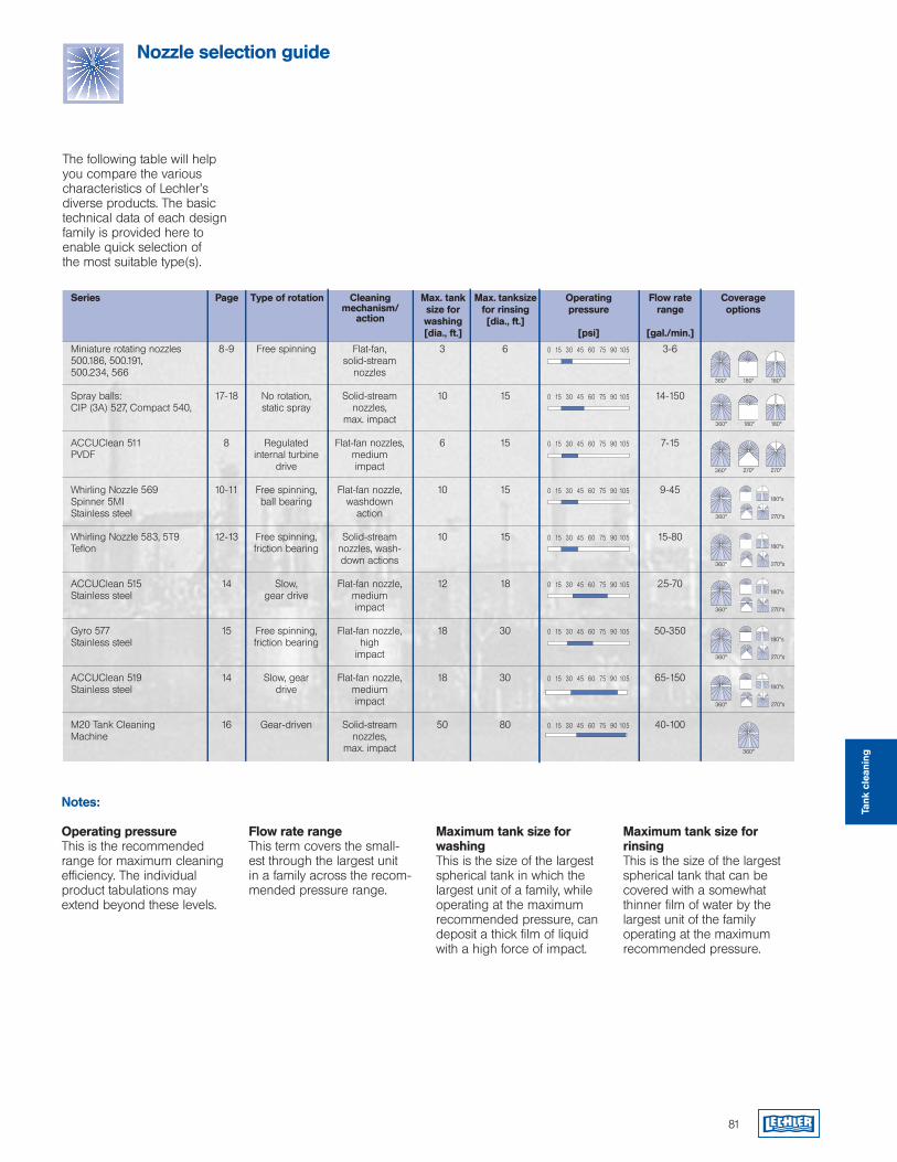
81
Nozzle selection guide
Miniature rotating nozzles 8-9 Free spinning Flat-fan, 3 6 0 15 30 45 60 75 90 105 3-6 500.186, 500.191, solid-stream500.234, 566 nozzles
Spray balls: 17-18 No rotation, Solid-stream 10 15 0 15 30 45 60 75 90 105 14-150 CIP (3A) 527, Compact 540, static spray nozzles, max. impact
ACCUClean 511 8 Regulated Flat-fan nozzles, 6 15 0 15 30 45 60 75 90 105 7-15PVDF internal turbine medium drive impact
Whirling Nozzle 569 10-11 Free spinning, Flat-fan nozzle, 10 15 0 15 30 45 60 75 90 105 9-45Spinner 5MI ball bearing washdownStainless steel action
Whirling Nozzle 583, 5T9 12-13 Free spinning, Solid-stream 10 15 0 15 30 45 60 75 90 105 15-80Teflon friction bearing nozzles, wash- down actions
ACCUClean 515 14 Slow, Flat-fan nozzle, 12 18 0 15 30 45 60 75 90 105 25-70Stainless steel gear drive medium impact
Gyro 577 15 Free spinning, Flat-fan nozzle, 18 30 0 15 30 45 60 75 90 105 50-350Stainless steel friction bearing high impact
ACCUClean 519 14 Slow, gear Flat-fan nozzle, 18 30 0 15 30 45 60 75 90 105 65-150Stainless steel drive medium impact
M20 Tank Cleaning 16 Gear-driven Solid-stream 50 80 0 15 30 45 60 75 90 105 40-100Machine nozzles, max. impact
The following table will help you compare the various characteristics of Lechler’s diverse products. The basic technical data of each design family is provided here to enable quick selection of the most suitable type(s).
Series Page Type of rotation Cleaning mechanism/
action
Max. tank size for washing[dia., ft.]
Max. tanksize for rinsing[dia., ft.]
Operatingpressure
[psi]
Flow rate range
[gal./min.]
Coverageoptions
Notes:
Operating pressureThis is the recommended range for maximum cleaning efficiency. The individual product tabulations may extend beyond these levels.
Flow rate rangeThis term covers the small-est through the largest unit in a family across the recom-mended pressure range.
Maximum tank size for washingThis is the size of the largest spherical tank in which the largest unit of a family, while operating at the maximum recommended pressure, can deposit a thick film of liquid with a high force of impact.
Maximum tank size for rinsingThis is the size of the largest spherical tank that can be covered with a somewhat thinner film of water by the largest unit of the family operating at the maximum recommended pressure.
360° 180° 180°
180°360° 180°
270°360° 270°
180°s
270°s360°
180°s
270°s360°
180°s
270°s360°
180°s
270°s360°
180°s
270°s360°
360°
Tank
cle
anin
g
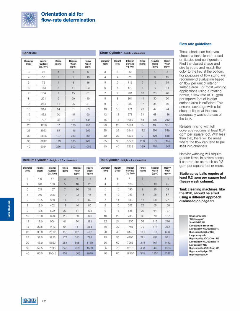
Flow rate guidelines
These charts can help you choose a tank cleaner based on its size and configuration. Find the closest shape and size to yours and match the color to the key at the bottom. For purposes of flow sizing, we recommend evaluation based on flow per unit of interior surface area. For most washing applications using a rotating nozzle, a flow rate of 0.1 gpm per square foot of interior surface area is sufficient. This ensures coverage with a full sheet of liquid at the least adequately washed areas of the tank.
Reliable rinsing with full coverage requires at least 0.04 gpm per square foot. With less than that, there will be areas where the flow can tend to pull itself into channels.
Heavier washing will require greater flows. In severe cases, it can require as much as 0.2 gpm per square foot or more.
Static spray balls require at least 0.2 gpm per square foot (heavy wash column).
Tank cleaning machines, like the M20, should be sized using a different approach discussed on page 91.
Small spray balls“Mini designs”Small PVDF 511Low capacity 569 or 583 Low capacity ACCUClean 515High capacity 569 or 583Large spray ballsHigh capacity ACCUClean 515Low capacity ACCUClean 519Low capacity M20High capacity ACCUClean 519High capacity Gyro 577High capacity M20
Orientation aid for flow-rate determination
Medium Cylinder (height = 1.5 x diameter)
Spherical Short Cylinder (height = diameter)
Tall Cylinder (height = 2 x diameter)
Tank
cle
anin
g
Diameter(feet)
Height(feet)
Interior Surface(sq. feet)
Rinse(gpm)
Regular Wash(gpm)
Heavy Wash(gpm)
3 6 71 3 7 14
4 8 126 6 13 25
5 10 196 9 20 39
6 12 283 13 28 57
7 14 385 17 38 77
8 16 502 23 50 100
9 18 636 29 64 127
10 20 785 35 79 157
12 24 1130 51 113 226
15 30 1766 79 177 353
20 40 3140 141 314 628
25 50 4906 221 491 981
30 60 7065 318 707 1413
35 70 9616 433 962 1923
40 80 12560 565 1256 2512
Diameter(feet)
Height(feet)
Interior Surface(sq. feet)
Rinse(gpm)
Regular Wash(gpm)
Heavy Wash(gpm)
3 4.5 57 3 6 11
4 6.0 100 5 10 20
5 7.5 157 7 16 31
6 9.0 226 10 23 45
7 10.5 308 14 31 62
8 12.0 402 18 40 80
9 13.5 509 23 51 102
10 15.0 628 28 63 126
12 18.0 904 41 90 181
15 22.5 1413 64 141 283
20 30.0 2512 113 251 502
25 37.5 3925 177 393 785
30 45.0 5652 254 565 1130
35 52.5 7693 346 769 1539
40 60.0 10048 452 1005 2010
Diameter(feet)
Height(feet)
Interior Surface(sq. feet)
Rinse(gpm)
Regular Wash(gpm)
Heavy Wash(gpm)
3 3 42 2 4 8
4 4 75 3 8 15
5 5 118 5 12 24
6 6 170 8 17 34
7 7 231 10 23 46
8 8 301 14 30 60
9 9 382 17 38 76
10 10 471 21 47 94
12 12 678 31 68 136
15 15 1060 48 106 212
20 20 1884 85 188 377
25 25 2944 132 294 589
30 30 4239 191 424 848
35 35 5770 260 577 1154
40 40 7536 339 754 1507
Diameter(feet)
Interior Surface (sq. feet)
Rinse(gpm)
Regular Wash(gpm)
Heavy Wash(gpm)
3 28 1 3 6
4 50 2 5 10
5 79 4 8 16
6 113 5 11 23
7 154 7 15 31
8 201 9 20 40
9 254 11 25 51
10 314 14 31 63
12 452 20 45 90
15 707 32 71 141
20 1256 57 126 251
25 1963 88 196 393
30 2826 127 283 565
35 3847 173 385 769
40 5024 226 502 1005
82
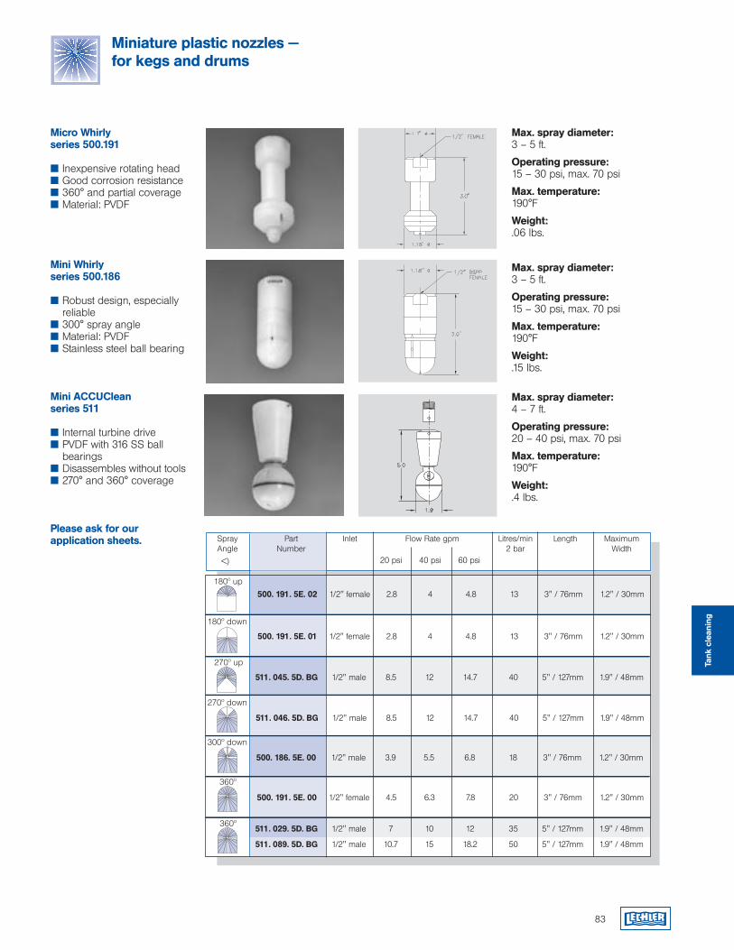
Micro Whirly series 500.191
Inexpensive rotating head Good corrosion resistance 360° and partial coverage Material: PVDF
Mini Whirlyseries 500.186
Robust design, especially reliable
300° spray angle Material: PVDF Stainless steel ball bearing
Mini ACCUCleanseries 511
Internal turbine drive PVDF with 316 SS ball
bearings Disassembles without tools 270° and 360° coverage
Please ask for our application sheets.
Max. spray diameter:3 – 5 ft.
Operating pressure:15 – 30 psi, max. 70 psi
Max. temperature:190°F
Weight:.06 lbs.
Max. spray diameter:3 – 5 ft.
Operating pressure:15 – 30 psi, max. 70 psi
Max. temperature:190°F
Weight:.15 lbs.
Max. spray diameter:4 – 7 ft.
Operating pressure:20 – 40 psi, max. 70 psi
Max. temperature:190°F
Weight:.4 lbs.
83
Miniature plastic nozzles — for kegs and drums
511. 045. 5D. BG 1/2" male 8.5 12 14.7 40 5" / 127mm 1.9" / 48mm
180º up
500. 191. 5E. 01 1/2" female 2.8 4 4.8 13 3" / 76mm 1.2" / 30mm
500. 191. 5E. 02 1/2" female 2.8 4 4.8 13 3" / 76mm 1.2" / 30mm
Flow Rate gpm
<)
InletPartNumber
SprayAngle
Litres/min 2 bar
Length MaximumWidth
20 psi 40 psi 60 psi
270º up
180º down
360º
270º down
360º
500. 191. 5E. 00 1/2" female 4.5 6.3 7.8 20 3" / 76mm 1.2" / 30mm
511. 046. 5D. BG 1/2" male 8.5 12 14.7 40 5" / 127mm 1.9" / 48mm
511. 029. 5D. BG 1/2" male 7 10 12 35 5" / 127mm 1.9" / 48mm
511. 089. 5D. BG 1/2" male 10.7 15 18.2 50 5" / 127mm 1.9" / 48mm
300º down
500. 186. 5E. 00 1/2" male 3.9 5.5 6.8 18 3" / 76mm 1.2" / 30mm
Tank
cle
anin
g
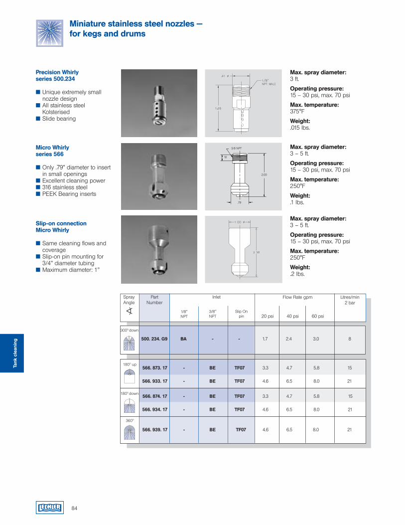
84
Miniature stainless steel nozzles — for kegs and drums
Max. spray diameter:3 ft.
Operating pressure:15 – 30 psi, max. 70 psi
Max. temperature:375°F
Weight:.015 lbs.
Max. spray diameter:3 – 5 ft.
Operating pressure:15 – 30 psi, max. 70 psi
Max. temperature:250°F
Weight:.1 lbs.
Max. spray diameter:3 – 5 ft.
Operating pressure:15 – 30 psi, max. 70 psi
Max. temperature:250°F
Weight:.2 lbs.
Precision Whirlyseries 500.234
Unique extremely small nozzle design
All stainless steel Kolsterised
Slide bearing
Micro Whirlyseries 566
Only .79” diameter to insert in small openings
Excellent cleaning power 316 stainless steel PEEK Bearing inserts
Slip-on connectionMicro Whirly
Same cleaning flows and coverage
Slip-on pin mounting for 3/4” diameter tubing
Maximum diameter: 1”
3/8 NPT
2.00
10
180º up
Flow Rate gpm
<) 1/8" NPT
PartNumber
SprayAngle
Litres/min 2 bar
20 psi 40 psi 60 psi 3/8" NPT
Inlet
180º down
Slip On pin
360º
300º down
.79
Tank
cle
anin
g
566. 939. 17 - BE TF07 4.6 6.5 8.0 21
500. 234. G9 BA - - 1.7 2.4 3.0 8
566. 873. 17 - BE TF07 3.3 4.7 5.8 15 566. 933. 17 - BE TF07 4.6 6.5 8.0 21
566. 874. 17 - BE TF07 3.3 4.7 5.8 15 566. 934. 17 - BE TF07 4.6 6.5 8.0 21
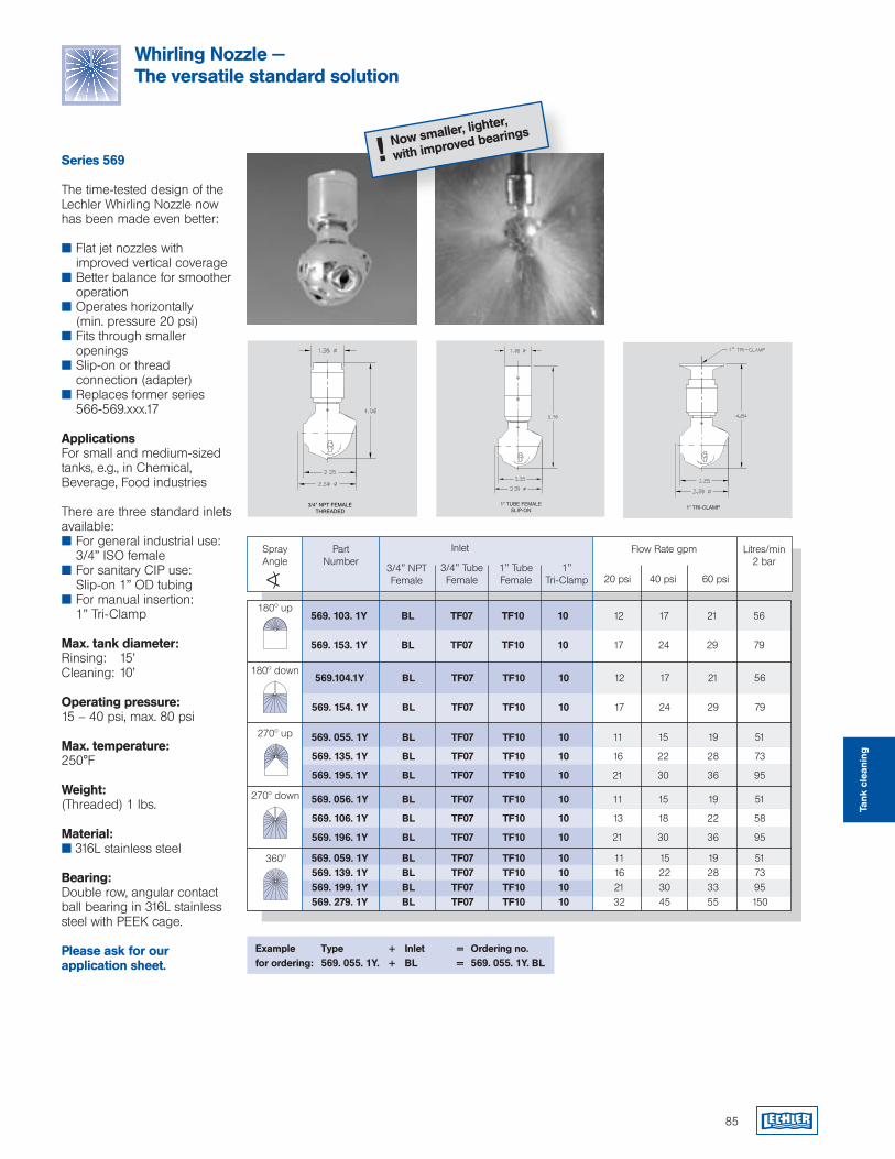
85
Whirling Nozzle — The versatile standard solution
Now smaller, lighter,
with improved bearings
!
Example Type + Inlet = Ordering no.for ordering: 569. 055. 1Y. + BL = 569. 055. 1Y. BL
270º down
Series 569
The time-tested design of the Lechler Whirling Nozzle now has been made even better: Flat jet nozzles with
improved vertical coverage Better balance for smoother
operation Operates horizontally
(min. pressure 20 psi) Fits through smaller
openings Slip-on or thread
connection (adapter) Replaces former series
566-569.xxx.17
ApplicationsFor small and medium-sized tanks, e.g., in Chemical, Beverage, Food industries
There are three standard inlets available: For general industrial use:
3/4” ISO female For sanitary CIP use:
Slip-on 1” OD tubing For manual insertion:
1” Tri-Clamp
Max. tank diameter:Rinsing: 15’Cleaning: 10’
Operating pressure:15 – 40 psi, max. 80 psi
Max. temperature:250°F
Weight:(Threaded) 1 lbs.
Material: 316L stainless steel
Bearing:Double row, angular contact ball bearing in 316L stainless steel with PEEK cage.
Please ask for our application sheet.
180º down
180º up
Flow Rate gpm
<)3/4" NPTFemale
PartNumber
SprayAngle
Litres/min 2 bar
20 psi 40 psi 60 psi1" TubeFemale
Inlet
1" Tri-Clamp
3/4" TubeFemale
270º up
360º 569. 059. 1Y BL TF07 TF10 10 11 15 19 51 569. 139. 1Y BL TF07 TF10 10 16 22 28 73 569. 199. 1Y BL TF07 TF10 10 21 30 33 95 569. 279. 1Y BL TF07 TF10 10 32 45 55 150
569. 056. 1Y BL TF07 TF10 10 11 15 19 51
569. 106. 1Y BL TF07 TF10 10 13 18 22 58
569. 196. 1Y BL TF07 TF10 10 21 30 36 95
569. 055. 1Y BL TF07 TF10 10 11 15 19 51
569. 135. 1Y BL TF07 TF10 10 16 22 28 73
569. 195. 1Y BL TF07 TF10 10 21 30 36 95
569.104.1Y BL TF07 TF10 10 12 17 21 56 569. 154. 1Y BL TF07 TF10 10 17 24 29 79
569. 103. 1Y BL TF07 TF10 10 12 17 21 56 569. 153. 1Y BL TF07 TF10 10 17 24 29 79
Tank
cle
anin
g
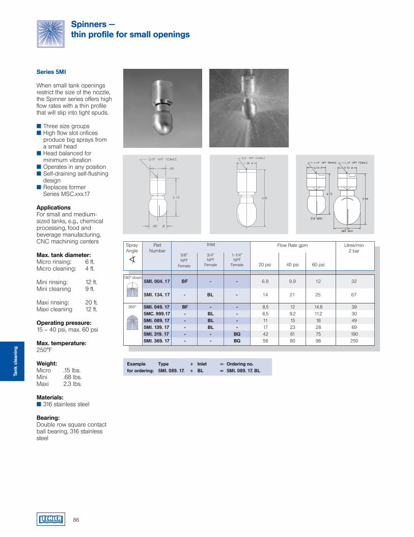
86
5MI. 049. 17 BF - - 8.5 12 14.8 39 5MC. 999. 17 - BL - 6.5 9.2 11.2 30 5MI. 089. 17 - BL - 11 15 18 49 5MI. 139. 17 - BL - 17 23 28 69 5MI. 319. 17 - - BQ 42 61 75 190 5MI. 369. 17 - - BQ 56 80 98 250
5MI. 004. 17 BF - - 6.8 9.9 12 32
5MI. 134. 17 - BL - 14 21 25 67
Series 5MI
When small tank openings restrict the size of the nozzle, the Spinner series offers high flow rates with a thin profile that will slip into tight spuds.
Three size groups High flow slot orifices
produce big sprays from a small head
Head balanced for minimum vibration
Operates in any position Self-draining self-flushing
design Replaces former
Series MSC.xxx.17
ApplicationsFor small and medium- sized tanks, e.g., chemical processing, food and beverage manufacturing, CNC machining centers
Max. tank diameter:Micro rinsing: 6 ft.Micro cleaning: 4 ft.
Mini rinsing: 12 ft.Mini cleaning 9 ft.
Maxi rinsing: 20 ft.Maxi cleaning 12 ft.
Operating pressure:15 – 40 psi, max. 60 psi
Max. temperature:250°F
Weight:Micro .15 lbs.Mini .68 lbs.Maxi 2.3 lbs.
Materials: 316 stainless steel
Bearing:Double row square contact ball bearing, 316 stainless steel
Example Type + Inlet = Ordering no.for ordering: 5MI. 089. 17. + BL = 5MI. 089. 17. BL
360º
Flow Rate gpm
<)3/8" NPT
Female
PartNumber
SprayAngle
Litres/min 2 bar
20 psi 40 psi 60 psi
1-1/4" NPT
Female
Inlet
3/4" NPT
Female
180º down
Spinners — thin profile for small openings
Tank
cle
anin
g
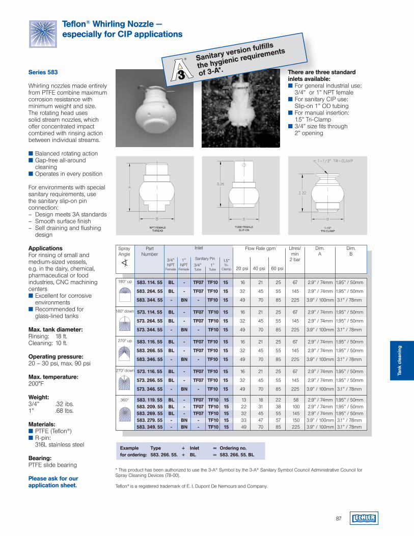
87
583. 114. 55 BL - TF07 TF10 15 16 21 25 67 2.9" / 74mm 1.95" / 50mm
583. 264. 55 BL - TF07 TF10 15 32 45 55 145 2.9" / 74mm 1.95" / 50mm
583. 344. 55 - BN - TF10 15 49 70 85 225 3.9" / 100mm 3.1" / 78mm
Teflon® Whirling Nozzle — especially for CIP applications
Example Type + Inlet = Ordering no.for ordering: 583. 266. 55. + BL = 583. 266. 55. BL
* This product has been authorized to use the 3-A® Symbol by the 3-A® Sanitary Symbol Council Administrative Council for Spray Cleaning Devices (78-00).
Teflon® is a registered trademark of E. I. Dupont De Nemours and Company.
Sanitary version fulfills
the hygienic requirements
of 3-A*.
NPT FEMALETHREAD
TUBE FEMALESLIP-ON
1-1/2"TRI-CLAMP
360º
270º up
270º down
Series 583
Whirling nozzles made entirelyfrom PTFE combine maximum corrosion resistance with minimum weight and size. The rotating head uses solid stream nozzles, which offer concentrated impact combined with rinsing action between individual streams.
Balanced rotating action Gap-free all-around
cleaning Operates in every position
For environments with special sanitary requirements, use the sanitary slip-on pin connection:– Design meets 3A standards– Smooth surface finish– Self draining and flushing
design
ApplicationsFor rinsing of small and medium-sized vessels, e.g. in the dairy, chemical, pharmaceutical or food industries, CNC machining centers Excellent for corrosive
environments Recommended for
glass-lined tanks
Max. tank diameter:Rinsing: 18 ft.Cleaning: 10 ft.
Operating pressure:20 – 30 psi, max. 90 psi
Max. temperature:200°F
Weight:3/4” .32 ibs.1” .68 lbs.
Materials: PTFE (Teflon®) R-pin:
316L stainless steel
Bearing:PTFE slide bearing
Please ask for our application sheet.
There are three standard inlets available: For general industrial use:
3/4” or 1” NPT female For sanitary CIP use:
Slip-on 1” OD tubing For manual insertion:
1.5” Tri-Clamp 3/4” size fits through
2” opening
180º up
Flow Rate gpm
<) 3/4" NPT
Female
PartNumber
SprayAngle
Litres/min
2 bar
20 psi 40 psi 60 psi
1" NPT
Female
Inlet
1.5" Tri-
Clamp
180º down
Sanitary Pin
Dim.A
Dim.B
3/4" Tube
1" Tube
583. 119. 55 BL - TF07 TF10 15 13 18 22 58 2.9" / 74mm 1.95" / 50mm 583. 209. 55 BL - TF07 TF10 15 22 31 38 100 2.9" / 74mm 1.95" / 50mm 583. 269. 55 BL - TF07 TF10 15 32 45 55 145 2.9" / 74mm 1.95" / 50mm 583. 279. 55 - BN - TF10 15 33 47 57 150 3.9" / 100mm 3.1" / 78mm 583. 349. 55 - BN - TF10 15 49 70 85 225 3.9" / 100mm 3.1" / 78mm
583. 116. 55 BL - TF07 TF10 15 16 21 25 67 2.9" / 74mm 1.95" / 50mm
583. 266. 55 BL - TF07 TF10 15 32 45 55 145 2.9" / 74mm 1.95" / 50mm
583. 346. 55 - BN - TF10 15 49 70 85 225 3.9" / 100mm 3.1" / 78mm
573. 114. 55 BL - TF07 TF10 15 16 21 25 67 2.9" / 74mm 1.95" / 50mm
573. 264. 55 BL - TF07 TF10 15 32 45 55 145 2.9" / 74mm 1.95" / 50mm
573. 344. 55 - BN - TF10 15 49 70 85 225 3.9" / 100mm 3.1" / 78mm
573. 116. 55 BL - TF07 TF10 15 16 21 25 67 2.9" / 74mm 1.95" / 50mm
573. 266. 55 BL - TF07 TF10 15 32 45 55 145 2.9" / 74mm 1.95" / 50mm
573. 346. 55 - BN - TF10 15 49 70 85 225 3.9" / 100mm 3.1" / 78mm
Tank
cle
anin
g
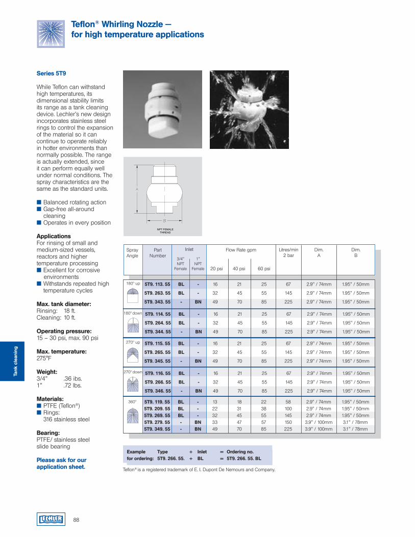
88
NPT FEMALETHREAD
270º up
270º down
Series 5T9
While Teflon can withstand high temperatures, its dimensional stability limits its range as a tank cleaning device. Lechler’s new design incorporates stainless steel rings to control the expansion of the material so it can continue to operate reliably in hotter environments than normally possible. The range is actually extended, since it can perform equally well under normal conditions. The spray characteristics are the same as the standard units.
Balanced rotating action Gap-free all-around
cleaning Operates in every position
ApplicationsFor rinsing of small and medium-sized vessels, reactors and higher temperature processing Excellent for corrosive environments Withstands repeated high
temperature cycles
Max. tank diameter:Rinsing: 18 ft.Cleaning: 10 ft.
Operating pressure:15 – 30 psi, max. 90 psi
Max. temperature:275°F
Weight:3/4” .36 ibs.1” .72 lbs.
Materials: PTFE (Teflon®) Rings:
316 stainless steel
Bearing:PTFE/ stainless steel slide bearing
Please ask for our application sheet.
Example Type + Inlet = Ordering no.for ordering: 5T9. 266. 55. + BL = 5T9. 266. 55. BL
Teflon® is a registered trademark of E. I. Dupont De Nemours and Company.
360º
Flow Rate gpm
<)3/4" NPT
Female
PartNumber
SprayAngle
Litres/min 2 bar
20 psi 40 psi 60 psi
1" NPT
Female
Inlet Dim.A
Dim.B
180º up
180º down
Teflon® Whirling Nozzle — for high temperature applications
5T9. 116. 55 BL - 16 21 25 67 2.9" / 74mm 1.95" / 50mm
5T9. 266. 55 BL - 32 45 55 145 2.9" / 74mm 1.95" / 50mm
5T9. 346. 55 - BN 49 70 85 225 2.9" / 74mm 1.95" / 50mm
5T9. 115. 55 BL - 16 21 25 67 2.9" / 74mm 1.95" / 50mm
5T9. 265. 55 BL - 32 45 55 145 2.9" / 74mm 1.95" / 50mm
5T9. 345. 55 - BN 49 70 85 225 2.9" / 74mm 1.95" / 50mm
5T9. 119. 55 BL - 13 18 22 58 2.9" / 74mm 1.95" / 50mm 5T9. 209. 55 BL - 22 31 38 100 2.9" / 74mm 1.95" / 50mm 5T9. 269. 55 BL - 32 45 55 145 2.9" / 74mm 1.95" / 50mm 5T9. 279. 55 - BN 33 47 57 150 3.9" / 100mm 3.1" / 78mm 5T9. 349. 55 - BN 49 70 85 225 3.9" / 100mm 3.1" / 78mm
5T9. 114. 55 BL - 16 21 25 67 2.9" / 74mm 1.95" / 50mm
5T9. 264. 55 BL - 32 45 55 145 2.9" / 74mm 1.95" / 50mm
5T9. 344. 55 - BN 49 70 85 225 2.9" / 74mm 1.95" / 50mm
5T9. 113. 55 BL - 16 21 25 67 2.9" / 74mm 1.95" / 50mm
5T9. 263. 55 BL - 32 45 55 145 2.9" / 74mm 1.95" / 50mm
5T9. 343. 55 - BN 49 70 85 225 2.9" / 74mm 1.95" / 50mm
Tank
cle
anin
g
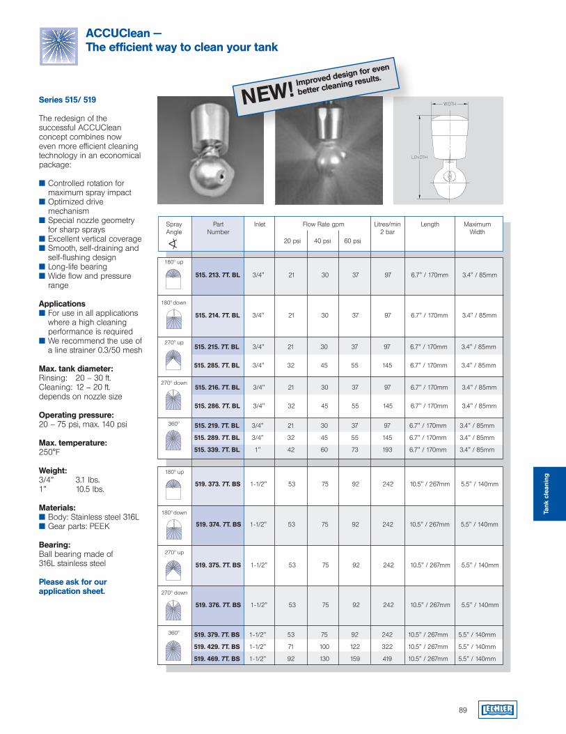
89
ACCUClean — The efficient way to clean your tank
Improved design for even
better cleaning results.
NEW!Series 515/ 519
The redesign of the successful ACCUClean concept combines now even more efficient cleaning technology in an economical package:
Controlled rotation for maximum spray impact
Optimized drive mechanism
Special nozzle geometry for sharp sprays
Excellent vertical coverage Smooth, self-draining and
self-flushing design Long-life bearing Wide flow and pressure
range
Applications For use in all applications
where a high cleaning performance is required
We recommend the use of a line strainer 0.3/50 mesh
Max. tank diameter:Rinsing: 20 – 30 ft.Cleaning: 12 – 20 ft.depends on nozzle size
Operating pressure:20 – 75 psi, max. 140 psi
Max. temperature:250°F
Weight:3/4” 3.1 lbs.1” 10.5 lbs.
Materials: Body: Stainless steel 316L Gear parts: PEEK
Bearing:Ball bearing made of 316L stainless steel
Please ask for our application sheet.
Flow Rate gpm
<)
InletPartNumber
SprayAngle
Litres/min 2 bar
Length MaximumWidth
360º
20 psi 40 psi 60 psi
360º
270º up
180º up
180º down
180º up
180º down
270º down
270º up
270º down
519. 379. 7T. BS 1-1/2" 53 75 92 242 10.5" / 267mm 5.5" / 140mm
519. 429. 7T. BS 1-1/2" 71 100 122 322 10.5" / 267mm 5.5" / 140mm
519. 469. 7T. BS 1-1/2" 92 130 159 419 10.5" / 267mm 5.5" / 140mm
519. 374. 7T. BS 1-1/2" 53 75 92 242 10.5" / 267mm 5.5" / 140mm
519. 373. 7T. BS 1-1/2" 53 75 92 242 10.5" / 267mm 5.5" / 140mm
515. 219. 7T. BL 3/4" 21 30 37 97 6.7" / 170mm 3.4" / 85mm
515. 289. 7T. BL 3/4" 32 45 55 145 6.7" / 170mm 3.4" / 85mm
515. 339. 7T. BL 1" 42 60 73 193 6.7" / 170mm 3.4" / 85mm
515. 214. 7T. BL 3/4" 21 30 37 97 6.7" / 170mm 3.4" / 85mm
515. 213. 7T. BL 3/4" 21 30 37 97 6.7" / 170mm 3.4" / 85mm
515. 215. 7T. BL 3/4" 21 30 37 97 6.7" / 170mm 3.4" / 85mm 515. 285. 7T. BL 3/4" 32 45 55 145 6.7" / 170mm 3.4" / 85mm
519. 375. 7T. BS 1-1/2" 53 75 92 242 10.5" / 267mm 5.5" / 140mm
519. 376. 7T. BS 1-1/2" 53 75 92 242 10.5" / 267mm 5.5" / 140mm
515. 216. 7T. BL 3/4" 21 30 37 97 6.7" / 170mm 3.4" / 85mm 515. 286. 7T. BL 3/4" 32 45 55 145 6.7" / 170mm 3.4" / 85mm
Tank
cle
anin
g
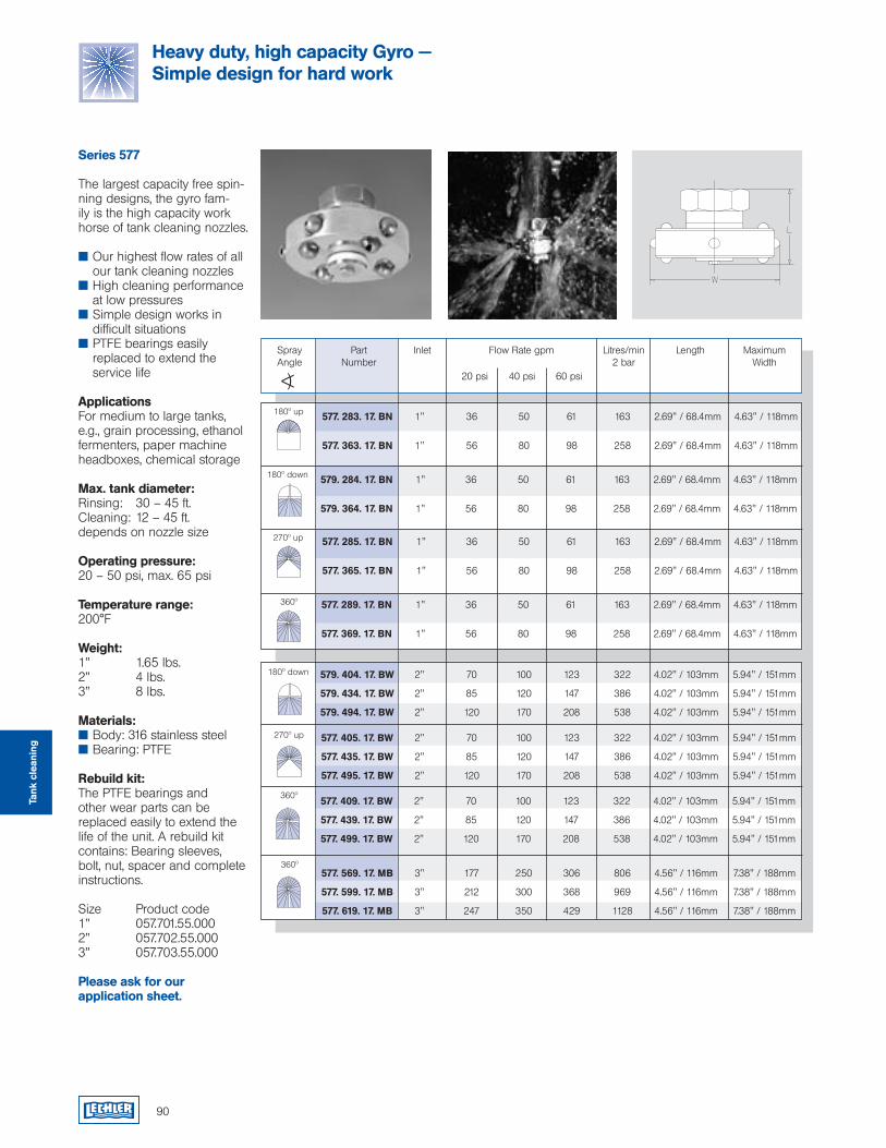
90
Series 577
The largest capacity free spin-ning designs, the gyro fam-ily is the high capacity work horse of tank cleaning nozzles.
Our highest flow rates of all our tank cleaning nozzles
High cleaning performance at low pressures
Simple design works in difficult situations
PTFE bearings easily replaced to extend the service life
ApplicationsFor medium to large tanks, e.g., grain processing, ethanol fermenters, paper machine headboxes, chemical storage
Max. tank diameter:Rinsing: 30 – 45 ft.Cleaning: 12 – 45 ft.depends on nozzle size
Operating pressure:20 – 50 psi, max. 65 psi
Temperature range:200°F
Weight:1” 1.65 lbs.2” 4 lbs.3” 8 lbs.
Materials: Body: 316 stainless steel Bearing: PTFE
Rebuild kit:The PTFE bearings and other wear parts can be replaced easily to extend the life of the unit. A rebuild kit contains: Bearing sleeves, bolt, nut, spacer and complete instructions.
Size Product code1” 057.701.55.0002” 057.702.55.0003” 057.703.55.000
Please ask for our application sheet.
Flow Rate gpm
<)
InletPartNumber
SprayAngle
Litres/min 2 bar
Length MaximumWidth
20 psi 40 psi 60 psi
180º up
180º down
270º up
360º
360º
360º
180º down
270º up
Heavy duty, high capacity Gyro — Simple design for hard work
Tank
cle
anin
g
577. 283. 17. BN 1" 36 50 61 163 2.69" / 68.4mm 4.63" / 118mm 577. 363. 17. BN 1" 56 80 98 258 2.69" / 68.4mm 4.63" / 118mm
577. 289. 17. BN 1" 36 50 61 163 2.69" / 68.4mm 4.63" / 118mm 577. 369. 17. BN 1" 56 80 98 258 2.69" / 68.4mm 4.63" / 118mm
577. 285. 17. BN 1" 36 50 61 163 2.69" / 68.4mm 4.63" / 118mm 577. 365. 17. BN 1" 56 80 98 258 2.69" / 68.4mm 4.63" / 118mm
577. 405. 17. BW 2" 70 100 123 322 4.02" / 103mm 5.94" / 151mm
577. 435. 17. BW 2" 85 120 147 386 4.02" / 103mm 5.94" / 151mm
577. 495. 17. BW 2" 120 170 208 538 4.02" / 103mm 5.94" / 151mm
577. 409. 17. BW 2" 70 100 123 322 4.02" / 103mm 5.94" / 151mm
577. 439. 17. BW 2" 85 120 147 386 4.02" / 103mm 5.94" / 151mm
577. 499. 17. BW 2" 120 170 208 538 4.02" / 103mm 5.94" / 151mm
577. 569. 17. MB 3" 177 250 306 806 4.56" / 116mm 7.38" / 188mm
577. 599. 17. MB 3" 212 300 368 969 4.56" / 116mm 7.38" / 188mm
577. 619. 17. MB 3" 247 350 429 1128 4.56" / 116mm 7.38" / 188mm
579. 284. 17. BN 1" 36 50 61 163 2.69" / 68.4mm 4.63" / 118mm 579. 364. 17. BN 1" 56 80 98 258 2.69" / 68.4mm 4.63" / 118mm
579. 404. 17. BW 2" 70 100 123 322 4.02" / 103mm 5.94" / 151mm
579. 434. 17. BW 2" 85 120 147 386 4.02" / 103mm 5.94" / 151mm
579. 494. 17. BW 2" 120 170 208 538 4.02" / 103mm 5.94" / 151mm
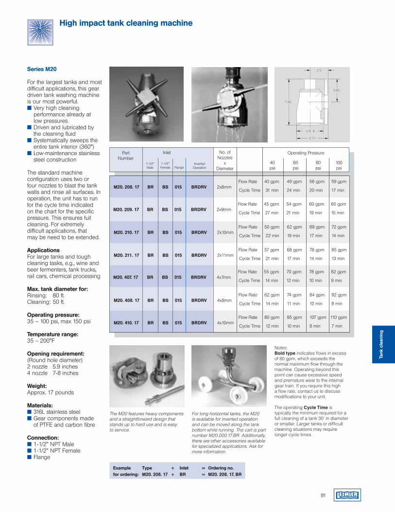
Series M20
For the largest tanks and most difficult applications, this gear driven tank washing machine is our most powerful. Very high cleaning
performance already at low pressures Driven and lubricated by
the cleaning fluid Systematically sweeps the
entire tank interior (360°) Low-maintenance stainless
steel construction
The standard machine configuration uses two or four nozzles to blast the tank walls and rinse all surfaces. In operation, the unit has to run for the cycle time indicated on the chart for the specific pressure. This ensures full cleaning. For extremely difficult applications, that may be need to be extended.
ApplicationsFor large tanks and tough cleaning tasks, e.g., wine and beer fermenters, tank trucks, rail cars, chemical processing
Max. tank diameter for: Rinsing: 80 ft.Cleaning: 50 ft.
Operating pressure:35 – 100 psi, max 150 psi
Temperature range: 35 – 200°F
Opening requirement: (Round hole diameter)2 nozzle 5.9 inches4 nozzle 7-8 inches
Weight: Approx. 17 pounds
Materials: 316L stainless steel Gear components made
of PTFE and carbon fibre
Connection: 1-1/2” NPT Male 1-1/2” NPT Female Flange
Notes:Bold type indicates flows in excess of 80 gpm, which exceeds the normal maximum flow through the machine. Operating beyond this point can cause excessive speed and premature wear to the internal gear train. If you require this high a flow rate, contact us to discuss modifications to your unit.
The operating Cycle Time is typically the minimum required for a full cleaning of a tank 30' in diameter or smaller. Larger tanks or difficult cleaning situations may require longer cycle times.
The M20 features heavy components and a straightforward design that stands up to hard use and is easy to service.
For long horizontal tanks, the M20 is available for inverted operation and can be moved along the tank bottom while running. The cart is part number M20.000.17.BR. Additionally, there are other accessories available for specialized applications. Ask for more information.
91
High impact tank cleaning machine
Example Type + Inlet = Ordering no.for ordering: M20. 208. 17 + BR = M20. 208. 17. BR
No. of Nozzles
xDiameter
PartNumber
Inlet Operating Pressure
40 60 80 100 psi psi psi psi
1-1/2" Male
1-1/2" Female Flange
InvertedOperation
Flow Rate 40 gpm 49 gpm 56 gpm 59 gpm
M20. 208. 17 BR BS 015 BRDRV 2x8mm Cycle Time 31 min 24 min 20 min 17 min
Flow Rate 45 gpm 54 gpm 60 gpm 65 gpm
M20. 209. 17 BR BS 015 BRDRV 2x9mm Cycle Time 27 min 21 min 19 min 15 min
Flow Rate 50 gpm 62 gpm 69 gpm 72 gpm
M20. 210. 17 BR BS 015 BRDRV 2x10mm Cycle Time 22 min 19 min 17 min 14 min
Flow Rate 57 gpm 68 gpm 78 gpm 85 gpm
M20. 211. 17 BR BS 015 BRDRV 2x11mm Cycle Time 21 min 17 min 14 min 13 min
Flow Rate 55 gpm 70 gpm 78 gpm 82 gpm
M20. 407. 17 BR BS 015 BRDRV 4x7mm Cycle Time 14 min 12 min 10 min 9 min
Flow Rate 62 gpm 74 gpm 84 gpm 92 gpm
M20. 408. 17 BR BS 015 BRDRV 4x8mm Cycle Time 14 min 11 min 10 min 8 min
Flow Rate 80 gpm 95 gpm 107 gpm 110 gpm
M20. 410. 17 BR BS 015 BRDRV 4x10mm Cycle Time 12 min 10 min 8 min 7 min
Tank
cle
anin
g
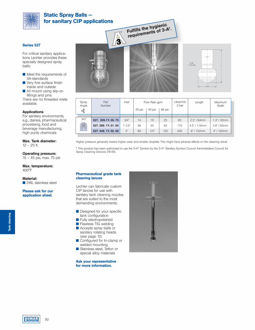
527. 209.1Y. 00. 75 3/4" 14 19 23 60 2.5" / 64mm 1.3" / 32mm
527. 289. 1Y. 01. 50 1-1/2" 36 50 62 170 4.5" / 116mm 2.6" / 65mm
527. 449. 1Y. 02. 00 2" 89 127 155 420 6" / 152mm 4" / 102mm
92
Static Spray Balls — for sanitary CIP applications
Fulfills the hygienic
requirements of 3-A*.
Series 527
For critical sanitary applica-tions Lechler provides these specially designed spray balls:
Meet the requirements of 3A-standards
Very fine surface finish inside and outside
All mount using slip-on fittings and pins.
There are no threaded inlets available.
ApplicationsFor sanitary environments, e.g., dairies, pharmaceutical processing, food and beverage manufacturing, high purity chemicals
Max. Tank diameter:12 – 25 ft.
Operating pressure:15 – 45 psi, max. 75 psi
Max. temperature:400°F
Material: 316L stainless steel
Please ask for our application sheet.
L
ø W
ø ca. 1-1,5 mm
Higher pressure generally means higher wear and smaller droplets. This might have adverse effects on the cleaning result.
* This product has been authorized to use the 3-A® Symbol by the 3-A® Sanitary Symbol Council Administrative Council for Spray Cleaning Devices (78-00).
360º
Flow Rate gpm
<)
InletPartNumber
SprayAngle
Litres/min 2 bar
Length MaximumWidth
20 psi 40 psi 60 psi
Pharmaceutical grade tank cleaning lances
Lechler can fabricate custom CIP lances for use with sanitary tank cleaning nozzles that are suited to the most demanding environments:
Designed for your specific tank configuration
Fully electropolished Flawless TIG welding Accepts spray balls or
sanitary rotating heads (see page 12)
Configured for tri-clamp or welded mounting Stainless steel, Teflon or
special alloy materials
Ask your representative for more information.
Tank
cle
anin
g
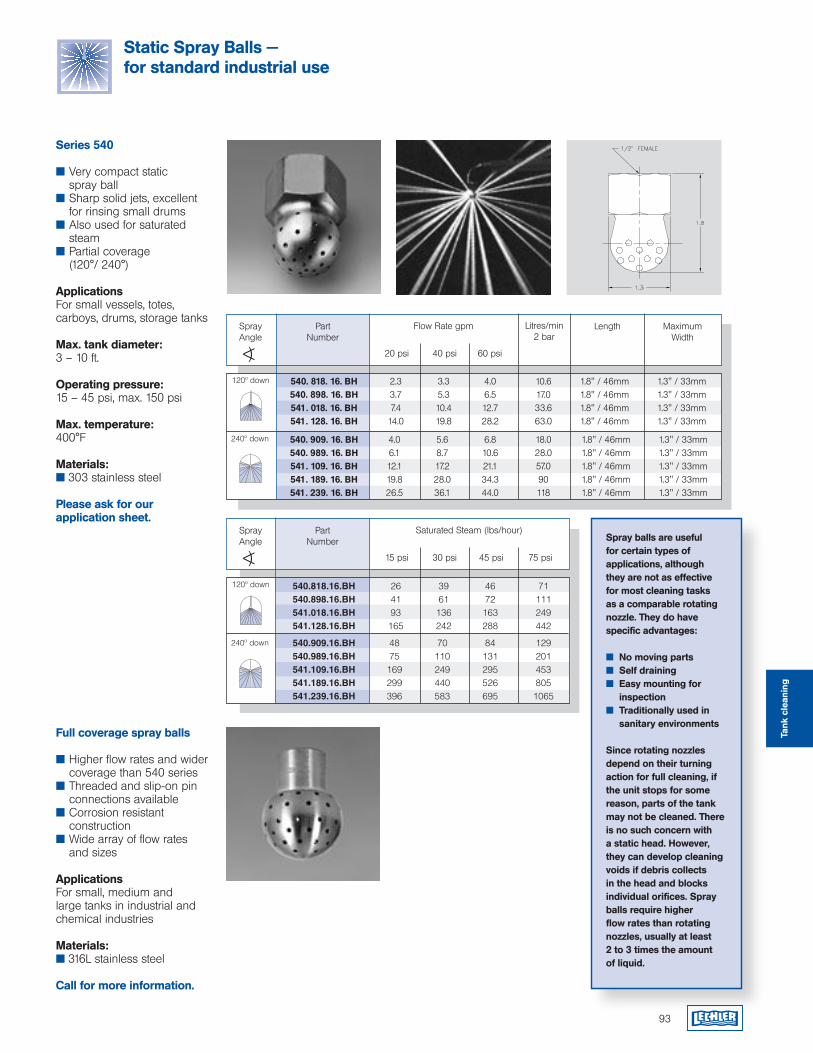
Spray balls are useful for certain types of applications, although they are not as effective for most cleaning tasks as a comparable rotating nozzle. They do have specific advantages:
No moving parts Self draining Easy mounting for
inspection Traditionally used in
sanitary environments
Since rotating nozzles depend on their turning action for full cleaning, if the unit stops for some reason, parts of the tank may not be cleaned. There is no such concern with a static head. However, they can develop cleaning voids if debris collects in the head and blocks individual orifices. Spray balls require higher flow rates than rotating nozzles, usually at least 2 to 3 times the amount of liquid.
Static Spray Balls — for standard industrial use
Series 540
Very compact static spray ball
Sharp solid jets, excellent for rinsing small drums
Also used for saturated steam
Partial coverage (120°/ 240°)
ApplicationsFor small vessels, totes, carboys, drums, storage tanks
Max. tank diameter:3 – 10 ft.
Operating pressure:15 – 45 psi, max. 150 psi
Max. temperature:400°F
Materials: 303 stainless steel
Please ask for our application sheet.
120º down
Flow Rate gpm
<)
PartNumber
SprayAngle
Litres/min 2 bar
20 psi 40 psi 60 psi
240º down
Length Maximum Width
120º down
Saturated Steam (lbs/hour)
<)
PartNumber
SprayAngle
15 psi 30 psi 45 psi 75 psi
240º down
Full coverage spray balls
Higher flow rates and wider coverage than 540 series
Threaded and slip-on pin connections available
Corrosion resistant construction
Wide array of flow rates and sizes
ApplicationsFor small, medium and large tanks in industrial and chemical industries
Materials: 316L stainless steel
Call for more information.
540. 909. 16. BH 4.0 5.6 6.8 18.0 1.8" / 46mm 1.3" / 33mm 540. 989. 16. BH 6.1 8.7 10.6 28.0 1.8" / 46mm 1.3" / 33mm 541. 109. 16. BH 12.1 17.2 21.1 57.0 1.8" / 46mm 1.3" / 33mm 541. 189. 16. BH 19.8 28.0 34.3 90 1.8" / 46mm 1.3" / 33mm 541. 239. 16. BH 26.5 36.1 44.0 118 1.8" / 46mm 1.3" / 33mm
540. 818. 16. BH 2.3 3.3 4.0 10.6 1.8" / 46mm 1.3" / 33mm 540. 898. 16. BH 3.7 5.3 6.5 17.0 1.8" / 46mm 1.3" / 33mm 541. 018. 16. BH 7.4 10.4 12.7 33.6 1.8" / 46mm 1.3" / 33mm 541. 128. 16. BH 14.0 19.8 28.2 63.0 1.8" / 46mm 1.3" / 33mm
Tank
cle
anin
g
540.818.16.BH 26 39 46 71 540.898.16.BH 41 61 72 111 541.018.16.BH 93 136 163 249 541.128.16.BH 165 242 288 442
540.909.16.BH 48 70 84 129 540.989.16.BH 75 110 131 201 541.109.16.BH 169 249 295 453 541.189.16.BH 299 440 526 805 541.239.16.BH 396 583 695 1065
93
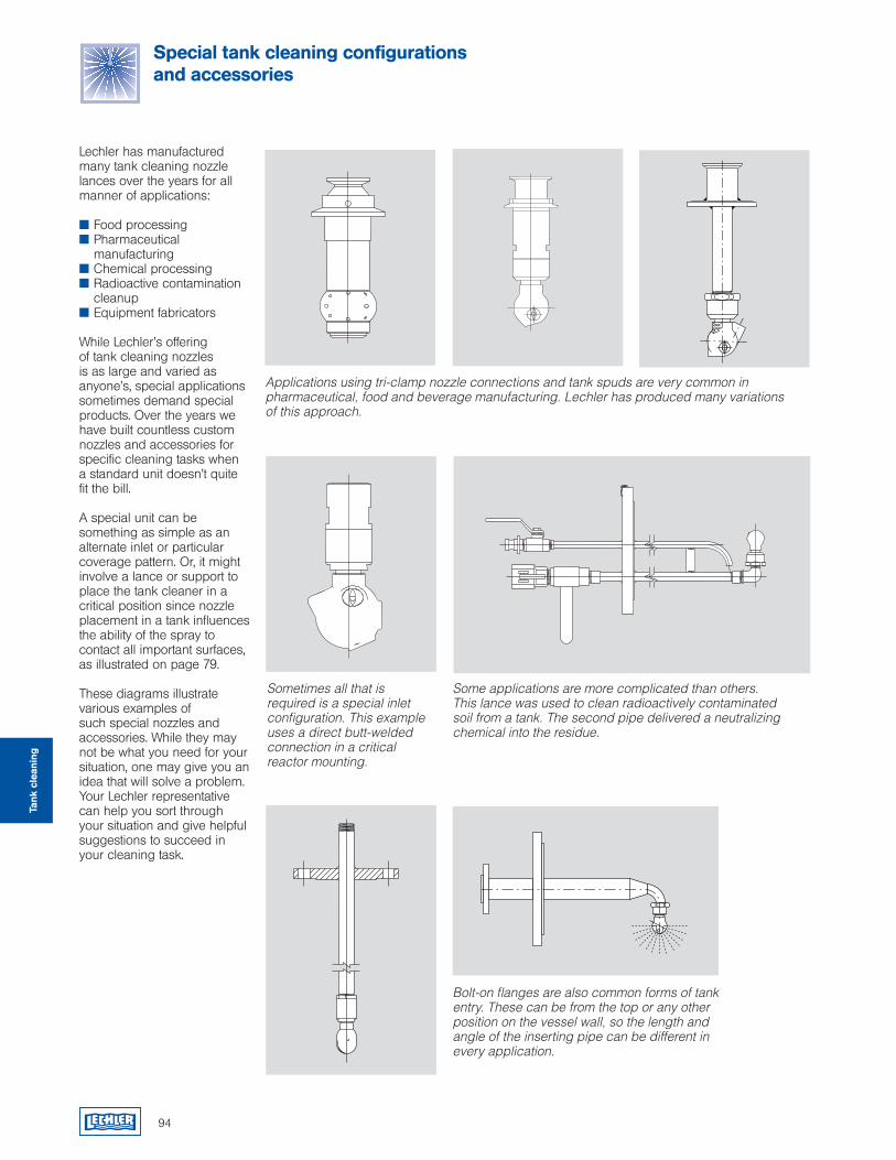
94
Lechler has manufactured many tank cleaning nozzle lances over the years for all manner of applications:
Food processing Pharmaceutical
manufacturing Chemical processing Radioactive contamination
cleanup Equipment fabricators
While Lechler’s offering of tank cleaning nozzles is as large and varied as anyone’s, special applications sometimes demand special products. Over the years we have built countless custom nozzles and accessories for specific cleaning tasks when a standard unit doesn’t quite fit the bill.
A special unit can be something as simple as an alternate inlet or particular coverage pattern. Or, it might involve a lance or support to place the tank cleaner in a critical position since nozzle placement in a tank influences the ability of the spray to contact all important surfaces, as illustrated on page 79.
These diagrams illustrate various examples of such special nozzles and accessories. While they may not be what you need for your situation, one may give you an idea that will solve a problem. Your Lechler representative can help you sort through your situation and give helpful suggestions to succeed in your cleaning task.
Applications using tri-clamp nozzle connections and tank spuds are very common in pharmaceutical, food and beverage manufacturing. Lechler has produced many variations of this approach.
Sometimes all that is required is a special inlet configuration. This example uses a direct butt-welded connection in a critical reactor mounting.
Some applications are more complicated than others. This lance was used to clean radioactively contaminated soil from a tank. The second pipe delivered a neutralizing chemical into the residue.
Bolt-on flanges are also common forms of tank entry. These can be from the top or any other position on the vessel wall, so the length and angle of the inserting pipe can be different in every application.
Special tank cleaning configurationsand accessories
Tank
cle
anin
g

Accessories
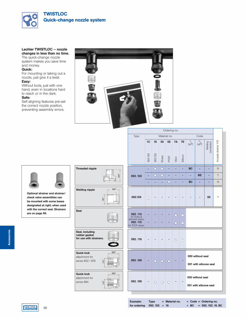
Threaded nipple
.925
"
96
TWISTLOCQuick-change nozzle system
Example: Type + Material no. + Code = Ordering no.for ordering 092. 102 + 16 + BC = 092. 102. 16. BC
Ordering no.
CodeType Material no.
1/4NPT
3/8NPT
Wel
ding
co
nnec
tion
304
SS
16 30 5E1C
303
SS
Bra
ss
PVD
F
7A
Vito
n
7E
Sili
con
BC
-
BC
-
BE
-
-
-
-
N
Y
N
-
-
-
-
-
-
-
-
-
-
-
-
-
092. 102
- - Y00 - - - - -092.104
-
-
-
-
-
-
-
-
092. 113
092. 115
- - - - 092. 116
- - -092. 106
- - - -092. 108
Optional strainer and strainer/check valve assemblies can be mounted with some bases designated at right, when used with the correct seal. Strainers are on page 98.
Welding nipple
Seal
Seal, including rubber gasket for use with strainers.
Quick-lockattachment for series 652 / 679
Quick-lockattachment for series 684
Lechler TWISTLOC — nozzle changes in less than no time. The quick-change nozzle system makes you save time and money.Quick:For mounting or taking out a nozzle, just give it a twist.Easy:Without tools, just with one hand, even in locations hard to reach or in the dark.Safe:Self aligning features pre-set the correct nozzle position, preventing assembly errors.
.985"
.925
"
.787"
.866"
.710"
.866"
.710"
Acce
pts
stra
iner
Y/N
for brass & stainless assys.
for PVDF assys.
Acc
esso
ries
000 without seal
001 with silicone seal
000 without seal
001 with silicone seal
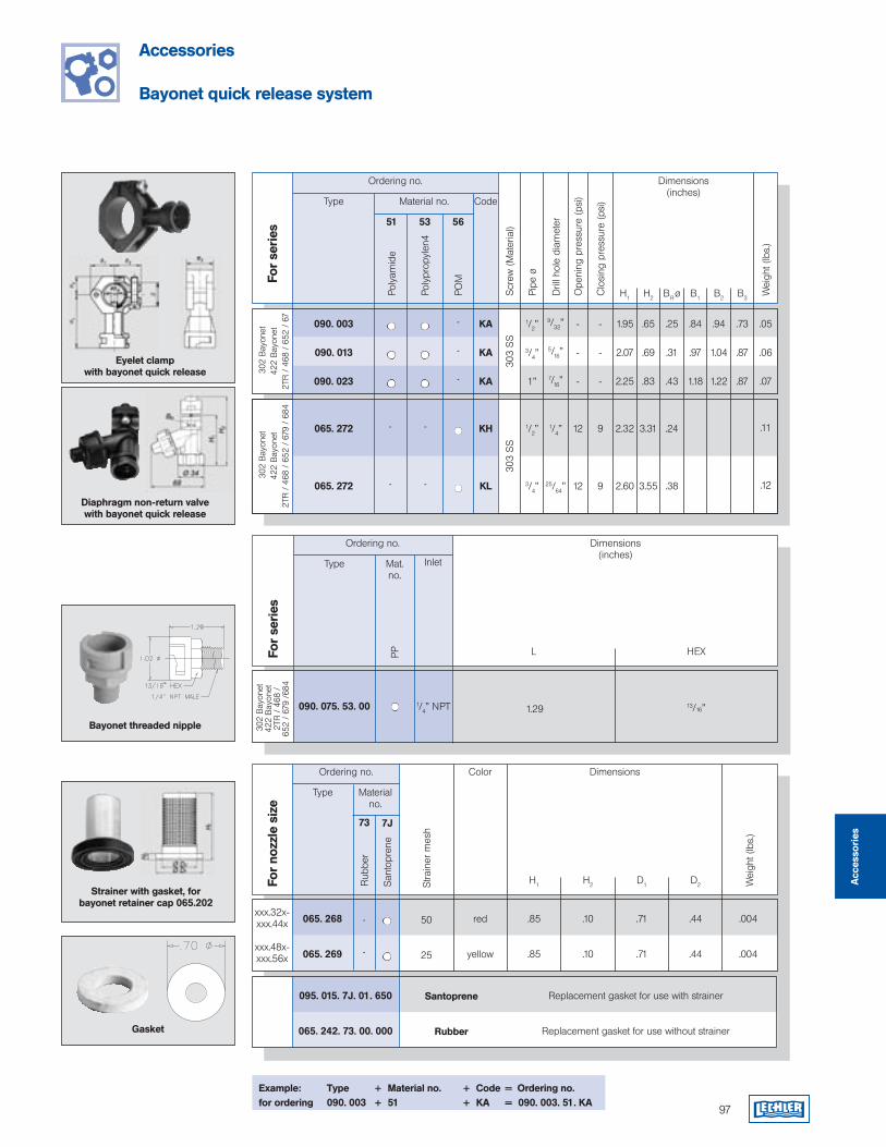
97
Accessories
Bayonet quick release system
Type
Poly
amid
e
For
seri
es
5351
Poly
prop
ylen
4
56
POM
1.95
2.07
2.25
.65
.69
.83
.25
.31
.43
.84
.97
1.18
.94
1.04
1.22
.73
.87
.87
.05
.06
.07
-
-
-
KA
KA
KA
302
Bay
onet
422
Bay
onet
2TR
/ 4
68 /
652
/ 6
7
090. 003
090. 013
090. 023
Code
H1 H2 BR ø B1 B2 B3
Wei
ght (
lbs.
)
2.32
2.60
3.31
3.55
.24
.38
.11
.12
-
-
-
-
KH
KL
302
Bay
onet
422
Bay
onet
2TR
/ 4
68 /
652
/ 6
79 /
684
065. 272
065. 272
Diaphragm non-return valve with bayonet quick release
Eyelet clamp with bayonet quick release
Dimensions(inches)
Material no.
Ordering no.
Ordering no.
Stra
iner
mes
h
W
eigh
t (lb
s.)
Color Dimensions
H1 H2 D1 D2
Type Materialno.
For
nozz
le s
ize
7J
San
topr
ene
50
25
red
yellow
.85
.85
.10
.10
.71
.71
.44
.44
.004
.004
xxx.32x-xxx.44x
xxx.48x-xxx.56x
065. 268
065. 269
Strainer with gasket, for bayonet retainer cap 065.202
Scr
ew (
Mat
eria
l)30
3 S
S30
3 S
S
-
-
-
-
-
-
12
12
9
9
Ope
ning
pre
ssur
e (p
si)
Clo
sing
pre
ssur
e (p
si)
1/2”
3/4”
1”
9/32”
5/16”
7/16”
1/2”
3/4”
1/4”
25/64”
Pipe
ø
Dril
l hol
e di
amet
er
Replacement gasket for use with strainer
Replacement gasket for use without strainer
Example: Type + Material no. + Code = Ordering no.for ordering 090. 003 + 51 + KA = 090. 003. 51. KA
73
Rub
ber
-
-
Ordering no. Dimensions(inches)
L HEX
Type Mat.no.
For
seri
es
PP
1.29 13/16”090. 075. 53. 00 1/4” NPT
302
Bay
onet
422
Bay
onet
2TR
/ 4
68 /
65
2 /
679
/684
Inlet
Bayonet threaded nipple
Gasket
Acc
esso
ries
095. 015. 7J. 01. 650
065. 242. 73. 00. 000
Santoprene
Rubber
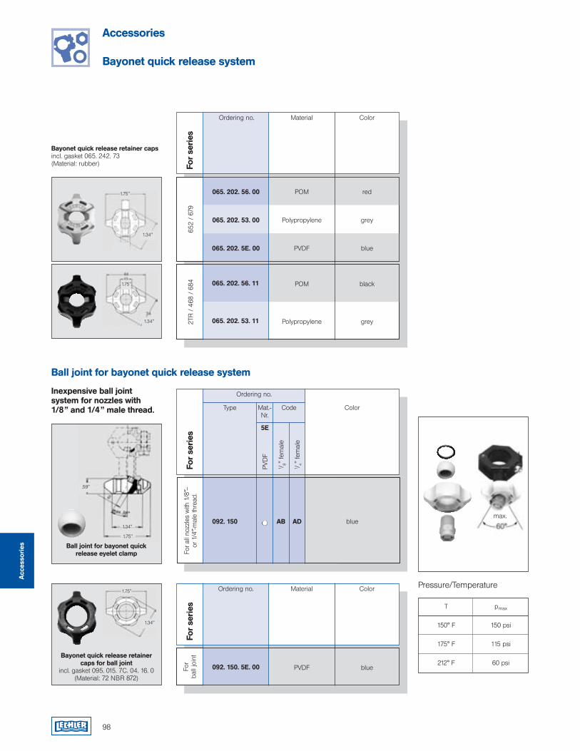
Accessories
Bayonet quick release system
Acc
esso
ries
98
blue
T pmax
150° F 150 psi
175° F 115 psi
212° F 60 psi
Ball joint for bayonet quick release system
Ordering no.
Type Mat.-Nr.
For
seri
es
5E
PVD
F
1 /8"
fem
ale
1 /4"
fem
ale
Code Color
AB AD
For a
ll no
zzle
s w
ith 1
/8″−
or
1/4
″-mal
e th
read
.
092. 150
Ball joint for bayonet quick release eyelet clamp
Bayonet quick release retainercaps for ball joint
incl. gasket 095. 015. 7C. 04. 16. 0(Material: 72 NBR 872)
Ordering no. Material Color
For
seri
esFo
r ba
ll jo
int
092. 150. 5E. 00 PVDF blue
max.
Ordering no. Material Color
652
/ 67
9 065. 202. 56. 00
065. 202. 53. 00
065. 202. 5E. 00
POM
Polypropylene
PVDF
red
grey
blue
2TR
/ 4
68 /
684
065. 202. 56. 11
065. 202. 53. 11
POM
Polypropylene
black
grey
Bayonet quick release retainer capsincl. gasket 065. 242. 73(Material: rubber)
Inexpensive ball joint system for nozzles with 1/8” and 1/4” male thread.
Pressure/Temperature
For
seri
es1.75"
1.34"
1.75"
1.34"
.59"
1.34"
1.75"
1.75"
1.34"
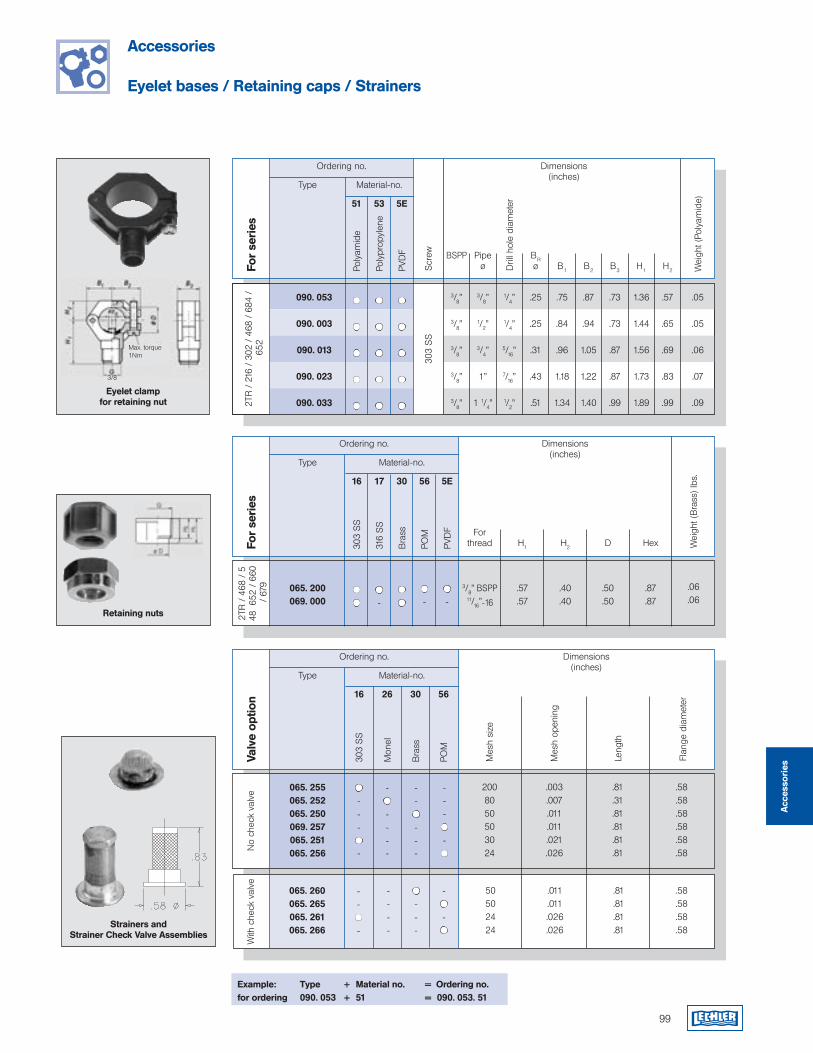
99
Accessories
Eyelet bases / Retaining caps / Strainers
Ordering no. Dimensions(inches)
Pipeø
BSPP BRø B1 B2 B3 H1 H2
Type Material-no.
Poly
amid
e
For
seri
es
53 5E51
Poly
prop
ylen
e
PVD
F
3/8”
1/2”
3/4”
1”
1 1/4”
3/8”
3/8”
3/8”
3/8”
3/8”
1/4”
1/4”
5/16”
7/16”
1/2”
.25
.25
.31
.43
.51
.75
.84
.96
1.18
1.34
.87
.94
1.05
1.22
1.40
.73
.73
.87
.87
.99
1.36
1.44
1.56
1.73
1.89
.57
.65
.69
.83
.99
.05
.05
.06
.07
.09
2TR
/ 2
16 /
302
/ 4
68 /
684
/ 6
52
090. 053
090. 003
090. 013
090. 023
090. 033
Wei
ght (
Poly
amid
e)
Scr
ew30
3 S
S
Eyelet clamp for retaining nut
3/8
Max. torque 1Nm
Ordering no. Dimensions(inches)
Type Material-no.
For
seri
es
16 17
303
SS
316
SS
30
Bra
ss
56
POM
5E
PVD
F Forthread H1 H2 D Hex W
eigh
t (B
rass
) lbs
.
3/8” BSPP11/16”-16
2TR
/ 4
68 /
548
652
/ 6
60 /
679
065. 200069. 000
.57
.57.40.40
.50
.50.87.87
-
-
-Retaining nuts
Dril
l hol
e di
amet
er
.06
.06
Ordering no. Dimensions(inches)
Type Material-no.
Valv
e op
tion 16 26
303
SS
Mon
el
30
Bra
ss
56
POM
Flan
ge d
iam
eter
---
-No
chec
k va
lve 065. 255
065. 252065. 250069. 257065. 251065. 256
2008050503024
Strainers and Strainer Check Valve Assemblies
Leng
th
Mes
h op
enin
g
Mes
h si
ze
-
----
--
---
---
-
--
-
With
che
ck v
alve
----
---
-
-
.003
.007.011.011.021.026
.81
.31
.81
.81
.81
.81
.58
.58
.58
.58
.58
.58
50502424
.011
.011.026.026
.81
.81
.81
.81
.58
.58
.58
.58
Acc
esso
ries
065. 260065. 265065. 261065. 266
Example: Type + Material no. = Ordering no.for ordering 090. 053 + 51 = 090. 053. 51
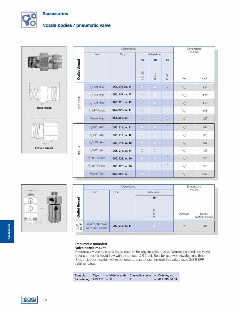
Ordering no. Dimensions(inches)
Hex Length
Inlet Type
Out
let t
hrea
d
1/4” NPT Male
3/8” NPT Male
1/2” NPT Male
1/4” NPT Female
Retainer Cap
11/16”
11/16”
7/8”
11/16”
7/8”
1.44
1.25
1.38
1.25
0.57
3/8"
BS
PP
Male thread
100
Accessories
Nozzle bodies / pneumatic valve
Pneumatic actuated valve nozzle mountPneumatic valve acts as a liquid shut-off for any tip style nozzle. Normally closed, the valve opens to permit liquid flow with air pressure>30 psi. Best for use with nozzles less than 1 gpm. Larger nozzles will experience pressure loss through the valve. Uses 3/8 BSPP retainer caps.
Example: Type + Material code Connection code = Ordering no.for ordering 065. 215 + 16 11 = 065. 215. 16. 11
Female thread
Material-no.
303
SS
30 5616
Bra
ss
POM
-
-
-
-
1/8” NPT Male
1/4” NPT Male
3/8” NPT Male
1/2” NPT Male
1/4” NPT Female
3/8” NPT Female
Retainer Cap
11/1
6 –1
6
065. 211. xx. 11
065. 215. xx. 10
065. 211. xx. 10
065. 211. xx. 14
065. 221. xx. 10
065. 220. xx. 10
069. 000. xx
-
-
-
-
-
-
-
11/16”
11/16”
11/16”
7/8”
11/16”
7/8”
7/8”
1.44
1.25
1.38
1.25
1.25
1.25
0.57
Ordering no. Dimensions(inches)
Diameter Length(without nozzle)
Inlet Type
Out
let t
hrea
d
Liquid: 1/4” NPT MaleAir: 1/8” NPT Female
1.5 3.0
3/8"
B
SPP 099. 215. xx. 11
Material-no.
303
SS
16
Acc
esso
ries
065. 215. xx. 11
065. 215. xx. 12
065. 211. xx. 15
065. 221. xx. 11
065. 200. xx
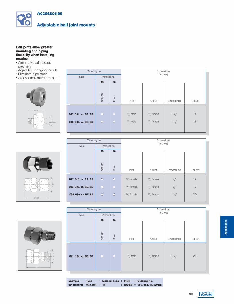
101
Accessories
Adjustable ball joint mounts
Ball joints allow greater mounting and piping flexibility when installing nozzles:• Aim individual nozzles precisely• Adjust for changing targets• Eliminate pipe strain• 200 psi maximum pressure
Example: Type + Material code + Inlet = Ordering no.for ordering 092. 084 + 16 + BA/BB = 092. 084. 16. BA/BB
Ordering no. Dimensions(inches)
Type Material-no.
16 30
303
SS
Bra
ss
092. 084. xx. BA. BB
092. 085. xx. BC. BD
1/8” male
1/4” male
1/8” female
1/4” female
1 3/8”
1 3/8”
1.4
1.6
Ordering no. Dimensions(inches)
Type Material-no.
16 30
303
SS
Bra
ss
092. 010. xx. BB. BB
092. 020. xx. BD. BD
092. 030. xx. BF. BF
1/8” female
1/4” female
3/8” female
1/8” female
1/4” female
3/8” female
7/8”
7/8”
1 1/8”
1.7
1.7
2.0
Ordering no. Dimensions(inches)
Type Material-no.
16 30
303
SS
Bra
ss
091. 124. xx. BE. BF 3/8” male 3/8” female 1 1/8” 2.1
Inlet Outlet Largest Hex Length
Inlet Outlet Largest Hex Length
Inlet Outlet Largest Hex Length
Acc
esso
ries
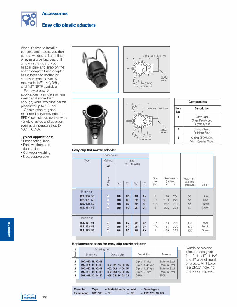
102
Replacement parts for easy clip nozzle adapter
Accessories
Easy clip plastic adapters
Components
Item Description No.
1 Body Base Glass Reinforced Polypropylene
2 Spring Clamp Stainless Steel
3 O-ring EPDM, Std. Viton, Special Order
Nozzle bases and clips are designed for 1", 1-1/4", 1-1/2" and 2" pipe of metal or plastic. All it takes is a 21/32" hole, no threading required.
When it’s time to install a conventional nozzle, you don’t need a welder, half couplings or even a pipe tap. Just drill a hole in the side of your header pipe and snap on the nozzle adapter. Each adapter has a threaded mount for a conventional nozzle, with mounts in 1/8", 1/4", 3/8", and 1/2" NPTF available. For low pressure applications, a single stainless steel clip is more than enough, while two clips permit pressures up to 125 psi. Construction of glass reinforced polypropylene and EPDM seal stands up to a wide variety of acids and caustics, even at temperatures up to 180°F (82°C).
Typical applications:• Phosphating lines• Parts washers and degreasing• Conveyor washing• Dust suppression
Example: Type + Material code + Inlet = Ordering no.for ordering 092. 180 + 16 + BB = 092. 120. 16. BB
Ordering no.
Dimensions(inches)X Y
Type Mat.-no.
53
Poly
pro
092. 180. 53092. 181. 53092. 182. 53092. 183. 53
11 1/41 1/22
BlueRed
PurpleGreen
Inlet("NPT female)
Pipe Size (in.)
Maximum working pressure Color
Single clip
1/8”1/4”
3/8”1/2”
BBBBBBBB
BDBDBDBD
BFBFBFBF
BHBHBHBH
1.701.892.022.25
2.012.212.302.54
70505035
092. 191. 53092. 192. 53092. 193. 53
1 1/41 1/22
RedPurpleGreen
Double clip
BBBBBB
BDBDBD
BFBFBF
BHBHBH
1.431.551.79
2.212.302.54
125125100
Easy clip flat nozzle adapter
Ordering no.
Single clip Double clip Description Material
Item
No.
2 092. 080. 15. 00. 05 Clip for 1" pipe Stainless Steel 2 092. 081. 15. 00. 05 092. 091. 15. 00. 05 Clip for 11/4" pipe Stainless Steel 2 092. 082. 15. 00. 05 092. 092. 15. 00. 05 Clip for 11/2" pipe Stainless Steel 2 092. 083. 15. 00. 05 092. 093. 15. 00. 05 Clip for 2" pipe Stainless Steel 3 095. 015. 6C. 04. 32 095. 015. 6C. 04. 32 O-Ring EPDM
Acc
esso
ries
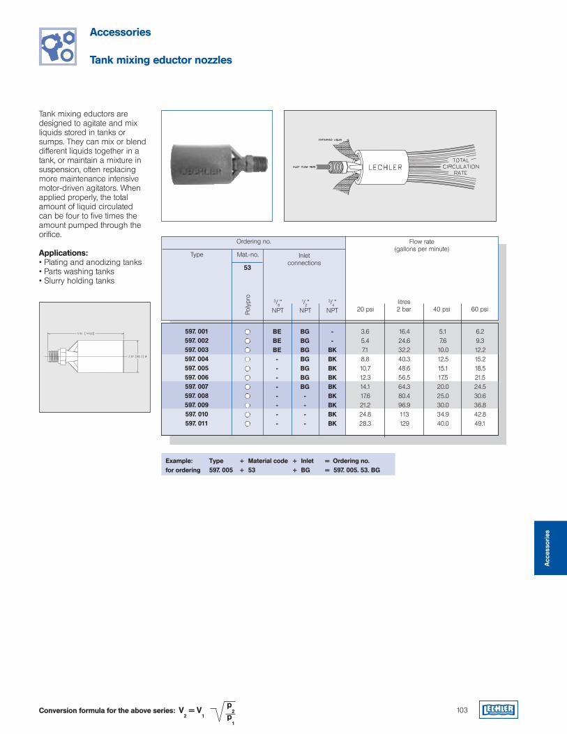
103
Accessories
Tank mixing eductor nozzles
Tank mixing eductors are designed to agitate and mix liquids stored in tanks or sumps. They can mix or blend different liquids together in a tank, or maintain a mixture in suspension, often replacing more maintenance intensive motor-driven agitators. When applied properly, the total amount of liquid circulated can be four to five times the amount pumped through the orifice.
Applications:• Plating and anodizing tanks• Parts washing tanks• Slurry holding tanks
V2 = V
1
p2
p1
Conversion formula for the above series:
Example: Type + Material code + Inlet = Ordering no.for ordering 597. 005 + 53 + BG = 597. 005. 53. BG
Ordering no. Flow rate(gallons per minute)
Type Mat.-no.
53
Poly
pro
597. 001597. 002597. 003597. 004597. 005597. 006597. 007597. 008597. 009597. 010597. 011
Inletconnections
20 psi3/8”NPT
1/2”NPT
3/4”NPT
BEBEBE--------
BGBGBGBGBGBGBG----
--
BKBKBKBKBKBKBKBKBK
3.65.47.18.810.712.314.117.621.224.828.3
litres2 bar 40 psi 60 psi
16.424.632.240.348.656.564.380.496.9113129
5.17.6
10.012.515.117.520.025.030.034.940.0
6.29.312.215.218.521.524.530.636.842.849.1
Acc
esso
ries
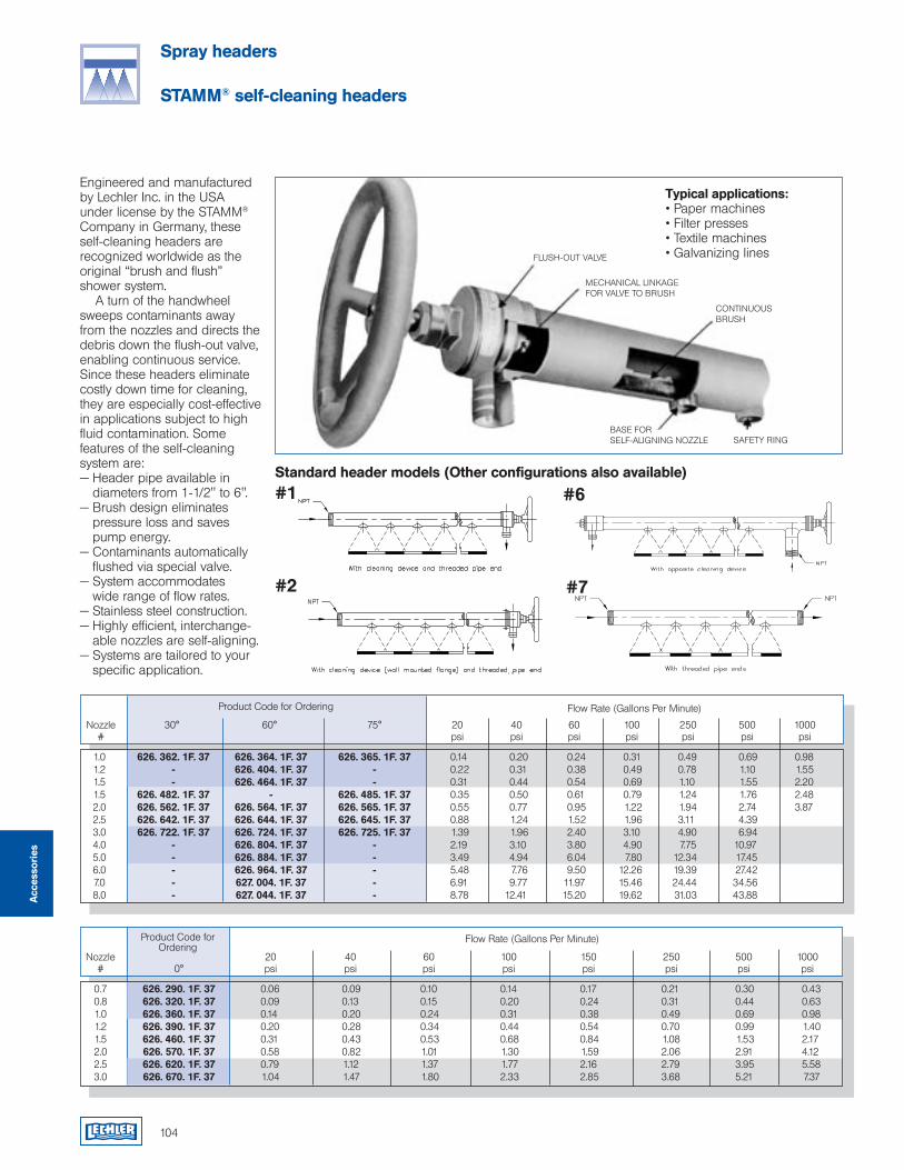
104
Spray headers
STAMM® self-cleaning headers
Engineered and manufactured by Lechler Inc. in the USA under license by the STAMM® Company in Germany, these self-cleaning headers are recognized worldwide as the original “brush and flush” shower system. A turn of the handwheel sweeps contaminants away from the nozzles and directs the debris down the flush-out valve, enabling continuous service. Since these headers eliminate costly down time for cleaning, they are especially cost-effective in applications subject to high fluid contamination. Some features of the self-cleaning system are:— Header pipe available in
diameters from 1-1/2" to 6".— Brush design eliminates
pressure loss and saves pump energy.
— Contaminants automatically flushed via special valve.
— System accommodates wide range of flow rates.
— Stainless steel construction.— Highly efficient, interchange-
able nozzles are self-aligning.— Systems are tailored to your
specific application.
#1
#2
#6
#7
Standard header models (Other configurations also available)
FLUSH-OUT VALVE
MECHANICAL LINKAGEFOR VALVE TO BRUSH
CONTINUOUS BRUSH
Typical applications:• Paper machines• Filter presses• Textile machines• Galvanizing lines
Product Code for Ordering
Nozzle 30° 60° 75° 20 40 60 100 250 500 1000 # psi psi psi psi psi psi psi
Flow Rate (Gallons Per Minute)
BASE FORSELF-ALIGNING NOZZLE SAFETY RING
Product Code for Ordering
Nozzle 20 40 60 100 150 250 500 1000 # 0° psi psi psi psi psi psi psi psi
Flow Rate (Gallons Per Minute)
0.7 626. 290. 1F. 37 0.06 0.09 0.10 0.14 0.17 0.21 0.30 0.43 0.8 626. 320. 1F. 37 0.09 0.13 0.15 0.20 0.24 0.31 0.44 0.63 1.0 626. 360. 1F. 37 0.14 0.20 0.24 0.31 0.38 0.49 0.69 0.98 1.2 626. 390. 1F. 37 0.20 0.28 0.34 0.44 0.54 0.70 0.99 1.40 1.5 626. 460. 1F. 37 0.31 0.43 0.53 0.68 0.84 1.08 1.53 2.17 2.0 626. 570. 1F. 37 0.58 0.82 1.01 1.30 1.59 2.06 2.91 4.12 2.5 626. 620. 1F. 37 0.79 1.12 1.37 1.77 2.16 2.79 3.95 5.58 3.0 626. 670. 1F. 37 1.04 1.47 1.80 2.33 2.85 3.68 5.21 7.37
Acc
esso
ries
1.0 626. 362. 1F. 37 626. 364. 1F. 37 626. 365. 1F. 37 0.14 0.20 0.24 0.31 0.49 0.69 0.98 1.2 - 626. 404. 1F. 37 - 0.22 0.31 0.38 0.49 0.78 1.10 1.55 1.5 - 626. 464. 1F. 37 - 0.31 0.44 0.54 0.69 1.10 1.55 2.20 1.5 626. 482. 1F. 37 - 626. 485. 1F. 37 0.35 0.50 0.61 0.79 1.24 1.76 2.48 2.0 626. 562. 1F. 37 626. 564. 1F. 37 626. 565. 1F. 37 0.55 0.77 0.95 1.22 1.94 2.74 3.87 2.5 626. 642. 1F. 37 626. 644. 1F. 37 626. 645. 1F. 37 0.88 1.24 1.52 1.96 3.11 4.39 3.0 626. 722. 1F. 37 626. 724. 1F. 37 626. 725. 1F. 37 1.39 1.96 2.40 3.10 4.90 6.94 4.0 - 626. 804. 1F. 37 - 2.19 3.10 3.80 4.90 7.75 10.97 5.0 - 626. 884. 1F. 37 - 3.49 4.94 6.04 7.80 12.34 17.45 6.0 - 626. 964. 1F. 37 - 5.48 7.76 9.50 12.26 19.39 27.42 7.0 - 627. 004. 1F. 37 - 6.91 9.77 11.97 15.46 24.44 34.56 8.0 - 627. 044. 1F. 37 - 8.78 12.41 15.20 19.62 31.03 43.88
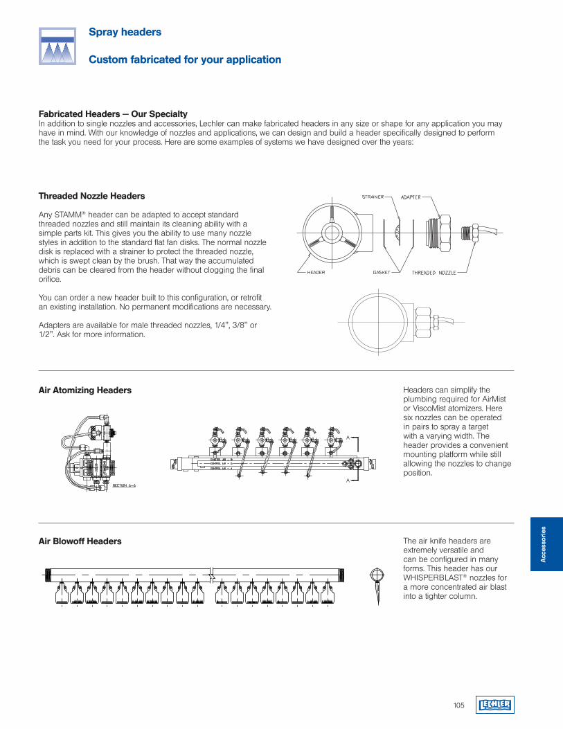
105
Threaded Nozzle Headers
Any STAMM® header can be adapted to accept standard threaded nozzles and still maintain its cleaning ability with a simple parts kit. This gives you the ability to use many nozzle styles in addition to the standard flat fan disks. The normal nozzle disk is replaced with a strainer to protect the threaded nozzle, which is swept clean by the brush. That way the accumulated debris can be cleared from the header without clogging the final orifice.
You can order a new header built to this configuration, or retrofit an existing installation. No permanent modifications are necessary.
Adapters are available for male threaded nozzles, 1/4", 3/8" or 1/2". Ask for more information.
Spray headers
Custom fabricated for your application
Fabricated Headers — Our SpecialtyIn addition to single nozzles and accessories, Lechler can make fabricated headers in any size or shape for any application you may have in mind. With our knowledge of nozzles and applications, we can design and build a header specifically designed to perform the task you need for your process. Here are some examples of systems we have designed over the years:
Headers can simplify the plumbing required for AirMist or ViscoMist atomizers. Here six nozzles can be operated in pairs to spray a target with a varying width. The header provides a convenient mounting platform while still allowing the nozzles to change position.
The air knife headers are extremely versatile and can be configured in many forms. This header has our WHISPERBLAST® nozzles for a more concentrated air blast into a tighter column.
Air Blowoff Headers
Air Atomizing Headers
Acc
esso
ries
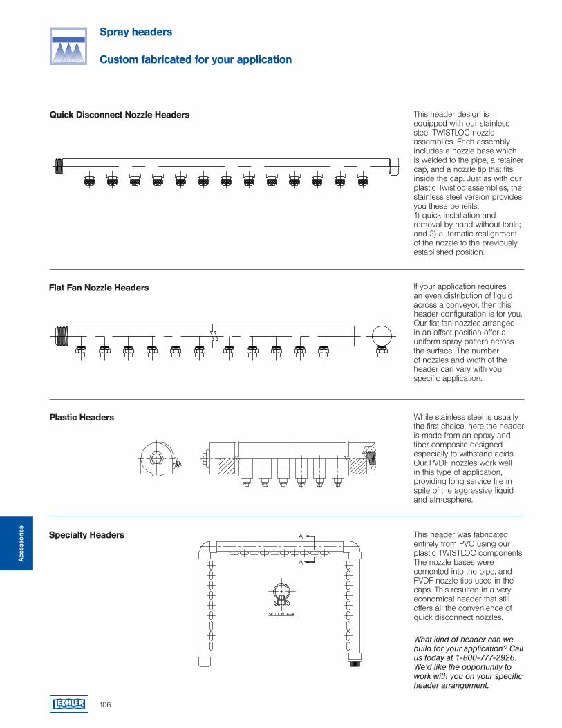
106
Spray headers
Custom fabricated for your application
This header design is equipped with our stainless steel TWISTLOC nozzle assemblies. Each assembly includes a nozzle base which is welded to the pipe, a retainer cap, and a nozzle tip that fits inside the cap. Just as with our plastic Twistloc assemblies, the stainless steel version provides you these benefits: 1) quick installation and removal by hand without tools; and 2) automatic realignment of the nozzle to the previously established position.
If your application requires an even distribution of liquid across a conveyor, then this header configuration is for you. Our flat fan nozzles arranged in an offset position offer a uniform spray pattern across the surface. The number of nozzles and width of the header can vary with your specific application.
While stainless steel is usually the first choice, here the header is made from an epoxy and fiber composite designed especially to withstand acids. Our PVDF nozzles work well in this type of application, providing long service life in spite of the aggressive liquid and atmosphere.
This header was fabricated entirely from PVC using our plastic TWISTLOC components. The nozzle bases were cemented into the pipe, and PVDF nozzle tips used in the caps. This resulted in a very economical header that still offers all the convenience of quick disconnect nozzles.
What kind of header can we build for your application? Call us today at 1-800-777-2926. We’d like the opportunity to work with you on your specific header arrangement.
Quick Disconnect Nozzle Headers
Flat Fan Nozzle Headers
Plastic Headers
Specialty Headers
Acc
esso
ries
Pulp and paperEdge trimmingFelt and wire cleaningWeb moisteningCoatingKnock off sprayPressure cleaningBleaching and brown stock washingLubricationSuction roll cleaningHead box cleaningand many others...
108
Nozzles and engineered systems for quality pulp and paper production
Lechler has been involved with paper manufacturing since the earliest periods of its history. The experience we have developed over that time, working with the world’s finest companies, puts us in a unique position today to serve the pulp and paper producers of North America.
Our skills as nozzle engineers, combined with our long partnership with Heinrich Stamm GmbH gives us a very broad product offering for this industry. The traditions of both companies for engineering creativity, manufacturing quality and operational durability are built into every nozzle, shower and oscillator.
Section contents: Page:
Trimming nozzles 110
High pressure solid stream nozzles 113
Self-cleaning showers 115
Shower nozzles 116
Linear oscillators 118
Pulp
and
Pap
er
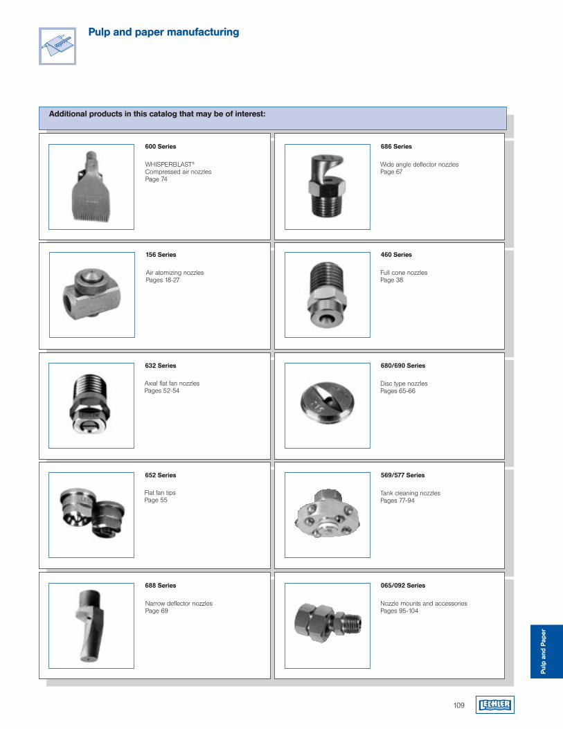
109
Pulp and paper manufacturing
Additional products in this catalog that may be of interest:
600 Series
WHISPERBLAST® Compressed air nozzlesPage 74
1/4" BSPP Spray cleaning with header mounting. Excellent for tight clearance installation.
156 Series
686 Series
Wide angle deflector nozzlesPage 67
460 Series
Full cone nozzlesPage 38
Air atomizing nozzlesPages 18-27
652 Series 569/577 Series
Tank cleaning nozzlesPages 77-94
632 Series 680/690 Series
Disc type nozzlesPages 65-66
Axial flat fan nozzlesPages 52-54
Flat fan tipsPage 55
688 Series
Narrow deflector nozzlesPage 69
065/092 Series
Nozzle mounts and accessoriesPages 95-104
Pulp
and
Pap
er
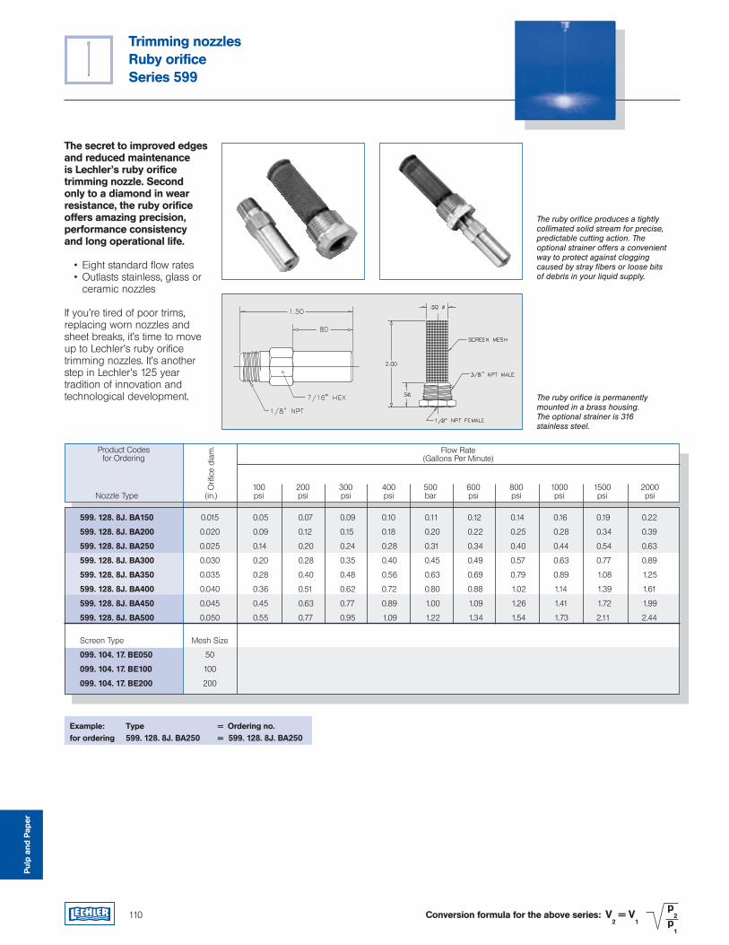
Trimming nozzlesRuby orificeSeries 599
Pulp
and
Pap
er
110
The secret to improved edges and reduced maintenance is Lechler’s ruby orifice trimming nozzle. Second only to a diamond in wear resistance, the ruby orifice offers amazing precision, performance consistency and long operational life.
• Eight standard flow rates • Outlasts stainless, glass or ceramic nozzles
If you’re tired of poor trims, replacing worn nozzles and sheet breaks, it’s time to move up to Lechler’s ruby orifice trimming nozzles. It’s another step in Lechler’s 125 year tradition of innovation and technological development.
The ruby orifice produces a tightly collimated solid stream for precise, predictable cutting action. The optional strainer offers a convenient way to protect against clogging caused by stray fibers or loose bits of debris in your liquid supply.
The ruby orifice is permanently mounted in a brass housing. The optional strainer is 316 stainless steel.
Product Codesfor Ordering
Flow Rate(Gallons Per Minute)
Orif
ice
diam
.
599. 128. 8J. BA150 0.015 0.05 0.07 0.09 0.10 0.11 0.12 0.14 0.16 0.19 0.22
599. 128. 8J. BA200 0.020 0.09 0.12 0.15 0.18 0.20 0.22 0.25 0.28 0.34 0.39
599. 128. 8J. BA250 0.025 0.14 0.20 0.24 0.28 0.31 0.34 0.40 0.44 0.54 0.63
599. 128. 8J. BA300 0.030 0.20 0.28 0.35 0.40 0.45 0.49 0.57 0.63 0.77 0.89
599. 128. 8J. BA350 0.035 0.28 0.40 0.48 0.56 0.63 0.69 0.79 0.89 1.08 1.25
599. 128. 8J. BA400 0.040 0.36 0.51 0.62 0.72 0.80 0.88 1.02 1.14 1.39 1.61
599. 128. 8J. BA450 0.045 0.45 0.63 0.77 0.89 1.00 1.09 1.26 1.41 1.72 1.99
599. 128. 8J. BA500 0.050 0.55 0.77 0.95 1.09 1.22 1.34 1.54 1.73 2.11 2.44
Screen Type Mesh Size
099. 104. 17. BE050 50
099. 104. 17. BE100 100
099. 104. 17. BE200 200
100 200 300 400 500 600 800 1000 1500 2000 Nozzle Type (in.) psi psi psi psi bar psi psi psi psi psi
Example: Type = Ordering no.for ordering 599. 128. 8J. BA250 = 599. 128. 8J. BA250
V2 = V
1
p2
p1
Conversion formula for the above series:
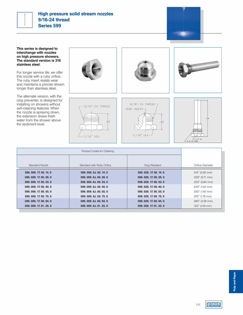
111
High pressure solid stream nozzles9/16-24 threadSeries 599
Pulp
and
Pap
er
This series is designed to interchange with nozzles on high pressure showers. The standard version is 316 stainless steel.
For longer service life, we offer this nozzle with a ruby orifice. The ruby insert resists wear and maintains a precise stream longer than stainless steel.
The alternate version, with the clog preventer, is designed for installing on showers without self-cleaning features. When the nozzle is spraying down, the extension draws fresh water from the shower above the sediment level.
Product Codes for Ordering
Standard Nozzle Standard with Ruby Orifice Clog Resistant Orifice Diameter
599. 009. 17. 00. 14. 0 599. 009. 8J. 00. 14. 0 599. 028. 17. 00. 14. 0 .014" (0.36 mm)
599. 009. 17. 00. 28. 0 599. 009. 8J. 00. 28. 0 599. 028. 17. 00. 28. 0 .028" (0.71 mm)
599. 009. 17. 00. 33. 0 599. 009. 8J. 00. 33. 0 599. 028. 17. 00. 33. 0 .033" (0.84 mm)
599. 009. 17. 00. 40. 0 599. 009. 8J. 00. 40. 0 599. 028. 17. 00. 40. 0 .040" (1.02 mm)
599. 009. 17. 00. 55. 0 599. 009. 8J. 00. 55. 0 599. 028. 17. 00. 55. 0 .055" (1.40 mm)
599. 009. 17. 00. 70. 0 599. 009. 8J. 00. 70. 0 599. 028. 17. 00. 70. 0 .070" (1.78 mm)
599. 009. 17. 00. 94. 0 599. 009. 8J. 00. 94. 0 599. 028. 17. 00. 94. 0 .094" (2.39 mm)
599. 009. 17. 01. 25. 0 599. 009. 8J. 01. 25. 0 599. 028. 17. 01. 25. 0 .125" (3.18 mm)
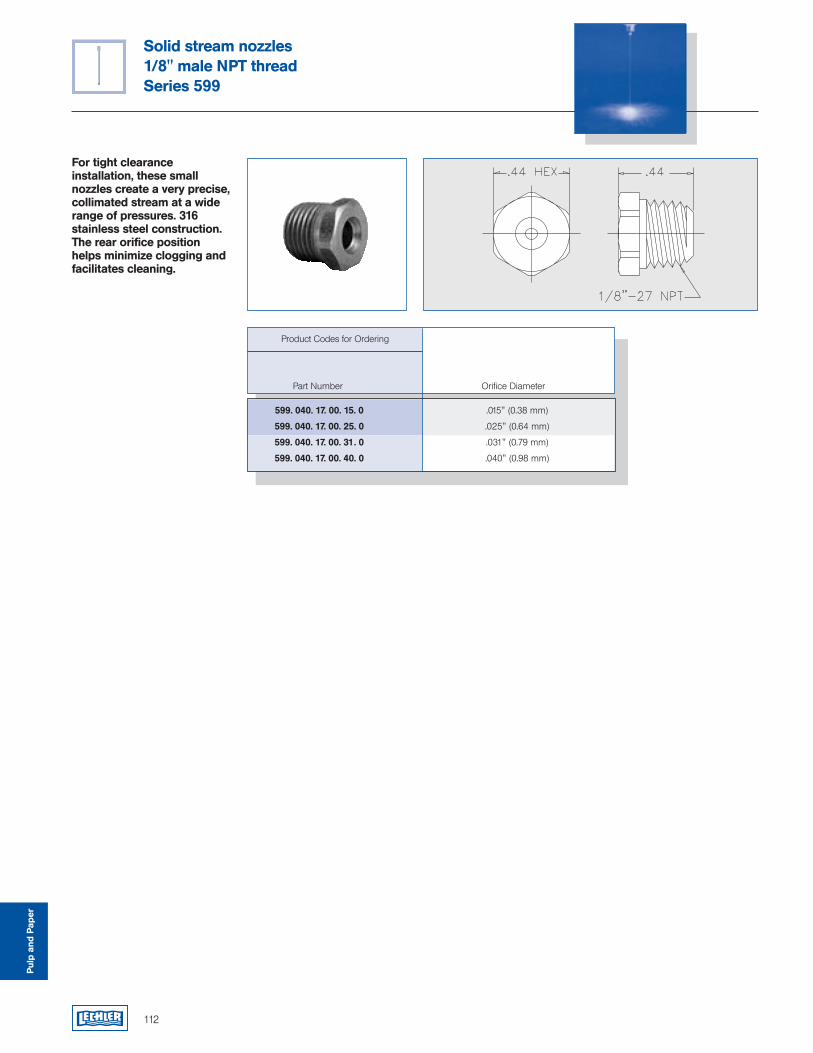
112
Solid stream nozzles1/8" male NPT threadSeries 599
For tight clearance installation, these small nozzles create a very precise, collimated stream at a wide range of pressures. 316 stainless steel construction.The rear orifice position helps minimize clogging and facilitates cleaning.
Pulp
and
Pap
er
Product Codes for Ordering
Part Number Orifice Diameter
599. 040. 17. 00. 15. 0 .015" (0.38 mm)
599. 040. 17. 00. 25. 0 .025" (0.64 mm)
599. 040. 17. 00. 31. 0 .031" (0.79 mm)
599. 040. 17. 00. 40. 0 .040" (0.98 mm)
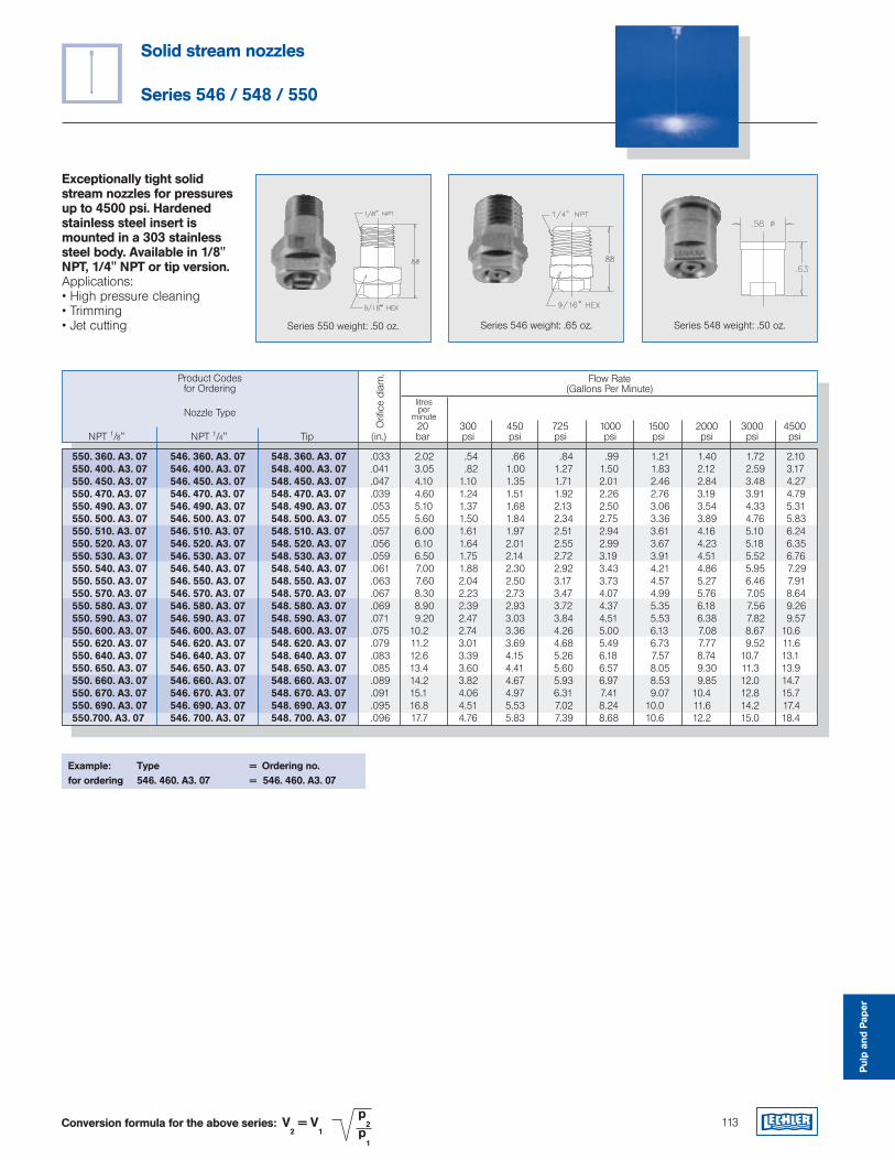
113
Solid stream nozzles
Series 546 / 548 / 550
Exceptionally tight solid stream nozzles for pressures up to 4500 psi. Hardened stainless steel insert is mounted in a 303 stainless steel body. Available in 1/8" NPT, 1/4" NPT or tip version.Applications:• High pressure cleaning• Trimming • Jet cutting
550. 360. A3. 07 546. 360. A3. 07 548. 360. A3. 07 .033 2.02 .54 .66 .84 .99 1.21 1.40 1.72 2.10 550. 400. A3. 07 546. 400. A3. 07 548. 400. A3. 07 .041 3.05 .82 1.00 1.27 1.50 1.83 2.12 2.59 3.17 550. 450. A3. 07 546. 450. A3. 07 548. 450. A3. 07 .047 4.10 1.10 1.35 1.71 2.01 2.46 2.84 3.48 4.27 550. 470. A3. 07 546. 470. A3. 07 548. 470. A3. 07 .039 4.60 1.24 1.51 1.92 2.26 2.76 3.19 3.91 4.79 550. 490. A3. 07 546. 490. A3. 07 548. 490. A3. 07 .053 5.10 1.37 1.68 2.13 2.50 3.06 3.54 4.33 5.31 550. 500. A3. 07 546. 500. A3. 07 548. 500. A3. 07 .055 5.60 1.50 1.84 2.34 2.75 3.36 3.89 4.76 5.83 550. 510. A3. 07 546. 510. A3. 07 548. 510. A3. 07 .057 6.00 1.61 1.97 2.51 2.94 3.61 4.16 5.10 6.24 550. 520. A3. 07 546. 520. A3. 07 548. 520. A3. 07 .056 6.10 1.64 2.01 2.55 2.99 3.67 4.23 5.18 6.35 550. 530. A3. 07 546. 530. A3. 07 548. 530. A3. 07 .059 6.50 1.75 2.14 2.72 3.19 3.91 4.51 5.52 6.76 550. 540. A3. 07 546. 540. A3. 07 548. 540. A3. 07 .061 7.00 1.88 2.30 2.92 3.43 4.21 4.86 5.95 7.29 550. 550. A3. 07 546. 550. A3. 07 548. 550. A3. 07 .063 7.60 2.04 2.50 3.17 3.73 4.57 5.27 6.46 7.91 550. 570. A3. 07 546. 570. A3. 07 548. 570. A3. 07 .067 8.30 2.23 2.73 3.47 4.07 4.99 5.76 7.05 8.64 550. 580. A3. 07 546. 580. A3. 07 548. 580. A3. 07 .069 8.90 2.39 2.93 3.72 4.37 5.35 6.18 7.56 9.26 550. 590. A3. 07 546. 590. A3. 07 548. 590. A3. 07 .071 9.20 2.47 3.03 3.84 4.51 5.53 6.38 7.82 9.57 550. 600. A3. 07 546. 600. A3. 07 548. 600. A3. 07 .075 10.2 2.74 3.36 4.26 5.00 6.13 7.08 8.67 10.6 550. 620. A3. 07 546. 620. A3. 07 548. 620. A3. 07 .079 11.2 3.01 3.69 4.68 5.49 6.73 7.77 9.52 11.6 550. 640. A3. 07 546. 640. A3. 07 548. 640. A3. 07 .083 12.6 3.39 4.15 5.26 6.18 7.57 8.74 10.7 13.1 550. 650. A3. 07 546. 650. A3. 07 548. 650. A3. 07 .085 13.4 3.60 4.41 5.60 6.57 8.05 9.30 11.3 13.9 550. 660. A3. 07 546. 660. A3. 07 548. 660. A3. 07 .089 14.2 3.82 4.67 5.93 6.97 8.53 9.85 12.0 14.7 550. 670. A3. 07 546. 670. A3. 07 548. 670. A3. 07 .091 15.1 4.06 4.97 6.31 7.41 9.07 10.4 12.8 15.7 550. 690. A3. 07 546. 690. A3. 07 548. 690. A3. 07 .095 16.8 4.51 5.53 7.02 8.24 10.0 11.6 14.2 17.4 550.700. A3. 07 546. 700. A3. 07 548. 700. A3. 07 .096 17.7 4.76 5.83 7.39 8.68 10.6 12.2 15.0 18.4
Example: Type = Ordering no.for ordering 546. 460. A3. 07 = 546. 460. A3. 07
Product Codesfor Ordering
Flow Rate(Gallons Per Minute)
20 300 450 725 1000 1500 2000 3000 4500 NPT 1/8" NPT 1/4" Tip (in.) bar psi psi psi psi psi psi psi psi
litresper
minuteNozzle Type
Orif
ice
diam
.
Series 550 weight: .50 oz. Series 546 weight: .65 oz. Series 548 weight: .50 oz.
V2 = V
1
p2
p1
Conversion formula for the above series:
Pulp
and
Pap
er
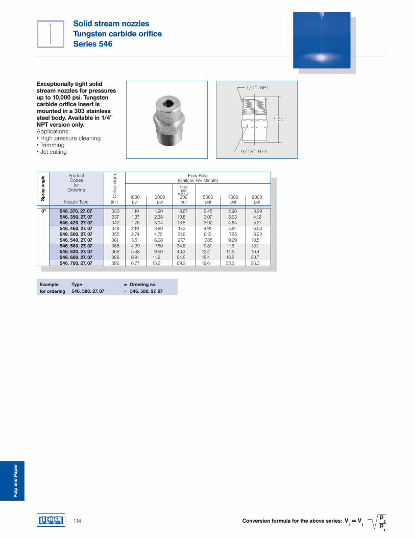
114
Solid stream nozzlesTungsten carbide orificeSeries 546
Exceptionally tight solid stream nozzles for pressures up to 10,000 psi. Tungsten carbide orifice insert is mounted in a 303 stainless steel body. Available in 1/4" NPT version only.Applications:• High pressure cleaning• Trimming • Jet cutting
ProductCodes
for Ordering
Flow Rate(Gallons Per Minute)litresper
minute
Orif
ice
diam
.
Spr
ay a
ngle
1000 3000 300 5000 7000 9000 Nozzle Type (in.) psi psi bar psi psi psi
0° 546. 370. 27. 07 .033 1.10 1.90 8.67 2.45 2.90 3.29 546. 390. 27. 07 .037 1.37 2.38 10.8 3.07 3.63 4.12 546. 420. 27. 07 .042 1.76 3.04 13.8 3.92 4.64 5.27 546. 460. 27. 07 .049 2.19 3.80 17.3 4.91 5.81 6.58 546. 500. 27. 07 .055 2.74 4.75 21.6 6.13 7.25 8.22 546. 540. 27. 07 .061 3.51 6.08 27.7 7.85 9.29 10.5 546. 580. 27. 07 .068 4.39 7.60 34.6 9.81 11.6 13.1 546. 620. 27. 07 .068 5.48 9.50 43.3 12.2 14.5 16.4 546. 660. 27. 07 .086 6.91 11.9 54.5 15.4 18.2 20.7 546. 700. 27. 07 .096 8.77 15.2 69.2 19.6 23.2 26.3
Pulp
and
Pap
er
V2 = V
1
p2
p1
Conversion formula for the above series:
Example: Type = Ordering no.for ordering 546. 580. 27. 07 = 546. 580. 27. 07
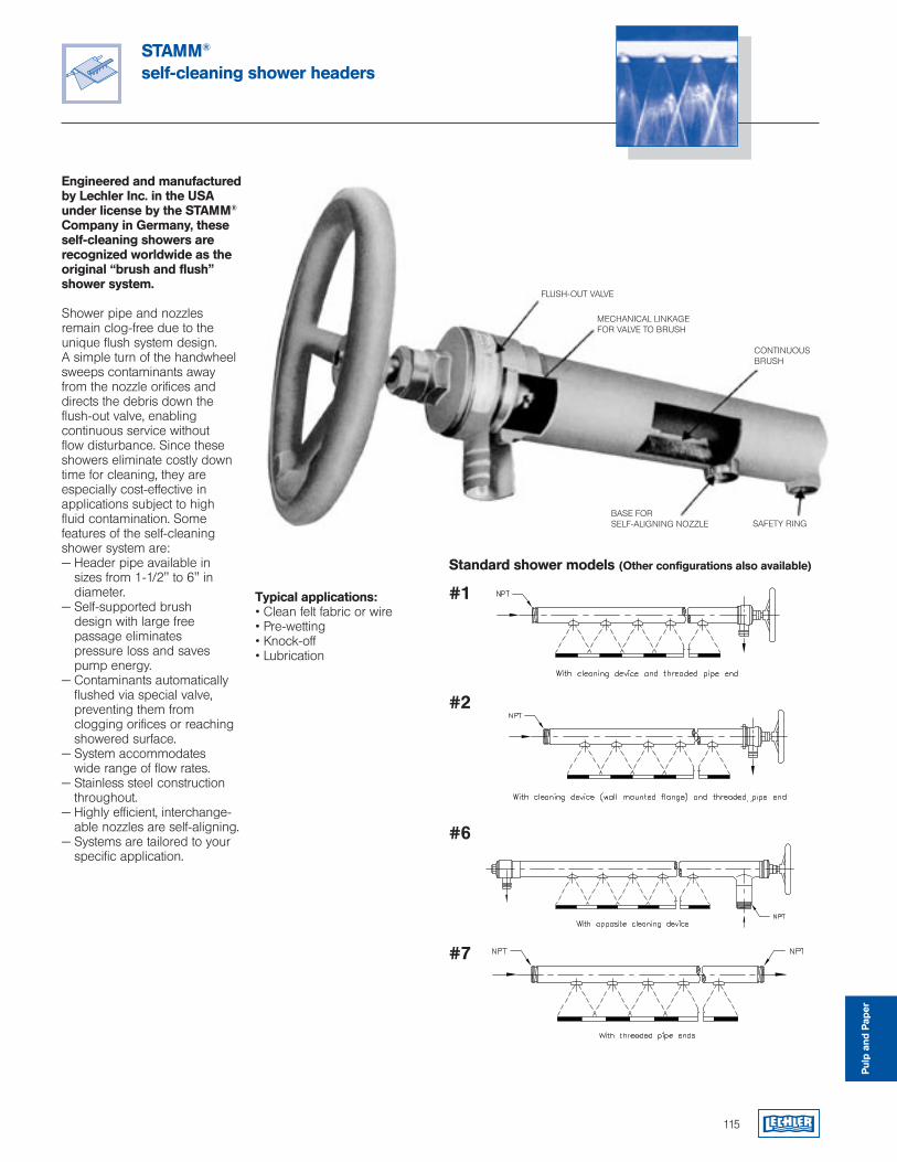
115
STAMM® self-cleaning shower headers
Engineered and manufactured by Lechler Inc. in the USA under license by the STAMM® Company in Germany, these self-cleaning showers are recognized worldwide as the original “brush and flush” shower system.
Shower pipe and nozzles remain clog-free due to the unique flush system design. A simple turn of the handwheel sweeps contaminants away from the nozzle orifices and directs the debris down the flush-out valve, enabling continuous service without flow disturbance. Since these showers eliminate costly down time for cleaning, they are especially cost-effective in applications subject to high fluid contamination. Some features of the self-cleaning shower system are:— Header pipe available in
sizes from 1-1/2" to 6" in diameter.
— Self-supported brush design with large free passage eliminates pressure loss and saves pump energy.
— Contaminants automatically flushed via special valve, preventing them from clogging orifices or reaching showered surface.
— System accommodates wide range of flow rates.
— Stainless steel construction throughout.
— Highly efficient, interchange- able nozzles are self-aligning.
— Systems are tailored to your specific application.
#1
#2
#6
#7
Standard shower models (Other configurations also available)
FLUSH-OUT VALVE
MECHANICAL LINKAGEFOR VALVE TO BRUSH
CONTINUOUS BRUSH
BASE FORSELF-ALIGNING NOZZLE SAFETY RING
Typical applications:• Clean felt fabric or wire• Pre-wetting• Knock-off• Lubrication
Pulp
and
Pap
er
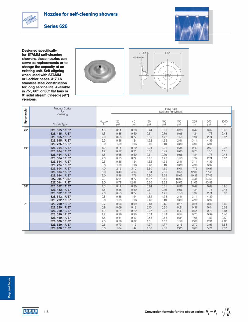
116
Nozzles for self-cleaning showers
Series 626
V2 = V
1
p2
p1
Conversion formula for the above series:
Designed specifically for STAMM self-cleaning showers, these nozzles can serve as replacements or to change the capacity of an existing unit. Self aligning when used with STAMM or Lechler bases. 317 LN stainless steel construction for long service life. Available in 75o, 60o, or 30o flat fans or 0o solid stream (“needle jet”) versions.
Pulp
and
Pap
er
Product Codesfor
Ordering
Flow Rate(Gallons Per Minute)
Spr
ay a
ngle
Nozzle 20 40 60 100 150 250 500 1000 Nozzle Type # psi psi psi psi psi psi psi psi
75o 626. 365. 1F. 37 1.0 0.14 0.20 0.24 0.31 0.38 0.49 0.69 0.98 626. 485. 1F. 37 1.5 0.35 0.50 0.61 0.79 0.96 1.24 1.76 2.48 626. 565. 1F. 37 2.0 0.55 0.77 0.95 1.22 1.50 1.94 2.74 3.87 626. 645. 1F. 37 2.5 0.88 1.24 1.52 1.96 2.41 3.11 4.39 626. 725. 1F. 37 3.0 1.39 1.96 2.40 3.10 3.80 4.90 6.94 60o 626. 364. 1F. 37 1.0 0.14 0.20 0.24 0.31 0.38 0.49 0.69 0.98 626. 404. 1F. 37 1.2 0.22 0.31 0.38 0.49 0.60 0.78 1.10 1.55 626. 464. 1F. 37 1.5 0.35 0.50 0.61 0.79 0.96 1.24 1.76 2.48 626. 564. 1F. 37 2.0 0.55 0.77 0.95 1.22 1.50 1.94 2.74 3.87 626. 644. 1F. 37 2.5 0.88 1.24 1.52 1.96 2.41 3.11 4.39 626. 724. 1F. 37 3.0 1.39 1.96 2.40 3.10 3.80 4.90 6.94 626. 804. 1F. 37 4.0 2.19 3.10 3.80 4.90 6.01 7.75 10.97 626. 884. 1F. 37 5.0 3.49 4.94 6.04 7.80 9.56 12.34 17.45 626. 964. 1F. 37 6.0 5.48 7.76 9.50 12.26 15.02 19.39 27.42 627. 004. 1F. 37 7.0 6.91 9.77 11.97 15.46 18.93 24.44 34.56 627. 044. 1F. 37 8.0 8.78 12.41 15.20 19.62 24.03 31.03 43.88 30o 626. 362. 1F. 37 1.0 0.14 0.20 0.24 0.31 0.38 0.49 0.69 0.98 626. 482. 1F. 37 1.5 0.35 0.50 0.61 0.79 0.96 1.24 1.76 2.48 626. 562. 1F. 37 2.0 0.55 0.77 0.95 1.22 1.50 1.94 2.74 3.87 626. 642. 1F. 37 2.5 0.88 1.24 1.52 1.96 2.41 3.11 4.39 626. 722. 1F. 37 3.0 1.39 1.96 2.40 3.10 3.80 4.90 6.94 0o 626. 290. 1F. 37 0.7 0.06 0.09 0.10 0.14 0.17 0.21 0.30 0.43 626. 320. 1F. 37 0.8 0.09 0.13 0.15 0.20 0.24 0.31 0.44 0.63 626. 360. 1F. 37 1.0 0.16 0.22 0.27 0.35 0.43 0.55 0.78 1.10 626. 390. 1F. 37 1.2 0.20 0.28 0.34 0.44 0.54 0.70 0.99 1.40 626. 460. 1F. 37 1.5 0.31 0.43 0.53 0.68 0.84 1.08 1.53 2.17 626. 570. 1F. 37 2.0 0.58 0.82 1.01 1.30 1.59 2.06 2.91 4.12 626. 620. 1F. 37 2.5 0.79 1.12 1.37 1.77 2.16 2.79 3.95 5.58 626. 670. 1F. 37 3.0 1.04 1.47 1.80 2.33 2.85 3.68 5.21 7.37
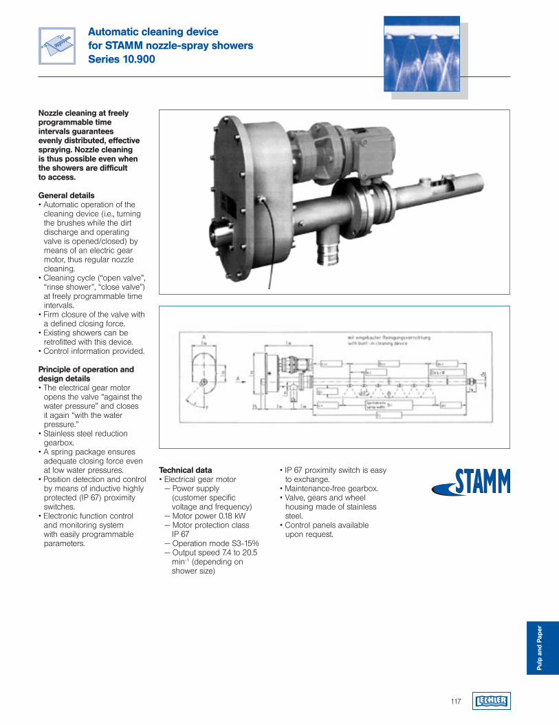
117
Automatic cleaning devicefor STAMM nozzle-spray showersSeries 10.900
Nozzle cleaning at freely programmable time intervals guarantees evenly distributed, effective spraying. Nozzle cleaning is thus possible even when the showers are difficult to access.
General details• Automatic operation of the
cleaning device (i.e., turning the brushes while the dirt discharge and operating valve is opened/closed) by means of an electric gear motor, thus regular nozzle cleaning.
• Cleaning cycle (“open valve”, “rinse shower”, “close valve”) at freely programmable time intervals.
• Firm closure of the valve with a defined closing force.
• Existing showers can be retrofitted with this device.
• Control information provided.
Principle of operation and design details• The electrical gear motor
opens the valve “against the water pressure” and closes it again “with the water pressure.”
• Stainless steel reduction gearbox.
• A spring package ensures adequate closing force even at low water pressures.
• Position detection and control by means of inductive highly protected (IP 67) proximity switches.
• Electronic function control and monitoring system with easily programmable parameters.
Technical data• Electrical gear motor — Power supply
(customer specific voltage and frequency) — Motor power 0.18 kW — Motor protection class IP 67 — Operation mode S3-15% — Output speed 7.4 to 20.5
min-1 (depending on shower size)
• IP 67 proximity switch is easy to exchange.
• Maintenance-free gearbox.• Valve, gears and wheel
housing made of stainless steel.
• Control panels available upon request.
Pulp
and
Pap
er
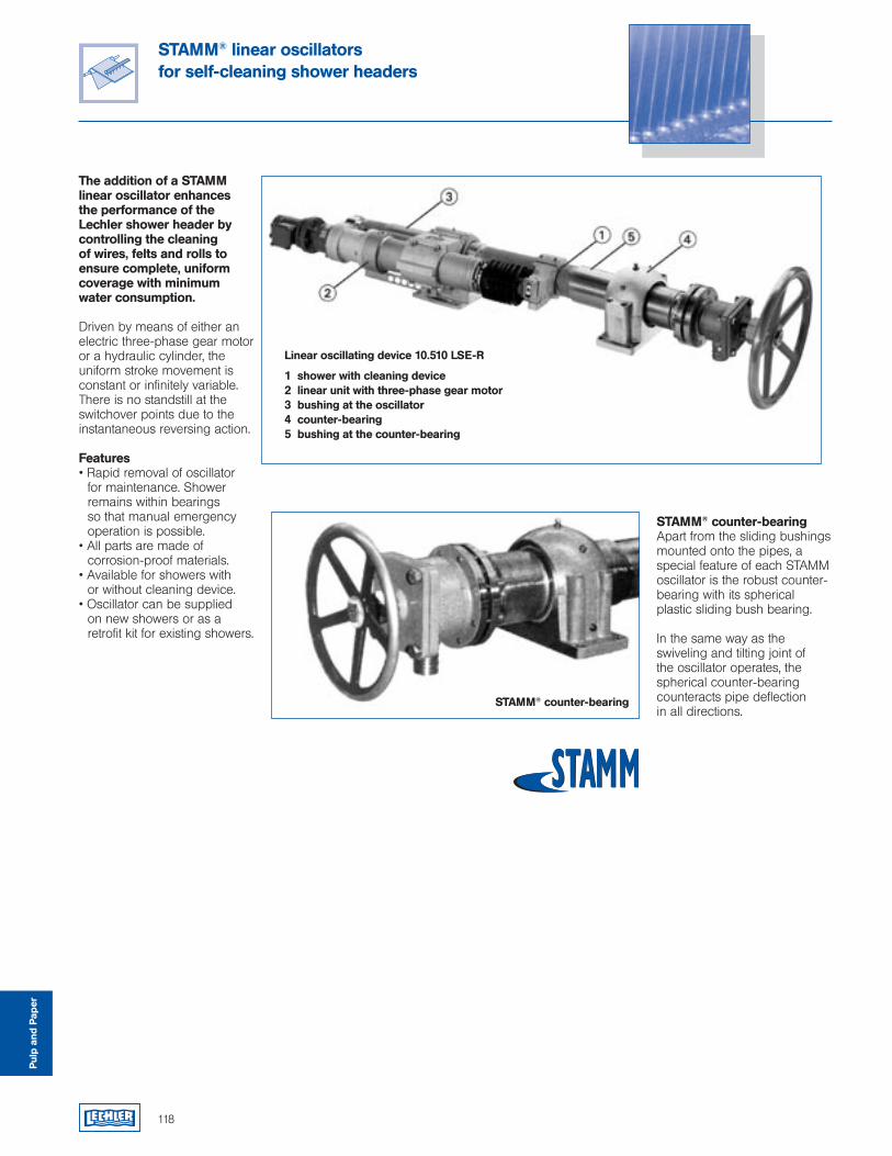
118
STAMM® linear oscillators for self-cleaning shower headers
The addition of a STAMM linear oscillator enhances the performance of the Lechler shower header by controlling the cleaning of wires, felts and rolls to ensure complete, uniform coverage with minimum water consumption.
Driven by means of either an electric three-phase gear motor or a hydraulic cylinder, the uniform stroke movement is constant or infinitely variable. There is no standstill at the switchover points due to the instantaneous reversing action.
Features• Rapid removal of oscillator
for maintenance. Shower remains within bearings so that manual emergency operation is possible.
• All parts are made of corrosion-proof materials.
• Available for showers with or without cleaning device.
• Oscillator can be supplied on new showers or as a retrofit kit for existing showers.
Linear oscillating device 10.510 LSE-R
1 shower with cleaning device2 linear unit with three-phase gear motor3 bushing at the oscillator4 counter-bearing5 bushing at the counter-bearing
STAMM® counter-bearing
STAMM® counter-bearingApart from the sliding bushings mounted onto the pipes, a special feature of each STAMM oscillator is the robust counter-bearing with its spherical plastic sliding bush bearing.
In the same way as the swiveling and tilting joint of the oscillator operates, the spherical counter-bearing counteracts pipe deflection in all directions.
Pulp
and
Pap
er
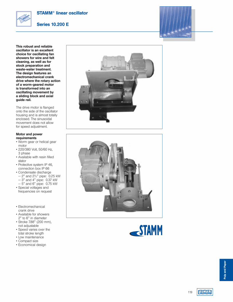
119
STAMM® linear oscillator
Series 10.200 E
This robust and reliable oscillator is an excellent choice for oscillating fan showers for wire and felt cleaning, as well as for stock preparation and waste-water treatment. The design features an electromechanical crank drive where the rotary action of a worm-geared motor is transformed into an oscillating movement by a sliding block and axial guide rail.
The drive motor is flanged onto the side of the oscillator housing and is almost totally enclosed. The sinusoidal movement does not allow for speed adjustment.
Motor and power requirements• Worm gear or helical gear
motor• 220/380 Volt, 50/60 Hz,
3 phase• Available with resin filled
stator• Protective system IP 46,
connection box IP 66• Condensate discharge — 2" and 21/2" pipe: 0.25 kW — 3" and 4" pipe: 0.37 kW — 5" and 6" pipe: 0.75 kW• Special voltages and
frequencies on request
• Electromechanical crank drive
• Available for showers 2" to 6" in diameter
• Stroke 7.88" (200 mm), not adjustable
• Speed varies over the total stroke length
• Low maintenance• Compact size• Economical design
Pulp
and
Pap
er
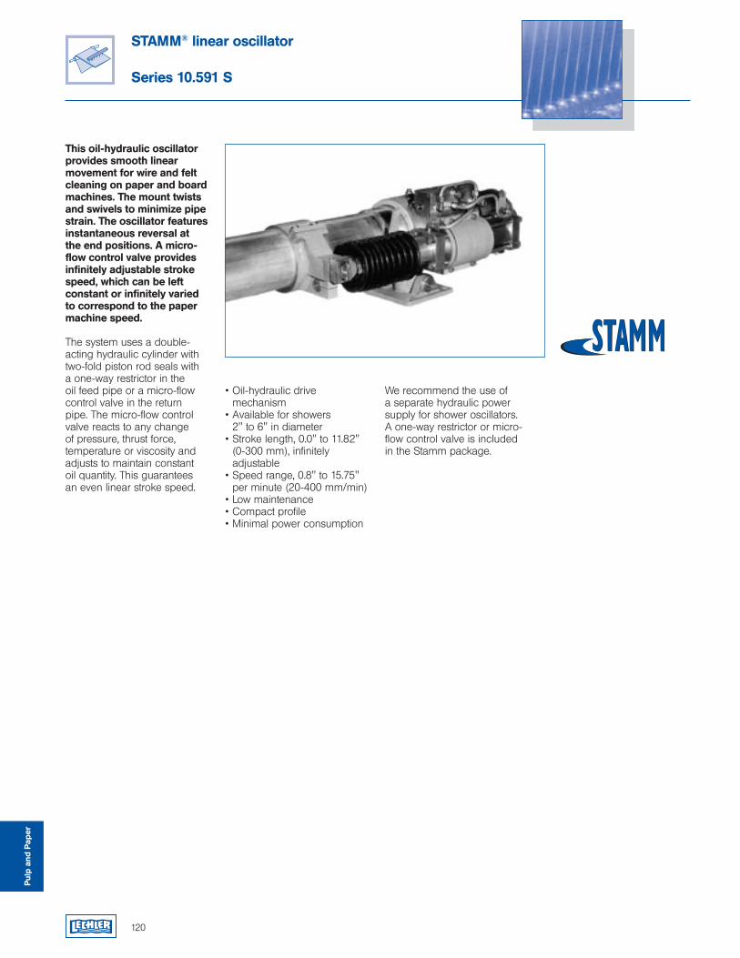
120
STAMM® linear oscillator
Series 10.591 S
This oil-hydraulic oscillator provides smooth linear movement for wire and felt cleaning on paper and board machines. The mount twists and swivels to minimize pipe strain. The oscillator features instantaneous reversal at the end positions. A micro-flow control valve provides infinitely adjustable stroke speed, which can be left constant or infinitely varied to correspond to the paper machine speed.
The system uses a double-acting hydraulic cylinder with two-fold piston rod seals with a one-way restrictor in the oil feed pipe or a micro-flow control valve in the return pipe. The micro-flow control valve reacts to any change of pressure, thrust force, temperature or viscosity and adjusts to maintain constant oil quantity. This guarantees an even linear stroke speed.
• Oil-hydraulic drive mechanism
• Available for showers 2" to 6" in diameter
• Stroke length, 0.0" to 11.82" (0-300 mm), infinitely adjustable
• Speed range, 0.8" to 15.75" per minute (20-400 mm/min)
• Low maintenance• Compact profile• Minimal power consumption
We recommend the use of a separate hydraulic power supply for shower oscillators. A one-way restrictor or micro-flow control valve is included in the Stamm package.
Pulp
and
Pap
er
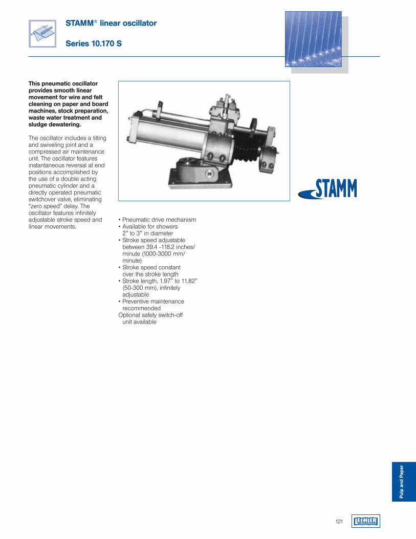
STAMM® linear oscillator
Series 10.170 S
This pneumatic oscillator provides smooth linear movement for wire and felt cleaning on paper and board machines, stock preparation, waste water treatment and sludge dewatering.
The oscillator includes a tilting and swiveling joint and a compressed air maintenance unit. The oscillator features instantaneous reversal at end positions accomplished by the use of a double acting pneumatic cylinder and a directly operated pneumatic switchover valve, eliminating “zero speed” delay. The oscillator features infinitely adjustable stroke speed and linear movements.
• Pneumatic drive mechanism• Available for showers
2" to 3" in diameter• Stroke speed adjustable
between 39.4 -118.2 inches/minute (1000-3000 mm/minute)
• Stroke speed constant over the stroke length
• Stroke length, 1.97" to 11.82" (50-300 mm), infinitely adjustable
• Preventive maintenance recommended
Optional safety switch-off unit available
121
Pulp
and
Pap
er
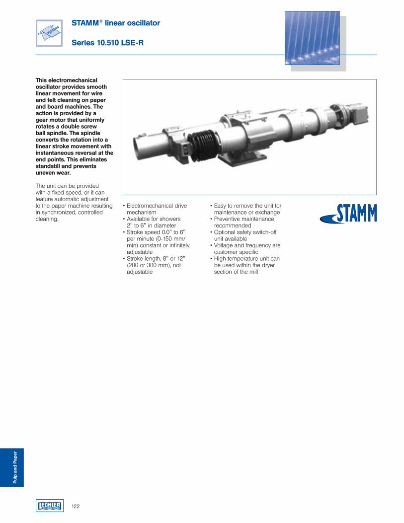
122
STAMM® linear oscillator
Series 10.510 LSE-R
This electromechanical oscillator provides smooth linear movement for wire and felt cleaning on paper and board machines. The action is provided by a gear motor that uniformly rotates a double screw ball spindle. The spindle converts the rotation into a linear stroke movement with instantaneous reversal at the end points. This eliminates standstill and prevents uneven wear.
The unit can be provided with a fixed speed, or it can feature automatic adjustment to the paper machine resulting in synchronized, controlled cleaning.
• Electromechanical drive mechanism
• Available for showers 2" to 6" in diameter
• Stroke speed 0.0" to 6" per minute (0-150 mm/min) constant or infinitely adjustable
• Stroke length, 8" or 12" (200 or 300 mm), not adjustable
• Easy to remove the unit for maintenance or exchange
• Preventive maintenance recommended
• Optional safety switch-off unit available
• Voltage and frequency are customer specific
• High temperature unit can be used within the dryer section of the mill
Pulp
and
Pap
er
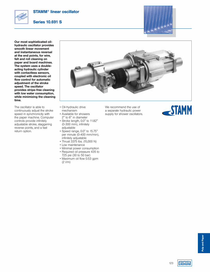
STAMM® linear oscillator
Series 10.691 S
Our most sophisticated oil-hydraulic oscillator provides smooth linear movement and instantaneous reversal at the end points, for wire, felt and roll cleaning on paper and board machines. The system uses a double-acting hydraulic cylinder with contactless sensors, coupled with electronic oil flow control for automatic adjustment of the stroke speed. The oscillator provides stripe-free cleaning with low water consumption, while minimizing the cleaning time.
The oscillator is able to continuously adjust the stroke speed in synchronicity with the paper machine. Computer controls provide infinitely adjustable stroke, staggering reverse points, and a fast return option.
• Oil-hydraulic drive mechanism
• Available for showers 2" to 6" in diameter
• Stroke length, 0.0" to 11.82" (0-300 mm), infinitely adjustable
• Speed range, 0.0" to 15.75" per minute (0-400 mm/min), infinitely adjustable
• Thrust 3375 lbs. (15,000 N)• Low maintenance• Minimal power consumption• Required oil pressure 435 to
725 psi (30 to 50 bar)• Maximum oil flow 0.53 gpm
(2 l/m)
We recommend the use of a separate hydraulic power supply for shower oscillators.
123
Pulp
and
Pap
er

124
STAMM® linear oscillator
Series 10.510 EC
Our most sophisticated electromechanical oscillator provides smooth linear movement synchronized with the machine speed for wire, felt and roll cleaning on paper and board machines. The system uses a stepper motor coupled to a planetary gear reducer to drive a ball screw spindle. The movement is governed by the paper machine speed.
Computer controls allow automatic adjustment of the stroke speed to the paper machine speed. Stroke length, reverse point staggering and fast return are controlled and monitored with simple programming via a supplied control panel.
• Electromechanical drive mechanism
• Available for showers 2" to 6" in diameter
• Stroke length, 0.040" to 11.82" (1-300 mm), infinitely adjustable
• Speed range, 0.0" to 15.75" per minute (0-400 mm/min), infinitely adjustable
• Thrust 2698 lbs. (12,000 N)• Compact profile• Fully sealed housing • Low maintenance• Minimal power consumption• Required electrical supply
24 VDC• Safety switch-off• Watertight stainless steel
housing (IP66)
Pulp
and
Pap
er
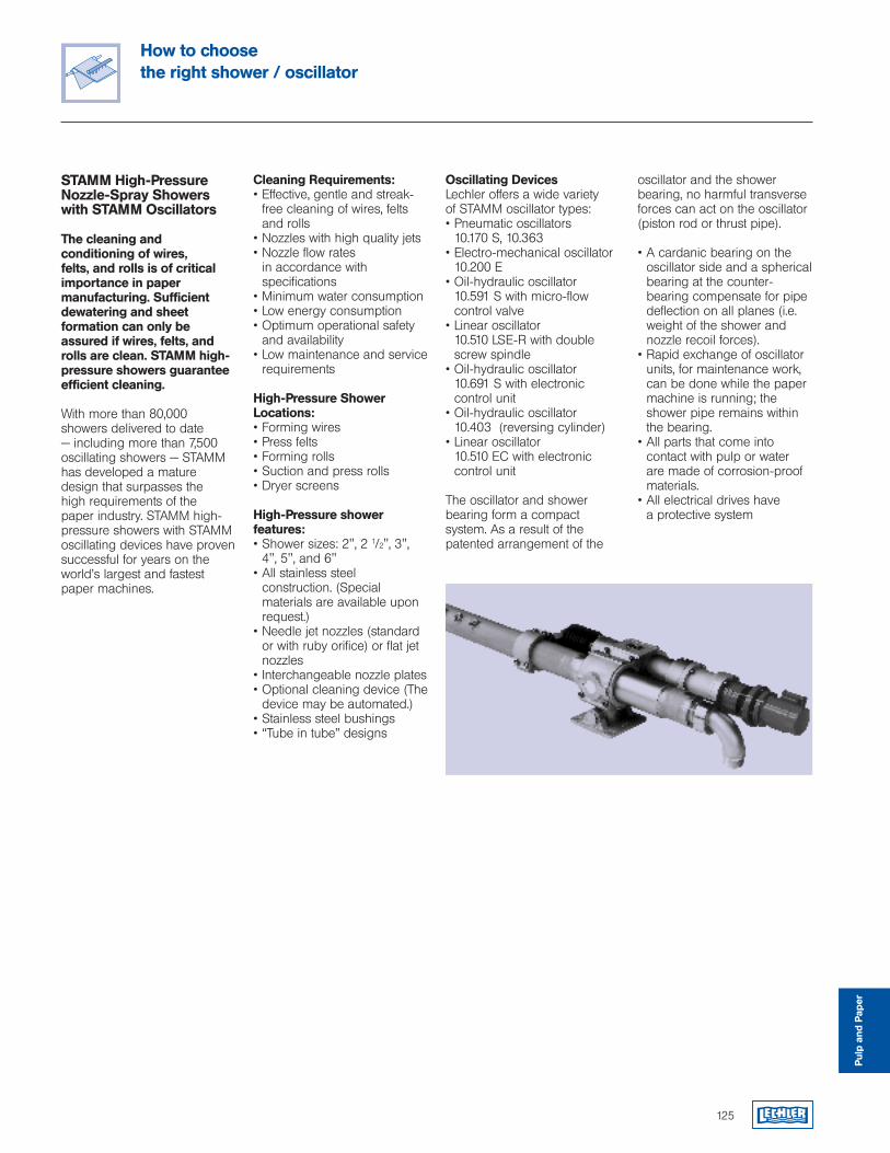
How to choose the right shower / oscillator
125
STAMM High-Pressure Nozzle-Spray Showers with STAMM Oscillators
The cleaning and conditioning of wires, felts, and rolls is of critical importance in paper manufacturing. Sufficient dewatering and sheet formation can only be assured if wires, felts, and rolls are clean. STAMM high-pressure showers guarantee efficient cleaning.
With more than 80,000 showers delivered to date — including more than 7,500 oscillating showers — STAMM has developed a mature design that surpasses the high requirements of the paper industry. STAMM high-pressure showers with STAMM oscillating devices have proven successful for years on the world’s largest and fastest paper machines.
Cleaning Requirements:• Effective, gentle and streak-
free cleaning of wires, felts and rolls
• Nozzles with high quality jets• Nozzle flow rates
in accordance with specifications
• Minimum water consumption• Low energy consumption • Optimum operational safety
and availability• Low maintenance and service
requirements
High-Pressure Shower Locations:• Forming wires• Press felts• Forming rolls• Suction and press rolls• Dryer screens
High-Pressure shower features:• Shower sizes: 2", 2 1/2", 3",
4", 5", and 6"• All stainless steel
construction. (Special materials are available upon request.)
• Needle jet nozzles (standard or with ruby orifice) or flat jet nozzles
• Interchangeable nozzle plates • Optional cleaning device (The
device may be automated.)• Stainless steel bushings• “Tube in tube” designs
oscillator and the shower bearing, no harmful transverse forces can act on the oscillator (piston rod or thrust pipe).
• A cardanic bearing on the oscillator side and a spherical bearing at the counter-bearing compensate for pipe deflection on all planes (i.e. weight of the shower and nozzle recoil forces).
• Rapid exchange of oscillator units, for maintenance work, can be done while the paper machine is running; the shower pipe remains within the bearing.
• All parts that come into contact with pulp or water are made of corrosion-proof materials.
• All electrical drives have a protective system
Oscillating DevicesLechler offers a wide variety of STAMM oscillator types:• Pneumatic oscillators
10.170 S, 10.363• Electro-mechanical oscillator
10.200 E• Oil-hydraulic oscillator
10.591 S with micro-flow control valve
• Linear oscillator 10.510 LSE-R with double
screw spindle• Oil-hydraulic oscillator
10.691 S with electronic control unit
• Oil-hydraulic oscillator 10.403 (reversing cylinder)
• Linear oscillator 10.510 EC with electronic control unit
The oscillator and shower bearing form a compact system. As a result of the patented arrangement of the
Pulp
and
Pap
er
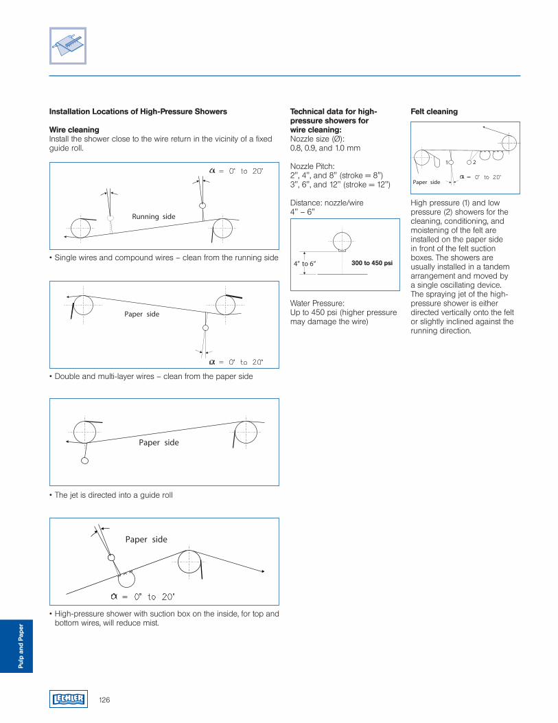
126
Installation Locations of High-Pressure Showers
Wire cleaningInstall the shower close to the wire return in the vicinity of a fixed guide roll.
• Single wires and compound wires – clean from the running side
• Double and multi-layer wires – clean from the paper side
• The jet is directed into a guide roll
• High-pressure shower with suction box on the inside, for top and bottom wires, will reduce mist.
Technical data for high-pressure showers for wire cleaning:Nozzle size (Ø): 0.8, 0.9, and 1.0 mm
Nozzle Pitch: 2", 4", and 8" (stroke = 8")3", 6", and 12" (stroke = 12")
Distance: nozzle/wire 4" – 6"
Water Pressure: Up to 450 psi (higher pressure may damage the wire)
Felt cleaning
High pressure (1) and low pressure (2) showers for the cleaning, conditioning, and moistening of the felt are installed on the paper side in front of the felt suction boxes. The showers are usually installed in a tandem arrangement and moved by a single oscillating device. The spraying jet of the high-pressure shower is either directed vertically onto the felt or slightly inclined against the running direction.
300 to 450 psi
Pulp
and
Pap
er

127
Technical data for high-pressure showers for felt cleaning:Nozzle size (Ø): 0.7, 0.8, 0.9, and 1.0 mm
Nozzle Pitch: 2", 4", and 8" (stroke = 8")3", 6", and 12" (stroke = 12")
Distance: nozzle/felt4" – 6"
Water Pressure:Up to 225 psi (higher pressure may damage the felt)
Roll cleaning
Because of difficult installation conditions in the vicinity of wire suction rolls, take-off suction rolls, suction press rolls and forming rolls, showers and oscillators should be designed to minimize space. STAMM high-pressure showers with guide pipe meet these requirements. Oscillation is achieved with an oil-hydraulic or pneumatic cylinder or a linear oscillator. The high-pressure shower oscillates inside a slotted guide pipe.
Technical data for high-pressure showers for roll cleaning:Nozzle size (Ø): 1.0 to 1.5 mm
Nozzle Pitch: 4", 8", and 20"
Distance: nozzle/felt 2" – 4"
Water Pressure: 450 psi – 1000 psi (maximum pressure 3000 psi)
Cleaning of dryer screensOscillating high-pressure showers are used for cleaning of dryer screens during production downtimes and cleaning intervals. “Jet to jet” cleaning ensures that the entire area is cleaned within a short period of time.
The shower is usually installed on the paper side, and the jet is directed against a guide roll, dryer screen suction roll, or drying cylinder. Oscillation is achieved with the linear oscillator 10.510 LSE-R, specifically designed for the high temperatures in the drying section.
Technical data for high-pressure showers for dryer screen cleaning:Nozzle size (Ø): 1.0 to 1.5 mm
Nozzle Pitch: 4", 8", 20"
Distance: nozzle/felt 2" – 4"
Water Pressure: 450 psi – 1000 psi (maximum pressure 3000 psi)
Cleaning principle of linear oscillators and oscillators with electronic control unit• Controlled “jet to jet” covering
the entire surface• Effective, gentle, and streak-
free cleaning of wires, felts and rolls
• Linear, smooth oscillation movement with instant reversal at the end positions
Calculation of oscillator speed VB according to formula
VS VB = _____ * eb LSF
VB = oscillator speed (in/min)
VS = machine speed (ft/min)
LSF = length of wire/felt (ft)
eb = width of cleaned strip (in)
Calculation of the cleaning time tR
A shower that operates in accordance with the above principle cleans the entire surface (wire, felt, roll) within a minimum period of time.
The cleaning time is calculated according to the formula:
LSF ktR = _____ * _____
VS eb
LSF = length of wire/felt (ft)
k = nozzle pitch (in)
VS = machine speed (ft/min)
eb = width of cleaned strip (in)
Pulp
and
Pap
er

128
Fill in, copy and send by fax: 630-377-6657 You’ll immediately receive detailed information.
Yes I want to know more !Send me the special information:
Tank cleaning nozzles
Precision nozzles for the food industry
Precision nozzles for the beverage industry
Precision nozzles for the automotive industry
Nozzles for compressed air
Nozzles for fire protection
VarioSpray® system for minute-volume
application
Ultrasonic atomizers
SCALEMASTER® HP “High Performance”
MiniSCALEMASTER®
SELECTOSPRAY® roll cooling system
Pollution control from Lechler
VarioCool® gas conditioning systems
Spillback nozzle lances for gas conditioning
Twinfluid nozzle lances for gas conditioning
Please call me My telephone number is:
We want to use nozzles from Lechler for the following application:
We belong to the following industry:
Our address
Name
Company/Department
Address
City/State/Zip
Telephone
Fax
Lechler has a wealth of specific product and process related literature and information. Much is available through our web site, but sometimes nothing can substitute for a handy brochure or catalog that you always keep nearby. Our material is very nuts and bolts oriented, with clear suggestions on how to optimize performance for specific applications.
The expertise in these brochures comes from the compiled knowledge of thousands of customer applications around the world. Each experience in the field advances our skill as a company and we pass that on to you in every discussion. This specialized literature works with the catalog to give you a detailed picture of the possibilities at your disposal. All you have to do is contact us and ask for help.
Getting the right information is a key step.
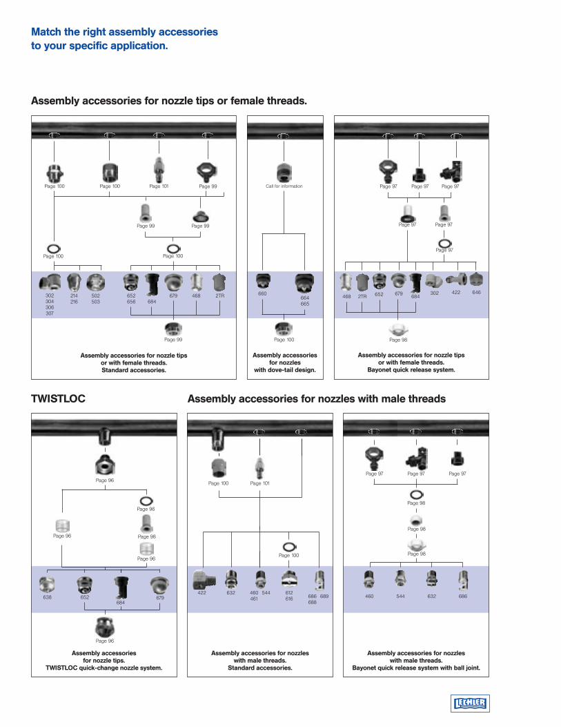
Assembly accessories for nozzle tips or female threads.
Assembly accessories for nozzles with male threadsTWISTLOC
Assembly accessories for nozzle tips or with female threads. Standard accessories.
Assembly accessories for nozzles
with dove-tail design.
Assembly accessories for nozzle tips or with female threads.
Bayonet quick release system.
Assembly accessories for nozzles with male threads.
Standard accessories.
Assembly accessories for nozzle tips.
TWISTLOC quick-change nozzle system.
Assembly accessories for nozzles with male threads.
Bayonet quick release system with ball joint.
Page 96
Page 96
Page 96
Page 96
Page 100 Page 100 Page 101 Page 99 Call for information
Page 99
Page 100Page 100
302304306307
214216
502503
652656 684
679
Page 99
660
Page 98
664665
Page 100
652 679 302 422
Page 97 Page 97Page 97
Page 97
Page 97
Page 97
652 679
Page 100 Page 101
422 632 460461
544 612616 686
688689
Page 100
Page 97 Page 97
Page 98
460 632 686
Page 98
Page 98
Page 97
684
Page 99
684
Page 96
Page 98
468 2TR 2TR646
638 544
468
Match the right assembly accessories to your specific application.

The Lechler web page is loaded with:
Product information
Specialized technical data
New product releases
Application helps
Trade show schedules
Links to our affiliates and subsidiaries
And more!
Log on and register today.
Visit our web sitewww.LechlerUSA.com
Lechler Inc.445 Kautz RoadSt. Charles, IL 60174Toll-free: 1-800-777-2926 Phone: (630) 377-6611Fax: (630) 377-6657
E-mail: [email protected]: www.LechlerUSA.com
Belgium: Lechler S.A./N.V. · Avenue Mercatorlaan, 6 · 1300 Wavre · Phone: (10) 225022 · Fax: (10) 243901 · [email protected]: Lechler Intl. Trad. Co., Ltd. · Beijing Office · Rm.1305 CTS Plaza · No.2 Bei San Huan Dong Lu · Phone: (86) 1064661986, Fax: (86) 1064660196 · [email protected]: Lechler Oy · Kalliotie 2 · 04360 Tuusula · Phone: (358) 98709844 · Fax: (358) 98709847 · [email protected]: Lechler France, S.A. · Immeuble CAP2 C51 · 66-72, Rue Marceau · 93558 Montreuil · Phone: (1) 49882600 · Fax: (1) 49882609 · [email protected]: Lechler GmbH · P.O. Box 13 23 · S72544 Metzingen · Phone: (0114) 2492020 · Fax: (0114) 2493600 · [email protected] Britain: Lechler Ltd. · 1 Fell Street, Newhall · Sheffield, S9 2TP · Phone: (49) 7123 962-0 · Fax: (49) 7123 962-333 · [email protected]: Lechler (India) Pvt. Ltd. · Plot # A-109 · Road # 18 · Wagle Industrial Estate · Thane-400 604 · Phone: (22) 25811196 · Fax: (22) 25821262 · [email protected]: Lechler S.A. · Avda. Pirineos 7 · Oficina B7, Edificio Inbisa I · 28700 San Sebastián de los Reyes, Madrid · Phone: (34) 916586346 · Fax: (34) 916586347 · [email protected]: Lechler AB · Box 158 · 68324 Hagfors · Phone: (46) 56325570 · Fax: (46) 56325571 · [email protected]: Lechler Inc. · 445 Kautz Road · St. Charles, IL. 60174 · Phone: (630) 377-6611 · Fax: (630) 377-6657 · [email protected] Ed
ition
300
. 12
.04
. 10M
. S
ubje
ct to
tech
nica
l mod
ifica
tions
. Pr
inte
d in
US
A