Embed Size (px)
Citation preview
THE 19TH
INTERNATIONAL CONFERENCE ON COMPOSITE MATERIALS
1 Introduction
The accelerated testing methodology (ATM) [1] was
proposed for the prediction of long-term fatigue
strength of CFRP laminates based on the time-
temperature superposition principle (TTSP). Based
on ATM, the long-term fatigue strength for CFRP
laminates and structures can be predicted by
measuring the short-term fatigue strengths at
elevated temperatures. The applicability of ATM
was confirmed for CFRP laminates and structures
combined with PAN based carbon fibers and
thermosetting resins [2-4]. Furthermore, the
advanced accelerated testing methodology (ATM-2)
was proposed in which the formulation for the
master curves of time-temperature dependent fatigue
strength was performed based on Christensen’s
theory [5] which describes statistically the crack
kinetics in viscoelastic body.
The failure criteria of separated fiber and matrix in
polymer composites have been developed and the
failure of composite structures has been predicted
based on the analyses on micromechanics, laminates
and structure levels. Recently, the stress-based
micromechanics of failure (MMF) have been
proposed by Sung-Kyu Ha and others [6] for
polymer composite with viscoelastic matrix.
In this paper, the procedure of MMF/ATM method
combined with ATM-2 and MMF is proposed for
the fatigue life prediction of the structures made of
CFRP laminates. The validity of MMF/ATM
method is confirmed through the following two steps.
As the first step, the master curves of MMF/ATM
critical parameters of CFRP are determined by
measuring the static and fatigue strengths at elevated
temperatures in the longitudinal and transverse,
tension and compression directions of unidirectional
CFRP. As the second step, the open hole
compression (OHC) fatigue strengths of quasi-
isotropic CFRP laminates as an example of CFRP
structures are measured at elevated temperatures,
and these experimental data are compared with the
predicted results by using the master curves of
MMF/ATM critical parameters of CFRP based on
MMF/ATM method.
2 ATM-2
ATM-2 is established with following three
conditions: (A) the failure probability is independent
of time, temperature and load history; (B) the time
and temperature dependence of strength of CFRP is
controlled by the viscoelasticity of matrix resin.
Therefore, the TTSP for the viscoelasticity of matrix
resin holds for the strength of CFRP; (C) the
strength degradation of CFRP holds the linear
cumulative damage law as the cumulative damage
under cyclic loading.
The long-term fatigue strength exposed to the actual
loading where the temperature and load change with
time can be shown by the following equation based
on the conditions (A), (B) and (C).
D
*
fff
00c
0rf
00f0ff0f
1log2log2
1
,'
,'*log1lnlog
1
,'log,,,,'log
knNnR
TtD
TtDnP
TtPRNTt
(1)
The first term of right part shows the reference
strength (scale parameter for the static strength) at
reduced reference time t0’ under the reference
temperature T0.
PREDICTION OF OPEN HOLE COMPRESSIVE FAILURE FOR
QUASI-ISOTROPIC CFRP LAMINATES BY MMF/ATM METHOD
T. Hioki1*
, M. Nakada2, Y. Miyano
2, H. Katoh
3
1Graduate School, Kanazawa Institute of Technology, Nonoichi, Japan
2Materials System Research Laboratory, Kanazawa Institute of Technology, Hakusan, Japan
3 Japan Aerospace Exploration Agency, Mitaka, Japan * Corresponding author ([email protected])
Keywords: Polymer composites, Micromechanics of failure, Life prediction
The second term shows the scatter of static strength
as the function of failure probability Pf based on
condition (A). is the shape parameter for the
strength.
The third term shows the variation by the
viscoelastic compliance of matrix resin which
depend on temperature and load histories. nr is the
material parameter. The viscoelastic compliance D*
in (1) can be shown by the following equation:
0
'
00c
0
00
,'
''
',''
,'
,','*
Tt
dd
dTtD
Tt
TtTtD
t
t
T Ta
dt
00
'
(2)
where Dc shows the creep compliance of matrix
resin and (’) shows the stress history. t’ is the
reduced time at T0, aT0 shows the time-temperature
shift factor of matrix resin and T() shows the
temperature history.
The fourth and fifth terms show the degradation by
the cumulative damage under cyclic load. The Nf
and R show the number of cycles to failure and the
stress ratio at the final step, respectively. nf and nf*
are the material parameters. The kD shows the
accumulation index of damage defined as the
following equation based on the condition (C).
11 f
D
n
i i
i
N
nk
(3)
where ni and Nfi are the number of cycles and the
number of cycles to failure at the loading of step i,
respectively.
3 Procedure of MMF/ATM method
The procedure of proposed MMF/ATM method is
shown schematically in Figs. 1 and 2. Figure 1
shows the first step for the prediction procedure by
MMF/ATM method that is the process of
determination of MMF/ATM critical parameters.
First, the viscoelastic modulus in the transverse
direction of unidirectional CFRP is measured at
various temperatures. The master curve and the
time-temperature shift factor are determined by
using these test data based on the TTSP. Second,
the static and fatigue strengths in the typical four
directions of unidirectional CFRP are measured at
various temperatures at a single loading rate and
single loading frequency, respectively. The
strengths in four directions are the longitudinal
tension X, the longitudinal compression X’, the
transverse tension Y and the transverse compression
Y’, respectively. Third, the master curves of these
strengths are determined by using the measured data
and the time-temperature shift factor for viscoelastic
modulus. Fourth, the master curves of four
MMF/ATM critical parameters, the fiber tensile
strength Tf, the fiber compressive strength Cf, the
matrix tensile strength Tm, and the matrix
compressive strength Cm are determined through the
method described in [7].
Figure 2 shows the second step for the prediction
procedure by MMF/ATM method that is the life
determination of CFRP structures. With the master
curves of the MMF/ATM critical parameters, the
long-term strength prediction of CFRP becomes
possible. Three-step stress analyses are necessary to
process the test result, including stress analysis for
“homogenous” CFRP structures and CFRP
laminates in macro level and stress analysis for the
constituents in micro level by stress amplification.
From the master curves of MMF/ATM critical
parameters and failure criteria for fiber and matrix,
the strength of CFRP structure under arbitrary time
to failure and temperature can be determined.

Fig. 1. First step for prediction procedure by
MMF/ATM method: Determination of
MMF/ATM critical parameters
Fig. 2. Second step for prediction procedure by
MMF/ATM method: Life determination of
CFRP structures
4 Experiments
The test specimens were fabricated from
unidirectional CFRP and QIL [45/0/-45/90]2s of
T800S/3900-2B which consists T800S carbon fiber
and epoxy resin 3900 with toughened interlayer.
The unidirectional CFRP were used to back-
calculate the constituent properties. The QIL was
used for strength prediction verification. The
dynamic viscoelastic tests were performed for
various frequencies and temperatures for the
transverse direction of unidirectional CFRP. The
shift factors for constructing master curve hold for
the strength master curves of CFRP and constituent
critical parameters’ master curves. The static and
fatigue tests for four directions of unidirectional
CFRP were carried out to extract constituent critical
parameters’ master curves by micromechanical
amplification. The OHC tests for QIL under static
and fatigue loadings were carried out at various
temperatures. The OHC static test specimen is
118mm in length, 38.1mm in width, 3mm in
thickness with 6.35mm hole in the center. The
OHC fatigue test specimen is 150mm in length,
43mm in width, 3mm in thickness with 6.35mm
hole in the center. The OHC static and fatigue tests
for QIL under various temperatures were carried out
as shown in Fig. 3.
(a) Static test specimen
(b) Fatigue test specimen
Fig. 3. Specimen of OHC tests
5 Results and discussion
5.1 Creep compliance of matrix resin
The left side of Fig. 4 shows the loss tangent tan
for the transverse direction of unidirectional CFRP
versus time t, where time t is the inverse of
frequency. The right side shows the master curve of
tan which is constructed by shifting tan at
various constant temperatures along the logarithmic
scale of t until they overlapped each other, for the
reduced time t' at the reference temperature T0=25oC.
Since tan at various constant temperatures can be
superimposed so that a smooth curve is constructed,
the TTSP is applicable for tan for the transverse
direction of unidirectional CFRP.
The left side of Fig. 5 shows the storage modulus E’
for the transverse direction of unidirectional CFRP
versus time t. The right side shows the master curve
of E’ which is constructed by shifting E’ at various
constant temperatures along the logarithmic scale of
t with same shift amount for tan and logarithmic
scale of E’ until they overlapped each other, for the
reduced time t' at the reference temperature T0=25oC.
Since E’ at various constant temperatures can be
superimposed so that a smooth curve is constructed,
the TTSP is applicable for E’ for the transverse
direction of unidirectional CFRP.
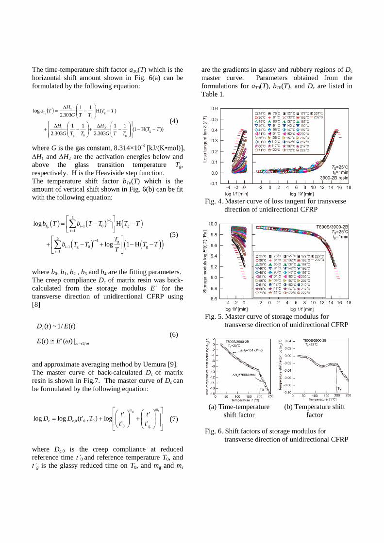
The time-temperature shift factor aT0(T) which is the
horizontal shift amount shown in Fig. 6(a) can be
formulated by the following equation:
))(H1(11
303.2
11
303.2
)(H11
3032alog
g
g
2
0g
1
g
0
1
0
TTTTG
H
TTG
H
TTTTG.
HTT
(4)
where G is the gas constant, 8.314×10⁻³
[kJ/(K•mol)],
H1 and H2 are the activation energies below and
above the glass transition temperature Tg,
respectively. H is the Heaviside step function.
The temperature shift factor bTo(T) which is the
amount of vertical shift shown in Fig. 6(b) can be fit
with the following equation:
0
51
1 0
1
51 g
1 g 0 g
1
log H
log 1 H
i
T i g
i
i
i
i
b T b T T T T
Tb T T T T
T
(5)
where b0, b1, b2 , b3 and b4 are the fitting parameters.
The creep compliance Dc of matrix resin was back-
calculated from the storage modulus E’ for the
transverse direction of unidirectional CFRP using
[8]
)(/1~)(c tEtD
tEtE 2|)(')(
(6)
and approximate averaging method by Uemura [9].
The master curve of back-calculated Dc of matrix
resin is shown in Fig.7. The master curve of Dc can
be formulated by the following equation:
rg
g0
00c,0c'
'
'
'log),'(loglog
mm
t
t
t
tTtDD
(7)
where Dc,0 is the creep compliance at reduced
reference time t’0 and reference temperature T0, and
t’g is the glassy reduced time on T0, and mg and mr
are the gradients in glassy and rubbery regions of Dc
master curve. Parameters obtained from the
formulations for aT0(T), bT0(T), and Dc are listed in
Table 1.
Fig. 4. Master curve of loss tangent for transverse
direction of unidirectional CFRP
Fig. 5. Master curve of storage modulus for
transverse direction of unidirectional CFRP
(a) Time-temperature
shift factor
(b) Temperature shift
factor
Fig. 6. Shift factors of storage modulus for
transverse direction of unidirectional CFRP
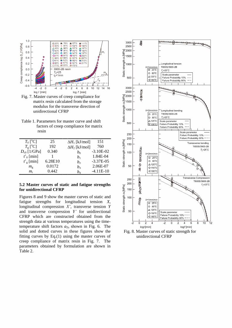
Fig. 7. Master curves of creep compliance for
matrix resin calculated from the storage
modulus for the transverse direction of
unidirectional CFRP
Table 1. Parameters for master curve and shift
factors of creep compliance for matrix
resin
T0 [oC]
Tg [oC]
Dc0 [1/GPa]
t’0 [min]
t’g [min]
mg
mr
25
192
0.340
1
6.28E10
0.0172
0.442
H1 [kJ/mol]
H2 [kJ/mol]
b0
b1
b2
b3
b4
151
760
-3.10E-02
1.84E-04
-3.37E-05
2.06E-07
-4.11E-10
5.2 Master curves of static and fatigue strengths
for unidirectional CFRP
Figures 8 and 9 show the master curves of static and
fatigue strengths for longitudinal tension X,
longitudinal compression X’, transverse tension Y
and transverse compression Y’ for unidirectional
CFRP which are constructed obtained from the
strength data at various temperatures using the time-
temperature shift factors aTo shown in Fig. 6. The
solid and dotted curves in these figures show the
fitting curves by Eq.(1) using the master curves of
creep compliance of matrix resin in Fig. 7. The
parameters obtained by formulation are shown in
Table 2.
Fig. 8. Master curves of static strength for
unidirectional CFRP
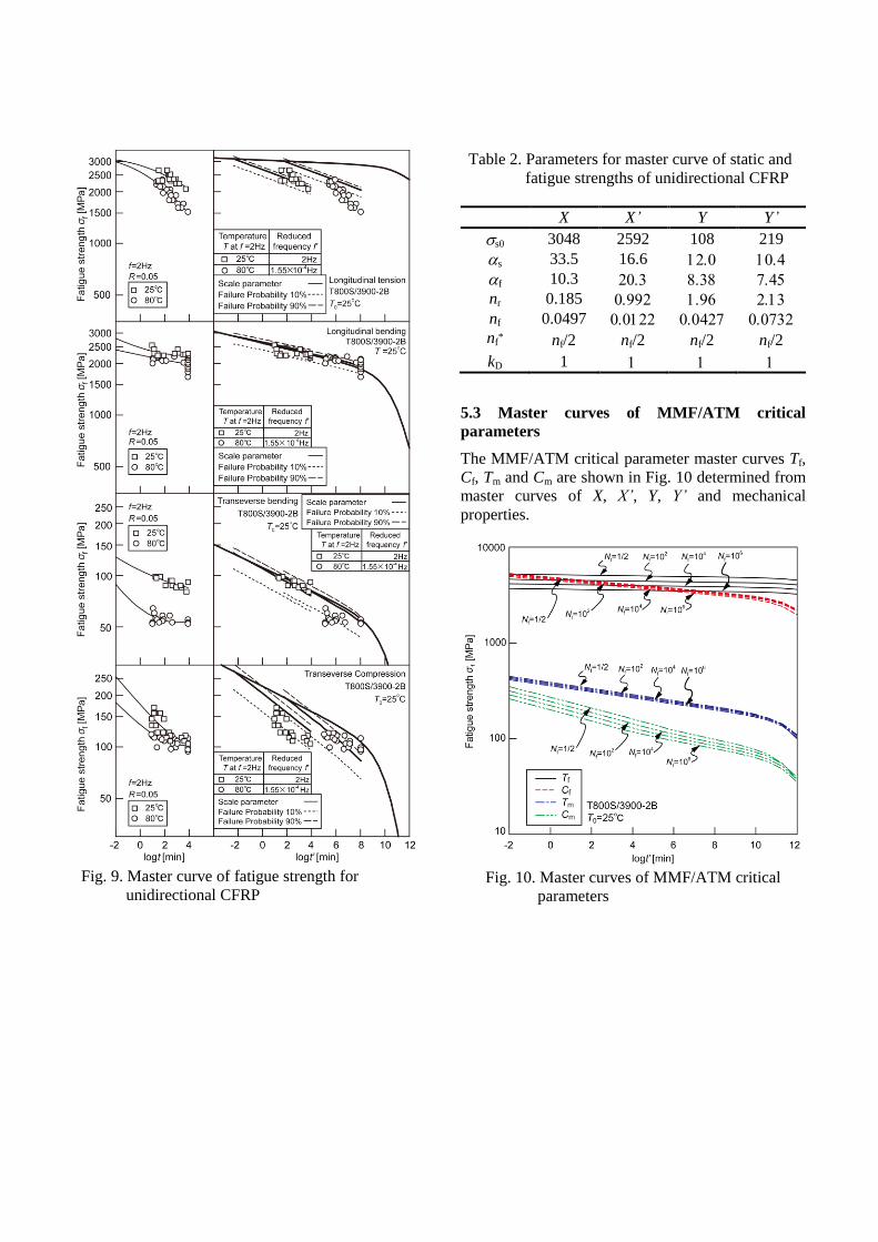
Fig. 9. Master curve of fatigue strength for
unidirectional CFRP
Table 2. Parameters for master curve of static and
fatigue strengths of unidirectional CFRP
X X’ Y Y’
s0 3048 2592 108 219
s 33.5 16.6
f 10.3
nr 0.185
nf 0.0497 nf
* nf/2 nf/2 nf/2 nf/2
kD 1
5.3 Master curves of MMF/ATM critical
parameters
The MMF/ATM critical parameter master curves Tf,
Cf, Tm and Cm are shown in Fig. 10 determined from
master curves of X, X’, Y, Y’ and mechanical
properties.
Fig. 10. Master curves of MMF/ATM critical
parameters

5.4 Prediction of OHC strengths for QIL
As an example of application of MMF/ATM critical
parameters master curves, the long-term OHC
strength for QIL was predicted. Figure 11 shows the
failure index distribution map for static test under
25oC. kTf and kCf are the failure index of fiber under
tension and compression. kTm and kCm are the failure
index of matrix under tension and compression.
Numbers indicate the maximum value of failure
index at the edge of hole in Fig. 11. When one of
these failure indexes reaches to unity, the initial
failure of laminate occurs.
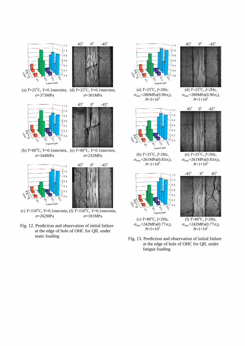
Figures 12(a), (b), and (c) show the failure indexes
of MMF/ATM parameters under static loading. It
can be predicted that the OHC static failure under
T=25oC and 80
oC of QIL was triggered by fiber
compressive failure in 0o layer. The OHC static
failure under T=150oC of QIL was triggered by
matrix compressive failure in ±45o layer. Figures
12(d), (e), and (f) shows the initial failure of OHC
for QIL under static loading observed from the
specimen in which the OHC test was stopped before
final failure under various temperatures. For
T=25oC, and 80
oC, the microbuckling of fiber in 0
o
layer is observed near the edge of hole. For
T=150oC, the transverse crack in 45
o layer is
observed near the edge of hole. These results agree
well with predicted ones.
Figures 13 (a), (b), and (c) show the initial failure
the failure indexes of MMF/ATM parameters under
fatigue loading. It can be predicted that the OHC
fatigue failure of QIL was triggered by matrix
compressive failure in ±45o layer under all
temperature tested. Figures 13(d), (e), and (f) shows
the initial failure of OHC for QIL under fatigue
loading observed from the specimen in which the
OHC test was stopped before final failure. For
fatigue test, the transverse crack in 45o layer is
observed near the edge of hole under all temperature
tested. These results agree well with predicted ones.
Figure 14 shows the predicted master curves of
static and fatigue OHC strengths for QIL with
experimental data. The black and gray solid lines in
the figure are predicted strengths for which the
initial failure is compression of fiber in 0o layer and
compression of matrix in ±45o layer. The predicted
strength for which the initial failure is compression
of fiber in 0o layer agrees well with the experimental
data for all region of time to failure t’.
6 Conclusion
The static and fatigue strengths of quasi-isotropic
CFRP laminates with a central hole under
compression load as an example of CFRP structures
were measured at elevated temperatures, and these
experimental data agreed well with the predicted
results based on MMF/ATM method.
Acknowledgements
The authors thank the Japan Aerospace Exploration
Agency for supporting this work through JAXA
Space Open Laboratory Project.
The authors thank the Office of Naval Research for
supporting this work through an ONR award with Dr.
Yapa Rajapakse as the ONR Program Officer. Our
award is numbered to N62909-12-1-7024 and titled
“Accelerated Testing Methodology for Long-Term
Durability of CFRP Structures for Marine Use”.
The authors thank Professor Richard Christensen at
Stanford University as the consultant of this project.
kTf kCf kTm kCm
45o
layer
0o
layer
-45o
layer
90o
layer
Fig. 11. Failure index distribution map under
static OHC loading for QIL
(T=25oC, V=0.1mm/min, =373MPa)
45o 0
o -45
o
(a) T=25
oC, V=0.1mm/min,
=373MPa
(d) T=25oC, V=0.1mm/min,
=301MPa
45o 0
o -45
o
(b) T=80
oC, V=0.1mm/min,
=344MPa
(e) T=80oC, V=0.1mm/min,
=232MPa
45o 0
o -45
o
(c) T=150
oC, V=0.1mm/min,
=262MPa
(f) T=150oC, V=0.1mm/min,
=181MPa
Fig. 12. Prediction and observation of initial failure
at the edge of hole of OHC for QIL under
static loading
45o 0
o -45
o
(a) T=25
oC, f=2Hz,
max=280MPa(0.90s),
N=3×10³
(d) T=25oC, f=2Hz,
max=280MPa(0.90s),
N=1×10²
45o 0
o -45
o
(b) T=25
oC, f=2Hz,
max=261MPa(0.83s),
N=1×10⁴
(e) T=25oC, f=2Hz,
max=261MPa(0.83s),
N=1×10³
-45o 0
o 45
o
(c) T=80
oC, f=2Hz,
max=242MPa(0.77s),
N=5×10³
(f) T=80oC, f=2Hz,
max=242MPa(0.77s),
N=1×10⁵
Fig. 13. Prediction and observation of initial failure
at the edge of hole of OHC for QIL under
fatigue loading
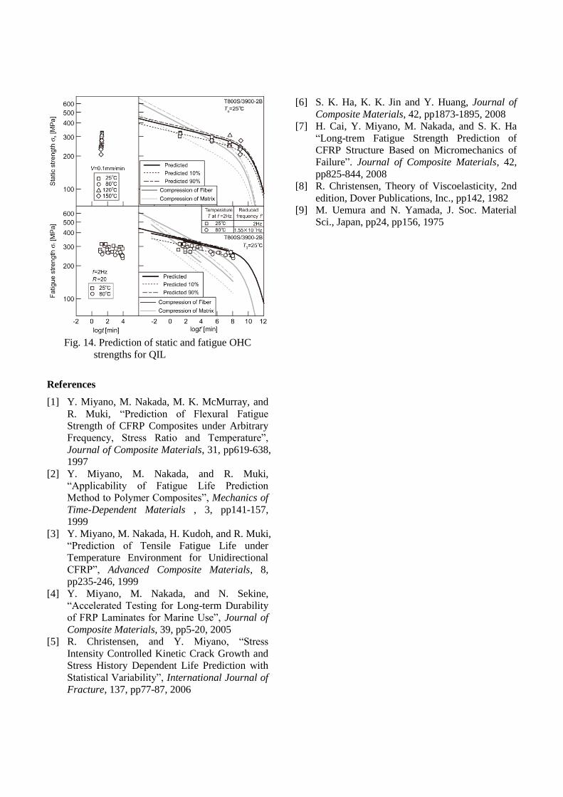
Fig. 14. Prediction of static and fatigue OHC
strengths for QIL
References
[1] Y. Miyano, M. Nakada, M. K. McMurray, and
R. Muki, “Prediction of Flexural Fatigue
Strength of CFRP Composites under Arbitrary
Frequency, Stress Ratio and Temperature”,
Journal of Composite Materials, 31, pp619-638,
1997
[2] Y. Miyano, M. Nakada, and R. Muki, “Applicability of Fatigue Life Prediction
Method to Polymer Composites”, Mechanics of
Time-Dependent Materials , 3, pp141-157,
1999
[3] Y. Miyano, M. Nakada, H. Kudoh, and R. Muki,
“Prediction of Tensile Fatigue Life under
Temperature Environment for Unidirectional
CFRP”, Advanced Composite Materials, 8,
pp235-246, 1999
[4] Y. Miyano, M. Nakada, and N. Sekine,
“Accelerated Testing for Long-term Durability
of FRP Laminates for Marine Use”, Journal of
Composite Materials, 39, pp5-20, 2005
[5] R. Christensen, and Y. Miyano, “Stress
Intensity Controlled Kinetic Crack Growth and
Stress History Dependent Life Prediction with
Statistical Variability”, International Journal of
Fracture, 137, pp77-87, 2006
[6] S. K. Ha, K. K. Jin and Y. Huang, Journal of
Composite Materials, 42, pp1873-1895, 2008
[7] H. Cai, Y. Miyano, M. Nakada, and S. K. Ha
“Long-trem Fatigue Strength Prediction of
CFRP Structure Based on Micromechanics of
Failure”. Journal of Composite Materials, 42,
pp825-844, 2008
[8] R. Christensen, Theory of Viscoelasticity, 2nd
edition, Dover Publications, Inc., pp142, 1982
[9] M. Uemura and N. Yamada, J. Soc. Material
Sci., Japan, pp24, pp156, 1975


![Improvement of Interfacial Shear Strength Using ...confsys.encs.concordia.ca/ICCM19/AllPapers/FinalVersion/RUT80577.pdf · modified by introducing nano, ... the IFSS [15] and, based](https://img.pdfslide.net/doc/110x75/5abd66f07f8b9a8e3f8bba70/improvement-of-interfacial-shear-strength-using-by-introducing-nano-the.jpg)
![MODELING STRUCTURAL BEHAVIOUR OF PVC …confsys.encs.concordia.ca/ICCM19/AllPapers/FinalVersion/...absorption of circular CFRP tubes with diameter/thickness ratio [7] (b) Photograph](https://img.pdfslide.net/doc/110x75/5adb09867f8b9a6d318d8ddd/modeling-structural-behaviour-of-pvc-of-circular-cfrp-tubes-with-diameterthickness.jpg)