Embed Size (px)
Citation preview
Hindawi Publishing CorporationModelling and Simulation in EngineeringVolume 2012, Article ID 468029, 11 pagesdoi:10.1155/2012/468029
Research Article
Prediction of Ship Unsteady Maneuvering in Calm Water bya Fully Nonlinear Ship Motion Model
Ray-Qing Lin, Tim Smith, and Michael Hughes
Hydromechanics Department, David Taylor Model Basin, NSWCCD, 9500 MacArthur Boulevard, West Bethesda,MD 20817-5700, USA
Correspondence should be addressed to Ray-Qing Lin, [email protected]
Received 25 August 2011; Accepted 5 December 2011
Academic Editor: Ahmed Rachid
Copyright © 2012 Ray-Qing Lin et al. This is an open access article distributed under the Creative Commons Attribution License,which permits unrestricted use, distribution, and reproduction in any medium, provided the original work is properly cited.
This is the continuation of our research on development of a fully nonlinear, dynamically consistent, numerical ship motionmodel (DiSSEL). In this study we will report our results in predicting ship motions in unsteady maneuvering in calm water.During the unsteady maneuvering, both the rudder angle, and ship forward speed vary with time. Therefore, not only surge,sway, and yaw motions occur, but roll, pitch and heave motions will also occur even in calm water as heel, trim, and sinkage,respectively. When the rudder angles and ship forward speed vary rapidly with time, the six degrees-of-freedom ship motionsand their interactions become strong. To accurately predict the six degrees-of-freedom ship motions in unsteady maneuvering,a universal method for arbitrary ship hull requires physics-based fully-nonlinear models for ship motion and for rudder forcesand moments. The numerical simulations will be benchmarked by experimental data of the Pre-Contract DDG51 design and anExperimental Hull Form. The benchmarking shows a good agreement between numerical simulations by the enhancement DiSSELand experimental data. No empirical parameterization is used, except for the influence of the propeller slipstream on the rudder,which is included using a flow acceleration factor.
1. Introduction
To predict ship motions in unsteady state maneuvering incalm water, due to both the time-varying angle and shipforward speed, all six degrees-of- freedom ship motions mustbe considered. Particulary, when the rudder angles and shipforward speed vary rapidly with time, the six degrees-of-freedom of ship motions and interactions between differentmodes of motion, as well as between rudder and ship body,become strong. A fully nonlinear method to predict the six-degree freedom of ship motions is need.
With the increase in computer capabilities and the devel-opment of advanced computation flow prediction methods,the use of numerical methods to predict the steeringcapabilities of ships has become possible. For example, Linet al. [1] and Lin and Kuang [2] predicted ship motions insteady turning circles in calm water and seawater by a fullynonlinear hybrid flow ship motion model. Chau [3] and ElMoctar [4] used viscous flow methods to predict the rudderflow and Lee [5], Tamashima et al. [6], Han et al. [7], Kinnas
et al. [8], and Hacket et al. [9] used potential flow panelmethods to compute the rudder force and moment. Notably,Kinnas et al. [8] used a finite element boundary conditionto improve the panel method. Recently, Hochbaum et al.summarized the researches on predicting ship motionswhen ship maneuvering in 25th ITTC conference [10].Many of them are focused on maneuvering in calm water,especially those unsteady maneuvering. These works havesignificantly improved the physical understanding of rudderforces and moments. However, as Soding [11] pointed out,those potential flow methods did not take into accountviscosity, turbulence, and flow separation. Viscous flowmethods for prediction of a ship’s steering capabilities stillremain technically difficult and computationally expensive.Therefore, in spite of the limitations of potential flow, mostpractical flow problems are still solved either by experimentaldata or by potential flow calculations [11].
The current numerical prediction ability cannot satisfythe ship industry’s development needs. Most predictionmethods are still focused on using observed or empirical
2 Modelling and Simulation in Engineering
Rudder angle (DDG51, test 163)
0
5
10
15
0 50 100 150 200 250
Time (s)
Ru
dder
an
gle
(deg
)
−5
−10
−15
(a)
Ship speed (DDG51, test 163)
0
2
4
6
8
10
12
14
0 50 100 150 200
Time (s)
Ship
sp
eed
(m/s
)
(b)
Ship track in calm water (DDG51)
DiSSELData
−300 −200 −100 00
−200
−400
−600
−800
−1000
−1200x (m)
y(m
)
(c)
−8
−6
−4
−2
0
2
4
Ship
mot
ion
(de
g)
Ship motion in calm water (DDG51)
0 50 100 150 200
Time (s)
Roll by DiSSELPitch by DiSSEL
Roll from dataPitch from data
(d)
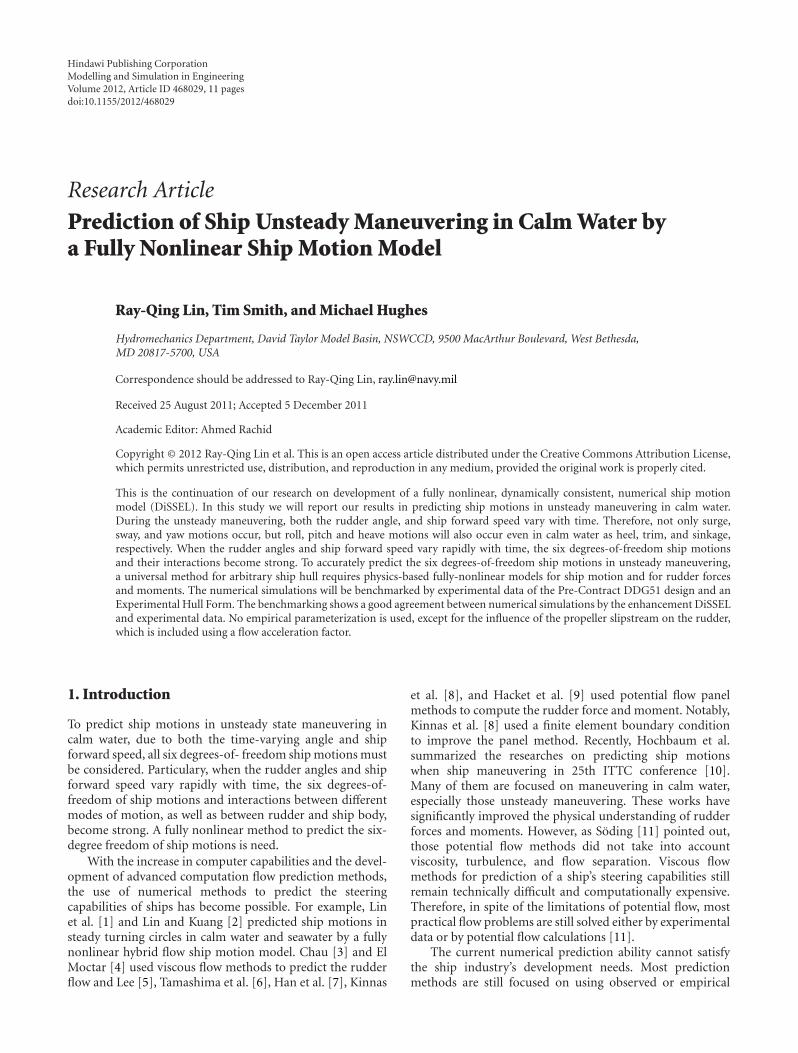
Figure 1: Input data for case 1 are shown in (a) and (b). (a) Rudder angle from data in test 163, (b) ship speed from data in test 163.Benchmark simulations for case 1 are shown in (c) and (d). (c) Comparison of ship tracks between simulation and experimental data in test163, (d) Comparison of roll and pitch motions between simulations and data in test163.
forces and moments on the rudder for steady or unsteadyturning circles. The ship motions often focus on surge,sway, and yaw motions which are calculated by empiricalformulations. For example, Altosloe et al. [12], Kimoto et al.[13], and Katayama et al. [14, 15] are popular in shipindustry because these methods are accurate even for aplaning craft in calm water.
Even though these methods are accurate, they are notappropriate for new and unconventional ships, for whichempirical data are not available. Therefore, in [1, 2], aphysics-based method was described for the prediction offorces and moments on the rudder for steady turningin calm water and in seaway. When this new methodis coupled with a nonlinear six degrees-of-freedom shipmotion model (Digital, Self-consistent Ship ExperimentalLaboratory, we may simply call DiSSEL), the associatedsurge, sway, and yaw can be accurately predicted. The goal inthis study is continue developing a fully nonlinear coupledcomputational system to accurately predict the ship motionfor an unsteady maneuvering ship. Even in calm water, dueto the time-varying ship forward speed and rudder angle,the six degrees-of-freedom ship motions as well as their
interactions (between different modes of ship motion as wellas between the rudder and ship body) all become significant.Therefore, such simulations require a physics-based, fullynonlinear method.
As an example of a fully nonlinear method, the waterlineshould be defined by local free surface elevation (ship wavesand their interactions); the ship position is determined bythe six degrees-of-freedom ship motion; the ship motionsare determined by the force and moment on the wettedsurfaces of the ship hull and of the rudders, and the forceand moment are determined by ship and rudder positions,and so forth. Unfortunately, as a propeller model has notyet been implemented in DiSSEL, the influence of thepropeller slipstream on the rudder is included empiricallyby modifying the effective inflow velocity into the rudder toaccount for the acceleration of the flow by the propeller.
In the following section, a coupled, fully nonlinearrudder force with fully nonlinear ship motion model is pre-sented. Section 3 benchmarks the numerical simulation withexperimental data for two ship hulls: Pre-Contract DDG-51(Model 5514) and Experimental Hull Form. Conclusions areprovided in Section 4.
Modelling and Simulation in Engineering 3
Rudder angle (DDG51, test 166)
0
20
40
0 50 100 150 200 250
Time (s)
Ru
dder
an
gle
(deg
)
−20
(a)
Ship speed (DDG51, test 166)
0123456789
0 50 100 150 200 250 300
Time (s)
Ship
sp
eed
(m/s
)
(b)
Ship track in calm water (DDG51)
0
200
400
600
800
0 500 1000 1500
DiSSELData
x (m)
y(m
)
−500−400
−200
(c)
Ship motion in calm water (DDG51)
0
2
4
6
8
0 50 100 150 200 250
Time (s)
Ship
mot
ion
(de
g)
Roll by DiSSELPitch by DiSSEL
Roll from dataPitch from data
−2
−4
−6
−8
(d)
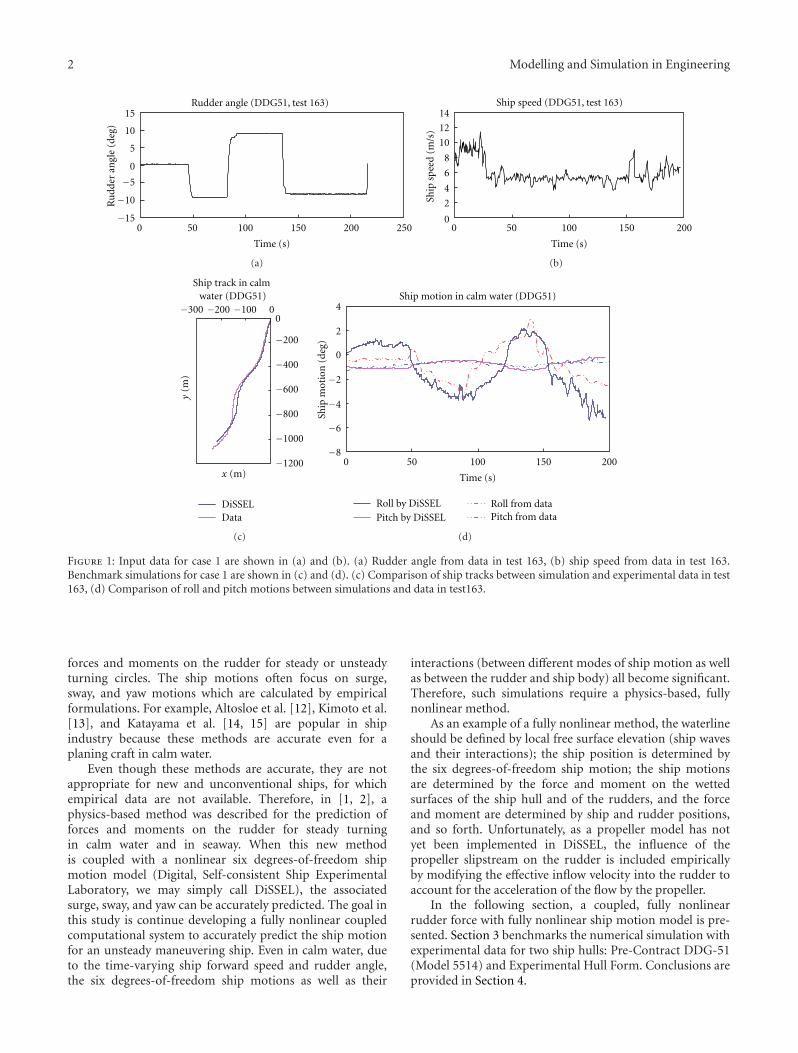
Figure 2: Data input for case 2 are shown in (a) and (b). (a) Rudder angle from data in test 166, (b) ship speed from data in test 166.Benchmark simulations for case 2 are shown in (c) and (d). (c) Comparison of ship track between simulation and experimental data in test166. (d) Comparison of roll and pitch motions between simulations and data in test 166.
2. A Fully Nonlinear PredictionSystem of Steering Capabilitiesand Ship Motion Model
DiSSEL is a hybrid-flow ship motion model in time domain:the surface waves are described by velocity potential, but thefluid viscous effect is included in the form of wave breakingand separation effects (Lin et al. [1], and Lin and Kuang[2, 16]). Inclusion of the viscous, separation effect makesDiSSEL satisfying the Kutta condition at a trailing edge, andvelocity stagnation points (V = 0), thus allowing accurateevaluation of the lift force (Lin et al. [1]; Lin and Kuang [2]).This hybrid-flow approach builds a solid foundation of oureffort to expand the model for ship maneuvering in a seaway.
The fully nonlinear prediction system includes twocomponents. The first component is prediction of rudderforces and moments and the second component is theDiSSEL ship motion model. Before describing the twocomponents, we will overview the method to accuratelypredict flow separation affect in potential flow theory whichwas proposed by Lin and Kuang [16].
2.1. “Blocking Theory” in Potential Flow. Landau and Lifshitz[17] pointed out that flow passing an object causes its
total pressure to change. However, according to potentialflow theory, its total pressure does not change. To correctlycalculate the net pressure on the rudder is the key issue foraccurately predicting the steering capability. Lin and Kuang[16] proposed a “blocking theory” and suggested total lostpressure due to the separation on the object can be obtainedby integrating the pressure over “the affect area” in potentialflow. The “affect area” may be referred to as blocking area orseparated area. When flow passes an object, without viscosityand turbulence, the pressure is P(s). When viscosity andturbulence are present, the pressure P(s) will change to P′(s)on the object surface, and P′(s) < P(s). This is the separationeffect. If Ar is the surface area of the object, then the totalhydrodynamic force on the object is
∫Ar
nP′(s)ds, (1)
where n is normal vector of the object. For a potential flow,P(s) is calculated instead of P′(s). In order to obtain the totalpressure accurately, one can reduce the object surface areafrom Ar to Ar−Ae. Then the total hydrodynamic force onthe object will be:
∫Ar−Ae
nP(s)ds ≈∫
ArnP′(s)ds; (2)
4 Modelling and Simulation in Engineering
Rudder angle (DDG51 test 172b)
0
10
20
30
0 50 100 150 200 250 300 350 400 450
Time (s)
Ru
dder
an
gle
(deg
)
−30
−20
−10
(a)
Ship speed (DDG51 test 172b)
0
2
4
6
8
10
12
14
0 50 100 150 200 250 300 350 400 450
Time (s)
Ship
sp
eed
(m/s
)
(b)
Ship track in calm water (DDG51)
0
500
1000
1500
2000
0 500 1000 1500
DiSSEL
Data
x (m)
y(m
)
(c)
0
5
10
0 50 100 150 200 250 300 350 400
Time (s)
Ship
mot
ion
(de
g)
Roll by DiSSELPitch by DiSSEL
Roll from dataPitch from data
−5
−10
−15
Ship motion in calm water (DDG51)
(d)
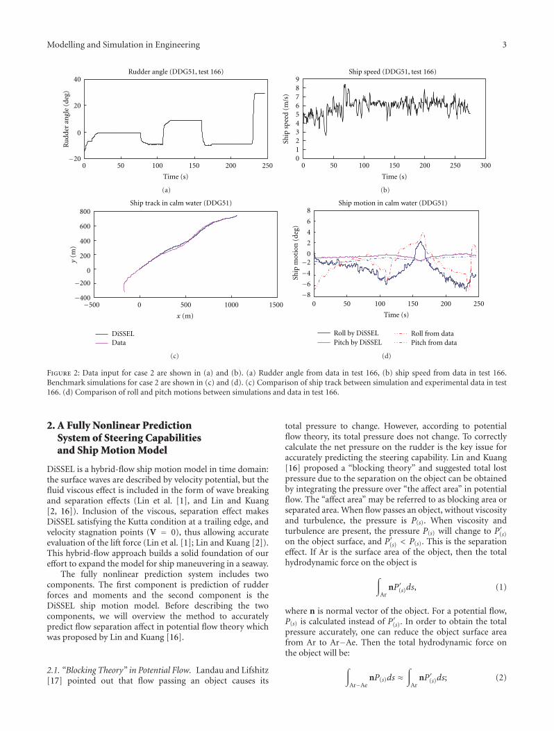
Figure 3: Data input for case 3 are shown in (a) and (b). (a) Rudder angle from data in test 172b, (b) ship speed from data in test 172b.Benchmark simulations for case 3 are shown in (c) and (d). (c) Comparison of ship track between simulation and experimental data in test172b. (d) Comparison of roll and pitch motions between simulations and data in test 172b.
Ae is affected area, and it is a function of object rotationalmotion angles, wave frequency, nature frequency, and wait-ing function of wave amplitudes. In the calm water, Ae isonly a function of object rotational motion angles and naturefrequency.
The separation effect that causes the total hydrodynamicforce reduction in the object can be obtained in potentialflow:
Fseparation-effect = −∫∫
AenP(s)ds. (3)
The separation effect on the moment in the object is
Γseparation-effect = −∫∫
Aer× nP(s)ds, (4)
where r is rotating arm vector of the object. The “blockingtheory” has been well tested with experimental data [16];it can accurately estimate the bilge keels roll damping, T-foil pitch and roll damping, and lift force for steady turningcircles. More details in Lin and Kuang [16].
2.2. Prediction Forces and Moment on Rudder. The effectiveforce and moment on the rudders in the ship coordinatesystem can be expressed as
Frudder =∫∫
A0−A0e
nrPrudder(s)ds
= Fxxs + Fyys + Fzzs + Fcoriolis,
Γrudder =∫∫
A0−A0e
r× nrPrudder(s)ds + (x − xC)× Fcoriolis
= Γrxxs + Γrxys + Γrzzs + (x − xC)× Fcoriolis,(5)
where A0 is total surface area of rudder and A0e is the “affectarea” of rudder. The rudder angle, δ, varies with time asspecified by the input data, and Ωδ is the angular velocityof rudder in ship coordinate. Fzzs is vertical lift forces on therudders and r is rotating arm vector, xs, ys, zs are the threecomponents of unit vectors in the ship-fixed coordinate, xC
is the position vector of the center of the circle tangent tothe point x on the ship trajectory, and nr is rudder surfacenormal vector. Prudder(s) is a pressure on the wetted surfacesof the rudder; Frudder is force on the rudder, and Fcoriolis is
Modelling and Simulation in Engineering 5
Rudder angle (DDG51 test 173)
0
10
20
30
0 50 100 150 200 250 300 350
Time (s)
Ru
dder
an
gle
(deg
)
−10
−20
−30
(a)
Ship speed (DDG51 test 173)
0
2
4
6
8
10
12
0 50 100 150 200 250 300 350
Time (s)
Ship
sp
eed
(m/s
)
(b)
Ship track in calm water (DDG51)
0
400
800
1200
1600
0 500 1000 1500
DiSSELData
−400−500
y(m
)
x (m)
(c)
Ship motion in calm water (DDG51)
0
5
10
15
0 50 100 150 200 250 300 350
Time (s)
Ship
mot
ion
(de
g)
Roll by DiSSELPitch by DiSSEL
Roll from dataPitch from data
−5
−10
(d)
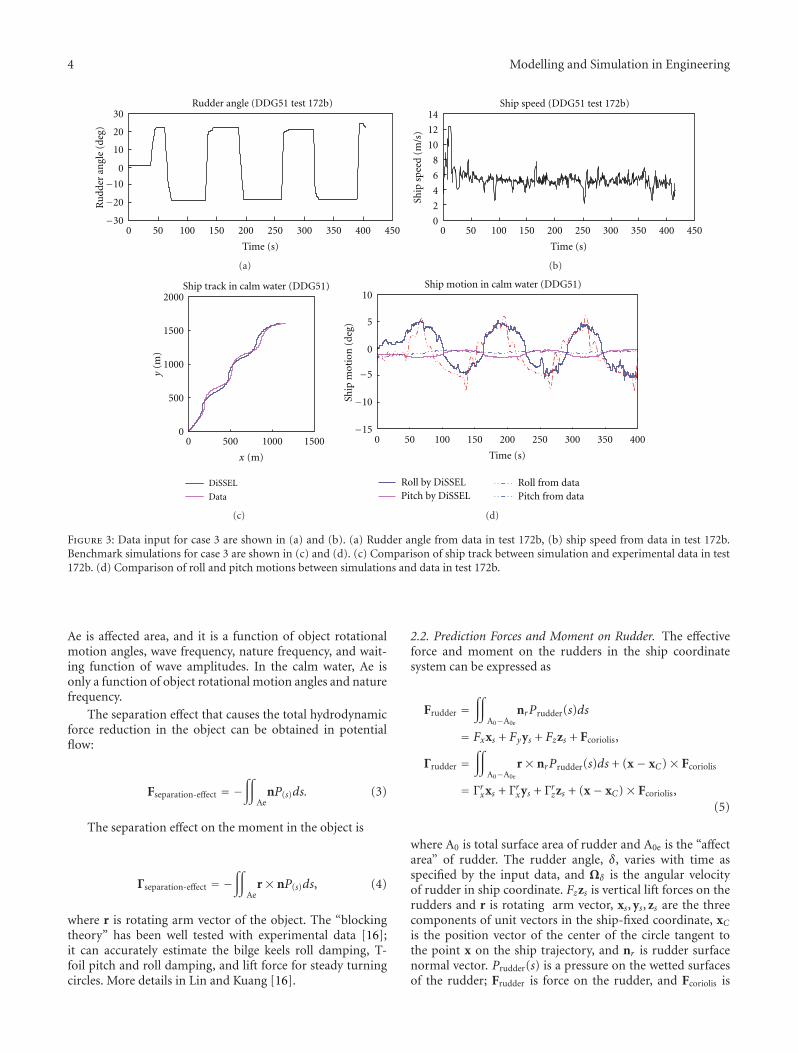
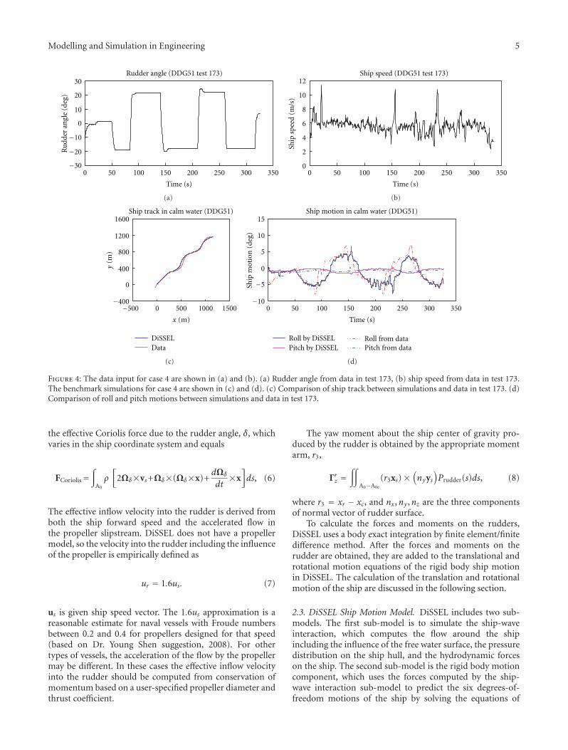
Figure 4: The data input for case 4 are shown in (a) and (b). (a) Rudder angle from data in test 173, (b) ship speed from data in test 173.The benchmark simulations for case 4 are shown in (c) and (d). (c) Comparison of ship track between simulations and data in test 173. (d)Comparison of roll and pitch motions between simulations and data in test 173.
the effective Coriolis force due to the rudder angle, δ, whichvaries in the ship coordinate system and equals
FCoriolis=∫
A0
ρ[
2Ωδ×vs+Ωδ×(Ωδ×x)+dΩδ
dt×x]ds, (6)
The effective inflow velocity into the rudder is derived fromboth the ship forward speed and the accelerated flow inthe propeller slipstream. DiSSEL does not have a propellermodel, so the velocity into the rudder including the influenceof the propeller is empirically defined as
ur = 1.6us. (7)
us is given ship speed vector. The 1.6us approximation is areasonable estimate for naval vessels with Froude numbersbetween 0.2 and 0.4 for propellers designed for that speed(based on Dr. Young Shen suggestion, 2008). For othertypes of vessels, the acceleration of the flow by the propellermay be different. In these cases the effective inflow velocityinto the rudder should be computed from conservation ofmomentum based on a user-specified propeller diameter andthrust coefficient.
The yaw moment about the ship center of gravity pro-duced by the rudder is obtained by the appropriate momentarm, r3,
Γrz =∫∫
A0−A0e
(r3xs)×(nyys
)Prudder(s)ds, (8)
where r3 = xr − xc, and nx,ny ,nz are the three componentsof normal vector of rudder surface.
To calculate the forces and moments on the rudders,DiSSEL uses a body exact integration by finite element/finitedifference method. After the forces and moments on therudder are obtained, they are added to the translational androtational motion equations of the rigid body ship motionin DiSSEL. The calculation of the translation and rotationalmotion of the ship are discussed in the following section.
2.3. DiSSEL Ship Motion Model. DiSSEL includes two sub-models. The first sub-model is to simulate the ship-waveinteraction, which computes the flow around the shipincluding the influence of the free water surface, the pressuredistribution on the ship hull, and the hydrodynamic forceson the ship. The second sub-model is the rigid body motioncomponent, which uses the forces computed by the ship-wave interaction sub-model to predict the six degrees-of-freedom motions of the ship by solving the equations of
6 Modelling and Simulation in Engineering
Rudder angle (experimental hull form, test 429)
0
5
10
15
0 200 400 600 800 1000
Time (s)
Ru
dder
an
gle
(deg
)
−5
−10
−15
(a)
Ship speed (experimental hull form, test 429)
0
2
4
6
8
0 200 400 600 800 1000
Time (s)
Ship
sp
eed
(m/s
)
(b)
Ship track in calm water (experimental hull form)
0
1000
0 500 1000 1500
DiSSELData
−3000
−2000
−1000
y(m
)
x (m)
(c)
Ship motion in calm water(experimental hull form)
0
1
2
3
0 200 400 600 800 1000
Time (s)
Ship
mot
ion
(de
g)
Roll by DiSSELPitch by DiSSEL
Roll from dataPitch from data
−1
(d)
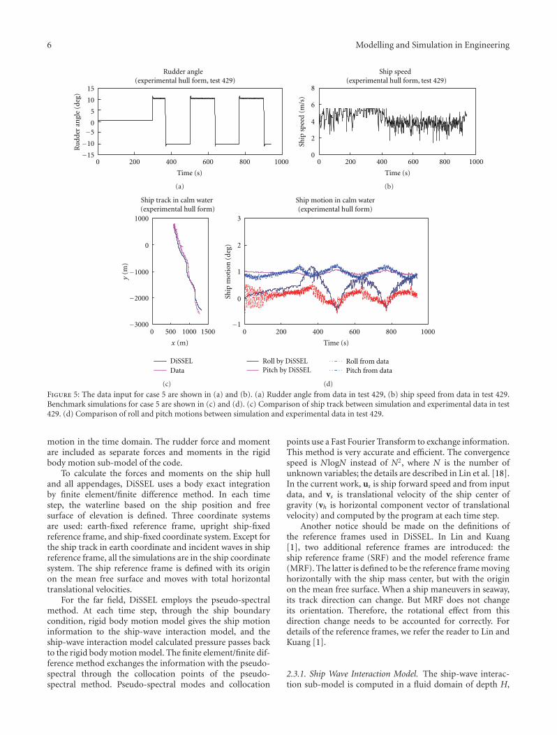
Figure 5: The data input for case 5 are shown in (a) and (b). (a) Rudder angle from data in test 429, (b) ship speed from data in test 429.Benchmark simulations for case 5 are shown in (c) and (d). (c) Comparison of ship track between simulation and experimental data in test429. (d) Comparison of roll and pitch motions between simulation and experimental data in test 429.
motion in the time domain. The rudder force and momentare included as separate forces and moments in the rigidbody motion sub-model of the code.
To calculate the forces and moments on the ship hulland all appendages, DiSSEL uses a body exact integrationby finite element/finite difference method. In each timestep, the waterline based on the ship position and freesurface of elevation is defined. Three coordinate systemsare used: earth-fixed reference frame, upright ship-fixedreference frame, and ship-fixed coordinate system. Except forthe ship track in earth coordinate and incident waves in shipreference frame, all the simulations are in the ship coordinatesystem. The ship reference frame is defined with its originon the mean free surface and moves with total horizontaltranslational velocities.
For the far field, DiSSEL employs the pseudo-spectralmethod. At each time step, through the ship boundarycondition, rigid body motion model gives the ship motioninformation to the ship-wave interaction model, and theship-wave interaction model calculated pressure passes backto the rigid body motion model. The finite element/finite dif-ference method exchanges the information with the pseudo-spectral through the collocation points of the pseudo-spectral method. Pseudo-spectral modes and collocation
points use a Fast Fourier Transform to exchange information.This method is very accurate and efficient. The convergencespeed is NlogN instead of N2, where N is the number ofunknown variables; the details are described in Lin et al. [18].In the current work, us is ship forward speed and from inputdata, and vs is translational velocity of the ship center ofgravity (vh is horizontal component vector of translationalvelocity) and computed by the program at each time step.
Another notice should be made on the definitions ofthe reference frames used in DiSSEL. In Lin and Kuang[1], two additional reference frames are introduced: theship reference frame (SRF) and the model reference frame(MRF). The latter is defined to be the reference frame movinghorizontally with the ship mass center, but with the originon the mean free surface. When a ship maneuvers in seaway,its track direction can change. But MRF does not changeits orientation. Therefore, the rotational effect from thisdirection change needs to be accounted for correctly. Fordetails of the reference frames, we refer the reader to Lin andKuang [1].
2.3.1. Ship Wave Interaction Model. The ship-wave interac-tion sub-model is computed in a fluid domain of depth H,
Modelling and Simulation in Engineering 7
Rudder angle(experimental hull form, test 440)
0
5
10
15
0 200 400 600 800 1000 1200
Time (s)
Ru
dder
an
gle
(deg
)
−5
−10
−15
(a)
Ship speed (experimental hull form, test 440)
0
1
2
3
4
5
0 200 400 600 800 1000 1200
Time (s)
Ship
sp
eed
(m/s
)
(b)
Ship track in calm water (experimental hull form)
0
500
1000
1500
0 500 1000 1500
DiSSELData
−3000
−2500
−2000
−1500
−1000
−500
y(m
)
x (m)
(c)
Ship motion in calm water(experimental hull test 440)
0
0.5
1
1.5
2
2.5
3
0 200 400 600 800 1000 1200
Time (s)
Ship
mot
ion
(de
g)
Roll by DiSSELPitch by DiSSEL
Roll from dataPitch from data
−0.5
−1
−1.5
(d)
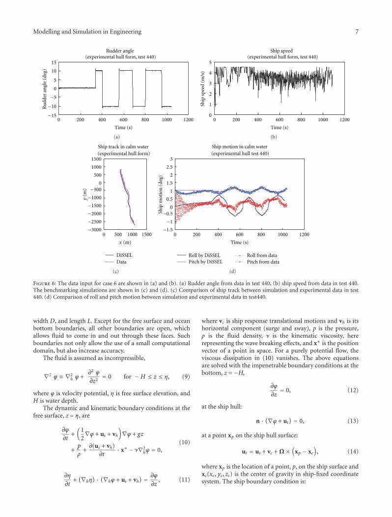
Figure 6: The data input for case 6 are shown in (a) and (b). (a) Rudder angle from data in test 440, (b) ship speed from data in test 440.The benchmarking simulations are shown in (c) and (d). (c) Comparison of ship track between simulation and experimental data in test440. (d) Comparison of roll and pitch motion between simulation and experimental data in test440.
width D, and length L. Except for the free surface and oceanbottom boundaries, all other boundaries are open, whichallows fluid to come in and out through these faces. Suchboundaries not only allow the use of a small computationaldomain, but also increase accuracy.
The fluid is assumed as incompressible,
∇2 ϕ ≡ ∇2h ϕ +
∂2 ϕ
∂z2= 0 for −H ≤ z ≤ η, (9)
where ϕ is velocity potential, η is free surface elevation, andH is water depth.
The dynamic and kinematic boundary conditions at thefree surface, z = η, are
∂ϕ
∂t+(
12∇ϕ + us + vh
)∇ϕ + gz
+p
ρ+∂(us + vh)
∂t· x∗ − ν∇2
hϕ = 0,(10)
∂η
∂t+(∇hη
) · (∇hϕ + us + vh) = ∂ϕ
∂z, (11)
where vc is ship response translational motions and vh is itshorizontal component (surge and sway), p is the pressure,ρ is the fluid density, ν is the kinematic viscosity, hererepresenting the wave breaking effects, and x∗ is the positionvector of a point in space. For a purely potential flow, theviscous dissipation in (10) vanishes. The above equationsare solved with the impenetrable boundary conditions at thebottom, z = −H,
∂ϕ
∂z= 0, (12)
at the ship hull:
n · (∇ϕ + ut) = 0, (13)
at a point xp on the ship hull surface:
ut = us + vc + Ω×(
xp − xc
), (14)
where xp is the location of a point, p, on the ship surface andxc(xc, yc, zc) is the center of gravity in ship-fixed coordinatesystem. The ship boundary condition is:
8 Modelling and Simulation in Engineering
Rudder angle (experimental hull form, test 437)
0
5
10
15
0 100 200 300 400 500
Time (s)
Ru
dder
an
gle
(deg
)
−5
−10
−15
(a)
Ship speed (experimental hull form, test 437)
0
2
4
6
8
10
12
0 100 200 300 400 500
Time (s)
Ship
sp
eed
(m/s
)
(b)
Ship track in calm water (experimental hull form)
0
500
1000
0 500 1000 1500
DiSSELData
−3000
−2500
−2000
−1500
−1000
−500
y(m
)
x (m)
(c)
Ship motion in calm water(experimental hull form)
0
1
2
3
4
0 100 200 300 400 500
Time (s)
Ship
mot
ion
(de
g)
Roll by DiSSELPitch by DiSSEL
Roll from dataPitch from data
−1
−2
(d)
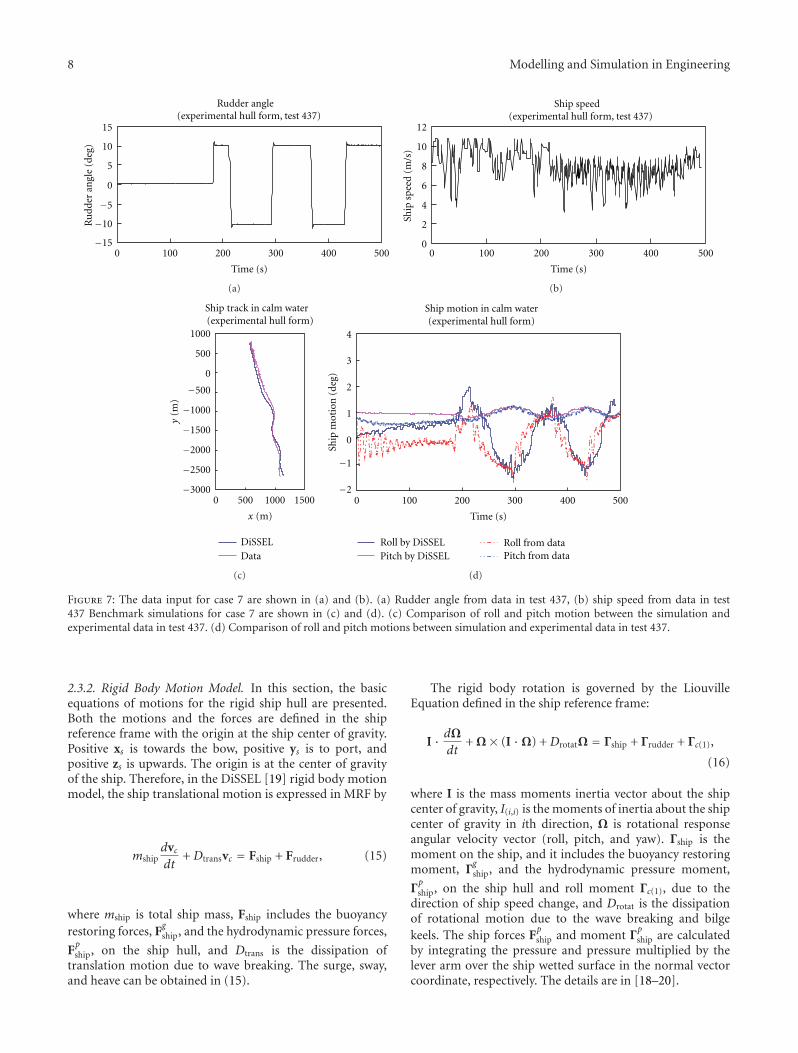
Figure 7: The data input for case 7 are shown in (a) and (b). (a) Rudder angle from data in test 437, (b) ship speed from data in test437 Benchmark simulations for case 7 are shown in (c) and (d). (c) Comparison of roll and pitch motion between the simulation andexperimental data in test 437. (d) Comparison of roll and pitch motions between simulation and experimental data in test 437.
2.3.2. Rigid Body Motion Model. In this section, the basicequations of motions for the rigid ship hull are presented.Both the motions and the forces are defined in the shipreference frame with the origin at the ship center of gravity.Positive xs is towards the bow, positive ys is to port, andpositive zs is upwards. The origin is at the center of gravityof the ship. Therefore, in the DiSSEL [19] rigid body motionmodel, the ship translational motion is expressed in MRF by
mshipdvcdt
+ Dtransvc = Fship + Frudder, (15)
where mship is total ship mass, Fship includes the buoyancyrestoring forces, F
gship, and the hydrodynamic pressure forces,
Fpship, on the ship hull, and Dtrans is the dissipation of
translation motion due to wave breaking. The surge, sway,and heave can be obtained in (15).
The rigid body rotation is governed by the LiouvilleEquation defined in the ship reference frame:
I · dΩdt
+ Ω× (I ·Ω) + DrotatΩ = Γship + Γrudder + Γc(1),
(16)
where I is the mass moments inertia vector about the shipcenter of gravity, I(i,i) is the moments of inertia about the shipcenter of gravity in ith direction, Ω is rotational responseangular velocity vector (roll, pitch, and yaw). Γship is themoment on the ship, and it includes the buoyancy restoringmoment, Γ
gship, and the hydrodynamic pressure moment,
Γpship, on the ship hull and roll moment Γc(1), due to the
direction of ship speed change, and Drotat is the dissipationof rotational motion due to the wave breaking and bilgekeels. The ship forces F
pship and moment Γ
pship are calculated
by integrating the pressure and pressure multiplied by thelever arm over the ship wetted surface in the normal vectorcoordinate, respectively. The details are in [18–20].
Modelling and Simulation in Engineering 9
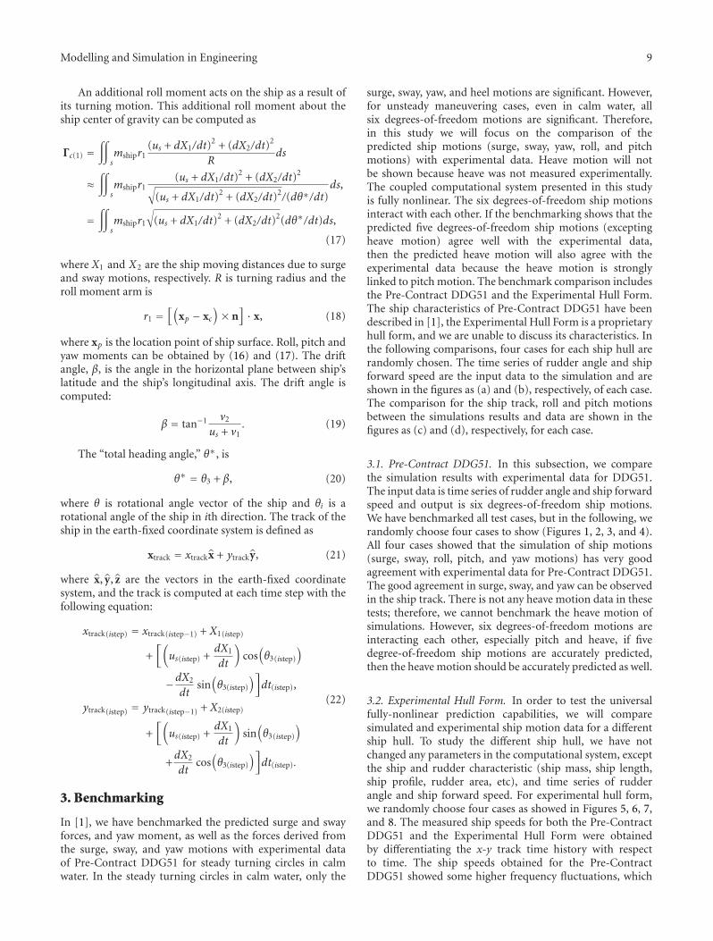
An additional roll moment acts on the ship as a result ofits turning motion. This additional roll moment about theship center of gravity can be computed as
Γc(1) =∫∫
smshipr1
(us + dX1/dt)2 + (dX2/dt)
2
Rds
≈∫∫
smshipr1
(us + dX1/dt)2 + (dX2/dt)
2
√(us + dX1/dt)
2 + (dX2/dt)2/(dθ∗/dt)
ds,
=∫∫
smshipr1
√(us + dX1/dt)
2 + (dX2/dt)2(dθ∗/dt)ds,
(17)
where X1 and X2 are the ship moving distances due to surgeand sway motions, respectively. R is turning radius and theroll moment arm is
r1 =[(
xp − xc
)× n
]· x, (18)
where xp is the location point of ship surface. Roll, pitch andyaw moments can be obtained by (16) and (17). The driftangle, β, is the angle in the horizontal plane between ship’slatitude and the ship’s longitudinal axis. The drift angle iscomputed:
β = tan−1 v2
us + v1. (19)
The “total heading angle,” θ∗, is
θ∗ = θ3 + β, (20)
where θ is rotational angle vector of the ship and θi is arotational angle of the ship in ith direction. The track of theship in the earth-fixed coordinate system is defined as
xtrack = xtrackx + ytracky, (21)
where x, y, z are the vectors in the earth-fixed coordinatesystem, and the track is computed at each time step with thefollowing equation:
xtrack(istep) = xtrack(istep−1) + X1(istep)
+[(
us(istep) +dX1
dt
)cos(θ3(istep)
)
−dX2
dtsin(θ3(istep)
)]dt(istep),
ytrack(istep) = ytrack(istep−1) + X2(istep)
+[(
us(istep) +dX1
dt
)sin(θ3(istep)
)
+dX2
dtcos(θ3(istep)
)]dt(istep).
(22)
3. Benchmarking
In [1], we have benchmarked the predicted surge and swayforces, and yaw moment, as well as the forces derived fromthe surge, sway, and yaw motions with experimental dataof Pre-Contract DDG51 for steady turning circles in calmwater. In the steady turning circles in calm water, only the
surge, sway, yaw, and heel motions are significant. However,for unsteady maneuvering cases, even in calm water, allsix degrees-of-freedom motions are significant. Therefore,in this study we will focus on the comparison of thepredicted ship motions (surge, sway, yaw, roll, and pitchmotions) with experimental data. Heave motion will notbe shown because heave was not measured experimentally.The coupled computational system presented in this studyis fully nonlinear. The six degrees-of-freedom ship motionsinteract with each other. If the benchmarking shows that thepredicted five degrees-of-freedom ship motions (exceptingheave motion) agree well with the experimental data,then the predicted heave motion will also agree with theexperimental data because the heave motion is stronglylinked to pitch motion. The benchmark comparison includesthe Pre-Contract DDG51 and the Experimental Hull Form.The ship characteristics of Pre-Contract DDG51 have beendescribed in [1], the Experimental Hull Form is a proprietaryhull form, and we are unable to discuss its characteristics. Inthe following comparisons, four cases for each ship hull arerandomly chosen. The time series of rudder angle and shipforward speed are the input data to the simulation and areshown in the figures as (a) and (b), respectively, of each case.The comparison for the ship track, roll and pitch motionsbetween the simulations results and data are shown in thefigures as (c) and (d), respectively, for each case.
3.1. Pre-Contract DDG51. In this subsection, we comparethe simulation results with experimental data for DDG51.The input data is time series of rudder angle and ship forwardspeed and output is six degrees-of-freedom ship motions.We have benchmarked all test cases, but in the following, werandomly choose four cases to show (Figures 1, 2, 3, and 4).All four cases showed that the simulation of ship motions(surge, sway, roll, pitch, and yaw motions) has very goodagreement with experimental data for Pre-Contract DDG51.The good agreement in surge, sway, and yaw can be observedin the ship track. There is not any heave motion data in thesetests; therefore, we cannot benchmark the heave motion ofsimulations. However, six degrees-of-freedom motions areinteracting each other, especially pitch and heave, if fivedegree-of-freedom ship motions are accurately predicted,then the heave motion should be accurately predicted as well.
3.2. Experimental Hull Form. In order to test the universalfully-nonlinear prediction capabilities, we will comparesimulated and experimental ship motion data for a differentship hull. To study the different ship hull, we have notchanged any parameters in the computational system, exceptthe ship and rudder characteristic (ship mass, ship length,ship profile, rudder area, etc), and time series of rudderangle and ship forward speed. For experimental hull form,we randomly choose four cases as showed in Figures 5, 6, 7,and 8. The measured ship speeds for both the Pre-ContractDDG51 and the Experimental Hull Form were obtainedby differentiating the x-y track time history with respectto time. The ship speeds obtained for the Pre-ContractDDG51 showed some higher frequency fluctuations, which
10 Modelling and Simulation in Engineering
Rudder angle (experimental hull form, test 439)
0
5
10
15
0 100 200 300 400 500
Time (s)
Ru
ll an
gle
(deg
)
−15
−10
−5
(a)
Ship speed (experimental hull form, test 439)
0
2
4
6
8
10
12
0 100 200 300 400 500
Time (s)
Ship
sp
eed
(m/s
)
(b)
Ship track in calm water (experimental hull form)
0
500
1000
1500
0 500 10001500
DiSSELData
−500
−1000
−1500
−2000
−2500
−3000
y(m
)
x (m)
(c)
Ship motion in calm water(experimental hull form)
0
1
2
3
4
0 100 200 300 400 500
Time (s)
Ship
mot
ion
(de
g)
Roll by DiSSELPitch by DiSSEL
Roll from dataPitch from data
−1
−2
(d)
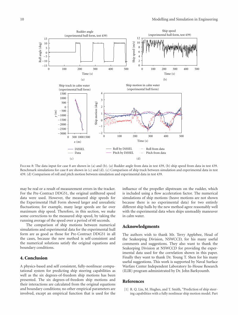
Figure 8: The data input for case 8 are shown in (a) and (b). (a) Rudder angle from data in test 439, (b) ship speed from data in test 439.Benchmark simulations for case 8 are shown in (c) and (d). (c) Comparison of ship track between simulation and experimental data in test439. (d) Comparison of roll and pitch motion between simulation and experimental data in test 439.
may be real or a result of measurement errors in the tracker.For the Pre-Contract DDG51, the original unfiltered speeddata were used. However, the measured ship speeds forthe Experimental Hull Form showed larger and unrealisticfluctuations; for example, many large speeds are far overmaximum ship speed. Therefore, in this section, we makesome corrections to the measured ship speed, by taking therunning average of the speed over a period of 60 seconds.
The comparison of ship motions between numericalsimulations and experimental data for the experimental hullform are as good as those for Pre-Contract DDG51 in allthe cases, because the new method is self-consistent andthe numerical solutions satisfy the original equations andboundary conditions.
4. Conclusion
A physics-based and self consistent, fully-nonlinear compu-tational system for predicting ship steering capabilities aswell as the six degrees-of-freedom ship motions has beenpresented. The six degrees-of-freedom ship motions andtheir interactions are calculated from the original equationsand boundary conditions; no other empirical parameters areinvolved, except an empirical function that is used for the
influence of the propeller slipstream on the rudder, whichis included using a flow acceleration factor. The numericalsimulations of ship motions (heave motions are not shownbecause there is no experimental data) for two entirelydifferent ship hulls by the new method agree reasonably wellwith the experimental data when ships unsteadily maneuverin calm water.
Acknowledgments
The authors wish to thank Mr. Terry Applebee, Head ofthe Seakeeping Division, NSWCCD, for his many usefulcomments and suggestions. They also want to thank theSeakeeping Division at NSWCCD for providing the exper-imental data used for the correlation shown in this paper.Finally they want to thank Dr. Young T. Shen for his manyuseful suggestions. This work is supported by Naval SurfaceWarfare Center Independent Laboratory In-House Research(ILIR) program administrated by Dr. John Barkyoumb.
References
[1] R. Q. Lin, M. Hughes, and T. Smith, “Prediction of ship steer-ing capabilities with a fully nonlinear ship motion model. Part
Modelling and Simulation in Engineering 11
1: maneuvering in calm water,” Journal of Marine Science andTechnology, vol. 15, no. 2, pp. 131–142, 2010.
[2] R.-Q. Lin and W. Kuang, “A fully nonlinear, dynamicallyconsistent numerical model for ship maneuvering in a seaway,”Modeling and Simulation in Engineer, vol. 2011, Article ID356741, 10 pages, 2011.
[3] S. W. Chau, “Computation of rudder force and moment inuniform flow,” Ship Technology Research, vol. 45, no. 1, pp. 3–13, 1998.
[4] O. M. El Moctar, “Numerical determination of rudder forces,”Euromech 374, Poities, 1998.
[5] J.-T. Lee, “A potential based panel method for the analysisof marine propellers in steady flow,” Tech. Rep. 87-13,Department of Ocean Engineering, MIT, 1988.
[6] M. Tamashima, S. Matsui, J. Yang, K. Mori, and R. Yamazaki,“The method for predicting the performance of propeller-rudder system with rudder angles and its application torudder design,” Transaction of the West-Japan Society of NavalArchitects, vol. 86, pp. 53–76, 1993.
[7] J. M. Han, D. S. Kong, I. H. Song, and C. S. Lee, “Analysis ofthe cavitating flow around the horn-type rudder in the race ofpropeller,” in Proceedings of the 4th International Symposiumon Cavitation, pp. 20–23, California Institute of Technology,Pasadena, Calif, USA, June 2001.
[8] S. A. Kinnas, H. Lee, H. Gu, and S. Natarajan, “Prediction ofsheet cavitation on a rudder subject to propeller flow,” Journalof Ship Research, vol. 51, no. 1, pp. 65–75, 2007.
[9] J. P. Hacket, C. O. E. Burgh, and W. H. Brewer, “Man-ufacturing tolerance effects on ship rudder force/cavitationperformance,” in Proceedings of the SNAME Marine TechnologyConference and Expo and Ship Production Symposium, Hous-ton, Tex, USA, October 2005.
[10] A. C. Hochbaum, F. Stern, K. Agdrup et al., “Final Report andRecommendations to 25th ITTC,” in Proceedings of the 25thInternational Towing Tank Conference (ITTC ’08), vol. I, pp.143–208, Fukuoka, Japan, September 2008.
[11] H. Soding, “Limits of potential theory in rudder flow pre-dictions,” in Proceedings of the 22nd Symposium on NavalHydrodynamics, Weinblum Lecture, pp. 622–637, Washington,DC, USA, 1999.
[12] M. Altosloe, M. Figari, and M. Viviani, “6DOF simulationof maneuvering and propulsive performance of waterjetpropelled Mega Yacht,” Fast2009, Athens, Greece, 2009.
[13] R. Kimoto, T. Katayama, and Y. Ikeda, “Effects of runningattitude on hydrodynamic forces for oblique towed planingcraft,” in Proceedings of the 2nd Asia-Pacific Workshop onHydrodynamics (APHydro ’04), pp. 115–122, Busan, Korea,2004.
[14] T. Katayama, R. Kimoto, and Y. Ikeda, “Effects of runningattitudes on maneuvering hydrodynamic forces for planinghull,” in Proceedings of the International Conference on Fast SeaTransportation (FAST ’05), Petersburg, Russia, 2005.
[15] T. Katayama, T. Taniguchi, H. Fujii, and Y. Ikeda, “Devel-opment of maneuvering simulation method for high speedcraft using hydrodynamic forces obtained from model tests,”Fast2009, Athens, Greece, 2009.
[16] R. Q. Lin and W. Kuang, “Modeling nonlinear roll dampingwith a self-consistent, strongly nonlinear ship motion model,”Journal of Marine Science and Technology, vol. 13, no. 2, pp.127–137, 2008.
[17] L. D. Landau and E. M. Lifshitz, Fluid Mechanics, PergamonPress, Oxford, UK, 1987.
[18] R. Q. Lin, W. Kuang, and A. M. Reed, “Numerical modelingof nonlinear interactions between ships and surface gravity
waves, part 1: Ship waves in calm water,” Journal of ShipResearch, vol. 49, no. 1, pp. 1–11, 2005.
[19] R.-Q. Lin and W. Kuang, “A fully nonlinear, dynamicallyconsistent numerical model for solid-body ship motion. I.Ship motion with fixed heading,” Proceeding of Royal SocietyA, vol. 467, no. 2128, pp. 911–927, 2011.
[20] R.-Q. Lin and W. Kuang, “Numerical modeling of nonlinearinteractions between ships and surface gravity waves II: shipboundary condition,” Journal of Ship Research, vol. 50, no. 2,pp. 181–186, 2006.

International Journal of
AerospaceEngineeringHindawi Publishing Corporationhttp://www.hindawi.com Volume 2010
RoboticsJournal of
Hindawi Publishing Corporationhttp://www.hindawi.com Volume 2014
Hindawi Publishing Corporationhttp://www.hindawi.com Volume 2014
Active and Passive Electronic Components
Control Scienceand Engineering
Journal of
Hindawi Publishing Corporationhttp://www.hindawi.com Volume 2014
International Journal of
RotatingMachinery
Hindawi Publishing Corporationhttp://www.hindawi.com Volume 2014
Hindawi Publishing Corporation http://www.hindawi.com
Journal ofEngineeringVolume 2014
Submit your manuscripts athttp://www.hindawi.com
VLSI Design
Hindawi Publishing Corporationhttp://www.hindawi.com Volume 2014
Hindawi Publishing Corporationhttp://www.hindawi.com Volume 2014
Shock and Vibration
Hindawi Publishing Corporationhttp://www.hindawi.com Volume 2014
Civil EngineeringAdvances in
Acoustics and VibrationAdvances in
Hindawi Publishing Corporationhttp://www.hindawi.com Volume 2014
Hindawi Publishing Corporationhttp://www.hindawi.com Volume 2014
Electrical and Computer Engineering
Journal of
Advances inOptoElectronics
Hindawi Publishing Corporation http://www.hindawi.com
Volume 2014
The Scientific World JournalHindawi Publishing Corporation http://www.hindawi.com Volume 2014
SensorsJournal of
Hindawi Publishing Corporationhttp://www.hindawi.com Volume 2014
Modelling & Simulation in EngineeringHindawi Publishing Corporation http://www.hindawi.com Volume 2014
Hindawi Publishing Corporationhttp://www.hindawi.com Volume 2014
Chemical EngineeringInternational Journal of Antennas and
Propagation
International Journal of
Hindawi Publishing Corporationhttp://www.hindawi.com Volume 2014
Hindawi Publishing Corporationhttp://www.hindawi.com Volume 2014
Navigation and Observation
International Journal of
Hindawi Publishing Corporationhttp://www.hindawi.com Volume 2014
DistributedSensor Networks
International Journal of