Embed Size (px)
Citation preview
Brett A. Bednarcyk
Ohio Aerospace Institute, Brook Park,Ohio
Steven M. Arnold
Glenn Research Center, Cleveland, Ohio
Craig S. Collier and Phillip W. Yarrington
Collier Research Corporation, Hampton, Virginia
Preliminary Structural Sizing and Alternative
Material Trade Study of CEV Crew Module
NASA/TM—2007-214947
August 2007
AIAA–2007–2175

NASA STI Program . . . in Profile
Since its founding, NASA has been dedicated to the
advancement of aeronautics and space science. The
NASA Scientific and Technical Information (STI)
program plays a key part in helping NASA maintain
this important role.
The NASA STI Program operates under the auspices
of the Agency Chief Information Officer. It collects,
organizes, provides for archiving, and disseminates
NASA’s STI. The NASA STI program provides access
to the NASA Aeronautics and Space Database and its
public interface, the NASA Technical Reports Server,
thus providing one of the largest collections of
aeronautical and space science STI in the world.
Results are published in both non-NASA channels and
by NASA in the NASA STI Report Series, which
includes the following report types:
• TECHNICAL PUBLICATION. Reports of
completed research or a major significant phase
of research that present the results of NASA
programs and include extensive data or theoretical
analysis. Includes compilations of significant
scientific and technical data and information
deemed to be of continuing reference value.
NASA counterpart of peer-reviewed formal
professional papers but has less stringent
limitations on manuscript length and extent of
graphic presentations.
• TECHNICAL MEMORANDUM. Scientific
and technical findings that are preliminary or
of specialized interest, e.g., quick release
reports, working papers, and bibliographies that
contain minimal annotation. Does not contain
extensive analysis.
• CONTRACTOR REPORT. Scientific and
technical findings by NASA-sponsored
contractors and grantees.
• CONFERENCE PUBLICATION. Collected
papers from scientific and technical
conferences, symposia, seminars, or other
meetings sponsored or cosponsored by NASA.
• SPECIAL PUBLICATION. Scientific,
technical, or historical information from
NASA programs, projects, and missions, often
concerned with subjects having substantial
public interest.
• TECHNICAL TRANSLATION. English-
language translations of foreign scientific and
technical material pertinent to NASA’s mission.
Specialized services also include creating custom
thesauri, building customized databases, organizing
and publishing research results.
For more information about the NASA STI
program, see the following:
• Access the NASA STI program home page at
http://www.sti.nasa.gov
• E-mail your question via the Internet to
• Fax your question to the NASA STI Help Desk
at 301–621–0134
• Telephone the NASA STI Help Desk at
301–621–0390
• Write to:
NASA Center for AeroSpace Information (CASI)
7115 Standard Drive
Hanover, MD 21076–1320
Brett A. Bednarcyk
Ohio Aerospace Institute, Brook Park,Ohio
Steven M. Arnold
Glenn Research Center, Cleveland, Ohio
Craig S. Collier and Phillip W. Yarrington
Collier Research Corporation, Hampton, Virginia
Preliminary Structural Sizing and Alternative
Material Trade Study of CEV Crew Module
NASA/TM—2007-214947
August 2007
National Aeronautics and
Space Administration
Glenn Research Center
Cleveland, Ohio 44135
Prepared for the
48th Structures, Structural Dynamics, and Materials (SDM) Conference
cosponsored by the AIAA, ASME, ASCE, AHS, and ASC
Honolulu, Hawaii, April 23–26, 2007
AIAA–2007–2175
Acknowledgments
The authors acknowledge the financial support of the 2006 NESC composite CM project, led by Michael Kirsch of the NESC
and Thomas Gates of NASA Langley Research Center (LaRC). They also thank Robert Allen of ZIN Technologies for finite
element analysis work on the monocoque CM concept, Ian Fernandez and Hiro Miura of NASA Ames Research Center (ARC)
for providing the finite element model for the geometrically stiffened CM concept, and Winifred Feldhaus and David Sleight
for providing the finite element model for the stiffened sandwich CM concept.
Available from
NASA Center for Aerospace Information
7115 Standard Drive
Hanover, MD 21076–1320
National Technical Information Service
5285 Port Royal Road
Springfield, VA 22161
Available electronically at http://gltrs.grc.nasa.gov
Level of Review: This material has been technically reviewed by technical management.
Trade names and trademarks are used in this report for identification
only. Their usage does not constitute an official endorsement,
either expressed or implied, by the National Aeronautics and
Space Administration.
NASA/TM—2007-214947 1
Preliminary Structural Sizing and Alternative Material Trade Study for CEV Crew Module
Brett A. Bednarcyk
Ohio Aerospace Institute Brook Park, Ohio 44142
Steven M. Arnold
National Aeronautics and Space Administration Glenn Research Center Cleveland, Ohio 44135
Craig S. Collier and Phillip W. Yarrington
Collier Research Corporation Hampton, Virginia 23669
Abstract This paper presents the results of a preliminary structural sizing and alternate material trade study for
NASA’s Crew Exploration Vehicle (CEV) Crew Module (CM). This critical CEV component will house the astronauts during ascent, docking with the International Space Station, reentry, and landing. The alternate material design study considers three materials beyond the standard metallic (aluminum alloy) design that resulted from an earlier NASA Smart Buyer Team analysis. These materials are graphite/epoxy composite laminates, discontinuously reinforced SiC/Al (DRA) composites, and a novel integrated panel material/concept known as WebCore. Using the HyperSizer (Collier Research and Development Corporation) structural sizing software and NASTRAN finite element analysis code, a comparison is made among these materials for the three composite CM concepts considered by the 2006 NASA Engineering and Safety Center Composite Crew Module project.
I. Introduction In an effort to develop a strong in-house understanding of the design drivers for the CEV CM
(see fig. 1), NASA formed a multi-center Smart Buyer Team in January 2006 to perform a preliminary design. This 10 week effort focused on a grid-stiffened aluminum-lithium (Al-Li) design with ring frames and longerons, but also considered composite materials through a simple material substitution. It was determined that composites could potentially deliver a 12 percent mass savings (ref. 1), with even greater mass savings possible through tailoring the overall design to composites. In order to pursue these additional mass savings, the NASA Engineering and Safety Center (NESC) formed a multi-center composite CM team to perform a preliminary design and characterize additional design drivers as they apply to composites, such as manufacturability, crashworthiness, damage tolerance, inspectability, reparability, and the effects of micro-meteoroid orbital debris (MMOD) impacts (ref. 2). This team concluded its work after four months, in September 2006. A second phase of the NESC composite CM project commenced in January 2007, with the goal of completing the design and fabrication of a composite CM in 18 months.
This paper presents the authors’ contributions to the 2006 NESC composite CM project. These contributions primarily involve preliminary design trade studies among materials and panel concepts across the three major CM concepts investigated by the team (see fig. 2). The focus of the present paper is on identifying weight advantages, while other important design issues (manufacturability, inspectability, etc.) are not addressed herein. Trade studies were performed using the HyperSizer structural sizing software (ref. 3), in conjunction with the NASTRAN finite element analysis (FEA) software (ref. 4).
NASA/TM—2007-214947 2
HyperSizer utilizes panel and beam loads from the FEA model to evaluate a wide array of panel and beam concepts and geometries with respect to numerous composite strength and stability failure criteria. Each panel and beam component (which may be composed of several elements) is sized based on its local, statistically processed loads to determine the lightest panel/beam design that produces positive margins for all applicable failure criteria. The optimum designs are chosen from a group of (typically several thousand) candidate designs specified by the user through material/layup choices and geometric variable (e.g., honeycomb core thickness) ranges and permutations. The lightest workable panel and beam concepts as determined by HyperSizer are then automatically included within a new finite element model to be re-evaluated by NASTRAN. New loads are then obtained from the NASTRAN output, enabling updated optimized designs of the panels and beams to be determined by HyperSizer. This process is iterated until convergence of the overall design has been achieved, as indicated by a (nearly) stable weight and design. A new software product, called HyperFEA (ref. 5) now automates this iterative process between the HyperSizer and NASTRAN software packages, streamlining the preliminary design process considerably.
In addition to the IM7/977-2 graphite/epoxy composite (considered to be the baseline composite material for the NESC composite CM project), discontinuously reinforced aluminum (DRA) (ref. 6) and WebCore (refs. 7 and 8) materials were considered. DRA is an aluminum matrix composite with silicon carbide inclusions that can be cast, rolled, or extruded. WebCore is a sandwich panel core material consisting of a fiber reinforced foam, with or without open regions and integral polymer matrix composite
(c) (a) (b)
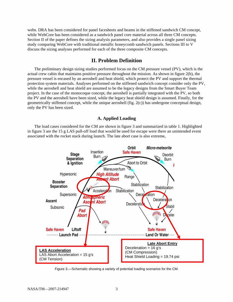
Figure 2.—Design concepts considered for the composite CM: (a) Stiffened sandwich, (b) Monocoque, (c) Geometrically stiffened.
Aeroshell
Heat shield
PV
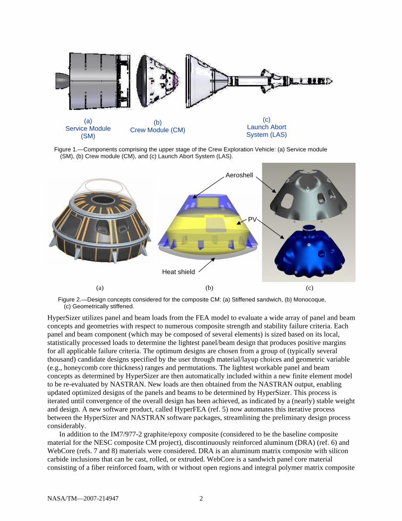
Figure 1.—Components comprising the upper stage of the Crew Exploration Vehicle: (a) Service module (SM), (b) Crew module (CM), and (c) Launch Abort System (LAS).
(a) Service Module
(SM)
(b) Crew Module (CM)
(c) Launch Abort System (LAS)
NASA/TM—2007-214947 3
webs. DRA has been considered for panel facesheets and beams in the stiffened sandwich CM concept, while WebCore has been considered as a sandwich panel core material across all three CM concepts. Section II of the paper defines the sizing analysis parameters, and also provides a single panel sizing study comparing WebCore with traditional metallic honeycomb sandwich panels. Sections III to V discuss the sizing analyses performed for each of the three composite CM concepts.
II. Problem Definition The preliminary design sizing studies performed focus on the CM pressure vessel (PV), which is the
actual crew cabin that maintains positive pressure throughout the mission. As shown in figure 2(b), the pressure vessel is encased by an aeroshell and heat shield, which protect the PV and support the thermal protection system materials. Analyses performed on the stiffened sandwich concept consider only the PV, while the aeroshell and heat shield are assumed to be the legacy designs from the Smart Buyer Team project. In the case of the monocoque concept, the aeroshell is partially integrated with the PV, so both the PV and the aeroshell have been sized, while the legacy heat shield design is assumed. Finally, for the geometrically stiffened concept, while the unique aeroshell (fig. 2(c)) has undergone conceptual design, only the PV has been sized.
A. Applied Loading
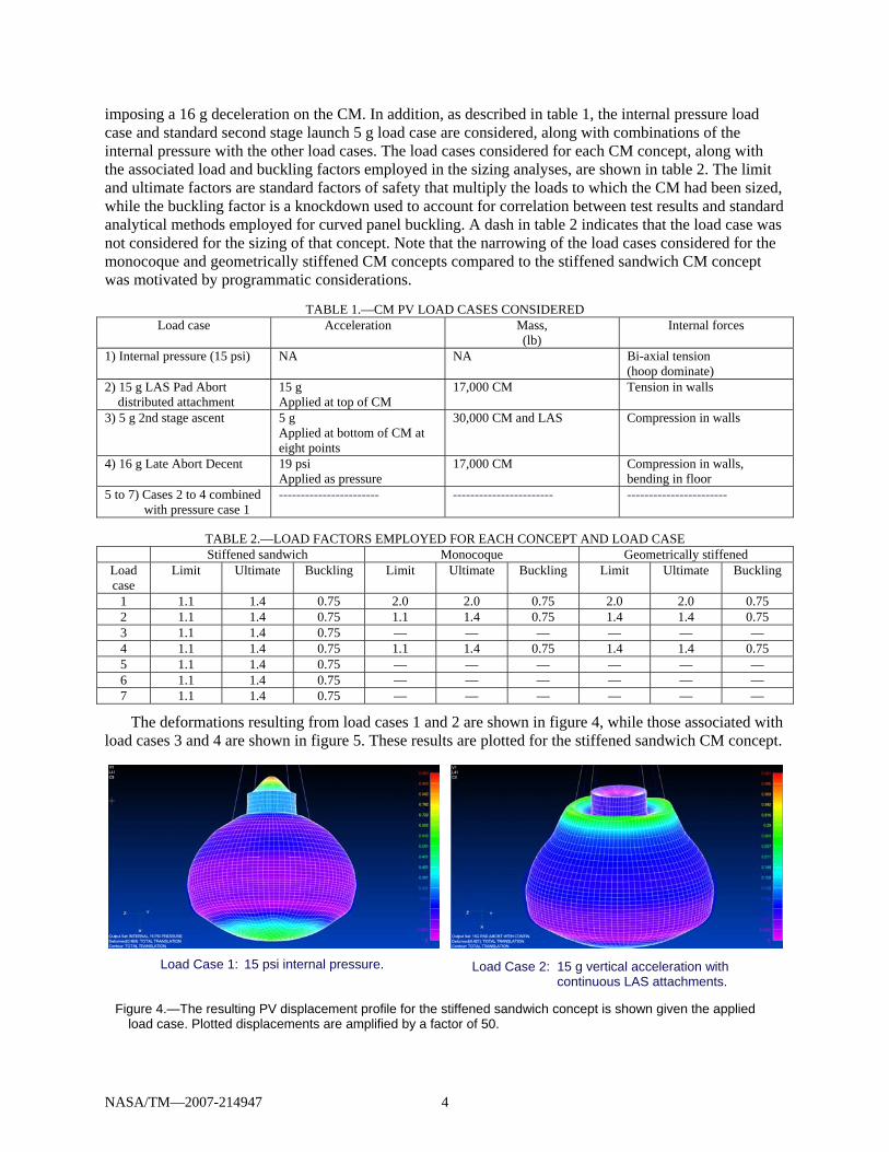
The load cases considered for the CM are shown in figure 3 and summarized in table 1. Highlighted in figure 3 are the 15 g LAS pull-off load that would be used for escape were there an unintended event associated with the rocket stack during launch. The late abort case is also extreme,
Figure 3.—Schematic showing a variety of potential loading scenarios for the CM.
LAS Acceleration LAS Abort Acceleration = 15 g’s (CM Tension)
Late Abort Entry Deceleration = 16 g’s (CM Compression) Heat Shield Loading = 19.74 psi
NASA/TM—2007-214947 4
imposing a 16 g deceleration on the CM. In addition, as described in table 1, the internal pressure load case and standard second stage launch 5 g load case are considered, along with combinations of the internal pressure with the other load cases. The load cases considered for each CM concept, along with the associated load and buckling factors employed in the sizing analyses, are shown in table 2. The limit and ultimate factors are standard factors of safety that multiply the loads to which the CM had been sized, while the buckling factor is a knockdown used to account for correlation between test results and standard analytical methods employed for curved panel buckling. A dash in table 2 indicates that the load case was not considered for the sizing of that concept. Note that the narrowing of the load cases considered for the monocoque and geometrically stiffened CM concepts compared to the stiffened sandwich CM concept was motivated by programmatic considerations.
TABLE 1.—CM PV LOAD CASES CONSIDERED Load case Acceleration Mass,
(lb) Internal forces
1) Internal pressure (15 psi) NA NA Bi-axial tension (hoop dominate)
2) 15 g LAS Pad Abort distributed attachment
15 g Applied at top of CM
17,000 CM Tension in walls
3) 5 g 2nd stage ascent 5 g Applied at bottom of CM at eight points
30,000 CM and LAS Compression in walls
4) 16 g Late Abort Decent 19 psi Applied as pressure
17,000 CM Compression in walls, bending in floor
5 to 7) Cases 2 to 4 combined with pressure case 1
----------------------- ----------------------- -----------------------
TABLE 2.—LOAD FACTORS EMPLOYED FOR EACH CONCEPT AND LOAD CASE
Stiffened sandwich Monocoque Geometrically stiffened Load case
Limit Ultimate Buckling Limit Ultimate Buckling Limit Ultimate Buckling
1 1.1 1.4 0.75 2.0 2.0 0.75 2.0 2.0 0.75 2 1.1 1.4 0.75 1.1 1.4 0.75 1.4 1.4 0.75 3 1.1 1.4 0.75 — — — — — — 4 1.1 1.4 0.75 1.1 1.4 0.75 1.4 1.4 0.75 5 1.1 1.4 0.75 — — — — — — 6 1.1 1.4 0.75 — — — — — — 7 1.1 1.4 0.75 — — — — — —
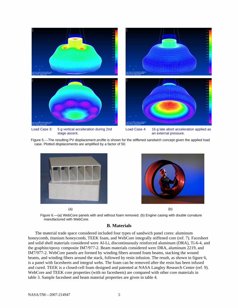
The deformations resulting from load cases 1 and 2 are shown in figure 4, while those associated with load cases 3 and 4 are shown in figure 5. These results are plotted for the stiffened sandwich CM concept.
Figure 4.—The resulting PV displacement profile for the stiffened sandwich concept is shown given the applied
load case. Plotted displacements are amplified by a factor of 50.
Load Case 1: 15 psi internal pressure. Load Case 2: 15 g vertical acceleration with continuous LAS attachments.
NASA/TM—2007-214947 5
(a) (b)
Figure 6.—(a) WebCore panels with and without foam removed. (b) Engine casing with double curvature manufactured with WebCore.
B. Materials The material trade space considered included four types of sandwich panel cores: aluminum
honeycomb, titanium honeycomb, TEEK foam, and WebCore integrally stiffened core (ref. 7). Facesheet and solid shell materials considered were Al-Li, discontinuously reinforced aluminum (DRA), Ti-6-4, and the graphite/epoxy composite IM7/977-2. Beam materials considered were DRA, aluminum 2219, and IM7/977-2. WebCore panels are formed by winding fibers around foam beams, stacking the wound beams, and winding fibers around the stack, followed by resin infusion. The result, as shown in figure 6, is a panel with facesheets and integral webs. The foam can be removed after the resin has been infused and cured. TEEK is a closed-cell foam designed and patented at NASA Langley Research Center (ref. 9). WebCore and TEEK core properties (with no facesheets) are compared with other core materials in table 3. Sample facesheet and beam material properties are given in table 4.
Figure 5.—The resulting PV displacement profile is shown for the stiffened sandwich concept given the applied load case. Plotted displacements are amplified by a factor of 50.
Load Case 3: 5 g vertical acceleration during 2nd stage ascent.
Load Case 4: 16 g late abort acceleration applied as an external pressure.
NASA/TM—2007-214947 6
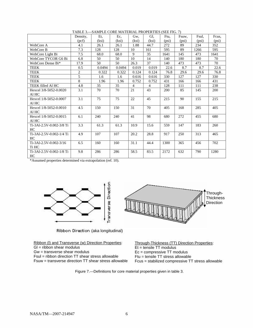
TABLE 3.—SAMPLE CORE MATERIAL PROPERTIES (SEE FIG. 7) Density,
(pcf) Et,
(ksi) Ec,
(ksi) Gw, (ksi)
Gl, (ksi)
Ftu, (psi)
Fsuw, (psi)
Fsul, (psi)
Fcus, (psi)
WebCore A 4.1 26.1 26.1 1.88 44.7 272 89 234 352 WebCore B 7.3 128 128 10 161 595 89 1266 595 WebCore Light Bi 7.5 68.0 68.0 9 35 1641 145 473 1641 WebCore TYCOR G6 Bi 6.8 50 50 10 14 140 180 180 70 WebCore Dense Bi* 17.9 50 50 26.3 37 140 473 473 70 TEEK 0.5 0.0494 0.0494 0.019 0.019 22.6 8.7 8.7 22.6 TEEK 2 0.322 0.322 0.124 0.124 76.8 29.6 29.6 76.8 TEEK 5 1.6 1.6 0.616 0.616 330 127 127 330 TEEK 8 1.96 1.96 0.752 0.752 431 166 166 431 TEEK filled Al HC 4.8 35 35 4 4 128 111 111 238 Hexcel 3/8-5052-0.0020 Al HC
3.1 70 70 21 43 200 85 145 200
Hexcel 1/8-5052-0.0007 Al HC
3.1 75 75 22 45 215 90 155 215
Hexcel 1/8-5052-0.0010 Al HC
4.5 150 150 31 70 405 168 285 405
Hexcel 1/8-5052-0.0015 Al HC
6.1 240 240 41 98 680 272 455 680
Ti-3Al-2.5V-0.002-3/8 Ti HC
3.3 61.3 61.3 10.9 15.6 559 147 183 260
Ti-3Al-2.5V-0.002-1/4 Ti HC
4.9 107 107 20.2 28.8 917 250 313 465
Ti-3Al-2.5V-0.002-3/16 Ti HC
6.5 160 160 31.1 44.4 1300 365 456 702
Ti-3Al-2.5V-0.002-1/8 Ti HC
9.8 286 286 58.5 83.5 2172 632 790 1280
*Assumed properties determined via extrapolation (ref. 10).
Through-Thickness (TT) Direction Properties: Et = tensile TT modulus Ec = compressive TT modulus Ftu = tensile TT stress allowable Fcus = stabilized compressive TT stress allowable
Ribbon (l) and Transverse (w) Direction Properties: Gl = ribbon shear modulus Gw = transverse shear modulus Fsul = ribbon direction TT shear stress allowable Fsuw = transverse direction TT shear stress allowable
Figure 7.—Definitions for core material properties given in table 3.
Through-Thickness Direction
(aka longitudinal)
NASA/TM—2007-214947 7
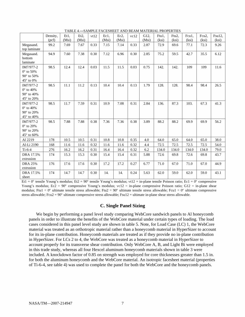
TABLE 4.—SAMPLE FACESHEET AND BEAM MATERIAL PROPERTIES Density,
(pcf) Et1,
(Msi) Et2,
(Msi) νt12 Ec1,
(Msi) Ec2, (Msi)
νc12 G12, (Msi)
Ftu1, (ksi)
Ftu2, (ksi)
Fcu1, (ksi)
Fcu2, (ksi)
Fsu12, (ksi)
Megasand. top laminate
99.2 7.69 7.67 0.33 7.15 7.14 0.33 2.87 72.9 69.6 77.1 72.3 9.26
Megasand. bottom laminate
94.9 7.60 7.38 0.30 7.12 6.96 0.30 2.85 75.2 59.5 42.7 35.5 6.12
IM7/977-2 0° to 50% 90° to 50% 45° to 0%
98.5 12.4 12.4 0.03 11.5 11.5 0.03 0.75 142. 142. 109 109 11.6
IM7/977-2 0° to 40% 90° to 40% 45° to 20%
98.5 11.1 11.2 0.13 10.4 10.4 0.13 1.79 128. 128. 98.4 98.4 26.5
IM7/977-2 0° to 40% 90° to 20% 45° to 40%
98.5 11.7 7.59 0.31 10.9 7.08 0.31 2.84 136. 87.3 103. 67.3 41.3
IM7/977-2 0° to 20% 90° to 20% 45° to 60%
98.5 7.88 7.88 0.38 7.36 7.36 0.38 3.89 88.2 88.2 69.9 69.9 56.2
Al 2219 178 10.5 10.5 0.31 10.8 10.8 0.35 4.0 64.0 65.0 64.0 65.0 38.0 Al-Li 2190 168 11.6 11.6 0.32 11.6 11.6 0.32 4.4 72.5 72.5 72.5 72.5 54.0 Ti-6-4 276 16.2 16.2 0.31 16.4 16.4 0.32 6.2 134.0 134.0 134.0 134.0 79.0 DRA 17.5% extrusion
174 15.3 15.3 0.30 15.4 15.4 0.31 5.88 72.6 69.8 72.6 69.8 43.7
DRA 25% extrusion
176 17.6 17.6 0.30 17.2 17.2 0.27 6.77 71.0 67.0 71.0 67.0 44.9
DRA 17.5% sheet
174 14.7 14.7 0.30 14. 14. 0.24 5.63 62.0 59.0 62.0 59.0 43.1
Et1 = 0° tensile Young’s modulus; Et2 = 90° tensile Young’s modulus; νt12 = in-plane tensile Poisson ratio; Ec1 = 0° compressive Young’s modulus; Ec2 = 90° compressive Young’s modulus; νc12 = in-plane compressive Poisson ratio; G12 = in-plane shear modulus; Ftu1 = 0° ultimate tensile stress allowable; Ftu2 = 90° ultimate tensile stress allowable; Fcu1 = 0° ultimate compressive stress allowable; Fcu2 = 90° ultimate compressive stress allowable; Fsu12 = ultimate in-plane shear stress allowable.
C. Single Panel Sizing
We begin by performing a panel level study comparing WebCore sandwich panels to Al honeycomb panels in order to illustrate the benefits of the WebCore material under certain types of loading. The load cases considered in this panel level study are shown in table 5. Note, for Load Case (LC) 1, the WebCore material was treated as an orthotropic material rather than a honeycomb material in HyperSizer to account for its in-plane contribution. Honeycomb materials are treated as if they provide no in-plane contribution in HyperSizer. For LCs 2 to 4, the WebCore was treated as a honeycomb material in HyperSizer to account properly for its transverse shear contribution. Only WebCore A, B, and Light Bi were employed in this trade study, whereas all four Hexcel aluminum honeycomb materials shown in table 3 were included. A knockdown factor of 0.85 on strength was employed for core thicknesses greater than 1.5 in. for both the aluminum honeycomb and the WebCore material. An isotropic facesheet material (properties of Ti-6-4, see table 4) was used to complete the panel for both the WebCore and the honeycomb panels.
NASA/TM—2007-214947 8
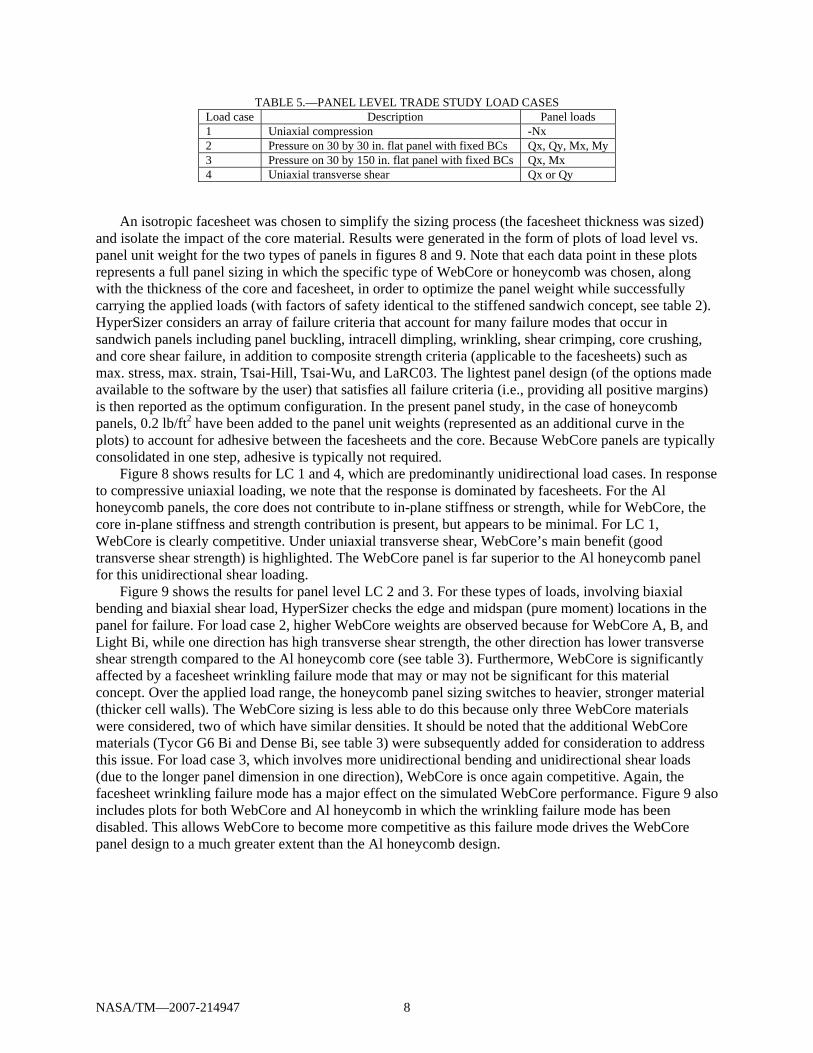
TABLE 5.—PANEL LEVEL TRADE STUDY LOAD CASES Load case Description Panel loads 1 Uniaxial compression -Nx 2 Pressure on 30 by 30 in. flat panel with fixed BCs Qx, Qy, Mx, My 3 Pressure on 30 by 150 in. flat panel with fixed BCs Qx, Mx 4 Uniaxial transverse shear Qx or Qy
An isotropic facesheet was chosen to simplify the sizing process (the facesheet thickness was sized) and isolate the impact of the core material. Results were generated in the form of plots of load level vs. panel unit weight for the two types of panels in figures 8 and 9. Note that each data point in these plots represents a full panel sizing in which the specific type of WebCore or honeycomb was chosen, along with the thickness of the core and facesheet, in order to optimize the panel weight while successfully carrying the applied loads (with factors of safety identical to the stiffened sandwich concept, see table 2). HyperSizer considers an array of failure criteria that account for many failure modes that occur in sandwich panels including panel buckling, intracell dimpling, wrinkling, shear crimping, core crushing, and core shear failure, in addition to composite strength criteria (applicable to the facesheets) such as max. stress, max. strain, Tsai-Hill, Tsai-Wu, and LaRC03. The lightest panel design (of the options made available to the software by the user) that satisfies all failure criteria (i.e., providing all positive margins) is then reported as the optimum configuration. In the present panel study, in the case of honeycomb panels, 0.2 lb/ft2 have been added to the panel unit weights (represented as an additional curve in the plots) to account for adhesive between the facesheets and the core. Because WebCore panels are typically consolidated in one step, adhesive is typically not required.
Figure 8 shows results for LC 1 and 4, which are predominantly unidirectional load cases. In response to compressive uniaxial loading, we note that the response is dominated by facesheets. For the Al honeycomb panels, the core does not contribute to in-plane stiffness or strength, while for WebCore, the core in-plane stiffness and strength contribution is present, but appears to be minimal. For LC 1, WebCore is clearly competitive. Under uniaxial transverse shear, WebCore’s main benefit (good transverse shear strength) is highlighted. The WebCore panel is far superior to the Al honeycomb panel for this unidirectional shear loading.
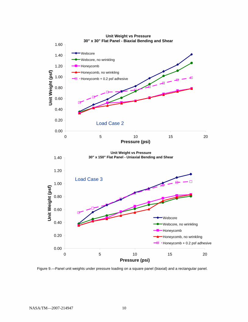
Figure 9 shows the results for panel level LC 2 and 3. For these types of loads, involving biaxial bending and biaxial shear load, HyperSizer checks the edge and midspan (pure moment) locations in the panel for failure. For load case 2, higher WebCore weights are observed because for WebCore A, B, and Light Bi, while one direction has high transverse shear strength, the other direction has lower transverse shear strength compared to the Al honeycomb core (see table 3). Furthermore, WebCore is significantly affected by a facesheet wrinkling failure mode that may or may not be significant for this material concept. Over the applied load range, the honeycomb panel sizing switches to heavier, stronger material (thicker cell walls). The WebCore sizing is less able to do this because only three WebCore materials were considered, two of which have similar densities. It should be noted that the additional WebCore materials (Tycor G6 Bi and Dense Bi, see table 3) were subsequently added for consideration to address this issue. For load case 3, which involves more unidirectional bending and unidirectional shear loads (due to the longer panel dimension in one direction), WebCore is once again competitive. Again, the facesheet wrinkling failure mode has a major effect on the simulated WebCore performance. Figure 9 also includes plots for both WebCore and Al honeycomb in which the wrinkling failure mode has been disabled. This allows WebCore to become more competitive as this failure mode drives the WebCore panel design to a much greater extent than the Al honeycomb design.
NASA/TM—2007-214947 9
Figure 8.—Panel unit weights under uniaxial tension and pure transverse shear loading cases.
Unit Weight vs Uniaxial Load (30" x 30" panel)
0.00
0.50
1.00
1.50
2.00
2.50
3.00
3.50
4.00
4.50
5.00
0 2,000 4,000 6,000 8,000 10,000 12,000 14,000 16,000Compressive Uniaxial Load, Nx (lb/in)
Uni
t Wei
ght (
psf)
Webcore
Honeycomb
Honeycomb + 0.2 psf adhesive
Load Case 1
Load Case 4
Unit Weight vs Transverse Shear30" x 30" Flat Panel
0.00
0.10
0.20
0.30
0.40
0.50
0.60
0.70
0.80
0.90
1.00
0 100 200 300 400 500Q (lb/in)
Uni
t Wei
ght (
psf)
Webcore
Honeycomb
Honeycomb + 0.2 psf adhesive
NASA/TM—2007-214947 10
Figure 9.—Panel unit weights under pressure loading on a square panel (biaxial) and a rectangular panel.
Unit Weight vs Pressure30" x 30" Flat Panel - Biaxial Bending and Shear
0.00
0.20
0.40
0.60
0.80
1.00
1.20
1.40
1.60
0 5 10 15 20Pressure (psi)
Uni
t Wei
ght (
psf)
Webcore
Webcore, no wrinkling
Honeycomb
Honeycomb, no wrinkling
Honeycomb + 0.2 psf adhesive
Unit Weight vs Pressure30" x 150" Flat Panel - Uniaxial Bending and Shear
0.00
0.20
0.40
0.60
0.80
1.00
1.20
1.40
0 5 10 15 20Pressure (psi)
Uni
t Wei
ght (
psf)
Webcore
Webcore, no wrinkling
Honeycomb
Honeycomb, no wrinkling
Honeycomb + 0.2 psf adhesive
Load Case 2
Load Case 3
NASA/TM—2007-214947 11
From this panel level study, it has been observed that, for load cases that are nearly pure unidirectional transverse shear, the WebCore material is far superior to the Al honeycomb. WebCore is at least competitive under other load cases. It is important to consider the (probable) need for adhesive to bond the facesheets to Al honeycomb. This is likely not needed in WebCore as facesheets can be integrally manufactured. Given that WebCore properties can be tailored to specific applications, certain issues can be addressed, including better biaxial performance, improved facesheet wrinkling resistance (requires examination of this failure mode), and a positive linear relationship between performance and weight. In addition, the 0.85 strength knockdown for core thicknesses above 1.5 in. is likely not needed for WebCore, as results have shown that no such strength reduction occurs. Finally, it should be noted that pristine material properties have been used in this panel level study. Were knocked down properties used to account for the presence of damage, it is likely that WebCore’s performance would have improved as WebCore has been shown to exhibit excellent damage tolerance. For these reasons, this single panel study should be considered as a worst case scenario for WebCore in its comparison with aluminum honeycomb.
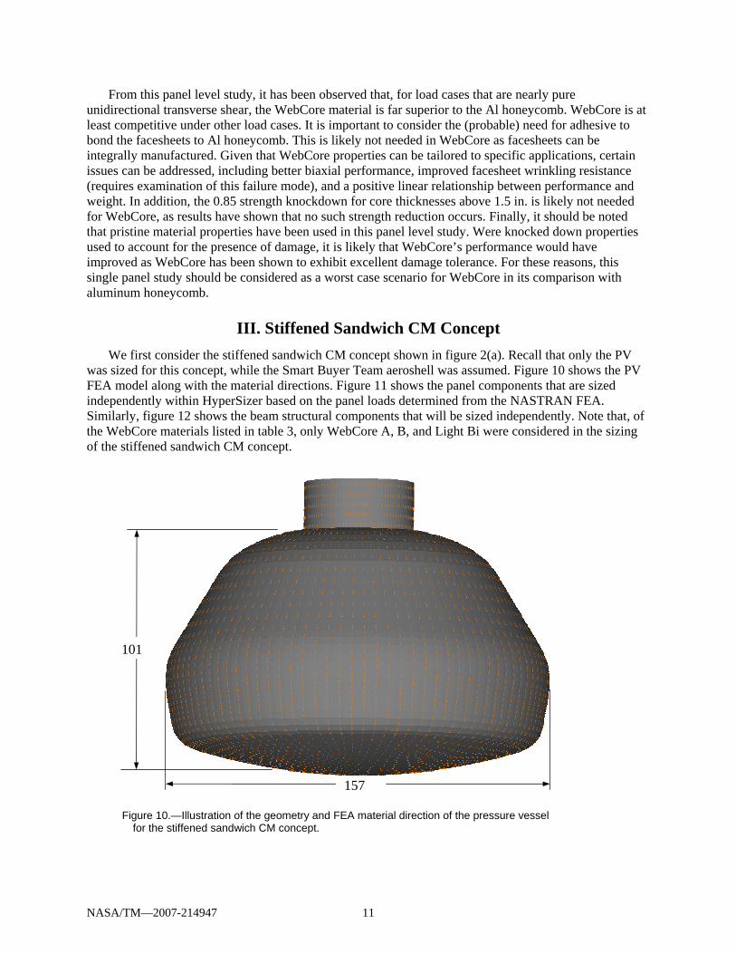
III. Stiffened Sandwich CM Concept We first consider the stiffened sandwich CM concept shown in figure 2(a). Recall that only the PV
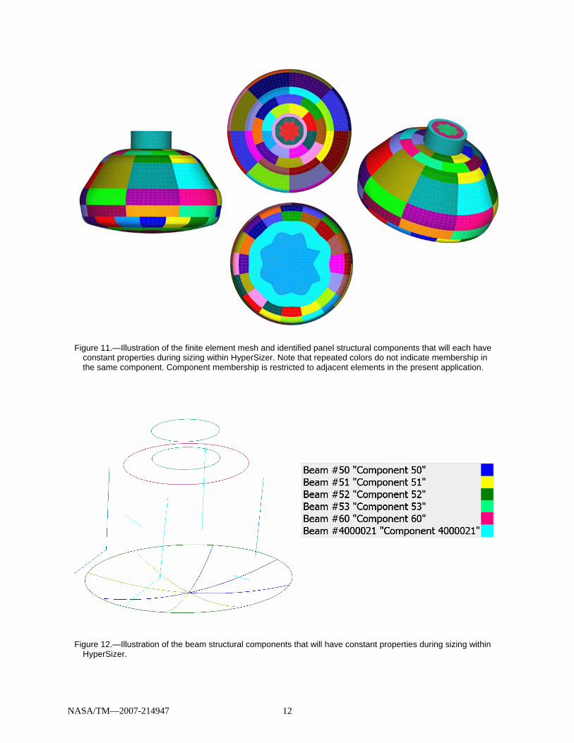
was sized for this concept, while the Smart Buyer Team aeroshell was assumed. Figure 10 shows the PV FEA model along with the material directions. Figure 11 shows the panel components that are sized independently within HyperSizer based on the panel loads determined from the NASTRAN FEA. Similarly, figure 12 shows the beam structural components that will be sized independently. Note that, of the WebCore materials listed in table 3, only WebCore A, B, and Light Bi were considered in the sizing of the stiffened sandwich CM concept.
101
157
Figure 10.—Illustration of the geometry and FEA material direction of the pressure vessel for the stiffened sandwich CM concept.
NASA/TM—2007-214947 12
Figure 12.—Illustration of the beam structural components that will have constant properties during sizing within HyperSizer.
Figure 11.—Illustration of the finite element mesh and identified panel structural components that will each have constant properties during sizing within HyperSizer. Note that repeated colors do not indicate membership in the same component. Component membership is restricted to adjacent elements in the present application.
NASA/TM—2007-214947 13
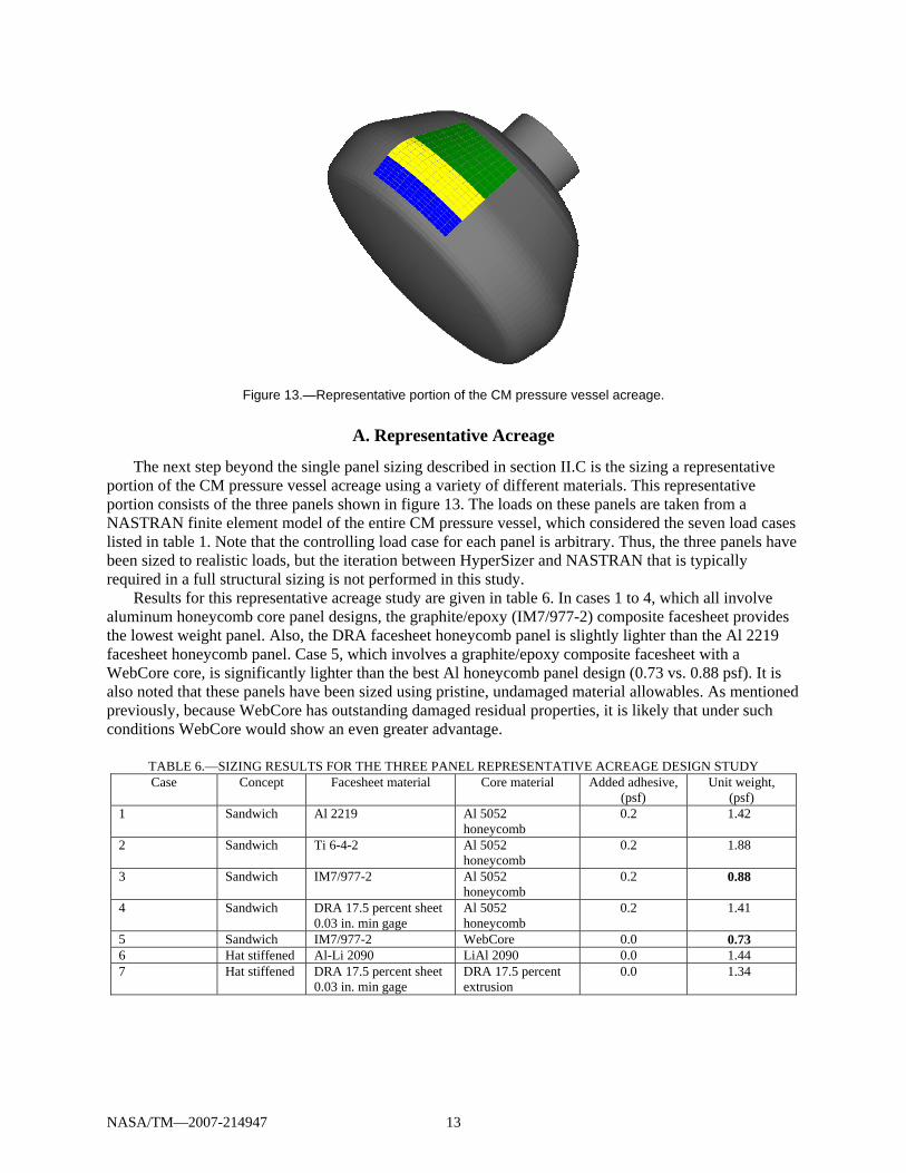
Figure 13.—Representative portion of the CM pressure vessel acreage.
A. Representative Acreage
The next step beyond the single panel sizing described in section II.C is the sizing a representative portion of the CM pressure vessel acreage using a variety of different materials. This representative portion consists of the three panels shown in figure 13. The loads on these panels are taken from a NASTRAN finite element model of the entire CM pressure vessel, which considered the seven load cases listed in table 1. Note that the controlling load case for each panel is arbitrary. Thus, the three panels have been sized to realistic loads, but the iteration between HyperSizer and NASTRAN that is typically required in a full structural sizing is not performed in this study.
Results for this representative acreage study are given in table 6. In cases 1 to 4, which all involve aluminum honeycomb core panel designs, the graphite/epoxy (IM7/977-2) composite facesheet provides the lowest weight panel. Also, the DRA facesheet honeycomb panel is slightly lighter than the Al 2219 facesheet honeycomb panel. Case 5, which involves a graphite/epoxy composite facesheet with a WebCore core, is significantly lighter than the best Al honeycomb panel design (0.73 vs. 0.88 psf). It is also noted that these panels have been sized using pristine, undamaged material allowables. As mentioned previously, because WebCore has outstanding damaged residual properties, it is likely that under such conditions WebCore would show an even greater advantage.
TABLE 6.—SIZING RESULTS FOR THE THREE PANEL REPRESENTATIVE ACREAGE DESIGN STUDY Case Concept Facesheet material Core material Added adhesive,
(psf) Unit weight,
(psf) 1 Sandwich Al 2219 Al 5052
honeycomb 0.2 1.42
2 Sandwich Ti 6-4-2 Al 5052 honeycomb
0.2 1.88
3 Sandwich IM7/977-2 Al 5052 honeycomb
0.2 0.88
4 Sandwich DRA 17.5 percent sheet 0.03 in. min gage
Al 5052 honeycomb
0.2 1.41
5 Sandwich IM7/977-2 WebCore 0.0 0.73 6 Hat stiffened Al-Li 2090 LiAl 2090 0.0 1.44 7 Hat stiffened DRA 17.5 percent sheet
0.03 in. min gage DRA 17.5 percent extrusion
0.0 1.34
NASA/TM—2007-214947 14
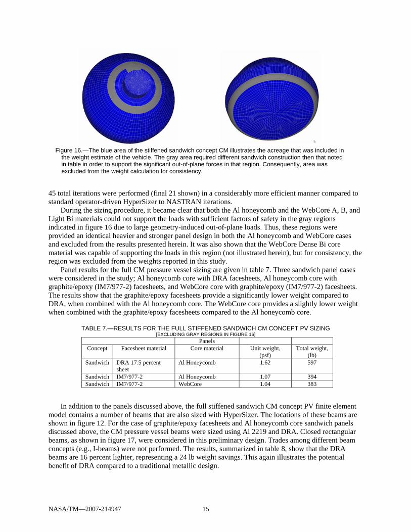
Figure 15.—In this HyperFEA interface, 21 iterations are shown between HyperSizer and NASTRAN FEA. Red = beam weight; Green = panel weight; Blue = total weight. Large discontinuous changes represent a change in HyperSizer data, such as adding/removing materials from consideration in the design.
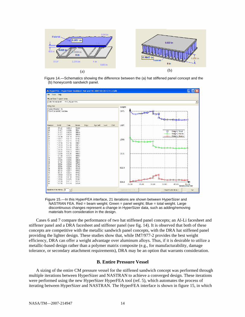
Cases 6 and 7 compare the performance of two hat stiffened panel concepts; an Al-Li facesheet and
stiffener panel and a DRA facesheet and stiffener panel (see fig. 14). It is observed that both of these concepts are competitive with the metallic sandwich panel concepts, with the DRA hat stiffened panel providing the lighter design. These studies show that, while IM7/977-2 provides the best weight efficiency, DRA can offer a weight advantage over aluminum alloys. Thus, if it is desirable to utilize a metallic-based design rather than a polymer matrix composite (e.g., for manufacturability, damage tolerance, or secondary attachment requirements), DRA may be an option that warrants consideration.
B. Entire Pressure Vessel
A sizing of the entire CM pressure vessel for the stiffened sandwich concept was performed through multiple iterations between HyperSizer and NASTRAN to achieve a converged design. These iterations were performed using the new HyperSizer HyperFEA tool (ref. 5), which automates the process of iterating between HyperSizer and NASTRAN. The HyperFEA interface is shown in figure 15, in which
Figure 14.—Schematics showing the difference between the (a) hat stiffened panel concept and the (b) honeycomb sandwich panel.
(a) (b)
NASA/TM—2007-214947 15
45 total iterations were performed (final 21 shown) in a considerably more efficient manner compared to standard operator-driven HyperSizer to NASTRAN iterations.
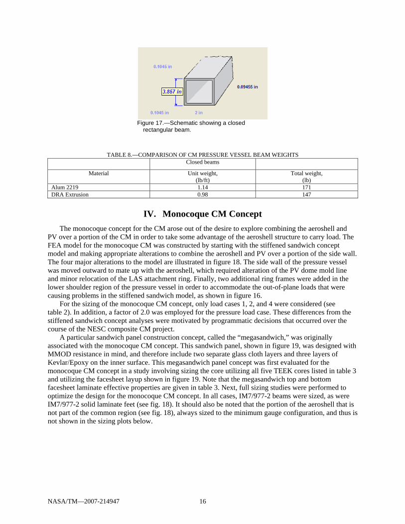
During the sizing procedure, it became clear that both the Al honeycomb and the WebCore A, B, and Light Bi materials could not support the loads with sufficient factors of safety in the gray regions indicated in figure 16 due to large geometry-induced out-of-plane loads. Thus, these regions were provided an identical heavier and stronger panel design in both the Al honeycomb and WebCore cases and excluded from the results presented herein. It was also shown that the WebCore Dense Bi core material was capable of supporting the loads in this region (not illustrated herein), but for consistency, the region was excluded from the weights reported in this study.
Panel results for the full CM pressure vessel sizing are given in table 7. Three sandwich panel cases were considered in the study; Al honeycomb core with DRA facesheets, Al honeycomb core with graphite/epoxy (IM7/977-2) facesheets, and WebCore core with graphite/epoxy (IM7/977-2) facesheets. The results show that the graphite/epoxy facesheets provide a significantly lower weight compared to DRA, when combined with the Al honeycomb core. The WebCore core provides a slightly lower weight when combined with the graphite/epoxy facesheets compared to the Al honeycomb core.
TABLE 7.—RESULTS FOR THE FULL STIFFENED SANDWICH CM CONCEPT PV SIZING [EXCLUDING GRAY REGIONS IN FIGURE 16]
Panels Concept Facesheet material Core material Unit weight,
(psf) Total weight,
(lb) Sandwich DRA 17.5 percent
sheet Al Honeycomb 1.62 597
Sandwich IM7/977-2 Al Honeycomb 1.07 394 Sandwich IM7/977-2 WebCore 1.04 383
In addition to the panels discussed above, the full stiffened sandwich CM concept PV finite element
model contains a number of beams that are also sized with HyperSizer. The locations of these beams are shown in figure 12. For the case of graphite/epoxy facesheets and Al honeycomb core sandwich panels discussed above, the CM pressure vessel beams were sized using Al 2219 and DRA. Closed rectangular beams, as shown in figure 17, were considered in this preliminary design. Trades among different beam concepts (e.g., I-beams) were not performed. The results, summarized in table 8, show that the DRA beams are 16 percent lighter, representing a 24 lb weight savings. This again illustrates the potential benefit of DRA compared to a traditional metallic design.
Figure 16.—The blue area of the stiffened sandwich concept CM illustrates the acreage that was included in the weight estimate of the vehicle. The gray area required different sandwich construction then that noted in table in order to support the significant out-of-plane forces in that region. Consequently, area was excluded from the weight calculation for consistency.
NASA/TM—2007-214947 16
Figure 17.—Schematic showing a closed
rectangular beam.
TABLE 8.—COMPARISON OF CM PRESSURE VESSEL BEAM WEIGHTS Closed beams
Material Unit weight, (lb/ft)
Total weight, (lb)
Alum 2219 1.14 171 DRA Extrusion 0.98 147
IV. Monocoque CM Concept The monocoque concept for the CM arose out of the desire to explore combining the aeroshell and
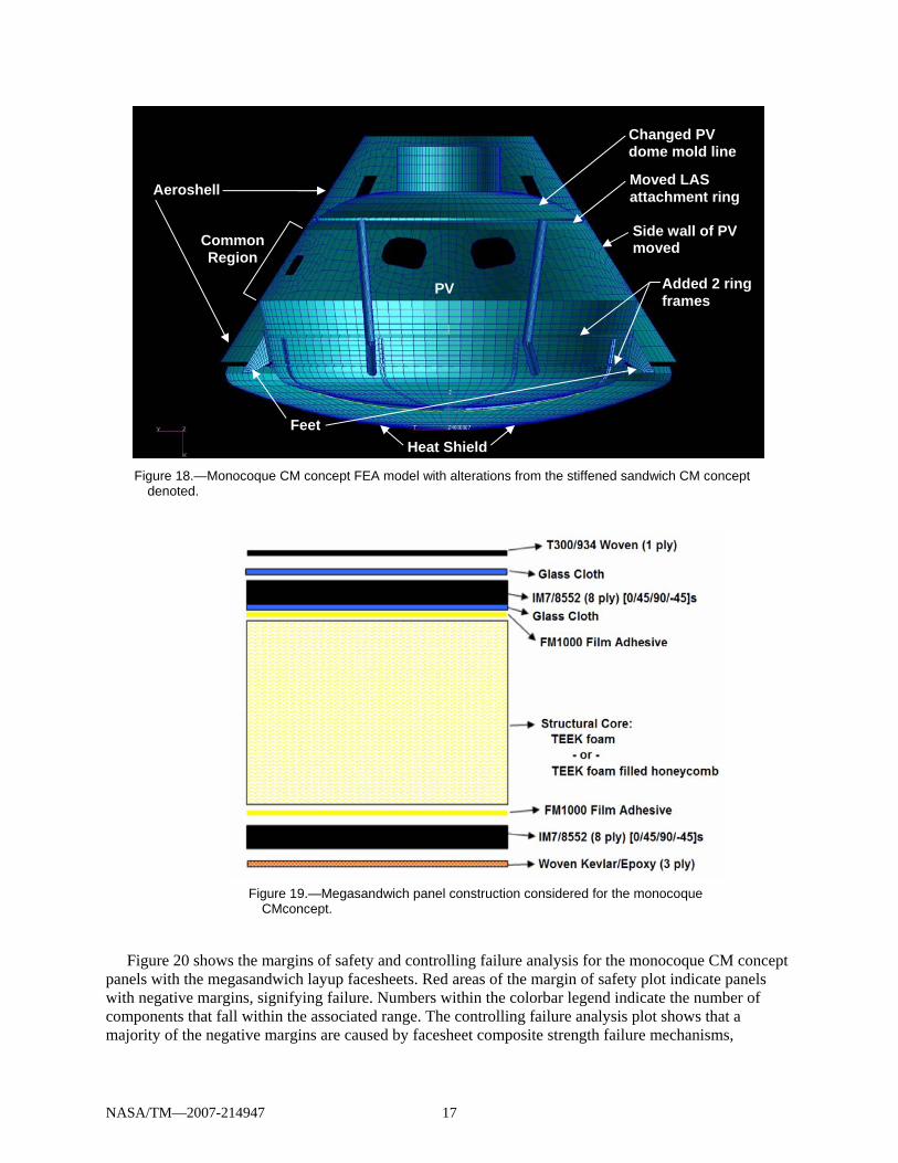
PV over a portion of the CM in order to take some advantage of the aeroshell structure to carry load. The FEA model for the monocoque CM was constructed by starting with the stiffened sandwich concept model and making appropriate alterations to combine the aeroshell and PV over a portion of the side wall. The four major alterations to the model are illustrated in figure 18. The side wall of the pressure vessel was moved outward to mate up with the aeroshell, which required alteration of the PV dome mold line and minor relocation of the LAS attachment ring. Finally, two additional ring frames were added in the lower shoulder region of the pressure vessel in order to accommodate the out-of-plane loads that were causing problems in the stiffened sandwich model, as shown in figure 16.
For the sizing of the monocoque CM concept, only load cases 1, 2, and 4 were considered (see table 2). In addition, a factor of 2.0 was employed for the pressure load case. These differences from the stiffened sandwich concept analyses were motivated by programmatic decisions that occurred over the course of the NESC composite CM project.
A particular sandwich panel construction concept, called the “megasandwich,” was originally associated with the monocoque CM concept. This sandwich panel, shown in figure 19, was designed with MMOD resistance in mind, and therefore include two separate glass cloth layers and three layers of Kevlar/Epoxy on the inner surface. This megasandwich panel concept was first evaluated for the monocoque CM concept in a study involving sizing the core utilizing all five TEEK cores listed in table 3 and utilizing the facesheet layup shown in figure 19. Note that the megasandwich top and bottom facesheet laminate effective properties are given in table 3. Next, full sizing studies were performed to optimize the design for the monocoque CM concept. In all cases, IM7/977-2 beams were sized, as were IM7/977-2 solid laminate feet (see fig. 18). It should also be noted that the portion of the aeroshell that is not part of the common region (see fig. 18), always sized to the minimum gauge configuration, and thus is not shown in the sizing plots below.
NASA/TM—2007-214947 17
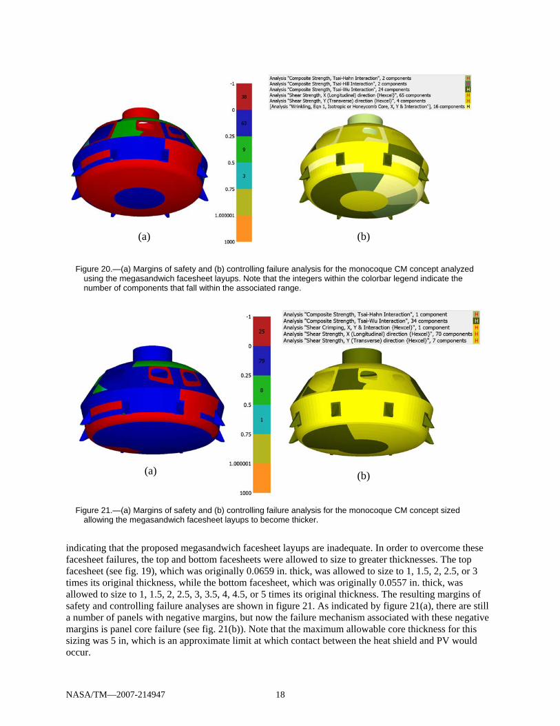
Figure 20 shows the margins of safety and controlling failure analysis for the monocoque CM concept panels with the megasandwich layup facesheets. Red areas of the margin of safety plot indicate panels with negative margins, signifying failure. Numbers within the colorbar legend indicate the number of components that fall within the associated range. The controlling failure analysis plot shows that a majority of the negative margins are caused by facesheet composite strength failure mechanisms,
Figure 19.—Megasandwich panel construction considered for the monocoque CMconcept.
Figure 18.—Monocoque CM concept FEA model with alterations from the stiffened sandwich CM concept denoted.
Heat Shield
Aeroshell
Common Region
PV
Changed PV dome mold line Moved LAS attachment ring
Added 2 ring frames
Side wall of PV moved
Feet
NASA/TM—2007-214947 18
indicating that the proposed megasandwich facesheet layups are inadequate. In order to overcome these facesheet failures, the top and bottom facesheets were allowed to size to greater thicknesses. The top facesheet (see fig. 19), which was originally 0.0659 in. thick, was allowed to size to 1, 1.5, 2, 2.5, or 3 times its original thickness, while the bottom facesheet, which was originally 0.0557 in. thick, was allowed to size to 1, 1.5, 2, 2.5, 3, 3.5, 4, 4.5, or 5 times its original thickness. The resulting margins of safety and controlling failure analyses are shown in figure 21. As indicated by figure 21(a), there are still a number of panels with negative margins, but now the failure mechanism associated with these negative margins is panel core failure (see fig. 21(b)). Note that the maximum allowable core thickness for this sizing was 5 in, which is an approximate limit at which contact between the heat shield and PV would occur.
Figure 21.—(a) Margins of safety and (b) controlling failure analysis for the monocoque CM concept sized allowing the megasandwich facesheet layups to become thicker.
(a) (b)
Figure 20.—(a) Margins of safety and (b) controlling failure analysis for the monocoque CM concept analyzed using the megasandwich facesheet layups. Note that the integers within the colorbar legend indicate the number of components that fall within the associated range.
(a) (b)
NASA/TM—2007-214947 19
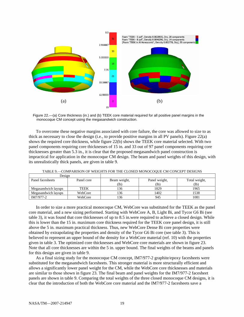
To overcome these negative margins associated with core failure, the core was allowed to size to as
thick as necessary to close the design (i.e., to provide positive margins in all PV panels). Figure 22(a) shows the required core thickness, while figure 22(b) shows the TEEK core material selected. With two panel components requiring core thicknesses of 15 in. and 33 out of 97 panel components requiring core thicknesses greater than 5.3 in., it is clear that the proposed megasandwich panel construction is impractical for application in the monocoque CM design. The beam and panel weights of this design, with its unrealistically thick panels, are given in table 9.
TABLE 9.—COMPARISON OF WEIGHTS FOR THE CLOSED MONOCOQUE CM CONCEPT DESIGNS Design
Panel facesheets Panel core Beam weight, (lb)
Panel weight, (lb)
Total weight, (lb)
Megasandwich layups TEEK 136 1829 1965 Megasandwich layups WebCore 136 1402 1538 IM7/977-2 WebCore 136 945 1081
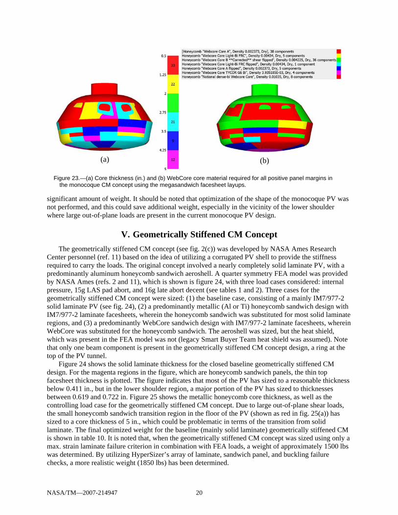
In order to size a more practical monocoque CM, WebCore was substituted for the TEEK as the panel
core material, and a new sizing performed. Starting with WebCore A, B, Light Bi, and Tycor G6 Bi (see table 3), it was found that core thicknesses of up to 8.5 in.were required to achieve a closed design. While this is lower than the 15 in. maximum core thickness required for the TEEK core panel design, it is still above the 5 in. maximum practical thickness. Thus, new WebCore Dense Bi core properties were obtained by extrapolating the properties and density of the Tycor G6 Bi core (see table 3). This is believed to represent an upper bound of the density for a WebCore material (ref. 10) with the properties given in table 3. The optimized core thicknesses and WebCore core materials are shown in figure 23. Note that all core thicknesses are within the 5 in. upper bound. The final weights of the beams and panels for this design are given in table 9.
As a final sizing study for the monocoque CM concept, IM7/977-2 graphite/epoxy facesheets were substituted for the megasandwich facesheets. This stronger material is more structurally efficient and allows a significantly lower panel weight for the CM, while the WebCore core thicknesses and materials are similar to those shown in figure 23. The final beam and panel weights for the IM7/977-2 facesheet panels are shown in table 9. Comparing the total weights of the three closed monocoque CM designs, it is clear that the introduction of both the WebCore core material and the IM7/977-2 facesheets save a
Figure 22.—(a) Core thickness (in.) and (b) TEEK core material required for all positive panel margins in the monocoque CM concept using the megasandwich construction.
(a) (b)
NASA/TM—2007-214947 20
significant amount of weight. It should be noted that optimization of the shape of the monocoque PV was not performed, and this could save additional weight, especially in the vicinity of the lower shoulder where large out-of-plane loads are present in the current monocoque PV design.
V. Geometrically Stiffened CM Concept The geometrically stiffened CM concept (see fig. 2(c)) was developed by NASA Ames Research
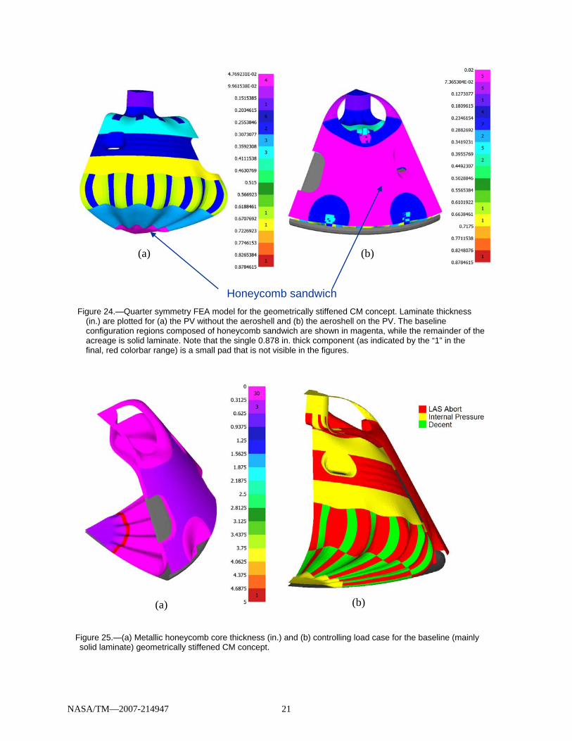
Center personnel (ref. 11) based on the idea of utilizing a corrugated PV shell to provide the stiffness required to carry the loads. The original concept involved a nearly completely solid laminate PV, with a predominantly aluminum honeycomb sandwich aeroshell. A quarter symmetry FEA model was provided by NASA Ames (refs. 2 and 11), which is shown is figure 24, with three load cases considered: internal pressure, 15g LAS pad abort, and 16g late abort decent (see tables 1 and 2). Three cases for the geometrically stiffened CM concept were sized: (1) the baseline case, consisting of a mainly IM7/977-2 solid laminate PV (see fig. 24), (2) a predominantly metallic (Al or Ti) honeycomb sandwich design with IM7/977-2 laminate facesheets, wherein the honeycomb sandwich was substituted for most solid laminate regions, and (3) a predominantly WebCore sandwich design with IM7/977-2 laminate facesheets, wherein WebCore was substituted for the honeycomb sandwich. The aeroshell was sized, but the heat shield, which was present in the FEA model was not (legacy Smart Buyer Team heat shield was assumed). Note that only one beam component is present in the geometrically stiffened CM concept design, a ring at the top of the PV tunnel.
Figure 24 shows the solid laminate thickness for the closed baseline geometrically stiffened CM design. For the magenta regions in the figure, which are honeycomb sandwich panels, the thin top facesheet thickness is plotted. The figure indicates that most of the PV has sized to a reasonable thickness below 0.411 in., but in the lower shoulder region, a major portion of the PV has sized to thicknesses between 0.619 and 0.722 in. Figure 25 shows the metallic honeycomb core thickness, as well as the controlling load case for the geometrically stiffened CM concept. Due to large out-of-plane shear loads, the small honeycomb sandwich transition region in the floor of the PV (shown as red in fig. 25(a)) has sized to a core thickness of 5 in., which could be problematic in terms of the transition from solid laminate. The final optimized weight for the baseline (mainly solid laminate) geometrically stiffened CM is shown in table 10. It is noted that, when the geometrically stiffened CM concept was sized using only a max. strain laminate failure criterion in combination with FEA loads, a weight of approximately 1500 lbs was determined. By utilizing HyperSizer’s array of laminate, sandwich panel, and buckling failure checks, a more realistic weight (1850 lbs) has been determined.
Figure 23.—(a) Core thickness (in.) and (b) WebCore core material required for all positive panel margins in the monocoque CM concept using the megasandwich facesheet layups.
(a) (b)
NASA/TM—2007-214947 21
Figure 25.—(a) Metallic honeycomb core thickness (in.) and (b) controlling load case for the baseline (mainly solid laminate) geometrically stiffened CM concept.
(a) (b)
Figure 24.—Quarter symmetry FEA model for the geometrically stiffened CM concept. Laminate thickness (in.) are plotted for (a) the PV without the aeroshell and (b) the aeroshell on the PV. The baseline configuration regions composed of honeycomb sandwich are shown in magenta, while the remainder of the acreage is solid laminate. Note that the single 0.878 in. thick component (as indicated by the “1” in the final, red colorbar range) is a small pad that is not visible in the figures.
Honeycomb sandwich
(a) (b)
NASA/TM—2007-214947 22
When metallic honeycomb sandwich panels are substituted for the solid laminate PV acreage, the
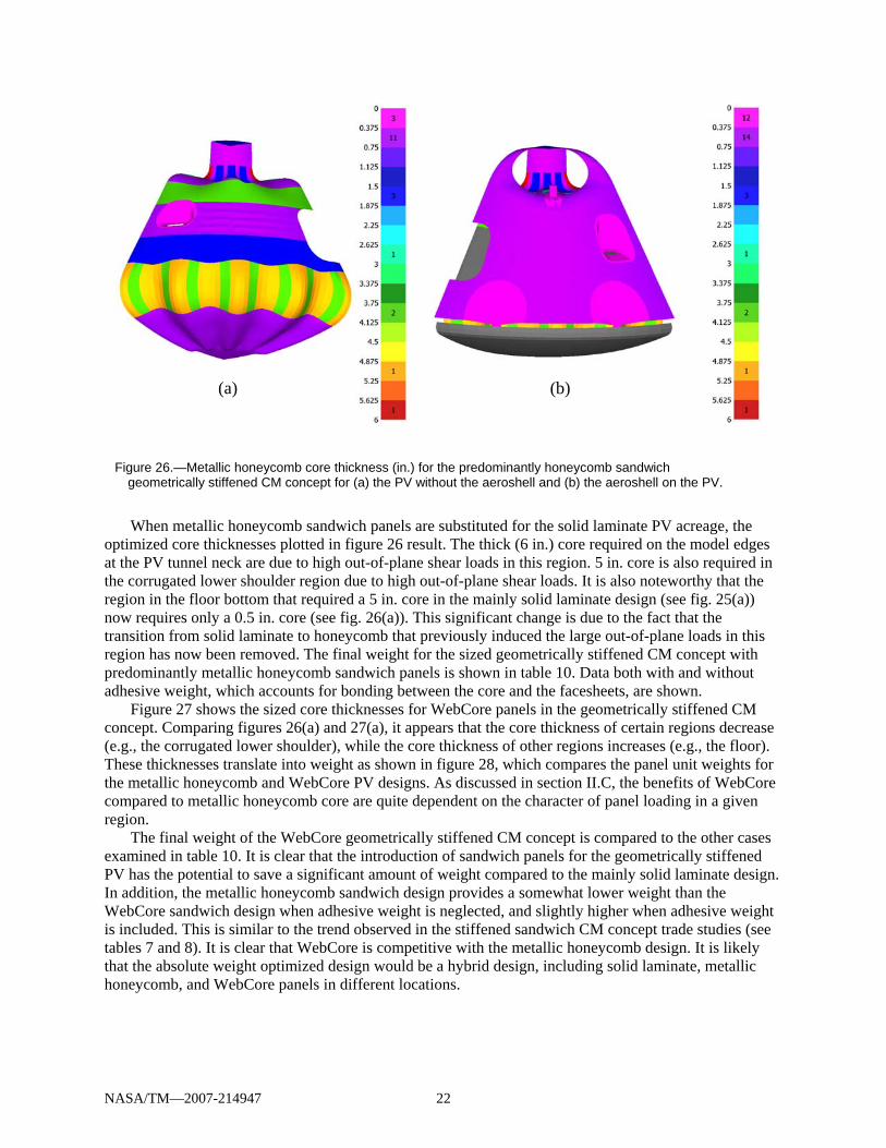
optimized core thicknesses plotted in figure 26 result. The thick (6 in.) core required on the model edges at the PV tunnel neck are due to high out-of-plane shear loads in this region. 5 in. core is also required in the corrugated lower shoulder region due to high out-of-plane shear loads. It is also noteworthy that the region in the floor bottom that required a 5 in. core in the mainly solid laminate design (see fig. 25(a)) now requires only a 0.5 in. core (see fig. 26(a)). This significant change is due to the fact that the transition from solid laminate to honeycomb that previously induced the large out-of-plane loads in this region has now been removed. The final weight for the sized geometrically stiffened CM concept with predominantly metallic honeycomb sandwich panels is shown in table 10. Data both with and without adhesive weight, which accounts for bonding between the core and the facesheets, are shown.
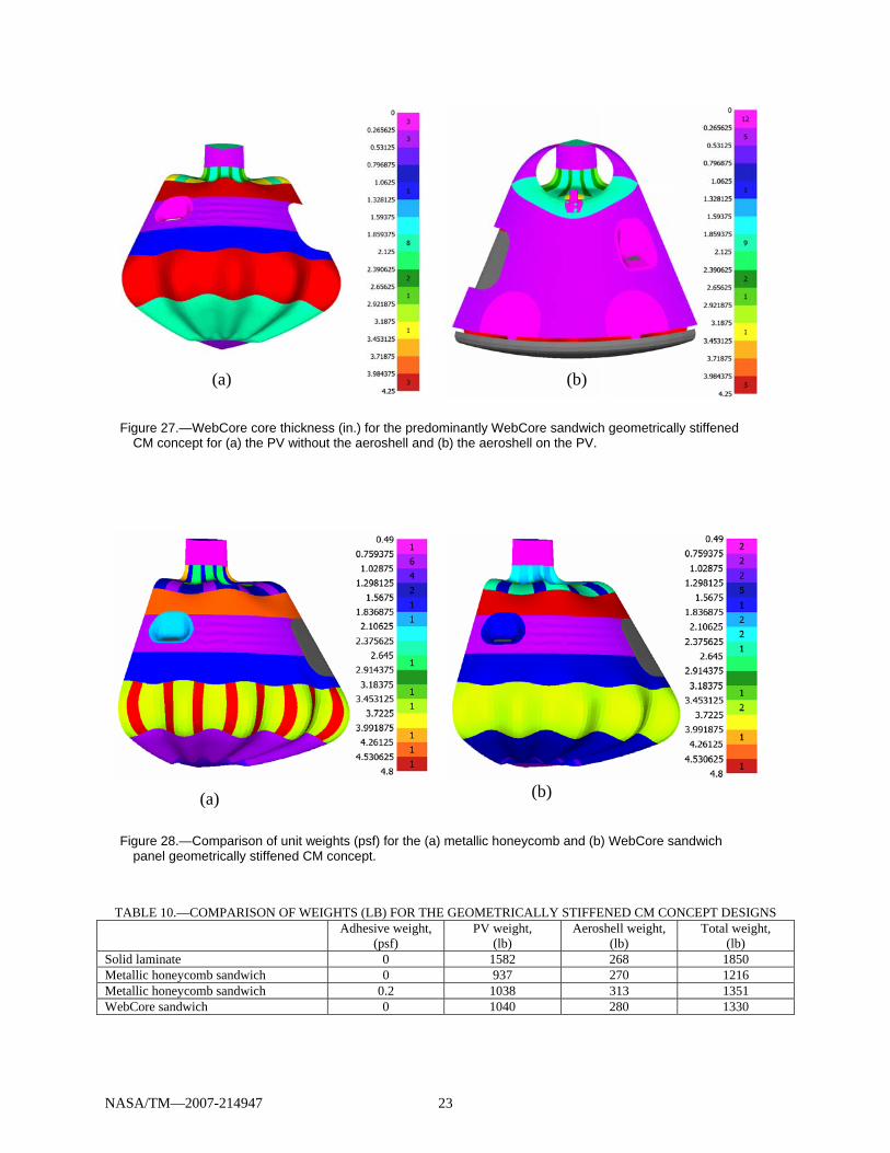
Figure 27 shows the sized core thicknesses for WebCore panels in the geometrically stiffened CM concept. Comparing figures 26(a) and 27(a), it appears that the core thickness of certain regions decrease (e.g., the corrugated lower shoulder), while the core thickness of other regions increases (e.g., the floor). These thicknesses translate into weight as shown in figure 28, which compares the panel unit weights for the metallic honeycomb and WebCore PV designs. As discussed in section II.C, the benefits of WebCore compared to metallic honeycomb core are quite dependent on the character of panel loading in a given region.
The final weight of the WebCore geometrically stiffened CM concept is compared to the other cases examined in table 10. It is clear that the introduction of sandwich panels for the geometrically stiffened PV has the potential to save a significant amount of weight compared to the mainly solid laminate design. In addition, the metallic honeycomb sandwich design provides a somewhat lower weight than the WebCore sandwich design when adhesive weight is neglected, and slightly higher when adhesive weight is included. This is similar to the trend observed in the stiffened sandwich CM concept trade studies (see tables 7 and 8). It is clear that WebCore is competitive with the metallic honeycomb design. It is likely that the absolute weight optimized design would be a hybrid design, including solid laminate, metallic honeycomb, and WebCore panels in different locations.
Figure 26.—Metallic honeycomb core thickness (in.) for the predominantly honeycomb sandwich geometrically stiffened CM concept for (a) the PV without the aeroshell and (b) the aeroshell on the PV.
(a) (b)
NASA/TM—2007-214947 23
TABLE 10.—COMPARISON OF WEIGHTS (LB) FOR THE GEOMETRICALLY STIFFENED CM CONCEPT DESIGNS
Adhesive weight, (psf)
PV weight, (lb)
Aeroshell weight, (lb)
Total weight, (lb)
Solid laminate 0 1582 268 1850 Metallic honeycomb sandwich 0 937 270 1216 Metallic honeycomb sandwich 0.2 1038 313 1351 WebCore sandwich 0 1040 280 1330
Figure 28.—Comparison of unit weights (psf) for the (a) metallic honeycomb and (b) WebCore sandwich panel geometrically stiffened CM concept.
(a) (b)
Figure 27.—WebCore core thickness (in.) for the predominantly WebCore sandwich geometrically stiffened CM concept for (a) the PV without the aeroshell and (b) the aeroshell on the PV.
(a) (b)
NASA/TM—2007-214947 24
Conclusion Preliminary structural sizing and alternative material trade studies have been conducted for three
CM concepts included in the 2006 NESC composite CM project using the HyperSizer automated structural sizing software. These three CM concepts were stiffened sandwich, monocoque, and geometrically stiffened designs. Load cases involving internal pressure, as well as inertial loads due to accelerations, were considered. The objective of the studies was to trade different materials and panel concepts within each CM concept in order to determine the weight benefits of these materials. Towards this end, DRA was introduced as both a panel facesheet material and a beam material for the stiffened sandwich concept, while WebCore panels were introduced for all three CM concepts. Comparisons among the CM concepts (based on the analyses herein as well as analyses conducted by other NESC composite CM team members) are presented in reference 2 and not discussed in the present paper.
For the stiffened sandwich CM concept, it was found that WebCore sandwich panels are competitive with aluminum honeycomb panels, providing a small weight savings in both a representative acreage panel sizing study and a sizing of the entire PV. DRA was found to be significantly heavier than the IM7/977-2 composite for both sandwich panel facesheets and beams, but somewhat lighter than aluminum alloys in both cases. As such, DRA can be viewed as a middle ground between the metallic aluminum alloy and the graphite/epoxy composite, still providing some weight savings, but allowing the CM to remain similar to the Smart Buyer Team metallic design. In addition, DRA is likely to be significantly less expensive to manufacture compared to the graphite epoxy and may be considered to be a lower risk technology.
For the monocoque CM concept, it was found that the original panel concept associated with the monocoque design (the “megasandwich”), which was conceived with MMOD impact resistance in mind, was not structurally viable. Not only were the megasandwich facesheets insufficient to carry the PV in-plane loads, but very thick (up to 15 in.) panels would be required to carry the out-of-plane shear loads. Allowing the original megasandwich facesheets to size up and substituting WebCore in place of the megasandwich TEEK foam core provided a significant (22 percent) weight savings in the design. Then, substituting IM7/977-2 facesheets provided and additional 30 percent weight savings.
Finally, for the geometrically stiffened CM concept, it was found that a closed design is possible utilizing the baseline mainly solid laminate PV design. However, significant weight savings are possible by introducing sandwich panels for the PV acreage. A comparison of an optimized metallic honeycomb PV design with an optimized WebCore sandwich panel design indicated that the final weights are quite similar, but with a good deal of variation over the geometry in terms of which concept provides the lower local unit weight. As such, it would appear that a hybrid design, combining solid laminate, metallic honeycomb sandwich, and WebCore sandwich panels would provide the lightest weight solution.
References 1. Baccus, R., CEV Reference Configuration Design Definition Document, C.P.O. Johnson Space
Center, Document No.: CxP 72103, 2006. 2. Kirsch, M., Gates, T., Alexandrov, N., Arnold, S., Bednarcyk, B., Feldhaus, W., Miura, H.,
Fernandez, I., Paddock, D., Nettles, A., Crowdsely, M., Sleight, D., Pelham, L., Jackson, K., Grunsfeld, J., and MacConnell, J., “Composite Crew Module (CM) Pressure Vessel Assessment Phase I Technical Report,” NASA NESC Report, 2007.
3. HyperSizer Structural Sizing Software, Collier Research Corp., Hampton, VA, http://www.hypersizer.com, 2006.
4. NEi NASTRAN, Noran Engineering, Inc., Westminster, CA, http://www.nenastran.com/. 5. HyperFEA, Collier Research Corp., Hampton, VA, http://www.hypersizer.com/documents/brochure_
HyperFEA.pdf, 2007. 6. DWA Aluminum Composites, Chatsworth, CA, http://www.dwa-dra.com/.
NASA/TM—2007-214947 25
7. Stoll, F., Day, S., Campbell, S., Banerjee, R., Sheppard, M., and Lang, E., “Advancements in Engineered Composite Sandwich Core Materials,” SAMPE 2006, May, Long Beach, CA, 2006.
8. WebCore Technologies, Inc., Miamisburg, OH, http://www.webcoreonline.com/. 9. Stokes, E., “Hydrogen Permeability of Polymer Based Composites under Bi-axial Strain and
Cryogenic Temperatures,” 45th AIAA/ASME/ASCE/AHS/ASC Structures, Structural Dynamics, and Materials Conference. AIAA–2004–1858, 2004.
10. Sheppard, M., Personal Communication, WebCore Technologies, Inc., July, 2006. 11. Fernandez, I., and Miura, H., Personal Communication, NASA Ames Research Center, August, 2006.
REPORT DOCUMENTATION PAGE Form Approved OMB No. 0704-0188
The public reporting burden for this collection of information is estimated to average 1 hour per response, including the time for reviewing instructions, searching existing data sources, gathering and maintaining the data needed, and completing and reviewing the collection of information. Send comments regarding this burden estimate or any other aspect of this collection of information, including suggestions for reducing this burden, to Department of Defense, Washington Headquarters Services, Directorate for Information Operations and Reports (0704-0188), 1215 Jefferson Davis Highway, Suite 1204, Arlington, VA 22202-4302. Respondents should be aware that notwithstanding any other provision of law, no person shall be subject to any penalty for failing to comply with a collection of information if it does not display a currently valid OMB control number. PLEASE DO NOT RETURN YOUR FORM TO THE ABOVE ADDRESS. 1. REPORT DATE (DD-MM-YYYY) 01-08-2007
2. REPORT TYPE Technical Memorandum
3. DATES COVERED (From - To)
4. TITLE AND SUBTITLE Preliminary Structural Sizing and Alternative Material Trade Study of CEV Crew Module
5a. CONTRACT NUMBER
5b. GRANT NUMBER
5c. PROGRAM ELEMENT NUMBER
6. AUTHOR(S) Bednarcyk, Brett, A.; Arnold, Steven, M.; Collier, Craig, S.; Yarrington, Phillip, W.
5d. PROJECT NUMBER
5e. TASK NUMBER
5f. WORK UNIT NUMBER WBS 843515.02.01.03.05.08.03
7. PERFORMING ORGANIZATION NAME(S) AND ADDRESS(ES) National Aeronautics and Space Administration John H. Glenn Research Center at Lewis Field Cleveland, Ohio 44135-3191
8. PERFORMING ORGANIZATION REPORT NUMBER E-16119
9. SPONSORING/MONITORING AGENCY NAME(S) AND ADDRESS(ES) National Aeronautics and Space Administration Washington, DC 20546-0001
10. SPONSORING/MONITORS ACRONYM(S) NASA; AIAA
11. SPONSORING/MONITORING REPORT NUMBER NASA/TM-2007-214947; AIAA-2007-2175
12. DISTRIBUTION/AVAILABILITY STATEMENT Unclassified-Unlimited Subject Categories: 18, 24, and 39 Available electronically at http://gltrs.grc.nasa.gov This publication is available from the NASA Center for AeroSpace Information, 301-621-0390
13. SUPPLEMENTARY NOTES
14. ABSTRACT This paper presents the results of a preliminary structural sizing and alternate material trade study for NASA’s Crew Exploration Vehicle (CEV) Crew Module (CM). This critical CEV component will house the astronauts during ascent, docking with the International Space Station, reentry, and landing. The alternate material design study considers three materials beyond the standard metallic (aluminum alloy) design that resulted from an earlier NASA Smart Buyer Team analysis. These materials are graphite/epoxy composite laminates, discontinuously reinforced SiC/Al (DRA) composites, and a novel integrated panel material/concept known as WebCore. Using the HyperSizer (Collier Research and Development Corporation) structural sizing software and NASTRAN finite element analysis code, a comparison is made among these materials for the three composite CM concepts considered by the 2006 NASA Engineering and Safety Center Composite Crew Module project. 15. SUBJECT TERMS Design; Sizing; CEV; Crew Module; Orion; Spacecraft; Structures; Composite; Discontinuously reinforced aluminum; WebCore; HyperSizer 16. SECURITY CLASSIFICATION OF: 17. LIMITATION OF
ABSTRACT UU
18. NUMBER OF PAGES
31
19a. NAME OF RESPONSIBLE PERSON STI Help Desk (email:[email protected])
a. REPORT U
b. ABSTRACT U
c. THIS PAGE U
19b. TELEPHONE NUMBER (include area code) 301-621-0390
Standard Form 298 (Rev. 8-98)Prescribed by ANSI Std. Z39-18