Embed Size (px)
Citation preview

I. INTRODUCTIONDistribution transformer is an imperative link of thedistribution system without which the utility would notbe able to supply electricity to consumers. Due toconstantly increasing population and hence loaddemand, the number of distribution transformers isnow continuously increasing. In the event of failure ofdistribution transformer, apart from the loss of capitalto the utility, the consumer suffers due toinconvenience caused by the interruption of powersupply. Power supply utility also suffers due to loss ofrevenue for supply outage period. In India, the failurerate of distribution transformers is very high, around25% per annum. Statistical data indicates that over25% failures of distribution transformers are withinthe warranty period of three years only and thiscauses an immense capital loss. In M.P., more than300,000 distribution transformers are installed [1].Although the number of distribution transformers isvery large as compared to power transformers but thefault diagnosis of distribution transformers has notbeen given proper attention as they are not asexpensive as power transformers. Due to their lowcost, distribution transformers are removed afterfailure and replaced with new / repaired one withoutinvestigating the causes of failure. Therefore aninvestigation of the causes of failure of distributiontransformer becomes essential. Here, a case study offour distribution transformers which failed within
warranty period of three years is presented and causesof failure are analyzed. The diagnosis results are thenverified by dissolved gas analysis. Furthermore, oilsamples of 27 failed distribution transformers ofdifferent capacities are taken and Breakdown Voltage(BDV), Total Acid Number (TAN) and Viscosity aremeasured to find the most appropriate propertythat can give prior information of failure ofdistribution transformers and interesting results arereported.II. THERMAL AGING
The life of a transformer is normally dependentupon the life of the insulation. As stated in the IEEEStandard C 57.91-1995 [2], transformer insulationdeteriorates as a function of time and temperature. Forliquid filled transformers, the traditional insulationsystem consists of oil and paper. Over time, the paperinsulation used in transformer winding losesmechanical and electrical strength and becomes brittlewhen exposed to elevated operating temperature. Thelife of a transformer is function of its operatingtemperature. The term “transformer life” gives animpression as if it was quite definite, but in fact atransformer hardly ever “dies”. It is usually “killed” bysome unusual stresses breaking down a weakened partleading to the end of the transformer [3]. Insulationaging is a thermo-chemical process in which agingprogresses as a highly nonlinear function of theabsolute temperature. Transformer temperature, in
Ranjana SinghDept. of Electrical EngineeringJabalpur Engineering College,
Jabalpur, M.P., India
A. S. ZadgaonkarDr. C. V. Raman University,
Bilaspur, C.G., India
Amarjit SinghGuru Ramdas Khalsa Institute of
Science and Technology,Jabalpur, M.P., India
PREMATURE FAILURE OF DISTRIBUTIONTRANSFORMERS –A CASE STUDY
Abstract-Distribution transformer is an essential link in the distribution system. Failure of distribution transformers causes capital loss andloss of revenue to the nation. The premature failure rate of distribution transformers is above 25% in some of the regions of thestate of Madhya Pradesh (M. P.), India. This paper presents a case study of four distribution transformers which failed within thewarranty period of three years, out of which three were installed in rural areas and one in urban area. Two transformers havesame specifications but are supplied by different manufacturers. It is found that the main cause of failure of distributiontransformer is overloading /unbalanced loading. The results are then verified by Dissolved Gas Analysis (DGA). Transformer oildegrades due to thermal aging caused by continuous overloading. Hence, properties of oil are analyzed in failed distributiontransformers. The oil samples of 27 distribution transformers of different kVA ratings, which failed within the warranty periods,were taken for this study. Breakdown voltage (BDV), Total Acid number (TAN) and Viscosity of the oil samples were measuredand analyzed. The obtained results show that total acid number and viscosity increase significantly due to thermal aging and thebreakdown voltage (BDV), decreases substantially. Therefore monitoring of these parameters can appreciably reduce thepremature failure of distribution transformers.
Keywords -Breakdown voltage; causes of failure; cold load pickup; overloading; premature failure;thermal aging; total acid number; viscosity
Ranjana SinghDept. of Electrical EngineeringJabalpur Engineering College,
Jabalpur, M.P., [email protected]
A. S. ZadgaonkarDr. C. V. Raman University,
Bilaspur, C.G., [email protected]
Amarjit SinghGuru Ramdas Khalsa Institute of
Science and Technology,Jabalpur, M.P., India
International Journal of Scientific & Engineering Research, Volume 5, Issue 6, June-2014 ISSN 2229-5518 1457
IJSER © 2014 http://www.ijser.org
IJSER

turn, is related to loading. However, the long thermaltime constants of a transformer make the relationshipbetween load and transformer temperature highlydynamic. This means that the temperature is dependentnot only on the present load, but also on the loading inthe previous hours. The ambient temperature adds onto the effect of loading. The winding I2R losses, thecore losses and the stray losses in the tank and metalsupport structures are the prime sources of heat thatcause the oil and winding temperature to rise [4].Losses in the transformer cause thermal stress in theactive part. Overloading increases the current andhence increases these losses and consequentlytemperature of the windings and oil increases anddecreases the life of the transformer. Variousinvestigators have not agreed on life-duration atany given temperature. However, they do agree, thatbetween 80°C to 140°C, the rate of loss of life due toaging of transformer insulation is “doubled” for every6°C rise in temperature [3]. Thermal aging oftransformer insulating material is related with thechemical reactions - pyrolysis, oxidation andhydrolysis, occurring within the transformer.They are accelerated by increased levels oftemperature. This leads to aging and decomposition ofboth liquid and solid insulation material i.e., oil andcellulose which liberate gasses within the transformer.These gasses dissolve in the oil. The distribution ofthese gases can be related to the type of fault whichcaused the thermal stress. These faults are corona orpartial discharge, thermal heating and arcing. Bymeans of dissolved gas analysis it is possible todistinguish between the faults. The properties of oilinsulations deteriorate because of thermal aging andchemical reactions. Oil ages rapidly at hightemperature and moisture acts as a catalyst for itsaging.
III. CASE STUDYThis paper presents four cases of distribution
transformers which had a life of (1) 20 months, (2) 22months, (3) 28 months and (4) 27 months respectively.Transformers (1) and (3) are having identical kVArating but are supplied by different manufacturers.
(1)Transformer which failed within two years,Its life was only one year and eight months. It was
installed in a rural area. The specifications of thistransformer are as follows: 100 kVA, 11/0.433 kV,DY11, 50 Hz, 3-phase, High Voltage winding current5.25 A, Low Voltage winding current 133.33 A,aluminum wound, natural oil cooled, temperature rise
45°C, percentage impedance 4.5, quantity of oil 190 L,weight of oil 161.5 kg, weight of core and winding280kg, total weight 598kg.
It was found by inspection that all three highvoltage (HV) windings were damaged as shown inFig.1. All three low voltage (LV) windings were alsofound burnt and paper insulation was damaged asshown in Fig. 2
Figure 1
Figure 2Diagnosis Results
This could be a classic example of overheatingof both low and high voltage winding. Theoverheating may be due to prolonged overloading.Prolonged overloading may be caused by use ofinadequate size fuses. It has been observed that lineoperators use more than the recommended capacityfuse wires either due to lack of knowledge or just toavoid frequently replacing the fuse especially inremote rural areas. Since this transformer wasinstalled in rural area this must have been the reasonfor failure. In case of prolonged overloading, theadditional loss generates more heat, which affects theburning of winding insulation, causing ultimate failureof the transformer. Cold load pickup (CLP) currentmay also be one of the causes of its failure. CLP is a
International Journal of Scientific & Engineering Research, Volume 5, Issue 6, June-2014 ISSN 2229-5518 1458
IJSER © 2014 http://www.ijser.org
IJSER

phenomenon that takes place when a distributioncircuit is reenergized following an extended outageof that circuit. Usually when a distribution circuit isrestored after an extended outage, the demand is morethan pre-outage demand. In M.P., load shedding of 1 to6 hours is common in rural areas. In rural areas ifconnection of 5 pumps is authorized, after loadshedding when supply is restored, 10 pumps areoperated by the farmer to finish the required irrigationi.e. the load is doubled by each farmer. Hence CLPcurrent is many times greater than pre-outage currentwhich causes heavy overloading of the distributiontransformers. It may be assumed that due tooverloading, the temperature of the oil would havereached more than 140°C and its life became lessthan two years [5], i.e.transformer failed withinwarranty period of three years. Fig. 3 has beenreproduced from[5].
Figure 3. Transformer life expectancy vs.operating temperature
(2) Transformer which failed in 22 monthsIts life was also less than two years i.e. 22
months. It was installed in a rural area. Thespecifications of this transformer are as follows:63 kVA, 11/0.433 kV, DY11, 50 Hz, 3-phase, HighVoltage winding current 3.3 A, Low Voltage windingcurrent 84 A, aluminum wound, natural oil cooled,temperature rise 50°C, percentage impedance 4.5, Oil110 L, weight of oil 93kg, weight of core and winding191 kg, total weight 382kg.
It was found by inspection that all three highvoltage windings were damaged as shown inFig. 4. Fig. 5 gives the rear view of HV windings.
Figure 4
Figure 5
Figure 6
Figure 7
International Journal of Scientific & Engineering Research, Volume 5, Issue 6, June-2014 ISSN 2229-5518 1459
IJSER © 2014 http://www.ijser.org
IJSER
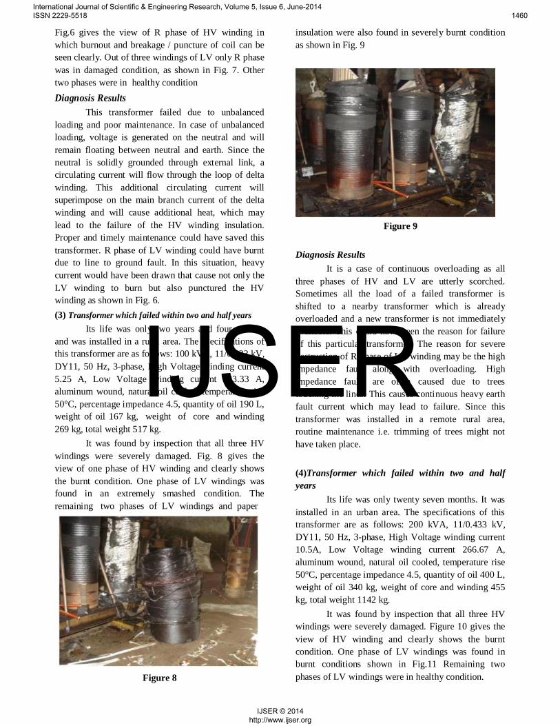
Fig.6 gives the view of R phase of HV winding inwhich burnout and breakage / puncture of coil can beseen clearly. Out of three windings of LV only R phasewas in damaged condition, as shown in Fig. 7. Othertwo phases were in healthy conditionDiagnosis Results
This transformer failed due to unbalancedloading and poor maintenance. In case of unbalancedloading, voltage is generated on the neutral and willremain floating between neutral and earth. Since theneutral is solidly grounded through external link, acirculating current will flow through the loop of deltawinding. This additional circulating current willsuperimpose on the main branch current of the deltawinding and will cause additional heat, which maylead to the failure of the HV winding insulation.Proper and timely maintenance could have saved thistransformer. R phase of LV winding could have burntdue to line to ground fault. In this situation, heavycurrent would have been drawn that cause not only theLV winding to burn but also punctured the HVwinding as shown in Fig. 6.(3) Transformer which failed within two and half years
Its life was only two years and four monthsand was installed in a rural area. The specifications ofthis transformer are as follows: 100 kVA, 11/0.433 kV,DY11, 50 Hz, 3-phase, High Voltage winding current5.25 A, Low Voltage winding current 133.33 A,aluminum wound, natural oil cooled, temperature rise50°C, percentage impedance 4.5, quantity of oil 190 L,weight of oil 167 kg, weight of core and winding269 kg, total weight 517 kg.
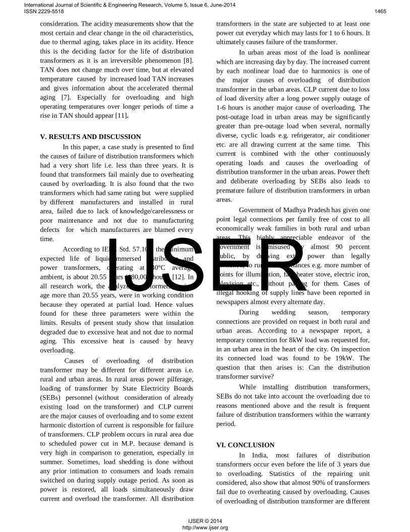
It was found by inspection that all three HVwindings were severely damaged. Fig. 8 gives theview of one phase of HV winding and clearly showsthe burnt condition. One phase of LV windings wasfound in an extremely smashed condition. Theremaining two phases of LV windings and paper
Figure 8
insulation were also found in severely burnt conditionas shown in Fig. 9
Figure 9
Diagnosis ResultsIt is a case of continuous overloading as all
three phases of HV and LV are utterly scorched.Sometimes all the load of a failed transformer isshifted to a nearby transformer which is alreadyoverloaded and a new transformer is not immediatelyavailable. This could have been the reason for failureof this particular transformer. The reason for severedestruction of R phase of LV winding may be the highimpedance fault along with overloading. Highimpedance faults are often caused due to treestouching the lines. This causes continuous heavy earthfault current which may lead to failure. Since thistransformer was installed in a remote rural area,routine maintenance i.e. trimming of trees might nothave taken place.
(4)Transformer which failed within two and halfyears
Its life was only twenty seven months. It wasinstalled in an urban area. The specifications of thistransformer are as follows: 200 kVA, 11/0.433 kV,DY11, 50 Hz, 3-phase, High Voltage winding current10.5A, Low Voltage winding current 266.67 A,aluminum wound, natural oil cooled, temperature rise50°C, percentage impedance 4.5, quantity of oil 400 L,weight of oil 340 kg, weight of core and winding 455kg, total weight 1142 kg.
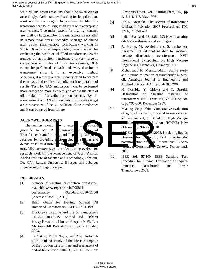
It was found by inspection that all three HVwindings were severely damaged. Figure 10 gives theview of HV winding and clearly shows the burntcondition. One phase of LV windings was found inburnt conditions shown in Fig.11 Remaining twophases of LV windings were in healthy condition.
International Journal of Scientific & Engineering Research, Volume 5, Issue 6, June-2014 ISSN 2229-5518 1460
IJSER © 2014 http://www.ijser.org
IJSER

Figure 10
Figure 11
Diagnosis ResultsOverloading/unbalanced loading is the major
cause of failure of this transformer. Thisoverloading/unbalanced loading may be due to newconnections to consumers above the capacity of thetransformer or due to power theft. Often a number ofnew connections are added to the existing transformerwithout calculating the load which it can supply andline operators connect these new loads to the mostreachable conductor i.e. B phase. Unequal loading inthree phase causes over loading in one phase.
Use of modern electronic devices i.e.nonlinear loads, in offices, industries as well asresidences is now increasing day by day due to its lowcost and high efficiency. The harmonic distortion ofcurrent is increasing with the enhanced use ofelectronic devices such as desktop computers, laptops,uninterrupted power supplies, television, mobile phonechargers, compact fluorescent tube etc. Thesenonlinear loads are mostly used in urban areas. Theseloads draw current in the form of short pulses insteadof sinusoidal wave. They draw more current than thefundamental current and cause overloading of thedistribution transformer. Therefore harmonic currentsproduced due to nonlinear loads may also be one of thecauses of its failure.
Theft of power by hooking the power line hasbeen a regular phenomenon in both rural and urbanareas. It can be assumed that power theft by some ofthe consumers might have been done by hooking theapproachable bottom most conductor i.e. B phase ofthe system. This resulted into severe overloading andburning of B Phase of LV winding as shown inFig.11.The B phase of HV winding was alsooverstressed by this overloading and got damaged asshown in Fig 10. Oil samples are taken from eachtransformer for DGA and all results are reported inTable I.TABLE I RESULTS OF DISSOLVED GAS ANALYSIS
ComponentAmount in ppm
Case (1) Case (2) Case (3) Case (4)
Hydrogen H2 63.281 46.451 57.464 43.92
Methane CH4 332.76 150.608 312.767 114.76
Ethane C2H6 170.29 51.795 132.756 76.178
Ethylene C2H4 1749.487 829.082 2716.73 674.137
Acetylene C2H2 0.102 0.0037 0.0297 0.0215
Carbon dioooxide CO2 2410.63 156.56 3539.12 546.44
Carbon mono-oxide CO 121.535 23.451 179.348 71.364
Results of DGA also agree with thesediagnosis results as ethylene is the principal gas withsome amount of ethane and methane in each case, thecause of which is overheating of the oil. Presence ofcarbon dioxide and carbon mono oxide indicate thepaper degradation.
IV. MEASUREMENT AND ANALYSIS OF OILPARAMETERS
Oil samples from 27 distribution transformers,which failed within the warranty period, are analysed.The voltage rating of all transformers is 11/0.4kV andthe capacity ratings are 25kVA, 63kVA, 100kVA and200kVA respectively. All transformers were installedin the state of Madhya Pradesh and supplied bydifferent manufacturers. Experimental analysis wasperformed on the oil samples taken from thesedistribution transformers. There is no singlemeasurement which can give a complete picture of thecondition of transformer oil. There are variousparameters which can be measured to assess thecondition of the oil such as density, flash point,relative permittivity, breakdown voltage, dissipationfactor, viscosity, specific resistance, total acid number
International Journal of Scientific & Engineering Research, Volume 5, Issue 6, June-2014 ISSN 2229-5518 1461
IJSER © 2014 http://www.ijser.org
IJSER

etc. Out of these parameters dielectric strength,viscosity and total acid number of the oil weremeasured and analyzed. According to manufacturers inIndia, same oil is used in power as well as distributiontransformers; therefore properties of oil from both thetransformers are presumed to be same. The normalvalues of BDV, viscosity and TAN according to Indianstandards 335 [6] are given in Table II.
TABLE II INDIAN STANDARD NORMAL VALUES
BDV Viscocity TAN
Above 60 kV(rms)
27cSt max at27°C and 12 cStat 40°C (IEC)
0.03 mgKOH/gmax
A. Breakdown VoltageMuller et al 2011 shows analysis of 37 oil
samples of distribution transformers with differentload histories and ages. These transformers were 10 to55 years old and were working satisfactorily. It wasfound that BDV of 31 samples was above 60kV and 18samples had BDV above 70kV as shown in Fig. 12.They were generally in a good conditionregardless of their age. Mohammad R 2008 givesmeasurement of some parameters for nine oil samplesof operating power transformers manufactured by thesame company. Fig. 13 shows that all nine oil samplesof operating power transformers had BDV in the rangeof 50 to 70kV.The aging of insulating paper and oil isstudied by Shim 2010 by performing acceleratedthermal aging test. Sealed aging test vessels containingcopper, laminated core, Kraft paper and insulating oilwere aged at 140°C for 500, 1000 and 1500 hoursrespectively. It has been reported that at operatingtemperature of 140°C, BDV was reduced from 55kVto 40kV i.e. BDV was reduced by about 30% of initialvalue, for aging time of 1500 hours (62.5 days only),which can be seen in Fig. 14. The test vessel doesnot represent the actual transformer and Fig. 14 onlyindicates the trend of variation. This trend is inagreement with present study of failed transformers inwhich BDV of all the 27 oil samples lies in the rangeof 12 to 46 kV, as shown in Fig. 15. This indicates thatthe temperature of the oil must have reached to above140°C. Hence it may be a deciding factor fordegradation of the oil due to thermal aging.
Figure 12 Transformer oil breakdown voltages in kV for each transformer oil sample [7].
Figure 13 Breakdown voltage of the oil specimens from transformers of different ages [8]
Figure 14 Breakdown voltage of two different typesof oil used for insulation [10]
International Journal of Scientific & Engineering Research, Volume 5, Issue 6, June-2014 ISSN 2229-5518 1462
IJSER © 2014 http://www.ijser.org
IJSER

Figure 15 BDV of the oil specimens ofpresent study
B. ViscosityMohammad R 2008 has reported that viscosity
of all 9 samples was between 10 to 14 cSt i.e. wellwithin the range as per IEC specifications, as shown inFig.16 These transformers were of the age 2 to 35years approximately and were working properly. Theviscosity of transformer oil is varying from 28.09 to65.0 cSt in the present study of 27 samples as shown inFig.17. This high value of viscosity will result ininefficient cooling of transformer and the temperatureof oil may exceed permissible limit. Hence it is adeciding factor for thermal aging of the oil.
Figure 16 Viscosity of the oil specimens fromfrom transformers having different ages [8]
Figure 17 Viscosity of the oil specimens of present studyC. Total Acid Number
TAN is defined as the acidity of the oil whichis milligrams of 0.1 normal KOH needed forneutralizing the acidity of 1 g oil. Reference [8] givesmeasurement of acidity of oil specimens taken from 43working transformers of different ages (up to 29 yearsold). It has been reported that 20 working transformershaving age up to 13 years had TAN less than 0.1 mgKOH/g oil and 18 transformers having age 14 to 25years had TAN from 0.1 to 0.18 mg KOH/g oil i.e. 38out of 43 transformers, having age of 1 to 25 years,had total acid number in the range of 0.06 to0.18 mg KOH/g oil which is evident from Fig. 18. Thismeans that up to the age of 25 years TAN remainedbelow 0.18 mg KOH/g because transformers were notoverloaded and hence not overheated.
Yoshida et al 1987 gives results ofinvestigation of changes in characteristics of celluloseinsulating materials i.e. insulating paper andpressboard, through accelerated tests using modelsof oil- impregnated insulating systems but thesemodel coils do not represent the actual transformer.Fig. 19 shows the increase in acid value of insulatingoil due to thermal aging in the presence of insulatingpaper only. It has been reported that aging of modelcoil for 12 months at a temperature of 140°C causedthe TAN to increase from 0.002 to 0.042mg KOH/gapproximately.
International Journal of Scientific & Engineering Research, Volume 5, Issue 6, June-2014 ISSN 2229-5518 1463
IJSER © 2014 http://www.ijser.org
IJSER

Figure 18 Acidity of the oil specimens taken from43 power transformers of various ages [8]
Figure 19 Increase in acid value of insulating oildue to thermal aging (Insulating paper) [9]
Figure 20 Increase in acid value of insulating oildue to thermal aging (Pressboard) [9].
Fig. 20 shows the increase in acid value ofinsulating oil due to thermal aging of model coil in thepresence of pressboard only. It can be seen that atemperature of 140°C and 6 months aging caused theTAN to increase from 0.002 to 0.105 mg KOH/gapproximately.
Figure 21 Total Acid Number [10]
Figure 22 Total Acid Number of the oilspecimens of present study
Shim 2010 simulated the distributiontransformer by sealed vessels containing all materialsin the same ratio as in transformer and reportedthat TAN for mineral oil increases from 0.01 to0.26mg KOH/g oil at a temperature of 140°C for agingtime of 1500 hours as shown in Fig. 21. This validatesthe results of the present study. In presentinvestigations, it has been found that TAN of all oilsamples varies from 0.224 to 1.12 mg KOH/g asshown in Fig. 22. TAN of the 21 oil samples liesbetween 0.224 and 0.336. This increase in TAN is dueto combined thermal aging of insulating paper,pressboard and oil in actual distribution transformers.
The experiments, conducted on vessels, byYoshida et al 1987 & Shim 2010 do not represent anactual transformer because actual windings, hot spots,core, poor workmanship etc. are not taken into
International Journal of Scientific & Engineering Research, Volume 5, Issue 6, June-2014 ISSN 2229-5518 1464
IJSER © 2014 http://www.ijser.org
IJSER
consideration. The acidity measurements show that themost certain and clear change in the oil characteristics,due to thermal aging, takes place in its acidity. Hencethis is the deciding factor for the life of distributiontransformers as it is an irreversible phenomenon [8].TAN does not change much over time, but at elevatedtemperature caused by increased load TAN increasesand gives information about the accelerated thermalaging [7]. Especially for overloading and highoperating temperatures over longer periods of time arise in TAN should appear [11].
V. RESULTS AND DISCUSSIONIn this paper, a case study is presented to find
the causes of failure of distribution transformers whichhad a very short life i.e. less than three years. It isfound that transformers fail mainly due to overheatingcaused by overloading. It is also found that the twotransformers which had same rating but were suppliedby different manufacturers and installed in ruralarea, failed due to lack of knowledge/carelessness orpoor maintenance and not due to manufacturingdefects for which manufacturers are blamed everytime.
According to IEEE Std. 57.100, the minimumexpected life of liquid-immersed distribution andpower transformers, operating at 30°C averageambient, is about 20.55 years (180,000 hours) [12]. Inall research work, the analyzed transformers havingage more than 20.55 years, were in working conditionbecause they operated at partial load. Hence valuesfound for these three parameters were within thelimits. Results of present study show that insulationdegraded due to excessive heat and not due to normalaging. This excessive heat is caused by heavyoverloading.
Causes of overloading of distributiontransformer may be different for different areas i.e.rural and urban areas. In rural areas power pilferage,loading of transformer by State Electricity Boards(SEBs) personnel (without consideration of alreadyexisting load on the transformer) and CLP currentare the major causes of overloading and to some extentharmonic distortion of current is responsible for failureof transformers. CLP problem occurs in rural area dueto scheduled power cut in M.P. because demand isvery high in comparison to generation, especially insummer. Sometimes, load shedding is done withoutany prior intimation to consumers and loads remainswitched on during supply outage period. As soon aspower is restored, all loads simultaneously drawcurrent and overload the transformer. All distribution
transformers in the state are subjected to at least onepower cut everyday which may lasts for 1 to 6 hours. Itultimately causes failure of the transformer.
In urban areas most of the load is nonlinearwhich are increasing day by day. The increased currentby each nonlinear load due to harmonics is one ofthe major causes of overloading of distributiontransformer in the urban areas. CLP current due to lossof load diversity after a long power supply outage of1-6 hours is another major cause of overloading. Thepost-outage load in urban areas may be significantlygreater than pre-outage load when several, normallydiverse, cyclic loads e.g. refrigerator, air conditioneretc. are all drawing current at the same time. Thiscurrent is combined with the other continuouslyoperating loads and causes the overloading ofdistribution transformer in the urban areas. Power theftand deliberate overloading by SEBs also leads topremature failure of distribution transformers in urbanareas.
Government of Madhya Pradesh has given onepoint legal connections per family free of cost to alleconomically weak families in both rural and urbanareas. This highly appreciable endeavor of thegovernment is misused by almost 90 percentpublic, by drawing extra power than legallypermitted, to run their appliances e.g. more number ofpoints for illumination, fan, heater stove, electric iron,television etc., without paying for them. Cases ofillegal hooking of supply lines have been reported innewspapers almost every alternate day.
During wedding season, temporaryconnections are provided on request in both rural andurban areas. According to a newspaper report, atemporary connection for 8kW load was requested for,in an urban area in the heart of the city. On inspectionits connected load was found to be 19kW. Thequestion that then arises is: Can the distributiontransformer survive?
While installing distribution transformers,SEBs do not take into account the overloading due toreasons mentioned above and the result is frequentfailure of distribution transformers within the warrantyperiod.
VI. CONCLUSIONIn India, most failures of distribution
transformers occur even before the life of 3 years dueto overloading. Statistics of the repairing unitconsidered, also show that almost 90% of transformersfail due to overheating caused by overloading. Causesof overloading of distribution transformer are different
International Journal of Scientific & Engineering Research, Volume 5, Issue 6, June-2014 ISSN 2229-5518 1465
IJSER © 2014 http://www.ijser.org
IJSER
for rural and urban areas and should be taken care ofaccordingly. Deliberate overloading for long durationsmust not be encouraged. In practice, the life of atransformer can be as long as 30 years with appropriatemaintenance. Two main reasons for low maintenanceare: firstly, a large number of transformers are installedin remote rural areas. Secondly, shortage of skilledman power (maintenance technicians) working inSEBs. DGA is a technique widely recommended forevaluating the health of oil filled transformers. As thenumber of distribution transformers is very large incomparison to number of power transformers, DGAcannot be performed on each and every distributiontransformer since it is an expensive method.Moreover, it requires a large quantity of oil to performthe analysis and requires expertise for interpretation ofresults. Tests for TAN and viscosity can be performedmore easily and more frequently to assess the state ofoil insulation of distribution transformers. By themeasurement of TAN and viscosity it is possible to geta clear overview of the oil condition of the transformerand it can be saved from failure.
ACKNOWLEDGEMENTSThe authors would like to express their sincere
gratitude to Mr. R. Chansoriya, Proprietor ofTransformer Manufacturing and Repairing Company,Jabalpur for providing photographs, oil samples anddetails of failed distribution transformers. The authorsgratefully acknowledge the facilities provided forresearch work by the Management of Guru RamdasKhalsa Institute of Science and Technology, Jabalpur,Dr. C.V. Raman University, Bilaspur and JabalpurEngineering College, Jabalpur.
REFERENCES[1] Number of existing distribution transformer
available-www.mperc.nic.in/290811performance -Standards-2010-11.pdf[Accessed:Dec.23, 2011]
[2] IEEE Guide for loading Mineral OilImmersed Transformers, IEEE C57.91-1995
[3] D.P.Gupta, Loading and life of transformersTRANSFORMERS, Second Ed., BharatHeavy Electricals Limited Bhopal (M P), TataMcGraw-Hill Publishing Company Limited,2003.
[4] S. Yakov, M. de Nigris, and P.G. AntonioliCESI, Milano, Study of the life consumptionof Distribution transformers and assessment ofend-of-life criteria CIRED, 12th Int.Conf. on:
Electricity Distri., vol.1, Birmingham, UK, pp1.16/1-1.16/5, May 1993.
[5] Jon L. Giesecke, The secrets of transformercooling, InfraMation 2007 Proceedings, ITC121A, 2007-05-24
[6] Indian Standards IS: 335-1993 New Insulatingoils for transformers and switchgear.
[7] A. Muller, M. Jovalekic and S. Tenbohlen,Asessment of oil analysis data for mediumvoltage distribution transformers, XVIIInternational Symposium on High VoltageEngineering, Hannover, Germany, 2011
[8 Mohammad R. Meshkatoddini, Aging studyand lifetime estimation of transformer mineraloil, American Journal of Engineering andApplied Sciences 1(4); pp 384-388, 2008
[9] H. Yoshida, Y. Ishioka and T. Suzuki,Degradation of insulating materials oftransformers, IEEE Trans. E I, Vol. E1-22, No.6, pp 795-800, December 1987.
[10] Myeong- Seop. Shim, Comparative evaluationof aging of insulating material in natural esterand mineral oil, Int. Conf. on High VoltageEngineering and Applications (ICHVE), NewOrleans, pp 393-396, 2010.
[11] IEC Standard 62021-1:2003, Insulating liquidsDetermination of acidity Part 1: Automaticpotentiometric titration, International Electrotechnical Commission, Geneva, Switzerland,2003.
[12] IEEE Std. 57.100, IEEE Standard TestProcedure for Thermal Evaluation of Liquid-Immersed Distribution and PowerTransformers 2001.
International Journal of Scientific & Engineering Research, Volume 5, Issue 6, June-2014 ISSN 2229-5518 1466
IJSER © 2014 http://www.ijser.org
IJSER