Embed Size (px)
Citation preview

Assembly of 6 x 6 Double Door Apex Shed ©
We recommend that the base onto which your building will stand should be at least 75mm larger in each direction than the total floor size of the building. Actual floor area of the building: 1790 x 1790mmTotal height clearance: 2280mmThe chosen position in your garden for the siting of the building should be excavated toa depth of 75mm to allow a base of sand, on to which paving slabs can be evenly laid - THEY MUST BE LEVEL AND FIRM.
PLEASE LAY OUT PARTS AND CHECK OFF AGAINST CHECK LIST BELOW:QTY DESCRIPTION
14 Timber sections A x2, B x2, C x1, D x2, E x1, Fx2, G x2
1 Window frame C12 Doors D1, D21 Large door stop strip M3 Small door stop strips L2 OSB roof sections H4 Roof bearers H11 Piece felt 1m wide x 4m long Q1 Piece felt 0.5m x 2m long Q7 Cover strips K4 Fascia boards I2 Diamonds J1 Pane glazing material V4 Pieces glazing beading W
QTY DESCRIPTION2 Metal plates A11 Padbolt + housing I + I22 Small bolts I36 Door hinges D32 Window hinges C21 Casement stay C32 Casement stay pins C4
77 25mm screws30 60mm screws
101 40mm nails8 10mm screws3 60mm nails
96 Felt nails8 15mm panel
Tools RequiredPosidrive screwdriver (electric is best)Drill, 6mm drill bit, 8mm drill bitHammerSandpaper (to smooth any rough edges)Cutting knifeTape measureStep ladderRulerPencilSaw
IMPORTANT!PLEASE READ PRIOR TO ASSEMBLY OFTHE BUILDINGEVERY PRECAUTION IS TAKEN TOENSURE THAT YOUR BUILDING HAS NOELEMENT INCORRECTLY PLACED ORPOSSIBLY HAZARDOUS, HOWEVERPRIOR TO USE PLEASE CHECK ALLSURFACES FOR THE FOLLOWING:1 RAISED GRAIN, SPLINTERS: sand
down timber to smooth finish2 NAIL/SCREW/PIN HEADS PROUD: tap
home to be flush with surface of timber3 DAMAGED SCREW HEADS
RESULTING IN SHARP SPLINTERS OFMETAL: replace
4 SHARP ENDS OF NAILS/ SCREWS/PINS PROTRUDING THROUGH THEPANEL: remove and reposition.
5 ENSURE ALL PARTS ARE SECUREDAGAINST REASONABLE FORCE:remove and refit
6 ENSURE THERE ARE NO LOOSEPARTS: remove and refit/discardWe recommend that protective
gloves be worn throughout
Wood is a natural product and is thereforeprone to changes in appearance, includingsome warping, movement and splitting,particularly during unusual climatic conditions(long hot or wet spells of weather). As a naturaloccurrence this is not covered by a guarantee.
PLEASE NOTE
Completed 6 x 6 Double Door Apex Apex Shed
Q
JJ
I I
D3
D3
D3
M
K
H
H1
D2
D1
H
A1
D
D
L
WV
E
F
K
K
K
G
FB B
A
A
H1
C1 CKG
11/0
8
Treat with a suitable decorative wood finish immediately. We recommend that all timber pieces be treated again prior to assembly and again within 3 months of assembly. We further recommend that all pieces are treated again at least annually or as frequently as the instructions on the product used recommends.We would suggest that all wall panels be treated in an upside-down position to allow the finish/treatment to ingress into the tongue and groove jointing.We would also remind you that you would rarely (if ever) be able to re-treat the underside of the floor following assembly. We strongly recommend that the underside of the floor is treated an absolute minimum of twice (not including pre-treatment).Garden buildings are not waterproof, therefore on assembling building recommend using a silicon based sealant between wall panels and between wall panels and floor.
Parts List
I2
I1 I3
G3
C2C4
C3
A1
Hardware Bag Contents
Treatment/Care of your Garden Building
Preparation of Base
Thank you and congratulations on the purchase of your Shire Garden Building. We believe that this product will give you many years of excellent service. This is a natural product manufactured to a high standard therefore if you have any queries or experience any difficulties then please contact our customer service hotline 01945 46 89 10 or01945 46 89 11 or 01945 46 89 12. Normal office hours: 8.30 am to 5.00 pm Monday toFriday. Answer phone all other times.
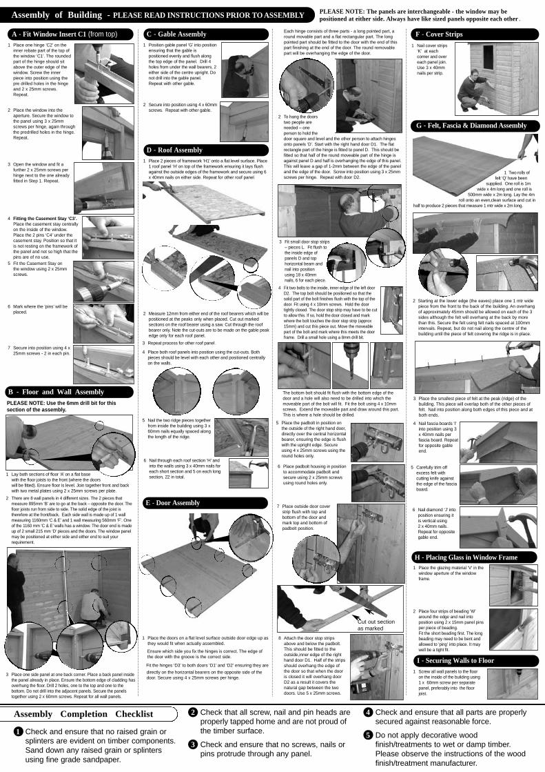
1 Check and ensure that no raised grain or splinters are evident on timber components. Sand down any raised grain or splinters using fine grade sandpaper.
2 Check that all screw, nail and pin heads are properly tapped home and are not proud ofthe timber surface.
3 Check and ensure that no screws, nails or pins protrude through any panel.
4 Check and ensure that all parts are properly secured against reasonable force.
5 Do not apply decorative wood finish/treatments to wet or damp timber.Please observe the instructions of the wood finish/treatment manufacturer.
Assembly Completion Checklist
Assembly of Building - PLEASE READ INSTRUCTIONS PRIOR TO ASSEMBLY PLEASE NOTE: The panels are interchangeable - the window may bepositioned at either side. Always have like sized panels opposite each other .
A - Fit Window Insert C1 (from top)1 Place one hinge ‘C2’ on the
inner rebate part of the top ofthe window ‘C1’. The roundedpart of the hinge should sitabove the outer edge of thewindow. Screw the innerpiece into position using thepre drilled holes in the hingeand 2 x 25mm screws.Repeat.
2 Place the window into theaperture. Secure the window tothe panel using 3 x 25mmscrews per hinge, again throughthe predrilled holes in the hinge.Repeat.
3 Open the window and fit afurther 2 x 25mm screws perhinge next to the one alreadyfitted in Step 1. Repeat.
5 Fit the Casement Stay onthe window using 2 x 25mmscrews.
6 Mark where the ‘pins’ will beplaced.
7 Secure into position using 4 x25mm screws - 2 in each pin.
4 Fitting the Casement Stay ‘C3’.Place the casement stay centrallyon the inside of the window.Place the 2 pins ‘C4’ under thecasement stay. Position so that itis not resting on the framework ofthe panel and not so high that thepins are of no use.
B - Floor and Wall Assembly
1 Lay both sections of floor ‘A’ on a flat basewith the floor joists to the front (where the doorswill be fitted). Ensure floor is level. Join together front and backwith two metal plates using 2 x 25mm screws per plate.
PLEASE NOTE: Use the 6mm drill bit for thissection of the assembly.
1 Position gable panel ‘G’ into positionensuring that the gable ispositioned evenly and flush alongthe top edge of the panel. Drill 4holes from under the wall bearers, 2either side of the centre upright. Donot drill into the gable panel.Repeat with other gable.
2 Secure into position using 4 x 60mmscrews. Repeat with other gable.
C - Gable Assembly
1 Place 2 pieces of framework ‘H1’ onto a flat level surface. Place1 roof panel ‘H’ on top of the framework ensuring it lays flushagainst the outside edges of the framework and secure using 6x 40mm nails on either side. Repeat for other roof panel.
D - Roof Assembly
3 Repeat process for other roof panel .
5 Nail the two ridge pieces togetherfrom inside the building using 3 x60mm nails equally spaced alongthe length of the ridge.
6 Nail through each roof section ‘H’ andinto the walls using 3 x 40mm nails foreach short section and 5 on each longsection, 22 in total.
2 Measure 12mm from either end of the roof bearers which will bepositioned at the peaks only when placed. Cut out markedsections on the roof bearer using a saw. Cut through the roofbearer only. Note the cut-outs are to be made on the gable peakedge only for each roof panel.
4 Place both roof panels into position using the cut-outs. Bothpieces should be level with each other and positioned centrallyon the walls.
E - Door Assembly
1 Place the doors on a flat level surface outside door edge up asthey would fit when actually assembled.
Ensure which side you fix the hinges is correct. The edge of the door with the groove is the correct side.
Fit the hinges ‘D3’ to both doors ‘D1’ and ‘D2’ ensuring they aredirectly on the horizontal bearers on the opposite side of the door. Secure using 4 x 25mm screws per hinge.
Each hinge consists of three parts - a long pointed part, around movable part and a flat rectangular part. The longpointed part should be fitted to the door with the end of thispart finishing at the end of the door. The round removablepart will be overhanging the edge of the door.
2 To hang the doorstwo people areneeded – oneperson to hold thedoor square and level and the other person to attach hingesonto panels ‘D’. Start with the right hand door D1. The flatrectangle part of the hinge is fitted to panel D. This should befitted so that half of the round moveable part of the hinge isagainst panel D and half is overhanging the edge of this panel.This will leave a gap of 1-2mm between the edge of the paneland the edge of the door. Screw into position using 3 x 25mmscrews per hinge. Repeat with door D2.
3 Fit small door stop strips– pieces L. Fit flush tothe inside edge ofpanels D and tophorizontal beam andnail into positionusing 18 x 40mmnails, 6 for each piece.
The bottom bolt should fit flush with the bottom edge of thedoor and a hole will also need to be drilled into which themoveable part of the bolt will fit. Fit the bolt using 4 x 10mmscrews. Extend the moveable part and draw around this part.This is where a hole should be drilled.
5 Place the padbolt in position onthe outside of the right hand door,directly over the central horizontalbearer, ensuring the edge is flushwith the upright edge. Secureusing 4 x 25mm screws using theround holes only.
6 Place padbolt housing in positionto accommodate padbolt andsecure using 2 x 25mm screwsusing round holes only.
4 Fit two bolts to the inside, inner edge of the left doorD2. The top bolt should be positioned so that thesolid part of the bolt finishes flush with the top of thedoor. Fit using 4 x 10mm screws. Hold the doortightly closed. The door stop strip may have to be cutto allow this. If so, hold the door closed and markwhere the bolt touches the door stop strip (approx15mm) and cut this piece out. Move the moveablepart of the bolt and mark where this meets the doorframe. Drill a small hole using a 8mm drill bit.
8 Attach the door stop stripsabove and below the padbolt.This should be fitted to theoutside,inner edge of the righthand door D1. Half of the stripsshould overhang the edge ofthe door so that when the dooris closed it will overhang doorD2 as a result it covers thenatural gap between the twodoors. Use 5 x 25mm screws.
Cut out section as marked
7 Place outside door coverstrip flush with top andbottom of the door andmark top and bottom ofpadbolt position.
1 Nail cover strips‘K’ at eachcorner and overeach panel join.Use 3 x 40mmnails per strip.
F - Cover Strips
G - Felt, Fascia & Diamond Assembly
1 Two rolls offelt ‘Q’ have been
supplied. One roll is 1mwide x 4m long and one roll is
500mm wide x 2m long. Lay the 4mroll onto an even,clean surface and cut in
half to produce 2 pieces that measure 1 mtr wide x 2m long.
3 Place the smallest piece of felt at the peak (ridge) of thebuilding. This piece will overlap both of the other pieces offelt. Nail into position along both edges of this piece and atboth ends.
1 Place the glazing material ‘V’ in thewindow aperture of the windowframe.
2 Place four strips of beading ‘W’around the edge and nail intoposition using 2 x 15mm panel pinsper piece of beading.Fit the short beading first. The longbeading may need to be bent andallowed to ‘ping’ into place. It maywell be a tight fit.
1 Screw all wall panels to the flooron the inside of the building using1 x 60mm screw per separatepanel, preferably into the floorjoist.
H - Placing Glass in Window Frame
I - Securing Walls to Floor
5 Carefully trim offexcess felt withcutting knife againstthe edge of the fasciaboard.
6 Nail diamond ‘J’ intoposition ensuring itis vertical using2 x 40mm nails.Repeat for oppositegable end.
4 Nail fascia boards ‘I’into position using 3x 40mm nails perfascia board. Repeatfor opposite gableend.
2 Starting at the lower edge (the eaves) place one 1 mtr widepiece from the front to the back of the building. An overhangof approximately 45mm should be allowed on each of the 3sides although the felt will overhang at the back by morethan this. Secure the felt using felt nails spaced at 100mmintervals. Repeat, but do not nail along the centre of thebuilding until the piece of felt covering the ridge is in place.
2 There are 8 wall panels in 4 different sizes. The 2 pieces thatmeasure 895mm ‘B’ are to go at the back – opposite the door. Thefloor joists run from side to side. The solid edge of the joist istherefore at the front/back. Each side wall is made up of 1 wallmeasuring 1160mm ‘C & E’ and 1 wall measuring 560mm ‘F’. Oneof the 1160 mm ‘C & E’ walls has a window. The door end is madeup of 2 small 215 mm ‘D’ pieces and the doors. The window panelmay be positioned at either side and either end to suit yourrequirement.
3 Place one side panel at one back corner. Place a back panel insidethe panel already in place. Ensure the bottom edge of cladding hasoverhung the floor. Drill 2 holes, one to the top and one to thebottom. Do not drill into the adjacent panels. Secure the panelstogether using 2 x 60mm screws. Repeat for all wall panels.