Embed Size (px)
DESCRIPTION
s m
Citation preview
HEAT EXCHANGER

Tube-side Multipass arrangements
A. Two Pass
2
1
Pass rib

B. Four Pass
4
1
3
2
1
4
1
3 2
4
1
3
2
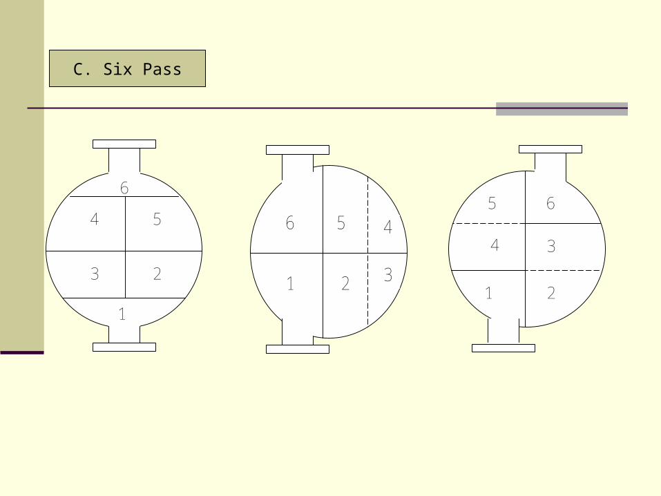
C. Six Pass
6
1
4 5
3 2
6
1
5
2
4
3
6
1
5
4 3
2

D. Eight Pass
8
1
5 6
4 3
7
2
8
1
5
6
4
3
7
2
8
1
5 6
4 3
7
2
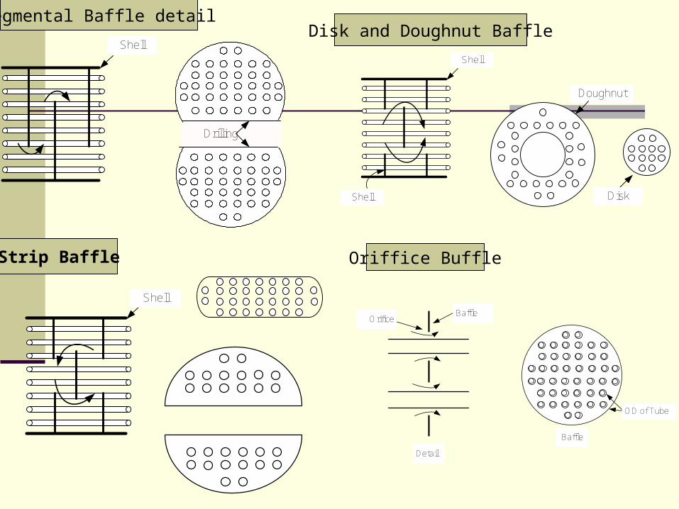
Shell
Segmental Baffle detail
Shell
Strip Baffle
Disk and Doughnut Baffle
Shell
Shell
Doughnut
Disk
Oriffice Buffle
OrificeBaffle
Detail
OD of Tube
Baffle
Drilling

Rod from baffle #1
Rod from baffle #3
Rod from baffle #2
Rod from baffle #4
Rod from baffle #3
Rod Baffles untuk meminimalisasi Tube vibrations, dimana tube tersebut
didukung empat rods
Baffle #1
Rod Baffle #2
Rod Baffle #3
Rod Baffle #2
Skid Bar
Baffle ring

HOW TO SELECT THE OPTIMUM SHELL-AND-TUBE HEAT EXCHANGER

FLUID ALLOCATION
CORROSION Need fewer costly alloy components if the corrosive fluid is inside the tubes
FOULING Placing the fouling liquid in the tubes allows better velocity control;
Increased velocities tend to reduce fouling;
Straight tubes allow mechanical cleaning without removing the tube bundle
TEMPERATURE High temperature requires special or expensive alloy materials;
Fewer alloy components are needed when the hot fluid is placed within the tubes
PRESSURE Placing a high-pressure stream in the tubes will require fewer high-pressure components
PRESSURE DROP For the same pressure drop, higher heat-transfer coefficients are obtained on the tubeside;
A fluid with a low allowable pressure drop should generally be placed inside the tubes
VISCOSITY Higher heat-transfer rates are ordinarily obtained by placing a viscous fluid on the shell side
FLOWRATE The lower flowrate fluid on the shellside results in a more economical design. Turbulence exists on the shellside at much lower velocities than within the tubes.

CONSIDERATIONS BY THE DESIGNER
Evaluate the many variables in establishing the following characteristics of the heat exchanger:
1 Tube O.D. and length 8 Actual Pressure Drops
2 Tube Pitch 9 Shell Size
3 Number of Tube Passes 10 Fluid Distribution at the Inlet and Outlet of the Shell
4 Number of Shell Passes 11 Tube-to-tubesheet Attachement
5 Number of Baffles and Baffle Type 12 Ease of Maintenance
6 Number of Shells 13 Vibration, operating differential-expansion between shell and tubes, and other potential problem areas.
7 Fluid Velocities

TUBE SIZE AND LENGTH
* HE designs with small-diameter tubes (5/8-in to 1-in O.D.) are more economical than designs with larger tubes, because the smaller tubes provide for a more compact unit.* 5/8-in to 1-in O.D. tubes are the smallest considered for process HE, but there are some applications where smaller tubes may be better.
* HE designs with small-diameter tubes (5/8-in to 1-in O.D.) are more economical than designs with larger tubes, because the smaller tubes provide for a more compact unit.* 5/8-in to 1-in O.D. tubes are the smallest considered for process HE, but there are some applications where smaller tubes may be better.
Larger-diameter tubes are used when heavy fouling is expected, and when the inside of the tubes is to be cleaned mechanically.
Larger-diameter tubes are used when heavy fouling is expected, and when the inside of the tubes is to be cleaned mechanically.
Because tubes in the 5/8 – 1 –in-O.D. range are normally common for shell-and-tubeexchangers, tubes in these sizes are more readily available in various materials ofconstructions.
Because tubes in the 5/8 – 1 –in-O.D. range are normally common for shell-and-tubeexchangers, tubes in these sizes are more readily available in various materials ofconstructions.
The Investment per unit area of heat transfer surface is less for longer heat exchangers.Therefore, should avoid restrictions on length wherever possible.
The Investment per unit area of heat transfer surface is less for longer heat exchangers.Therefore, should avoid restrictions on length wherever possible.

TUBE PITCH OR ARRANGEMENT
Tubes are generally arranged on a triangular, square or rotated-square pitchTubes are generally arranged on a triangular, square or rotated-square pitch
Although the tube pitch can vary fir a given tube size, the designer should limitthe center-to-center spacing to the minimum, as outlined in the TEMA Standards, for good mechanical design
Although the tube pitch can vary fir a given tube size, the designer should limitthe center-to-center spacing to the minimum, as outlined in the TEMA Standards, for good mechanical design
Triangular-tube patterns provide better shellside heat-transfer coefficients in sensible-heatExchange, and provide more surface area for a given shell diameter
Triangular-tube patterns provide better shellside heat-transfer coefficients in sensible-heatExchange, and provide more surface area for a given shell diameter
Square-pitch tube patterns are generally used when mechanical cleaning of the outside of the tubes is expected; however, square-and rotated-square tube patterns provide lowerpressure drops and lower heat-transfer coefficients in most cases involving sensible heat
Square-pitch tube patterns are generally used when mechanical cleaning of the outside of the tubes is expected; however, square-and rotated-square tube patterns provide lowerpressure drops and lower heat-transfer coefficients in most cases involving sensible heat
Some spaced triangular pitches are required to facilitate lower pressure drops or reduceshellside velocities
Some spaced triangular pitches are required to facilitate lower pressure drops or reduceshellside velocities

SHELL BAFFLING
Baffles are used to direct the shellside fluid through a prescribed path, and to support the tubeswithin the bundle. Baffles are called tube supports, if this is their primary purpose. The threemost common baffle types:
SEGMENTAL BAFFLES
Provides a high degree of turbulance and good heat transfer because it directs the fluid over the tubes primarily in cross-flow;
Unless the shellside fluid is being condensed:
A horizontal baffle cut should be used to reduce accumulations of deposits at the bottom of the shell and to prevent stratification of the shellside fluid;
A vertical baffle cut is required for horizontal condensers to allow the condensate to flow freely without covering or flooding an excessive amount of tubes
Baffle cuts for segmental baffles are expressed as percentage values of the diameter or net free area. A 20%-diameter cut is considered optimum because it permits the highest heat transfer for a given pressure drop
For large HE with high flowrates, it is often more economical to omit tubes in the baffle-window area. This provides for better cross-flow, while providing support for all tubes at every baffle. The ‘no-tubes-in-the-window’ baffle design is often necessary to prevent flow-induced tube vibration.

SHELL BAFFLING (contunied …..)
MULTISEGMENTAL BAFFLES
Characterized by large open areas, this type can be used to reduce baffle spacing or to reduce cross-flow because of pressure-drop limitations
Certain types of baffles allow the fluid to flow nearly parallel to the tubes, offering a much lower pressure drop
LONGITUDINAL BAFFLES
Provides for multipass or split-flow, shellside-flow patterns
It can be welded to the shell, or sealed against it by a flex seal or other device
Sealing of the long baffle against the shell by means other than welding can be done when the pressure drop is relatively low on the shellside (less than 12 psi)

FOULING
Dikemukakan oleh Somerscales (1980)6 Kategori dari Thermal Fouling :1. Precipitation Fouling (substansi terlarut)2. Particulate Fouling ( padatan tersuspensi)3. Chemical Reaction Fouling (deposit karena
reaksi kimia)4. Corrosion Fouling ( transfer panas permukaan)5. Biological Fouling (organisme biologi )6. Freezing Fouling (pemadatan pada cairan)
Precipitation dan Freezing Fouling meliputi kristalisasi pada permukaan
Kategori 1 – 5 disebabkan oleh pemanasan cairan, menimbulkan efek saling menguatkan atau efek saling melemahkan
Kategori 6 disebabkan oleh pendinginan cairan

Cost of FoulingDikemukakan oleh Von Nostrand et al (1981)
dan Pritchard (1981)
Cost Total cost
Capital cost $ 100 million
Energy cost $ 60 million
Maintenance cost $ 80 million
Shutdown cost $ 60 million
Total cost $ 300 million

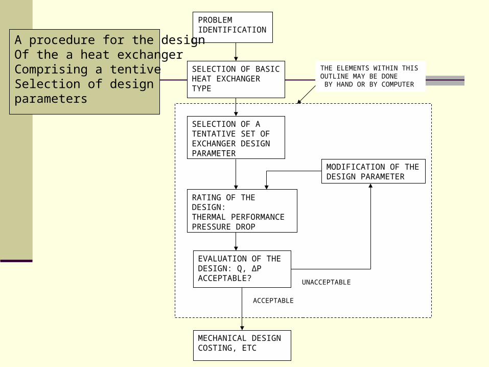
PROBLEMIDENTIFICATION
SELECTION OF BASICHEAT EXCHANGER TYPE
SELECTION OF A TENTATIVE SET OF EXCHANGER DESIGN PARAMETER
MODIFICATION OF THE DESIGN PARAMETER
RATING OF THE DESIGN:THERMAL PERFORMANCE PRESSURE DROP
EVALUATION OF THE DESIGN: Q, ∆P ACCEPTABLE?
MECHANICAL DESIGN COSTING, ETC
UNACCEPTABLE
ACCEPTABLE
THE ELEMENTS WITHIN THIS OUTLINE MAY BE DONE BY HAND OR BY COMPUTER
A procedure for the designOf the a heat exchangerComprising a tentive Selection of design parameters

FLOW RATES
FOULING FACTORS
FLUID PROPERTIES
EXCHANGER CONFIGURATION
PRESSURES
TEMPERATURES
RATING PROGRAM
1GEOMETRY CALCULATIONS
2HEAT TRANSFER CORELATIONS
3PRESSURE DROP CORELATIONS
PRESSURE DROPS
OUTLET TEMPERATURES(LENGTH FIXED)
LENGTH (DUTY FIXED)
Rating of performance

IS∆PT < ∆PT
*
AND∆PS < ∆PS
*
?
ADJUSTINTERNAL PARAMETERS
RE-RATE
ADD SHELLIN PARALLEL
RE-RATE
RE-RATE
RE-RATEADD SHELLIN PARALLEL
DECREASE SHELLDIAMETER
ADJUST INTERNALPARAMETERS TO STANDARD VALUES COUNTINUE
RATING PROGRAMINITIAL OUTPUT:LENGTH OF LARGESTDIAMETER SHELL, FEWESTTUBE PASSES, GREATESTBAFFLE SPACING
IS∆PS < ∆PS
*
AND∆PT < ∆PT
*
?
?
IS∆PS < ∆PS
*
OR∆PT < ∆PT
*
?
ISL < L*
?
NO
YES
NO
NO
NO
YES
YES
YES
Modification of design if necessary and re-rating to meet specification
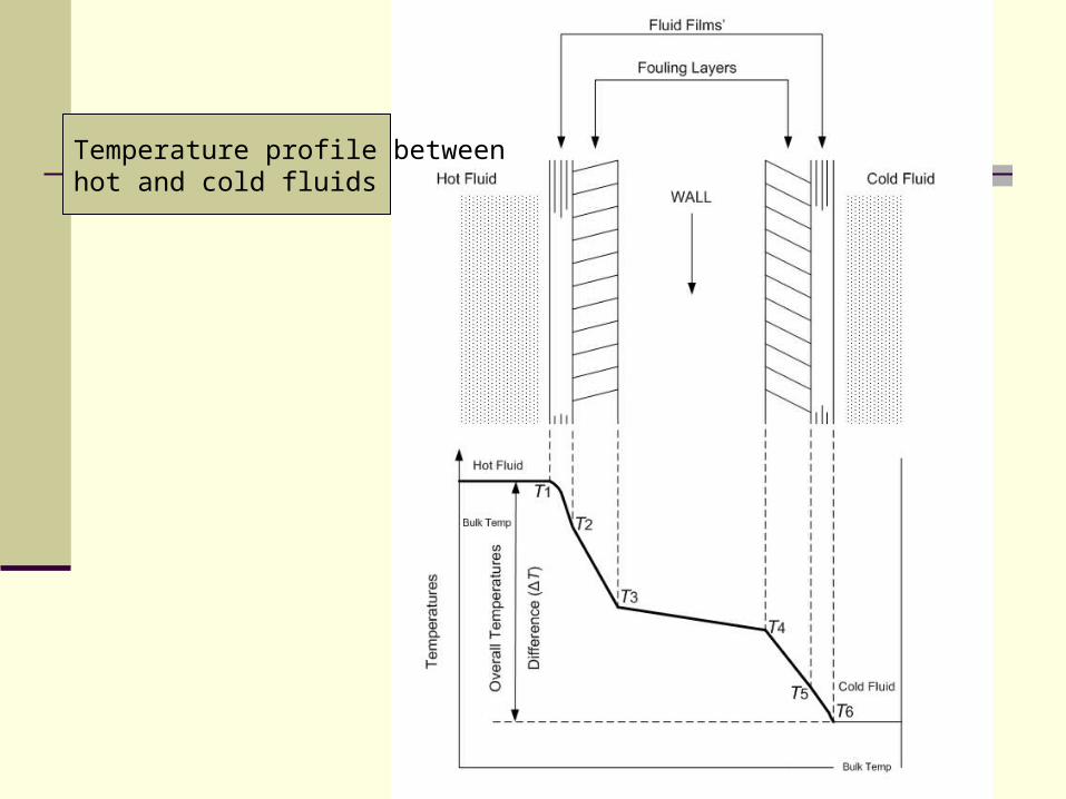
Temperature profile between hot and cold fluids

T1 – T2 = Q/αiAi ….(1.a)
T2 – T3 = Q/αfiAi ….(1.b)
T3 – T4 = Q/αwAw ….(1.c)
T4 – T5 = Q/αtoAo ….(1.d)
T5 – T6 = Q/αoAo ….(1.e)
Dimana : αi , αo = koefisien transfer panas film
αfi , αto = konduktansi fouling layer
αw = konduktansi dinding permukaan perpindahan panas
Ai , Ao = area permukaan perpindahan panas pada masing-masing
dinding
Aw = mean surface area dinding

oootowwitiii
oi AAAAAQTTT
11111
)(
)/(
1
)/(
1
)/(
1
)/(
1
)/(
1
refoorefotorefwwrefitirefiiref AAAAAAAAAA
QTA
Dengan menjumlahkan kelima persamaan sebelumnya, didapat :
Dikalikan dengan Aref pada masing-masing sisi, didapat :
Atau
refref U
QTA
)/(
1
)/(
1
)/(
1
)/(
1
)/(
11
refoorefotorefwwrefifirefiiref AAAAAAAAAAU
, 1/Uref = overall resistance

Untuk Cylindrical Tube :
oowioiioio rrAArAA
U /1///1
1
resistance walltube2
)/ln(
w
ioow
dddr

One Shell pass, two or more tube passes

One Shell pass, two or more tube passes

Two Shell passes, four or more Tube passes
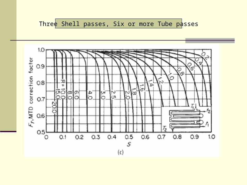
Three Shell passes, Six or more Tube passes

Four Shell passes, Eight or more Tube passes

Six Shell passes, Twelve or more Tube passes
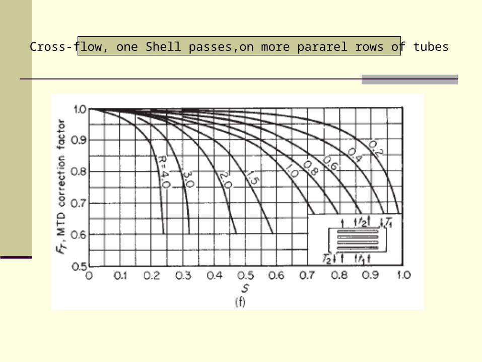
Cross-flow, one Shell passes,on more pararel rows of tubes

Cross-flow, two passes, two rows of tubes, for more than two passes use 0.1TF

Cross-flow, one Shell passes, one tube pass, both fluids unmixed
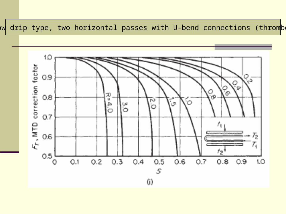
Cross-flow drip type, two horizontal passes with U-bend connections (thrombone type)

Cross-flow (drip type) helical coils with two turns
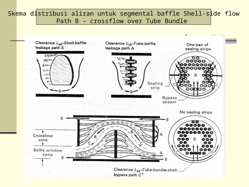
Skema distribusi aliran untuk segmental baffle Shell-side flowPath B – crossflow over Tube Bundle
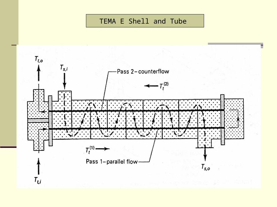
TEMA E Shell and Tube

Heat Exhanger dengan Teflon tubes dan Teflon-lined carbon steel shell

Rod from baffle #1
Rod from baffle #3
Rod from baffle #2
Rod from baffle #4
Rod from baffle #3
Rod Baffles untuk meminimalisasi Tube vibrations, dimana tube tersebut
didukung empat rods
Baffle #1
Rod Baffle #2
Rod Baffle #3
Rod Baffle #2
Skid Bar
Baffle ring
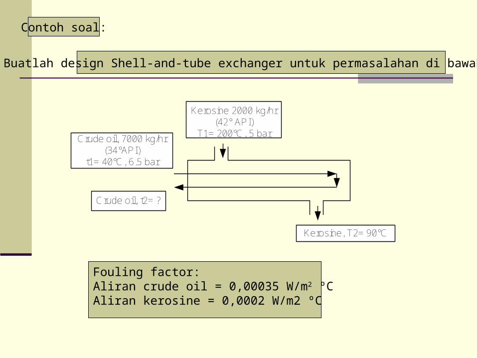
Contoh soal:
Kerosine 2000 kg/hr(42° API)
T1= 200°C, 5 bar
Kerosine, T2= 90°C
Crude oil, 7000 kg/hr(34°API)
t1= 40°C, 6.5 bar
Crude oil, t2= ?
Buatlah design Shell-and-tube exchanger untuk permasalahan di bawah ini
Fouling factor:Aliran crude oil = 0,00035 W/m2 ºCAliran kerosine = 0,0002 W/m2 ºC
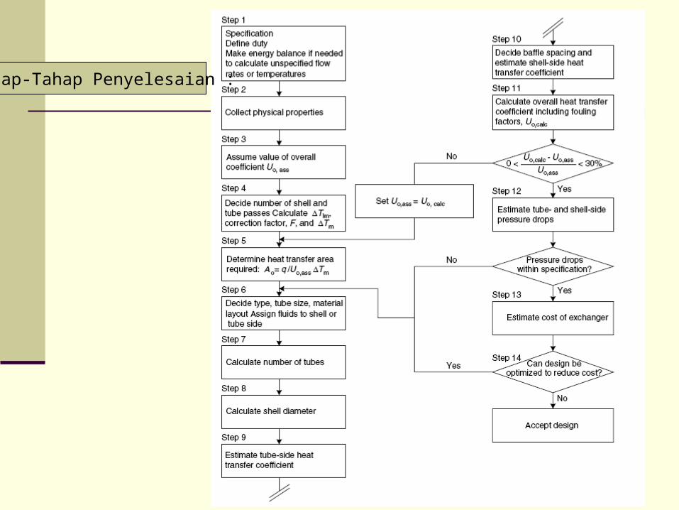
Tahap-Tahap Penyelesaian :

Spesifikasi: Pressure drop yang diizinkan untuk kedua aliran, 0.8 bar Fouling faktor, Crude oil = 0,00035 (W/m2 ºC)-1
Kerosine = 0,0002 (W/m2 ºC)-1
Temperatur rata-rata kerosine=(200+90)/2 = 145 ºC Heat capasity kerosine 42º API = 2.47 kJ/kgºC Q = (20.000/3600) x 2,47 x (200 – 90) = 1509,4 kW
Tahap 1:
Lakukan trial untuk tmean dan specific heat:Crude oil untuk tmean = tinlet Dari
t2 = 78,6 ºC dantmean =(40 + 78.6)/2 = 59,3 ºCsehingga specific heat untuk 59,3 ºC = 2,05 kJ/kgºC
4,1509)40(01,23600
700002 txbalanceenergy
Lakukan trial untuk t2 menggunakan specific heat 2,05 kJ/kgºCDidapat t2 = 78 ºC

Tahap 2 :
Penentuan Physical Propertis

Tahap 3 :
Overall coefficient
Untuk Exchanger overall coefficient berada pada range 100 sampai 300 W/m2ºC
Liat grafik 12.1 dan tabel 12.1

Grafik 12.1

Tabel 12.1
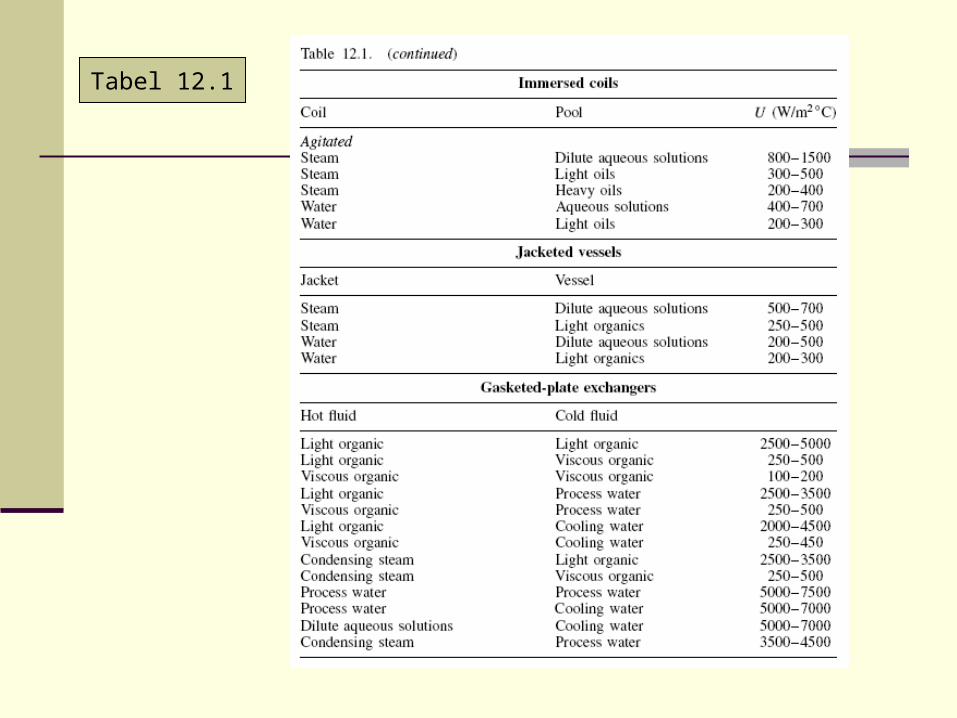
Tabel 12.1

Tahap 4 : Exchanger type and dimensions
Dimulai dengan one shell pass and 2 tube passes
CT olm 7,80
4090
78200ln
409078200
9,2
4078
90200
R
24,0
40200
4078
S
Dari grafik 12.19, Ft =0,88
Sehingga : CxT om 08,717,8088,0
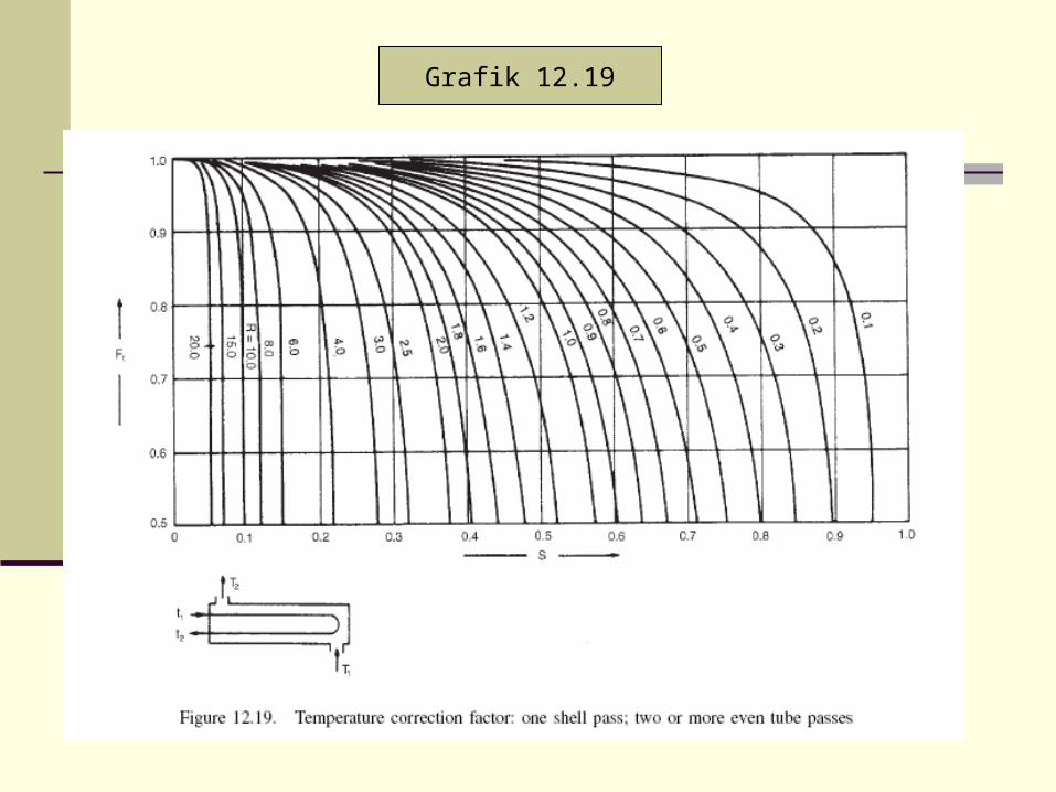
Grafik 12.19
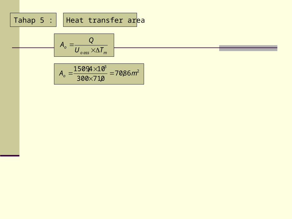
Tahap 5 : Heat transfer area
23
86,700,71300
104,1509mAo
massoo TU
QA
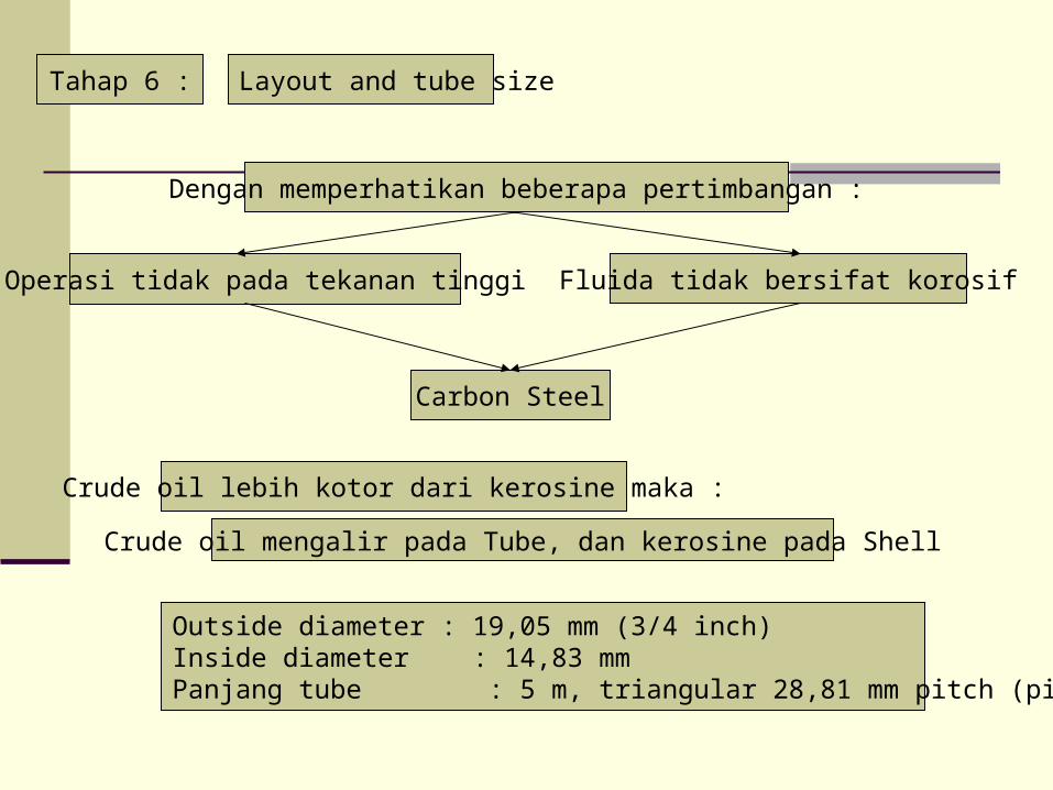
Carbon Steel
Operasi tidak pada tekanan tinggi Fluida tidak bersifat korosif
Dengan memperhatikan beberapa pertimbangan :
Tahap 6 : Layout and tube size
Crude oil lebih kotor dari kerosine maka :
Crude oil mengalir pada Tube, dan kerosine pada Shell
Outside diameter : 19,05 mm (3/4 inch)Inside diameter : 14,83 mmPanjang tube : 5 m, triangular 28,81 mm pitch (pitch/dia, = 1,25)

Tahap 7 :
Luas area tube:
Number of tube
23 2992,051005.19 m
Number of tube: 240,2372992,0/86,70 dibulatkan
Sehigga untuk 2 passes, tube per pass = 120
Tube cross-sectional area : 223 0001727,01083,144
m
Luas area per pass : 202073,00001727,0120 m
Volumetric flow : sm /0237,0820
1
3600
000.70 3
Tube-side volocity, :tu sm /14,102073,0
0237,0

Tahap 8 : Bundle and shell diameter
Dari tabel 12.4, untuk 2 tube passes, K1= 0,249, n1 = 2,207
Sehingga : mmmDb 43,0428249,0
24005,19
207,2/1
Untuk split-ring floating head exchanger, typical shell clearance dari grafik 12.10, =56 mm
Sehingga Shell inside diameter : mmDs 48456428

Tabel 12.4

Grafik 12.10

Tahap 9 : Tube-side heat transfer coefficient
33
3
103,44332102,3
1083,1414,1820Re
96,48134,0
102,31005,2Pr
33
33783,14
5000
id
L
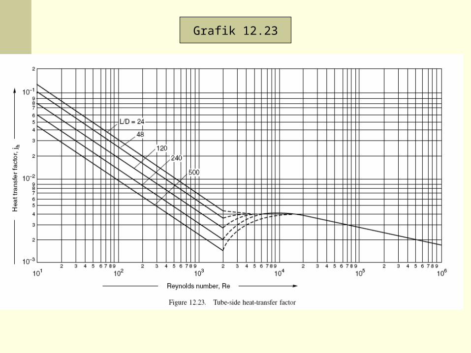
Dari grafik 12.23, didapat harga 3102,3 hj
06,5096,48)4332(102,3 33,03 Nu
CmWh oi
23
/4521083,14
134,006,50
Keadaan ini jika U0 nya 300W/m2 ºC
Grafik 12.23
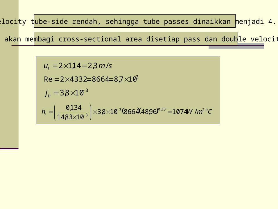
Velocity tube-side rendah, sehingga tube passes dinaikkan menjadi 4.
Ini akan membagi cross-sectional area disetiap pass dan double velocity
smut /3,214,12 3107,8866443322Re
3108,3 hj
CmWh oi
233,033
/107496,488664108,31083,14
134,0

Tahap 10 : Shell-side heat transfer coefficient
Metode Kern
Dengan 4 tube passes K1 = 0,175 n1 = 2,285
mmmDb 45,0450175,0
24005,19
285,2/1
Shell clearance = 56 mm Ds =506 mm
Trial baffle spacing = Ds/5 = 100 mm
22 01012,0116,1010050681,23
05,1981,23mmmAs
mmd e 52,1305,19917,081,2305,19
10,1 22

Volumetric flow-rate di Shell : sm /0076,0730
1
3600
000.20 3
43
3
1072,1214,171043,0
1052,1375,0730Re
05,8132,0
1043,01047,2Pr
33
Grafik 12.29 31052,4 hj
CmWh os
233,033 /150505,8214,171052,41052,13
132,0
Segmental baffle dengan 25% cut

Grafik 12.29

Tahap 11 : Overall coefficient
0002,01505
1
552
83,14
05,19ln1005,19
83,14
05,1900035,0
1074
113
oU
CmWU oo
2/386
Keadaan ini diatas initial estimasi 300 W/m2 ºC
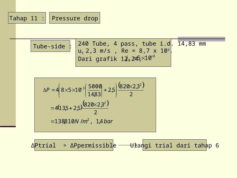
Tahap 11 : Pressure drop
Tube-side : 240 Tube, 4 pass, tube i.d. 14,83 mmut 2,3 m/s , Re = 8,7 x 10³.Dari grafik 12.24,
3105 hj
2
3,28205,2
83,14
500010584
23
P
2
3,28205,25,134
2
barmN 4,1,/810,138 2
∆Ptrial > ∆Ppermissible Ulangi trial dari tahap 6
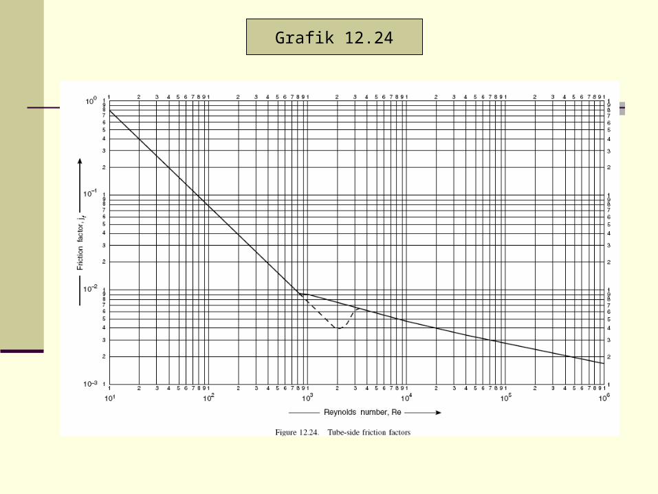
Grafik 12.24

Modifikasi design :
1. Tube velocity dikurangi.2. Koefficien heat transfer dikurangi, sehingga number of tubes harus dinaikkan untuk mengimbangi.3. ∆P proporsional dengan square velocity4. ut , proporsional terhadap number of tubes per pass,
Trial
360 Tube, 4 pass, tube i.d. 14,83 mmus 0,455 m/s , Re = 10.443 ∆Ps=0,47 bar Uo= 288 Wm-2 oC-1

• Split ring, floating head, 1 shell pass, 4 tube passes.• 360 carbon steel tubes, 5 m long, 19,05 mm o.d., 14,83 mm i.d., triangular pitch, pitch 23,8 mm.• Heat transfer area 107,7 m2 (didasarkan outside diameter)• Shell i.d., 597 mm (600 mm), baffle spaci 140 mm, 25% cut.• Tube side coefficient 680 W/m2 ºC• Shell side coefficient 1366 W/m2 ºC• Overall coefficient, estimated 288 W/m2 ºC• Overall coefficient, required 197 W/m2 ºC• Dirt / Fouling factor :
Tube-side (crude oil) 0,00035 (W/m2 ºC)-1
Shell-side (kerosine) 0,0002 (W/m2 ºC)-1
• Pressure drop :Tube-side, estimated 0,40 bar, + 0,1 for nozzles, specified 0,8 bar overallShell-side, estimated 0,45 bar, + 0,1 for nozzles, specified 0,8 bar overall
Summary
PROBLEMIDENTIFICATION
SELECTION OF BASICHEAT EXCHANGER TYPE
SELECTION OF A TENTATIVE SET OF EXCHANGER DESIGN PARAMETER
MODIFICATION OF THE DESIGN PARAMETER
RATING OF THE DESIGN:THERMAL PERFORMANCE PRESSURE DROP
EVALUATION OF THE DESIGN: Q, ∆P ACCEPTABLE?
MECHANICAL DESIGN COSTING, ETC
UNACCEPTABLE
ACCEPTABLE
THE ELEMENTS WITHIN THIS OUTLINE MAY BE DONE BY HAND OR BY COMPUTER
A procedure for the designOf the a heat exchangerComprising a tentive Selection of design parameters

FLOW RATES
FOULING FACTORS
FLUID PROPERTIES
EXCHANGER CONFIGURATION
PRESSURES
TEMPERATURES
RATING PROGRAM
1GEOMETRY CALCULATIONS
2HEAT TRANSFER CORELATIONS
3PRESSURE DROP CORELATIONS
PRESSURE DROPS
OUTLET TEMPERATURES(LENGTH FIXED)
LENGTH (DUTY FIXED)
Rating of performance

IS∆PT < ∆PT
*
AND∆PS < ∆PS
*
?
ADJUSTINTERNAL PARAMETERS
RE-RATE
ADD SHELLIN PARALLEL
RE-RATE
RE-RATE
RE-RATEADD SHELLIN PARALLEL
DECREASE SHELLDIAMETER
ADJUST INTERNALPARAMETERS TO STANDARD VALUES COUNTINUE
RATING PROGRAMINITIAL OUTPUT:LENGTH OF LARGESTDIAMETER SHELL, FEWESTTUBE PASSES, GREATESTBAFFLE SPACING
IS∆PS < ∆PS
*
AND∆PT < ∆PT
*
?
?
IS∆PS < ∆PS
*
OR∆PT < ∆PT
*
?
ISL < L*
?
NO
YES
NO
NO
NO
YES
YES
YES
Modification of design if necessary and re-rating to meet specification

Shell side flow streams (Tinker model)

Idealised shell-side flow model

Heat exchanger specification sheet

Temperature profile between hot and cold fluids

HOW TO SELECT THE OPTIMUM SHELL-AND-TUBE HEAT EXCHANGER

FLUID ALLOCATION
CORROSION Need fewer costly alloy components if the corrosive fluid is inside the tubes
FOULING Placing the fouling liquid in the tubes allows better velocity control;
Increased velocities tend to reduce fouling;
Straight tubes allow mechanical cleaning without removing the tube bundle
TEMPERATURE High temperature requires special or expensive alloy materials;
Fewer alloy components are needed when the hot fluid is placed within the tubes
PRESSURE Placing a high-pressure stream in the tubes will require fewer high-pressure components
PRESSURE DROP For the same pressure drop, higher heat-transfer coefficients are obtained on the tubeside;
A fluid with a low allowable pressure drop should generally be placed inside the tubes
VISCOSITY Higher heat-transfer rates are ordinarily obtained by placing a viscous fluid on the shell side
FLOWRATE The lower flowrate fluid on the shellside results in a more economical design. Turbulence exists on the shellside at much lower velocities than within the tubes.

CONSIDERATIONS BY THE DESIGNER
Evaluate the many variables in establishing the following characteristics of the heat exchanger:
1 Tube O.D. and length 8 Actual Pressure Drops
2 Tube Pitch 9 Shell Size
3 Number of Tube Passes 10 Fluid Distribution at the Inlet and Outlet of the Shell
4 Number of Shell Passes 11 Tube-to-tubesheet Attachement
5 Number of Baffles and Baffle Type 12 Ease of Maintenance
6 Number of Shells 13 Vibration, operating differential-expansion between shell and tubes, and other potential problem areas.
7 Fluid Velocities

TUBE SIZE AND LENGTH
* HE designs with small-diameter tubes (5/8-in to 1-in O.D.) are more economical than designs with larger tubes, because the smaller tubes provide for a more compact unit.* 5/8-in to 1-in O.D. tubes are the smallest considered for process HE, but there are some applications where smaller tubes may be better.
* HE designs with small-diameter tubes (5/8-in to 1-in O.D.) are more economical than designs with larger tubes, because the smaller tubes provide for a more compact unit.* 5/8-in to 1-in O.D. tubes are the smallest considered for process HE, but there are some applications where smaller tubes may be better.
Larger-diameter tubes are used when heavy fouling is expected, and when the inside of the tubes is to be cleaned mechanically.
Larger-diameter tubes are used when heavy fouling is expected, and when the inside of the tubes is to be cleaned mechanically.
Because tubes in the 5/8 – 1 –in-O.D. range are normally common for shell-and-tubeexchangers, tubes in these sizes are more readily available in various materials ofconstructions.
Because tubes in the 5/8 – 1 –in-O.D. range are normally common for shell-and-tubeexchangers, tubes in these sizes are more readily available in various materials ofconstructions.
The Investment per unit area of heat transfer surface is less for longer heat exchangers.Therefore, should avoid restrictions on length wherever possible.
The Investment per unit area of heat transfer surface is less for longer heat exchangers.Therefore, should avoid restrictions on length wherever possible.

TUBE PITCH OR ARRANGEMENT
Tubes are generally arranged on a triangular, square or rotated-square pitchTubes are generally arranged on a triangular, square or rotated-square pitch
Although the tube pitch can vary fir a given tube size, the designer should limitthe center-to-center spacing to the minimum, as outlined in the TEMA Standards, for good mechanical design
Although the tube pitch can vary fir a given tube size, the designer should limitthe center-to-center spacing to the minimum, as outlined in the TEMA Standards, for good mechanical design
Triangular-tube patterns provide better shellside heat-transfer coefficients in sensible-heatExchange, and provide more surface area for a given shell diameter
Triangular-tube patterns provide better shellside heat-transfer coefficients in sensible-heatExchange, and provide more surface area for a given shell diameter
Square-pitch tube patterns are generally used when mechanical cleaning of the outside of the tubes is expected; however, square-and rotated-square tube patterns provide lowerpressure drops and lower heat-transfer coefficients in most cases involving sensible heat
Square-pitch tube patterns are generally used when mechanical cleaning of the outside of the tubes is expected; however, square-and rotated-square tube patterns provide lowerpressure drops and lower heat-transfer coefficients in most cases involving sensible heat
Some spaced triangular pitches are required to facilitate lower pressure drops or reduceshellside velocities
Some spaced triangular pitches are required to facilitate lower pressure drops or reduceshellside velocities

NUMBER OF PASSES ON TUBESIDE AND SHELLSIDE
The number of tubeside or shellside passes provided in the design of an optimum HEdepends in operating temperatures, allowable pressure drops, fluid velocities, relative cost,and the experience of the designer.
One or more passes can be used on the tubeside; multiple passes are used to increase velocity and the heat-transfer rate.
In selecting the number of tubeside passes, must limit the velocity to maintain an allowable pressure drop and to avoid erosion of the tube material
The number of passes on the shellside or the configuration of the shell (one pass, two passes, split flow, divided flow, etc) is primarily a function of the operatingtemperatures, flowrates and allowable pressure drop
The number of passes on the shellside or the configuration of the shell (one pass, two passes, split flow, divided flow, etc) is primarily a function of the operatingtemperatures, flowrates and allowable pressure drop
In as much as the number of shell or tube side passes can affect the value of the correctedlog-mean-temperature difference, the size and cost of the HE are closely related to theselection of the flow configurations
In as much as the number of shell or tube side passes can affect the value of the correctedlog-mean-temperature difference, the size and cost of the HE are closely related to theselection of the flow configurations

SHELL BAFFLING
Baffles are used to direct the shellside fluid through a prescribed path, and to support the tubeswithin the bundle. Baffles are called tube supports, if this is their primary purpose. The threemost common baffle types:
SEGMENTAL BAFFLES
Provides a high degree of turbulance and good heat transfer because it directs the fluid over the tubes primarily in cross-flow;
Unless the shellside fluid is being condensed:
A horizontal baffle cut should be used to reduce accumulations of deposits at the bottom of the shell and to prevent stratification of the shellside fluid;
A vertical baffle cut is required for horizontal condensers to allow the condensate to flow freely without covering or flooding an excessive amount of tubes
Baffle cuts for segmental baffles are expressed as percentage values of the diameter or net free area. A 20%-diameter cut is considered optimum because it permits the highest heat transfer for a given pressure drop
For large HE with high flowrates, it is often more economical to omit tubes in the baffle-window area. This provides for better cross-flow, while providing support for all tubes at every baffle. The ‘no-tubes-in-the-window’ baffle design is often necessary to prevent flow-induced tube vibration.

SHELL BAFFLING (contunied …..)
MULTISEGMENTAL BAFFLES
Characterized by large open areas, this type can be used to reduce baffle spacing or to reduce cross-flow because of pressure-drop limitations
Certain types of baffles allow the fluid to flow nearly parallel to the tubes, offering a much lower pressure drop
LONGITUDINAL BAFFLES
Provides for multipass or split-flow, shellside-flow patterns
It can be welded to the shell, or sealed against it by a flex seal or other device
Sealing of the long baffle against the shell by means other than welding can be done when the pressure drop is relatively low on the shellside (less than 12 psi)