Embed Size (px)
Citation preview
International Journal of Oil, Gas and Coal Engineering 2016; 4(1-1): 1-7
http://www.sciencepublishinggroup.com/j/ogce
doi: 10.11648/j.ogce.s.2016040101.11
ISSN: 2376-7669(Print); ISSN: 2376-7677(Online)
Pressure Transient Analysis for Finite Conductivity Multi-staged Fractured Horizontal Well in Fractured-Vuggy Carbonate Reservoirs
Mingqiang Wei1, Yonggang Duan
1, Xuemei Zhou
2, Quantang Fang
1
1State Key Laboratory of Oil and Gas Reservoirs Geology and Exploitation, Southwest Petroleum University, Chengdu, Sichuan Province,
PR China 2Shell China Exploration and Production Co, Chengdu, Sichuan Province, PR China
Email address:
[email protected] (Mingqiang Wei), [email protected] (Yonggang Duan) *Corresponding author
To cite this article: Mingqiang Wei, Yonggang Duan, Xuemei Zhou, Quantang Fang. Pressure Transient Analysis for Finite Conductivity Multi-staged Fractured
Horizontal Well in Fractured-Vuggy Carbonate Reservoirs. International Journal of Oil, Gas and Coal Engineering. Special Issue: Academic
Research for Multidisciplinary. Vol. 4, No. 1-1, 2016, pp. 1-7. doi: 10.11648/j.ogce.s.2016040101.11
Received: August 12, 2015; Accepted: May 17, 2016; Published: June 30, 2016
Abstract: Transient pressure analysis has been considered as a robust method to identify the flow behaviors, estimate reservoir
parameters and hydraulic fracturing parameters. Compared with conventional clastic reservoirs, complex pore systems in
fractured–vuggy carbonate reservoirs are posing significant research challenges. Although pressure transient analysis(PTA)
models for different style wells in carbonate reservoirs have been widely studied, limited study has been conducted for
multi-fractured horizontal well (MFHW) in these reservoirs. Thus, this paper is an investigation on PTA for MFHW of
fractured-vuggy carbonate reservoirs. Based on source function theory, mirrors reflection and superposition principle,, the finite
conductive MFHW’s bottom-hole pressure solution for fractured-vuggy carbonate reservoirs is obtained by the Laplace
transform and the Stehfest inversion method. Log-log type curves are drawn by numerical algorithms and eight flow regimes are
identified. Finally the influences of sensitivity parameters such as fracture number, fracture spacing, half length of fracture,
storativity ratio, inter-porosity flow coefficient on unsteady flow behaviors of MFHW are discussed in depth.
Keywords: Fractured-Vuggy Carbonate Reservoir, Multi-fractured Horizontal Well, Finite Conductive, Transient Pressure
1. Introduction
Compared with conventional clastic reservoirs,
fractured-vuggy carbonate reservoirs are composed of matrix,
fractures, vugs systems. Among these systems, the properties
of porosity, permeability and fluid transport behaviors are
quite different, which brings a big challenge to study the fluids
flow and transport behaviors in these reservoirs [1], [2], [3].
In recent decades, many scholars have made some efforts to
study the fluids flow and transport behaviors in
fractured–vuggy reservoirs. G. Fuentes-Cruz et al. [4] studied
the transient pressure and production decline curve behaviors
for partially penetrating wells completed in fractured-vuggy
reservoirs. Camacho-Velázquez et al. [5] proposed an unsteady
flow analysis model for carbonate reservoirs, and analyzed the
transient pressure and production decline curves. Subsequently,
the transient pressure of fractured well in fractured-vuggy
reservoirs is investigated by Cai and Jia [6]. Cheng et al. [7]
used triple media model to establish the well testing model for
multi-branch horizontal wells. And the numerical well testing
method for carbonate reservoirs is studied by Corbett et al. [8].
However this method is limited for isolated cave. Gulbransen et
al. [9] propsed a multi-scale mixed finite element method for
modeling of vuggy and naturally fractured reservoirs. Wu et al.
[10], [11], [12] proposed a triple-continuum model to describe
flow in fractured rock & naturally fractured vuggy reservoirs.
Ren et al. [13] proposed a well testing model of inclined well
for fractured-vuggy carbonate reservoirs. Jia et al. [14]
developed a flowing model of well test analysis for
porous-vuggy carbonate reservoirs. After that, a analytical
model for wormholes in fractured–vuggy carbonate reservoirs
is developed by Wang et al. [15]. Chen et al. [16] used boundary
2 Mingqiang Wei et al.: Pressure Transient Analysis for Finite Conductivity Multi-staged Fractured Horizontal
Well in Fractured-Vuggy Carbonate Reservoirs
element method for modeling of fractured-vuggy reservoirs
with large-scale caves and obtained the PTA type curves. Guo
et al. [17] and Nie et al. [18] investigated the flow behavior for
modeling horizontal well production in fractured-vuggy
carbonate reservoirs. However, these aforementioned models
were mainly developed for vertical wells, fractured wells and
horizontal wells.
According to above mentioned models in fractured-vuggy
carbonate reservoirs, two main models are used to describe and
study the flow process in fractured-vuggy carbonate reservoirs:
(1) triple porosity and single permeability model [15], [19]. The
model considers the vug system as a continuum medium, treats
fracture system as pathways directly connected to the wellbore,
and considers the matrix and vug systems connect to the
fracture system. And the inter-porosity flows are considered
from the matrix and vug systems to the fracture system; (2)
triple porosity and dual permeability model [20]. This model
also considers the vug system as a continuum medium, treats
fracture system and vug system as pathways directly connected
to the wellbore and considers the inter-porosity flows to occur
between matrix, fracture and vug systems.
Although series of progress on PTA in fractured-vuggy
carbonate reservoirs have been made by using the two models,
little study on MFHW of PTA has been conducted in
fractured-vuggy carbonate reservoirs. Fortunately, many
studies on pressure behaviors of MFHW in clastic and
unconventional reservoirs have been performed in recent 20
years [21], [22], [23], [24], [25], [26], [27], which can guide to
study PTA of MFHW in fractured-vuggy carbonate reservoirs. To extend the PTA theory into MFHW in fractured-vuggy
carbonate reservoirs, a triple porosity and single permeability
model is used in this paper to investigate the transient pressure
behavior of finite conductive MFHW. Based on Source
function theory, mirrors reflection and superposition principle,
the finite conductive MFHW’s bottom-hole pressure solution
is obtained by Laplace transform and Stehfest inversion
methods. Type curves are drawn by numerical simulations and
eight flow regimes are identified. Finally the sensitivity
parameters were discussed in depth.
2. Physical Model
Generally speaking, fractured-vuggy carbonate reservoir
consists of matrix, fractures and vuggy (Fig. 1). Fluids in the
reservoir would flow into wellbore under the pressure drop
between wellbore and reservoir pressures, and the triple
porosity and sequential single permeability of MFHW flow
scheme is shown in Fig. 3.
a) Real core photo of ractured-vuggy reservoir
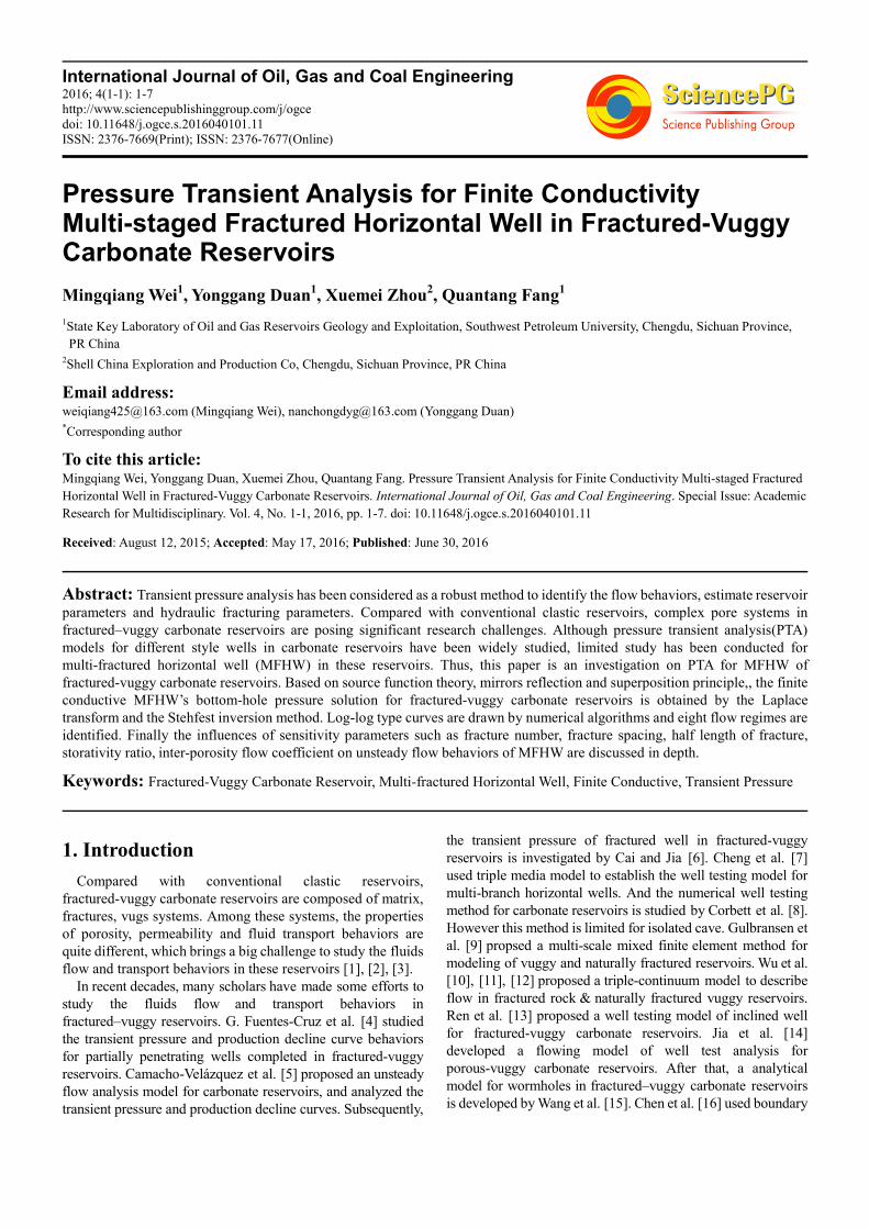
(b) Physical scheme of Naturally fractured-vuggy reservoir scheme[17]
Fig. 1. Naturally fractured-vuggy reservoir scheme.
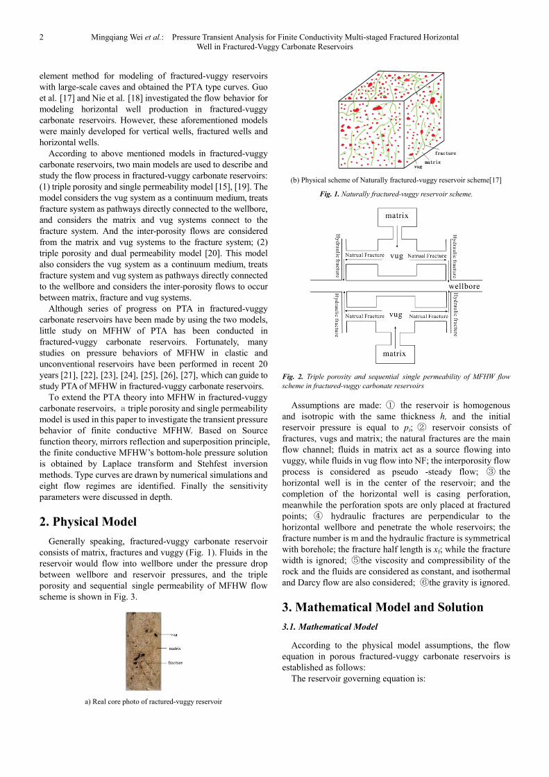
Fig. 2. Triple porosity and sequential single permeability of MFHW flow
scheme in fractured-vuggy carbonate reservoirs
Assumptions are made: ① the reservoir is homogenous
and isotropic with the same thickness h, and the initial
reservoir pressure is equal to pi; ② reservoir consists of
fractures, vugs and matrix; the natural fractures are the main
flow channel; fluids in matrix act as a source flowing into
vuggy, while fluids in vug flow into NF; the interporosity flow
process is considered as pseudo -steady flow; ③ the
horizontal well is in the center of the reservoir; and the
completion of the horizontal well is casing perforation,
meanwhile the perforation spots are only placed at fractured
points; ④ hydraulic fractures are perpendicular to the
horizontal wellbore and penetrate the whole reservoirs; the
fracture number is m and the hydraulic fracture is symmetrical
with borehole; the fracture half length is xf; while the fracture
width is ignored; ⑤the viscosity and compressibility of the
rock and the fluids are considered as constant, and isothermal
and Darcy flow are also considered; ⑥the gravity is ignored.
3. Mathematical Model and Solution
3.1. Mathematical Model
According to the physical model assumptions, the flow
equation in porous fractured-vuggy carbonate reservoirs is
established as follows:
The reservoir governing equation is:
International Journal of Oil, Gas and Coal Engineering 2016; 4(1-1): 1-7 3
( )Nf v Nf
Nf v Nf t Nv f)+ (
k k pp p p V C
tα φ
µ µ∂∆ ∇ ∆ ∆ ∆ =− ∂
(1)
The formula of interporosity flow from vug sto NFs is:
(2)
The inter flow equation from matrix to vugs is:
(3)
Taking the Laplace transform of Eqs.(1)~(3), Eqs.(4)~(6)
can be obtained, respectively:
(4)
(5)
(6)
Combining Eqs.(5) ~(6) and the following dimensionless
definitions, Eq. (4) can be written as:
(7)
In Eq.(7), the expression of u is:
(8)
All the Dimensionless definitions in the paper are as below:
Dimensionless distance:
Dimensionless wellbore storage coefficient: Dimensionless
time:
Dimensionless pressure:
The parameters in Eq. (8) are defined as follows:
Vug storage capacity ratio:
Interporosity flow coefficient from vugs to NFs:
Matrix storage capacity ratio:
Interporosity flow coefficient from matrix to vugs:
Based on Eqs.(7) and (8), the flow equation is established
by utilizing the point source function and boundary
conditions:
(9)
Furthermore, based on Eq. (9), the continuous point source
solution[28], [29] of closed top and bottom borders of
reservoirs can be obtained by the mirrors reflection and the
superposition principle:
(10)
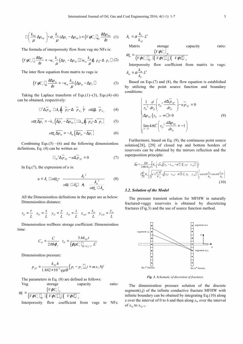
3.2. Solution of the Model
The pressure transient solution for MFHW in naturally
fractured-vuggy reservoirs is obtained by discretizing
fractures (Fig.3) and the use of source function method.
segement i,j1
segement m,j2
x
y
the ith fracture the mth fracture
segement m,n
Fig. 3. Schematic of discretion of fractures.
The dimensionless pressure solution of the discrete
segment(i,j) of the infinite conductive fracture MFHW with
infinite boundary can be obained by integrating Eq.(10) along
z over the interval of 0 to h and then along xw over the interval
of xi,j to xi,j+1.
( ) ( ) ( )v v m
t v v Nf m m vvα α
p k kV C p p p p
tφ
µ µ∂∆
= − ∆ − ∆ + ∆ − ∆∂
( ) ( )m mt m m vm
αp k
V C p pt
φµ
∂∆= − ∆ − ∆
∂
( )2
f fV NfNf V N Np p p s pλ ω∇ ∆ + ∆ − ∆ = ∆
( ) ( )v v v v Nf m m vλ λs p p p p pω ∆ = − ∆ − ∆ + ∆ − ∆
( )m m m m vs p p pω λ∆ = − ∆ − ∆
2 0D Nf Nf
p u p∇ ∆ − ∆ =
2
2
V
v Nf
mV m V
m m
u s
ss
λλ ωλω λ λ
ω λ
= + −+ + −
+
D
rr
L= D
xx
L= D
yy
L= D
zz
L= w
wD
xx
L= w
wD
yy
L=
2D
f
CC
hπ ϕ=
( ) 2
3.6
f
Nf
D
t m N V
k tt
C Lϕµ+ +
=
( )3, . ,
1.842 10
Nf
jD i j
k hp p p j m v Nf
q Bµ−= − =×
( )( ) ( ) ( )
t V
V
t t tNf m V
V C
V C V C V C
ϕω
ϕ ϕ ϕ=
+ +
2V
V
Nf
kL
kλ α=
( )( ) ( ) ( )
t m
m
t t tNf m V
V C
V C V C V C
ϕω
ϕ ϕ ϕ=
+ +
2
m
m
V
kL
kλ α=
( )
2
2
3 2
0
10
0
lim 4 1
Nf
D Nf
D DD
Nf D
Nf
D
D
d pdr u p
dr drr
p r
d pL r
drεπ
→
∆ − =
∆ → ∞ = ∆ = −
( ) ( ){( ) ( )
2 2
0
2 22 2
0 21
2
2 cos cos
D wD D wD
D
wDDD wD D wD
n D DD
qp K u x x y y
kLh s
zznK u x x y y n n
h hh
µ απ
π α π π∞
=
∆ = − − + − +
+ − − + −
∑
ɶ
4 Mingqiang Wei et al.: Pressure Transient Analysis for Finite Conductivity Multi-staged Fractured Horizontal
Well in Fractured-Vuggy Carbonate Reservoirs
(11)
In Eq.(11) is the Laplace transform of qD(xD, tD). By
writing Eq.(11) for midpoints for all discrete segments, we can
get m×n equations with (m×n+1) unknowns which are
and . To obtain the pressure
responses, one more equation can be written by assuming the
flow rate is constant:
(12)
Considering the skin effect of the fracture wall, the
relationship between fracture pressure and formation
pressure can be written as:
(13)
Since many proppants will still exist after the well
fracturing, which leads to flow resistance in the hydraulic
fractures, several previous transient pressure analysis of
MFHW assuming infinite conductivity of fractures is not
realistic[26]. Thus, the finite conductive fractures of MFHW
in carbonate reservoirs is considered
The flow equations [30] of finite conductive hydraulic
fracture ignoring the liquid compressibility can be written:
, (14)
The boundary conditions are given as follows:
(15)
(16)
In Eq.(16), the dimensionless conductive coefficient is
CfD=(kfwf)/(kLf), kf is the fracture permeability, wf is the
fracture width.
Combined with boundary conditions of Eqs.(15)~(16),
Eq.(14) can be obtained after integrating.
(17)
Eq. (17) can be rewritten based on Eqs. (11) and (13):
(18)
In order to get approximate expansion of Eq.(17), a fracture
wing is divided into n segments by discrete fracture
mechanism (see Fig3). Assuming the flow rate of each
segment is uniform distributed, Eq.(18) can be expanded by
discrete approximate method[30].
(19)
Where △x=LfD/n, xD,j is the center of the jth segment, xD,i is
the starting point of ith segment, xD,i+1 is the end point of ith
segment. n equations for n discrete segments can be
established. According to the assumption of constant flow
rate, the constraint of flow rate can be written :
(20)
Thus the n+1 equations are composed, 、
can be calculate by numerical method. When the production
rate is constant, wellbore storage and skin can be easily added
to Eq.(19) as a final step according to Duhamel’s principle
[31]:
(21)
4. Analyses of Transient Pressure
Behaviors
The unsteady pressure characteristic type curves (Fig.4) of
finite conductive MFHW for triple porosity and sequential
single permeability in fractured-vuggy reservoirs are drawn
by converting back to pwD based on Stehfest numerical
inversion [32].
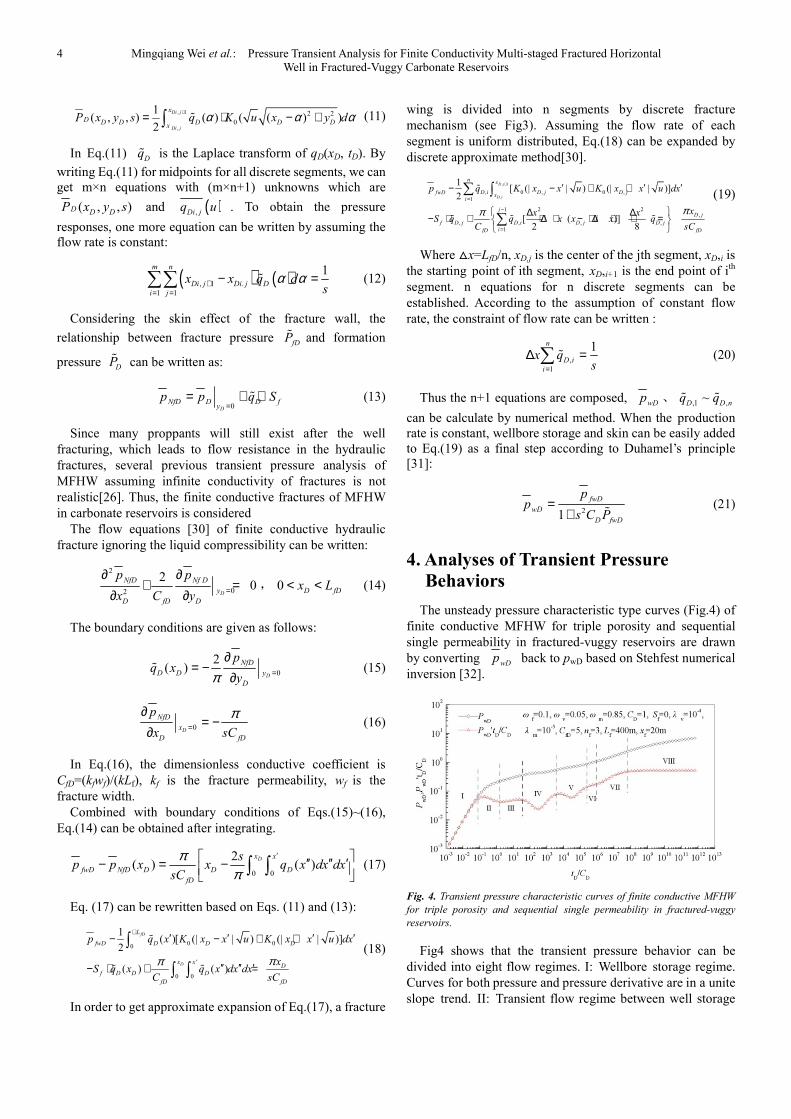
Fig. 4. Transient pressure characteristic curves of finite conductive MFHW
for triple porosity and sequential single permeability in fractured-vuggy
reservoirs.
Fig4 shows that the transient pressure behavior can be
divided into eight flow regimes. I: Wellbore storage regime.
Curves for both pressure and pressure derivative are in a unite
slope trend. II: Transient flow regime between well storage
, 1
,
2 2
0
1( , , ) ( ) ( ( ) )
2
Di j
Di j
x
D D D D D Dx
P x y s q K u x y dα α α+= ⋅ − +∫ ɶ
Dqɶ
( , , )D D DP x y s ( ),Di jq u
( ) ( ), 1 .
1 1
1m n
Di j Di j D
i j
x x q ds
α α+= =
− =∑∑ ɶ
fDPɶ
DPɶ
0D
D fNfD Dy
p p q S=
= + ⋅ɶ
2
02
20
D
NfD Nf D
y
fD DD
p p
C yx=
∂ ∂+ =
∂∂0 D fDx L< <
0
2( )
D
NfD
D D y
D
pq x
yπ =
∂= −
∂ɶ
0D
NfD
x
D fD
p
x sC
π=
∂= −
∂
0 0
2( ) ( )
Dx x
D D DfwD NfD
fD
sp p x x q x dx dx
sC
ππ
′ ′′ ′′ ′− = − ∫ ∫
0 00
'
0 0
1( )[ (| | ) (| | )]
2
( ) ( )
fD
D
L
D D DfwD
x xD
f D D D
fD fD
p q x K x x u K x x u dx
xS q x q x dx dx
C sC
ππ
+′ ′ ′ ′− − + +
′′ ′′ ′− ⋅ + =
∫
∫ ∫
ɶ
ɶ ɶ
, 1
,, 0 , 0 ,
1
2 21,
, , , ,
1
1[ (| | ) (| | )]
2
[ ( )]2 8
D i
D i
n x
D i D j D jfwDx
i
jD j
f D j D i D j D j
ifD fD
p q K x x u K x x u dx
xx xS q q x x i x q
C sC
ππ
+
=
−
=
′ ′ ′− − + +
∆ ∆− ⋅ + + ∆ ⋅ − ⋅ ∆ + ⋅ =
∑ ∫
∑
ɶ
ɶ ɶ ɶ
,
1
1n
D i
i
x qs=
∆ =∑ ɶ
wDp ,1 ,~
D D nq qɶ ɶ
21
fwD
wD
D fwD
pp
s C P=
+ ɶ
wDp
International Journal of Oil, Gas and Coal Engineering 2016; 4(1-1): 1-7 5
and early linear flow which presents a hump. III: Early linear
flow regime. The pressure derivative curve is a line with a
slope of 0.25; IV: Inter-porosity flow regime from vug to NF.
Because vug permeability is higher than NF permeability;
there is a characteristic dip. V: Inter-porosity flow regime
from matrix to vug. The pressure derivative curve is also a dip
controlled by interporosity flow from matrix system to vug
system. VI intermediate-time pseudo-radial flow regime
around individual fractures which is influenced by the
distance between hydraulic fractures. VII: Compound linear
flow which represents the linear flow normal to horizontal
well axis. VIII: Compound radial flow regime which indicates
the pressure of matrix, fracture, and vug systems have arrived
at a dynamic balance. The derivative responses of pressure
shows a flat behavior .
As is known from Eq.(19), the MFHW well testing typical
curves in carbonate reservoirs are mainly influenced by
fracture number, distance between fractures, half length of
fracture, storage and inter porosity flow.
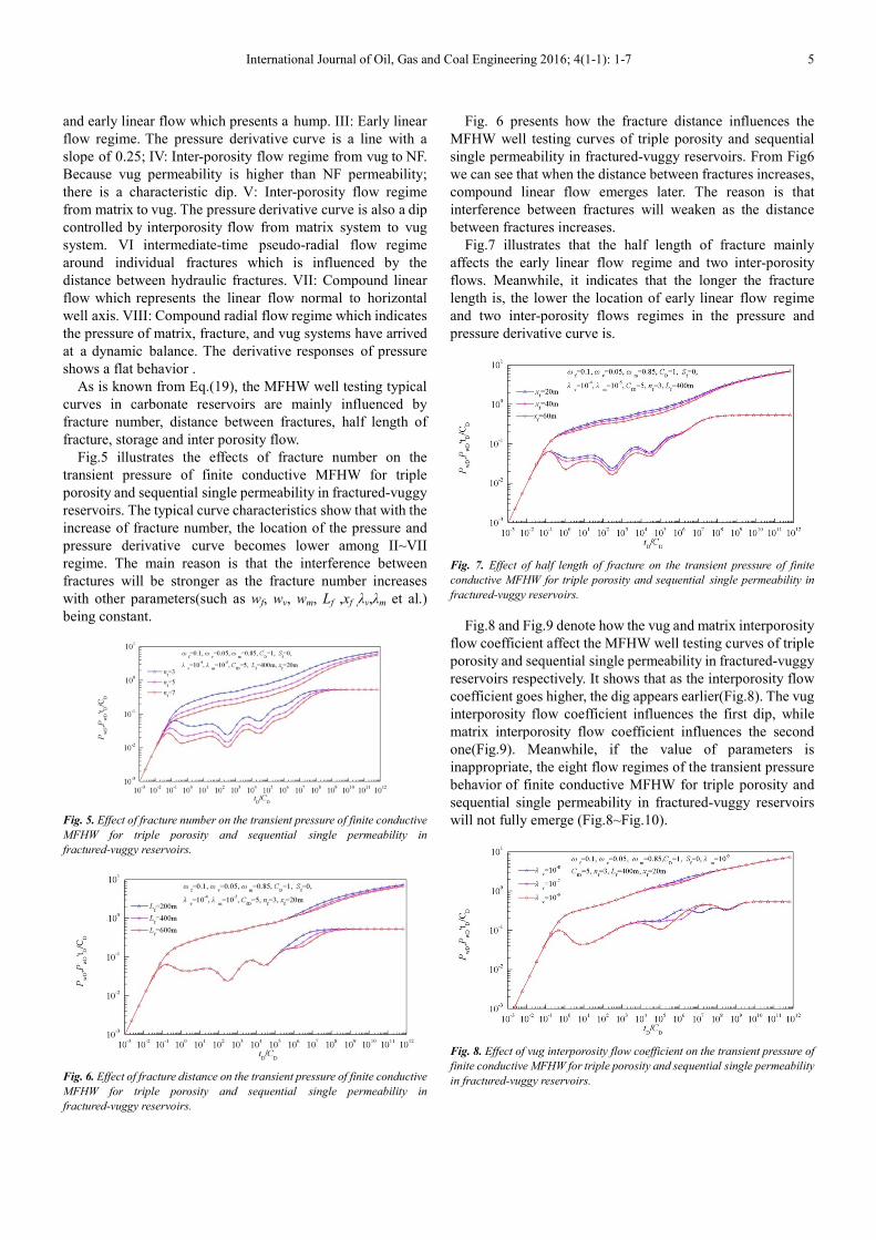
Fig.5 illustrates the effects of fracture number on the
transient pressure of finite conductive MFHW for triple
porosity and sequential single permeability in fractured-vuggy
reservoirs. The typical curve characteristics show that with the
increase of fracture number, the location of the pressure and
pressure derivative curve becomes lower among II~VII
regime. The main reason is that the interference between
fractures will be stronger as the fracture number increases
with other parameters(such as wf, wv, wm, Lf ,xf ,λv,λm et al.)
being constant.
Fig. 5. Effect of fracture number on the transient pressure of finite conductive
MFHW for triple porosity and sequential single permeability in
fractured-vuggy reservoirs.
Fig. 6. Effect of fracture distance on the transient pressure of finite conductive
MFHW for triple porosity and sequential single permeability in
fractured-vuggy reservoirs.
Fig. 6 presents how the fracture distance influences the
MFHW well testing curves of triple porosity and sequential
single permeability in fractured-vuggy reservoirs. From Fig6
we can see that when the distance between fractures increases,
compound linear flow emerges later. The reason is that
interference between fractures will weaken as the distance
between fractures increases.
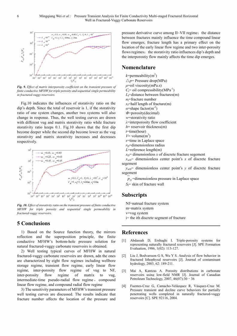
Fig.7 illustrates that the half length of fracture mainly
affects the early linear flow regime and two inter-porosity
flows. Meanwhile, it indicates that the longer the fracture
length is, the lower the location of early linear flow regime
and two inter-porosity flows regimes in the pressure and
pressure derivative curve is.
Fig. 7. Effect of half length of fracture on the transient pressure of finite
conductive MFHW for triple porosity and sequential single permeability in
fractured-vuggy reservoirs.
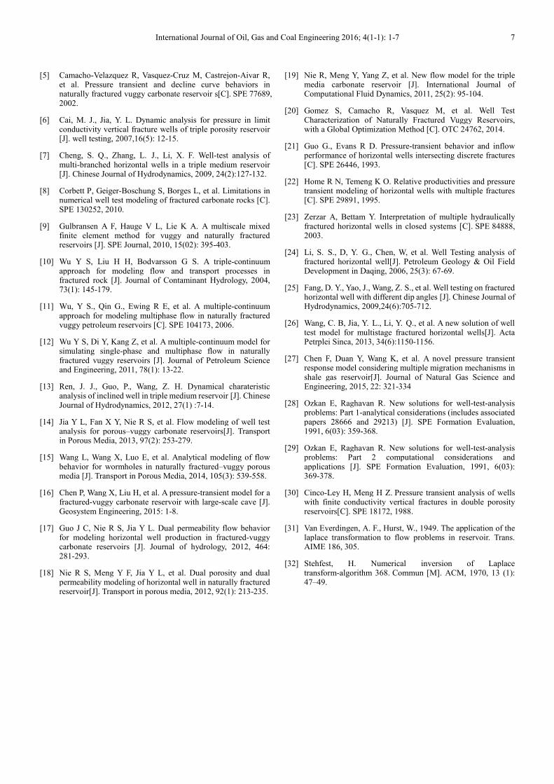
Fig.8 and Fig.9 denote how the vug and matrix interporosity
flow coefficient affect the MFHW well testing curves of triple
porosity and sequential single permeability in fractured-vuggy
reservoirs respectively. It shows that as the interporosity flow
coefficient goes higher, the dig appears earlier(Fig.8). The vug
interporosity flow coefficient influences the first dip, while
matrix interporosity flow coefficient influences the second
one(Fig.9). Meanwhile, if the value of parameters is
inappropriate, the eight flow regimes of the transient pressure
behavior of finite conductive MFHW for triple porosity and
sequential single permeability in fractured-vuggy reservoirs
will not fully emerge (Fig.8~Fig.10).
Fig. 8. Effect of vug interporosity flow coefficient on the transient pressure of
finite conductive MFHW for triple porosity and sequential single permeability
in fractured-vuggy reservoirs.
6 Mingqiang Wei et al.: Pressure Transient Analysis for Finite Conductivity Multi-staged Fractured Horizontal
Well in Fractured-Vuggy Carbonate Reservoirs
Fig. 9. Effect of matrix interporosity coefficient on the transient pressure of
finite conductive MFHW for triple porosity and sequential single permeability
in fractured-vuggy reservoirs.
Fig.10 indicates the influences of storativity ratio on the
dip’s depth. Since the total of reservoir is 1, if the storativity
ratio of one system changes, another two systems will also
change in response. Thus, the well testing curves are drawn
with different vug and matrix storativity ratio while fracture
storativity ratio keeps 0.1. Fig.10 shows that the first dip
become deeper while the second dip become lower as the vug
storativity and matrix storativity increases and decreases
respectively.
Fig. 10. Effect of storativity ratio on the transient pressure of finite conductive
MFHW for triple porosity and sequential single permeability in
fractured-vuggy reservoirs.
5 Conclusions
1) Based on the Source function theory, the mirrors
reflection and the superposition principle, the finite
conductive MFHW’s bottom-hole pressure solution for
natural fractured-vuggy carbonate reservoirs is obtained.
2) Well testing typical curves of MFHW in natural
fractured-vuggy carbonate reservoirs are drawn, adn the ones
are characterized by eight flow regimes including wellbore
storage regime, transient flow regime, early linear flow
regime, inter-porosity flow regime of vug to NF,
inter-porosity flow regime of matrix to vug,
intermediate-time pseudo-radial flow regime, compound
linear flow regime, and compound radial flow regime
3) The sensitivity parameters of MFHW’s transient pressure
well testing curves are discussed. The results indicate that
fracture number affects the location of the pressure and
pressure derivative curve among II~VII regime;the distance
between fractures mainly influence the time compound linear
flow emerges; fracture length has a primary effect on the
location of the early linear flow regime and two inter-porosity
flows regimes;the storativity ratio influences dip’s depth and
the interporostiy flow mainly affects the time dip emerges.
Nomenclature
k=permeability(m2)
△p= Pressure drop(MPa)
µ=oil viscosity(mPa.s)
Ct= oil compressibility(MPa-1
)
Lf=distance between fractures(m)
nf=fracture number
xf=half length of fracture(m)
α=shape factor(m-2
)
Φ=porosity(decimal)
w=storativity ratio
λ=interporosity flow coefficient
h= reservoir thickness(m)
t=time(hour)
V= volume(m3)
s=time in Laplace space
rD=dimensionless radius
L=reference length(m)
xD= dimensionless x of discrete fracture segement
xwD= dimensionless center point’s x of discrete fracture
segement
ywD= dimensionless center point’s y of discrete fracture
segement
=dimensionless pressure in Laplace space
Sf= skin of fracture wall
Subscripts
Nf=natrual fracture system
m=matrix system
v=vug system
i= the ith discrete segment of fracture
References
[1] Abdassah D, Ershaghi I. Triple-porosity systems for representing naturally fractured reservoirs [J]. SPE Formation Evaluation, 1986, 1(02): 113-127.
[2] Liu J, Bodvarsson G S, Wu Y S. Analysis of flow behavior in fractured lithophysal reservoirs [J]. Journal of contaminant hydrology, 2003, 62: 189-211.
[3] Mai A, Kantzas A. Porosity distributions in carbonate reservoirs using low-field NMR [J]. Journal of Canadian Petroleum Technology, 2007, 46(07):30–36
[4] Fuentes-Cruz G, Camacho-Velázquez R, Vásquez-Cruz M. Pressure transient and decline curve behaviors for partially penetrating wells completed in naturally fractured-vuggy reservoirs [C]. SPE 92116, 2004.
Dp
International Journal of Oil, Gas and Coal Engineering 2016; 4(1-1): 1-7 7
[5] Camacho-Velazquez R, Vasquez-Cruz M, Castrejon-Aivar R, et al. Pressure transient and decline curve behaviors in naturally fractured vuggy carbonate reservoir s[C]. SPE 77689, 2002.
[6] Cai, M. J., Jia, Y. L. Dynamic analysis for pressure in limit conductivity vertical fracture wells of triple porosity reservoir [J]. well testing, 2007,16(5): 12-15.
[7] Cheng, S. Q., Zhang, L. J., Li, X. F. Well-test analysis of multi-branched horizontal wells in a triple medium reservoir [J]. Chinese Journal of Hydrodynamics, 2009, 24(2):127-132.
[8] Corbett P, Geiger-Boschung S, Borges L, et al. Limitations in numerical well test modeling of fractured carbonate rocks [C]. SPE 130252, 2010.
[9] Gulbransen A F, Hauge V L, Lie K A. A multiscale mixed finite element method for vuggy and naturally fractured reservoirs [J]. SPE Journal, 2010, 15(02): 395-403.
[10] Wu Y S, Liu H H, Bodvarsson G S. A triple-continuum approach for modeling flow and transport processes in fractured rock [J]. Journal of Contaminant Hydrology, 2004, 73(1): 145-179.
[11] Wu, Y S., Qin G., Ewing R E, et al. A multiple-continuum approach for modeling multiphase flow in naturally fractured vuggy petroleum reservoirs [C]. SPE 104173, 2006.
[12] Wu Y S, Di Y, Kang Z, et al. A multiple-continuum model for simulating single-phase and multiphase flow in naturally fractured vuggy reservoirs [J]. Journal of Petroleum Science and Engineering, 2011, 78(1): 13-22.
[13] Ren, J. J., Guo, P., Wang, Z. H. Dynamical charateristic analysis of inclined well in triple medium reservoir [J]. Chinese Journal of Hydrodynamics, 2012, 27(1) :7-14.
[14] Jia Y L, Fan X Y, Nie R S, et al. Flow modeling of well test analysis for porous–vuggy carbonate reservoirs[J]. Transport in Porous Media, 2013, 97(2): 253-279.
[15] Wang L, Wang X, Luo E, et al. Analytical modeling of flow behavior for wormholes in naturally fractured–vuggy porous media [J]. Transport in Porous Media, 2014, 105(3): 539-558.
[16] Chen P, Wang X, Liu H, et al. A pressure-transient model for a fractured-vuggy carbonate reservoir with large-scale cave [J]. Geosystem Engineering, 2015: 1-8.
[17] Guo J C, Nie R S, Jia Y L. Dual permeability flow behavior for modeling horizontal well production in fractured-vuggy carbonate reservoirs [J]. Journal of hydrology, 2012, 464: 281-293.
[18] Nie R S, Meng Y F, Jia Y L, et al. Dual porosity and dual permeability modeling of horizontal well in naturally fractured reservoir[J]. Transport in porous media, 2012, 92(1): 213-235.
[19] Nie R, Meng Y, Yang Z, et al. New flow model for the triple media carbonate reservoir [J]. International Journal of Computational Fluid Dynamics, 2011, 25(2): 95-104.
[20] Gomez S, Camacho R, Vasquez M, et al. Well Test Characterization of Naturally Fractured Vuggy Reservoirs, with a Global Optimization Method [C]. OTC 24762, 2014.
[21] Guo G., Evans R D. Pressure-transient behavior and inflow performance of horizontal wells intersecting discrete fractures [C]. SPE 26446, 1993.
[22] Home R N, Temeng K O. Relative productivities and pressure transient modeling of horizontal wells with multiple fractures [C]. SPE 29891, 1995.
[23] Zerzar A, Bettam Y. Interpretation of multiple hydraulically fractured horizontal wells in closed systems [C]. SPE 84888, 2003.
[24] Li, S. S., D, Y. G., Chen, W, et al. Well Testing analysis of fractured horizontal well[J]. Petroleum Geology & Oil Field Development in Daqing, 2006, 25(3): 67-69.
[25] Fang, D. Y., Yao, J., Wang, Z. S., et al. Well testing on fractured horizontal well with different dip angles [J]. Chinese Journal of Hydrodynamics, 2009,24(6):705-712.
[26] Wang, C. B, Jia, Y. L., Li, Y. Q., et al. A new solution of well test model for multistage fractured horizontal wells[J]. Acta Petrplei Sinca, 2013, 34(6):1150-1156.
[27] Chen F, Duan Y, Wang K, et al. A novel pressure transient response model considering multiple migration mechanisms in shale gas reservoir[J]. Journal of Natural Gas Science and Engineering, 2015, 22: 321-334
[28] Ozkan E, Raghavan R. New solutions for well-test-analysis problems: Part 1-analytical considerations (includes associated papers 28666 and 29213) [J]. SPE Formation Evaluation, 1991, 6(03): 359-368.
[29] Ozkan E, Raghavan R. New solutions for well-test-analysis problems: Part 2 computational considerations and applications [J]. SPE Formation Evaluation, 1991, 6(03): 369-378.
[30] Cinco-Ley H, Meng H Z. Pressure transient analysis of wells with finite conductivity vertical fractures in double porosity reservoirs[C]. SPE 18172, 1988.
[31] Van Everdingen, A. F., Hurst, W., 1949. The application of the laplace transformation to flow problems in reservoir. Trans. AIME 186, 305.
[32] Stehfest, H. Numerical inversion of Laplace transform-algorithm 368. Commun [M]. ACM, 1970, 13 (1): 47–49.


![Characterization of Natural Vuggy Fractured Porous Medium ... · movement which impact reservoir characterization, and ultimately, production performance and total recovery [4]. Naturally](https://img.pdfslide.net/doc/110x75/5f169d8344dd477bcf4379c9/characterization-of-natural-vuggy-fractured-porous-medium-movement-which-impact.jpg)