Embed Size (px)
Citation preview

Proceedings of the 2nd
International Conference on
Machining and Measurements of Sculptured Surfaces Kraków, 20 – 22 September 2000
_________________________________________________________________________
PRIMARY RESARCH ON HYBRID EROSION
MACHINING PROCESSES
M. CHUCHRO, M.ZYBURA-SKRABALAK, A. RUSZAJ, J. CZEKAJ,
S. SKOCZYPIEC, G. SKRABALAK The Institute of Metal Cutting, Kraków, Poland
Keywords: electrochemical machining, electroerosion machining, laser beam,
abrasive grains, ultrasonic vibrations, hybrid machining
Abstract
Electrodischarge and electrochemical machining are modified for special
application in Micromachining and Microfinishing operations. In the paper the test
stands for electrochemical micromachining supported by laser beam (ECLMM),
electrodischarge machining in mixture of dielectric and powder (AEDM) and
electrodischarge machining supported by electrode-tool ultrasonic vibrations
(USEDM) are presented. Using these test-stands the primary experimental test have
been carried out. Results of these test for USEDM have been described in the paper.
The discussed idea of test-stands for ECLMM, AEDM and USEDM will be applied
in electrochemical and electrodischarge special machine-tools designed and
produced at the Institute of Metal Cutting.
1 INTRODUCTION
The electrochemical and electrodischarge machining processes are widely
applied in industry. These processes are applied for machining details made of
difficult for cutting metals, alloys and composites [Rajurkar et al. 1999]. However
in many cases electrodischarge and electrochemical machining are not enough
efficient and accurate. In order to solve this problem one can introduce additional
factors, which can support the main electrochemical or electrodischarge processes.
In practice one can distinguished the following processes [McGeough, De Silva
1996]: electrodischarge process supported by electrochemical dissolution,
electrodischarge process supported by ultrasonic vibration, electrodischarge
process carried out in mixture of dielectric and powder (for instance silicon),
electrochemical or electrodischarge grinding, electrochemical machining supported
by ultrasonic vibration or local laser beam heating. One of very important
directions of development in manufacturing is small part machining
(Micromachining) and surface smoothing (Microfinishing). Below the equipment
566 Kraków, 20-22 September 2000
for electrochemical machining assisted by laser beam, electrodischarge machining
assisted by ultrasonic vibrations and electrodischarge machining in mixture of
dielectric and powder will be presented. The first two processes can be applied
efficiently for micromachining operations. The last one is mainly applied for
microfinishing operations.
2 ELECTROCHEMICAL MACHINING ASSISTED BY LASER BEAM
(ECLMM)
One of the main problems in electrochemical small surfaces machining is
localisation of dissolution process. The efficient way of solving this problem is
local heating by laser beam the area of material allowance, which should be
removed. As it has been proved the local heating by laser beam makes it possible
[Davydov 1994]:
to increase (10 – 100 times) the velocity of dissolution or deposition coating
processes,
to localise the dissolution process on the small area,
to carry out the dissolution or deposition processes in areas difficult to reach
and machine with cutting tools,
to machine materials difficult for electrochemical machining (for instance
semiconductors).
In order to receive the satisfactory dissolution or deposition process,
localisation the influence of laser beam should be concentrated only in the
machined area. It is possible when process parameters are optimal. In process
parameters optimisation it should be taken into account, that as a result of laser
beam influence the potential of deposition or dissolution, velocity of
electrochemical reactions, rate of diffusion processes in boundary layer, current
efficiency, level of material passivation, are changed. During electrochemical
machining assisted with laser beam, the dependence of interelectrode voltage,
electrolyte and machined material chemical composition and physical properties on
rate of dissolution process is different than in classical case.
From above presented considerations it results that universal test stand
should have possibility of changing the following process parameters:
interelectrode voltage (pulse or constant),
power of laser beam,
time of pulse and pause between pulses,
dimensions of laser beam spot on machined surface,
relative displacement of laser beam and machined surface (in x, y and z axis),
electrolyte discharge,
electrolyte properties,
MMSS’2000 567
distance between cathode and anode.
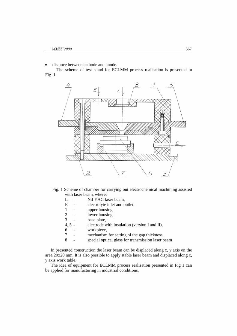
The scheme of test stand for ECLMM process realisation is presented in
Fig. 1.
Fig. 1 Scheme of chamber for carrying out electrochemical machining assisted
with laser beam, where:
L - Nd-YAG laser beam,
E - electrolyte inlet and outlet,
1 - upper housing,
2 - lower housing,
3 - base plate,
4, 5 - electrode with insulation (version I and II),
6 - workpiece,
7 - mechanism for setting of the gap thickness,
8 - special optical glass for transmission laser beam
In presented construction the laser beam can be displaced along x, y axis on the
area 20x20 mm. It is also possible to apply stable laser beam and displaced along x,
y axis work table.
The idea of equipment for ECLMM process realisation presented in Fig 1 can
be applied for manufacturing in industrial conditions.

568 Kraków, 20-22 September 2000
3. ELECTRODISCHARGE MACHINING IN THE MIXTURE OF
DIELECTRIC AND POWDER (AEDM)
Technological indicators of electrodischarge machining process, metal removal
rate, surface quality, surface roughness and number of cracks, depend mainly on
power and energy of electrical discharges. The efficient way of decreasing number
of cracks and surface roughness and generally improve surface quality is
electrodischarge machining using the mixture of dielectric and powder of silicon,
graphite, aluminium or other materials [Naruniya et al. 1989; Mohri 1991; Uno,
Okada 1997].
The improvement of surface quality results from the better electrical discharge
distribution on machined surface. Characteristic of this distribution depends on
interelectrode gap thickness, which is higher in case of machining in dielectric with
powder. Higher value of interelectrode gap thickness is the reason of the fact that
discharges are more stable and influence larger area of machined surface. The
comparison of surface roughness received in dielectric and its mixture with silicon
powder is presented in Fig. 2.
Fig. 2 Relationship between surface roughness parameter and surface of machined detail
[Kobayashi 1995]; where: 1 – case of machining in clear dielectric, 2 – case of
machining in mixture of dielectric and silicon powder
The results of machining depend on classical electrodischarge process
parameters (pulse energy and power, time of pulse and time of pause) as well as on
Ra [m]
F [cm2]
2
1

MMSS’2000 569
properties of mixture of dielectric and powder. The properties of above mentioned
mixture depend on:
sort of dielectric (water based or hydrocarbon based dielectric)
sort of material powder,
dimensions and shape of powder grains,
powder grain concentration,
uniformity of powder grain concentration.
In order to check this process in practice the electrodischarge machine tools
produced at the Institute of Metal Cutting have been equipped with a special
portable unit for dielectric mixture with powder preparing and putting it into
machined area.
The scheme of this unit is presented in Fig. 3. It can co-operate with any
electrodischarge machine - tool, especially with electrodischarge machine tool type
EDEA 16.
Fig. 3 Scheme of portable unit of dielectric and powder mixture circulation; where: 1 –
pump for dielectric and powder mixing, 2 – tank of dielectric and powder mixture, 3
– working fluid inlets, 4 – working fluid outlet, pump for supplying the machining
area with dielectric and powder mixture, 5 – pump for supplying fluid into the
interelectrode gap, 6 - working chamber, 7 – tank for waste working fluid
570 Kraków, 20-22 September 2000
It has been assumed that as a working fluid can be applied:
deionised water,
hydrocarbon based dielectric,
mixture of above mentioned liquids with different powders.
As a powder can be applied grains of graphite, Al, Si and SiC with sizes from 5
to 70 m. In order to prepare the mixture, the some amount of powder and
dielectric liquid is put into a tank. Then, pump (1) force liquid circulation (see Fig.
3) what helps to have a uniform mixture of fluid and powder, which is then pump
to machining area.
The primary tests with silicon powder and hydrocarbon based dielectric have
proved that it is possible to decrease surface roughness parameter about 20 – 30 %
in comparison to machining in clean dielectric. The idea of equipment for
providing the EDM process in the mixture of dielectric with powder can be applied
in industrial conditions.
4. ELECTRODISCHARGE MACHINING SUPPORTED BY ULTRASONIC
VIBRATIONS (USEDM)
In electrodischarge process the material allowance is removed as result of
melting and evaporating machined material during electrical discharges. The mean
temperature in electrical discharge channel is about 8 000 – 12 000 K [Albiński et
al. 1995]. The heat is transported from electrical discharge channel to machined
material and in a lesser extended to the electrode – tool. The products of this
process should be removed during pause between successive pulses from
interelectrode area. One of the efficient ways of improving the process of erosion
products transportation from interelectrode area is to apply the ultrasonic vibration
of electrode or workpiece [Lju Inczun, Du Sonjan 1986; Kremer et al. 1991; Zhixin
et al. 1997; Egashira, Masuzawa 1999]. In order to modernise one of
electrodischarge machine-tool worked out at the Institute of Metal Cutting, the
necessary investigations have been undertaken. Their results will be presented
below.
At first the special ultrasonic head has been designed and manufactured. The
amplitude of ultrasonic vibrations is changed together with power of vibrations
from 2 to 11 m. The scheme of test stand for ultrasonically assisted
electrodischarge machining is presented in Fig. 4.
MMSS’2000 571
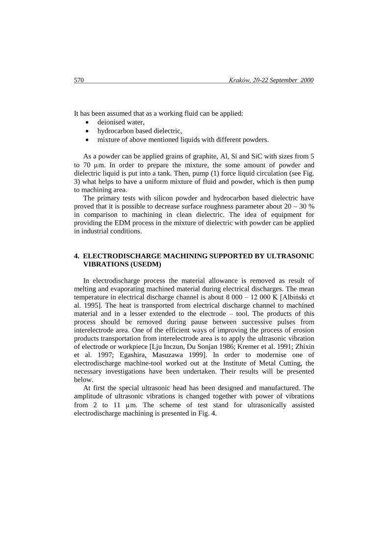
Fig. 4 Scheme of test-stand for ultrasonically assisted electrodischarge process; where: 1 –
head of machine – tool EDEA 16, 2 - ultrasonic head, 3 – ultrasonic generator, 4 –
generator of electric pulses UZSD 40Z, 5 – working chamber, 6 – workpiece table, 7
– workpiec handle, 8 – workpiece, 9 – electrode tool, 10 – oscilloscope, 11 -
computer for voltage and current registration.
Using above presented equipment the primary tests have been carried out. Their
results are presented below.
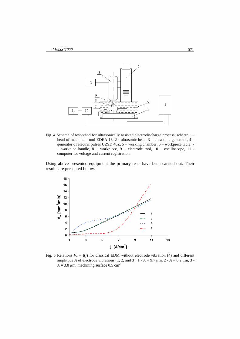
Fig. 5 Relations Vw = f(j) for classical EDM without electrode vibration (4) and different
amplitude A of electrode vibrations (1, 2, and 3): 1 - A = 9.7 m, 2 - A = 6.2 m, 3 -
A = 3.8 m, machining surface 0.5 cm2
0
2
4
6
8
10
12
14
16
18
1 3 5 7 9 11 13
j [A/cm2]
Vw [
mm
3/m
in]
1
2
3
4
572 Kraków, 20-22 September 2000
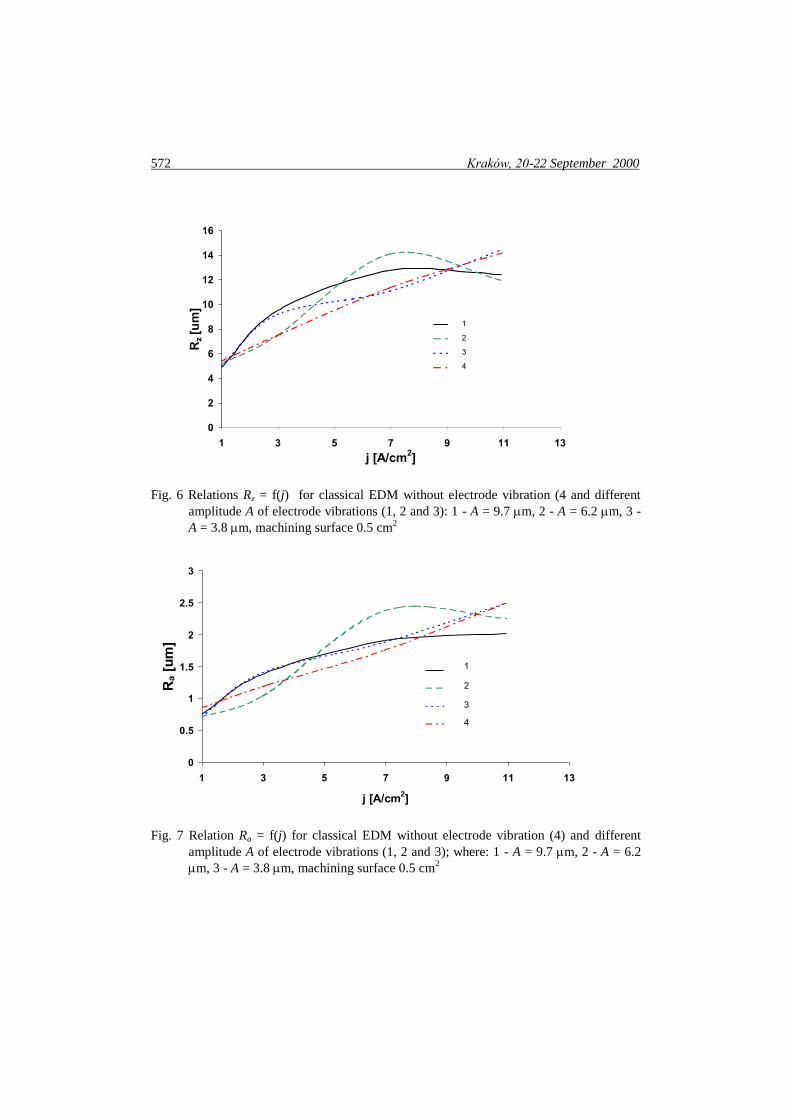
Fig. 6 Relations Rz = f(j) for classical EDM without electrode vibration (4 and different
amplitude A of electrode vibrations (1, 2 and 3): 1 - A = 9.7 m, 2 - A = 6.2 m, 3 -
A = 3.8 m, machining surface 0.5 cm2
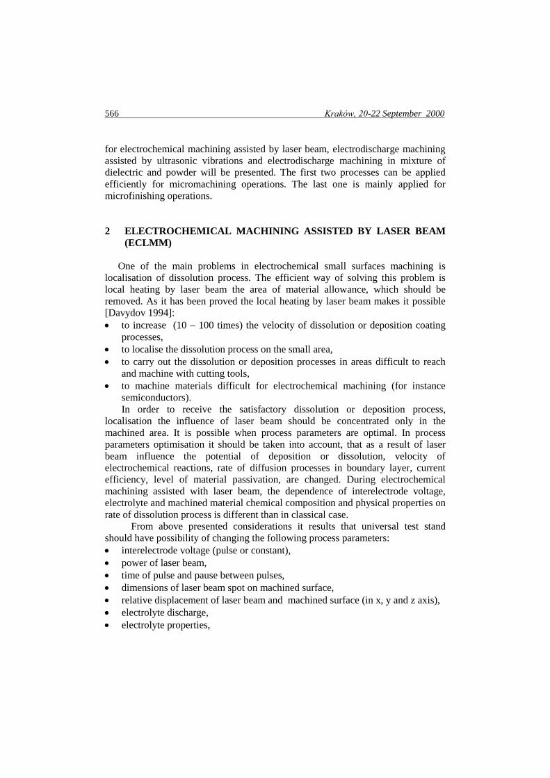
Fig. 7 Relation Ra = f(j) for classical EDM without electrode vibration (4) and different
amplitude A of electrode vibrations (1, 2 and 3); where: 1 - A = 9.7 m, 2 - A = 6.2
m, 3 - A = 3.8 m, machining surface 0.5 cm2
0
0.5
1
1.5
2
2.5
3
1 3 5 7 9 11 13
j [A/cm2]
Ra [
um
]
1
2
3
4
0
2
4
6
8
10
12
14
16
1 3 5 7 9 11 13
j [A/cm2]
Rz [u
m]
1
2
3
4

MMSS’2000 573
Fig. 8 Relation Vw = f(P) ) for different mean current density; 1 - j = 1 A/cm
2, 2 - j = 3
A/cm2, 3 - j = 7 A/cm
2, 4 - j = 11 A/cm
2, P – power of ultrasonic vibrations
Fig. 9 Relation Ra = f(P) ) for different mean current density: 1 - j = 1 A/cm
2, 2 - j = 3
A/cm2, 3 - j = 7 A/cm
2, 4 - j = 11 A/cm
2, P – power of ultrasonic vibrations
0
2
4
6
8
10
12
14
16
50 70 90 110 130 150 170
P [W]
Vw [
mm
3/m
in]
1
2
3
4
0
0.5
1
1.5
2
2.5
3
50 70 90 110 130 150 170
P [W]
Ra [
um
] 1
2
3
4

574 Kraków, 20-22 September 2000
Fig. 10 Relations Rz = f(P) for different mean current density: 1 - j = 1 A/cm2, 2 - j = 3
A/cm2, 3 - j = 7 A/cm
2, 4 - j = 11 A/cm
2, P – power of ultrasonic vibrations
Fig. 11 Photograph of initial sample surface after grinding machining
(Magnification 300 times)
0
2
4
6
8
10
12
14
16
50 70 90 11 0 1 30 15 0 17 0
P [W ]
Rz [
um
]
1
2
3
4
MMSS’2000 575
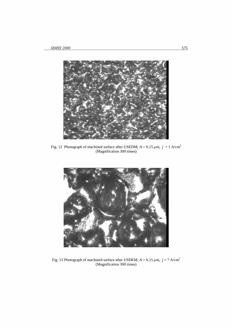
Fig. 12 Photograph of machined surface after USEDM; A = 6.15 m, j = 1 A/cm2
(Magnification 300 times)
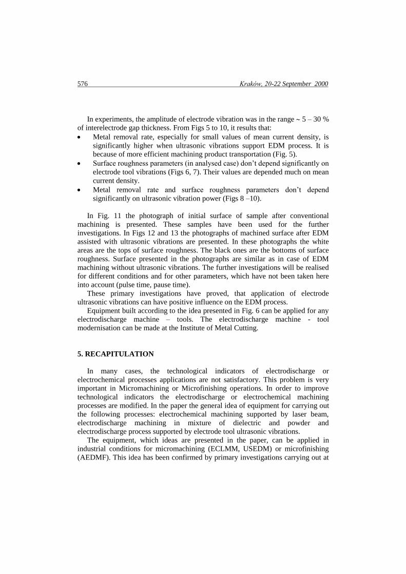
Fig. 13 Photograph of machined surface after USDEM; A = 6.15 m, j = 7 A/cm
2
(Magnification 300 times)
576 Kraków, 20-22 September 2000
In experiments, the amplitude of electrode vibration was in the range 5 – 30 %
of interelectrode gap thickness. From Figs 5 to 10, it results that:
Metal removal rate, especially for small values of mean current density, is
significantly higher when ultrasonic vibrations support EDM process. It is
because of more efficient machining product transportation (Fig. 5).
Surface roughness parameters (in analysed case) don’t depend significantly on
electrode tool vibrations (Figs 6, 7). Their values are depended much on mean
current density.
Metal removal rate and surface roughness parameters don’t depend
significantly on ultrasonic vibration power (Figs 8 –10).
In Fig. 11 the photograph of initial surface of sample after conventional
machining is presented. These samples have been used for the further
investigations. In Figs 12 and 13 the photographs of machined surface after EDM
assisted with ultrasonic vibrations are presented. In these photographs the white
areas are the tops of surface roughness. The black ones are the bottoms of surface
roughness. Surface presented in the photographs are similar as in case of EDM
machining without ultrasonic vibrations. The further investigations will be realised
for different conditions and for other parameters, which have not been taken here
into account (pulse time, pause time).
These primary investigations have proved, that application of electrode
ultrasonic vibrations can have positive influence on the EDM process.
Equipment built according to the idea presented in Fig. 6 can be applied for any
electrodischarge machine – tools. The electrodischarge machine - tool
modernisation can be made at the Institute of Metal Cutting.
5. RECAPITULATION
In many cases, the technological indicators of electrodischarge or
electrochemical processes applications are not satisfactory. This problem is very
important in Micromachining or Microfinishing operations. In order to improve
technological indicators the electrodischarge or electrochemical machining
processes are modified. In the paper the general idea of equipment for carrying out
the following processes: electrochemical machining supported by laser beam,
electrodischarge machining in mixture of dielectric and powder and
electrodischarge process supported by electrode tool ultrasonic vibrations.
The equipment, which ideas are presented in the paper, can be applied in
industrial conditions for micromachining (ECLMM, USEDM) or microfinishing
(AEDMF). This idea has been confirmed by primary investigations carrying out at
MMSS’2000 577
the Institute of Metal Cutting and will be applied in electrochemical and
electrodischarge special machine – tools designed and produced at the Institute of
Metal Cutting.
AKNOWLEDGEMENTS
The Authors would like to thank the European Commission for supporting the
co-operation between the Edinburgh University, Glasgow Caledonian University,
Warsaw Technical University, PHILIPS, KALTEX and the Institute of Metal
Cutting by funding the Concerted Action Contract No ERBIC15 CT98 0801 on the
project: „Research on clean hybrid micromachining (HMM)”.
Authors would also like to thank the Colleagues from Department of Machining
and Abrasive Tools for working out the ultrasonic head and from Department of
Electroerosion Technologies for helping in carrying out experiments.
REFERENCES
1. ALBIŃSKI K., MUSIOŁ K., MIERNIKIEWICZ A., ŁABUZ S., MAŁOTA
K.: Plasma Temperature in Electro-Discharge Machining. Proceed. Int Symp.
ISEM - XI, Lausanne, 1995, pp. 143 - 152
2. DAVYDOV A.D.: Lazerno-elektrochimiczeskaja obrabotka metallov.
Elektrochimija, 1994, Vol. 30, No 8, p.965 – 976
3. EGASHIRA K., MASUZAWA T.: Microultrasonic Machining by the
Application of Workpiece Vibration. Annals of the CIRP, 1999, Vol. 48/1, pp.
131-134
4. JIA ZHIXIN, ZHANG JIANHUA, AI XING: Study on a new kind of combined
machining technology of ultrasonic machining and electrical discharge
machining. Int. J. Mach. Tools Manufact., 1997, Vol. 37, No 2, pp.193 – 199
5. KREMER D., LHIAUBET C., MOISAN A.: A study of the effect of
synchronizing ultrasonic vibrations with pulses in EDM. Ann. CIRP, 1991,
Vol. 40/1, pp. 211 – 214
6. LJU INCZUN, DU SONJAN: Kombinirovannaja elektroerozionno-
ultrazvukovaja obrabotka mikrootverstij. Proceed. Int Symp. ISEM - 8,
Moskva, 1986, pp. 174 – 180
7. McGEOUGH J.A., DE SILVA A.: Research directions and applications of
unconventional machining, Proceed. Symp. “Advanced Manufacturing
Process, Systems and Technologies”, University of Bradford, UK, 1996, pp. 3-
15.
578 Kraków, 20-22 September 2000
8. MOHRI N., SAITO M., HIGASHI M.: A new process of finish machining on
free surface by EDM methods. Annals of CIRP, 1991, Vol. 40, No 1, pp. 207-
210
9. NARUNIYA H., MOHRI N., SAITO N., DOTAKE H., TSUNEWKAWA T.,
KOKAYASHI K.: EDM by Powder-Suspended Working Fluid. Proc. Int.
Symp. Electro-Machining , ISEM 9, Nagoya, 1989, pp. 5-8
10. RAJURKAR K.P., ZHU D., MCGEOUGH J.A., KOZAK. J., DE SILVA A.:
New Developments in Electrochemical Machining. Annals of the CIRP, 1999,
Vol. 48, No 2, pp. 1-13
11. UNO Y., OKADA A.: Surface Generation Mechanism in Electrical Discharge
Machining with Silicon Powder Mixed Fluid; IJEM, 1997, No 2, pp. 13 - 18