Embed Size (px)
Citation preview
Upgrade and Maintenance Manual - English
FUJITSU Server PRIMERGY GX2460 M1 Upgrade and Maintenance Manual
July 2020
Copyright and Trademarks
Comments… Suggestions… Corrections…The User Documentation Department would like toknow your opinion of this manual. Your feedback helpsus optimize our documentation to suit your individual needs.
Feel free to send us your comments by e-mail to [email protected].
Documentation creation accordingto DIN EN ISO 9001:2015To ensure a consistently high quality standard anduser-friendliness, this documentation was created tomeet the regulations of a quality management system which complies with the requirements of the standardDIN EN ISO 9001:2015.
cognitas. Gesellschaft für Technik-Dokumentation mbHwww.cognitas.de
Copyright 2020 FUJITSU LIMITED
All rights reserved.Delivery subject to availability; right of technical modifications reserved.
All hardware and software names used are trademarks of their respective manufacturers.
– The contents of this manual may be revised without prior notice.
– Fujitsu assumes no liability for damages to third party copyrights or other rights arising from the use of any information in this manual.
– No part of this manual may be reproduced in any form without the prior written permission of Fujitsu.
Microsoft, Windows, Windows Server, and Hyper-V are trademarks or registered trademarks of Microsoft Corporation in the USA and other countries.
Intel and Xeon are trademarks or registered trademarks of Intel Corporation or its subsidiaries in the USA and other countries.
GX2460 M1 Upgrade and Maintenance Manual 3
Before reading this manual
For your safety
This manual contains important information for safely and correctly using this product.
Carefully read the manual before using this product. Pay particular attention to the accompanying manual "Safety Notes and Regulations" and ensure that these safety notes are understood before using the product. Keep this manual and the "Safety Notes and Regulations" manual in a safe place for easy reference while using this product.
Radio interference
This product is a "Class A" ITE (Information Technology Equipment). In a domestic environment this product may cause radio interference, in which case the user may be required to take appropriate measures. VCCI-A
Aluminum electrolytic capacitors
The aluminum electrolytic capacitors used in the printed circuit board assemblies of the product and in the mouse and keyboard are limited-life components. Use of these components beyond their operating life may result in electrolyte leakage or depletion, potentially causing emission of foul odor or smoke.
As a guideline, in a normal office environment (25°C) operating life is not expected to be reached within the maintenance support period (5 years). However, operating life may be reached more quickly if, for example, the product is used in a hot environment. The customer shall bear the cost of replacing replaceable components which have exceeded their operating life. Note that these are only guidelines, and do not constitute a guarantee of trouble-free operation during the maintenance support period.
High safety use
This product has been designed and manufactured to be used in commercial and/or industrial areas as a server.
When used as visual display workplace, it must not be placed in the direct field of view to avoid incommoding reflections (applies only to TX server systems).

4 Upgrade and Maintenance Manual GX2460 M1
The device has not been designed or manufactured for uses which demand an extremely high level of safety and carry a direct and serious risk of life or body if such safety cannot be assured.
These uses include control of nuclear reactions in nuclear power plants, automatic airplane flight control, air traffic control, traffic control in mass transport systems, medical devices for life support, and missile guidance control in weapons systems (hereafter, "high safety use"). Customers should not use this product for high safety use unless measures are in place for ensuring the level of safety demanded of such use. Please consult the sales staff of Fujitsu if intending to use this product for high safety use.
Measures against momentary voltage drop
This product may be affected by a momentary voltage drop in the power supply caused by lightning. To prevent a momentary voltage drop, the use of an uninterruptible power supply is recommended.
(This notice follows the guidelines of Voltage Dip Immunity of Personal Computer issued by JEITA, the Japan Electronics and Information Technology Industries Association.)
Technology controlled by the Foreign Exchange and Foreign Trade Control Law of Japan
Documents produced by Fujitsu may contain technology controlled by the Foreign Exchange and Foreign Trade Control Law of Japan. Documents which contain such technology should not be exported from Japan or transferred to non-residents of Japan without first obtaining authorization in accordance with the above law.
Harmonic Current Standards
This product conforms to harmonic current standard JIS C 61000-3-2.
Only for Japan:About SATA HDDs
The SATA version of this server supports HDDs with SATA/BC-SATA storage interfaces. Please note that the usage and operation conditions differ depending on the type of HDD used.
GX2460 M1 Upgrade and Maintenance Manual 5
For more information on the usage and operation conditions of each available type of HDD, see the following internet address:http://jp.fujitsu.com/platform/server/primergy/harddisk/
Only for Japan:
Shielded LAN cables should be used in this product.
6 Upgrade and Maintenance Manual GX2460 M1
Version history
Issue number Reason for update1.0 / July 2019 Initial release2.0 / January 2020 Section OCP cards updated, section replacing base
unit added, cable plans updated
GX2460 M1 Upgrade and Maintenance Manual
Contents1 Introduction . . . . . . . . . . . . . . . . . . . . . . . . . . . 17
1.1 Notational conventions . . . . . . . . . . . . . . . . . . . . 18
2 Before you start . . . . . . . . . . . . . . . . . . . . . . . . 19
2.1 Classification of procedures . . . . . . . . . . . . . . . . . 202.1.1 Customer Replaceable Units (CRU) . . . . . . . . . . . . . . . 202.1.2 Upgrade and Repair Units (URU) . . . . . . . . . . . . . . . . 212.1.3 Field Replaceable Units (FRU) . . . . . . . . . . . . . . . . . 22
2.2 Average task duration . . . . . . . . . . . . . . . . . . . . . 232.3 Tools you need at hand . . . . . . . . . . . . . . . . . . . . 242.4 Documentation overview . . . . . . . . . . . . . . . . . . . 24
3 Important information . . . . . . . . . . . . . . . . . . . . . 27
3.1 Safety instructions . . . . . . . . . . . . . . . . . . . . . . . 273.2 CE conformity . . . . . . . . . . . . . . . . . . . . . . . . . 353.3 FCC Class A Compliance Statement . . . . . . . . . . . . . 363.4 Environmental protection . . . . . . . . . . . . . . . . . . . 37
4 Basic hardware procedures . . . . . . . . . . . . . . . . . . 39
4.1 Using diagnostics information . . . . . . . . . . . . . . . . 394.1.1 Locating the defective server . . . . . . . . . . . . . . . . . . 394.1.2 Locating the defective component . . . . . . . . . . . . . . . . 39
4.2 Shutting down the server . . . . . . . . . . . . . . . . . . . 404.3 Disconnecting the power cord . . . . . . . . . . . . . . . . 414.4 Getting access to the component . . . . . . . . . . . . . . . 424.4.1 Extending the server out of the rack . . . . . . . . . . . . . . . 424.4.2 Removing the server from the rack . . . . . . . . . . . . . . . 44
Upgrade and Maintenance Manual GX2460 M1
Contents
4.5 Removing the top covers . . . . . . . . . . . . . . . . . . . . 464.5.1 Removing the front top cover . . . . . . . . . . . . . . . . . . . 464.5.2 Removing the rear top cover . . . . . . . . . . . . . . . . . . . 47
4.6 Installing the top covers . . . . . . . . . . . . . . . . . . . . 484.6.1 Installing the rear top cover . . . . . . . . . . . . . . . . . . . . 484.6.2 Installing the front top cover . . . . . . . . . . . . . . . . . . . 49
4.7 Reassembling . . . . . . . . . . . . . . . . . . . . . . . . . . 504.7.1 Installing the server in the rack . . . . . . . . . . . . . . . . . . 504.7.2 Sliding the server into the rack . . . . . . . . . . . . . . . . . . 52
4.8 Connecting the power cord . . . . . . . . . . . . . . . . . . . 534.9 Switching on the server . . . . . . . . . . . . . . . . . . . . . 544.10 Handling the air duct . . . . . . . . . . . . . . . . . . . . . . 554.10.1 Removing the air duct . . . . . . . . . . . . . . . . . . . . . . . 554.10.2 Installing the air duct . . . . . . . . . . . . . . . . . . . . . . . 55
5 Basic software procedures . . . . . . . . . . . . . . . . . . . 57
5.1 Starting the maintenance task . . . . . . . . . . . . . . . . . 575.1.1 Backing up the setting information of BIOS/BMC . . . . . . . . . 575.1.2 Verifying and configuring the backup software solution . . . . . . 575.1.3 Switching on the ID indicator . . . . . . . . . . . . . . . . . . . 57
5.2 Completing the maintenance task . . . . . . . . . . . . . . . 585.2.1 Updating or recovering the BIOS and BMC . . . . . . . . . . . . 585.2.1.1 Updating the BIOS . . . . . . . . . . . . . . . . . . . . . . 585.2.1.2 Updating the BMC . . . . . . . . . . . . . . . . . . . . . . . 585.2.2 Enabling Option ROM scan . . . . . . . . . . . . . . . . . . . . 585.2.3 Verifying the system time settings . . . . . . . . . . . . . . . . 595.2.4 Viewing and clearing the System Event Log (SEL) . . . . . . . . 605.2.4.1 Viewing the SEL . . . . . . . . . . . . . . . . . . . . . . . . 605.2.4.2 Clearing the SEL . . . . . . . . . . . . . . . . . . . . . . . 605.2.5 Updating the NIC configuration file in a Linux environment . . . . 615.2.6 Performing a RAID array rebuild . . . . . . . . . . . . . . . . . 625.2.7 Looking for MAC addresses . . . . . . . . . . . . . . . . . . . 635.2.7.1 Looking for the MAC address of a LAN controller . . . . . . . 635.2.8 Switching off the ID indicator . . . . . . . . . . . . . . . . . . . 64
GX2460 M1 Upgrade and Maintenance Manual 9
Contents
6 Power supply unit (PSU) . . . . . . . . . . . . . . . . . . . . 65
6.1 Basic information . . . . . . . . . . . . . . . . . . . . . . . 656.1.1 PSU configurations . . . . . . . . . . . . . . . . . . . . . . . 666.1.2 Assembly rules . . . . . . . . . . . . . . . . . . . . . . . . . 66
6.2 Redundant power supply . . . . . . . . . . . . . . . . . . . 676.2.1 Installing a hot-plug PSU . . . . . . . . . . . . . . . . . . . . 676.2.1.1 Preliminary steps . . . . . . . . . . . . . . . . . . . . . . . 676.2.1.2 Removing the Velcro . . . . . . . . . . . . . . . . . . . . . 676.2.1.3 Installing a hot-plug PSU . . . . . . . . . . . . . . . . . . . 696.2.1.4 Concluding steps . . . . . . . . . . . . . . . . . . . . . . . 696.2.2 Removing a hot-plug PSU . . . . . . . . . . . . . . . . . . . . 706.2.2.1 Preliminary steps . . . . . . . . . . . . . . . . . . . . . . . 706.2.2.2 Removing a hot-plug PSU . . . . . . . . . . . . . . . . . . 706.2.2.3 Concluding steps . . . . . . . . . . . . . . . . . . . . . . . 716.2.3 Replacing a hot-plug PSU . . . . . . . . . . . . . . . . . . . . 726.2.3.1 Preliminary steps . . . . . . . . . . . . . . . . . . . . . . . 726.2.3.2 Removing the defective hot-plug PSU . . . . . . . . . . . . 726.2.3.3 Installing the new hot-plug PSU . . . . . . . . . . . . . . . 726.2.3.4 Concluding steps . . . . . . . . . . . . . . . . . . . . . . . 736.2.4 Replacing the power distribution board . . . . . . . . . . . . . 746.2.4.1 Preliminary steps . . . . . . . . . . . . . . . . . . . . . . . 746.2.4.2 Removing the defective power distribution board . . . . . . 746.2.4.3 Installing the new power distribution board . . . . . . . . . 766.2.4.4 Concluding steps . . . . . . . . . . . . . . . . . . . . . . . 77
7 Hard disk drive (HDD) and solid state drive (SSD) . . . . . . 79
7.1 Basic information . . . . . . . . . . . . . . . . . . . . . . . 807.2 Handling HDDs / SSDs without installation frame . . . . . . 817.2.1 2.5-inch HDD/SSD and 3.5-inch installation frame . . . . . . . 81
7.3 2.5-inch HDD/SSD configuration . . . . . . . . . . . . . . . 857.3.1 Configuration with eight HDD/SSD modules . . . . . . . . . . 857.3.2 Installing 2.5-inch HDD/SSD modules . . . . . . . . . . . . . . 867.3.2.1 Preliminary steps . . . . . . . . . . . . . . . . . . . . . . . 867.3.2.2 Installing a 2.5-inch HDD/SSD module . . . . . . . . . . . . 867.3.2.3 Concluding steps . . . . . . . . . . . . . . . . . . . . . . . 88
10 Upgrade and Maintenance Manual GX2460 M1
Contents
7.3.3 Removing 2.5-inch HDD/SSD modules . . . . . . . . . . . . . . 897.3.3.1 Preliminary steps . . . . . . . . . . . . . . . . . . . . . . . 897.3.3.2 Removing a 2.5-inch HDD/SSD module . . . . . . . . . . . 907.3.3.3 Concluding steps . . . . . . . . . . . . . . . . . . . . . . . 907.3.4 Replacing a 2.5-inch HDD/SSD module . . . . . . . . . . . . . 917.3.4.1 Preliminary steps . . . . . . . . . . . . . . . . . . . . . . . 917.3.4.2 Removing the defective 2.5-inch HDD/SSD module . . . . . 927.3.4.3 Installing the new 2.5-inch HDD/SSD module . . . . . . . . . 927.3.4.4 Concluding steps . . . . . . . . . . . . . . . . . . . . . . . 927.3.5 Replacing the HDD backplane . . . . . . . . . . . . . . . . . . 937.3.5.1 Preliminary steps . . . . . . . . . . . . . . . . . . . . . . . 937.3.5.2 Removing the defective HDD backplane . . . . . . . . . . . 937.3.5.3 Installing the new HDD backplane . . . . . . . . . . . . . . 947.3.5.4 Concluding steps . . . . . . . . . . . . . . . . . . . . . . . 95
8 Fans . . . . . . . . . . . . . . . . . . . . . . . . . . . . . . . 97
8.1 Basic information . . . . . . . . . . . . . . . . . . . . . . . . 988.1.1 Numbering of the fan modules . . . . . . . . . . . . . . . . . . 98
8.2 Replacing a fan module . . . . . . . . . . . . . . . . . . . . . 998.2.1 Preliminary steps . . . . . . . . . . . . . . . . . . . . . . . . . 998.2.2 Removing a defective fan module (Fan 1/2/3) . . . . . . . . . . 998.2.3 Installing a new fan module (Fan 1/2/3) . . . . . . . . . . . . 1008.2.4 Removing a defective fan module (Fan 4/5) . . . . . . . . . . 1028.2.5 Removing the fan rivet . . . . . . . . . . . . . . . . . . . . . 1048.2.6 Installing a new fan module (Fan 4/5) . . . . . . . . . . . . . 1058.2.7 Installing the fan rivet . . . . . . . . . . . . . . . . . . . . . . 1068.2.8 Concluding steps . . . . . . . . . . . . . . . . . . . . . . . . 107
9 Expansion cards and riser modules . . . . . . . . . . . . . 109
9.1 Basic information . . . . . . . . . . . . . . . . . . . . . . . 1109.2 Expansion cards in the middle riser module . . . . . . . . 1129.2.1 Installing an expansion card in a riser module . . . . . . . . . 1129.2.1.1 Preliminary steps . . . . . . . . . . . . . . . . . . . . . . 1129.2.1.2 Removing the middle riser module . . . . . . . . . . . . . 1129.2.1.3 Installing an expansion card in a riser module . . . . . . . 1139.2.1.4 Installing the middle riser module . . . . . . . . . . . . . . 1149.2.1.5 Concluding steps . . . . . . . . . . . . . . . . . . . . . . 114
GX2460 M1 Upgrade and Maintenance Manual 11
Contents
9.2.2 Removing an expansion card from a riser module . . . . . . . 1159.2.2.1 Preliminary steps . . . . . . . . . . . . . . . . . . . . . . . 1159.2.2.2 Removing the middle riser module . . . . . . . . . . . . . . 1159.2.2.3 Removing an expansion card . . . . . . . . . . . . . . . . 1169.2.2.4 Installing the middle riser module . . . . . . . . . . . . . . 1179.2.2.5 Concluding steps . . . . . . . . . . . . . . . . . . . . . . . 1179.2.3 Replacing an expansion card in a riser module . . . . . . . . . 1189.2.3.1 Preliminary steps . . . . . . . . . . . . . . . . . . . . . . . 1189.2.3.2 Removing the defective expansion card . . . . . . . . . . . 1189.2.3.3 Installing the new expansion card . . . . . . . . . . . . . . 1189.2.3.4 Concluding steps . . . . . . . . . . . . . . . . . . . . . . . 1199.2.4 Replacing a riser card . . . . . . . . . . . . . . . . . . . . . . 1209.2.4.1 Preliminary steps . . . . . . . . . . . . . . . . . . . . . . . 1209.2.4.2 Removing defective the riser card . . . . . . . . . . . . . . 1209.2.4.3 Installing the new riser card . . . . . . . . . . . . . . . . . 1219.2.4.4 Concluding steps . . . . . . . . . . . . . . . . . . . . . . . 122
9.3 RAID card in the middle riser module . . . . . . . . . . . . . 1239.3.1 Installing a RAID card in a riser module . . . . . . . . . . . . . 1239.3.1.1 Preliminary steps . . . . . . . . . . . . . . . . . . . . . . . 1239.3.1.2 Removing the middle riser module . . . . . . . . . . . . . . 1239.3.1.3 Installing a RAID card in a riser module . . . . . . . . . . . 1249.3.1.4 Installing the middle riser module . . . . . . . . . . . . . . 1259.3.1.5 Connecting the RAID card . . . . . . . . . . . . . . . . . . 1259.3.1.6 Concluding steps . . . . . . . . . . . . . . . . . . . . . . . 1279.3.2 Removing a RAID card from a riser module . . . . . . . . . . . 1289.3.2.1 Preliminary steps . . . . . . . . . . . . . . . . . . . . . . . 1289.3.2.2 Removing the middle riser module . . . . . . . . . . . . . . 1289.3.2.3 Removing a RAID card . . . . . . . . . . . . . . . . . . . . 1299.3.2.4 Installing the middle riser module . . . . . . . . . . . . . . 1309.3.2.5 Concluding steps . . . . . . . . . . . . . . . . . . . . . . . 1309.3.3 Replacing a RAID card in a riser module . . . . . . . . . . . . 1319.3.3.1 Preliminary steps . . . . . . . . . . . . . . . . . . . . . . . 1319.3.3.2 Removing the defective expansion card . . . . . . . . . . . 1319.3.3.3 Installing the new expansion card . . . . . . . . . . . . . . 1319.3.3.4 Concluding steps . . . . . . . . . . . . . . . . . . . . . . . 132
12 Upgrade and Maintenance Manual GX2460 M1
Contents
9.4 GPU cards in riser modules . . . . . . . . . . . . . . . . . 1339.4.1 Installing a GPU card in a riser module . . . . . . . . . . . . . 1339.4.1.1 Preliminary steps . . . . . . . . . . . . . . . . . . . . . . 1339.4.1.2 Removing the left or right PCIe/GPU riser module . . . . . 1339.4.1.3 Installing a GPU . . . . . . . . . . . . . . . . . . . . . . . 1349.4.1.4 Installing the left or right PCIe/GPU riser module . . . . . . 1379.4.1.5 Concluding steps . . . . . . . . . . . . . . . . . . . . . . 1379.4.2 Removing a GPU card from a riser module . . . . . . . . . . . 1389.4.2.1 Preliminary steps . . . . . . . . . . . . . . . . . . . . . . 1389.4.2.2 Removing the left or right PCIe/GPU riser module . . . . . 1389.4.2.3 Removing a GPU card . . . . . . . . . . . . . . . . . . . 1399.4.2.4 Installing the left or right PCIe/GPU riser module . . . . . . 1419.4.2.5 Concluding steps . . . . . . . . . . . . . . . . . . . . . . 1419.4.3 Replacing a GPU card in a riser module . . . . . . . . . . . . 1429.4.3.1 Preliminary steps . . . . . . . . . . . . . . . . . . . . . . 1429.4.3.2 Removing the defective GPU card . . . . . . . . . . . . . 1429.4.3.3 Installing the new GPU card . . . . . . . . . . . . . . . . . 1429.4.3.4 Concluding steps . . . . . . . . . . . . . . . . . . . . . . 1429.4.4 Replacing a riser card . . . . . . . . . . . . . . . . . . . . . . 1449.4.4.1 Preliminary steps . . . . . . . . . . . . . . . . . . . . . . 1449.4.4.2 Removing the defective riser card . . . . . . . . . . . . . . 1449.4.4.3 Installing the new riser card . . . . . . . . . . . . . . . . . 1459.4.4.4 Concluding steps . . . . . . . . . . . . . . . . . . . . . . 145
9.5 PCIe cards in riser modules . . . . . . . . . . . . . . . . . 1469.5.1 Installing a PCIe card in a riser module . . . . . . . . . . . . . 1469.5.1.1 Preliminary steps . . . . . . . . . . . . . . . . . . . . . . 1469.5.1.2 Removing the left or right PCIe/GPU riser module . . . . . 1469.5.1.3 Installing a PCIe card . . . . . . . . . . . . . . . . . . . . 1479.5.1.4 Installing the left or right PCIe/GPU riser module . . . . . . 1489.5.1.5 Concluding steps . . . . . . . . . . . . . . . . . . . . . . 1489.5.2 Removing a PCIe card from a riser module . . . . . . . . . . 1499.5.2.1 Preliminary steps . . . . . . . . . . . . . . . . . . . . . . 1499.5.2.2 Removing the left or right PCIe/GPU riser module . . . . . 1499.5.2.3 Removing a PCIe card . . . . . . . . . . . . . . . . . . . 1509.5.2.4 Installing the left or right PCIe/GPU riser module . . . . . . 1519.5.2.5 Concluding steps . . . . . . . . . . . . . . . . . . . . . . 1519.5.3 Replacing a PCIe card in a riser module . . . . . . . . . . . . 1529.5.3.1 Preliminary steps . . . . . . . . . . . . . . . . . . . . . . 1529.5.3.2 Removing the defective PCIe card . . . . . . . . . . . . . 1529.5.3.3 Installing the new PCIe card . . . . . . . . . . . . . . . . 1529.5.3.4 Concluding steps . . . . . . . . . . . . . . . . . . . . . . 152
GX2460 M1 Upgrade and Maintenance Manual 13
Contents
9.6 Handling SFP+ transceiver modules . . . . . . . . . . . . . 1549.6.1 Installing the SFP+ transceiver modules . . . . . . . . . . . . 1549.6.2 Removing the SFP+ transceiver modules . . . . . . . . . . . . 156
10 Main memory . . . . . . . . . . . . . . . . . . . . . . . . . . 159
10.1 Basic information . . . . . . . . . . . . . . . . . . . . . . . 16010.1.1 General memory population conditions . . . . . . . . . . . . . 161
10.2 Installing memory modules . . . . . . . . . . . . . . . . . . 16510.2.1 Preliminary steps . . . . . . . . . . . . . . . . . . . . . . . . 16510.2.2 Selecting the memory slot . . . . . . . . . . . . . . . . . . . . 16510.2.3 Installing a memory module . . . . . . . . . . . . . . . . . . . 16510.2.4 Concluding steps . . . . . . . . . . . . . . . . . . . . . . . . 167
10.3 Removing memory modules . . . . . . . . . . . . . . . . . . 16810.3.1 Preliminary steps . . . . . . . . . . . . . . . . . . . . . . . . 16810.3.2 Removing a memory module . . . . . . . . . . . . . . . . . . 16810.3.3 Concluding steps . . . . . . . . . . . . . . . . . . . . . . . . 169
10.4 Replacing memory modules . . . . . . . . . . . . . . . . . . 17010.4.1 Preliminary steps . . . . . . . . . . . . . . . . . . . . . . . . 17010.4.2 Removing a defective memory module . . . . . . . . . . . . . 17010.4.3 Installing a new memory module . . . . . . . . . . . . . . . . 17010.4.4 Concluding steps . . . . . . . . . . . . . . . . . . . . . . . . 170
11 Processor (CPU) . . . . . . . . . . . . . . . . . . . . . . . . 171
11.1 Basic information . . . . . . . . . . . . . . . . . . . . . . . 17211.2 Replacing a CPU or heat sink . . . . . . . . . . . . . . . . . 17311.2.1 Preliminary steps . . . . . . . . . . . . . . . . . . . . . . . . 17311.2.2 Removing the heat sink . . . . . . . . . . . . . . . . . . . . . 17411.2.3 Removing the CPU . . . . . . . . . . . . . . . . . . . . . . . 17511.2.4 Installing the CPU . . . . . . . . . . . . . . . . . . . . . . . . 17811.2.5 Applying the thermal paste to the CPU surface . . . . . . . . . 18111.2.6 Installing the heat sink . . . . . . . . . . . . . . . . . . . . . . 18311.2.7 Concluding steps . . . . . . . . . . . . . . . . . . . . . . . . 183
14 Upgrade and Maintenance Manual GX2460 M1
Contents
12 Front Panel . . . . . . . . . . . . . . . . . . . . . . . . . . . 185
12.1 Basic information . . . . . . . . . . . . . . . . . . . . . . . 18512.2 Replacing the front panel cable . . . . . . . . . . . . . . . 18612.2.1 Preliminary steps . . . . . . . . . . . . . . . . . . . . . . . . 18612.2.2 Removing the front panel cable . . . . . . . . . . . . . . . . . 18612.2.3 Installing the front panel cable . . . . . . . . . . . . . . . . . 19012.2.4 Concluding steps . . . . . . . . . . . . . . . . . . . . . . . . 192
12.3 Replacing the USB cable . . . . . . . . . . . . . . . . . . . 19312.3.1 Preliminary steps . . . . . . . . . . . . . . . . . . . . . . . . 19312.3.2 Removing the USB cable . . . . . . . . . . . . . . . . . . . . 19312.3.3 Installing the USB cable . . . . . . . . . . . . . . . . . . . . 19712.3.4 Concluding steps . . . . . . . . . . . . . . . . . . . . . . . . 199
12.4 Replacing the front panel . . . . . . . . . . . . . . . . . . . 20012.4.1 Preliminary steps . . . . . . . . . . . . . . . . . . . . . . . . 20012.4.2 Removing the front panel . . . . . . . . . . . . . . . . . . . . 20012.4.3 Installing the front panel . . . . . . . . . . . . . . . . . . . . 20212.4.4 Concluding steps . . . . . . . . . . . . . . . . . . . . . . . . 204
12.5 Replacing the USB panel . . . . . . . . . . . . . . . . . . . 20512.5.1 Preliminary steps . . . . . . . . . . . . . . . . . . . . . . . . 20512.5.2 Removing the USB panel . . . . . . . . . . . . . . . . . . . . 20512.5.3 Installing the USB panel . . . . . . . . . . . . . . . . . . . . 20712.5.4 Concluding steps . . . . . . . . . . . . . . . . . . . . . . . . 208
13 System board and components . . . . . . . . . . . . . . . 209
13.1 Basic information . . . . . . . . . . . . . . . . . . . . . . . 20913.2 CMOS battery . . . . . . . . . . . . . . . . . . . . . . . . . 21013.2.1 Replacing the CMOS battery . . . . . . . . . . . . . . . . . . 21013.2.1.1 Preliminary steps . . . . . . . . . . . . . . . . . . . . . . 21013.2.1.2 Replacing the defective CMOS battery . . . . . . . . . . . 21113.2.1.3 Concluding steps . . . . . . . . . . . . . . . . . . . . . . 211
13.3 System board . . . . . . . . . . . . . . . . . . . . . . . . . 21213.3.1 Replacing the system board . . . . . . . . . . . . . . . . . . 21213.3.1.1 Preliminary steps . . . . . . . . . . . . . . . . . . . . . . 21313.3.1.2 Removing the defective system board . . . . . . . . . . . 21413.3.1.3 Installing the new system board . . . . . . . . . . . . . . . 21613.3.1.4 Concluding steps . . . . . . . . . . . . . . . . . . . . . . 218
GX2460 M1 Upgrade and Maintenance Manual 15
Contents
14 Appendix A . . . . . . . . . . . . . . . . . . . . . . . . . . . 219
14.1 Mechanical overview . . . . . . . . . . . . . . . . . . . . . . 21914.1.1 Server front . . . . . . . . . . . . . . . . . . . . . . . . . . . 21914.1.2 Server rear . . . . . . . . . . . . . . . . . . . . . . . . . . . . 22014.1.3 Server interior . . . . . . . . . . . . . . . . . . . . . . . . . . 221
14.2 Connectors and indicators . . . . . . . . . . . . . . . . . . 22214.2.1 System board . . . . . . . . . . . . . . . . . . . . . . . . . . 22214.2.2 Server front . . . . . . . . . . . . . . . . . . . . . . . . . . . 22714.2.2.1 Connectors on the USB panel . . . . . . . . . . . . . . . . 22714.2.2.2 Indicators on the front panel . . . . . . . . . . . . . . . . . 22714.2.2.3 Indicators on the hot-plug HDD/SSD module . . . . . . . . 22914.2.3 Server rear . . . . . . . . . . . . . . . . . . . . . . . . . . . . 23014.2.3.1 Connectors and controls on the I/O panel . . . . . . . . . . 23014.2.3.2 LAN indicators . . . . . . . . . . . . . . . . . . . . . . . . 23114.2.3.3 Indicators on hot-plug PSUs . . . . . . . . . . . . . . . . . 23314.2.4 Acoustic indicators . . . . . . . . . . . . . . . . . . . . . . . . 234
14.3 Onboard settings . . . . . . . . . . . . . . . . . . . . . . . . 23614.4 Minimum startup configuration . . . . . . . . . . . . . . . . 240
15 Appendix B . . . . . . . . . . . . . . . . . . . . . . . . . . . 243

16 Upgrade and Maintenance Manual GX2460 M1
Contents
GX2460 M1 Upgrade and Maintenance Manual 17
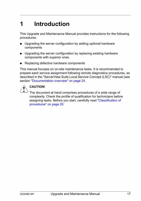
1 IntroductionThis Upgrade and Maintenance Manual provides instructions for the following procedures:
● Upgrading the server configuration by adding optional hardware components
● Upgrading the server configuration by replacing existing hardware components with superior ones.
● Replacing defective hardware components
This manual focuses on on-site maintenance tasks. It is recommended to prepare each service assignment following remote diagnostics procedures, as described in the "ServerView Suite Local Service Concept (LSC)" manual (see section "Documentation overview" on page 24.
V CAUTION!
The document at hand comprises procedures of a wide range of complexity. Check the profile of qualification for technicians before assigning tasks. Before you start, carefully read "Classification of procedures" on page 20.
18 Upgrade and Maintenance Manual GX2460 M1
Introduction
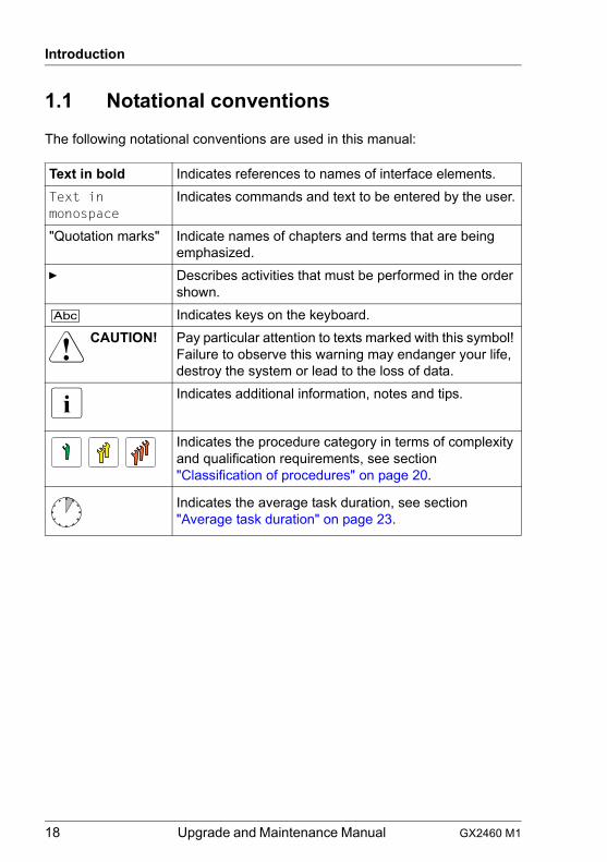
1.1 Notational conventions
The following notational conventions are used in this manual:
Text in bold Indicates references to names of interface elements.Text in monospace
Indicates commands and text to be entered by the user.
"Quotation marks" Indicate names of chapters and terms that are being emphasized.
Ê Describes activities that must be performed in the order shown.
[Abc] Indicates keys on the keyboard.V CAUTION! Pay particular attention to texts marked with this symbol!
Failure to observe this warning may endanger your life, destroy the system or lead to the loss of data.
I Indicates additional information, notes and tips.
Indicates the procedure category in terms of complexity and qualification requirements, see section "Classification of procedures" on page 20.
Indicates the average task duration, see section "Average task duration" on page 23.
GX2460 M1 Upgrade and Maintenance Manual 19
2 Before you startBefore you start any upgrade or maintenance task, proceed as follows:
Ê Carefully read the safety instructions in chapter "Important information" on page 27.
Ê Make sure that all necessary manuals are available, see the documentation overview in section "Documentation overview" on page 24. Print the PDF files if required.
Ê Make yourself familiar with the procedure categories introduced in section "Classification of procedures" on page 20.
Ê Ensure that all required tools are available according to section "Tools you need at hand" on page 24.
Installing optional components
The operating manual of your server gives an introduction to server features and provides an overview of available hardware options.
I For the latest information on hardware options, see the hardware configurator of your server, available online at the following address:http://ts.fujitsu.com/products/standard_servers/index.htm
For Japan:http://www.fujitsu.com/jp/products/computing/servers/primergy/
Please contact your local Fujitsu customer service partner for details on how to order expansion kits or spare parts. Use the Fujitsu Illustrated Spares Catalog to identify the required spare part and obtain technical data and order information. Illustrated Spares catalogs are available online at http://manuals.ts.fujitsu.com/illustrated_spares (not valid for Japan).
Replacing a defective component
The System Status indicator on the front of the server reports defective hardware components that need to be replaced. For more information on the controls and indicators of your server, see the operating manual of your server and section "Connectors and indicators" on page 222.
20 Upgrade and Maintenance Manual GX2460 M1
Before you start
2.1 Classification of procedures
The complexity of maintenance procedures varies significantly. Procedures have been assigned to one of three unit categories, indicating the level of difficulty and required qualification.At the beginning of each procedure, the involved unit type is indicated by one of the symbols introduced in this section.
I Please ask your local Fujitsu service center for more information.
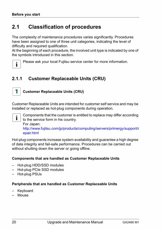
2.1.1 Customer Replaceable Units (CRU)
Customer Replaceable Units are intended for customer self service and may be installed or replaced as hot-plug components during operation.
I Components that the customer is entitled to replace may differ according to the service form in his country.For Japan:http://www.fujitsu.com/jp/products/computing/servers/primergy/support/repair.html
Hot-plug components increase system availability and guarantee a high degree of data integrity and fail-safe performance. Procedures can be carried out without shutting down the server or going offline.
Components that are handled as Customer Replaceable Units
– Hot-plug HDD/SSD modules– Hot-plug PCIe SSD modules– Hot-plug PSUs
Peripherals that are handled as Customer Replaceable Units
– Keyboard– Mouse
Customer Replaceable Units (CRU)
GX2460 M1 Upgrade and Maintenance Manual 21
Before you start
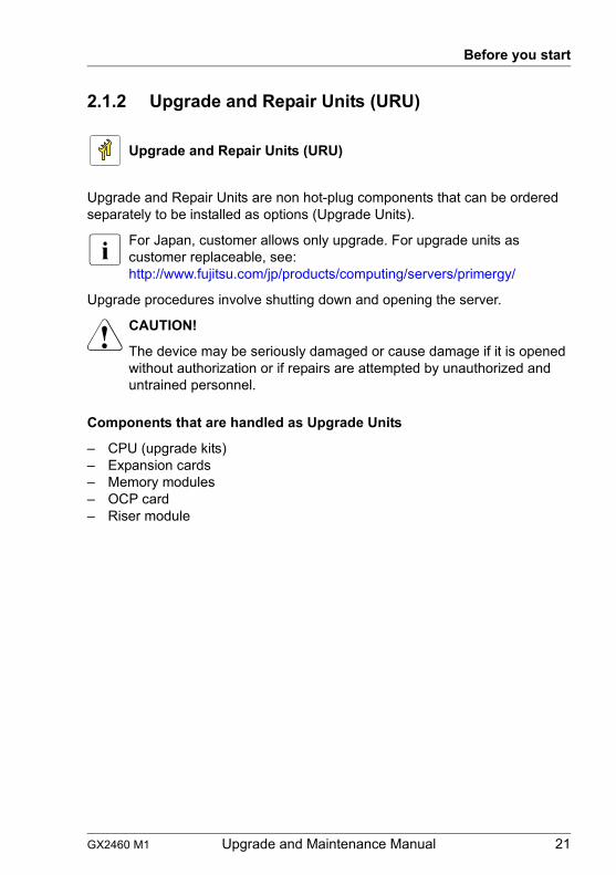
2.1.2 Upgrade and Repair Units (URU)
Upgrade and Repair Units are non hot-plug components that can be ordered separately to be installed as options (Upgrade Units).
I For Japan, customer allows only upgrade. For upgrade units as customer replaceable, see:http://www.fujitsu.com/jp/products/computing/servers/primergy/
Upgrade procedures involve shutting down and opening the server.
V CAUTION!
The device may be seriously damaged or cause damage if it is opened without authorization or if repairs are attempted by unauthorized and untrained personnel.
Components that are handled as Upgrade Units
– CPU (upgrade kits)– Expansion cards– Memory modules– OCP card– Riser module
Upgrade and Repair Units (URU)
22 Upgrade and Maintenance Manual GX2460 M1
Before you start
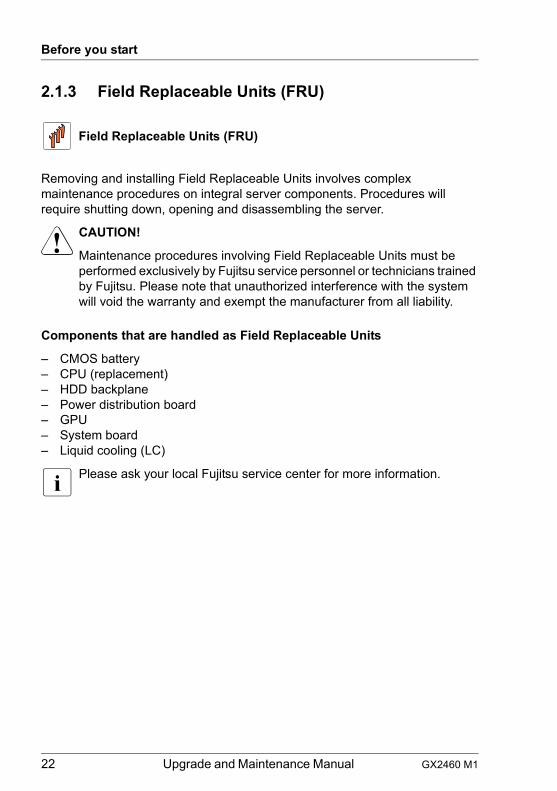
2.1.3 Field Replaceable Units (FRU)
Removing and installing Field Replaceable Units involves complex maintenance procedures on integral server components. Procedures will require shutting down, opening and disassembling the server.
V CAUTION!
Maintenance procedures involving Field Replaceable Units must be performed exclusively by Fujitsu service personnel or technicians trained by Fujitsu. Please note that unauthorized interference with the system will void the warranty and exempt the manufacturer from all liability.
Components that are handled as Field Replaceable Units
– CMOS battery– CPU (replacement)– HDD backplane– Power distribution board– GPU– System board– Liquid cooling (LC)
I Please ask your local Fujitsu service center for more information.
Field Replaceable Units (FRU)
GX2460 M1 Upgrade and Maintenance Manual 23
Before you start
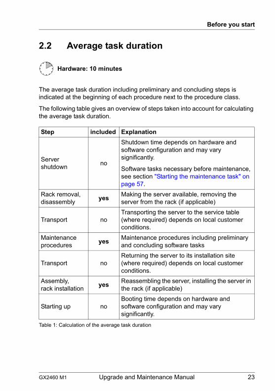
2.2 Average task duration
The average task duration including preliminary and concluding steps is indicated at the beginning of each procedure next to the procedure class.
The following table gives an overview of steps taken into account for calculating the average task duration.
Hardware: 10 minutes
Step included Explanation
Server shutdown no
Shutdown time depends on hardware and software configuration and may vary significantly.
Software tasks necessary before maintenance, see section "Starting the maintenance task" on page 57.
Rack removal, disassembly yes Making the server available, removing the
server from the rack (if applicable)
Transport noTransporting the server to the service table (where required) depends on local customer conditions.
Maintenance procedures yes Maintenance procedures including preliminary
and concluding software tasks
Transport noReturning the server to its installation site (where required) depends on local customer conditions.
Assembly, rack installation yes Reassembling the server, installing the server in
the rack (if applicable)
Starting up noBooting time depends on hardware and software configuration and may vary significantly.
Table 1: Calculation of the average task duration
24 Upgrade and Maintenance Manual GX2460 M1
Before you start
2.3 Tools you need at hand
When preparing the maintenance task, ensure that all required tools are available. You will find a list of required tools at the beginning of each procedure.
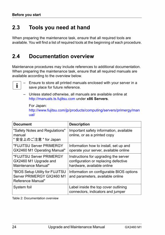
2.4 Documentation overview
Maintenance procedures may include references to additional documentation. When preparing the maintenance task, ensure that all required manuals are available according to the overview below.
I – Ensure to store all printed manuals enclosed with your server in a save place for future reference.
– Unless stated otherwise, all manuals are available online at http://manuals.ts.fujitsu.com under x86 Servers.
For Japan: http://www.fujitsu.com/jp/products/computing/servers/primergy/manual/
Document Description"Safety Notes and Regulations" manual" 安全上のご注意 " for Japan
Important safety information, available online, or as a printed copy
"FUJITSU Server PRIMERGY GX2460 M1 Operating Manual"
Information how to install, set up and operate your server, available online
"FUJITSU Server PRIMERGY GX2460 M1 Upgrade and Maintenance Manual"
Instructions for upgrading the server configuration or replacing defective hardware, available online
"BIOS Setup Utility for FUJITSU Server PRIMERGY GX2460 M1 Reference Manual"
Information on configurable BIOS options and parameters, available online
System foil Label inside the top cover outlining connectors, indicators and jumper
Table 2: Documentation overview
GX2460 M1 Upgrade and Maintenance Manual 25
Before you start
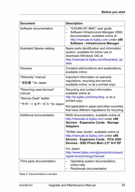
Software documentation – "GX2460 M1 BMC" user guide– Software Infrastructure Manager (ISM)
documentation, available online at http://manuals.ts.fujitsu.com under x86 Software - Infrastructure Manager
Illustrated Spares catalog Spare parts identification and information system, available for online use or download (Windows OS) at http://manuals.ts.fujitsu.com/illustrated_spares
Glossary Contains abbreviations and explanations, available online
"Warranty" manual
" 保証書 " for Japan
Important information on warranty regulations, recycling and service, available online, or as a printed copy
"Returning used devices" manual
Recycling and contact information, available online at http://ts.fujitsu.com/recycling, or as a printed copy
Not applicable in Japan and other countries that have different regulations for recycling
"Service Desk" leaflet
"サポート&サービス " for Japan
Additional documentation RAID documentation, available online at http://manuals.ts.fujitsu.com under x86 Servers - Expansion Cards - Storage Adapters
"NVMe User Guide", available online at http://manuals.ts.fujitsu.com under x86 Servers - Expansion Cards - PCIe SSD Devices - SSD PCie3 Main 2.5" H-P EP
For Japan: http://www.fujitsu.com/jp/products/computing/servers/primergy/manual/
Third party documentation – Operating system documentation, online help
– Peripherals documentation
Document Description
Table 2: Documentation overview

26 Upgrade and Maintenance Manual GX2460 M1
Before you start
GX2460 M1 Upgrade and Maintenance Manual 27
3 Important informationI Depending on your server or the installed options some information is not
valid for your server.
V CAUTION!
Before installing and starting up a server, please observe the safety instructions listed in the following section. This will help you to avoid making serious errors that could impair your health, damage the server and endanger the data base.
3.1 Safety instructions
I The following safety instructions are also provided in the manual "Safety Notes and Regulations" or " 安全上のご注意 ".
This server meets the relevant safety regulations for IT equipment. If you have any questions about whether you can install the server in the intended environment, please contact your sales outlet or our customer service team.
● The actions described in this manual shall be performed by technical specialists. A technical specialist is a person who is trained to install the server including hardware and software.
● Repairs to the server that do not relate to CSS failures shall be performed by service personnel. Please note that unauthorized interference with the server will void the warranty and exempt the manufacturer from all liability.
● Any failure to observe the guidelines in this manual, and any improper repairs could expose the user to risks (electric shock, energy hazards, fire hazards) or damage the equipment.
● Only valid for non hot-plug componentsBefore installing/removing internal components to/from the server, turn off the server, all peripheral devices, and any other connected devices. Also unplug all power cords from the power outlet. Failure to do so can cause electric shock or damage.
Before starting up
● During installation and before operating the server, observe the instructions on environmental conditions for your server.
28 Upgrade and Maintenance Manual GX2460 M1
Important information
● If the server is brought in from a cold environment, condensation may form both inside and on the outside of the server.
Wait until the server has acclimatized to room temperature and is absolutely dry before starting it up. Material damage may be caused to the server if this requirement is not observed.
● Only transport the server in its original packaging or in packaging that protects it from impacts and jolts.In Japan and APAC, transporting the server in its original packaging does not apply.
Installation and operation
● This server should not be operated in ambient temperatures above 35 °C. For servers with Advanced Thermal Design the ambient temperature can increase to 40 °C or 45 °C.
● If the server is integrated into an installation that draws power from an industrial power supply network with an IEC309 connector, the power supply's fuse protection must comply with the requirements for non-industrial power supply networks for type A connectors.
● The server automatically adjusts itself to a mains voltage, see the type label of your server. Ensure that the local mains voltage lies within these limits.
● This server must only be connected to properly grounded power outlets or connected to the grounded rack internal power distribution server with tested and approved power cords.
● Ensure that the server is connected to a properly grounded power outlet close to the server.
● Ensure that the power sockets on the server and the properly grounded power outlets are easily accessible.
● The On/Off button or the main power switch (if present) does not isolate the server from the mains power supply. In case of repair or servicing disconnect the server completely from the mains power supply, unplug all power plugs from the properly grounded power outlets.
● Always connect the server and the attached peripheral devices to the same power circuit. Otherwise you run the risk of losing data if, for example, the server is still running but a peripheral device (e.g. memory subsystem) fails during a power outage.
● The adequately shielded data cables must be used.
GX2460 M1 Upgrade and Maintenance Manual 29
Important information
All data and signal cables must have sufficient shielding. The use of cable type S/FTP Cat5 or higher is recommended. Use of unshielded or badly shielded cables may lead to increased emission of interference and/or reduced fault-tolerance of the device.
● Ethernet cabling has to comply with EN 50173 and EN 50174-1/2 standards or ISO/IEC 11801 standard respectively. The minimum requirement is a Category 5 shielded cable for 10/100 Ethernet, or a Category 5e cable for Gigabit Ethernet.
● Route the cables in such a way that they do not create a potential hazard (ensure that no-one can trip over them) and that they cannot be damaged. When connecting the server, see the relevant instructions in this manual.
● Never connect or disconnect data transmission lines during a storm (risk of lightning hazard).
● Ensure that no objects (e.g. jewelry, paperclips etc.) or liquids can get inside the server (risk of electric shock, short circuit).
● In emergencies (e.g. damaged casing, controls or cables, penetration of liquids or foreign bodies), contact the server administrator or your customer service team. Only disconnect the server from the mains power supply if there is no risk of harming yourself.
● Proper operation of the server (in accordance with IEC 60950-1 resp. EN 60950-1) is only ensured if the server is completely assembled and the rear covers for the installation slots have been fitted (electric shock, cooling, fire protection, interference suppression).
● Only install server expansions that satisfy the requirements and rules governing safety and electromagnetic compatibility and those relating to telecommunication terminals. If you install other expansions, they may damage the server or violate the safety regulations. Information on which server expansions are approved for installation can be obtained from our customer service center or your sales outlet.
● The components marked with a warning notice (e.g. lightning symbol) may only be opened, removed or exchanged by authorized, qualified personnel. Exception: CSS components can be replaced.
● The warranty is void if the server is damaged during installation or replacement of server expansions.
● Only set screen resolutions and refresh rates that are specified in the operating manual for the monitor. Otherwise, you may damage your monitor. If you are in any doubt, contact your sales outlet or customer service center.
30 Upgrade and Maintenance Manual GX2460 M1
Important information
● Only valid for non hot-plug componentsBefore installing/removing internal components to/from the server, turn off the server, all peripheral devices, and any other connected devices. Also unplug all power cords from the power outlet. Failure to do so can cause electric shock or damage.
Internal devices remain hot after shutdown. Wait for a while after shutdown before installing or removing internal options.
● Do not damage or modify internal cables or internal devices. Doing so may cause a server failure, fire, or electric shock and will void the warranty and exempt the manufacturer from all liability.
● The circuit boards and soldered parts of internal options are exposed and can be damaged by static electricity. To ensure reliable protection, you must wear an earthing band on your wrist when working with this type of module and connect it to an unpainted, conducting metal part of the server.
● Do not touch the circuitry on boards or soldered parts. Hold the metallic areas or the edges of the circuit boards.
● Install the screw removed during installation/detaching internal options in former position. To use a screw of the different kind can cause a breakdown of equipment.
● The procedure of installation on this notes might change depending on a configuration of option.
Batteries
● Incorrect replacement of batteries may lead to a risk of explosion. The batteries may only be replaced with identical batteries or with a type recommended by the manufacturer.
● Do not throw batteries into the trash can.
Batteries must be disposed of in accordance with local regulations concerning special waste.
● Ensure that you insert the battery the right way round.
● The battery used in this server may present a fire or chemical burn hazard if mistreated. Do not disassemble, heat about 100 °C (212F), or incinerate the battery.
GX2460 M1 Upgrade and Maintenance Manual 31
Important information
● Replace the lithium battery on the system board in accordance with the instructions in the corresponding Upgrade and Maintenance Manual, chapter "System board and components" > "CMOS battery".
● All batteries containing pollutants are marked with a symbol (a crossed-out garbage can). In addition, the marking is provided with the chemical symbol of the heavy metal decisive for the classification as a pollutant:
Cd Cadmium Hg Mercury Pb Lead
Working with optical disk drives (ODDs) and media
When working with ODDs, these instructions must be followed.
V CAUTION!
● Only use CDs/DVDs/BDs that are in perfect condition, in order to prevent data loss, equipment damage and injury.
● Check each CD/DVD/BD for damage, cracks, breakages etc. before inserting it in the drive.
Note that any additional labels applied may change the mechanical properties of a CD/DVD/BD and cause imbalance and vibrations.
Damaged and imbalanced CDs/DVDs/BDs can break at high drive speeds (data loss).
Under certain circumstances, sharp CD/DVD/BD fragments can pierce the cover of the ODD (equipment damage) and can fly out of the drive (danger of injury, particularly to uncovered body parts such as the face or neck).
● High humidity and airborne dust levels are to be avoided. Electric shocks and/or server failures may be caused by liquids such as water, or metallic items, such as paper clips, entering a drive.
● Shocks and vibrations are also to be avoided.
● Do not insert any objects other than the specified CDs/DVDs/BDs.
● Do not pull on, press hard, or otherwise handle the CD/DVD/BD tray roughly.
● Do not disassemble the ODD.
● Before use, clean the ODD tray using a soft, dry cloth.
32 Upgrade and Maintenance Manual GX2460 M1
Important information
● As a precaution, remove disks from the ODD when the drive is not to be used for a long time. Keep the ODD tray closed to prevent foreign matter, such as dust, from entering the ODD.
● Hold CDs/DVDs/BDs by their edges to avoid contact with the disk surface.
● Do not contaminate the CD/DVD/BD surface with fingerprints, oil, dust, etc. If dirty, clean with a soft, dry cloth, wiping from the center to the edge. Do not use benzene, thinners, water, record sprays, antistatic agents, or silicone-impregnated cloth.
● Be careful not to damage the CD/DVD/BD surface.
● Keep the CDs/DVDs/BDs away from heat sources.
● Do not bend or place heavy objects on CDs/DVDs/BDs.
● Do not write with ballpoint pen or pencil on the label (printed) side.
● Do not attach stickers or similar to the label side. Doing so may cause rotational eccentricity and abnormal vibrations.
● When a CD/DVD/BD is moved from a cold place to a warm place, moisture condensation on the CD/DVD/BD surface can cause data read errors. In this case, wipe the CD/DVD/BD with a soft, dry cloth then let it air dry. Do not dry the CD/DVD/BD using devices such as a hair dryer.
● To avoid dust, damage, and deformation, keep the CD/DVD/BD in its case whenever it is not in use.
● Do not store CDs/DVDs/BDs at high temperatures. Areas exposed to prolonged direct sunlight or near heating appliances are to be avoided.
I You can prevent damage from the ODD and the CDs/DVDs/BDs, as well as premature wear of the disks, by observing the following suggestions:
– Only insert disks in the drive when needed and remove them after use.
– Store the disks in suitable sleeves.– Protect the disks from exposure to heat and direct sunlight.
GX2460 M1 Upgrade and Maintenance Manual 33
Important information
Laser information
The ODD complies with IEC 60825-1 laser class 1.
V CAUTION!
The ODD contains a light-emitting diode (LED), which under certain circumstances produces a laser beam stronger than laser class 1. Looking directly at this beam is dangerous.
Never remove parts of the ODD casing!
Modules with Electrostatic-Sensitive Devices (ESD modules)
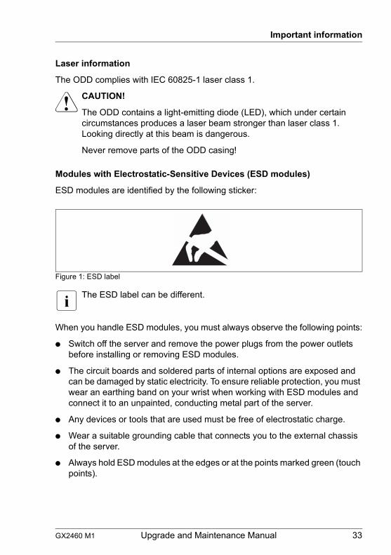
ESD modules are identified by the following sticker:
Figure 1: ESD label
I The ESD label can be different.
When you handle ESD modules, you must always observe the following points:
● Switch off the server and remove the power plugs from the power outlets before installing or removing ESD modules.
● The circuit boards and soldered parts of internal options are exposed and can be damaged by static electricity. To ensure reliable protection, you must wear an earthing band on your wrist when working with ESD modules and connect it to an unpainted, conducting metal part of the server.
● Any devices or tools that are used must be free of electrostatic charge.
● Wear a suitable grounding cable that connects you to the external chassis of the server.
● Always hold ESD modules at the edges or at the points marked green (touch points).
34 Upgrade and Maintenance Manual GX2460 M1
Important information
● Do not touch any connectors or conduction paths on an ESD module.
● Place all the components on a pad which is free of electrostatic charge.
I For a detailed description of how to handle ESD modules, see the relevant European or international standards (EN 61340-5-1, ANSI/ESD S20.20).
Transporting the server
V CAUTION!
Only transport the server in its original packaging or in packaging that protects it from impacts and jolts.In Japan and APAC, transporting the server in its original packaging does not apply.
Do not unpack the server until it is at its installation location.
If you need to lift or transport the server, ask other people to help you.
Never lift or carry the server by the handles or the Quick Release Levers (QRLs) on the front panel.
Notes on installing the server in the rack
V CAUTION!
● For safety reasons, at least 2 people are required to install the server in the rack because of its weight and size.
(For Japan, see " 安全上のご注意 ".)
● Never lift the server into the rack using the QRLs on the front panel.
● When connecting and disconnecting cables, observe the relevant instructions in the "Important Information" chapter of the technical manual for the corresponding rack. The technical manual is supplied with the corresponding rack.
● When installing the rack, ensure that the anti-tilt mechanism is correctly fitted.
● Do not extend more than one server out of the rack simultaneously even if the tilt protection is in place. If several servers are simultaneously extended from the rack, there is a risk that the rack could tip over. See the safety information of the rack and the warning label.
GX2460 M1 Upgrade and Maintenance Manual 35
Important information
● If the server/rack is intended for permanent connection to the mains only an authorized specialist (electrician) is allowed to work.Please follow the regulation of each country.
● If the server is integrated into an installation that draws power from an industrial power supply network with an IEC309 type connector, the power supply's fuse protection must comply with the requirements for non-industrial power supply networks for the type A connector.
Other important information
● During cleaning, observe the instructions in the corresponding Operating Manual chapter "Starting up and operation" > "Cleaning the server".
● Keep all manuals close to the server. All documentation must be included if the equipment is passed on to a third party.
3.2 CE conformity
The system complies with the requirements of European Regulations. Find the CE declaration on certificate portal:https://sp.ts.fujitsu.com/sites/certificates/default.aspx
To open the CE declaration applicable for your system, proceed as follows:
Ê Select Industry Standard Servers.
Ê Select your model, e.g. Rack server.
Ê Select your system, e.g. PRIMERGY RX2530 M1.
Ê Select CE Cert <your system>.
V CAUTION!
This is a Class A product. In a domestic environment this product may cause RF interference, in which case the user may be required to take adequate measures.
36 Upgrade and Maintenance Manual GX2460 M1
Important information
3.3 FCC Class A Compliance Statement
If there is an FCC statement on the device, it applies to the products covered in this manual, unless otherwise specified herein. The statement for other products will appear in the accompanying documentation.
NOTE:
This equipment has been tested and found to comply with the limits for a "Class A" digital device, pursuant to Part 15 of the FCC rules and meets all requirements of the Canadian Interference-Causing Equipment Standard ICES-003 for digital apparatus. These limits are designed to provide reasonable protection against harmful interference in a residential installation. This equipment generates, uses and can radiate radio frequency energy and, if not installed and used in strict accordance with the instructions, may cause harmful interference to radio communications. However, there is no warranty that interference will not occur in a particular installation. If this equipment does cause harmful interference to radio or television reception, which can be determined by turning the equipment off and on, the user is encouraged to try to correct the interference by one or more of the following measures:
● Reorient or relocate the receiving antenna.
● Increase the separation between equipment and the receiver.
● Connect the equipment into an outlet on a circuit different from that to which the receiver is connected.
● Consult the dealer or an experienced radio/TV technician for help.
Fujitsu is not responsible for any radio or television interference caused by unauthorized modifications of this equipment or the substitution or attachment of connecting cables and equipment other than those specified by Fujitsu. The correction of interferences caused by such unauthorized modification, substitution or attachment will be the responsibility of the user.
The use of shielded I/O cables is required when connecting this equipment to any and all optional peripheral or host devices. Failure to do so may violate FCC and ICES rules.

GX2460 M1 Upgrade and Maintenance Manual 37
Important information
3.4 Environmental protection
Environmentally-friendly product design and development
This product has been designed in accordance with the Fujitsu standard for "environmentally friendly product design and development". This means that key factors such as durability, selection and labeling of materials, emissions, packaging, ease of dismantling and recycling have been taken into account.This saves resources and thus reduces the harm done to the environment. More information can be found at:http://ts.fujitsu.com/products/standard_servers/index.html
For Japan:http://jp.fujitsu.com/platform/server/primergy/concept/
Energy-saving information
Devices that do not need to be constantly switched on should be switched off until they are needed as well as during long breaks and after completion of work.
Packaging information
This packaging information does not apply in Japan and APAC.Do not throw away the packaging. You may need it later for transporting the server. If possible, the equipment should only be transported in its original packaging.
Information on handling consumables
Please dispose of printer consumables and batteries in accordance with the applicable national regulations.
In accordance with EU directives, batteries must not be disposed of with unsorted domestic waste. They can be returned free of charge to the manufacturer, dealer or an authorized agent for recycling or disposal.
All batteries containing pollutants are marked with a symbol (a crossed-out garbage can). They are also marked with the chemical symbol for the heavy metal that causes them to be categorized as containing pollutants:
Cd CadmiumHg MercuryPb Lead
38 Upgrade and Maintenance Manual GX2460 M1
Important information
Labels on plastic casing parts
Please avoid sticking your own labels on plastic parts wherever possible, since this makes it difficult to recycle them.
Returns, recycling and disposal
Please handle returns, recycling and disposal in accordance with local regulations.
Details regarding the return and recycling of devices and consumables within Europe can also be found in the "Returning used devices" manual, via your local Fujitsu branch, or at:http://ts.fujitsu.com/recycling
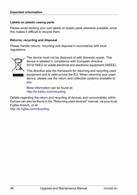
The device must not be disposed of with domestic waste. This device is labeled in compliance with European directive 2012/19/EU on waste electrical and electronic equipment (WEEE).
This directive sets the framework for returning and recycling used equipment and is valid across the EU. When returning your used device, please use the return and collection systems available to you.
More information can be found at:http://ts.fujitsu.com/recycling
GX2460 M1 Upgrade and Maintenance Manual 39
4 Basic hardware procedures
4.1 Using diagnostics information
I In Japan remote diagnostics procedures are not used.
Please contact your local Fujitsu customer service partner for details on the service concept and on how to order expansion kits or spare parts.
4.1.1 Locating the defective server
For easy identification of the server, switch on the ID indicator, especially when working in a datacenter environment or a server room.
Ê Press the ID button on the front panel board.
Ê Remember to switch off the ID indicator after the maintenance task has been concluded successfully.
4.1.2 Locating the defective component
● Check the System Event Log (SEL), see section "Viewing the SEL" on page 60.
● Check the indicators on the components, see section "Connectors and indicators" on page 222.
● Check the onboard indicators on the system board.
40 Upgrade and Maintenance Manual GX2460 M1
Basic hardware procedures
4.2 Shutting down the server
V CAUTION!
For more information, see chapter "Important information" on page 27.
I This step is only required when upgrading or replacing non-hot plug components.
Ê Inform the system administrator that the server will be shut down and put offline.
Ê Terminate all applications.
Ê Perform the required procedures described in the preliminary steps of each upgrade or maintenance task.
Ê Shut down the server.
I If the system is running an ACPI-compliant operating system, pressing the On/Off button will perform a graceful shutdown.
Ê Switch on the ID indicator on the front panel and I/O panel of the server, see section "Locating the defective server" on page 39.
GX2460 M1 Upgrade and Maintenance Manual 41
Basic hardware procedures
4.3 Disconnecting the power cord
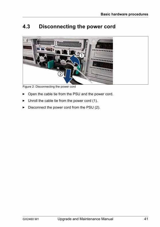
Figure 2: Disconnecting the power cord
Ê Open the cable tie from the PSU and the power cord.
Ê Unroll the cable tie from the power cord (1).
Ê Disconnect the power cord from the PSU (2).
42 Upgrade and Maintenance Manual GX2460 M1
Basic hardware procedures
4.4 Getting access to the component
V CAUTION!
● Only for non-hot plug components:Before removing or attaching covers, turn off the server, all peripheral devices, and any other connected devices. Because there is a risk of electric shock or damage, please disconnect all power cords from the outlet.
● The housing covers must be replaced as soon as possible for purposes of cooling, to comply with EMC regulations (regulations regarding electromagnetic compatibility) and to prevent fires.
● For more information, see chapter "Important information" on page 27.
4.4.1 Extending the server out of the rack
V CAUTION!
● Use the anti-tilt plate to prevent the rack from tipping when installing the rack. Pulling the server out of the rack without having installed the anti-tilt plate may cause the rack to tip over.
● Be careful not to pinch fingers or clothes when sliding out the server or pushing it back. Failure to do so may cause injury.
● For more information, see chapter "Important information" on page 27.
Ê Remove all remaining external cables and earthing cable from the I/O panel and expansion cards.
GX2460 M1 Upgrade and Maintenance Manual 43
Basic hardware procedures
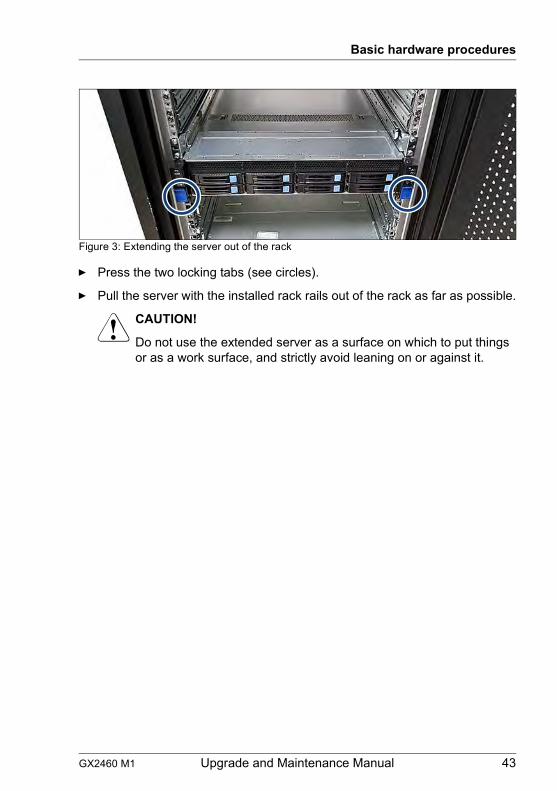
Figure 3: Extending the server out of the rack
Ê Press the two locking tabs (see circles).
Ê Pull the server with the installed rack rails out of the rack as far as possible.
V CAUTION!
Do not use the extended server as a surface on which to put things or as a work surface, and strictly avoid leaning on or against it.
44 Upgrade and Maintenance Manual GX2460 M1
Basic hardware procedures
4.4.2 Removing the server from the rack
I In most cases maintenance tasks can be performed while the server is extended from the rack. However, depending on accessibility or security guidelines, it may make sense to completely remove the server from the rack cabinet for maintenance purposes.
V CAUTION!
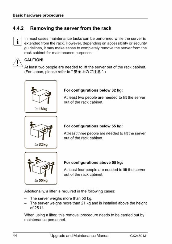
At least two people are needed to lift the server out of the rack cabinet.(For Japan, please refer to " 安全上のご注意 ".)
Additionally, a lifter is required in the following cases:
– The server weighs more than 50 kg.– The server weighs more than 21 kg and is installed above the height
of 25 U.
When using a lifter, this removal procedure needs to be carried out by maintenance personnel.
For configurations below 32 kg:
At least two people are needed to lift the server out of the rack cabinet.
For configurations below 55 kg:
At least three people are needed to lift the server out of the rack cabinet.
For configurations above 55 kg:
At least four people are needed to lift the server out of the rack cabinet.

GX2460 M1 Upgrade and Maintenance Manual 45
Basic hardware procedures
Figure 4: Pressing the latch key
Ê Press the latch key to pull out the server (1).
Ê Pull the server in the direction of the arrow (2).
Ê Lift the server out of the rack and place it on an even surface.
46 Upgrade and Maintenance Manual GX2460 M1
Basic hardware procedures
4.5 Removing the top covers
4.5.1 Removing the front top cover
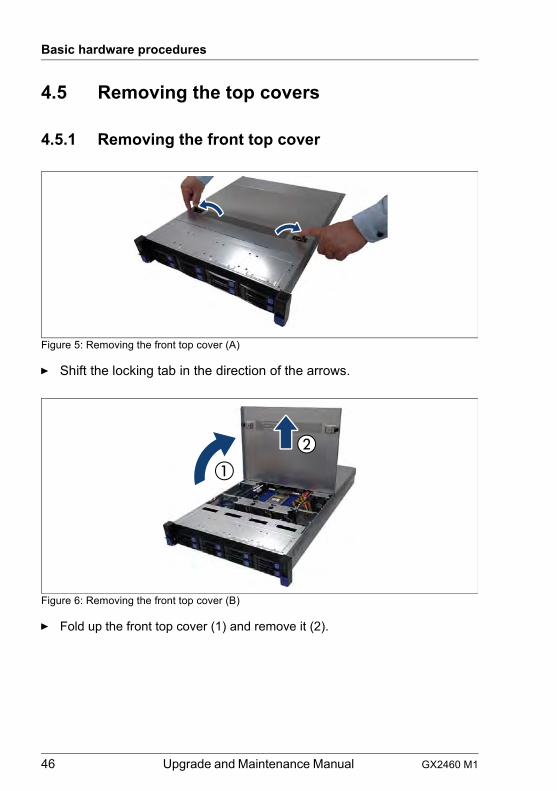
Figure 5: Removing the front top cover (A)
Ê Shift the locking tab in the direction of the arrows.
Figure 6: Removing the front top cover (B)
Ê Fold up the front top cover (1) and remove it (2).
GX2460 M1 Upgrade and Maintenance Manual 47
Basic hardware procedures
4.5.2 Removing the rear top cover
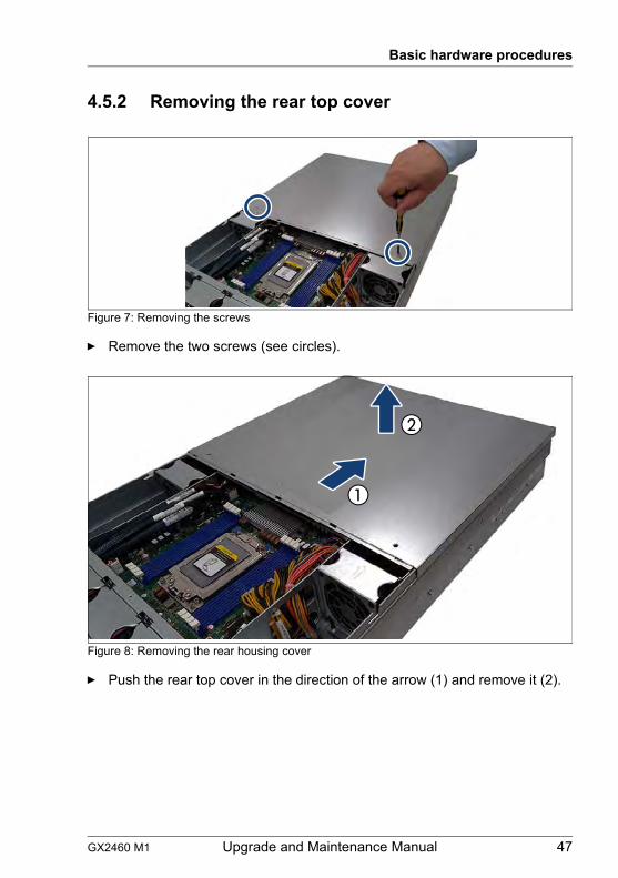
Figure 7: Removing the screws
Ê Remove the two screws (see circles).
Figure 8: Removing the rear housing cover
Ê Push the rear top cover in the direction of the arrow (1) and remove it (2).
48 Upgrade and Maintenance Manual GX2460 M1
Basic hardware procedures
4.6 Installing the top covers
4.6.1 Installing the rear top cover
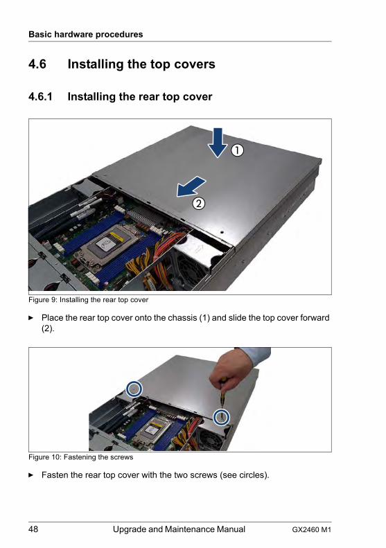
Figure 9: Installing the rear top cover
Ê Place the rear top cover onto the chassis (1) and slide the top cover forward (2).
Figure 10: Fastening the screws
Ê Fasten the rear top cover with the two screws (see circles).
GX2460 M1 Upgrade and Maintenance Manual 49
Basic hardware procedures
4.6.2 Installing the front top cover
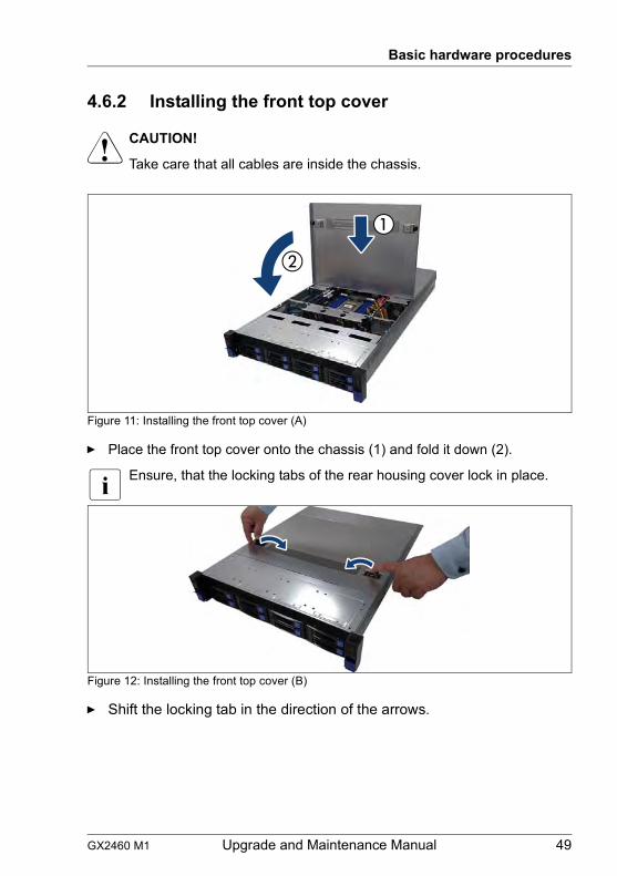
V CAUTION!
Take care that all cables are inside the chassis.
Figure 11: Installing the front top cover (A)
Ê Place the front top cover onto the chassis (1) and fold it down (2).
I Ensure, that the locking tabs of the rear housing cover lock in place.
Figure 12: Installing the front top cover (B)
Ê Shift the locking tab in the direction of the arrows.
50 Upgrade and Maintenance Manual GX2460 M1
Basic hardware procedures
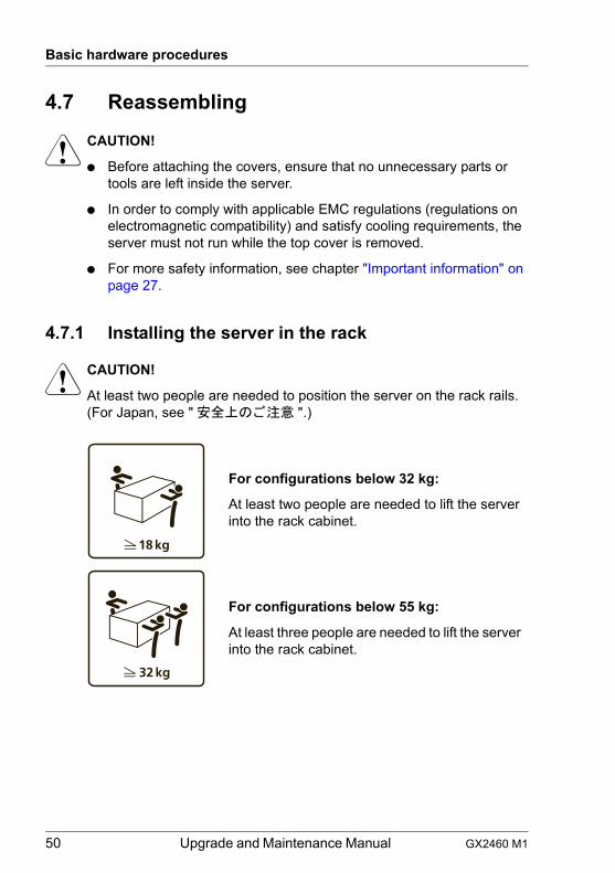
4.7 Reassembling
V CAUTION!
● Before attaching the covers, ensure that no unnecessary parts or tools are left inside the server.
● In order to comply with applicable EMC regulations (regulations on electromagnetic compatibility) and satisfy cooling requirements, the server must not run while the top cover is removed.
● For more safety information, see chapter "Important information" on page 27.
4.7.1 Installing the server in the rack
V CAUTION!
At least two people are needed to position the server on the rack rails. (For Japan, see " 安全上のご注意 ".)
For configurations below 32 kg:
At least two people are needed to lift the server into the rack cabinet.
For configurations below 55 kg:
At least three people are needed to lift the server into the rack cabinet.
GX2460 M1 Upgrade and Maintenance Manual 51
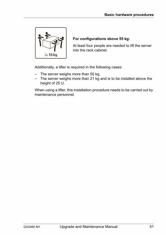
Basic hardware procedures
Additionally, a lifter is required in the following cases:
– The server weighs more than 50 kg.– The server weighs more than 21 kg and is to be installed above the
height of 25 U.
When using a lifter, this installation procedure needs to be carried out by maintenance personnel.
For configurations above 55 kg:
At least four people are needed to lift the server into the rack cabinet.
52 Upgrade and Maintenance Manual GX2460 M1
Basic hardware procedures
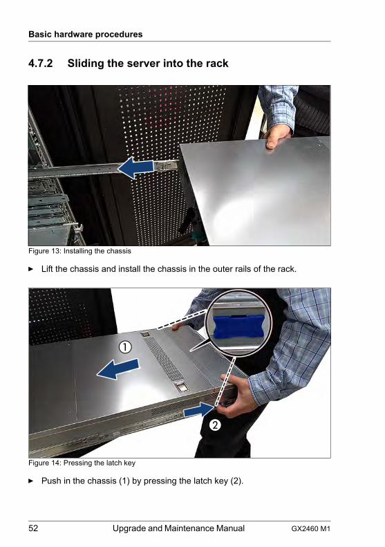
4.7.2 Sliding the server into the rack
Figure 13: Installing the chassis
Ê Lift the chassis and install the chassis in the outer rails of the rack.
Figure 14: Pressing the latch key
Ê Push in the chassis (1) by pressing the latch key (2).
GX2460 M1 Upgrade and Maintenance Manual 53
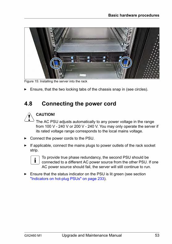
Basic hardware procedures
Figure 15: Installing the server into the rack
Ê Ensure, that the two locking tabs of the chassis snap in (see circles).
4.8 Connecting the power cord
V CAUTION!
The AC PSU adjusts automatically to any power voltage in the range from 100 V - 240 V or 200 V - 240 V. You may only operate the server if its rated voltage range corresponds to the local mains voltage.
Ê Connect the power cords to the PSU.
Ê If applicable, connect the mains plugs to power outlets of the rack socket strip.
I To provide true phase redundancy, the second PSU should be connected to a different AC power source from the other PSU. If one AC power source should fail, the server will still continue to run.
Ê Ensure that the status indicator on the PSU is lit green (see section "Indicators on hot-plug PSUs" on page 233).

54 Upgrade and Maintenance Manual GX2460 M1
Basic hardware procedures
Figure 16: Connecting the power cord
Ê Connect the power cord to the PSU (1).
Ê If applicable, connect the mains plug to a grounded mains outlet in the inhouse power supply network.
Ê Roll the cable tie around the power cord and the handle of the PSU (2).
Ê Fix the cable tie.
I It will take about 60 seconds until the server can be powered on.
4.9 Switching on the server
V CAUTION!
● Before switching on the server, ensure that the top cover is closed. In order to comply with applicable EMC regulations (regulations on electromagnetic compatibility) and satisfy cooling requirements, the server must not run while the top cover is removed.
● For more safety information, see chapter "Important information" on page 27.
Ê Press the On/Off button to start up the server.
Ê Ensure that the power-on indicator is lit green.
GX2460 M1 Upgrade and Maintenance Manual 55
Basic hardware procedures
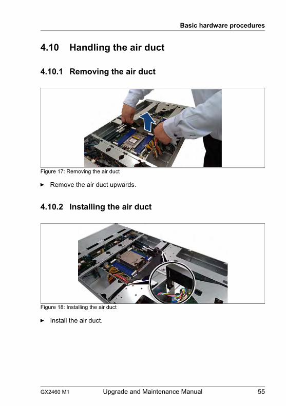
4.10 Handling the air duct
4.10.1 Removing the air duct
Figure 17: Removing the air duct
Ê Remove the air duct upwards.
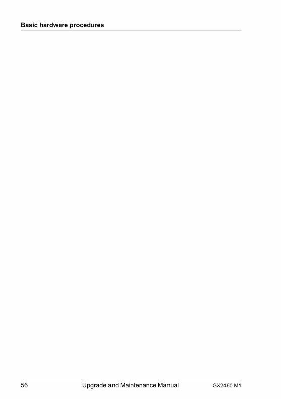
4.10.2 Installing the air duct
Figure 18: Installing the air duct
Ê Install the air duct.
56 Upgrade and Maintenance Manual GX2460 M1
Basic hardware procedures
GX2460 M1 Upgrade and Maintenance Manual 57
5 Basic software proceduresI Depending on your server and the installed features some information is
not valid for your server.
I Depending on your server and the installed features some information is not valid for your server.
5.1 Starting the maintenance task
5.1.1 Backing up the setting information of BIOS/BMC
Record or backup the important system configuring data, so that the settings other different to the standard settings of BIOS/BMC will not be lost when the service personnel replaces the system board.
5.1.2 Verifying and configuring the backup software solution
I This task only applies to Japan.
Depending on the backup software solution, it may be necessary to disable or delete the backup drive from the backup software drive list before starting the maintenance task.
I For more information on suitable backup software solutions and related documentation, see the Fujitsu web pages.
5.1.3 Switching on the ID indicator
For easy identification of the server, switch on the ID indicator, especially when working in a datacenter environment or a server room.
Ê Press the ID button on the front panel to switch on the system identification LEDs.
I For more information, see section "Server front" on page 227.
58 Upgrade and Maintenance Manual GX2460 M1
Basic software procedures
5.2 Completing the maintenance task
5.2.1 Updating or recovering the BIOS and BMC
I For Japan:Follow the instructions provided separately.
After replacing the system board, memory or a CPU, it is essential to upgrade the BIOS and BMC to the latest version. The latest BIOS and BMC versions are available from the Fujitsu support internet pages at:http://ts.fujitsu.com/support/
For Japan:http://www.fujitsu.com/jp/products/computing/servers/primergy/downloads/
I Fujitsu does not assume responsibility for any damage done to the server or for the loss of any data resulting from BIOS updates.
5.2.1.1 Updating the BIOS
BIOS flash procedure
Ê Perform the BIOS flash procedure as described in the readme file of the Flash Utilities provided by the Fujitsu service center.
5.2.1.2 Updating the BMC
BMC flash procedure
Perform the BMC flash update procedure as described in the "BMC User Guide" of your server.
5.2.2 Enabling Option ROM scan
In order to configure an expansion card that has been installed or replaced, the Option ROM of the card has to be enabled in the BIOS. The firmware of the card is called by the BIOS upon reboot and can be entered and configured.

GX2460 M1 Upgrade and Maintenance Manual 59
Basic software procedures
Option ROM can be enabled permanently (e.g. in case of a boot controller that may require frequent setup) or temporarily for one-time configuration. When permanently enabling a controllers’s Option ROM, keep in mind that only two Option ROMs can be activated in the BIOS at a time.
Ê Enter the BIOS.
Ê From the Advanced menu select Option ROM Configuration.
Ê Identify the desired PCI slot and set its Launch Slot # OpROM setting to Enabled.
Ê Save your changes and exit the BIOS.
I Up to two Option ROMs can be activated in the BIOS at a time.
For more information on how to access the BIOS and modify settings, see the corresponding BIOS Setup Utility reference manual.
When the enabled expansion card is initialized during the POST phase of the boot sequence, a key combination is displayed temporarily to enter the firmware of the expansion card.
Ê Press the displayed key combination.
Ê Modify the expansion card firmware options as desired.
Ê Save your changes and exit the firmware.
I The option ROM of the expansion card can now be disabled in the BIOS.
Exception: If the expansion card controls a permanent boot device, the Option ROM of the expansion card has to remain enabled.
5.2.3 Verifying the system time settings
After the system board has been replaced, the system time is set automatically. By default, the RTC (Real Time Clock) time standard is set as the local time.
If a Linux OS is used and the hardware clock has been configured as UTC (Universal Time, Coordinated) in the operating system, the BMC local time may not be mapped correctly.
Ê After replacing the system board, ask the system administrator whether the RTC or UTC time standard is to be used as system time.
I If the system time (RTC) is set to UTC, the SEL (System Event Log) time stamps may differ from the local time.
60 Upgrade and Maintenance Manual GX2460 M1
Basic software procedures
Ê Enter the BIOS.
Ê Select the Main menu.
Ê Under System Time and System Date specify the correct time and date.
I By default, the system time set in the BIOS is RTC (Real Time Clock) local time. If your IT infrastructure relies on universally accepted time standards, set the System Time to UTC (Universal Time, Coordinated) instead. Greenwich Mean Time (GMT) can be considered equivalent to UTC.
Ê Save your changes and exit the BIOS.
I For more information on how to access the BIOS and modify settings, see the corresponding BIOS Setup Utility reference manual.
5.2.4 Viewing and clearing the System Event Log (SEL)
5.2.4.1 Viewing the SEL
You can view the System Event Log (SEL) using the BMC web interface.
Ê Log in to the BMC web interface.
Ê Open the Logs & Reports menu.
Ê Click IPMI Event Log to open the System Event Log page.
Ê Under Event Log the SEL is displayed.
All events concerning the system are displayed in a table in the Event Log Content group.
I For more information on BMC settings, see the BMC user guide of your server.
5.2.4.2 Clearing the SEL
You can clear the System Event Log (SEL) using the BMC web interface.
Ê Log in to the BMC web interface.
Ê Open the Logs & Reports menu.
GX2460 M1 Upgrade and Maintenance Manual 61
Basic software procedures
Ê Click IPMI Event Log to open the System Event Log page.
Ê Click Clear Event Log to clear the SEL.
I For more information on BMC settings, see the BMC user guide of your server.
5.2.5 Updating the NIC configuration file in a Linux environment
In order to prevent errors caused by changing network device names (eth<x>), it is recommended to store the MAC address (hardware address) of a network interface card in the related NIC configuration file of the Linux OS.When replacing a network controller or the system board with onboard LAN controllers in a server running Linux OS, the MAC address will change but not automatically be updated in the definition file.
In order to prevent communication problems, it is necessary to update the changed MAC address stored in the related ifcfg-eth<x> definition file.
To update the MAC address, proceed as follows:
I Procedures may differ depending on your Linux OS or the definition file on the client system. Use the following information as reference. Ask the system administrator to change the definition file.
Ê After replacing a network controller or the system board, switch on and boot the server, see section "Switching on the server" on page 54.
The hardware configuration tool for Red Hat Linux, will launch at boot and detect the new and/or changed hardware on your system.
Ê For the changes to take effect, you need to reboot the network by entering the following command:# service network restart
I If the system board or network controller offers multiple LAN ports, it is necessary to update the remaining ifcfg-eth<x> definition files accordingly.
Ê Update the NIC configuration file to reflect the new card sequence and MAC address.
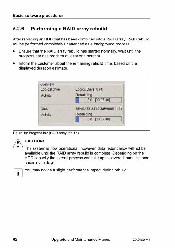
62 Upgrade and Maintenance Manual GX2460 M1
Basic software procedures
5.2.6 Performing a RAID array rebuild
After replacing an HDD that has been combined into a RAID array, RAID rebuild will be performed completely unattended as a background process.
Ê Ensure that the RAID array rebuild has started normally. Wait until the progress bar has reached at least one percent.
Ê Inform the customer about the remaining rebuild time, based on the displayed duration estimate.
Figure 19: Progress bar (RAID array rebuild)
V CAUTION!
The system is now operational, however, data redundancy will not be available until the RAID array rebuild is complete. Depending on the HDD capacity the overall process can take up to several hours, in some cases even days.
I You may notice a slight performance impact during rebuild.
GX2460 M1 Upgrade and Maintenance Manual 63
Basic software procedures
5.2.7 Looking for MAC addresses
The customer needs to know the new address of the controller:
– When replacing the system board with an onboard LAN controller– When adding or replacing a network controller
Different controllers send different addresses:
– LAN controller: MAC (Media Access Control) address
5.2.7.1 Looking for the MAC address of a LAN controller
When replacing a network controller, the MAC (Media Access Control) address will change.
There are several possible locations where these addresses can be found.
Checking the label
Ê If available, check the label on the controller.Beside the part number, you may find the MAC address.
Using an UEFI BIOS
Ê Enter the BIOS setup menu.
Ê Select the System Information menu.
Ê Under Network Controller Details you will find information of MAC addresses of each network controller.The addresses are displayed at the Advanced menu main page.
Or:
Ê Enter the BIOS setup menu.
Ê Select the Advanced menu.The addresses are displayed at the Advanced menu main page.
I Only network controllers supporting the Command Line Protocol (CLP) will be displayed.LAN controller provide the MAC addresses independent on Legacy Boot or UEFI Boot.
For more information see the corresponding BIOS reference manual.
Ê Inform the customer about the new or changed MAC address.
64 Upgrade and Maintenance Manual GX2460 M1
Basic software procedures
5.2.8 Switching off the ID indicator
Ê Press the ID button on the front panel to switch off the ID indicator after the maintenance task has been concluded successfully.
I For more information, see section "Locating the defective server" on page 39.
GX2460 M1 Upgrade and Maintenance Manual 65
6 Power supply unit (PSU)Safety notes
V CAUTION!
● Do not disassemble the PSU. Doing so may cause electric shock.
● Areas around the PSU may remain extremely hot after shutdown. After shutting down the server, wait for hot components to cool down before removing the PSU.
● When installing a PSU, ensure that the connector of the PSU is not damaged or bent.
● The PSU is heavy, so handle it carefully. If you drop it by mistake, injuries may result.
● For more information, see chapter "Important information" on page 27.
6.1 Basic information
AC PSU
The server is equipped with two hot-plug AC PSUs.
In its basic configuration, the server has two PSUs that adjusts automatically to any mains voltage in the range of 100 V - 240 V and 200 - 240 V. The second PSU is installed to serve as a redundant supply. If one PSU fails, the second PSU in the redundant configuration ensures operation can continue uninterrupted and the defective PSU can be replaced during operation (hot-plug).
V CAUTION!
The AC PSU adjusts automatically to any power voltage in the range from 100 V - 240 V (AC PSU 80 PLUS Platinum). You may only operate the server if its rated voltage range corresponds to the local mains voltage.
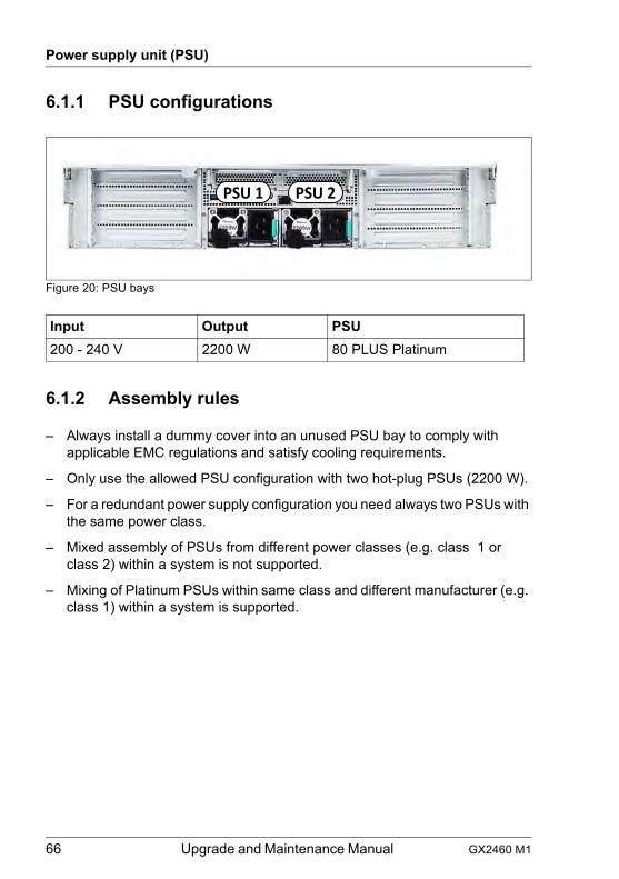
66 Upgrade and Maintenance Manual GX2460 M1
Power supply unit (PSU)
6.1.1 PSU configurations
Figure 20: PSU bays
6.1.2 Assembly rules
– Always install a dummy cover into an unused PSU bay to comply with applicable EMC regulations and satisfy cooling requirements.
– Only use the allowed PSU configuration with two hot-plug PSUs (2200 W).
– For a redundant power supply configuration you need always two PSUs with the same power class.
– Mixed assembly of PSUs from different power classes (e.g. class 1 or class 2) within a system is not supported.
– Mixing of Platinum PSUs within same class and different manufacturer (e.g. class 1) within a system is supported.
Input Output PSU200 - 240 V 2200 W 80 PLUS Platinum
PSU 1 PSU 2
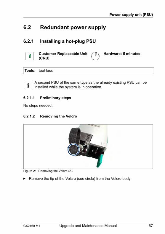
GX2460 M1 Upgrade and Maintenance Manual 67
Power supply unit (PSU)
6.2 Redundant power supply
6.2.1 Installing a hot-plug PSU
I A second PSU of the same type as the already existing PSU can be installed while the system is in operation.
6.2.1.1 Preliminary steps
No steps needed.
6.2.1.2 Removing the Velcro
Figure 21: Removing the Velcro (A)
Ê Remove the tip of the Velcro (see circle) from the Velcro body.
Customer Replaceable Unit(CRU)
Hardware: 5 minutes
Tools: tool-less
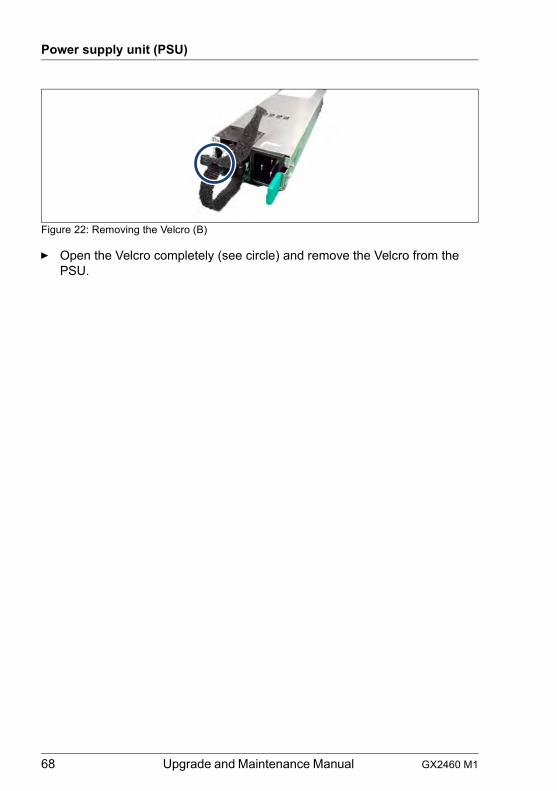
68 Upgrade and Maintenance Manual GX2460 M1
Power supply unit (PSU)
Figure 22: Removing the Velcro (B)
Ê Open the Velcro completely (see circle) and remove the Velcro from the PSU.
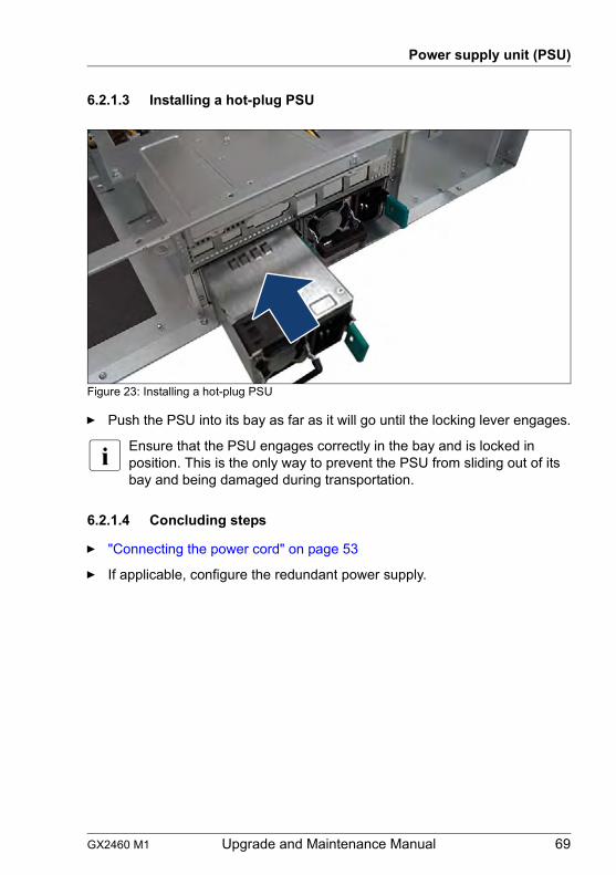
GX2460 M1 Upgrade and Maintenance Manual 69
Power supply unit (PSU)
6.2.1.3 Installing a hot-plug PSU
Figure 23: Installing a hot-plug PSU
Ê Push the PSU into its bay as far as it will go until the locking lever engages.
I Ensure that the PSU engages correctly in the bay and is locked in position. This is the only way to prevent the PSU from sliding out of its bay and being damaged during transportation.
6.2.1.4 Concluding steps
Ê "Connecting the power cord" on page 53
Ê If applicable, configure the redundant power supply.
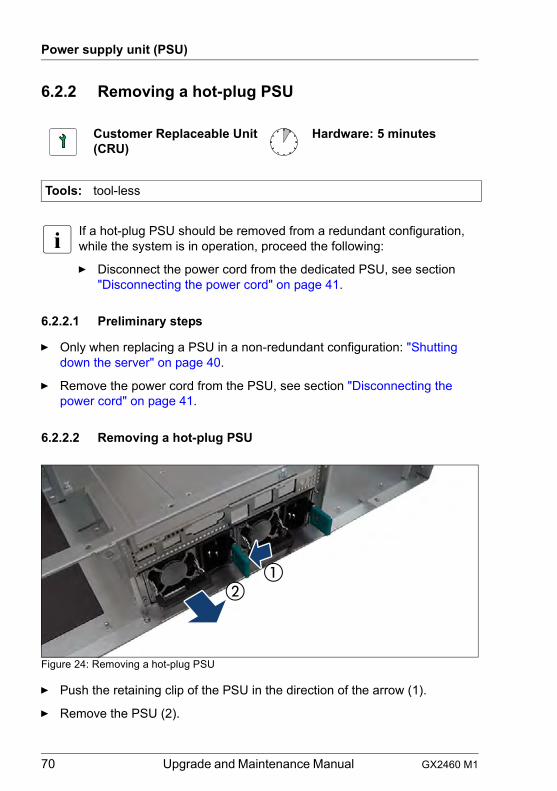
70 Upgrade and Maintenance Manual GX2460 M1
Power supply unit (PSU)
6.2.2 Removing a hot-plug PSU
I If a hot-plug PSU should be removed from a redundant configuration, while the system is in operation, proceed the following:
Ê Disconnect the power cord from the dedicated PSU, see section "Disconnecting the power cord" on page 41.
6.2.2.1 Preliminary steps
Ê Only when replacing a PSU in a non-redundant configuration: "Shutting down the server" on page 40.
Ê Remove the power cord from the PSU, see section "Disconnecting the power cord" on page 41.
6.2.2.2 Removing a hot-plug PSU
Figure 24: Removing a hot-plug PSU
Ê Push the retaining clip of the PSU in the direction of the arrow (1).
Ê Remove the PSU (2).
Customer Replaceable Unit(CRU)
Hardware: 5 minutes
Tools: tool-less
GX2460 M1 Upgrade and Maintenance Manual 71
Power supply unit (PSU)
V CAUTION!
Never leave the bay for the hot-plug PSU empty for more than two minutes during operation. Otherwise, excessive temperatures could damage system components.
6.2.2.3 Concluding steps
Ê No steps needed.
72 Upgrade and Maintenance Manual GX2460 M1
Power supply unit (PSU)
6.2.3 Replacing a hot-plug PSU
V CAUTION!
● When replacing a PSU in a non-redundant PSU configuration, the server must be switched off first.
● Replace the PSU after specifying the one that breaks down at work by revitalization.
6.2.3.1 Preliminary steps
Ê "Locating the defective server" on page 39
Ê Check, which PSU is defective.
A PSU is defective when the PSU status indicator lights orange. For more information, see section "Indicators on hot-plug PSUs" on page 233.
Ê Only when replacing a PSU in a non-redundant configuration: "Shutting down the server" on page 40.
Ê Remove the power cord from the defective PSU, see section "Disconnecting the power cord" on page 41.
6.2.3.2 Removing the defective hot-plug PSU
Ê Remove the PSU, see section "Removing a hot-plug PSU" on page 70.
6.2.3.3 Installing the new hot-plug PSU
Ê Remove the Velcro, see section "Removing the Velcro" on page 67.
Ê Install the PSU, see section "Installing a hot-plug PSU" on page 69.
Customer Replaceable Unit(CRU)
Hardware: 5 minutes
Tools: tool-less
GX2460 M1 Upgrade and Maintenance Manual 73
Power supply unit (PSU)
6.2.3.4 Concluding steps
Ê Connect the power cord to the new PSU and secure it with a cable tie, see section "Connecting the power cord" on page 53.
Ê Only when replacing a PSU in a non-redundant configuration: "Switching on the server" on page 54.
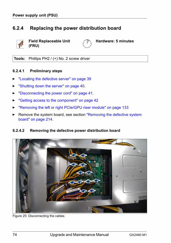
74 Upgrade and Maintenance Manual GX2460 M1
Power supply unit (PSU)
6.2.4 Replacing the power distribution board
6.2.4.1 Preliminary steps
Ê "Locating the defective server" on page 39
Ê "Shutting down the server" on page 40.
Ê "Disconnecting the power cord" on page 41.
Ê "Getting access to the component" on page 42
Ê "Removing the left or right PCIe/GPU riser module" on page 133
Ê Remove the system board, see section "Removing the defective system board" on page 214.
6.2.4.2 Removing the defective power distribution board
Figure 25: Disconnecting the cables
Field Replaceable Unit(FRU)
Hardware: 5 minutes
Tools: Phillips PH2 / (+) No. 2 screw driver
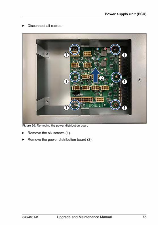
GX2460 M1 Upgrade and Maintenance Manual 75
Power supply unit (PSU)
Ê Disconnect all cables.
Figure 26: Removing the power distribution board
Ê Remove the six screws (1).
Ê Remove the power distribution board (2).
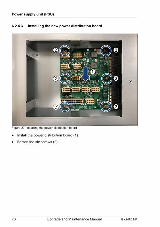
76 Upgrade and Maintenance Manual GX2460 M1
Power supply unit (PSU)
6.2.4.3 Installing the new power distribution board
Figure 27: Installing the power distribution board
Ê Install the power distribution board (1).
Ê Fasten the six screws (2).
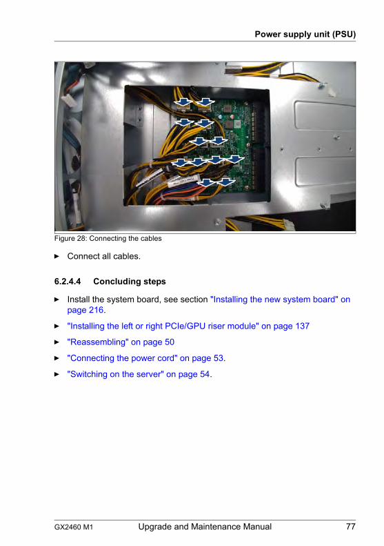
GX2460 M1 Upgrade and Maintenance Manual 77
Power supply unit (PSU)
Figure 28: Connecting the cables
Ê Connect all cables.
6.2.4.4 Concluding steps
Ê Install the system board, see section "Installing the new system board" on page 216.
Ê "Installing the left or right PCIe/GPU riser module" on page 137
Ê "Reassembling" on page 50
Ê "Connecting the power cord" on page 53.
Ê "Switching on the server" on page 54.

78 Upgrade and Maintenance Manual GX2460 M1
Power supply unit (PSU)

GX2460 M1 Upgrade and Maintenance Manual 79
7 Hard disk drive (HDD) and solid state drive (SSD)
Safety notes
V CAUTION!
● Before removing several HDD/SSD modules, make sure that all HDD/SSD modules can be reinstalled into their original bay. Otherwise, data may be lost.
● Do not touch the circuitry on boards or soldered parts. Hold circuit boards by their metallic areas or edges.
● Before removing an HDD, wait for about 30 seconds until the disk has stopped spinning completely.
● When an HDD is starting up, a resonant noise may be audible for a short while. This does not indicate a failure.
● Depending on the operating system, you can configure the write cache settings for the HDDs. If a power failure should occur while the write cache is enabled, cached data may be lost.
● When disposing of, transferring, or returning an HDD or SSD, wipe out the data on the drive for your own security.
● Rough handling of HDDs may damage the stored data. To cope with any unexpected problems, always back up important data. When backing up data to another HDD, you should make backups on a file or partition basis.
● Be careful not to hit the HDD or bring it into contact with metallic objects.
● Handle the HDD and SSD on a shock and vibration free surface.
● Do not use the HDD and SSD in extremely hot or cold locations, or locations with extreme temperature changes.
● Never attempt to disassemble the HDD or SSD.
● For more information, see chapter "Important information" on page 27.
80 Upgrade and Maintenance Manual GX2460 M1
Hard disk drive (HDD) and solid state drive (SSD)
7.1 Basic information
The HDD or SSD and the installation frame together make up the HDD module or SSD module.
The server is shipped with one of the following HDD or SSD subsystems:
– 2.5-inch/3.5-inch HDD/SSD subsystem:
Up to eight 2.5-inch SAS/SATA HDD/SSD modules can be installed.
I For information on RAID controllers controlling the HDD/SSD modules, see chapter "Expansion cards and riser modules" on page 109.
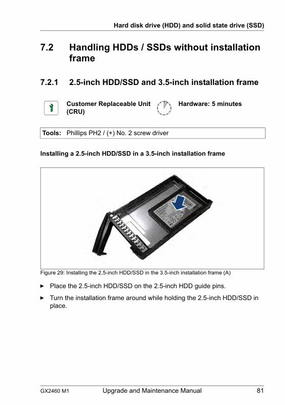
GX2460 M1 Upgrade and Maintenance Manual 81
Hard disk drive (HDD) and solid state drive (SSD)
7.2 Handling HDDs / SSDs without installation frame
7.2.1 2.5-inch HDD/SSD and 3.5-inch installation frame
Installing a 2.5-inch HDD/SSD in a 3.5-inch installation frame
Figure 29: Installing the 2.5-inch HDD/SSD in the 3.5-inch installation frame (A)
Ê Place the 2.5-inch HDD/SSD on the 2.5-inch HDD guide pins.
Ê Turn the installation frame around while holding the 2.5-inch HDD/SSD in place.
Customer Replaceable Unit(CRU)
Hardware: 5 minutes
Tools: Phillips PH2 / (+) No. 2 screw driver
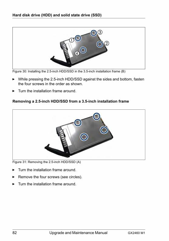
82 Upgrade and Maintenance Manual GX2460 M1
Hard disk drive (HDD) and solid state drive (SSD)
Figure 30: Installing the 2.5-inch HDD/SSD in the 3.5-inch installation frame (B)
Ê While pressing the 2.5-inch HDD/SSD against the sides and bottom, fasten the four screws in the order as shown.
Ê Turn the installation frame around.
Removing a 2.5-inch HDD/SSD from a 3.5-inch installation frame
Figure 31: Removing the 2.5-inch HDD/SSD (A)
Ê Turn the installation frame around.
Ê Remove the four screws (see circles).
Ê Turn the installation frame around.
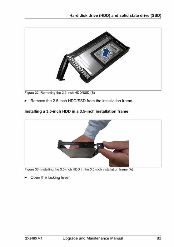
GX2460 M1 Upgrade and Maintenance Manual 83
Hard disk drive (HDD) and solid state drive (SSD)
Figure 32: Removing the 2.5-inch HDD/SSD (B)
Ê Remove the 2.5-inch HDD/SSD from the installation frame.
Installing a 3.5-inch HDD in a 3.5-inch installation frame
Figure 33: Installing the 3.5-inch HDD in the 3.5-inch installation frame (A)
Ê Open the locking lever.
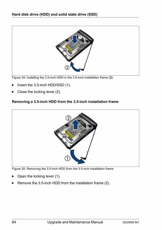
84 Upgrade and Maintenance Manual GX2460 M1
Hard disk drive (HDD) and solid state drive (SSD)
Figure 34: Installing the 3.5-inch HDD in the 3.5-inch installation frame (B)
Ê Insert the 3.5-inch HDD/SSD (1).
Ê Close the locking lever (2).
Removing a 3.5-inch HDD from the 3.5-inch installation frame
Figure 35: Removing the 3.5-inch HDD from the 3.5-inch installation frame
Ê Open the locking lever (1).
Ê Remove the 3.5-inch HDD from the installation frame (2).
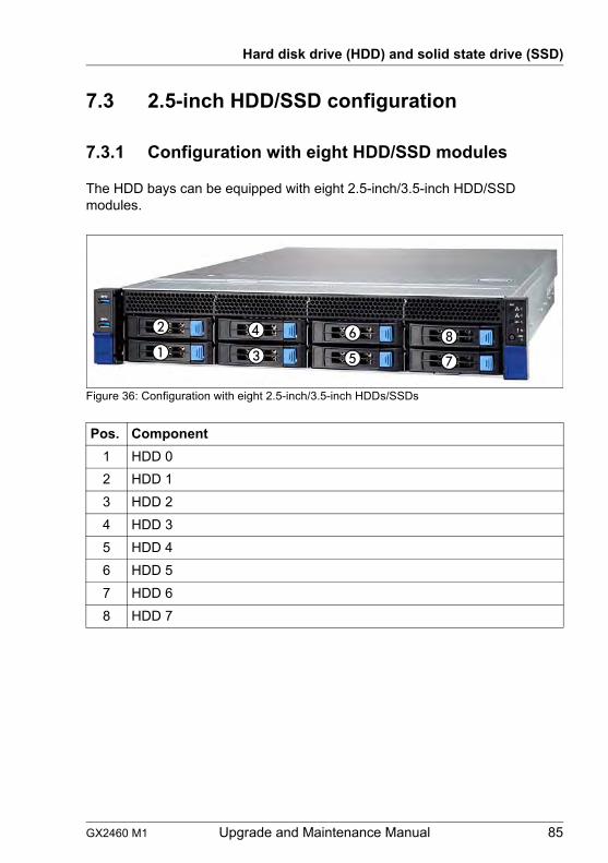
GX2460 M1 Upgrade and Maintenance Manual 85
Hard disk drive (HDD) and solid state drive (SSD)
7.3 2.5-inch HDD/SSD configuration
7.3.1 Configuration with eight HDD/SSD modules
The HDD bays can be equipped with eight 2.5-inch/3.5-inch HDD/SSD modules.
Figure 36: Configuration with eight 2.5-inch/3.5-inch HDDs/SSDs
Pos. Component1 HDD 02 HDD 13 HDD 24 HDD 35 HDD 46 HDD 57 HDD 68 HDD 7
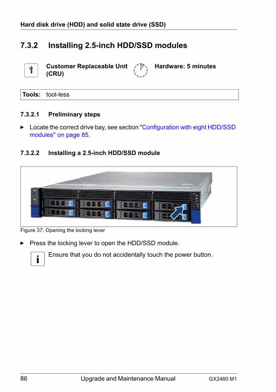
86 Upgrade and Maintenance Manual GX2460 M1
Hard disk drive (HDD) and solid state drive (SSD)
7.3.2 Installing 2.5-inch HDD/SSD modules
7.3.2.1 Preliminary steps
Ê Locate the correct drive bay, see section "Configuration with eight HDD/SSD modules" on page 85.
7.3.2.2 Installing a 2.5-inch HDD/SSD module
Figure 37: Opening the locking lever
Ê Press the locking lever to open the HDD/SSD module.
I Ensure that you do not accidentally touch the power button.
Customer Replaceable Unit(CRU)
Hardware: 5 minutes
Tools: tool-less
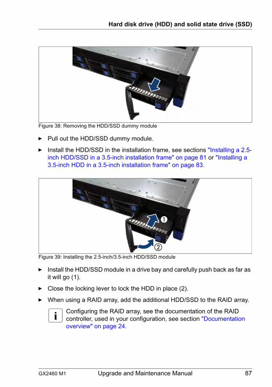
GX2460 M1 Upgrade and Maintenance Manual 87
Hard disk drive (HDD) and solid state drive (SSD)
Figure 38: Removing the HDD/SSD dummy module
Ê Pull out the HDD/SSD dummy module.
Ê Install the HDD/SSD in the installation frame, see sections "Installing a 2.5-inch HDD/SSD in a 3.5-inch installation frame" on page 81 or "Installing a 3.5-inch HDD in a 3.5-inch installation frame" on page 83.
Figure 39: Installing the 2.5-inch/3.5-inch HDD/SSD module
Ê Install the HDD/SSD module in a drive bay and carefully push back as far as it will go (1).
Ê Close the locking lever to lock the HDD in place (2).
Ê When using a RAID array, add the additional HDD/SSD to the RAID array.
I Configuring the RAID array, see the documentation of the RAID controller, used in your configuration, see section "Documentation overview" on page 24.
88 Upgrade and Maintenance Manual GX2460 M1
Hard disk drive (HDD) and solid state drive (SSD)
7.3.2.3 Concluding steps
Ê No steps needed.
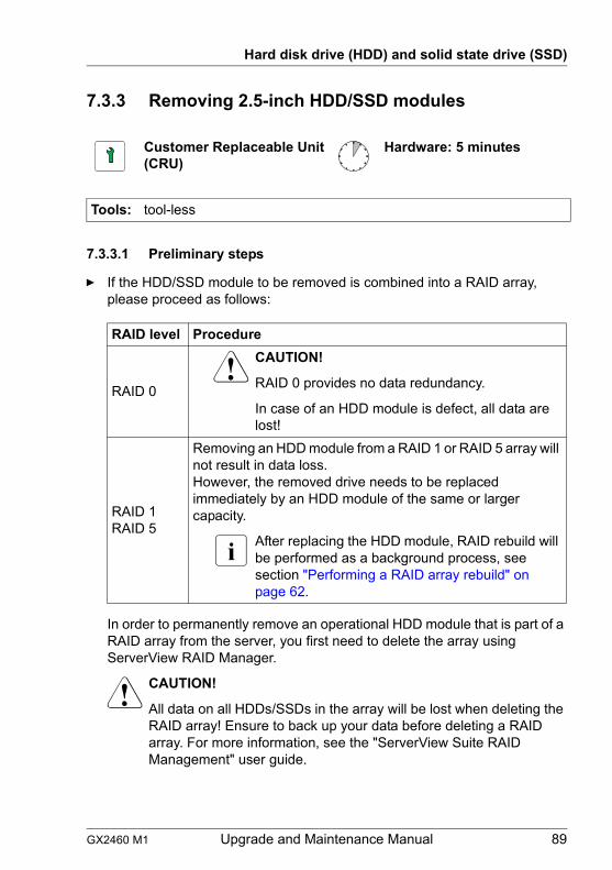
GX2460 M1 Upgrade and Maintenance Manual 89
Hard disk drive (HDD) and solid state drive (SSD)
7.3.3 Removing 2.5-inch HDD/SSD modules
7.3.3.1 Preliminary steps
Ê If the HDD/SSD module to be removed is combined into a RAID array, please proceed as follows:
In order to permanently remove an operational HDD module that is part of a RAID array from the server, you first need to delete the array using ServerView RAID Manager.
V CAUTION!
All data on all HDDs/SSDs in the array will be lost when deleting the RAID array! Ensure to back up your data before deleting a RAID array. For more information, see the "ServerView Suite RAID Management" user guide.
Customer Replaceable Unit(CRU)
Hardware: 5 minutes
Tools: tool-less
RAID level Procedure
RAID 0
V CAUTION!
RAID 0 provides no data redundancy.
In case of an HDD module is defect, all data are lost!
RAID 1RAID 5
Removing an HDD module from a RAID 1 or RAID 5 array will not result in data loss.However, the removed drive needs to be replaced immediately by an HDD module of the same or larger capacity.
I After replacing the HDD module, RAID rebuild will be performed as a background process, see section "Performing a RAID array rebuild" on page 62.
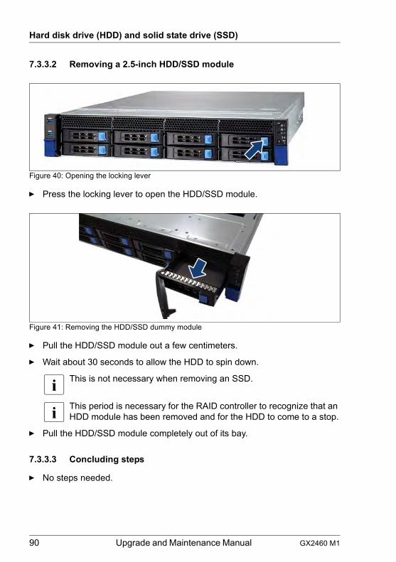
90 Upgrade and Maintenance Manual GX2460 M1
Hard disk drive (HDD) and solid state drive (SSD)
7.3.3.2 Removing a 2.5-inch HDD/SSD module
Figure 40: Opening the locking lever
Ê Press the locking lever to open the HDD/SSD module.
Figure 41: Removing the HDD/SSD dummy module
Ê Pull the HDD/SSD module out a few centimeters.
Ê Wait about 30 seconds to allow the HDD to spin down.
I This is not necessary when removing an SSD.
I This period is necessary for the RAID controller to recognize that an HDD module has been removed and for the HDD to come to a stop.
Ê Pull the HDD/SSD module completely out of its bay.
7.3.3.3 Concluding steps
Ê No steps needed.
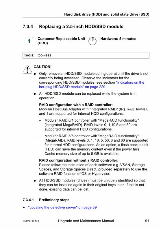
GX2460 M1 Upgrade and Maintenance Manual 91
Hard disk drive (HDD) and solid state drive (SSD)
7.3.4 Replacing a 2.5-inch HDD/SSD module
V CAUTION!
● Only remove an HDD/SSD module during operation if the drive is not currently being accessed. Observe the indicators for the corresponding HDD/SSD modules, see section "Indicators on the hot-plug HDD/SSD module" on page 229.
● An HDD/SSD module can be replaced while the system is in operation.
RAID configuration with a RAID controller:Modular Host Bus Adapter with "Integrated RAID" (IR). RAID levels 0 and 1 are supported for internal HDD configurations.
– Modular RAID 0/1 controller with "MegaRAID functionality" (integrated MegaRAID). RAID levels 0, 1,10,5 and 50 are supported for internal HDD configurations.
– Modular RAID 5/6 controller with "MegaRAID functionality" (MegaRAID). RAID levels 0, 1, 10, 5, 50, 6 and 60 are supported for internal HDD configurations. As an option, a flash backup unit (FBU) can save the memory content even if the power fails. Cache memory size of up to 8 GB is available.
RAID configuration without a RAID controller:Please follow the instruction of each software e.g. VSAN, Storage Spaces, and Storage Spaces Direct, provided separately to use the software RAID function of OS or Hypervisor.
● All HDD/SSD modules (drives) must be uniquely identified so that they can be installed again in their original bays later. If this is not done, existing data can be lost.
7.3.4.1 Preliminary steps
Ê "Locating the defective server" on page 39
Customer Replaceable Unit(CRU)
Hardware: 5 minutes
Tools: tool-less
92 Upgrade and Maintenance Manual GX2460 M1
Hard disk drive (HDD) and solid state drive (SSD)
Ê "Locating the defective component" on page 39
7.3.4.2 Removing the defective 2.5-inch HDD/SSD module
Ê Remove the HDD/SSD module, see section "Removing a 2.5-inch HDD/SSD module" on page 90.
Ê If applicable, remove the HDD/SSD from the installation frame, see section "Handling HDDs / SSDs without installation frame" on page 81.
7.3.4.3 Installing the new 2.5-inch HDD/SSD module
Ê If applicable, install the HDD/SSD in the installation frame, see section "Handling HDDs / SSDs without installation frame" on page 81.
Ê Install the HDD/SSD module, see section "Installing 2.5-inch HDD/SSD modules" on page 86.
7.3.4.4 Concluding steps
Ê If the HDD/SSD is configured in a RAID configuration with a RAID level higher than "0", the rebuild will start automatically, see section "Performing a RAID array rebuild" on page 62.
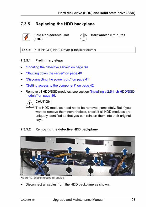
GX2460 M1 Upgrade and Maintenance Manual 93
Hard disk drive (HDD) and solid state drive (SSD)
7.3.5 Replacing the HDD backplane
7.3.5.1 Preliminary steps
Ê "Locating the defective server" on page 39
Ê "Shutting down the server" on page 40
Ê "Disconnecting the power cord" on page 41
Ê "Getting access to the component" on page 42
Ê Remove all HDD/SSD modules, see section "Installing a 2.5-inch HDD/SSD module" on page 86.
V CAUTION!
The HDD modules need not to be removed completely. But if you want to remove them nevertheless, check if all HDD modules are uniquely identified so that you can reinsert them into their original bays.
7.3.5.2 Removing the defective HDD backplane
Figure 42: Disconnecting all cables
Ê Disconnect all cables from the HDD backplane as shown.
Field Replaceable Unit(FRU)
Hardware: 10 minutes
Tools: Plus PH2/(+) No.2 Driver (Stabilizer driver)
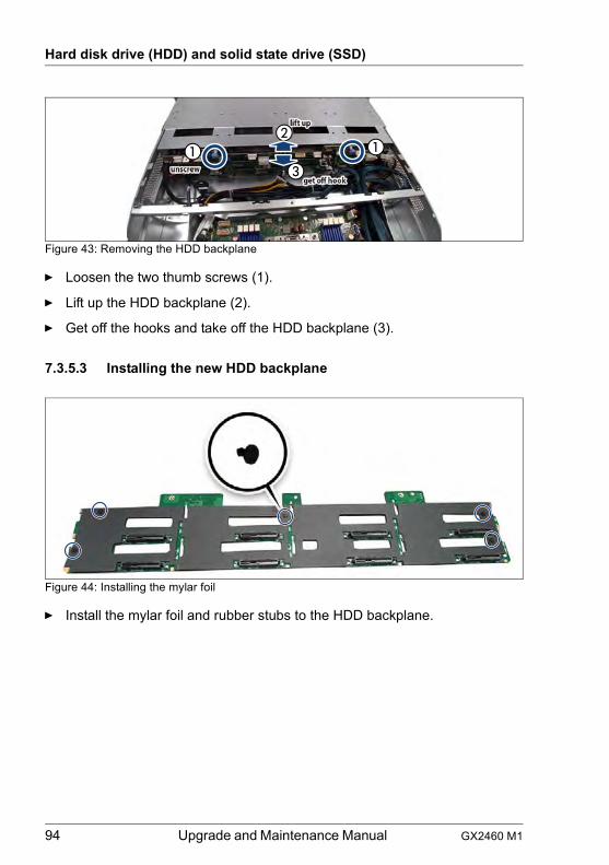
94 Upgrade and Maintenance Manual GX2460 M1
Hard disk drive (HDD) and solid state drive (SSD)
Figure 43: Removing the HDD backplane
Ê Loosen the two thumb screws (1).
Ê Lift up the HDD backplane (2).
Ê Get off the hooks and take off the HDD backplane (3).
7.3.5.3 Installing the new HDD backplane
Figure 44: Installing the mylar foil
Ê Install the mylar foil and rubber stubs to the HDD backplane.
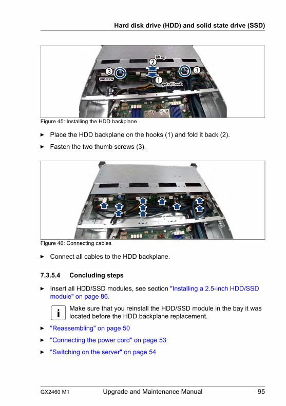
GX2460 M1 Upgrade and Maintenance Manual 95
Hard disk drive (HDD) and solid state drive (SSD)
Figure 45: Installing the HDD backplane
Ê Place the HDD backplane on the hooks (1) and fold it back (2).
Ê Fasten the two thumb screws (3).
Figure 46: Connecting cables
Ê Connect all cables to the HDD backplane.
7.3.5.4 Concluding steps
Ê Insert all HDD/SSD modules, see section "Installing a 2.5-inch HDD/SSD module" on page 86.
I Make sure that you reinstall the HDD/SSD module in the bay it was located before the HDD backplane replacement.
Ê "Reassembling" on page 50
Ê "Connecting the power cord" on page 53
Ê "Switching on the server" on page 54
96 Upgrade and Maintenance Manual GX2460 M1
Hard disk drive (HDD) and solid state drive (SSD)
GX2460 M1 Upgrade and Maintenance Manual 97
8 FansSafety notes
V CAUTION!
● Do not damage or modify internal cables or devices. Doing so may cause a device failure, fire, or electric shock.
● Devices and components inside the server remain hot after shutdown. After shutting down the server, wait for hot components to cool down before installing or removing internal options.
● Circuit boards and soldered parts of internal options are exposed and can be damaged by static electricity. Always discharge static build-up (e.g. by touching a grounded object) before handling electrostatic-sensitive devices (ESDs).
● Do not touch the circuitry on boards or soldered parts. Hold circuit boards by their metallic areas or edges.
● If devices are installed or disassembled using methods other than those outlined in this chapter, the warranty will be invalidated.
● The procedure of installation on this notes might change depending on a configuration of options.
● For more information, see chapter "Important information" on page 27.
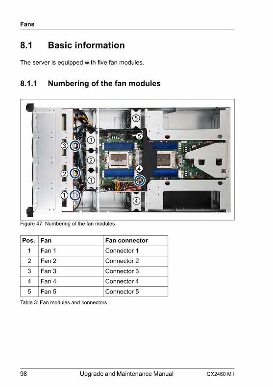
98 Upgrade and Maintenance Manual GX2460 M1
Fans
8.1 Basic information
The server is equipped with five fan modules.
8.1.1 Numbering of the fan modules
Figure 47: Numbering of the fan modules
Pos. Fan Fan connector1 Fan 1 Connector 12 Fan 2 Connector 23 Fan 3 Connector 34 Fan 4 Connector 45 Fan 5 Connector 5
Table 3: Fan modules and connectors
GX2460 M1 Upgrade and Maintenance Manual 99
Fans
8.2 Replacing a fan module
8.2.1 Preliminary steps
Ê "Locating the defective server" on page 39
Ê "Locating the defective component" on page 39
Ê "Shutting down the server" on page 40
Ê "Getting access to the component" on page 42
Ê "Removing the rear top cover" on page 47
Ê "Removing the front top cover" on page 46
8.2.2 Removing a defective fan module (Fan 1/2/3)
Ê Disconnect the corresponding fan cable from the HDD backplane (see figure 47).
Ê Lift the system fan out of the chassis.
Customer Replaceable Unit(CRU)
Hardware: 5 minutes
Tools: Phillips PH2 / (+) No. 2 screw driver
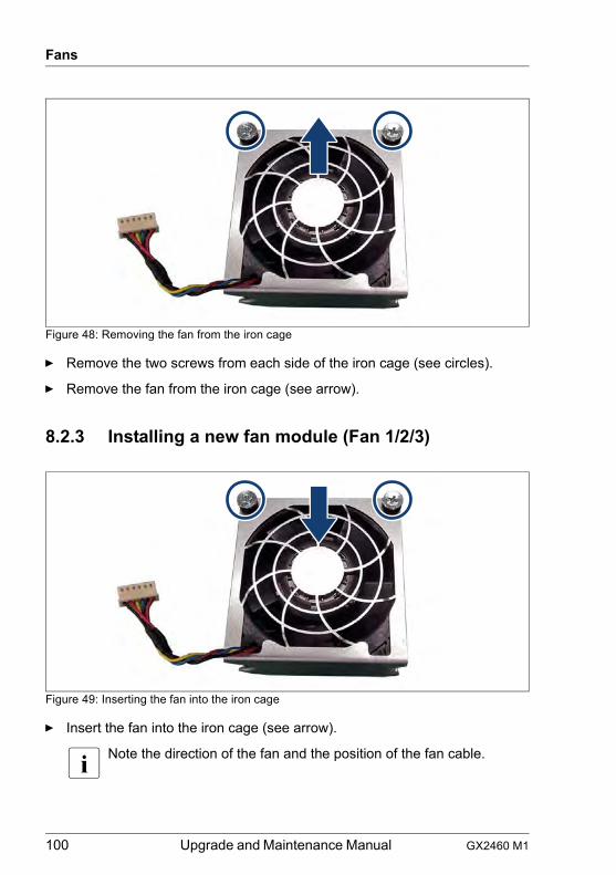
100 Upgrade and Maintenance Manual GX2460 M1
Fans
Figure 48: Removing the fan from the iron cage
Ê Remove the two screws from each side of the iron cage (see circles).
Ê Remove the fan from the iron cage (see arrow).
8.2.3 Installing a new fan module (Fan 1/2/3)
Figure 49: Inserting the fan into the iron cage
Ê Insert the fan into the iron cage (see arrow).
I Note the direction of the fan and the position of the fan cable.
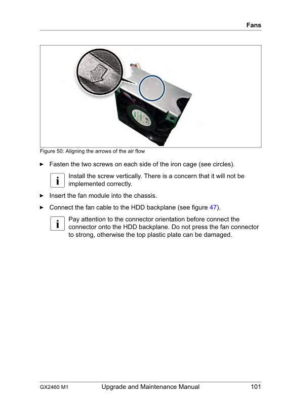
GX2460 M1 Upgrade and Maintenance Manual 101
Fans
Figure 50: Aligning the arrows of the air flow
Ê Fasten the two screws on each side of the iron cage (see circles).
I Install the screw vertically. There is a concern that it will not be implemented correctly.
Ê Insert the fan module into the chassis.
Ê Connect the fan cable to the HDD backplane (see figure 47).
I Pay attention to the connector orientation before connect the connector onto the HDD backplane. Do not press the fan connector to strong, otherwise the top plastic plate can be damaged.
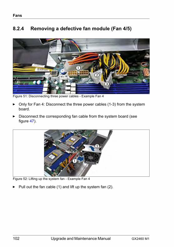
102 Upgrade and Maintenance Manual GX2460 M1
Fans
8.2.4 Removing a defective fan module (Fan 4/5)
Figure 51: Disconnecting three power cables - Example Fan 4
Ê Only for Fan 4: Disconnect the three power cables (1-3) from the system board.
Ê Disconnect the corresponding fan cable from the system board (see figure 47).
Figure 52: Lifting up the system fan - Example Fan 4
Ê Pull out the fan cable (1) and lift up the system fan (2).
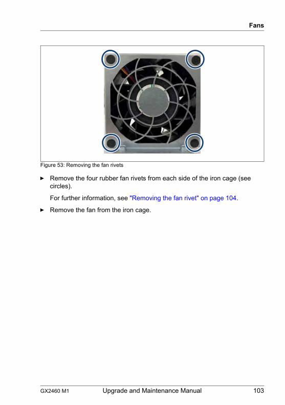
GX2460 M1 Upgrade and Maintenance Manual 103
Fans
Figure 53: Removing the fan rivets
Ê Remove the four rubber fan rivets from each side of the iron cage (see circles).
For further information, see "Removing the fan rivet" on page 104.
Ê Remove the fan from the iron cage.
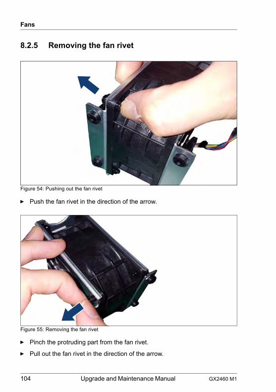
104 Upgrade and Maintenance Manual GX2460 M1
Fans
8.2.5 Removing the fan rivet
Figure 54: Pushing out the fan rivet
Ê Push the fan rivet in the direction of the arrow.
Figure 55: Removing the fan rivet
Ê Pinch the protruding part from the fan rivet.
Ê Pull out the fan rivet in the direction of the arrow.
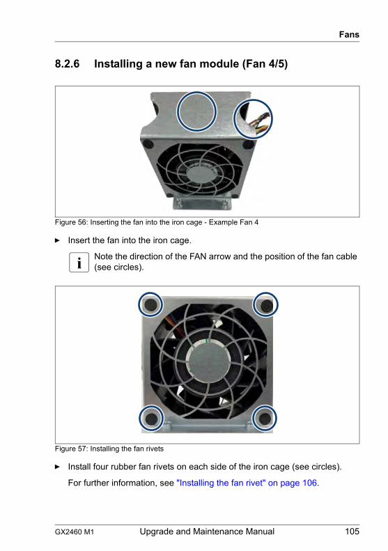
GX2460 M1 Upgrade and Maintenance Manual 105
Fans
8.2.6 Installing a new fan module (Fan 4/5)
Figure 56: Inserting the fan into the iron cage - Example Fan 4
Ê Insert the fan into the iron cage.
I Note the direction of the FAN arrow and the position of the fan cable (see circles).
Figure 57: Installing the fan rivets
Ê Install four rubber fan rivets on each side of the iron cage (see circles).
For further information, see "Installing the fan rivet" on page 106.
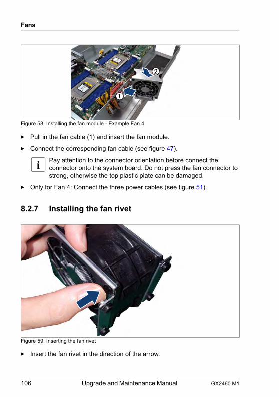
106 Upgrade and Maintenance Manual GX2460 M1
Fans
Figure 58: Installing the fan module - Example Fan 4
Ê Pull in the fan cable (1) and insert the fan module.
Ê Connect the corresponding fan cable (see figure 47).
I Pay attention to the connector orientation before connect the connector onto the system board. Do not press the fan connector to strong, otherwise the top plastic plate can be damaged.
Ê Only for Fan 4: Connect the three power cables (see figure 51).
8.2.7 Installing the fan rivet
Figure 59: Inserting the fan rivet
Ê Insert the fan rivet in the direction of the arrow.
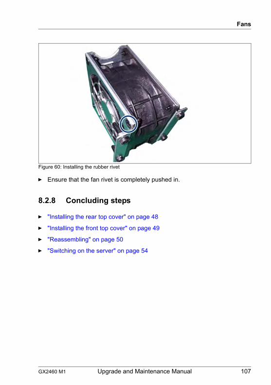
GX2460 M1 Upgrade and Maintenance Manual 107
Fans
Figure 60: Installing the rubber rivet
Ê Ensure that the fan rivet is completely pushed in.
8.2.8 Concluding steps
Ê "Installing the rear top cover" on page 48
Ê "Installing the front top cover" on page 49
Ê "Reassembling" on page 50
Ê "Switching on the server" on page 54
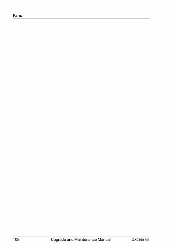
108 Upgrade and Maintenance Manual GX2460 M1
Fans
GX2460 M1 Upgrade and Maintenance Manual 109
9 Expansion cards and riser modules
Safety notes
V CAUTION!
● Do not damage or modify internal cables or devices. Doing so may cause a device failure, fire, or electric shock.
● Devices and components inside the server remain hot after shutdown. After shutting down the server, wait for hot components to cool down before installing or removing internal options.
● Circuit boards and soldered parts of internal options are exposed and can be damaged by static electricity. Always discharge static build-up (e.g. by touching a grounded object) before handling electrostatic-sensitive devices (ESDs).
● Do not touch the circuitry on boards or soldered parts. Hold circuit boards by their metallic areas or edges.
● If devices are installed or disassembled using methods other than those outlined in this chapter, the warranty will be invalidated.
● For more information, see chapter "Important information" on page 27.
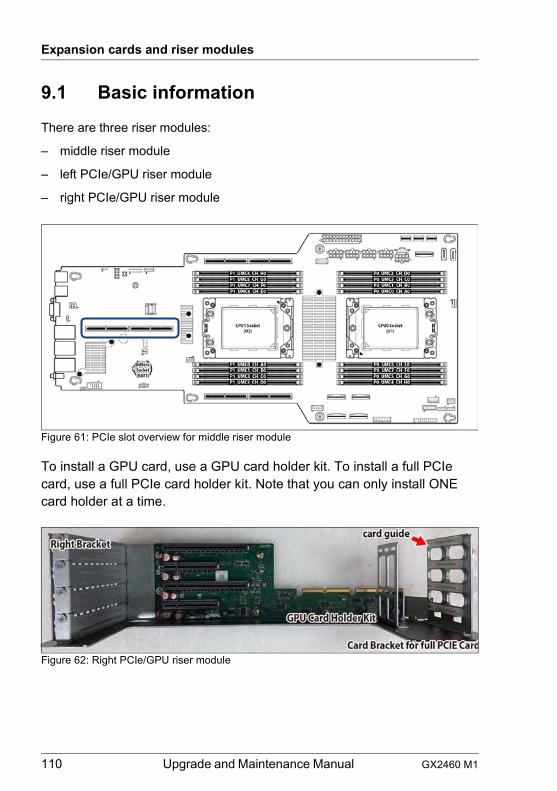
110 Upgrade and Maintenance Manual GX2460 M1
Expansion cards and riser modules
9.1 Basic information
There are three riser modules:
– middle riser module
– left PCIe/GPU riser module
– right PCIe/GPU riser module
Figure 61: PCIe slot overview for middle riser module
To install a GPU card, use a GPU card holder kit. To install a full PCIe card, use a full PCIe card holder kit. Note that you can only install ONE card holder at a time.
Figure 62: Right PCIe/GPU riser module
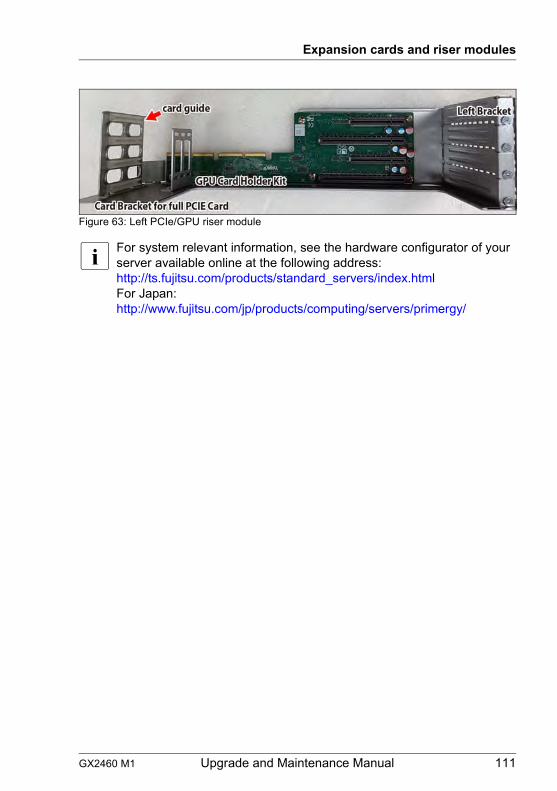
GX2460 M1 Upgrade and Maintenance Manual 111
Expansion cards and riser modules
Figure 63: Left PCIe/GPU riser module
I For system relevant information, see the hardware configurator of your server available online at the following address:http://ts.fujitsu.com/products/standard_servers/index.html For Japan:http://www.fujitsu.com/jp/products/computing/servers/primergy/
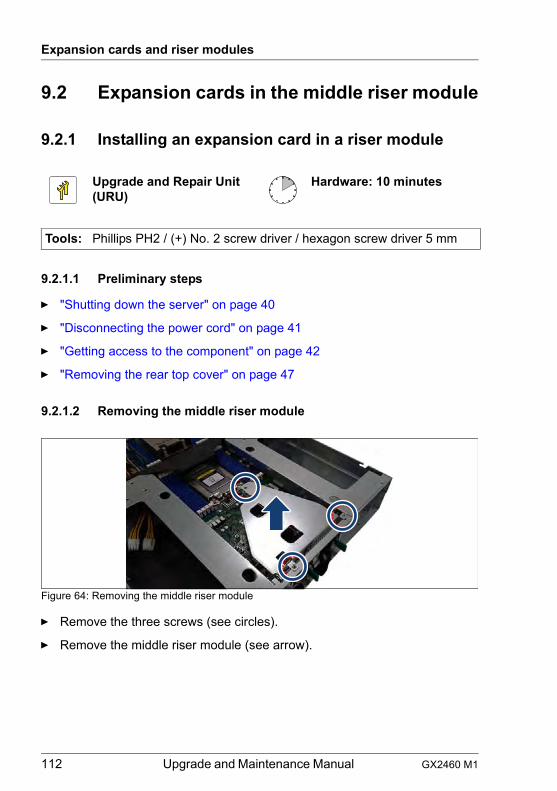
112 Upgrade and Maintenance Manual GX2460 M1
Expansion cards and riser modules
9.2 Expansion cards in the middle riser module
9.2.1 Installing an expansion card in a riser module
9.2.1.1 Preliminary steps
Ê "Shutting down the server" on page 40
Ê "Disconnecting the power cord" on page 41
Ê "Getting access to the component" on page 42
Ê "Removing the rear top cover" on page 47
9.2.1.2 Removing the middle riser module
Figure 64: Removing the middle riser module
Ê Remove the three screws (see circles).
Ê Remove the middle riser module (see arrow).
Upgrade and Repair Unit(URU)
Hardware: 10 minutes
Tools: Phillips PH2 / (+) No. 2 screw driver / hexagon screw driver 5 mm
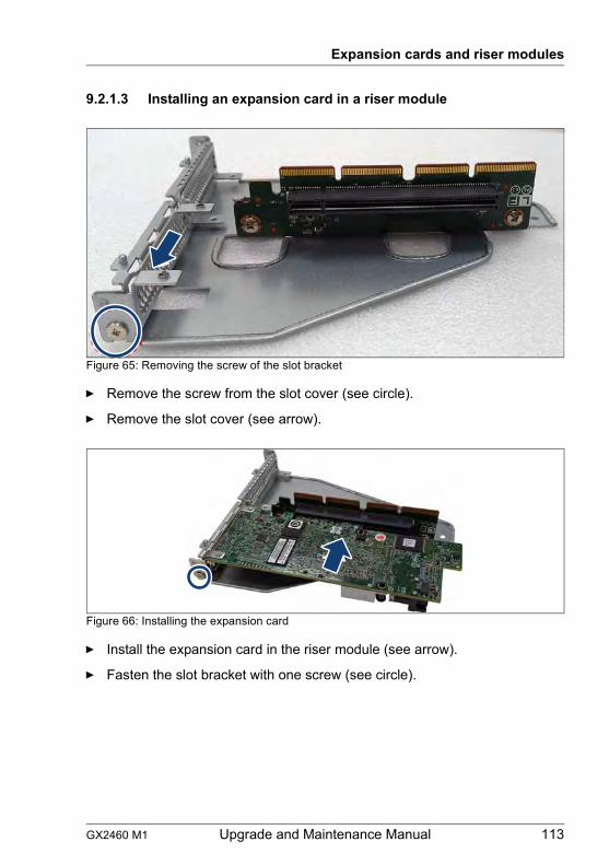
GX2460 M1 Upgrade and Maintenance Manual 113
Expansion cards and riser modules
9.2.1.3 Installing an expansion card in a riser module
Figure 65: Removing the screw of the slot bracket
Ê Remove the screw from the slot cover (see circle).
Ê Remove the slot cover (see arrow).
Figure 66: Installing the expansion card
Ê Install the expansion card in the riser module (see arrow).
Ê Fasten the slot bracket with one screw (see circle).

114 Upgrade and Maintenance Manual GX2460 M1
Expansion cards and riser modules
9.2.1.4 Installing the middle riser module
Figure 67: Installing the middle riser module
Ê Install the riser module in the direction of the arrow.
Ê Fasten the three screws (see circles).
9.2.1.5 Concluding steps
Ê "Installing the rear top cover" on page 48
Ê "Reassembling" on page 50
Ê "Connecting the power cord" on page 53
Ê "Switching on the server" on page 54
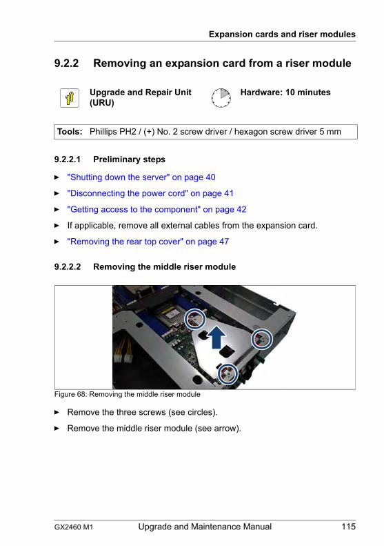
GX2460 M1 Upgrade and Maintenance Manual 115
Expansion cards and riser modules
9.2.2 Removing an expansion card from a riser module
9.2.2.1 Preliminary steps
Ê "Shutting down the server" on page 40
Ê "Disconnecting the power cord" on page 41
Ê "Getting access to the component" on page 42
Ê If applicable, remove all external cables from the expansion card.
Ê "Removing the rear top cover" on page 47
9.2.2.2 Removing the middle riser module
Figure 68: Removing the middle riser module
Ê Remove the three screws (see circles).
Ê Remove the middle riser module (see arrow).
Upgrade and Repair Unit(URU)
Hardware: 10 minutes
Tools: Phillips PH2 / (+) No. 2 screw driver / hexagon screw driver 5 mm
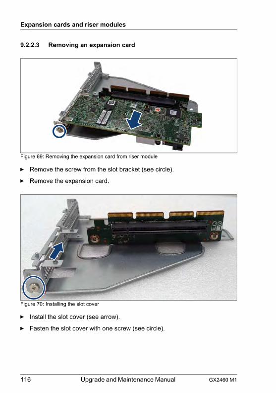
116 Upgrade and Maintenance Manual GX2460 M1
Expansion cards and riser modules
9.2.2.3 Removing an expansion card
Figure 69: Removing the expansion card from riser module
Ê Remove the screw from the slot bracket (see circle).
Ê Remove the expansion card.
Figure 70: Installing the slot cover
Ê Install the slot cover (see arrow).
Ê Fasten the slot cover with one screw (see circle).
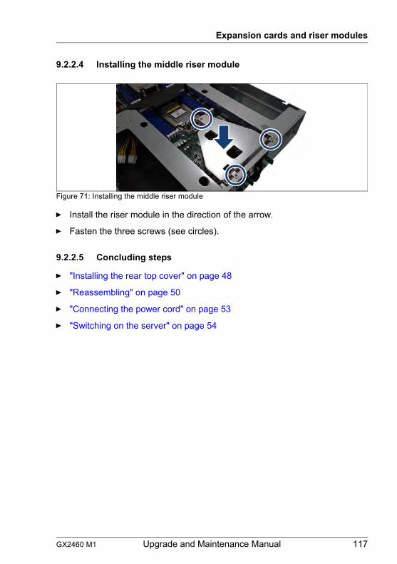
GX2460 M1 Upgrade and Maintenance Manual 117
Expansion cards and riser modules
9.2.2.4 Installing the middle riser module
Figure 71: Installing the middle riser module
Ê Install the riser module in the direction of the arrow.
Ê Fasten the three screws (see circles).
9.2.2.5 Concluding steps
Ê "Installing the rear top cover" on page 48
Ê "Reassembling" on page 50
Ê "Connecting the power cord" on page 53
Ê "Switching on the server" on page 54
118 Upgrade and Maintenance Manual GX2460 M1
Expansion cards and riser modules
9.2.3 Replacing an expansion card in a riser module
9.2.3.1 Preliminary steps
Ê "Locating the defective server" on page 39
Ê "Shutting down the server" on page 40
Ê "Disconnecting the power cord" on page 41
Ê "Removing the rear top cover" on page 47
Ê "Getting access to the component" on page 42
Ê "Removing the rear top cover" on page 47
Ê If applicable, disconnect internal cables from the expansion card.
9.2.3.2 Removing the defective expansion card
Ê Remove the riser module, see section "Removing the middle riser module" on page 112.
Ê Remove the defective expansion card, see section "Removing an expansion card" on page 116.
9.2.3.3 Installing the new expansion card
Ê Install the new expansion card, see section "Installing an expansion card in a riser module" on page 113.
Ê Install the riser module, see section "Installing the middle riser module" on page 114.
Upgrade and Repair Unit(URU)
Hardware: 15 minutes
Tools: Phillips PH2 / (+) No. 2 screw driver / hexagon screw driver 5 mm
GX2460 M1 Upgrade and Maintenance Manual 119
Expansion cards and riser modules
9.2.3.4 Concluding steps
Ê If applicable, connect internal cables to the expansion card.
Ê "Installing the rear top cover" on page 48
Ê "Reassembling" on page 50
Ê "Connecting the power cord" on page 53
Ê "Switching on the server" on page 54
120 Upgrade and Maintenance Manual GX2460 M1
Expansion cards and riser modules
9.2.4 Replacing a riser card
9.2.4.1 Preliminary steps
Ê "Locating the defective server" on page 39
Ê "Shutting down the server" on page 40
Ê "Disconnecting the power cord" on page 41
Ê "Removing the rear top cover" on page 47
Ê "Getting access to the component" on page 42
Ê "Removing the rear top cover" on page 47
Ê If applicable, disconnect internal cables from the expansion card.
9.2.4.2 Removing defective the riser card
Ê Remove the riser module, see section "Removing the middle riser module" on page 112.
Ê Remove the expansion card, see section "Removing an expansion card" on page 116.
Upgrade and Repair Unit(URU)
Hardware: 15 minutes
Tools: Phillips PH2 / (+) No. 2 screw driver / hexagon screw driver 5 mm
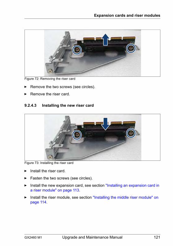
GX2460 M1 Upgrade and Maintenance Manual 121
Expansion cards and riser modules
Figure 72: Removing the riser card
Ê Remove the two screws (see circles).
Ê Remove the riser card.
9.2.4.3 Installing the new riser card
Figure 73: Installing the riser card
Ê Install the riser card.
Ê Fasten the two screws (see circles).
Ê Install the new expansion card, see section "Installing an expansion card in a riser module" on page 113.
Ê Install the riser module, see section "Installing the middle riser module" on page 114.
122 Upgrade and Maintenance Manual GX2460 M1
Expansion cards and riser modules
9.2.4.4 Concluding steps
Ê If applicable, connect internal cables to the expansion card.
Ê "Installing the rear top cover" on page 48
Ê "Reassembling" on page 50
Ê "Connecting the power cord" on page 53
Ê "Switching on the server" on page 54
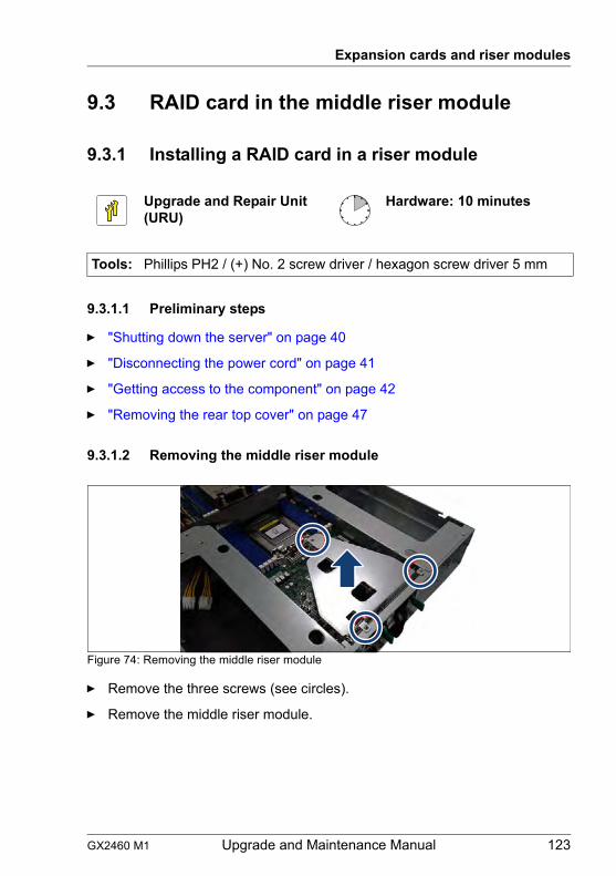
GX2460 M1 Upgrade and Maintenance Manual 123
Expansion cards and riser modules
9.3 RAID card in the middle riser module
9.3.1 Installing a RAID card in a riser module
9.3.1.1 Preliminary steps
Ê "Shutting down the server" on page 40
Ê "Disconnecting the power cord" on page 41
Ê "Getting access to the component" on page 42
Ê "Removing the rear top cover" on page 47
9.3.1.2 Removing the middle riser module
Figure 74: Removing the middle riser module
Ê Remove the three screws (see circles).
Ê Remove the middle riser module.
Upgrade and Repair Unit(URU)
Hardware: 10 minutes
Tools: Phillips PH2 / (+) No. 2 screw driver / hexagon screw driver 5 mm
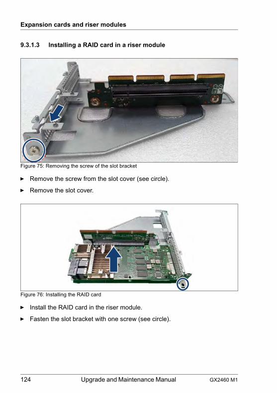
124 Upgrade and Maintenance Manual GX2460 M1
Expansion cards and riser modules
9.3.1.3 Installing a RAID card in a riser module
Figure 75: Removing the screw of the slot bracket
Ê Remove the screw from the slot cover (see circle).
Ê Remove the slot cover.
Figure 76: Installing the RAID card
Ê Install the RAID card in the riser module.
Ê Fasten the slot bracket with one screw (see circle).
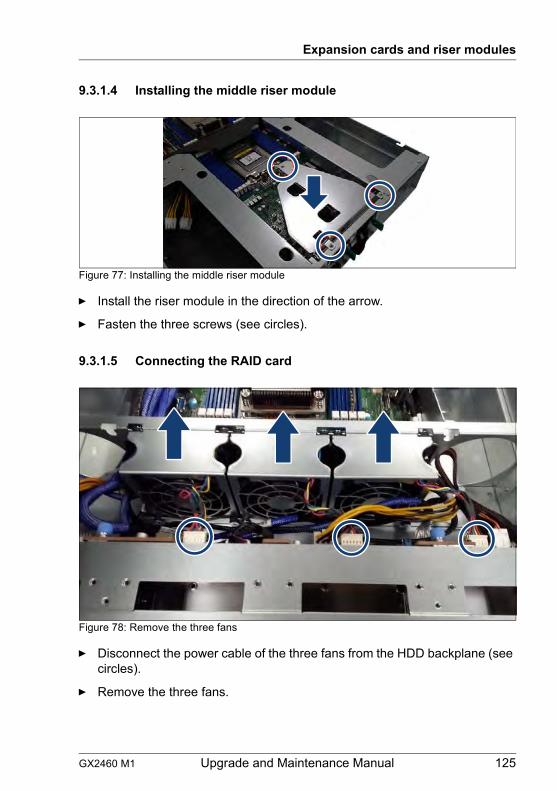
GX2460 M1 Upgrade and Maintenance Manual 125
Expansion cards and riser modules
9.3.1.4 Installing the middle riser module
Figure 77: Installing the middle riser module
Ê Install the riser module in the direction of the arrow.
Ê Fasten the three screws (see circles).
9.3.1.5 Connecting the RAID card
Figure 78: Remove the three fans
Ê Disconnect the power cable of the three fans from the HDD backplane (see circles).
Ê Remove the three fans.

126 Upgrade and Maintenance Manual GX2460 M1
Expansion cards and riser modules
Figure 79: Disconnecting the SATA cables (A)
Ê Disconnect the two SATA cables from the HDD backplane (see circles).
Figure 80: Disconnecting the SATA cables (B)
Ê Disconnect the two SATA cables from the system board (see arrows).
Ê Remove the SATA cables from the cable tie and dispose them.
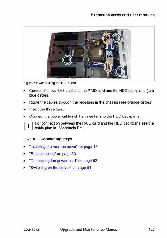
GX2460 M1 Upgrade and Maintenance Manual 127
Expansion cards and riser modules
Figure 81: Connecting the RAID card
Ê Connect the two SAS cables to the RAID card and the HDD backplane (see blue circles).
Ê Route the cables through the recesses in the chassis (see orange circles).
Ê Insert the three fans.
Ê Connect the power cables of the three fans to the HDD backplane.
I For connection between the RAID card and the HDD backplane see the cable plan in **Appendix B**.
9.3.1.6 Concluding steps
Ê "Installing the rear top cover" on page 48
Ê "Reassembling" on page 50
Ê "Connecting the power cord" on page 53
Ê "Switching on the server" on page 54
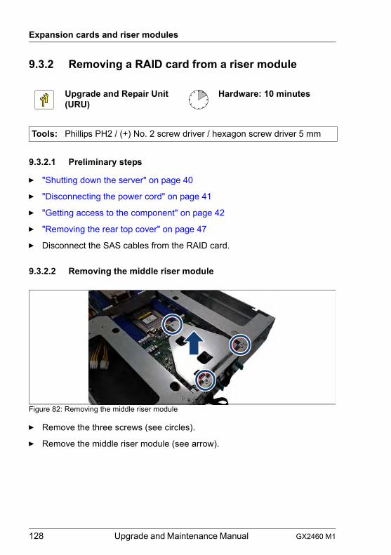
128 Upgrade and Maintenance Manual GX2460 M1
Expansion cards and riser modules
9.3.2 Removing a RAID card from a riser module
9.3.2.1 Preliminary steps
Ê "Shutting down the server" on page 40
Ê "Disconnecting the power cord" on page 41
Ê "Getting access to the component" on page 42
Ê "Removing the rear top cover" on page 47
Ê Disconnect the SAS cables from the RAID card.
9.3.2.2 Removing the middle riser module
Figure 82: Removing the middle riser module
Ê Remove the three screws (see circles).
Ê Remove the middle riser module (see arrow).
Upgrade and Repair Unit(URU)
Hardware: 10 minutes
Tools: Phillips PH2 / (+) No. 2 screw driver / hexagon screw driver 5 mm
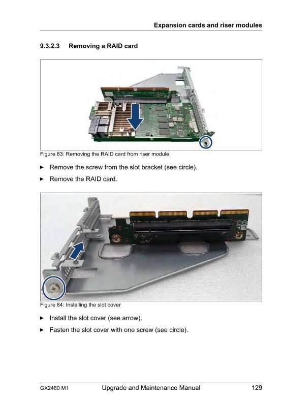
GX2460 M1 Upgrade and Maintenance Manual 129
Expansion cards and riser modules
9.3.2.3 Removing a RAID card
Figure 83: Removing the RAID card from riser module
Ê Remove the screw from the slot bracket (see circle).
Ê Remove the RAID card.
Figure 84: Installing the slot cover
Ê Install the slot cover (see arrow).
Ê Fasten the slot cover with one screw (see circle).
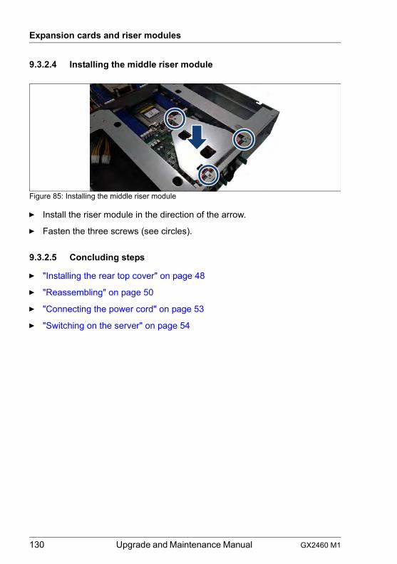
130 Upgrade and Maintenance Manual GX2460 M1
Expansion cards and riser modules
9.3.2.4 Installing the middle riser module
Figure 85: Installing the middle riser module
Ê Install the riser module in the direction of the arrow.
Ê Fasten the three screws (see circles).
9.3.2.5 Concluding steps
Ê "Installing the rear top cover" on page 48
Ê "Reassembling" on page 50
Ê "Connecting the power cord" on page 53
Ê "Switching on the server" on page 54
GX2460 M1 Upgrade and Maintenance Manual 131
Expansion cards and riser modules
9.3.3 Replacing a RAID card in a riser module
9.3.3.1 Preliminary steps
Ê "Locating the defective server" on page 39
Ê "Shutting down the server" on page 40
Ê "Disconnecting the power cord" on page 41
Ê "Removing the rear top cover" on page 47
Ê "Getting access to the component" on page 42
Ê "Removing the rear top cover" on page 47
Ê Disconnect the SAS cables from the RAID card.
9.3.3.2 Removing the defective expansion card
Ê Remove the riser module, see section "Removing the middle riser module" on page 112.
Ê Remove the defective RAID card, see section "Removing a RAID card" on page 129.
9.3.3.3 Installing the new expansion card
Ê Install the new RAID card, see section "Installing a RAID card in a riser module" on page 124.
Ê Install the riser module, see section "Installing the middle riser module" on page 114.
Ê Connect the new RAID card, see section "Connecting the RAID card" on page 125.
Upgrade and Repair Unit(URU)
Hardware: 15 minutes
Tools: Phillips PH2 / (+) No. 2 screw driver / hexagon screw driver 5 mm
132 Upgrade and Maintenance Manual GX2460 M1
Expansion cards and riser modules
9.3.3.4 Concluding steps
Ê "Installing the rear top cover" on page 48
Ê "Reassembling" on page 50
Ê "Connecting the power cord" on page 53
Ê "Switching on the server" on page 54
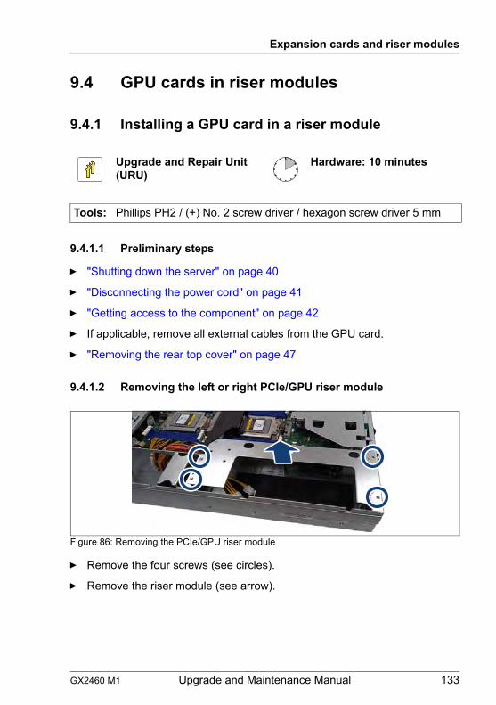
GX2460 M1 Upgrade and Maintenance Manual 133
Expansion cards and riser modules
9.4 GPU cards in riser modules
9.4.1 Installing a GPU card in a riser module
9.4.1.1 Preliminary steps
Ê "Shutting down the server" on page 40
Ê "Disconnecting the power cord" on page 41
Ê "Getting access to the component" on page 42
Ê If applicable, remove all external cables from the GPU card.
Ê "Removing the rear top cover" on page 47
9.4.1.2 Removing the left or right PCIe/GPU riser module
Figure 86: Removing the PCIe/GPU riser module
Ê Remove the four screws (see circles).
Ê Remove the riser module (see arrow).
Upgrade and Repair Unit(URU)
Hardware: 10 minutes
Tools: Phillips PH2 / (+) No. 2 screw driver / hexagon screw driver 5 mm
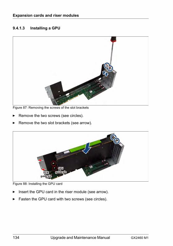
134 Upgrade and Maintenance Manual GX2460 M1
Expansion cards and riser modules
9.4.1.3 Installing a GPU
Figure 87: Removing the screws of the slot brackets
Ê Remove the two screws (see circles).
Ê Remove the two slot brackets (see arrow).
Figure 88: Installing the GPU card
Ê Insert the GPU card in the riser module (see arrow).
Ê Fasten the GPU card with two screws (see circles).
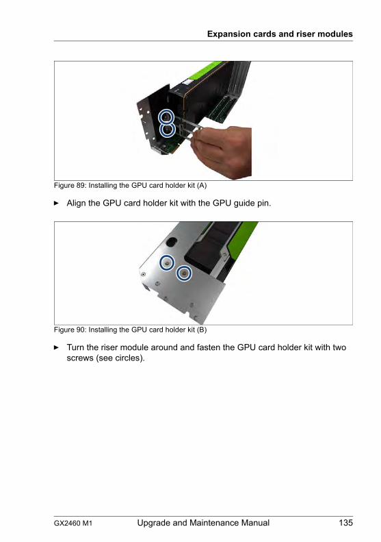
GX2460 M1 Upgrade and Maintenance Manual 135
Expansion cards and riser modules
Figure 89: Installing the GPU card holder kit (A)
Ê Align the GPU card holder kit with the GPU guide pin.
Figure 90: Installing the GPU card holder kit (B)
Ê Turn the riser module around and fasten the GPU card holder kit with two screws (see circles).
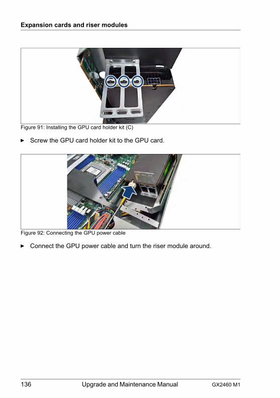
136 Upgrade and Maintenance Manual GX2460 M1
Expansion cards and riser modules
Figure 91: Installing the GPU card holder kit (C)
Ê Screw the GPU card holder kit to the GPU card.
Figure 92: Connecting the GPU power cable
Ê Connect the GPU power cable and turn the riser module around.

GX2460 M1 Upgrade and Maintenance Manual 137
Expansion cards and riser modules
9.4.1.4 Installing the left or right PCIe/GPU riser module
Figure 93: Installing the PCIe/GPU riser module
Ê Install the riser module in the direction of the arrow.
Ê Fasten the four screws (see circles).
9.4.1.5 Concluding steps
Ê "Installing the rear top cover" on page 48
Ê "Reassembling" on page 50
Ê "Connecting the power cord" on page 53
Ê "Switching on the server" on page 54
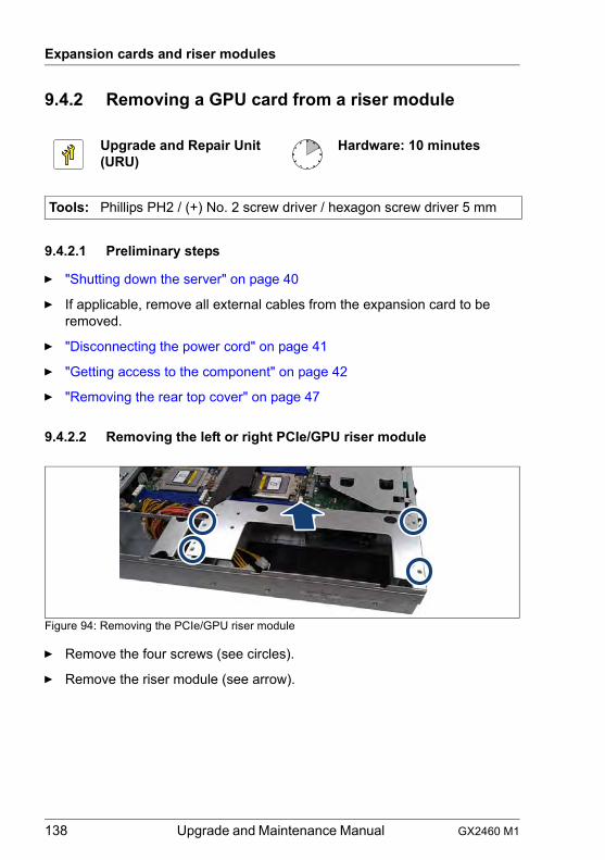
138 Upgrade and Maintenance Manual GX2460 M1
Expansion cards and riser modules
9.4.2 Removing a GPU card from a riser module
9.4.2.1 Preliminary steps
Ê "Shutting down the server" on page 40
Ê If applicable, remove all external cables from the expansion card to be removed.
Ê "Disconnecting the power cord" on page 41
Ê "Getting access to the component" on page 42
Ê "Removing the rear top cover" on page 47
9.4.2.2 Removing the left or right PCIe/GPU riser module
Figure 94: Removing the PCIe/GPU riser module
Ê Remove the four screws (see circles).
Ê Remove the riser module (see arrow).
Upgrade and Repair Unit(URU)
Hardware: 10 minutes
Tools: Phillips PH2 / (+) No. 2 screw driver / hexagon screw driver 5 mm
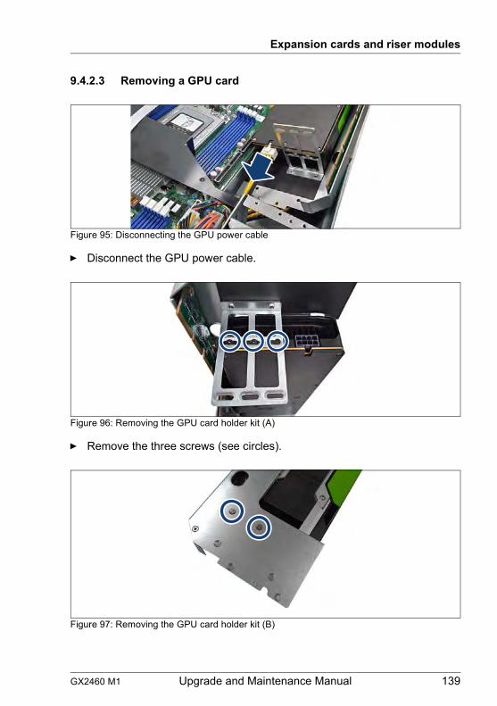
GX2460 M1 Upgrade and Maintenance Manual 139
Expansion cards and riser modules
9.4.2.3 Removing a GPU card
Figure 95: Disconnecting the GPU power cable
Ê Disconnect the GPU power cable.
Figure 96: Removing the GPU card holder kit (A)
Ê Remove the three screws (see circles).
Figure 97: Removing the GPU card holder kit (B)
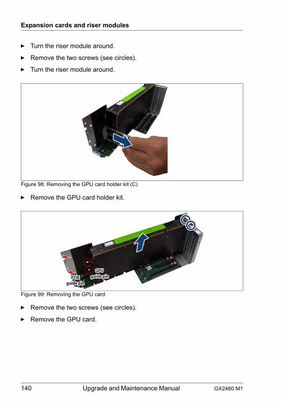
140 Upgrade and Maintenance Manual GX2460 M1
Expansion cards and riser modules
Ê Turn the riser module around.
Ê Remove the two screws (see circles).
Ê Turn the riser module around.
Figure 98: Removing the GPU card holder kit (C)
Ê Remove the GPU card holder kit.
Figure 99: Removing the GPU card
Ê Remove the two screws (see circles).
Ê Remove the GPU card.
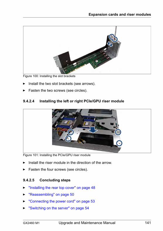
GX2460 M1 Upgrade and Maintenance Manual 141
Expansion cards and riser modules
Figure 100: Installing the slot brackets
Ê Install the two slot brackets (see arrows).
Ê Fasten the two screws (see circles).
9.4.2.4 Installing the left or right PCIe/GPU riser module
Figure 101: Installing the PCIe/GPU riser module
Ê Install the riser module in the direction of the arrow.
Ê Fasten the four screws (see circles).
9.4.2.5 Concluding steps
Ê "Installing the rear top cover" on page 48
Ê "Reassembling" on page 50
Ê "Connecting the power cord" on page 53
Ê "Switching on the server" on page 54
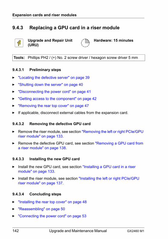
142 Upgrade and Maintenance Manual GX2460 M1
Expansion cards and riser modules
9.4.3 Replacing a GPU card in a riser module
9.4.3.1 Preliminary steps
Ê "Locating the defective server" on page 39
Ê "Shutting down the server" on page 40
Ê "Disconnecting the power cord" on page 41
Ê "Getting access to the component" on page 42
Ê "Removing the rear top cover" on page 47
Ê If applicable, disconnect external cables from the expansion card.
9.4.3.2 Removing the defective GPU card
Ê Remove the riser module, see section "Removing the left or right PCIe/GPU riser module" on page 133.
Ê Remove the defective GPU card, see section "Removing a GPU card from a riser module" on page 138.
9.4.3.3 Installing the new GPU card
Ê Install the new GPU card, see section "Installing a GPU card in a riser module" on page 133.
Ê Install the riser module, see section "Installing the left or right PCIe/GPU riser module" on page 137.
9.4.3.4 Concluding steps
Ê "Installing the rear top cover" on page 48
Ê "Reassembling" on page 50
Ê "Connecting the power cord" on page 53
Upgrade and Repair Unit(URU)
Hardware: 15 minutes
Tools: Phillips PH2 / (+) No. 2 screw driver / hexagon screw driver 5 mm
GX2460 M1 Upgrade and Maintenance Manual 143
Expansion cards and riser modules
Ê "Switching on the server" on page 54
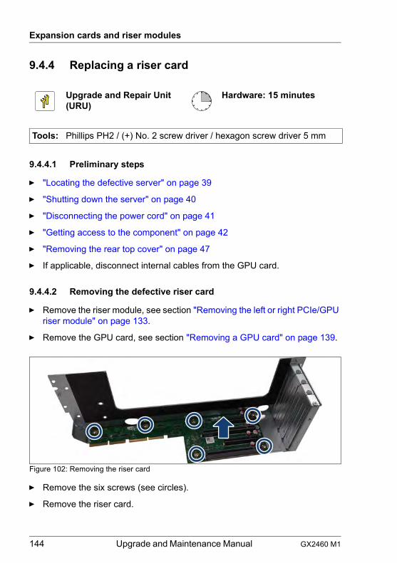
144 Upgrade and Maintenance Manual GX2460 M1
Expansion cards and riser modules
9.4.4 Replacing a riser card
9.4.4.1 Preliminary steps
Ê "Locating the defective server" on page 39
Ê "Shutting down the server" on page 40
Ê "Disconnecting the power cord" on page 41
Ê "Getting access to the component" on page 42
Ê "Removing the rear top cover" on page 47
Ê If applicable, disconnect internal cables from the GPU card.
9.4.4.2 Removing the defective riser card
Ê Remove the riser module, see section "Removing the left or right PCIe/GPU riser module" on page 133.
Ê Remove the GPU card, see section "Removing a GPU card" on page 139.
Figure 102: Removing the riser card
Ê Remove the six screws (see circles).
Ê Remove the riser card.
Upgrade and Repair Unit(URU)
Hardware: 15 minutes
Tools: Phillips PH2 / (+) No. 2 screw driver / hexagon screw driver 5 mm
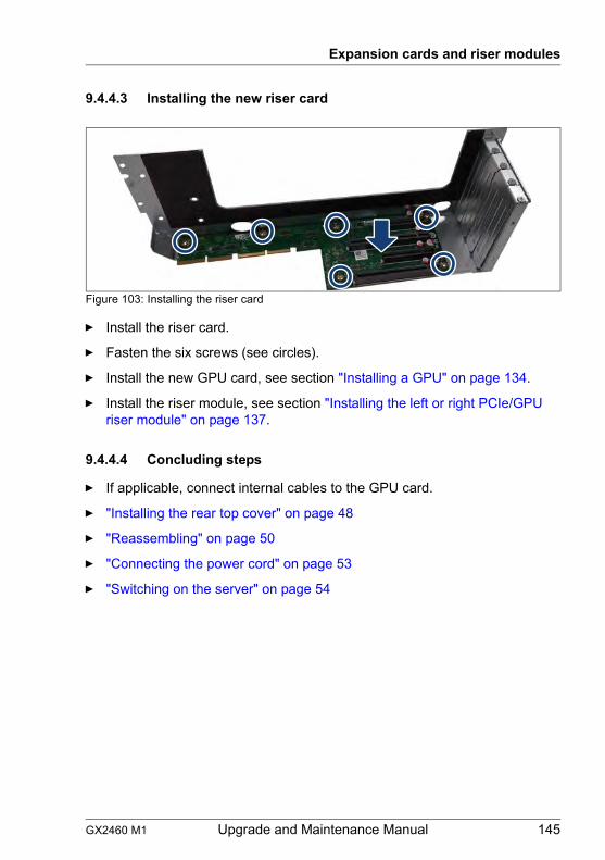
GX2460 M1 Upgrade and Maintenance Manual 145
Expansion cards and riser modules
9.4.4.3 Installing the new riser card
Figure 103: Installing the riser card
Ê Install the riser card.
Ê Fasten the six screws (see circles).
Ê Install the new GPU card, see section "Installing a GPU" on page 134.
Ê Install the riser module, see section "Installing the left or right PCIe/GPU riser module" on page 137.
9.4.4.4 Concluding steps
Ê If applicable, connect internal cables to the GPU card.
Ê "Installing the rear top cover" on page 48
Ê "Reassembling" on page 50
Ê "Connecting the power cord" on page 53
Ê "Switching on the server" on page 54
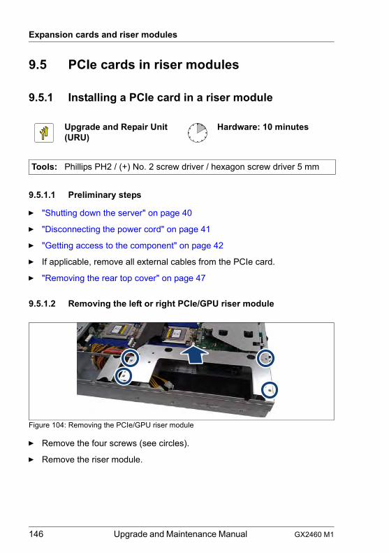
146 Upgrade and Maintenance Manual GX2460 M1
Expansion cards and riser modules
9.5 PCIe cards in riser modules
9.5.1 Installing a PCIe card in a riser module
9.5.1.1 Preliminary steps
Ê "Shutting down the server" on page 40
Ê "Disconnecting the power cord" on page 41
Ê "Getting access to the component" on page 42
Ê If applicable, remove all external cables from the PCIe card.
Ê "Removing the rear top cover" on page 47
9.5.1.2 Removing the left or right PCIe/GPU riser module
Figure 104: Removing the PCIe/GPU riser module
Ê Remove the four screws (see circles).
Ê Remove the riser module.
Upgrade and Repair Unit(URU)
Hardware: 10 minutes
Tools: Phillips PH2 / (+) No. 2 screw driver / hexagon screw driver 5 mm
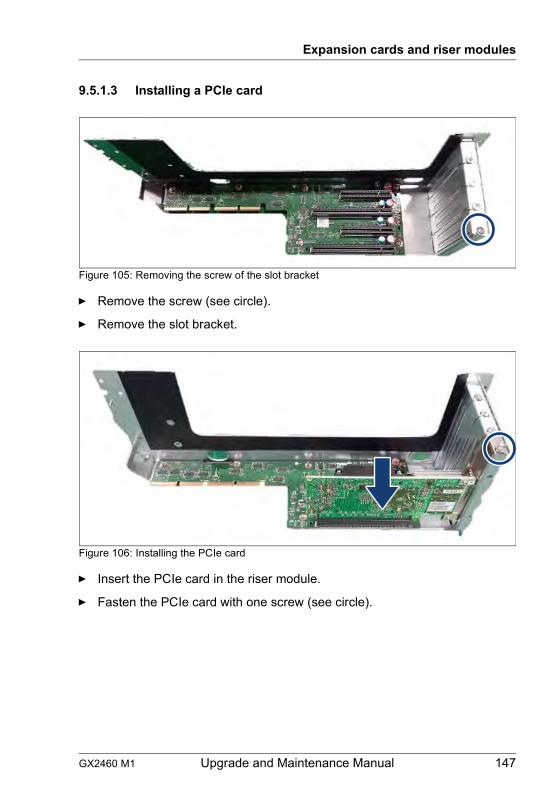
GX2460 M1 Upgrade and Maintenance Manual 147
Expansion cards and riser modules
9.5.1.3 Installing a PCIe card
Figure 105: Removing the screw of the slot bracket
Ê Remove the screw (see circle).
Ê Remove the slot bracket.
Figure 106: Installing the PCIe card
Ê Insert the PCIe card in the riser module.
Ê Fasten the PCIe card with one screw (see circle).
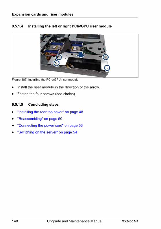
148 Upgrade and Maintenance Manual GX2460 M1
Expansion cards and riser modules
9.5.1.4 Installing the left or right PCIe/GPU riser module
Figure 107: Installing the PCIe/GPU riser module
Ê Install the riser module in the direction of the arrow.
Ê Fasten the four screws (see circles).
9.5.1.5 Concluding steps
Ê "Installing the rear top cover" on page 48
Ê "Reassembling" on page 50
Ê "Connecting the power cord" on page 53
Ê "Switching on the server" on page 54
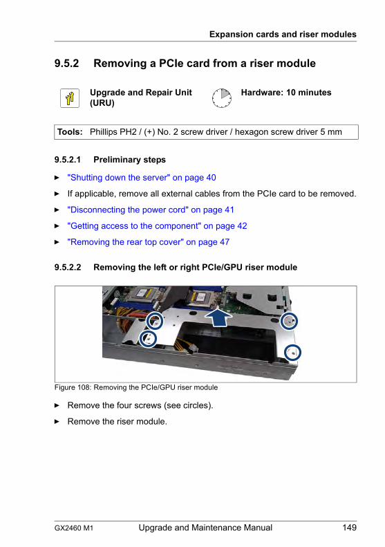
GX2460 M1 Upgrade and Maintenance Manual 149
Expansion cards and riser modules
9.5.2 Removing a PCIe card from a riser module
9.5.2.1 Preliminary steps
Ê "Shutting down the server" on page 40
Ê If applicable, remove all external cables from the PCIe card to be removed.
Ê "Disconnecting the power cord" on page 41
Ê "Getting access to the component" on page 42
Ê "Removing the rear top cover" on page 47
9.5.2.2 Removing the left or right PCIe/GPU riser module
Figure 108: Removing the PCIe/GPU riser module
Ê Remove the four screws (see circles).
Ê Remove the riser module.
Upgrade and Repair Unit(URU)
Hardware: 10 minutes
Tools: Phillips PH2 / (+) No. 2 screw driver / hexagon screw driver 5 mm
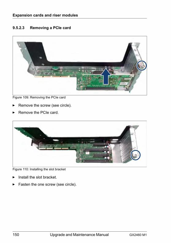
150 Upgrade and Maintenance Manual GX2460 M1
Expansion cards and riser modules
9.5.2.3 Removing a PCIe card
Figure 109: Removing the PCIe card
Ê Remove the screw (see circle).
Ê Remove the PCIe card.
Figure 110: Installing the slot bracket
Ê Install the slot bracket.
Ê Fasten the one screw (see circle).
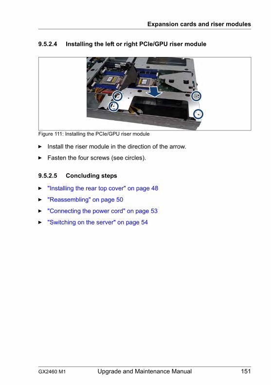
GX2460 M1 Upgrade and Maintenance Manual 151
Expansion cards and riser modules
9.5.2.4 Installing the left or right PCIe/GPU riser module
Figure 111: Installing the PCIe/GPU riser module
Ê Install the riser module in the direction of the arrow.
Ê Fasten the four screws (see circles).
9.5.2.5 Concluding steps
Ê "Installing the rear top cover" on page 48
Ê "Reassembling" on page 50
Ê "Connecting the power cord" on page 53
Ê "Switching on the server" on page 54
152 Upgrade and Maintenance Manual GX2460 M1
Expansion cards and riser modules
9.5.3 Replacing a PCIe card in a riser module
9.5.3.1 Preliminary steps
Ê "Locating the defective server" on page 39
Ê "Shutting down the server" on page 40
Ê "Disconnecting the power cord" on page 41
Ê "Getting access to the component" on page 42
Ê "Removing the rear top cover" on page 47
Ê If applicable, disconnect external cables from the PCIe card.
9.5.3.2 Removing the defective PCIe card
Ê Remove the riser module, see section "Removing the left or right PCIe/GPU riser module" on page 133.
Ê Remove the defective PCIe card, see section "Removing a PCIe card" on page 150.
9.5.3.3 Installing the new PCIe card
Ê Install the new PCIe card, see section "Installing a PCIe card" on page 147.
Ê Install the riser module, see section "Installing the left or right PCIe/GPU riser module" on page 137.
9.5.3.4 Concluding steps
Ê "Installing the rear top cover" on page 48
Ê "Reassembling" on page 50
Ê "Connecting the power cord" on page 53
Upgrade and Repair Unit(URU)
Hardware: 15 minutes
Tools: Phillips PH2 / (+) No. 2 screw driver / hexagon screw driver 5 mm

GX2460 M1 Upgrade and Maintenance Manual 153
Expansion cards and riser modules
Ê "Switching on the server" on page 54
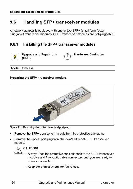
154 Upgrade and Maintenance Manual GX2460 M1
Expansion cards and riser modules
9.6 Handling SFP+ transceiver modules
A network adapter is equipped with one or two SFP+ (small form-factor pluggable) transceiver modules. SFP+ transceiver modules are hot-pluggable.
9.6.1 Installing the SFP+ transceiver modules
Preparing the SFP+ transceiver module
Figure 112: Removing the protective optical port plug
Ê Remove the SFP+ transceiver module from its protective packaging.
Ê Remove the optical port plug from the new/additional SFP+ transceiver module.
V CAUTION!
– Always keep the protective caps attached to the SFP+ transceiver modules and fiber-optic cable connectors until you are ready to make a connection.
– Keep the protective cap for future use.
Upgrade and Repair Unit(URU)
Hardware: 5 minutes
Tools: tool-less
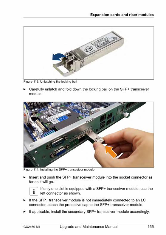
GX2460 M1 Upgrade and Maintenance Manual 155
Expansion cards and riser modules
Figure 113: Unlatching the locking bail
Ê Carefully unlatch and fold down the locking bail on the SFP+ transceiver module.
Figure 114: Installing the SFP+ transceiver module
Ê Insert and push the SFP+ transceiver module into the socket connector as far as it will go.
I If only one slot is equipped with a SFP+ transceiver module, use the left connector as shown.
Ê If the SFP+ transceiver module is not immediately connected to an LC connector, attach the protective cap to the SFP+ transceiver module.
Ê If applicable, install the secondary SFP+ transceiver module accordingly.
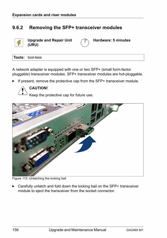
156 Upgrade and Maintenance Manual GX2460 M1
Expansion cards and riser modules
9.6.2 Removing the SFP+ transceiver modules
A network adapter is equipped with one or two SFP+ (small form-factor pluggable) transceiver modules. SFP+ transceiver modules are hot-pluggable.
Ê If present, remove the protective cap from the SFP+ transceiver module.
V CAUTION!
Keep the protective cap for future use.
Figure 115: Unlatching the locking bail
Ê Carefully unlatch and fold down the locking bail on the SFP+ transceiver module to eject the transceiver from the socket connector.
Upgrade and Repair Unit(URU)
Hardware: 5 minutes
Tools: tool-less
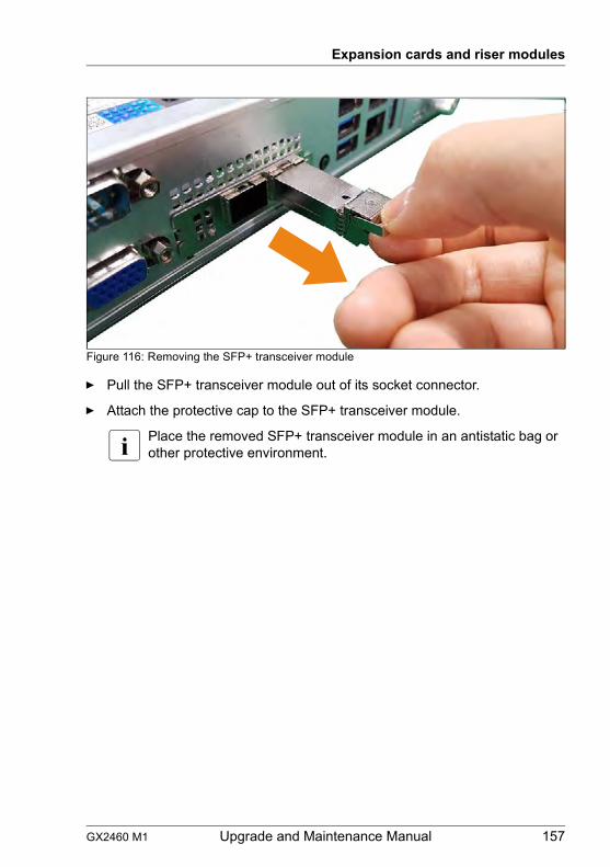
GX2460 M1 Upgrade and Maintenance Manual 157
Expansion cards and riser modules
Figure 116: Removing the SFP+ transceiver module
Ê Pull the SFP+ transceiver module out of its socket connector.
Ê Attach the protective cap to the SFP+ transceiver module.
I Place the removed SFP+ transceiver module in an antistatic bag or other protective environment.
158 Upgrade and Maintenance Manual GX2460 M1
Expansion cards and riser modules
GX2460 M1 Upgrade and Maintenance Manual 159
10 Main memorySafety notes
V CAUTION!
● Before removing several memory modules, make sure that all memory modules can be reinstalled into their original slots. Otherwise, data may be lost.
● Do not install unsupported third party memory modules. For more information on supported memory modules, see section "Basic information" on page 160. Doing so may cause electric shock, a fire, or failures.
● Memory modules remain hot after shutdown. Wait for components to cool down before installing or removing memory modules to prevent burns.
● Do not insert and remove memory modules repeatedly. Doing so may cause failures.
● If the memory module has not been correctly inserted, it may cause a fire. Insert the memory module with attention.
● Pressing out the securing clips on the memory module connector will eject the installed memory module. To prevent damage and injuries eject memory modules carefully without applying excessive force.
● For more information, see chapter "Important information" on page 27.
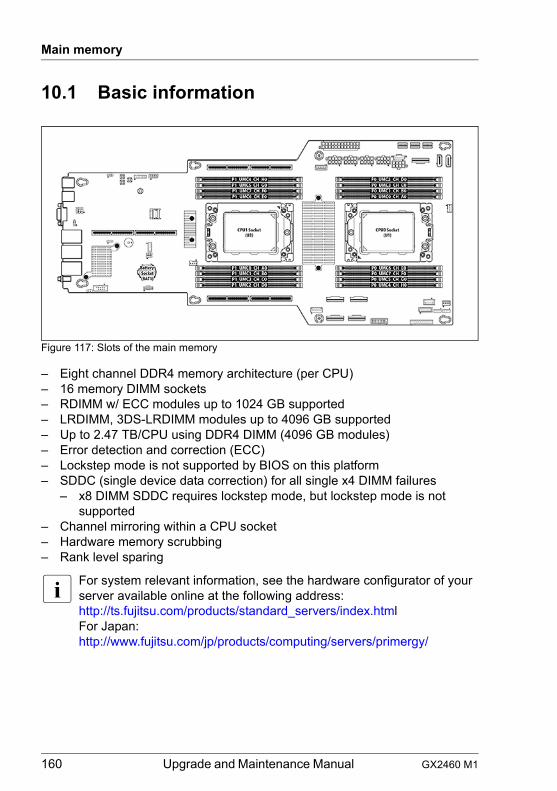
160 Upgrade and Maintenance Manual GX2460 M1
Main memory
10.1 Basic information
Figure 117: Slots of the main memory
– Eight channel DDR4 memory architecture (per CPU)– 16 memory DIMM sockets– RDIMM w/ ECC modules up to 1024 GB supported– LRDIMM, 3DS-LRDIMM modules up to 4096 GB supported– Up to 2.47 TB/CPU using DDR4 DIMM (4096 GB modules)– Error detection and correction (ECC)– Lockstep mode is not supported by BIOS on this platform– SDDC (single device data correction) for all single x4 DIMM failures
– x8 DIMM SDDC requires lockstep mode, but lockstep mode is not supported
– Channel mirroring within a CPU socket– Hardware memory scrubbing– Rank level sparing
I For system relevant information, see the hardware configurator of your server available online at the following address:http://ts.fujitsu.com/products/standard_servers/index.htmlFor Japan:http://www.fujitsu.com/jp/products/computing/servers/primergy/
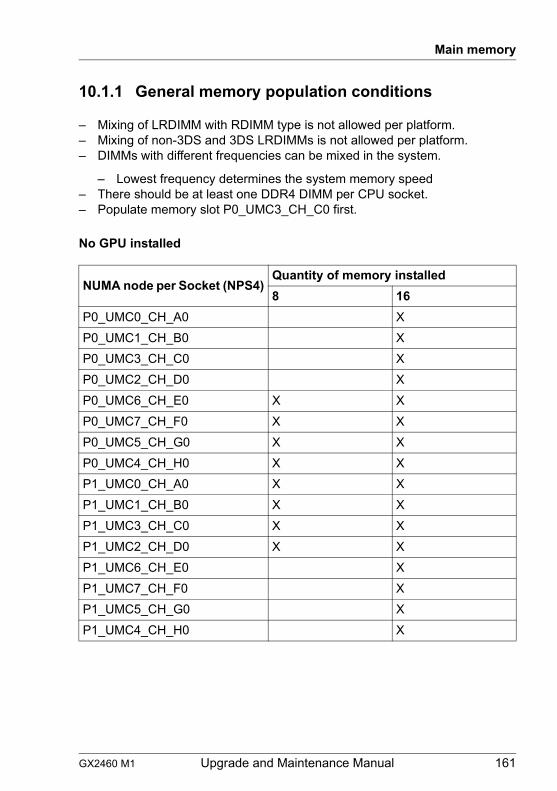
GX2460 M1 Upgrade and Maintenance Manual 161
Main memory
10.1.1 General memory population conditions
– Mixing of LRDIMM with RDIMM type is not allowed per platform.– Mixing of non-3DS and 3DS LRDIMMs is not allowed per platform.– DIMMs with different frequencies can be mixed in the system.
– Lowest frequency determines the system memory speed– There should be at least one DDR4 DIMM per CPU socket.– Populate memory slot P0_UMC3_CH_C0 first.
No GPU installed
NUMA node per Socket (NPS4)Quantity of memory installed8 16
P0_UMC0_CH_A0 XP0_UMC1_CH_B0 XP0_UMC3_CH_C0 XP0_UMC2_CH_D0 XP0_UMC6_CH_E0 X XP0_UMC7_CH_F0 X XP0_UMC5_CH_G0 X XP0_UMC4_CH_H0 X XP1_UMC0_CH_A0 X XP1_UMC1_CH_B0 X XP1_UMC3_CH_C0 X XP1_UMC2_CH_D0 X XP1_UMC6_CH_E0 XP1_UMC7_CH_F0 XP1_UMC5_CH_G0 XP1_UMC4_CH_H0 X
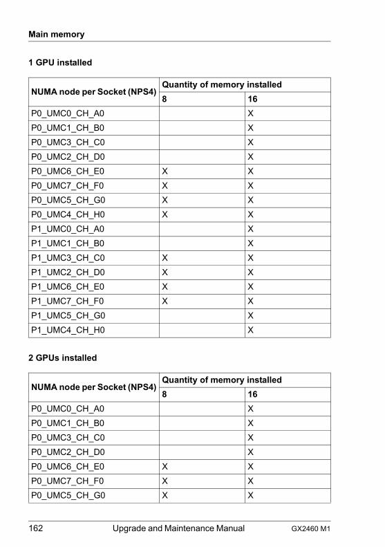
162 Upgrade and Maintenance Manual GX2460 M1
Main memory
1 GPU installed
2 GPUs installed
NUMA node per Socket (NPS4)Quantity of memory installed8 16
P0_UMC0_CH_A0 XP0_UMC1_CH_B0 XP0_UMC3_CH_C0 XP0_UMC2_CH_D0 XP0_UMC6_CH_E0 X XP0_UMC7_CH_F0 X XP0_UMC5_CH_G0 X XP0_UMC4_CH_H0 X XP1_UMC0_CH_A0 XP1_UMC1_CH_B0 XP1_UMC3_CH_C0 X XP1_UMC2_CH_D0 X XP1_UMC6_CH_E0 X XP1_UMC7_CH_F0 X XP1_UMC5_CH_G0 XP1_UMC4_CH_H0 X
NUMA node per Socket (NPS4)Quantity of memory installed8 16
P0_UMC0_CH_A0 XP0_UMC1_CH_B0 XP0_UMC3_CH_C0 XP0_UMC2_CH_D0 XP0_UMC6_CH_E0 X XP0_UMC7_CH_F0 X XP0_UMC5_CH_G0 X X

GX2460 M1 Upgrade and Maintenance Manual 163
Main memory
3 GPUs installed
P0_UMC4_CH_H0 X XP1_UMC0_CH_A0 X XP1_UMC1_CH_B0 X XP1_UMC3_CH_C0 X XP1_UMC2_CH_D0 X XP1_UMC6_CH_E0 XP1_UMC7_CH_F0 XP1_UMC5_CH_G0 XP1_UMC4_CH_H0 X
NUMA node per Socket (NPS4)Quantity of memory installed8 16
P0_UMC0_CH_A0 XP0_UMC1_CH_B0 XP0_UMC3_CH_C0 XP0_UMC2_CH_D0 XP0_UMC6_CH_E0 X XP0_UMC7_CH_F0 X XP0_UMC5_CH_G0 X XP0_UMC4_CH_H0 X XP1_UMC0_CH_A0 XP1_UMC1_CH_B0 XP1_UMC3_CH_C0 X XP1_UMC2_CH_D0 X XP1_UMC6_CH_E0 X XP1_UMC7_CH_F0 X XP1_UMC5_CH_G0 X
NUMA node per Socket (NPS4)Quantity of memory installed8 16
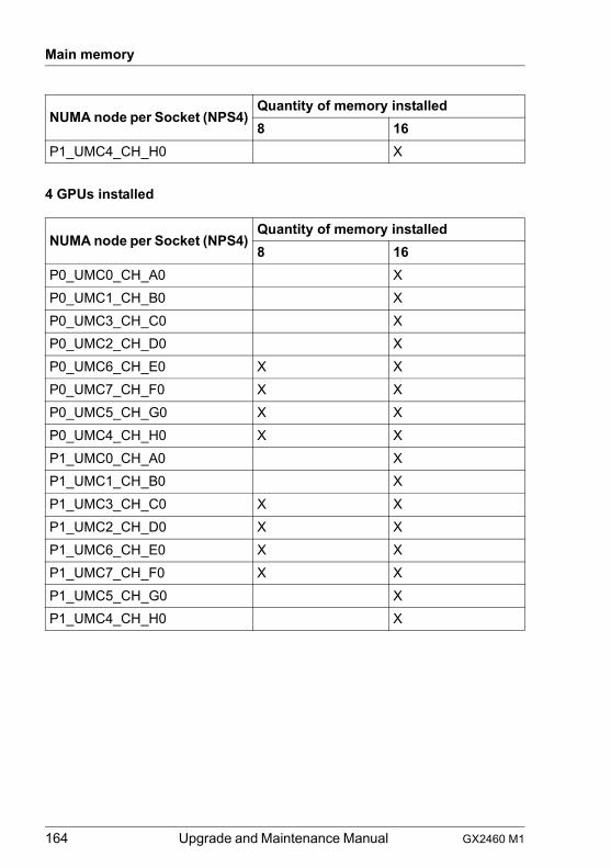
164 Upgrade and Maintenance Manual GX2460 M1
Main memory
4 GPUs installed
P1_UMC4_CH_H0 X
NUMA node per Socket (NPS4)Quantity of memory installed8 16
P0_UMC0_CH_A0 XP0_UMC1_CH_B0 XP0_UMC3_CH_C0 XP0_UMC2_CH_D0 XP0_UMC6_CH_E0 X XP0_UMC7_CH_F0 X XP0_UMC5_CH_G0 X XP0_UMC4_CH_H0 X XP1_UMC0_CH_A0 XP1_UMC1_CH_B0 XP1_UMC3_CH_C0 X XP1_UMC2_CH_D0 X XP1_UMC6_CH_E0 X XP1_UMC7_CH_F0 X XP1_UMC5_CH_G0 XP1_UMC4_CH_H0 X
NUMA node per Socket (NPS4)Quantity of memory installed8 16
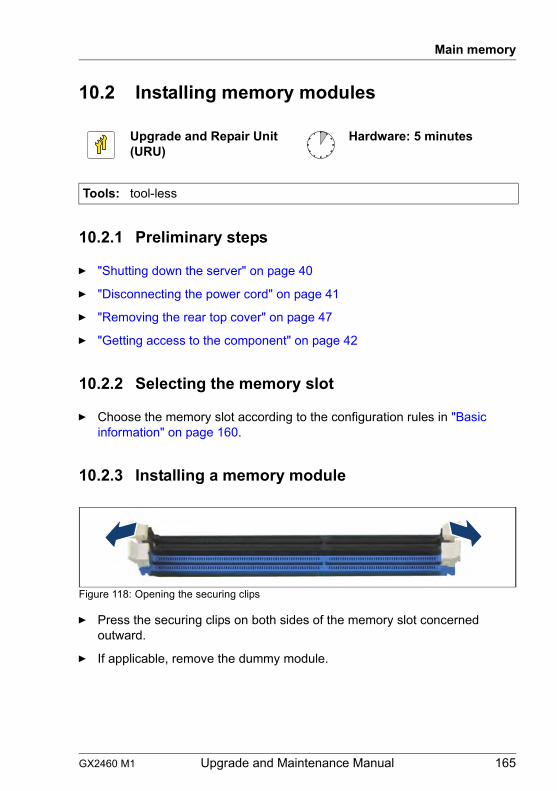
GX2460 M1 Upgrade and Maintenance Manual 165
Main memory
10.2 Installing memory modules
10.2.1 Preliminary steps
Ê "Shutting down the server" on page 40
Ê "Disconnecting the power cord" on page 41
Ê "Removing the rear top cover" on page 47
Ê "Getting access to the component" on page 42
10.2.2 Selecting the memory slot
Ê Choose the memory slot according to the configuration rules in "Basic information" on page 160.
10.2.3 Installing a memory module
Figure 118: Opening the securing clips
Ê Press the securing clips on both sides of the memory slot concerned outward.
Ê If applicable, remove the dummy module.
Upgrade and Repair Unit(URU)
Hardware: 5 minutes
Tools: tool-less
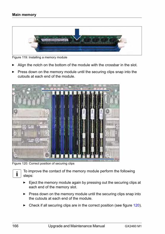
166 Upgrade and Maintenance Manual GX2460 M1
Main memory
Figure 119: Installing a memory module
Ê Align the notch on the bottom of the module with the crossbar in the slot.
Ê Press down on the memory module until the securing clips snap into the cutouts at each end of the module.
Figure 120: Correct position of securing clips
I To improve the contact of the memory module perform the following steps:
Ê Eject the memory module again by pressing out the securing clips at each end of the memory slot.
Ê Press down on the memory module until the securing clips snap into the cutouts at each end of the module.
Ê Check if all securing clips are in the correct position (see figure 120).
GX2460 M1 Upgrade and Maintenance Manual 167
Main memory
10.2.4 Concluding steps
Ê "Installing the front top cover" on page 49
Ê "Reassembling" on page 50
Ê "Connecting the power cord" on page 53
Ê "Switching on the server" on page 54
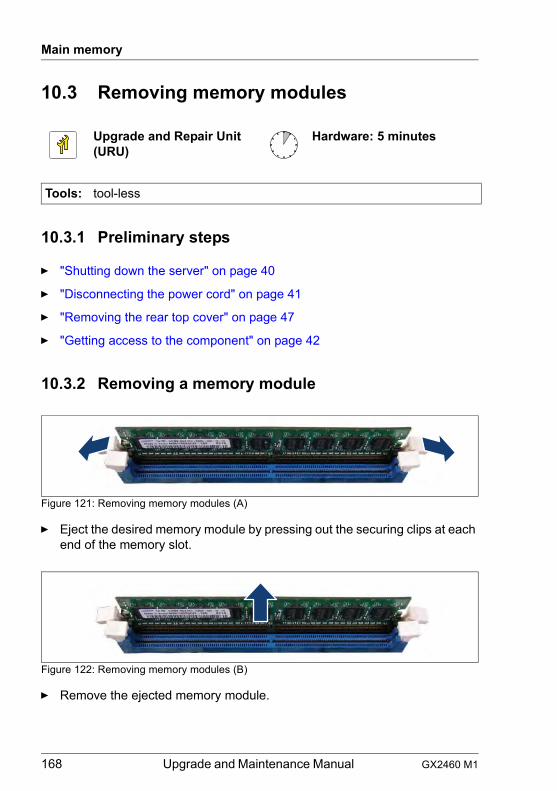
168 Upgrade and Maintenance Manual GX2460 M1
Main memory
10.3 Removing memory modules
10.3.1 Preliminary steps
Ê "Shutting down the server" on page 40
Ê "Disconnecting the power cord" on page 41
Ê "Removing the rear top cover" on page 47
Ê "Getting access to the component" on page 42
10.3.2 Removing a memory module
Figure 121: Removing memory modules (A)
Ê Eject the desired memory module by pressing out the securing clips at each end of the memory slot.
Figure 122: Removing memory modules (B)
Ê Remove the ejected memory module.
Upgrade and Repair Unit(URU)
Hardware: 5 minutes
Tools: tool-less

GX2460 M1 Upgrade and Maintenance Manual 169
Main memory
10.3.3 Concluding steps
Ê "Installing the front top cover" on page 49
Ê "Reassembling" on page 50
Ê "Connecting the power cord" on page 53
Ê "Switching on the server" on page 54
170 Upgrade and Maintenance Manual GX2460 M1
Main memory
10.4 Replacing memory modules
10.4.1 Preliminary steps
Ê "Locating the defective server" on page 39
Ê "Shutting down the server" on page 40
Ê "Disconnecting the power cord" on page 41
Ê "Removing the rear top cover" on page 47
Ê "Locating the defective component" on page 39
10.4.2 Removing a defective memory module
Ê Remove the memory module, see section "Removing a memory module" on page 168.
10.4.3 Installing a new memory module
Ê Install the memory module, see section "Installing a memory module" on page 165.
10.4.4 Concluding steps
Ê "Installing the front top cover" on page 49
Ê "Reassembling" on page 50
Ê "Connecting the power cord" on page 53
Ê "Switching on the server" on page 54
Upgrade and Repair Unit(URU)
Hardware: 10 minutes
Tools: tool-less
GX2460 M1 Upgrade and Maintenance Manual 171
11 Processor (CPU)Safety notes
V CAUTION!
● Do not install unsupported CPUs. For more information on supported CPUs, see section "Basic information" on page 172.
● Circuit boards and soldered parts of internal options are exposed and can be damaged by static electricity. Always discharge static build-up (e.g. by touching a grounded object) before handling electrostatic-sensitive devices (ESDs).
● Do not touch the circuitry on boards or soldered parts. Hold circuit boards by their metallic areas or edges.
● When removing or installing CPUs, be careful not to touch or bend the spring contacts on the CPU sockets.
● Never touch the underside of the CPUs. Even minor soiling such as grease from the skin can impair the CPU’s operation or destroy the CPUs.
● For more information, see chapter "Important information" on page 27.
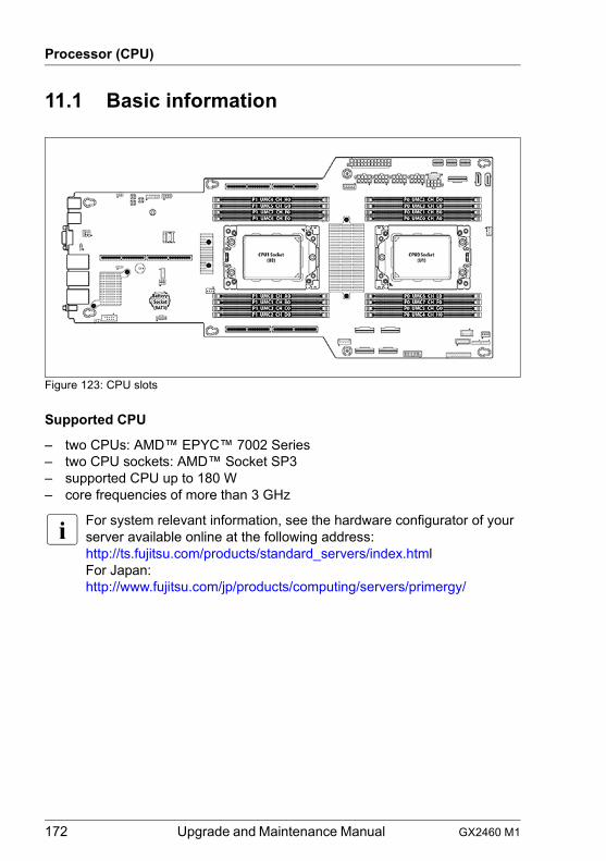
172 Upgrade and Maintenance Manual GX2460 M1
Processor (CPU)
11.1 Basic information
Figure 123: CPU slots
Supported CPU
– two CPUs: AMD™ EPYC™ 7002 Series– two CPU sockets: AMD™ Socket SP3– supported CPU up to 180 W– core frequencies of more than 3 GHz
I For system relevant information, see the hardware configurator of your server available online at the following address:http://ts.fujitsu.com/products/standard_servers/index.htmlFor Japan:http://www.fujitsu.com/jp/products/computing/servers/primergy/
GX2460 M1 Upgrade and Maintenance Manual 173
Processor (CPU)
11.2 Replacing a CPU or heat sink
V CAUTION!
CPUs are modules, which are extremely sensitive to electrostatic discharges and therefore must always be handled with care. After a CPU has been removed from its protective sleeve or from its socket, place it with its smooth side down on a non-conducting, antistatic surface. Never push a CPU over a surface.
11.2.1 Preliminary steps
Ê "Locating the defective server" on page 39
Ê "Shutting down the server" on page 40
Ê "Disconnecting the power cord" on page 41
Ê "Getting access to the component" on page 42
Ê "Removing the rear top cover" on page 47
Ê "Removing the air duct" on page 55
Field Replaceable Unit(FRU)
Hardware: 20 minutes
Tools: T20 Torx screw driver
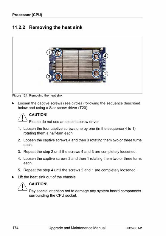
174 Upgrade and Maintenance Manual GX2460 M1
Processor (CPU)
11.2.2 Removing the heat sink
Figure 124: Removing the heat sink
Ê Loosen the captive screws (see circles) following the sequence described below and using a Star screw driver (T20):
V CAUTION!
Please do not use an electric screw driver.
1. Loosen the four captive screws one by one (in the sequence 4 to 1) rotating them a half-turn each.
2. Loosen the captive screws 4 and then 3 rotating them two or three turns each.
3. Repeat the step 2 until the screws 4 and 3 are completely loosened.
4. Loosen the captive screws 2 and then 1 rotating them two or three turns each.
5. Repeat the step 4 until the screws 2 and 1 are completely loosened.
Ê Lift the heat sink out of the chassis.
V CAUTION!
Pay special attention not to damage any system board components surrounding the CPU socket.
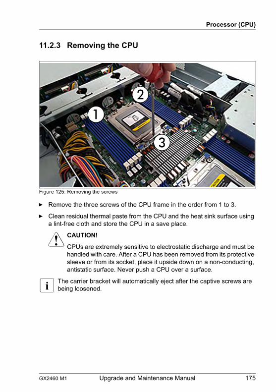
GX2460 M1 Upgrade and Maintenance Manual 175
Processor (CPU)
11.2.3 Removing the CPU
Figure 125: Removing the screws
Ê Remove the three screws of the CPU frame in the order from 1 to 3.
Ê Clean residual thermal paste from the CPU and the heat sink surface using a lint-free cloth and store the CPU in a save place.
V CAUTION!
CPUs are extremely sensitive to electrostatic discharge and must be handled with care. After a CPU has been removed from its protective sleeve or from its socket, place it upside down on a non-conducting, antistatic surface. Never push a CPU over a surface.
I The carrier bracket will automatically eject after the captive screws are being loosened.
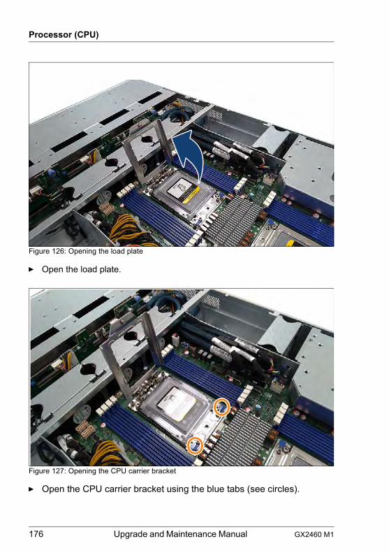
176 Upgrade and Maintenance Manual GX2460 M1
Processor (CPU)
Figure 126: Opening the load plate
Ê Open the load plate.
Figure 127: Opening the CPU carrier bracket
Ê Open the CPU carrier bracket using the blue tabs (see circles).
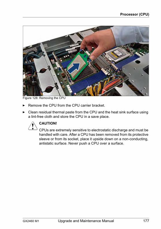
GX2460 M1 Upgrade and Maintenance Manual 177
Processor (CPU)
Figure 128: Removing the CPU
Ê Remove the CPU from the CPU carrier bracket.
Ê Clean residual thermal paste from the CPU and the heat sink surface using a lint-free cloth and store the CPU in a save place.
V CAUTION!
CPUs are extremely sensitive to electrostatic discharge and must be handled with care. After a CPU has been removed from its protective sleeve or from its socket, place it upside down on a non-conducting, antistatic surface. Never push a CPU over a surface.
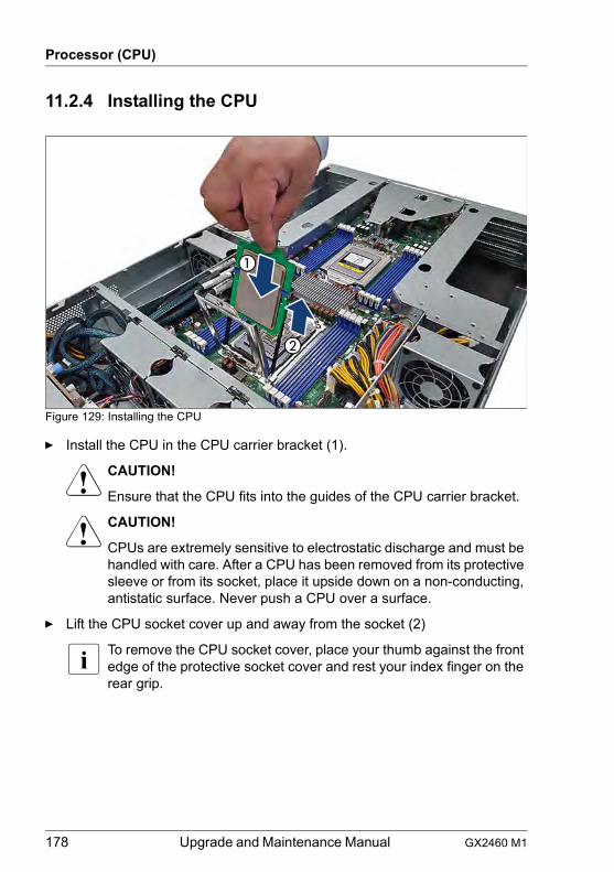
178 Upgrade and Maintenance Manual GX2460 M1
Processor (CPU)
11.2.4 Installing the CPU
Figure 129: Installing the CPU
Ê Install the CPU in the CPU carrier bracket (1).
V CAUTION!
Ensure that the CPU fits into the guides of the CPU carrier bracket.
V CAUTION!
CPUs are extremely sensitive to electrostatic discharge and must be handled with care. After a CPU has been removed from its protective sleeve or from its socket, place it upside down on a non-conducting, antistatic surface. Never push a CPU over a surface.
Ê Lift the CPU socket cover up and away from the socket (2)
I To remove the CPU socket cover, place your thumb against the front edge of the protective socket cover and rest your index finger on the rear grip.
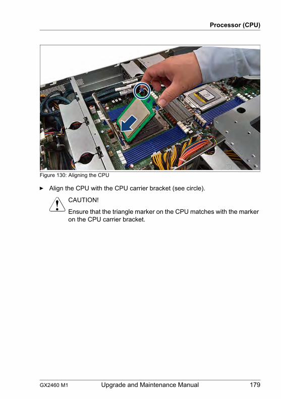
GX2460 M1 Upgrade and Maintenance Manual 179
Processor (CPU)
Figure 130: Aligning the CPU
Ê Align the CPU with the CPU carrier bracket (see circle).
V CAUTION!
Ensure that the triangle marker on the CPU matches with the marker on the CPU carrier bracket.
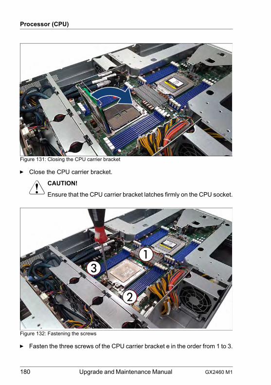
180 Upgrade and Maintenance Manual GX2460 M1
Processor (CPU)
Figure 131: Closing the CPU carrier bracket
Ê Close the CPU carrier bracket.
V CAUTION!
Ensure that the CPU carrier bracket latches firmly on the CPU socket.
Figure 132: Fastening the screws
Ê Fasten the three screws of the CPU carrier bracket e in the order from 1 to 3.
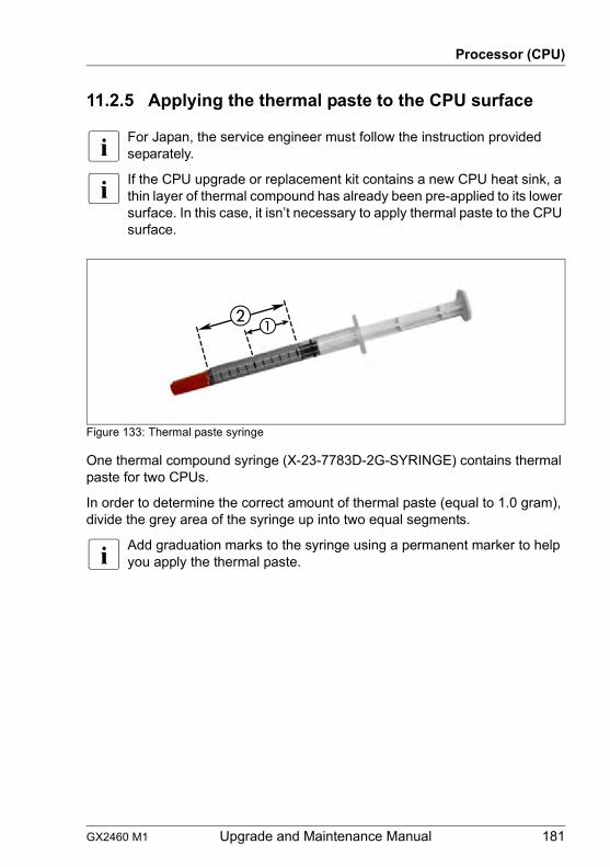
GX2460 M1 Upgrade and Maintenance Manual 181
Processor (CPU)
11.2.5 Applying the thermal paste to the CPU surface
I For Japan, the service engineer must follow the instruction provided separately.
I If the CPU upgrade or replacement kit contains a new CPU heat sink, a thin layer of thermal compound has already been pre-applied to its lower surface. In this case, it isn’t necessary to apply thermal paste to the CPU surface.
Figure 133: Thermal paste syringe
One thermal compound syringe (X-23-7783D-2G-SYRINGE) contains thermal paste for two CPUs.
In order to determine the correct amount of thermal paste (equal to 1.0 gram), divide the grey area of the syringe up into two equal segments.
I Add graduation marks to the syringe using a permanent marker to help you apply the thermal paste.
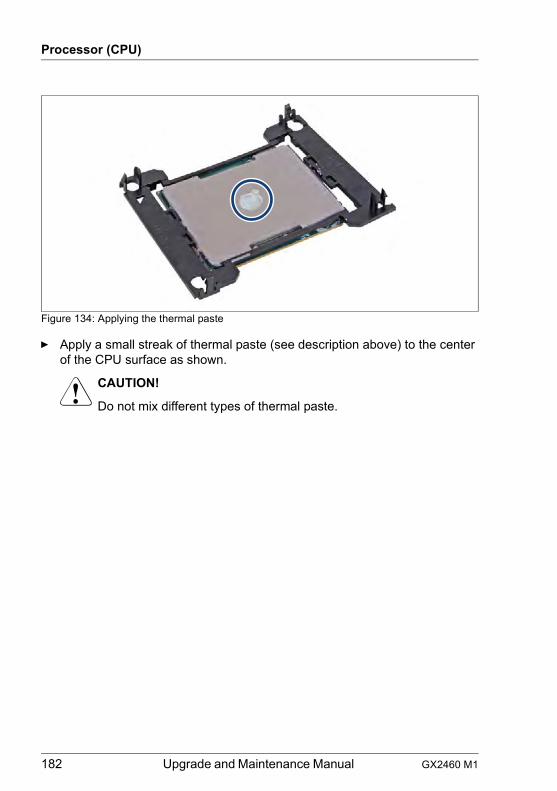
182 Upgrade and Maintenance Manual GX2460 M1
Processor (CPU)
Figure 134: Applying the thermal paste
Ê Apply a small streak of thermal paste (see description above) to the center of the CPU surface as shown.
V CAUTION!
Do not mix different types of thermal paste.
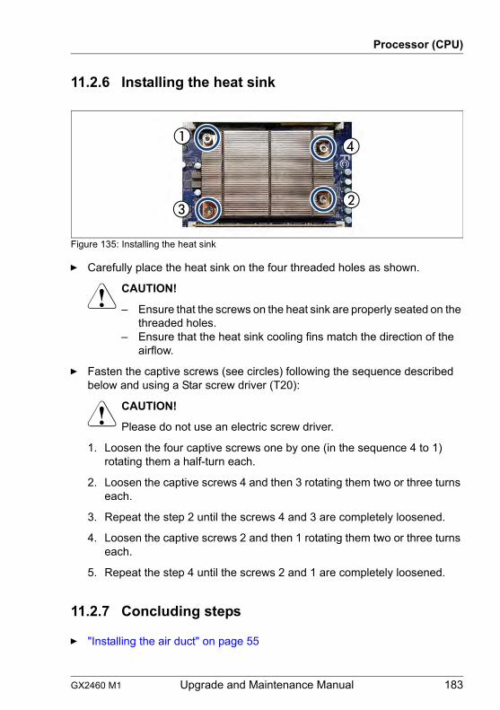
GX2460 M1 Upgrade and Maintenance Manual 183
Processor (CPU)
11.2.6 Installing the heat sink
Figure 135: Installing the heat sink
Ê Carefully place the heat sink on the four threaded holes as shown.
V CAUTION!
– Ensure that the screws on the heat sink are properly seated on the threaded holes.
– Ensure that the heat sink cooling fins match the direction of the airflow.
Ê Fasten the captive screws (see circles) following the sequence described below and using a Star screw driver (T20):
V CAUTION!
Please do not use an electric screw driver.
1. Loosen the four captive screws one by one (in the sequence 4 to 1) rotating them a half-turn each.
2. Loosen the captive screws 4 and then 3 rotating them two or three turns each.
3. Repeat the step 2 until the screws 4 and 3 are completely loosened.
4. Loosen the captive screws 2 and then 1 rotating them two or three turns each.
5. Repeat the step 4 until the screws 2 and 1 are completely loosened.
11.2.7 Concluding steps
Ê "Installing the air duct" on page 55
184 Upgrade and Maintenance Manual GX2460 M1
Processor (CPU)
Ê "Installing the front top cover" on page 49
Ê "Reassembling" on page 50
Ê "Connecting the power cord" on page 53
Ê "Switching on the server" on page 54
I The time setting is initialized when the CPU is replaced and must be reset in the BIOS.
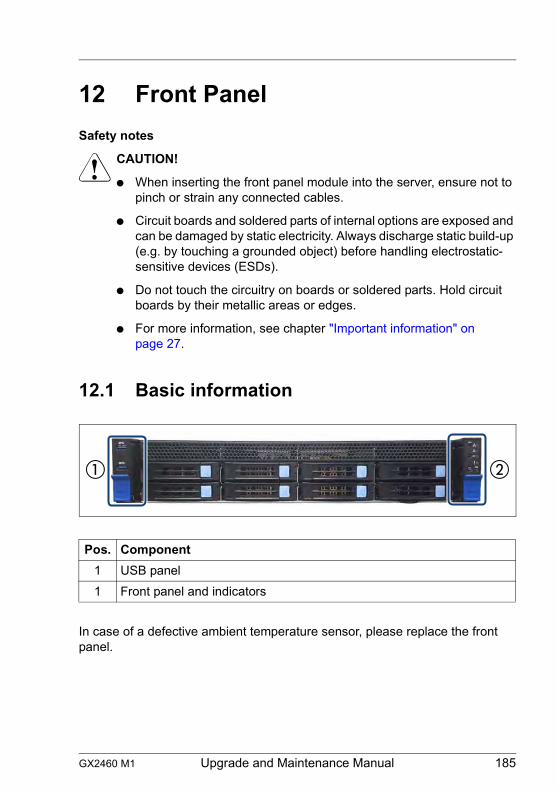
GX2460 M1 Upgrade and Maintenance Manual 185
12 Front PanelSafety notes
V CAUTION!
● When inserting the front panel module into the server, ensure not to pinch or strain any connected cables.
● Circuit boards and soldered parts of internal options are exposed and can be damaged by static electricity. Always discharge static build-up (e.g. by touching a grounded object) before handling electrostatic-sensitive devices (ESDs).
● Do not touch the circuitry on boards or soldered parts. Hold circuit boards by their metallic areas or edges.
● For more information, see chapter "Important information" on page 27.
12.1 Basic information
In case of a defective ambient temperature sensor, please replace the front panel.
Pos. Component1 USB panel1 Front panel and indicators
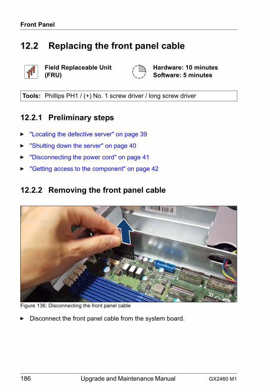
186 Upgrade and Maintenance Manual GX2460 M1
Front Panel
12.2 Replacing the front panel cable
12.2.1 Preliminary steps
Ê "Locating the defective server" on page 39
Ê "Shutting down the server" on page 40
Ê "Disconnecting the power cord" on page 41
Ê "Getting access to the component" on page 42
12.2.2 Removing the front panel cable
Figure 136: Disconnecting the front panel cable
Ê Disconnect the front panel cable from the system board.
Field Replaceable Unit(FRU)
Hardware: 10 minutesSoftware: 5 minutes
Tools: Phillips PH1 / (+) No. 1 screw driver / long screw driver
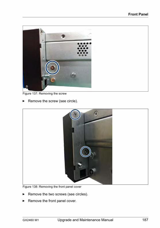
GX2460 M1 Upgrade and Maintenance Manual 187
Front Panel
Figure 137: Removing the screw
Ê Remove the screw (see circle).
Figure 138: Removing the front panel cover
Ê Remove the two screws (see circles).
Ê Remove the front panel cover.
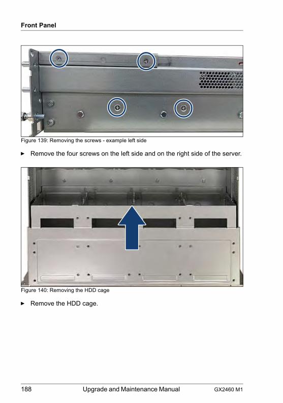
188 Upgrade and Maintenance Manual GX2460 M1
Front Panel
Figure 139: Removing the screws - example left side
Ê Remove the four screws on the left side and on the right side of the server.
Figure 140: Removing the HDD cage
Ê Remove the HDD cage.
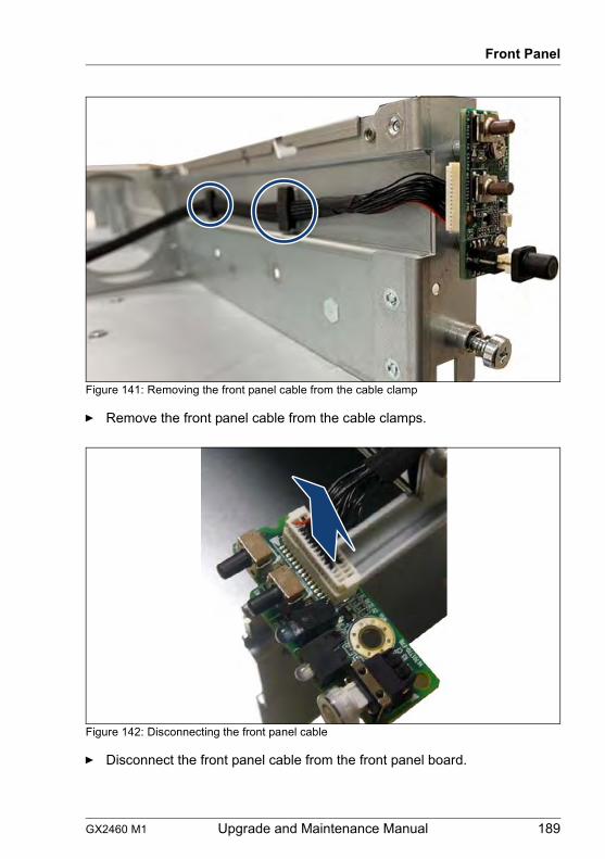
GX2460 M1 Upgrade and Maintenance Manual 189
Front Panel
Figure 141: Removing the front panel cable from the cable clamp
Ê Remove the front panel cable from the cable clamps.
Figure 142: Disconnecting the front panel cable
Ê Disconnect the front panel cable from the front panel board.
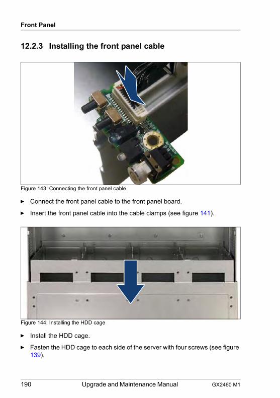
190 Upgrade and Maintenance Manual GX2460 M1
Front Panel
12.2.3 Installing the front panel cable
Figure 143: Connecting the front panel cable
Ê Connect the front panel cable to the front panel board.
Ê Insert the front panel cable into the cable clamps (see figure 141).
Figure 144: Installing the HDD cage
Ê Install the HDD cage.
Ê Fasten the HDD cage to each side of the server with four screws (see figure 139).
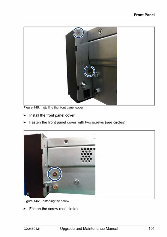
GX2460 M1 Upgrade and Maintenance Manual 191
Front Panel
Figure 145: Installing the front panel cover
Ê Install the front panel cover.
Ê Fasten the front panel cover with two screws (see circles).
Figure 146: Fastening the screw
Ê Fasten the screw (see circle).
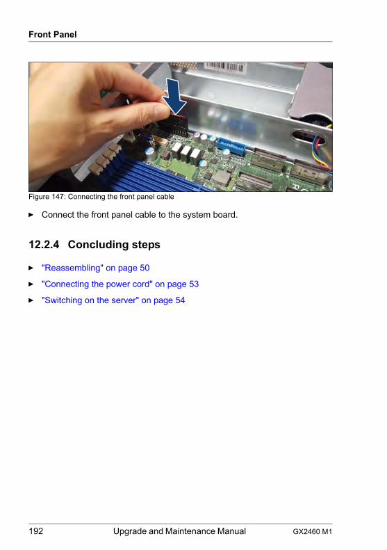
192 Upgrade and Maintenance Manual GX2460 M1
Front Panel
Figure 147: Connecting the front panel cable
Ê Connect the front panel cable to the system board.
12.2.4 Concluding steps
Ê "Reassembling" on page 50
Ê "Connecting the power cord" on page 53
Ê "Switching on the server" on page 54
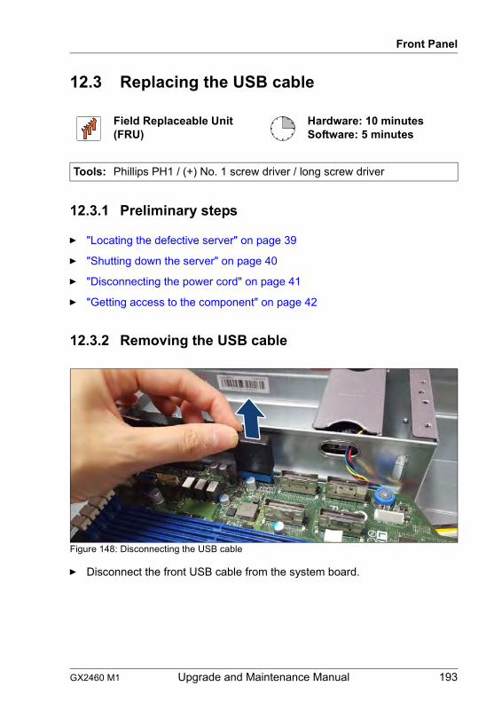
GX2460 M1 Upgrade and Maintenance Manual 193
Front Panel
12.3 Replacing the USB cable
12.3.1 Preliminary steps
Ê "Locating the defective server" on page 39
Ê "Shutting down the server" on page 40
Ê "Disconnecting the power cord" on page 41
Ê "Getting access to the component" on page 42
12.3.2 Removing the USB cable
Figure 148: Disconnecting the USB cable
Ê Disconnect the front USB cable from the system board.
Field Replaceable Unit(FRU)
Hardware: 10 minutesSoftware: 5 minutes
Tools: Phillips PH1 / (+) No. 1 screw driver / long screw driver
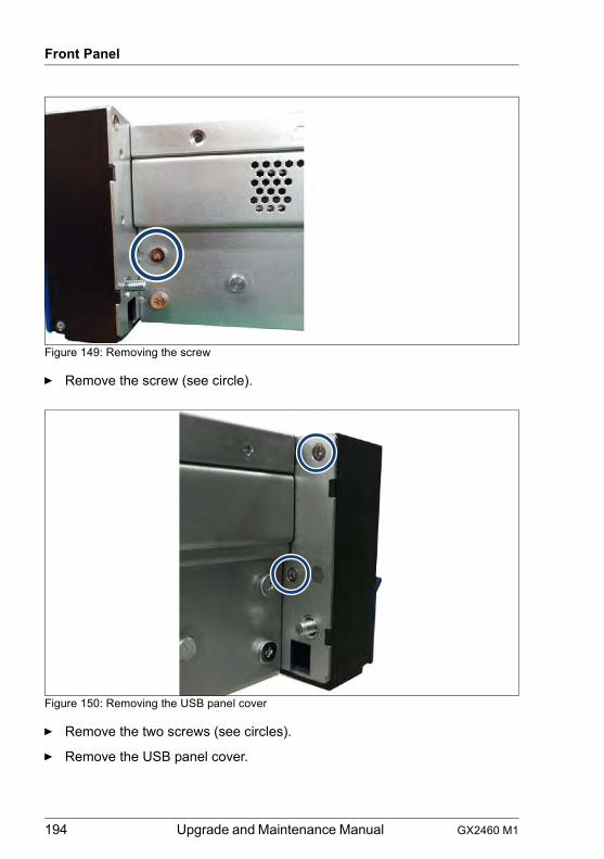
194 Upgrade and Maintenance Manual GX2460 M1
Front Panel
Figure 149: Removing the screw
Ê Remove the screw (see circle).
Figure 150: Removing the USB panel cover
Ê Remove the two screws (see circles).
Ê Remove the USB panel cover.
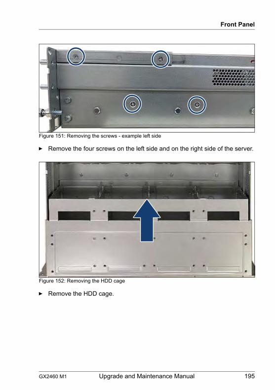
GX2460 M1 Upgrade and Maintenance Manual 195
Front Panel
Figure 151: Removing the screws - example left side
Ê Remove the four screws on the left side and on the right side of the server.
Figure 152: Removing the HDD cage
Ê Remove the HDD cage.
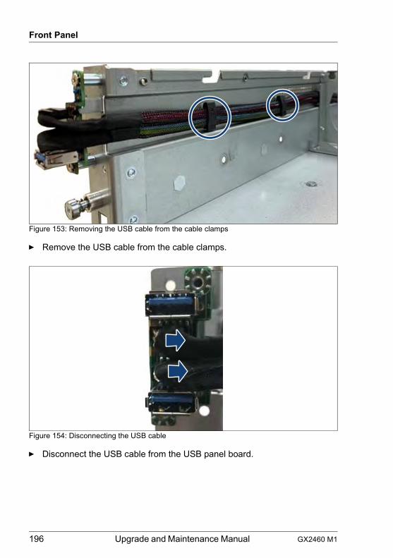
196 Upgrade and Maintenance Manual GX2460 M1
Front Panel
Figure 153: Removing the USB cable from the cable clamps
Ê Remove the USB cable from the cable clamps.
Figure 154: Disconnecting the USB cable
Ê Disconnect the USB cable from the USB panel board.
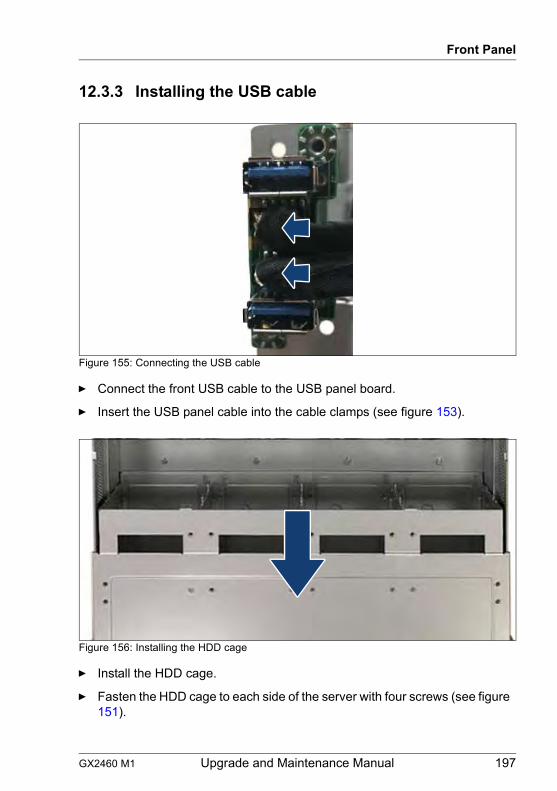
GX2460 M1 Upgrade and Maintenance Manual 197
Front Panel
12.3.3 Installing the USB cable
Figure 155: Connecting the USB cable
Ê Connect the front USB cable to the USB panel board.
Ê Insert the USB panel cable into the cable clamps (see figure 153).
Figure 156: Installing the HDD cage
Ê Install the HDD cage.
Ê Fasten the HDD cage to each side of the server with four screws (see figure 151).
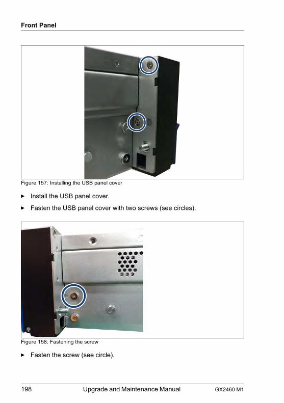
198 Upgrade and Maintenance Manual GX2460 M1
Front Panel
Figure 157: Installing the USB panel cover
Ê Install the USB panel cover.
Ê Fasten the USB panel cover with two screws (see circles).
Figure 158: Fastening the screw
Ê Fasten the screw (see circle).
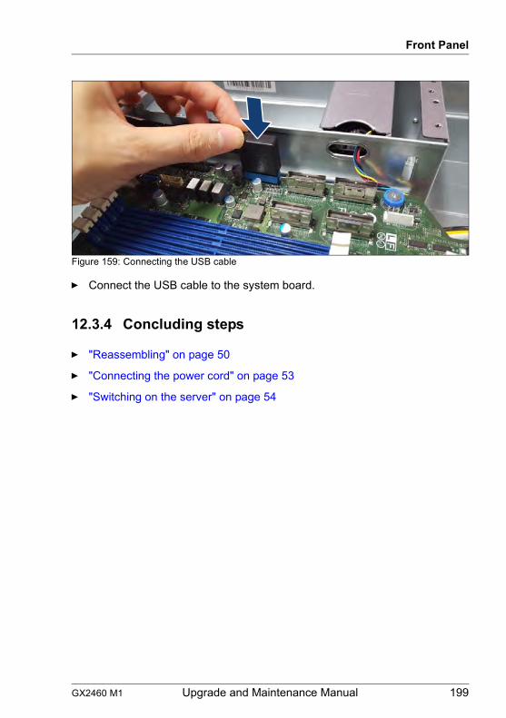
GX2460 M1 Upgrade and Maintenance Manual 199
Front Panel
Figure 159: Connecting the USB cable
Ê Connect the USB cable to the system board.
12.3.4 Concluding steps
Ê "Reassembling" on page 50
Ê "Connecting the power cord" on page 53
Ê "Switching on the server" on page 54
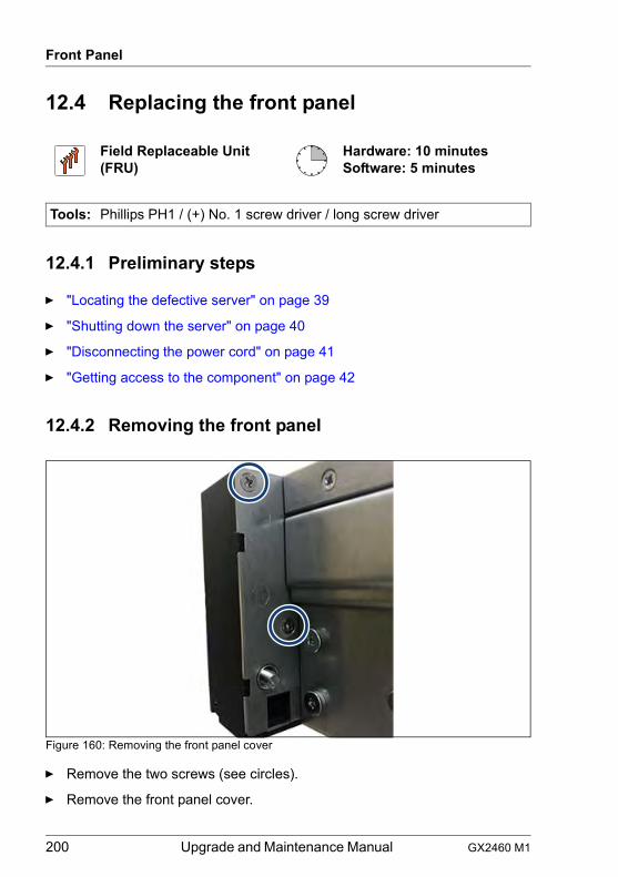
200 Upgrade and Maintenance Manual GX2460 M1
Front Panel
12.4 Replacing the front panel
12.4.1 Preliminary steps
Ê "Locating the defective server" on page 39
Ê "Shutting down the server" on page 40
Ê "Disconnecting the power cord" on page 41
Ê "Getting access to the component" on page 42
12.4.2 Removing the front panel
Figure 160: Removing the front panel cover
Ê Remove the two screws (see circles).
Ê Remove the front panel cover.
Field Replaceable Unit(FRU)
Hardware: 10 minutesSoftware: 5 minutes
Tools: Phillips PH1 / (+) No. 1 screw driver / long screw driver
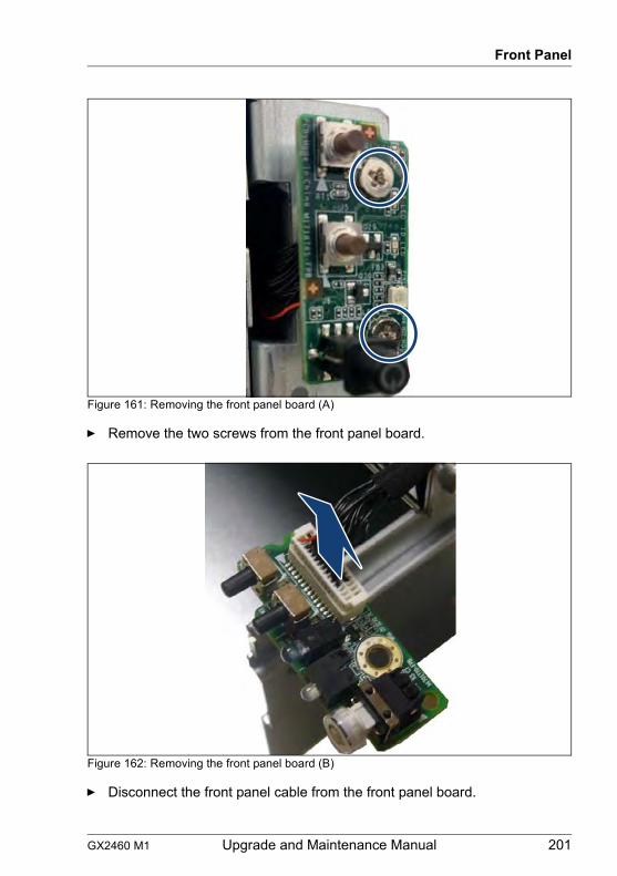
GX2460 M1 Upgrade and Maintenance Manual 201
Front Panel
Figure 161: Removing the front panel board (A)
Ê Remove the two screws from the front panel board.
Figure 162: Removing the front panel board (B)
Ê Disconnect the front panel cable from the front panel board.
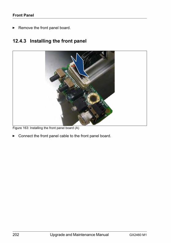
202 Upgrade and Maintenance Manual GX2460 M1
Front Panel
Ê Remove the front panel board.
12.4.3 Installing the front panel
Figure 163: Installing the front panel board (A)
Ê Connect the front panel cable to the front panel board.
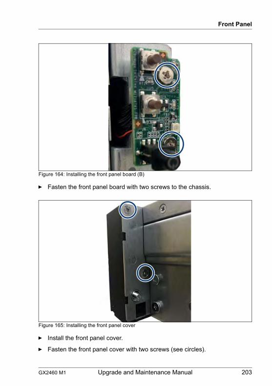
GX2460 M1 Upgrade and Maintenance Manual 203
Front Panel
Figure 164: Installing the front panel board (B)
Ê Fasten the front panel board with two screws to the chassis.
Figure 165: Installing the front panel cover
Ê Install the front panel cover.
Ê Fasten the front panel cover with two screws (see circles).
204 Upgrade and Maintenance Manual GX2460 M1
Front Panel
12.4.4 Concluding steps
Ê "Reassembling" on page 50
Ê "Connecting the power cord" on page 53
Ê "Switching on the server" on page 54
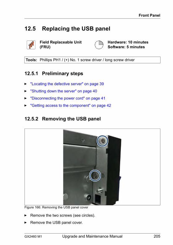
GX2460 M1 Upgrade and Maintenance Manual 205
Front Panel
12.5 Replacing the USB panel
12.5.1 Preliminary steps
Ê "Locating the defective server" on page 39
Ê "Shutting down the server" on page 40
Ê "Disconnecting the power cord" on page 41
Ê "Getting access to the component" on page 42
12.5.2 Removing the USB panel
Figure 166: Removing the USB panel cover
Ê Remove the two screws (see circles).
Ê Remove the USB panel cover.
Field Replaceable Unit(FRU)
Hardware: 10 minutesSoftware: 5 minutes
Tools: Phillips PH1 / (+) No. 1 screw driver / long screw driver
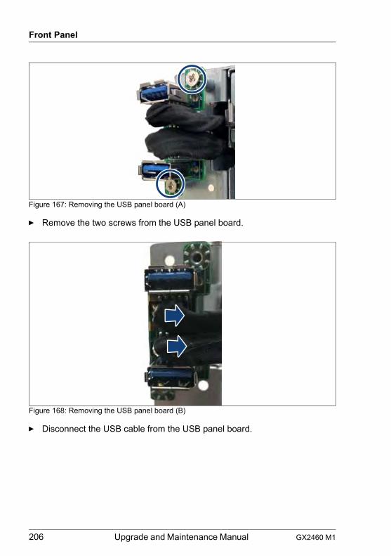
206 Upgrade and Maintenance Manual GX2460 M1
Front Panel
Figure 167: Removing the USB panel board (A)
Ê Remove the two screws from the USB panel board.
Figure 168: Removing the USB panel board (B)
Ê Disconnect the USB cable from the USB panel board.
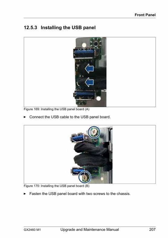
GX2460 M1 Upgrade and Maintenance Manual 207
Front Panel
12.5.3 Installing the USB panel
Figure 169: Installing the USB panel board (A)
Ê Connect the USB cable to the USB panel board.
Figure 170: Installing the USB panel board (B)
Ê Fasten the USB panel board with two screws to the chassis.
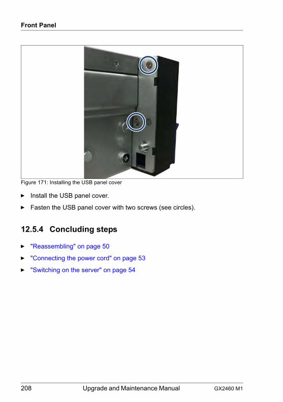
208 Upgrade and Maintenance Manual GX2460 M1
Front Panel
Figure 171: Installing the USB panel cover
Ê Install the USB panel cover.
Ê Fasten the USB panel cover with two screws (see circles).
12.5.4 Concluding steps
Ê "Reassembling" on page 50
Ê "Connecting the power cord" on page 53
Ê "Switching on the server" on page 54
GX2460 M1 Upgrade and Maintenance Manual 209
13 System board and componentsSafety notes
V CAUTION!
● Devices and components inside the server remain hot after shutdown. After shutting down the server, wait for hot components to cool down before installing or removing internal options.
● Circuit boards and soldered parts of internal options are exposed and can be damaged by static electricity. Always discharge static build-up (e.g. by touching a grounded object) before handling electrostatic-sensitive devices (ESDs).
● Do not touch the circuitry on boards or soldered parts. Hold circuit boards by their metallic areas or edges.
● For more information, see chapter "Important information" on page 27.
13.1 Basic information
CMOS battery
The real-time clock is powered by a lithium coin cell (CMOS battery) when mains get lost. This cell lasts up to five years, depending on ambient temperature and use.
If the CMOS battery is depleted or falls below minimum voltage levels, it need to be replaced immediately.
210 Upgrade and Maintenance Manual GX2460 M1
System board and components
13.2 CMOS battery
13.2.1 Replacing the CMOS battery
Safety notes
V CAUTION!
● The CMOS battery must be replaced with an identical battery or with a battery type recommended by the manufacturer.
● Keep lithium batteries away from children.
● Do not throw batteries into the trash can. Lithium batteries must be disposed of in accordance with local regulations concerning special waste.
● For more information, see section "Environmental protection" on page 37.
● Ensure to insert the CMOS battery with the positive pole facing up!
13.2.1.1 Preliminary steps
Ê "Locating the defective server" on page 39
Ê "Verifying the system time settings" on page 59
Ê "Shutting down the server" on page 40
Ê "Disconnecting the power cord" on page 41
Ê "Getting access to the component" on page 42
Upgrade and Repair Unit(URU)
Hardware: 5 minutes
Tools: tool-less; recommended: tooth pick
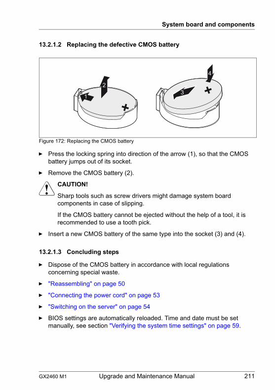
GX2460 M1 Upgrade and Maintenance Manual 211
System board and components
13.2.1.2 Replacing the defective CMOS battery
Figure 172: Replacing the CMOS battery
Ê Press the locking spring into direction of the arrow (1), so that the CMOS battery jumps out of its socket.
Ê Remove the CMOS battery (2).
V CAUTION!
Sharp tools such as screw drivers might damage system board components in case of slipping.
If the CMOS battery cannot be ejected without the help of a tool, it is recommended to use a tooth pick.
Ê Insert a new CMOS battery of the same type into the socket (3) and (4).
13.2.1.3 Concluding steps
Ê Dispose of the CMOS battery in accordance with local regulations concerning special waste.
Ê "Reassembling" on page 50
Ê "Connecting the power cord" on page 53
Ê "Switching on the server" on page 54
Ê BIOS settings are automatically reloaded. Time and date must be set manually, see section "Verifying the system time settings" on page 59.
1
23
4
212 Upgrade and Maintenance Manual GX2460 M1
System board and components
13.3 System board
13.3.1 Replacing the system board
Note on network settings recovery
I When replacing the system board, network configuration settings in the system will be lost and replaced by default values. This applies to all static IP address and LAN teaming configurations.
Ensure to note down your current network settings before replacing the system board.
Note on configurations with LRDIMMs
I After replacing the system board, it is necessary to set the memory operation mode in the BIOS in the same way as before.
Field Replaceable Unit(FRU)
Hardware: 50 minutesSoftware: 10 minutes
Tools: Replacing the system board:
– Phillips PH2 / (+) No. 2 screw driver– hexagon screw driver 5 mm (for OCP bolts)– Magnifying glass for inspecting CPU socket springs
(recommended)
Replacing the TPM:
– Bit screw driver– flat nose pliers– TPM bit insert (*)
– thin slotted screw driver (2 x 0.4 mm) (*)
(*) For Japan:
– Dedicated TPM screw driver (CWZ8291A)– TPM module fixing tool (S26361-F3552-L909)
If an OCP module is installed:
– Phillips PH1 / (+) No. 1 screw driver
GX2460 M1 Upgrade and Maintenance Manual 213
System board and components
Ensure to note down your current BIOS settings before replacing the system board.
13.3.1.1 Preliminary steps
Ê "Locating the defective server" on page 39
Ê "Note on network settings recovery" on page 212
Ê "Shutting down the server" on page 40
Ê "Disconnecting the power cord" on page 41
Ê Disconnect all external cables.
Ê "Getting access to the component" on page 42
Ê Remove the PSUs see, section"Removing a hot-plug PSU" on page 70.
Ê "Removing the air duct" on page 55
Ê If applicable, remove the riser modules, see section "Removing the middle riser module" on page 112 and "Removing the left or right PCIe/GPU riser module" on page 133.
Ê Remove all memory modules, see section "Removing memory modules" on page 168.
I Before removing the memory modules, take a note on the installation slot number for each memory module. Ensure that you install the memory modules in the slot they were located before the replacement.
Ê If applicable, remove all dummy memory modules, see section "Removing memory modules" on page 168.
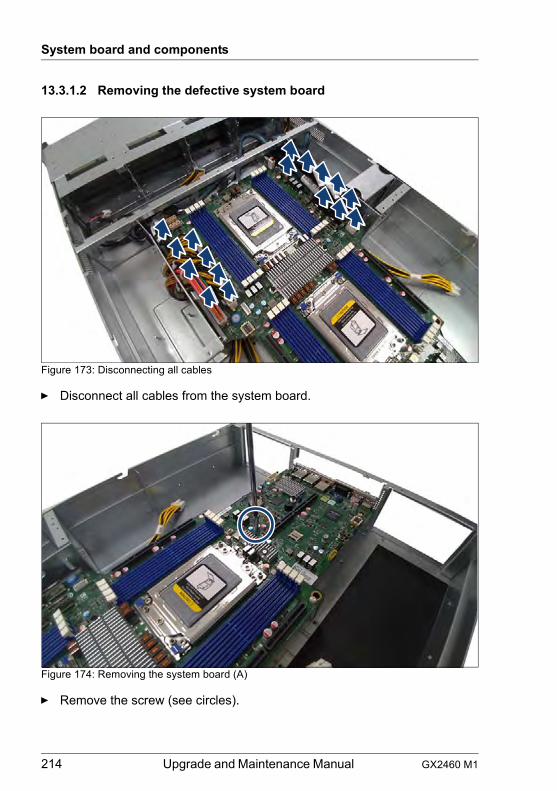
214 Upgrade and Maintenance Manual GX2460 M1
System board and components
13.3.1.2 Removing the defective system board
Figure 173: Disconnecting all cables
Ê Disconnect all cables from the system board.
Figure 174: Removing the system board (A)
Ê Remove the screw (see circles).
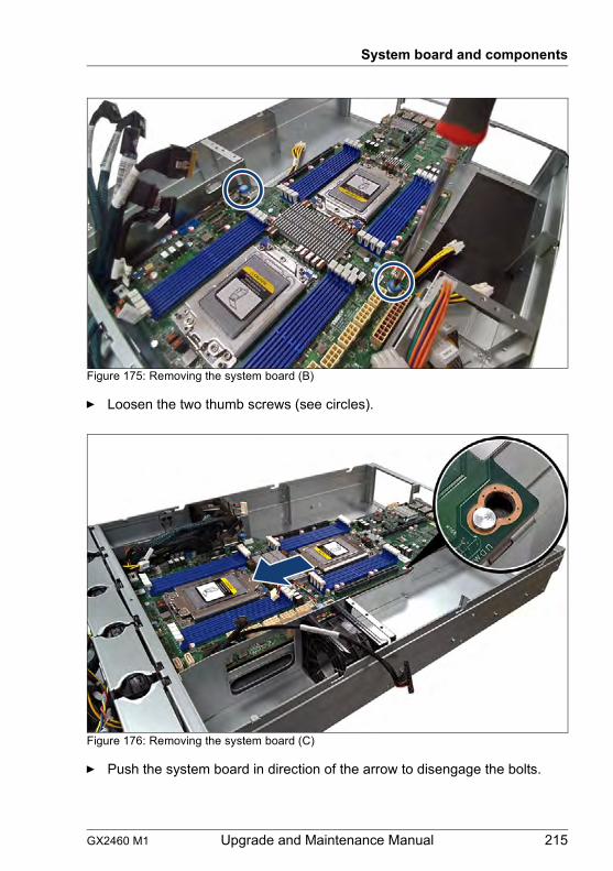
GX2460 M1 Upgrade and Maintenance Manual 215
System board and components
Figure 175: Removing the system board (B)
Ê Loosen the two thumb screws (see circles).
Figure 176: Removing the system board (C)
Ê Push the system board in direction of the arrow to disengage the bolts.
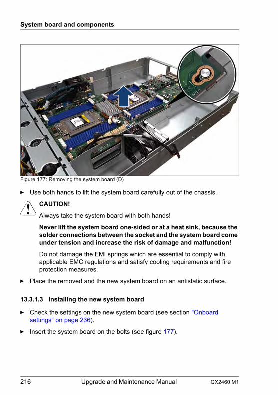
216 Upgrade and Maintenance Manual GX2460 M1
System board and components
Figure 177: Removing the system board (D)
Ê Use both hands to lift the system board carefully out of the chassis.
V CAUTION!
Always take the system board with both hands!
Never lift the system board one-sided or at a heat sink, because the solder connections between the socket and the system board come under tension and increase the risk of damage and malfunction!
Do not damage the EMI springs which are essential to comply with applicable EMC regulations and satisfy cooling requirements and fire protection measures.
Ê Place the removed and the new system board on an antistatic surface.
13.3.1.3 Installing the new system board
Ê Check the settings on the new system board (see section "Onboard settings" on page 236).
Ê Insert the system board on the bolts (see figure 177).
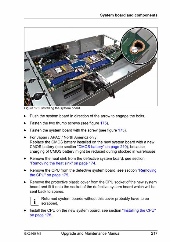
GX2460 M1 Upgrade and Maintenance Manual 217
System board and components
Figure 178: Installing the system board
Ê Push the system board in direction of the arrow to engage the bolts.
Ê Fasten the two thumb screws (see figure 175).
Ê Fasten the system board with the screw (see figure 175).
Ê For Japan / APAC / North America only:Replace the CMOS battery installed on the new system board with a new CMOS battery (see section "CMOS battery" on page 210), because charging of CMOS battery might be reduced during stocked in warehouse.
Ê Remove the heat sink from the defective system board, see section "Removing the heat sink" on page 174.
Ê Remove the CPU from the defective system board, see section "Removing the CPU" on page 175.
Ê Remove the protective plastic cover from the CPU socket of the new system board and fit it onto the socket of the defective system board which will be sent back to spares.
I Returned system boards without this cover probably have to be scrapped.
Ê Install the CPU on the new system board, see section "Installing the CPU" on page 178.
218 Upgrade and Maintenance Manual GX2460 M1
System board and components
Ê Install the heat sink with on the new system board, see section "Installing the heat sink" on page 183.
Ê Connect all cables to the system board:
I For the cable plan, see chapter "Appendix B" on page 243.
13.3.1.4 Concluding steps
Ê Install all memory modules, see section "Installing memory modules" on page 165.
I Ensure that you install each memory module in the slot it was located before the replacement.
Ê If applicable, remove the riser modules, see section "Removing the middle riser module" on page 112 and "Removing the left or right PCIe/GPU riser module" on page 133.
Ê "Installing the air duct" on page 55
Ê "Reassembling" on page 50
Ê Install the PSUs, see section "Installing a hot-plug PSU" on page 67.
Ê Connect all external cables.
Ê "Connecting the power cord" on page 53
Ê "Verifying the system time settings" on page 59
Ê "Updating or recovering the BIOS and BMC" on page 58
Ê For memory configurations with LRDIMMs: set the memory operation mode in the BIOS in the same way as before replacing the system board. For more information, see the corresponding BIOS Setup Utility reference manual.
Ê "Looking for MAC addresses" on page 63
Ê "Updating the NIC configuration file in a Linux environment" on page 61
Ê If applicable, reconfigure your network settings in the operating system according to the original configuration of the replaced controller (expansion card or onboard).
I Configuration of network settings should be performed by the customer. For more information, see section "Note on network settings recovery" on page 212.
Ê If applicable, restore LAN teaming configurations.
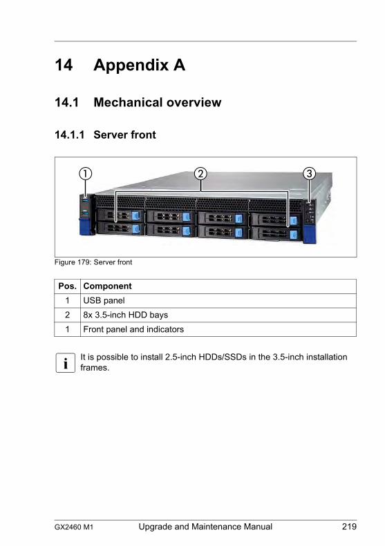
GX2460 M1 Upgrade and Maintenance Manual 219
14 Appendix A
14.1 Mechanical overview
14.1.1 Server front
Figure 179: Server front
I It is possible to install 2.5-inch HDDs/SSDs in the 3.5-inch installation frames.
Pos. Component1 USB panel2 8x 3.5-inch HDD bays1 Front panel and indicators
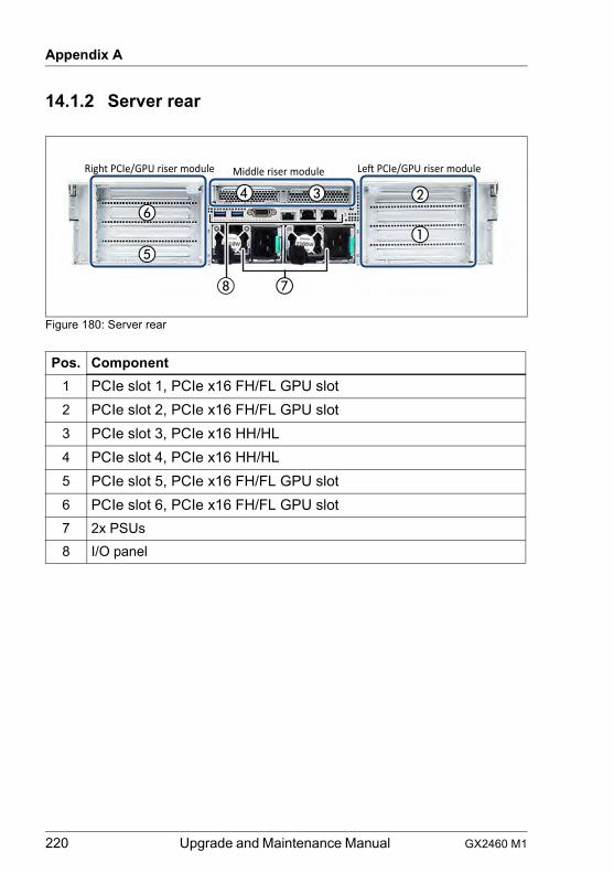
220 Upgrade and Maintenance Manual GX2460 M1
Appendix A
14.1.2 Server rear
Figure 180: Server rear
Pos. Component1 PCIe slot 1, PCIe x16 FH/FL GPU slot2 PCIe slot 2, PCIe x16 FH/FL GPU slot3 PCIe slot 3, PCIe x16 HH/HL4 PCIe slot 4, PCIe x16 HH/HL5 PCIe slot 5, PCIe x16 FH/FL GPU slot6 PCIe slot 6, PCIe x16 FH/FL GPU slot7 2x PSUs8 I/O panel
Right PCIe/GPU riser module Middle riser module
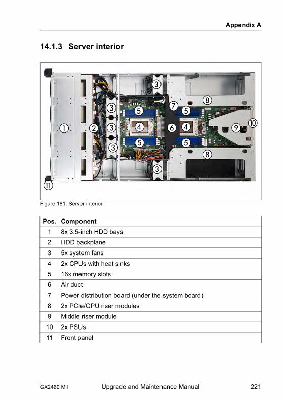
GX2460 M1 Upgrade and Maintenance Manual 221
Appendix A
14.1.3 Server interior
Figure 181: Server interior
Pos. Component1 8x 3.5-inch HDD bays2 HDD backplane3 5x system fans4 2x CPUs with heat sinks5 16x memory slots6 Air duct7 Power distribution board (under the system board)8 2x PCIe/GPU riser modules9 Middle riser module
10 2x PSUs11 Front panel
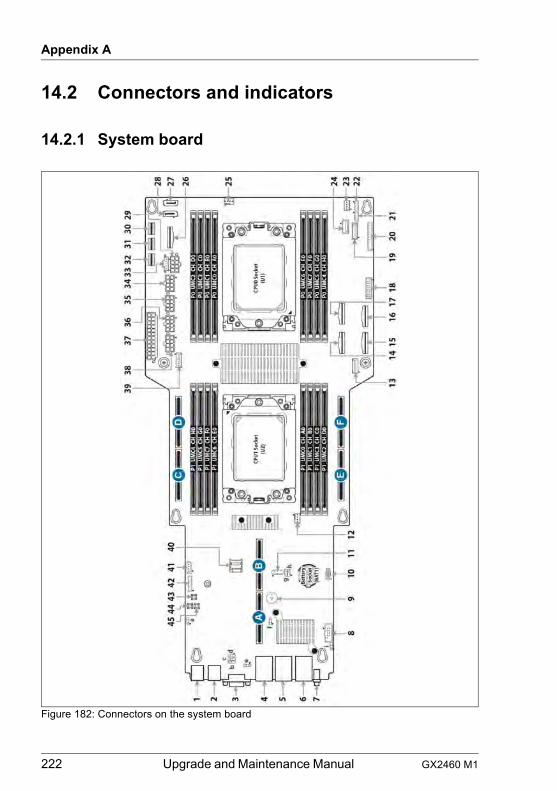
222 Upgrade and Maintenance Manual GX2460 M1
Appendix A
14.2 Connectors and indicators
14.2.1 System board
Figure 182: Connectors on the system board
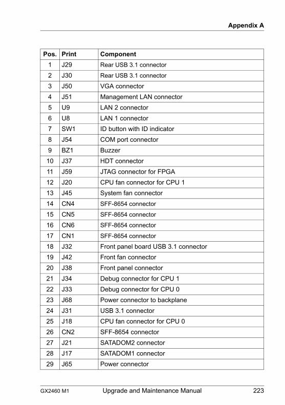
GX2460 M1 Upgrade and Maintenance Manual 223
Appendix A
Pos. Print Component1 J29 Rear USB 3.1 connector
2 J30 Rear USB 3.1 connector
3 J50 VGA connector4 J51 Management LAN connector5 U9 LAN 2 connector6 U8 LAN 1 connector7 SW1 ID button with ID indicator8 J54 COM port connector9 BZ1 Buzzer
10 J37 HDT connector11 J59 JTAG connector for FPGA12 J20 CPU fan connector for CPU 113 J45 System fan connector14 CN4 SFF-8654 connector
15 CN5 SFF-8654 connector
16 CN6 SFF-8654 connector
17 CN1 SFF-8654 connector
18 J32 Front panel board USB 3.1 connector19 J42 Front fan connector20 J38 Front panel connector21 J34 Debug connector for CPU 122 J33 Debug connector for CPU 023 J68 Power connector to backplane24 J31 USB 3.1 connector25 J18 CPU fan connector for CPU 026 CN2 SFF-8654 connector27 J21 SATADOM2 connector28 J17 SATADOM1 connector29 J65 Power connector
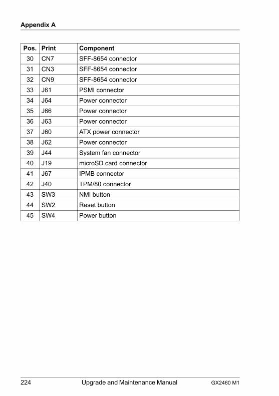
224 Upgrade and Maintenance Manual GX2460 M1
Appendix A
30 CN7 SFF-8654 connector31 CN3 SFF-8654 connector32 CN9 SFF-8654 connector33 J61 PSMI connector34 J64 Power connector35 J66 Power connector36 J63 Power connector37 J60 ATX power connector38 J62 Power connector39 J44 System fan connector40 J19 microSD card connector41 J67 IPMB connector42 J40 TPM/80 connector43 SW3 NMI button44 SW2 Reset button45 SW4 Power button
Pos. Print Component
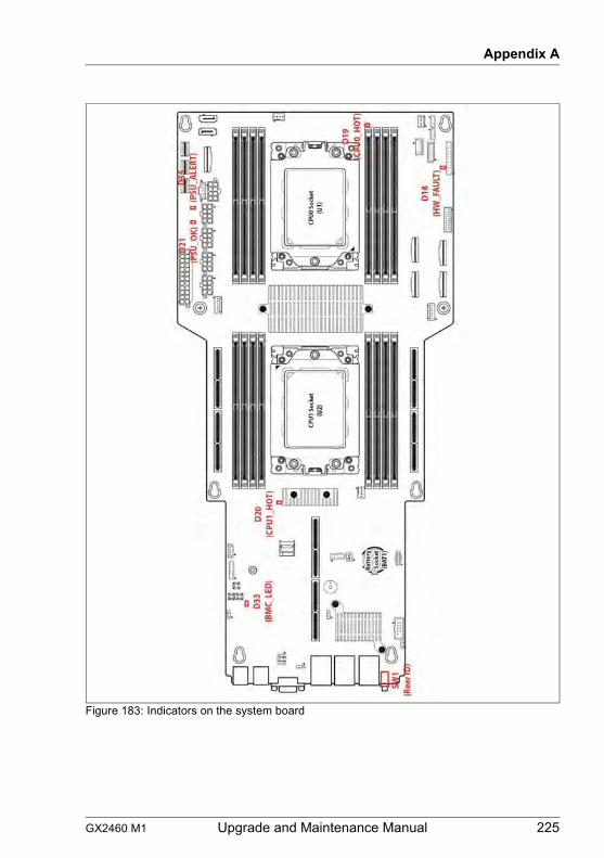
GX2460 M1 Upgrade and Maintenance Manual 225
Appendix A
Figure 183: Indicators on the system board
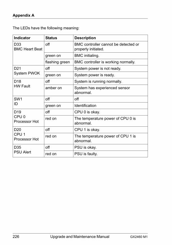
226 Upgrade and Maintenance Manual GX2460 M1
Appendix A
The LEDs have the following meaning:
Indicator Status DescriptionD33BMC Heart Beat
off BMC controller cannot be detected or properly initiated.
green on BMC initialing.flashing green BMC controller is working normally.
D21System PWOK
off System power is not ready.green on System power is ready.
D18HW Fault
off System is running normally.amber on System has experienced sensor
abnormal.SW1ID
off offgreen on Identification
D19CPU 0 Processor Hot
off CPU 0 is okay.red on The temperature power of CPU 0 is
abnormal.D20CPU 1 Processor Hot
off CPU 1 is okay.red on The temperature power of CPU 1 is
abnormal.D35PSU Alert
off PSU is okay.red on PSU is faulty.
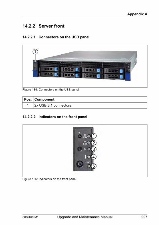
GX2460 M1 Upgrade and Maintenance Manual 227
Appendix A
14.2.2 Server front
14.2.2.1 Connectors on the USB panel
Figure 184: Connectors on the USB panel
14.2.2.2 Indicators on the front panel
Figure 185: Indicators on the front panel
Pos. Component1 2x USB 3.1 connectors
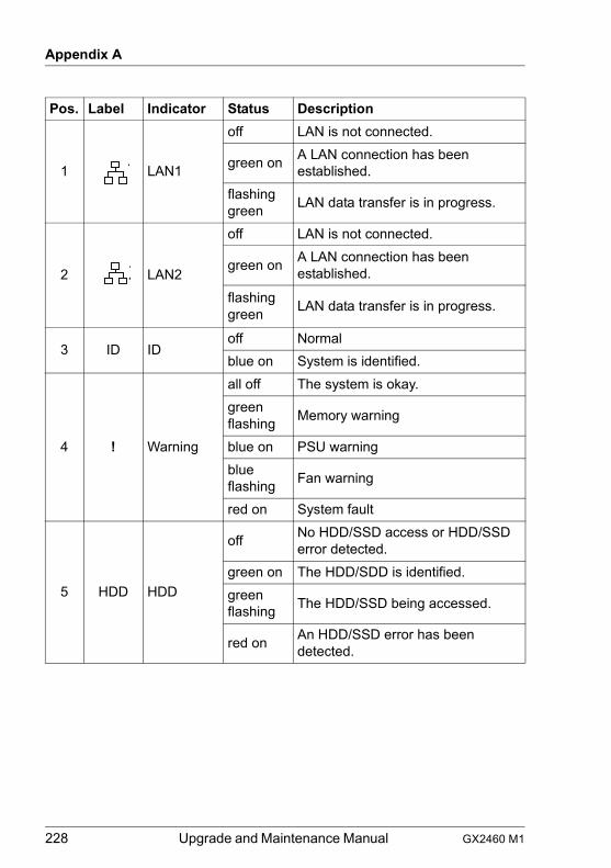
228 Upgrade and Maintenance Manual GX2460 M1
Appendix A
Pos. Label Indicator Status Description
1 LAN1
off LAN is not connected.
green on A LAN connection has been established.
flashing green LAN data transfer is in progress.
2 LAN2
off LAN is not connected.
green on A LAN connection has been established.
flashing green LAN data transfer is in progress.
3 ID IDoff Normalblue on System is identified.
4 ! Warning
all off The system is okay.green flashing Memory warning
blue on PSU warningblue flashing Fan warning
red on System fault
5 HDD HDD
off No HDD/SSD access or HDD/SSD error detected.
green on The HDD/SDD is identified.green flashing The HDD/SSD being accessed.
red on An HDD/SSD error has been detected.
1
2
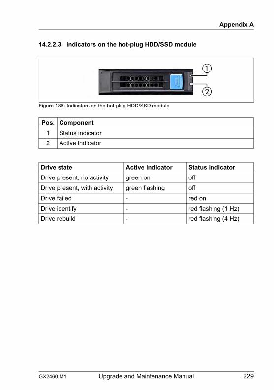
GX2460 M1 Upgrade and Maintenance Manual 229
Appendix A
14.2.2.3 Indicators on the hot-plug HDD/SSD module
Figure 186: Indicators on the hot-plug HDD/SSD module
Pos. Component1 Status indicator2 Active indicator
Drive state Active indicator Status indicatorDrive present, no activity green on offDrive present, with activity green flashing offDrive failed - red onDrive identify - red flashing (1 Hz)Drive rebuild - red flashing (4 Hz)
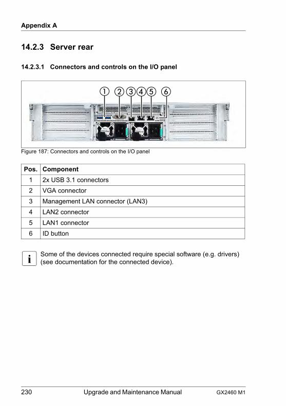
230 Upgrade and Maintenance Manual GX2460 M1
Appendix A
14.2.3 Server rear
14.2.3.1 Connectors and controls on the I/O panel
Figure 187: Connectors and controls on the I/O panel
I Some of the devices connected require special software (e.g. drivers) (see documentation for the connected device).
Pos. Component1 2x USB 3.1 connectors2 VGA connector3 Management LAN connector (LAN3)4 LAN2 connector5 LAN1 connector6 ID button
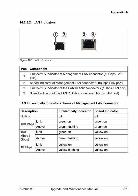
GX2460 M1 Upgrade and Maintenance Manual 231
Appendix A
14.2.3.2 LAN indicators
Figure 188: LAN indicators
LAN Link/activity indicator scheme of Management LAN connector
Pos. Component
1 Link/activity indicator of Management LAN connector (10Gbps LAN port)
2 Speed indicator of Management LAN connector (10Gbps LAN port)2 Link/activity indicator of the LAN1/LAN2 connectors (1Gbps LAN port)2 Speed indicator of the LAN1/LAN2 connectors (1Gbps LAN port)
Description Link/activity indicator Speed indicatorNo link off off
100 MbpsLink green on green onActive green flashing green on
1000 Mbps (1 Gbps)
Link green on yellow on
Active green flashing yellow on
10 GbpsLink yellow on yellow onActive yellow flashing yellow on
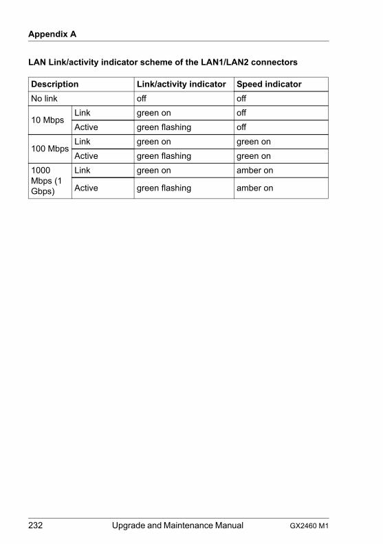
232 Upgrade and Maintenance Manual GX2460 M1
Appendix A
LAN Link/activity indicator scheme of the LAN1/LAN2 connectors
Description Link/activity indicator Speed indicatorNo link off off
10 MbpsLink green on offActive green flashing off
100 MbpsLink green on green onActive green flashing green on
1000 Mbps (1 Gbps)
Link green on amber on
Active green flashing amber on
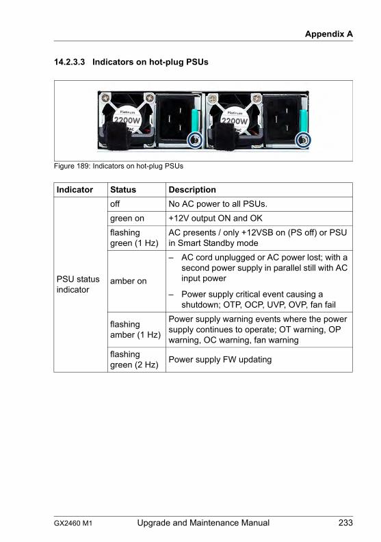
GX2460 M1 Upgrade and Maintenance Manual 233
Appendix A
14.2.3.3 Indicators on hot-plug PSUs
Figure 189: Indicators on hot-plug PSUs
Indicator Status Description
PSU status indicator
off No AC power to all PSUs.green on +12V output ON and OKflashing green (1 Hz)
AC presents / only +12VSB on (PS off) or PSU in Smart Standby mode
amber on
– AC cord unplugged or AC power lost; with a second power supply in parallel still with AC input power
– Power supply critical event causing a shutdown; OTP, OCP, UVP, OVP, fan fail
flashing amber (1 Hz)
Power supply warning events where the power supply continues to operate; OT warning, OP warning, OC warning, fan warning
flashing green (2 Hz) Power supply FW updating
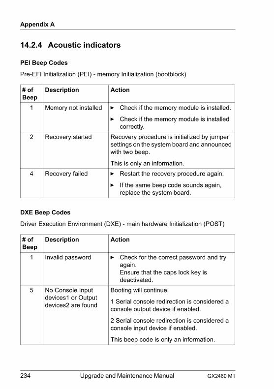
234 Upgrade and Maintenance Manual GX2460 M1
Appendix A
14.2.4 Acoustic indicators
PEI Beep Codes
Pre-EFI Initialization (PEI) - memory Initialization (bootblock)
DXE Beep Codes
Driver Execution Environment (DXE) - main hardware Initialization (POST)
# of Beep
Description Action
1 Memory not installed Ê Check if the memory module is installed.
Ê Check if the memory module is installed correctly.
2 Recovery started Recovery procedure is initialized by jumper settings on the system board and announced with two beep.
This is only an information.4 Recovery failed Ê Restart the recovery procedure again.
Ê If the same beep code sounds again, replace the system board.
# of Beep
Description Action
1 Invalid password Ê Check for the correct password and try again.Ensure that the caps lock key is deactivated.
5 No Console Input devices1 or Output devices2 are found
Booting will continue.
1 Serial console redirection is considered a console output device if enabled.
2 Serial console redirection is considered a console input device if enabled.
This beep code is only an information.
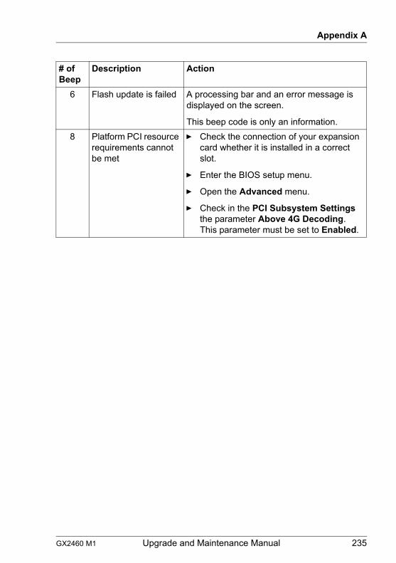
GX2460 M1 Upgrade and Maintenance Manual 235
Appendix A
6 Flash update is failed A processing bar and an error message is displayed on the screen.
This beep code is only an information.8 Platform PCI resource
requirements cannot be met
Ê Check the connection of your expansion card whether it is installed in a correct slot.
Ê Enter the BIOS setup menu.
Ê Open the Advanced menu.
Ê Check in the PCI Subsystem Settings the parameter Above 4G Decoding.This parameter must be set to Enabled.
# of Beep
Description Action
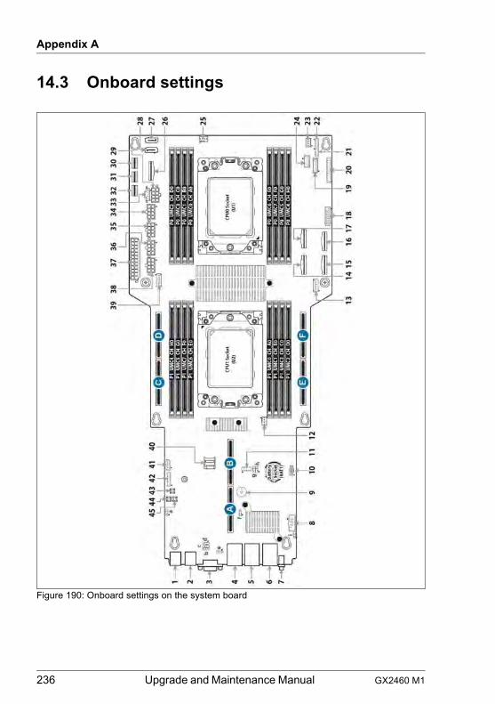
236 Upgrade and Maintenance Manual GX2460 M1
Appendix A
14.3 Onboard settings
Figure 190: Onboard settings on the system board
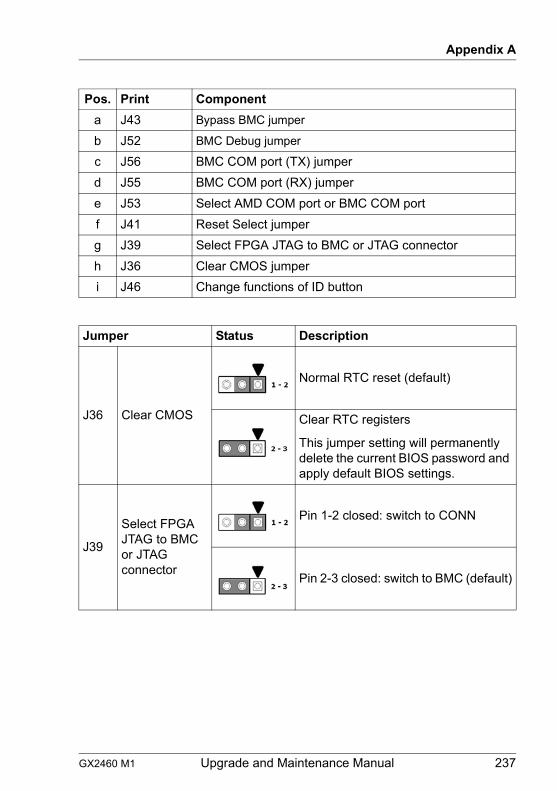
GX2460 M1 Upgrade and Maintenance Manual 237
Appendix A
Pos. Print Componenta J43 Bypass BMC jumper
b J52 BMC Debug jumper
c J56 BMC COM port (TX) jumperd J55 BMC COM port (RX) jumpere J53 Select AMD COM port or BMC COM portf J41 Reset Select jumperg J39 Select FPGA JTAG to BMC or JTAG connectorh J36 Clear CMOS jumperi J46 Change functions of ID button
Jumper Status Description
J36 Clear CMOS
Normal RTC reset (default)
Clear RTC registers
This jumper setting will permanently delete the current BIOS password and apply default BIOS settings.
J39
Select FPGA JTAG to BMC or JTAG connector
Pin 1-2 closed: switch to CONN
Pin 2-3 closed: switch to BMC (default)

238 Upgrade and Maintenance Manual GX2460 M1
Appendix A
J41 Reset Select
Pin 1-2 closed: FP reset button =system reset (default)
Pin 2-3 closed: FP reset button = BMC reset
J43 Bypass BMC
Pin 1-2 closed: Bypass BMC
Pin 2-3 closed: FPGA waits for BMC ready (default)
J46Change functions of ID Button
Pin 1-2 closed: press 5 seconds for BMC HW reset
Pin 2-3 closed: press 5 seconds for power on/off (default)
J53Select AMD COM port or BMC COM port
Pin 1-2 closed: AMD COM port 0
Pin 2-3 closed: BMC COM port 1 (default)
Jumper Status Description
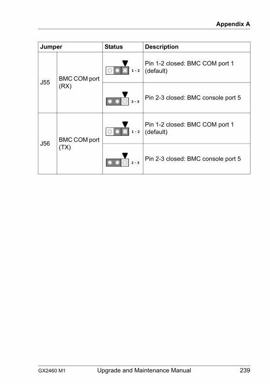
GX2460 M1 Upgrade and Maintenance Manual 239
Appendix A
J55 BMC COM port (RX)
Pin 1-2 closed: BMC COM port 1 (default)
Pin 2-3 closed: BMC console port 5
J56 BMC COM port (TX)
Pin 1-2 closed: BMC COM port 1 (default)
Pin 2-3 closed: BMC console port 5
Jumper Status Description
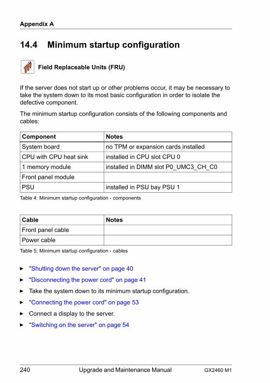
240 Upgrade and Maintenance Manual GX2460 M1
Appendix A
14.4 Minimum startup configuration
If the server does not start up or other problems occur, it may be necessary to take the system down to its most basic configuration in order to isolate the defective component.
The minimum startup configuration consists of the following components and cables:
Ê "Shutting down the server" on page 40
Ê "Disconnecting the power cord" on page 41
Ê Take the system down to its minimum startup configuration.
Ê "Connecting the power cord" on page 53
Ê Connect a display to the server.
Ê "Switching on the server" on page 54
Field Replaceable Units (FRU)
Component NotesSystem board no TPM or expansion cards installedCPU with CPU heat sink installed in CPU slot CPU 01 memory module installed in DIMM slot P0_UMC3_CH_C0Front panel modulePSU installed in PSU bay PSU 1
Table 4: Minimum startup configuration - components
Cable NotesFront panel cablePower cable
Table 5: Minimum startup configuration - cables
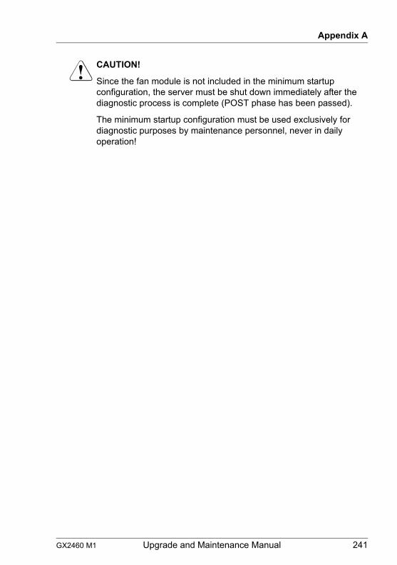
GX2460 M1 Upgrade and Maintenance Manual 241
Appendix A
V CAUTION!
Since the fan module is not included in the minimum startup configuration, the server must be shut down immediately after the diagnostic process is complete (POST phase has been passed).
The minimum startup configuration must be used exclusively for diagnostic purposes by maintenance personnel, never in daily operation!
242 Upgrade and Maintenance Manual GX2460 M1
Appendix A
GX2460 M1 Upgrade and Maintenance Manual 243
15 Appendix BThe following documents are available in this appendix:
– "Cable plan for FUJITSU Server PRIMERGY GX2460 M1 Reference Manual"
– "List of Released Adapters incl. Installation sequence and priority"
– "List of all used screws for PRIMERGY Servers - Assembled in Germany and Japan"

244 Upgrade and Maintenance Manual GX2460 M1
Appendix B
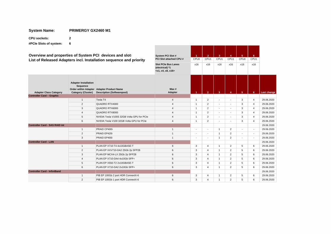
List of Released Adapters incl. Installation sequence and prioritySlot PCIe Bus Lanes (electrical) *1<x1, x4, x8, x16>
Max # Adapter Last change
4 29.06.2020
4 29.06.2020
4 29.06.2020
4 29.06.2020
4 29.06.2020
4 29.06.2020
29.06.20201 29.06.2020
1 29.06.2020
1 29.06.2020
29.06.20206 29.06.2020
6 29.06.2020
6 29.06.2020
6 29.06.2020
6 29.06.2020
6 29.06.2020
29.06.20206 29.06.2020
6 29.06.2020
1 32
6
6
x16 x16 x16 x16 x16
6
-
-
-
6
6
6
6
6
4
4
4
4
4
4
CPU15
CPU0
CPU sockets: 2#PCIe Slots of system:
System Name: PRIMERGY GX2460 M1
6Overview and properties of System PCI devices and slotsPCI Slot attached CPU # CPU0
41 2 3CPU1 CPU1 CPU1
System PCI Slot #
Adapter Class Category
Adapter Installation Sequence
Order within Adapter Category (Cluster)
Adapter Product NameDescription (Softwarepool)
x16
1 Tesla T4 1 2 - -Controller Card – Graphic
2 QUADRO RTX4000 1 2 - -
3
3
4 5
3
3
2 - -
2 - - 3
1 2 - -
3 QUADRO RTX6000 1
4 QUADRO RTX8000
2 PRAID EP420i
5 NVIDIA Tesla V100S 32GB Volta GPU for PCIe 1
2 - -6 NVIDIA Tesla V100 32GB Volta GPU for PCIe 1
- - 1 2
2
1 2
3Controller Card - SAS RAID int
-
-
-
-
1 PRAID CP400i - - 1
5
5
5
5
2
1 PLAN EP X710-T4 4x10GBASE-T 3 4 1 2
3 PRAID EP400i -Controller Card - LAN
3 PLAN EP MCX4-LX 25Gb 2p SFP28 3 4 1 2
5
5PLAN EP X710-DA2 2x10Gb SFP+ 3
5 PLAN EP X550-T2 2x10GBASE-T 3
4
4 PLAN EP X710-DA4 4x10Gb SFP+ 3 4 1 2
4
23 4 1
4 1 2 5
3 4 1
1 2
6
6
1 PIB EP 100Gb 2 port HDR ConnextX-6
1 26
5Controller Card - InfiniBand
2 PLAN EP XXV710-DA2 25Gb 2p SFP28
2 PIB EP 100Gb 1 port HDR ConnextX-6 3
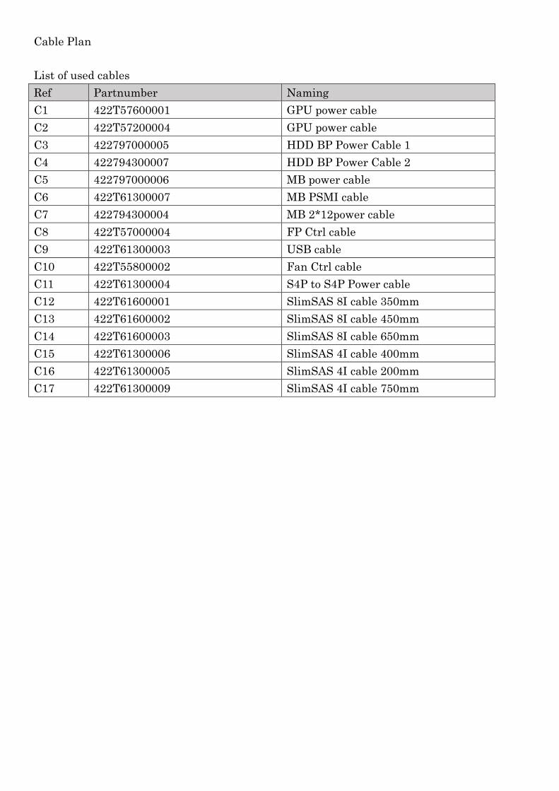
Cable Plan List of used cables Ref Partnumber Naming C1 422T57600001 GPU power cable C2 422T57200004 GPU power cable C3 422797000005 HDD BP Power Cable 1 C4 422794300007 HDD BP Power Cable 2 C5 422797000006 MB power cable C6 422T61300007 MB PSMI cable C7 422794300004 MB 2*12power cable C8 422T57000004 FP Ctrl cable C9 422T61300003 USB cable C10 422T55800002 Fan Ctrl cable C11 422T61300004 S4P to S4P Power cable C12 422T61600001 SlimSAS 8I cable 350mm C13 422T61600002 SlimSAS 8I cable 450mm C14 422T61600003 SlimSAS 8I cable 650mm C15 422T61300006 SlimSAS 4I cable 400mm C16 422T61300005 SlimSAS 4I cable 200mm C17 422T61300009 SlimSAS 4I cable 750mm
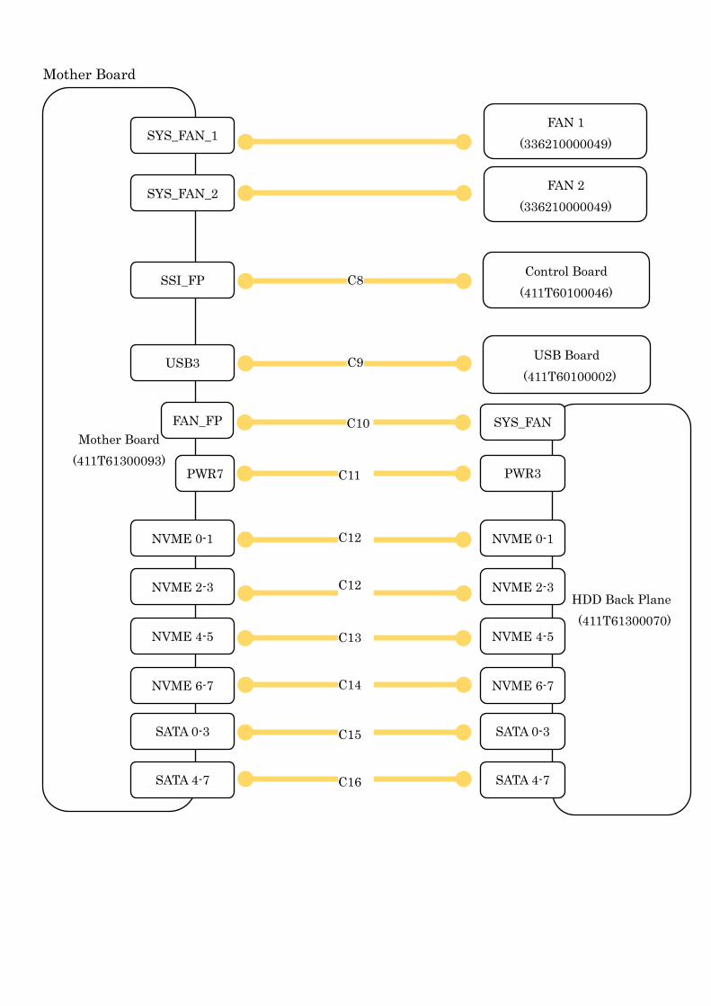
Mother Board
Mother Board (411T61300093)
HDD Back Plane (411T61300070)
C10
C11
NVME 0-1
Control Board (411T60100046)
USB Board (411T60100002)
C8
C9
NVME 2-3
NVME 4-5
NVME 6-7
SATA 0-3
SATA 4-7
NVME 0-1
NVME 2-3
NVME 4-5
NVME 6-7
SATA 0-3
SATA 4-7
C12
C12
C13
C14
C15
C16
FAN 1 (336210000049)
FAN 2 (336210000049)
SSI_FP
FAN_FP
PWR7
USB3
SYS_FAN_1
SYS_FAN_2
PWR3
SYS_FAN
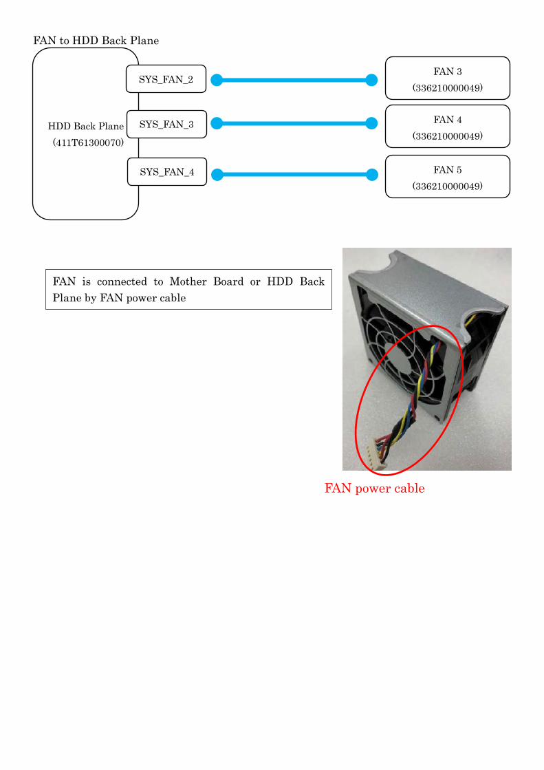
FAN to HDD Back Plane
HDD Back Plane (411T61300070)
FAN 3 (336210000049)
SYS_FAN_2
SYS_FAN_3
SYS_FAN_4
FAN 4 (336210000049)
FAN 5 (336210000049)
FAN is connected to Mother Board or HDD Back Plane by FAN power cable
FAN power cable
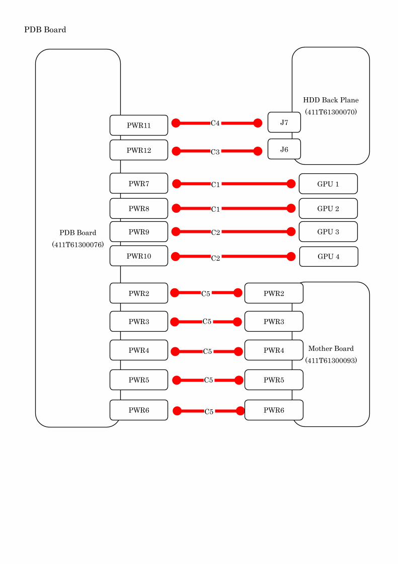
PDB Board
PDB Board (411T61300076)
HDD Back Plane (411T61300070)
J6 C3
GPU 2
GPU 4
C1
C2
C5
Mother Board (411T61300093)
C5
C5
C5
C5
PWR2
PWR3
PWR4
PWR5
PWR6
PWR2
PWR3
PWR4
PWR5
PWR6
GPU 3 C2
GPU 1 C1 PWR7
PWR8
PWR9
PWR10
C4 PWR11
PWR12
J7
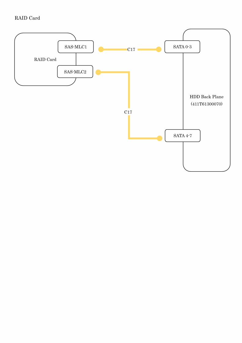
RAID Card
RAID Card
HDD Back Plane (411T61300070)
SAS-MLC1
SAS-MLC2
SATA 0-3
SATA 4-7
C17
C17
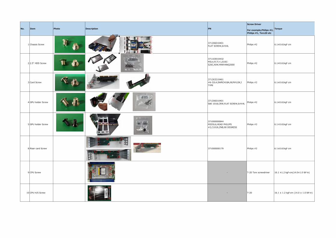
No. Item Photo Description PN
Screw Driver
For example,Philips #2, Philips #1, Torx20 etc
Torque
1 Chassis Screw 371206010401 FLAT SCREW,6#X4L Philips #2 6.1±0.61kgf・cm
2 2.5" HDD Screw
371103010432 M3L4,FLT(+),S10C-S20C,NIW,MARYANG2000 Philips #2 6.1±0.61kgf・cm
3 Card Screw371263210461 #6-32L4,SWRCH18A,NI/NYLOK,I TYPE
Philips #2 6.1±0.61kgf・cm
4 GPU holder Screw 371206010401 SAE 1018,CRW,FLAT SCREW,6#X4L Philips #2 6.1±0.61kgf・cm
5 GPU holder Screw371000000844 M3D5L6,HEAD PHILIPS #2,C1018,ZNB,90 DEGRESS
Philips #2 6.1±0.61kgf・cm
8 Riser card Screw 371000000179 Philips #2 6.1±0.61kgf・cm
9 CPU Screw - T-20 Torx screwdriver 16.1 ±1.2 kgf-cm(14.0±1.0 lbf-in)
10 CPU H/S Screw - T-20 16.1 ± 1.2 kgf-cm (14.0 ± 1.0 lbf-in)