Embed Size (px)
Citation preview
Produktfamilie
PRIMERGY RX800 S2/S3RemoteView Management Board RSA-II User ManualJoachim PicholFujitsu Siemens Computers GmbH Paderborn33094 Paderborne-mail: email: [email protected].: 05251 14888-18Fax: (++49) 700 / 372 00001 Sprachen: En
Edition November 2006
This manual is printed on paper treated with chlorine-free bleach.
Comments… Suggestions… Corrections…The User Documentation Department would like toknow your opinion of this manual. Your feedback helpsus optimize our documentation to suit your individual needs.
Fax forms for sending us your comments are included inthe back of the manual.
There you will also find the addresses of the relevantUser Documentation Department.
Certified documentation according to DIN EN ISO 9001:2000To ensure a consistently high quality standard anduser-friendliness, this documentation was created tomeet the regulations of a quality management system which complies with the requirements of the standardDIN EN ISO 9001:2000.
cognitas. Gesellschaft für Technik-Dokumentation mbHwww.cognitas.de
Copyright and Trademarks
© c
ogni
tas.
Ges
ells
chft
für
Tech
nik-
Dok
umen
tatio
n m
bH 2
006
Pfa
d: D
:\Akt
uelle
s_P
roje
kt\P
RIM
ER
GY
\RX
800S
3\rs
a-rx
800s
2-s3
_us\
RS
A_e
.vor
Copyright © 2006 Fujitsu Siemens Computers GmbH.
All rights reserved.Delivery subject to availability; right of technical modifications reserved.
All hardware and software names used are trademarks of their respective manufacturers.
© c
ogni
tas.
Ges
ells
chft
für
Tech
nik-
Dok
umen
tatio
n m
bH 2
006
Pfa
d: D
:\Akt
uelle
s_P
roje
kt\P
RIM
ER
GY
\RX
800S
3\rs
a-rx
800s
2-s3
_us\
RS
A_e
.vor
Introduction
Opening and using the Web interface
Configuring the RSA-II
Monitoring remote server status
Performing RSA-II tasks
Command-line interface
Related Publications
Index

© c
ogni
tas.
Ges
ells
chft
für
Tech
nik-
Dok
umen
tatio
n m
bH 2
006
Pfa
d: D
:\Akt
uelle
s_P
roje
kt\P
RIM
ER
GY
\RX
800S
3\rs
a-rx
800s
2-s3
_us\
RS
A_e
.vor
Contents1 Introduction . . . . . . . . . . . . . . . . . . . . . . . . . . . . 91.1 Overview of the Documentation . . . . . . . . . . . . . . . . . . 91.2 RSA-II Features . . . . . . . . . . . . . . . . . . . . . . . . . 101.3 Web browser and OS requirements . . . . . . . . . . . . . . . 111.4 Notational Conventions . . . . . . . . . . . . . . . . . . . . . 12
2 Opening and using the Web interface . . . . . . . . . . . . 132.1 Logging in to the RSA-II . . . . . . . . . . . . . . . . . . . . . 132.2 RSA-II action descriptions . . . . . . . . . . . . . . . . . . . . 16
3 Configuring the RSA-II . . . . . . . . . . . . . . . . . . . . . 213.1 Setting system information . . . . . . . . . . . . . . . . . . . 233.1.1 Setting server timeouts . . . . . . . . . . . . . . . . . . . . . 253.1.2 Setting the date and time . . . . . . . . . . . . . . . . . . . . 283.2 Creating a login profile . . . . . . . . . . . . . . . . . . . . . . 303.3 Configuring the global login settings . . . . . . . . . . . . . . . 343.4 Configuring remote alert settings . . . . . . . . . . . . . . . . 363.4.1 Configuring remote alert recipients . . . . . . . . . . . . . . . 363.4.2 Setting remote alert attempts . . . . . . . . . . . . . . . . . . 393.4.3 Setting remote alerts . . . . . . . . . . . . . . . . . . . . . . 413.4.4 Setting local events . . . . . . . . . . . . . . . . . . . . . . . 453.5 Configuring port assignments . . . . . . . . . . . . . . . . . . 473.6 Configuring an Ethernet connection to the RSA-II . . . . . . . . 493.7 Configuring network protocols . . . . . . . . . . . . . . . . . . 543.7.1 Configuring SNMP . . . . . . . . . . . . . . . . . . . . . . . . 543.7.2 Configuring SMTP . . . . . . . . . . . . . . . . . . . . . . . . 573.8 Configuring security . . . . . . . . . . . . . . . . . . . . . . . 583.8.1 SSL certificate overview . . . . . . . . . . . . . . . . . . . . . 593.8.2 SSL server certificate management . . . . . . . . . . . . . . . 593.8.3 Enabling SSL for the secure Web server . . . . . . . . . . . . 683.8.4 SSL client certificate management . . . . . . . . . . . . . . . 683.8.5 SSL client trusted certificate management . . . . . . . . . . . 693.9 Configuring the Secure Shell server . . . . . . . . . . . . . . . 713.9.1 Generating a Secure Shell server key . . . . . . . . . . . . . . 713.9.2 Enabling the Secure Shell server . . . . . . . . . . . . . . . . 723.9.3 Using the Secure Shell server . . . . . . . . . . . . . . . . . . 733.10 Using the configuration file . . . . . . . . . . . . . . . . . . . 743.10.1 Backing up your current configuration . . . . . . . . . . . . . . 753.10.2 Restoring and modifying your ASM configuration . . . . . . . . 753.12 Restarting ASM . . . . . . . . . . . . . . . . . . . . . . . . . 773.13 Logging off . . . . . . . . . . . . . . . . . . . . . . . . . . . . 78
Contents
© c
ogni
tas.
Ges
ells
chft
für
Tech
nik-
Dok
umen
tatio
n m
bH 2
006
Pfa
d: D
:\Akt
uelle
s_P
roje
kt\P
RIM
ER
GY
\RX
800S
3\rs
a-rx
800s
2-s3
_us\
RS
A_e
.ivz
4 Monitoring remote server status . . . . . . . . . . . . . . . . 794.1 Viewing system health . . . . . . . . . . . . . . . . . . . . . . 794.2 Viewing the event log . . . . . . . . . . . . . . . . . . . . . . . 85
5 Performing RSA-II tasks . . . . . . . . . . . . . . . . . . . . . 935.1 Server power and restart activity . . . . . . . . . . . . . . . . . 945.2 Remotely controlling the power status of a server . . . . . . . . 965.3 Remote control . . . . . . . . . . . . . . . . . . . . . . . . . . 985.3.1 Important information about updating your RSA-II firmware . . . 985.3.2 Remote console . . . . . . . . . . . . . . . . . . . . . . . . . . 995.3.3 Remote console keyboard support . . . . . . . . . . . . . . . 1005.3.4 Remote disk . . . . . . . . . . . . . . . . . . . . . . . . . . . 1015.4 Setting up PXE network boot . . . . . . . . . . . . . . . . . . 1065.5 Updating firmware . . . . . . . . . . . . . . . . . . . . . . . 107
6 Command-line interface . . . . . . . . . . . . . . . . . . . . 1096.1 Accessing the command line . . . . . . . . . . . . . . . . . . 1096.2 Logging in to the command-line session . . . . . . . . . . . . 1096.3 Command syntax . . . . . . . . . . . . . . . . . . . . . . . . 1106.4 Features and limitations . . . . . . . . . . . . . . . . . . . . 1106.5 Utility commands . . . . . . . . . . . . . . . . . . . . . . . . 1126.5.1 exit command . . . . . . . . . . . . . . . . . . . . . . . . . . 1126.5.2 help command . . . . . . . . . . . . . . . . . . . . . . . . . 1126.5.3 history command . . . . . . . . . . . . . . . . . . . . . . . . 1136.6 Monitor commands . . . . . . . . . . . . . . . . . . . . . . . 1146.6.1 clearlog command . . . . . . . . . . . . . . . . . . . . . . . 1146.6.2 fans command . . . . . . . . . . . . . . . . . . . . . . . . . 1146.6.3 readlog command . . . . . . . . . . . . . . . . . . . . . . . . 1156.6.4 syshealth command . . . . . . . . . . . . . . . . . . . . . . . 1166.6.5 temps command . . . . . . . . . . . . . . . . . . . . . . . . 1166.6.6 volts command . . . . . . . . . . . . . . . . . . . . . . . . . 1176.6.7 vpd command . . . . . . . . . . . . . . . . . . . . . . . . . . 1186.7 Server power and restart control commands . . . . . . . . . . 1196.7.1 power command . . . . . . . . . . . . . . . . . . . . . . . . 1196.7.2 reset command . . . . . . . . . . . . . . . . . . . . . . . . . 1206.8 Configuration commands . . . . . . . . . . . . . . . . . . . . 1206.8.1 dhcpinfo command . . . . . . . . . . . . . . . . . . . . . . . 1216.8.2 ifconfig command . . . . . . . . . . . . . . . . . . . . . . . . 1226.8.3 slp command . . . . . . . . . . . . . . . . . . . . . . . . . . 1246.8.4 tcpcmdmode command . . . . . . . . . . . . . . . . . . . . . 1246.8.5 timeouts command . . . . . . . . . . . . . . . . . . . . . . . 1256.8.6 users command . . . . . . . . . . . . . . . . . . . . . . . . . 1276.9 ASM control commands . . . . . . . . . . . . . . . . . . . . 1296.9.1 clearcfg command . . . . . . . . . . . . . . . . . . . . . . . 129
Contents
6.9.2 clock command . . . . . . . . . . . . . . . . . . . . . . . . . 1296.9.3 resetsp command . . . . . . . . . . . . . . . . . . . . . . . . 1306.9.4 update command . . . . . . . . . . . . . . . . . . . . . . . . 130
Related Publications . . . . . . . . . . . . . . . . . . . . . . . . . . . 133
Index . . . . . . . . . . . . . . . . . . . . . . . . . . . . . . . . . . . . 135

9
1 IntroductionThe RemoteView Management Board RSA-II (Remote Service Adapter) is part of the integrated server management concept of Fujitsu Siemens Computers. It consists of software and hardware components which enable remote monitoring and maintenance and fast recovery to operational integrity in case of a failure. Remote monitoring and maintenance avoids time-consuming and costly on-site assignments and reduces service costs. This produces a reduction in the Total Cost of Ownership (TCO) and gives an excellent return on investment for the remote-management solution.
The RSA-II is a board including a completely independent system, i.e. it has a separate operating system with a Web server and an SNMP agent. RemoteView is the remote management solution of Fujitsu Siemens Computers for Intel-based PRIMERGY servers. At the highest configuration level, RemoteView and the RSA-II allow one to remotely diagnose, analyze, configure, and restart the system - even if the operating system or the hardware fails.
1.1 Overview of the Documentation
I PRIMERGY manuals are available in PDF format on the ServerBooks CD which is part of the PRIMERGY ServerView Suite delivered with each server system.
The PDF files for the manuals can also be downloaded free of charge from the Internet. The overview page showing the online documentation available on the Internet can be found via the URL:http://manuals.fujitsu-siemens.com (choose: industry standard servers).
Concept and Target Group of This Manual
This document explains how to use the following functions of the RSA-II installed in a PRIMERGY RX800 S2/S3 server:
● Around-the-clock remote access and system management of your server
● Remote management independent of the status of the managed server
● Remote control of hardware and operating systems
● Web-based management with standard Web browsers
10
RSA-II Features Introduction
© c
ogni
tas.
Ges
ells
chft
für
Tech
nik-
Dok
umen
tatio
n m
bH 2
006
Pfa
d: D
:\Akt
uelle
s_P
roje
kt\P
RIM
ER
GY
\RX
800S
3\rs
a-rx
800s
2-s3
_us\
RS
A_e
.k01
To use the RSA-II, you should in the first place be familiar with the PRIMERGY RX800 S2/S3 server system. For that purpose, please refer to the Operating Manual.
Moreover, it is necessary to have a good knowledge of hardware and data trans-mission, as well as a basic knowledge of the operating system used.
Documentation Included in the Scope of Supply for the Server
The user documentation for the PRIMERGY RX800 S2/S3 server system is listed in the operating manual which you should always have at hand.
For the complete documentation overview, see also “Related Publications” on page 133.
1.2 RSA-II Features
The RSA-II has the following standard features:
● Access to critical server settings
● Access to server vital product data (VPD)
● Advanced Predictive Failure Analysis® (PFA) support
● Automatic notification and alerts
● Automated Server Restart (ASR)
● Continuous health monitoring and control
● Domain Name System (DNS) server support
● Dynamic Host Configuration Protocol (DHCP) support
● E-mail alerts
● Enhanced user authority levels
● Event logs that are time stamped, saved on the RSA-II, and can be attached to e-mail alerts
● Independent power, which enables around-the-clock access to the server even when the server power is off
● Operating-system-failure screen capture
11
Introduction Web browser and OS requirements
● Remote access through Ethernet and ASM interconnect peer-to-peer network
● Remote disk enabling the attachment of a diskette drive, CD-ROM drive, or disk image to a server
● Remote firmware update and access to critical server settings
● Remote power control
● Seamless remote accelerated graphics
● Secure Web server user interface
● Simple Network Management Protocol (SNMP) support
1.3 Web browser and OS requirements
The RSA-II Web interface requires the Java™ Plug-in 1.4 or later and one of the following Web browsers:
● Microsoft® Internet Explorer version 5.5 or later with the latest Service Pack
● Netscape Navigator version 7.0 or later
● Mozilla version 1.3 or later (Remote Control features are not supported.)
● Firefox version 1.0 or later
I The Remote Disk feature works with only the Microsoft Windows 2000 and Windows XP operating systems.
The following server operating systems have USB support, which is required for the Remote Control feature:
● Microsoft Windows® Server 2003
● Microsoft Windows 2000 with Service Pack 4 or later
● Red Hat Linux version 7.3
● SUSE LINUX version 8.0
● Novell NetWare 6.5
I The RSA-II Web interface does not support the double-byte character set (DBCS) languages.

12
Notational Conventions Introduction
© c
ogni
tas.
Ges
ells
chft
für
Tech
nik-
Dok
umen
tatio
n m
bH 2
006
Pfa
d: D
:\Akt
uelle
s_P
roje
kt\P
RIM
ER
GY
\RX
800S
3\rs
a-rx
800s
2-s3
_us\
RS
A_e
.k01
1.4 Notational Conventions
italic type Identifies commands, menu items, names of buttons, options, variables, file names, path names and input within the body of the text.
fixed-width type Used for messages and prompts on the screen.
[Key symbols] Keys are shown as they appear on the keyboard. If an uppercase letter must be entered explicitly, the Shift key is also specified (e.g.[SHIFT]).A plus (+) sign between the key symbols indicates that these keys are to be pressed simultaneously.
bold type Used for emphasis in the body of the text.
“quotation marks” Used for references to other chapters, sections or manuals.
Ê Identifies an action that you need to take.
Alerts you to additional information, notes and tips.
CAUTION! Warning sign indicating that your health, the correct functioning of your system or the security of your data may be at risk if you ignore the information given at this point.
Table 1: Notational conventions
i
!
13
2 Opening and using the Web interface
To access the RSA-II remotely using the RSA-II Web interface, you must log in to the adapter. This chapter describes the login procedures and the actions you can perform from the RSA-II Web interface.
2.1 Logging in to the RSA-II
Complete the following steps to access the RSA-II through the RSA-II Web interface:
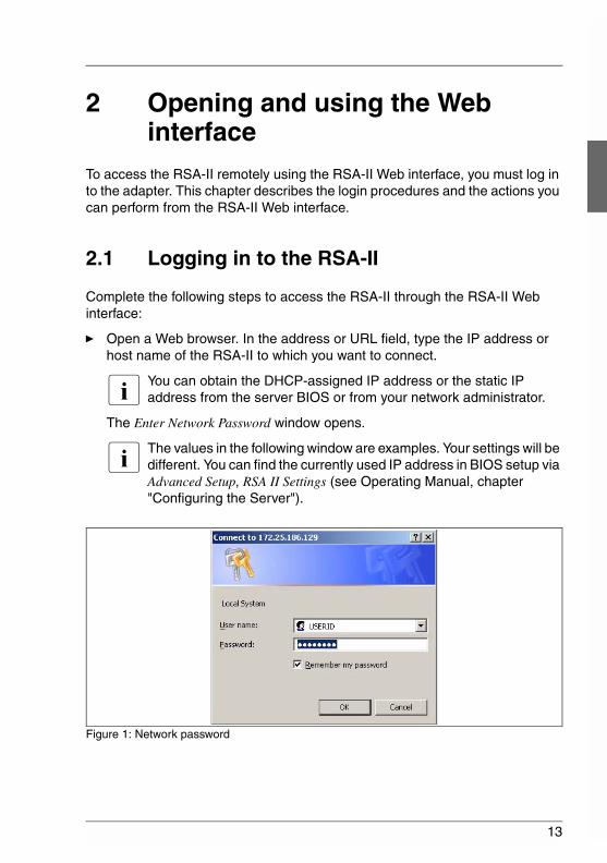
Ê Open a Web browser. In the address or URL field, type the IP address or host name of the RSA-II to which you want to connect.
I You can obtain the DHCP-assigned IP address or the static IP address from the server BIOS or from your network administrator.
The Enter Network Password window opens.
I The values in the following window are examples. Your settings will be different. You can find the currently used IP address in BIOS setup via Advanced Setup, RSA II Settings (see Operating Manual, chapter "Configuring the Server").
Figure 1: Network password
14
Logging in to the RSA-II Opening and using the Web interface
© c
ogni
tas.
Ges
ells
chft
für
Tech
nik-
Dok
umen
tatio
n m
bH 2
006
Pfa
d: D
:\Akt
uelle
s_P
roje
kt\P
RIM
ER
GY
\RX
800S
3\rs
a-rx
800s
2-s3
_us\
RS
A_e
.k02
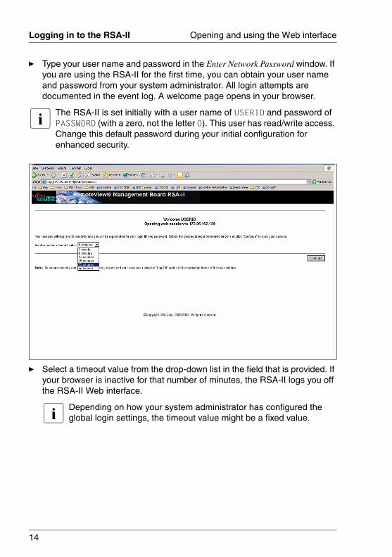
Ê Type your user name and password in the Enter Network Password window. If you are using the RSA-II for the first time, you can obtain your user name and password from your system administrator. All login attempts are documented in the event log. A welcome page opens in your browser.
I The RSA-II is set initially with a user name of USERID and password of PASSW0RD (with a zero, not the letter O). This user has read/write access. Change this default password during your initial configuration for enhanced security.
Ê Select a timeout value from the drop-down list in the field that is provided. If your browser is inactive for that number of minutes, the RSA-II logs you off the RSA-II Web interface.
I Depending on how your system administrator has configured the global login settings, the timeout value might be a fixed value.
15
Opening and using the Web interface Logging in to the RSA-II
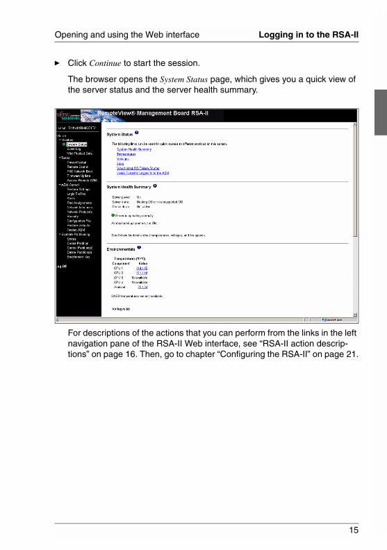
Ê Click Continue to start the session.
The browser opens the System Status page, which gives you a quick view of the server status and the server health summary.
For descriptions of the actions that you can perform from the links in the left navigation pane of the RSA-II Web interface, see “RSA-II action descrip-tions” on page 16. Then, go to chapter “Configuring the RSA-II” on page 21.
16
RSA-II action descriptions Opening and using the Web interface
© c
ogni
tas.
Ges
ells
chft
für
Tech
nik-
Dok
umen
tatio
n m
bH 2
006
Pfa
d: D
:\Akt
uelle
s_P
roje
kt\P
RIM
ER
GY
\RX
800S
3\rs
a-rx
800s
2-s3
_us\
RS
A_e
.k02
2.2 RSA-II action descriptions
The following table lists the actions that are available when you are logged in to the RSA-II.
Link Action Description
System Status View system health for a server, view the operating-system-failure screen capture, and view the users who are logged in to the RSA-II
You can monitor the server power and state and the temperature, voltage, and fan status of your server on the System Health Summary page. You can also view the image of the last operating-system-failure screen capture and the users who are logged in to the RSA-II.
Event Log View event logs for remote servers
The Event Log page contains entries that are currently stored in the server event log and power-on self-test (POST) event log. Information about all remote access attempts and dial-out events are recorded in the event log. All events in the log are time stamped using the RSA-II date and time settings. Some events will also generate alerts, if configured to do so on the Alerts page. You can sort and filter events in the event log.
Vital Product Data
View the server VPD
When the server starts, the RSA-II collects system information, basic input/output system (BIOS) information, and server component vital product data (VPD) and stores it in nonvolatile memory. This data is available from the Vital Product Data page.
Table 2: RSA-II actions
17
Opening and using the Web interface RSA-II action descriptions
Power/Restart Remotely turn on or restart a server
The RSA-II provides full remote power control over your server with power-on, power-off, and restart actions. In addition, power-on and restart statistics are captured and displayed to show server hardware availability.
Remote Control Redirect the server video console and use your computer disk drive or disk image as a drive on the server
From the Remote Control page, you can start the Remote Control function. Using the Remote Control function, you can redirect the server console to your computer, and you can mount one of your computer disk drives, such as the CD-ROM drive or the diskette drive, on the server. When you have redirected the server console, you can use your mouse and keyboard to control the server. When you have mounted a disk, you can use it to restart the server and to update firmware on the server. You can use the Remote Console function to access the mounted disk, which will appear as a Universal Serial Bus (USB) disk drive that is attached to the server.
PXE Network Boot
Change the host server startup (boot) sequence for the next restart to attempt a PXE/DHCP network startup.
If your server BIOS and Preboot Execution Environment (PXE) boot agent utility are properly defined, from the PXE Network Boot page you can change the host server startup (boot) sequence for the next restart to attempt a PXE/DHCP network startup. The host startup sequence will be altered only if the host is not under Privileged Access Protection (PAP). After the next restart occurs, the check box on the PXE Network Boot page will be cleared.
Firmware Update
Update firmware on the RSA-II
Use the options on the Firmware Update page to update firmware of the RSA-II.
Link Action Description
Table 2: RSA-II actions
18
RSA-II action descriptions Opening and using the Web interface
© c
ogni
tas.
Ges
ells
chft
für
Tech
nik-
Dok
umen
tatio
n m
bH 2
006
Pfa
d: D
:\Akt
uelle
s_P
roje
kt\P
RIM
ER
GY
\RX
800S
3\rs
a-rx
800s
2-s3
_us\
RS
A_e
.k02
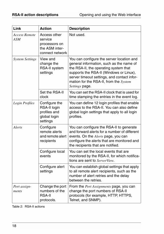
Access Remote ASM
Access other service processors on the ASM inter-connect network
Not used.
System Settings View and change the RSA-II system settings
You can configure the server location and general information, such as the name of the RSA-II, the operating system that supports the RSA-II (Windows or Linux), server timeout settings, and contact infor-mation for the RSA-II, from the System Settings page.
Set the RSA-II clock
You can set the RSA-II clock that is used for time stamping the entries in the event log.
Login Profiles Configure the RSA-II login profiles and global login settings
You can define 12 login profiles that enable access to the RSA-II. You can also define global login settings that apply to all login profiles.
Alerts Configure remote alerts and remote alert recipients
You can configure the RSA-II to generate and forward alerts for a number of different events. On the Alerts page, you can configure the alerts that are monitored and the recipients that are notified.
Configure local events
You can set the local events that are monitored by the RSA-II, for which notifica-tions are sent to ServerView.
Configure alert settings
You can establish global settings that apply to all remote alert recipients, such as the number of alert retries and the delay between the retries.
Port assign-ments
Change the port numbers of the RSA-II protocols.
From the Port Assignments page, you can change the port numbers of RSA-II protocols (for example, HTTP, HTTPS, Telnet, and SNMP).
Link Action Description
Table 2: RSA-II actions
19
Opening and using the Web interface RSA-II action descriptions
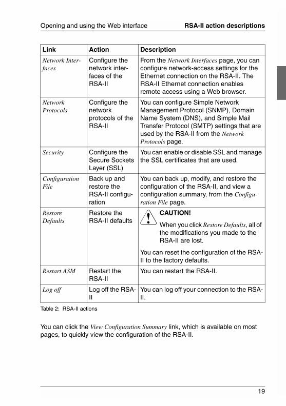
You can click the View Configuration Summary link, which is available on most pages, to quickly view the configuration of the RSA-II.
Network Inter-faces
Configure the network inter-faces of the RSA-II
From the Network Interfaces page, you can configure network-access settings for the Ethernet connection on the RSA-II. The RSA-II Ethernet connection enables remote access using a Web browser.
Network Protocols
Configure the network protocols of the RSA-II
You can configure Simple Network Management Protocol (SNMP), Domain Name System (DNS), and Simple Mail Transfer Protocol (SMTP) settings that are used by the RSA-II from the Network Protocols page.
Security Configure the Secure Sockets Layer (SSL)
You can enable or disable SSL and manage the SSL certificates that are used.
Configuration File
Back up and restore the RSA-II configu-ration
You can back up, modify, and restore the configuration of the RSA-II, and view a configuration summary, from the Configu-ration File page.
Restore Defaults
Restore the RSA-II defaults
V CAUTION!
When you click Restore Defaults, all of the modifications you made to the RSA-II are lost.
You can reset the configuration of the RSA-II to the factory defaults.
Restart ASM Restart the RSA-II
You can restart the RSA-II.
Log off Log off the RSA-II
You can log off your connection to the RSA-II.
Link Action Description
Table 2: RSA-II actions

21
3 Configuring the RSA-IIUse the links under ASM Control in the navigation pane to configure the RSA-II.
● From the System Settings page, you can:
– Set system information
– Select the operating system to support (Microsoft Windows or Linux)
I For the RSA-II to function correctly, the specified operating system must match the operating system of the server in which the RSA-II is installed.
– Select Linux before installing RSA-II software for Linux operating systems.
– Select Other before installing RSA-II software for Microsoft Windows and Novell Netware operating systems.
– Set server timeouts
– Set ASM date and time
● From the Login Profiles page, you can:
– Set login profiles to control access to the RSA-II
– Configure global login settings, such as the lockout period after unsuc-cessful login attempts
● From the Alerts page, you can:
– Configure remote alert recipients
– Set the number of remote alert attempts
– Select the delay between alerts
– Select which alerts will be sent
● From the Port Assignments page, you can change the port numbers of RSA-II services.
22
Configuring the RSA-II
© c
ogni
tas.
Ges
ells
chft
für
Tech
nik-
Dok
umen
tatio
n m
bH 2
006
Pfa
d: D
:\Akt
uelle
s_P
roje
kt\P
RIM
ER
GY
\RX
800S
3\rs
a-rx
800s
2-s3
_us\
RS
A_e
.k03
● From the Network Interfaces page, you can:
– Set up the Ethernet connection for the RSA-II
● From the Network Protocols page, you can:
– Configure SNMP setup
– Configure DNS setup
– Configure SMTP setup
● From the Security page, you can install and configure the Secure Sockets Layer (SSL) settings.
● From the Configuration File page, you can back up, modify, and restore the configuration of the RSA-II.
● From the Restore Defaults page, you can reset the RSA-II configuration to the factory defaults.
● From the Restart ASM page, you can restart the RSA-II.
23
Configuring the RSA-II Setting system information
3.1 Setting system information
Complete the following steps to set your RSA-II system information:
Ê Log in to the RSA-II where you want to set the system information. For more information, see chapter “Opening and using the Web interface” on page 13.
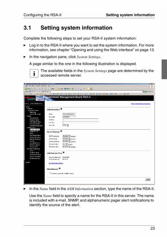
Ê In the navigation pane, click System Settings.
A page similar to the one in the following illustration is displayed.
I The available fields in the System Settings page are determined by the accessed remote server.
Ê In the Name field in the ASM Information section, type the name of the RSA-II.
Use the Name field to specify a name for the RSA-II in this server. The name is included with e-mail, SNMP, and alphanumeric pager alert notifications to identify the source of the alert.
24
Setting system information Configuring the RSA-II
© c
ogni
tas.
Ges
ells
chft
für
Tech
nik-
Dok
umen
tatio
n m
bH 2
006
Pfa
d: D
:\Akt
uelle
s_P
roje
kt\P
RIM
ER
GY
\RX
800S
3\rs
a-rx
800s
2-s3
_us\
RS
A_e
.k03
I – If you plan to set up an SMTP server for e-mail alert notifications, make sure that the name in the Name field is valid as part of an e-mail address (for example that there are no spaces).
– Your RSA-II name (in the Name field) and the IP host name of the RSA-II (in the Host Name field on the Network Interfaces page) do not automatically share the same name because the ASM Name field is limited to 15 characters. The Host Name field can contain up to 63 characters. To minimize confusion, set the ASM Name field to the nonqualified portion of the IP host name. The nonqualified IP host name consists of up to the first period of a fully qualified IP host name. For example, for the fully qualified IP host name asmcard1.us.company.com, the nonqualified IP host name is asmcard1. For information about your host name, see section “Configuring an Ethernet connection to the RSA-II” on page 49.
Ê In the ID number field, assign the RSA-II a unique identification number.
Ê In the Contact field, type the contact information. For example, you can specify the name and phone number of the person to contact if there is a problem with this server. You can type a maximum of 47 characters in this field.
Ê In the Location field, type the location of the server. Include in this field suffi-cient detail to quickly locate the server for maintenance or other purposes. You can type a maximum of 47 characters in this field.
Ê In the HOST O/S menu, click the type of operating system that is running on the server.
I For the RSA-II to function correctly, the specified operating system must match the operating system of the server in which the RSA-II is installed.– Select Linux before installing RSA-II software for Linux operating
systems.– Select Other before installing RSA-II software for Microsoft
Windows and Novell Netware operating systems.
Ê Scroll to the bottom of the page and click Save.
25
Configuring the RSA-II Setting system information
3.1.1 Setting server timeouts
Complete the following steps to set your server timeout values:
Ê Log in to the RSA-II where you want to set the server timeouts. For more information, see chapter “Opening and using the Web interface” on page 13.
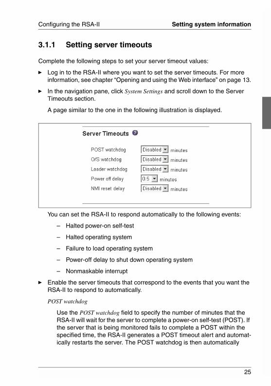
Ê In the navigation pane, click System Settings and scroll down to the Server Timeouts section.
A page similar to the one in the following illustration is displayed.
You can set the RSA-II to respond automatically to the following events:
– Halted power-on self-test
– Halted operating system
– Failure to load operating system
– Power-off delay to shut down operating system
– Nonmaskable interrupt
Ê Enable the server timeouts that correspond to the events that you want the RSA-II to respond to automatically.
POST watchdog
Use the POST watchdog field to specify the number of minutes that the RSA-II will wait for the server to complete a power-on self-test (POST). If the server that is being monitored fails to complete a POST within the specified time, the RSA-II generates a POST timeout alert and automat-ically restarts the server. The POST watchdog is then automatically

26
Setting system information Configuring the RSA-II
© c
ogni
tas.
Ges
ells
chft
für
Tech
nik-
Dok
umen
tatio
n m
bH 2
006
Pfa
d: D
:\Akt
uelle
s_P
roje
kt\P
RIM
ER
GY
\RX
800S
3\rs
a-rx
800s
2-s3
_us\
RS
A_e
.k03
disabled until the operating system is shut down and the server is power cycled (or until the operating system starts and the software is success-fully loaded).
I Power cycling means that the server is turned off and then immediately turned on.
To set the POST timeout value, select a number from the menu. To turn off this option, select Disabled.
I The POST watchdog requires a specially constructed POST routine that is available only on specific FSC servers. If this routine does not exist on your server, all settings in this field are ignored.
O/S watchdog
Use the O/S watchdog field to specify the number of minutes between checks of the operating system by the RSA-II. If the operating system fails to respond to one of these checks, the RSA-II generates an O/S timeout alert and restarts the server. After the server is restarted, the O/S watchdog is disabled until the operating system is shut down and the server is power cycled.
To set the O/S watchdog value, select a time interval from the menu. To turn off this watchdog, select Disabled. To capture operating-system-failure screens, you must enable the watchdog in the O/S watchdog field and select the O/S Time-out check box in the Remote Alerts section of the Remote Alerts page.
I – The O/S watchdog feature requires that the RSA-II software be installed on the server. For information about installing this software, see the RSA-II Installation Guide.
– If the O/S Time-out check box is selected in the Remote Alerts section of the Remote Alerts page, the RSA-II will attempt to send an alert to all configured remote alert recipients.
Loader watchdog
Use the Loader watchdog field to specify the number of minutes that the RSA-II waits between the completion of POST and the starting of the operating system. If this interval is exceeded, the RSA-II generates a loader timeout alert and automatically restarts the server. After the server is restarted, the loader timeout is automatically disabled until the operating system is shut down and the server is power cycled (or until the operating system starts and the software is successfully loaded).
27
Configuring the RSA-II Setting system information
To set the loader timeout value, select the time limit that the RSA-II will wait for the operating-system startup to be completed. To turn off this watchdog, select Disabled.
I – Before you start (boot) an operating system that does not have the RSA-II software installed (this can also include using a flash update diskette), make sure to select Disabled in the Loader watchdog field to prevent an unwanted restart of your server.
– If the Loader Time-out check box is selected in the Remote Alerts section of the Alerts page, the RSA-II will send an alert to all configured remote alert recipients.
Power off delay
V CAUTION!
Read the following information to prevent the loss of data or damage to data when you perform a remote shutdown of your operating system:
If the Windows 2000, Windows Server 2003, Red Hat Linux, SUSE LINUX, or Novell NetWare operating system is installed on your server, you have to install only the RSA-II software to support remote operating-system shutdown.
I If the value in the Power off delay field is less than 45 seconds, the RSA-II software will adjust the value to 45 seconds when it is loaded. You can decrease the power-off delay value after the server has started, but the RSA-II software will reset it to 45 seconds on the next server restart. The RSA-II software will not change a power-off delay value that is 45 seconds or greater.
Use the Power off delay field to specify the number of minutes that the RSA-II will wait for the operating system to shut down before turning off the server.
Shut down your server to determine how long it takes to shut down. Add a time buffer to that value and use it as your power-off delay setting to ensure that the operating system has time for an orderly shutdown before power is removed from the server.
To set the power-off delay value, select the time from the menu.
NMI reset delay
28
Setting system information Configuring the RSA-II
© c
ogni
tas.
Ges
ells
chft
für
Tech
nik-
Dok
umen
tatio
n m
bH 2
006
Pfa
d: D
:\Akt
uelle
s_P
roje
kt\P
RIM
ER
GY
\RX
800S
3\rs
a-rx
800s
2-s3
_us\
RS
A_e
.k03
Use the NMI reset delay field to specify the length of time, in minutes, that the RSA-II waits to automatically restart the server after a nonmaskable interrupt (NMI) is triggered. A nonmaskable interrupt usually indicates a critical error such as a hardware fault. A nonmaskable interrupt usually signals a parity error in the memory subsystem.
To disable the automatic server restart after a nonmaskable interrupt, select Disabled.
Ê Scroll to the bottom of the page and click Save.
3.1.2 Setting the date and time
The RSA-II contains its own real-time clock to time stamp all events that are logged in the event log. Alerts that are sent by e-mail, LAN, and SNMP use the real-time clock setting to time stamp the alerts. The clock settings support Greenwich mean time (GMT) offsets and daylight saving time (DST) for added ease-of-use for administrators who are managing systems remotely over different time zones. You can remotely access the event log even if the server is turned off or disabled. This facilitates immediate problem determination and resolution.
Complete the following steps to verify the date and time settings of the RSA-II:
Ê Log in to the RSA-II where you want to set the ASM date and time values. For more information, see chapter “Opening and using the Web interface” on page 13.
Ê In the navigation pane, click System Settings and scroll down to the ASM Date and Time section, which shows the date and time when the Web page was generated.
Ê To override the date and time settings and to enable daylight saving time (DST) and Greenwich mean time (GMT), click Set ASM Date and Time.
A page similar to the one in the following illustration is displayed.
29
Configuring the RSA-II Setting system information
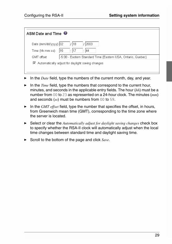
Ê In the Date field, type the numbers of the current month, day, and year.
Ê In the Time field, type the numbers that correspond to the current hour, minutes, and seconds in the applicable entry fields. The hour (hh) must be a number from 00 to 23 as represented on a 24-hour clock. The minutes (mm) and seconds (ss) must be numbers from 00 to 59.
Ê In the GMT offset field, type the number that specifies the offset, in hours, from Greenwich mean time (GMT), corresponding to the time zone where the server is located.
Ê Select or clear the Automatically adjust for daylight saving changes check box to specify whether the RSA-II clock will automatically adjust when the local time changes between standard time and daylight saving time.
Ê Scroll to the bottom of the page and click Save.
30
Creating a login profile Configuring the RSA-II
© c
ogni
tas.
Ges
ells
chft
für
Tech
nik-
Dok
umen
tatio
n m
bH 2
006
Pfa
d: D
:\Akt
uelle
s_P
roje
kt\P
RIM
ER
GY
\RX
800S
3\rs
a-rx
800s
2-s3
_us\
RS
A_e
.k03
3.2 Creating a login profile
Use the Login Profiles table to view, configure, or change individual login profiles. Use the links in the Login ID column to configure individual login profiles. You can define up to 12 unique profiles. Each link in the Login ID column is labeled with the configured login ID for that particular profile. If you have not configured a profile, the name of the link, by default, will be ~ not used ~.
Complete the following steps to configure a login profile:
Ê Log in to the RSA-II where you want to create a login profile. For more infor-mation, see chapter “Opening and using the Web interface” on page 13.
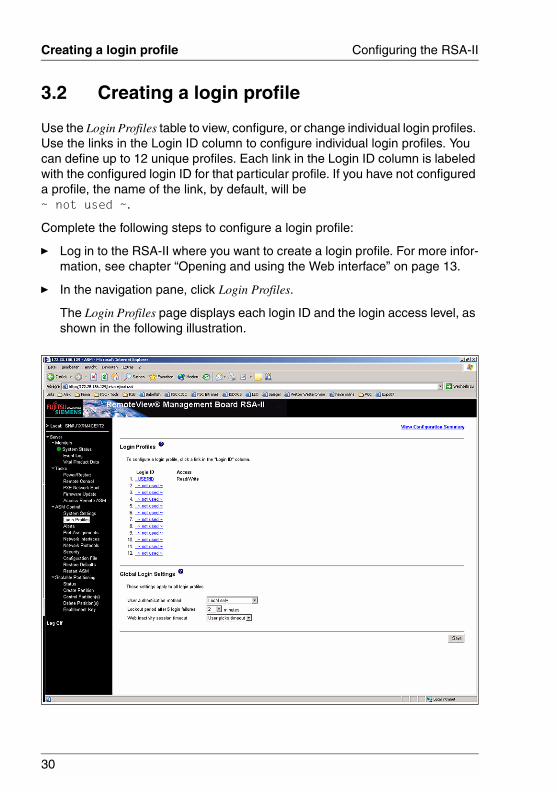
Ê In the navigation pane, click Login Profiles.
The Login Profiles page displays each login ID and the login access level, as shown in the following illustration.
31
Configuring the RSA-II Creating a login profile
I By default, the RSA-II is configured with one login profile that enables remote access using a login user ID of USERID and a password of PASSW0RD (the 0 is a zero, not the letter O). To avoid a potential security exposure, change this default login profile during the initial setup of the RSA-II.
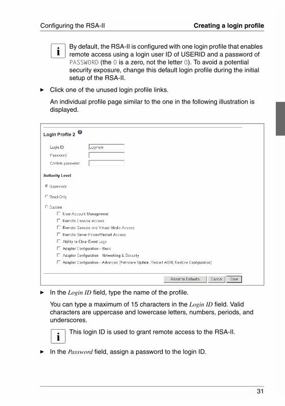
Ê Click one of the unused login profile links.
An individual profile page similar to the one in the following illustration is displayed.
Ê In the Login ID field, type the name of the profile.
You can type a maximum of 15 characters in the Login ID field. Valid characters are uppercase and lowercase letters, numbers, periods, and underscores.
I This login ID is used to grant remote access to the RSA-II.
Ê In the Password field, assign a password to the login ID.
32
Creating a login profile Configuring the RSA-II
© c
ogni
tas.
Ges
ells
chft
für
Tech
nik-
Dok
umen
tatio
n m
bH 2
006
Pfa
d: D
:\Akt
uelle
s_P
roje
kt\P
RIM
ER
GY
\RX
800S
3\rs
a-rx
800s
2-s3
_us\
RS
A_e
.k03
A password must contain at least five characters, one of which must be a nonalphabetic character. Null or empty passwords are accepted.
I This password is used with the login ID to grant remote access to the RSA-II.
Ê In the Confirm Password field, type the password again.
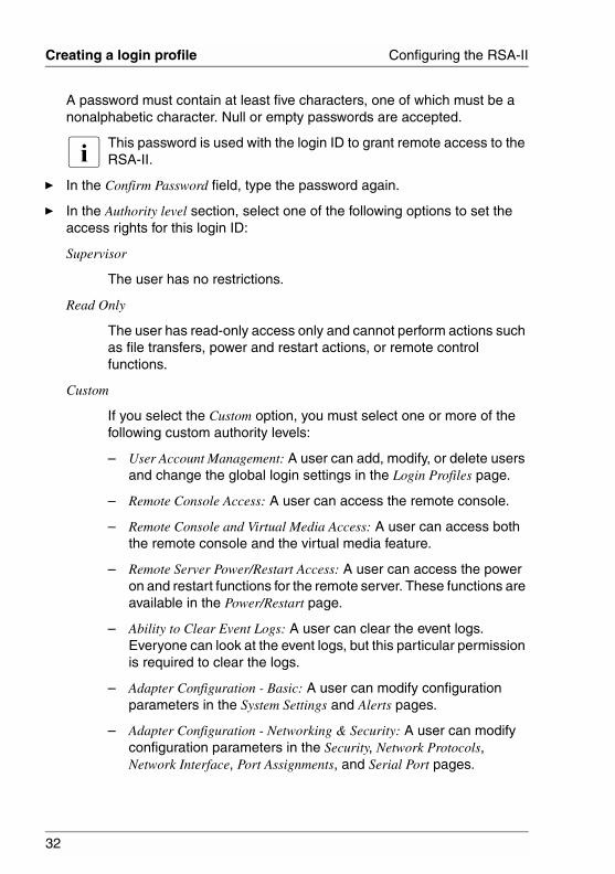
Ê In the Authority level section, select one of the following options to set the access rights for this login ID:
Supervisor
The user has no restrictions.
Read Only
The user has read-only access only and cannot perform actions such as file transfers, power and restart actions, or remote control functions.
Custom
If you select the Custom option, you must select one or more of the following custom authority levels:
– User Account Management: A user can add, modify, or delete users and change the global login settings in the Login Profiles page.
– Remote Console Access: A user can access the remote console.
– Remote Console and Virtual Media Access: A user can access both the remote console and the virtual media feature.
– Remote Server Power/Restart Access: A user can access the power on and restart functions for the remote server. These functions are available in the Power/Restart page.
– Ability to Clear Event Logs: A user can clear the event logs. Everyone can look at the event logs, but this particular permission is required to clear the logs.
– Adapter Configuration - Basic: A user can modify configuration parameters in the System Settings and Alerts pages.
– Adapter Configuration - Networking & Security: A user can modify configuration parameters in the Security, Network Protocols, Network Interface, Port Assignments, and Serial Port pages.
33
Configuring the RSA-II Creating a login profile
– Adapter Configuration (Advanced): A user has no restrictions when configuring the adapter. In addition, the user is said to have administrative access to the RSA-II, meaning that the user can also perform the following advanced functions: firmware updates, PXE network boot, restore adapter factory defaults, modify and restore adapter configuration from a configuration file, and restart and reset the adapter.
Ê Click Save to save your login ID settings.
34
Configuring the global login settings Configuring the RSA-II
© c
ogni
tas.
Ges
ells
chft
für
Tech
nik-
Dok
umen
tatio
n m
bH 2
006
Pfa
d: D
:\Akt
uelle
s_P
roje
kt\P
RIM
ER
GY
\RX
800S
3\rs
a-rx
800s
2-s3
_us\
RS
A_e
.k03
3.3 Configuring the global login settings
Complete the following steps to set conditions that apply to all login profiles for the RSA-II:
Ê Log in to the RSA-II for which you want to set the global login settings. For more information, see chapter “Opening and using the Web interface” on page 13.
Ê In the navigation pane, click Login Profiles.
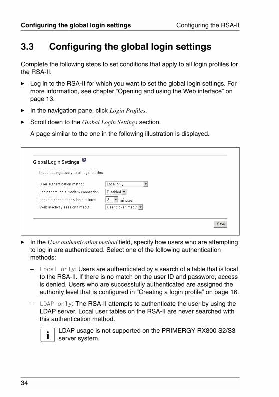
Ê Scroll down to the Global Login Settings section.
A page similar to the one in the following illustration is displayed.
Ê In the User authentication method field, specify how users who are attempting to log in are authenticated. Select one of the following authentication methods:
– Local only: Users are authenticated by a search of a table that is local to the RSA-II. If there is no match on the user ID and password, access is denied. Users who are successfully authenticated are assigned the authority level that is configured in “Creating a login profile” on page 16.
– LDAP only: The RSA-II attempts to authenticate the user by using the LDAP server. Local user tables on the RSA-II are never searched with this authentication method.
I LDAP usage is not supported on the PRIMERGY RX800 S2/S3 server system.
35
Configuring the RSA-II Configuring the global login settings
– Local first, then LDAP: Local authentication is attempted first. If local authentication fails, LDAP authentication is attempted.
I LDAP usage is not supported on the PRIMERGY RX800 S2/S3 server system.
– LDAP first, then Local: LDAP authentication is attempted first. If LDAP authentication fails, local authentication is attempted.
I LDAP usage is not supported on the PRIMERGY RX800 S2/S3 server system.
Ê In the Logins through a modem connection field, select Enabled to allow PPP users to dial in to the RSA-II through a modem connection.
I Serial port usage is not supported on the PRIMERGY RX800 S2/S3 server system. Therefore, PPP connections via modem are not possible.
Ê In the Lockout period after 5 login failures field, specify how long, in minutes, the RSA-II will prohibit remote login attempts, if more than five sequential failures to log in remotely are detected.
Ê In the Web inactivity session timeout field, specify how long, in minutes, the RSA-II will wait before disconnecting an inactive Web session. Select No timeout to disable this feature. Select User picks timeout if the user will select the timeout period during the login process.
Ê Click Save.
36
Configuring remote alert settings Configuring the RSA-II
© c
ogni
tas.
Ges
ells
chft
für
Tech
nik-
Dok
umen
tatio
n m
bH 2
006
Pfa
d: D
:\Akt
uelle
s_P
roje
kt\P
RIM
ER
GY
\RX
800S
3\rs
a-rx
800s
2-s3
_us\
RS
A_e
.k03
3.4 Configuring remote alert settings
You can configure remote alert recipients, the number of alert attempts, incidents that trigger remote alerts, and local alerts from the Alerts link on the navigation pane.
After you configure a remote alert recipient, the RSA-II will send an alert to that recipient. The alert is sent through a network connection, a numeric pager, or an alphanumeric pager when any event selected from the Monitored Alerts group occurs. This alert contains information about the nature of the event, the time and date of the event, and the name of the system that generated the alert.
The RSA-II offers alert redundancy for several managed systems at the same location. It sends alerts only once per connection type, even when there is more than one active LAN or serial connection. However, if one connection device fails, all other interconnected devices route the alerts to the next available connection.
I – If the SNMP Agent or SNMP Traps fields are not set to Enabled, no SNMP traps are sent. For information about these fields, see section “Configuring SNMP” on page 54.
– You cannot distinguish between the alerts that are sent to remote alert recipients. All configured recipients receive each alert selected.
3.4.1 Configuring remote alert recipients
You can define up to 12 unique remote alert recipients. Each link for an alert recipient is labeled with the recipient name, notification method, and alert status.
Complete the following steps to configure a remote alert recipient:
Ê Log in to the RSA-II for which you want to configure remote alert settings. For more information, see chapter “Opening and using the Web interface” on page 13.
Ê In the navigation pane, click Alerts.
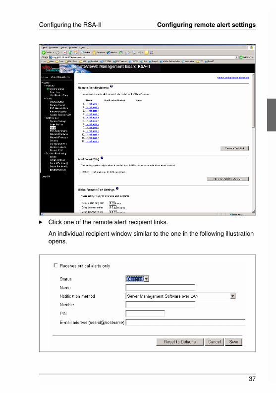
The Remote Alert Recipients page is displayed. You can see the notification method and alert status for each recipient, if they are set.
37
Configuring the RSA-II Configuring remote alert settings
Ê Click one of the remote alert recipient links.
An individual recipient window similar to the one in the following illustration opens.
38
Configuring remote alert settings Configuring the RSA-II
© c
ogni
tas.
Ges
ells
chft
für
Tech
nik-
Dok
umen
tatio
n m
bH 2
006
Pfa
d: D
:\Akt
uelle
s_P
roje
kt\P
RIM
ER
GY
\RX
800S
3\rs
a-rx
800s
2-s3
_us\
RS
A_e
.k03
Ê To have only critical alerts sent to the recipient, select the Receives critical alerts only check box.
Ê In the Status field, click Enabled to activate the remote alert recipient.
Ê In the Name field, type the name of the recipient or other identifier. The name that you type appears as the link for the recipient on the Alerts page.
Ê In the Notification method field, select the notification method for reaching the recipient. Select one of the following notification methods. Not all methods are available on all servers.
– Numeric pager
– SNMP over LAN
– E-mail over LAN
Ê In the Number field, type either the phone number, IP address, or host name at which to contact the recipient.
Type a phone number if you are using one of the following notification methods:
– Numeric pager (follow the phone number with a comma and the personal identification number [PIN])
– Alphanumeric pager
Ê Enter additional information for the selected notification method:
– If you selected the alphanumeric pager notification method, in the PIN field, enter the PIN.
– If you selected the E-mail over LAN notification method, in the E-Mail address field, type the e-mail address of the recipient.
I For the E-mail over LAN notification method to work correctly, configure the Simple Mail Transfer Protocol (SMTP) options on the Network Protocols page. For more information about SMTP options, see section “Configuring SMTP” on page 57.
39
Configuring the RSA-II Configuring remote alert settings
Ê In the PPP login ID field, specify the login ID or user ID that you need to log in to your Internet Service Provider (ISP).
I Serial port usage is not supported on the PRIMERGY RX800 S2/S3 server system. Therefore, PPP connections via modem are not possible.
Ê In the PPP password field, type the password that is used to log in to the ISP.
I Serial port usage is not supported on the PRIMERGY RX800 S2/S3 server system. Therefore, PPP connections via modem are not possible.
Ê Click Save to save your remote alert recipient profile.
Ê Repeat the procedure, starting from the second step on page 36 for each remote alert recipient profile.
Ê Click Generate Test Alert on the Remote Alert Recipients page to send a test alert to all configured remote alert recipients.
I All selected alert events are sent to all configured remote alert recipients.
3.4.2 Setting remote alert attempts
The remote alert attempts settings apply only to forwarded alerts.
Complete the following steps to set the number of times that the RSA-II attempts to send an alert:
Ê Log in to the RSA-II on which you want to set remote alert attempts. For more information, see chapter “Opening and using the Web interface” on page 13.
Ê In the navigation pane, click Alerts and scroll down to the Global Remote Alert Settings section (see below).
40
Configuring remote alert settings Configuring the RSA-II
© c
ogni
tas.
Ges
ells
chft
für
Tech
nik-
Dok
umen
tatio
n m
bH 2
006
Pfa
d: D
:\Akt
uelle
s_P
roje
kt\P
RIM
ER
GY
\RX
800S
3\rs
a-rx
800s
2-s3
_us\
RS
A_e
.k03
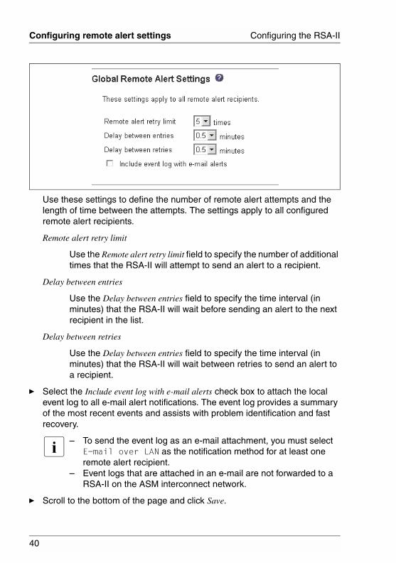
Use these settings to define the number of remote alert attempts and the length of time between the attempts. The settings apply to all configured remote alert recipients.
Remote alert retry limit
Use the Remote alert retry limit field to specify the number of additional times that the RSA-II will attempt to send an alert to a recipient.
Delay between entries
Use the Delay between entries field to specify the time interval (in minutes) that the RSA-II will wait before sending an alert to the next recipient in the list.
Delay between retries
Use the Delay between entries field to specify the time interval (in minutes) that the RSA-II will wait between retries to send an alert to a recipient.
Ê Select the Include event log with e-mail alerts check box to attach the local event log to all e-mail alert notifications. The event log provides a summary of the most recent events and assists with problem identification and fast recovery.
I – To send the event log as an e-mail attachment, you must select E-mail over LAN as the notification method for at least one remote alert recipient.
– Event logs that are attached in an e-mail are not forwarded to a RSA-II on the ASM interconnect network.
Ê Scroll to the bottom of the page and click Save.
41
Configuring the RSA-II Configuring remote alert settings
3.4.3 Setting remote alerts
Complete the following steps to select the remote alerts that are to be sent:
Ê Log in to the RSA-II where you want to set remote alerts. For more infor-mation, see chapter “Opening and using the Web interface” on page 13.
Ê In the navigation pane, click Alerts and scroll down to the Monitored Alerts section.
Ê Select the events that you want the RSA-II to monitor.
The remote alerts are categorized by the following levels of severity:
– Critical
– Warning
– System
All alerts are stored in the event log and sent to all configured remote alert recipients.
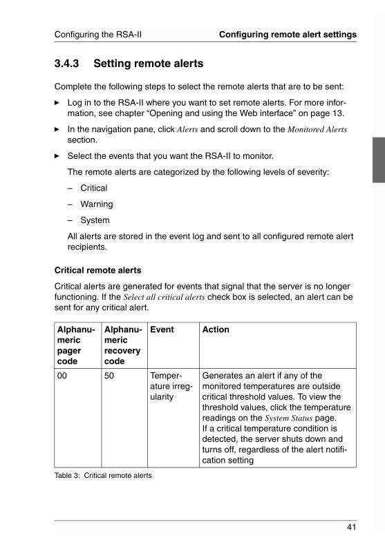
Critical remote alerts
Critical alerts are generated for events that signal that the server is no longer functioning. If the Select all critical alerts check box is selected, an alert can be sent for any critical alert.
Alphanu-meric pager code
Alphanu-meric recovery code
Event Action
00 50 Temper-ature irreg-ularity
Generates an alert if any of the monitored temperatures are outside critical threshold values. To view the threshold values, click the temperature readings on the System Status page. If a critical temperature condition is detected, the server shuts down and turns off, regardless of the alert notifi-cation setting
Table 3: Critical remote alerts
42
Configuring remote alert settings Configuring the RSA-II
© c
ogni
tas.
Ges
ells
chft
für
Tech
nik-
Dok
umen
tatio
n m
bH 2
006
Pfa
d: D
:\Akt
uelle
s_P
roje
kt\P
RIM
ER
GY
\RX
800S
3\rs
a-rx
800s
2-s3
_us\
RS
A_e
.k03
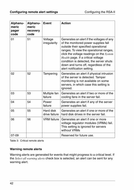
Warning remote alerts
Warning alerts are generated for events that might progress to a critical level. If the Select all warning alerts check box is selected, an alert can be sent for any warning alert.
01 51 Voltage irregularity
Generates an alert if the voltages of any of the monitored power supplies fall outside their specified operational ranges. To view the operational ranges, click the voltage readings on the System Health page. If a critical voltage condition is detected, the server shuts down and turns off, regardless of the alert notification setting.
02 52 Tampering Generates an alert if physical intrusion of the server is detected. Tamper monitoring is not available on some servers, in which case this setting is ignored.
03 53 Multiple fan failure
Generates an alert if two or more of the cooling fans in the server fail.
04 54 Power failure
Generates an alert if any of the server power supplies fail.
05 55 Hard disk drive failure
Generates an alert if one or more of the hard disk drives in the server fail.
06 56 VRM failure Generates an alert if one or more voltage regulator modules (VRMs) fail. This setting is ignored for servers without VRMs
07-09 Reserved for future use.
Alphanu-meric pager code
Alphanu-meric recovery code
Event Action
Table 3: Critical remote alerts
43
Configuring the RSA-II Configuring remote alert settings
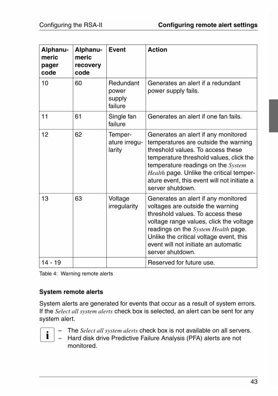
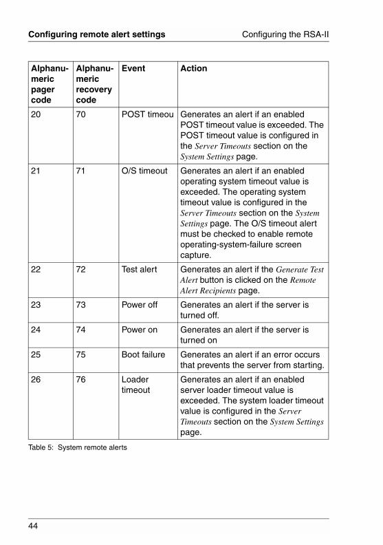
System remote alerts
System alerts are generated for events that occur as a result of system errors. If the Select all system alerts check box is selected, an alert can be sent for any system alert.
I – The Select all system alerts check box is not available on all servers.– Hard disk drive Predictive Failure Analysis (PFA) alerts are not
monitored.
Alphanu-meric pager code
Alphanu-meric recovery code
Event Action
10 60 Redundant power supply failure
Generates an alert if a redundant power supply fails.
11 61 Single fan failure
Generates an alert if one fan fails.
12 62 Temper-ature irregu-larity
Generates an alert if any monitored temperatures are outside the warning threshold values. To access these temperature threshold values, click the temperature readings on the System Health page. Unlike the critical temper-ature event, this event will not initiate a server shutdown.
13 63 Voltage irregularity
Generates an alert if any monitored voltages are outside the warning threshold values. To access these voltage range values, click the voltage readings on the System Health page. Unlike the critical voltage event, this event will not initiate an automatic server shutdown.
14 - 19 Reserved for future use.
Table 4: Warning remote alerts
44
Configuring remote alert settings Configuring the RSA-II
© c
ogni
tas.
Ges
ells
chft
für
Tech
nik-
Dok
umen
tatio
n m
bH 2
006
Pfa
d: D
:\Akt
uelle
s_P
roje
kt\P
RIM
ER
GY
\RX
800S
3\rs
a-rx
800s
2-s3
_us\
RS
A_e
.k03
Alphanu-meric pager code
Alphanu-meric recovery code
Event Action
20 70 POST timeou Generates an alert if an enabled POST timeout value is exceeded. The POST timeout value is configured in the Server Timeouts section on the System Settings page.
21 71 O/S timeout Generates an alert if an enabled operating system timeout value is exceeded. The operating system timeout value is configured in the Server Timeouts section on the System Settings page. The O/S timeout alert must be checked to enable remote operating-system-failure screen capture.
22 72 Test alert Generates an alert if the Generate Test Alert button is clicked on the Remote Alert Recipients page.
23 73 Power off Generates an alert if the server is turned off.
24 74 Power on Generates an alert if the server is turned on
25 75 Boot failure Generates an alert if an error occurs that prevents the server from starting.
26 76 Loader timeout
Generates an alert if an enabled server loader timeout value is exceeded. The system loader timeout value is configured in the Server Timeouts section on the System Settings page.
Table 5: System remote alerts

45
Configuring the RSA-II Configuring remote alert settings
Ê Scroll to the bottom of the page and click Save.
3.4.4 Setting local events
Complete the following steps to select the local events to which the RSA-II will respond:
Ê Log in to the RSA-II where you want to set local events. For more infor-mation, see chapter “Opening and using the Web interface” on page 13.
Ê In the navigation pane, click Alerts and scroll down to the Monitored Local Events section.
Ê Select the events that you want to store in the event log. The RSA-II stores the notification only in the event log.
27 77 PFA notifi-cation
Generates an alert if a PFA notification is generated by the server hardware. This feature is available only on servers that have PFA-enabled hardware.
28 - 29 Reserved for future use.
38 88 Partition configuration
Generates an alert if a partition config-uration notification is generated by the server. This feature is available only on servers that have partitionable hardware.
Alphanu-meric pager code
Alphanu-meric recovery code
Event Action
Alphanu-meric pager code
Alphanu-meric recovery code
Event Action
Table 5: System remote alerts
46
Configuring remote alert settings Configuring the RSA-II
© c
ogni
tas.
Ges
ells
chft
für
Tech
nik-
Dok
umen
tatio
n m
bH 2
006
Pfa
d: D
:\Akt
uelle
s_P
roje
kt\P
RIM
ER
GY
\RX
800S
3\rs
a-rx
800s
2-s3
_us\
RS
A_e
.k03
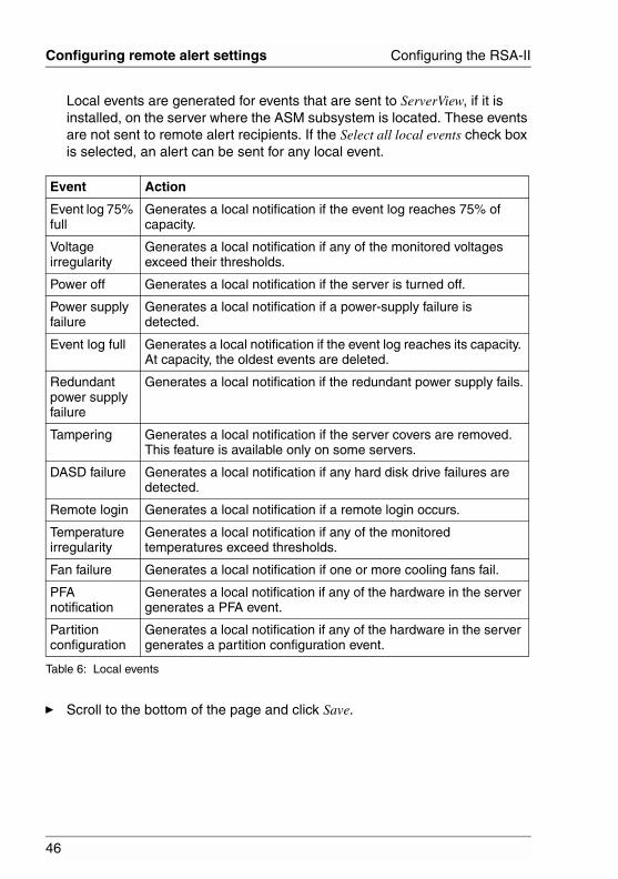
Local events are generated for events that are sent to ServerView, if it is installed, on the server where the ASM subsystem is located. These events are not sent to remote alert recipients. If the Select all local events check box is selected, an alert can be sent for any local event.
Ê Scroll to the bottom of the page and click Save.
Event Action
Event log 75% full
Generates a local notification if the event log reaches 75% of capacity.
Voltage irregularity
Generates a local notification if any of the monitored voltages exceed their thresholds.
Power off Generates a local notification if the server is turned off.
Power supply failure
Generates a local notification if a power-supply failure is detected.
Event log full Generates a local notification if the event log reaches its capacity. At capacity, the oldest events are deleted.
Redundant power supply failure
Generates a local notification if the redundant power supply fails.
Tampering Generates a local notification if the server covers are removed. This feature is available only on some servers.
DASD failure Generates a local notification if any hard disk drive failures are detected.
Remote login Generates a local notification if a remote login occurs.
Temperature irregularity
Generates a local notification if any of the monitored temperatures exceed thresholds.
Fan failure Generates a local notification if one or more cooling fans fail.
PFA notification
Generates a local notification if any of the hardware in the server generates a PFA event.
Partition configuration
Generates a local notification if any of the hardware in the server generates a partition configuration event.
Table 6: Local events
47
Configuring the RSA-II Configuring port assignments
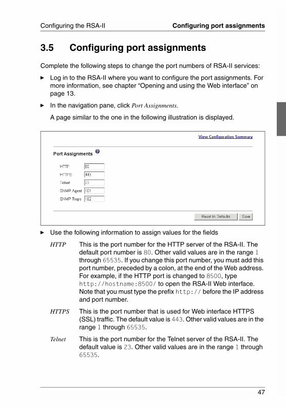
3.5 Configuring port assignments
Complete the following steps to change the port numbers of RSA-II services:
Ê Log in to the RSA-II where you want to configure the port assignments. For more information, see chapter “Opening and using the Web interface” on page 13.
Ê In the navigation pane, click Port Assignments.
A page similar to the one in the following illustration is displayed.
Ê Use the following information to assign values for the fields
HTTP This is the port number for the HTTP server of the RSA-II. The default port number is 80. Other valid values are in the range 1 through 65535. If you change this port number, you must add this port number, preceded by a colon, at the end of the Web address. For example, if the HTTP port is changed to 8500, type http://hostname:8500/ to open the RSA-II Web interface. Note that you must type the prefix http:// before the IP address and port number.
HTTPS This is the port number that is used for Web interface HTTPS (SSL) traffic. The default value is 443. Other valid values are in the range 1 through 65535.
Telnet This is the port number for the Telnet server of the RSA-II. The default value is 23. Other valid values are in the range 1 through 65535.
48
Configuring port assignments Configuring the RSA-II
© c
ogni
tas.
Ges
ells
chft
für
Tech
nik-
Dok
umen
tatio
n m
bH 2
006
Pfa
d: D
:\Akt
uelle
s_P
roje
kt\P
RIM
ER
GY
\RX
800S
3\rs
a-rx
800s
2-s3
_us\
RS
A_e
.k03
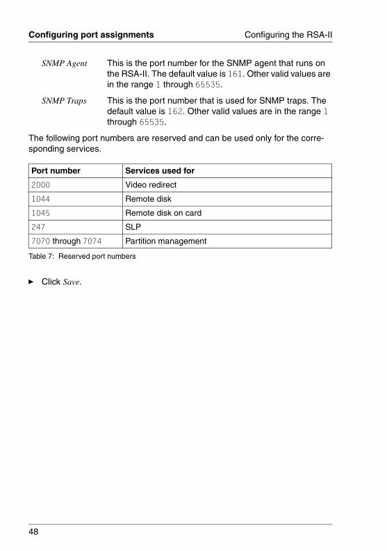
SNMP Agent This is the port number for the SNMP agent that runs on the RSA-II. The default value is 161. Other valid values are in the range 1 through 65535.
SNMP Traps This is the port number that is used for SNMP traps. The default value is 162. Other valid values are in the range 1 through 65535.
The following port numbers are reserved and can be used only for the corre-sponding services.
Ê Click Save.
Port number Services used for
2000 Video redirect
1044 Remote disk
1045 Remote disk on card
247 SLP
7070 through 7074 Partition management
Table 7: Reserved port numbers
49
Configuring the RSA-II Configuring an Ethernet connection to the RSA-II
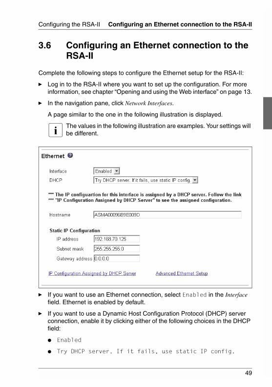
3.6 Configuring an Ethernet connection to the RSA-II
Complete the following steps to configure the Ethernet setup for the RSA-II:
Ê Log in to the RSA-II where you want to set up the configuration. For more information, see chapter “Opening and using the Web interface” on page 13.
Ê In the navigation pane, click Network Interfaces.
A page similar to the one in the following illustration is displayed.
I The values in the following illustration are examples. Your settings will be different.
Ê If you want to use an Ethernet connection, select Enabled in the Interface field. Ethernet is enabled by default.
Ê If you want to use a Dynamic Host Configuration Protocol (DHCP) server connection, enable it by clicking either of the following choices in the DHCP field:
● Enabled
● Try DHCP server. If it fails, use static IP config.
50
Configuring an Ethernet connection to the RSA-II Configuring the RSA-II
© c
ogni
tas.
Ges
ells
chft
für
Tech
nik-
Dok
umen
tatio
n m
bH 2
006
Pfa
d: D
:\Akt
uelle
s_P
roje
kt\P
RIM
ER
GY
\RX
800S
3\rs
a-rx
800s
2-s3
_us\
RS
A_e
.k03
The default setting is Try DHCP server. If it fails, use static IP config.
I Do not enable DHCP unless you have an accessible, active, and configured DHCP server on your network. When DHCP is used, the automatic configuration will override any manual settings.
If DHCP is enabled, the host name is assigned as follows:
● If the Hostname field contains an entry, the RSA-II DHCP support will request the DHCP server to use this host name.
● If the Hostname field does not contain an entry, the RSA-II DHCP support will request the DHCP server to assign a unique host name to the RSA-II.
If you enabled DHCP, follow the instructions after table “Advanced Ethernet setup” on page 52.
If you have not enabled DHCP, continue with the next step.
Ê Type the IP host name of the RSA-II in the Hostname field.
You can enter a maximum of 63 characters in this field, which represents the IP host name of the RSA-II. The host name defaults to ASMA, followed by the RSA-II burned-in media access control (MAC) address.
I The IP host name of the RSA-II (the Hostname field) and RSA-II name (the ASM Name field on the System page) do not automatically share the same name, because the ASM Name field is limited to 15 characters but the Hostname field can contain up to 63 characters. To minimize confusion, set the ASM Name field to the nonqualified portion of the IP host name. The nonqualified IP host name consists of up to the first period of a fully qualified IP host name. For example, for the fully qualified IP host name asmcard1.us.company.com, the nonqualified IP host name is asmcard1. For information about your host name, see section “Setting system information” on page 23.
Ê In the IP address field, type the IP address of the RSA-II. The IP address must contain four integers from 0 through 255 with no spaces and separated by periods.
Ê In the Subnet mask field, type the subnet mask that is used by the RSA-II. The subnet mask must contain four integers from 0 through 255 with no spaces or consecutive periods and separated by periods.
The default setting is 255.255.255.0.
51
Configuring the RSA-II Configuring an Ethernet connection to the RSA-II
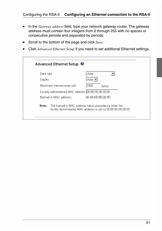
Ê In the Gateway address field, type your network gateway router. The gateway address must contain four integers from 0 through 255 with no spaces or consecutive periods and separated by periods.
Ê Scroll to the bottom of the page and click Save.
Ê Click Advanced Ethernet Setup if you need to set additional Ethernet settings.
52
Configuring an Ethernet connection to the RSA-II Configuring the RSA-II
© c
ogni
tas.
Ges
ells
chft
für
Tech
nik-
Dok
umen
tatio
n m
bH 2
006
Pfa
d: D
:\Akt
uelle
s_P
roje
kt\P
RIM
ER
GY
\RX
800S
3\rs
a-rx
800s
2-s3
_us\
RS
A_e
.k03
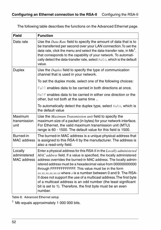
The following table describes the functions on the Advanced Ethernet page.
Field Function
Data rate Use the Data Rate field to specify the amount of data that is to be transferred per second over your LAN connection.To set the data rate, click the menu and select the data-transfer rate, in Mb1, that corresponds to the capability of your network. To automati-cally detect the data-transfer rate, select Auto, which is the default value.
1 Mb equals approximately 1 000 000 bits.
Duplex Use the Duplex field to specify the type of communication channel that is used in your network.
To set the duplex mode, select one of the following choices:
Full enables data to be carried in both directions at once.
Half enables data to be carried in either one direction or the other, but not both at the same time ..
To automatically detect the duplex type, select Auto, which is the default value
Maximum transmission unit
Use the Maximum Transmission unit field to specify the maximum size of a packet (in bytes) for your network interface. For Ethernet, the valid maximum transmission unit (MTU) range is 60 - 1500. The default value for this field is 1500.
Burned-in MAC address
The burned-in MAC address is a unique physical address that is assigned to this RSA-II by the manufacturer. The address is also a read-only field.
Locally administered MAC address
Enter a physical address for this RSA-II in the Locally administered MAC address field. If a value is specified, the locally administered address overrides the burned-in MAC address. The locally admin-istered address must be a hexadecimal value from 000000000000 through FFFFFFFFFFFF. This value must be in the form xx.xx.xx.xx.xx.xx where x is a number between 0 and 9. The RSA-II does not support the use of a multicast address.The first byte of a multicast address is an odd number (the least significant bit is set to 1). Therefore, the first byte must be an even number.
Table 8: Advanced Ethernet setup
53
Configuring the RSA-II Configuring an Ethernet connection to the RSA-II
Ê Modify the advanced Ethernet settings as necessary.
Ê Scroll to the bottom of the page and click Save.
Ê Click Back to return to the Network Interfaces page. If DHCP is enabled, the server automatically assigns the host name, IP address, gateway address, subnet mask, domain name, DHCP server IP address, and up to three DNS server IP addresses.
Ê If DHCP is enabled, to view the DHCP server assigned setting, click IP Configuration Assigned by DHCP Server.
Ê Click Save.
Ê In the navigation pane, click Restart ASM to activate the changes.
54
Configuring network protocols Configuring the RSA-II
© c
ogni
tas.
Ges
ells
chft
für
Tech
nik-
Dok
umen
tatio
n m
bH 2
006
Pfa
d: D
:\Akt
uelle
s_P
roje
kt\P
RIM
ER
GY
\RX
800S
3\rs
a-rx
800s
2-s3
_us\
RS
A_e
.k03
3.7 Configuring network protocols
On the Network Protocols page, you can perform the following functions:
● Configure Simple Network Management Protocol (SNMP)
● Configure Domain Name System (DNS)
● Configure Simple Mail Transfer Protocol (SMTP)
3.7.1 Configuring SNMP
You can query the SNMP agent to collect the sysgroup information and to send configured SNMP alerts to the configured host names or IP addresses.
I If you plan to configure Simple Network Management Protocol (SNMP) traps on the RSA-II, you must install and compile the management infor-mation base (MIB) on your SNMP manager. The MIB supports SNMP traps. The MIB is included in the RSA-II firmware update package.
Complete the following steps to configure SNMP:
Ê Log in to the RSA-II where you want to configure SNMP. For more infor-mation, see chapter “Opening and using the Web interface” on page 13.
Ê In the navigation pane, click System Settings.
Ê In the ASM information page that is displayed, specify system contact and system location information. For information about the System Settings page, see section “Setting system information” on page 23.
Ê Scroll to the bottom of the page and click Save.
Ê In the navigation pane, click Network Protocols.
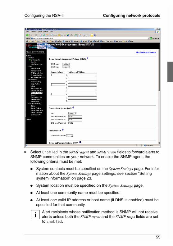
A page similar to the one in the following illustration is displayed.
55
Configuring the RSA-II Configuring network protocols
Ê Select Enabled in the SNMP agent and SNMP traps fields to forward alerts to SNMP communities on your network. To enable the SNMP agent, the following criteria must be met:
● System contacts must be specified on the System Settings page. For infor-mation about the System Settings page settings, see section “Setting system information” on page 23.
● System location must be specified on the System Settings page.
● At least one community name must be specified.
● At least one valid IP address or host name (if DNS is enabled) must be specified for that community.
I Alert recipients whose notification method is SNMP will not receive alerts unless both the SNMP agent and the SNMP traps fields are set to Enabled.
56
Configuring network protocols Configuring the RSA-II
© c
ogni
tas.
Ges
ells
chft
für
Tech
nik-
Dok
umen
tatio
n m
bH 2
006
Pfa
d: D
:\Akt
uelle
s_P
roje
kt\P
RIM
ER
GY
\RX
800S
3\rs
a-rx
800s
2-s3
_us\
RS
A_e
.k03
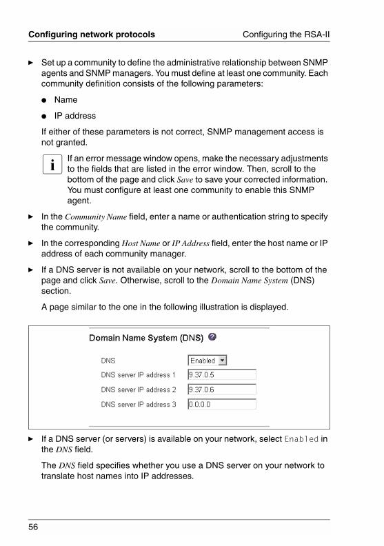
Ê Set up a community to define the administrative relationship between SNMP agents and SNMP managers. You must define at least one community. Each community definition consists of the following parameters:
● Name
● IP address
If either of these parameters is not correct, SNMP management access is not granted.
I If an error message window opens, make the necessary adjustments to the fields that are listed in the error window. Then, scroll to the bottom of the page and click Save to save your corrected information. You must configure at least one community to enable this SNMP agent.
Ê In the Community Name field, enter a name or authentication string to specify the community.
Ê In the corresponding Host Name or IP Address field, enter the host name or IP address of each community manager.
Ê If a DNS server is not available on your network, scroll to the bottom of the page and click Save. Otherwise, scroll to the Domain Name System (DNS) section.
A page similar to the one in the following illustration is displayed.
Ê If a DNS server (or servers) is available on your network, select Enabled in the DNS field.
The DNS field specifies whether you use a DNS server on your network to translate host names into IP addresses.
57
Configuring the RSA-II Configuring network protocols
Ê If you enabled DNS, in the DNS server IP address fields, specify the IP addresses of up to three DNS servers on your network. Each IP address must contain integers from 0 through 255 separated by periods.
Ê Scroll to the bottom of the page and click Save.
Ê In the navigation pane, click Restart ASM to activate the changes.
3.7.2 Configuring SMTP
Complete the following steps to specify the IP address or host name of the Simple Mail Transfer Protocol (SMTP) server.
I If you plan to set up an SMTP server for e-mail alert notifications, make sure that the name in the Name field in the ASM Information section of the System Settings window is valid as part of an e-mail address (for example, there are no spaces).
Ê Log in to the RSA-II where you want to configure SMTP. For more infor-mation, see chapter “Opening and using the Web interface” on page 13. In the navigation pane, click Network Protocols and scroll down to the SMTP section.
Ê In the SMTP Server Host Name or IP Address field, type the host name of the SMTP server. Use this field to specify the IP address or, if DNS is enabled and configured, the host name of the SMTP server.
Ê Scroll to the bottom of the page and click Save.
58
Configuring security Configuring the RSA-II
© c
ogni
tas.
Ges
ells
chft
für
Tech
nik-
Dok
umen
tatio
n m
bH 2
006
Pfa
d: D
:\Akt
uelle
s_P
roje
kt\P
RIM
ER
GY
\RX
800S
3\rs
a-rx
800s
2-s3
_us\
RS
A_e
.k03
3.8 Configuring security
Use the general procedure in this section to configure security for the RSA-II Web server and to configure security for the connection between the RSA-II and an LDAP server. If you are not familiar with the use of SSL certificates, read the information in “SSL certificate overview” on page 59.
I LDAP usage is not supported on the PRIMERGY RX800 S2/S3 server system. The corresponding sections are only included for the sake of completeness, as LDAP functions are shown on the Web site.
Use the following general tasks list to configure the security for the RSA-II:
Ê Configure the Secure Web server:
Ê Disable the SSL server. Use the SSL Server Configuration for Web Server section on the Security page.
Ê Generate or import a certificate. Use the SSL Server Certificate Management section on the Security page. (See section “SSL server certif-icate management” on page 59.)
Ê Enable the SSL server. Use the SSL Server Configuration for Web Server section on the Security page. (See section “Enabling SSL for the secure Web server” on page 68.)
Ê Configure SSL security for LDAP connections:
Ê Disable the SSL client. Use the SSL Client Configuration for LDAP Client section on the Security page.
Ê Generate or import a certificate. Use the SSL Client Certificate Management section on the Security page. (See section “SSL client certificate management” on page 68.)
Ê Import one or more trusted certificates. Use the SSL Client Trusted Certificate Management section on the Security page. (See section “SSL client trusted certificate management” on page 69.)
Ê Restart the RSA-II for SSL server configuration changes to take effect. For more information, see section “Restarting ASM” on page 77.
I Changes to the SSL client configuration take effect immediately and do not require a restart of the RSA-II.
59
Configuring the RSA-II Configuring security
3.8.1 SSL certificate overview
You can use SSL with either a self-signed certificate or with a certificate that is signed by a third-party certificate authority. Using a self-signed certificate is the simplest method for using SSL, but it does create a small security risk. The risk arises because the SSL client has no way of validating the identity of the SSL server for the first connection that is attempted between the client and server. It is possible that a third party could impersonate the server and intercept data that is flowing between the RSA-II and the Web browser. If, at the time of the initial connection between the browser and the RSA-II, the self-signed certif-icate is imported into the certificate store of the browser, all future communica-tions will be secure for that browser (assuming that the initial connection was not compromised by an attack).
For more complete security, you can use a certificate that is signed by a certif-icate authority. To obtain a signed certificate, use the SSL Certificate Management page to generate a certificate-signing request. You must then send the certificate-signing request to a certificate authority and make arrange-ments to procure a certificate. When the certificate is received, it is then imported into the RSA-II through the Import a Signed Certificate link, and you can enable SSL.
The function of the certificate authority is to verify the identity of the RSA-II. A certificate contains digital signatures for the certificate authority and the RSA-II. If a well-known certificate authority issues the certificate or if the certificate of the certificate authority has already been imported into the Web browser, the browser will be able to validate the certificate and positively identify the RSA-II Web server.
3.8.2 SSL server certificate management
The SSL server requires that a valid certificate and corresponding private encryption key be installed before SSL is enabled. Two methods are available for generating the private key and required certificate: using a self-signed certif-icate and using a certificate that is signed by a certificate authority. If you want to use a self-signed certificate for the SSL server, see“Generating a self-signed certificate” on page 60. If you want to use a certificate-authority-signed certif-icate for the SSL server, see “Generating a certificate-signing request” on page 62.
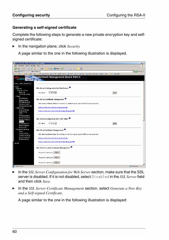
60
Configuring security Configuring the RSA-II
© c
ogni
tas.
Ges
ells
chft
für
Tech
nik-
Dok
umen
tatio
n m
bH 2
006
Pfa
d: D
:\Akt
uelle
s_P
roje
kt\P
RIM
ER
GY
\RX
800S
3\rs
a-rx
800s
2-s3
_us\
RS
A_e
.k03
Generating a self-signed certificate
Complete the following steps to generate a new private encryption key and self-signed certificate:
Ê In the navigation plane, click Security.
A page similar to the one in the following illustration is displayed.
Ê In the SSL Server Configuration for Web Server section, make sure that the SSL server is disabled. If it is not disabled, select Disabled in the SSL Server field and then click Save.
Ê In the SSL Server Certificate Management section, select Generate a New Key and a Self-signed Certificate.
A page similar to the one in the following illustration is displayed:
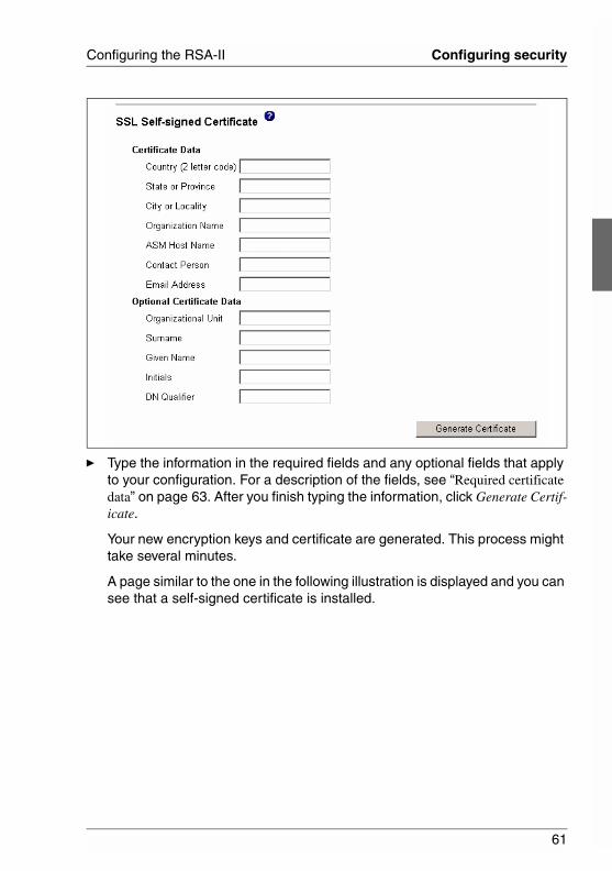
61
Configuring the RSA-II Configuring security
Ê Type the information in the required fields and any optional fields that apply to your configuration. For a description of the fields, see “Required certificate data” on page 63. After you finish typing the information, click Generate Certif-icate.
Your new encryption keys and certificate are generated. This process might take several minutes.
A page similar to the one in the following illustration is displayed and you can see that a self-signed certificate is installed.
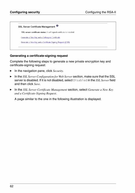
62
Configuring security Configuring the RSA-II
© c
ogni
tas.
Ges
ells
chft
für
Tech
nik-
Dok
umen
tatio
n m
bH 2
006
Pfa
d: D
:\Akt
uelle
s_P
roje
kt\P
RIM
ER
GY
\RX
800S
3\rs
a-rx
800s
2-s3
_us\
RS
A_e
.k03
Generating a certificate-signing request
Complete the following steps to generate a new private encryption key and certificate-signing request:
Ê In the navigation pane, click Security.
Ê In the SSL Server Configuration for Web Server section, make sure that the SSL server is disabled. If it is not disabled, select Disabled in the SSL Server field and then click Save.
Ê In the SSL Server Certificate Management section, select Generate a New Key and a Certificate-Signing Request.
A page similar to the one in the following illustration is displayed.
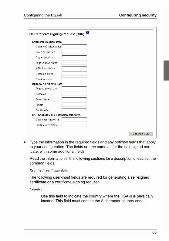
63
Configuring the RSA-II Configuring security
Ê Type the information in the required fields and any optional fields that apply to your configuration. The fields are the same as for the self-signed certif-icate, with some additional fields.
Read the information in the following sections for a description of each of the common fields.
Required certificate data
The following user-input fields are required for generating a self-signed certificate or a certificate-signing request.
Country
Use this field to indicate the country where the RSA-II is physically located. This field must contain the 2-character country code.
64
Configuring security Configuring the RSA-II
© c
ogni
tas.
Ges
ells
chft
für
Tech
nik-
Dok
umen
tatio
n m
bH 2
006
Pfa
d: D
:\Akt
uelle
s_P
roje
kt\P
RIM
ER
GY
\RX
800S
3\rs
a-rx
800s
2-s3
_us\
RS
A_e
.k03
State or Province
Use this field to indicate the state or province where the RSA-II is physically located. This field can contain a maximum of 30 characters.
City or Locality
Use this field to indicate the city or locality where the RSA-II is physi-cally located. This field can contain a maximum of 50 characters.
Organization Name
Use this field to indicate the company or organization that owns the RSA-II. When this is used to generate a certificate-signing request, the issuing certificate authority can verify that the organization that is requesting the certificate is legally entitled to claim ownership of the given company or organization name. This field can contain a maximum of 60 characters.
ASM Host Name
Use this field to indicate the RSA-II host name that currently appears in the browser Web address bar.
Make sure that the value that you typed in the ASM host name field exactly matches the host name as it is known by the Web browser. The browser compares the host name in the resolved Web address to the name that appears in the certificate. To prevent certificate warnings from the browser, the value that is used in this field must match the host name that is used by the browser to connect to the RSA-II. For example, if the address in the Web address bar is http://mm11.xyz.com/private/main.ssi, the value that is used for the ASM Host Name field must be mm11.xyz.com. If the Web address is http://mm11/private/main.ssi, the value that is used must be mm11. If the Web address is http://192.168.70.2/private/main.ssi, the value that is used must be 192.168.70.2.
This certificate attribute is generally referred to as the common name.
This field can contain a maximum of 60 characters.
65
Configuring the RSA-II Configuring security
Contact Person
Use this field to indicate the name of a contact person who is respon-sible for the RSA-II. This field can contain a maximum of 60 characters.
Email Address
Use this field to indicate the e-mail address of a contact person who is responsible for the RSA-II. This field can contain a maximum of 60 characters.
Optional certificate data
The following user-input fields are optional for generating a self-signed certificate or a certificate-signing request:
Organizational Unit
Use this field to indicate the unit within the company or organization that owns the RSA-II. This field can contain a maximum of 60 characters.
Surname
Use this field for additional information, such as the surname of a person who is responsible for the RSA-II. This field can contain a maximum of 60 characters
Given Name
Use this field for additional information, such as the given name of a person who is responsible for the RSA-II. This field can contain a maximum of 60 characters.
Initials
Use this field for additional information, such as the initials of a person who is responsible for the RSA-II. This field can contain a maximum of 20 characters.
DN Qualifier
Use this field for additional information, such as a distinguished name qualifier for the RSA-II. This field can contain a maximum of 60 characters.
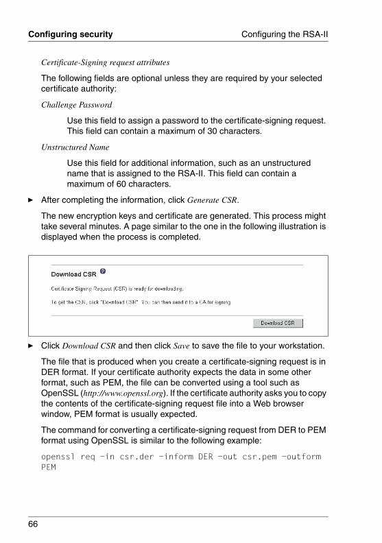
66
Configuring security Configuring the RSA-II
© c
ogni
tas.
Ges
ells
chft
für
Tech
nik-
Dok
umen
tatio
n m
bH 2
006
Pfa
d: D
:\Akt
uelle
s_P
roje
kt\P
RIM
ER
GY
\RX
800S
3\rs
a-rx
800s
2-s3
_us\
RS
A_e
.k03
Certificate-Signing request attributes
The following fields are optional unless they are required by your selected certificate authority:
Challenge Password
Use this field to assign a password to the certificate-signing request. This field can contain a maximum of 30 characters.
Unstructured Name
Use this field for additional information, such as an unstructured name that is assigned to the RSA-II. This field can contain a maximum of 60 characters.
Ê After completing the information, click Generate CSR.
The new encryption keys and certificate are generated. This process might take several minutes. A page similar to the one in the following illustration is displayed when the process is completed.
Ê Click Download CSR and then click Save to save the file to your workstation.
The file that is produced when you create a certificate-signing request is in DER format. If your certificate authority expects the data in some other format, such as PEM, the file can be converted using a tool such as OpenSSL (http://www.openssl.org). If the certificate authority asks you to copy the contents of the certificate-signing request file into a Web browser window, PEM format is usually expected.
The command for converting a certificate-signing request from DER to PEM format using OpenSSL is similar to the following example:
openssl req -in csr.der -inform DER -out csr.pem -outform PEM
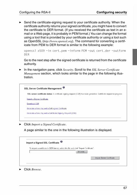
67
Configuring the RSA-II Configuring security
Ê Send the certificate-signing request to your certificate authority. When the certificate authority returns your signed certificate, you might have to convert the certificate to DER format. (If you received the certificate as text in an e-mail or a Web page, it is probably in PEM format.) You can change the format using a tool that is provided by your certificate authority or using a tool such as OpenSSL (http://www.openssl.org). The command for converting a certif-icate from PEM to DER format is similar to the following example:
openssl x509 -in cert.pem -inform PEM -out cert.der -outform DER
Go to the next step after the signed certificate is returned from the certificate authority.
Ê In the navigation pane, click Security. Scroll to the SSL Server Certificate Management section, which looks similar to the page in the following illus-tration.
Ê Click Import a Signed Certificate.
A page similar to the one in the following illustration is displayed.
Ê Click Browse.
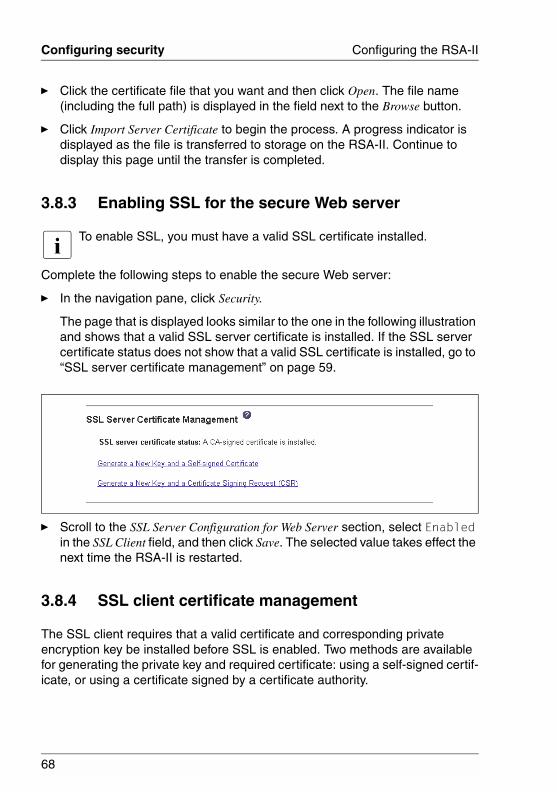
68
Configuring security Configuring the RSA-II
© c
ogni
tas.
Ges
ells
chft
für
Tech
nik-
Dok
umen
tatio
n m
bH 2
006
Pfa
d: D
:\Akt
uelle
s_P
roje
kt\P
RIM
ER
GY
\RX
800S
3\rs
a-rx
800s
2-s3
_us\
RS
A_e
.k03
Ê Click the certificate file that you want and then click Open. The file name (including the full path) is displayed in the field next to the Browse button.
Ê Click Import Server Certificate to begin the process. A progress indicator is displayed as the file is transferred to storage on the RSA-II. Continue to display this page until the transfer is completed.
3.8.3 Enabling SSL for the secure Web server
I To enable SSL, you must have a valid SSL certificate installed.
Complete the following steps to enable the secure Web server:
Ê In the navigation pane, click Security.
The page that is displayed looks similar to the one in the following illustration and shows that a valid SSL server certificate is installed. If the SSL server certificate status does not show that a valid SSL certificate is installed, go to “SSL server certificate management” on page 59.
Ê Scroll to the SSL Server Configuration for Web Server section, select Enabled in the SSL Client field, and then click Save. The selected value takes effect the next time the RSA-II is restarted.
3.8.4 SSL client certificate management
The SSL client requires that a valid certificate and corresponding private encryption key be installed before SSL is enabled. Two methods are available for generating the private key and required certificate: using a self-signed certif-icate, or using a certificate signed by a certificate authority.
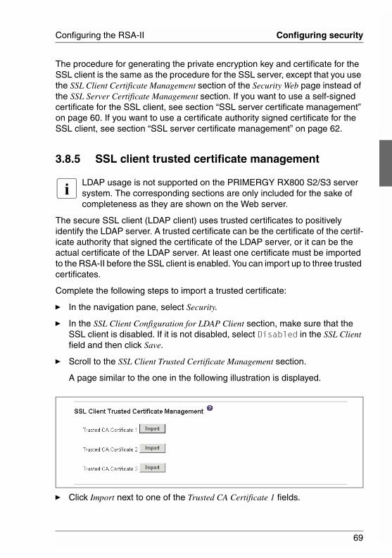
69
Configuring the RSA-II Configuring security
The procedure for generating the private encryption key and certificate for the SSL client is the same as the procedure for the SSL server, except that you use the SSL Client Certificate Management section of the Security Web page instead of the SSL Server Certificate Management section. If you want to use a self-signed certificate for the SSL client, see section “SSL server certificate management” on page 60. If you want to use a certificate authority signed certificate for the SSL client, see section “SSL server certificate management” on page 62.
3.8.5 SSL client trusted certificate management
I LDAP usage is not supported on the PRIMERGY RX800 S2/S3 server system. The corresponding sections are only included for the sake of completeness as they are shown on the Web server.
The secure SSL client (LDAP client) uses trusted certificates to positively identify the LDAP server. A trusted certificate can be the certificate of the certif-icate authority that signed the certificate of the LDAP server, or it can be the actual certificate of the LDAP server. At least one certificate must be imported to the RSA-II before the SSL client is enabled. You can import up to three trusted certificates.
Complete the following steps to import a trusted certificate:
Ê In the navigation pane, select Security.
Ê In the SSL Client Configuration for LDAP Client section, make sure that the SSL client is disabled. If it is not disabled, select Disabled in the SSL Client field and then click Save.
Ê Scroll to the SSL Client Trusted Certificate Management section.
A page similar to the one in the following illustration is displayed.
Ê Click Import next to one of the Trusted CA Certificate 1 fields.
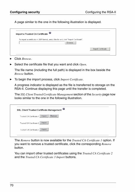
70
Configuring security Configuring the RSA-II
© c
ogni
tas.
Ges
ells
chft
für
Tech
nik-
Dok
umen
tatio
n m
bH 2
006
Pfa
d: D
:\Akt
uelle
s_P
roje
kt\P
RIM
ER
GY
\RX
800S
3\rs
a-rx
800s
2-s3
_us\
RS
A_e
.k03
A page similar to the one in the following illustration is displayed.
Ê Click Browse.
Ê Select the certificate file that you want and click Open.
The file name (including the full path) is displayed in the box beside the Browse button.
Ê To begin the import process, click Import Certificate.
A progress indicator is displayed as the file is transferred to storage on the RSA-II. Continue displaying this page until the transfer is completed.
The SSL Client Trusted Certificate Management section of the Security page now looks similar to the one in the following illustration.
The Remove button is now available for the Trusted CA Certificate 1 option. If you want to remove a trusted certificate, click the corresponding Remove button.
You can import other trusted certificates using the Trusted CA Certificate 2 and the Trusted CA Certificate 3 Import buttons.
71
Configuring the RSA-II Configuring the Secure Shell server
3.9 Configuring the Secure Shell server
I The Secure Shell server feature is not available on all servers.
The Secure Shell (SSH) feature provides secure access to the command-line interface and the serial (text console) redirect features of the RSA-II.
Secure Shell users are authenticated by exchanging user ID and password. The password and user ID are sent after the encryption channel is established. The user ID and password pair can be one of the 12 locally stored user IDs and passwords, or they can be stored on an LDAP server. Public key authentication is not supported.
I LDAP usage is not supported on the PRIMERGY RX800 S2/S3 server system.
3.9.1 Generating a Secure Shell server key
A Secure Shell server key is used to authenticate the identity of the Secure Shell server to the client. Secure shell must be disabled before you create a new Secure Shell server private key. You must create a server key before enabling the Secure Shell server.
When you request a new server key, both a Rivest, Shamir, and Adelman key and a DSA key are created to allow access to the RSA-II from either an SSH version 1.5 or an SSH version 2 client. For security, the Secure Shell server private key is not backed up during a configuration save and restore operation.
Complete the following steps to create a new Secure Shell server key:
Ê In the navigation pane, click Security.
Ê Scroll to the Secure Shell (SSH) Server section and make sure that the Secure Shell server is disabled.
Ê If it is not disabled, select Disabled in the SSH Server field and then click Save.
Ê Scroll to the SSH Server Key Management section.
A page similar to the one in the following illustration is displayed.
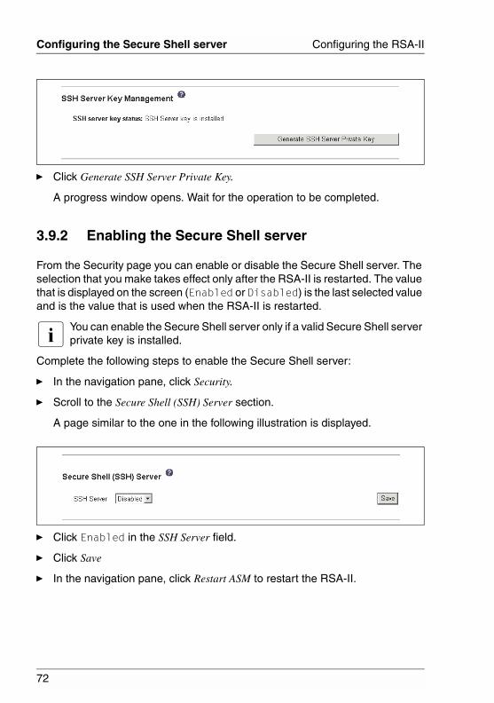
72
Configuring the Secure Shell server Configuring the RSA-II
© c
ogni
tas.
Ges
ells
chft
für
Tech
nik-
Dok
umen
tatio
n m
bH 2
006
Pfa
d: D
:\Akt
uelle
s_P
roje
kt\P
RIM
ER
GY
\RX
800S
3\rs
a-rx
800s
2-s3
_us\
RS
A_e
.k03
Ê Click Generate SSH Server Private Key.
A progress window opens. Wait for the operation to be completed.
3.9.2 Enabling the Secure Shell server
From the Security page you can enable or disable the Secure Shell server. The selection that you make takes effect only after the RSA-II is restarted. The value that is displayed on the screen (Enabled or Disabled) is the last selected value and is the value that is used when the RSA-II is restarted.
I You can enable the Secure Shell server only if a valid Secure Shell server private key is installed.
Complete the following steps to enable the Secure Shell server:
Ê In the navigation pane, click Security.
Ê Scroll to the Secure Shell (SSH) Server section.
A page similar to the one in the following illustration is displayed.
Ê Click Enabled in the SSH Server field.
Ê Click Save
Ê In the navigation pane, click Restart ASM to restart the RSA-II.
73
Configuring the RSA-II Configuring the Secure Shell server
3.9.3 Using the Secure Shell server
If you are using the Secure Shell client that is included in Red Hat Linux V7.3, to start a Secure Shell session to a RSA-II with network address 192.168.70.132, type a command similar to the following example:
ssh -x -l userid 192.168.70.132
where -x indicates "no X Window System forwarding" and -l indicates that the session should use the user ID userid.
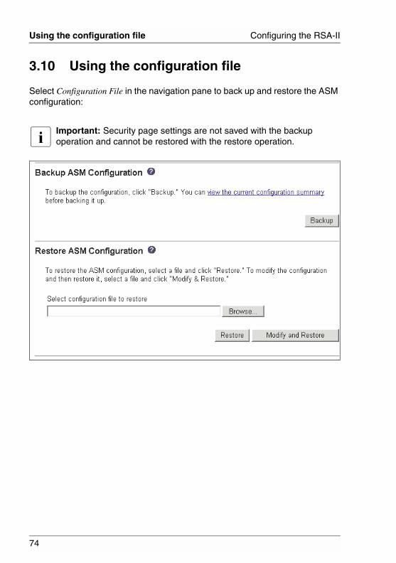
74
Using the configuration file Configuring the RSA-II
© c
ogni
tas.
Ges
ells
chft
für
Tech
nik-
Dok
umen
tatio
n m
bH 2
006
Pfa
d: D
:\Akt
uelle
s_P
roje
kt\P
RIM
ER
GY
\RX
800S
3\rs
a-rx
800s
2-s3
_us\
RS
A_e
.k03
3.10 Using the configuration file
Select Configuration File in the navigation pane to back up and restore the ASM configuration:
I Important: Security page settings are not saved with the backup operation and cannot be restored with the restore operation.
75
Configuring the RSA-II Using the configuration file
3.10.1 Backing up your current configuration
You can download a copy of your current ASM configuration to the client computer that is running the RSA-II Web interface. Use this backup copy to restore your RSA-II configuration if it is accidentally changed or damaged. Use it as a base that you can modify to configure multiple RSA-IIs with similar config-urations.
Complete the following steps to back up your current configuration:
Ê Log in to the RSA-II where you want to back up your current configuration. For more information, see chapter “Opening and using the Web interface” on page 13.
Ê In the navigation pane, click Configuration File.
Ê In the Backup ASM Configuration section, click view the current configuration summary.
Ê Verify the settings and then click Close.
Ê To back up this configuration, click Backup.
Ê Type a name for the backup, select the location where the file will be saved, and then click Save.
In Netscape Navigator, click Save File.
In Microsoft Internet Explorer, click Save this file to disk, then click OK.
3.10.2 Restoring and modifying your ASM configuration
You can restore a saved configuration in full, or you can modify key fields in the saved configuration before restoring the configuration to your RSA-II. By modifying the configuration file before restoring it, you can set up multiple RSA-IIs with similar configurations. You can quickly specify parameters that require unique values such as names and IP addresses, without having to enter common, shared information.
Complete the following steps to restore or modify your current configuration:
Ê Log in to the RSA-II where you want to restore the configuration. For more information, see chapter “Opening and using the Web interface” on page 13.
Ê In the navigation pane, click Configuration File.
Ê In the Restore ASM Configuration section, click Browse.
76
Using the configuration file Configuring the RSA-II
© c
ogni
tas.
Ges
ells
chft
für
Tech
nik-
Dok
umen
tatio
n m
bH 2
006
Pfa
d: D
:\Akt
uelle
s_P
roje
kt\P
RIM
ER
GY
\RX
800S
3\rs
a-rx
800s
2-s3
_us\
RS
A_e
.k03
Ê Click the configuration file that you want; then, click Open. The file (including the full path) appears in the box beside Browse.
Ê If you do not want to make changes to the configuration file, click Restore. A new window opens with the ASM configuration information. Make sure that this is the configuration that you want to restore. If it is not the correct config-uration, click Cancel.
If you want to make changes to the configuration file before restoring, click Modify and Restore to open an editable configuration summary window. Initially, only the fields that allow changes appear. To change between this view and the complete configuration summary view, click the Toggle View button at the top or bottom of the window. To modify the contents of a field, click the corresponding text box and enter the data.
I When you click Restore or Modify and Restore, an alert window might open if the configuration file that you are attempting to restore was created by a different type of service processor or was created by the same type of service processor with older firmware (and therefore, has less functionality). This alert message will include a list of system-management functions that you will have to configure after the restoration is complete. Some functions require configurations on more than one window.
Ê To continue restoring this file to the RSA-II, click Restore Configuration. A progress indicator appears as the firmware on the RSA-II is updated. A confirmation window opens to verify whether the update was successful.
I The security settings on the Security page are not restored by the restore operation.
Ê After receiving a confirmation that the restore process is complete, in the navigation pane, click Restart ASM; then, click Restart.
Ê Click OK to confirm that you want to restart your RSA-II.
Ê Click OK to close the current browser window.
Ê To log in to the RSA-II again, start your browser, and follow your regular login process.
77
Configuring the RSA-II Restarting ASM
3.11 Restoring ASM defaults
Use the Restore Defaults link to restore the default configuration of the RSA-II, if you have read/write access.
V CAUTION!
When you click Restore Defaults, you will lose all the modifications that you made to the RSA-II. You also will lose the remote control of the remote servers
Complete the following steps to restore the ASM defaults:
Ê Log in to the RSA-II. For more information, see chapter “Opening and using the Web interface” on page 13.
Ê In the navigation pane, click Restore Defaults to restore default settings of the RSA-II.
If this is a local system, your TCP/IP connection will be broken, and you must reconfigure the network interface to restore connectivity.
Ê Log in again to use the RSA-II Web interface.
Ê Reconfigure the network interface to restore connectivity. For information about the network interface, see section “Configuring an Ethernet connection to the RSA-II” on page 49.
3.12 Restarting ASM
Use the Restart ASM link to restart the RSA-II. You can perform this function only if you have read/write access. Any TCP/IP, modem, or interconnect connections are temporarily dropped. You must log in again to use the RSA-II Web interface.
Complete the following steps to restart the RSA-II or ISMP:
Ê In the navigation pane, click Restart ASM to restart a RSA-II or ISMP. Your TCP/IP or modem connections are broken.
Ê Log in again to use the RSA-II Web interface.
78
Logging off Configuring the RSA-II
© c
ogni
tas.
Ges
ells
chft
für
Tech
nik-
Dok
umen
tatio
n m
bH 2
006
Pfa
d: D
:\Akt
uelle
s_P
roje
kt\P
RIM
ER
GY
\RX
800S
3\rs
a-rx
800s
2-s3
_us\
RS
A_e
.k03
3.13 Logging off
Complete the following steps to log off the RSA-II or another remote server:
Ê In the navigation pane, click Log Off.
I If you are logged in to another remote server, you must first select Log Off Remote ASM.
Ê If you are running Internet Explorer or Netscape Navigator, click Yes in the confirmation window.
The current browser window closes to maintain security. You must manually close other open browser windows, if any, to prevent a cached version of your user ID and password from remaining available.
79
4 Monitoring remote server statusUse the links under the Monitors heading of the navigation pane to view the status of the server that you are accessing.
From the System Status pages, you can:
● Monitor the power status of the server and view the state of the operating system
● View the server temperature readings, voltage thresholds, and fan speeds
● View the latest server operating-system-failure screen capture
● View the list of users who are logged in to the RSA-II
From the Event Log page, you can:
● View certain Advanced System Management events that are recorded in the event log of the RSA-II
● View the severity of events
From the Vital Product Data (VPD) page, you can view the vital product data of the RSA-II, the server in which it is installed, and the ISMP.
4.1 Viewing system health
On the System Health Summary page, you can monitor the temperature readings, voltage thresholds, and fan status of your server.
Complete the following steps to view the system health and environmental infor-mation of the server:
Ê Log in to the RSA-II. For more information, see chapter “Opening and using the Web interface” on page 13.
Ê In the navigation pane, click System Status to view a dynamically-generated update of the overall health of the server.
A page similar to the one in the following illustration is displayed.
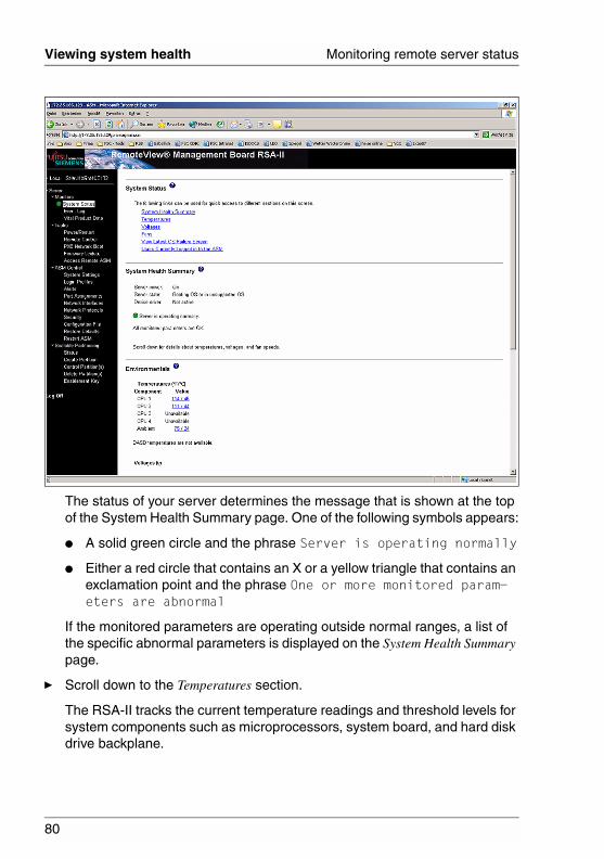
80
Viewing system health Monitoring remote server status
© c
ogni
tas.
Ges
ells
chft
für
Tech
nik-
Dok
umen
tatio
n m
bH 2
006
Pfa
d: D
:\Akt
uelle
s_P
roje
kt\P
RIM
ER
GY
\RX
800S
3\rs
a-rx
800s
2-s3
_us\
RS
A_e
.k04
The status of your server determines the message that is shown at the top of the System Health Summary page. One of the following symbols appears:
● A solid green circle and the phrase Server is operating normally
● Either a red circle that contains an X or a yellow triangle that contains an exclamation point and the phrase One or more monitored param-eters are abnormal
If the monitored parameters are operating outside normal ranges, a list of the specific abnormal parameters is displayed on the System Health Summary page.
Ê Scroll down to the Temperatures section.
The RSA-II tracks the current temperature readings and threshold levels for system components such as microprocessors, system board, and hard disk drive backplane.
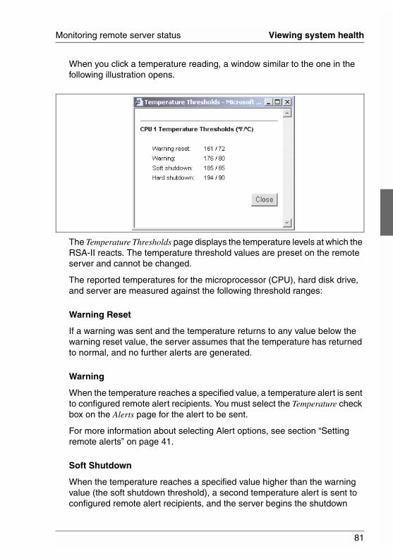
81
Monitoring remote server status Viewing system health
When you click a temperature reading, a window similar to the one in the following illustration opens.
The Temperature Thresholds page displays the temperature levels at which the RSA-II reacts. The temperature threshold values are preset on the remote server and cannot be changed.
The reported temperatures for the microprocessor (CPU), hard disk drive, and server are measured against the following threshold ranges:
Warning Reset
If a warning was sent and the temperature returns to any value below the warning reset value, the server assumes that the temperature has returned to normal, and no further alerts are generated.
Warning
When the temperature reaches a specified value, a temperature alert is sent to configured remote alert recipients. You must select the Temperature check box on the Alerts page for the alert to be sent.
For more information about selecting Alert options, see section “Setting remote alerts” on page 41.
Soft Shutdown
When the temperature reaches a specified value higher than the warning value (the soft shutdown threshold), a second temperature alert is sent to configured remote alert recipients, and the server begins the shutdown
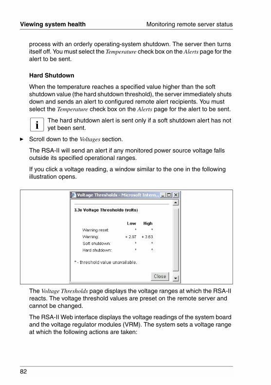
82
Viewing system health Monitoring remote server status
© c
ogni
tas.
Ges
ells
chft
für
Tech
nik-
Dok
umen
tatio
n m
bH 2
006
Pfa
d: D
:\Akt
uelle
s_P
roje
kt\P
RIM
ER
GY
\RX
800S
3\rs
a-rx
800s
2-s3
_us\
RS
A_e
.k04
process with an orderly operating-system shutdown. The server then turns itself off. You must select the Temperature check box on the Alerts page for the alert to be sent.
Hard Shutdown
When the temperature reaches a specified value higher than the soft shutdown value (the hard shutdown threshold), the server immediately shuts down and sends an alert to configured remote alert recipients. You must select the Temperature check box on the Alerts page for the alert to be sent.
I The hard shutdown alert is sent only if a soft shutdown alert has not yet been sent.
Ê Scroll down to the Voltages section.
The RSA-II will send an alert if any monitored power source voltage falls outside its specified operational ranges.
If you click a voltage reading, a window similar to the one in the following illustration opens.
The Voltage Thresholds page displays the voltage ranges at which the RSA-II reacts. The voltage threshold values are preset on the remote server and cannot be changed.
The RSA-II Web interface displays the voltage readings of the system board and the voltage regulator modules (VRM). The system sets a voltage range at which the following actions are taken:
83
Monitoring remote server status Viewing system health
Warning Reset
When the voltage drops below or exceeds the warning voltage range and then recovers to that range, the server assumes that the voltage has returned to normal, and no further alerts are generated.
Warning
When the voltage drops below or exceeds a specified voltage range, a voltage alert is sent to configured remote alert recipients. You must select the Voltage check box on the Alerts page for the alert to be sent.
Soft Shutdown
When the voltage drops below or exceeds a specified voltage range, a voltage alert is sent to configured remote alert recipients, and the server begins the shutdown process with an orderly operating-system shutdown. The server then turns itself off. You must select the Voltage check box on the Alerts page for the alert to be sent.
Hard Shutdown
When the voltage drops below or exceeds a specified voltage range, the server immediately shuts down and sends an alert to configured remote alert recipients. You must select the Voltage check box on the Alerts page for the alert to be sent.
I The hard shutdown alert is sent only if a soft shutdown alert has not yet been sent.
Ê Scroll down to the Fan Speeds section.
The RSA-II Web interface displays the running speed of the server fans (expressed in a percentage of the maximum fan speed). You receive a fan alert (Multiple Fan Failure or Single Fan Failure) when the fan speeds drop to an unacceptable level or the fans stop. You must select the Fan check box on the Alerts page for the alert to be sent.
Ê Scroll down to the Display Latest OS Failure Screen section. Click View OS Failure Screen to access an image of the operating-system-failure screen that was captured when the server stopped functioning.
I – To capture operating-system-failure screens, you must enable the OS Watchdog feature as described in section “Setting server timeouts” on page 25.

84
Viewing system health Monitoring remote server status
© c
ogni
tas.
Ges
ells
chft
für
Tech
nik-
Dok
umen
tatio
n m
bH 2
006
Pfa
d: D
:\Akt
uelle
s_P
roje
kt\P
RIM
ER
GY
\RX
800S
3\rs
a-rx
800s
2-s3
_us\
RS
A_e
.k04
– The operating-system-failure screen capture is available only if a supported operating system is installed on the server.
If an operating-system-failure screen event occurs while the operating system is running but then the server operating system stops running, the operating-system timeout is triggered, which causes the RSA-II to capture the operating-system-failure screen data and store it. The operating-system-failure screen image shows the date and time of the capture. The image will not be overwritten during the next operating-system installation because the RSA-II does not capture the operating-system loader screen. Only error conditions are captured and maintained. The RSA-II stores only the most recent error event information, overwriting older information when a new error event occurs.
Complete the following steps to remotely access a server operating-system-failure screen image:
Ê Log in to the Remote Service Adapter. For more information, see chapter “Opening and using the Web interface” on page 13.
Ê In the navigation pane, click System Health, and then scroll down to the Display Latest OS Failure Screen section.
Ê Click View OS Failure Screen.
The operating-system-failure screen image is displayed on your screen.
Ê Scroll down to the Users Currently Logged in section.
The RSA-II Web interface displays the login ID and access method of each user logged in to the RSA-II.
85
Monitoring remote server status Viewing the event log
4.2 Viewing the event log
The Event Log page contains all entries that are currently stored in the server event log and POST event log of the remote managed server. Information about all remote access attempts is recorded in the RSA-II event log. You can view the event log for all of the servers on an ASM interconnect network. The RSA-II time stamps all events and logs them into the event log, sending out the following alerts, if configured to do so by the system administrator:
● Event log 75% full
● Event log full
The event log has a limited capacity. When that limit is reached, the older events are deleted in a first-in, first-out order.
You can sort and filter entries in the event log.
Complete the following steps to access and view the event log:
Ê Log in to the RSA-II. For more information, see chapter “Opening and using the Web interface” on page 13.
Ê In the navigation pane, click Event Log to view the recent history of events on the server.
A page similar to the one in the following illustration is displayed.
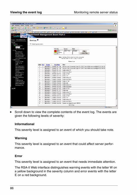
86
Viewing the event log Monitoring remote server status
© c
ogni
tas.
Ges
ells
chft
für
Tech
nik-
Dok
umen
tatio
n m
bH 2
006
Pfa
d: D
:\Akt
uelle
s_P
roje
kt\P
RIM
ER
GY
\RX
800S
3\rs
a-rx
800s
2-s3
_us\
RS
A_e
.k04
Ê Scroll down to view the complete contents of the event log. The events are given the following levels of severity:
Informational
This severity level is assigned to an event of which you should take note.
Warning
This severity level is assigned to an event that could affect server perfor-mance.
Error
This severity level is assigned to an event that needs immediate attention.
The RSA-II Web interface distinguishes warning events with the letter W on a yellow background in the severity column and error events with the letter E on a red background.
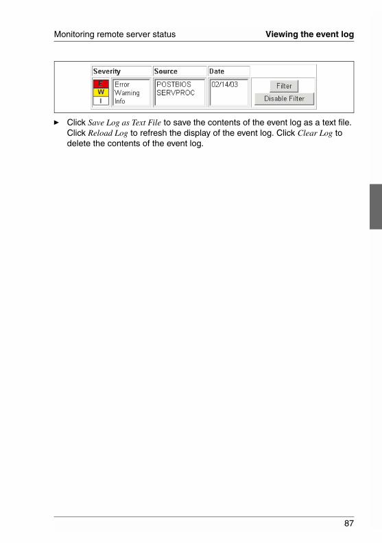
87
Monitoring remote server status Viewing the event log
Ê Click Save Log as Text File to save the contents of the event log as a text file. Click Reload Log to refresh the display of the event log. Click Clear Log to delete the contents of the event log.
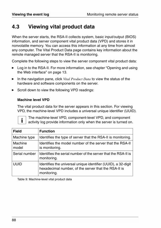
88
Viewing the event log Monitoring remote server status
© c
ogni
tas.
Ges
ells
chft
für
Tech
nik-
Dok
umen
tatio
n m
bH 2
006
Pfa
d: D
:\Akt
uelle
s_P
roje
kt\P
RIM
ER
GY
\RX
800S
3\rs
a-rx
800s
2-s3
_us\
RS
A_e
.k04
4.3 Viewing vital product data
When the server starts, the RSA-II collects system, basic input/output (BIOS) information, and server component vital product data (VPD) and stores it in nonvolatile memory. You can access this information at any time from almost any computer. The Vital Product Data page contains key information about the remote managed server that the RSA-II is monitoring.
Complete the following steps to view the server component vital product data:
Ê Log in to the RSA-II. For more information, see chapter “Opening and using the Web interface” on page 13.
Ê In the navigation pane, click Vital Product Data to view the status of the hardware and software components on the server.
Ê Scroll down to view the following VPD readings:
Machine level VPD
The vital product data for the server appears in this section. For viewing VPD, the machine-level VPD includes a universal unique identifier (UUID).
I The machine-level VPD, component-level VPD, and component activity log provide information only when the server is turned on.
Field Function
Machine type Identifies the type of server that the RSA-II is monitoring.
Machine model
Identifies the model number of the server that the RSA-II is monitoring.
Serial number Identifies the serial number of the server that the RSA-II is monitoring.
UUID Identifies the universal unique identifier (UUID), a 32-digit hexadecimal number, of the server that the RSA-II is monitoring.
Table 9: Machine-level vital product data
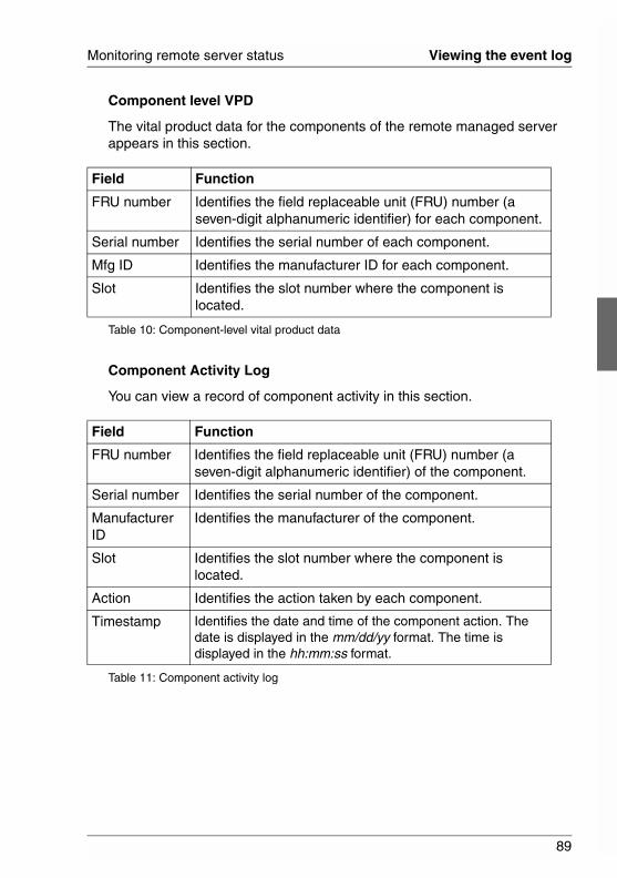
89
Monitoring remote server status Viewing the event log
Component level VPD
The vital product data for the components of the remote managed server appears in this section.
Component Activity Log
You can view a record of component activity in this section.
Field Function
FRU number Identifies the field replaceable unit (FRU) number (a seven-digit alphanumeric identifier) for each component.
Serial number Identifies the serial number of each component.
Mfg ID Identifies the manufacturer ID for each component.
Slot Identifies the slot number where the component is located.
Table 10: Component-level vital product data
Field Function
FRU number Identifies the field replaceable unit (FRU) number (a seven-digit alphanumeric identifier) of the component.
Serial number Identifies the serial number of the component.
Manufacturer ID
Identifies the manufacturer of the component.
Slot Identifies the slot number where the component is located.
Action Identifies the action taken by each component.
Timestamp Identifies the date and time of the component action. The date is displayed in the mm/dd/yy format. The time is displayed in the hh:mm:ss format.
Table 11: Component activity log
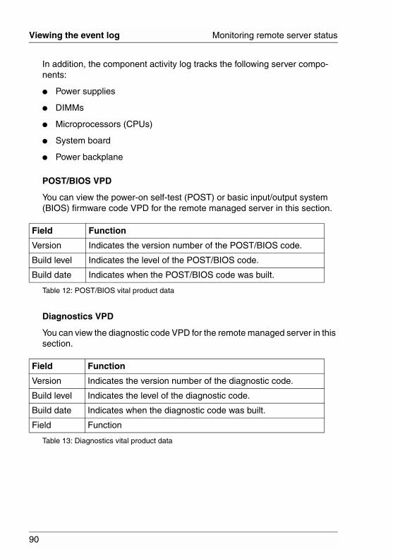
90
Viewing the event log Monitoring remote server status
© c
ogni
tas.
Ges
ells
chft
für
Tech
nik-
Dok
umen
tatio
n m
bH 2
006
Pfa
d: D
:\Akt
uelle
s_P
roje
kt\P
RIM
ER
GY
\RX
800S
3\rs
a-rx
800s
2-s3
_us\
RS
A_e
.k04
In addition, the component activity log tracks the following server compo-nents:
● Power supplies
● DIMMs
● Microprocessors (CPUs)
● System board
● Power backplane
POST/BIOS VPD
You can view the power-on self-test (POST) or basic input/output system (BIOS) firmware code VPD for the remote managed server in this section.
Diagnostics VPD
You can view the diagnostic code VPD for the remote managed server in this section.
Field Function
Version Indicates the version number of the POST/BIOS code.
Build level Indicates the level of the POST/BIOS code.
Build date Indicates when the POST/BIOS code was built.
Table 12: POST/BIOS vital product data
Field Function
Version Indicates the version number of the diagnostic code.
Build level Indicates the level of the diagnostic code.
Build date Indicates when the diagnostic code was built.
Field Function
Table 13: Diagnostics vital product data
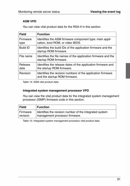
91
Monitoring remote server status Viewing the event log
ASM VPD
You can view vital product data for the RSA-II in this section.
Integrated system management processor VPD
You can view the vital product data for the integrated system management processor (ISMP) firmware code in this section.
Field Function
Firmware type
Identifies the ASM firmware component type: main appli-cation, boot ROM, or video BIOS.
Build ID Identifies the build IDs of the application firmware and the startup ROM firmware.
File name Identifies the file names of the application firmware and the startup ROM firmware.
Release date
Identifies the release dates of the application firmware and the startup ROM firmware.
Revision Identifies the revision numbers of the application firmware and the startup ROM firmware.
Table 14: ASM vital product data
Field Function
Firmware revision
Identifies the revision number of the integrated system management processor firmware.
Table 15: Integrated system management processor vital product data

93
5 Performing RSA-II tasksUse the functions under the Tasks heading in the navigation pane to directly control the actions of the RSA-II and your server. The tasks that you can perform depend on the server in which the RSA-II is installed.
You can perform the following tasks:
● View server power and restart activity
● Remotely control the power status of the server
● Remotely access the server console
● Remotely attach a disk or disk image to the server
● Update the RSA-II firmware
● Access other RSA-IIs
I Some features are available only on servers running a supported Microsoft Windows operating system.
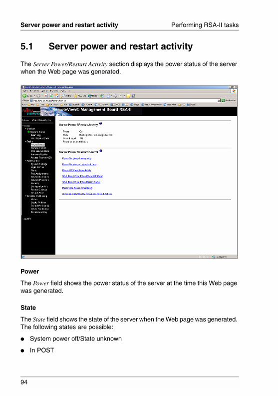
94
Server power and restart activity Performing RSA-II tasks
© c
ogni
tas.
Ges
ells
chft
für
Tech
nik-
Dok
umen
tatio
n m
bH 2
006
Pfa
d: D
:\Akt
uelle
s_P
roje
kt\P
RIM
ER
GY
\RX
800S
3\rs
a-rx
800s
2-s3
_us\
RS
A_e
.k05
5.1 Server power and restart activity
The Server Power/Restart Activity section displays the power status of the server when the Web page was generated.
Power
The Power field shows the power status of the server at the time this Web page was generated.
State
The State field shows the state of the server when the Web page was generated. The following states are possible:
● System power off/State unknown
● In POST
95
Performing RSA-II tasks Server power and restart activity
● Stopped in POST (Error detected)
● Booted Flash or System partition
● Booting OS or in unsupported OS (could be in the operating system if the operating system or application does not report the new system state)
● In OS
● CPUs held in reset
● System power on/Before POST
Restart count
The Restart count field shows the number of times that the server has been restarted.
I The counter is reset to zero each time the ASM subsystem is cleared to factory defaults.
Power-on hours
The Power-on hours field shows the total number of hours that the server has been turned on.
96
Remotely controlling the power status of a server Performing RSA-II tasks
© c
ogni
tas.
Ges
ells
chft
für
Tech
nik-
Dok
umen
tatio
n m
bH 2
006
Pfa
d: D
:\Akt
uelle
s_P
roje
kt\P
RIM
ER
GY
\RX
800S
3\rs
a-rx
800s
2-s3
_us\
RS
A_e
.k05
5.2 Remotely controlling the power status of a server
The RSA-II provides full remote power control over your server with power-on, power-off, and restart actions. In addition, power-on and restart statistics are captured and displayed to show server hardware availability.
V CAUTION!
Read the following information to prevent the loss of data or damage to data when you perform a remote shutdown of your operating system:
● If the Microsoft Windows 2000, Windows Server 2003, Red Hat Linux, SUSE LINUX, or Novell NetWare operating system is installed on your server, you to install the RSA-II software to support remote operating system shutdown.
● In the Power off delay field, if the value is less than 45 seconds, the RSA-II software will adjust the value to 45 seconds when it is loaded. You can decrease the power-off delay value after the server has started, but the RSA-II software will reset it to 45 seconds on the next server restart. The RSA-II software will not change a power-off delay value that is 45 seconds or greater.
I Select the following options only in case of an emergency, or if you are offsite and the server is nonresponsive.
Ê Log in to the RSA-II. For more information, see chapter “Opening and using the Web interface” on page 13.
Ê In the navigation pane, click Power/Restart. Scroll down to the Server Power/Restart Control section.
Ê Click one of the following options:
Power on server immediately
To turn on the server and start the operating system, click Power On Server Immediately.
Power on server at specified time
To turn on the server at a specified time and start the operating system, click Power on Server at Specified Time and set the time to turn on the server.
97
Performing RSA-II tasks Remotely controlling the power status of a server
Power off server immediately
To turn off the server without shutting down the operating system, click Power Off Server Immediately.
Shut down OS and then power off server
To shut down the operating system and then turn off the server, click Shutdown OS and then Power Off Server. This option requires that the RSA-II software be installed. You might also have to install FSC ServerView Agents.
Shut down OS and then restart server
To restart the operating system, click Shut down OS and then Restart Server. This option requires that the RSA-II software be installed. You might also have to install FSC ServerView Agents.
Restart the server immediately
To turn off and then turn on the server immediately without first shutting down the operating system, click Restart the Server Immediately.
Schedule Daily/Weekly Power and Restart Actions
To shut down the operating system, turn off the server at a specified daily or weekly time (with or without restarting the server), and turn on the server at a specified daily or weekly time, click Schedule Daily/Weekly Power and Restart Actions.
A confirmation message is displayed if you select any of these options, and you can cancel the operation if it was selected accidentally.
98
Remote control Performing RSA-II tasks
© c
ogni
tas.
Ges
ells
chft
für
Tech
nik-
Dok
umen
tatio
n m
bH 2
006
Pfa
d: D
:\Akt
uelle
s_P
roje
kt\P
RIM
ER
GY
\RX
800S
3\rs
a-rx
800s
2-s3
_us\
RS
A_e
.k05
5.3 Remote control
When you use the remote control function, you can view and interact with the server console, and you can assign to the server a CD-ROM drive, diskette drive, or disk image that is on your computer.
You must log in to the RSA-II with a user ID that has read/write access to use any of the remote control features.
5.3.1 Important information about updating your RSA-II firmware
I If you have updated the RSA-II firmware to the latest level or plan to in the future, read the following information.
The RSA-II uses a Java applet to perform many functions. When the RSA-II is updated to the latest firmware level, the Java applet is also updated to the latest level. By default, Java caches (stores locally) applets that were previously used. After a flash update of the RSA-II firmware, the Java applet that the server uses might not be at the latest level.
Complete the following steps to correct this problem:
Ê Click Start - Settings - Control Panel.
Ê Double-click Java Plug-in 1.4.
The Java Plug-in Control Panel window opens.
Ê Click the Cache tab.
Ê Choose one of the following options:
● Clear the Enable Caching check box. If you choose this option, Java caching is always disabled.
● Click Clear Caching. If you choose this option, you must click Clear Caching after each RSA-II firmware update.
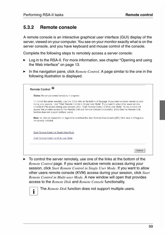
99
Performing RSA-II tasks Remote control
5.3.2 Remote console
A remote console is an interactive graphical user interface (GUI) display of the server, viewed on your computer. You see on your monitor exactly what is on the server console, and you have keyboard and mouse control of the console.
Complete the following steps to remotely access a server console:
Ê Log in to the RSA-II. For more information, see chapter “Opening and using the Web interface” on page 13.
Ê In the navigation pane, click Remote Control. A page similar to the one in the following illustration is displayed.
Ê To control the server remotely, use one of the links at the bottom of the Remote Control page. If you want exclusive remote access during your session, click Start Remote Control in Single User Mode. If you want to allow other users remote console (KVM) access during your session, click Start Remote Control in Multi-user Mode. A new window will open that provides access to the Remote Disk and Remote Console functionality.
I The Remote Disk function does not support multiple users.
100
Remote control Performing RSA-II tasks
© c
ogni
tas.
Ges
ells
chft
für
Tech
nik-
Dok
umen
tatio
n m
bH 2
006
Pfa
d: D
:\Akt
uelle
s_P
roje
kt\P
RIM
ER
GY
\RX
800S
3\rs
a-rx
800s
2-s3
_us\
RS
A_e
.k05
You can close the Remote Control window to disconnect from viewing the server console.
I – Do not close the Remote Control window if a remote disk is currently mounted. See page 104 for instructions for closing and unmounting a remote disk.
– If you have mouse or keyboard problems when using Remote Control, see the help that is available from the Remote Control page in the Web interface.
– If you use the remote console to change settings for the RSA-II in the server Configuration/Setup Utility program (Advanced Setup - RSA-II Settings), the server restarts the adapter and you lose the remote console and the login session. After a short delay, you can log in to the adapter again with a new session, start the remote console again, and exit the server Configuration/Setup Utility program.
5.3.3 Remote console keyboard support
The operating system on the client system that you are using will trap certain key combinations, such as Ctrl+Alt+Del in Microsoft Windows, instead of trans-mitting them to the server. Other keys, such as F1, might cause an action on your computer as well as on the server. Use the Remote Console Preferences link to create and edit customized buttons that can be used to send key strokes to the server.
Complete the following steps to create and edit customized buttons:
Ê In the Remote Disk area, click Preferences.
Ê Click the Key Buttons tab.
A window similar to the one in the following illustration opens.
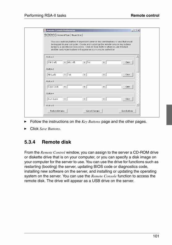
101
Performing RSA-II tasks Remote control
Ê Follow the instructions on the Key Buttons page and the other pages.
Ê Click Save Buttons.
5.3.4 Remote disk
From the Remote Control window, you can assign to the server a CD-ROM drive or diskette drive that is on your computer, or you can specify a disk image on your computer for the server to use. You can use the drive for functions such as restarting (booting) the server, updating BIOS code or diagnostics code, installing new software on the server, and installing or updating the operating system on the server. You can use the Remote Console function to access the remote disk. The drive will appear as a USB drive on the server.
102
Remote control Performing RSA-II tasks
© c
ogni
tas.
Ges
ells
chft
für
Tech
nik-
Dok
umen
tatio
n m
bH 2
006
Pfa
d: D
:\Akt
uelle
s_P
roje
kt\P
RIM
ER
GY
\RX
800S
3\rs
a-rx
800s
2-s3
_us\
RS
A_e
.k05
I – The following server operating systems have USB support, which is required for the Remote Disk feature:
● Microsoft Windows Server 2003
● Microsoft Windows 2000 with Service Pack 4 or later
● Red Hat Linux version 7.3
● SUSE LINUX version 8.0
● Novell NetWare 6.5
– The client system requires Microsoft Windows 2000 or later and the Java 1.4 Plug-in or later.
– The client system must have an Intel™ Pentium® III microprocessor or greater, operating at 700 MHz or faster, or equivalent.
Complete the following steps to assign a disk drive or disk image on your computer to the server:
Ê Log in to the RSA-II. For more information, see chapter “Opening and using the Web interface” on page 13.
Ê In the navigation pane, click Remote Control.
Ê In the Remote Control page, click one of the Start Remote Control options.
A page similar to the one in the following illustration is displayed.
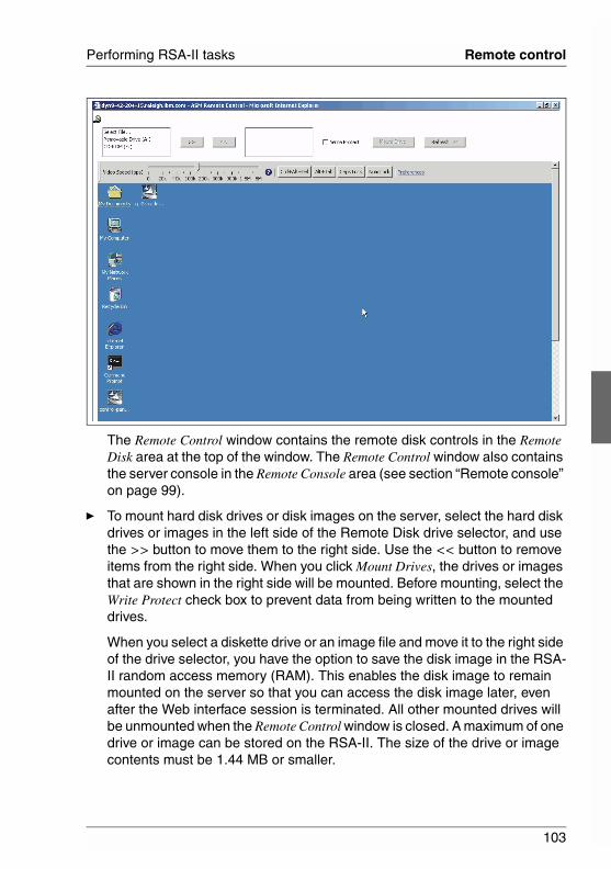
103
Performing RSA-II tasks Remote control
The Remote Control window contains the remote disk controls in the Remote Disk area at the top of the window. The Remote Control window also contains the server console in the Remote Console area (see section “Remote console” on page 99).
Ê To mount hard disk drives or disk images on the server, select the hard disk drives or images in the left side of the Remote Disk drive selector, and use the >> button to move them to the right side. Use the << button to remove items from the right side. When you click Mount Drives, the drives or images that are shown in the right side will be mounted. Before mounting, select the Write Protect check box to prevent data from being written to the mounted drives.
When you select a diskette drive or an image file and move it to the right side of the drive selector, you have the option to save the disk image in the RSA-II random access memory (RAM). This enables the disk image to remain mounted on the server so that you can access the disk image later, even after the Web interface session is terminated. All other mounted drives will be unmounted when the Remote Control window is closed. A maximum of one drive or image can be stored on the RSA-II. The size of the drive or image contents must be 1.44 MB or smaller.
104
Remote control Performing RSA-II tasks
© c
ogni
tas.
Ges
ells
chft
für
Tech
nik-
Dok
umen
tatio
n m
bH 2
006
Pfa
d: D
:\Akt
uelle
s_P
roje
kt\P
RIM
ER
GY
\RX
800S
3\rs
a-rx
800s
2-s3
_us\
RS
A_e
.k05
I Important: You will lose the disk image when the RSA-II is restarted or the RSA-II firmware is updated.
If the Encrypt disk and KVM data during transmission check box was selected before the Remote Control window was opened, the disk data is encrypted with 3DES encryption.
I The Encrypt disk and KVM date during transmission check box is not available on all servers.
To use the mounted disk, use the Remote Console function. The mounted disk will appear as a USB disk drive that is attached to the server.
Ê In the drop-down list in the Remote Disk section of the Remote Control window, click the item that you want. The choices are listed by the type of drive, followed by the volume label.
Select File
A disk image on your computer.
Removable Drive
A diskette drive on your computer.
CD-ROM
A CD-ROM drive on your computer.
Ê Click Mount Drive. If you clicked Select File in the previous step, browse to select the disk image file to use.
The drive or disk image will function as a USB device that is connected to the server.
To refresh the list of available drives on your computer, click Refresh List in the Remote Control window.
Ê When you have finished using the drive or disk image, close and unmount it. For Microsoft Windows, complete the following steps to close and unmount the drive or drive image.
Ê Double-click the Unplug or Eject Hardware icon in the Windows taskbar at the bottom right of the screen. If there is no icon, complete the following steps:
105
Performing RSA-II tasks Remote control
Ê In the Microsoft Windows Control Panel, click Add/Remove Hardware; then, click Next.
Ê Select Uninstall/Unplug a device; then, click Next.
Ê Click Unplug/Eject a device; then, click Next.
Ê Select USB Mass Storage Device and click Stop.
Ê Click Close.
Ê In the Remote Control window, click Unmount Drive.

106
Setting up PXE network boot Performing RSA-II tasks
© c
ogni
tas.
Ges
ells
chft
für
Tech
nik-
Dok
umen
tatio
n m
bH 2
006
Pfa
d: D
:\Akt
uelle
s_P
roje
kt\P
RIM
ER
GY
\RX
800S
3\rs
a-rx
800s
2-s3
_us\
RS
A_e
.k05
5.4 Setting up PXE network boot
I The PXE network boot feature is not available on all servers.
Complete the following steps to set up your server to attempt a Preboot Execution Environment (PXE) network boot at the next server restart:
Ê Log in to the RSA-II. For more information, see chapter “Opening and using the Web interface” on page 13.
Ê In the navigation pane, click PXE Network Boot.
A page similar to the one in the following illustration is displayed.
Ê Select the Attempt PXE network boot at next server restart check box.
Ê Click Save.
107
Performing RSA-II tasks Updating firmware
5.5 Updating firmware
Use the Firmware Update option on the navigation pane to update the firmware of the RSA-II.
I – To remotely update the firmware or operating system on the server, see section “Remote disk” on page 101.
– If you plan to use the Remote Control feature after you update the firmware, see section “Important information about updating your RSA-II firmware” on page 98.
Complete the following steps to update the startup or main application files of your RSA-II:
Ê Log in to the RSA-II. For more information, see chapter “Opening and using the Web interface” on page 13.
Ê In the navigation pane, click Firmware Update.
Ê Click Browse and navigate to the PKT or PKC file that you want to update.
I When you transfer (or flash) the main application packet, you must also flash the remote graphics packet separately.
Ê Click Open.
The file (including the full path) appears in the box beside Browse.
Ê To begin the update process, click Update.
A progress indicator opens as the file is transferred to temporary storage on the RSA-II. A confirmation window opens when the file transfer is completed.
Ê Verify that the PKT or PKC file that is shown on the Confirm Firmware Update window is what you intend to update. If it is not, click Cancel.
Ê To complete the update process, click Continue.
A progress indicator opens as the firmware on the RSA-II is flashed. A confirmation window opens to verify that the update was successful.
Ê After receiving a confirmation that the update process is completed, go to the Restart ASM window and click Restart.
Ê Click OK to confirm that you want to restart the RSA-II. Click OK to close the current browser window.
Ê To log in to the RSA-II again, start your browser, and follow your regular login process.

109
6 Command-line interfaceUse the RSA-II command line interface (CLI) to access the RSA-II without having to use the Web interface. It provides a subset of the management functions that are provided by the Web interface.
You can access the CLI through a Telnet session, SSH, or a serial connection. You will be authenticated by the RSA-II before you can issue any CLI commands.
6.1 Accessing the command line
You can access the command line using the following method:
● Start a Telnet or SSH session to the RSA-II IP address.
I You cannot access the command line in-band using the RSA-II software.
6.2 Logging in to the command-line session
Complete the following steps to log into the command line:
Ê Establish a connection with the RSA-II.
Ê At the user name prompt, type the user ID that you use to log in to the RSA-II Web interface.
Ê At the password prompt, type the password that you use to log in to the RSA-II Web interface.
You are logged in to the command line. The command-line prompt is the text ID of the RSA-II. The command-line session continues until you type exit at the command line. Then you are logged off and the session is ended.
110
Command syntax Command-line interface
© c
ogni
tas.
Ges
ells
chft
für
Tech
nik-
Dok
umen
tatio
n m
bH 2
006
Pfa
d: D
:\Akt
uelle
s_P
roje
kt\P
RIM
ER
GY
\RX
800S
3\rs
a-rx
800s
2-s3
_us\
RS
A_e
.k06
6.3 Command syntax
Read the following guidelines before using the commands:
● Each command has the following format:
command [arguments] [-options]
● The command syntax is case sensitive.
● The command name is all lowercase.
● All arguments must immediately follow the command. The options immedi-ately follow the arguments.
● Each option is always preceded by a hyphen (-). An option can be a short option (single letter) or a long option (multiple letters).
● If an option has an argument, the argument is mandatory, for example:
ifconfig eth0 -i 192.168.70.34 -g 192.168.70.29 -s 255.255.255.0
where ifconfig is the command, eth0 is an argument, -i, -g, and -s are options. In this example, all three options have arguments.
● Brackets indicate that an argument or option is optional. Brackets are not part of the command that you type.
6.4 Features and limitations
The CLI has the following features and limitations:
● Multiple concurrent CLI sessions are allowed with different access methods (Telnet, SSH, or serial).
– At most, two Telnet command-line sessions can be active at any time. (The number of Telnet sessions is configurable: valid values are 0,1, and 2, with 0 meaning that the Telnet interface is disabled).
– At most, two SSH command-line sessions can be active at any time. This number is fixed.
● One command is allowed per line (160-character limit, including spaces).
● There is no continuation character for long commands. The only editing function is the Backspace key to erase the character that you just typed.
111
Command-line interface Features and limitations
● The Up and Down arrow keys can be used to browse through the last eight commands. The history command displays a list of the last eight commands, which you can then use as a shortcut to execute a command, as in the following example:
RX800S2RSA> history 0 ifconfig eth0 1 readlog 2 readlog 3 readlog 4 historyRX800S2RSA> !0-state enabled-c dthens-i 192.168.70.125-g 0.0.0.0-s 255.255.255.0-n ASMA00096B9E003A-r auto-d auto-m 1500-b 00:09:6B:9E:00:3A-l 00:00:00:00:00:00RX800S2RSA>
● In the command-line interface, the output buffer limit is 2 KB. There is no buffering. The output of an individual command cannot exceed 2048 characters.
● The output of a command appears on the screen after the command has completed execution. This makes it impossible for commands to report real-time execution status. For example, in the verbose mode of the flashing command, you will not see the flashing progress in real time. You will see it after the command completes execution.
● Simple text messages are used to denote command execution status, as in the following example:
RX800S2RSA> power onokRX800S2RSA> power statePower: OnState: System power off/State unknownRX800S2RSA>
112
Utility commands Command-line interface
© c
ogni
tas.
Ges
ells
chft
für
Tech
nik-
Dok
umen
tatio
n m
bH 2
006
Pfa
d: D
:\Akt
uelle
s_P
roje
kt\P
RIM
ER
GY
\RX
800S
3\rs
a-rx
800s
2-s3
_us\
RS
A_e
.k06
● The command syntax is case sensitive.
● There must be at least one space between an option and its argument. For example, ifconfig eth0 -i192.168.70.133 is incorrect syntax. The correct syntax is ifconfig eth0 -i 192.168.70.133.
● All commands have the -h, -help, and ? options, which give syntax help. All of the following examples will give the same result:
RX800S2RSA> power -hRX800S2RSA> power -helpRX800S2RSA> power ?
● To see a list of all commands, use the help or ? command, as in the following examples.
RX800S2RSA> helpRX800S2RSA> ?
6.5 Utility commands
The utility commands are as follows:
● exit
● help
● history
6.5.1 exit command
Description
Use the exit command to log off and end the command-line interface session.
6.5.2 help command
Description
Use the help command to display a list of all commands with a short description for each. You can also type ? at the command prompt.
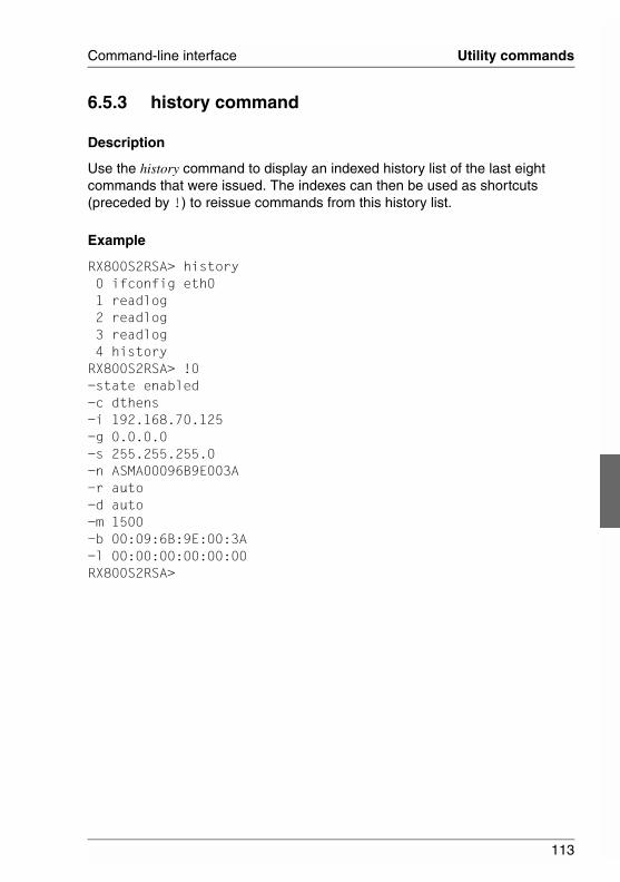
113
Command-line interface Utility commands
6.5.3 history command
Description
Use the history command to display an indexed history list of the last eight commands that were issued. The indexes can then be used as shortcuts (preceded by !) to reissue commands from this history list.
Example
RX800S2RSA> history 0 ifconfig eth0 1 readlog 2 readlog 3 readlog 4 historyRX800S2RSA> !0-state enabled-c dthens-i 192.168.70.125-g 0.0.0.0-s 255.255.255.0-n ASMA00096B9E003A-r auto-d auto-m 1500-b 00:09:6B:9E:00:3A-l 00:00:00:00:00:00RX800S2RSA>
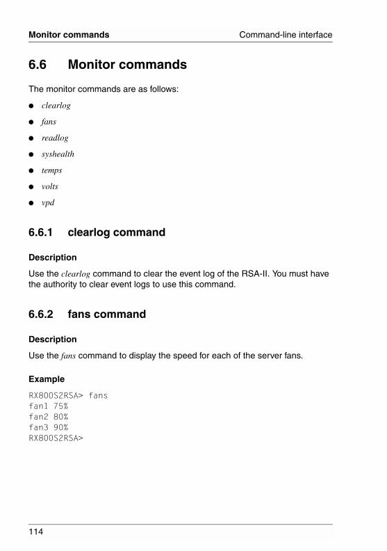
114
Monitor commands Command-line interface
© c
ogni
tas.
Ges
ells
chft
für
Tech
nik-
Dok
umen
tatio
n m
bH 2
006
Pfa
d: D
:\Akt
uelle
s_P
roje
kt\P
RIM
ER
GY
\RX
800S
3\rs
a-rx
800s
2-s3
_us\
RS
A_e
.k06
6.6 Monitor commands
The monitor commands are as follows:
● clearlog
● fans
● readlog
● syshealth
● temps
● volts
● vpd
6.6.1 clearlog command
Description
Use the clearlog command to clear the event log of the RSA-II. You must have the authority to clear event logs to use this command.
6.6.2 fans command
Description
Use the fans command to display the speed for each of the server fans.
Example
RX800S2RSA> fansfan1 75%fan2 80%fan3 90%RX800S2RSA>
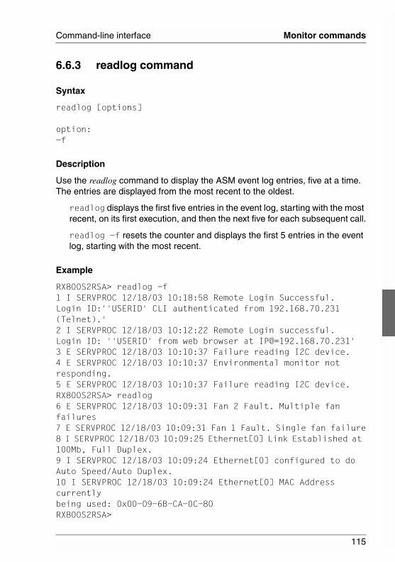
115
Command-line interface Monitor commands
6.6.3 readlog command
Syntax
readlog [options]
option:-f
Description
Use the readlog command to display the ASM event log entries, five at a time. The entries are displayed from the most recent to the oldest.
readlog displays the first five entries in the event log, starting with the most recent, on its first execution, and then the next five for each subsequent call.
readlog -f resets the counter and displays the first 5 entries in the event log, starting with the most recent.
Example
RX800S2RSA> readlog -f1 I SERVPROC 12/18/03 10:18:58 Remote Login Successful. Login ID:''USERID' CLI authenticated from 192.168.70.231 (Telnet).'2 I SERVPROC 12/18/03 10:12:22 Remote Login successful. Login ID: ''USERID' from web browser at IP@=192.168.70.231'3 E SERVPROC 12/18/03 10:10:37 Failure reading I2C device. 4 E SERVPROC 12/18/03 10:10:37 Environmental monitor not responding. 5 E SERVPROC 12/18/03 10:10:37 Failure reading I2C device. RX800S2RSA> readlog6 E SERVPROC 12/18/03 10:09:31 Fan 2 Fault. Multiple fan failures7 E SERVPROC 12/18/03 10:09:31 Fan 1 Fault. Single fan failure8 I SERVPROC 12/18/03 10:09:25 Ethernet[0] Link Established at 100Mb, Full Duplex.9 I SERVPROC 12/18/03 10:09:24 Ethernet[0] configured to do Auto Speed/Auto Duplex.10 I SERVPROC 12/18/03 10:09:24 Ethernet[0] MAC Address currently being used: 0x00-09-6B-CA-0C-80RX800S2RSA>

116
Monitor commands Command-line interface
© c
ogni
tas.
Ges
ells
chft
für
Tech
nik-
Dok
umen
tatio
n m
bH 2
006
Pfa
d: D
:\Akt
uelle
s_P
roje
kt\P
RIM
ER
GY
\RX
800S
3\rs
a-rx
800s
2-s3
_us\
RS
A_e
.k06
6.6.4 syshealth command
Description
Use the syshealth command to get a summary of the health of the server. The power state, system state, restart count, and RSA-II software status are displayed.
Example
RX800S2RSA> syshealthPower OnState System power off/State unknownDD not activeRestarts 0RX800S2RSA>
6.6.5 temps command
Description
Use the temps command to display all the temperatures and temperature thresholds. The same set of temperatures are displayed as in the Web interface.
Example
RX800S2RSA> temps
Temperatures are displayed in degrees Fahrenheit/Celsius
WR W T SS HS----------------------------------------CPU1 65/18 72/22 80/27 85/29 90/32CPU2 58/14 72/22 80/27 85/29 9/320DASD1 66/19 73/23 82/28 88/31 9/332Amb 59/15 70/21 83/28 90/32 9/355RX800S2RSA>
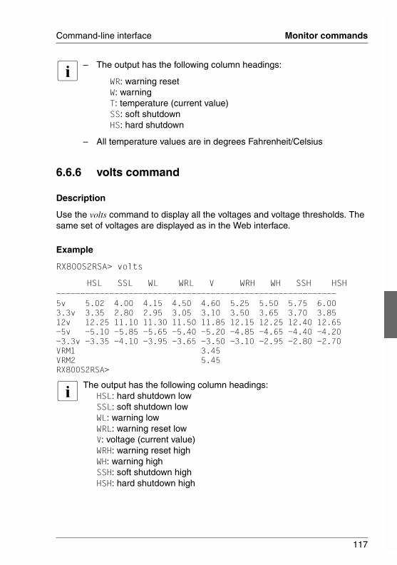
117
Command-line interface Monitor commands
I – The output has the following column headings:
WR: warning resetW: warningT: temperature (current value)SS: soft shutdownHS: hard shutdown
– All temperature values are in degrees Fahrenheit/Celsius
6.6.6 volts command
Description
Use the volts command to display all the voltages and voltage thresholds. The same set of voltages are displayed as in the Web interface.
Example
RX800S2RSA> volts
HSL SSL WL WRL V WRH WH SSH HSH----------------------------------------------------------5v 5.02 4.00 4.15 4.50 4.60 5.25 5.50 5.75 6.003.3v 3.35 2.80 2.95 3.05 3.10 3.50 3.65 3.70 3.8512v 12.25 11.10 11.30 11.50 11.85 12.15 12.25 12.40 12.65-5v -5.10 -5.85 -5.65 -5.40 -5.20 -4.85 -4.65 -4.40 -4.20-3.3v -3.35 -4.10 -3.95 -3.65 -3.50 -3.10 -2.95 -2.80 -2.70VRM1 3.45VRM2 5.45RX800S2RSA>
I The output has the following column headings:HSL: hard shutdown lowSSL: soft shutdown lowWL: warning lowWRL: warning reset lowV: voltage (current value)WRH: warning reset highWH: warning highSSH: soft shutdown highHSH: hard shutdown high
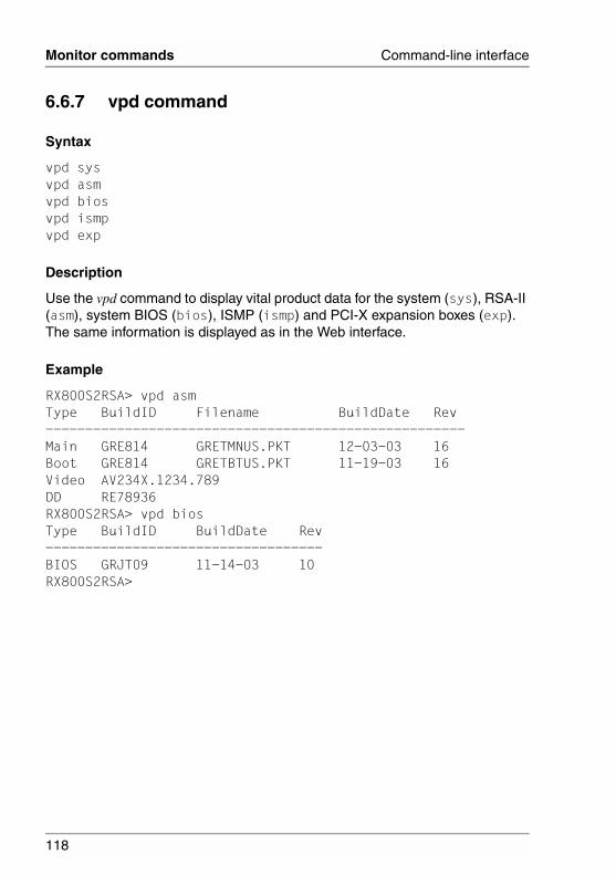
118
Monitor commands Command-line interface
© c
ogni
tas.
Ges
ells
chft
für
Tech
nik-
Dok
umen
tatio
n m
bH 2
006
Pfa
d: D
:\Akt
uelle
s_P
roje
kt\P
RIM
ER
GY
\RX
800S
3\rs
a-rx
800s
2-s3
_us\
RS
A_e
.k06
6.6.7 vpd command
Syntax
vpd sysvpd asmvpd biosvpd ismpvpd exp
Description
Use the vpd command to display vital product data for the system (sys), RSA-II (asm), system BIOS (bios), ISMP (ismp) and PCI-X expansion boxes (exp). The same information is displayed as in the Web interface.
Example
RX800S2RSA> vpd asmType BuildID Filename BuildDate Rev----------------------------------------------------- Main GRE814 GRETMNUS.PKT 12-03-03 16Boot GRE814 GRETBTUS.PKT 11-19-03 16Video AV234X.1234.789DD RE78936RX800S2RSA> vpd biosType BuildID BuildDate Rev-----------------------------------BIOS GRJT09 11-14-03 10RX800S2RSA>
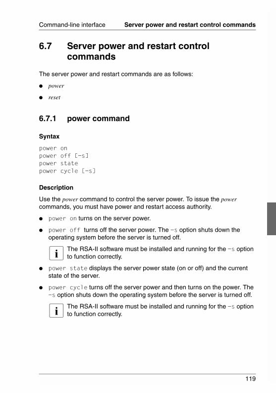
119
Command-line interface Server power and restart control commands
6.7 Server power and restart control commands
The server power and restart commands are as follows:
● power
● reset
6.7.1 power command
Syntax
power on power off [-s]power statepower cycle [-s]
Description
Use the power command to control the server power. To issue the power commands, you must have power and restart access authority.
● power on turns on the server power.
● power off turns off the server power. The -s option shuts down the operating system before the server is turned off.
I The RSA-II software must be installed and running for the -s option to function correctly.
● power state displays the server power state (on or off) and the current state of the server.
● power cycle turns off the server power and then turns on the power. The -s option shuts down the operating system before the server is turned off.
I The RSA-II software must be installed and running for the -s option to function correctly.
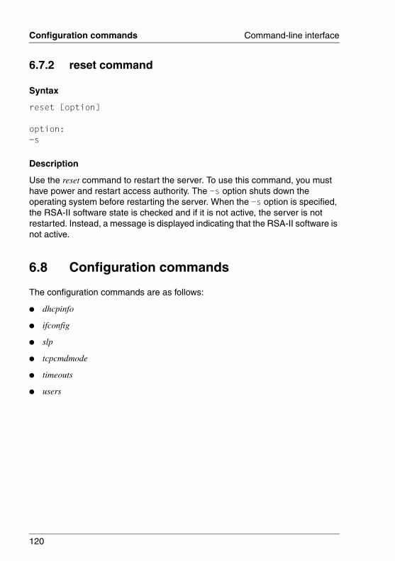
120
Configuration commands Command-line interface
© c
ogni
tas.
Ges
ells
chft
für
Tech
nik-
Dok
umen
tatio
n m
bH 2
006
Pfa
d: D
:\Akt
uelle
s_P
roje
kt\P
RIM
ER
GY
\RX
800S
3\rs
a-rx
800s
2-s3
_us\
RS
A_e
.k06
6.7.2 reset command
Syntax
reset [option]
option:-s
Description
Use the reset command to restart the server. To use this command, you must have power and restart access authority. The -s option shuts down the operating system before restarting the server. When the -s option is specified, the RSA-II software state is checked and if it is not active, the server is not restarted. Instead, a message is displayed indicating that the RSA-II software is not active.
6.8 Configuration commands
The configuration commands are as follows:
● dhcpinfo
● ifconfig
● slp
● tcpcmdmode
● timeouts
● users
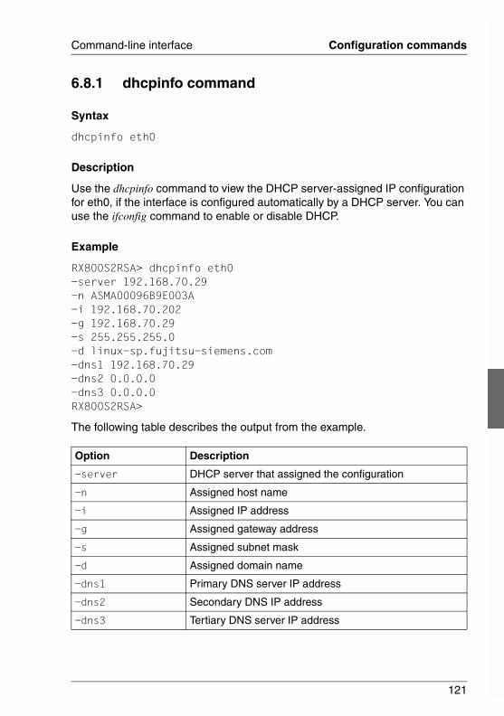
121
Command-line interface Configuration commands
6.8.1 dhcpinfo command
Syntax
dhcpinfo eth0
Description
Use the dhcpinfo command to view the DHCP server-assigned IP configuration for eth0, if the interface is configured automatically by a DHCP server. You can use the ifconfig command to enable or disable DHCP.
Example
RX800S2RSA> dhcpinfo eth0-server 192.168.70.29-n ASMA00096B9E003A-i 192.168.70.202-g 192.168.70.29-s 255.255.255.0-d linux-sp.fujitsu-siemens.com-dns1 192.168.70.29-dns2 0.0.0.0-dns3 0.0.0.0RX800S2RSA>
The following table describes the output from the example.
Option Description
-server DHCP server that assigned the configuration
-n Assigned host name
-i Assigned IP address
-g Assigned gateway address
-s Assigned subnet mask
-d Assigned domain name
-dns1 Primary DNS server IP address
-dns2 Secondary DNS IP address
-dns3 Tertiary DNS server IP address
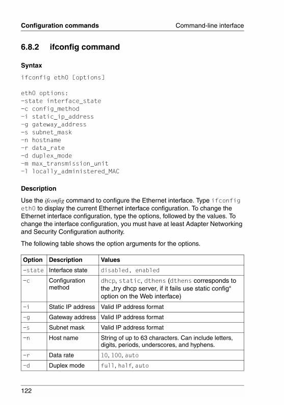
122
Configuration commands Command-line interface
© c
ogni
tas.
Ges
ells
chft
für
Tech
nik-
Dok
umen
tatio
n m
bH 2
006
Pfa
d: D
:\Akt
uelle
s_P
roje
kt\P
RIM
ER
GY
\RX
800S
3\rs
a-rx
800s
2-s3
_us\
RS
A_e
.k06
6.8.2 ifconfig command
Syntax
ifconfig eth0 [options]
eth0 options:-state interface_state-c config_method-i static_ip_address-g gateway_address-s subnet_mask-n hostname-r data_rate-d duplex_mode-m max_transmission_unit-l locally_administered_MAC
Description
Use the ifconfig command to configure the Ethernet interface. Type ifconfig eth0 to display the current Ethernet interface configuration. To change the Ethernet interface configuration, type the options, followed by the values. To change the interface configuration, you must have at least Adapter Networking and Security Configuration authority.
The following table shows the option arguments for the options.
Option Description Values
-state Interface state disabled, enabled
-c Configuration method
dhcp, static, dthens (dthens corresponds to the „try dhcp server, if it fails use static config“ option on the Web interface)
-i Static IP address Valid IP address format
-g Gateway address Valid IP address format
-s Subnet mask Valid IP address format
-n Host name String of up to 63 characters. Can include letters, digits, periods, underscores, and hyphens.
-r Data rate 10, 100, auto
-d Duplex mode full, half, auto
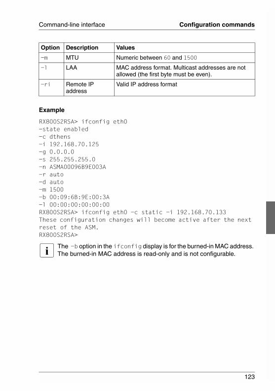
123
Command-line interface Configuration commands
Example
RX800S2RSA> ifconfig eth0-state enabled-c dthens-i 192.168.70.125-g 0.0.0.0-s 255.255.255.0-n ASMA00096B9E003A-r auto-d auto-m 1500-b 00:09:6B:9E:00:3A-l 00:00:00:00:00:00RX800S2RSA> ifconfig eth0 -c static -i 192.168.70.133These configuration changes will become active after the next reset of the ASM.RX800S2RSA>
I The -b option in the ifconfig display is for the burned-in MAC address. The burned-in MAC address is read-only and is not configurable.
-m MTU Numeric between 60 and 1500
-l LAA MAC address format. Multicast addresses are not allowed (the first byte must be even).
-ri Remote IP address
Valid IP address format
Option Description Values
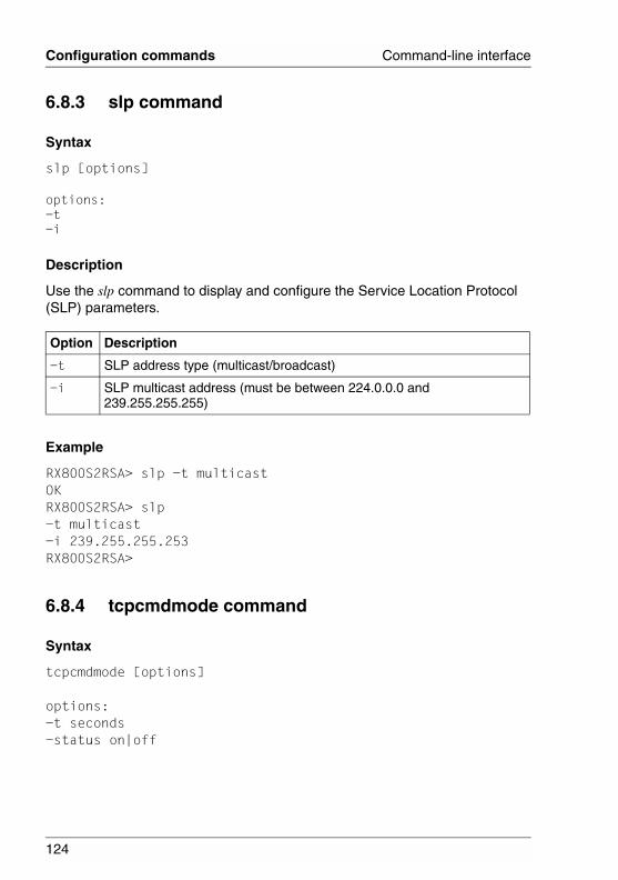
124
Configuration commands Command-line interface
© c
ogni
tas.
Ges
ells
chft
für
Tech
nik-
Dok
umen
tatio
n m
bH 2
006
Pfa
d: D
:\Akt
uelle
s_P
roje
kt\P
RIM
ER
GY
\RX
800S
3\rs
a-rx
800s
2-s3
_us\
RS
A_e
.k06
6.8.3 slp command
Syntax
slp [options]
options:-t-i
Description
Use the slp command to display and configure the Service Location Protocol (SLP) parameters.
Example
RX800S2RSA> slp -t multicastOKRX800S2RSA> slp-t multicast-i 239.255.255.253RX800S2RSA>
6.8.4 tcpcmdmode command
Syntax
tcpcmdmode [options]
options:-t seconds-status on|off
Option Description
-t SLP address type (multicast/broadcast)
-i SLP multicast address (must be between 224.0.0.0 and 239.255.255.255)
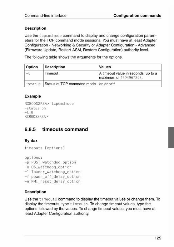
125
Command-line interface Configuration commands
Description
Use the tcpcmdmode command to display and change configuration param-eters for the TCP command mode sessions. You must have at least Adapter Configuration - Networking & Security or Adapter Configuration - Advanced (Firmware Update, Restart ASM, Restore Configuration) authority level.
The following table shows the arguments for the options.
Example
RX800S2RSA> tcpcmdmode-status on-t 0RX800S2RSA>
6.8.5 timeouts command
Syntax
timeouts [options]
options:-p POST_watchdog_option-o OS_watchdog_option-l loader_watchdog_option-f power_off_delay_option-n NMI_reset_delay_option
Description
Use the timeouts command to display the timeout values or change them. To display the timeouts, type timeouts. To change timeout values, type the options followed by the values. To change timeout values, you must have at least Adapter Configuration authority.
Option Description Values
-t Timeout A timeout value in seconds, up to a maximum of 4294967295.
-status Status of TCP command mode on or off
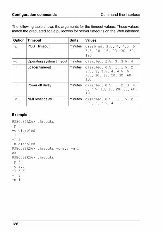
126
Configuration commands Command-line interface
© c
ogni
tas.
Ges
ells
chft
für
Tech
nik-
Dok
umen
tatio
n m
bH 2
006
Pfa
d: D
:\Akt
uelle
s_P
roje
kt\P
RIM
ER
GY
\RX
800S
3\rs
a-rx
800s
2-s3
_us\
RS
A_e
.k06
The following table shows the arguments for the timeout values. These values match the graduated scale pulldowns for server timeouts on the Web interface.
Example
RX800S2RSA> timeouts-p 5-o disabled-l 3.5-f 3-n disabledRX800S2RSA> timeouts -o 2.5 -n 1okRX800S2RSA> timeouts-p 5-o 2.5-l 3.5-f 3-n 1
Option Timeout Units Values
-p POST timeout minutes disabled, 3.5, 4, 4.5, 5, 7.5, 10, 15, 20, 30, 60, 120
-o Operating system timeout minutes disabled, 2.5, 3, 3.5, 4
-l Loader timeout minutes disabled, 0.5, 1, 1.5, 2, 2.5, 3, 3.5, 4, 4.5, 5, 7.5, 10, 15, 20, 30, 60, 120
-f Power off delay minutes disabled, 0.5, 1, 2, 3, 4, 5, 7.5, 10, 15, 20, 30, 60, 120
-n NMI reset delay minutes disabled, 0.5, 1, 1.5, 2, 2.5, 3, 3.5, 4
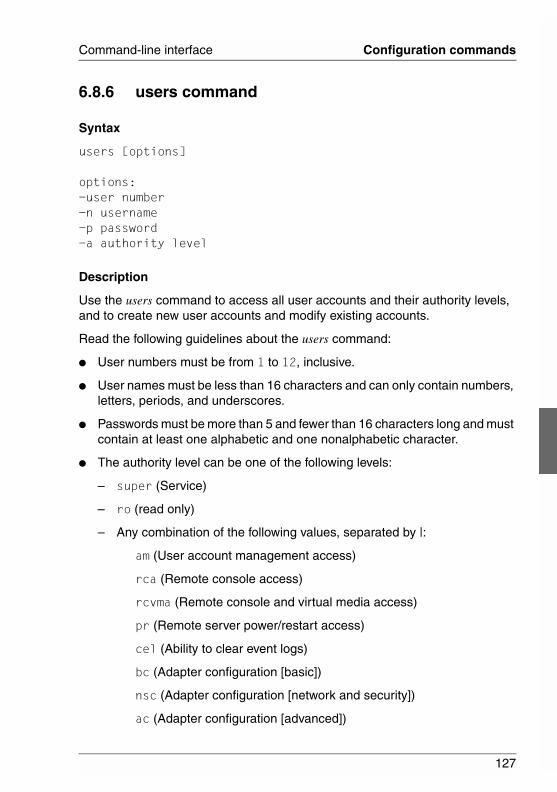
127
Command-line interface Configuration commands
6.8.6 users command
Syntax
users [options]
options:-user number-n username-p password-a authority level
Description
Use the users command to access all user accounts and their authority levels, and to create new user accounts and modify existing accounts.
Read the following guidelines about the users command:
● User numbers must be from 1 to 12, inclusive.
● User names must be less than 16 characters and can only contain numbers, letters, periods, and underscores.
● Passwords must be more than 5 and fewer than 16 characters long and must contain at least one alphabetic and one nonalphabetic character.
● The authority level can be one of the following levels:
– super (Service)
– ro (read only)
– Any combination of the following values, separated by |:
am (User account management access)
rca (Remote console access)
rcvma (Remote console and virtual media access)
pr (Remote server power/restart access)
cel (Ability to clear event logs)
bc (Adapter configuration [basic])
nsc (Adapter configuration [network and security])
ac (Adapter configuration [advanced])
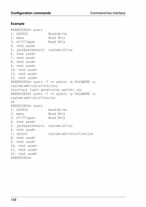
128
Configuration commands Command-line interface
© c
ogni
tas.
Ges
ells
chft
für
Tech
nik-
Dok
umen
tatio
n m
bH 2
006
Pfa
d: D
:\Akt
uelle
s_P
roje
kt\P
RIM
ER
GY
\RX
800S
3\rs
a-rx
800s
2-s3
_us\
RS
A_e
.k06
Example
RX800S2RSA> users1. USERID Read/Write2. manu Read Only3. eliflippen Read Only4. <not used>5. jacobyackenovic custom:cel|ac6. <not used>7. <not used>8. <not used>9. <not used>10. <not used>11. <not used>12. <not used>RX800S2RSA> users -7 -n sptest -p PASSW0RD -a custom:am|rca|cel|nsc|ascIncorrect login permission option: ascRX800S2RSA> users -7 -n sptest -p PASSW0RD -a custom:am|rca|cel|nsc|acokRX800S2RSA> users1. USERID Read/Write2. manu Read Only3. eliflippen Read Only4. <not used>5. jacobyackenovic custom:cel|ac6. <not used>7. sptest custom:am|rca|cel|nsc|ac8. <not used>9. <not used>10. <not used>11. <not used>12. <not used>RX800S2RSA>
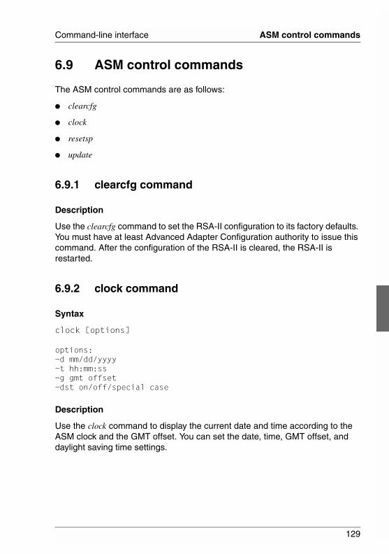
129
Command-line interface ASM control commands
6.9 ASM control commands
The ASM control commands are as follows:
● clearcfg
● clock
● resetsp
● update
6.9.1 clearcfg command
Description
Use the clearcfg command to set the RSA-II configuration to its factory defaults. You must have at least Advanced Adapter Configuration authority to issue this command. After the configuration of the RSA-II is cleared, the RSA-II is restarted.
6.9.2 clock command
Syntax
clock [options]
options:-d mm/dd/yyyy-t hh:mm:ss-g gmt offset-dst on/off/special case
Description
Use the clock command to display the current date and time according to the ASM clock and the GMT offset. You can set the date, time, GMT offset, and daylight saving time settings.
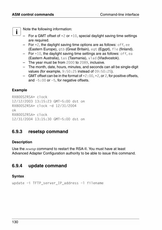
130
ASM control commands Command-line interface
© c
ogni
tas.
Ges
ells
chft
für
Tech
nik-
Dok
umen
tatio
n m
bH 2
006
Pfa
d: D
:\Akt
uelle
s_P
roje
kt\P
RIM
ER
GY
\RX
800S
3\rs
a-rx
800s
2-s3
_us\
RS
A_e
.k06
I Note the following information:
– For a GMT offset of +2 or +10, special daylight saving time settings are required.
– For +2, the daylight saving time options are as follows: off, ee (Eastern Europe), gtb (Great Britain), egt (Egypt), fle (finland).
– For +10, the daylight saving time settings are as follows: off, ea (Eastern Australia), tas (Tasmania), vlad (Vladivostok).
– The year must be from 2000 to 2089, inclusive. – The month, date, hours, minutes, and seconds can all be single-digit
values (for example, 9:50:25 instead of 09:50:25). – GMT offset can be in the format of +2:00, +2, or 2, for positive offsets,
and -5:00 or -5, for negative offsets.
Example
RX800S2RSA> clock12/12/2003 13:15:23 GMT-5:00 dst onRX800S2RSA> clock -d 12/31/2004okRX800S2RSA> clock12/31/2004 13:15:30 GMT-5:00 dst on
6.9.3 resetsp command
Description
Use the resetsp command to restart the RSA-II. You must have at least Advanced Adapter Configuration authority to be able to issue this command.
6.9.4 update command
Syntax
update -i TFTP_server_IP_address -l filename
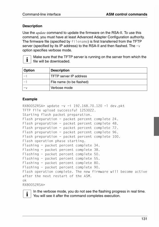
131
Command-line interface ASM control commands
Description
Use the update command to update the firmware on the RSA-II. To use this command, you must have at least Advanced Adapter Configuration authority. The firmware file (specified by filename) is first transferred from the TFTP server (specified by its IP address) to the RSA-II and then flashed. The -v option specifies verbose mode.
I Make sure that the TFTP server is running on the server from which the file will be downloaded.
Example
RX800S2RSA> update -v -i 192.168.70.120 -l dev.pktTFTP file upload successful 1253022.Starting flash packet preparation.Flash preparation - packet percent complete 24.Flash preparation - packet percent complete 48.Flash preparation - packet percent complete 72.Flash preparation - packet percent complete 96.Flash preparation - packet percent complete 100.Flash operation phase starting.Flashing - packet percent complete 34.Flashing - packet percent complete 38.Flashing - packet percent complete 50.Flashing - packet percent complete 55.Flashing - packet percent complete 80.Flashing - packet percent complete 90.Flash operation complete. The new firmware will become activeafter the next restart of the ASM.okRX800S2RSA>
I In the verbose mode, you do not see the flashing progress in real time. You will see it after the command completes execution.
Option Description
-i TFTP server IP address
-l File name (to be flashed)
-v Verbose mode

133
Related PublicationsManuals for PRIMERGY server systems are available as PDF files on the ServerBooks CD. The ServerBooks CD is part of the PRIMERGY ServerView Suite delivered with each server system.
The current versions of the required manuals can be downloaded free of charge as PDF files from the Internet. The overview page showing the online documen-tation available on the Internet can be found via the URL:http://manuals.fujitsu-siemens.com (choose: industry standard servers).
[1] SafetyTechnical Manual
[2] ErgonomicsTechnical Manual
[3] WarrantyTechnical Manual
[4] PRIMERGY RX800 S2Operating Manual
[5] PRIMERGY RX800 S2Options Guide
[6] PRIMERGY RX800 S3Operating Manual
[7] PRIMERGY RX800 S3Options Guide
[8] PRIMERGY RX800 S2/S3ServeRAID-8i HDD ControllerUser Manual
[9] Quickstart Hardware - PRIMERGY RX800 S3Poster
[10] Quickstart Software - PRIMERGY ServerView SuitePoster
134
Related publications
© c
ogni
tas.
Ges
ells
chft
für
Tech
nik-
Dok
umen
tatio
n m
bH 2
006
Pfa
d: D
:\Akt
uelle
s_P
roje
kt\P
RIM
ER
GY
\RX
800S
3\rs
a-rx
800s
2-s3
_us\
RS
A_e
.lit
[11] PRIMERGY ServerView Suite ServerStartUser Manual
[12] PRIMERGY ServerView Suite RemoteViewUser Manual
[13] PRIMERGY ServerView Suite ServerView S2Server ManagementUser Manual
[14] PRIMERGY ServerView Suite ServerViewServer ManagementUser Manual
135
IndexAAccessing the command line 109ASM
control commands 129defaults restoration 77
CCLI
access 109features 110limitations 110syntax 110
command line interfaceaccess 109features and limitations 110
command syntax 110commands
ASM control 129configuring 120monitoring 114power and restart control 119utilities 112
concept of manual 9configuration commands 120configuration file usage 74configuring
Ethernet connection 49global login settings 34network protocols 54port assignments 47remote alert settings 36Secure Shell server 71security 58
creating a login profile 30
Ddocumentation overview 9, 10documents related to this manual 10
EEthernet connection configuration 49event log viewing 85
Ffirmware update for RSA-II 107
Gglobal login settings configuration 34
Llogging in to the command-line
session 109logging in to the RSA-II 13logging off 78login profile creation 30
Mmonitor commands 114monitoring remote server status 79
Nnetwork protocols configuration 54notational conventions 12
Oopening and using the Web interface
13operating manual 10OS requirements 11overview of the documentation 9
Pport assigments configuration 47power and restart control commands
119power status remote control 96PXE network boot setup 106
136
Index
© c
ogni
tas.
Ges
ells
chft
für
Tech
nik-
Dok
umen
tatio
n m
bH 2
006
Pfa
d: D
:\Akt
uelle
s_P
roje
kt\P
RIM
ER
GY
\RX
800S
3\rs
a-rx
800s
2-s3
_us\
RS
A_e
.six
Rrelated publications 133remote alert settings configuration 36remote console
access 99keyboard support 100
remote disk 101remote power status control 96restoring ASM defaults 77RSA-II
action descriptions 16features 10firmware update 98
SSecure Shell server configuration 71security configuration 58server power and restart activity 94setting system information 23setting up PXE network boot 106system health viewing 79
Ttarget group of manual 9
Uupdating the RSA-II firmware 107using the configuration file 74utility commands 112
Vviewing system health 79viewing the event log 85viewing vital product data 88vital product data viewing 88
WWeb browser requirements 11

Comments on PRIMERGY RX800 S2/S3RemoteView Management Board RSA-II
CommentsSuggestionsCorrections
✁
Submitted by
Fujitsu Siemens Computers GmbHUser Documentation33094 PaderbornGermany
Fax: (++49) 700 / 372 00001
email: [email protected]://manuals.fujitsu-siemens.com

© c
ogni
tas.
Ges
ells
chft
für
Tech
nik-
Dok
umen
tatio
n m
bH 2
006
Pfa
d: D
:\Akt
uelle
s_P
roje
kt\P
RIM
ER
GY
\RX
800S
3\rs
a-rx
800s
2-s3
_us\
RS
A_e
.nac
Information on this document On April 1, 2009, Fujitsu became the sole owner of Fujitsu Siemens Compu-ters. This new subsidiary of Fujitsu has been renamed Fujitsu Technology So-lutions.
This document from the document archive refers to a product version which was released a considerable time ago or which is no longer marketed.
Please note that all company references and copyrights in this document have been legally transferred to Fujitsu Technology Solutions.
Contact and support addresses will now be offered by Fujitsu Technology So-lutions and have the format …@ts.fujitsu.com.
The Internet pages of Fujitsu Technology Solutions are available at http://ts.fujitsu.com/... and the user documentation at http://manuals.ts.fujitsu.com.
Copyright Fujitsu Technology Solutions, 2009
Hinweise zum vorliegenden Dokument Zum 1. April 2009 ist Fujitsu Siemens Computers in den alleinigen Besitz von Fujitsu übergegangen. Diese neue Tochtergesellschaft von Fujitsu trägt seit-dem den Namen Fujitsu Technology Solutions.
Das vorliegende Dokument aus dem Dokumentenarchiv bezieht sich auf eine bereits vor längerer Zeit freigegebene oder nicht mehr im Vertrieb befindliche Produktversion.
Bitte beachten Sie, dass alle Firmenbezüge und Copyrights im vorliegenden Dokument rechtlich auf Fujitsu Technology Solutions übergegangen sind.
Kontakt- und Supportadressen werden nun von Fujitsu Technology Solutions angeboten und haben die Form …@ts.fujitsu.com.
Die Internetseiten von Fujitsu Technology Solutions finden Sie unter http://de.ts.fujitsu.com/..., und unter http://manuals.ts.fujitsu.com finden Sie die Benutzerdokumentation.
Copyright Fujitsu Technology Solutions, 2009