Embed Size (px)
DESCRIPTION
o Installation of RFS CELLFLEX ® cables Version 2003-8 Technical Consulting European Sales & Customer Service Radio Frequency Systems GmbH Kabelkamp 20, 30179 Hannover (Germany) Phone: +49 (0)511 676 2418 Fax: +49 (0)511 676 2471 E-mail: [email protected] Side 1 of 41 This Presentation is written in the year of 2003 Before using please have a check of topically! RFS/HSR/Ahlenstorf/Version 2003-8
Citation preview

Side 1 of 41 RFS/HSR/Ahlenstorf/Version 2003-8
RFS Installation training
o Installation of RFS CELLFLEX® cables
o Installation Instructions and Data sheets for CELLFLEX® cables and accessories This Presentation is written in the year of 2003 Before using please have a check of topically! Version 2003-8
Responsible Fredy Ahlenstorf Technical Consulting European Sales & Customer Service Radio Frequency Systems GmbH Kabelkamp 20, 30179 Hannover (Germany) Phone: +49 (0)511 676 2418 Fax: +49 (0)511 676 2471 E-mail: [email protected]
Hold by Authorised Training Manager: Fredy Ahlenstorf
Technical Consulting European Sales & Customer Service Radio Frequency Systems GmbH Kabelkamp 20, 30179 Hannover (Germany) Phone: +49 (0)511 676 2418 Fax: +49 (0)511 676 2471 E-mail: [email protected]

Side 2 of 41 RFS/HSR/Ahlenstorf/Version 2003-8
®
________________________________
________________________________
________________________________
________________________________
________________________________
________________________________
________________________________
RFS/HSR/Ahlenstorf/Version 2003-82
Welcome - Introduction
Fredy AhlenstorfTechnical ConsultingEuropean Sales & Customer ServiceRadio Frequency Systems GmbHKabelkamp 20, 30179 Hannover (Germany)Phone: +49 (0)511 676 2418Fax: +49 (0)511 676 2471E-mail: [email protected]
Do you need support?Your Sales Partner are pleased to help you.The Technical Consulting Group of RFS will
support him/you
________________________________
________________________________
________________________________
________________________________
________________________________
________________________________
________________________________
RFS/HSR/Ahlenstorf/Version 2003-83
Information of RFS products
www.rfsworld.com
Visit us by internet
________________________________
________________________________
________________________________
________________________________
________________________________
________________________________
________________________________
Side 3 of 41 RFS/HSR/Ahlenstorf/Version 2003-8
RFS/HSR/Ahlenstorf/Version 2003-84
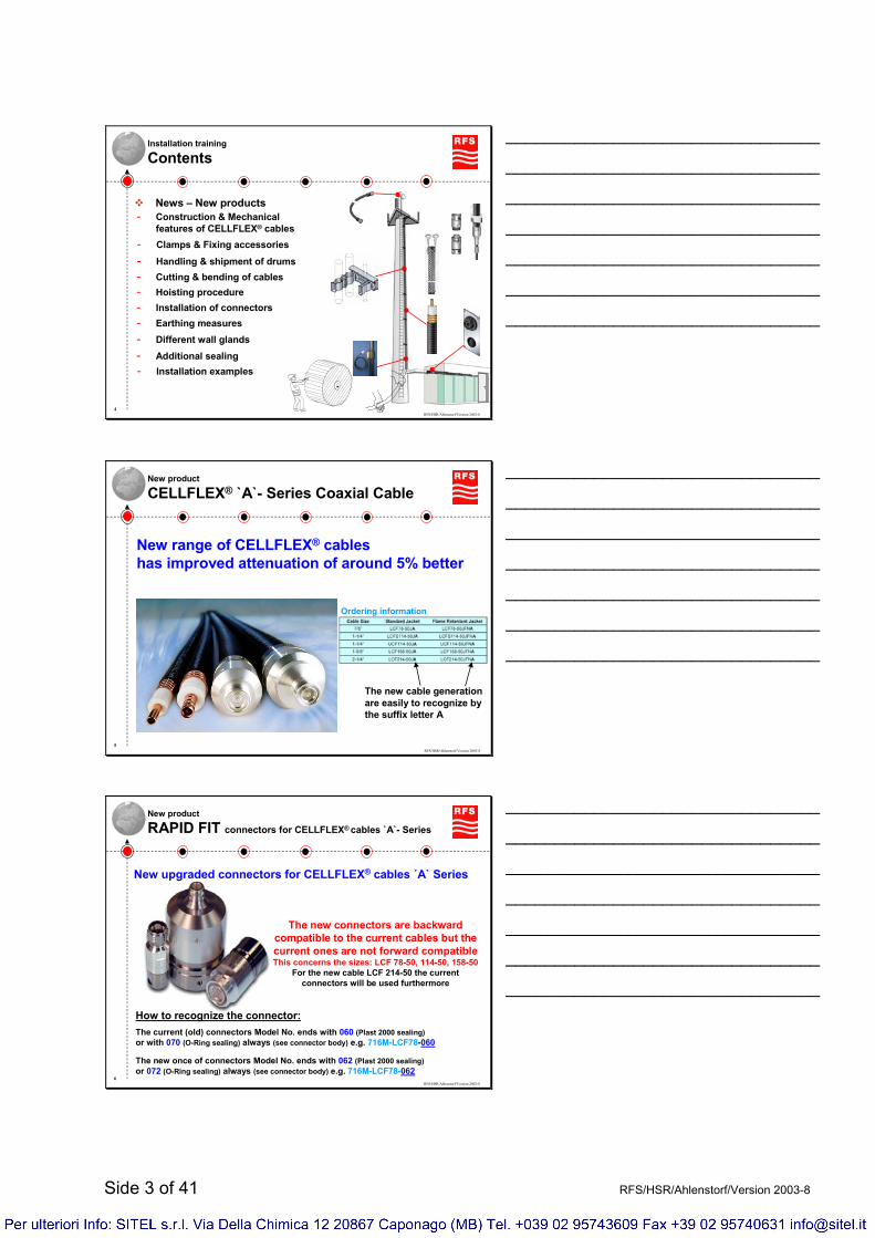
Installation training
Contents
- Clamps & Fixing accessories
- Construction & Mechanicalfeatures of CELLFLEX® cables
- Handling & shipment of drums- Cutting & bending of cables- Hoisting procedure- Installation of connectors
- Different wall glands- Additional sealing- Installation examples
- Earthing measures
News – New products
________________________________
________________________________
________________________________
________________________________
________________________________
________________________________
________________________________
RFS/HSR/Ahlenstorf/Version 2003-85
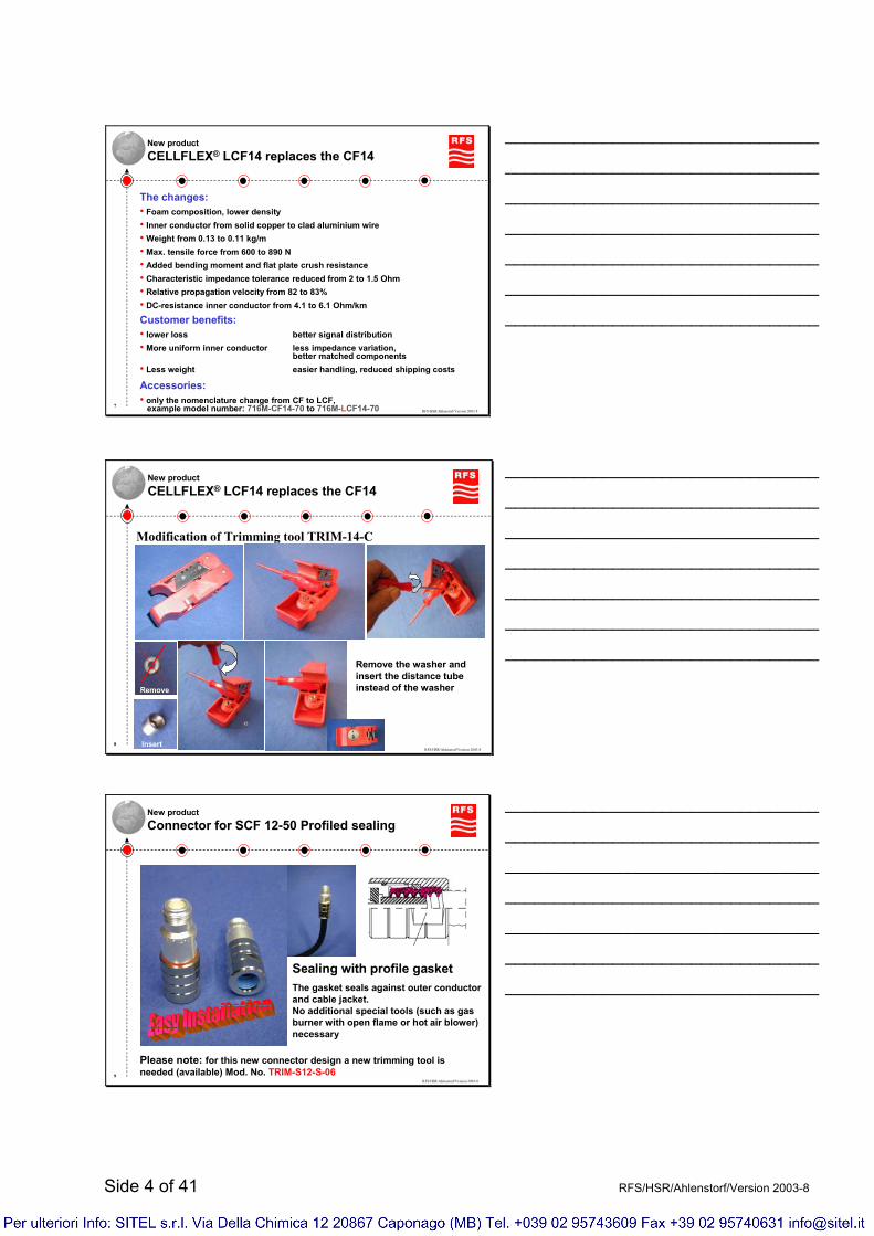
New product
CELLFLEX® `A`- Series Coaxial Cable
New range of CELLFLEX® cableshas improved attenuation of around 5% better
The new cable generation are easily to recognize by the suffix letter A
Ordering information
________________________________
________________________________
________________________________
________________________________
________________________________
________________________________
________________________________
RFS/HSR/Ahlenstorf/Version 2003-86
New product
RAPID FIT connectors for CELLFLEX® cables `A`- Series
New upgraded connectors for CELLFLEX® cables ´A` Series
The new connectors are backward compatible to the current cables but the current ones are not forward compatibleThis concerns the sizes: LCF 78-50, 114-50, 158-50
For the new cable LCF 214-50 the current connectors will be used furthermore
How to recognize the connector:The current (old) connectors Model No. ends with 060 (Plast 2000 sealing)or with 070 (O-Ring sealing) always (see connector body) e.g. 716M-LCF78-060
The new once of connectors Model No. ends with 062 (Plast 2000 sealing)or 072 (O-Ring sealing) always (see connector body) e.g. 716M-LCF78-062
________________________________
________________________________
________________________________
________________________________
________________________________
________________________________
________________________________
Side 4 of 41 RFS/HSR/Ahlenstorf/Version 2003-8
RFS/HSR/Ahlenstorf/Version 2003-87
New productCELLFLEX® LCF14 replaces the CF14
The changes:• Foam composition, lower density• Inner conductor from solid copper to clad aluminium wire• Weight from 0.13 to 0.11 kg/m• Max. tensile force from 600 to 890 N• Added bending moment and flat plate crush resistance• Characteristic impedance tolerance reduced from 2 to 1.5 Ohm• Relative propagation velocity from 82 to 83%• DC-resistance inner conductor from 4.1 to 6.1 Ohm/km
Customer benefits:• lower loss better signal distribution• More uniform inner conductor less impedance variation,
better matched components• Less weight easier handling, reduced shipping costs
Accessories:• only the nomenclature change from CF to LCF,
example model number: 716M-CF14-70 to 716M-LCF14-70
________________________________
________________________________
________________________________
________________________________
________________________________
________________________________
________________________________
RFS/HSR/Ahlenstorf/Version 2003-88
New productCELLFLEX® LCF14 replaces the CF14
Modification of Trimming tool TRIM-14-C
Remove the washer and insert the distance tube instead of the washerRemove
Insert
________________________________
________________________________
________________________________
________________________________
________________________________
________________________________
________________________________
RFS/HSR/Ahlenstorf/Version 2003-89
New productConnector for SCF 12-50 Profiled sealing
Sealing with profile gasketThe gasket seals against outer conductorand cable jacket.No additional special tools (such as gas burner with open flame or hot air blower) necessary
Please note: for this new connector design a new trimming tool is needed (available) Mod. No. TRIM-S12-S-06
________________________________
________________________________
________________________________
________________________________
________________________________
________________________________
________________________________

Side 5 of 41 RFS/HSR/Ahlenstorf/Version 2003-8
RFS/HSR/Ahlenstorf/Version 2003-810
Construction of RFS CELLFLEX® cables
• Inner conductor
- copper wire - solid aluminium copper clad- copper strand
• Dielectric - foam polyethylene
• Outer conductor
- copper tube- corrugated copper tube
• Jacket- abrasion resistant, halogen free,
UV resistant and non-corrosiveblack polyethylene
- LCF type:annularly corrugated copper tube
- SCF types:helically corrugated copper tube
________________________________
________________________________
________________________________
________________________________
________________________________
________________________________
________________________________
RFS/HSR/Ahlenstorf/Version 2003-811
Mechanical features of CELLFLEX® cables
Before starting installationnote the datasheets
- Minimum bending radius,single bending
- Minimum bending radius,repeated bending
- Maximum tensile force
- Recommended &max. clamp spacing
Please Note: The maximum hoisting length per hoisting stocking is 70m!
________________________________
________________________________
________________________________
________________________________
________________________________
________________________________
________________________________

Side 6 of 41 RFS/HSR/Ahlenstorf/Version 2003-8
RFS/HSR/Ahlenstorf/Version 2003-812
Mechanical properties CELLFLEX® cables
Super flexible cables
Ultra flexible cable
Low Loss cables
Cable size SCF 14-50 SCF 38-50 SCF 12-50 UCF 12-50 LCF 14-50 LCF 38-50 LCF 12-50 LCF 58-50 LCF 78-50
LCF 114-50( U C F 114 -
50 ) LCFS 114-50LCF 158-50 LCF 214-50
Weight, approx. 0 ,0 7 kg / m(0 ,0 5 lb/ ft )
0 ,12 kg / m(0 ,0 8 lb/ f t)
0 ,2 1 kg / m(0 ,14 lb/ f t)
0 ,2 4 kg / m(0 ,16 lb/ ft )
0 ,11 kg / m(0 ,0 7 4 lb/ f t)
0 ,12 kg / m(0 ,0 8 lb/ f t)
0 ,2 2 kg / m(0 ,15 lb/ f t)
0 ,3 7 kg / m(0 ,2 5 lb/ ft )
0 ,5 3 kg / m(0 ,3 6 lb/ ft )
1,0 5 kg / m(0 ,7 1 lb/ ft )
1,15 kg / m(0 ,7 7 lb/ f t)
1,5 3 kg / m(1,0 3 lb/ f t)
1,9 2 kg / m(1,2 9 lb/ f t)
Min. bending radiussingle bending
4 0 m m(1,6 in)
5 0 m m(2 in)
7 0 m m(3 in)
9 0 m m(4 in)
12 0 m m(5 in)
2 0 0 m m(8 in)
2 0 0 m m(8 in)
3 0 0 m m(12 in)
2 4 1 m m(9 ,5 in)
Min. bending radiusrepeated bending
2 5 m m(1 in)
2 5 m m(1 in)
3 2 m m(1,3 in)
3 0 m m(1,2 in)
12 0 m m(5 in)
9 5 m m(4 in)
12 5 m m(5 in)
19 0 m m(7 in)
2 5 0 m m(10 in)
3 8 0 m m(15 in)
3 8 0 m m(15 in)
5 0 0 m m(2 0 in)
5 6 0 m m(2 2 in)
Max. tensile force 6 0 0 N(13 5 lb)
6 0 0 N(13 5 lb)
6 5 0 N(14 6 lb)
7 0 0 N(15 7 lb)
8 9 0 N(2 0 0 lb)
5 3 0 N(119 lb)
110 0 N(2 4 7 lb)
115 0 N(2 5 9 lb)
14 4 0 N(3 2 4 lb)
10 2 0 N(2 2 9 lb)
2 5 7 0 N(5 7 8 lb)
17 4 0 N(3 9 1 lb)
2 6 10 N(5 8 7 lb)
Recommended/max.clamp spacing
0 ,2 m(8 in)
0 ,2 5 m(10 in)
0 ,3 m(1 ft )
0 ,3 m(1 f t)
0 ,5 / 1 m(1ft 8 in /3 ft 3 in)
0 ,5 / 1 m(1ft 8 in /3 f t 3 in)
0 ,6 / 1 m(2 ft /
3 ft 3 in)
0 ,7 / 1 m(2 ft 3 ,5 in /
3 ft 3 in)
0 ,8 / 1 m(2 ft 7 ,5 in /
3 ft 3 in)
1 / 1,2 m(3 ft 3 in /
4 f t)
1 / 1,2 m(3 ft 3 in /
4 f t)
1,2 / 1,5 m(4 /5 f t)
1,5 / 2 ,0 m(5 ft /
6 f t 7 in)
Maxim. Pulling lenghtper hoisting grip
Recommended temperature range
during installation J
during installation�JF, JFN
during operation�J, JF, JFN
during storage�J, JF, JFN
70m for all cable sizes
-40°C..+60°C (-40°F..+140°F) for all cable sizes
-25°C..+60°C (-13°F..+140°F) for all cable sizes
-40°C..+85°C (-40°F..+185°F) for all cable sizes
-70°C..+85°C (-94°F..+185°F) for all cable sizes
_________________________________________________________________________
_________________________________________________________________________
_________________________________________________________________________
RFS/HSR/Ahlenstorf/Version 2003-813
Fixing accessories
HCH clamps (for HELLIFLEX® cables)
- Different types for each installation interfaces
- Damage of cable very likely
Not recommend to use for LCF cables
Roundconstructions
Flatconstructions
Different sizesof anchor bar
Angle irons in different lengths
X
________________________________
________________________________
________________________________
________________________________
________________________________
________________________________
________________________________

Side 7 of 41 RFS/HSR/Ahlenstorf/Version 2003-8
RFS/HSR/Ahlenstorf/Version 2003-814
Fixing accessories
Snap-in & Bolt-on hanger
________________________________
________________________________
________________________________
________________________________
________________________________
________________________________
________________________________
RFS/HSR/Ahlenstorf/Version 2003-815
Fixing accessories
SCS clamp
- Different types for each installation interfaces
- Has to be handled carefullyto much torque at the screw damages the cable
+ Space saving+ Foolproof
Different interfaces availableAll types available for fixing one
up to three cables
________________________________
________________________________
________________________________
________________________________
________________________________
________________________________
________________________________
RFS/HSR/Ahlenstorf/Version 2003-816
Fixing accessories
SCS clamp - types
Its recommend to hook in the top upper part of the
anchor bar.
Note the max. torque of 2 NmTherefore the use of a socket wrench is recommended
________________________________
________________________________
________________________________
________________________________
________________________________
________________________________
________________________________

Side 8 of 41 RFS/HSR/Ahlenstorf/Version 2003-8
RFS/HSR/Ahlenstorf/Version 2003-817
Fixing accessories
Multi Block Hanger
Can be stacked up to three layersTo accept a total of 6 feeders
1 double saddles
2 threaded bar M8
3 pressure plate
4 3 hexagonal nuts
5 2 washers
________________________________
________________________________
________________________________
________________________________
________________________________
________________________________
________________________________
RFS/HSR/Ahlenstorf/Version 2003-818
Fixing accessories
Multi Block Hanger - Components
Angle or flat member
Round member
Direct Wall installation
C – rail(anchor bar) Through hole On Tube
________________________________
________________________________
________________________________
________________________________
________________________________
________________________________
________________________________
RFS/HSR/Ahlenstorf/Version 2003-819
Fixing accessories
RSB Clip
“Foolproof”can not deform cable
________________________________
________________________________
________________________________
________________________________
________________________________
________________________________
________________________________
Side 9 of 41 RFS/HSR/Ahlenstorf/Version 2003-8
RFS/HSR/Ahlenstorf/Version 2003-820
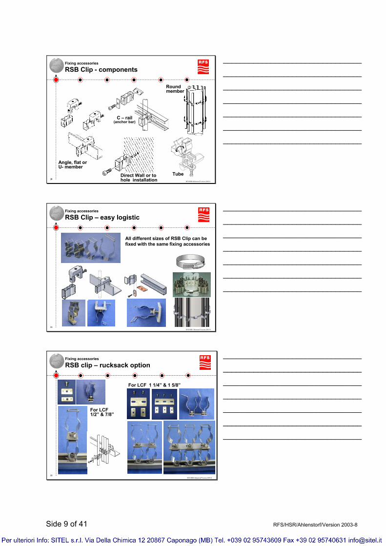
Fixing accessories
RSB Clip - components
Angle, flat orU- member
C – rail(anchor bar)
Direct Wall or to hole installation
Tube
Round member
________________________________
________________________________
________________________________
________________________________
________________________________
________________________________
________________________________
RFS/HSR/Ahlenstorf/Version 2003-821
Fixing accessories
RSB Clip – easy logistic
All different sizes of RSB Clip can be fixed with the same fixing accessories
________________________________
________________________________
________________________________
________________________________
________________________________
________________________________
________________________________
RFS/HSR/Ahlenstorf/Version 2003-822
Fixing accessories
RSB clip – rucksack option
For LCF 1 1/4” & 1 5/8”
For LCF 1/2” & 7/8”
________________________________
________________________________
________________________________
________________________________
________________________________
________________________________
________________________________
Side 10 of 41 RFS/HSR/Ahlenstorf/Version 2003-8
RFS/HSR/Ahlenstorf/Version 2003-823
Fixing accessories
RSB clip – with clamp lining for High flexible cables
Protect high flexible cables when moving due to wind
________________________________
________________________________
________________________________
________________________________
________________________________
________________________________
________________________________
RFS/HSR/Ahlenstorf/Version 2003-824
Fixing accessories
Fix cables in critical areas
Attachment with round member adapter kit
Fix the cable especially in critical areas !
RSB Clip or other kind of clamp fixed with long screw (8mm) on cleat, round member or anchor bar
Simple solution to stop the moving of the cable do to wind,but note:They can not carry the cable!
________________________________
________________________________
________________________________
________________________________
________________________________
________________________________
________________________________
RFS/HSR/Ahlenstorf/Version 2003-825
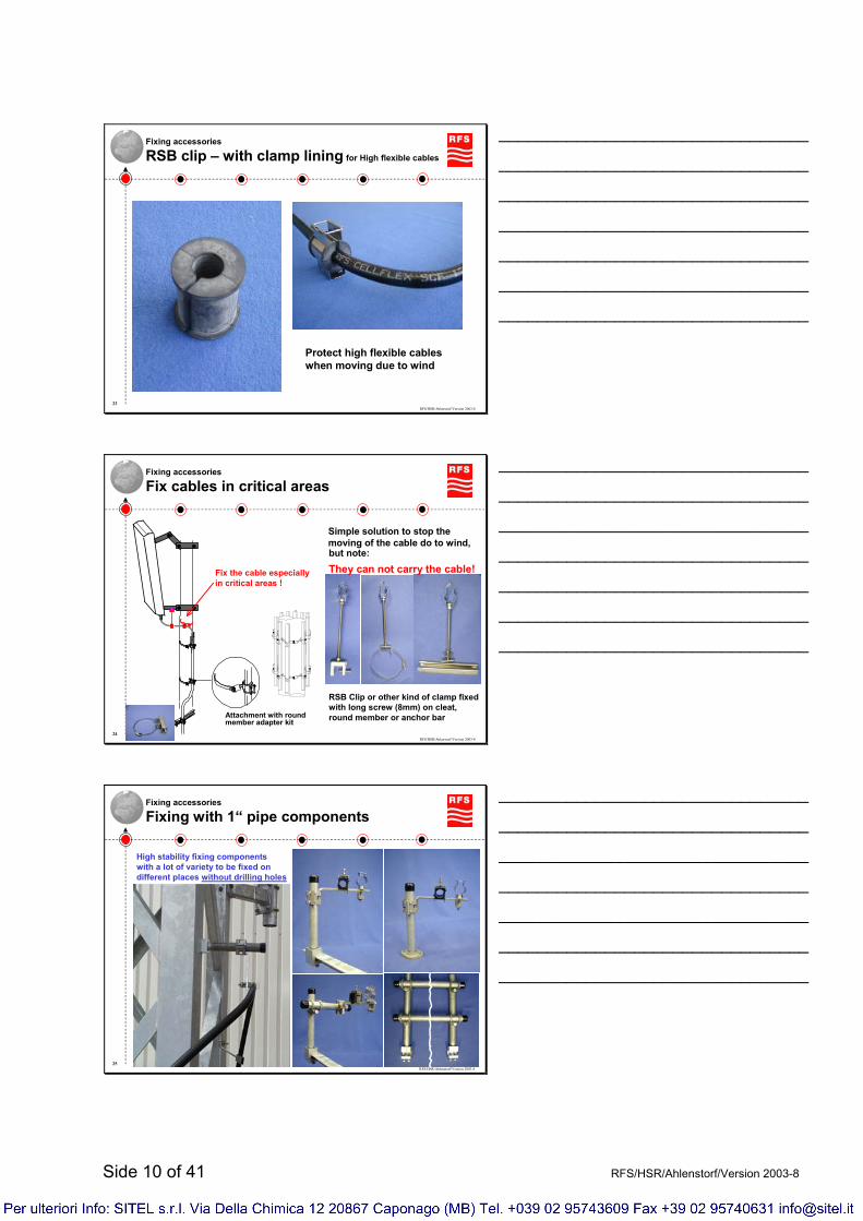
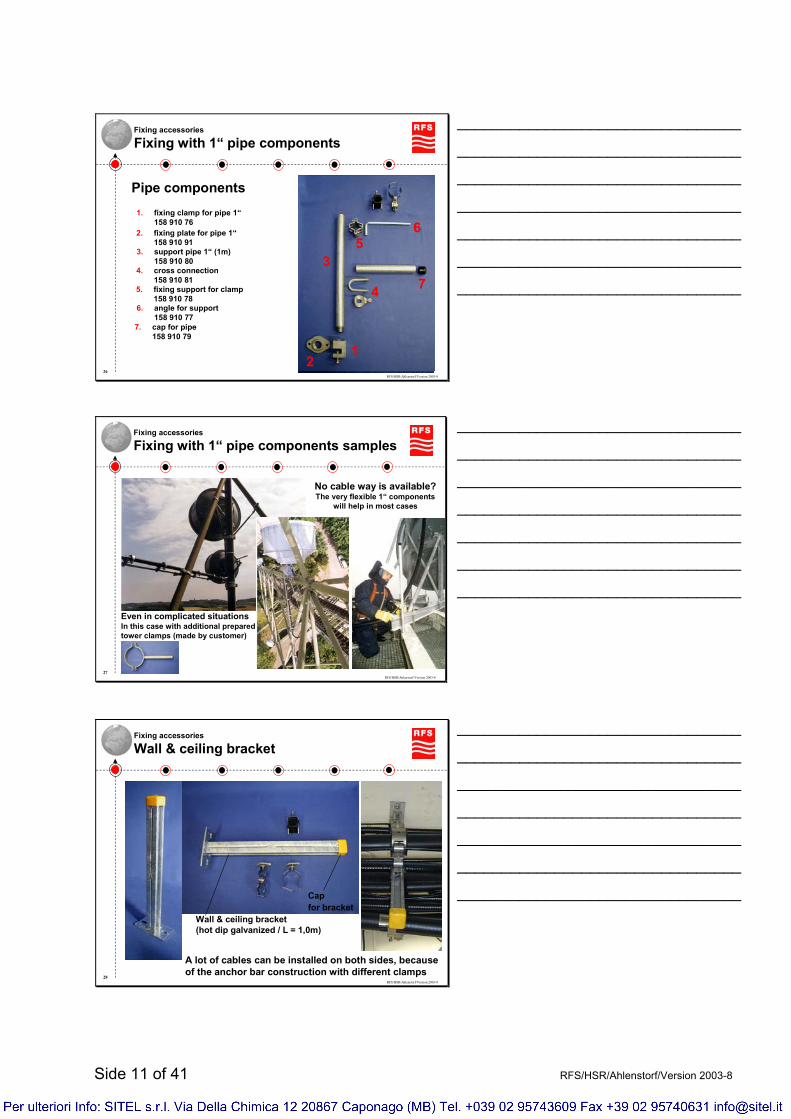
Fixing accessories
Fixing with 1“ pipe components
High stability fixing componentswith a lot of variety to be fixed on different places without drilling holes
________________________________
________________________________
________________________________
________________________________
________________________________
________________________________
________________________________
Side 11 of 41 RFS/HSR/Ahlenstorf/Version 2003-8
RFS/HSR/Ahlenstorf/Version 2003-826
Fixing accessories
Fixing with 1“ pipe components
1. fixing clamp for pipe 1“158 910 76
2. fixing plate for pipe 1“158 910 91
3. support pipe 1“ (1m)158 910 80
4. cross connection158 910 81
5. fixing support for clamp158 910 78
6. angle for support158 910 77
7. cap for pipe158 910 79
3
65
4 7
21
Pipe components
________________________________
________________________________
________________________________
________________________________
________________________________
________________________________
________________________________
RFS/HSR/Ahlenstorf/Version 2003-827
Fixing accessories
Fixing with 1“ pipe components samples
No cable way is available?The very flexible 1“ components
will help in most cases
Even in complicated situationsIn this case with additional prepared tower clamps (made by customer)
________________________________
________________________________
________________________________
________________________________
________________________________
________________________________
________________________________
RFS/HSR/Ahlenstorf/Version 2003-828
Fixing accessories
Wall & ceiling bracket
Wall & ceiling bracket (hot dip galvanized / L = 1,0m)
Capfor bracket
A lot of cables can be installed on both sides, because of the anchor bar construction with different clamps
________________________________
________________________________
________________________________
________________________________
________________________________
________________________________
________________________________

Side 12 of 41 RFS/HSR/Ahlenstorf/Version 2003-8
RFS/HSR/Ahlenstorf/Version 2003-829
Fixing accessories – special solutions
Wall & ceiling bracket on cable trays
If on the cable tray is not enough space for the installation ofadditional cables, the wall & ceiling bracket can help to make additional space
________________________________
________________________________
________________________________
________________________________
________________________________
________________________________
________________________________
RFS/HSR/Ahlenstorf/Version 2003-830
Fixing accessories – special solutions
Second cable way on existing cable tray
The special brackets should be shortest as possible, because ofstatically reasons. So they will be needed in different lengths always, because of this the brackets has to made by the customer him self
________________________________
________________________________
________________________________
________________________________
________________________________
________________________________
________________________________
RFS/HSR/Ahlenstorf/Version 2003-831
Fixing accessories – special solutions
Clamps taken down
or
other kind of clamp
or
The screws should be shortest as possible, because of statically reasons. This solution is not available from RFS it has to made by the customer him self
In this hangingposition only!
________________________________
________________________________
________________________________
________________________________
________________________________
________________________________
________________________________
Side 13 of 41 RFS/HSR/Ahlenstorf/Version 2003-8
RFS/HSR/Ahlenstorf/Version 2003-832
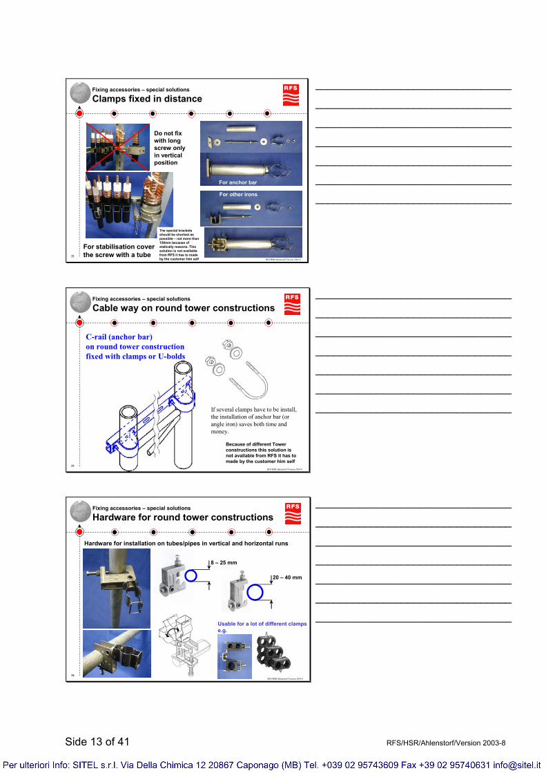
Fixing accessories – special solutions
Clamps fixed in distance
Do not fix with long screw only in vertical position
For stabilisation coverthe screw with a tube
For anchor bar
For other irons
The special brackets should be shortest as possible – not more than 150mm because of statically reasons. This solution is not available from RFS it has to made by the customer him self
________________________________
________________________________
________________________________
________________________________
________________________________
________________________________
________________________________
RFS/HSR/Ahlenstorf/Version 2003-833
Fixing accessories – special solutions
Cable way on round tower constructions
C-rail (anchor bar) on round tower constructionfixed with clamps or U-bolds
If several clamps have to be install, the installation of anchor bar (or angle iron) saves both time and money.
Because of different Tower constructions this solution is not available from RFS it has to made by the customer him self
________________________________
________________________________
________________________________
________________________________
________________________________
________________________________
________________________________
RFS/HSR/Ahlenstorf/Version 2003-834
Fixing accessories – special solutions
Hardware for round tower constructions
Hardware for installation on tubes/pipes in vertical and horizontal runs
8 – 25 mm
20 – 40 mm
Usable for a lot of different clampse.g.
________________________________
________________________________
________________________________
________________________________
________________________________
________________________________
________________________________

Side 14 of 41 RFS/HSR/Ahlenstorf/Version 2003-8
RFS/HSR/Ahlenstorf/Version 2003-835
Fixing accessories – special solutions
Hardware for round tower constructions
32
TRB-8 with screw M 8
Round membernot included
TRB-8 for installation on tubes 1“ and bigger in vertical and horizontal runs
Usable for a lot of differentclamps e.g.
________________________________
________________________________
________________________________
________________________________
________________________________
________________________________
________________________________
RFS/HSR/Ahlenstorf/Version 2003-836
Cable handling
Handle with care!
Do nothing which can deform the cablehandle with care during transportationnote correct stocking of cable and accessoriesdo not over tight the clampsdo not bend the cable to much
Make sure that the cable are clean alwaysDo not leave metallic particle, humidity dust or dirt inside the cableSeal the cable ends or connector heads
Note the installation instructions alwaysInstall all accessories e.g. connectors, grounding kits etc. inaccording to the installation instructions
Take care during transportation and installation, otherwise you will loose the good electrical
performance of the cable
________________________________
________________________________
________________________________
________________________________
________________________________
________________________________
________________________________
RFS/HSR/Ahlenstorf/Version 2003-837
Cable handling
Conserve the characteristics of the cable
If the cable is deformed (e.g. by wrong bending), damaged or particles are left inside the performance will be lost (flow rate)
Damaged
Left particle
________________________________
________________________________
________________________________
________________________________
________________________________
________________________________
________________________________
Side 15 of 41 RFS/HSR/Ahlenstorf/Version 2003-8
RFS/HSR/Ahlenstorf/Version 2003-838
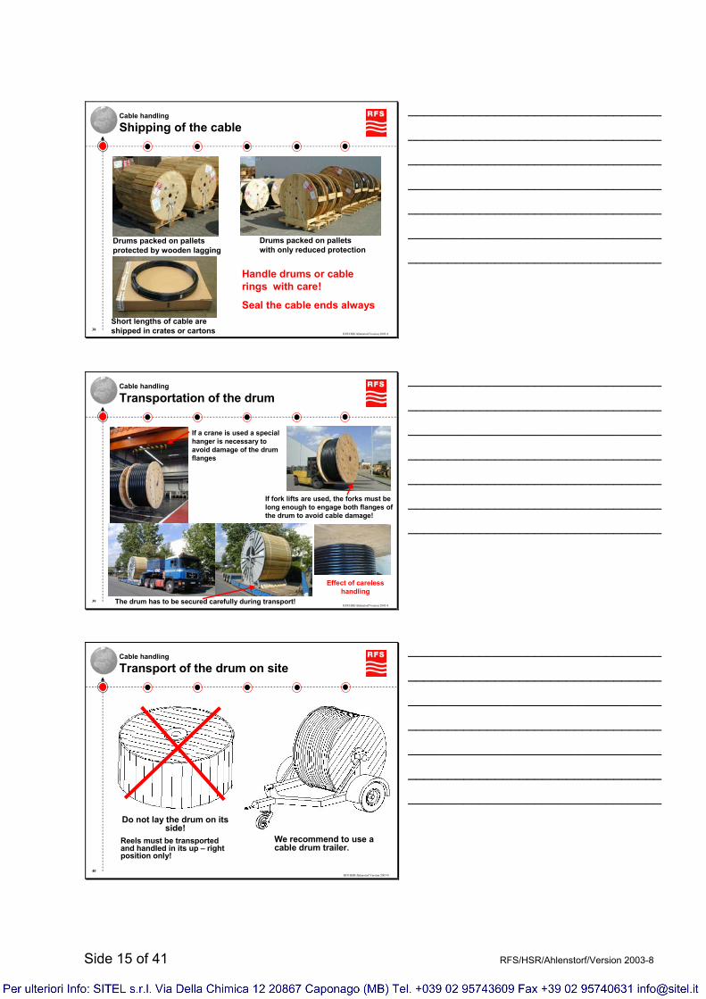
Cable handling
Shipping of the cable
Drums packed on palletswith only reduced protection
Drums packed on palletsprotected by wooden lagging
Short lengths of cable are shipped in crates or cartons
Handle drums or cable rings with care!
Seal the cable ends always
________________________________
________________________________
________________________________
________________________________
________________________________
________________________________
________________________________
RFS/HSR/Ahlenstorf/Version 2003-839
Cable handling
Transportation of the drum
If a crane is used a special hanger is necessary to avoid damage of the drum flanges
If fork lifts are used, the forks must be long enough to engage both flanges of the drum to avoid cable damage!
The drum has to be secured carefully during transport!
Effect of careless handling
________________________________
________________________________
________________________________
________________________________
________________________________
________________________________
________________________________
RFS/HSR/Ahlenstorf/Version 2003-840
Cable handling
Transport of the drum on site
Do not lay the drum on its side!
Reels must be transported and handled in its up – right position only!
We recommend to use a cable drum trailer.
________________________________
________________________________
________________________________
________________________________
________________________________
________________________________
________________________________
Side 16 of 41 RFS/HSR/Ahlenstorf/Version 2003-8
RFS/HSR/Ahlenstorf/Version 2003-841
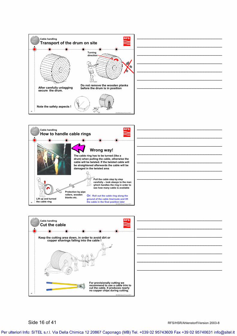
Cable handling
Transport of the drum on site
After carefully unlaggingsecure the drum.
Do not remove the wooden planks before the drum is in position
Note the safety aspects !
Turningdirection
________________________________
________________________________
________________________________
________________________________
________________________________
________________________________
________________________________
RFS/HSR/Ahlenstorf/Version 2003-842
Cable handling
How to handle cable rings
Lift up and turned the cable ring
Pull the cable step by step carefully – look always to the man which handles the ring in order to see how many cable is available
Protection by pipe rollers, wooden blanks etc.
Or: Roll out the cable ring along the ground of the cable line/route and lift the cable in the final position later
Wrong way!The cable ring has to be turned (like a drum) when pulling the cable, otherwise the cable will be twisted. If the twisted cable will be straightened afterwards the cable will be damaged in the twisted area
________________________________
________________________________
________________________________
________________________________
________________________________
________________________________
________________________________
RFS/HSR/Ahlenstorf/Version 2003-843
Cable handling
Cut the cable
For provisionally cutting we recommend to use a cable trim to cut the cable. It produces nearlyno copper chips during cutting.
Keep the cutting area down, in order to avoid dirt orcopper shavings falling into the cable !
________________________________
________________________________
________________________________
________________________________
________________________________
________________________________
________________________________

Side 17 of 41 RFS/HSR/Ahlenstorf/Version 2003-8
RFS/HSR/Ahlenstorf/Version 2003-844
Cable handling
Cut the cable
- cable will be deformed, but nearly no copper chips willbe produced during cutting. Deformed cables can be closed with hot shrink capswithout problems.
- a lot of dirt from the jacketand copper chips will be placed on the dielectric.Make sure that all particleswill be removed.
Before start the installation of the connector the cable has to be cut off again !
•Cut with cable trim:
•Cut with saw:
Cutting during hoisting/laying – Not for installation of the connectors
________________________________
________________________________
________________________________
________________________________
________________________________
________________________________
________________________________
RFS/HSR/Ahlenstorf/Version 2003-845
Cable handling
Clean the cable after cutting in depht
Deburr inner conductor Remove all edges
Remove all particles & dirt
Clean
Even outer conductor
Knocking - from the button side
Metallicparticle
Do not leave any dirt & particles inside the cable, clean specially the dielectric very well
________________________________
________________________________
________________________________
________________________________
________________________________
________________________________
________________________________
RFS/HSR/Ahlenstorf/Version 2003-846
Cable handling
Sealing of cable ends
Seal the ends of the cable !We recommend to use heat shrink caps for sealing.
Shrink the sleeve with a soft yellow flame by evenly applying a constant flame with a circular motion, beginning at the closed end.
Rough up the cable jacket with emery cloth (280 grain).
Remove emery remnants with clean cloth and clean this area of shrinking with cable cleaner.
________________________________
________________________________
________________________________
________________________________
________________________________
________________________________
________________________________
Side 18 of 41 RFS/HSR/Ahlenstorf/Version 2003-8
RFS/HSR/Ahlenstorf/Version 2003-847
Cable handling
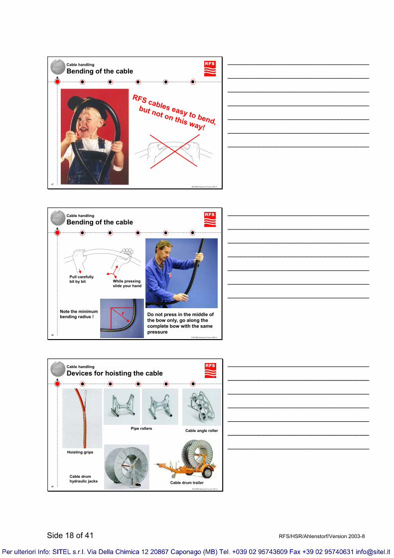
Bending of the cable
RFS cables easy to bend,
but not on this way!
________________________________
________________________________
________________________________
________________________________
________________________________
________________________________
________________________________
RFS/HSR/Ahlenstorf/Version 2003-848
Cable handling
Bending of the cable
Pull carefullybit by bit While pressing
slide your hand
Note the minimumbending radius ! r Do not press in the middle of
the bow only, go along the complete bow with the same pressure
________________________________
________________________________
________________________________
________________________________
________________________________
________________________________
________________________________
RFS/HSR/Ahlenstorf/Version 2003-849
Cable handling
Devices for hoisting the cable
Hoisting grips
Pipe rollers Cable angle roller
Cable drumhydraulic jacks Cable drum trailer
________________________________
________________________________
________________________________
________________________________
________________________________
________________________________
________________________________

Side 19 of 41 RFS/HSR/Ahlenstorf/Version 2003-8
RFS/HSR/Ahlenstorf/Version 2003-850
Cable hoisting
Hoisting grip types
Hoisting gripclosed type
This hoisting gripare to be used only forcables withoutmounted connectors.
Hoisting gripopen type
This can be used as well for cables withmounted connectors.
________________________________
________________________________
________________________________
________________________________
________________________________
________________________________
________________________________
RFS/HSR/Ahlenstorf/Version 2003-851
Cable hoisting
Installation of hoisting grip – open type
1. Place the hoisting around the cable, whereby the end with the connector shall be long enough to makethe connection to the antenna without opening the hoisting grip.Both ends with the two enclosed flexible wire strands are to beinserted in the two topmost net loops and then crosswise in the lower net loops and so up to the end (shoe close style)The meshes of the crossed wire strands shall not be smaller than the existing meshes of the hoisting grip
12. The two strand ends are to be knotted or clamped and to be secured in the net loops.The end of the hoisting grip can be fixed with tape.
2
3. Protect the cable area were the hoisting grip will be fixed to the ropefor example with the safety cloth, wool etc.
3
4. Clamp the hoisting grip with clamps to the hoisting grip or hang in a hook.
4
Note: The maximum hoisting length per hoisting grip is 70m!
_________________________________________________________________________
_________________________________________________________________________
_________________________________________________________________________
Side 20 of 41 RFS/HSR/Ahlenstorf/Version 2003-8
RFS/HSR/Ahlenstorf/Version 2003-852
Cable hoisting
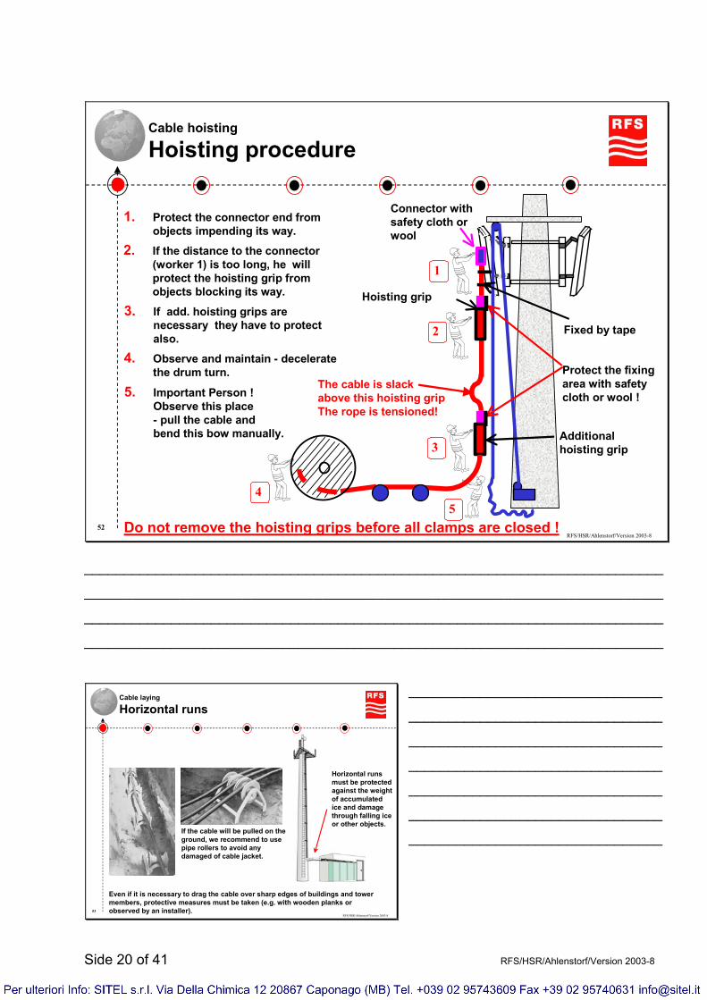
Hoisting procedure
Connector with safety cloth or wool
Hoisting grip
The cable is slackabove this hoisting gripThe rope is tensioned!
1
1. Protect the connector end from objects impending its way.
2. If the distance to the connector (worker 1) is too long, he will protect the hoisting grip from objects blocking its way.
23. If add. hoisting grips are
necessary they have to protect also.
3
4. Observe and maintain - decelerate the drum turn.
4
5. Important Person !Observe this place- pull the cable andbend this bow manually.
5Do not remove the hoisting grips before all clamps are closed !
Fixed by tape
Protect the fixing area with safety cloth or wool !
Additionalhoisting grip
_________________________________________________________________________
_________________________________________________________________________
_________________________________________________________________________
_________________________________________________________________________
RFS/HSR/Ahlenstorf/Version 2003-853
Cable laying
Horizontal runs
If the cable will be pulled on the ground, we recommend to use pipe rollers to avoid any damaged of cable jacket.
Even if it is necessary to drag the cable over sharp edges of buildings and tower members, protective measures must be taken (e.g. with wooden planks or observed by an installer).
Horizontal runs must be protected against the weight of accumulated ice and damage through falling ice or other objects.
________________________________
________________________________
________________________________
________________________________
________________________________
________________________________
________________________________
Side 21 of 41 RFS/HSR/Ahlenstorf/Version 2003-8
RFS/HSR/Ahlenstorf/Version 2003-854
Cable laying
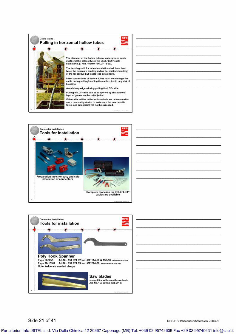
Pulling in horizontal hollow tubes
The diameter of the hollow tube (or underground cable duct) shall be at least twice the CELLFLEX® cable diameter (e.g. min. 100mm for LCF 78-50).
The bending radii for tubes installation shall be at least twice the minimum bending radius (for multiple bending) of the respective LCF cable (see data sheet).
Inter- connections of several tubes must not damage the cable during pulling/pushing the cable. - Avoid any risk of blocking.
Avoid sharp edges during pulling the LCF cable.
Pulling of LCF cable can be supported by an additional layer of grease on the cable jacket.
If the cable will be pulled with a winch, we recommend to use a measuring device to make sure the max. tensile force (see data sheet) will not be exceeded.
________________________________
________________________________
________________________________
________________________________
________________________________
________________________________
________________________________
RFS/HSR/Ahlenstorf/Version 2003-855
Connector installation
Tools for installation
Complete tool case for CELLFLEX®
cables are available
Preparation tools for easy and safe installation of connectors
________________________________
________________________________
________________________________
________________________________
________________________________
________________________________
________________________________
RFS/HSR/Ahlenstorf/Version 2003-856
Connector installation
Tools for installation
Saw bladesstraight line with smooth saw toothArt. No. 158 000 58 (Set of 10)
Poly Hook SpannerType 60-90/5 Art.No. 154 921 02 for LCF 114-50 & 158-50Type 90-155/6 Art.No. 154 921 03 for LCF 214-50Note: twice are needed always
Included in tool box
Not included in tool box
________________________________
________________________________
________________________________
________________________________
________________________________
________________________________
________________________________

Side 22 of 41 RFS/HSR/Ahlenstorf/Version 2003-8
RFS/HSR/Ahlenstorf/Version 2003-857
Connector installation
Trimming tools for SCF, UCF & LCF up to the cable size 78-50
The two in one Toolsmake connector attachment very easy
Mod.No.: TRIM-**-S (SCF cable)Mod.No.: TRIM-**-L (LCF cable)
High precisioncombination preparation tools
________________________________
________________________________
________________________________
________________________________
________________________________
________________________________
________________________________
RFS/HSR/Ahlenstorf/Version 2003-858
Connector installation
Trimming tool for LCF 114-50 & 158-50
Combination preparation toolfor LCF 114 – 50 & 158 – 50Mod.No.:TRIM-114-C06
High precision combination preparation tool
________________________________
________________________________
________________________________
________________________________
________________________________
________________________________
________________________________
RFS/HSR/Ahlenstorf/Version 2003-859
Mod.No.: TRIM-214-C01
Mod.No.: TRIM-214-C02for the new A Series of CELLFLEX® cables
Connector installation
Trimming tool for LCF cables 114-50, 158-50 & 214-50
Not usable for LCFS 114-50
________________________________
________________________________
________________________________
________________________________
________________________________
________________________________
________________________________
Side 23 of 41 RFS/HSR/Ahlenstorf/Version 2003-8
RFS/HSR/Ahlenstorf/Version 2003-860
Connector installation
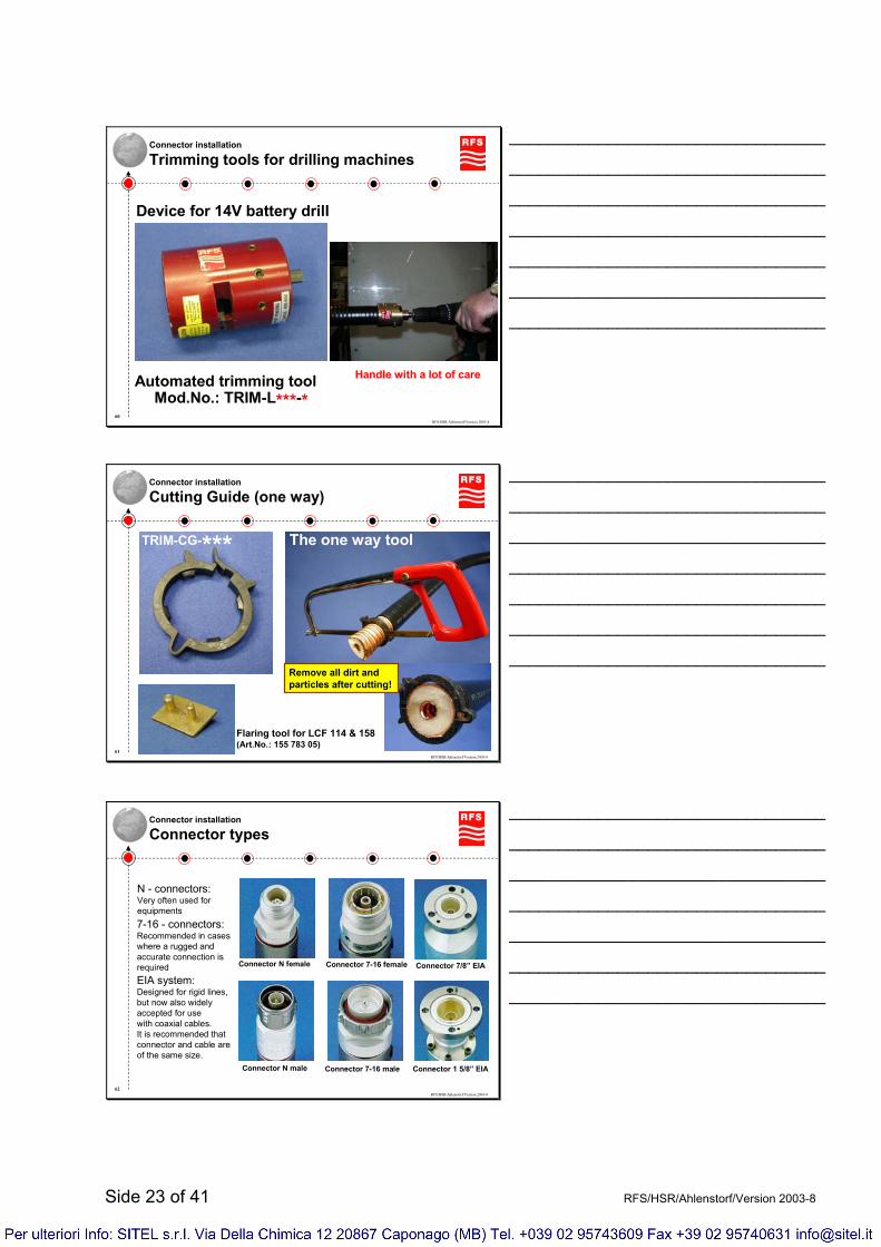
Trimming tools for drilling machines
Automated trimming toolMod.No.: TRIM-L***-*
Device for 14V battery drill
Handle with a lot of care
________________________________
________________________________
________________________________
________________________________
________________________________
________________________________
________________________________
RFS/HSR/Ahlenstorf/Version 2003-861
Connector installation
Cutting Guide (one way)
Flaring tool for LCF 114 & 158(Art.No.: 155 783 05)
TRIM-CG-*** The one way tool
Remove all dirt andparticles after cutting!
________________________________
________________________________
________________________________
________________________________
________________________________
________________________________
________________________________
RFS/HSR/Ahlenstorf/Version 2003-862
Connector installation
Connector types
Connector N female
Connector N male
N - connectors:Very often used for equipments
Connector 7-16 male
Connector 7-16 female
7-16 - connectors:Recommended in caseswhere a rugged and accurate connection isrequired Connector 7/8” EIA
Connector 1 5/8” EIA
EIA system:Designed for rigid lines, but now also widely accepted for usewith coaxial cables.It is recommended that connector and cable are of the same size.
________________________________
________________________________
________________________________
________________________________
________________________________
________________________________
________________________________

Side 24 of 41 RFS/HSR/Ahlenstorf/Version 2003-8
RFS/HSR/Ahlenstorf/Version 2003-863
Connector installation
Numbering structure for Coaxial cable connectors
________________________________
________________________________
________________________________
________________________________
________________________________
________________________________
________________________________
RFS/HSR/Ahlenstorf/Version 2003-864
Connector installationPreparation of cable
Before starting the installation:
•Cut the cable in this straightened& downward looking area min.0,2m from the end, remove all particles & dirt
•Tilt the end of cable downwards toprevent copper chips falling in tothe cable
•Straighten the cable end, approx. 1m
knocking from bottom side
________________________________
________________________________
________________________________
________________________________
________________________________
________________________________
________________________________
RFS/HSR/Ahlenstorf/Version 2003-865
All steps are shown in the installation instruction, that is always included.
Connector installationNote the installation instruction
Connectors
Sample: Part of instruction
________________________________
________________________________
________________________________
________________________________
________________________________
________________________________
________________________________

Side 25 of 41 RFS/HSR/Ahlenstorf/Version 2003-8
RFS/HSR/Ahlenstorf/Version 2003-866
Connector installationCorrect preparation & installation of connectors
Cut cable on the right place (top of corrugation) and in a right angle, therefore the use of our Trimming tool is strongly recommend.
After flaring (trimming tool recommend) remove all particles and dirt especially from the foam-dielectric. The cleaning of inner conductor is strongly recommend as well.
Make sure the connector fits in a straight line and tight him strongly (see installation instruction)
Well prepared cable, but connector is not fit in a straight line. By doing so you will lost the good electrical
performance (attenuation & impedance)
________________________________
________________________________
________________________________
________________________________
________________________________
________________________________
________________________________
RFS/HSR/Ahlenstorf/Version 2003-867
Connector installationPreparation under bad conditions
Insert the cable into building an mark the connector position
Pull the cable back to the outside and prepare the cable (preparation tools recommended)
Protect the prepared cable end (e.g. with caps or cloth) and push the cable into building by entering the wall gland very carefully
Install connector according to installation instruction
Not enough space for cable preparation – complete connector
installation from outside not possible because of to small wall
gland diameter
________________________________
________________________________
________________________________
________________________________
________________________________
________________________________
________________________________
RFS/HSR/Ahlenstorf/Version 2003-868
Connector installationConnector sealing – Sealing with Plast 2000
Injection of Plast 2000The rear part of the connector is filled with Plast 2000.This very good sealing method is described in theenclosed installation instruction.
________________________________
________________________________
________________________________
________________________________
________________________________
________________________________
________________________________
Side 26 of 41 RFS/HSR/Ahlenstorf/Version 2003-8
RFS/HSR/Ahlenstorf/Version 2003-869
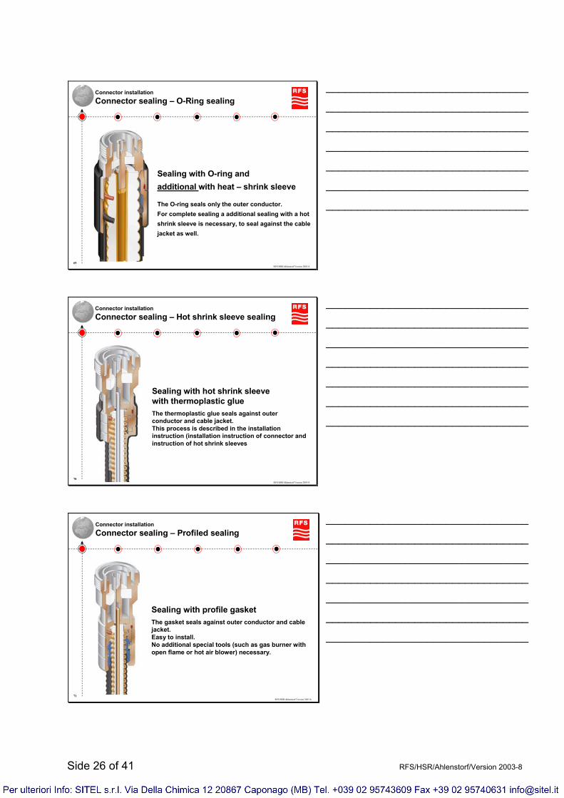
Connector installationConnector sealing – O-Ring sealing
Sealing with O-ring andadditional with heat – shrink sleeve
The O-ring seals only the outer conductor.For complete sealing a additional sealing with a hot shrink sleeve is necessary, to seal against the cablejacket as well.
________________________________
________________________________
________________________________
________________________________
________________________________
________________________________
________________________________
RFS/HSR/Ahlenstorf/Version 2003-870
Connector installationConnector sealing – Hot shrink sleeve sealing
Sealing with hot shrink sleevewith thermoplastic glueThe thermoplastic glue seals against outer conductor and cable jacket.This process is described in the installation instruction (installation instruction of connector and instruction of hot shrink sleeves
________________________________
________________________________
________________________________
________________________________
________________________________
________________________________
________________________________
RFS/HSR/Ahlenstorf/Version 2003-871
Connector installationConnector sealing – Profiled sealing
Sealing with profile gasketThe gasket seals against outer conductor and cable jacket.Easy to install.No additional special tools (such as gas burner with open flame or hot air blower) necessary.
________________________________
________________________________
________________________________
________________________________
________________________________
________________________________
________________________________
Side 27 of 41 RFS/HSR/Ahlenstorf/Version 2003-8
RFS/HSR/Ahlenstorf/Version 2003-872
Connector installationConnector sealing – Sealing with Plast 2000
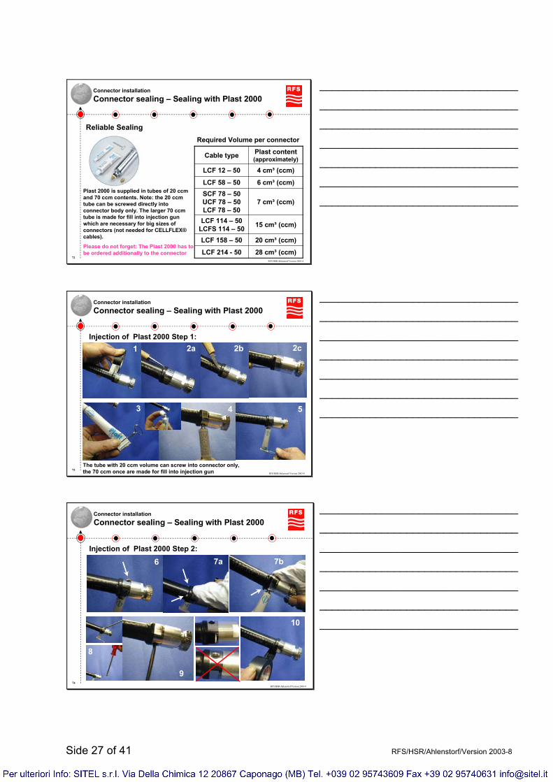
28 cm³ (ccm)LCF 214 - 50
20 cm³ (ccm)LCF 158 – 50
15 cm³ (ccm)LCF 114 – 50LCFS 114 – 50
7 cm³ (ccm)SCF 78 – 50UCF 78 – 50LCF 78 – 50
6 cm³ (ccm)LCF 58 – 50
4 cm³ (ccm)LCF 12 – 50
Plast content(approximately)Cable type
Required Volume per connector
Reliable Sealing
Plast 2000 is supplied in tubes of 20 ccm and 70 ccm contents. Note: the 20 ccm tube can be screwed directly into connector body only. The larger 70 ccm tube is made for fill into injection gun which are necessary for big sizes of connectors (not needed for CELLFLEX®cables).
Please do not forget: The Plast 2000 has to be ordered additionally to the connector
________________________________
________________________________
________________________________
________________________________
________________________________
________________________________
________________________________
RFS/HSR/Ahlenstorf/Version 2003-873
Connector installationConnector sealing – Sealing with Plast 2000
Injection of Plast 2000 Step 1:1 2a 2b 2c
3 4 5
The tube with 20 ccm volume can screw into connector only,the 70 ccm once are made for fill into injection gun
________________________________
________________________________
________________________________
________________________________
________________________________
________________________________
________________________________
RFS/HSR/Ahlenstorf/Version 2003-874
Connector installationConnector sealing – Sealing with Plast 2000
Injection of Plast 2000 Step 2:
6 7a 7b
8
9
10
________________________________
________________________________
________________________________
________________________________
________________________________
________________________________
________________________________
Side 28 of 41 RFS/HSR/Ahlenstorf/Version 2003-8
RFS/HSR/Ahlenstorf/Version 2003-875
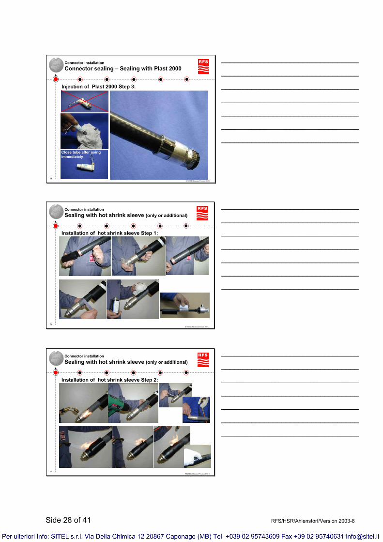
Connector installationConnector sealing – Sealing with Plast 2000
Injection of Plast 2000 Step 3:
Close tube after using immediately
________________________________
________________________________
________________________________
________________________________
________________________________
________________________________
________________________________
RFS/HSR/Ahlenstorf/Version 2003-876
Connector installationSealing with hot shrink sleeve (only or additional)
Installation of hot shrink sleeve Step 1:
________________________________
________________________________
________________________________
________________________________
________________________________
________________________________
________________________________
RFS/HSR/Ahlenstorf/Version 2003-877
Connector installationSealing with hot shrink sleeve (only or additional)
Installation of hot shrink sleeve Step 2:
________________________________
________________________________
________________________________
________________________________
________________________________
________________________________
________________________________

Side 29 of 41 RFS/HSR/Ahlenstorf/Version 2003-8
RFS/HSR/Ahlenstorf/Version 2003-878
Connector installationSealing with hot shrink sleeve (only or additional)
Installation of hot shrink sleeve good and bad examples
________________________________
________________________________
________________________________
________________________________
________________________________
________________________________
________________________________
RFS/HSR/Ahlenstorf/Version 2003-879
Connection installationProtection of connector head
If the connector will not be connect to antenna or equipment after the attachment of the connector soon, it is strongly recommended to protect the connector head, e.g. with plastic caps, to avoid any dirt or water
Protection of humidity & dirt Protection of
dust only
________________________________
________________________________
________________________________
________________________________
________________________________
________________________________
________________________________
RFS/HSR/Ahlenstorf/Version 2003-880
Connection installationMating of connector head
The connection has to be done with tools (not only by hand), to make sure that the connection is absolutely water tight.
The O-ring inside the connector will seal this connection absolutely.No additional sealing is necessary.
Min. & max. torques of mating: N = 6…8 Nm / 7-16 = 25…..30 Nm
________________________________
________________________________
________________________________
________________________________
________________________________
________________________________
________________________________
Side 30 of 41 RFS/HSR/Ahlenstorf/Version 2003-8
RFS/HSR/Ahlenstorf/Version 2003-881
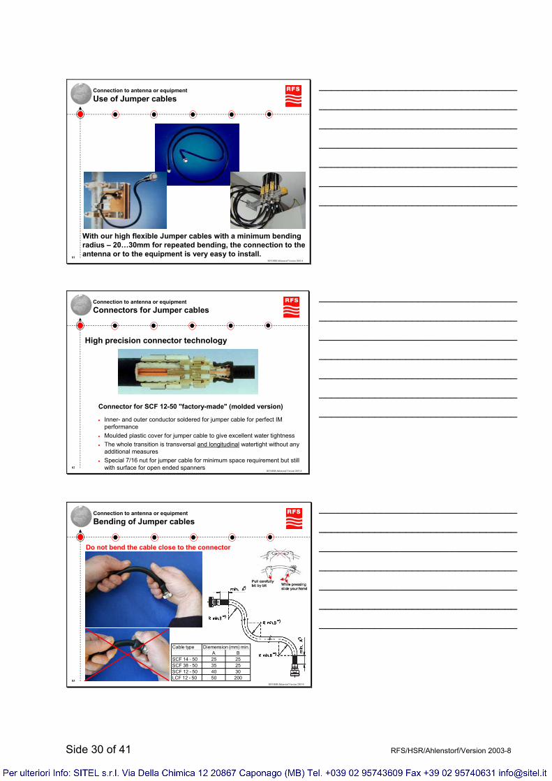
Connection to antenna or equipmentUse of Jumper cables
With our high flexible Jumper cables with a minimum bending radius – 20…30mm for repeated bending, the connection to the antenna or to the equipment is very easy to install.
________________________________
________________________________
________________________________
________________________________
________________________________
________________________________
________________________________
RFS/HSR/Ahlenstorf/Version 2003-882
Connection to antenna or equipmentConnectors for Jumper cables
Connector for SCF 12-50 "factory-made" (molded version)
• Inner- and outer conductor soldered for jumper cable for perfect IM performance
• Moulded plastic cover for jumper cable to give excellent water tightness• The whole transition is transversal and longitudinal watertight without any
additional measures• Special 7/16 nut for jumper cable for minimum space requirement but still
with surface for open ended spanners
High precision connector technology
________________________________
________________________________
________________________________
________________________________
________________________________
________________________________
________________________________
RFS/HSR/Ahlenstorf/Version 2003-883
Connection to antenna or equipmentBending of Jumper cables
Cable type Diemension (mm) min.A B
SCF 14 - 50 25 25SCF 38 - 50 35 25SCF 12 - 50 40 30LCF 12 - 50 50 200
Do not bend the cable close to the connector
________________________________
________________________________
________________________________
________________________________
________________________________
________________________________
________________________________
Side 31 of 41 RFS/HSR/Ahlenstorf/Version 2003-8
RFS/HSR/Ahlenstorf/Version 2003-884
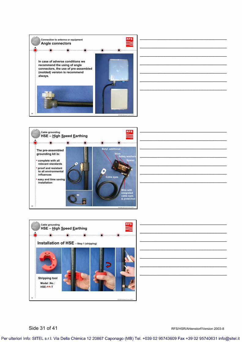
Connection to antenna or equipmentAngle connectors
In case of adverse conditions we recommend the using of angle connectors, the use of pre-assembled (molded) version is recommend always.
________________________________
________________________________
________________________________
________________________________
________________________________
________________________________
________________________________
RFS/HSR/Ahlenstorf/Version 2003-885
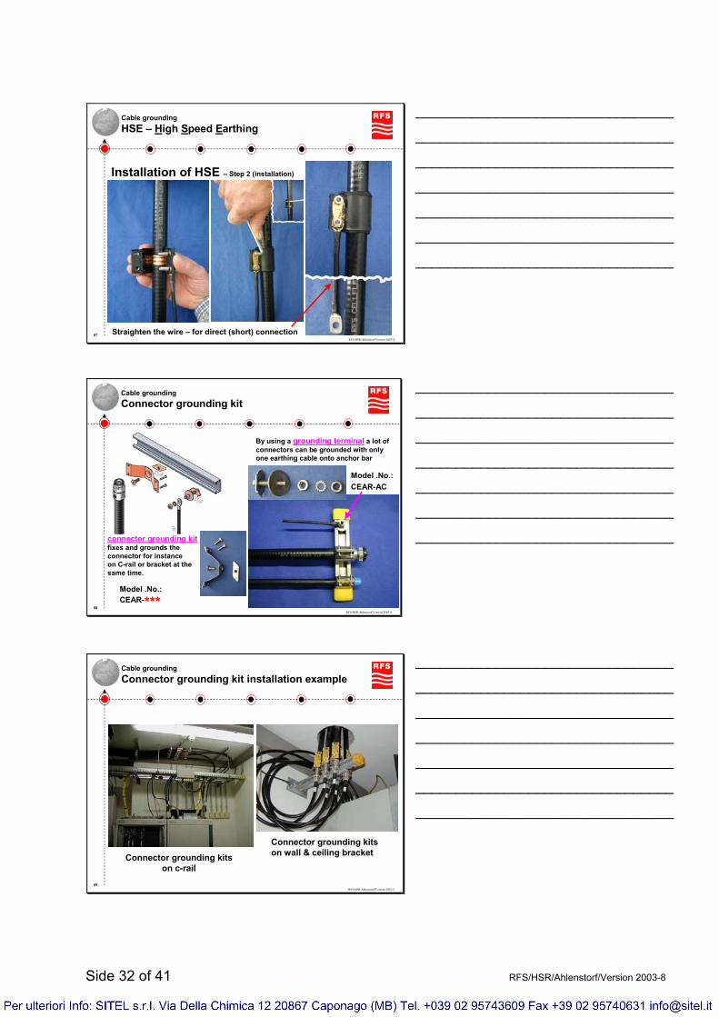
Cable groundingHSE – High Speed Earthing
The pre-assembled grounding kit is:
• complete with all relevant standards
• proof and resistant to all environmentalinfluences
• easy and time saving installation
Wire withintegratedcable eyes& protection
Cable eyes
Butyl, additional
ShimSafety washers
Spacer
________________________________
________________________________
________________________________
________________________________
________________________________
________________________________
________________________________
RFS/HSR/Ahlenstorf/Version 2003-886
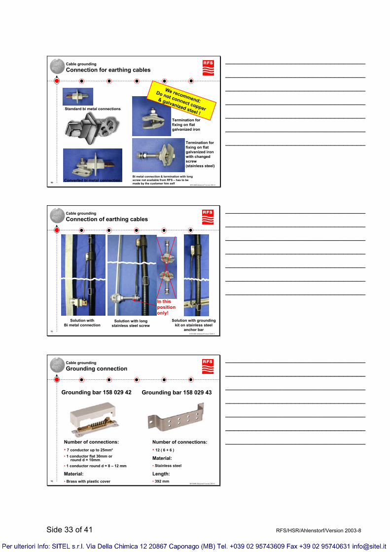
Cable groundingHSE – High Speed Earthing
Stripping toolModel .No.:HSE-**-T
Installation of HSE – Step 1 (stripping)
________________________________
________________________________
________________________________
________________________________
________________________________
________________________________
________________________________
Side 32 of 41 RFS/HSR/Ahlenstorf/Version 2003-8
RFS/HSR/Ahlenstorf/Version 2003-887
Cable groundingHSE – High Speed Earthing
Straighten the wire – for direct (short) connection
Installation of HSE – Step 2 (installation)
________________________________
________________________________
________________________________
________________________________
________________________________
________________________________
________________________________
RFS/HSR/Ahlenstorf/Version 2003-888
Cable groundingConnector grounding kit
By using a grounding terminal a lot of connectors can be grounded with only one earthing cable onto anchor bar
Model .No.:CEAR-AC
Model .No.:CEAR-***
connector grounding kitfixes and grounds theconnector for instanceon C-rail or bracket at thesame time.
________________________________
________________________________
________________________________
________________________________
________________________________
________________________________
________________________________
RFS/HSR/Ahlenstorf/Version 2003-889
Cable groundingConnector grounding kit installation example
Connector grounding kitson c-rail
Connector grounding kitson wall & ceiling bracket
________________________________
________________________________
________________________________
________________________________
________________________________
________________________________
________________________________
Side 33 of 41 RFS/HSR/Ahlenstorf/Version 2003-8
RFS/HSR/Ahlenstorf/Version 2003-890
Cable groundingConnection for earthing cables
Converted bi metal connection
Standard bi metal connections
Termination for fixing on flat galvanized ironwith changedscrew(stainless steel)
Termination for fixing on flat galvanized iron
We recommend:
Do not connect copper
& galvanized steel !
Bi metal connection & termination with long screw not available from RFS – has to be made by the customer him self
________________________________
________________________________
________________________________
________________________________
________________________________
________________________________
________________________________
RFS/HSR/Ahlenstorf/Version 2003-891
Cable groundingConnection of earthing cables
Solution with grounding kit on stainless steel
anchor bar
In thispositiononly!
Solution withBi metal connection
Solution with long stainless steel screw
________________________________
________________________________
________________________________
________________________________
________________________________
________________________________
________________________________
RFS/HSR/Ahlenstorf/Version 2003-892
Cable groundingGrounding connection
Grounding bar 158 029 43Grounding bar 158 029 42
Number of connections:• 7 conductor up to 25mm²• 1 conductor flat 30mm or
round d = 10mm• 1 conductor round d = 8 – 12 mm
Material:• Brass with plastic cover
Number of connections:• 12 ( 6 + 6 )
Material:• Stainless steel
Length:• 392 mm
________________________________
________________________________
________________________________
________________________________
________________________________
________________________________
________________________________

Side 34 of 41 RFS/HSR/Ahlenstorf/Version 2003-8
RFS/HSR/Ahlenstorf/Version 2003-893
Cable groundingEMP protection – gas type
Features• Built-in gas capsule• N and 7-16 connectors• DC-path available• Breakdown voltages can be
selected via capsule 90V, 230V and 350V
• Regular inspection recommended• Broadband applications• Receive only applications• Transmit application limited• Residual voltage app. 80V• Housing options
________________________________
________________________________
________________________________
________________________________
________________________________
________________________________
________________________________
RFS/HSR/Ahlenstorf/Version 2003-894
Cable groundingEMP protection – λ/4 stub type
Features• DC short circuit via λ/4-stub• N and 7-16 connectors• DC-path not available• No serviceable parts• Narrowband models offer
premium VSWR• Transmit application• Residual voltage current
dependent• Housing options
________________________________
________________________________
________________________________
________________________________
________________________________
________________________________
________________________________
RFS/HSR/Ahlenstorf/Version 2003-895
Cable groundingGrounding philosophy – Recommended grounding points
Install earthing kits only
where the cable runs
straight !
Or connector grounding
ApproximatelyEvery 20m
Antennas has tobe grounded!
In the first straight section
Before penetratinghigher LPZ
Best place
Connectorgrounding
EMP devices Acceptable place
HSE
Before entering buildings
Before changing directions
________________________________
________________________________
________________________________
________________________________
________________________________
________________________________
________________________________
Side 35 of 41 RFS/HSR/Ahlenstorf/Version 2003-8
RFS/HSR/Ahlenstorf/Version 2003-896
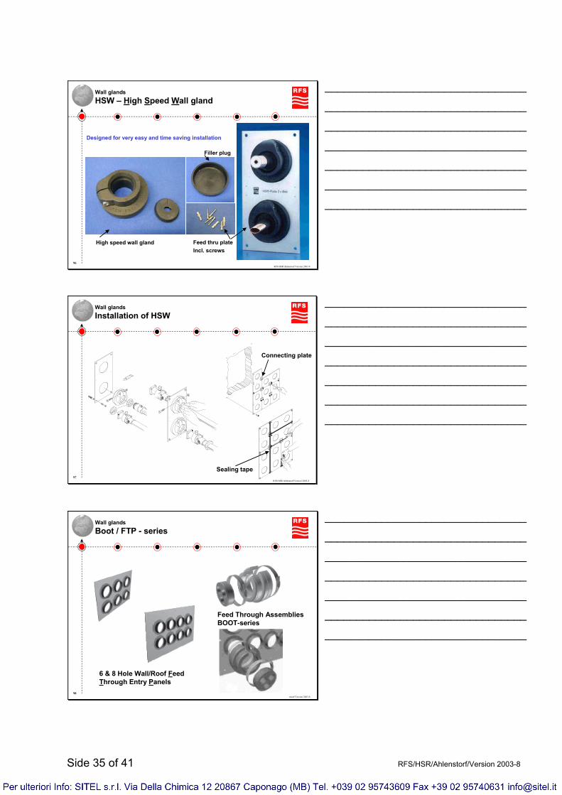
Wall glandsHSW – High Speed Wall gland
Designed for very easy and time saving installation
Feed thru plateIncl. screws
High speed wall gland
Filler plug
________________________________
________________________________
________________________________
________________________________
________________________________
________________________________
________________________________
RFS/HSR/Ahlenstorf/Version 2003-897
Wall glandsInstallation of HSW
Dichtmasse
Sealant
Connecting plate
Dic
h tm
a sse
Sea
lan t
Sealing tape
________________________________
________________________________
________________________________
________________________________
________________________________
________________________________
________________________________
RFS/HSR/Ahlenstorf/Version 2003-898
Wall glandsBoot / FTP - series
6 & 8 Hole Wall/Roof Feed Through Entry Panels
Feed Through AssembliesBOOT-series
________________________________
________________________________
________________________________
________________________________
________________________________
________________________________
________________________________

Side 36 of 41 RFS/HSR/Ahlenstorf/Version 2003-8
RFS/HSR/Ahlenstorf/Version 2003-899
Wall glandsSingle wall gland
Easy for existing cut of wall plates or if the cable has to enter the wall in a very long length (means a big hole into wall is needed for installation – this will be closed with separate plates after pulling of the cable)
________________________________
________________________________
________________________________
________________________________
________________________________
________________________________
________________________________
RFS/HSR/Ahlenstorf/Version 2003-8100
Wall glandsSIGMAFORM
hot shrink partO - ringWall - plate
Inner partwith thread
5 different sizes available 70,0 – 36,0 mm85,0 mmCES 540,0 – 19,0 mm51,0 mmCES 428,0 – 13,0 mm35,0 mmCES 319,0 – 6,0 mm25,5 mmCES 214,0 – 3,0 mm25,5 mmCES 1
Shrinkingzone Ø
Requireddrilling Ø
Part No.
________________________________
________________________________
________________________________
________________________________
________________________________
________________________________
________________________________
RFS/HSR/Ahlenstorf/Version 2003-8101
Wall glandsSystem Brattberg & Roxtec
Wall glands with highfire protection
Inlets inter-changeable
________________________________
________________________________
________________________________
________________________________
________________________________
________________________________
________________________________
Side 37 of 41 RFS/HSR/Ahlenstorf/Version 2003-8
RFS/HSR/Ahlenstorf/Version 2003-8102
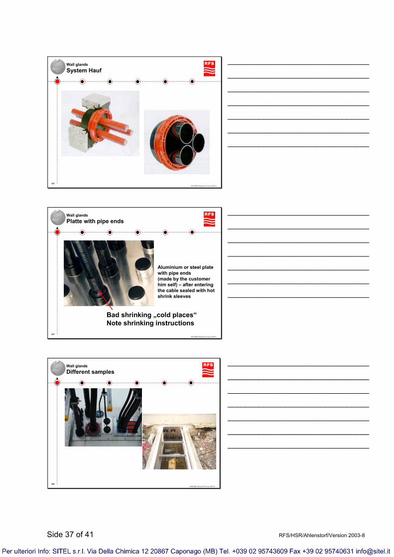
Wall glandsSystem Hauf
________________________________
________________________________
________________________________
________________________________
________________________________
________________________________
________________________________
RFS/HSR/Ahlenstorf/Version 2003-8103
Wall glandsPlatte with pipe ends
Aluminium or steel plate with pipe ends(made by the customer him self) – after entering the cable sealed with hot shrink sleeves
Bad shrinking „cold places“Note shrinking instructions
________________________________
________________________________
________________________________
________________________________
________________________________
________________________________
________________________________
RFS/HSR/Ahlenstorf/Version 2003-8104
Wall glandsDifferent samples
________________________________
________________________________
________________________________
________________________________
________________________________
________________________________
________________________________

Side 38 of 41 RFS/HSR/Ahlenstorf/Version 2003-8
RFS/HSR/Ahlenstorf/Version 2003-8105
Additional sealingHot shrink sleeve & tapes sealing
Sealing with hot shrink sleeve+ absolute water proofed sealing
(if correct installed!)+ stabilisation of connection- not easy to install
(specially by bad wetter conditions)- hard to remove- hot air gun or gas burner needed- easy to make mistakes during
installation
123
________________________________
________________________________
________________________________
________________________________
________________________________
________________________________
________________________________
RFS/HSR/Ahlenstorf/Version 2003-8106
Additional sealingWeatherproofing Kit (butyl & electrical tapes)
Sealing with sealing tapes+ no additional tools necessary+ not necessary to open the connection- not easy to install (specially by bad
wetter conditions)- perfect sealing depends on correct
installation- easy to make mistakes during
installation (e.g. touch with fingers on the tape in sealing areas)
- if more than one cable runs consist close together very difficult to install
min. 50mm min. 50mmmin. 50mm
min. 50mm
1
2
3
4
Do not Pull the tape during the last few turns otherwise the tape will unravel
________________________________
________________________________
________________________________
________________________________
________________________________
________________________________
________________________________
RFS/HSR/Ahlenstorf/Version 2003-8107
Additional sealingSelf – fusing tape
Sealing with sealing tapes+ no additional tools necessary+ not necessary to open the connection- not easy to install (specially by bad
wetter conditions)- perfect sealing depends on correct
installation- easy to make mistakes during
installation (e.g. touch with fingers on the tape in sealing areas)
- if more than one cable runs consist close together very difficult to install
________________________________
________________________________
________________________________
________________________________
________________________________
________________________________
________________________________

Side 39 of 41 RFS/HSR/Ahlenstorf/Version 2003-8
RFS/HSR/Ahlenstorf/Version 2003-8108
Additional sealingCold Shrink Kit
The fast fit cold shrink kitsimple & very fast installationno tools requiredno heat requiredtight sealingwater-proof protectioneasy to remove
1. Slide the cold shrink tube over thecable and set foam strips – note the wrapping direction
2. Join the connectors and place the tube(in wintertime it is recommended to stocking the tube on a warm place until using)
3. Shrink the tube by pulling the core by hand 1 2 3
________________________________
________________________________
________________________________
________________________________
________________________________
________________________________
________________________________
RFS/HSR/Ahlenstorf/Version 2003-8109
Installation examplesInside buildings
Coupling networkconnection with
SCF Jumper cables
Cable/connector fixingwith connector grounding
kit on wall & ceiling bracket
________________________________
________________________________
________________________________
________________________________
________________________________
________________________________
________________________________
RFS/HSR/Ahlenstorf/Version 2003-8110
Installation examplesOn the roof of building
Cable placed in cable trays and on pipes
Cables fixed on concrete blocksincluding C-Rails
________________________________
________________________________
________________________________
________________________________
________________________________
________________________________
________________________________

Side 40 of 41 RFS/HSR/Ahlenstorf/Version 2003-8
RFS/HSR/Ahlenstorf/Version 2003-8111
Installation examplesOutside buildings
C-rails fixed to adjusted flat iron
C-rails fixed to the wall
________________________________
________________________________
________________________________
________________________________
________________________________
________________________________
________________________________
RFS/HSR/Ahlenstorf/Version 2003-8112
Installation examplesOn towers
With LCF cableto the TMA
________________________________
________________________________
________________________________
________________________________
________________________________
________________________________
________________________________
RFS/HSR/Ahlenstorf/Version 2003-8113
Installation examplesBad installation example
Nearly nothing is well done!• Feeder cables not correctly fixed (must be
fixed on the end as well, Jumper cable has to fixed also)
• Jumper cable is bended to strong and to close to the connector (by doing so the cable will be damaged in a short time when moving due to wind)
• Cables laying in front of the antenna (that will influence the signal characteristic of the antenna).
• Grounding kits installed in a bended cable run (cable damaging and humidity)
• Grounding cables not in direct shortest direction to the ground (in case of lightning the voltage will damage some things)
• The grounding connection to the tower is corrosive because of the connection cooper to galvanized steel
________________________________
________________________________
________________________________
________________________________
________________________________
________________________________
________________________________

Side 41 of 41 RFS/HSR/Ahlenstorf/Version 2003-8
RFS/HSR/Ahlenstorf/Version 2003-8114
Thank you for Listening
Wherever you have to work, RFS wishes you a complete success at your work.
Enjoy the panorama from towers and buildings without accident.
If you have any questions, please don’t hesitate to ask us.


