Embed Size (px)
Citation preview
Simple, quick and safe poweredportable access lift, perfect
for construction site andmaintenance applications.
Code 87203
Operating & Safety Guide 501
504/01501/01
©HSS Hire Service Group Ltd 2009 No. 504/01 Group O�ce: Oakland House, 76 Talbot Rd. Manchester
M16 0PQ Web Site: http://www.hss.com
If you have any suggestions to enable us to improve theinformation within this guide please e-mail your comments or
write to the Safety Guide Manager at the address below e-mail: [email protected]
The law requires that personnel using this type of equipmentmust be competent and quali�ed to do so. Training is available at
HSS Training Solutions 0845 766 7799
EQUIPMENT CARE
FINISHING OFF
Never push the equipment beyond its design limits. If itwill not do what you want with reasonable ease and speed,assume you have the wrong tool for the job. Contact yourlocal HSS Hire for advice.Keep the equipment clean, you will �nd this less of achore if you clean it regularly, rather than wait until the endof the hire period.When not in use, store the equipment somewhere clean,dry and safe from thieves and unauthorised users.
Lower the cage and exit. Turn the unit o� and as a safetyprecaution, press red STOP button.Collect all parts together and give them a �nal clean upready for return, to your local HSS Hire.
Check structure (e.g. damage, cracks,corrosion, abrasion, welds, connections)
Check platform (floor, rails, handrailsockets).
Check castors (smooth movement,damage).
Check brakes.
Check oil leaks.
Ensure battery is fully loaded.
Ensure raise and lower functions operatewell.
Check emergency stop and loweringfunctions.
Check safety decals.
1.
2.
3.
4.
5.
6.
7.
8.
9.
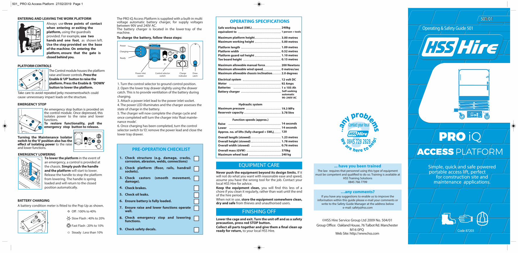
The PRO iQ Access Platform is supplied with a built-in multivoltage automatic battery charger, for supply voltagesbetween 90V and 240V AC. The battery charger is located in the lower tray of themachine.To charge the battery, follow these steps:
501_ PRO iQ Access Platform 27/02/2019 Page 1
PRO iQACCESS PLATFORM
ENTERING AND LEAVING THE WORK PLATFORMAlways use three points of contact when entering or exiting the platform, using the guardrails provided. For example, use two hands and one foot, as shown left. Use the step provided on the base of the machine. On entering the platform, ensure that the gate is closed behind you.
PLATFORM CONTROLSThe Control module houses the platform raise and lower controls. Press the Enable & ‘UP’ button to raise the platform. Press the Enable & ‘DOWN’ button to lower the platform.
Take care to avoid repeated jerky movementswhich could cause unnecessary impact loads on the structure.
EMERGENCY STOPAn emergency stop button is provided onthe control module. Once depressed, thisisolates power to the raise and lowerfunctions. To restore functionality, pull theemergency stop button to release.
Turning the Maintenance Isolatorswitch to the ‘0’ position also has thee�ect of isolating power to the raiseand lower functions.
EMERGENCY LOWERINGTo lower the platform in the event of an emergency, a control is provided at the chassis. Simply push the handle and the platform will start to lower. Release the handle to stop the platform from lowering. The handle is spring loaded and will return to the closed position automatically.
Safe working load (SWL)equivalent to
Overall mass (GVW) Maximum wheel load
Maximum platform height Maximum working height
Platform length Platform width Platform guard rail height Toe board height
Maximum allowable manual force Maximum allowable wind speed Maximum allowable chassis inclination
Electrical system Motor Batteries Battery charger
Hydraulic system Maximum pressure Reservoir capacity
Function speeds (approx.) Raise Lower Approx. no. of lifts (fully charged + SWL)
Overall length (stowed) Overall height (stowed) Overall width (stowed)
240kg 1 person + tools
3.00 metres 5.00 metres
1.09 metres 0.52 metres 1.10 metres 0.15 metres
200 Newtons 0 metres/sec 2.0 degrees
12 volt DC 92 Amps 1 x 10⁵ Ah Self-seeking automatic 90–240V AC
19.3 MPa3.78 litre
14 seconds 14 seconds 120
1.23 metres 1.78 metres 0.76 metres
370kg 240 kg
BATTERY CHARGINGA battery condition meter is fitted to the Pop Up as shown.
O� : 100% to 40%
Slow Flash : 40% to 20%
Fast Flash : 20% to 10%
Steady : Less than 10%
1. Turn the control selector to ground control position.2. Open the lower tray drawer slightly using the drawer catch. This is to provide ventilation of the battery during charging.3. Attach a power inlet lead to the power inlet socket.4. The power LED illuminates and the charger assesses the state of charge in the battery.5. The charger will now complete the charge cycle and once completed will turn the charger into ‘�oat mainte-nance mode’.6. Once charging has been completed, turn the control selector switch to ‘O’, remove the power lead and close the lower tray drawer.
Power
Charging
Ready
Control selectorswitch
Chargeindicator
Drawcatch
Power inletsocket
Never manoeuvre the PRO iQ whilst in its elevatedposition, as this may cause instability.Never enter or exit the platform unless the platform is inthe lowered and transport position.Never apply external side loads to the platform orscissor structure.
snosrep woll a reveN at ground level to operate thecontrols whilst the platform is occupied (unless in anemergency situation).
For advice on the safety and suitability of thisequipment contact your local HSS Hire.There is a serious risk of personal injury if you do notfollow all instructions laid down in this guide.The hirer has a responsibility to ensure that allnecessary risk assessments have been completed priorto the use of this equipment.This equipment should only be used by an operatorwho has been deemed competent to do so by his/heremployer.This equipment is designed to be used by an able bodied,competent adult who has read and understood theseinstructions. Anyone with either a temporary or permanentdisability should seek expert advice before using it.Keep children, animals and bystanders away from thework area. Cordon o� a NO GO area using cones andeither barriers or tape, available for hire from your localHSS Hire.
Never use this equipment if you are ill, feelingtired, or under the in�uence of alcohol or
drugs.Wear practical, protective clothing,gloves, footwear and a protective hard
hat. Avoid loose garments and jewellery that could catch inmoving parts, tie back long hair.Do not work near �ammable gases or liquids, petrol orpaint thinner fumes for example. Keep combustiblematerials at a safe distance – at least 5m. Make sure you know how to switch this equipment OFFbefore you switch it ON in case you get into di�culty. Make sure you know how to operate this equipmentsafely and are aware of its limitations before you use it. Make sure that everyone is warned of what you aredoing.This machine is designed for internal use only. If workingin a building which has large openings where wind gustsoccur, DO NOT USE THE MACHINE. The maximum number of occupants must not exceedone. Never use the lift near overhead power lines or similarhazards.Never exceed the equipment’s safe working load of240Kg.Never operate the equipment alone. Ensure a competent adult is always within shouting range to operate themanual descent system or come to your aid if anythingshould go wrong.Never use the platform as a goods lift or crane.Never try to move the platform on its castors whenelevated.Never extend the height of the platform by using boxes,steps ladders etc.Never modify the PRO iQ Access Platform in any waywithout the full approval of the manufacturer.Never manoeuvre the platform on an inclined surfaceotherwise it may become uncontrollable.
GENERAL SAFETY
ELECTRICAL SAFETY
GETTING STARTED
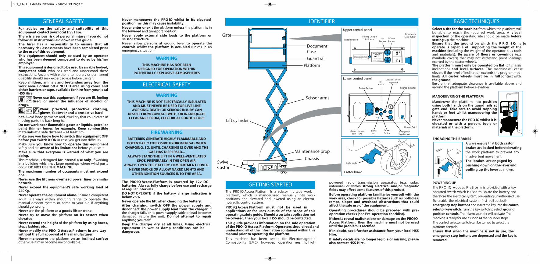
IDENTIFIER
THIS MACHINE HAS NOT BEEN DESIGNED FOR OPERATION WITHIN
POTENTIALLY EXPLOSIVE ATMOSPHERES
The PRO iQ Access Platform is a scissor lift type workplatform, which is manoeuvred manually into workpositions and elevated and lowered using an electro-hydraulic control system. PRO iQ Access Platform must not be used inapplications or for uses outside of the scope of thisoperating safety guide. Should a certain application notbe covered, then your local HSS should be contacted.This guide provides information on the safe operationof the PRO iQ Access Platform. Operators should read and understand all of the information contained within thismanual prior to operating the platform.This machine has been tested for ElectromagneticCompatibility (EMC) however, operation near to high
BASIC TECHNIQUESSelect a site for the machine from which the platform willbe able to reach the required work area. A visualinspection of the operating site should be made beforesetting up the machine.Ensure that the ground on which the P R O i Q is tooperate is capable of supporting the weight of themachine (including the weight of the operator plus toolsand materials). Be aware of floors or coverings (e.g.manhole covers) that may not withstand point loadingsexerted by the castor wheels.The platform must only be operated on flat (0º chassisinclination) and level surfaces. The machine will ceaseelevate if the level of inclination exceeds the programmedlimits. All castor wheels must be in full contact withthe ground.Ensure that adequate clearance is available above andaround the platform before elevation.
THIS MACHINE IS NOT ELECTRICALLY INSULATEDAND MUST NEVER BE USED FOR LIVE LINE
WORKING. DEATH OR SERIOUS INJURY CAN RESULT FROM CONTACT WITH, OR INADEQUATECLEARANCE FROM, ELECTRICAL CONDUCTORS
BATTERIES GENERATE HIGHLY FLAMMABLE AND POTENTIALLY EXPLOSIVE HYDROGEN GAS WHEN
CHARGING, SO, UNTIL CHARGING IS OVER AND THEGAS HAS DISPERSED...
ALWAYS STAND THE LIFT IN A WELL-VENTILATEDSPOT, PREFERABLY IN THE OPEN AIR.
ALWAYS OPEN THE BATTERY COMPARTMENT COVER. NEVER SMOKE OR ALLOW NAKED LIGHTS AND
OTHER IGNITION SOURCES INTO THE AREA.
powered radio transmission apparatus (e.g. radar,antennae) or within strong electrical and/or magneticfields may a�ect some features of this product.Before operating platform familiarise yourself with thework area, check for possible hazards such as potholes,ramps, slopes and overhead obstructions that coulda�ect the safe use of the equipment.Operating procedures should be preceded with pre-operation checks (see Pre-operation checklist).If checks reveal malfunctions or damage on the PRO iQAccess Platform, then the machine must not be useduntil the problem is rectified.If in doubt, seek further assistance from your local HSSHire. If safety decals are no longer legible or missing, pleasealso contact HSS Hire.
ENGAGING THE BRAKES
MANOEUVRING THE PLATFORMManoeuvre the platform into positionusing both hands on the guard rails atgate end. Take care to avoid trappinghands or feet whilst manoeuvring theplatform. Never manoeuvre the PRO iQ whilst it iselevated or with a person, tools ormaterials in the platform.
POWERING UPThe PRO iQ Access Platform is powered by 12v DCbatteries. Always fully charge before use and rechargeat regular intervals.DO NOT OPERATE if the battery charge indication isbelow 25%Never operate the lift when charging the battery. After charging, switch OFF the power supply anddisconnect the power supply lead from the charger. Ifthe charger fails, or its power supply cable or lead becomesdamaged, return the unit. Do not attempt to repairanything yourself.Keep the charger dry at all times. Using electricalequipment in wet or damp conditions can bedangerous.
501_PRO iQ Acess Platform 27/02/2019 Page 2
Gate
Guard rail
SwivelCastor
Lift cylinder
Maintenance prop
Platform
Scissor arms
Chassis
Document Case
Castor brake
Lower control panel
Upper control panel
Enable ButtonBattery Charge
Indicator UP Button
EmergencyStop Button
Brake pedal
Charger powerinlet (16A)
Charge Indicator
EmergencyStop Button
Enable Button
DOWNButton
Drawer Catch
Control SelectorKeyswitchUP
Button
Always ensure that both castor brakes are locked before elevating the work platform to prevent any in advertent movement. The brakes are engaged by pushing down on the lever and pulling up the lever as shown.
The PRO iQ Access Platform is provided with a key operated switch which is used to isolate the battery and therefore the electrical system, preventing unauthorised use. To enable the electrical system, first pull out both emergency stop buttons and insert the key into the control selector keyswitch. Turn the key switch to select ground position controls. The alarm sounder will activate. The machine is ready for use as soon as the sounder stops.The control selector switch can be turned to select theplatform controls.Ensure that when the machine is not in use, the emergency stop buttons are depressed and the key is removed.
DOWN Button
PowerLED