Embed Size (px)
DESCRIPTION
Citation preview

1
ASSOCIATED
ALTERNATOR - STARTER TESTERModel 8600 1/2 HP
8601 1 HP
OPERATION AND MAINTENANCE MANUALIMPORTANT SAFETY INSTRUCTIONS
SAVE THESE INSTRUCTIONS. This manual contains important safety and operating instructions for thealternator/starter tester you have purchased. You may need to refer to these instructions at a later date.
CAUTION: THE WEIGHT OF THE INDIVIDUAL COMPONENTS AND/OR THE ASSEMBLED UNIT MAY EXCEEDTHE SAFE LIMIT THAT MAY BE LIFTED BY ONE INDIVIDUAL. EXTREME CARE SHOULD BEEXERCISED WHEN HANDLING THIS MACHINE !
a) Always wear safety glasses while conducting tests. Foreign matter in the device being tested may fly out at highspeed and cause personal injury.
b) Keep fingers, loose clothing, ties, etc. away from the “V” belt drive components, rotating pulleys, fans, and starter drivemechanisms.
c) Make sure the device under test is mechanically secure prior to the start of testing.d) Keep one hand on the vise knob to stabilize the unit under test and the other hand on the test switch.e) Use only a properly grounded, 20 AMP., 120 VAC, 60 Hz. dedicated receptacle. Wire supplying power to this
receptacle should be no smaller than 12AWG. CAUTION - Do not remove the ground prong from the line cord asyou are defeating a safety feature. Removing the ground prong could cause a harmful shock.
f) Use of an extension cord is not recommended. Tester performance may be degraded and it may also cause seriousinternal heating in the machine.
g) Do not use outdoors, near flammable materials, or with extension cords. Use good judgement whenever operatingany electrical appliance.
h) Replace frayed or worn power cords and operate only in dry areas.I) Keep away from children.j) It is of the utmost importance that this test equipment be used only by a qualified, trained operator.
INTRODUCTIONYour test bench is designed and manufactured to provide you with a state of the art, quality, accurate, sturdy piece ofequipment, and is intended to quickly and easily determine the condition of Starters and both internal and externalregulated Alternators.
The test bench is completely self contained and does not require the use of external automotive type batteries. Thisfeature alone results in customer convenience, safety, and overall reduced operating cost. The only requirement is thatthe test bench be plugged into a dedicated 120 VAC, 60 Hz. receptacle. It is suggested that the wire to the receptacle beno smaller than #12 AWG.
Some older buildings may require new wiring to be installed for your tester; consult a licensed electrician if you are unsureof your wiring. It is also suggested that the tester be protected with a 20 amp. breaker or fuse. If your service is fused, itshould be of the slow blow type.
To prevent the possible ignition of fuel fumes found in some shops, and to aid in operator convenience and safety, thetester must be operated at a minimum of 18 inches above the shop floor. The test bench can be conveniently operated ona counter to demonstrate to the customer the conditions of his electrical device.
2
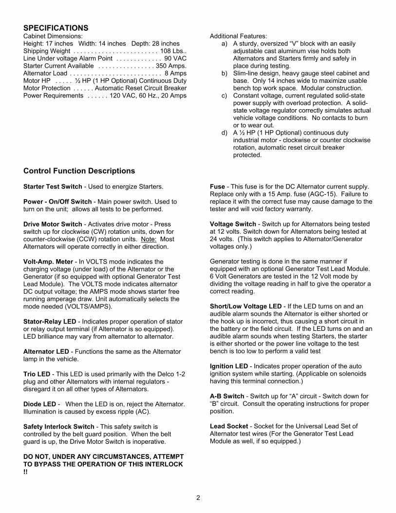
SPECIFICATIONSCabinet Dimensions:Height: 17 inches Width: 14 inches Depth: 28 inchesShipping Weight . . . . . . . . . . . . . . . . . . . . . . . . 108 Lbs..Line Under voltage Alarm Point . . . . . . . . . . . . . 90 VACStarter Current Available . . . . . . . . . . . . . . . . 350 Amps.Alternator Load . . . . . . . . . . . . . . . . . . . . . . . . . . 8 AmpsMotor HP . . . . . ½ HP (1 HP Optional) Continuous DutyMotor Protection . . . . . . Automatic Reset Circuit BreakerPower Requirements . . . . . . 120 VAC, 60 Hz., 20 Amps
Additional Features:a) A sturdy, oversized “V” block with an easily
adjustable cast aluminum vise holds bothAlternators and Starters firmly and safely inplace during testing.
b) Slim-line design, heavy gauge steel cabinet andbase. Only 14 inches wide to maximize usablebench top work space. Modular construction.
c) Constant voltage, current regulated solid-statepower supply with overload protection. A solid-state voltage regulator correctly simulates actualvehicle voltage conditions. No contacts to burnor to wear out.
d) A ½ HP (1 HP Optional) continuous dutyindustrial motor - clockwise or counter clockwiserotation, automatic reset circuit breakerprotected.
Control Function Descriptions
Starter Test Switch - Used to energize Starters.
Power - On/Off Switch - Main power switch. Used toturn on the unit; allows all tests to be performed.
Drive Motor Switch - Activates drive motor - Pressswitch up for clockwise (CW) rotation units, down forcounter-clockwise (CCW) rotation units. Note: MostAlternators will operate correctly in either direction.
Volt-Amp. Meter - In VOLTS mode indicates thecharging voltage (under load) of the Alternator or theGenerator (if so equipped with optional Generator TestLead Module). The VOLTS mode indicates alternatorDC output voltage; the AMPS mode shows starter freerunning amperage draw. Unit automatically selects themode needed (VOLTS/AMPS).
Stator-Relay LED - Indicates proper operation of statoror relay output terminal (if Alternator is so equipped). LED brilliance may vary from alternator to alternator.
Alternator LED - Functions the same as the Alternatorlamp in the vehicle.
Trio LED - This LED is used primarily with the Delco 1-2plug and other Alternators with internal regulators -disregard it on all other types of Alternators.
Diode LED - When the LED is on, reject the Alternator. Illumination is caused by excess ripple (AC).
Safety Interlock Switch - This safety switch iscontrolled by the belt guard position. When the beltguard is up, the Drive Motor Switch is inoperative.
DO NOT, UNDER ANY CIRCUMSTANCES, ATTEMPTTO BYPASS THE OPERATION OF THIS INTERLOCK!!
Fuse - This fuse is for the DC Alternator current supply. Replace only with a 15 Amp. fuse (AGC-15). Failure toreplace it with the correct fuse may cause damage to thetester and will void factory warranty.
Voltage Switch - Switch up for Alternators being testedat 12 volts. Switch down for Alternators being tested at24 volts. (This switch applies to Alternator/Generatorvoltages only.)
Generator testing is done in the same manner ifequipped with an optional Generator Test Lead Module. 6 Volt Generators are tested in the 12 Volt mode bydividing the voltage reading in half to give the operator acorrect reading.
Short/Low Voltage LED - If the LED turns on and anaudible alarm sounds the Alternator is either shorted orthe hook up is incorrect, thus causing a short circuit inthe battery or the field circuit. If the LED turns on and anaudible alarm sounds when testing Starters, the starteris either shorted or the power line voltage to the testbench is too low to perform a valid test
Ignition LED - Indicates proper operation of the autoignition system while starting. (Applicable on solenoidshaving this terminal connection.)
A-B Switch - Switch up for “A” circuit - Switch down for“B” circuit. Consult the operating instructions for properposition.
Lead Socket - Socket for the Universal Lead Set ofAlternator test wires (For the Generator Test LeadModule as well, if so equipped.)

3
ASSEMBLY INSTRUCTIONS
CAUTION: THE WEIGHT OF THE INDIVIDUAL COMPONENTS AND/OR THE ASSEMBLED UNIT MAY EXCEEDTHE SAFE LIMIT THAT MAY BE LIFTED BY ONE INDIVIDUAL. EXTREME CARE SHOULD BEEXERCISED WHEN HANDLING THIS MACHINE !
a) Attach the plastic handle to the outside of the upper belt guard with the self tapping screw.b) Thread the vise handle onto the vise.c) The upper guard interlock trip rod may need to be adjusted. Loosen the two (2) jam nuts on the interlock trip rod and
adjust the rod so that it trips the interlock switch just prior to the guard being in the DOWN position. Once theadjustment is made, tighten the jam nuts to secure the trip rod in place. To test the operation of the interlock, listencarefully as the guard is lowered. A faint "click" should be heard just before the guard is in the DOWN position,indicating that the trip rod has tripped the switch.
d) Plug the Universal Test Lead Set into the front panel. Read this manual completely before attempting to operate thismachine. This will insure years of trouble free operation and insure operator safety.
e) In the event of hidden shipping damage, contact the carrier immediately. Do not discard the packaging materials -save them for the carrier’s inspection.
INSTALLATION
a) Once you have the tester assembled, it is very important to install your machine in the following manner:b) The tester must be placed on a sturdy work bench or counter that is larger than the base of the tester.c) The tester must be plugged into a dedicated 120 VAC, 60 Hz., GROUNDED wall receptacle. It is suggested that the
supply wire to the outlet be no smaller than #12 AWG and be as close to the circuit breaker panel or fuse box aspossible. It is also suggested that if fuses are used, that the fuse be of a 20 Amp. slow blow type.
Use of an extension cord may degrade the performance of the tester and is not recommended. It may also causeserious internal heating in the machine.
d) For safety reasons and ease of operation, the tester should be placed on a sturdy work bench or counter top.
WARNING: This equipment, or the equipment that it is testing, may produce arcing or emitsparks. Locate this device a minimum of 18 inches above the floor.
Do not use outdoors or near flammable material.
This device employs rotating machinery. Do not operate it while wearing loose clothing orapparel that may become entangled, such as neckties.
OPERATION
WARNING: Attempting to test a generator without using the optional generator test module may cause damageto the internal electronics of this tester.
NOTE: The A/B switch must be properly positioned for alternators and generators. Normally alternators shouldbe tested with the switch in the "B" circuit.
Operating Procedures - Alternators:a) Mount the Alternator in the vise using the bar to secure the lower end to the vise. Secure the top portion of the
alternator with the hold down arm attached to the vise handle.b) Line up the motor and the Alternator pulleys by moving the vise to the left or to the right. Tighten the vise to the base
with the hold-down screws.c) Push the vise handle forward; attach the V-Belt and release the vise slowly.d) For Negative ground units, connect the large Black clamp (Ground) to the ground (GRD) terminal, or to the frame of
the Alternator being tested.e) For Negative ground units connect the small Red lead wire (Batt) to the terminal of the Alternator marked “BATT” or
“Output”.NOTE: On Positive ground units, the small Red lead and the large Black clamp are reversed.

4
f) Connect the small Green lead (FIELD) to the terminal marked "F", "FLD", or "FIELD" on alternators so equipped.g) Connect the small Yellow lead wire (Stator-Relay) to the terminal marked “STA” or “R” on Alternators so equipped. h) Set the program switches for 12 volt or 24 volt depending upon the output voltage of the device under test.I) Grasp the vice handle with one hand to steady the alternator and apply additional tension to the drive belt.
ALTERNATOR TEST SEQUENCE:
Test #1-If the SHORT/LOW VOLTAGE LED turns on and an audible alarm sounds, the alternator is either shorted or thehook-up is incorrect, thus causing a short circuit in the battery or the field circuit.
Check the hook-up. If it is correct, reject the alternator.
Test #2-Turn on the motor switch for the desired rotation direction. At this point, the unit is rotating with a load applied. Itshould start up quickly, If the motor stalls or a bearing noise is noticed, do not proceed. The Alternator under testhas mechanical problems and should be rejected.
Test #3-Observe the Volt-Meter.
- 12 Volt Alternators will indicate an operating voltage between 13.8 to 15.5 volts.
- 24 volt Alternators will indicate an operating voltage between 26.5 to 30.0 volts.
Test #4-Observe the Diode LED. This LED should not be lit. If the LED is on, the Alternator is defective.
Test #5-Observe the Stator/Relay LED - the LED should be on with Alternators having this feature and the Stator-Relay leadconnected.
Delcotrons and other internally regulated alternators using the 1-2 plug:
- The Diode Trio LED should be on when the alternator is electrically connected to the 1-2 plug, but is not rotating. Once the unit is under test and rotating, should the LED remain on, reject the alternator.
- On all other Alternators this LED will be off.
Chrysler Isolated Field Alternator:
- This type of Alternator has 2 insulated field terminals. To test this type of Alternator, ground one of the fieldterminals and connect the small Green (FLD) field lead (“FLD”) to the other terminal. Then proceed to test as aregular Alternator.
GENERATORS:
WARNING: Attempting to test a generator without using the optional Generator Test Module may causedamage to the internal electronics of this tester !
OPERATING PROCEDURES - STARTERS:a) Mount the Starter in the vise and secure it with the hold down clamp.b) Connect the large Black Negative (-Neg) battery clamp to a good ground connection on the Starter.c) Connect the large Red Positive (+Pos) battery clamp to the battery post of the solenoid or starter under test.d) On Solenoid equipped Starters, connect the short lead from the large Red battery clamp to the Solenoid Switch
Terminal (SW). If this lead is not used, be sure it is not contacting ground.e) On ignition terminal (R) equipped solenoids, connect the ignition clip (small Blue wire) to the terminal. The Ignition
LED should come on when this type of starter is being tested.

5
f) Hold the Starter Test Switch; the Starter should engage and spin up. Observe the meter reading. Check the no-load current draw against the published starter specifications. Do not over rev the Starter. Limit thetest to 2 seconds to allow time for the meter to stabilize and indicate the condition of the Starter. The meter shouldinitially read low and then ramp up to the current indicated in the specifications.
g) If the LOW VOLTAGE LED turns on and an audible alarm is detected, the starter is either shorted or the power linevoltage to the test bench is too low to perform a valid test.Should you suspect low supply voltage, have it checked by a qualified electrician. Use of an extension cord may alsocause the supply voltage to the test bench to be too low.
TYPICAL TEST SPECIFICATIONS:
ALTERNATORS:Output Voltage:12 Volt Alternators 13.8 to 15.5 Volts24 Volt Alternators 26.5 to 30.0 Volts
Tester LEDs: DIODE OffTRIO OffALT. OFF or on lowSTATOR* May Be ON
*Only if Yellow Clip or DN PlugConnected
Note: For some alternators, the TRIO or the ALT. LEDmay light when the alternator is connected, but notrotating.
OTHER ALTERNATOR SPECIFICATIONS:For other Alternator specifications, refer to the OEM orrebuilder's published specifications.
STARTERS:Delco Passenger with Solenoid:5 MT 70 to 100 Amps.10 MT 100 to 125 Amps.
Delco Passenger w/o Solenoid: 7 to 100 Amps.
Ford With Solenoid: 100 to 125 Amps.
Ford Without Solenoid: 60 to 90 Amps.
Chrysler Gear Reduction: 70 to 125 Amps.
Solenoids With Ignition Terminal (R): Ignition LEDshould be on.
Other Starter Specifications: For other starterspecifications, refer to the OEM or rebuilder's publishedspecifications.
MAINTENANCECAUTION: DO NOT ATTEMPT ANY MAINTENANCE BEFORE UNPLUGGING THE LINE PLUGFROM THE POWER RECEPTACLE!a) Extreme care should be taken not break any components or wire leads when doing any maintenance to the unit.b) Test leads can be cleaned and kept in a like new condition by cleaning them with petroleum jelly.c) The Test Bench has been designed for a long life of trouble free service and requires only the minimum amount of
maintenance to assure many years of dependable service. Good housekeeping techniques will insure dependability. The meter lens can be cleaned with a damp, clean rag utilizing a mild dish washing detergent/water solution. Thecase can be cleaned with a furniture grade spray wax.
d) The motor should be lubricated once a year with a few drops of light oil. Some testers may be supplied with sealed“Oilite” bushings and in this case, no lubrication is required.
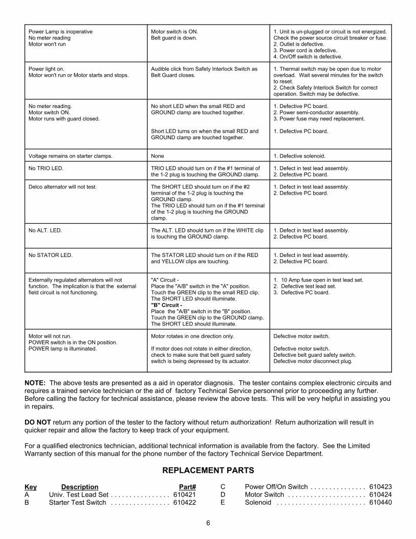
TROUBLESHOOTING GUIDEBEFORE YOU CALL FOR SERVICE, PROCEED WITH THE FOLLOWING TESTS. This tester is designed so that manyfunctional tests may be made without the need for additional test equipment. If a portion of the tester appears tomalfunction, proceed according to the following chart. For purposes of this guide, the Bench Tester may be divided intotwo sections:POWER PANEL SECTION - The left hand portion above the belt guard containing the On/Off Switches, etc.METER PANEL SECTION - The larger right hand portion containing the meter, A/B switch, etc.
WARNING: UNDER NO CIRCUMSTANCES SHOULD THE UNIT BE DISASSEMBLED WITH THE UNIT PLUG TOTHE WALL RECEPTACLE.
PROBLEM TEST POSSIBLE CAUSE
6
Power Lamp is inoperativeNo meter readingMotor won't run
Motor switch is ON.Belt guard is down.
1. Unit is un-plugged or circuit is not energized. Check the power source circuit breaker or fuse.2. Outlet is defective.3. Power cord is defective.4. On/Off switch is defective.
Power light on.Motor won't run or Motor starts and stops.
Audible click from Safety Interlock Switch asBelt Guard closes.
1. Thermal switch may be open due to motoroverload. Wait several minutes for the switchto reset.2. Check Safety Interlock Switch for correctoperation. Switch may be defective.
No meter reading.Motor switch ON.Motor runs with guard closed.
No short LED when the small RED andGROUND clamp are touched together.
Short LED turns on when the small RED andGROUND clamp are touched together.
1. Defective PC board.2. Power semi-conductor assembly.3. Power fuse may need replacement.
1. Defective PC board.
Voltage remains on starter clamps. None 1. Defective solenoid.
No TRIO LED. TRIO LED should turn on if the #1 terminal ofthe 1-2 plug is touching the GROUND clamp.
1. Defect in test lead assembly.2. Defective PC board.
Delco alternator will not test. The SHORT LED should turn on if the #2terminal of the 1-2 plug is touching theGROUND clamp.The TRIO LED should turn on if the #1 terminalof the 1-2 plug is touching the GROUNDclamp.
1. Defect in test lead assembly.2. Defective PC board.
No ALT. LED. The ALT. LED should turn on if the WHITE clipis touching the GROUND clamp.
1. Defect in test lead assembly.2. Defective PC board.
No STATOR LED. The STATOR LED should turn on if the REDand YELLOW clips are touching.
1. Defect in test lead assembly.2. Defective PC board.
Externally regulated alternators will notfunction. The implication is that the externalfield circuit is not functioning.
"A" Circuit -Place the "A/B" switch in the "A" position.Touch the GREEN clip to the small RED clip.The SHORT LED should illuminate."B" Circuit -Place the "A/B" switch in the "B" position.Touch the GREEN clip to the GROUND clamp.The SHORT LED should illuminate.
1. 10 Amp fuse open in test lead set. 2. Defective test lead set.3. Defective PC board.
Motor will not run.POWER switch is in the ON position.POWER lamp is illuminated.
Motor rotates in one direction only.
If motor does not rotate in either direction,check to make sure that belt guard safetyswitch is being depressed by its actuator.
Defective motor switch.
Defective motor switch.Defective belt guard safety switch.Defective motor disconnect plug.
NOTE: The above tests are presented as a aid in operator diagnosis. The tester contains complex electronic circuits andrequires a trained service technician or the aid of factory Technical Service personnel prior to proceeding any further. Before calling the factory for technical assistance, please review the above tests. This will be very helpful in assisting youin repairs.
DO NOT return any portion of the tester to the factory without return authorization! Return authorization will result inquicker repair and allow the factory to keep track of your equipment.
For a qualified electronics technician, additional technical information is available from the factory. See the LimitedWarranty section of this manual for the phone number of the factory Technical Service Department.
REPLACEMENT PARTS
Key Description Part#A Univ. Test Lead Set . . . . . . . . . . . . . . . . 610421B Starter Test Switch . . . . . . . . . . . . . . . . 610422
C Power Off/On Switch . . . . . . . . . . . . . . . 610423D Motor Switch . . . . . . . . . . . . . . . . . . . . . 610424E Solenoid . . . . . . . . . . . . . . . . . . . . . . . . 610440

7
F Power Semiconductor Assy.. . . . . . . . . 610442G Safety Interlock Switch . . . . . . . . . . . . . 610427H Front Panel Assy. . . . . . . . . . . . . . . . . . 610786I “V” Belt - 30" 1/2HP . . . . . . . . . . . . . . . 610455I "V" Belt - 34" 1HP . . . . . . . . . . . . . . . . . 610429J Fuse Holder . . . . . . . . . . . . . . . . . . . . . . 610430
Key Description Part#K "V" Pulley - 2.5" ½ HP . . . . . . . . . . . . . . 610454K "V" Pulley - 5" 1 HP . . . . . . . . . . . . . . . 610438L Vise Assembly . . . . . . . . . . . . . . . . . . . . 610436M Motor, ½ HP . . . . . . . . . . . . . . . . . . . . . 610435M Motor, 1 HP . . . . . . . . . . . . . . . . . . . . . . 610453N Swivel Pad w/ Rod . . . . . . . . . . . . . . . . 610441O Alternator Bracket . . . . . . . . . . . . . . . . . 610439* A. C. Cord . . . . . . . . . . . . . . . . . . . . . . . 605205* Power Light . . . . . . . . . . . . . . . . . . . . . . 610600* Front Panel Harness . . . . . . . . . . . . . . . 610778* Output Cables . . . . . . . . . . . . . . . . . . . . 610791* Transformer Assy. . . . . . . . . . . . . . . . . . 610941
8
LIMITED WARRANTYAssociated Equipment Corporation, 5043 Farlin, St. Louis, Missouri 63115, makes this limited warranty to the original and user purchaser of all Associatedproducts.
The Company hereby warrants the Purchaser that if the Product, or any parts thereof, shall prove to be defective due to improper workmanship or materials atany time up to and including NINETY (90) DAYS from the date of the Product’s purchase at retail, then the Company shall repair or replace the Product, orany part thereof, as the case may be, at the Company’s option, without charge to the Purchaser for parts and labor, provided that the Purchaser follows theprocedures set forth herein.
This warranty does not and shall not apply: (1) to any Product parts subject to normal wear and tear, including but not limited to, clamps, test lead sets, beltsand cables, (2) if the Product, or any part thereof, is subject to accident, misuse, abuse, or operated contrary to the company’s instructions pertaining to theProduct, or (3) to the Product, or any part thereof, damaged by alteration, or by improper repair or service not rendered by the Company.
TO OBTAIN WARRANTY REPAIR SERVICE:
1. Contact the Technical Service Department at the factory by either of the phone numbers listed below, or send in a request for service via FAX.
2. DO NOT SHIP THE UNIT, OR ANY OF ITS COMPONENT PARTS BACK WITHOUT PRIOR AUTHORIZATION !!
3. Be prepared to answer specific questions concerning what is or is not operating. Please have your instruction manual in front of you; please also havethe serial number and date of manufacture available (found on the rear of the cabinet).
4. A determination will then be made concerning repair.
If the Unit is in Warranty:
The part(s) will be invoiced and sent the next business day by ground service.The defective part(s) must be returned within thirty (30) days along with proof of warranty so that a credit will be issued offsetting the invoice for part andshipping charges.
If the Unit is NOT in Warranty:
The part(s) will be sent the next business day via a carrier of your choice. Parts and shipping charges will be billed net thirty (30) days to qualified wholesalers.
THIS IS THE ONLY EXPRESS LIMITED WARRANTY ASSOCIATED WITH THE PRODUCT AND THE COMPANY NEITHER ASSUMES NORAUTHORIZES ANYONE TO ASSUME OR MAKE ANY OTHER EXPRESS WARRANTY WITH RESPECT TO THE PRODUCT OTHER THAN THISEXPRESS LIMITED WARRANTY. ANY IMPLIED WARRANTY OF MERCHANTABILITY OR FITNESS FOR A PARTICULAR PURPOSE OF THISPRODUCT IS LIMITED TO A PERIOD OF NINETY (90) DAYS FROM THE DATE OF THE PRODUCT’S PURCHASE AT RETAIL BY THE PURCHASER. SOME STATES DO NOT ALLOW LIMITATIONS ON HOW LONG AN IMPLIED WARRANTY LASTS, SO THE ABOVE LIMITATION MAY NOT APPLY TOYOU.
The Company is not and shall not be responsible or otherwise liable for any loss, claim, injury or damage to any person or property, or lost profits or othersimilar loss damage, which may arise, directly or indirectly, result or be claimed to have resulted from a defect in the workmanship or material of the Productor any part thereof. Some states do not allow the exclusion or limitation of incidental or consequential damages, so the above limitation may not apply to you.
This warranty gives you specific legal rights, and you may also have other rights which vary from state to state.
Associated Equipment does not recognize, nor will it reimburse the user for any third party labor or material charges required to repair this piece of equipmentunless the user obtains written permission prior to having the work performed.
Should the user elect to return this device for repair without first contacting the factory and obtaining permission, the factory reserves the right to refusedelivery.
If you feel that you can service this unit yourself, you may elect to:
1. Remove the cover from the unit. Inspect for obvious damage, i.e., broken wires, burned or loose connections, etc.2. Have the unit near you when you call.3. Call 1-800-654-0853. In Missouri call 1-314-385-6541. A qualified service technician will ask you several questions and have you perform
several tests to determine the problem. FAX number 1-314-385-3254.
WARRANTY REGISTRATION:
1.. Check the Model/Serial Number printed on the back of this unit.2. Record the information below and keep this document for your permanent record.
MODEL/SERIAL # __________________________ PURCHASE DATE:________________
JOBBERS NAME: ___________________________________________________________
W2106 Rev.06/01 027-0609