Embed Size (px)
Citation preview
PROCEEDINGS OF SPIE
SPIEDigitalLibrary.org/conference-proceedings-of-spie
100W EUV light-source keycomponent technology update forHVM
Tsukasa Hori, Yasufumi Kawasuji, Hiroshi Tanaka, YukioWatanabe, Yutaka Shiraishi, et al.
Downloaded From: https://www.spiedigitallibrary.org/conference-proceedings-of-spie on 10/26/2017 Terms of Use: https://spiedigitallibrary.spie.org/ss/TermsOfUse.aspx
100W EUV light source key component technology update for HVMTsukasa Hori, Yasufumi Kawasuji, Hiroshi Tanaka, Yukio Watanabe, Yutaka Shiraishi, Tamotsu
Abe, Takeshi Okamoto, Takeshi Kodama, Hiroaki Nakarai, Taku Yamazaki, Shinji Okazaki,Takashi Saitou and Hakaru Mizoguchi
Gigaphoton Inc., 3-25-1 Shinomiya, Hiratsuka-shi, Kanagawa, 254-8555, Japan
ABSTRACT
Gigaphoton Inc. develops a high-power laser produced plasma extreme ultraviolet (LPP EUV) light source for high volume manufacturing which enables sub-10nm critical layer patterning for semiconductor device fabrication. Atechnology update of key components of a 100 W LPP-EUV light source is given in this paper. The key components efficiently produce a stable plasma and evacuate the tin debris from the EUV vessel with a magnetic debris mitigation system. The chosen technology guarantees therefore a high-power and long-life EUV light source system. Eachcomponent is described with updated data. The latest system performance results are also presented. They wereobtained from our proto LPP-EUV light systems which support 100 W output power
Keywords: EUV light source, EUV lithography, Laser Produced Plasma, Tin, CO2 laser, Droplet generator, Collector mirror, Debris mitigation, magnetic field
1. INTRODUCTIONLithography is one of the keys for semiconductor device manufacturing. A lithographic apparatus images a pattern onto a substrate via light illumination. Additional processes transform that pattern to an electrical circuit pattern. Every yearcircuit dimensions are getting smaller to enable advanced device production with higher integration. Hence, alithographic process is required to make smaller pattern with the progress of device specification. Optical resolution isgenerally given by the Rayleigh equation, Resolution = k1 lambda / NA. Where k1 is the k1factor, lambda is the lightsource wavelength and NA is the system numerical aperture. Thus there are three ways to improve the illuminatorresolution, namely, making a smaller circuit pattern. Many efforts have been done to improve those three factors for advanced devise production. ArF immersion lithography1) for high NA, >1, is a typical innovative breakthrough in orderto realize a smaller pattern feature dimension. The optical source for advanced lithography is expected to generate a shorter wavelength for higher resolution following Rayleigh’s equation. Excimer lasers, at present used for theconventional lithography process, generate deep ultraviolet light, with a wavelength of 248 nm for KrF laser and 193 nmby for ArF laser. A wavelength of ~10 nm, called extreme ultraviolet, EUV, was selected as next generation lithography light source. The resolution improves therefore tenfold compared with conventional lithography light sources. EUVsources need high energy excitation to be generated because of its large photon energy (90eV). Radiation from energetic electrons is a most typical EUV light generation method, synchrotron radiation (SR) is used as photon source for many applications needing strong light. Electron radiation based light generators can generate light with shorter wavelength from soft x-ray to hard x-ray in high power and intensity, but require huge utilities and can generate a wide wavelengthband. The EUV generation by a plasma from specific target material, on the other hand, can generate the desired wavelength region effectively. This type of EUV generator can generate EUV light inside a limited wavelength band depending on the material characteristics, and requires a smaller size, and less utility compared to the electron radiationtype. There are several plasma excitation methods for EUV generation. Major methods of plasma excitation are electricaldischarge, so-called discharge produced plasma, DPP2) and laser produced plasma, LPP. DPPs have been widely used aslight sources, for instance the mercury lamp for lithography, because of its reliability and simple structure.3) As a EUV light source, however, DPP is not suitable in some respects. The electrode structure is one issue to efficiently generate EUV light. For the discharge electrodes must be set at both sides of the plasma, and they limit the EUV collection efficiency from the isotropic EUV emission of the plasma. The electrode material selection is also an issue as EUV lightsource. High energy concentration is needed for EUV generation, which means that a large discharge current is needed,so the heat load to the electrode increases with increasing EUV power. Whereas DPP could solve these issues4), DPP hasdue to its generation principle limitations with respect to future power scalability. LPP, on the other hand, has no critical
Extreme Ultraviolet (EUV) Lithography VII, edited by Eric M. Panning, Kenneth A. Goldberg. Proc. ofSPIE Vol. 9776, 977625 · © 2016 SPIE · CCC code: 0277-786X/16/$18 · doi: 10.1117/12.2217947
Proc. of SPIE Vol. 9776 977625-1
Downloaded From: https://www.spiedigitallibrary.org/conference-proceedings-of-spie on 10/26/2017 Terms of Use: https://spiedigitallibrary.spie.org/ss/TermsOfUse.aspx
issues on its generation principle. The drive laser can concentrate its energy to a volume size with dimensions of its wavelength, which means that high energy excitation and small optical source size are possible. LPP also does not require any adjacent structure around the plasma, so the EUV emission from the plasma can be collected efficiently. Therefore, LPP is regarded as the next generation EUV light source for lithography, though LPP has some engineering issues to be solved.
Gigaphoton Inc. has been developing the EUV light source for semiconductor device manufacturing with LPP methods since 2002.5-9) EUV light, its wavelength is 13.5 nm, is generated from tin plasma which is produced from small tin liquid droplets supplied to the plasma point located in the middle of the light source vessel and energized (heated) by very high power carbon dioxide (CO2) laser irradiation. Engineering difficulties of LPP with tin are the realization of stable and efficient long-term operation. Tin fragment remain in the light source vessel after EUV emission and deposit on the EUV collector mirror surface resulting in power degradation due to EUV mirror reflectivity loss. A tin particle guiding system and hydrogen flow system, for example, can mitigate that reflectivity loss. Stable plasma generation with good drive laser shooting and tin droplet trajectory control can minimize the amount of large tin particles, and higher efficiency leads to minimal tin in the vessel contributing to stable and long-life operation.
Several lithography systems with LPP light source have already been set-up and are being operated in advanced factories10). At these sites trial production with 40 ~ 80 W is demonstrated. This status proofs that EUV lithography is promising to be the main stream for the next generation method supporting semiconductor manufacturing. But the EUV output power is still much smaller than the power requested for mass production. A EUV power of 250 W is necessary to realize reasonable cost for the production of logic and memory at the 7 nm node generation in coming years. Furthermore 500 W might be necessary in five years for high NA lithography for the 5 nm node generation. Therefore power scaling is a crucial issue for light source suppliers.
To cope with this situation, the Gigaphoton light source has unique and novel concepts for power scaling and stable operation. Firstly, the tin droplet size is highly optimized, i.e. minimum mass target for EUV generation, to achieve the appropriate balance of sufficient EUV power and minimum amount of tin debris. Secondly, the tin plasma is generated by dual shooting with different wavelength, which leads to very efficient EUV emission. At the same time, Gigaphoton’s original tin mitigation system, a magnetic field flux generated by super conducting magnets, guides tin which is highly ionized by efficient laser irradiation and traps the tin ions in ion catchers to not contaminate the surface of the collector mirror. As a result, the needed amount of hydrogen can be reduced, which means that the negative impact to shooting stability, e.g. shock wave inside the chamber, is very small and a stable high repetition rate can be achieved. In this paper performance of several key components is explained and outlined.
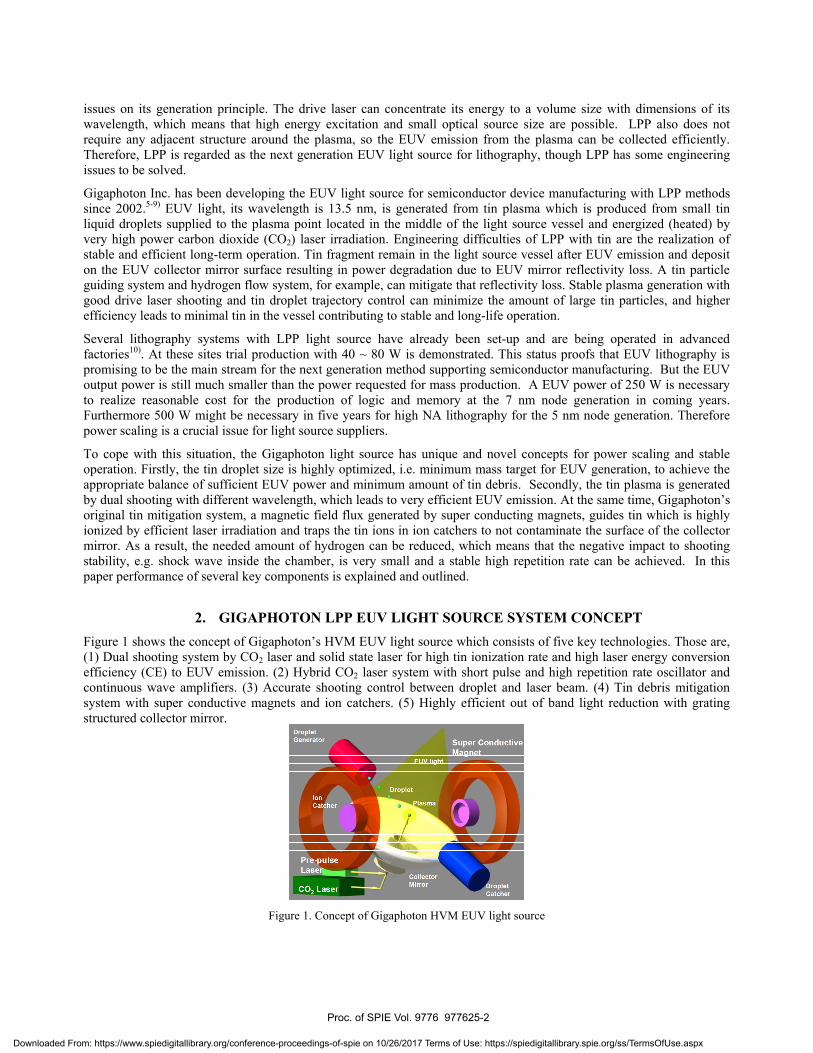
2. GIGAPHOTON LPP EUV LIGHT SOURCE SYSTEM CONCEPT Figure 1 shows the concept of Gigaphoton’s HVM EUV light source which consists of five key technologies. Those are, (1) Dual shooting system by CO2 laser and solid state laser for high tin ionization rate and high laser energy conversion efficiency (CE) to EUV emission. (2) Hybrid CO2 laser system with short pulse and high repetition rate oscillator and continuous wave amplifiers. (3) Accurate shooting control between droplet and laser beam. (4) Tin debris mitigation system with super conductive magnets and ion catchers. (5) Highly efficient out of band light reduction with grating structured collector mirror.
Figure 1. Concept of Gigaphoton HVM EUV light source
Proc. of SPIE Vol. 9776 977625-2
Downloaded From: https://www.spiedigitallibrary.org/conference-proceedings-of-spie on 10/26/2017 Terms of Use: https://spiedigitallibrary.spie.org/ss/TermsOfUse.aspx
Higher CE and PowerOptimum wavelength to transform droplets into fine mistHigher CE achievementwith ideal expansion of the finemist
Droplet(liquid)
pr
Fine -mist(liquid)
Ise
111110.droplet<20ym mist size <300ym
Long Life ChamberDebris mitigation by magnetic fieldIonized tin atoms are guided to tin catcher by magneticfield
Plasma Magnetic Field Ion Guiding(gas)
T%
,'T.
. ,
CO2 laser
100 %vaporizafion irradiation
to atom -100% ionization
a aNo Fragments Atom -0
Ions with low energytrapped by B field
Ion -0
Gas Etching
\L S
...
Remaining atoms tomirror etched by gas
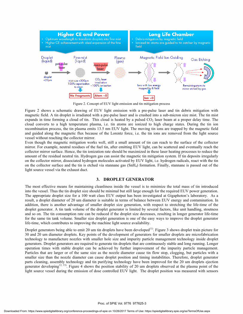
Figure 2. Concept of EUV light emission and tin mitigation process
Figure 2 shows a schematic drawing of EUV light emission with a pre-pulse laser and tin debris mitigation with magnetic field. A tin droplet is irradiated with a pre-pulse laser and is crushed into a sub-micron size mist. The tin mist expands in time forming a cloud of tin. This cloud is heated by a pulsed CO22 laser beam at a proper delay time. The cloud converts to a high temperature plasma, i.e. tin atoms are ionized to high charge states. During the tin ion recombination process, the tin plasma emits 13.5 nm EUV light. The moving tin ions are trapped by the magnetic field and guided along the magnetic flux because of the Lorentz force, i.e. the tin ions are removed from the light source vessel without reaching the collector mirror. Even though the magnetic mitigation works well, still a small amount of tin can reach to the surface of the collector mirror. For example, neutral residues of the fuel tin, after emitting EUV light, can be scattered and eventually reach the collector mirror surface. Hence, the tin ionization rate should be maximized in these laser heating processes to reduce the amount of the residual neutral tin. Hydrogen gas can assist the magnetic tin mitigation system. If tin deposits irregularly on the collector mirror, dissociated hydrogen molecules activated by EUV light, i.e. hydrogen radicals, react with the tin on the collector surface and the tin is etched via stannane gas (SnH4) formation. Finally, stannane is passed out of the light source vessel via the exhaust duct.
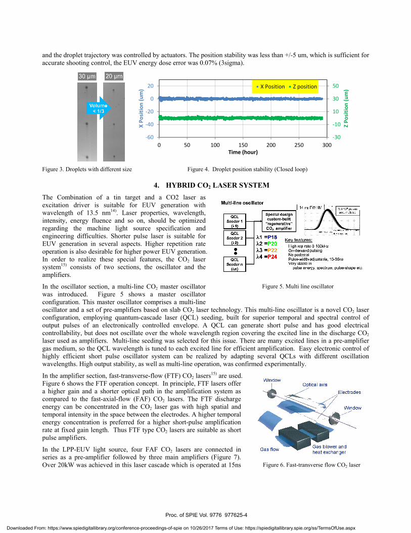
3. DROPLET GENERATOR The most effective means for maintaining cleanliness inside the vessel is to minimize the total mass of tin introduced into the vessel. Thus the tin droplet size should be minimal but still large enough for the required EUV power generation. The appropriate droplet size for a 100 watt class EUV output has been investigated at Gigaphoton’s laboratory. As a result, a droplet diameter of 20 um diameter is suitable in terms of balance between EUV energy and contamination. In addition, there is another advantage of smaller droplet size generation, with respect to stretching the life-time of the droplet generator. A tin tank volume of the droplet generator is limited by several factors, like unit handling, stoutness and so on. The tin consumption rate can be reduced if the droplet size decreases, resulting in longer generator life-time for the same tin tank volume. Smaller size droplet generation is one of the easy ways to improve the droplet generator life-time, which contributes to improving the machine light source availability.
Droplet generators being able to emit 20 um tin droplets have been developed11). Figure 3 shows droplet train picture for 30 and 20 um diameter droplets. Key points of the development of generators for smaller droplets are microfabrication technology to manufacture nozzles with smaller hole size and impurity particle management technology inside droplet generators. Droplet generators are required to generate tin droplets that are continuously stable and long running. Longer operation times with stable droplet can be achieved by further improvement of the impurity particle management. Particles that are larger or of the same size as the nozzle diameter cause tin flow stop, clogging, but particles with a smaller size than the nozzle diameter can cause droplet position and timing instabilities. Therefore, droplet generator parts cleaning, assembly technology and tin purifying technology have been improved for the 20 um droplets ejection generator developing12, 13). Figure 4 shows the position stability of 20 um droplets observed at the plasma point of the light source vessel during the emission of dose controlled EUV light. The droplet position was measured with sensors
Proc. of SPIE Vol. 9776 977625-3
Downloaded From: https://www.spiedigitallibrary.org/conference-proceedings-of-spie on 10/26/2017 Terms of Use: https://spiedigitallibrary.spie.org/ss/TermsOfUse.aspx
QCLSesderl
(^1)
QCLSeeder 2
(k2)
QCLSeeder n
(î.n)
Special designcustom -built"regenerative"CO2 amplifier
1 =P182=3=4 =ala
Liaccumulated
Key re:High rep-rate 0.100kHzOn- demand pulsingNo pedestalPulse - width- adjustable, 13 -35nsVery stable in
pulse energy, spectrum, pulse -shape etc.
30 pm 20pm
WindowOptical axis
Electrodes
Window
Figure 6. Fast-transverse flow CO2 laser
and the droplet trajectory was controlled by actuators. The position stability was less than +/-5 um, which is sufficient for accurate shooting control, the EUV energy dose error was 0.07% (3sigma).
-30
-10
10
30
50
-60
-40
-20
0
20
0 50 100 150 200 250 300
Z Po
sitio
n (u
m)
X Po
sitio
n (u
m)
Time (hour)
X Position Z position
Figure 3. Droplets with different size Figure 4. Droplet position stability (Closed loop)
4. HYBRID CO2 LASER SYSTEM The Combination of a tin target and a CO2 laser as excitation driver is suitable for EUV generation with wavelength of 13.5 nm14). Laser properties, wavelength, intensity, energy fluence and so on, should be optimized regarding the machine light source specification and engineering difficulties. Shorter pulse laser is suitable for EUV generation in several aspects. Higher repetition rate operation is also desirable for higher power EUV generation. In order to realize these special features, the CO2 laser system15) consists of two sections, the oscillator and the amplifiers.
In the oscillator section, a multi-line CO2 master oscillator was introduced. Figure 5 shows a master oscillator configuration. This master oscillator comprises a multi-line oscillator and a set of pre-amplifiers based on slab CO2 laser technology. This multi-line oscillator is a novel CO2 laser configuration, employing quantum-cascade laser (QCL) seeding, built for superior temporal and spectral control of output pulses of an electronically controlled envelope. A QCL can generate short pulse and has good electrical controllability, but does not oscillate over the whole wavelength region covering the excited line in the discharge CO2 laser used as amplifiers. Multi-line seeding was selected for this issue. There are many excited lines in a pre-amplifier gas medium, so the QCL wavelength is tuned to each excited line for efficient amplification. Easy electronic control of highly efficient short pulse oscillator system can be realized by adapting several QCLs with different oscillation wavelengths. High output stability, as well as multi-line operation, was confirmed experimentally.
In the amplifier section, fast-transverse-flow (FTF) CO2 lasers15) are used. Figure 6 shows the FTF operation concept. In principle, FTF lasers offer a higher gain and a shorter optical path in the amplification system as compared to the fast-axial-flow (FAF) CO2 lasers. The FTF discharge energy can be concentrated in the CO2 laser gas with high spatial and temporal intensity in the space between the electrodes. A higher temporal energy concentration is preferred for a higher short-pulse amplification rate at fixed gain length. Thus FTF type CO2 lasers are suitable as short pulse amplifiers.
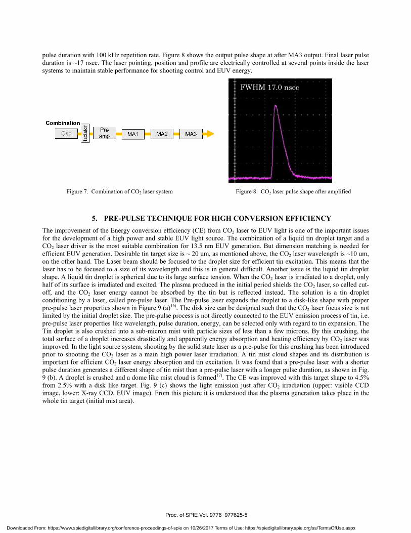
In the LPP-EUV light source, four FAF CO2 lasers are connected in series as a pre-amplifier followed by three main amplifiers (Figure 7). Over 20kW was achieved in this laser cascade which is operated at 15ns
Figure 5. Multi line oscillator
Proc. of SPIE Vol. 9776 977625-4
Downloaded From: https://www.spiedigitallibrary.org/conference-proceedings-of-spie on 10/26/2017 Terms of Use: https://spiedigitallibrary.spie.org/ss/TermsOfUse.aspx
Combination
Oscóroóo
Preamp MA1 MA2 MA3
F +F
LI- I r I . I- I r 1.
r...
:4i0-tievr-i,,y : ,+.E,;rt!f_r-r,+`i'.41
r-
1 - I r a.s.
. i r I ,ár %.l ^t
7 . rR
a ' L
9.
pulse duration with 100 kHz repetition rate. Figure 8 shows the output pulse shape at after MA3 output. Final laser pulse duration is ~17 nsec. The laser pointing, position and profile are electrically controlled at several points inside the laser systems to maintain stable performance for shooting control and EUV energy.
Figure 7. Combination of CO2 laser system Figure 8. CO2 laser pulse shape after amplified
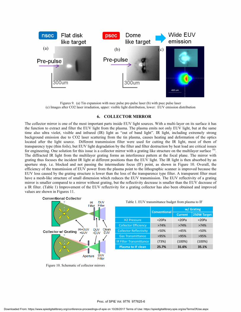
5. PRE-PULSE TECHNIQUE FOR HIGH CONVERSION EFFICIENCY The improvement of the Energy conversion efficiency (CE) from CO2 laser to EUV light is one of the important issues for the development of a high power and stable EUV light source. The combination of a liquid tin droplet target and a CO2 laser driver is the most suitable combination for 13.5 nm EUV generation. But dimension matching is needed for efficient EUV generation. Desirable tin target size is ~ 20 um, as mentioned above, the CO2 laser wavelength is ~10 um, on the other hand. The Laser beam should be focused to the droplet size for efficient tin excitation. This means that the laser has to be focused to a size of its wavelength and this is in general difficult. Another issue is the liquid tin droplet shape. A liquid tin droplet is spherical due to its large surface tension. When the CO2 laser is irradiated to a droplet, only half of its surface is irradiated and excited. The plasma produced in the initial period shields the CO2 laser, so called cut-off, and the CO2 laser energy cannot be absorbed by the tin but is reflected instead. The solution is a tin droplet conditioning by a laser, called pre-pulse laser. The Pre-pulse laser expands the droplet to a disk-like shape with proper pre-pulse laser properties shown in Figure 9 (a)16). The disk size can be designed such that the CO2 laser focus size is not limited by the initial droplet size. The pre-pulse process is not directly connected to the EUV emission process of tin, i.e. pre-pulse laser properties like wavelength, pulse duration, energy, can be selected only with regard to tin expansion. The Tin droplet is also crushed into a sub-micron mist with particle sizes of less than a few microns. By this crushing, the total surface of a droplet increases drastically and apparently energy absorption and heating efficiency by CO2 laser was improved. In the light source system, shooting by the solid state laser as a pre-pulse for this crushing has been introduced prior to shooting the CO2 laser as a main high power laser irradiation. A tin mist cloud shapes and its distribution is important for efficient CO2 laser energy absorption and tin excitation. It was found that a pre-pulse laser with a shorter pulse duration generates a different shape of tin mist than a pre-pulse laser with a longer pulse duration, as shown in Fig. 9 (b). A droplet is crushed and a dome like mist cloud is formed17). The CE was improved with this target shape to 4.5% from 2.5% with a disk like target. Fig. 9 (c) shows the light emission just after CO2 irradiation (upper: visible CCD image, lower: X-ray CCD, EUV image). From this picture it is understood that the plasma generation takes place in the whole tin target (initial mist area).
FWHM 17.0 nsec
Proc. of SPIE Vol. 9776 977625-5
Downloaded From: https://www.spiedigitallibrary.org/conference-proceedings-of-spie on 10/26/2017 Terms of Use: https://spiedigitallibrary.spie.org/ss/TermsOfUse.aspx
Flat disklike target
psec Dome * Wide EUVlike target emission
Conventional CollectorIR DUV
Filter Filter
IR +DUV DUV CleanCollectorw /Grating +EUV +EUV EUV
,o I, , ,Aperture DUV
Filter
Figures 9. (a) Tin expansion with nsec pulse pre-pulse laser (b) with psec pulse laser
(c) Images after CO2 laser irradiation, upper: visible light distribution, lower: EUV emission distribution
6. COLLECTOR MIRROR The collector mirror is one of the most important parts inside EUV light sources. With a multi-layer on its surface it has the function to extract and filter the EUV light from the plasma. The plasma emits not only EUV light, but at the same time also ultra violet, visible and infrared (IR) light as “out of band light”. IR light, including extremely strong background emission due to CO2 laser scattering from the tin plasma, causes heating and deformation of the optics located after the light source. Different transmission filter were used for cutting the IR light, most of them of transparency type (thin foils), but EUV light degradation by the filter and filter destruction by heat load are critical issues for engineering. One solution for this issue is a collector mirror with a grating like structure on the multilayer surface 18). The diffracted IR light from the multilayer grating forms an interference pattern at the focal plane. The mirror with grating thus focuses the incident IR light at different positions than the EUV light. The IR light is then absorbed by an aperture stop, i.e. blocked and not passing the intermediate focus (IF) point, as shown in Figure 10. Overall, the efficiency of the transmission of EUV power from the plasma point to the lithographic scanner is improved because the EUV loss caused by the grating structure is lower than the loss of the transparence type filter. A transparent filter must have a mesh-like structure of small dimension which reduces the EUV transmission. The EUV reflectivity of a grating mirror is smaller compared to a mirror without grating, but the reflectivity decrease is smaller than the EUV decrease of a IR filter. (Table 1) Improvement of the EUV reflectivity for a grating collector has also been obtained and improved values are shown in Figures 11.
Conventionalw/ Grating
Current 250W TargetH2 Pressure <20Pa <20Pa <20Pa
Collector Efficiency >74% >74% >74%Collector Reflectivity >50% >45% >50%Gas Transmittance >95% >95% >95%
IR Filter Transmittance (73%) (100%) (100%)Plasma to IF clean 25.7% 31.6% 35.1%
Figure 10. Schematic of collector mirrors
(a) (b) (c)
Table 1. EUV transmittance budget from plasma to IF
Proc. of SPIE Vol. 9776 977625-6
Downloaded From: https://www.spiedigitallibrary.org/conference-proceedings-of-spie on 10/26/2017 Terms of Use: https://spiedigitallibrary.spie.org/ss/TermsOfUse.aspx
Droplet generator Magnet
Magnet Plasma point
Ion catcher
Collector TLaser inlet
Dloplet catcher
Year
Pulse number
Debris in Centerof collector
(SEM x10,000)
Sn depositionrate
2014 2015
sta s clean with increasing pulse number
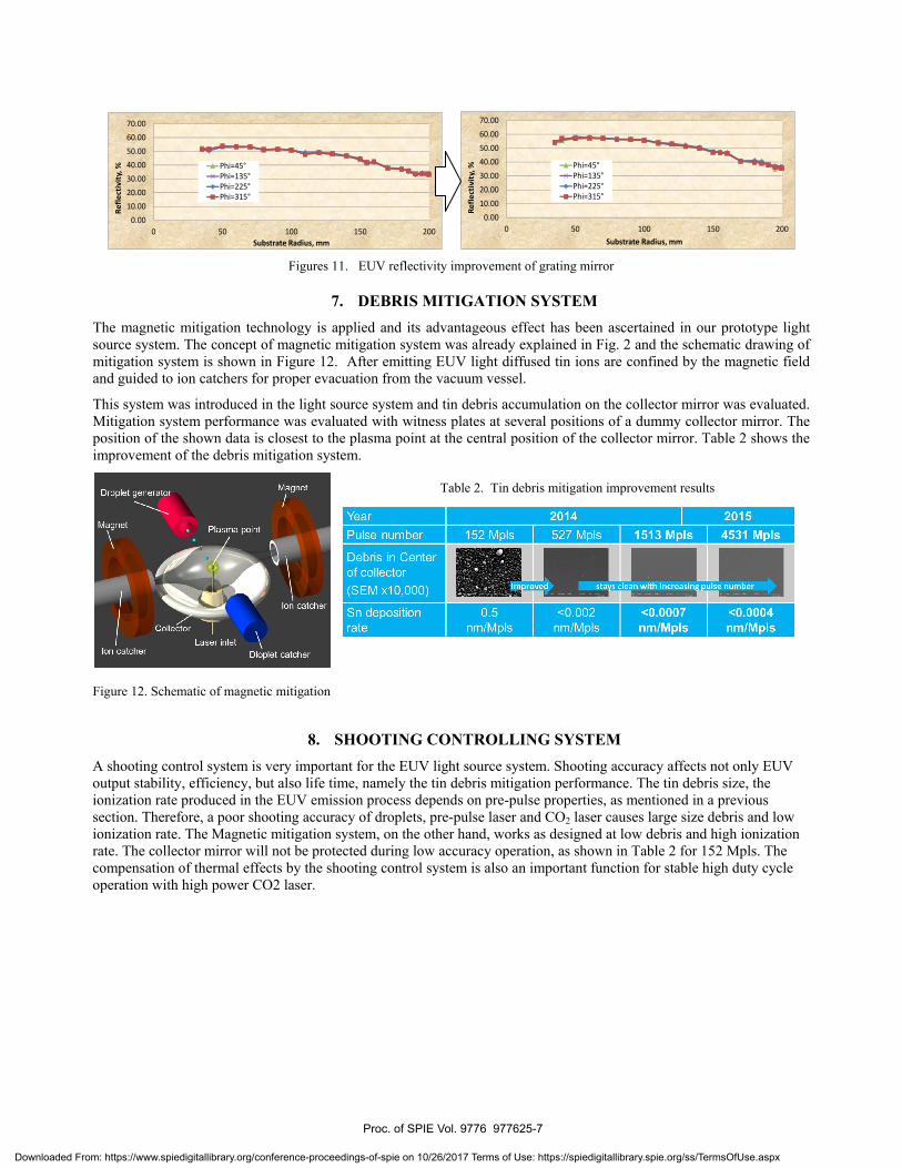
0.5nm/Mpls
<0.002 <0.0007 <0.0004nm/Mpls nm/Mpls nm/Mpls
0.0010.0020.0030.0040.0050.0060.0070.00
0 50 100 150 200
Refle
ctiv
ity, %
Substrate Radius, mm
Phi=45°Phi=135°Phi=225°Phi=315°
0.0010.0020.0030.0040.0050.0060.0070.00
0 50 100 150 200
Refle
ctiv
ity, %
Substrate Radius, mm
Phi=45°Phi=135°Phi=225°Phi=315°
Figures 11. EUV reflectivity improvement of grating mirror
7. DEBRIS MITIGATION SYSTEM The magnetic mitigation technology is applied and its advantageous effect has been ascertained in our prototype light source system. The concept of magnetic mitigation system was already explained in Fig. 2 and the schematic drawing of mitigation system is shown in Figure 12. After emitting EUV light diffused tin ions are confined by the magnetic field and guided to ion catchers for proper evacuation from the vacuum vessel.
This system was introduced in the light source system and tin debris accumulation on the collector mirror was evaluated. Mitigation system performance was evaluated with witness plates at several positions of a dummy collector mirror. The position of the shown data is closest to the plasma point at the central position of the collector mirror. Table 2 shows the improvement of the debris mitigation system.
Figure 12. Schematic of magnetic mitigation
8. SHOOTING CONTROLLING SYSTEM A shooting control system is very important for the EUV light source system. Shooting accuracy affects not only EUV output stability, efficiency, but also life time, namely the tin debris mitigation performance. The tin debris size, the ionization rate produced in the EUV emission process depends on pre-pulse properties, as mentioned in a previous section. Therefore, a poor shooting accuracy of droplets, pre-pulse laser and CO2 laser causes large size debris and low ionization rate. The Magnetic mitigation system, on the other hand, works as designed at low debris and high ionization rate. The collector mirror will not be protected during low accuracy operation, as shown in Table 2 for 152 Mpls. The compensation of thermal effects by the shooting control system is also an important function for stable high duty cycle operation with high power CO2 laser.
Table 2. Tin debris mitigation improvement results
Proc. of SPIE Vol. 9776 977625-7
Downloaded From: https://www.spiedigitallibrary.org/conference-proceedings-of-spie on 10/26/2017 Terms of Use: https://spiedigitallibrary.spie.org/ss/TermsOfUse.aspx
OSC PreAMP MA1 MA2 MA3
Pre-pulse laser
Isola
tor
Combinerunit
Droplet position sensor
Droplets timing sensor
EUV energy sensor
Droplet generator
Collector mirror
Beam controlof PPL and CO2
BeamTransferSystem
Droplet position control
Timing controlbetween dropletsand lasers
Dose controlLaser System
Focusunit
Coaxial laser beams
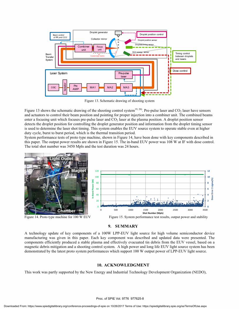
Figure 13. Schematic drawing of shooting system
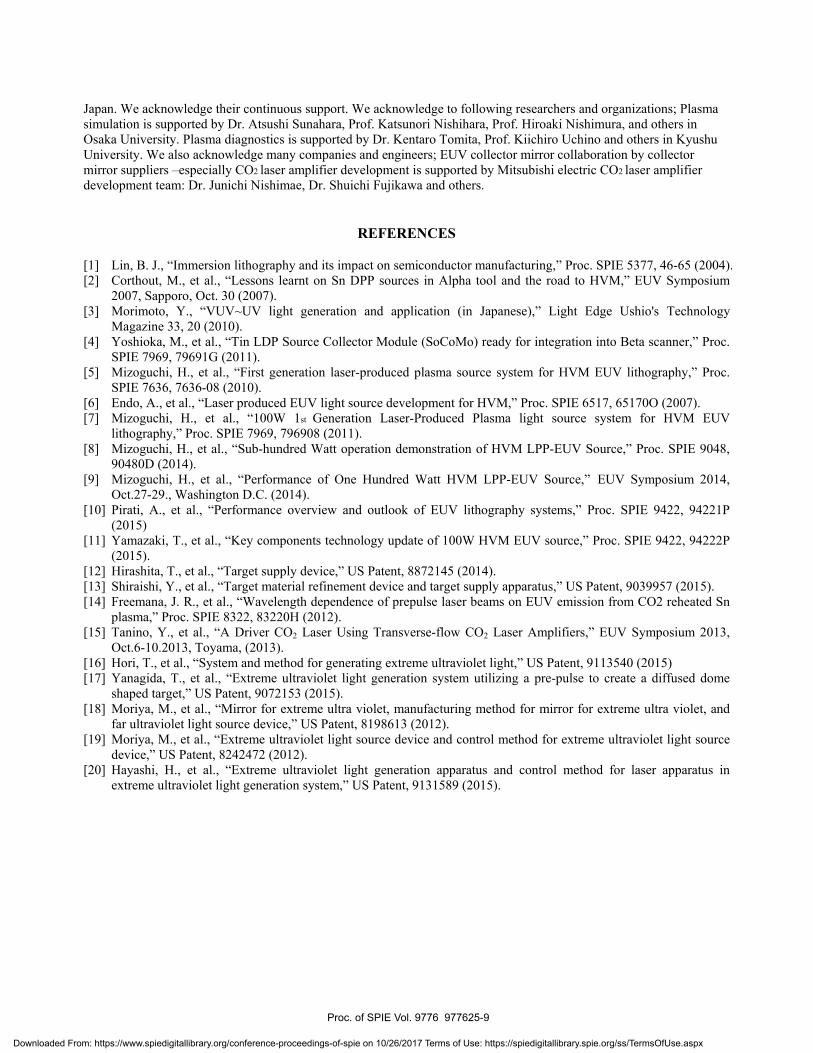
Figure 13 shows the schematic drawing of the shooting control system19, 20). Pre-pulse laser and CO2 laser have sensorsand actuators to control their beam position and pointing for proper injection into a combiner unit. The combined beamsenter a focusing unit which focuses pre-pulse laser and CO2 laser at the plasma position. A droplet position sensor detects the droplet position for controlling the droplet generator position and information from the droplet timing sensoris used to determine the laser shot timing. This system enables the EUV source system to operate stable even at higherduty cycle, burst to burst period, which is the thermal transition period.System performance tests of proto type machine, shown in Figure 14, have been done with key components described in this paper. The output power results are shown in Figure 15. The in-band EUV power was 108 W at IF with dose control.The total shot number was 3450 Mpls and the test duration was 24 hours.
0
2
4
6
8
10
12
0
20
40
60
80
100
120
0 500 1000 1500 2000 2500 3000 3500Do
se E
rror
3 si
gma(
%)
In B
and
Pow
er (W
)
Shot Number (Mpls)
Figure 14. Proto type machine for 100 W EUV Figure 15. System performance test results, output power and stability
9. SUMMARYA technology update of key components of a 100W LPP-EUV light source for high volume semiconductor devicemanufacturing was given in this paper. Each key component was described and updated data were presented. Thecomponents efficiently produced a stable plasma and effectively evacuated tin debris from the EUV vessel, based on amagnetic debris mitigation and a shooting control system. A high power and long life EUV light source system has been demonstrated by the latest proto system performances which support 100 W output power of LPP-EUV light source.
10. ACKNOWLEDGMENTThis work was partly supported by the New Energy and Industrial Technology Development Organization (NEDO),
Proc. of SPIE Vol. 9776 977625-8
Downloaded From: https://www.spiedigitallibrary.org/conference-proceedings-of-spie on 10/26/2017 Terms of Use: https://spiedigitallibrary.spie.org/ss/TermsOfUse.aspx
Japan. We acknowledge their continuous support. We acknowledge to following researchers and organizations; Plasma simulation is supported by Dr. Atsushi Sunahara, Prof. Katsunori Nishihara, Prof. Hiroaki Nishimura, and others in Osaka University. Plasma diagnostics is supported by Dr. Kentaro Tomita, Prof. Kiichiro Uchino and others in Kyushu University. We also acknowledge many companies and engineers; EUV collector mirror collaboration by collector mirror suppliers –especially CO2 laser amplifier development is supported by Mitsubishi electric CO2 laser amplifier development team: Dr. Junichi Nishimae, Dr. Shuichi Fujikawa and others.
REFERENCES
[1] Lin, B. J., “Immersion lithography and its impact on semiconductor manufacturing,” Proc. SPIE 5377, 46-65 (2004). [2] Corthout, M., et al., “Lessons learnt on Sn DPP sources in Alpha tool and the road to HVM,” EUV Symposium
2007, Sapporo, Oct. 30 (2007). [3] Morimoto, Y., “VUV~UV light generation and application (in Japanese),” Light Edge Ushio's Technology
Magazine 33, 20 (2010). [4] Yoshioka, M., et al., “Tin LDP Source Collector Module (SoCoMo) ready for integration into Beta scanner,” Proc.
SPIE 7969, 79691G (2011). [5] Mizoguchi, H., et al., “First generation laser-produced plasma source system for HVM EUV lithography,” Proc.
SPIE 7636, 7636-08 (2010). [6] Endo, A., et al., “Laser produced EUV light source development for HVM,” Proc. SPIE 6517, 65170O (2007). [7] Mizoguchi, H., et al., “100W 1st Generation Laser-Produced Plasma light source system for HVM EUV
lithography,” Proc. SPIE 7969, 796908 (2011). [8] Mizoguchi, H., et al., “Sub-hundred Watt operation demonstration of HVM LPP-EUV Source,” Proc. SPIE 9048,
90480D (2014). [9] Mizoguchi, H., et al., “Performance of One Hundred Watt HVM LPP-EUV Source,” EUV Symposium 2014,
Oct.27-29., Washington D.C. (2014). [10] Pirati, A., et al., “Performance overview and outlook of EUV lithography systems,” Proc. SPIE 9422, 94221P
(2015) [11] Yamazaki, T., et al., “Key components technology update of 100W HVM EUV source,” Proc. SPIE 9422, 94222P
(2015). [12] Hirashita, T., et al., “Target supply device,” US Patent, 8872145 (2014). [13] Shiraishi, Y., et al., “Target material refinement device and target supply apparatus,” US Patent, 9039957 (2015). [14] Freemana, J. R., et al., “Wavelength dependence of prepulse laser beams on EUV emission from CO2 reheated Sn
plasma,” Proc. SPIE 8322, 83220H (2012). [15] Tanino, Y., et al., “A Driver CO2 Laser Using Transverse-flow CO2 Laser Amplifiers,” EUV Symposium 2013,
Oct.6-10.2013, Toyama, (2013). [16] Hori, T., et al., “System and method for generating extreme ultraviolet light,” US Patent, 9113540 (2015) [17] Yanagida, T., et al., “Extreme ultraviolet light generation system utilizing a pre-pulse to create a diffused dome
shaped target,” US Patent, 9072153 (2015). [18] Moriya, M., et al., “Mirror for extreme ultra violet, manufacturing method for mirror for extreme ultra violet, and
far ultraviolet light source device,” US Patent, 8198613 (2012). [19] Moriya, M., et al., “Extreme ultraviolet light source device and control method for extreme ultraviolet light source
device,” US Patent, 8242472 (2012). [20] Hayashi, H., et al., “Extreme ultraviolet light generation apparatus and control method for laser apparatus in
extreme ultraviolet light generation system,” US Patent, 9131589 (2015).
Proc. of SPIE Vol. 9776 977625-9
Downloaded From: https://www.spiedigitallibrary.org/conference-proceedings-of-spie on 10/26/2017 Terms of Use: https://spiedigitallibrary.spie.org/ss/TermsOfUse.aspx