Embed Size (px)
Citation preview

PROCESS CONTROL INSTRUMENTATION
Product List Schedule
27101 Airport Road, Punta Gorda, FL 33982 Phone: 941-575-3800 Fax: 941-575-4085 800-333-6677 800-456-4085 www.pulsafeeder.com www. pulsatron.com
Effective 06/01/08
TABLE OF CONTENTS Important Information When Placing An Placing ................................................................................................................................................. 3 Process Control Instrumentation Vision Series One Step Model ....................................................................................................................................... 4-6 Vision Series Model UV and LV ....................................................................................................................................... 6 IntelliSense / Sensor Package .......................................................................................................................................... 7 Replacement Sensors ...................................................................................................................................................... 7 Flow Assembly .................................................................................................................................................................. 8 Relay Expansion Box ....................................................................................................................................................... 8 USB Expansion Hub ......................................................................................................................................................... 9 IntelliScan ......................................................................................................................................................................... 9 IntelliSense ..................................................................................................................................................................... 10 Accessories/ Parts .......................................................................................................................................................... 10 Custom Panel Systems .................................................................................................................................................. 11 Cooling Tower Controllers PULSAtrol MC9000 Series Controllers ..................................................................................................................... 12-14 MC9000 Series Panel Systems ...................................................................................................................................... 15 MC9000 Series Sensors & MC9500 Series Accessories ............................................................................................... 16 MCT 100 Series pH/ORP controllers .............................................................................................................................. 16 MicroVision Series Controller……………………………...…………………………………………………………………….17 Microtrac Series Controller ............................................................................................................................................. 18 DCS 900 Series Controller ............................................................................................................................................. 19 ACT Series Controller ..................................................................................................................................................... 19 CTS Panel Systems ....................................................................................................................................................... 20 Boiler Controllers PULSAtrol MB9000 Series Controllers ...................................................................................................................... 21-23 MB9000 Series Panel Systems ...................................................................................................................................... 24 MB9000 Series Sensors & MB9600 Series Accessories ............................................................................................... 25 MBC100 Series Controller .............................................................................................................................................. 25 ABC Series Controller & Parts ........................................................................................................................................ 25 Cables…….. .............................................................................................................................................................. 26-27 Prefabricated Systems ................................................................................................................................................... 28 Timers MicroVision Series Timer…………………………………………………………………………………………………………29 PULSAtrol MPT Series Timers ....................................................................................................................................... 30 Analog Timers ................................................................................................................................................................. 31 Accessories Digital Glycol Feeders .................................................................................................................................................... 32 Flow Controllers .............................................................................................................................................................. 33 Corrosion Coupon Racks & Deposit Monitors ........................................................................................................... 33-34 Corporation Stops, Surge Protector and Sample Coolers ............................................................................................. 33 Contacting Head Water Meters ...................................................................................................................................... 35 Valves - Cooling Towers ................................................................................................................................................. 36 Valves - Boilers & Sample Coolers ............................................................................................................................ 37-38 Portable Testers for Conductivity and Calibration Solutions .......................................................................................... 39 Parts ACT/ABC ........................................................................................................................................................................ 40 PULSAtrol .................................................................................................................................................................. 41-44 Policies and Procedures ......................................................................................................................................... 45-46 Terms and Conditions………………………………………………………………………………………………………….47
DUE TO CONTINUOUS IMPROVEMENT OF OUR PRODUCTS, WE RESERVE THE RIGHT TO UPDATE THE INFORMATION CONTAINED IN THIS CATALOG WITHOUT NOTICE.
3
IMPORTANT INFORMATION WHEN PLACING AN ORDER 1) Fax, mail or telephone orders directly to the Customer Service Department:
Pulsafeeder Incorporated—A Unit of IDEX Corporation Standard Product Operations Main Office & Manufacturing Facility
27101 Airport Road, Punta Gorda, Florida, USA 33982-2462 E-Mail: [email protected] Telephone: 800-333-6677 or 941-575-3800 Fax: 800-456-4085 or 941-575-4085
www.pulsatron.com
2) Please have the following information available when placing an order:
Account Name Special Tags or Marks (if needed) Billing Zip Code Item(s) Being Ordered Purchase Order Number Quantity of Each Item Ship To Address
3) Orders are immediately entered into the computer upon receipt. Our ability to change in house orders is limited. Please be certain your orders are complete when placed.
4) For assistance or to order a “special” pump model not available in the price schedule, please contact our Technical
Support Department. 5) Orders are assigned standard lead times based on the size of the order and the time required to manufacture the
particular products. Requests to expedite orders may be routed through our Customer Service Department. 6) Repairs and returns are coordinated through our Customer Service Department. All orders returned must have
factory authorization and are subject to a 25% restocking charge. 7) Other Locations:
PULSAFEEDER (Knight UK Limited) 15 Brunel Centre Newton Road Crawley, West Sussex, England, RH10 9YU Tel: +44 80022102210 Fax: +44 80044104410 Latin America (Office Only) Hegel 153-602, Colonia Polanco, 11560 Mexico, D.F., Mexico Tel: 52-555-255-1357 Fax: 52-555-255-1356
Far East (Office Only) Room 3403, South Tower, Hong Kong Plaza No 283 Huai Hai Zhong Road Shanghai 200021, China Tel: 86-2163906367 Fax: 86-2163863338 IDEX India Private Ltd. 202 Matharu Arcade 32, Subhash Road, Vile Parie (East), Mumbai-400 057, India Tel: 91-22-66976631 Fax: 91-22-66976633
• Prices are subject to change without notice and are effective when order is accepted and acknowledged at point of shipment.
• When ordering, specify your P.O. number, model number, quantity, price, shipping and/or billing address and order date.
• Standard terms are NET 30 days from date of invoice for approved accounts on open account. • WE ACCEPT VISA AND MASTERCARD. • ONE PERCENT DISCOUNT AVAILABLE FOR PAYMENT WITHIN 10 DAYS OF INVOICE DATE FOR AC-
COUNTS THAT ARE CURRENT. • PAYMENT BY CREDIT CARD WILL NOT RECEIVE AN ADDITIONAL DISCOUNT. • All prices are F.O.B. Punta Gorda, FL or factory warehouse location. • Custom product sales are final. • Charges for export documentation apply. • Expediting fees may apply. • Fees for changes to or cancellation of orders may apply. • Minimum factory order of $50. • Possession of price schedule does not guarantee right to purchase direct from factory.
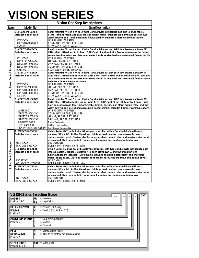
VISION SERIES The Vision Series line of process control instrumentation has been designed to handle a multitude of applications and is modular and expandable. The innovative use of USB technology makes these units customizable. Soft keys allow for easy programming and flexibility. In a few simple steps, you can create a custom control package for your application: 1) Start by selecting a UV or LV controller from the guide (page 6). 2) Select the desired IntelliSense packages (page 7). 3) If ordering an LV unit and more than three USB inputs/outputs are required, select a USB Hub (page 9). 4) If ordering an LV unit and more than four relays are required, select a Relay Expansion Box (page 8). 5) Choose a flow assembly with or without a panel mount (page 8) or a custom panel system (page 11). 6) Accessorize! Make your calibration high tech. . .check out the IntelliScan handheld on page 9.
Model UV The Vision Series Model UV is a single system process control instrument. Included as standard are two IntelliSense connections allowing for the use of one Multipurpose IntelliSense input/output and one general sensor IntelliSense in-put (conductivity, pH or ORP); four selectable relays; one alarm relay; three taggable timers; one flow switch input; and one input suitable for use with dry contact or hall effect water meters.
Model LV
The Vision Series Model LV is a dual system process control instrument. As standard, it comes with three IntelliSense connections (allowing for the use of three general sensor inputs, two general sensor inputs and one multipurpose input/output or one general sensor input and two multipurpose inputs/outputs), four selectable relays, one alarm relay, six taggable timers, two flow switch inputs, and two inputs suitable for use with dry contact or hall effect water meters. The LV's capability can be maximized to allow it to handle up to two Multipurpose IntelliSense inputs/outputs and any combination of up to four conductivity, pH or ORP (general sensors) IntelliSense inputs through the use of a USB Hub (page 8) and up to eight selectable relays through the use of a Relay Expansion Box (page 6). Note: Ion specific probes require the use of a multipurpose IntelliSense. When using an ion specific probe, the pack-age counts as both a general sensor IntelliSense input and a multipurpose IntelliSense input.
Model Number
Con
duct
ivity
pH c
ontr
ol
OR
P co
ntro
l
Inhi
bito
r
Bio
cide
s
Prog
ram
mab
le
timer
s
Wat
er M
eter
Inpu
t
Flow
Sw
itch
Pane
l Mou
nted
Ethe
rnet
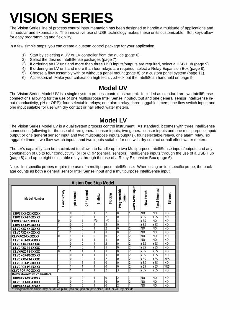
CUVCXXX-XX-XXXXX 1 0 0 1 2 0 1 NO NO NO CUVCXXX-F1-XXXXX 1 0 0 1 2 0 1 YES YES NOCUVXXOX-F1-XXXXX 0 0 1 **0 **0 3 1 YES NO NO CUVCXXX-P1-XXXXX 1 0 0 1 2 0 1 YES YES NO CLVCXXX-XX-XXXXX 1 0 0 1 2 0 2 NO NO NO CLVCPXX-XX-XXXXX 1 1 0 1 1 0 2 NO NO NOCLVXPOX-XX-XXXXX 0 1 1 0 0 2 2 NO NO NO CLVCXOX-XX-XXXXX 1 0 1 1 1 0 2 NO NO NO CLVCXXX-P1-XXXXX 1 0 0 1 2 0 2 YES YES NO CLVCPXX-P2-XXXXX 1 1 0 1 1 0 2 YES YES NO CLVXPOX-P2-XXXXX 0 1 1 1 1 0 2 YES YES NO CLVCXOX-P2-XXXXX 1 0 1 1 1 0 2 YES YES NO CLVCXXX-P1-EXXXX 1 0 0 1 2 0 2 YES YES YES CLVCPOX-P3-XXXXX 1 1 1 1 0 0 2 YES YES NO CLVCPOX-P3-EXXXX 1 1 1 1 0 0 2 YES YES YESCLVCPOR-PC-XXXXX 1 1 1 1 2 3 2 YES YES NO
BUVBXXX-XX-XXXXX 1 0 0 1 0 2 1 NO NO NO BLVBBXX-XX-XXXXX 2 0 0 2 0 0 2 NO NO NO BUVBXXX-XX-XPXXX 1 0 0 1 0 2 1 NO NO NO** Programmable timers may be set as pulse, percent, percent post bleed, limit, or 28 Day biocide.
Vision One Step Model
Boiler Blowdown controllers

5
Item Model No. Item DescriptionCUVCXXX-XX-XXXXX Vision Series UV with Conductivity Intellisense package (15’ USB cable). Bleed , inhibitorIncludes one of each: feed, and dual biocides output relays. Includes an alarm output relay, and water meter
inputs as standard. UVP1SXXX UV, PREWIRE, NO PANEL ISPCSTD-U015-XXX COND. HAT, PROBE, 15 FT. USBCUVCXXX-F1-XXXXX Vision Series UV with Conductivity Intellisense package (3’ USB cable). Bleed, inhibitorIncludes one of each: feed, and dual biocide output relays. Includes an alarm output relay, and water meter input,
and flow assembly. UVP1SXXX UV, PREWIRE ISPCSTD-U003-XXX COND. HAT, PROBE, 3 FT. USB FA1T-XL FLOW ASS'Y, 1-TEE, NO PANELCUVXXOX-F1-XXXXX Vision Series UV with an ORP Intellisense package (3’ USB cable). ORP Control, and threeIncludes one of each: programmable timer output relays. Includes an alarm output relay, and water meter input,
and flow assembly. UVP1SXXX UV, PREWIRE ISPOSTD-U003-XXX ORP. HAT, PROBE, 3 FT. USB FA1T-XL FLOW ASS'Y, 1-TEE, NO PANELCUVCXXX-P1-XXXXX Panel Mounted Vision Series UV with Conductivity Intellisense package (3’ USB cable).Includes one of each: Bleed, inhibitor feed, and dual biocide output relays. Includes an alarm output relay, and
water meter input, and a mounted flow assembly UVP1PXXX UV , PREWIRE, W/PANEL ISPCSTD-P003-XXX COND. HAT, PROBE, 3 FT. USB FA1T-PL FLOW ASS'Y, 1-TEE, W/PANELCLVCXXX-XX-XXXXX Vision Series LV with Conductivity Intellisense package (15’ USB cable). Bleed , inhibitorIncludes one of each: feed, and dual biocide output relays. Includes an alarm output relay, and two water meter
inputs as standard. LVP1SXXX LV, PREWIRE, NO PANEL ISPCSTD-U015-XXX COND. HAT, PROBE, 15 FT. USBCLVCPXX-XX-XXXXX Vision Series LV with Conductivity and pH Intellisense package (15’ USB cable). Bleed, pHIncludes one of each: Acid feed, inhibitor feed, and single biocide output relays. Includes an alarm output relay,
and two water meter inputs as standard. LVP1SXXX LV, PREWIRE, NO PANEL ISPCSTD-U015-XXX COND. HAT, PROBE, 15 FT. USB ISPPSTD-U015-XXX pH HAT, PROBE, 15 FT. USBCLVXPOX-XX-XXXXX Vision Series LV with pH and ORP Intellisense packages (15’ USB cable). pH Acid feed, ORPIncludes one of each: Control, and two programmable timer output relays. Includes an alarm output relay, and two
water meter inputs. LVP1SXXX LV, PREWIRE, NO PANEL ISPPSTD-U015-XXX pH HAT, PROBE, 15 FT. USB ISPOSTD-U015-XXX ORP HAT, PROBE, 15 FT. USBCLVCXOX-XX-XXXXX Vision Series LV with Conductivity and ORP Intellisense packages (15’ USB cable). Bleed,Includes one of each: ORP Control, inhibitor feed, and single biocide output relays. Includes an alarm output
relay, and two water meter inputs as standard. LVP1SXXX LV, PREWIRE, NO PANEL ISPCSTD-U015-XXX COND. HAT, PROBE, 15 FT. USB ISPOSTD-U015-XXX ORP HAT, PROBE, 15 FT. USBCLVCXXX-P1-XXXXX Panel mounted Vision Series LV with Conductivity Intellisense package (3’ USB cable).Includes one of each: Bleed, inhibitor feed, and dual biocide output relays. Includes an alarm output relay, and
two water meter inputs as standard and a mounted flow assembly. LVP1PXXX LV PREWIRE, W/PANEL ISPCSTD-P003-XXX COND. HAT, PROBE, 3 FT. USB FA1T-PL FLOW ASS'Y, 1-TEE, W/PANELCLVCPXX-P2-XXXXX Panel mounted Vision Series LV with Conductivity and pH Intellisense packages (3’ USBIncludes one of each: cable). Bleed, pH Acid Feed, inhibitor feed, and single biocide output relays. Includes an
alarm output relay, and two water meter inputs as standard and a mounted flow assembly. LVP1PXXX LV, PREWIRE, W/PANEL ISPCSTD-P003-XXX COND. HAT, PROBE, 3 FT. USB ISPPSTD-P003-XXX pH HAT, PROBE, 3 FT. USB FA2T-PL FLOW ASS'Y, 2-TEE, W/PANELCLVXPOX-P2-XXXXX Panel mounted Vision Series LV with pH and ORP Intellisense packages (3’ USB cable).Includes one of each: pH Acid Feed, ORP Control, inhibitor feed, and two programmable timer output relays.
Includes an alarm output relay, and two water meter inputs as standard and a mountedflow assembly.
LVP1PXXX LV, PREWIRE, W/PANEL ISPPSTD-P003-XXX pH HAT, PROBE, 3 FT. USB ISPOSTD-P003-XXX ORP HAT, PROBE, 3 FT. USB FA2T-PL FLOW ASS'Y, 2-TEE, W/PANELCLVCXOX-P2-XXXXX Panel mounted Vision Series LV with Conductivity and ORP Intellisense packages (3’ USBIncludes one of each: cable). Bleed, ORP Control, inhibitor feed, and single biocide output relays. Includes an
alarm output relay, and two water meter inputs as standard and a mounted flow assembly. LVP1PXXX LV, PREWIRE, W/PANEL ISPOSTD-P003-XXX ORP HAT, PROBE, 3FT. USB ISPCSTD-P003-XXX COND. HAT, PROBE, 3 FT. USB FA2T-PL FLOW ASS'Y, 2-TEE, W/PANEL
Vision One Step DescriptionsC
oolin
g To
wer
Con
trol
Pac
ages
VISION SERIES
VISION SERIES Item Model No. Item Description
CLVCXXX-P1-EXXXX Panel Mounted Vision Series LV with Conductivity Intellisense package (3’ USB cable).Includes one of each Bleed, inhibitor feed, and dual biocide output relays. Includes an alarm output relay, two
water meter inputs, and a mounted flow assembly. Includes Ethernet communications LVP3PXXX LV, PREWIRE, W/PANEL ISPCSTD-P003-XXX COND. HAT, PROBE, 3 FT. USB FA1T-PL FLOW ASS'Y, 2-TEE, W/PANELCLVCPOX-P3-XXXXX Panel mounted Vision Series LV with Conductivity, pH and ORP Intellisense packages (3’Includes one of each: USB cable). Bleed, pH Acid Feed, ORP Control and inhibitor feed output relays. Includes
an alarm output relay, and two water meter inputs as standard and a mounted flow assembly. LVP1PXXX LV, PREWIRE, W/PANEL ISPPSTD-P003-XXX pH HAT, PROBE, 3 FT. USB ISPOSTD-P003-XXX ORP HAT, PROBE, 3 FT. USB ISPCSTD-P003-XXX COND. HAT, PROBE, 3 FT. USB FA3T-PL FLOW ASS'Y, 3-TEE, W/PANELCLVCPOX-P3-EXXXX Panel mounted Vision Series LV with Conductivity, pH and ORP Intellisense packages (3’Includes one of each: USB cable). Bleed output relay, pH Acid Feed, ORP Control and an inhibitor feed. Includes
an alarm output relay, and two water meter inputs as standard and a mounted flow assembly.Includes Ethernet communications.
LVP3PXXX LV, PREWIRE, W/PANEL ISPPSTD-P003-XXX pH HAT, PROBE, 3 FT. USB ISPOSTD-P003-XXX ORP HAT, PROBE, 3 FT. USB ISPCSTD-P003-XXX COND. HAT, PROBE, 3 FT. USB FA3T-PL FLOW ASS'Y, 3-TEE, W/PANELCLVCPOS-PC-EXXXX Panel mounted Vision Series LV with Conductivity, pH and ORP Intellisense packages (3’Includes one of each: USB cable). Bleed output relay, pH Acid Feed, ORP Control, an inhibitor feed timer, dual
biocide program and three programmable timers. Includes an alarm output relay, and twowater meter inputs as std and a mounted flow assembly. Includes Ethernet communications.
LVP3PXXX LV, PREWIRE, W/PANELISPCSTD-P003-XXX COND. HAT, PROBE, 3 FT. USBISPPSTD-P003-XXX pH HAT, PROBE, 3 FT. USBISPOSTD-P003-XXX ORP HAT, PROBE, 3 FT. USBRB-PU003P-XXX Relay Expansion boxUH115-03P-XXX USB expansion hubPMS-PE3XXX-COXX-XXX11 Panel mount assembly
BUVBXXX-XX-XXXXX Vision Series UV Single boiler Blowdown controller, with a Conductivity IntellisenseIncludes one of each: package (50’ cable). Boiler Blowdown, inhibitor feed, and two programmable timer
outputs are included. System also Includes an alarm output relay, and a water meter inputas standard. Unit has conduit connections for wiring the input and output power.
UVC1SXXX UV, CONDUIT ISPCCBS-E050-XXX BOILER HAT, PROBE, 50 FT. cableBLVBBXX-XX-XXXXX Vision Series LV Dual boiler blowdown controller, with two Conductivity Intellisense pkgsIncludes one of each: (two 50’ cables). Boiler Blowdown 1, Boiler Blowdown 2, and two inhibitor feed
timer outputs are included. System also Includes an alarm output relay, and two watermeter inputs as std. Unit has conduit connections for wiring the input and output power.
LVC1SXXX LV, CONDUIT (2) ISPCCBS-E050-XXX BOILER HAT, PROBE, 50 FT. cableBUVBXXX-XX-XPXXX Vision Series UV Single boiler Blowdown controller, with a Conductivity IntellisenseIncludes one of each: package (50’ cable). Boiler Blowdown, inhibitor feed, and two programmable timer
outputs are included. System also Includes an alarm output relay, and a water meter inputas standard. Unit has conduit connections for wiring the input and output power.
UVC1SXXX UV, CONDUIT ISPCCBS-E050-XXX BOILER HAT, PROBE, 50 FT. cable
Vision One Step Descriptions
Boi
ler
Con
trol
Pac
kage
sC
oolin
g To
wer
Con
trol
Pac
kage
s
_ _ _ _ _ XXXMODELS UV = UniVisionPosition 1 & 2 LV = LiquiVision
RELAY & POWER P = Prewire (115V only)WIRING C = Conduit (required for CE) Position 3
COMMUNICATIONS 1 = No CommunicationsPosition 4 2 = Modem
3 = Ethernet
PANEL S = Standard (No Panel)DESIGNATOR P = Unit to be factory mounted on panelPosition 5
SUFFIX CODE XXX = Suffix CodePosition 6, 7 & 8
VISION Series Selection Guide

7
VISION SERIES IntelliSense/Sensor Package
By converting an analog sensor input to a digital signal, the IntelliSense provides auto sensor recognition, eliminates drifting potential and allows travel of up to 150 feet (multipurpose IntelliSense has a max of 15'). Each of the 5 avail-able sensory heads are color coded and measure a multitude of variables. Because the Vision Series is completely modular, the controller discount will be applied when purchasing an IntelliSense/Sensor Package. NOTE: The multipurpose IntelliSense can only be used with a USB connection and consists of four func-
tions (a contact input and ouput, and a 4-20 mA input and output), which can all be used simultane-ously and independently.
Replacement Sensors
ISP _ _ _ _ - _ _ _ _ - XXXPRODUCT ISP = IntelliSense PackageDESIGNATORPosition 1, 2 & 3
INTELLISENSE C = Conductivity (light gray)TYPE P = pH (blue)Position 4 O = ORP (red)
M = Multipurpose (MPIO) (orange)
SENSOR XXX = No probe (for MPIO only)TYPE CBS Conductivity - Boiler System (boilers cannot use STD/SUB)Position 5, 6 & 7 STD Standard (DIN connector) (for conductivity, toroidal, pH & ORP
SUB Submersible with 10' cable (for conductivity, toroidal, pH & ORP) (see suffix code selection below to order a sumbersible mounting kit)
S30 Submersible with 30' cable (for conductivity, pH & ORP) FLT Flat tip pH probe [for use in tee (not included) or sub apps w/10' cable]F30 Flat tip pH probe [for use in tee (not included) or sub apps w/30' cable]CL2 Chlorine Dioxide, 0-2 PPM (for use with MPIO)C10 Chlorine Dioxide, 0-10 PPM (for use with MPIO)
CONNECTION P = USB (use this option for panel systems)TYPE U = USBPosition 8 E = USB Extension
CABLE LENGTH XXX No Cable(IN FEET) 003 = 3 feet USB (use this option for panel systems)Position 9, 10 & 11 015 = 15 feet USB
050 = 50 feet USB Extension100 100 feet USB Extension150 = 150 feet USB Extension
SUFFIX XXX = Suffix CodeCODES: 036 = Submersible mounting kit - 36" PVCPosition 12, 13 & 14 060 = Submersible mounting kit - 60" PVC
120 = Submersible mounting kit - 120" PVC
INTELLISENSE/SENSOR PACKAGE Selection Guide
_ _ _ _SENSOR C = ConductivityDESIGNATOR P = pHPosition 1 O = ORP
M = Other
SENSOR TYPE CBS = Conductivity - Boiler System (boilers cannot use STD/SUB)Position 2, 3, & 4 STD = Standard (DIN connector) (for conductivity, torroidal, pH & ORP)
SUB = Submersible with 10' cable (for conductivity, torroidal, pH & ORP) S30 = Submersible with 30' cable (for conductivity, pH & ORP) FLT = Flat tip pH probe [for use in tee (not included) or sub apps w/10' cable] F30 = Flat tip pH probe [for use in tee (not included) or sub apps w/30' cable] CL2 = Chlorine Dioxide, 0-2 PPM (for use with MPIO) C10 = Chlorine Dioxide, 0-10 PPM (for use with MPIO)
SENSOR Selection Guide
VISION SERIES Flow Assembly
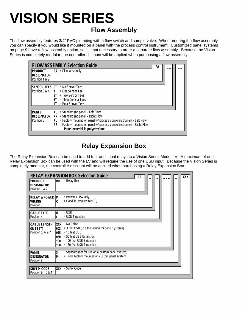
The flow assembly features 3/4" PVC plumbing with a flow switch and sample valve. When ordering the flow assembly you can specify if you would like it mounted on a panel with the process control instrument. Customized panel systems on page 9 have a flow assembly option, so it is not necessary to order a separate flow assembly. Because the Vision Series is completely modular, the controller discount will be applied when purchasing a flow assembly.
FA _ _ - _ _PRODUCT FA = Flow AssemblyDESIGNATORPosition 1 & 2
SENSOR TEES 0T = No Sensor TeesPosition 3 & 4 1T = One Sensor Tee
2T = Two Sensor Tees3T = Three Sensor Tees4T = Four Sensor Tees
PANEL XL = Standard (no panel) - Left FlowDESIGNATOR XR = Standard (no panel) - Right FlowPosition 5 PL = Factory mounted on panel w/ process control instrument - Left Flow
PR = Factory mounted on panel w/ process control instrument - Right Flow Panel material is polyethylene
FLOW ASSEMBLY Selection Guide
Relay Expansion Box The Relay Expansion Box can be used to add four additional relays to a Vision Series Model LV. A maximum of one Relay Expansion Box can be used with the LV and will require the use of one USB input. Because the Vision Series is completely modular, the controller discount will be applied when purchasing a Relay Expansion Box.
RB - _ _ _ _ _ _ - XXXPRODUCT RB = Relay BoxDESIGNATORPosition 1 & 2
RELAY & POWER P = Prewire (115V only)WIRING C = Conduit (required for CE)Position 3
CABLE TYPE U = USBPosition 4 E = USB Extension
CABLE LENGTH XXX No Cable(IN FEET) 003 = 3 feet USB (use this option for panel systems)Position 5, 6 & 7 015 = 15 feet USB
050 = 50 feet USB Extension100 100 feet USB Extension150 = 150 feet USB Extension
PANEL S Standard (not for use on a custom panel system)DESIGNATOR P = To be factory mounted on custom panel systemPosition 8
SUFFIX CODE XXX = Suffix CodePosition 9, 10 & 11
RELAY EXPANSION BOX Selection Guide
9
VISION SERIES USB Expansion Hub
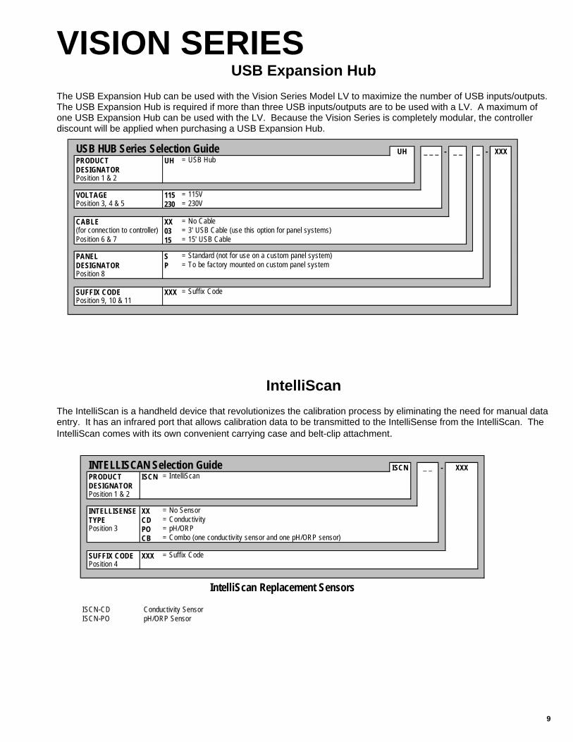
The USB Expansion Hub can be used with the Vision Series Model LV to maximize the number of USB inputs/outputs. The USB Expansion Hub is required if more than three USB inputs/outputs are to be used with a LV. A maximum of one USB Expansion Hub can be used with the LV. Because the Vision Series is completely modular, the controller discount will be applied when purchasing a USB Expansion Hub.
UH _ _ _ - _ _ _ - XXXPRODUCT UH = USB HubDESIGNATORPosition 1 & 2
VOLTAGE 115 = 115VPosition 3, 4 & 5 230 = 230V
CABLE XX = No Cable(for connection to controller) 03 = 3' USB Cable (use this option for panel systems)Position 6 & 7 15 = 15' USB Cable
PANEL S = Standard (not for use on a custom panel system)DESIGNATOR P = To be factory mounted on custom panel systemPosition 8
SUFFIX CODE XXX = Suffix CodePosition 9, 10 & 11
USB HUB Series Selection Guide
IntelliScan The IntelliScan is a handheld device that revolutionizes the calibration process by eliminating the need for manual data entry. It has an infrared port that allows calibration data to be transmitted to the IntelliSense from the IntelliScan. The IntelliScan comes with its own convenient carrying case and belt-clip attachment.
ISCN _ _ - XXXPRODUCT ISCN = IntelliScanDESIGNATORPosition 1 & 2
INTELLISENSE XX = No SensorTYPE CD = ConductivityPosition 3 PO = pH/ORP
CB = Combo (one conductivity sensor and one pH/ORP sensor)
SUFFIX CODE XXX = Suffix CodePosition 4
ISCN-CD Conductivity SensorISCN-PO pH/ORP Sensor
INTELLISCAN Selection Guide
IntelliScan Replacement Sensors

VISION SERIES IntelliSense
By converting an analog sensor input to a digital signal, the IntelliSense provides auto sensor recognition, eliminates drifting potential and allows travel of up to 150 feet (multipurpose IntelliSense has a max of 15'). Each of the 5 avail-able sensory heads are color coded and measure a multitude of variables.
IS _ _ - XXXPRODUCT IS = IntelliSenseDESIGNATORPosition 1 & 2
INTELLISENSE C = Conductivity (light gray)TYPE P = pH (blue)Position 3 O = ORP (red)
M = Multipurpose (MPIO) (orange)
CONNECTION TYPE U = USBPosition 4 E = USB Extension
SUFFIX CODE XXX = Suffix CodePosition 5
INTELLISENSE Selection Guide
Part No. Description Applicable Model CB01-1020 I/O Board UVCB01-1030 I/OI Board with communications (requires modem or Ethernet module) UVCB01-1010 I/O Board LVCB01-1022 I/O Board with communications (requires modem or Ethernet module) LVCB01-1026 Modem Module UV/LVCB01-1025 Ethernet Module UV/LVCB01-1115 Power Supply Board UV/LVLE01-3000 Front Panel Assembly UVLE01-2000 Front Panel Assembly LV
Cables
Part No. Description Applicable Model U003 USB Cable - 3' UV/LVU015 USB Cable - 15' UV/LVR050 50' cable to be used for USB Extension models only UV/LVR100 100' cable to be used for USB Extension models only UV/LVR150 150' cable to be used for USB Extension models only UV/LV
Part No. Description Applicable Model HA01-1002 IntelliSense Adapter IntelliSenseDA01-1000 USB to RS422 Adapter UV/LV05-053-18 5 Amp Fuse UV/LVSMK036 Submersible Mounting Kit - 36 IntelliSenseSMK060 Submersible Mounting Kit - 60 IntelliSenseSMK120 Submersible Mounting Kit - 120 IntelliSenseUSBXDR-000 USB Ethernet Extender Azzy UV/LV
Boards/Communications
Miscellaneous Parts
11
VISION SERIES Custom Panel Systems
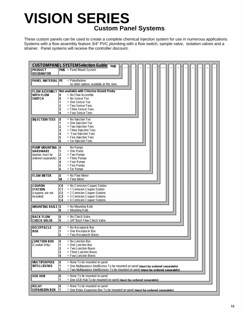
These custom panels can be used to create a complete chemical injection system for use in numerous applications. Systems with a flow assembly feature 3/4" PVC plumbing with a flow switch, sample valve, isolation valves and a strainer. Panel systems will receive the controller discount.
PMS - _ _ - _ _ _ _ - _ _ _ _ - _ _ _ _ _PRODUCT PMS = Panel Mount SystemDESIGNATOR
PANEL MATERIAL PE = Polyethyleneno other options available at this time
FLOW ASSEMBLY Not available with Chlorine Dioxid ProbeWITH FLOW X = No Flow AssemblySWITCH 0 = No Sensor Tee
1 = One Sensor Tee2 = Two Sensor Tees3 = Three Sensor Tees4 = Four Sensor Tees
INJECTION TEES X = No Injection Tee1 = One Injection Tee2 = Two Injection Tees3 = Three Injection Tees4 = Four Injection Tees5 = Five Injection Tees6 = Six Injection Tees
PUMP MOUNTING X No PumpsHARDWARE 1 = One Pump(pumps must be 2 = Two Pumpsordered separately) 3 = Three Pumps
4 = Four Pumps5 = Five Pumps6 = Six Pumps
FLOW METER X = No Flow MeterM = Flow Meter
COUPON C0 = No Corrosion Coupon StationSTATION C1 = 1 Corrosion Coupon Station(coupons are not C2 = 2 Corrosion Coupon Stationsincluded) C3 = 3 Corrosion Coupon Stations
C4 = 4 Corrosion Coupon Stations
MOUNTING RAILS X = No Mounting RailsR = Mounting Rails
BACK FLOW X = No Check ValveCHECK VALVE V = 3/4" Back Flow Check Valve
RECEPTACLE X = No Receptacle BoxBOX 1 = One Receptacle Box
2 = Two Receptacle Boxes
JUNCTION BOX X = No Junction Box(Conduit Only) 1 = One Junction Box
2 = Two Junction Boxes3 = Three Junction Boxes4 = Four Junction Boxes
MULTIPURPOSE X = None To be mounted on panelINTELLISENSE 1 = One Multipurpose IntelliSense To be mounted on panel (must be ordered separately)
2 = Two Multipurpose IntelliSenses To be mounted on panel (must be ordered separately)
USB HUB X = None To be mounted on panel1 = One USB Hub To be mounted on panel (must be ordered separately)
RELAY X = None To be mounted on panelEXPANSION BOX 1 = One Relay Expansion Box To be mounted on panel (must be ordered separately)
CUSTOM PANEL SYSTEM Selection Guide
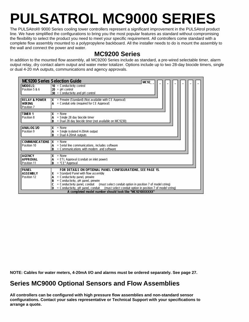
PULSATROL MC9000 SERIES The PULSAtrol® 9000 Series cooling tower controllers represent a significant improvement in the PULSAtrol product line. We have simplified the configurations to bring you the most popular features as standard without compromising the flexibility to select the product you need to meet your specific requirement. All controllers come standard with a complete flow assembly mounted to a polypropylene backboard. All the installer needs to do is mount the assembly to the wall and connect the power and water.
MC9200 Series In addition to the mounted flow assembly, all MC9200 Series include as standard, a pre-wired selectable timer, alarm output relay, dry contact alarm output and water meter totalizer. Options include up to two 28-day biocide timers, single or dual 4-20 mA outputs, communications and agency approvals.
NOTE: Cables for water meters, 4-20mA I/O and alarms must be ordered separately. See page 27. Series MC9000 Optional Sensors and Flow Assemblies All controllers can be configured with high pressure flow assemblies and non-standard sensor configurations. Contact your sales representative or Technical Support with your specifications to arrange a quote.
MC92_ _ _ _ _ _ _ _MODELS: 10 = Conductivity controlPosition 5 & 6 20 = pH control
30 = Conductivity and pH control
RELAY & POWER X = Prewire (Standard) (Not available with CE Approval)WIRING A = Conduit only (required for CE Approval)Position 7
TIMER 1 X = NonePosition 8 A = Single 28 day biocide timer
B = Dual 28 day biocide timer (not available on MC9230)
ANALOG I/O X = NonePosition 9 A = Single isolated 4-20mA output
B = Dual 4-20mA outputs
COMMUNICATIONS X = NonePosition 10 A = Serial line communications, includes software
B = Communications with modem and software
AGENCY X = NoneAPPROVAL A = ETL Approval (conduit on inlet power)Position 11 B = "CE" Approval
PANEL FOR DETAILS ON OPTIONAL PANEL CONFIGURATIONS, SEE PAGE 15.ASSEMBLY X = Standard Panel with flow assemblyPosition 12 A = Conductivity panel, prewire
B = Conductivity, pH panel, prewireC = Conductivity panel, conduit (must select conduit option in position 7 of model string)D = Conductivity, pH panel, conduit (must select conduit option in position 7 of model string)
MC9200 Series Selection Guide
A completed model number should look like "MC9210XXXXXX"
13
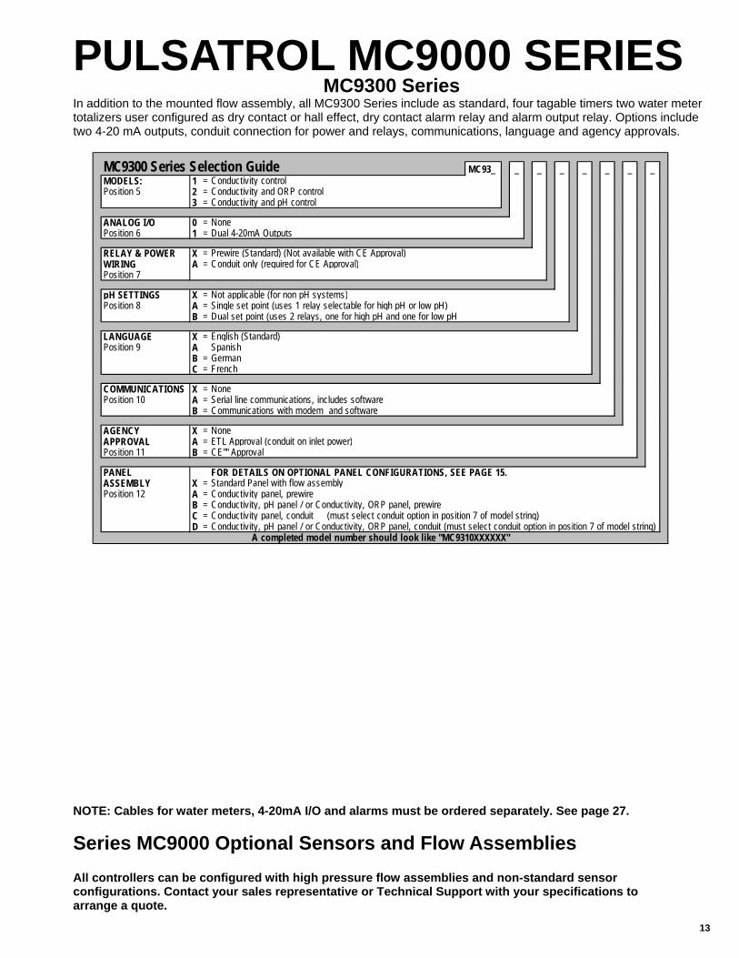
PULSATROL MC9000 SERIES MC9300 Series
In addition to the mounted flow assembly, all MC9300 Series include as standard, four tagable timers two water meter totalizers user configured as dry contact or hall effect, dry contact alarm relay and alarm output relay. Options include two 4-20 mA outputs, conduit connection for power and relays, communications, language and agency approvals.
NOTE: Cables for water meters, 4-20mA I/O and alarms must be ordered separately. See page 27. Series MC9000 Optional Sensors and Flow Assemblies All controllers can be configured with high pressure flow assemblies and non-standard sensor configurations. Contact your sales representative or Technical Support with your specifications to arrange a quote.
MC93_ _ _ _ _ _ _ _MODELS: 1 = Conductivity controlPosition 5 2 = Conductivity and ORP control
3 = Conductivity and pH control
ANALOG I/O 0 = NonePosition 6 1 = Dual 4-20mA Outputs
RELAY & POWER X = Prewire (Standard) (Not available with CE Approval)WIRING A = Conduit only (required for CE Approval)Position 7
pH SETTINGS X = Not applicable (for non pH systems)Position 8 A = Single set point (uses 1 relay selectable for high pH or low pH)
B = Dual set point (uses 2 relays, one for high pH and one for low pH
LANGUAGE X = English (Standard)Position 9 A Spanish
B = GermanC = French
COMMUNICATIONS X = NonePosition 10 A = Serial line communications, includes software
B = Communications with modem and software
AGENCY X = NoneAPPROVAL A = ETL Approval (conduit on inlet power)Position 11 B = CE"" Approval
PANEL FOR DETAILS ON OPTIONAL PANEL CONFIGURATIONS, SEE PAGE 15.ASSEMBLY X = Standard Panel with flow assemblyPosition 12 A = Conductivity panel, prewire
B = Conductivity, pH panel / or Conductivity, ORP panel, prewireC = Conductivity panel, conduit (must select conduit option in position 7 of model string)D = Conductivity, pH panel / or Conductivity, ORP panel, conduit (must select conduit option in position 7 of model string)
MC9300 Series Selection Guide
A completed model number should look like "MC9310XXXXXX"

PULSATROL MC9000 SERIES
NOTE: Cables for water meters, 4-20mA I/O and alarms must be ordered separately. See page 27. Series MC9000 Optional Sensors and Flow Assemblies All controllers can be configured with high pressure flow assemblies and non-standard sensor configurations. Contact your sales representative or Technical Support with your specifications to arrange a quote.
MC9500 Series In addition to the mounted flow assembly, all 9500 Series include as standard, four tagable timers, two water meter totalizers user configured as dry contact or hall effect, four drum level inputs, dry contact alarm relay and alarm output relay. Options include up to four 4-20 mA inputs and outputs, conduit connection for power and relays, communica-tions, language and agency approvals.
MC95_ _ _ _ _ _ _ _MODELS: 1 = Conductivity controlPosition 5 2 = Conductivity and ORP
3 = Conductivity and pH control4 = Conductivity, make-up conductivity and pH control 5 = Conductivity (with make-up), pH and ORP6 = Dual Conductivity for use on open loop (tower) and closed loop (chiller)7 = Dual Conductivity for use on dual cooling tower systems
4-20mA 0 = 0 Inputs, 0 OutputsINPUTS/OUTPUTS 1 = 0 Inputs, 2 OutputsPosition 6 2 = 0 Inputs, 4 Outputs
3 = 2 Inputs, 0 Outputs4 = 2 Inputs, 2 Outputs5 = 2 Inputs, 4 Outputs6 = 4 Inputs, 0 Outputs7 = 4 Inputs, 2 Outputs8 = 4 Inputs, 4 Outputs
RELAY & POWER X = Prewire (Standard) (Not available with CE Approval)WIRING A = Conduit only (required for CE Approval)Position 7
pH SETTINGS X = Not applicable (for non pH systems)Position 8 A = Single set point (uses 1 relay selectable for high pH or low pH)
B = Dual set point (uses 2 relays, one for high pH and one for low pH
LANGUAGE X = English (Standard)Position 9 A Spanish
B = GermanC = French
COMMUNICATIONS X = NonePosition 10 A = Serial line communications, includes software
B = Communications with modem and software
AGENCY X = NoneAPPROVAL A = ETL Approval (conduit on inlet power)Position 11 B = CE"" Approval
PANEL FOR DETAILS ON OPTIONAL PANEL CONFIGURATIONS, SEE PAGE 15.ASSEMBLY X = Standard Panel with flow assemblyPosition 12 A = Conductivity panel, prewire
B = Conductivity, pH panel / or Conductivity, ORP panel, prewireC = Conductivity panel, conduit (must select conduit option in position 7 of model string)D = Conductivity, pH panel / or Conductivity, ORP panel, conduit (must select conduit option in position 7 of model string)
MC9500 Series Selection Guide
A completed model should look like " MC9510XXXXXX"

15
OPTIONAL PANEL ASSEMBLIES Series MC9000 Optional Panel Assemblies
All MC9000 Systems come standard with a flow assembly and sensor tee mounted to a sturdy polypropylene panel. Optional configurations of the panel can be selected to create a complete chemical injection system. These sys-tems are designed to simplify installation and reduce problems caused by a poor installation. Each panel includes 3/4" plumbing with the following features: • Quick disconnect sensor mounting tees • Chemical injection points • Ball valves on the inlet and outlet • Back flow check valve • Flow strainer • Mounting brackets for chemical metering pumps Select from one of the following configurations and insert the op-tion code into digit #12 when configuring your controller.
Note: Pumps must be ordered separately. If ordering PULSAtron Pumps in conjunction with a panel, use suffix code PFB in place of the XXX in the last three digits and the pumps will be installed on the panel during assembly. If you already have a suffix code, then order your standard suffix code followed by PF. For example, if your suffix code is G15, then you would order G15PF when ordering in conjunction with a panel.
Conductivity Panel - Prewire Enter Option "A" in position 12 of the PULSAtrol 9000 Model String. Panel features 'quick-disconnect' sensor tee; three injectors for inhibitor and biocides; and mounting brackets for three pumps.
Conductivity, pH, ORP Panel - Prewire* Enter Option "B" in position 12 of the PULSAtrol 9000 Model String. Panel features 'quick-disconnect' sensor tees for all parameters; three injectors for inhibitor and biocides; and mounting brackets for three pumps.
Conductivity Panel - Conduit Enter Option "C" in position 12 of the PULSAtrol 9000 Model String. This option also requires option 'A' in position 7 for conduit. Panel features 'quick-disconnect' sensor tee; three injectors for inhibitor and biocides; and mounting hardware for three pumps. Pump and bleed relays are wired into a watertight outlet box with a splash guard cover.
Conductivity, pH, ORP Panel - Conduit* Enter Option "D" in position 12 of the PULSAtrol 9000 Model String. This option also requires option 'A' in position 7 for conduit. Panel features 'quick-disconnect' sensor tees for all parameters; three injectors for inhibitor and biocides; and mounting hardware for three pumps. Pump and bleed relays are wired into a watertight outlet box with a splash guard cover. *NOTE: The sensor tee is capped on systems that do not require it.

MC9000 SENSORS
MCT1_ _ _ _ _ _ _ _ _ _ _ _MODELS: 20 = MCT1_ _ (pH) control with high/low alarm indicator and limit timerPosition 5 & 6 30 = MCT1_ _ (ORP) control with high/low alarm indicator and limit timer
AVAILABLE A = Conduit (Required for 220V, ""PI""s and ""FW""s)OPTIONS B = Mounted flow assembly (not required on prefab's)Position 7 thru 16 B2 = High pressure flow assy for pH, 250 psi Max.as needed B4 = High pressure flow assy for orp, 250 psi Max.
C = Selectable timer: %, limit, pulse, % post blow downD = Alarm output relay (limit one per unit)E = 28 day single biocide w/ bleed lockout & pre-bleedK = Alarm dry contactM3 = 4-20 mA isolated proportional programmable outputR = ETL ApprovalR1 = CE Mark (option A required)
W (1) = Private Label
Notes: (1) First time private label customers need to contact the factory or sales representative for information.
MCT Series Selection Guide
pH/ORP CONTROL
Item No. Application Note:04-600-92-1 Conductivity MC9000 Series replacement sensor. Stainless steel electrodes, 12" cable terminated with DIN plug.
04-600-92-2Conductivity or Make-up
MC9000 Series replacement sensor. Stainless steel electrodes, 120" cable terminated with DIN plug.
04-600-93-1 Conductivity MC9000 Series replacement sensor. CE approved, Stainless steel electrodes, 12" cable terminated with DIN plug.
04-600-93-2Conductivity or Make-up
MC9000 Series replacement sensor. CE approved, Stainless steel electrodes, 120" cable terminated with DIN plug.
04-000-00 pH MC9000 replacement sensor. Epoxy body, dual junction, 42mm extension with 3 ft. cable.04-000-01 pH MC9000 replacement sensor. Epoxy body, dual junction, 42mm extension with 10 ft. cable.04-000-10 ORP MC9000 replacement sensor. Epoxy body, platinum band, single junction, 42mm extension with 3 ft. cable.04-000-11 ORP MC9000 replacement sensor. Epoxy body, platinum band, single junction, 42mm extension with 10 ft. cable.04-300-92 Flow Flow switch, 3/4" with 18" cable terminated with DIN plug.04-300-94 Flow Flow switch, 3/4" with 120" cable terminated with DIN plug.04-300-93 Flow Flow switch, CE approved, 3/4" with 18" cable terminated with DIN plug.04-300-95 Flow Flow switch, CE approved, 3/4" with 120" cable terminated with DIN plug.
16-171-81-216-171-81-116-171-81-4 Adjustable to 60" with 3 ft. cable
Series MC9000 Replacement Sensors
MC9500 ACCESSORIES
Single Point Level Wands
Adjustable to 26" with 3 ft. cableAdjustable to 42" with 3 ft. cable

17
MicroVision SERIES MicroVision Series
The MicroVision controller series features is innovative Toroidal sensor technology. Toroidal sensors are not suscepti-ble to fouling and eliminate the need for routine cleaning and calibration. The MicroVision is designed specifically for cooling tower applications. The MicroVision is a microprocessor-based conductivity controller with selectable timer and dual biocide control. The MicroVision controller comes standard with selectable timer, Dry contact/Hall Effect water meter input, dual biocide with pre-bleed, lockout, inhibitor interface, and four programmable start times per biocide, 4-20mA output, dry contact alarm output and 3 drum level inputs. The base unit comes with the controller, toroidal sensor with signal cable, and a power cord. Optional features such as a sensor mounting tee, pre-wired pigtails on the relays, and a pre-wired flow switch are available to make installation quick and easy. A 15' signal cable is standard, up to 100’ optional, on models without a flowswitch, and a 3' cable is standard on models with a flowswitch.
MVS _ _ _ - _ _ _ _ _PRODUCT MVS = MicroVision Toroidal Conductivity Cooling Tower ControllerDESIGNATORPosition 1, 2 & 3
VOLTAGE 1 = 115 voltPosition 4 2 = 230 volt (no prewired power cord or relays available)
POWER WIRING X = Conduit connections ( required for 230 VAC)Position 5 P = Prewired power cord and pigtails
PANELS X = No Panel and No Flow assemblyPosition 6 F = Flow assembly, No Panel
A = Standard Panel & Flow AssemblyB = Panel & Flow Assy, 1 Pump Mount, strainer, sensor tee, inj tee & railsC = Panel & Flow Assy, 2 Pump Mount, strainer, sensor tee, 2 inj tees & railsD = Panel & Flow Assy, 3 Pump Mount, strainer, sensor tee, 3 inj tees & rails
SUFFIX CODE XXX = Suffix CodePosition 7, 8 & 9 750 = 3/4" Back Flow Check Valve
PC025 = 25 Feet (7.6m)PC050 = 50 Feet (15.2m)PC075 = 75 Feet (22.8m)PC100 = 100 Feet (30.4m)
MicroVision Selection Guide
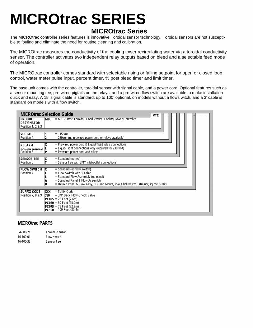
MICROtrac SERIES
MTC _ _ _ _ - _ _ _ _ _PRODUCT MTC = MICROtrac Toroidal Conductivity Cooling Tower ControllerDESIGNATORPosition 1, 2 & 3
VOLTAGE 1 = 115 voltPosition 4 2 = 230volt (no prewired power cord or relays available)
X = Prewired power cord & Liquid-Tight relay connections L = Liquid-Tight connections only (required for 230 volt)
Position 5 P = Prewired power cord and relays
SENSOR TEE X = Standard (no tee)Position 6 T = Sensor Tee with 3/4"" inlet/outlet connections
FLOW SWITCH X = Standard (no flow switch)Position 7 F = Flow Switch with 3' cable
L = Standard Flow Assembly (no panel)A = Standard Panel & Flow AssemblyB = Deluxe Panel & Flow Assy, 1 Pump Mount, in/out ball valves, strainer, inj tee & rails
SUFFIX CODE XXX = Suffix CodePosition 7, 8 & 9 750 = 3/4" Back Flow Check Valve
PC025 = 25 Feet (7.6m)PC050 = 50 Feet (15.2m)PC075 = 75 Feet (22.8m)PC100 = 100 Feet (30.4m)
04-000-21 Toroidal sensor16-100-01 Flow switch16-100-33 Sensor Tee
MICROtrac Selection Guide
RELAY & POWER WIRING
MICROtrac PARTS
MICROtrac Series The MICROtrac controller series features is innovative Toroidal sensor technology. Toroidal sensors are not suscepti-ble to fouling and eliminate the need for routine cleaning and calibration. The MICROtrac measures the conductivity of the cooling tower recirculating water via a toroidal conductivity sensor. The controller activates two independent relay outputs based on bleed and a selectable feed mode of operation. The MICROtrac controller comes standard with selectable rising or falling setpoint for open or closed loop control, water meter pulse input, percent timer, % post bleed timer and limit timer. The base unit comes with the controller, toroidal sensor with signal cable, and a power cord. Optional features such as a sensor mounting tee, pre-wired pigtails on the relays, and a pre-wired flow switch are available to make installation quick and easy. A 15' signal cable is standard, up to 100’ optional, on models without a flows witch, and a 3' cable is standard on models with a flow switch.

19
DCS900 SERIES DCS900 Series
The DCS900 was designed specifically to control conductivity and feed inhibitor in cooling tower systems. With three timer modes and optional water meter input, the DCS900 offers the best value in a stand-alone control sys-tem. Sensor and flow switch are connected to the controller via DIN plug type connectors -eliminating the need to re-move the front cover for wiring. Each system comes standard with a flow switch, 4-electrode stainless steel sensor, bleed relay and control relay for controlling a chemical feed pump. The DCS902 includes a water meter totalizer that is user configurable as a dry con-tact or Hall Effect. The mounted flow option provides a rugged polypropylene back board onto which the flow / sensor assemblies and controller are mounted.
1. Controller and flow assembly mounted onto a polypropylene back board. Flow switch and sensor cords cut to an appropriate length. 2. Controller and flow assembly mounted onto a polypropylene back board. Flow switch and sensor cords cut to appro-priate length. Power and relay outputs accessable to the electrical contractor through a junction box mounted onto the back board.
ACT SERIES
DCS90_ _ _ XMODELS 1 = No water meter input, % T, % Post and Limit Timer
2 = Water Meter Input (includes 3 ft. cable), Pulse Timer, % T, % Post and Limit Timer
ELECTRICAL X = 115 VAC 50/60 Hz, ETL ApprovalA = 230 VAC 50/60 Hz, CE Approvals (Conduit Required)
FLOW X = Flow switch and tee with 8.5' cable (Standard)A = Mounted Flow Assembly, Pre-wire (see note 1)B = Mounted Flow Assembly, Conduit (see note 2)
SENSOR X = Stainless Steel Sensor (Standard)A = Carbon Graphite Sensor
DCS900 Series Selection Guide
Item No. Description04-600-34 DCS900 replacement sensor. Stainless steel, 18" cable terminated with DIN plug.04-600-38 DCS900 replacement sensor. Carbon Graphite, 18" cable terminated with DIN plug.04-600-32 DCS900 replacement sensor. Stainless steel, 7 ft. cable terminated with DIN plug.04-600-36 DCS900 replacement sensor. Carbon Graphite, 7 ft. cable terminated with DIN plug.
Series DCS900 Replacement Sensors
_ _ _ _ _ _MODEL: ACT102 = Analog Meter Conductivity Controller SelectablePosition 1 thru 6 Dual Scale 0-2500 and 0-5000 µs/cm
AVAILABLE OPTIONS A = ConduitPosition 7 thru 12 B = Flow assemblyas needed C = Lockout timer
P = 220v, 50/60 Hz service (option "A" required) V = Agency Approval US/CanadaV1(1) = Agency Approval ""CE""W (2) = Private Label
Notes: (1) Option "A" (conduit) and option "P" (220V) required. (2) First time private label customers need to contact the factory or sales representative for information.
04-600-02 Conductivity; Stainless Steel with 10' cable
ACT Series Selection Guide ACT102
A completed model should look like "ACT102BC"
ACT Replacement Sensor
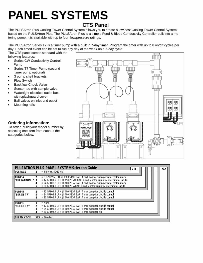
PANEL SYSTEMS CTS Panel
The PULSAtron Plus Cooling Tower Control System allows you to create a low cost Cooling Tower Control System based on the PULSAtron Plus. The PULSAtron Plus is a simple Feed & Bleed Conductivity Controller built into a me-tering pump. It is available with up to four flow/pressure ratings. The PULSAtron Series T7 is a timer pump with a built in 7-day timer. Program the timer with up to 8 on/off cycles per day. Each timed event can be set to run any day of the week on a 7-day cycle. The CTS panel comes standard with the following features: • Series CW Conductivity Control Pump • Series T7 Timer Pump (second timer pump optional) • 3 pump shelf brackets • Flow Switch • Backflow Check Valve • Sensor tee with sample valve • Watertight electrical outlet box with splashguard cover • Ball valves on inlet and outlet • Mounting rails
Ordering Information: To order, build your model number by selecting one item from each of the categories below.
CTS_ _ _ _ XXXVOLTAGE 2 = 115 volt, 50/60 Hz
PUMP A 2 = 6 GPD/.95 LPH @ 150 PSI/10 BAR, Cond. control pump w/ water meter inputs"PULSATRON +" 3 = 12 GPD/1.9 LPH @ 150 PSI/10 BAR, Cond. control pump w/ water meter inputs
4 = 24 GPD/3.8 LPH @ 100 PSI/7 BAR, Cond. control pump w/ water meter inputs6 = 30 GPD/4.7 LPH @ 100 PSI/7BAR, Cond. control pump w/ water meter inputs
PUMP B 2 = 12 GPD/1.9 LPH @ 100 PSI/7 BAR, Timer pump for biocide control"SERIES T7" 3 = 24 GPD/3.8 LPH @ 100 PSI/7 BAR, Timer pump for biocide control
4 = 30 GPD/4.7 LPH @ 100 PSI/7 BAR, Timer pump for biocide control
PUMP C 0 = None"SERIES T7"" 2 = 12 GPD/1.9 LPH @ 100 PSI/7 BAR, Timer pump for biocide control
3 = 24 GPD/3.8 LPH @ 100 PSI/7 BAR, Timer pump for biocide control4 = 30 GPD/4.7 LPH @ 100 PSI/7 BAR, Timer pump for bio
SUFFIX CODE XXX = Standard
PULSATRON PLUS PANEL SYSTEM Selection Guide
21
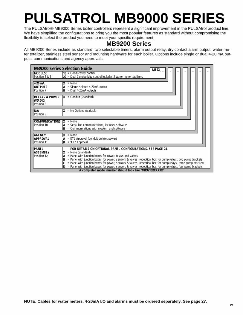
PULSATROL MB9000 SERIES The PULSAtrol® MB9000 Series boiler controllers represent a significant improvement in the PULSAtrol product line. We have simplified the configurations to bring you the most popular features as standard without compromising the flexibility to select the product you need to meet your specific requirement.
MB9200 Series All MB9200 Series include as standard, two selectable timers, alarm output relay, dry contact alarm output, water me-ter totalizer, stainless steel sensor and mounting hardware for each boiler. Options include single or dual 4-20 mA out-puts, communications and agency approvals.
NOTE: Cables for water meters, 4-20mA I/O and alarms must be ordered separately. See page 27.
MB92_ _ _ _ _ _ _ _MODELS: 10 = Conductivity controlPosition 5 & 6 20 = Dual Conductivity control includes 2 water meter totalizers
4-20 mA X = NoneOUTPUTS A = Single isolated 4-20mA outputPosition 7 B = Dual 4-20mA outputs
RELAYS & POWER X = Conduit (Standard) WIRINGPosition 8
N/A X = No Options AvailablePosition 9
COMMUNICATIONS X = NonePosition 10 A = Serial line communications, includes software
B = Communications with modem and software
AGENCY X = NoneAPPROVAL A = ETL Approval (conduit on inlet power)Position 11 B = "CE" Approval
PANEL FOR DETAILS ON OPTIONAL PANEL CONFIGURATIONS, SEE PAGE 24.ASSEMBLY X = None (Standard)Position 12 A = Panel with junction boxes for power, relays and valves
B = Panel with junction boxes for power, sensors & valves, receptical box for pump relays, two pump bracketsC = Panel with junction boxes for power, sensors & valves, receptical box for pump relays, three pump bracketsD = Panel with junction boxes for power, sensors & valves, receptical box for pump relays, four pump brackets
MB9200 Series Selection Guide
A completed model number should look like "MB9210XXXXXX"
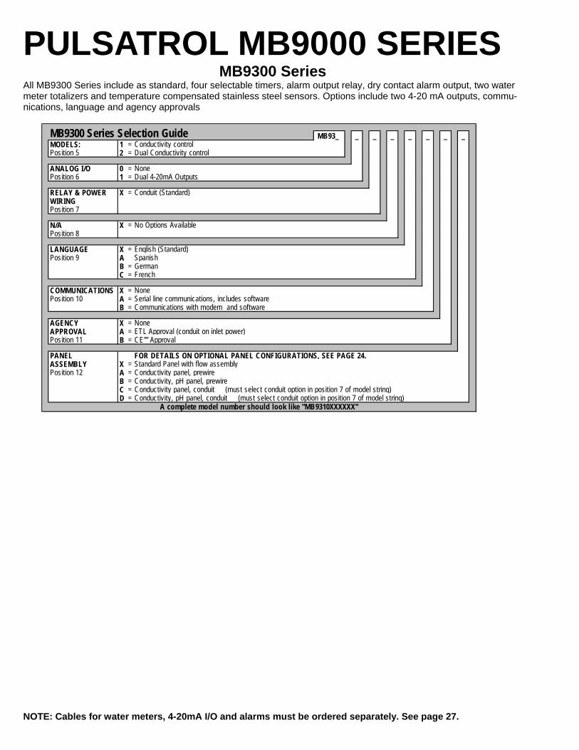
PULSATROL MB9000 SERIES MB9300 Series
All MB9300 Series include as standard, four selectable timers, alarm output relay, dry contact alarm output, two water meter totalizers and temperature compensated stainless steel sensors. Options include two 4-20 mA outputs, commu-nications, language and agency approvals
NOTE: Cables for water meters, 4-20mA I/O and alarms must be ordered separately. See page 27.
MB93_ _ _ _ _ _ _ _MODELS: 1 = Conductivity controlPosition 5 2 = Dual Conductivity control
ANALOG I/O 0 = NonePosition 6 1 = Dual 4-20mA Outputs
RELAY & POWER X = Conduit (Standard) WIRINGPosition 7
N/A X = No Options AvailablePosition 8
LANGUAGE X = English (Standard)Position 9 A Spanish
B = GermanC = French
COMMUNICATIONS X = NonePosition 10 A = Serial line communications, includes software
B = Communications with modem and software
AGENCY X = NoneAPPROVAL A = ETL Approval (conduit on inlet power)Position 11 B = CE"" Approval
PANEL FOR DETAILS ON OPTIONAL PANEL CONFIGURATIONS, SEE PAGE 24.ASSEMBLY X = Standard Panel with flow assemblyPosition 12 A = Conductivity panel, prewire
B = Conductivity, pH panel, prewireC = Conductivity panel, conduit (must select conduit option in position 7 of model string)D = Conductivity, pH panel, conduit (must select conduit option in position 7 of model string)
MB9300 Series Selection Guide
A complete model number should look like "MB9310XXXXXX"
23
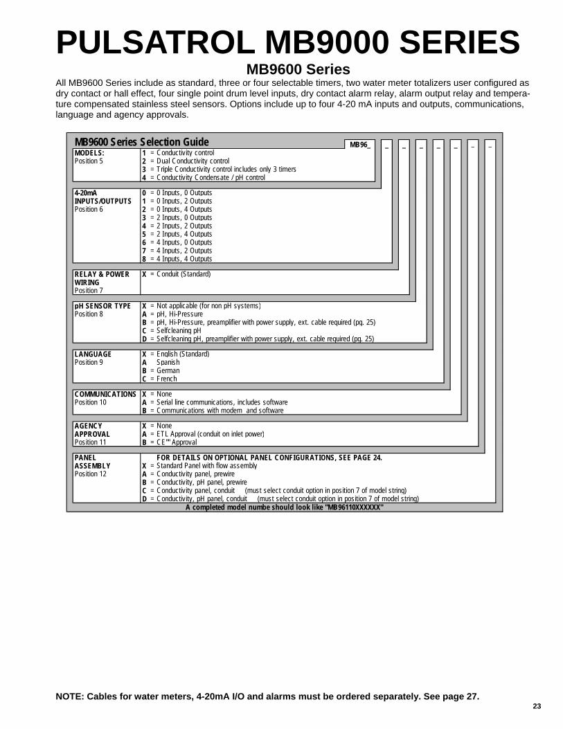
MB96_ _ _ _ _ _ _ _MODELS: 1 = Conductivity controlPosition 5 2 = Dual Conductivity control
3 = Triple Conductivity control includes only 3 timers4 = Conductivity Condensate / pH control
4-20mA 0 = 0 Inputs, 0 OutputsINPUTS/OUTPUTS 1 = 0 Inputs, 2 OutputsPosition 6 2 = 0 Inputs, 4 Outputs
3 = 2 Inputs, 0 Outputs4 = 2 Inputs, 2 Outputs5 = 2 Inputs, 4 Outputs6 = 4 Inputs, 0 Outputs7 = 4 Inputs, 2 Outputs8 = 4 Inputs, 4 Outputs
RELAY & POWER X = Conduit (Standard) WIRINGPosition 7
pH SENSOR TYPE X = Not applicable (for non pH systems)Position 8 A = pH, Hi-Pressure
B = pH, Hi-Pressure, preamplifier with power supply, ext. cable required (pg. 25)C = Selfcleaning pHD = Selfcleaning pH, preamplifier with power supply, ext. cable required (pg. 25)
LANGUAGE X = English (Standard)Position 9 A Spanish
B = GermanC = French
COMMUNICATIONS X = NonePosition 10 A = Serial line communications, includes software
B = Communications with modem and software
AGENCY X = NoneAPPROVAL A = ETL Approval (conduit on inlet power)Position 11 B = CE"" Approval
PANEL FOR DETAILS ON OPTIONAL PANEL CONFIGURATIONS, SEE PAGE 24.ASSEMBLY X = Standard Panel with flow assemblyPosition 12 A = Conductivity panel, prewire
B = Conductivity, pH panel, prewireC = Conductivity panel, conduit (must select conduit option in position 7 of model string)D = Conductivity, pH panel, conduit (must select conduit option in position 7 of model string)
MB9600 Series Selection Guide
A completed model numbe should look like "MB96110XXXXXX"
PULSATROL MB9000 SERIES
NOTE: Cables for water meters, 4-20mA I/O and alarms must be ordered separately. See page 27.
MB9600 Series All MB9600 Series include as standard, three or four selectable timers, two water meter totalizers user configured as dry contact or hall effect, four single point drum level inputs, dry contact alarm relay, alarm output relay and tempera-ture compensated stainless steel sensors. Options include up to four 4-20 mA inputs and outputs, communications, language and agency approvals.

OPTIONAL PANEL ASSEMBLIES Series MB9000 Optional Panel Assemblies All MB9000 Systems have the following panel mounted options available. Note: Pumps must be ordered separately. If ordering PULSAtron Pumps in conjunction with a panel, use suffix code PFB in place of the XXX in the last three digits and the pumps will be installed on the panel during assembly. If you already have a suffix code, then order your standard suffix code followed by PF. For example, if your suffix code is G15, then you would order G15PF when ordering in conjunction with a panel. Select from one of the following configurations and insert the option code into digit #12 when configuring your control-ler.
Panel with Junction Boxes Enter Option "A" in position 12 of the PULSAtrol 9000 Model String. Panel features junction for timers, alarms, blowdown, power and sensor connections. The number of junction boxes may vary depending on the controller model. Panel with Junction Boxes and Mounting Hardware for Two Pumps Enter Option "B" in position 12 of the PULSAtrol 9000 Model String. Panel features junction for timers, alarms, blowdown, power and sensor connections and mounting hardware for two pumps. The number of junction boxes may vary depending on the controller model. Panel with Junction Boxes and Mounting Hardware for Three Pumps Enter Option "C" in position 12 of the PULSAtrol 9000 Model String. Panel features junction for timers, alarms, blowdown, power and sensor connections and mounting hardware for three pumps. The number of junction boxes may vary depending on the controller model. Panel with Junction Boxes and Mounting Hardware for Four Pumps Enter Option "D" in position 12 of the PULSAtrol 9000 Model String. Panel features junction for timers, alarms, blowdown, power and sensor connections and mounting hardware for four pumps. The number of junction boxes may vary depending on the controller model.
25
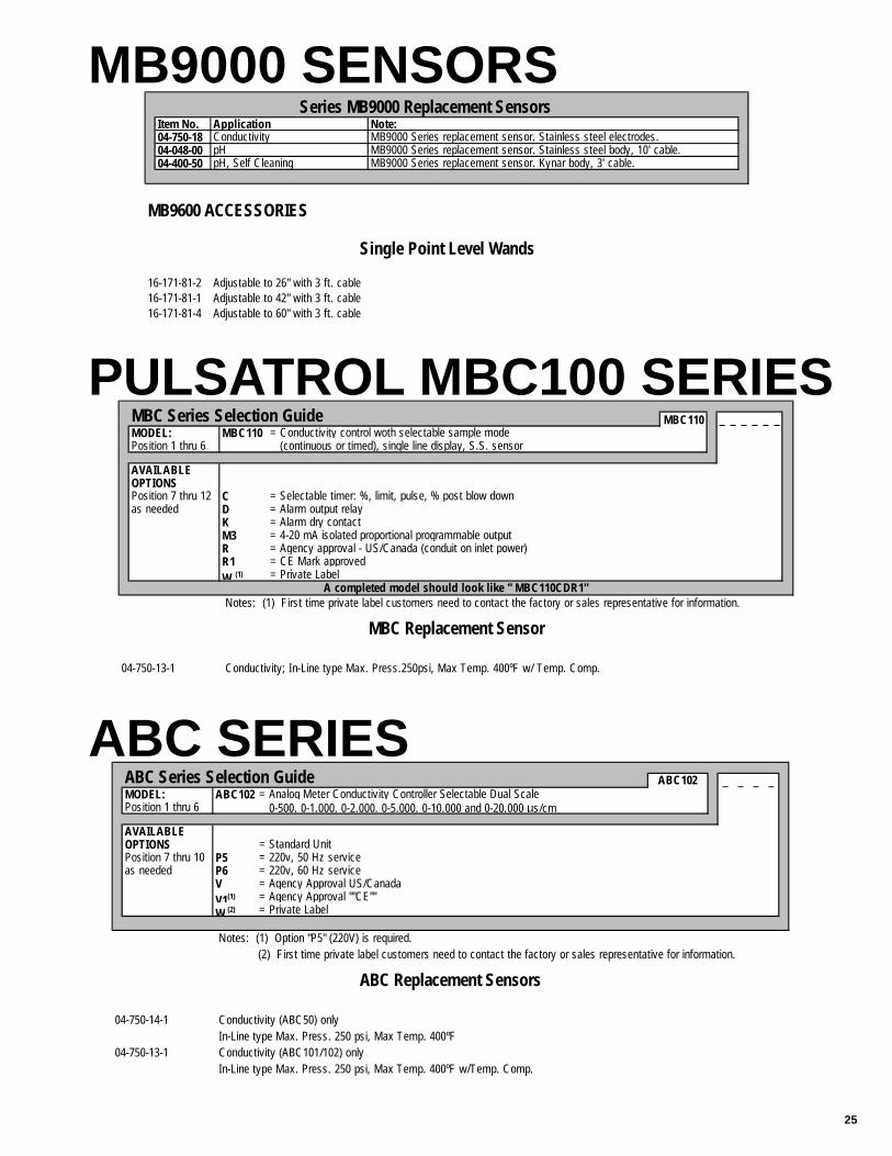
MB9000 SENSORS
PULSATROL MBC100 SERIES
ABC SERIES
Item No. Application Note:04-750-18 Conductivity MB9000 Series replacement sensor. Stainless steel electrodes.04-048-00 pH MB9000 Series replacement sensor. Stainless steel body, 10' cable.04-400-50 pH, Self Cleaning MB9000 Series replacement sensor. Kynar body, 3' cable.
16-171-81-2 Adjustable to 26" with 3 ft. cable16-171-81-1 Adjustable to 42" with 3 ft. cable16-171-81-4 Adjustable to 60" with 3 ft. cable
Series MB9000 Replacement Sensors
MB9600 ACCESSORIES
Single Point Level Wands
MBC110 _ _ _ _ _ _MODEL: MBC110 = Conductivity control woth selectable sample modePosition 1 thru 6 (continuous or timed), single line display, S.S. sensor
AVAILABLE OPTIONSPosition 7 thru 12 C = Selectable timer: %, limit, pulse, % post blow downas needed D = Alarm output relay
K = Alarm dry contactM3 = 4-20 mA isolated proportional programmable outputR = Agency approval - US/Canada (conduit on inlet power)R1 = CE Mark approvedW (1) = Private Label
Notes: (1) First time private label customers need to contact the factory or sales representative for information.
04-750-13-1 Conductivity; In-Line type Max. Press.250psi, Max Temp. 400ºF w/ Temp. Comp.
MBC Series Selection Guide
A completed model should look like " MBC110CDR1"
MBC Replacement Sensor
_ _ _ _MODEL: ABC102 = Analog Meter Conductivity Controller Selectable Dual ScalePosition 1 thru 6 0-500, 0-1,000, 0-2,000, 0-5,000, 0-10,000 and 0-20,000 µs/cm
AVAILABLE OPTIONS = Standard UnitPosition 7 thru 10 P5 = 220v, 50 Hz serviceas needed P6 = 220v, 60 Hz service
V = Agency Approval US/CanadaV1(1) = Agency Approval ""CE""W (2) = Private Label
Notes: (1) Option "P5" (220V) is required. (2) First time private label customers need to contact the factory or sales representative for information.
04-750-14-1 Conductivity (ABC50) onlyIn-Line type Max. Press. 250 psi, Max Temp. 400ºF
04-750-13-1 Conductivity (ABC101/102) onlyIn-Line type Max. Press. 250 psi, Max Temp. 400ºF w/Temp. Comp.
ABC Series Selection Guide ABC102
ABC Replacement Sensors

CABLES Some cables for the PULSAtrol 9000 and DCS 900 are ordered separately to provide you the opportunity to buy only the cables required for your application and cut to your specified length. Some cables, e.g. sensor and communications cables are included. Cables that come standard with the product are as follows: Sensor cables. All sensor cables are cut to the length required for installation into the provided flow assembly. If you order a dual system, the sensor that comes with the second flow assembly will be cut to 10 ft or 3 meters. Flow Switch cables. All flow switch cables are cut to length required for installation into the provided flow assembly. If you order a dual system, the sensor that comes with the second flow assembly will be cut to 10 ft or 3 meters. Communications cables. When you order the communications option, you will receive a 10 foot (3 meter) cable with a DIN connection on one end for plugging into the controller and a standard RJ-45 connection on the other end. If your communications option includes the modem, you will also receive an RJ-45 to RJ-11 adapter for connecting into a standard telephone jack. Optional cables that must be ordered separately are as follows: Levels – All four drum level inputs are available from a single DIN on the controller. When you order a cable for levels, one end is terminated with the mating DIN for connecting to the controller. The cable is 8-conductor twisted pair. The other end of the cable is terminated with 4 dual-pin Molex connectors, one set for each of the four drum levels. Water Meters – All water meters inputs are available from a single DIN on the controller. When you order a cable for water meters, one end is terminated with the mating DIN for connecting to the controller. The cable is 8-conductor twisted pair. The other end of the cable has no terminals. Color-coded stripped leads are available for wiring to your specific water meter. Analog (4-20mA) Inputs – All 4-20 mA inputs are available from a single DIN on the controller. When you order a ca-ble for 4-20mA inputs, one end is terminated with the mating DIN for connecting to the controller. The cable is 8-conductor twisted pair. The other end of the cable has no terminals. Color-coded stripped leads are available for wiring to your analog output device. Analog (4-20mA) Outputs – All 4-20 mA outputs are available from a single DIN on the controller. When you order a cable for 4-20mA outputs, one end is terminated with the mating DIN for connecting to the controller. The cable is 8-conductor twisted pair. The other end of the cable has no terminals. Color-coded stripped leads are available for wiring to your analog output device. Dry-contact Alarm – All dry contact alarm outputs are available from a single DIN on the controller. When you order cable for dry contact alarms, one end is terminated with the mating DIN for connecting to the controller. The cable is 8-conductor twisted pair. The other end of the cable has no terminals. Color-coded stripped leads are available for wiring to your alarm input. Extension cables for sensors – as stated, all sensors come with standard length cables. If you need to extend the length of cable for your sensor, you can order an extension cable up to the maximum distance allowed for proper op-eration. The cable will come with a DIN plug on one end and a DIN receptacle on the other. Extension cables for the flow switch – as stated, all flow switch sensors come with standard length cables. If you need to extend the length of cable for your flow switch, you can order an extension cable up to the maximum distance allowed for proper operation. The cable will come with a DIN plug on one end and a DIN receptacle on the other. Extension cables for single point drum levels – drum level wands come with 3 ft of cable terminated with a two-pin Molex receptacle that mates to one of the four drum level outputs on the level cable coming from the controller. If you need to extend the length of a single point drum level, you can order an extension cable up to the maximum distance allowed for proper operation. The cable will come with a 2-pin Molex receptacle on one end and a 2-pin Molex plug on the other.
27
Option 1 DIN Plug
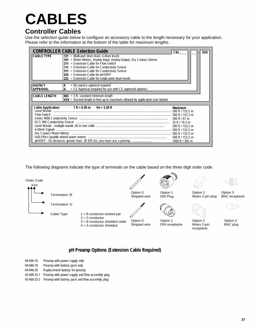
CABLES Controller Cables Use the selection guide below to configure an accessory cable to the length necessary for your application. Please refer to the information at the bottom of the table for maximum lengths.
The following diagrams indicate the type of terminals on the cable based on the three digit order code.
Option 0 Stripped wire
Option 0 Stripped wire
Option 1 DIN receptacle
Option 2 Molex 2-pin plug
Option 2 Molex 2-pin receptacle
Option 3 BNC receptacle
Option 3 BNC plug
Order Code XXX Termination 'B' Termination 'A' Cable Type 1 = 8-conductor twisted par 2 = 2-conductor 3 = 8-conductor shielded cable 4 = 2-conductor shielded
CBL_ _ _ _ _ - XXXCABLE TYPE 121 = Multi-port drum level, 4 drum levels
101 = Water Meters, Analog Input, Analog Output, Dry Contact Alarms211 = Extension Cable for Flow Switch111 = Extension Cable for Conductivity Sensor311 = Extension Cable for Conductivity Sensor433 = Extension Cable for pH/ORP222 = Extension Cable for single point drum levels
AGENCY X = No agency approval requiredAPPROVAL A = CE Approval (required for use with CE approved options)
CABLE LENGTH 003 = 3 ft. standard minimum lengthXXX = Desired length in feet up to maximum allowed by application (see below)
Cable Application 1 ft = 0.30 m 1m = 3.28 ft500 ft / 152.5 m500 ft / 152.5 m200 ft / 61 m35 ft / 10.5 m 500 ft / 152.5 m500 ft / 152.5 m500 ft / 152.5 m500 ft / 152.5 m1000 ft / 305 m
Maximum Level Wands .............................................................................................................................. Flow Switch ............................................................................................................................... Series 9000 Conductivity Sensor ............................................................................................... DCS 900 Conductivity Sensor .................................................................................................... Level Wands - multiple wands (4) in one cable ........................................................................ 4-20mA Signals ........................................................................................................................... Dry Contact Water Meters ........................................................................................................... Hall Effect (paddle wheel) water meters .................................................................................... pH/ORP - for distances greater than 30 ft/9.2m, you must use a preamp. ....................
CONTROLLER CABLE Selection Guide
04-046-16 Preamp with power supply only04-046-18 Preamp with battery pack only04-046-20 Replacement battery for preamp45-000-25-1 Preamp with power supply and flow assembly plug45-000-25-2 Preamp with battery pack and flow assembly plug
pH Preamp Options (Extension Cable Required)

PREFABRICATED SYSTEMS Prefabricated Systems
If a standard panel system does not fit your requirements, Pulsafeeder can fabricate a system tailored to your applica-tion. Some of the systems we have developed include: • Boiler Panels that include a boiler controller, metering pumps and water tight conduit boxes mounted to a polypro-
pylene or stainless panel. • Fully Enclosed system with pumps, controller and all electrical mounted into a Nema 4X enclosure for installations
in extreme conditions. • Floor or Wall mounted drum rack systems. • High Pressure Flow Assemblies. • Corrosion Monitoring systems that combine the features of a standard panel system with a coupon rack. For details on any of these systems contact your sales representative or the Pulsafeeder Technical Support team with your specifications to arrange a quote.
29
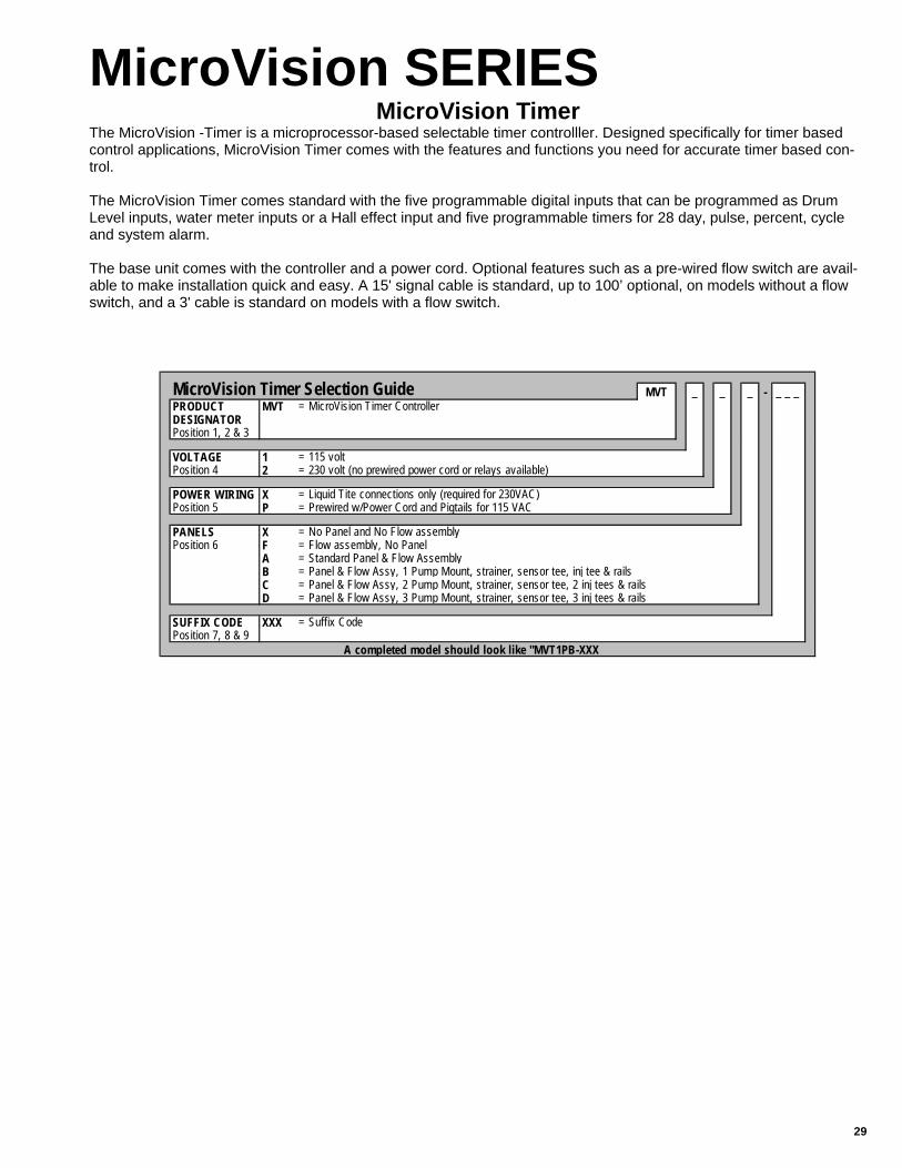
MVT _ _ _ - _ _ _ PRODUCT MVT = MicroVision Timer ControllerDESIGNATORPosition 1, 2 & 3
VOLTAGE 1 = 115 voltPosition 4 2 = 230 volt (no prewired power cord or relays available)
POWER WIRING X = Liquid Tite connections only (required for 230VAC)Position 5 P = Prewired w/Power Cord and Pigtails for 115 VAC
PANELS X = No Panel and No Flow assemblyPosition 6 F = Flow assembly, No Panel
A = Standard Panel & Flow AssemblyB = Panel & Flow Assy, 1 Pump Mount, strainer, sensor tee, inj tee & railsC = Panel & Flow Assy, 2 Pump Mount, strainer, sensor tee, 2 inj tees & railsD = Panel & Flow Assy, 3 Pump Mount, strainer, sensor tee, 3 inj tees & rails
SUFFIX CODE XXX = Suffix CodePosition 7, 8 & 9
A completed model should look like "MVT1PB-XXX
MicroVision Timer Selection Guide
MicroVision SERIES MicroVision Timer
The MicroVision -Timer is a microprocessor-based selectable timer controlller. Designed specifically for timer based control applications, MicroVision Timer comes with the features and functions you need for accurate timer based con-trol. The MicroVision Timer comes standard with the five programmable digital inputs that can be programmed as Drum Level inputs, water meter inputs or a Hall effect input and five programmable timers for 28 day, pulse, percent, cycle and system alarm. The base unit comes with the controller and a power cord. Optional features such as a pre-wired flow switch are avail-able to make installation quick and easy. A 15' signal cable is standard, up to 100’ optional, on models without a flow switch, and a 3' cable is standard on models with a flow switch.

PULSATROL 400 SERIES MPT Programmable Timer
All MPT400 Series include as standard, alarm output relay, dry contact alarm output, three water meter totalizers, stan-dard flow assembly and 4 single point drum level inputs. Options include one to five timers, communications and agency approvals
PULSATROL SERIES MPT Programmable Timer
MPT4_ _ _ _ _ _ _ _MODELS: 10 = One TimerPosition 5 & 6 20 = Two Timers
30 = Three Timers40 = Four Timers50 = Five Timers
CONDUIT / PREWIRE A = Conduit without flow assemblyFLOW ASSEMBLY B = Conduit with flow assemblyPosition 7 C = Prewire without flow assembly (115V only) (Not available with "CE")
D = Prewire w/ flow assembly (115V only) (Not avail w/ "CE") (Std)
POSITION 8 X = No Options Available
POSITION 9 X = No Options Available
COMMUNICATIONS X = No communications (Standard)Position 10 A = Communications, no modem with software
B = Communications with internal modem and software
AGENCY / X = No agency approvals (Standard)PRIVATE LABEL A = No agency approvals private labelPosition 11 B = Agency approval - US/Canada (Conduit on inlet power)
C = Agency approval - US/Canada with private label (Conduit on inlet power)D = CE approval (Conduit only, not applicable with pH preamp)E = CE approval with private label (Conduit only, not applicable with pH preamp)
LANGUAGE CODE ** LEAVE BLANK FOR ENGLISH **Position 12 Z000S = Spanish (Spanish with English as alternate language)
MPT400 Series Selection Guide
A completed model number should look like "MPT410DXXXX"
MPT_ _ _ _ _ _ _ _ _ _ _
MODEL: 210 = 28 day biocide timer with 24 hour bleed lockout 2 1 2 1Position 1 thru 6 220 = 28 day dual biocide timer with 24 hour bleed lockout 2 1 1 1
250 = Dual selectable: %, limit, pulse, % post blow down 1 2 1
AVAILABLE OPTIONSPosition 7 thru 12 A = Conduit (Required for 220V, "PI"s and "FW"s)as needed B = Mounted flow assembly
C (4) = Selectable timer: %, limit, pulse, % post blow down 1 1
D (5) = Alarm output relay (available on MPT2_ _ series only) 1
H (3) = 28 day program biocide timer 1K = Alarm dry contactL1 = Serial line communication,with PULSAworks software 1L2 = Serial line communication & modem, with PULSAworks software
L3 (2) = Alarm call out (requires a modem)
L4 (2) = No serial line communication softwareR = Agency approval - US/Canada (conduit on inlet power)R1 = CE Mark (option A required)
W (1) = Private Label
When ordering a controller for a prefabricated system, preface the Model Number with a "P" (i.e. PMPT210). Option "A" required on "PI" & "FW".Notes: (1) First time private label customers need to contact factory or sales representative for information. (2) Only available with option "L1" or "L2" (3) Not available on MPT150 or MPT210. (4) Not available on MPT250. (5) Not available on MPT120.
A completed model should look like "MPT220BD"
MPT Series Selection GuideAvailable Inputs/Outputs
Digital In
Dry Contac
Relay Out
Serial Comm

31
ANALOG MINI SERIES
MP1 Mini Pulse TimerWater meter actuated. Enclosure: Molded fiberglass, prewired to include power cord, duplex AC receptacle & 8' water meter hook-up (0-9 min. scale std.).
LO1 Lockout Timer Add timer output to an existing controller. Fiberglass, prewired encl. 0-90 min. scale.
MPC1 Percentage Timer%/recycle timer in fiberglass prewired encl. Adjustable % on-time; fixed 9 min. scale.
MPC2 Percentage Timer Percentage/recycle timer in fiberglass prewired enclosure. Adjustable on-time and off-time. Standard scales 0-9 minute on-time, 0-9 minute off-time.
Available options for models MP1, LO1, MPC1 and MPC2: Optional time scalesA2 0-18 seconds A4 0-18 minutesA5 0-90 seconds A6 0-180 secondsA7 0-90 minutesPush button setting, single timer. Select scale below. (Not for LO1, MPC1 or MPC2) FA 0-9.9 minutes FB 0-99 seconds
MP2G Dual Mini Pulse Timer Dual water meter actuated. Push button setting (0-9.9 min. scales std.).
Available options for Model MP2G: A1 0 to 9.9 minutes, 0-99 seconds A2 0 to 99 seconds, 0 to 99 seconds S Sequential operation
Analog Timers
Model No.
DIGITAL GLYCOL FEEDERS
ACCESSORIES
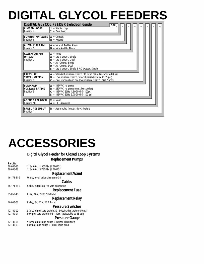
DGF_ _ _ _ _ _ _ _CLOSED LOOPS 1 = Single LoopPosition 4 2 = Dual Loop
CONDUIT / PREWIRE A = ConduitPosition 5 B = Prewire
AUDIBLE ALARM A = without Audible AlarmPosition 6 B = with Audible Alarm
ALARM OUTPUT X = NoneOPTION A = Dry Contact, SinglePosition 7 B = Dry Contact, Dual
C = AC Output, SingleD = AC Output, DualE = Dry Contact, Single & AC Output, Single
PRESSURE A = Standard pressure switch, 30 to 50 psi (adjustable to 80 psi)SWITCH OPTION B = Low pressure switch, 5 to 10 psi (adjustable to 35 psi)Position 8 C = One standard and one low pressure switch (DGF2 only)
PUMP AND A = 115VAC no pumpVOLTAGE RATING B = 230VAC no pump (must be conduit)Position 9 C = 115VAC 60Hz 1.50GPM @ 100psi
E = 115VAC 60Hz 3.75GPM @ 100 psi
AGENCY APPROVAL X = NonePosition 10 A = ETL Approval
PANEL ASSEMBLY B = Assembled (must ship via freight)Position 11
DIGITAL GLYCOL FEEDER Selection Guide
Digital Glycol Feeder for Closed Loop Systems
Part No. 18-600-35 115V 60Hz 1.50GPM @ 100PSI18-600-42 115V 60Hz 3.75GPM @ 100PSI
16-171-81-9 Wand, level, adjustable up to 34
16-171-81-3 Cable, extension, 10' with connectors
05-052-18 Fuse, 16A, 250V, 5X20MM
10-006-01 Relay, 5V, 12A, PCB Type
12-140-00 Standard pressure switch 30 - 50psi (adjustable to 80 psi)12-140-01 Low pressure switch to 5 - 10psi (adjustable to 35 psi)
12-130-01 Standard pressure gauge 0-100psi, liquid filled12-130-03 Low pressure gauge 0-30psi, liquid filled
Pressure Gauge
Replacement Pumps
Replacement Wand
Cables
Replacement Fuse
Replacement Relay
Pressure Switches

33
FLOW CONTROLLERS
CORROSION COUPON RACKS
Model No. FC2000 Flow Controller
Standard flow controller has 3/4 PVC threaded connections with 3/4" PVCslip adaptors to use if needed. 1 GPM minimum flow required for activation
FC2000C Flow ControllerStandard flow controller w/ 1 PVC slip connectors; 1 GPM min. flow required for activation.
Available options for FC2000 & FC2000C: Receptacle functions (Standard--both on with flow) 1 Both on with no flow2 One on with flow, other on no flow3 One on with flow, other service4 One on with no flow, other service
Replacement Flow Assemblies 16-977-79 3/4 (FC2000)16-977-71 1 (FC2000C)
Flow Controllers
Model No. CCR1 1 station ........................................................................................................ CCR2 2 stations ...................................................................................................... CCR3 3 stations ...................................................................................................... CCR4 4 stations ...................................................................................................... CCR5 5 stations ...................................................................................................... CCR6 6 stations ......................................................................................................
CCR1A CCR1B CCR1C CCR1DCCR2A CCR2B CCR2C CCR2DCCR3A CCR3B CCR3C CCR3D CCR4A CCR4B CCR4C CCR4D CCR5A CCR5B CCR5C CCR5DCCR6A CCR6B CCR6C CCR6D
Available options: X1 Quick release coupon holders (PVC only)X4 3/4 hot/cold water flow meterX6 1 cold water flow meter X7 PVC outlet ball valve std, 3/4 blk iron units use 3/4" brass gate valve 250 psiX8A Y Strainer for 3/4 PVCX8B Y Strainer for 1 PVC or CPVCX8C Y Strainer for 3/4 CPVC or black iron X9 Clear PVC pipe sectionsU1 Mounting strut - Black Iron only (no panel)F3 Flow control valve 3 GPM (3/4" only)F5 Flow control valve 5 GPM (3/4" only)
Part No. 16-756-51-1 Quick Release coupon holder with hardware16-756-50 PVC and CPVC holder with hardware16-756-42 Steel on black iron holder with hardware33-022-16 3/4 hot/cold water flow meter
NOTE: Options X4 and X6 for max. 150 psi (10.4 bar) @ 130ºF (54ºC).
Coupon Rack Replacement Parts
Corrosion Coupon Racks Standard system includes: PVC coupon holder, nylon screw and nut, PVC inlet ball valve, 0.75 in. (19mm)piping, and Schedule 80 PVC mounted on 0.50 in. HDPE. System does not include coupons (see page 33).
Available optional Piping: 1" PVC piping 3/4" CPVC piping 1" CPVC piping 3/4" black iron piping

CORROSION DEPOSIT MONITOR Model No.
DPM14 DPM24 (230 VAC wiring)
Part No.03-220-10 Mild Steel03-220-00 Copper03-220-60 303 Stainless Ste03-220-70 304 Stainless Steel03-220-20 316 Stainless Steel03-220-50 Nickel 03-221-30 Brass03-221-40 Bronze03-221-50 Aluminum
03-008-00 Small Neoprene O-rings (2 required)03-210-06 Compression fittings for end blocks (2 per block)03-013-00 Large Neoprene O-rings (2 required) 05-047-50 Sight glass (1 required)05-052-00 15 amp fuse (1 required) 05-051-00 Fuse holder for 05-052-0005-047-20 Heater cartridge (1 required)05-047-30 Left exchanger end block (1 required) 05-047-40 Right exchanger end block (1 required)05-047-35 Center exchanger block (1 required)
03-223-00 Mild Steel03-223-10 Copper03-223-30 304 Stainless Steel03-223-40 316 Stainless Steel
03-223-50 Nickel
03-223-60 Brass
J61135 3/4" corporation stop - PVC 120 psi
10-014-03 AC Power and Telecom surge/spike protector (115V)
12-066-00 Sample Cooler
Surge Protector
Sample Coolers
Corrosion Deposit Monitor
Self contained systems for monitoring corrosion and deposition characteristics of cooling water sy
Coupons for Corrosion Coupon Racks & Corrosion Deposit Monitors
Corrosion Deposit Monitor Replacement Parts
Specimen Tubes for Corrosion Deposit Monitor
Corporation Stops
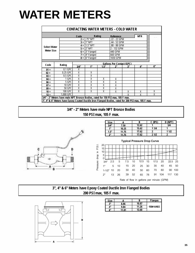
35
WATER METERS Code Reference MTR _ _ _
3/4" 1" 1.5" 2" 3" 4" 01 = X02 = X X 03 = X X 04 = X X X X 06 = X X X X 07 = X X X X 09 = X X X X 10 = X X X X X X 13 = X X
CONTACTING WATER METERS - COLD WATER
Rating
Select Water Meter Size
2 = .75" NPT .22 - 22 GPM3 = 1" NPT .44 - 52 GPM4 = 1.5" NPT .88 - 88 GPM5 = 2" NPT 2 - 132 GPM6 = 3" Flanged 440 GPM7 = 4" Flanged 660 GPM8 = 6" Flanged 1650 GPM
Code Rating Gallons Per Contact (GPC)6"
0.1 GPC0.25 GPC 0.5 GPC
1 GPC 5 GPC
10 GPC 50 GPC
100 GPC X 1,000 GPC X
3/4" - 2" Meters have male NPT Bronze Bodies, rated for 150 PSI max, 105 F max.3", 4" & 6" Meters have Epoxy Coated Ductile Iron Flanged Bodies, rated for 200 PSI max, 105 F max.
Size A3/4" 7.501" 10.25
1.5" 11.752" 11.75
Size A3" 8.864" 9.846" 11.81
10.87
3/412.62 1
11.26 150# ANSI13.60
3/4" - 2" Meters have male NPT Bronze Bodies150 PSI max, 105 F max.
3", 4" & 6" Meters have Epoxy Coated Ductile Iron Flanged Bodies200 PSI max, 105 F max.
11 1/2217.62
1 1/422 1/2
15.6217.62
B C (IPS) D (NPT)
FlangesB

VALVES-COOLING APPLICATIONS
Part No.Zero psi differential, 105 psi max. 115 VAC, brass bodies, buna seals, NC, 176ºF, 2 way SVC-0.50-115-ODPSVC-0.75-115-ODP
1.5 psi differential, 150 psi max. 115 psi max. 115 VAC, brass bodies, buna seals, NC, 176ºF, 2 waySVC-0.50-115SVC-0.75-115
3 psi differential, 225 psi max. 115 psi max. 115 VAC, brass bodies, buna seals, NC, 176ºF, 2 waySVC-1.00-115SVC-1.50-115SVC-2.00-115
Solenoid Valves
SVC Series
Part No. Motorized Valves for Cooling Tower Applications Low differential pressure applications. Brass bodies. 12-045-00 1/2" NPT (25 psi maximum)12-054-10 3/4" NPT (25 psi maximum)12-057-00 1" NPT (15 psi maximum)
Motorized Valves for Cooling Tower Applications. Brass valve, full port, with electric actuator. 12-054-14 1/2" NPT 12-054-13 3/4" NPT 12-054-12 1" NPT12-054-11 2" NPT
Includes SVC solenoid valve, steel Y-strainer, and brass shutoff valve. 16-900-18 3/4" 16-900-12 1"16-900-13 1 1/2" 16-900-14 2"16-900-18-1 16-900-18 less solenoid valve16-900-12-1 16-900-12 less solenoid valve16-900-13-1 16-900-13 less solenoid valve16-900-14-1 16-900-14 less solenoid valve
26-034-48-1 Complete sample stream assembly. Includes: flow switch, PVC shutoff valve (input side), bowl strainer, sample valve, PVC shutoff valve (output side)
26-034-48-2 Same as above less flow switch03-034-00 3/4" Tee TXTXT, PVC03-174-00 Reducer Bushing, 3/4S x 1/2T, PVC03-048-11 3/4" Tee TXTXT, CPVC12-068-00 1" Steel Y-strainer 12-071-00 3/4" Steel Y-strainer12-069-00 3/4" Clear PVC Y-strainer12-070-00 Replacement mesh for 12-069-00 12-072-11 1" PVC shutoff valve12-079-00 1" Brass shutoff valve 12-072-00 3/4" PVC ball valve 16-810-00 2 stage injection manifold 16-810-03 3 stage injection manifold 16-810-04 4 stage injection manifold16-810-08 5 stage injection manifold04-300-08 Sample valve assembly
EC Series - Motorized Valves
Dynamatic Series - Motorized Valves
Bleed-off Piping Assembly
Sample Stream Parts
37
VALVES-BOILER APPLICATIONS Part No.16-896-00 Up to 100 psi
Package includes 1/2" solenoid valve (12-048-00) and 1" orificeunion with 4 orifice plates (12-012-00 and 12-013-50).
16-896-04 Up to 300 psiPackage includes 1/2" motorized ball valve with heavy duty 90 degree actuator (16-892-00) and 1/2" flow throttling valve (12-046-01).
16-896-08 Up to 450 psi Package includes 1/2" motorized ball valve with 360 degree actuator (16-892-02) and 1" orifice union with 4 orifice plates (12-012-00 and 12-013-50).
16-896-02 Up to 100 psiPackage includes 3/4" solenoid valve (12-056-00) and two 1" orificeunions with 4 orifice plates each (12-012-00 and 12-013-50).
16-896-06 Up to 300 psiPackage includes 3/4 motorized ball valve with 90 degree actuator (16-892-01), 3/4 flow throttling valve (12-055-01), and 1/2" flow throttlingvalve (12-046-01).
16-896-10 Up to 425 psiPackage includes 3/4" motorized ball valve with 360 degree actuator (16-892-04) and two 1" orifice unions with 4 orifice plates each (12-012-00 and 12-013-50).
Available option: -2 230 VAC service
Note: $65.40 adder is only for models 16-896-04, -06, -08 and -10.
NOTE: Materials of construction: Solenoid Valves are bronze body with stainless steel pilot and valves; Motorized Ball Valves are carbon steel body with 316 stainless steel ball and stem; Throttling Valves are carbon steel body and valve; and Orfice Unions are carbon steel union with stainless steel plates.
12-052-02 1" motorized 3-way valve 16-896-16* 1-1/2" motorized 3-way valve 16-896-18* 2" motorized 3-way valve
*Consult factory for lead time.
0 psi differential, 100 psi, 115 VAC, brass bodies, PTFE, NC, 2 way 12-048-00 1/2"12-056-00 3/4"
Valve Packages (For Use with Times Sample Systems
Valve Packages (For Use with Continuous Sample Systems)
Diverter Valves
Solenoid Valves - SVB Series

VALVES-BOILER APPLICATIONS Part No.16-892-00 1/2" motorized ball valve (10-75 Worcester Actuator) 16-892-01 3/4" motorized ball valve (10-75 Worcester Actuator)16-892-02 1/2" motorized ball valve (10-36 Worcester Actuator) 16-892-04 3/4" motorized ball valve (10-36 Worcester Actuator)16-892-16 1/2" high steam rated motorized ball valve (10-36 Worcester Actuator)16-892-18 3/4" high steam rated motorized ball valve (12-75 Worcester Actuator)
Available option: -2 230 VAC service
12-040-00 Worcester 10-75 actuator only 12-040-10 Worcester 10-36 actuator only
12-043-00 Worcester 1/2" steam rated ball valve only12-051-00 Worcester 3/4" steam rated ball valve only12-041-00 Mounting kit for 12-043-00 & 12-040-0012-041-10 Mounting kit for 12-043-00 & 12-040-10 12-049-00 Mounting kit for 12-051-00 & 12-040-00 12-049-10 Mounting kit for 12-051-00 & 12-040-10 05-006-20 Limit switch for 10-36 actuator
12-075-01 3/8" valve (300 psi maximum)12-046-01 1/2" valve (300 psi maximum)12-055-01 3/4" valve (300 psi maximum)12-012-00-1 1" orifice union with set of (4) orifice plates12-013-50 Set of four orifice plates
Motorized Ball Valves
Motorized Ball Valve Parts
Flow Control Valves

39
CONDUCTIVITY TESTERS Model No.
HJ6BC 0-100, 0-1000, 0-10,000 µS/cm HJ7B 0-50, 0-500, 0-5,000 µS/cm
Part No.
20-016-24 500 conductivity (6 pack)20-016-26 2000 conductivity (6 pack) 20-016-28 5000 conductivity (6 pack) 20-016-00 500 conductivity (1 bottle)20-016-02 2000 conductivity (1 bottle)20-016-04 5000 conductivity (1 bottle)
20-016-36 pH 4 buffer solution - 4 oz 20-016-37 pH 4 buffer solution - 32 oz20-016-38 pH 7 buffer solution - 4 oz20-016-39 pH 7 buffer solution - 32 oz20-016-40 pH 10 buffer solution - 4 oz20-016-41 pH 10 buffer solution - 32 oz
20-016-42 ORP 100 mV buffer solution - 4 oz20-016-43 ORP 100 mV buffer solution - 32 oz20-016-44 ORP 465 mV buffer solution - 4 oz20-016-45 ORP 465 mV buffer solution - 32 oz
Hand Held Conductivity Testers
Calibration Solutions
Conductivity Solutions (500 ml bottles)
pH Kit Solutions
ORP Kit Solutions
ACT / ABC PARTS Part No.08-986-05 Power supply board assembly, ETL/CE
08-986-06 Limit timer board assembly
15-920-08 Panel assembly ACT102BC15-920-08-1 "CE" Panel assembly ACT102ABCPV1 15-920-12 Panel assembly ACT102B 15-920-12-1 "CE" Panel assembly ACT102ABPV1 15-920-20 Panel assembly ACT102 15-920-20-1 "CE" Panel assembly ACT102APV1
15-920-28 Panel assembly ABC102 15-920-28-1 "CE" Panel assembly ABC102P5V1
16-596-20 Flow assembly, with flow switch conductivity (no sensor)
03-093-00 Male adaptor, 3/4" 03-096-62-E Elbow tee, 3/4"04-300-08 Sample valve assembly03-096-56-E Tee, sensor03-096-52-E Tee, flow, clear03-005-05 O-ring, 1 1/2" ID, 1 3/4" OD, 1/16" Thk (tee)03-005-04-2 O-ring, 15/16" ID, 1 1/8" OD, 3/32" Thk (sensor/ sensor holder)06-008-00-E Coupling Nut03-096-71-E Pipe Nipple, 3/4" x 3.00 long04-300-90-1 Flow Switch04-300-91 "CE" flow switch
ACT / ABC Parts (101/102 only)
ACT Parts (101/102 onl)
ACT Motherboard Panel Assemblies, Complete
ABC Mother Board Panel Assemblies, Complete
ACT Flow Assemblies, Complete
ACT Flow Assembly Components
41
CONTROLLER PARTS Part No. Description Applicable Series
08-985-05 Conductivity card 10008-985-50 Isolated pH card 10008-600-48 Serial line comm. card w/o 2400 baud modem 200/300/920008-600-45 Serial line comm. card w/ 2400 baud modem 200/300/920008-600-06 Dual conductivity card All Series except 10008-600-16 Single conductivity card All Series except 10008-600-08 Dual pH/ORP card All Series except 10008-600-18 Single pH card All Series except 10008-600-23 Dual conductivity card for boilers and hi-pressure All Series except 10008-600-21 Single conductivity card for boilers and hi-pressure All Series except 10008-600-12 Dual 4-20mA output card All Series except 10008-600-13 Single 4-20mA output card 200/300/920008-600-10-1 Dual 4-20mA input card 9600/950008-600-19 Single ORP card 9300/9500/960008-600-48 Serial line comm. card w/o 14.4K baud modem 9300/9500/960108-600-59 Serial line comm. card w/ 14.4K baud modem 9300/9500/9602
08-985-00-E Mother board, 100 Series 10012-042-73 Kit, 100 Series mother board w/ battery 10012-042-74 Kit, 100 Series mother board w/ M1 option 10012-042-75 Kit, 100 Series mother board w/ M2, M3 option 10008-600-14-2 Mother board with 2 line display 200/920008-600-50 Mother board for 2 line display 200/920008-600-15-2 Mother board with 8 line display 300/9300/9500/960008-600-52 Mother board for 8 line display 300/9300/9500/9601
12-042-76 Power supply/relay board w/ K option 10008-985-60 Power supply/relay board w/o connectors 10008-600-04-1 Relay board w/o dry contact option, 200 Series 20008-600-04-2 Relay board w/o dry contact option, 200 Series 200/920008-600-05-1 Relay board w/o dry contact option, 200 Series 30008-600-03-3 Relay board w/o dry contact option, 200 Series All Series except 10008-600-47-2 Relay board w/o dry contact option, 200 Series All Series except 10008-600-65-3 Relay board w/o dry contact option, 200 Series 400/9300/9500/9600
12-042-71 Kit, Power supply/relay board complete 10012-042-77 Kit, Relay board complete 200/920012-042-72 Kit, power supply board w/ cables to relay board 200/300/920012-042-78 Kit, Relay board complete 30012-042-79 Kit, CE" power supply board complete All Series except 10012-042-83 Kit, Relay board complete 9300/9500/9600
10-001-08-E Relay, AC/IO, module, plug-in/screw mounting 200/300/920010-001-12 Relay, SPDT, 10A, 12VDC coil, mech., plug-in All Series except 100
Daughter Cards
Mother Boards
Power Supply / Relay Boards
Kits, Power Supply / Relay Boards
Relays

CONTROLLER PARTS Part No. Description Applicable Series
12-042-61 Kit, fuse, 1A, 250V, rectangular (pkg. of 5) 10012-450-01 Kit, fuses (1A, 125V and 5A, 125V) and jumpers 10012-450-04 Kit, fuses (5A 250V slo-blo) and jumpers 10012-042-62 Kit, fuse, 5A, 125V, rectangular (pkg. of 5) 200/300/920012-042-62-1 Kit, fuse, 5A, 250V, round (pkg. of 5) 200/300/920012-450-00 Kit, fuses (1A, 250V and 5A, 250V) and jumpers 200/300/920012-450-02 Kit, fuses, (1/4A, 250V and 5A, 125V) and jumpers 300/9300/9500/960012-042-62-2 Kit, fuse, 5A, 250V, slo-blo, round (pkg. of 5) All Series except 100 12-042-85 Kit, fuse, 1A, 250V, slo-blo, glass (pkg. of 5) All Series except 100 12-450-03 Kit, fuses (1A & 5A, 250V, slo-blo) and jumpers All Series except 100 12-450-05 Kit, CE" fuses (1.6A & 5A, 250V slo-blo) and jumpers All Series except 100 12-450-06 Kit, fuse, 63mA, 250V, slo-blo (pkg. of 4) 9300/9500/9600
Standard Flow Assemblies 16-596-00 Flow assembly, with flow switch (no sensor)16-596-02 Flow assembly, with flow switch for pH or ORP (no sensor)16-596-04 Flow assembly, with flow switch for pH/ORP (no sensors) 16-596-08 Flow assembly, with flow switch for pH/ORP/Cond (no sensors)16-596-12 Flow assembly, with flow switch for pH/Cond or ORP/Cond (no sensors)16-596-22 Flow assembly, with flow switch for conductivity (no sensor)
Hi-Pressure Flow Assemblies 16-596-24 Flow assembly, w/o flow switch for conductivity (no sensor) "B1"16-596-26 Flow assembly, w/o flow switch for pH (no sensor) "B2" 16-596-28 Flow assembly, w/o flow switch for pH/Cond or ORP/Cond (no sensors) "B3"16-596-30 Flow assembly, w/o flow switch for ORP (no sensor) "B4"16-596-32 Flow assembly, w/o flow switch for pH/ORP (no sensors) "B6"16-596-34 Flow assembly, w/o flow switch for pH/ORP/Cond (no sensors) "B7"
"CE" Flow Assemblies (R1)16-596-01 Flow assembly, with flow switch (no sensor)16-596-03 Flow assembly, with flow switch for pH or ORP (no sensors) 16-596-05 Flow assembly, with flow switch for pH/ORP (no sensors)16-596-09 Flow assembly, with flow switch for pH/ORP/Cond (no sensors)16-596-13 Flow assembly, with flow switch for pH/Cond or ORP/Cond (no sensors)16-596-23-1 Flow assembly, with flow switch for conductivity (no sensor)
Kits, Fuse / Spare Parts
Complete Flow Assemblies
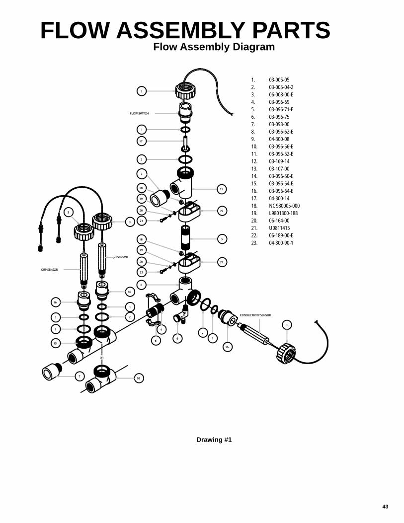
43
Flow Assembly Diagram FLOW ASSEMBLY PARTS
Drawing #1
1. 03-005-052. 03-005-04-23. 06-008-00-E 4. 03-096-69 5. 03-096-71-E6. 03-096-75 7. 03-093-008. 03-096-62-E9. 04-300-0810. 03-096-56-E11. 03-096-52-E12. 03-169-1413. 03-107-0014. 03-096-50-E 15. 03-096-54-E16. 03-096-64-E 17. 04-300-1418. NC980005-000 19. L9801300-18820. 06-164-0021. U081141522. 06-189-00-E23. 04-300-90-1
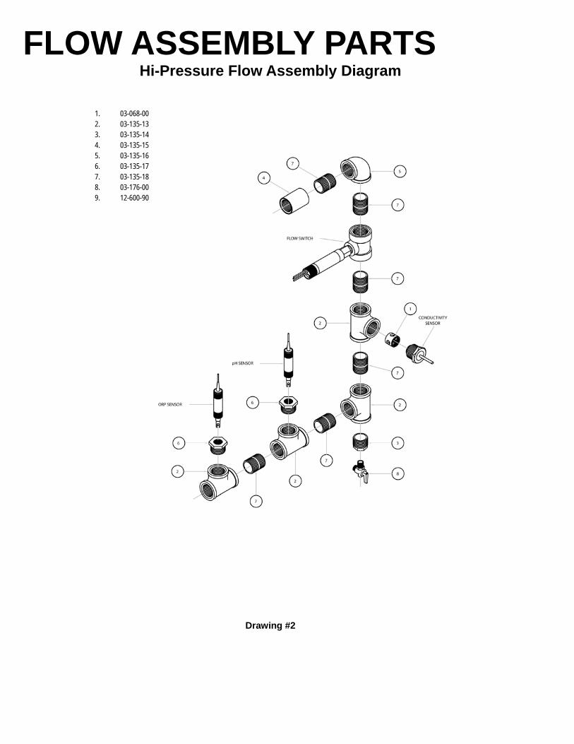
FLOW ASSEMBLY PARTS Hi-Pressure Flow Assembly Diagram
Drawing #2
1. 03-068-002. 03-135-133. 03-135-14 4. 03-135-155. 03-135-166. 03-135-177. 03-135-188. 03-176-00 9. 12-600-90

45
Policies and Procedures
1. Manufacturer’s Equipment Warranty
a. Pulsafeeder warrants all pumps and controllers of its manufacture to be free of defects in material or workmanship. Liability un-der this policy extends for 24 months from date of shipment from the factory. The manufacturer’s liability is limited to repair or replacement of any failed equipment or part which is proven defective in material or workmanship upon manufacturer’s examina-tion. This warranty does not include removal or installation costs and in no event shall the manufacturer’s liability exceed the selling price of such equipment or part.
b. The manufacturer disclaims all liability for damage to its products through improper installation, maintenance, use or attempts to operate such products beyond their functional capacity, intentionally or otherwise, or any other unauthorized repair. The manu-facturer is not responsible for consequential or other damages, injuries or expense incurred through the use of its products.
c. The above warranty is in lieu of any other warranty, whether expressed or implied. The manufacturer makes no warranty of fitness or merchantability. No agent of ours is authorized to provide any warranty other than the above.
2. Pulsafeeder’s Parts and Accessory Warranty a. Pulsafeeder, Inc. warrants parts and accessories provided to be free of defects in material or workmanship. Unless otherwise
noted below, liability under this policy extends for 90 days from date of shipment from the factory when sold as service parts. (Replaceable elastomeric parts are expendable and are not covered by any warranty either expressed or implied.)
b. This policy is extended to a full 12 months from the date of installation or 18 months from shipment from the factory whichever comes first on the following accessories; Intelliscan Digital Glycol Feeders Analog Timers Water Meters Flow Controllers
c. MicroTrac and MicroVision toroidal probes are warranted for 24 months from date of shipment from the factory when purchased in conjunction with the controller. All other electrodes/probes and sensors are considered maintenance items and such are warranted for six (6) months from the
date of shipment when purchased in conjunction with the controller. Any electrodes/probes and sensors purchased as spare parts are warranted for 90 days from date of shipment.
d. The manufacturer’s liability is limited to repair or replacement of any failed equipment or part which is proven defective in mate-rial or workmanship upon manufacturer’s examination. This warranty does not include removal or installation costs and in no event shall the manufacturer’s liability exceed the selling price of such equipment or part.
e. The manufacturer disclaims all liability for damages to its products through improper installation, maintenance, use or attempts to operate such products beyond their functional capacity, intentionally or otherwise, or any unauthorized repair. The manufac-turer is not responsible for consequential or other damages, injuries or expense incurred through the use of its products.
f. The above warranty is in lieu of any other warranty, whether expressed or implied. The manufacturer makes no warranty of fitness or merchantability. No agent of ours is authorized to provide any warranty other than the above.
3. Process for All Returned Goods a. Please contact our Customer Service Department to request a RMA (Return Material Authorization) number prior to returning
any goods. The following information will be required: Billing and ship-to address Model number and serial number Contact name and phone number Reason for return Purchase order (where applicable) A packing slip will be provided to the shipper and MUST accompany the product being returned. Packages received without our
proper packing list will be refused by the receiver. b. All material must be returned freight prepaid. c. All material must be properly packaged to prevent damage in shipment. d. All products MUST be wiped and flushed clean of any and all chemicals, solvents or buffers and be warranted to be safe for
handling. You will be requested to acknowledge the condition of the product being returned on our packing list. Any product received that is deemed to be unsafe for handling or without this acknowledgement will be refused by our receiver.
e. RMA for returning product for credit is effective for 90 days from the date of issue. After 90 days if the product has not been returned to Pulsafeeder the RMA number will be cancelled, and a new request must be made by the customer to continue with the return procedure.
4. Non-Warranty Return Procedure a. If you are experiencing a concern with your Pulsafeeder product, first consult the distributor, dealer or Regional Sales Manager
or the operation and maintenance manual for assistance. If service of your non-warranty unit is necessary, you must request a return material authorization. A RMA form will be issued and must be used as the packing list attached to the outside of the box. Please send the unit freight prepaid with the RMA number visibly displayed on the outside of the carton. All products MUST be wiped and flushed clean of any and all chemicals, solvents or buffers and be warranted to be safe for handling. You will be re-quested to acknowledge the condition of the product being returned on our packing list. Any product received that is deemed to be unsafe for handling or without this acknowledgement will be refused by our receiver.
b. The charges listed in the following table will apply.
c. Extended warranty on repair goods will be offered only when the repairs were made by the factory on non-warranty units. i. Microprocessor Controls – 1 year from date of shipment ii. Electronic Controls – 6 months from date of shipment (excluding electronic parts) iii. Standard metering pumps – 3 months from date of shipment
Product Repair Cost
Pumps and Pump Accessories – within 5 years of sale date Current List Price x .50 x Part Discount Multiplier
Controllers and Controller Accessories within 5 years of sale date Current List Price x .50 x Part Discount Multiplier
Any item older than 5 years from date of sale With purchase order, $50 bench fee to evaluate. The $50 bench fee may be ap-plied towards repair cost of unit or towards a new controller

5. Credit for Return of New, Unused Equipment a. No equipment will be accepted beyond six months after date of shipment from factory for credit. b. Only new, unused and undamaged standard equipment will be accepted for return to stock. c. All credits are based on evaluation and acceptance of material as new and unused by Pulsafeeder. You will be requested to
acknowledge the condition of the product being returned on our packing list. Any product received that is deemed to be unsafe for handling or without this acknowledgement will be refused by our receiver.
d. A restocking fee of 25% will apply to returned goods. When a PO is provided for a replacement item at the time of the return request the restocking fee will be 15%. Note: any product mounted on a panel or skid will be charged a 50% re-stocking fee.
e. A request for a Returned Material Authorization (RMA) number must be made prior to returning product to Pulsafeeder. f. All equipment shall be returned with the RMA Packing List form attached to the outside of the box. g. If any chemical, solvent or buffer has been introduced into the product it must be wiped and flushed clean of any and all sub-
stances prior to returning to Pulsafeeder. h. All material shall be returned freight prepaid. i. Private label products or Engineered Panel Mount Systems are not returnable.
6. Pricing Errors
a. Pulsafeeder does their very best to avoid errors in billing. You will receive a confirmation of your order within 24 hours of order entry. If upon review the customer feels there is a discrepancy, they should contact Pulsafeeder Customer Service as soon as possible to resolve.
b. Should an invoice be received that the customer believes to have incorrect pricing, they should notify Pulsafeeder Customer Service to investigate.
7. Missing Items a. If a product is received by the customer with an item missing the customer must notify Pulsafeeder Customer Service within 7
days of receipt of the product by the end user. A replacement item will be sent at no charge as quickly as possible. b. If a shipment is received by the customer with a line item missing they must notify Pulsafeeder Customer Service within 7 days
of receipt of the product by the end user. If the customer had been billed for that item, a credit will be issued against the original Sales Order and a new Sales Order will be created for the replacement product.
8. Damaged Items a. Should the customer receive an order that was damaged in transit, the customer must notify the carrier directly to initiate a claim
on the day of delivery. b. Should the customer receive a product with damaged components due to improper packaging they should notify Pulsafeeder
Customer Service within 7 days of receipt of product by end user. A replacement item will be sent at no charge as quickly as possible.
9. Technical Support Services Available a. Pulsafeeder’s Technical Sales Support team is available to provide all your sales and support needs. The principle mission of
this group is to sell and support our customer base in a timely and effective manner. This includes the ability to provide in-field service training, assistance in start-up of our products and perform field repair of goods when required.
b. Scope Pulsafeeder, Inc. factory Field Service Technicians are available throughout the World for field services on all Pulsafeeder prod-ucts. Services include: i. Maintenance Training Seminars, including Classroom slide presentations and or Hands-on Training. The seminar will
take approximately four to five hours, and if time permits minor repair and or adjustments may be made to the cus-tomer’s pumps, controllers or accessories.
ii. Pre-start up inspections and start up testing/calibration of pumps, controllers and accessories. iii. Field repairs of pumps controllers and accessories
iv. Diagnosing and recommending solutions to systems problems.
(1) All rates listed in this section are actual hourly and daily rates, not reference rates.
Fee Schedule Field Repairs and Start-ups
Service Rate (1)
Normal 8 hour day $98.00/hour Overtime (in excess of 8 hrs, each day) $148.00/hour
Sundays, National Holiday $195.00/hour Travel time to job site and return $87.00/hour Travel expenses (air fare, hotel, car and meals) Chargeable to customer at cost Minimum charge 4 hours labor, plus travel time and expenses
End User Training Seminars Normal work day $750.00/day plus expenses (air fare, car rental, hotel and meals at cost) Sundays, National Holiday $1495.00/day plus expenses (air fare, car rental, hotel and meals at cost)

47
TERMS & CONDITIONS 1 . AGREEMENT. The contract of sale resulting from Seller’s documentation together with these terms and conditions (“Contract”) constitutes the entire agreement between the parties hereto, except as modified in writing signed by both the Seller and Purchaser. The Seller is Pulsafeeder, Inc. and the Purchaser is identified in the Contract. Any terms in a purchase order, irrespective of their materiality, which are either different from or additional to Seller’s conditions of sale, are objected to and are excluded unless the Seller expressly agrees in writing to such terms. Execution of such forms by Seller to accommodate Purchaser’s procurement or accounting procedures or to evidence agreed up on change orders shall not be construed as assent to Purchaser’s terms. Acceptance of the goods shipped shall constitute assent to Seller’s conditions of sale. This Contract shall be binding up on Purchaser and Seller, and on their successors and assigns. 2 . PROPOSAL OR QUOTATION. A proposal shall not become binding up on Seller until it has been executed and returned by Purchaser. An oral quotation shall not be considered an offer: only a written confirmation thereof incorporating Seller’s terms and conditions shall constitute an offer. 3 . CREDIT. Credit terms of payment must have the approval of Seller’s Credit Department and must be specified in writing on Seller’s invoice or in the Contract. If Purchaser’s credit is found by Seller to be unsatisfactory . Seller may rescind or terminate this Contract. If at any time during the term of this Contract Purchaser’s financial responsibility becomes impaired or unsatisfactory to Seller, Seller reserves the right to stop shipment on notification to Purchaser, project owner and surety with a demand for payment in advance or at time of delivery for future deliveries or to require other security satisfactory to Seller and in the absence thereof, to cancel the unfilled portion of the Contract. Seller will notify Purchaser promptly of its decision to stop shipments and give an advance notice to the extent this is possible. In the absence of credit terms, sales are for cash. 4 . PAYMENT. Specific terms of payment for this order shall be set forth on the reverse side of this Contract or identified and appended hereto. Purchaser agrees to make payment at Seller’s location specified in this Contract in lawful money of the United States. Purchaser further agrees to make all payments when due to Seller in accordance with the agreed terms of payment in this Contract without reference to Purchaser’s agreement with or payments by the owner and with no right of retention. 5 . INTEREST AND COSTS. Purchaser agrees to pay interest at 1.5% per month (to the extent permitted by law) on all delinquent balances if and when assessed by Seller, and any attorney’s fees or court costs arising out of and made necessary in collection of its obligation to Seller created by this Contract. 6 . TAXES. Any federal, state or local tax assessment, fee, duty or charge hereafter imposed on or measured by the products purchased hereunder shall be for Purchaser’s account unless Purchaser furnishes Seller an acceptable exemption certificate from such tax, fee, duty or charge prior to shipment. 7 . FORCE MAJEURE. Seller shall make delivery in accordance with the terms of this Contract or within a reasonable time in the absence of any commitment, but Seller shall not be liable for delays or defaults in delivery caused by floods, fires, storms, or other acts of God, by war or act of public enemy (or civil disturbance), strikes, lock outs, shortages of labor or raw materials and supplies (including fuel) or production facilities, transportation service or equipment shortages or failures, action of any governmental authority or other conditions beyond Seller’s reasonable control. 8 . CANCELLATION. If Purchaser desires to cancel or change any portion of this Contract, he must make such request in writing to Seller. Seller may, in its sole discretion, accept or reject any such request. If accepted, the Purchaser nonetheless must take delivery and make payment to Seller for all material manufactured and in process of manufacture at time of notice, and all special materials ordered at time of notice and for which Seller must take delivery , unless otherwise agreed by Seller in writing. All such materials must be removed from Seller’s premises within 30 days after payment and payment will due at time of notice. Seller also reserves the right to make a cancellation charge in the event of cancellation by the Purchaser of an order p laced in Seller’s shipping schedule and acknowledged by Seller. 9 . INSPECTION AND TESTING . Seller’s standard specifications and tests apply to all orders. All charges for inspections or tests not regularly furnished are for Purchaser’s account and subject to prior negotiation. All inspections shall be conducted at Seller’s plant, and failure of Purchaser to avail himself of inspection privileges shall be deemed a waiver of such privileges. 1 0 . PRICES. Prices are subject to change without notice. Orders based on published prices and accepted for scheduled shipment will be invoiced at Seller’s applicable price in effect on the scheduled date of shipment, unless otherwise specifically noted on the order acknowledgment. All prices will be in accordance with applicable government regulations. Orders specifying palletizing or special packaging will involve special charges. 1 1 . DELAYS. All orders are accepted subject to Seller’s ability to make delivery at the time and in the quantities specified, and Seller shall not be liable for damages for failure to make partial or complete shipment or for any delay in making shipments. Purchaser shall be liable for any added expenses incurred by Seller because of Purchaser’s delay in fur-nishing requested information to Seller, delay resulting from order changes by Purchaser, or delay in unloading shipments at delivery point. 1 2 . SHIPMENT. Seller will select method of shipment and routing when transportation charges are for account of Seller. When shipping instructions are specified by the Purchaser, all costs will be for the account of the Purchaser. The foregoing includes, but is not limited to, carriers charges for notification prior to delivery, demurrage, delay in unloading, diver-sion, or reconsignment. 1 3 . TITLE. Title to products transfers up on delivery to Purchaser at the F.O.B. point of delivery which will be clearly set forth in the shipment terms of this Contract. On receipt of title, Purchaser is then responsible for proper protection of product, placement, compliance with all regulations and ordinances, and will indemnify Seller against all claims for per-sonal injuries or property damage arising from the storage, use or handling of such products. 1 4 . IN TRANSIT CLAIMS. Claims for damage or shortage in transit must be made against the carrier by the owner of the shipment according to the F.O.B. terms of the Contract. Purchaser has the responsibility to inspect shipments before or during unloading to identify any such damage or shortage and see that appropriate notation is made on the delivery tickets or an inspection report furnished by the local agent of the carrier in order to support a claim. 1 5 . CLAIMS. Notice of Claims against Seller hereunder for any reason, must be made to Seller in writing promptly after discovery and within any applicable warranty period. Failure to give such notice to Seller shall constitute a waiver by Purchaser of any right later to assert such a claim. 1 6 . RETURNS. Returned goods shall be accepted for credit only if in salable condition and only with evidence of Seller’s prior written consent. Seller will assess charges for freight both ways and any costs necessary to restore such goods to the regular plant inventory . The amount of credit given will depend further up on the degree of salability of products accepted in opinion of Seller. 1 7 . PATENTS. Seller agrees to defend, and to protect Purchaser against loss or damage arising out of any legal action for patent infringement in connection with the manufacture of its products sold to Purchaser, provided Seller is notified promptly of any such action with complete information and is given an opportunity to defend. 1 8 . WARRANTY : LIMITATION OF LIAB ILITY . Seller warrants title to each individual product sold under this Contract and further warrants for a period of eighteen (18 ) months from ship date or one (1 ) year from date of installation, whichever comes first, but only to the extent and limit of the purchase price paid for such individual product, that such product conforms to the specifications set forth in the Contract and is free from defects in material and workmanship under normal service and use for which it was designed. Seller’s sole obligation and Purchaser’s exclusive remedy under this warranty shall be limited to one of the following, as selected by Seller: delivering to Purchaser a replacement for any product or part thereof determined by Seller to be defective, repairing such product or part, or refunding the purchase price (or an equitable portion thereof) paid for such product or part by Purchaser. SELLER MAKES NO WARRANTY OF FITNESS OR MERCHANTABILITY, AND NO OTHER WARRANTY, WHETHER EXPRESS OR ARISING BY OPERATION OF LAW, COURSE OF DEALING, USAGE OF TRADE OR OTHERWISE IMPLIED SHALL EXIST IN CONNECTION WITH SELLER’S PRODUCTS OR ANY SALE OR USE THERE OF. Purchaser must notify Seller promptly and within the warranty period of any claim under this warranty. Seller’s warranty extends only to the first purchaser of a product from Seller or Seller’s authorized distributor. All goods not manufactured by Seller are warranted only to the extent of the warranties of the original manufacturer. Seller disclaims any liability arising from tort, including strict liability , and Seller further disclaims any liability (whether arising under this or any other provision of this Contract or otherwise) for any costs (including costs of removal or replacement), liabilities, lost profits, loss of good will or any other general, special, incidental or consequential damages incurred by Purchaser in con-nection with this Contract or any product purchased there under. 1 9 . LAW . This order shall be governed by and shall be construed by the law of the State of New York . 2 0 . GOVERNMENTAL REGULATIONS. Seller warrants that no code, law, regulation or ordinance of the United States, a state or any other governmental authority or agency or any applicable Executive Order has been violated in the manufacture or sale of the items covered by this Agreement and warrants that the equipment, supplies, and/or articles cov-ered thereby conform with all such requirements. 2 1 . NUCLEAR FINANCIAL PROTECTION. Purchaser agrees to procure and maintain, as available to it, nuclear energy liability insurance, in a form of policy approved by the Nuclear Regulatory Commission, and protection, as available, against liability for nuclear incidents not covered by such insurance through an indemnity agreement, as provided in Section 170 of the Atomic Energy Act of 1954, as amended, or any succeeding comparable statutory provision, and the regulations thereunder. Such financial protection shall be effective prior to the time any equipment purchased from us is used or installed at or in connection with any nuclear facility and shall cover us an insured party . To the extent that such financial protection is not suitable to Purchaser. Purchaser agrees to use its best efforts to cause such financial protection to be obtained by eligible parties. We will cooperate with Purchaser and representatives of the nuclear energy insurance syndicates in complying with all underwriting requirements and with those insurance recommendations which may be mutually agreed up on. Notwithstanding any representations or warranties made by us elsewhere in these conditions of sale, we shall not be responsible for any bodily injury or property damage liability or any other public liability for any nuclear incidents, whether or not in respect of or arising in connection with use or installation of our equipment at any nuclear facility or in connection with any such facility . Purchaser hereby assumes any liability which might otherwise be imposed up on us and agrees to indemnify us and hold harmless from any such liability and costs or expenses in connection therewith.

PLC001 F09