Embed Size (px)
Citation preview

Process Products and Accessories Catalog
SAFER. CLEANER. FASTER.
www.opw-es.com DELIVERING

1www.opw-es.com
ISO-Ring ®
Non-PluggingPressureIsolation Rings
VISI-FLO® Sight Flow Indicators
Table of Contents
OPW Engineered Systems specializes in the engineering,
designing and manufacturing of systems for the safe and
efficient loading and unloading of critical hazardous
materials: loading systems, swivel joints, instrumentation,
quick and dry disconnect systems, high-performance valves
and safety breakaways.
Autolok, Drylok, Twin-Kam, Endura, GFL, Cliplok and Spring Ring are trademarks, and OPW®, VISI-FLO®, Kamvalok® and Kamlok® are registered trademarks of OPW Engineered Systems. Hastelloy® is a registered trademark owned by Haynes International, Inc. Viton® and Kalrez® are registered trademarks of DuPont Dow Elastomers. Teflon® is a registered trademark of DuPont. Chemraz® is a registered trademark of Green Tweed. Scully® and BICLOPS® are registered trademarks of Scully Signal Co.
Overview . . . . . . . . . . . . . . . . . . . . . . . . . . . . . 2
Sight Flow Indicators . . . . . . . . . . . . . . . . . 3-4
Selecting the Right Sight Flow Indicators . . 5
Applications . . . . . . . . . . . . . . . . . . . . . . . . 6-7
1400 & 1500 Series (Flanged) . . . . . . . . . . 8-9
1400 & 1500 Series (Threaded) . . . . . . . 10-11
1600 Series . . . . . . . . . . . . . . . . . . . . . . . . . 12
Ordering Chart . . . . . . . . . . . . . . . . . . . . . . 13
Gauge Isolation Ring . . . . . . . . . . . . . . . 14-18
2
IMPORTANT: OPW products should be used in compliance with applicable federal, state, provincial, and local laws and regulations. Product selection should be based on physical specifications and limitations and compatibility with the environment and materials to be handled. OPW MAKES NO WARRANTY OF FITNESS FOR A PARTICULAR USE. All illustrations and specifications in this literature are based on the latest product information available at the time of publication. OPW reserves the right to make changes at any time in prices, materials, specifications and models and to discontinue models without notice or obligation.
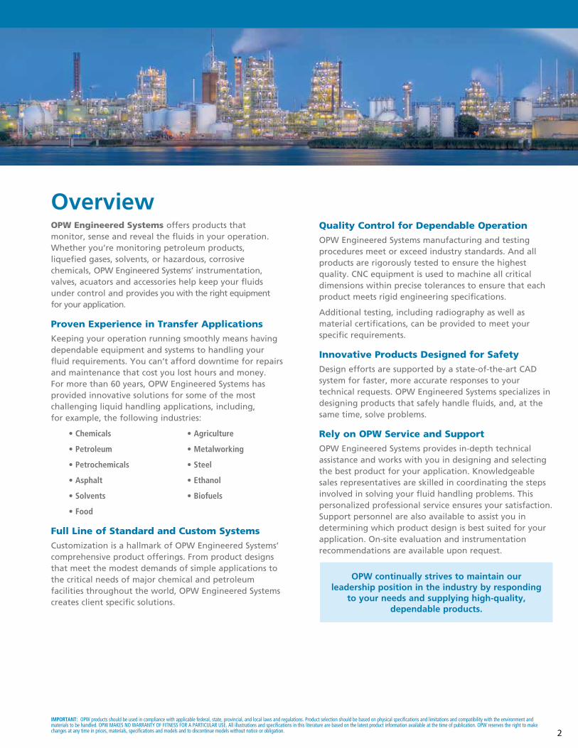
OPW Engineered Systems offers products that monitor, sense and reveal the fluids in your operation. Whether you’re monitoring petroleum products, liquefied gases, solvents, or hazardous, corrosive chemicals, OPW Engineered Systems’ instrumentation, valves, acuators and accessories help keep your fluids under control and provides you with the right equipment for your application.
Proven Experience in Transfer Applications
Keeping your operation running smoothly means having dependable equipment and systems to handling your fluid requirements. You can’t afford downtime for repairs and maintenance that cost you lost hours and money. For more than 60 years, OPW Engineered Systems has provided innovative solutions for some of the most challenging liquid handling applications, including, for example, the following industries:
• Chemicals • Agriculture
• Petroleum • Metalworking
• Petrochemicals • Steel
• Asphalt • Ethanol
• Solvents • Biofuels
• Food
Full Line of Standard and Custom Systems
Customization is a hallmark of OPW Engineered Systems’ comprehensive product offerings. From product designs that meet the modest demands of simple applications to the critical needs of major chemical and petroleum facilities throughout the world, OPW Engineered Systems creates client specific solutions.
Quality Control for Dependable Operation
OPW Engineered Systems manufacturing and testing procedures meet or exceed industry standards. And all products are rigorously tested to ensure the highest quality. CNC equipment is used to machine all critical dimensions within precise tolerances to ensure that each product meets rigid engineering specifications.
Additional testing, including radiography as well as material certifications, can be provided to meet your specific requirements.
Innovative Products Designed for Safety
Design efforts are supported by a state-of-the-art CAD system for faster, more accurate responses to your technical requests. OPW Engineered Systems specializes in designing products that safely handle fluids, and, at the same time, solve problems.
Rely on OPW Service and Support
OPW Engineered Systems provides in-depth technical assistance and works with you in designing and selecting the best product for your application. Knowledgeable sales representatives are skilled in coordinating the steps involved in solving your fluid handling problems. This personalized professional service ensures your satisfaction. Support personnel are also available to assist you in determining which product design is best suited for your application. On-site evaluation and instrumentation recommendations are available upon request.
2
Overview
OPW continually strives to maintain ourleadership position in the industry by responding
to your needs and supplying high-quality,dependable products .
3www.opw-es.com
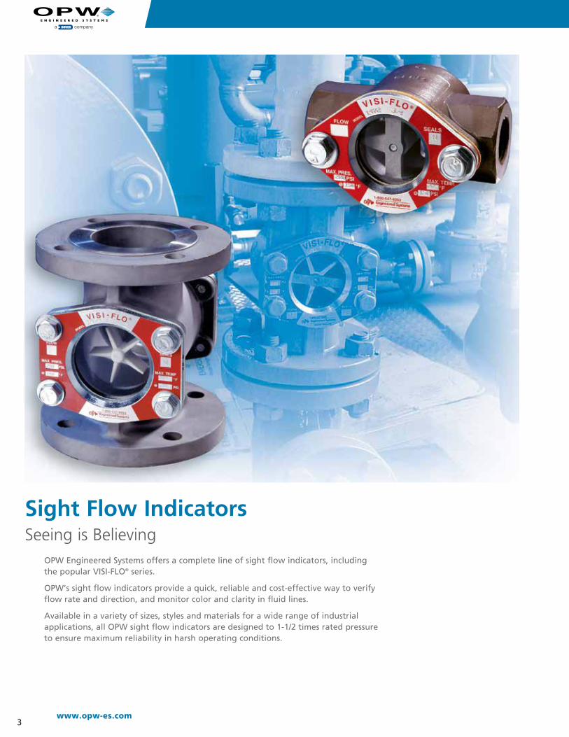
OPW Engineered Systems offers a complete line of sight flow indicators, including the popular VISI-FLO® series.
OPW’s sight flow indicators provide a quick, reliable and cost-effective way to verify flow rate and direction, and monitor color and clarity in fluid lines.
Available in a variety of sizes, styles and materials for a wide range of industrial applications, all OPW sight flow indicators are designed to 1-1/2 times rated pressureto ensure maximum reliability in harsh operating conditions.
Sight Flow IndicatorsSeeing is Believing

4
IMPORTANT: OPW products should be used in compliance with applicable federal, state, provincial, and local laws and regulations. Product selection should be based on physical specifications and limitations and compatibility with the environment and materials to be handled. OPW MAKES NO WARRANTY OF FITNESS FOR A PARTICULAR USE. All illustrations and specifications in this literature are based on the latest product information available at the time of publication. OPW reserves the right to make changes at any time in prices, materials, specifications and models and to discontinue models without notice or obligation.
• Elastomer radial seal with shape memory retention creates a steady sealing force between the outside diameter of the lens and the sight flow indicator body.
• PTFE lip/spring seal with constant spring expansion force maintains sealing by holding the edges of the PTFE lip seal against the outside diameter of the glass and the sight flow indicator body.
VISI-FLO® Bolt-On Design
Easy Access Bolt-On DesignVISI-FLO’s® unique bolt-on design fastens the face plate assembly directly to the body with no special torquing sequence. This provides quick, complete access to the unit from the front side, which gives companies the flexibility to install VISI-FLO® in locations where other sight flow indicators cannot be installed due to clearance limitations. Tie rod design sight flow indicators present challenges when fastening the lens and seal to the body.
Note: VISI-FLO’s® unparalleled modular design allows maintenance personnel to interchange or replace internal assemblies without taking the indicator out of the line. This optimizes uptime and saves on replacement and reordering costs.
An Insightful View into how these Cost-Efficient Visual Monitors can help controlIndustrial Fluid Processes
*Bridge design not used in 3" and 4" sizes
Cap
Gasket
Indicator
Body
Retaining Bridge*SealGlass
Sight Flow Indicators
Tie Rod Design
Dollar for dollar, sight flow indicators are the most cost efficient and effective way to visually monitor the flow of fluids and to determine where, if any, problems exist along the industrial process line.
These devices – install directly in the process line – allowing operators to observe flow rate, direction, color and clarity.
Readings are performed through a glass viewing lens.
Sight flow indicators can be deployed in one of two ways: (1) either individually at critical points along fluid lines where changes, interruptions or contamination of fluids are likely to occur; or (2) together in banks where the simultaneous monitoring of multiple fluid lines is necessary.
No-Leak GuaranteeUnlike traditional sight flow indicators that use conventional flat seals, VISI-FLO is guaranteed to be leak-free for three full years under normal use .
5www.opw-es.com
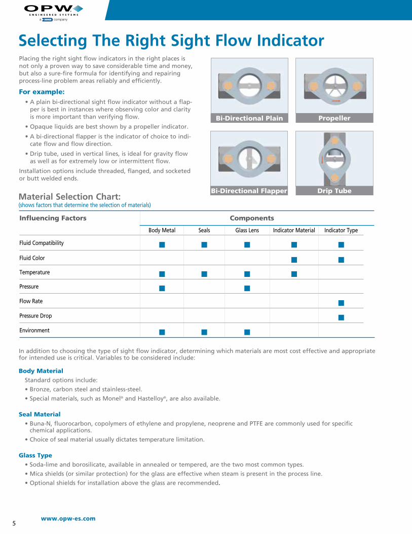
Placing the right sight flow indicators in the right places is not only a proven way to save considerable time and money, but also a sure-fire formula for identifying and repairing process-line problem areas reliably and efficiently.
For example:• A plain bi-directional sight flow indicator without a flap-
per is best in instances where observing color and clarity is more important than verifying flow.
• Opaque liquids are best shown by a propeller indicator.
• A bi-directional flapper is the indicator of choice to indi-cate flow and flow direction.
• Drip tube, used in vertical lines, is ideal for gravity flow as well as for extremely low or intermittent flow.
Installation options include threaded, flanged, and socketed or butt welded ends.
In addition to choosing the type of sight flow indicator, determining which materials are most cost effective and appropriate for intended use is critical. Variables to be considered include: Body Material
Standard options include:
• Bronze, carbon steel and stainless-steel.
• Special materials, such as Monel® and Hastelloy®, are also available.
Seal Material
• Buna-N, fluorocarbon, copolymers of ethylene and propylene, neoprene and PTFE are commonly used for specific chemical applications.
• Choice of seal material usually dictates temperature limitation.
Glass Type
• Soda-lime and borosilicate, available in annealed or tempered, are the two most common types.
• Mica shields (or similar protection) for the glass are effective when steam is present in the process line.
• Optional shields for installation above the glass are recommended.
Selecting The Right Sight Flow Indicator
Influencing Factors Components
Body Metal Seals Glass Lens Indicator Material Indicator Type
Fluid Compatibility n n n n n
Fluid Color n n
Temperature n n n n
Pressure n n
Flow Rate n
Pressure Drop n
Environment n n n
Material Selection Chart: (shows factors that determine the selection of materials)
Propeller
Bi-Directional Flapper
Bi-Directional Plain
Drip Tube
6
IMPORTANT: OPW products should be used in compliance with applicable federal, state, provincial, and local laws and regulations. Product selection should be based on physical specifications and limitations and compatibility with the environment and materials to be handled. OPW MAKES NO WARRANTY OF FITNESS FOR A PARTICULAR USE. All illustrations and specifications in this literature are based on the latest product information available at the time of publication. OPW reserves the right to make changes at any time in prices, materials, specifications and models and to discontinue models without notice or obligation.
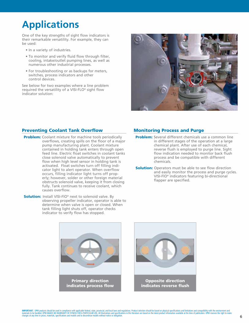
ApplicationsOne of the key strengths of sight flow indicators is their remarkable versatility. For example, they can be used:
• In a variety of industries.
• To monitor and verify fluid flow through filter, cooling, intake/outlet pumping lines, as well as numerous other industrial processes.
• For troubleshooting or as backups for meters, switches, process indicators and other control devices.
See below for two examples where a line problem required the versatility of a VISI-FLO® sight flow indicator solution:
Preventing Coolant Tank Overflow Problem: Coolant mixture for machine tools periodically
overflows, creating spills on the floor of a major pump manufacturing plant. Coolant mixture contained in holding tank enters through open feed line. Electric float switches in coolant tanks close solenoid valve automatically to prevent flow when high level sensor in holding tank is activated. Float switches turn off filling indi-cator light to alert operator. When overflow occurs, filling indicator light turns off prop-erly; however, solder or other foreign material obstructs solenoid valve, keeping it from closing fully. Tank continues to receive coolant, which causes overflow.
Solution: Install VISI-FlO® next to solenoid valve. By observing propeller indicator, operator is able to determine when valve is open or closed. When tank filling light shuts off, operator checks
indicator to verify flow has stopped.
Monitoring Process and Purge Problem: Several different chemicals use a common line in different stages of the operation at a large chemical plant. After use of each chemical, reverse flush is employed to purge line. Sight
flow indication needed to monitor back flush process and be compatible with different
chemicals.
Solution: Operators must be able to see flow direction and easily monitor the process and purge cycles.
VISI-FlO® indicators featuring bi-directional flapper are specified.
Primary direction indicates process flow
Opposite direction indicates reverse flush
7www.opw-es.com
Power PlantsNew Power Plants: Sight flow indicators moni-tor the flow of critical fluids, such as lubricants pumped to turbines in hydro-electric generators and water in cooling lines.
Older Power Plants: New, more reliable sight flow indicators replace aging models (and additional indicators are also deployed) during upgrades.
Wastewater TreatmentVISI-FLO® sight flow indicators visually monitor the filtering process.
The most common point of installation: second stage aeration tank pumping lines.
The purpose: verify sludge removal to ensure efficient aeration.
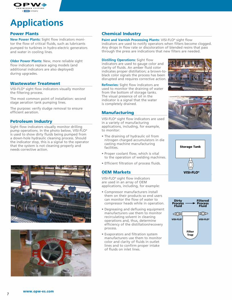
Petroleum Industry Sight flow indicators visually monitor drilling pump operations. In the photo below, VISI-FLO® is used to show dirty fluids being pumped from a down-hole hydraulic cleaning process. Should the indicator stop, this is a signal to the operator that the system is not cleaning properly and needs corrective action.
Chemical Industry Paint and Varnish Processing Plants: VISI-FLO® sight flow indicators are used to notify operators when filters become clogged. Any drops in flow rate or discoloration of blended resins that pass through the press are indications that new filters are needed.
Distilling Operations: Sight flow indicators are used to gauge color and clarity of fluids. An amber fluid color indicates proper distillation; a brown-to-black color signals the process has been disrupted and requires corrective action.
Refineries: Sight flow indicators are used to monitor the draining of water from the bottom of storage tanks.The visual presence of oil in the indicator is a signal that the wateris completely drained.
ManufacturingVISI-FLO® sight flow indicators are used in a variety of manufacturing applications, including, for example,to monitor:
• The draining of hydraulic oil from nitrogen charged accumulators in die casting machine manufacturing
facilities.
• Proper coolant flow, which is vital to the operation of welding machines.
• Efficient filtration of process fluids.
OEM MarketsVISI-FLO® sight flow indicators are used in an array of OEM applications, including, for example:
• Compressor manufacturers install them on their products so end users can monitor the flow of water to compressor heads while in operation.
• Degreasing and defluxing equipment manufacturers use them to monitor recirculating solvent in cleaning operations and, thus, determine efficiency of the distillation/recovery process.
• Evaporators and filtration system manufacturers use them to monitor color and clarity of fluids in outlet lines and to confirm proper intake of fluids on inlet lines.
FilterTrap
VISI-FLO®VISI-FLO®
Filtered Process
Fluid
Storage Tank
VISI-FLO®
Dirty Process
Fluid
Applications
8
IMPORTANT: OPW products should be used in compliance with applicable federal, state, provincial, and local laws and regulations. Product selection should be based on physical specifications and limitations and compatibility with the environment and materials to be handled. OPW MAKES NO WARRANTY OF FITNESS FOR A PARTICULAR USE. All illustrations and specifications in this literature are based on the latest product information available at the time of publication. OPW reserves the right to make changes at any time in prices, materials, specifications and models and to discontinue models without notice or obligation.
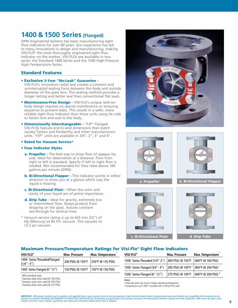
1400 & 1500 Series (Flanged) OPW Engineered Systems has been manufacturing sight flow indicators for over 60 years. Our experience has led to many innovations in design and manufacturing, making VISI-FLO® the most thoroughly engineered sight flow indicator on the market. VISI-FLOs are available in two series: the Standard 1400 Series and the 1500 High-Pressure High-Temperature Series.
Standard Features
• Exclusive 3-Year “No-Leak” Guarantee - VISI-FLO’s innovative radial seal creates a constant and uninterrupted sealing force between the body and outside diameter of the glass lens. This sealing method provides a longer lasting and better seal than conventional flat seals.
• Maintenance-Free Design - VISI-FLO’s unique, bolt-on-body design requires no special maintenance or torquing sequence to prevent leaks. This results in a safer, more reliable sight flow indicator than those units using tie rods to fasten lens and seal to the body.
• Dimensionally Interchangeable - “FJP” Flanged VISI-FLOs feature end-to-end dimensions that match Jacoby-Tarbox and Penberthy and other manufacturers’ units. “FJP” units are available in 3/4", 2", 3" and 4".
• Rated for Vacuum Service*
• Four Indicator Styles
a. Propeller - The best way to show flow of opaque liq-uids. Ideal for observation at a distance. Flow from right to left is standard. Specify if left to right flow is needed. Not recommended for flow rates above 100 gallons per minute (GPM).
b. Bi-Directional Flapper - This indicator points in either direction to show you at a glance which way the liquid is flowing.
c. Bi-Directional Plain - When the color and clarity of your liquid are of prime importance.
d. Drip Tube - Ideal for gravity, extremely low or intermittent flow. Keeps product from dripping on the glass. Assures constant see-through for vertical lines.
* Vacuum service rating is up to 635 mm (25") of Hg (Mercury) at 85.5% vacuum. This equates to 12.3 psi vacuum.
Maximum Pressure/Temperature Ratings for Visi-Flo® Sight Flow Indicators
a. Propeller b. Bi-Directional Flapper
c. Bi-Directional Plain d. Drip Tube
1 With standard seals 2 Stainless-steel units rated @ 195 PSIG 3 Stainless-steel units rated @ 195 PSIG 4 Stainless-steel units rated @ 275 PSIG
VISI-FLO® Max. Pressure Max. Temperature 1
1400 Series Threaded/Flanged (1/4"- 4")
200 PSIG @ 150°F 250°F @ 135 PSIG
1400 Series Flanged (6"-12") 150 PSIG @ 150°F 150°F @ 150 PSIG
VISI-FLO® Max. Pressure Max. Temperature 1
1500 Series Threaded (1/4"-2") 400 PSIG @ 150°F 400°F @ 160 PSIG
1500 Series Flanged (3/4"- 4") 285 PSIG @ 100°F 4 400°F @ 200 PSIG 3
1500 Series Flanged (6"-12") 275 PSIG @ 100°F 400°F @ 200 PSIG ²
Notes: • Alternate seals may result in higher operating temperatures• Temperatures up to 500º F possible with Hi-Temp PTFE seals
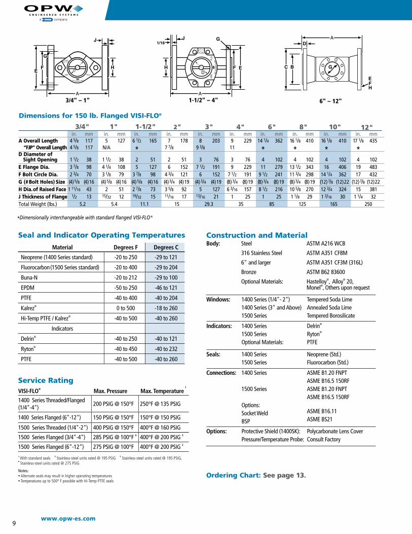
9www.opw-es.com
D
C B
in. mm in. mm in. mm in. mm in. mm in. mm in. mm in. mm in. mm in. mm A Overall Length 4 5/8 117 5 127 6 1/2 165 7 178 8 203 9 229 14 1/4 362 16 1/8 410 16 1/8 410 17 1/8 435
“FJP” Overall Length 4 5/8 117 N/A * 7 7/8 9 3/8 11 * * * *D Diameter of Sight Opening 1 1/2 38 1 1/2 38 2 51 2 51 3 76 3 76 4 102 4 102 4 102 4 102E Flange Dia. 3 7/8 98 4 1/4 108 5 127 6 152 7 1/2 191 9 229 11 279 13 1/2 343 16 406 19 483F Bolt Circle Dia. 2 3/4 70 3 1/8 79 3 7/8 98 4 3/4 121 6 152 7 1/2 191 9 1/2 241 11 3/4 298 14 1/4 362 17 432G (# Bolt Holes) Size (4)5/8 (4) 16 (4)5/8 (4) 16 (4)5/8 (4) 16 (4)3/4 (4) 19 (4)3/4 (4) 19 (8)3/4 (8) 19 (8)3/4 (8) 19 (8)3/4 (8) 19 (12)7/8 (12) 22 (12)7/8 (12) 22H Dia. of Raised Face 1 11/16 43 2 51 2 7/8 73 3 5/8 92 5 127 6 3/16 157 8 1/2 216 10 5/8 270 12 3/4 324 15 381J Thickness of Flange 1/2 13 15/32 12 19/32 15 11/16 17 13/16 21 1 25 1 25 1 1/8 29 1 3/16 30 1 1/4 32Total Weight (lbs.) 5.2 5.4 11.1 15 29.3 35 85 125 165 250
3/4" 1" 1-1/2" 2" 3" 4" 6" 8" 10" 12"
3/4" – 1"
*Dimensionally interchangeable with standard flanged VISI-FLO ®
Dimensions for 150 lb. Flanged VISI-FLO®
Ordering Chart: See page 13.
1-1/2" – 4" 6" – 12"
Construction and MaterialBody: Steel ASTM A216 WCB
316 Stainless Steel ASTM A351 CF8M
6" and larger ASTM A351 CF3M (316L)
Bronze ASTM B62 83600
Optional Materials: Hastelloy®, Alloy® 20, Monel®, Others upon request
Windows: 1400 Series (1/4"- 2") 1400 Series (3" and Above) 1500 Series
Tempered Soda Lime Annealed Soda Lime Tempered Borosilicate
Indicators: 1400 Series 1500 Series Optional Materials:
Delrin® Ryton® PTFE
Seals: 1400 Series 1500 Series
Neoprene (Std.) Fluorocarbon (Std.)
Connections: 1400 Series
1500 Series Options: Socket WeldBSP
ASME B1.20 FNPT ASME B16.5 150RFASME B1.20 FNPT ASME B16.5 150RF
ASME B16.11 ASME BS21
Options: Protective Shield (1400SK): Pressure/Temperature Probe:
Polycarbonate Lens Cover Consult Factory
Service Rating
Material Degrees F Degrees C
Neoprene (1400 Series standard) -20 to 250 -29 to 121
Fluorocarbon (1500 Series standard) -20 to 400 -29 to 204
Buna-N -20 to 212 -29 to 100
EPDM -50 to 250 -46 to 121
PTFE -40 to 400 -40 to 204
Kalrez® 0 to 500 -18 to 260
Hi-Temp PTFE / Kalrez® -40 to 500 -40 to 260
Indicators
Delrin® -40 to 250 -40 to 121
Ryton® -40 to 450 -40 to 232
PTFE -40 to 500 -40 to 260
1 With standard seals 2 Stainless-steel units rated @ 195 PSIG 3 Stainless-steel units rated @ 195 PSIG, 4 Stainless-steel units rated @ 275 PSIG
Notes: • Alternate seals may result in higher operating temperatures• Temperatures up to 500º F possible with Hi-Temp PTFE seals
1500 Series Flanged (3/4"-4") 285 PSIG @ 100°F 4 400°F @ 200 PSIG 3
1500 Series Flanged (6"-12") 275 PSIG @ 100°F 400°F @ 200 PSIG 2
VISI-FLO® Max. Pressure Max. Temperature 1
1400 Series Threaded/Flanged (1/4"-4")
200 PSIG @ 150°F 250°F @ 135 PSIG
1400 Series Flanged (6"-12") 150 PSIG @ 150°F 150°F @ 150 PSIG
1500 Series Threaded (1/4"-2") 400 PSIG @ 150°F 400°F @ 160 PSIG
Seal and Indicator Operating Temperatures
10
IMPORTANT: OPW products should be used in compliance with applicable federal, state, provincial, and local laws and regulations. Product selection should be based on physical specifications and limitations and compatibility with the environment and materials to be handled. OPW MAKES NO WARRANTY OF FITNESS FOR A PARTICULAR USE. All illustrations and specifications in this literature are based on the latest product information available at the time of publication. OPW reserves the right to make changes at any time in prices, materials, specifications and models and to discontinue models without notice or obligation.
1400 & 1500 Series (Threaded) OPW Engineered Systems has been manufacturing sight flow indicators for over 60 years. Our experience has led to many innovations in design and manufacturing, making VISI-FLO® the most thoroughly-engineered sight flow indicator on the market. VISI-FLOs are available in two series: the Standard 1400 Series, and the 1500 High-Pressure High-Temperature Series.
Standard Features
• Exclusive 3-Year “No-Leak” Guarantee - VISI-FLO’s innovative radial seal creates a constant and uninterrupted sealing force between the body and outside diameter of the glass lens. This sealing method provides a longer lasting and better seal than conventional flat seals.
• Maintenance-Free Design - VISI-FLO’s unique, bolt-on-body design requires no special maintenance or torquing sequence to prevent leaks. This results in a safer, more reliable sight flow indicator than units using tie rods to fasten lens and seal to body.
• Rated for Vacuum Service*
• Four Indicator Styles
a. Propeller - The best way to show flow of opaque liquids. Ideal for observation at a distance. Flow from right to left is standard. Specify if left to right flow is needed. Not recommended for flow rates above 100 gallons per minute (GPM).
b. Bi-Directional Flapper - This indicator points in either direction to show you at a glance which way the liquid is flowing.
c. Bi-Directional Plain - When the color and clarity of your liquid are of prime importance.
d. Drip Tube - Ideal for gravity, extremely low or intermittent flow. Keeps product from dripping on the glass. Assures constant see-through for vertical lines.
• On 2" and Smaller Units - bottom PTFE spacer eliminates seal deformation due to pressure cycling.
* Vacuum service rating is up to 635 mm (25”) of Hg (Mercury) at 85.5% vacuum. This equates to 12.3 psi vacuum.
a. Propeller b. Bi-Directional Flapper
c. Bi-Directional Plain d. Drip Tube
Maximum Pressure/Temperature Ratings for Visi-Flo® Sight Flow Indicators
1 With standard seals 2 Stainless-steel units rated @ 195 PSIG 3 Stainless-steel units rated @ 195 PSIG 4 Stainless-steel units rated @ 275 PSIG
VISI-FLO® Max. Pressure Max. Temperature 1
1400 Series Threaded/Flanged (1/4"- 4")
200 PSIG @ 150°F 250°F @ 135 PSIG
1400 Series Flanged (6"-12") 150 PSIG @ 150°F 150°F @ 150 PSIG
VISI-FLO® Max. Pressure Max. Temperature 1
1500 Series Threaded (1/4"-2") 400 PSIG @ 150°F 400°F @ 160 PSIG
1500 Series Flanged (3/4"- 4") 285 PSIG @ 100°F 4 400°F @ 200 PSIG 3
1500 Series Flanged (6"-12") 275 PSIG @ 100°F 400°F @ 200 PSIG ²
Notes: • Alternate seals may result in higher operating temperatures• Temperatures up to 500º F possible with Hi-Temp PTFE seals

11www.opw-es.com
in. mm in. mm in. mm in. mm in. mm in. mm in. mm in. mmA Overall Length 3 1⁄4* 83 3 1⁄4* 83 3 1⁄4* 83 4 1⁄4** 108 4 1⁄4** 108 5 1⁄4*** 133 5 1⁄4*** 133 5 1⁄2*** 140 B Overall Width 2 51 2 51 2 51 2 9⁄16 65 2 9⁄16 65 3 5⁄16 84 3 5⁄16 84 3 5⁄16 84 C Overall Height (1400 series) 2 3⁄8 60 2 3⁄8 60 2 3⁄8 60 3 1⁄4 83 3 1⁄4 83 4 5⁄16 110 4 55⁄16 110 4 5⁄16 110 Overall Height (1500 series) 2 9⁄16 65 2 9⁄16 65 2 9⁄16 65 3 7⁄16 87 3 7⁄16 87 4 1⁄2 114 4 1⁄2 114 4 1⁄2 114 D Diameter of Sight Opening 1 1⁄8 29 1 1⁄8 29 1 1⁄8 29 1 1⁄2 38 1 1⁄2 38 2 51 2 51 2 51 K Added Height Due to Shield 7⁄16 11 7⁄16 11 7⁄16 11 1⁄2 13 1⁄2 13 11⁄2 13 1⁄2 13 1⁄2 13 Total Weight (lbs .) 1.6 1.6 1.4 3.0 2.7 8.4 7.9 6.6
* Stainless-steel units are 3 5/8" **Bronze units are 4 1/8" *** Stainless-steel units are 5 5/8"
1/4" 3/8" 1/2" 3/4" 1" 1-1/4" 1-1/2" 2"
1/4" – 1"
1/4" – 2"
General Dimensions for Threaded VISI-FLO®
Construction and MaterialBody: Steel ASTM A216 WCB
316 Stainless Steel ASTM A351 CF8M6" and larger ASTM A351 CF3M (316L)Bronze ASTM B62 83600
Optional Materials: Hastelloy®, Alloy® 20, Monel®, Others upon request
Windows: 1400 Series (1/4"- 2") 1400 Series (3" and Above) 1500 Series
Tempered Soda Lime Annealed Soda Lime Tempered Borosilicate
Indicators: 1400 Series 1500 Series Optional Materials:
Delrin® Ryton® PTFE
Seals: 1400 Series 1500 Series
Neoprene (Std.) Fluorocarbon (Std.)
Connections: 1400 Series
1500 Series Options: Socket WeldBSP
ASME B1.20 FNPT ASME B16.5 150RFASME B1.20 FNPT ASME B16.5 150RF
ASME B16.11 ASME BS21
Options: Protective Shield (1400SK): Pressure/Temperature Probe:
Polycarbonate Lens Cover Consult Factory
Service Rating
1 With standard seals 2 Stainless-steel units rated @ 195 PSIG 3 Stainless-steel units rated @ 195 PSIG 4 Stainless-steel units rated @ 275 PSIG
Notes: • Alternate seals may result in higher operating temperatures• Temperatures up to 500º F possible with Hi-Temp PTFE seals
1500 Series Flanged (3/4"-4") 285 PSIG @ 100°F 4 400°F @ 200 PSIG 3
1500 Series Flanged (6"-12") 275 PSIG @ 100°F 400°F @ 200 PSIG 2
VISI-FLO® Max. Pressure Max. Temperature 1
1400 Series Threaded/Flanged (1/4"-4")
200 PSIG @ 150°F 250°F @ 135 PSIG
1400 Series Flanged (6"-12") 150 PSIG @ 150°F 150°F @ 150 PSIG
1500 Series Threaded (1/4"-2") 400 PSIG @ 150°F 400°F @ 160 PSIG
Material Degrees F Degrees C
Neoprene (1400 Series standard) -20 to 250 -29 to 121
Fluorocarbon (1500 Series standard) -20 to 400 -29 to 204
Buna-N -20 to 212 -29 to 100
EPDM -50 to 250 -46 to 121
PTFE -40 to 400 -40 to 204
Kalrez® 0 to 500 -18 to 260
Hi-Temp PTFE / Kalrez® -40 to 500 -40 to 260
Indicators
Delrin® -40 to 250 -40 to 121
Ryton® -40 to 450 -40 to 232
PTFE -40 to 500 -40 to 260
Seal and Indicator Operating Temperatures

IMPORTANT: OPW products should be used in compliance with applicable federal, state, provincial, and local laws and regulations. Product selection should be based on physical specifications and limitations and compatibility with the environment and materials to be handled. OPW MAKES NO WARRANTY OF FITNESS FOR A PARTICULAR USE. All illustrations and specifications in this literature are based on the latest product information available at the time of publication. OPW reserves the right to make changes at any time in prices, materials, specifications and models and to discontinue models without notice or obligation. 12
www.opw-es.com
Benefits• Economical prices
• Allows you to quickly verify flow, and monitor color and clarity in fluid lines
• 48-hour delivery available to help mini-mize down time
Standard Features• Brass construction
• Single and double window designs
• Sizes from 1/8"- 2"
• 125 psig pressure rating
• Available with or without rotor
• FNPT or BSPT connections
1600 Series OPW 1600 Series Sight Flow Indicators are manufactured of quality materials and safety tested to assure long, depend-able service at economical prices. Good for monitoring critical fluid flow, lubricant, coolant lines and sprinkler systems.
Physical DataMaximum Pressure: 125 psigMaximum Temp.: 200° F (93° C)Seals: Buna-N standard on
all 1600 Series. Alternative seals available on request.
Glass Type: Tempered Soda limeThreads: NPT or BSPTIndicator: Delrin®
Body: Bronze
Call OPW Customer Service at 800-547-9393 for complete ordering information1600 Series 1600 Series
General Dimensions for 1600 Series Size 1⁄8"– 3⁄8" 1⁄2"– 3⁄4" 1" – 1 1⁄4" 1 1⁄2" – 2" A Overall Length 3 3⁄16" 3 13⁄16" 4 3⁄8" 4 5⁄8" B Overall Height 2 1⁄8" 2 7⁄16" 3 1⁄8" 4" C Overall Width 2 7⁄32" 2 7⁄16" 3" 3 13⁄16"
13www.opw-es.com
Maximum Pressure/Temperature Ratings
Your guide to the industry’s most complete line of sight flow indicators
Seal Materials1 - Buna-N 2 - Fluorocarbon (Std. 1500 Series) 3 - PTFE 4 - EPDM 5 - Neoprene (Std. 1400 Series) 6 - Kalrez® 7 - PTFE - High Temperature X - Customer Specified
Sight Flow Indicators
Unique radial seal prevents leakage
Bolted glass retainers eliminate routine maintenance
Four indicator choices cover every application
Flow monitoring made easy• Quick, reliable flow verification• Easy monitoring of fluid color and clarity• Economical, maintenance-free design• 3-year warranty, guaranteed not to leak
Series14 - 1400 Series 15 - 1500 Series
See charts below for temperature and pressure ratings.
Indicator0 - Plain 1 - Propeller (1/4" to 4" only) 2 - Flapper 3 - Drip Tube 4 - Low Flow (1/4", 3/8", 1/2" only)
Indicator MaterialD - Delrin® (Std. 1400 Series, white) R - Ryton® (Std. 1500 Series, brown) T - PTFE (Std. 6" - 12", white) C - Carbon Steel (Drip Tubes only) S - Stainless-steel (Drip Tubes only)
End ConnectionsBlank - FNPT F - ASME 150 Lb. Flange B - British Threaded FJP - Flanged Replacement FT - ASME 300 Lb. Flange SW - Socket Weld
ShieldingBlank - Not Shielded SK - Shielded
Ordering Chart Call OPW Customer Service at 800-547-9393 for complete ordering information
Availability of styles, sizes and materials may vary depending upon VISI-FLO configuration.Consult OPW Customer Service regarding your exact requirements.
Indicator Styles
Plain - When fluid color/clarity is of prime importance (bi-directional)
Propeller - Ideal for opaque fluids and observation from a distance
(right to left flow std., specify other)
Flapper - Points in either direction to show fluid flow (bi-directional)
Drip Tube - Ideal for gravity, intermittent or extremely low flow; prevents fluid from dripping on glass
(vertical lines only)
001 - 1/8"002 - 1/4"004 - 3/8"005 - 1/2"007 - 3/4"
010 - 1"012 - 1-1/4"015 - 1-1/2"020 - 2"030 - 3"
040 - 4"060 - 6"080 - 8"100 - 10"120 - 12"
1400 SeriesStandard pressure/temperature
units in flanged and threaded styles
1500 SeriesHigh pressure/temperature units
in flanged and threaded styles
Construction2 - Carbon Steel3 - Bronze7 - 316 Stainless-steel9 - Alloy 20Other construction materials available
Size
1400 Series End Connection Max. ASME Pressure Max. Temperature1 FThreaded/Flanged 200 PSIG at 150°F 250°F at 135 PSIG (1/4" - 4")
Flanged (6" - 12") 150 PSIG at 150°F 150°F at 150 PSIG
1 With standard seals 2 Stainless-steel units rated @ 195 PSIG 3 Stainless-steel units rated @ 195 PSIG 4 Stainless-steel units rated @ 275 PSIG
Maximum Pressure/Temperature Ratings1500 Series End Connection Max. ASME Pressure Max. Temperature1
Threaded (1/4" - 2") 400 PSIG at 150°F 400°F at 160 PSIGFlanged (3/4" - 4") 285 PSIG at 100°F4 400°F at 200 PSIG3
Flanged (6" - 12") 275 PSIG at 100°F 400°F at 200 PSIG2
1 5 2 0 R F - 0 2 0 1
Notes: • Alternate seals may result in higher operating temperatures• Temperatures up to 500º F possible with Hi-Temp PTFE seals
Temperature Range for Seal MaterialsDegrees F Degrees C
Seal Material Min. Max. Min. Max.Neoprene (400 Series standard) -20 250 -29 121Fluorocarbon (1500 Series standard) -20 400 -29 204
Buna-N -20 212 -29 100EPDM -50 250 -46 121PTFE -40 400 -40 204Kalrez® 0 500 -18 260Hi-Temp PTFE / Kalrez® -40 500 -40 260Indicator MaterialDelrin® -40 250 -40 204Ryton® -40 450 -40 204PTFE -40 500 -40 204
IMPORTANT: OPW products should be used in compliance with applicable federal, state, provincial, and local laws and regulations. Product selection should be based on physical specifications and limitations and compatibility with the environment and materials to be handled. OPW MAKES NO WARRANTY OF FITNESS FOR A PARTICULAR USE. All illustrations and specifications in this literature are based on the latest product information available at the time of publication. OPW reserves the right to make changes at any time in prices, materials, specifications and models and to discontinue models without notice or obligation. 14
The OPW Engineered Systems patented gauge isolation ring, called ISO-Ring®, is designed to isolate gauges or pressure switches from solids in process flow and to ensure accurate pressure readings.
Clogging or fouling typically associated with diaphragm seals used in viscous fluid applications result in erroneous pressure readings. This is never a problem with the OPW ISO-Ring®.
ISO-Ring® utilizes a specially designed flush-mounted flexible inner cylinder, behind which is a clean, captive liquid. As process liquid flows through the pipe, it exerts pressure through the flexible cylinder to the captive liquid. Pressure is monitored by the gauge or the switch, which is completely isolated from the process flow.
The OPW Engineered Systems ISO-Ring is the same unit as the Ronningen-Petter unit . OPW Engineered Systems purchased the entire product line from them in 1996 . Product specifications that currently read Ronningen-Petter ISO-Ring products should be changed to read OPW Engineered Systems products .
Unlike Diaphragm Seals, Non-Plugging Gauge Isolation Ring Assures Reliable Pressure Ratings
ISO-Ring®
Direct Diaphragm Seal
iSO-ring®
15www.opw-es.com
ISO-Ring® For years now, a common refrain has reverberated through-out the industrial world with an unmistakably clear message:
Out with the diaphragm seal. In with the OPW Engineered Systems’ ISO-Ring®.
For the growing number of companies that have embraced and implemented this simple call-to-action, something pow-erfully refreshing and highly reassuring has happened as process liquid has flowed through their pipes:
Process flow is smooth and uninterrupted; pressure readings are consistently reliable and accurate.
Thanks to OPW Engineered Systems’ advanced, patented gauge isolation ring, gone are the days when solids from the process flow plug the pressure-sensing mechanism or clog the access port on the diaphragm seal.
Features & Benefits• Gauge (or switch) is in contact only with captive liquid and
never directly with the process liquid.• Isolating the gauge (or switch) from solids in process flow
results in accurate readings.• Gauge (or switch) can be removed for calibration, repair,
or replacement – without interrupting process flow.• Unique flexible cylinder prevents plugging, which means
pressure readings are reliable and accurate.• Integral design eliminates accidental breakage.• Adaptable to a variety of process conditions
and applications.• Will not clog (which is not true of diaphragm seals).
Ordering Information
Example: R CS 1 I 11 04 - 020 1
RING ORSPOOL
BODY MATERIAL
END FLANGE MATERIAL TYPE FILL GAUGE SIZE CYLINDER
MATERIALS
R = ISO Ring®
S = ISO Spool®
B = Bolt-Thru ISO-Ring®
CS = carb. stl. SS = 316 SST
1 = carb. stl. 2 = 316 SST 3 = carb. stl. w/
PTFE envelope*** 4 = 316 SST
PTFE envelope*** 5 = cpvc
(flat faced flange) 6 = cpvc - ISO-Spool only
(flat faced flange) 7 = other 8 = Fully Wetted PTFE
(Bolt-Thru ISO-Ring) carb. stl.
9 = Fully Wetted PTFE (Bolt-Thru ISO-Ring) 316 SST
N = without IRD** I = with IRD** T = Threaded* F = Flngd/150 Lb.* G = Flngd/300 Lb.*
00 = less fill 11 = propylene
glycol 12 = distilled water 13 = mineral oil 14 = silicone oil 15 = vegetable oil 16 = glycerine 17 = fluorolube 18 = fluorosilicone 19 = other
00 = less gauge; 1/4" 01 = less gauge; 1/2" conn. 02 = 0-60 psi 03 = 0-100 psi 04 = 0-200 psi 05 = 0-400 psi 06 = 0-600 psi 08 = customer supplied 09 = other
010 = 1" 015 = 1.5" 020 = 2" 025 = 2.5" 030 = 3" 040 = 4" 050 = 5" 060 = 6" 080 = 8" 100 = 10" 120 = 12" 140 = 14" 160 = 16" 180 = 18" 200 = 20"
1 = Buna-N 2 = Fluorocarbon 3 = PTFE 4 = EPDM 5 = silicone 6 = white buna 7 = natural rubber 8 = other
* Spool Only ** IRD (Instrument Removal Device): Permits easy removal of instrumentation for calibration, repair, or replacement without the need to shut down process flow. *** PTFE Flange Envelopes only available with PTFE cylinder.OPW Engineered Systems’ patented Iso-Ring technology is designed to isolate gauges or pressure switches from solids in process flow and assure accurate pressure readings. Clogging or fouling typically associated with diaphragm seals used in viscous fluid applications is never a problem. That's because Iso-Ring has a flush mounted flexible inner cylinder, behind which is a clean, captive liquid. As process liquid flows through the pipe, it exerts pressure through the flexible cylinder to the captive liquid. The gauge or switches sensing mechanism monitors the pressure. In other words, the gauge or switch is completely isolated from the flow.
IMPORTANT: OPW products should be used in compliance with applicable federal, state, provincial, and local laws and regulations. Product selection should be based on physical specifications and limitations and compatibility with the environment and materials to be handled. OPW MAKES NO WARRANTY OF FITNESS FOR A PARTICULAR USE. All illustrations and specifications in this literature are based on the latest product information available at the time of publication. OPW reserves the right to make changes at any time in prices, materials, specifications and models and to discontinue models without notice or obligation. 16
ISO-Spool® For Small Diameter PipingThis patented product is designed to provide a large sensing area in smaller pipe diameters from 1" to 4". Offered in both NPT threaded and flanged models and available with flat or raised face.
Dimensions ISO-Ring®
Pipe Size A B* Approx. Shipping Wt. in. mm in. mm lbs kg 2" 615⁄16" (176 mm) 2" (51 mm) 3 lbs (1.35 kg) 3" 83⁄16" (208 mm) 2" (51 mm) 6 lbs (2.70 kg) 4" 9" (229 mm) 11⁄2" (38 mm) 8 lbs (3.6 kg) 5" 101⁄4" (260 mm) 11⁄2" (38 mm) 10 lbs (4.5 kg) 6" 113⁄16" (284 mm) 11⁄2" (38 mm) 12 lbs (5.4 kg) 8" 133⁄8" (340 mm) 11⁄2" (38 mm) 16 lbs (7.3 kg) 10" 159⁄16" (395 mm) 11⁄2" (38 mm) 20 lbs (9.1 kg) 12" 179⁄16" (446 mm) 11⁄2" (44 mm) 25 lbs (11.4 kg) 14" 1915⁄16" (506 mm) 11⁄2" (44 mm) 50 lbs (22.7 kg) 16" 2115⁄16" (557 mm) 2" (51 mm) 60 lbs (27.2 kg) 18" 243⁄16" (614 mm) 2" (51 mm) 70 lbs (31.8 kg) 20" 261⁄16" (662 mm) 2" (51 mm) 80 lbs (36.3 kg)
*Add 1/4" to Units with CPVC Flanges
Specifications ISO-Ring® ISO-Spool®
Housing: Carbon Steel Carbon Steel 316 Stainless-steel 316 Stainless-steelAssembly Flanges: Carbon Steel Carbon Steel 316 Stainless-steel 316 Stainless-steel CPVC CPVC PTFE enveloped PTFE enveloped Inner Flexible Wall: Buna-N up to 225 ˚F (107 ˚C) PTFE up to 350 ˚F (177 ˚C) Silicone up to 450 ˚F (232 ˚C) Fluorocarbon up to 350 ˚F (177 ˚C) White Neoprene up to 225 ˚F (107 ˚C) Natural Rubber up to 225 ˚F (107 ˚C)Captive Sensing Liquid: 50% Water/50% Prop. Glycol -20 F to 200 ˚F (-29 ˚C to 93 ˚C) Silicone Oil (FDA Approved) -20 F to 450 ˚F (-29 ˚C to 232 ˚C) Fluorosilicone -20 F to 450 ˚F (-29 ˚C to 232˚ C) Mineral Oil 35 F to 225 ˚F (1.7 ˚C to 107 ˚C) Distilled Water 35 F to 200 ˚F (1.7 ˚C to 93.3 ˚C)
ISO-Spool® (flanged)
Pipe Size Class 150 Class 300 B Class 150 Class 300 in. mm in. mm in. mm in. mm in. mm
1" 41⁄4" (108 mm) 47⁄8” (124 mm) 53⁄8 lbs (136 mm) 8 lbs (3.6 kg) 9 lbs (4.1 kg) 11⁄2" 5" (127 mm) 61⁄8” (156 mm) 53⁄8 lbs (136 mm) 10 lbs (4.5 kg) 12 lbs (5.4 kg) 2" 6" (152 mm) – – 53⁄8 lbs (136 mm) 15 lbs (6.8 kg) – – 3" 71⁄2" (191 mm) – – 53⁄8 lbs (136 mm) 22 lbs (10.0 kg) – – 4" 9" (229 mm) – – 53⁄8 lbs (136 mm) 27 lbs (12.2 kg) – –
ISO-Spool® (threaded)
Pipe Size A B Approx. Shipping Wt. in. mm in. mm lbs kg 1" 39⁄16" (90 mm) 75⁄8" (194 mm) 10 lbs (4.5 kg) 11⁄2" 43⁄8" (111 mm) 77⁄8" (200 mm) 12 lbs (5.4 kg)
ISO-Rings®
Threaded ISO-Spool® Flanged ISO-Spool®
www.opw-es.com17
The design and engineering excellence of ISO-Ring® is embodied within a unique 360-degree flexible cylinder, behind which is a clean, captive liquid.
Here’s how it works and its significance:
As process liquid flows through the pipe, it exerts pressure. This pressure is transmitted through the ISO-Ring’s unique flexible cylinder to the captive liquid. The pressure exerted by the captive liquid is monitored by the gauge’s (or switch’s) sensing mechanism, which is completely isolated from the flow. The gauge (or switch), thus, comes in contact only with captive liquid and never directly with the process flow.
The result: the pressure-sensing mechanism never plugs.
ISO-Ring® has no access ports; consequently, there is nowhere for solids to collect and no openings that can plug. The inner flexible cylinder is the same diameter as the inner diameter of the piping, so it’s continually cleaned by the flowing liquid.
The result: pressure readings are reliable and more accurate.
In addition, ISO-Ring® pressure readings represent the circumferential average of the pipe’s internal pressure distribution (not just the pressure at a single point in the line, which is all you get with a diaphragm seal).
The result: pressure readings are more consistent.
ISO-Ring®
Sets Standard for Reliable Pressure Ratings
DIRECT
DIAPHRAGM SEAL
ISO-RING®
FLEXIBLE CYLINDERHOUSING
CAPTIVE LIQUID
NEEDLE VALVE
FLANGE ASSEMBLY
IMPORTANT: OPW products should be used in compliance with applicable federal, state, provincial, and local laws and regulations. Product selection should be based on physical specifications and limitations and compatibility with the environment and materials to be handled. OPW MAKES NO WARRANTY OF FITNESS FOR A PARTICULAR USE. All illustrations and specifications in this literature are based on the latest product information available at the time of publication. OPW reserves the right to make changes at any time in prices, materials, specifications and models and to discontinue models without notice or obligation. 18
A built-in needle valve is yet another unique feature of OPW Engineered Systems’ ISO-Ring®.
Here’s how it works and its significance:
When the needle valve is open, pressure is transmitted into the access chamber by the captive liquid. It is then monitored by a gauge or switch.
When the valve is closed, it blocks entrance to the access chamber.
The result: users have the freedom and flexibility to remove the pressure instrument for calibration, repair or replacement – without shutting down the process flow.
There are other important design advantages of ISO-Ring®, specifically:
• The needle valve is an integral part of the unit’s housing, which means accidental breakage during transit, installation, or while in service, is virtually impossible.
• The needle valve, when adjusted to the “nearly closed” position, also acts as a snubber, which dampens pressure spikes that may occur, for example, from system upsets. This helps protect pressure instruments from damage.
• The ISO-Ring® is dramatically lighter in weight (vs. units from other manufacturers) and, therefore, substantially easier and more cost efficient to ship and install. The ISO-Ring® 8-inch unit, for example, weighs 16 pounds, whereas similar-sized units from other manufacturers weigh up to 58 pounds. As the unit size increases, so too does the comparative weight differential.
• The ISO-Ring® also is adaptable to a variety of process conditions and applications, including for the protection of delicate, expensive instrumentation (when used with a simple pressure gauge). Also available for piping diameters from 2" to 20". ISO-Ring® can be used at any pressure within the limitations of ASME Classes 150 and 300, and in most vacuum applications.
ISO-Ring®
Permits Gauge Removal for Calibration, Without Interrupting Process Flow
INSTRUMENT CONNECTION
HOUSING
NEEDLE VALVE(Instrumentation Removal Device)
ACCESSCHAMBER
CAPTIVE LIQUIDFLEXIBLE CYLINDER
FLANGEASSEMBLY

ES-PP • 09/20 • 2M