Embed Size (px)
Citation preview

II. Process Safety Information Program Nevada Division of Environmental Protection
Chemical Accident Prevention Program
Data Form
Revision 3, 2011-03-02
II-Data Form-1
PROCESS SAFETY INFORMATION PROGRAM The purpose of this extensive data form is to assist the facility with the compilation, organization and evaluation of the information that is required to be gathered under the Process Safety Information (PSI) element of NDEP-CAPP. Having complete and accurate written information concerning process chemicals, technology, and equipment is essential to an effective process safety management program.
Section 1 – Why Process Safety Information Compilation is Important
Compilation of PSI for Developing and
Implementing Other Program Requirements
The compiled process safety information is a necessary resource for developing and implementing the remainder of the program requirements. Most notably, the following activities would be impossible without complete PSI:
1. The conduct of a thorough process hazard analysis (PHA)
2. The development of standard operating procedures
3. The identification of the need to conduct a management of change, and the ability to evaluate the change
4. The ability to develop a mechanical integrity program.
II. Process Safety Information Program Nevada Division of Environmental Protection
Chemical Accident Prevention Program
Data Form
Revision 3, 2011-03-02
II-Data Form-2
Structure of This Data Form
The following pages consist of tabular information listing data sources, equipment, and instruments that must be compiled and evaluated pursuant to the requirements of PSI. As this data form primarily contains lists of PSI, the detailed documentation that is referenced in this form must be readily available for use by the employees responsible for implementing the NDEP-CAPP program requirements and for review by the facility employees through the employee participation program. The organization of this data form generally following the format of the PSI checklist as follows:
Section 2. Information Pertaining to Hazards of Substances Section 3. Information Pertaining to the Technology of the Process Section 4. Information Related to the Equipment of the Process (including safe limits) Section 5. Description of Safety Systems and Their Functions Section 6. Management Plan and Document Control Section 7. Evaluation of Code Applicability and Compliance

II. Process Safety Information Program Nevada Division of Environmental Protection
Chemical Accident Prevention Program
Data Form
Revision 3, 2011-03-02
II-Data Form-3
Section 2 – Information Pertaining to Hazards of Substances
Hazards of the Highly Hazardous Substances or
Explosives
NAC 459.95255 “Highly hazardous substance” defined. (NRS 459.3818) “Highly hazardous substance” means a chemical listed in subsection 1 of NAC 459.9533, regardless of the amount or quantity of the chemical present. Information about the substances must be gathered to evaluate the potential hazards posed by its use in the regulated process. Some of this information will be available in the manufacturer’s Material Safety Data Sheets (MSDS). Much of the information will be available in other sources; such as the NIOSH Pocket Guide to Chemical Hazards; Genium’s Handbook of Safety, Health, and Environmental Data for Common Hazardous Substances; Chemical Engineers’ Handbook; etc. Information for some substances can be found on the NDEP-CAPP website at http://ndep.nv.gov. Identifying the appropriate MSDS sheets is the best way to commence this effort.
Hazards of Other Substances
While these data are required to be compiled for the highly hazardous substances as defined by regulation, compiling the same information for other substances that may potentially impact the process would be recommended under this effort as well. Generally, if the impact of a non-regulated substance may need to be considered during the PHA evaluation, the data should be compiled.

II. Process Safety Information Program Nevada Division of Environmental Protection
Chemical Accident Prevention Program
Data Form
Revision 3, 2011-03-02
II-Data Form-4
Foreseeable Hazardous Effects of Inadvertent
Mixing of Different Materials
Considering the foreseeable hazardous effects of inadvertent mixing of different materials does not end with the listing of incompatibilities for the highly hazardous substance or explosives. The facility must consider what materials are on-site and if they are incompatible with the highly hazardous substance or explosive. The facility should Identify what materials are on-site, for example:
Chemicals (brought on-site)
Chemicals (produced on-site, including intermediates)
Utilities (steam, cooling water, compressed air, etc.)
Contaminants (rust, foreign objects, etc.)
Maintenance materials (solvents, lubricants, etc.) The facility should then determine which materials are incompatible. Finally, the facility should construct an incompatibility chart. Note that an incompatibility chart only considers two-component mixtures; the facility may also need to consider whether any interactions among three materials are hazardous.

II. Process Safety Information Program Nevada Division of Environmental Protection
Chemical Accident Prevention Program
Data Form
Revision 3, 2011-03-02
II-Data Form-5
Example Chart – EPA’s Chemical Compatibility
Chart, EPA-600/2-80-076, April 1980
http://www.uos.harvard.edu/ehs/environmental/EPAChemicalCompatibilityChart.pdf

II. Process Safety Information Program Nevada Division of Environmental Protection
Chemical Accident Prevention Program
Data Form
Revision 3, 2011-03-02
II-Data Form-6
PROCESS SAFETY INFORMATION – MATERIALS SAFETY DATA SHEET SUMMARY FORM
The following table will prompt the user to locate the applicable information and identify the location of the information.
It starts with listing the relevant MSDS sheets and identifying the information that is available. Note: Example Shown in “RED” Below
Facility: Process: Date:
Substance CAS Number Reference Document Revision Date Required Information (see legend)
TI PEL PD RD CD T&C HEM
Chlorine 7782-50-5 Matheson Tri-Gas MSDS - 6/18/2007 Y Y Y Y Y Y
Chlorine 7782-50-5 NIOSH Pocket Guide, 2005-149 - 9/2005 Y Y Y Y
Chlorine 7782-50-5 The Chlorine Manual 5 1986 Y Y Y
Chlorine 7782-50-5 Genium’s Handbook - 1999 Y Y Y Y
Notes to Table:
Required Information Legend:
TI - Toxicity Information CD - Corrosivity Data
PEL - Permissible Exposure Limits T&C - Thermal & Chemical Stability Data
PD - Physical Data HEM - Foreseeable Hazardous Effects of Inadvertent Mixing of Different Materials
RD - Reactivity Data
II. Process Safety Information Program Nevada Division of Environmental Protection
Chemical Accident Prevention Program
Data Form
Revision 3, 2011-03-02
II-Data Form-7
Section 3 – Information Pertaining to the Technology of the Process
Technology of the
Process
Thorough development of the following drawings and data is crucial to conducting a process hazard analysis. Without this information, the consequences of many process deviations cannot be adequately defined.
Block or Simplified Process Flow Diagram
This diagram must provide an overview of the process flow. Either a block or process flow diagram is allowed by regulation.
A block flow diagram is used to show the major process equipment and interconnecting process flow lines.
Process flow diagrams are more complex and will show main flow streams, including valves, to enhance the understanding of the process, as well as points of pressure and temperature control. Also, major components of control loops and key utilities may be shown.
It should be noted that a process flow diagram would lend itself better to being linked to a material and energy balance.

II. Process Safety Information Program Nevada Division of Environmental Protection
Chemical Accident Prevention Program
Data Form
Revision 3, 2011-03-02
II-Data Form-8
Example Process Flow Diagram w/Material and
Energy Balance
STREAM
NUMBER
PRESSURE
VESSEL NO. 11
2
RECIPROCATING
COMPRESSOR
NO. 1 (4 CFM @
400 RPM)
3
21
PLATE AND
FRAME HEAT
EXCHANGER
NO. 1 (20 BTU /
Hour)
4
5PRESSURE
VESSEL NO. 2
SERVICE
TO
ATMOSPHERE
7
9
6
M
HORIZONTAL
RECIPROCATING
PUMP NO. 1 (100
GPM @ 950 RMP)
8
10 HP
25 HP
10
COOLING WATER SUPPLY AND RETURN
11
Pressure (psig)
Temperature (°F)
Composition
Molecular Weight
Density
Flow
Phase
3 4 5 6 7 8 9 10 11

II. Process Safety Information Program Nevada Division of Environmental Protection
Chemical Accident Prevention Program
Data Form
Revision 3, 2011-03-02
II-Data Form-9
PROCESS SAFETY INFORMATION – BLOCK / PROCESS FLOW DIAGRAM SUMMARY SHEET Note: Example Shown in “RED” Below (refer to diagram on previous page)
Facility: Process: Date:
BLOCK FLOW DIAGRAM OR SIMIPLIFIED PROCESS FLOW DIAGRAM
Diagram Title Diagram No. Revision No. and/or Date
Does the Diagram include: Yes NA
All major equipment? Yes
Equipment names and identification numbers? Yes
Major bypass and recirculation lines? NA
Control valves? Yes
Valves required demonstrating routing for all modes of operation? *
Interconnections to other systems? NA
Equipment ratings or capacities? Yes
Correspond to the material and energy balance? Yes
* Note: This would be a deficiency that would need to be corrected (e.g., valve at the pump inlet)
II. Process Safety Information Program Nevada Division of Environmental Protection
Chemical Accident Prevention Program
Data Form
Revision 3, 2011-03-02
II-Data Form-10
Process Chemistry
For any process that involves chemical reactions, a thorough process chemistry description must be developed. This description not only includes the normal reactions, but also must thoroughly address any potential abnormal situations. The description must include primary, secondary, side and intermediate reactions. It is particularly important to define any undesired reactions that may adversely impact process safety. If catalysts are used, the composition and properties of the catalyst should be known. The potential to form hot spots in a reactor should be identified as should the potential for runaway reactions. Kinetic data may also be important as this may impact process safety systems, including pressure relief requirements. If the only changes occurring in the process are thermodynamic, such as is the case of an anhydrous ammonia refrigeration system, this section would not be applicable.
Maximum Intended Inventory
This must be defined along with identification of how the inventory is limited. If the inventory is limited by physical storage capacity, the storage container capacities plus in-process quantities should be identified. If administrative controls are used to limit the inventory, this must be stated in some type of policy or procedure. For example, the tank filling capacity or the number of railcars of material allowed on site could be limited by such a policy.

II. Process Safety Information Program Nevada Division of Environmental Protection
Chemical Accident Prevention Program
Data Form
Revision 3, 2011-03-02
II-Data Form-11
PROCESS SAFETY INFORMATION – PROCESS CHEMISTRY AND MAXIMUM INTENDED INVENTORY SUMMARY SHEET
Facility: Process: Date:
PROCESS CHEMISTRY
Document Title Document No. Revision No. and/or Date
Does the Process Chemistry Description include: Yes NA
Description of chemical reactions for primary & secondary reactions?
Description of the type and nature of catalysts used?
Description of competing side reactions?
Description of undesirable chemical reactions (e.g. decompositions)?
MAXIMUM INTENDED INVENTORY
Document Title Document No. Revision No. and/or Date
Does the Maximum Intended Inventory include: Yes NA
Identification of storage container capacities plus in-process quantities (e.g. vessels, piping)?
Identification of administrative controls to limit inventory?

II. Process Safety Information Program Nevada Division of Environmental Protection
Chemical Accident Prevention Program
Data Form
Revision 3, 2011-03-02
II-Data Form-12
Section 4 – Information Related to the Equipment of the Process
Piping and Instrument Diagrams (P&IDs)
The P&ID provides a schematic representation of the piping and control / instrumentation; which depicts the functional relationships among the system components. It accomplishes this by showing all the piping, equipment, principal instruments, instrument loops, and control interlocks; and follows the general layout of the simpler block / process flow diagram. This is a vital document for those constructing the process; those responsible for preparing flushing, testing, and blowout procedures; the process hazard analysis team; by the plant operators who operate the process system; and other program elements of the process safety management program. The first P&ID in the set should contain a legend defining all symbols used.
Reference ISA-5.1, Instrumentation Symbols and Identification, for more information

II. Process Safety Information Program Nevada Division of Environmental Protection
Chemical Accident Prevention Program
Data Form
Revision 3, 2011-03-02
II-Data Form-13
PROCESS SAFETY INFORMATION – PIPING AND INSTRUMENT DIAGRAMS (P&IDS) LIST
Facility: Process: Date:
P&ID No. Drawing Title Process (or Process Segment / Auxiliary Process) Revision No. and/or Date

II. Process Safety Information Program Nevada Division of Environmental Protection
Chemical Accident Prevention Program
Data Form
Revision 3, 2011-03-02
II-Data Form-14
PROCESS SAFETY INFORMATION – PIPING AND INSTRUMENT DIAGRAMS (P&IDS) SUMMARY SHEET
Facility: Process: Date:
Do the Piping and Instrument Diagrams include: Yes NA
Legend sheet?
Cover the regulated process?
Contain the process equipment, piping, and valves?
Contain the process instruments?
Cover process auxiliary systems and utilities?
Correspond to the block / process flow diagrams?
Correspond to the piping / valve specifications?
Include instrument designations, equipment names / numbers, pipe and valve identification?
Include off-sheet connectors, and do they match from drawing to drawing?
Are specification breaks shown?
Are size transitions shown; e.g. reducers, increasers, swages, etc.?
Direction of flow shown?
Is equipment design information included (e.g. pressure vessel MAWP and temperature)?

II. Process Safety Information Program Nevada Division of Environmental Protection
Chemical Accident Prevention Program
Data Form
Revision 3, 2011-03-02
II-Data Form-15
PROCESS SAFETY INFORMATION – PIPING AND INSTRUMENT DIAGRAMS (P&IDS) SUMMARY SHEET (continued)
Do the Piping and Instrument Diagrams include: Yes NA
Are valves specified as normally open or normally closed (if applicable)?
Are actuated valves indicated with their failure position (e.g. FC – Closed, FO – Fail Open)?
Are set points indicated at switches, alarms, pressure safety valves, etc.?
Vendor and contractor interfaces; including reference to a vendor drawing for details not shown?
Identification of components and subsystems by others?
Intended physical sequence of equipment; e.g. branch lines, reducers, etc.?
Is control logic readily evident from the P&IDs?*
Are control loops shown?
Are flow charts used?
Is a narrative descriptions of control and interlock systems provided?
Are discrete functions shown?
* If control logic is not readily evident from the P&IDs, it must be documented in a separate format such as ladder logic diagrams, wiring schematics, SAFE charts, or a narrative description.

II. Process Safety Information Program Nevada Division of Environmental Protection
Chemical Accident Prevention Program
Data Form
Revision 3, 2011-03-02
II-Data Form-16
Example P&ID for Illustrative Purposes in
Tables Below
PV-01 LI001
LSH01
XC01
LAH01
Shutdown
Set @
52 inches
NC
ATM
Set @ 450 psig, 250 °F
RC-01M-01
HV-01 HV-02
HV-03
HV-04
HV-05
PSV-01
10"-HHS-001-A1
3"-HHS-003-A2
Spec. A2
Spec. A1
RC-01
Reciporating Compressor
Max. Operating Temp. - 100°F
Casing MAWP - 400 psig
Casing Temp. - 350 °F
Msx. Suction Pressure - 100 psig
Max. Differential Pressure - 400 psig
M-01
Motor
25 HP
PV-01
Liquid Knockout Pot
MAWP - 450 psig
Temp. - 250 °F
Min. Wall Thickness - 3/8 inch
Corrosion Allowance - 0.0625
1"-HHS-004-A1
12" X 4"
1"-HHS-005-A1
1"-HHS-002-A1
PROCESS SEGMENT -
Liquid Knockout Pot to
Reciprocating
Compressor Suction

II. Process Safety Information Program Nevada Division of Environmental Protection
Chemical Accident Prevention Program
Data Form
Revision 3, 2011-03-02
II-Data Form-17
Equipment in the Process
Thorough development of the following data and drawings is crucial to conducting a process hazard analysis and developing a mechanical integrity program.
Materials of Construction
Materials of construction must be compiled for the equipment in the process. Equipment includes, but is not limited to, pressure vessels, storage tanks, piping systems, pressure relief valves, pumps, compressors and instrumentation. Commensurate with compiling this information is the requirement that the process and equipment comply with recognized and generally accepted good engineering practices. In order to facilitate both activities, information identified in the following tables should be compiled to provide:
1. A list of all equipment, piping and instrumentation. 2. Materials of construction for the each process component. 3. Maximum and minimum design parameters for variables such as pressure, temperature and
any other pertinent parameters. 4. Other equipment design variables that result in impacts on rest of the process (examples
would include centrifugal pump shut-in head and pressure relief valve set pressure and relief capacity).
These tables summarize information that should be available from the supporting information. All supporting information should be readily accessible.

II. Process Safety Information Program Nevada Division of Environmental Protection
Chemical Accident Prevention Program
Data Form
Revision 3, 2011-03-02
II-Data Form-18
PROCESS SAFETY INFORMATION – MATERIALS OF CONSTRUCTION AND DESIGN
CODES AND STANDARDS EMPLOYED SUMMARY SHEET Note: Example Shown in “RED” Below (refer to example P&ID)
Facility: Process: Date:
PRESSURE VESSELS
(MAWP > 15 psi)
Documentation Reference that contains equipment design
information (e.g. U-1A forms, shop drawings, etc.)
Design Information (i.e. safe limits)
Design codes to which the
equipment was constructed and
installed (e.g. ASME B&PV Code, Section
VIII)
Materials of Construction
Is the Material of Construction Determined to be Compatible
w/Process
MA
WP
Te
mp
.
Min
imu
m
Wall
Th
ickn
ess
Co
rro
sio
n
All
ow
an
ce
Revision / Date (psi) (°F) (inch) (inch) Revision / Date Reference
PV-01 U-1A, 1/1/2011 450 psig
250
°F
3/8 inch
1/16 inch
ASME B&PV Code, Section VIII,
1994
ASTM A516 – Carbon Steel
Reference Manufacturer’s
Literature / Material
Compatible Chart

II. Process Safety Information Program Nevada Division of Environmental Protection
Chemical Accident Prevention Program
Data Form
Revision 3, 2011-03-02
II-Data Form-19

II. Process Safety Information Program Nevada Division of Environmental Protection
Chemical Accident Prevention Program
Data Form
Revision 3, 2011-03-02
II-Data Form-20
PROCESS SAFETY INFORMATION – MATERIALS OF CONSTRUCTION AND DESIGN
CODES AND STANDARDS EMPLOYED SUMMARY SHEET Note: Example Shown in “RED” Below (refer to example P&ID)
Facility: Process: Date:
STORAGE TANKS
Documentation Reference that contains equipment design
information (e.g. shop drawings, etc.)
Design Information (i.e. safe limits)
Design codes to which the
equipment was constructed and installed (e.g. API
650)
Materials of Construction
Is the Material of Construction Determined to be Compatible
w/Process
MA
WP
Te
mp
.
Min
imu
m
Wall
Th
ickn
ess
Co
rro
sio
n
All
ow
an
ce
Revision / Date (psi) (°F) (inch) (inch) Revision / Date Reference
NA

II. Process Safety Information Program Nevada Division of Environmental Protection
Chemical Accident Prevention Program
Data Form
Revision 3, 2011-03-02
II-Data Form-21
PROCESS SAFETY INFORMATION – MATERIALS OF CONSTRUCTION AND DESIGN
CODES AND STANDARDS EMPLOYED SUMMARY SHEET Note: Example Shown in “RED” Below (refer to example P&ID)
Facility: Process: Date:
PUMPS
(Equipment Identification and
Type, e.g. centrifugal, screw, diaphragm,
piston, etc.)
Documentation Reference that contains
equipment design information (e.g. pump curve, shop drawings,
etc.)
Design Information (i.e. safe limits)
Design codes to which the
equipment was constructed and
installed (e.g. API 610, ASME B73)
Materials of Construction
Is the Material of Construction Determined to be Compatible
w/Process M
axim
um
S
uc
tio
n
Pre
ssu
re
Ma
xim
um
Dif
fere
nti
al
Head
Ma
xim
um
O
pera
tin
g
Te
mp
era
ture
Casin
g
MA
WP
Casin
g
Te
mp
era
ture
Mo
tor
Rati
ng
Revision / Date (psi) (psi) (°F) (psi) (°F) HP Revision / Date Reference
NA

II. Process Safety Information Program Nevada Division of Environmental Protection
Chemical Accident Prevention Program
Data Form
Revision 3, 2011-03-02
II-Data Form-22
Maximum Suction and Differential Head
The maximum head that a pump can produce, in the case of centrifugal pumps, is the head at shut-off or zero flow. This shut-off head is always greater than the operating head. The exact head for a given flow is shown on the pump's characteristic (performance) curve. In the case of positive displacement pumps, manufacturers normally give the maximum pressure or maximum differential pressure that the pump can produce instead of the maximum head.
For example, if it is possible for a pump discharge line to become plugged or a valve closed, the pump head increases and reaches (at zero flow) the shut-off head in the case of a centrifugal pump. The maximum pressure in the pump system will then be the pressure corresponding to the shut-off head plus the pressure corresponding to the pump inlet suction head.

II. Process Safety Information Program Nevada Division of Environmental Protection
Chemical Accident Prevention Program
Data Form
Revision 3, 2011-03-02
II-Data Form-23
PROCESS SAFETY INFORMATION – MATERIALS OF CONSTRUCTION AND DESIGN
CODES AND STANDARDS EMPLOYED SUMMARY SHEET Note: Example Shown in “RED” Below (refer to example P&ID)
Facility: Process: Date:
COMPRESSORS
(Equipment Identification and
Type, e.g. centrifugal, screw, diaphragm,
piston, etc.)
Documentation Reference that contains
equipment design information (e.g.
technical specifications, shop
drawings, etc.)
Design Information (i.e. safe limits)
Design codes to which the
equipment was constructed and
installed
Materials of Construction
Is the Material of Construction Determined to be Compatible
w/Process M
axim
um
S
uc
tio
n
Pre
ssu
re
Ma
xim
um
Dif
fere
nti
al
Head
Ma
xim
um
O
pera
tin
g
Te
mp
era
ture
Casin
g
MA
WP
Casin
g
Te
mp
era
ture
Mo
tor
Rati
ng
Revision / Date (psi) (psi) (°F) (psi) (°F) HP Revision / Date Reference
RC-01, Reciprocating
Manufacturer’s Technical
Specifications, Rev A, 9/2000
100 psig
400 psig*
100 °F
400 psig
350 °F
25 API 618, 2001
Head, Cylinder, and Cylinder Cap
– Ductile Iron, ASTM
A536
Crosshead Guide and
Crankcase – Gray Iron,
ASTM A48, Class 30
Manufacturer’s Material
Specifications, Rev 4,
3/1/2010
* Note: This number specifies the pressure-containing abilities of the compressor cylinder and head

II. Process Safety Information Program Nevada Division of Environmental Protection
Chemical Accident Prevention Program
Data Form
Revision 3, 2011-03-02
II-Data Form-24

II. Process Safety Information Program Nevada Division of Environmental Protection
Chemical Accident Prevention Program
Data Form
Revision 3, 2011-03-02
II-Data Form-25
PROCESS SAFETY INFORMATION – MATERIALS OF CONSTRUCTION AND DESIGN
CODES AND STANDARDS EMPLOYED SUMMARY SHEET Note: Example Shown in “RED” Below (refer to example P&ID)
Facility: Process: Date:
OTHER EQUIPMENT
(Not Previously Listed)
Documentation Reference that contains equipment design
information
Design Information (i.e. safe limits)
Design codes to which the
equipment was constructed and
installed
Materials of Construction
Is the Material of Construction Determined to be Compatible
w/Process
MA
WP
Te
mp
era
ture
Revision / Date (psi) (°F) Revision / Date Reference
NA
II. Process Safety Information Program Nevada Division of Environmental Protection
Chemical Accident Prevention Program
Data Form
Revision 3, 2011-03-02
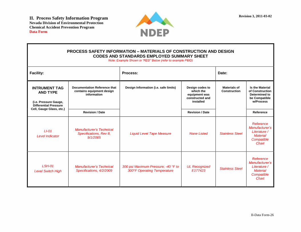
II-Data Form-26
PROCESS SAFETY INFORMATION – MATERIALS OF CONSTRUCTION AND DESIGN
CODES AND STANDARDS EMPLOYED SUMMARY SHEET Note: Example Shown in “RED” Below (refer to example P&ID)
Facility: Process: Date:
INTRUMENT TAG AND TYPE
(i.e. Pressure Gauge, Differential Pressure
Cell, Gauge Glass, etc.)
Documentation Reference that contains equipment design
information
Design Information (i.e. safe limits)
Design codes to which the
equipment was constructed and
installed
Materials of Construction
Is the Material of Construction Determined to be Compatible
w/Process
Revision / Date Revision / Date Reference
LI-01
Level Indicator
Manufacturer’s Technical Specifications, Rev 8,
9/1/2005 Liquid Level Tape Measure None Listed Stainless Steel
Reference Manufacturer’s
Literature / Material
Compatible Chart
LSH-01
Level Switch High
Manufacturer’s Technical Specifications, 4/2/2009
300 psi Maximum Pressure; -40 °F to 300°F Operating Temperature
UL Recognized E177423
Stainless Steel
Reference Manufacturer’s
Literature / Material
Compatible Chart

II. Process Safety Information Program Nevada Division of Environmental Protection
Chemical Accident Prevention Program
Data Form
Revision 3, 2011-03-02
II-Data Form-27
Piping and Valve Specifications
A pipe specification is a menu of pipe components of the right material and the right rating for a given service. The piping specification is an essential document in each project and at each plant because not only is it used for the initial design and procurement of materials, it will also be used throughout the life of the plant to choose and procure replacement parts, and to find out what is installed long after the system has been put in service. Because a piping specification is an important design document, it should be backed-up by a detailed report and calculations that explain how the materials, fittings and ratings were selected. The piping specification must be logically tied to the plant’s piping line numbers and the Piping & Instrumentation Diagrams (P&ID’s). Valves are not mentioned in the pipe specification, because the pipe specification will normally remain unchanged for the life of the system. The constant improvements in valve materials, design, fabrication, and performance result in continuous changes to valve models. [From the Piping and Pipeline Engineering, George A. Antaki, Marcel Dekker, Inc., 2003]

II. Process Safety Information Program Nevada Division of Environmental Protection
Chemical Accident Prevention Program
Data Form
Revision 3, 2011-03-02
II-Data Form-28
PROCESS SAFETY INFORMATION – PIPING SPECIFICATION LIST
Note: Example Shown in “RED” Below (refer to example P&ID)
Facility: Process: Date:
PIPING SPECIFICATION
Documentation Reference that contains equipment design
information
Design Information (i.e. safe limits)
Design codes to which the
equipment was constructed and installed (e.g. ASME
B31.3)
Materials of Construction
Is the Material of Construction Determined to be Compatible
w/Process
MA
WP
Te
mp
era
ture
Cla
ss
Sch
ed
ule
Co
rro
sio
n
All
ow
an
ce
Revision / Date (psi) (°F) # Sch. (inch) Revision / Date Reference
A1 SPEC01, Rev 10, 2/1/2011 740 psig
100
°F
300 lb.
80 1/16 inch
ASME B31.3 ASTM A106,
Grade B, Seamless
Reference Manufacturer’s
Literature / Material
Compatible Chart

II. Process Safety Information Program Nevada Division of Environmental Protection
Chemical Accident Prevention Program
Data Form
Revision 3, 2011-03-02
II-Data Form-29
PROCESS SAFETY INFORMATION – PIPING SPECIFICATION SUMMARY SHEET
Facility: Process: Date:
PIPING SPECIFICATION
Document Title Document No. Revision No. and/or Date
Does the Piping Specification include: Yes NA
Pipe specification number (or other identifier)?
Piping code (e.g., ASME B31.3) and year?
Service?
Design Pressure and Temperature?
Pressure class, i.e. based on the class of flange in the system?
Corrosion allowance?
Threaded Piping:
Size Range?
Pipe material and grade (e.g., ASTM A106, Grade B)?
Schedule (and calculations available to support this selection)?
Fittings (material, pressure rating, and dimensional standard)?

II. Process Safety Information Program Nevada Division of Environmental Protection
Chemical Accident Prevention Program
Data Form
Revision 3, 2011-03-02
II-Data Form-30
PROCESS SAFETY INFORMATION – PIPING SPECIFICATION SUMMARY SHEET (continued)
Does the Piping Specification include: Yes NA
Flanges, gaskets, and bolts?
Socket Welded Piping:
Size Range?
Pipe material and grade (e.g., ASTM A106, Grade B)?
Schedule (and calculations available to support this selection)?
Fittings (material, pressure rating, and dimensional standard)?
Flanges, gaskets, and bolts?
Butt Welded Piping:
Size Range?
Pipe material and grade (e.g., ASTM A106, Grade B)?
Schedule (and calculations available to support this selection)?
Fittings (material, pressure rating, and dimensional standard)?
Flanges, gaskets, and bolts?
Matrix of permitted branch connections?
Calculations to support the branch connections (where applicable)?

II. Process Safety Information Program Nevada Division of Environmental Protection
Chemical Accident Prevention Program
Data Form
Revision 3, 2011-03-02
II-Data Form-31
PROCESS SAFETY INFORMATION – VALVE SPECIFICATION LIST
Note: Example Shown in “RED” Below (refer to example P&ID)
Facility: Process: Date:
VALVE
SPECIFICATION
Documentation Reference that contains equipment design
information
Design Information (i.e. safe limits)
Design codes to which the
equipment was constructed and installed (e.g. API
600, ASME B16.34)
Materials of
Construction
Is the Material of Construction Determined to be Compatible
w/Process
MAWP
Temp.
Revision / Date (psi) (°F) Revision / Date Reference
V1
(includes HV-01 through HV-05)
SPEC02, Rev 11, 2/1/2011
3000 WOG
3000 psig
2500 psig
100 °F
300 °F
API 607 (certified fire test); ASME
B16.34; API 598; MSS SP-25; NACE
MR0103
Body and End Cap – A105
Stem and Ball – SS 630
Seat – PEEK
Reference Manufacturer’s
Literature / Material
Compatible Chart
II. Process Safety Information Program Nevada Division of Environmental Protection
Chemical Accident Prevention Program
Data Form
Revision 3, 2011-03-02
II-Data Form-32
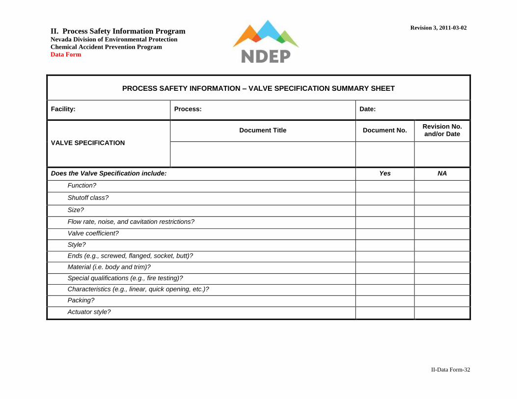
PROCESS SAFETY INFORMATION – VALVE SPECIFICATION SUMMARY SHEET
Facility: Process: Date:
VALVE SPECIFICATION
Document Title Document No. Revision No. and/or Date
Does the Valve Specification include: Yes NA
Function?
Shutoff class?
Size?
Flow rate, noise, and cavitation restrictions?
Valve coefficient?
Style?
Ends (e.g., screwed, flanged, socket, butt)?
Material (i.e. body and trim)?
Special qualifications (e.g., fire testing)?
Characteristics (e.g., linear, quick opening, etc.)?
Packing?
Actuator style?

II. Process Safety Information Program Nevada Division of Environmental Protection
Chemical Accident Prevention Program
Data Form
Revision 3, 2011-03-02
II-Data Form-33
Safe Upper and Lower Limits
Safe upper and lower limits define the maximum and minimum parameters that must not be exceeded. Exceeding these limits could result in a catastrophic failure. Knowledge of these limits is critical to enable adequate evaluation of consequences in the process hazard analysis. These limits could be either mechanical or process-related. Safe Mechanical limits are typically defined by codes, standards or equipment vendors and are applied to piping, equipment and instruments. Examples include design temperatures and pressures, often expressed as maximum allowable working pressure (MAWP) at a specified temperature. Another example would be upper and lower temperature limits that are defined by materials of construction. It must be noted that pressure and temperature limits are usually defined by coincident conditions (i.e. as temperature varies, the MAWP would vary). The minimum design temperature (a point often overlooked) is the lowest temperature the system is permitted to experience in service. It is important to keep in mind that each metal has a unique temperature below which the metal becomes brittle and can fracture. Safe Process limits may not be as well defined in literature as safe mechanical limits. These limits may be defined in industry publications or may require definition by the facility for their specific process.
For example, a safe process limit would be the oxidation-reduction potential (ORP) value in a manufactured sodium hypochlorite batch. Exceeding the safe upper ORP value, would result in release of chlorine gas from the solution (i.e. decomposition), which would be considered a catastrophic failure.
Safe process limits could be defined by variables such as the concentration of a reactant or the temperature of a chemical reaction. If exceeding a select limit would result in a catastrophic failure, that limit would be a safe limit. The process chemistry could be a starting point for development of some of the safe process limits.

II. Process Safety Information Program Nevada Division of Environmental Protection
Chemical Accident Prevention Program
Data Form
Revision 3, 2011-03-02
II-Data Form-34
Applying Safe Upper and Lower Limits
The safe upper and lower limits must be known for all piping, equipment and instruments. Additionally, any relevant safe limits as applied to process variables must be known. To identify the safe limits, identify the weakest components in the process. Keep in mind “a chain is only as strong as its weakest link.”
For example, if the piping system has the narrowest range of allowable pressure and temperature and all equipment and instrumentation within that piping system is capable of operating outside the allowable piping pressure and temperatures, then the safe limits are defined by the piping system. In this case, the safe upper and lower limits would be the limits of the piping system. The limits of the piping system would render the broader limits of the other system components irrelevant since the piping would fail first. When evaluating this system through the process hazard analysis, any deviation that would result in a pressure or temperature outside the piping system limits would indicate that a safe limit had been exceeded, hence prompting the need to implement some type of safeguard or mitigation measure. For example, in a cryogenic system, the piping may be rated to the minimum temperatures expected; then the vessels may determine the safe temperature lower limit. Additionally, in a process where a vacuum could be created; again the piping may be rated for this pressure, but the vessels may not be. Therefore, the vessels would establish the safe pressure lower limit.

II. Process Safety Information Program Nevada Division of Environmental Protection
Chemical Accident Prevention Program
Data Form
Revision 3, 2011-03-02
II-Data Form-35
Determining the Extent of
Safe Upper and Lower Limits
Once the safe limits for each component are defined, the safe limits should be defined for a process segment (process or a specific section of a process); rather than for each component. Process segments may also correspond to process hazard analysis nodes.
For example, in a pumped liquid system, the process could conceivably be split into two sections or process segments; the pump suction section and the pump discharge section. Evaluation of the design limits for piping, equipment and instruments in each of the process segments could then proceed as noted above. The weakest component in each section would then be used to define the safe limits for that section.
Determining the
Appropriate Variables for Safe Limits
There is no prescribed number of variables for which safe limits must be defined.

II. Process Safety Information Program Nevada Division of Environmental Protection
Chemical Accident Prevention Program
Data Form
Revision 3, 2011-03-02
II-Data Form-36
Evaluation of the Consequence of Deviation
from the Safe Limits
Understanding how the consequence of deviation from a safe limit is applied in the process hazard analysis helps to explain how the consequence is defined. The consequence of deviation from a safe mechanical limit is typically some type of component failure, coupled with the consequence of both the component failure and the hazardous substance release. For example, the consequence of exceeding the upper pressure limit in a process where a pressure vessel is the limiting factor would be vessel rupture along with the associated personnel impacts and other onsite and offsite impacts. The consequence in this case would not be pressure relief valve discharge. The pressure relief valve is a safeguard that is intended to prevent the safe limit from being exceeded. In a process hazard analysis, this consequence would be ranked very severe. The presence of an appropriately sized and maintained pressure relief valve would make the likelihood of the severe consequence occurring very remote, hence, minimizing the overall risk. Assigning the appropriate consequence helps to ensure that any existing or proposed safeguard is adequately scrutinized. The consequence of deviation from a safe process limit must be thoroughly defined as with safe mechanical limits. The consequence must not only describe the direct result of the deviation, such as chlorine release to atmosphere in the example of the oxidation-reduction potential (ORP), but must also describe the associated personnel impacts and other onsite and offsite impacts.
II. Process Safety Information Program Nevada Division of Environmental Protection
Chemical Accident Prevention Program
Data Form
Revision 3, 2011-03-02
II-Data Form-37
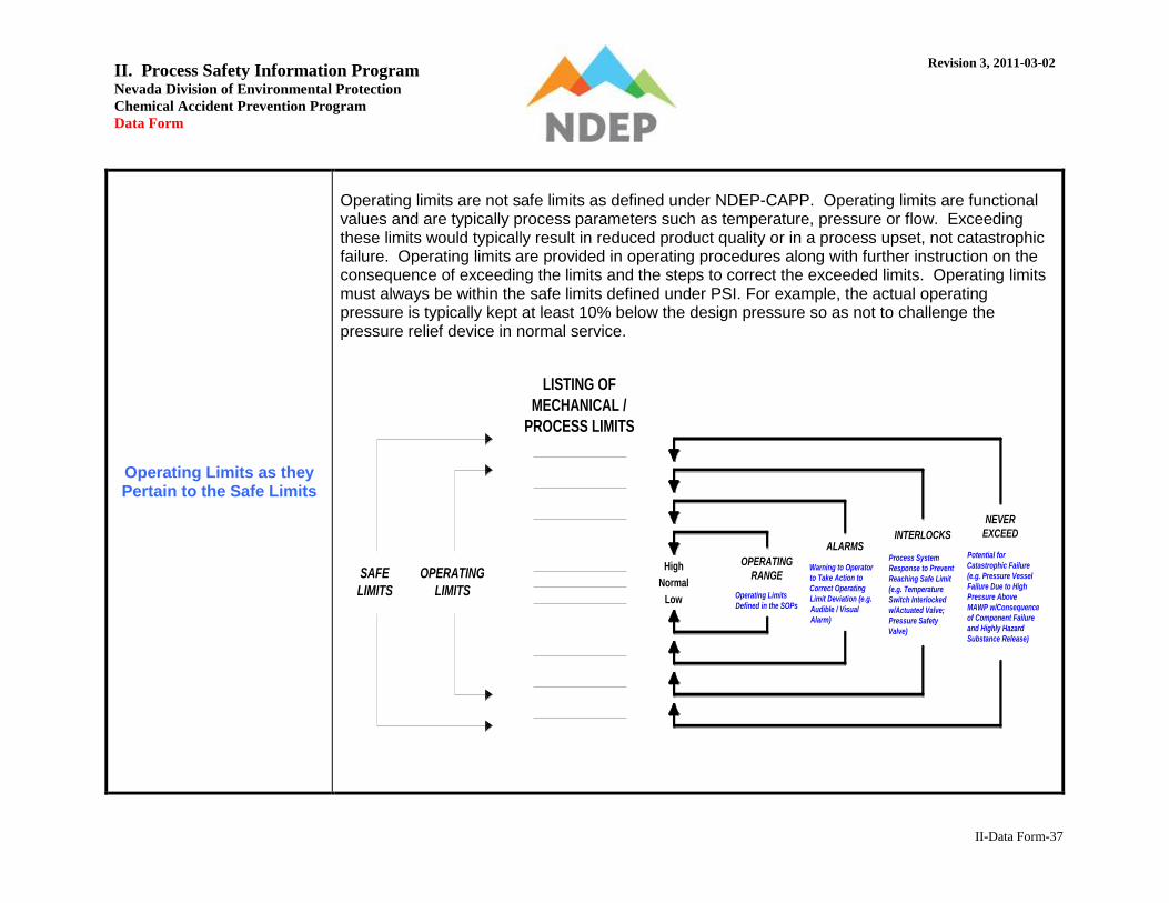
Operating Limits as they Pertain to the Safe Limits
Operating limits are not safe limits as defined under NDEP-CAPP. Operating limits are functional values and are typically process parameters such as temperature, pressure or flow. Exceeding these limits would typically result in reduced product quality or in a process upset, not catastrophic failure. Operating limits are provided in operating procedures along with further instruction on the consequence of exceeding the limits and the steps to correct the exceeded limits. Operating limits must always be within the safe limits defined under PSI. For example, the actual operating pressure is typically kept at least 10% below the design pressure so as not to challenge the pressure relief device in normal service.
Normal
High
Low
OPERATING
RANGE
ALARMS
NEVER
EXCEEDINTERLOCKS
LISTING OF
MECHANICAL /
PROCESS LIMITS
OPERATING
LIMITS
SAFE
LIMITS Operating Limits
Defined in the SOPs
Warning to Operator
to Take Action to
Correct Operating
Limit Deviation (e.g.
Audible / Visual
Alarm)
Potential for
Catastrophic Failure
(e.g. Pressure Vessel
Failure Due to High
Pressure Above
MAWP w/Consequence
of Component Failure
and Highly Hazard
Substance Release)
Process System
Response to Prevent
Reaching Safe Limit
(e.g. Temperature
Switch Interlocked
w/Actuated Valve;
Pressure Safety
Valve)

II. Process Safety Information Program Nevada Division of Environmental Protection
Chemical Accident Prevention Program
Data Form
Revision 3, 2011-03-02
II-Data Form-38
PROCESS SAFETY INFORMATION – SAFE UPPER AND LOWER LIMITS SUMMARY SHEET
Notes to Table: Repeat table for each process segment; additionally, it may be appropriate to complete the information required in Section 4 prior to completing this table.
Note: Example Shown in “RED” Below (refer to example P&ID)
Facility: Process: Date:
Process Segment (Once the Safe Limits for Each Component are Defined (see “Information Related to the Equipment of the Process”, Section 4 Below), the Safe Limits Should be Defined for Specific Sections of a Process (rather than for each component):
Liquid Knockout Pot to Reciprocating Compressor Suction
SAFE UPPER AND LOWER LIMITS (Including Evaluation of the Consequence of Deviation from Safe Limits) The document(s) listed in this section
refer to where the facility has documented the safe upper and lower limits for each process segment (e.g., P&IDs, Table of Safe Limits)
Document Title Document No. Revision No. and/or Date
Piping and Instrument Diagram PID0001 Rev 3, 2/3/2004

II. Process Safety Information Program Nevada Division of Environmental Protection
Chemical Accident Prevention Program
Data Form
Revision 3, 2011-03-02
II-Data Form-39
PROCESS SAFETY INFORMATION – SAFE UPPER AND LOWER LIMITS SUMMARY SHEET (continued)
Notes to Table: Repeat table for each process segment; additionally, it may be appropriate to complete the information required in Section 4 prior to completing this table.
Note: Example Shown in “RED” Below (refer to example P&ID)
Equipment
Note: Equipment that Defines the Safe Limit (e.g. “The Weakest Link”)
Variable
Safe Limit
Note: Refer to Section 4 for some Mechanical Safe
Limits
Consequence of Deviation
(e.g. Vessel Rupture)
LSH-01
Pressure
Upper 300 psi Potential Failure of Instrument and Release of Highly
Hazardous Substance
PV-01 Lower Vacuum Potential for RC-01 to Create Vacuum at PV-01 and Collapse of PV-01 (is PV-01 rated for full vacuum?)
RC-01 Temperature
Upper 100 °F Maximum Operating Temperature of RC-01; Potential
Failure of RC-01 (consult manufacturer)
Piping Specification A1 Lower -20 °F Impact Testing Required per B31.3
NA
Flow
Upper NA NA
RC-01 Lower 4 CFM @ 400 RPM Inadequate Flow of Material to RC-01; Potential Failure of
RC-01 (consult manufacturer)
PV-01 Level
Upper 52 inches Potential Overfill of PV-01 and Liquid to RC-01; Potential
Catastrophic Failure of RC-01 and Release
NA Lower NA NA
NA Stream Composition NA NA
PV-01; Piping Specification A1 Corrosion Allowance 1/16 inch Potential Reduction in Wall Thickness and Failure of PV-
01 or Piping
NA Vibration
Upper NA NA
NA Lower NA NA
NA Other NA NA

II. Process Safety Information Program Nevada Division of Environmental Protection
Chemical Accident Prevention Program
Data Form
Revision 3, 2011-03-02
II-Data Form-40
Electrical Classification
An electrical classified area is a location where flammable gases or vapors, flammable liquids, or combustible liquids are processed or handled; and where their release into the atmosphere could result in their ignition by electrical systems or equipment.
PROCESS SAFETY INFORMATION – ELECTRICAL CLASSIFIED AREA SUMMARY SHEET
Facility: Process: Date:
ELECTRICAL CLASSIFIED AREA
Document Title Reference Standard
(e.g., Article 500 of NEC) Revision No. and/or Date
Does the Electrical Classified Area Evaluation include: Yes NA
Distinguish between electrically classified and unclassified areas?
Elevations to distinguish between electrically unclassified and classified areas?
Has the Facility: Yes NA
Evaluated installed components and equipment within classified area?
How was this documented?
Evaluate control rooms and other buildings within the classified area?
How was this documented?
II. Process Safety Information Program Nevada Division of Environmental Protection
Chemical Accident Prevention Program
Data Form
Revision 3, 2011-03-02
II-Data Form-41
Pressure Relief Devices
Pressure relief devices are used to protect pressure vessel or equipment from exceeding the design pressure. A pressure relief device is actuated by inlet static pressure and is designed to open during emergency or abnormal conditions to prevent a rise of internal fluid pressure in excess of a specified value. The device may also be designed to prevent excessive internal vacuum.
PROCESS SAFETY INFORMATION – PRESSURE RELIEF DEVICES LIST

II. Process Safety Information Program Nevada Division of Environmental Protection
Chemical Accident Prevention Program
Data Form
Revision 3, 2011-03-02
II-Data Form-42
Facility: Process: Date:
PRESSURE RELIEF DEVICE
AND TYPE
Calculation Document
Title, Revision No. and/or Date
Sizing Basis (e.g., fire, process upset,
thermal)
Calculated Requirement
Actual Nameplate
Set Pressure @ Temperature
Capacity
Accumulation
Set Pressure @ Temperature
Capacity
Accumulation
(psi @ °F) (scfm) (%) (psi @ °F) (scfm) (%)
Has the capacity of pressure relief headers and associated flares been evaluated for required capacity; and has the actual capacity been determined adequate?
Yes
N/A

II. Process Safety Information Program Nevada Division of Environmental Protection
Chemical Accident Prevention Program
Data Form
Revision 3, 2011-03-02
II-Data Form-43
Ventilation System
A ventilation system may be required by code due to the presence of a hazardous substance inside a building.
PROCESS SAFETY INFORMATION – VENTILATION SUMMARY SHEET
Facility: Process: Date:
VENTILATION SYSTEM
Document Title Uniform Fire Code (Article
80) or other Nationally Recognized Standard
Revision No. and/or Date
Does the Ventilation System include: Yes NA
Capacity calculations required by the applicable code or standard?
Confirmation that the system provides the required capacity?
Evaluation that system configuration is adequate?
Has the capacity of scrubbers been evaluated for required capacity; and has the actual capacity been determined adequate?
Yes
N/A

II. Process Safety Information Program Nevada Division of Environmental Protection
Chemical Accident Prevention Program
Data Form
Revision 3, 2011-03-02
II-Data Form-44
Material and Energy Balance
Material quantities, as they pass through processing operations, can be described by material balances. Such balances are statements of the conservation of mass. Similarly, energy quantities can be described by energy balances, which are statements of the conservation of energy. If there is no accumulation, what goes into a process must come out. This is true for batch operations. It is equally true for continuous operation over any chosen time interval. Balances are fundamental to process control. See “Process Flow Diagram” section above
PROCESS SAFETY INFORMATION – MATERIAL AND ENERGY BALANCE SUMMARY SHEET
Facility: Process: Date:
MATERIAL AND ENERGY BALANCE
Document Title Revision No. and/or Date
Does the Material and Energy Balance include: Yes NA
Cover each part of the process represented on the process flow diagram?
Stream data around each major piece of equipment?
Stream data around each process-altering control system?

II. Process Safety Information Program Nevada Division of Environmental Protection
Chemical Accident Prevention Program
Data Form
Revision 3, 2011-03-02
II-Data Form-45
PROCESS SAFETY INFORMATION – MATERIAL AND ENERGY BALANCE SUMMARY SHEET (continued)
Does the Material and Energy Balance include: Yes NA
Stream variables:
Pressure?
Temperature?
Flow?
Density?
Molecular weight?
Enthalpy?
Phase
Composition?

II. Process Safety Information Program Nevada Division of Environmental Protection
Chemical Accident Prevention Program
Data Form
Revision 3, 2011-03-02
II-Data Form-46
Section 5. Description of Safety Systems and Their Functions
Safety System Description
The safety system description should provide a brief description and overview of the function of all safety systems that are present at the facility.
PROCESS SAFETY INFORMATION – SAFETY SYSTEM DESCRIPTION SUMMARY SHEET
Facility: Process: Date:
SAFETY SYSTEM DESCRIPTION
Document Title Revision No. and/or Date
Does the Safety System Description include: Yes NA
Emergency shut-down system?
Toxic gas sensors?
Combustible gas sensors?
Flame Detectors?
Firewater System?

II. Process Safety Information Program Nevada Division of Environmental Protection
Chemical Accident Prevention Program
Data Form
Revision 3, 2011-03-02
II-Data Form-47

II. Process Safety Information Program Nevada Division of Environmental Protection
Chemical Accident Prevention Program
Data Form
Revision 3, 2011-03-02
II-Data Form-48
PROCESS SAFETY INFORMATION – SAFETY SYSTEM DESCRIPTION SUMMARY SHEET (continued)
Does the Safety System Description include: Yes NA
Emergency generator?
Uninterruptible power supply (UPS)?
Flare system?
Incinerator?
Vent scrubber?
Audible and visual alarms?
Other?

II. Process Safety Information Program Nevada Division of Environmental Protection
Chemical Accident Prevention Program
Data Form
Revision 3, 2011-03-02
II-Data Form-49
Section 6. Management Plan and Document Control
Management Plan and Document Control
The process safety information procedure should answer the questions of who, what, when, where, and how of PSI compilation specific to the facility.

II. Process Safety Information Program Nevada Division of Environmental Protection
Chemical Accident Prevention Program
Data Form
Revision 3, 2011-03-02
II-Data Form-50
Section 7. Evaluation of Code Applicability and Compliance
Codes, Standards and Good Engineering
Practices
Building structures, structural steel, and foundations are typically evaluated by local building codes, that are enforced by the appropriate state, county or municipal agency. The facility must obtain permits to construct and occupy the process (and associated buildings) as required by the jurisdiction they are located in. Not all design and construction codes that apply to a process regulated under NDEP-CAPP have been adopted by local building officials. NDEP-CAPP requires the regulated facility to design and construct in accordance with applicable codes and standards, or best engineering practices. While compliance with these codes or engineering practices may not be mandatory per local building officials, they become mandatory under NDEP-CAPP, and full compliance is required. The correct list of applicable codes and standards vary, based upon the type of process and the industry. The list below denotes codes and standards that may apply to the process. While it is not comprehensive, it does present a significant number of codes and standards that could apply. Actual definition of applicable codes and standards is the responsibility of the facility, as is compliance confirmation. Design and construction codes for equipment, piping and material specifications have been addressed in Section 4 of this Data Form.
For example, pressure vessels (MAWP > 15 psi) would be addressed under ASME Boiler and Pressure Vessel Code (B&PV), Section VIII For example, piping could be covered under ASME B31.3 For example, ping leak testing could be covered under ASME B31.3, Section VI

II. Process Safety Information Program Nevada Division of Environmental Protection
Chemical Accident Prevention Program
Data Form
Revision 3, 2011-03-02
II-Data Form-51
Codes, Standards and Good Engineering
Practices (continued)
For example, piping materials could be covered under ASTM A106 For example, pipe hangers and supports could be covered under MSS SP-58
Electrical Classification has been addressed in Section 4 of this Data Form.
For example, electrical classification could be covered under NFPA 497
Pressure Safety Valves (relief devices) have been addressed in Section 4 of this Data Form.
For example, relief devices could be covered under API Recommended Practice 520 / 521 Ventilation System has been addressed in Section 4 of this Data Form.
For example, the ventilation system could be covered under IIAR Bulletin 111 Codes, Standards and Good Engineering Practices that have not been addressed in this Data Form, up to this point, are those that generally address installation, operations, and maintenance from an industry practice perspective. Some examples:
NFPA 59A: Standard for the Production, Storage, and Handling of Liquefied Natural Gas (LNG)
Chlorine Institute Pamphlet 17: Packaging Plant Safety and Operational Guidelines
IIAR Bulletin 110 - Guidelines for: Start-Up, Inspection and Maintenance of Ammonia Mechanical Refrigerating Systems
II. Process Safety Information Program Nevada Division of Environmental Protection
Chemical Accident Prevention Program
Data Form
Revision 3, 2011-03-02
II-Data Form-52
Codes, Standards and Good Engineering
Practices (continued)
Once applicable codes and specifications have been defined, compliance with those codes and specifications must be evaluated. In general, the process must be in compliance with the version of the code in place at the time of construction, unless dictated otherwise by authorities having jurisdiction. Although not mandatory, differences between current code versions and the version in place at the time of construction should be understood. As an additional hazard identification step, the process should be reviewed to determine compliance with the current code version, and if not in compliance, determine if any additional hazards exist. The facility should then implement further safeguards or mitigation measures as warranted by the code deficiency.

II. Process Safety Information Program Nevada Division of Environmental Protection
Chemical Accident Prevention Program
Data Form
Revision 3, 2011-03-02
II-Data Form-53
PROCESS SAFETY INFORMATION – CODES, STANDARDS AND GOOD ENGINEERING PRACTICE
SUMMARY SHEET
Facility: Process: Date:
Has the Facility evaluated: Yes NA
Required building permits for construction and occupancy of the process?
List Building Permits (including date and applicable codes):
Applicable codes, standards and good engineering practices?
List Industry Practices (including date and applicable publication):