Embed Size (px)
Citation preview

Process Simulation of Sheet Molding Compound in the Context of a Virtual Process Chain
3DEXPERIENCE Conference – Design, Modeling and Simulation| Nov. 19 – 21, 2019Dr.-Ing. Martin Hohberg
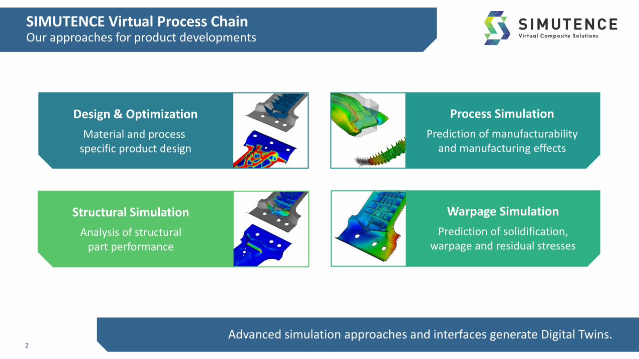
SIMUTENCE Virtual Process ChainOur approaches for product developments
2Advanced simulation approaches and interfaces generate Digital Twins.
Design & Optimization
Material and process specific product design
Process Simulation
Prediction of manufacturabilityand manufacturing effects
Warpage Simulation
Prediction of solidification,warpage and residual stresses
Structural Simulation
Analysis of structuralpart performance

Agenda
• Introduction and Motivation
• Modelling Approaches
• Application and Validation
• Process Simulation with SimuFill
• Mapping with SimuChain
• Structural Simulation
• Conclusion and Outlook
3
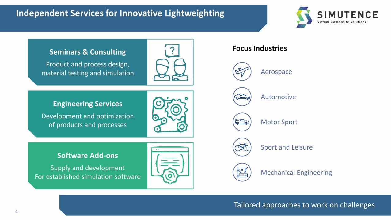
Independent Services for Innovative Lightweighting
4Tailored approaches to work on challenges
Seminars & Consulting
Product and process design,material testing and simulation
Engineering Services
Development and optimizationof products and processes
Software Add-ons
Supply and developmentFor established simulation software
Aerospace
Mechanical Engineering
Motor Sport
Automotive
Sport and Leisure
Focus Industries
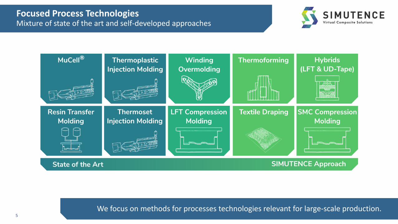
Focused Process TechnologiesMixture of state of the art and self-developed approaches
5We focus on methods for processes technologies relevant for large-scale production.

Sheet Molding CompoundMaterial and Process
• Wildly used in the automotive industry due to high formability and low costs
• New application in semi-structural applications
• High volume production with constant growth
• Best for Class-A and semi-structural lightweight parts
6
• Preimpregnated composite material
• 25 vol.% copped fibers (1 inch, 25 mm)
• 25 vol.% resin
• 50 vol.% fillers
• Separate manufacturing of material and part
• Compression molding process
Matured SMC prepreg material [1] SMC initial charge placed in the tool [2]
C-pillarMass transit Automotive
[3] [4] [5]

Agenda
• Introduction and Motivation
• Modelling Approaches
• Application and Validation
• Process Simulation with SimuFill
• Mapping with SimuChain
• Structural Simulation
• Conclusion and Outlook
7
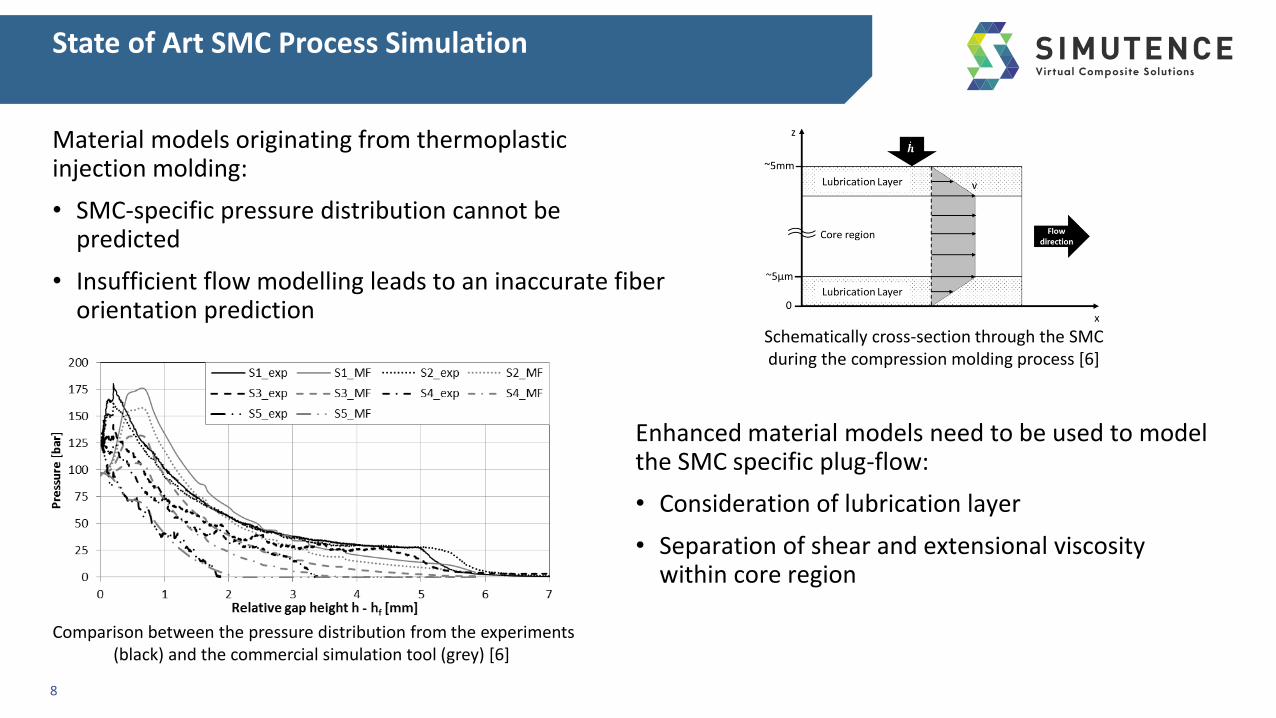
State of Art SMC Process Simulation
Material models originating from thermoplastic injection molding:
• SMC-specific pressure distribution cannot be predicted
• Insufficient flow modelling leads to an inaccurate fiber orientation prediction
8
Comparison between the pressure distribution from the experiments (black) and the commercial simulation tool (grey) [6]
Schematically cross-section through the SMC during the compression molding process [6]
Enhanced material models need to be used to model the SMC specific plug-flow:
• Consideration of lubrication layer
• Separation of shear and extensional viscosity within core region
Basic Modelling Approach
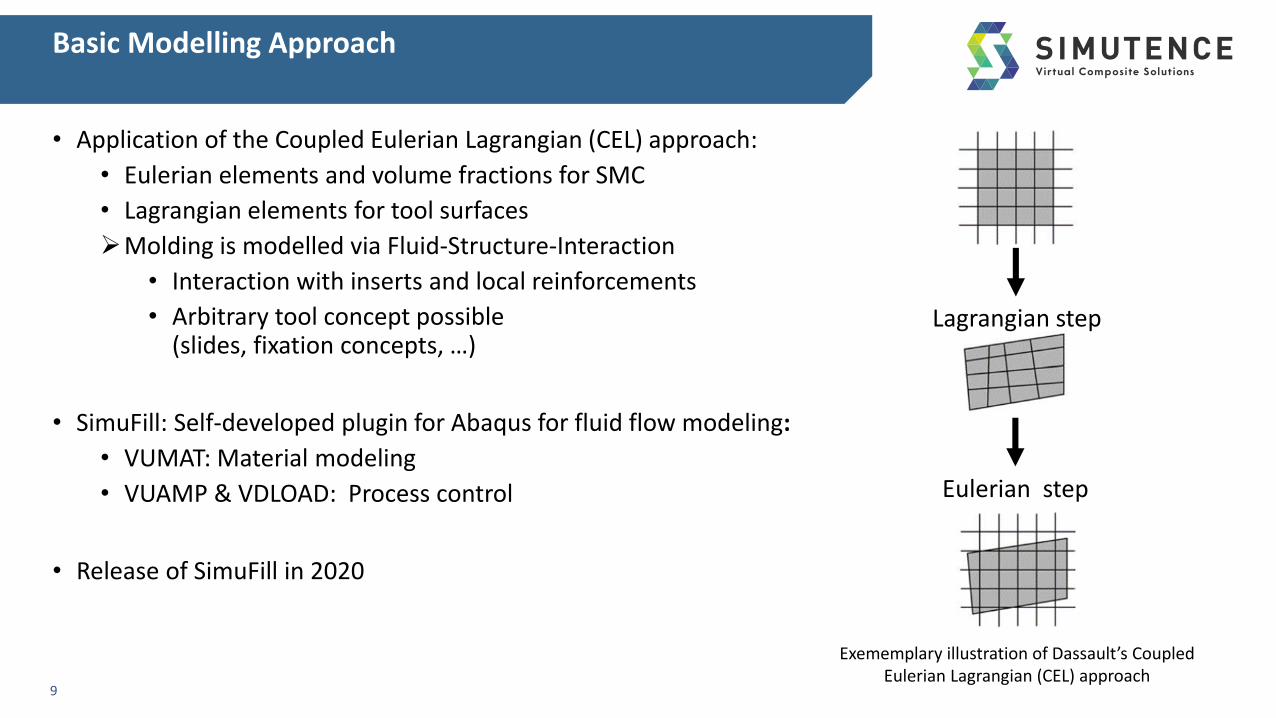
• Application of the Coupled Eulerian Lagrangian (CEL) approach:
• Eulerian elements and volume fractions for SMC
• Lagrangian elements for tool surfaces
Molding is modelled via Fluid-Structure-Interaction
• Interaction with inserts and local reinforcements
• Arbitrary tool concept possible (slides, fixation concepts, …)
• SimuFill: Self-developed plugin for Abaqus for fluid flow modeling:
• VUMAT: Material modeling
• VUAMP & VDLOAD: Process control
• Release of SimuFill in 2020
9
Lagrangian step
Eulerian step
Exememplary illustration of Dassault’s CoupledEulerian Lagrangian (CEL) approach

Material Modelling
• Basic approach:
• Superposition of hydrostatic, rheological and frictional stress, since lubrication layer is to small to be discretized
: Rheological stress within the core region
: Friction stress within the core region
: Hydrostatic pressure within the core region
• Hydrostatic pressure is based on a hyperelastic incompressible material formulation:
10
𝝈 = −𝑝𝑰 + 𝝈rheo + 𝜮fric
Modelling approach of the stress distribution during the compression molding process
Schematically cross-section through the SMC during the compression molding process
𝝈rheo
𝜮fric
𝑝 =𝐾
2ln det 𝑭 𝒃−1 𝒃 = 𝑭 ∙ 𝑭𝑇
𝑝

Material and Fiber Orientation Modelling
• Lubrication model is based on a hydrodynamic friction formulation:
• Separation of shear 𝜂shear and elongational viscosity 𝜂ext for the core region:
• Prediction of fiber reorientation:
• Application of the ARD-RSC model
• IBOF closure approximation
11
Modelling approach of the stress distribution during the compression molding process
𝜮fric = −𝜆Ԧ𝑣
𝑣0
𝑚−1
Ԧ𝑣 ⊗ 𝑛
𝝈rheo = 𝜂ext 𝑫⊗ 𝑰 + 𝜂shear ሶ𝜸
Schematically cross-section through the SMC during the compression molding process

Agenda
• Introduction and Motivation
• Modelling Approaches
• Application and Validation
• Process Simulation with SimuFill
• Mapping with SimuChain
• Structural Simulation
• Conclusion and Outlook
12

Application and ValidationStructure and Load Cases
13
• Lid structure
• Two configuration were manufactured:
• Plane SMC configuration
• Reinforced configuration with UD patches
• Manufactured in a large tool and then cutting to nominal size
• Load Case: 4-Point bending4-Point Bending setup [7]
Lid part with local unidirectional reinforcementsLid part out of SMC

Application and ValidationModel Setup
14
• Tool surfaces:
• Rigid bodies
• Mold closing profile as velocity BC
• Cavity:
• Eulerian elements
• BC used to avoid flow over the sides
• Initial Charge
• Application of a preformed configuration to reduce calculation time
• Mapping of fiber orientations from forming to compression molding simulation
Model setup with initial charge positioning (top) and tool surfaces (bottom)

Application and ValidationResults and Validation
15
• Comparison of fiber orientation distribution:
• CT-Scan
• SimuFill and state-of-art simulation tool
• SimuFill shows better results with the same fiber interaction coefficients
Advanced flow modelling is crucial for accurate fiber orientation prediction for SMC
Fiber orientation tensor components along the cross section [7] Process simulation of lid structure

Application and ValidationSimuChain
16
• Homogenization within Abaqus CAE
• Assessable via GUI or within command line
• Basis module offers linear-elastic thermo-mechanical homogenization
• Customizable for user specific material card creation
• SimuChain enables to transfer process effects from process simulation to structural simulation• Abaqus CAE plugin
• Mapping w. MPCCI MapLib from Fraunhofer SCAI
• Release SimuChain in 2020
Screenshot from SimuChain for import of fiber orientation distribution from injection molding simulation
Screenshot from SimuChain for homogenization of effective material properties for short/long fiber-reinforced plastics
Application and ValidationEffects on Structural Simulation
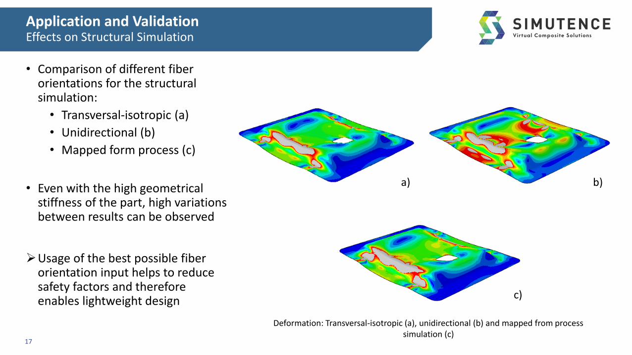
• Comparison of different fiber orientations for the structural simulation:
• Transversal-isotropic (a)
• Unidirectional (b)
• Mapped form process (c)
• Even with the high geometrical stiffness of the part, high variations between results can be observed
Usage of the best possible fiber orientation input helps to reduce safety factors and therefore enables lightweight design
17
Deformation: Transversal-isotropic (a), unidirectional (b) and mapped from process simulation (c)
a) b)
c)

Agenda
• Introduction and Motivation
• Modelling Approaches
• Application and Validation
• Process Simulation with SimuFill
• Mapping with SimuChain
• Structural Simulation
• Conclusion and Outlook
18
Conclusion and Outlook
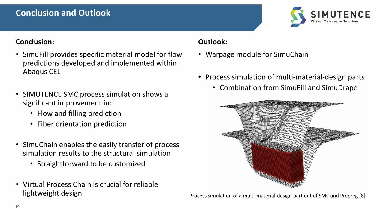
Conclusion:
• SimuFill provides specific material model for flow predictions developed and implemented within Abaqus CEL
• SIMUTENCE SMC process simulation shows a significant improvement in:
• Flow and filling prediction
• Fiber orientation prediction
• SimuChain enables the easily transfer of process simulation results to the structural simulation
• Straightforward to be customized
• Virtual Process Chain is crucial for reliable lightweight design
Outlook:
• Warpage module for SimuChain
• Process simulation of multi-material-design parts
• Combination from SimuFill and SimuDrape
19
Process simulation of a multi-material-design part out of SMC and Prepreg [8]

References
20
[1]: Indiamart; https://www.indiamart.com/proddetail/sheet-moulding-compounds-4041892012.html
[2]: PhD Thesis D. Bücheler: Locally Continuous-fiber Reinforced Sheet Molding Compound
[3]: Design for success-A design & technology manual for SMC BMC, the European Alliance for SMC BMC
[4]: Alfa Romeo, https://www.simonstonemotorgroup.co.uk/alfa-romeo/new-car-configurator?pageId=466490
[5]: Composites World, https://d2n4wb9orp1vta.cloudfront.net/cms/1116CW_PlantTour_Fig4.jpg;width=860;quality=80
[6]: PhD Thesis M. Hohberg: Experimental investigation and process simulation of the compression molding process of Sheet Molding Compound (SMC) with local reinforcements
[7]: Görthofer et al.: Virtual process chain of sheet molding compound: Development, validation and perspectives
[8]: Internal result from N. Meyer (KIT)

Dr.-Ing. Martin HohbergMobile: +49 (0)176-34652895Phone: +49 (0)[email protected]
Rintheimer Querallee 276131 Karlsruhe, Germany
Thank you for your Attention!
Co
nta
ctContact Data


![INTEGRATED NUMERICAL SIMULATION OF INJECTION MOLDING … · injection molding filling simulation [8]. Numerical experiments confirm the reliability and efficiency of the solver. Integrated](https://img.pdfslide.net/doc/110x75/5d0d0f7388c993ed388b4830/integrated-numerical-simulation-of-injection-molding-injection-molding-filling.jpg)