Embed Size (px)
Citation preview
873
29Processing Thermoplastics Urethanes via Twin Screw Extrusion
Charlie Martin
29.1 Introduction
Twin screw extruders (TSEs) are used to process virtually every type of plastic that is used today. The goal of this chapter is to define how twin screw extrusion (TSEs) can be used to process thermoplastic polyurethane (TPU) formulations that contain additive and fillers into pellets and shapes. Some simple formulas are interspersed with the text to provide insight into how TSEs are designed and the advantages of using TSEs for the synthesis, processing, and compounding of thermoplastic urethanes.
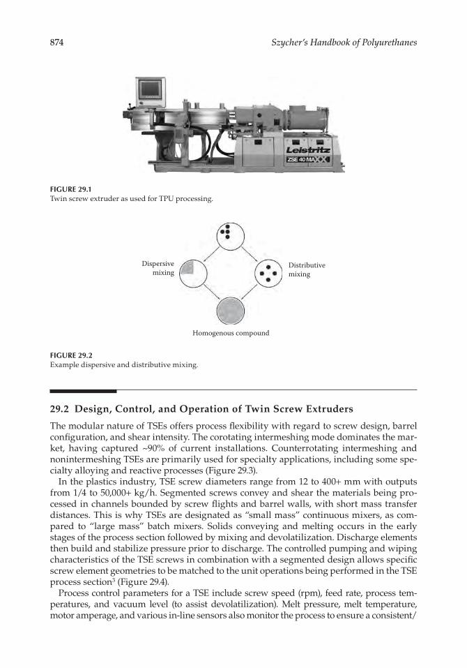
High-speed, energy-input (HSEI) corotating and counterrotating twin screw extruders are mass transfer devices that are the industry’s preferred manufacturing methodology for compounding, devolatilization, reactive extrusion, and blending. Materials that are typically compounded include fillers, colors, fibers, nanoparticles, lubricants, and stabi-lizers, as well as an infinite number of process aids and specialty additives. TPUs are also alloyed with other polymers, including with polypropylene as a PVC replacement.1 Reactive extrusion is also possible. Each formulation requires its own system configura-tion and processing conditions. However, some generalities can be stated, for instance, TPUs can be easily overworked and degraded, which necessitates gentler TSE configura-tions and processing conditions as compared to most other polymers (Figure 29.1).
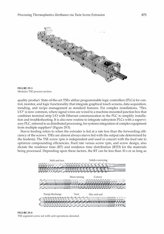
TSEs perform dispersive and distributive mixing. In dispersive mixing, solid agglomer-ates or liquid droplets held together by interfacial tension are subjected to mechanical stress for size reduction. The most important flow characteristics for dispersive mixing efficiency are the shear stresses associated with the extensional and planar flow fields as generated by TSE screw mixing elements. In distributive mixing, repeated rearrangement of the minor components without destructuring size enhances product homogeneity2 (Figure 29.2).
ConTEnTS
29.1 Introduction ........................................................................................................................ 87329.2 Design, Control, and Operation of Twin Screw Extruders .......................................... 87429.3 TSE Process Section: The “Key” to Success ....................................................................88029.4 Downstream Systems ........................................................................................................ 88929.5 Examples of TPU Processes Performed on Twin Screw Extrusion Systems ............. 89329.6 Summary ............................................................................................................................. 896References ..................................................................................................................................... 896
874 Szycher’s Handbook of Polyurethanes
29.2 Design, Control, and operation of Twin Screw Extruders
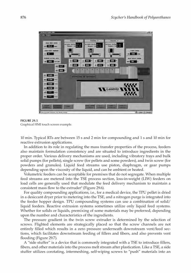
The modular nature of TSEs offers process flexibility with regard to screw design, barrel configuration, and shear intensity. The corotating intermeshing mode dominates the mar-ket, having captured ~90% of current installations. Counterrotating intermeshing and nonintermeshing TSEs are primarily used for specialty applications, including some spe-cialty alloying and reactive processes (Figure 29.3).
In the plastics industry, TSE screw diameters range from 12 to 400+ mm with outputs from 1/4 to 50,000+ kg/h. Segmented screws convey and shear the materials being pro-cessed in channels bounded by screw flights and barrel walls, with short mass transfer distances. This is why TSEs are designated as “small mass” continuous mixers, as com-pared to “large mass” batch mixers. Solids conveying and melting occurs in the early stages of the process section followed by mixing and devolatilization. Discharge elements then build and stabilize pressure prior to discharge. The controlled pumping and wiping characteristics of the TSE screws in combination with a segmented design allows specific screw element geometries to be matched to the unit operations being performed in the TSE process section3 (Figure 29.4).
Process control parameters for a TSE include screw speed (rpm), feed rate, process tem-peratures, and vacuum level (to assist devolatilization). Melt pressure, melt temperature, motor amperage, and various in-line sensors also monitor the process to ensure a consistent/
Distributivemixing
Homogenous compound
Dispersivemixing
Figure 29.2Example dispersive and distributive mixing.
Figure 29.1Twin screw extruder as used for TPU processing.
875Processing Thermoplastics Urethanes via Twin Screw Extrusion
quality product. State-of-the-art TSEs utilize programmable logic controllers (PLCs) for con-trol, monitor, and logic functionality that integrate graphical touch screens, data acquisition, trending, and recipe management as standard features. For complex installations, “Flex I/O” is now common, where signal wires are wired to a machine-mounted junction box that combines terminal strip I/O with Ethernet communication to the PLC to simplify installa-tion and troubleshooting. It is also now routine to integrate subsystem PLCs with a supervi-sory PLC, referred to as distributed processing, for systems integration of complex equipment from multiple suppliers4 (Figure 29.5).
Starve feeding refers to when the extruder is fed at a rate less than the forwarding effi-ciency of the screws. TSEs are almost always starve fed with the output rate determined by the feeder(s). The TSE screw rpm is independent and used in concert with the feed rate to optimize compounding efficiencies. Feed rate versus screw rpm, and screw design, also dictate the residence time (RT) and residence time distribution (RTD) for the materials being processed. Depending upon these factors, the RT can be less than 10 s or as long as
Figure 29.3Modular TSE process section.
Melt and mix
Mix and seal
Solids conveying
More mixing
Pump/discharge Vent
Convey
Figure 29.4TSE segment screw set with unit operations denoted.
876 Szycher’s Handbook of Polyurethanes
10 min. Typical RTs are between 15 s and 2 min for compounding and 1 s and 10 min for reactive extrusion applications.
In addition to its role in regulating the mass transfer properties of the process, feeders also maintain formulation consistency and are situated to introduce ingredients in the proper order. Various delivery mechanisms are used, including vibratory trays and bulk solid pumps (for pellets), single screw (for pellets and some powders), and twin screw (for powders and granules). Liquid feed streams use piston, diaphragm, or gear pumps depending upon the viscosity of the liquid, and can be ambient or heated.
Volumetric feeders can be acceptable for premixes that do not segregate. When multiple feed streams are metered into the TSE process section, loss-in-weight (LIW) feeders on load cells are generally used that modulate the feed delivery mechanism to maintain a consistent mass flow to the extruder3 (Figure 29.6).
For quality compounding applications, i.e., for a medical device, the TPU pellet is dried in a desiccant dryer prior to metering into the TSE, and a nitrogen purge is integrated into the feeder hopper design. TPU compounding systems can use a combination of solid/liquid feeders. Reactive extrusion systems sometimes utilize only liquid feed systems. Whether for solids or liquids, premixing of some materials may be preferred, depending upon the number and characteristics of the ingredients.
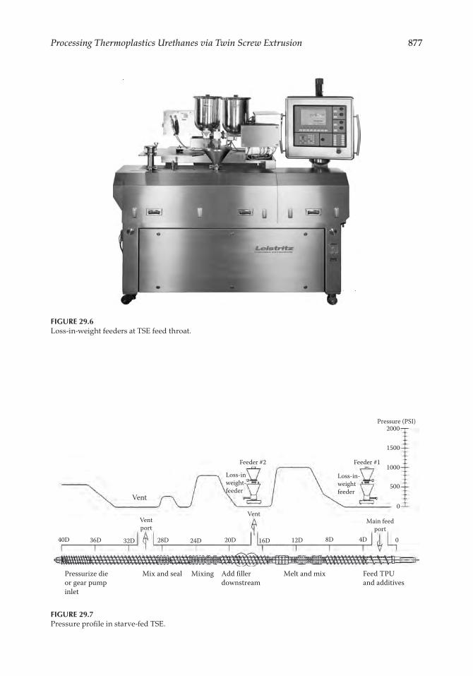
The pressure gradient in the twin screw extruder is determined by the selection of screws. Flighted elements are strategically placed so that the screw channels are not entirely filled which results in a zero pressure underneath downstream vent/feed sec-tions, which facilitates downstream feeding of fillers and fibers, and also prevents vent flooding (Figure 29.7).
A “side stuffer” is a device that is commonly integrated with a TSE to introduce fillers, fibers, and other materials into the process melt stream after plastication. Like a TSE, a side stuffer utilizes corotating, intermeshing, self-wiping screws to “push” materials into an
Figure 29.5Graphical HMI touch screen example.
877Processing Thermoplastics Urethanes via Twin Screw Extrusion
Figure 29.6Loss-in-weight feeders at TSE feed throat.
Pressure (PSI)2000
Feeder #1
Main feedport
Ventport
Feeder #2
Vent
40D 36D 32D 28D
Mix and sealPressurize dieor gear pumpinlet
Add fillerdownstream
Feed TPUand additives
Mixing Melt and mix
24D 20D 16D 12D 8D 4D 0
Vent
Loss-in-weightfeeder
Loss-inweight-feeder
1500
1000
500
0
Figure 29.7Pressure profile in starve-fed TSE.
878 Szycher’s Handbook of Polyurethanes
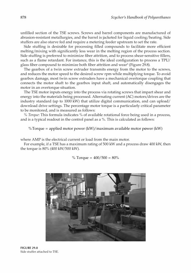
unfilled section of the TSE screws. Screws and barrel components are manufactured of abrasion-resistant metallurgies, and the barrel is jacketed for liquid cooling/heating. Side stuffers are also starve fed and require a metering feeder upstream to set the rate.
Side stuffing is desirable for processing filled compounds to facilitate more efficient melting/mixing with significantly less wear in the melting region of the process section. Side stuffing is preferred to minimize fiber attrition, and to process shear-sensitive fillers, such as a flame retardant. For instance, this is the ideal configuration to process a TPU/glass fiber compound to minimize both fiber attrition and wear3 (Figure 29.8).
The gearbox of a twin screw extruder transmits energy from the motor to the screws, and reduces the motor speed to the desired screw rpm while multiplying torque. To avoid gearbox damage, most twin screw extruders have a mechanical overtorque coupling that connects the motor shaft to the gearbox input shaft, and automatically disengages the motor in an overtorque situation.
The TSE motor inputs energy into the process via rotating screws that impart shear and energy into the materials being processed. Alternating current (AC) motors/drives are the industry standard (up to 1000 kW) that utilize digital communication, and can upload/download drive settings. The percentage motor torque is a particularly critical parameter to be monitored, and is measured as follows:
% Torque: This formula indicates % of available rotational force being used in a process, and is a typical readout in the control panel as a %. This is calculated as follows:
% ( )Torque applied motor power kW /maximum available motor p= oower kW( )
where AMP is the electrical current or load from the main motor.For example, if a TSE has a maximum rating of 500 kW and a process draw 400 kW, then
the torque is 80% (400 kW/500 kW).
% % Torque 4 /5 8= =00 00 0
Figure 29.8Side stuffer attached to TSE.
879Processing Thermoplastics Urethanes via Twin Screw Extrusion
For quality control and process troubleshooting, specific energy (SE) is a critical param-eter to be monitored, which can be determined as follows:
Specific energy: Specific energy is the amount of power that is being input by the motor into each kilogram of material being processed. This is calculated in two steps:
Applied power:
kW(applied) = kW(motor rating) × % torque × rpm running/maximum rpm × 0.97 (gearbox efficiency)
Now the SE can be calculated:
SE
kW appliedkg/h
= ( )
whereSE is denoted in kW per kg/hkW = kilowatts (the motor rating, kW = HP × 0.746)% Torque = % used of the maximum allowable torquerpm = screw rotations per minute
For example:A 40-mm twin screw extruder is processing a TPU/PP alloy at 100 kg/h, running at
200 rpm with 68% torque. The machine has a 56-kW (~75 HP) motor and a maximum screw rpm of 600.
kW applied 56 kW 68 2 /6 97 154 kW per kg/h( ) . . .= × × × =0 00 00 0 0
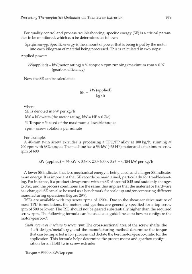
A lower SE indicates that less mechanical energy is being used, and a larger SE indicates more energy. It is important that SE records be maintained, particularly for troubleshoot-ing. For instance, if a product always runs with an SE of around 0.15 and suddenly changes to 0.26, and the process conditions are the same; this implies that the material or hardware has changed. SE can also be used as a benchmark for scale-up and/or comparing different manufacturing operations (Figure 29.9).
TSEs are available with top screw rpms of 1200+. Due to the shear-sensitive nature of most TPU formulations, the motors and gearbox are generally specified for a top screw rpm of 500 or lower. The TSE should not be geared substantially higher than the required screw rpm. The following formula can be used as a guideline as to how to configure the motor/gearbox3:
Shaft torque as it relates to screw rpm: The cross-sectional area of the screw shafts, the shaft design/metallurgy, and the manufacturing method determine the torque that can be imparted into a process and dictate the best motor/gearbox ratio for the application. This formula helps determine the proper motor and gearbox configu-ration for an HSEI twin screw extruder:
Torque = 9550 × kW/top rpm
880 Szycher’s Handbook of Polyurethanes
where9550 = constantTorque = total torque for both screw shafts, typically denoted in Nm (Newton meters)kW = motor rating on the HSEI twin screw extruder
For example:If an HSEI twin screw extruder with a 60-mm screw diameter has a torque rating of
3200 Nm and uses a 200-kW motor if geared for 600 rpm at full torque, then a 400-kW motor would be specified at 1200 rpm as indicated below:
32 955 2 32 955 400 0 00600
00 0 001200
= × = ×
If a machine will never operate above 600 rpm, it should not be geared for 1200. Since the torque is a constant, a 60-mm twin screw extruder can be geared either at 600 rpm with a 200-kW motor or at 1200 rpm with a 400-kW motor (or with another motor/gearbox com-bination). At 600 rpm and below, the performance will be exactly the same, since the applied torque and free volume are unchanged. Accordingly, high rpms should not be specified for TPU processes unless it is planned to process other thermoplastics that ben-efit from higher screw speeds.
Sometimes the choice is between an HSEI twin screw extruder with a larger screw diam-eter operating at lower rpm or a smaller machine at higher rpm. The cost differential for both should be compared before a final selection is made, particularly for larger machines. For TPUs, upsizing with a lower top screw rpm is probably preferred.5
29.3 TSE Process Section: The “Key” to Success
The heart of the TSE is its screws and barrels, referred to as the process section. In a coro-tating, intermeshing twin screw extruder, the screws are termed “self-wiping.” The surface velocity of the screws in the intermesh region are in opposing directions, which results in
Figure 29.9Motor and gearbox attached to TSE process section.
881Processing Thermoplastics Urethanes via Twin Screw Extrusion
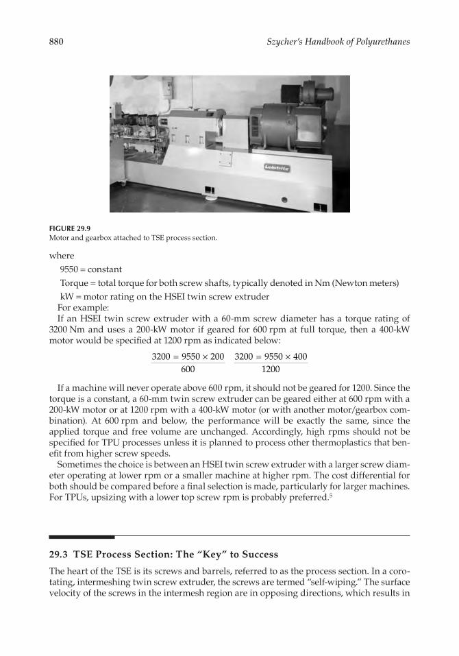
the materials being forced to follow the figure 8 pattern down the length of the screws (Figure 29.10).
There are an infinite number of screw design variations, and the screw design can be made shear intensive or passive. There are, however, only three basic types of screw ele-ments: flighted elements, mixing elements, and zoning elements. Flighted elements for-ward material past barrel ports, over mixers, and out of the extruder to the die. Zoning elements isolate two operations within the extruder, such as a melt seal prior to a vacuum vent. Through-hardened tool or stainless steels are generally specified for unfilled TPU products, while powdered metallurgies (PMs) are often specified when processing filled compounds.
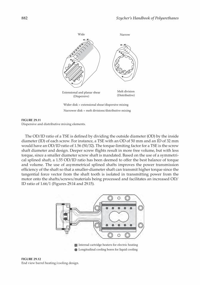
Mixing elements may be dispersive or distributive. The most common mixing element is a kneader. The wider a kneading element the more dispersive it becomes as extensional and planar shear effects are forced to occur as materials are forced up and over the land. Narrower kneading elements are more distributive in nature by facilitating high melt divi-sion rate mixing with little extensional and planar shear. Distributive mixing elements allow heat- and shear-sensitive materials to be mixed, such as glass fibers or flame retar-dants, without degradation/attrition. Kneading elements can be arranged with a forward pitch (less aggressive), neutral, or reverse pitch (most aggressive). High liquid phase mix-ing generally benefit from specialty distributive elements that prevent “pooling” of the liquids in the TSE process section6 (Figure 29.11).
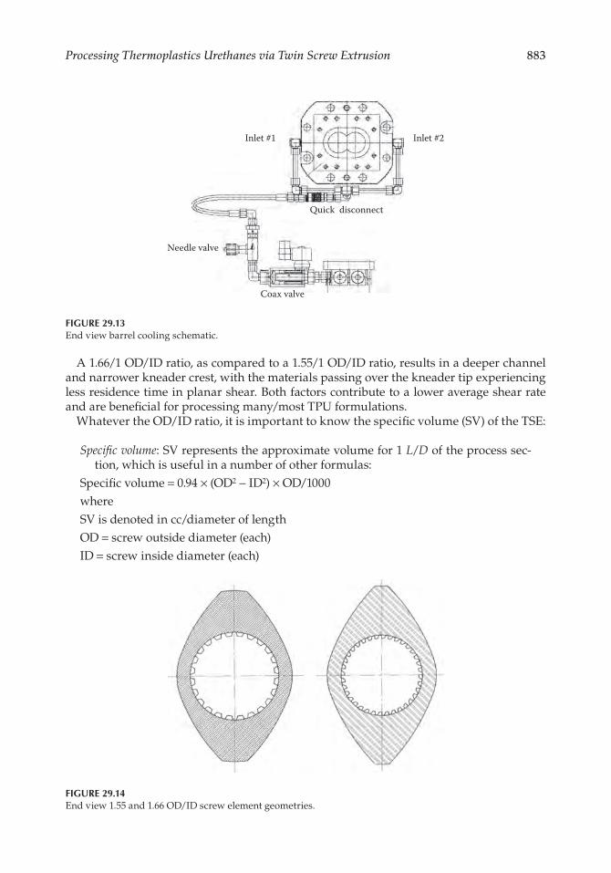
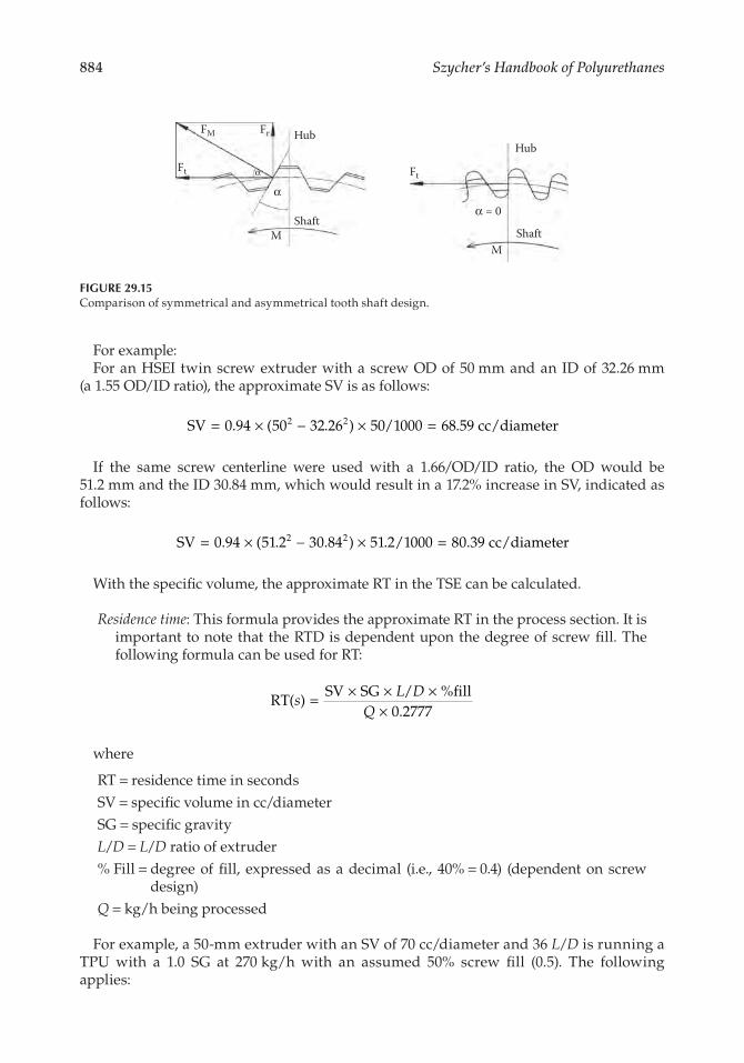
Modular TSE barrels typically use electric cartridge heaters and internal cooling bores for liquid cooling. State-of-the-art barrel designs utilize (1) inlet ports and (2) outlet ports for each barrel section to maximize coolant flow and cooling efficiencies. Increasing the coolant flow and heat transfer capabilities of the barrels is beneficial for heat-sensitive TPU formulations. Just like screws, through-hardened tool or stainless steels are adequate for most TPU processes, while PM liners are specified for highly filled formulations for increased wear resistance7 (Figures 29.12 and 29.13).
Typical unit operations performed in the TSE process section include feeding, melt-ing, conveyance, venting, and pumping. The length/diameter ratio (L/D) (the overall length of the process section divided by the screw diameter) of the TSE process section is matched to the number of unit operations that need to be performed. L/D ratios for TPU processes range from 28/1 for a premix feed to 60/1 L/D for some reactive processes.
+ +
Figure 29.10TSE self-wiping screws.
882 Szycher’s Handbook of Polyurethanes
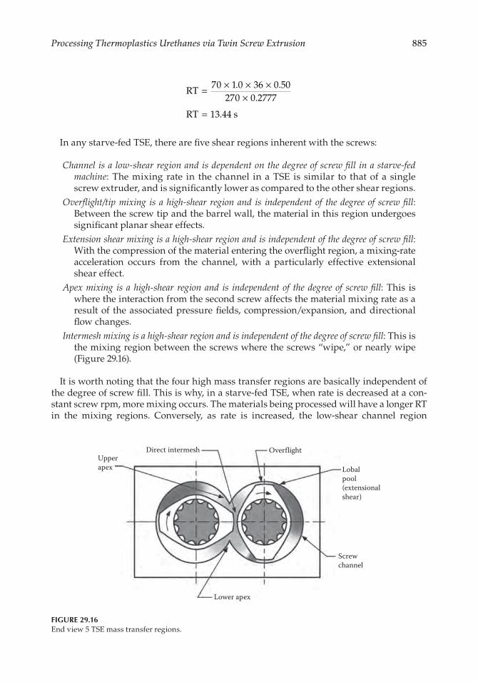
The OD/ID ratio of a TSE is defined by dividing the outside diameter (OD) by the inside diameter (ID) of each screw. For instance, a TSE with an OD of 50 mm and an ID of 32 mm would have an OD/ID ratio of 1.56 (50/32). The torque-limiting factor for a TSE is the screw shaft diameter and design. Deeper screw flights result in more free volume, but with less torque, since a smaller diameter screw shaft is mandated. Based on the use of a symmetri-cal splined shaft, a 1.55 OD/ID ratio has been deemed to offer the best balance of torque and volume. The use of asymmetrical splined shafts improves the power transmission efficiency of the shaft so that a smaller-diameter shaft can transmit higher torque since the tangential force vector from the shaft tooth is isolated in transmitting power from the motor onto the shafts/screws/materials being processed and facilitates an increased OD/ID ratio of 1.66/1 (Figures 29.14 and 29.15).
Wide
Extensional and planar shear(Dispersive)
Melt division(Distributive)
Wider disk = extensional shear/dispersive mixing
Narrower disk = melt divisions/distributive mixing
Narrow
Figure 29.11Dispersive and distributive mixing elements.
Internal cartridge heaters for electric heatingLongitudinal cooling bores for liquid cooling
Figure 29.12End view barrel heating/cooling design.
883Processing Thermoplastics Urethanes via Twin Screw Extrusion
A 1.66/1 OD/ID ratio, as compared to a 1.55/1 OD/ID ratio, results in a deeper channel and narrower kneader crest, with the materials passing over the kneader tip experiencing less residence time in planar shear. Both factors contribute to a lower average shear rate and are beneficial for processing many/most TPU formulations.
Whatever the OD/ID ratio, it is important to know the specific volume (SV) of the TSE:
Specific volume: SV represents the approximate volume for 1 L/D of the process sec-tion, which is useful in a number of other formulas:
Specific volume = 0.94 × (OD2 − ID2) × OD/1000whereSV is denoted in cc/diameter of lengthOD = screw outside diameter (each)ID = screw inside diameter (each)
Inlet #2
Quick disconnect
Inlet #1
Needle valve
Coax valve
Figure 29.13End view barrel cooling schematic.
Figure 29.14End view 1.55 and 1.66 OD/ID screw element geometries.
884 Szycher’s Handbook of Polyurethanes
For example:For an HSEI twin screw extruder with a screw OD of 50 mm and an ID of 32.26 mm
(a 1.55 OD/ID ratio), the approximate SV is as follows:
SV 94 5 32 26 5 /1 68 59 cc/diameter2= × − × =0 0 0 0002. ( . ) .
If the same screw centerline were used with a 1.66/OD/ID ratio, the OD would be 51.2 mm and the ID 30.84 mm, which would result in a 17.2% increase in SV, indicated as follows:
SV 94 51 2 3 84 51 2/1 8 39 cc/diameter2 2= × − × =0 0 000 0. ( . . ) . .
With the specific volume, the approximate RT in the TSE can be calculated.
Residence time: This formula provides the approximate RT in the process section. It is important to note that the RTD is dependent upon the degree of screw fill. The following formula can be used for RT:
RT
SV SG / fill2777
( )%
.s
L D= × × ××Q 0
where
RT = residence time in secondsSV = specific volume in cc/diameterSG = specific gravityL/D = L/D ratio of extruder% Fill = degree of fill, expressed as a decimal (i.e., 40% = 0.4) (dependent on screw
design)Q = kg/h being processed
For example, a 50-mm extruder with an SV of 70 cc/diameter and 36 L/D is running a TPU with a 1.0 SG at 270 kg/h with an assumed 50% screw fill (0.5). The following applies:
HubHub
ShaftM Shaft
M
FM
Ft
Fr
α = 0α
α Ft
Figure 29.15Comparison of symmetrical and asymmetrical tooth shaft design.
885Processing Thermoplastics Urethanes via Twin Screw Extrusion
RT7 1 36 5
27 2777
RT 13 44 s
= × × ××
=
0 0 0 00 0. .
.
.
In any starve-fed TSE, there are five shear regions inherent with the screws:
Channel is a low-shear region and is dependent on the degree of screw fill in a starve-fed machine: The mixing rate in the channel in a TSE is similar to that of a single screw extruder, and is significantly lower as compared to the other shear regions.
Overflight/tip mixing is a high-shear region and is independent of the degree of screw fill: Between the screw tip and the barrel wall, the material in this region undergoes significant planar shear effects.
Extension shear mixing is a high-shear region and is independent of the degree of screw fill: With the compression of the material entering the overflight region, a mixing-rate acceleration occurs from the channel, with a particularly effective extensional shear effect.
Apex mixing is a high-shear region and is independent of the degree of screw fill: This is where the interaction from the second screw affects the material mixing rate as a result of the associated pressure fields, compression/expansion, and directional flow changes.
Intermesh mixing is a high-shear region and is independent of the degree of screw fill: This is the mixing region between the screws where the screws “wipe,” or nearly wipe (Figure 29.16).
It is worth noting that the four high mass transfer regions are basically independent of the degree of screw fill. This is why, in a starve-fed TSE, when rate is decreased at a con-stant screw rpm, more mixing occurs. The materials being processed will have a longer RT in the mixing regions. Conversely, as rate is increased, the low-shear channel region
Direct intermesh Overflight
Lobalpool(extensionalshear)
Screwchannel
Lower apex
Upperapex
Figure 29.16End view 5 TSE mass transfer regions.
886 Szycher’s Handbook of Polyurethanes
dominates more, and the materials being processed will spend less time in the mixing zones, and less mixing occurs.
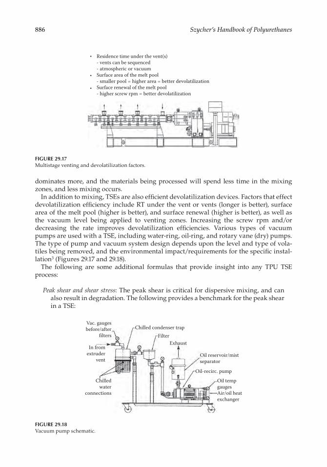
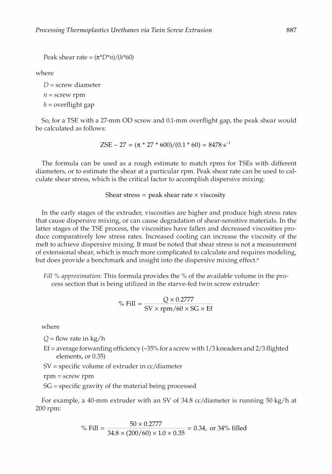
In addition to mixing, TSEs are also efficient devolatilization devices. Factors that effect devolatilization efficiency include RT under the vent or vents (longer is better), surface area of the melt pool (higher is better), and surface renewal (higher is better), as well as the vacuum level being applied to venting zones. Increasing the screw rpm and/or decreasing the rate improves devolatilization efficiencies. Various types of vacuum pumps are used with a TSE, including water-ring, oil-ring, and rotary vane (dry) pumps. The type of pump and vacuum system design depends upon the level and type of vola-tiles being removed, and the environmental impact/requirements for the specific instal-lation3 (Figures 29.17 and 29.18).
The following are some additional formulas that provide insight into any TPU TSE process:
Peak shear and shear stress: The peak shear is critical for dispersive mixing, and can also result in degradation. The following provides a benchmark for the peak shear in a TSE:
Residence time under the vent(s)- vents can be sequenced- atmospheric or vacuum Surface area of the melt pool- smaller pool = higher area = better devolatilizationSurface renewal of the melt pool- higher screw rpm = better devolatilization
Figure 29.17Multistage venting and devolatilization factors.
Vac. gaugesbefore/after
filtersChilled condenser trap
FilterExhaust
Oil reservoir/mistseparator
Oil-recirc. pump
Oil tempgaugesAir/oil heatexchanger
In fromextruder
vent
Chilledwater
connections
Figure 29.18Vacuum pump schematic.
887Processing Thermoplastics Urethanes via Twin Screw Extrusion
Peak shear rate = (π*D*n)/(h*60)
where
D = screw diametern = screw rpmh = overflight gap
So, for a TSE with a 27-mm OD screw and 0.1-mm overflight gap, the peak shear would be calculated as follows:
ZSE 27 27 6 / 1 6 8478 s 1− = = −( * * ) ( . * )π 00 0 0
The formula can be used as a rough estimate to match rpms for TSEs with different diameters, or to estimate the shear at a particular rpm. Peak shear rate can be used to cal-culate shear stress, which is the critical factor to accomplish dispersive mixing:
Shear stress peak shear rate viscosity= ×
In the early stages of the extruder, viscosities are higher and produce high stress rates that cause dispersive mixing, or can cause degradation of shear-sensitive materials. In the latter stages of the TSE process, the viscosities have fallen and decreased viscosities pro-duce comparatively low stress rates. Increased cooling can increase the viscosity of the melt to achieve dispersive mixing. It must be noted that shear stress is not a measurement of extensional shear, which is much more complicated to calculate and requires modeling, but does provide a benchmark and insight into the dispersive mixing effect.6
Fill % approximation: This formula provides the % of the available volume in the pro-cess section that is being utilized in the starve-fed twin screw extruder:
%
. Fill
2777SV rpm/ SG Ef
= ×× × ×
Q 060
where
Q = flow rate in kg/hEf = average forwarding efficiency (~35% for a screw with 1/3 kneaders and 2/3 flighted
elements, or 0.35)SV = specific volume of extruder in cc/diameterrpm = screw rpmSG = specific gravity of the material being processed
For example, a 40-mm extruder with an SV of 34.8 cc/diameter is running 50 kg/h at 200 rpm:
%
.. ( ) . .
. , % Fill5 2777
34 8 2 /6 1 3534 or 34 filled= ×
× × ×=0 0
00 0 0 00
888 Szycher’s Handbook of Polyurethanes
This calculation might show that devolatilization-intensive processes run at 40% screw fill because a starved process section increases the surface area of the melt pools under the vent or vents. Another example might demonstrate that similar masterbatch formulations for film applications utilize a 40% fill volume, compared to 60% for injection molding applications, because of the comparative dispersive mixing requirements.
This formula is a rough estimation and is meant primarily to provide some insight into the dynamics of a starve-fed TSE process section, as compared to an absolute value. More advanced/accurate calculations are available that take into account the specific screw geometries, the viscosity of the melt, and the degree of screw fill.
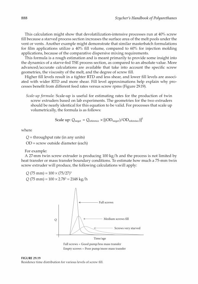
Higher fill levels result in a tighter RTD and less shear, and lower fill levels are associ-ated with wider RTD and more shear. Fill level approximations help explain why pro-cesses benefit from different feed rates versus screw rpms (Figure 29.19).
Scale-up formula: Scale-up is useful for estimating rates for the production of twin screw extruders based on lab experiments. The geometries for the two extruders should be nearly identical for this equation to be valid. For processes that scale up volumetrically, the formula is as follows:
Scale up: OD /ODtarget reference target reference3Q Q= × [( ) )]
where
Q = throughput rate (in any units)OD = screw outside diameter (each)
For example:A 27-mm twin screw extruder is producing 100 kg/h and the process is not limited by
heat transfer or mass transfer boundary conditions. To estimate how much a 75-mm twin screw extruder will produce, the following calculations will apply:
Q (75 mm) = 100 × (75/27)3
Q (75 mm) = 100 × 2.783 = 2148 kg/h
Full screws
Medium screws fill
Screws very starved
Time/age
Q
Full screws = Good pump/less mass transferEmpty screws = Poor pump/more mass transfer
Figure 29.19Residence time distribution for various levels of screw fill.
889Processing Thermoplastics Urethanes via Twin Screw Extrusion
The greater the difference in extruder sizes, the less reliable this calculation becomes. For a heat transfer-limited process, the exponent is closer to 2. For devolatilization and many TPU processes, the scale-up exponent is between 2.3 and 2.5. Advanced formulas and computer modeling approaches are also available for more intensive scale-up work.5
How the TSE is configured and operated makes the difference between success and fail-ure. In addition to the process section design (screws/barrels), feeds rate, screw rpm, tem-peratures, and sequence/location of feed streams all play a role in the shear intensity to which the materials are exposed. The following table provides a brief overview of how a TPU process can be managed:
Conditions Regulating Process Intensity
Type of Processing Gentle Strong
Screws’ speed Low HighMixing rate in each of the five mass transfer regions along the screws is proportional to screw rpm
Screws’ fill High LowStarving the feed increases remastication and time in mixers to increase process intensity
Temperature High LowLowering the temperature increases the controlling modulus in dispersive stress rate = Ec × strain rate
Extensional/planar shear events Low HighIncreasing the number, intensity of mixing events increases process severity
Sequential feed Depends DependsSequential feed may be employed to either capture or avoid high stress rate exposure
The balance between the rate set by feeders and the screw rpm is critical, as well as the temperature and screw design.
29.4 Downstream Systems
Pelletization is a downstream operation that transforms the molten TPU into a pellet to facilitate consistent feeding into an injection molding machine or single screw extruder. Various types of pelletizing systems are available, with the type selected based upon the material characteristics, throughput rate, and lot size. Pellet size ranges from 1/2 to 4 mm.
Strand pelletizing systems cut strands into cylinders and are widely used to produce TPU pellets. The TSE pumps the melt through a “spaghetti” strand die and the strands are then pulled through a water bath by feedrolls and cut by a bed knife/rotor assem-bly. Water baths utilize guide rollers to facilitate strand management prior to the pellet-izer, with TPUs often utilizing multipass stranding through the water bath for space conservation. Upon exit from the water bath, an air stripper removes surface moisture using either an air blower or vacuum. TPU strands are “drawn down” in diameter after
890 Szycher’s Handbook of Polyurethanes
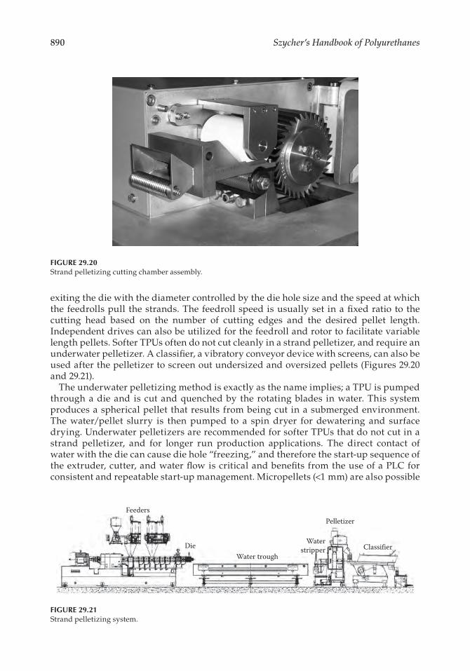
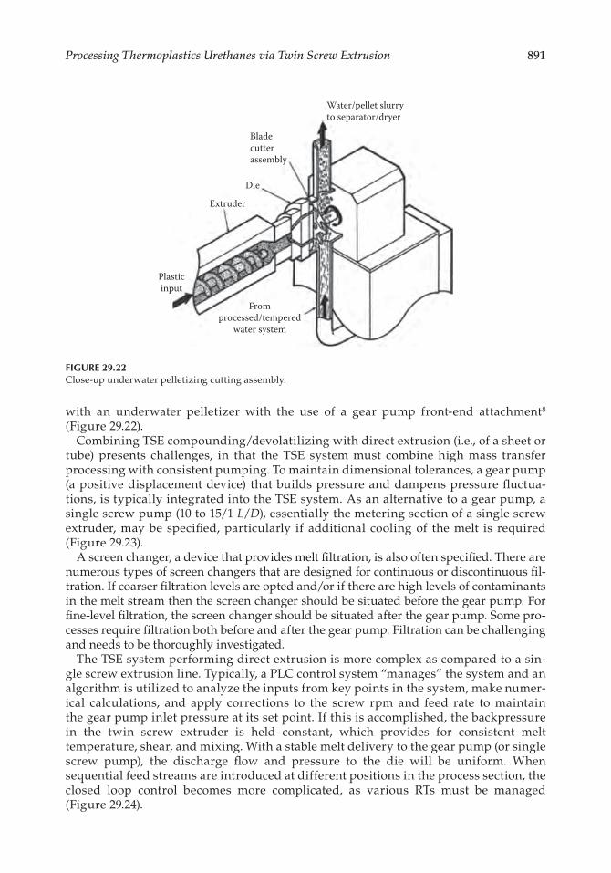
exiting the die with the diameter controlled by the die hole size and the speed at which the feedrolls pull the strands. The feedroll speed is usually set in a fixed ratio to the cutting head based on the number of cutting edges and the desired pellet length. Independent drives can also be utilized for the feedroll and rotor to facilitate variable length pellets. Softer TPUs often do not cut cleanly in a strand pelletizer, and require an underwater pelletizer. A classifier, a vibratory conveyor device with screens, can also be used after the pelletizer to screen out undersized and oversized pellets (Figures 29.20 and 29.21).
The underwater pelletizing method is exactly as the name implies; a TPU is pumped through a die and is cut and quenched by the rotating blades in water. This system produces a spherical pellet that results from being cut in a submerged environment. The water/pellet slurry is then pumped to a spin dryer for dewatering and surface drying. Underwater pelletizers are recommended for softer TPUs that do not cut in a strand pelletizer, and for longer run production applications. The direct contact of water with the die can cause die hole “freezing,” and therefore the start-up sequence of the extruder, cutter, and water flow is critical and benefits from the use of a PLC for consistent and repeatable start-up management. Micropellets (<1 mm) are also possible
Feeders
DieWater trough
Waterstripper
Pelletizer
Classifier
Figure 29.21Strand pelletizing system.
Figure 29.20Strand pelletizing cutting chamber assembly.
891Processing Thermoplastics Urethanes via Twin Screw Extrusion
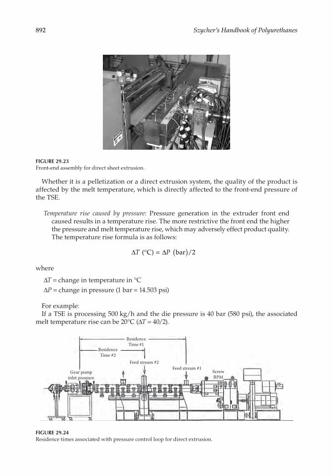
with an underwater pelletizer with the use of a gear pump front-end attachment8 (Figure 29.22).
Combining TSE compounding/devolatilizing with direct extrusion (i.e., of a sheet or tube) presents challenges, in that the TSE system must combine high mass transfer processing with consistent pumping. To maintain dimensional tolerances, a gear pump (a positive displacement device) that builds pressure and dampens pressure fluctua-tions, is typically integrated into the TSE system. As an alternative to a gear pump, a single screw pump (10 to 15/1 L/D), essentially the metering section of a single screw extruder, may be specified, particularly if additional cooling of the melt is required (Figure 29.23).
A screen changer, a device that provides melt filtration, is also often specified. There are numerous types of screen changers that are designed for continuous or discontinuous fil-tration. If coarser filtration levels are opted and/or if there are high levels of contaminants in the melt stream then the screen changer should be situated before the gear pump. For fine-level filtration, the screen changer should be situated after the gear pump. Some pro-cesses require filtration both before and after the gear pump. Filtration can be challenging and needs to be thoroughly investigated.
The TSE system performing direct extrusion is more complex as compared to a sin-gle screw extrusion line. Typically, a PLC control system “manages” the system and an algorithm is utilized to analyze the inputs from key points in the system, make numer-ical calculations, and apply corrections to the screw rpm and feed rate to maintain the gear pump inlet pressure at its set point. If this is accomplished, the backpressure in the twin screw extruder is held constant, which provides for consistent melt temperature, shear, and mixing. With a stable melt delivery to the gear pump (or single screw pump), the discharge flow and pressure to the die will be uniform. When sequential feed streams are introduced at different positions in the process section, the closed loop control becomes more complicated, as various RTs must be managed (Figure 29.24).
Bladecutterassembly
Water/pellet slurryto separator/dryer
Die
Extruder
Plasticinput
Fromprocessed/tempered
water system
Figure 29.22Close-up underwater pelletizing cutting assembly.
892 Szycher’s Handbook of Polyurethanes
Whether it is a pelletization or a direct extrusion system, the quality of the product is affected by the melt temperature, which is directly affected to the front-end pressure of the TSE.
Temperature rise caused by pressure: Pressure generation in the extruder front end caused results in a temperature rise. The more restrictive the front end the higher the pressure and melt temperature rise, which may adversely effect product quality. The temperature rise formula is as follows:
∆ ∆T P C bar /2( )° = ( )
where
ΔT = change in temperature in °CΔP = change in pressure (1 bar = 14.503 psi)
For example:If a TSE is processing 500 kg/h and the die pressure is 40 bar (580 psi), the associated
melt temperature rise can be 20°C (ΔT = 40/2).
Figure 29.23Front-end assembly for direct sheet extrusion.
ResidenceTime #1
ResidenceTime #2
Gear pumpinlet pressure
Feed stream #2Feed stream #1
ScrewRPM
Figure 29.24Residence times associated with pressure control loop for direct extrusion.
893Processing Thermoplastics Urethanes via Twin Screw Extrusion
This formula is meant to be insightful, if not necessarily accurate, as TSE rpm and the geometry of the discharge screw elements play significant roles in the actual melt temperature.9
29.5 Examples of TPU Processes Performed on Twin Screw Extrusion Systems
The following summarizes a few examples of related processes/applications:
TPU reactive extrusion system with underwater pelletization: Polyurethanes can range from being hard like a thermoplastic to being flexible like an elastomer, with the properties determined by the balance between the isocyanates, polyols, chain extenders, and catalysts in the formulation. These liquids are often premixed in a reaction vessel prior to the TSE to increase the RT for the reaction. Reaction cylin-ders and high-speed mixers for monomer mixtures and prepolymers are com-monly integrated into the design.10
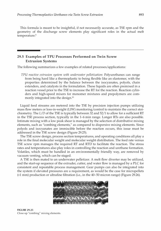
Liquid feed streams are metered into the TSE by precision injection pumps utilizing mass flow meters or loss-in-weight (LIW) monitoring/control to maintain the correct stoi-chiometry. The L/D of the TSE is typically between 32 and 52/1 to allow for a sufficient RT in the TSE process section, typically in the 1–6 min range. Longer RTs are also possible. Intimate mixing with a low peak shear is managed by the selection of distributive mixing elements, such as “combing elements,” as compared to dispersive mixing elements. Since polyols and isocyanates are immiscible before the reaction occurs, this issue must be addressed in the TSE screw design (Figure 29.25).
The TSE screw design, process section temperatures, and operating conditions all play a role in the final molecular weight and molecular weight distribution. The feed rate versus TSE screw rpm manages the required RT and RTD to facilitate the reaction. The stress rates and temperatures also play roles in controlling the reaction and urethane formation. Volatiles, which must be handled in an environmentally friendly way, are removed by vacuum venting, which can be staged.
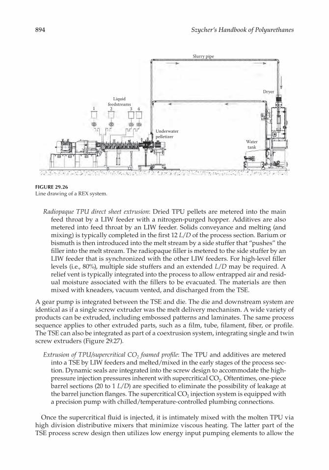
A TSE is then mated to an underwater pelletizer. A melt flow diverter may be utilized, and the start-up sequence of the extruder, cutter, and water flow is managed by a PLC for consistent and repeatable process management. Gear pumps can also be integrated into the system if elevated pressures are a requirement, as would be the case for micropellets (<1 mm) production or ultrafine filtration (i.e., in the 40–50 micron range) (Figure 29.26).
Figure 29.25Close-up “combing” mixing elements.
894 Szycher’s Handbook of Polyurethanes
Radiopaque TPU direct sheet extrusion: Dried TPU pellets are metered into the main feed throat by a LIW feeder with a nitrogen-purged hopper. Additives are also metered into feed throat by an LIW feeder. Solids conveyance and melting (and mixing) is typically completed in the first 12 L/D of the process section. Barium or bismuth is then introduced into the melt stream by a side stuffer that “pushes” the filler into the melt stream. The radiopaque filler is metered to the side stuffer by an LIW feeder that is synchronized with the other LIW feeders. For high-level filler levels (i.e., 80%), multiple side stuffers and an extended L/D may be required. A relief vent is typically integrated into the process to allow entrapped air and resid-ual moisture associated with the fillers to be evacuated. The materials are then mixed with kneaders, vacuum vented, and discharged from the TSE.
A gear pump is integrated between the TSE and die. The die and downstream system are identical as if a single screw extruder was the melt delivery mechanism. A wide variety of products can be extruded, including embossed patterns and laminates. The same process sequence applies to other extruded parts, such as a film, tube, filament, fiber, or profile. The TSE can also be integrated as part of a coextrusion system, integrating single and twin screw extruders (Figure 29.27).
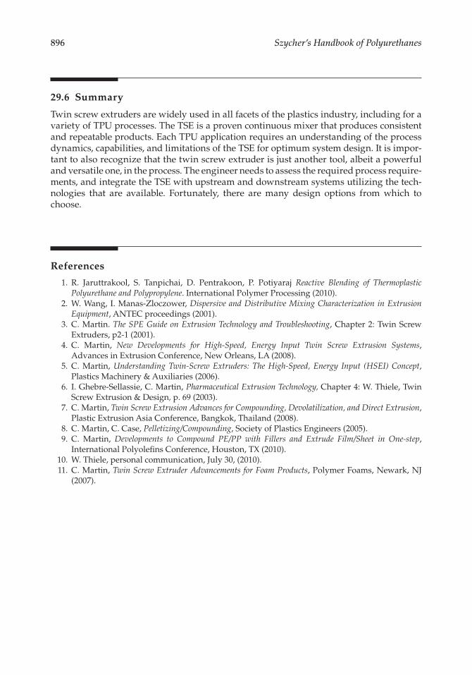
Extrusion of TPU/supercritical CO2 foamed profile: The TPU and additives are metered into a TSE by LIW feeders and melted/mixed in the early stages of the process sec-tion. Dynamic seals are integrated into the screw design to accommodate the high-pressure injection pressures inherent with supercritical CO2. Oftentimes, one-piece barrel sections (20 to 1 L/D) are specified to eliminate the possibility of leakage at the barrel junction flanges. The supercritical CO2 injection system is equipped with a precision pump with chilled/temperature-controlled plumbing connections.
Once the supercritical fluid is injected, it is intimately mixed with the molten TPU via high division distributive mixers that minimize viscous heating. The latter part of the TSE process screw design then utilizes low energy input pumping elements to allow the
Slurry pipe
DryerLiquid
feedstreams
Underwaterpelletizer
Watertank
1 2 3 4
Figure 29.26Line drawing of a REX system.
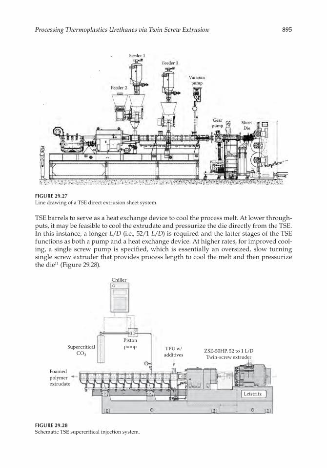
895Processing Thermoplastics Urethanes via Twin Screw Extrusion
TSE barrels to serve as a heat exchange device to cool the process melt. At lower through-puts, it may be feasible to cool the extrudate and pressurize the die directly from the TSE. In this instance, a longer L/D (i.e., 52/1 L/D) is required and the latter stages of the TSE functions as both a pump and a heat exchange device. At higher rates, for improved cool-ing, a single screw pump is specified, which is essentially an oversized, slow turning single screw extruder that provides process length to cool the melt and then pressurize the die11 (Figure 29.28).
Chiller
Pistonpump TPU w/
additivesZSE-50HP, 52 to 1 L/DTwin-screw extruder
Leistritz
SupercriticalCO2
Foamedpolymerextrudate
Figure 29.28Schematic TSE supercritical injection system.
Figure 29.27Line drawing of a TSE direct extrusion sheet system.
896 Szycher’s Handbook of Polyurethanes
29.6 Summary
Twin screw extruders are widely used in all facets of the plastics industry, including for a variety of TPU processes. The TSE is a proven continuous mixer that produces consistent and repeatable products. Each TPU application requires an understanding of the process dynamics, capabilities, and limitations of the TSE for optimum system design. It is impor-tant to also recognize that the twin screw extruder is just another tool, albeit a powerful and versatile one, in the process. The engineer needs to assess the required process require-ments, and integrate the TSE with upstream and downstream systems utilizing the tech-nologies that are available. Fortunately, there are many design options from which to choose.
References
1. R. Jaruttrakool, S. Tanpichai, D. Pentrakoon, P. Potiyaraj Reactive Blending of Thermoplastic Polyurethane and Polypropylene. International Polymer Processing (2010).
2. W. Wang, I. Manas-Zloczower, Dispersive and Distributive Mixing Characterization in Extrusion Equipment, ANTEC proceedings (2001).
3. C. Martin. The SPE Guide on Extrusion Technology and Troubleshooting, Chapter 2: Twin Screw Extruders, p2-1 (2001).
4. C. Martin, New Developments for High-Speed, Energy Input Twin Screw Extrusion Systems, Advances in Extrusion Conference, New Orleans, LA (2008).
5. C. Martin, Understanding Twin-Screw Extruders: The High-Speed, Energy Input (HSEI) Concept, Plastics Machinery & Auxiliaries (2006).
6. I. Ghebre-Sellassie, C. Martin, Pharmaceutical Extrusion Technology, Chapter 4: W. Thiele, Twin Screw Extrusion & Design, p. 69 (2003).
7. C. Martin, Twin Screw Extrusion Advances for Compounding, Devolatilization, and Direct Extrusion, Plastic Extrusion Asia Conference, Bangkok, Thailand (2008).
8. C. Martin, C. Case, Pelletizing/Compounding, Society of Plastics Engineers (2005). 9. C. Martin, Developments to Compound PE/PP with Fillers and Extrude Film/Sheet in One-step,
International Polyolefins Conference, Houston, TX (2010). 10. W. Thiele, personal communication, July 30, (2010). 11. C. Martin, Twin Screw Extruder Advancements for Foam Products, Polymer Foams, Newark, NJ
(2007).