Embed Size (px)
Citation preview

New Products 2010
Base Station & Marine AntennasCXL 70-5SL/...
CXL 2-5SL/...
CXL 470-870
PCPI xHCP-DP/TETRA
PCPI DCS
PCPI PCS
PCPI DECT
PCPI UMTS
PCPI WIFI
CXL 5700-6
CXL 5200-6LW
YA 2100
Mobile AntennasFF 4/2/TETRA/FM/GPS-BBMU
GPS-C 4/2/TETRA-S BBMU/...
GPS-C 4/2/TETRA-FM-S BBMU/...
DFSA 4/TETRA-BZ BBMU1
DFSA 4/TETRA-BZ BBMU2
GPS-C TETRA-I
MU 800/900/1800/2100/2600-LX
MU 800/900/1800/2100/2600-MMS
MU 901/1801-LX-SP
Portable AntennasEFD 345
FiltersBPF 2/3-HX-150
DPF 70/6-XL...
DPBP 70/3333-TETRA-N
BPF 70/33-TETRA-N, BPF 70/33-TETRA-7/16
PRO-DIPX 1000/1550-... HP
DIPX 1000/1550-DC-H/DCK
CombinersPRO-PHY150-5
PRO-PHY450-3/380-400/SWR
PRO-PHY450-4/380-400/SWR
Combiner componentsPRO-DIR 112-200-10 dB
PRO-DIR 112-200-20 dB
RPD 145-470/800-1000-10-N
PRO-IS-130-S1, PRO-IS-130-D1
PRO-IS-380-S1, PRO-IS-380-D1
PRO-PDI-4-TETRA-FME-J
PRO-DIR 0.45-0.8G-10 dB
MulticouplersMRPS800-2G-FME
MRPS2-GPS-...
PRO-RPS-2-GPS-N
PRO-RPS-4-GPS-N
PRO-RPS-8-GPS-N
PROCOM A/S · Tel. + 45 48 27 84 84 · [email protected] · www.procom.dk
CXL 70-5SL/...Sturdy, 5 dBd, Omnidirectional Base Station Antenna for theTETRA Bands
DESCRIPTION
CXL 70-5SL/… is a 5 dBd, vertically polarized, omnidirectional basestation antenna for the TETRA bands.
The antenna has a bandwidth of 20 MHz.The antenna is provided with our type "SL" (Slim Line) mast mount,a multipurpose mounting tube made of non-corrosive aluminium. Theaccompanying clamp set and fittings are made of hot-galvanizedsteel.The antenna can be mounted on mast tubes of 33 to 70 mm in outerdiameter.
The antenna element is sealed in a high-quality, conicalglass fibre tube with low wind-load, ensuring undisturbedperformance in all climates.
To substantially reduce noise caused by atmospherical discharges, allmetal parts in the antenna are DC-grounded. Consequently, theantenna shows a DC-short across the coaxial cable.
CXL 70-5SL/… is a vibration-proof, slim-line, corrosion-resistant,modern style base station antenna.
ORDERING DESIGNATIONS
TYPE PRODUCT NO. FREQUENCY
CXL 70-5SL/l 100000326 380 - 400 MHz
CXL 70-5SL/h 100000327 410 - 430 MHz
SPECIFICATIONS
ELECTRICAL
MODEL CXL 70-5SL/...
ANTENNA TYPE High-gain collinear
FREQUENCY 380 - 400 MHz and 410 - 430 MHz
IMPEDANCE Nom. 50 Ω
RADIATION Omnidirectional
POLARIZATION Vertical
GAIN 7 dBi 5 dBd
HALF POWER BEAMWIDTH 15°
BANDWIDTH 20 MHz
SWR ≤ 1.6
MAX. POWER 250 W
ANTISTATICPROTECTION
All metal parts DC-grounded(Connector shows a DC-short)
MECHANICAL
TEMP. RANGE -30°C → +70°C
CONNECTOR N-female
WIND SURFACE 0.21 m²
WIND LOAD 274 N @ 160 km/h
COLOUR Marine white
MATERIALS Radome: Polyurethane-coated glass fibreProcom clamp set: Hot-galvanized steel
TOTAL HEIGHT Approx. 3.2 m
WEIGHT Approx. 6 kg
MOUNTING On 33 - 70 mm dia. mast tube
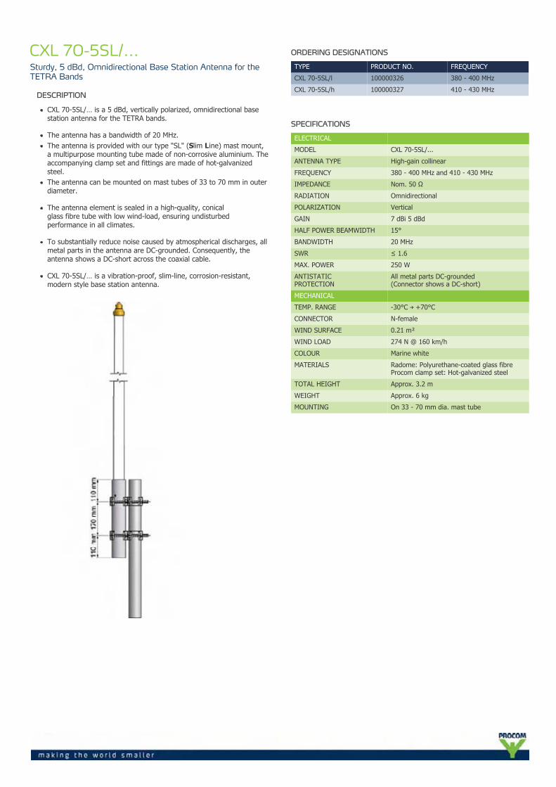
TYPICAL GAIN AND SWR CURVES
SWR¯ ¯ ¯
Gain dBd¯¯¯¯¯¯¯¯
f. MHz
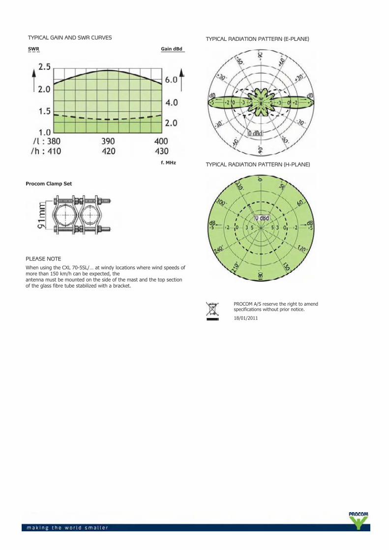
Procom Clamp Set
PLEASE NOTE
When using the CXL 70-5SL/… at windy locations where wind speeds ofmore than 150 km/h can be expected, theantenna must be mounted on the side of the mast and the top sectionof the glass fibre tube stabilized with a bracket.
TYPICAL RADIATION PATTERN (E-PLANE)
TYPICAL RADIATION PATTERN (H-PLANE)
PROCOM A/S reserve the right to amendspecifications without prior notice.
18/01/2011
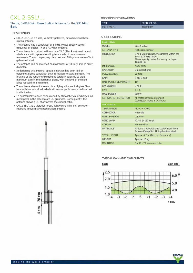
CXL 2-5SL/...Sturdy, 5 dBd Gain, Base Station Antenna for the 160 MHzBand
DESCRIPTION
CXL 2-5SL/… is a 5 dBd, vertically polarized, omnidirectional basestation antenna.The antenna has a bandwidth of 8 MHz. Please specify centrefrequency or duplex TX and RX when ordering.The antenna is provided with our type "SL" (Slim Line) mast mount,which is a multipurpose mounting tube made of non-corrosivealuminium. The accompanying clamp set and fittings are made of hotgalvanized steel.The antenna can be mounted on mast tubes of 33 to 70 mm in outerdiameter.In designing this antenna, special emphasis has been laid onobtaining a large bandwidth both in relation to SWR and gain. Thephasing of the radiating elements is carefully adjusted to yieldmaximum gain in the horizontal plane, with the level of the sidelobes reduced to a minimum.The antenna element is sealed in a high-quality, conical glass fibretube with low wind-load, which will ensure performance undisturbedin all climates.To substantially reduce noise caused by atmospherical discharges, allmetal parts in the antenna are DC-grounded. Consequently, theantenna shows a DC-short across the coaxial cable.CXL 2-5SL/… is a vibration-proof, lightweight, slim-line, corrosion-resistant, modern style base station antenna.
ORDERING DESIGNATIONS
TYPE PRODUCT NO.
CXL 2-5SL/... 100000325
SPECIFICATIONS
ELECTRICAL
MODEL CXL 2-5SL/...
ANTENNA TYPE High-gain colinear
FREQUENCY 8 MHz wide frequency segments within the144 - 175 MHz range.Please specify centre frequency or duplexTX and RX
IMPEDANCE Nom. 50 Ω
RADIATION Omnidirectional
POLARISATION Vertical
GAIN 7 dBi 5 dBd
HALF POWER BEAMWIDTH 18°
BANDWIDTH 8 MHz
SWR ≤ 1.6
MAX. POWER 500 W
ANTISTATIC PROTECTION All metal parts DC-grounded(connector shows a DC-short)
MECHANICAL
TEMP. RANGE -30°C → +70°C
CONNECTOR N-female
WIND SURFACE 0.374 m²
WIND LOAD 473 N @ 160 km/h
COLOUR Marine white
MATERIALS Radome : Polyurethane coated glass fibreProcom Clamp Set: Hot galvanized steel
TOTAL HEIGHT Approx. 6.2 m (Dep. on frequency)
WEIGHT Approx. 10 kg
MOUNTING On 33 - 70 mm mast tube
TYPICAL GAIN AND SWR CURVES
SWR¯ ¯ ¯
Gain dBd¯¯¯¯¯¯¯¯
f. MHz
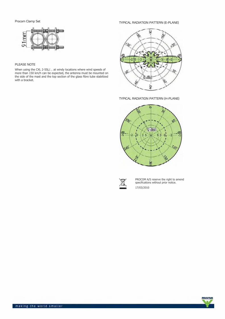
Procom Clamp Set
PLEASE NOTE
When using the CXL 2-5SL/… at windy locations where wind speeds ofmore than 150 km/h can be expected, the antenna must be mounted onthe side of the mast and the top section of the glass fibre tube stabilizedwith a bracket.
TYPICAL RADIATION PATTERN (E-PLANE)
TYPICAL RADIATION PATTERN (H-PLANE)
PROCOM A/S reserve the right to amendspecifications without prior notice.
17/03/2010
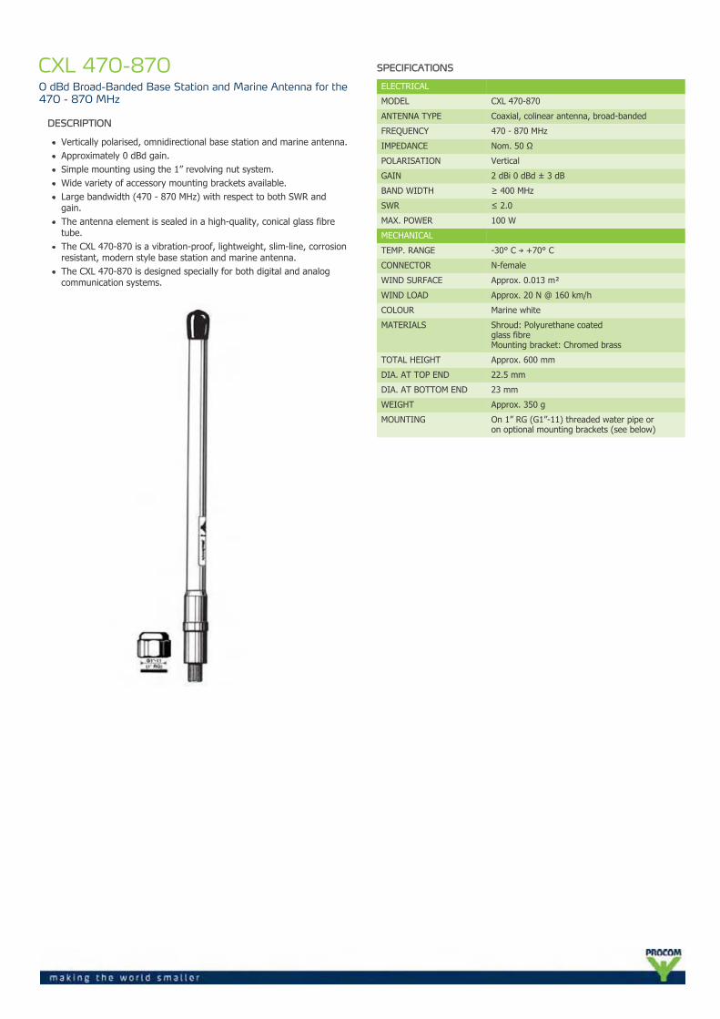
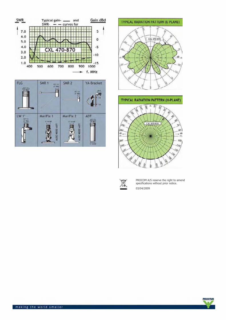
CXL 470-8700 dBd Broad-Banded Base Station and Marine Antenna for the470 - 870 MHz
DESCRIPTION
Vertically polarised, omnidirectional base station and marine antenna.Approximately 0 dBd gain.Simple mounting using the 1” revolving nut system.Wide variety of accessory mounting brackets available.Large bandwidth (470 - 870 MHz) with respect to both SWR andgain.The antenna element is sealed in a high-quality, conical glass fibretube.The CXL 470-870 is a vibration-proof, lightweight, slim-line, corrosionresistant, modern style base station and marine antenna.The CXL 470-870 is designed specially for both digital and analogcommunication systems.
SPECIFICATIONS
ELECTRICAL
MODEL CXL 470-870
ANTENNA TYPE Coaxial, colinear antenna, broad-banded
FREQUENCY 470 - 870 MHz
IMPEDANCE Nom. 50 Ω
POLARISATION Vertical
GAIN 2 dBi 0 dBd ± 3 dB
BAND WIDTH ≥ 400 MHz
SWR ≤ 2.0
MAX. POWER 100 W
MECHANICAL
TEMP. RANGE -30° C → +70° C
CONNECTOR N-female
WIND SURFACE Approx. 0.013 m²
WIND LOAD Approx. 20 N @ 160 km/h
COLOUR Marine white
MATERIALS Shroud: Polyurethane coatedglass fibreMounting bracket: Chromed brass
TOTAL HEIGHT Approx. 600 mm
DIA. AT TOP END 22.5 mm
DIA. AT BOTTOM END 23 mm
WEIGHT Approx. 350 g
MOUNTING On 1” RG (G1”-11) threaded water pipe oron optional mounting brackets (see below)
PROCOM A/S reserve the right to amendspecifications without prior notice.
03/04/2009
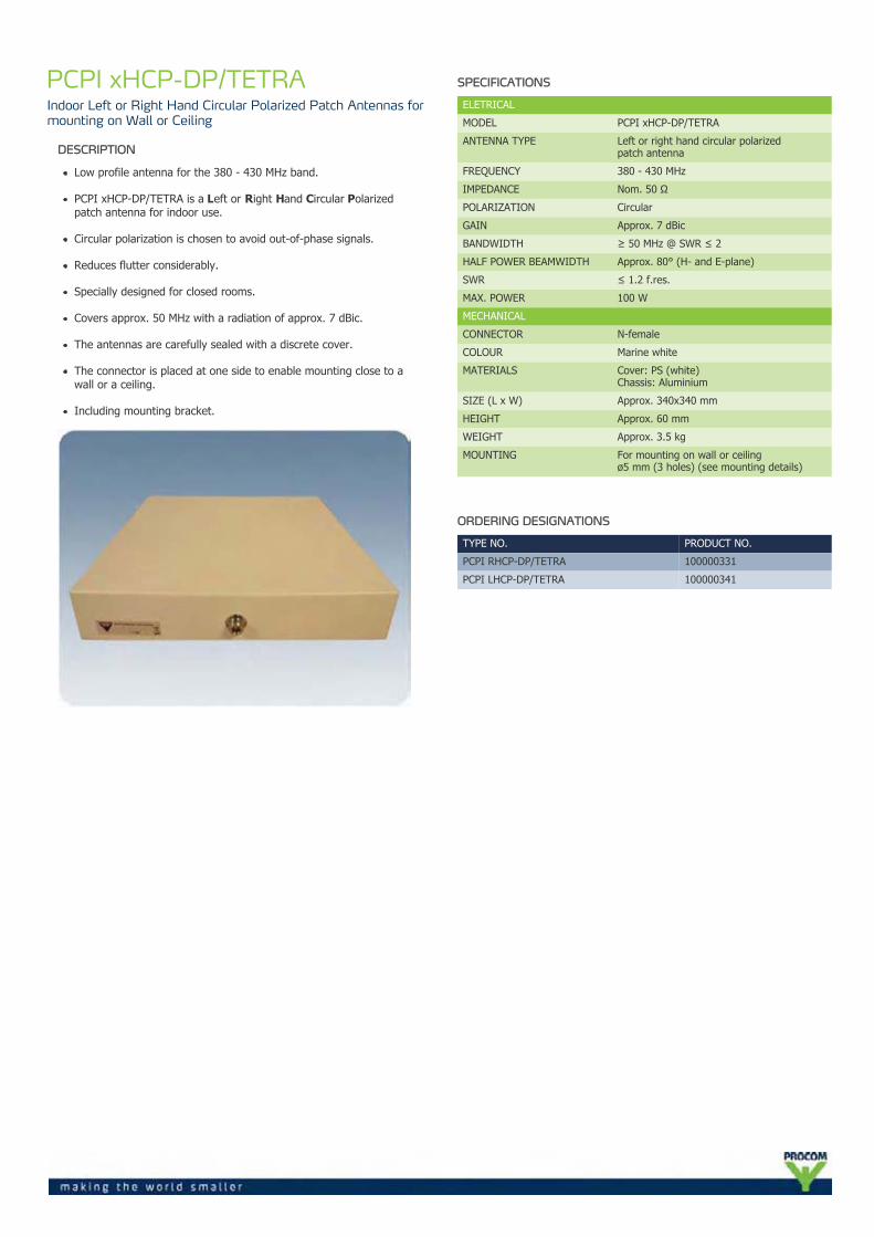
PCPI xHCP-DP/TETRAIndoor Left or Right Hand Circular Polarized Patch Antennas formounting on Wall or Ceiling
DESCRIPTION
Low profile antenna for the 380 - 430 MHz band.
PCPI xHCP-DP/TETRA is a Left or Right Hand Circular Polarizedpatch antenna for indoor use.
Circular polarization is chosen to avoid out-of-phase signals.
Reduces flutter considerably.
Specially designed for closed rooms.
Covers approx. 50 MHz with a radiation of approx. 7 dBic.
The antennas are carefully sealed with a discrete cover.
The connector is placed at one side to enable mounting close to awall or a ceiling.
Including mounting bracket.
SPECIFICATIONS
ELETRICAL
MODEL PCPI xHCP-DP/TETRA
ANTENNA TYPE Left or right hand circular polarizedpatch antenna
FREQUENCY 380 - 430 MHz
IMPEDANCE Nom. 50 Ω
POLARIZATION Circular
GAIN Approx. 7 dBic
BANDWIDTH ≥ 50 MHz @ SWR ≤ 2
HALF POWER BEAMWIDTH Approx. 80° (H- and E-plane)
SWR ≤ 1.2 f.res.
MAX. POWER 100 W
MECHANICAL
CONNECTOR N-female
COLOUR Marine white
MATERIALS Cover: PS (white)Chassis: Aluminium
SIZE (L x W) Approx. 340x340 mm
HEIGHT Approx. 60 mm
WEIGHT Approx. 3.5 kg
MOUNTING For mounting on wall or ceilingø5 mm (3 holes) (see mounting details)
ORDERING DESIGNATIONS
TYPE NO. PRODUCT NO.
PCPI RHCP-DP/TETRA 100000331
PCPI LHCP-DP/TETRA 100000341
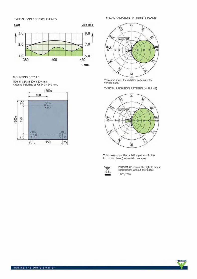
TYPICAL GAIN AND SWR CURVES
SWR¯ ¯ ¯
Gain dBic¯¯¯¯¯¯¯¯
f. MHz
MOUNTING DETAILS
Mounting plate 200 x 200 mm.Antenna including cover 340 x 340 mm.
TYPICAL RADIATION PATTERN (E-PLANE)
This curve shows the radiation patterns in thevertical plane.
TYPICAL RADIATION PATTERN (H-PLANE)
This curve shows the radiation patterns in thehorizontal plane (horizontal coverage).
PROCOM A/S reserve the right to amendspecifications without prior notice.
12/03/2010
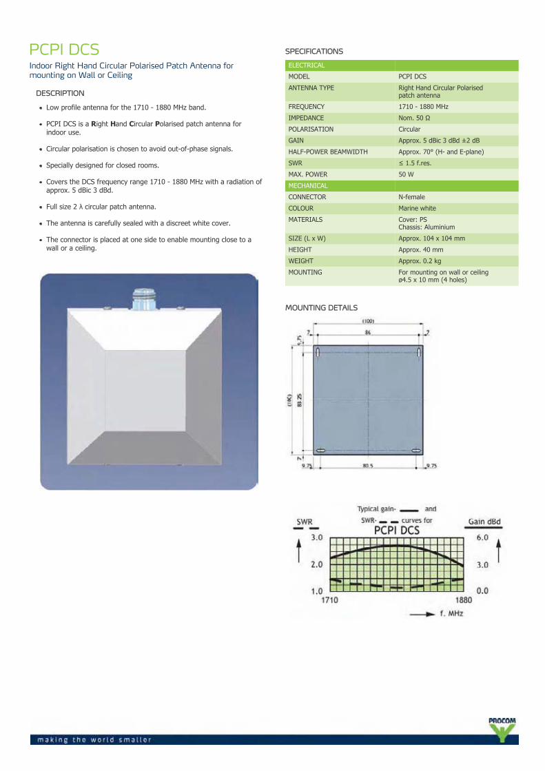
PCPI DCSIndoor Right Hand Circular Polarised Patch Antenna formounting on Wall or Ceiling
DESCRIPTION
Low profile antenna for the 1710 - 1880 MHz band.
PCPI DCS is a Right Hand Circular Polarised patch antenna forindoor use.
Circular polarisation is chosen to avoid out-of-phase signals.
Specially designed for closed rooms.
Covers the DCS frequency range 1710 - 1880 MHz with a radiation ofapprox. 5 dBic 3 dBd.
Full size 2 λ circular patch antenna.
The antenna is carefully sealed with a discreet white cover.
The connector is placed at one side to enable mounting close to awall or a ceiling.
SPECIFICATIONS
ELECTRICAL
MODEL PCPI DCS
ANTENNA TYPE Right Hand Circular Polarisedpatch antenna
FREQUENCY 1710 - 1880 MHz
IMPEDANCE Nom. 50 Ω
POLARISATION Circular
GAIN Approx. 5 dBic 3 dBd ±2 dB
HALF-POWER BEAMWIDTH Approx. 70° (H- and E-plane)
SWR ≤ 1.5 f.res.
MAX. POWER 50 W
MECHANICAL
CONNECTOR N-female
COLOUR Marine white
MATERIALS Cover: PSChassis: Aluminium
SIZE (L x W) Approx. 104 x 104 mm
HEIGHT Approx. 40 mm
WEIGHT Approx. 0.2 kg
MOUNTING For mounting on wall or ceilingø4.5 x 10 mm (4 holes)
MOUNTING DETAILS
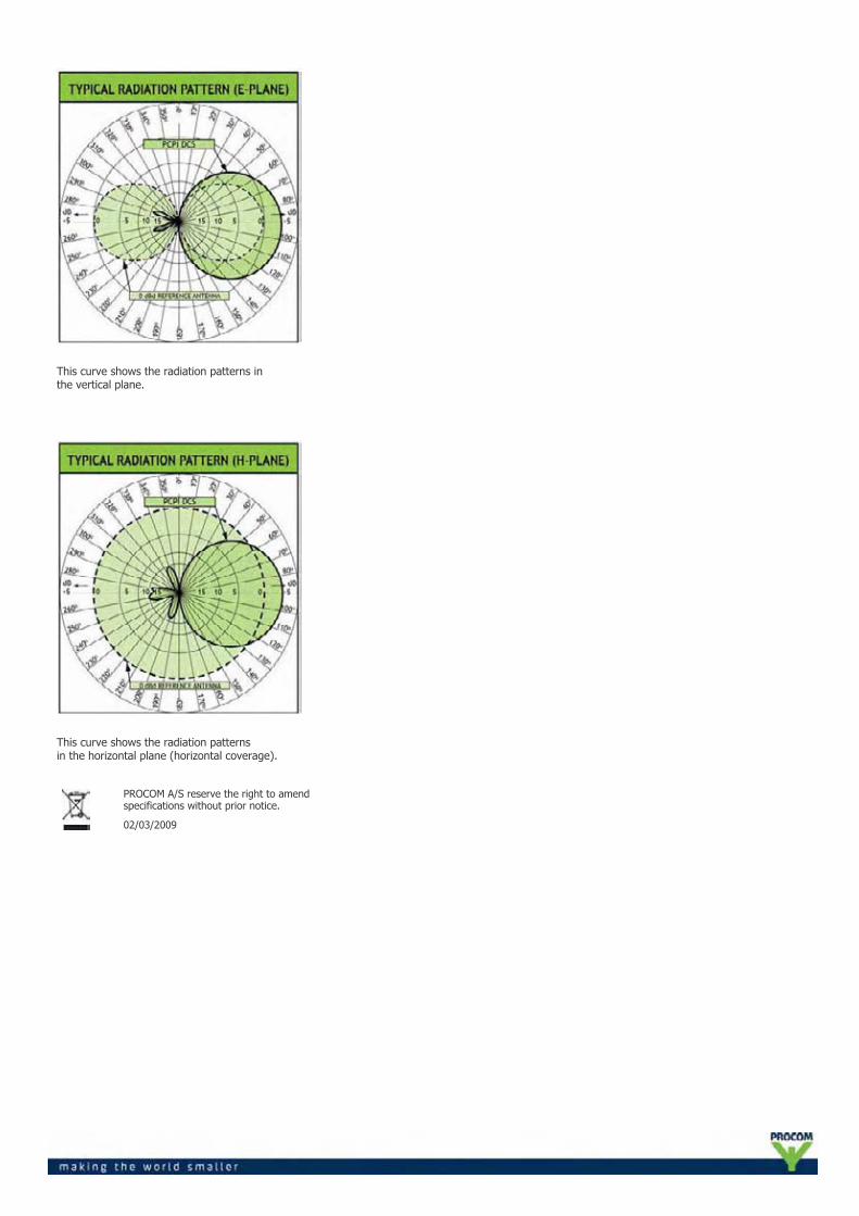
This curve shows the radiation patterns inthe vertical plane.
This curve shows the radiation patternsin the horizontal plane (horizontal coverage).
PROCOM A/S reserve the right to amendspecifications without prior notice.
02/03/2009

PCPI PCSIndoor Right Hand Circular Polarised Patch Antenna formounting on Wall or Ceiling
DESCRIPTION
Low profile antenna for the 1850 - 1990 MHz band.
PCPI PCS is a Right Hand Circular Polarised patch antenna for indooruse.
Circular polarisation is chosen to avoid out-of-phase signals.
Specially designed for closed rooms.
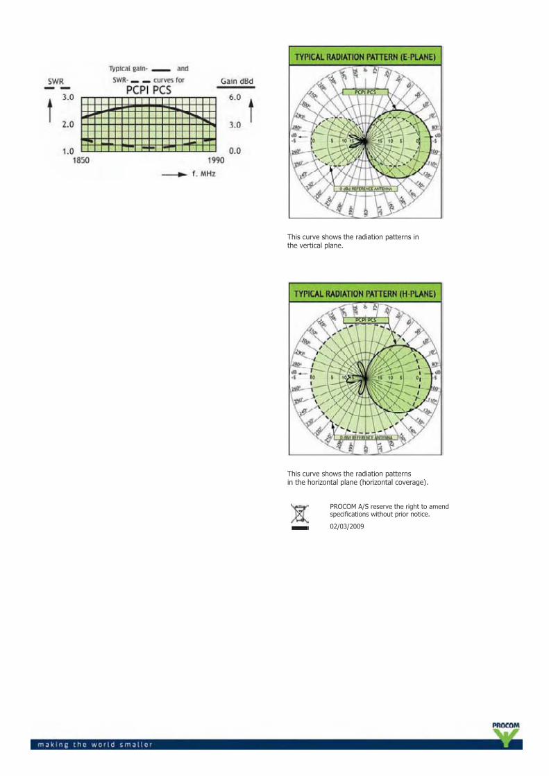
Covers the PCS frequency range 1850 - 1990 MHz with a radiation ofapprox. 5 dBic 3 dBd.
Full size 2 λ circular patch antenna.
The antenna is carefully sealed with a discreet white cover.
The connector is placed at one side to enable mounting close to awall or a ceiling.
SPECIFICATIONS
ELECTRICAL
MODEL PCPI PCS
ANTENNA TYPE Right Hand Circular Polarisedpatch antenna
FREQUENCY 1850 - 1990 MHz
IMPEDANCE Nom. 50 Ω
POLARISATION Circular
GAIN Approx. 5 dBic 3 dBd ±2 dB
HALF-POWER BEAMWIDTH Approx. 70° (H- and E-plane)
SWR ≤ 1.5 f.res.
MAX. POWER 50 W
MECHANICAL
CONNECTOR N-female
COLOUR Marine white
MATERIALS Cover: PSChassis: Aluminium
SIZE (L x W) Approx. 104 x 104 mm
HEIGHT Approx. 40 mm
WEIGHT Approx. 0.2 kg
MOUNTING For mounting on wall or ceilingø4.5 x 10 mm (4 holes)
MOUNTING DETAILS
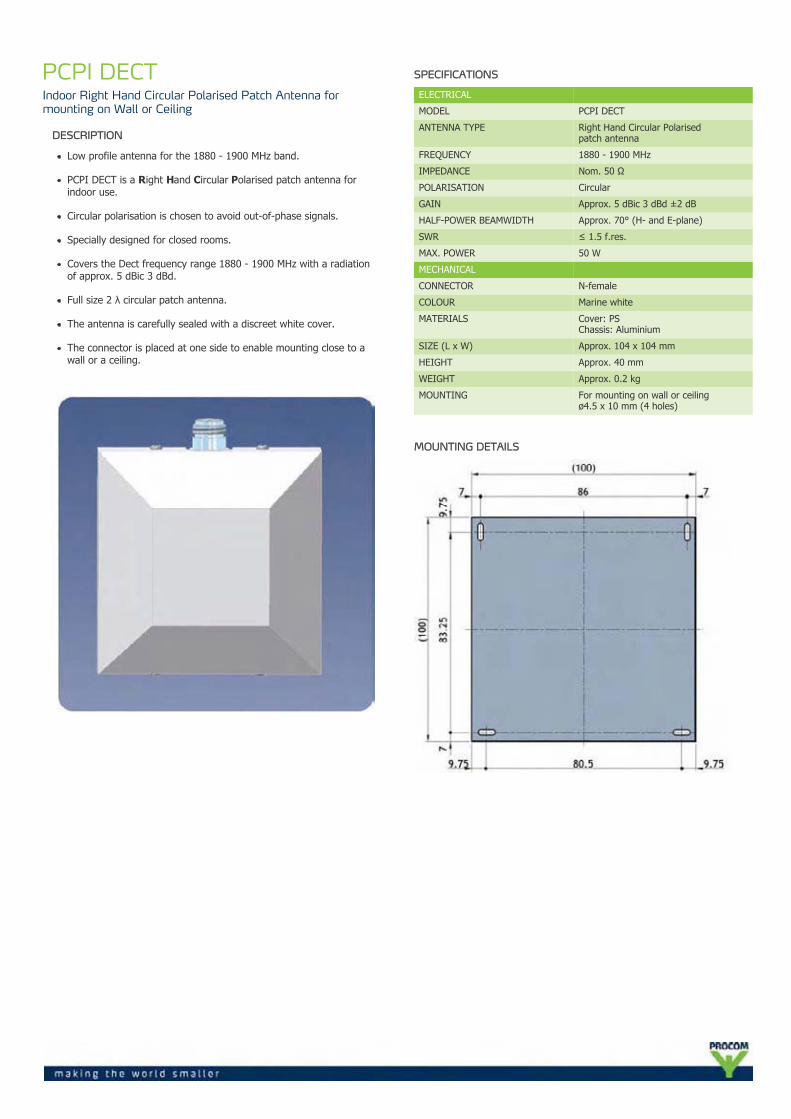
This curve shows the radiation patterns inthe vertical plane.
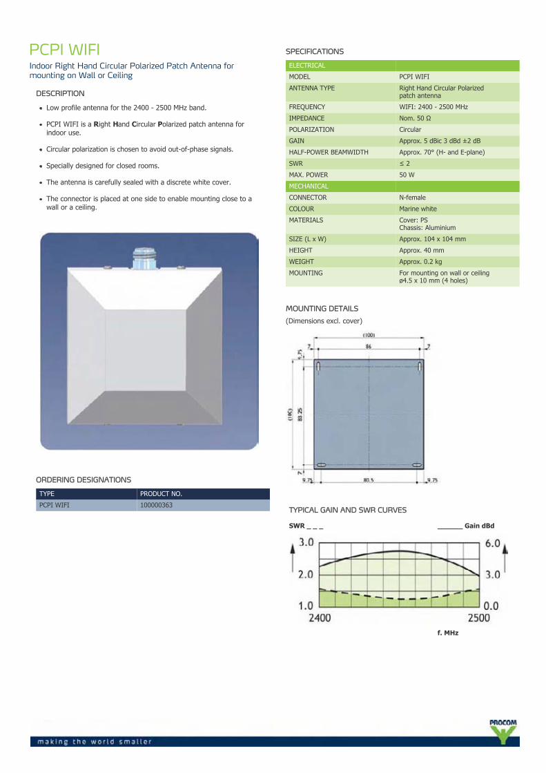
This curve shows the radiation patternsin the horizontal plane (horizontal coverage).
PROCOM A/S reserve the right to amendspecifications without prior notice.
02/03/2009
PCPI DECTIndoor Right Hand Circular Polarised Patch Antenna formounting on Wall or Ceiling
DESCRIPTION
Low profile antenna for the 1880 - 1900 MHz band.
PCPI DECT is a Right Hand Circular Polarised patch antenna forindoor use.
Circular polarisation is chosen to avoid out-of-phase signals.
Specially designed for closed rooms.
Covers the Dect frequency range 1880 - 1900 MHz with a radiationof approx. 5 dBic 3 dBd.
Full size 2 λ circular patch antenna.
The antenna is carefully sealed with a discreet white cover.
The connector is placed at one side to enable mounting close to awall or a ceiling.
SPECIFICATIONS
ELECTRICAL
MODEL PCPI DECT
ANTENNA TYPE Right Hand Circular Polarisedpatch antenna
FREQUENCY 1880 - 1900 MHz
IMPEDANCE Nom. 50 Ω
POLARISATION Circular
GAIN Approx. 5 dBic 3 dBd ±2 dB
HALF-POWER BEAMWIDTH Approx. 70° (H- and E-plane)
SWR ≤ 1.5 f.res.
MAX. POWER 50 W
MECHANICAL
CONNECTOR N-female
COLOUR Marine white
MATERIALS Cover: PSChassis: Aluminium
SIZE (L x W) Approx. 104 x 104 mm
HEIGHT Approx. 40 mm
WEIGHT Approx. 0.2 kg
MOUNTING For mounting on wall or ceilingø4.5 x 10 mm (4 holes)
MOUNTING DETAILS

This curve shows the radiation patterns inthe vertical plane.
This curve shows the radiation patternsin the horizontal plane (horizontal coverage).
PROCOM A/S reserve the right to amendspecifications without prior notice.
02/03/2009

PCPI UMTSIndoor Right Hand Circular Polarised Patch Antenna formounting on Wall or Ceiling
DESCRIPTION
Low profile antenna for the 1910 - 2200 MHz band.
PCPI UMTS is a Right Hand Circular Polarised patch antenna forindoor use.
Circular polarisation is chosen to avoid out-of-phase signals.
Specially designed for closed rooms.
Covers the UMTS frequency range 1910 - 2200 MHz with a radiationof approx. 5 dBic 3 dBd.
Full size 2 λ circular patch antenna.
The antenna is carefully sealed with a discreet white cover.
The connector is placed at one side to enable mounting close to awall or a ceiling.
SPECIFICATIONS
ELECTRICAL
MODEL PCPI UMTS
ANTENNA TYPE Right Hand Circular Polarisedpatch antenna
FREQUENCY 1910 - 2200 MHz
IMPEDANCE Nom. 50 Ω
POLARISATION Circular
GAIN Approx. 5 dBic 3 dBd ±2 dB
HALF-POWER BEAMWIDTH Approx. 70° (H- and E-plane)
SWR ≤ 1.5 f.res.
MAX. POWER 50 W
MECHANICAL
CONNECTOR N-female
COLOUR Marine white
MATERIALS Cover: PSChassis: Aluminium
SIZE (L x W) Approx. 104x104 mm
HEIGHT Approx. 40 mm
WEIGHT Approx. 0.2 kg
MOUNTING For mounting on wall or ceilingø4.5x10 mm (4 holes)
MOUNTING DETAILS

This curve shows the radiation patterns inthe vertical plane.
This curve shows the radiation patternsin the horizontal plane (horizontal coverage).
PROCOM A/S reserve the right to amendspecifications without prior notice.
02/03/2009
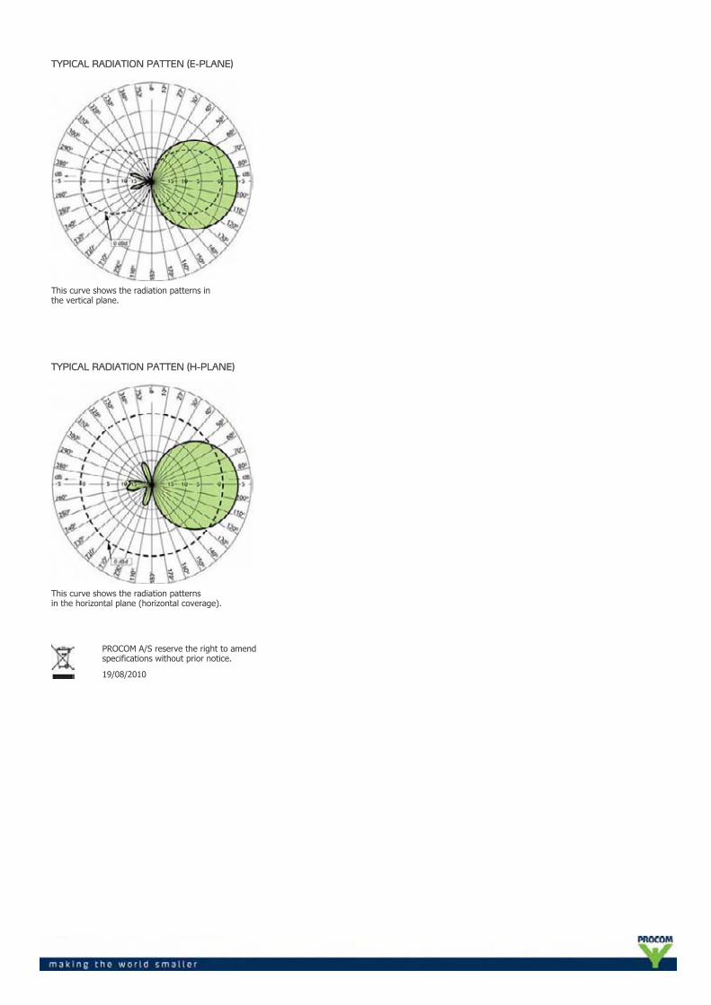
PCPI WIFIIndoor Right Hand Circular Polarized Patch Antenna formounting on Wall or Ceiling
DESCRIPTION
Low profile antenna for the 2400 - 2500 MHz band.
PCPI WIFI is a Right Hand Circular Polarized patch antenna forindoor use.
Circular polarization is chosen to avoid out-of-phase signals.
Specially designed for closed rooms.
The antenna is carefully sealed with a discrete white cover.
The connector is placed at one side to enable mounting close to awall or a ceiling.
ORDERING DESIGNATIONS
TYPE PRODUCT NO.
PCPI WIFI 100000363
SPECIFICATIONS
ELECTRICAL
MODEL PCPI WIFI
ANTENNA TYPE Right Hand Circular Polarizedpatch antenna
FREQUENCY WIFI: 2400 - 2500 MHz
IMPEDANCE Nom. 50 Ω
POLARIZATION Circular
GAIN Approx. 5 dBic 3 dBd ±2 dB
HALF-POWER BEAMWIDTH Approx. 70° (H- and E-plane)
SWR ≤ 2
MAX. POWER 50 W
MECHANICAL
CONNECTOR N-female
COLOUR Marine white
MATERIALS Cover: PSChassis: Aluminium
SIZE (L x W) Approx. 104 x 104 mm
HEIGHT Approx. 40 mm
WEIGHT Approx. 0.2 kg
MOUNTING For mounting on wall or ceilingø4.5 x 10 mm (4 holes)
MOUNTING DETAILS
(Dimensions excl. cover)
TYPICAL GAIN AND SWR CURVES
SWR _ _ _ ______ Gain dBd
f. MHz
TYPICAL RADIATION PATTEN (E-PLANE)
This curve shows the radiation patterns inthe vertical plane.
TYPICAL RADIATION PATTEN (H-PLANE)
This curve shows the radiation patternsin the horizontal plane (horizontal coverage).
PROCOM A/S reserve the right to amendspecifications without prior notice.
19/08/2010
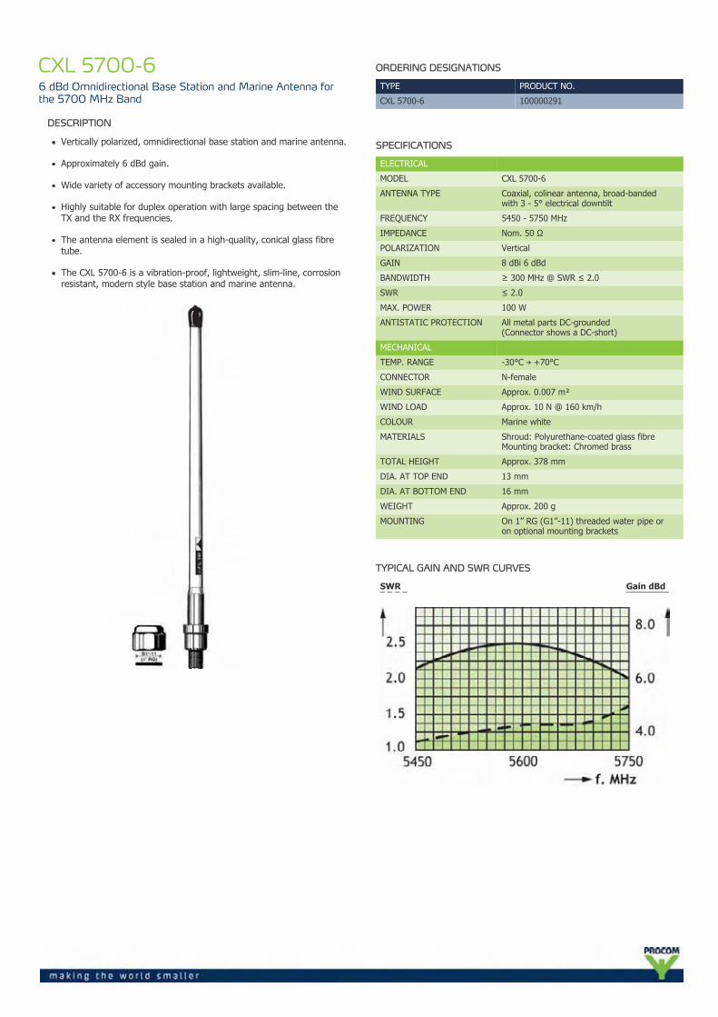
CXL 5700-66 dBd Omnidirectional Base Station and Marine Antenna forthe 5700 MHz Band
DESCRIPTION
Vertically polarized, omnidirectional base station and marine antenna.
Approximately 6 dBd gain.
Wide variety of accessory mounting brackets available.
Highly suitable for duplex operation with large spacing between theTX and the RX frequencies.
The antenna element is sealed in a high-quality, conical glass fibretube.
The CXL 5700-6 is a vibration-proof, lightweight, slim-line, corrosionresistant, modern style base station and marine antenna.
ORDERING DESIGNATIONS
TYPE PRODUCT NO.
CXL 5700-6 100000291
SPECIFICATIONS
ELECTRICAL
MODEL CXL 5700-6
ANTENNA TYPE Coaxial, colinear antenna, broad-bandedwith 3 - 5° electrical downtilt
FREQUENCY 5450 - 5750 MHz
IMPEDANCE Nom. 50 Ω
POLARIZATION Vertical
GAIN 8 dBi 6 dBd
BANDWIDTH ≥ 300 MHz @ SWR ≤ 2.0
SWR ≤ 2.0
MAX. POWER 100 W
ANTISTATIC PROTECTION All metal parts DC-grounded(Connector shows a DC-short)
MECHANICAL
TEMP. RANGE -30°C → +70°C
CONNECTOR N-female
WIND SURFACE Approx. 0.007 m²
WIND LOAD Approx. 10 N @ 160 km/h
COLOUR Marine white
MATERIALS Shroud: Polyurethane-coated glass fibreMounting bracket: Chromed brass
TOTAL HEIGHT Approx. 378 mm
DIA. AT TOP END 13 mm
DIA. AT BOTTOM END 16 mm
WEIGHT Approx. 200 g
MOUNTING On 1” RG (G1”-11) threaded water pipe oron optional mounting brackets
TYPICAL GAIN AND SWR CURVES
SWR¯ ¯ ¯ ¯
Gain dBd¯¯¯¯¯¯¯¯¯
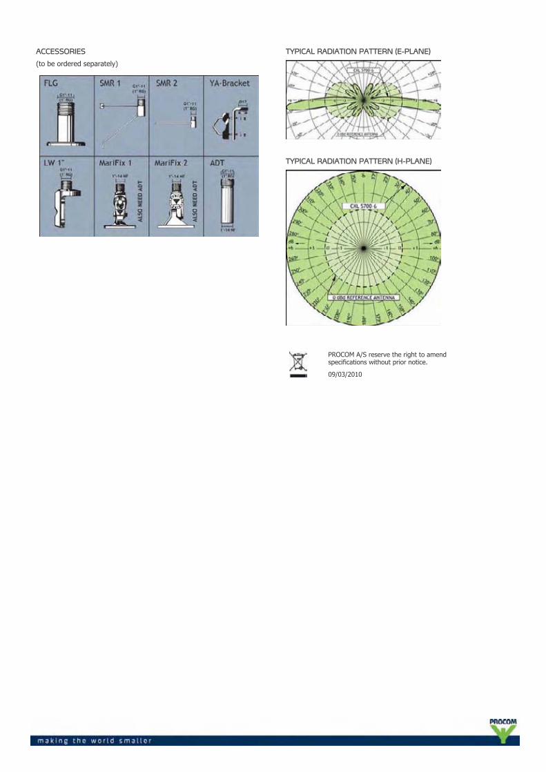
ACCESSORIES
(to be ordered separately)
TYPICAL RADIATION PATTERN (E-PLANE)
TYPICAL RADIATION PATTERN (H-PLANE)
PROCOM A/S reserve the right to amendspecifications without prior notice.
09/03/2010
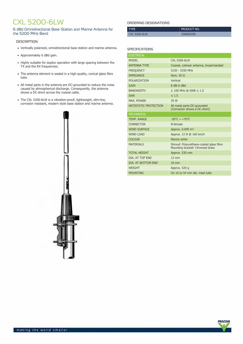
CXL 5200-6LW6 dBd Omnidirectional Base Station and Marine Antenna forthe 5200 MHz Band
DESCRIPTION
Vertically polarized, omnidirectional base station and marine antenna.
Approximately 6 dBd gain.
Highly suitable for duplex operation with large spacing between theTX and the RX frequencies.
The antenna element is sealed in a high-quality, conical glass fibretube.
All metal parts in the antenna are DC-grounded to reduce the noisecaused by atmospherical discharge. Consequently, the antennashows a DC-short across the coaxial cable.
The CXL 5200-6LW is a vibration-proof, lightweight, slim-line,corrosion resistant, modern style base station and marine antenna.
ORDERING DESIGNATIONS
TYPE PRODUCT NO.
CXL 5200-6LW 100000296
SPECIFICATIONS
ELECTRICAL
MODEL CXL 5200-6LW
ANTENNA TYPE Coaxial, colinear antenna, broad-banded
FREQUENCY 5150 - 5250 MHz
IMPEDANCE Nom. 50 Ω
POLARIZATION Vertical
GAIN 8 dBi 6 dBd
BANDWIDTH ≥ 100 MHz @ SWR ≤ 1.5
SWR ≤ 1.5
MAX. POWER 35 W
ANTISTATIC PROTECTION All metal parts DC-grounded(Connector shows a DC-short)
MECHANICAL
TEMP. RANGE -30°C → +70°C
CONNECTOR N-female
WIND SURFACE Approx. 0.009 m²
WIND LOAD Approx. 12 N @ 160 km/h
COLOUR Marine white
MATERIALS Shroud: Polyurethane-coated glass fibreMounting bracket: Chromed brass
TOTAL HEIGHT Approx. 530 mm
DIA. AT TOP END 13 mm
DIA. AT BOTTOM END 16 mm
WEIGHT Approx. 520 g
MOUNTING On 16 to 54 mm dia. mast tube
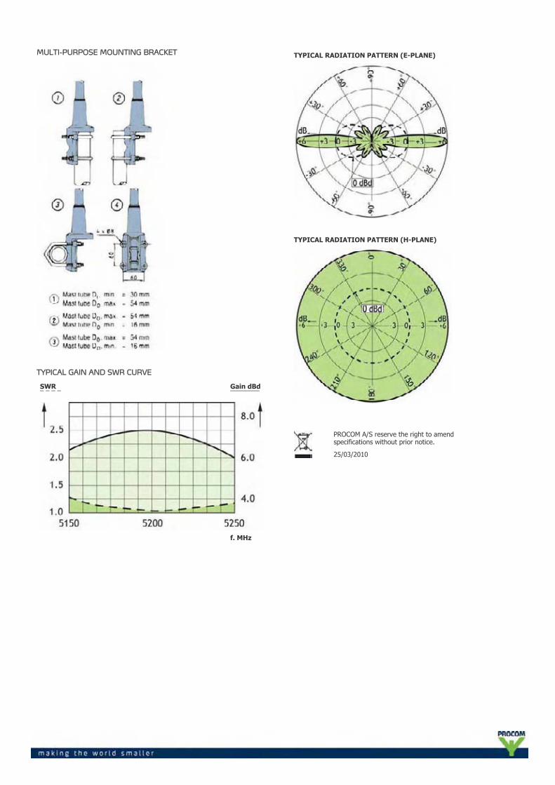
MULTI-PURPOSE MOUNTING BRACKET
TYPICAL GAIN AND SWR CURVE
SWR¯ ¯ ¯ ¯
Gain dBd¯¯¯¯¯¯¯¯
f. MHz
TYPICAL RADIATION PATTERN (E-PLANE)
TYPICAL RADIATION PATTERN (H-PLANE)
PROCOM A/S reserve the right to amendspecifications without prior notice.
25/03/2010
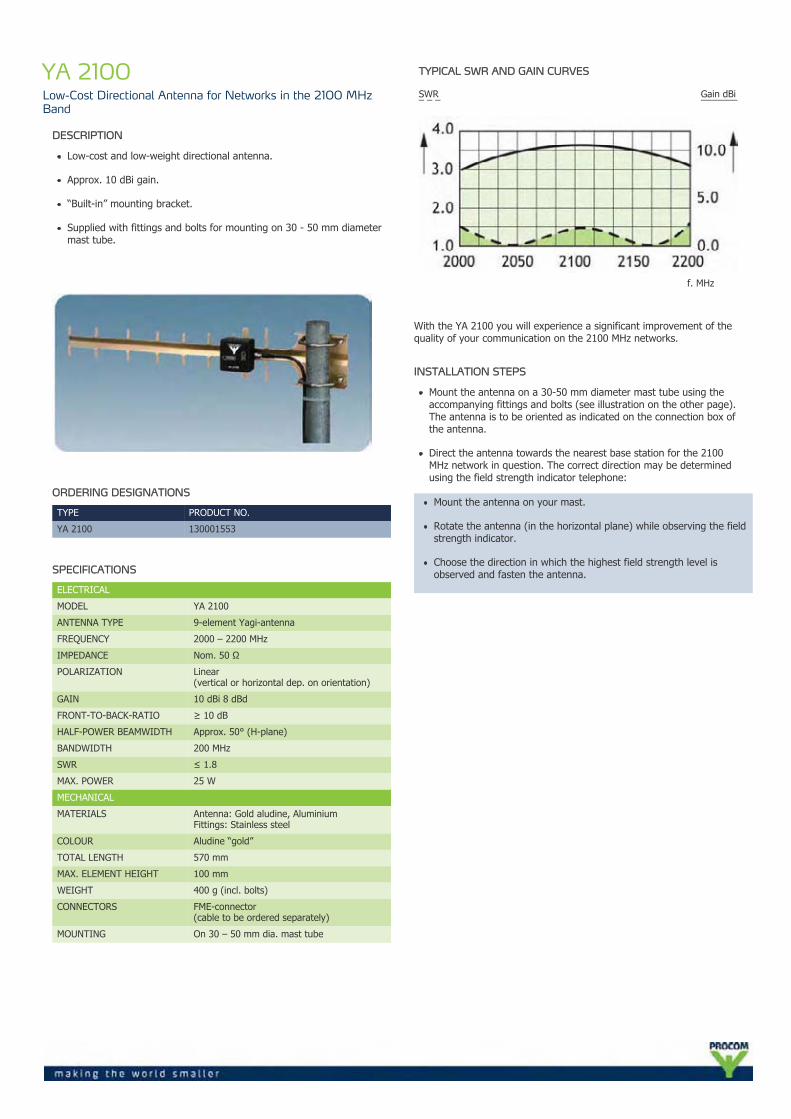
YA 2100Low-Cost Directional Antenna for Networks in the 2100 MHzBand
DESCRIPTION
Low-cost and low-weight directional antenna.
Approx. 10 dBi gain.
“Built-in” mounting bracket.
Supplied with fittings and bolts for mounting on 30 - 50 mm diametermast tube.
ORDERING DESIGNATIONS
TYPE PRODUCT NO.
YA 2100 130001553
SPECIFICATIONS
ELECTRICAL
MODEL YA 2100
ANTENNA TYPE 9-element Yagi-antenna
FREQUENCY 2000 – 2200 MHz
IMPEDANCE Nom. 50 Ω
POLARIZATION Linear(vertical or horizontal dep. on orientation)
GAIN 10 dBi 8 dBd
FRONT-TO-BACK-RATIO ≥ 10 dB
HALF-POWER BEAMWIDTH Approx. 50° (H-plane)
BANDWIDTH 200 MHz
SWR ≤ 1.8
MAX. POWER 25 W
MECHANICAL
MATERIALS Antenna: Gold aludine, AluminiumFittings: Stainless steel
COLOUR Aludine “gold”
TOTAL LENGTH 570 mm
MAX. ELEMENT HEIGHT 100 mm
WEIGHT 400 g (incl. bolts)
CONNECTORS FME-connector(cable to be ordered separately)
MOUNTING On 30 – 50 mm dia. mast tube
TYPICAL SWR AND GAIN CURVES
SWR¯ ¯ ¯
Gain dBi¯¯¯¯¯¯¯
f. MHz
With the YA 2100 you will experience a significant improvement of thequality of your communication on the 2100 MHz networks.
INSTALLATION STEPS
Mount the antenna on a 30-50 mm diameter mast tube using theaccompanying fittings and bolts (see illustration on the other page).The antenna is to be oriented as indicated on the connection box ofthe antenna.
Direct the antenna towards the nearest base station for the 2100MHz network in question. The correct direction may be determinedusing the field strength indicator telephone:
Mount the antenna on your mast.
Rotate the antenna (in the horizontal plane) while observing the fieldstrength indicator.
Choose the direction in which the highest field strength level isobserved and fasten the antenna.
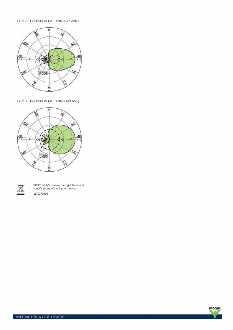
TYPICAL RADIATION PATTERN (E-PLANE)
TYPICAL RADIATION PATTERN (H-PLANE)
PROCOM A/S reserve the right to amendspecifications without prior notice.
16/03/2010
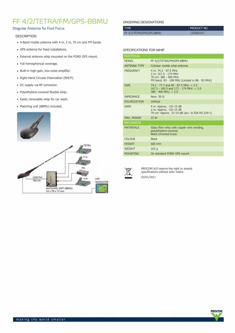
FF 4/2/TETRA/FM/GPS-BBMUDisguise Antenna for Ford Focus
DESCRIPTION
4-Band mobile antenna with 4 m, 2 m, 70 cm and FM bands.
GPS-antenna for fixed installations.
External antenna whip mounted on the FORD GPS mount.
Full hemispherical coverage.
Built-in high-gain, low-noise amplifier.
Right-Hand Circular Polarization (RHCP).
DC supply via RF-connector.
Polyethylene-covered flexible whip.
Easily removable whip for car wash.
Matching unit (BBMU) included.
ORDERING DESIGNATIONS
TYPE PRODUCT NO.
FF 4/2/TETRA/FM/GPS-BBMU 132000107
SPECIFICATIONS FOR WHIP
ELECTRICAL
MODEL FF 4/2/TETRA/FM/GPS-BBMU
ANTENNA TYPE Colinear mobile whip antenna
FREQUENCY 4 m: 74.2 - 87.5 MHz2 m: 167.5 - 174 MHz70 cm: 380 - 400 MHzFM band: 93 - 108 MHz (Limited in 88 - 93 MHz)
SWR 74.2 - 77.7 and 84 - 87.5 MHz: < 2.5167.5 - 169.5 and 172 - 174 MHz: < 2.0380 - 400 MHz: < 2.0
IMPEDANCE Nom. 50 Ω
POLARIZATION Vertical
GAIN 4 m: Approx. -10/-15 dB2 m: Approx. -10/-15 dB70 cm: Approx. -5/-10 dB (acc. to EIA RS-329-1)
MAX. POWER 25 W
MECHANICAL
MATERIALS Glass fibre whip with copper wire winding,polyethylene-covered.Black-chromed brass
COLOUR Black
HEIGHT 660 mm
WEIGHT 102 g
MOUNTING On standard FORD GPS mount
PROCOM A/S reserve the right to amendspecifications without prior notice.
03/01/2011
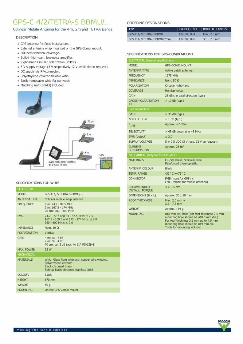
GPS-C 4/2/TETRA-S BBMU/...Colinear Mobile Antenna for the 4m, 2m and TETRA Bands
DESCRIPTION
GPS-antenna for fixed installations.External antenna whip mounted on the GPS-Combi mount.Full hemispherical coverage.Built-in high-gain, low-noise amplifier.Right-Hand Circular Polarization (RHCP).5 V supply voltage (3 V respectively 12 V available on request).DC supply via RF-connector.Polyethylene-covered flexible whip.Easily removable whip for car wash.Matching unit (BBMU) included.
SPECIFICATIONS FOR WHIP
ELECTRICAL
MODEL GPS-C 4/2/TETRA-S BBMU/...
ANTENNA TYPE Colinear mobile whip antenna
FREQUENCY 4 m: 74.2 - 87.5 MHz2 m: 167.5 - 174 MHz70 cm: 380 - 400 MHz
SWR 74.2 - 77.7 and 84 - 87.5 MHz: ≤ 2.5167.5 - 169.5 and 172 - 174 MHz: ≤ 2.0380 - 400 MHz: ≤ 2.0
IMPEDANCE Nom. 50 Ω
POLARIZATION Vertical
GAIN 4 m: ca. -2 dB2 m: ca. -4 dB70 cm: ca. 2 dB (acc. to EIA RS-329-1)
MAX. POWER 25 W
MECHANICAL
MATERIALS Whip: Glass fibre whip with copper wire winding,polyethylene-coveredBlack-chromed brassSpring: Black-chromed stainless steel
COLOUR Black
HEIGHT 670 mm
WEIGHT 60 g
MOUNTING On the GPS-Combi mount
ORDERING DESIGNATIONS
TYPE PRODUCT NO. ROOF THICKNESS
GPS-C 4/2/TETRA-S BBMU 132 000 084 Max. 2.0 mm
GPS-C 4/2/TETRA-S BBMU/7mm 132 000 096 3.5 - 7.5 mm
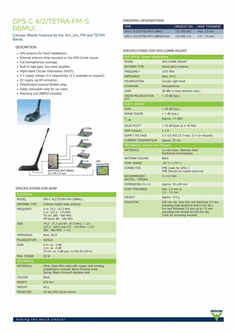
SPECIFICATIONS FOR GPS-COMBI MOUNT
ELECTRICAL General specifications
MODEL GPS-COMBI MOUNT
ANTENNA TYPE Active patch antenna
FREQUENCY 1575 MHz
IMPEDANCE Nom. 50 Ω
POLARIZATION Circular right-hand
COVERAGE Hemispherical
GAIN 28 dBic in axial direction (typ.)
CROSS-POLARIZATIONATT.
> 10 dB (typ.)
Built-in amplifier
GAIN > 30 dB (typ.)
NOISE FIGURE < 1 dB (typ.)
P1 dB Approx. +7 dBm
SELECTIVITY > 45 dB down at ± 45 MHz
SWR (output) ≤ 2.0
SUPPLY VOLTAGE 5 ± 0.5 VDC (3 V resp. 12 V on request)
CURRENTCONSUMPTION
Approx. 25 mA
MECHANICAL (only for the GPS-part)
MATERIALS Cu-nite brass. Stainless steelReinforced thermoplastic
ANTENNA COLOUR Black
TEMP. RANGE -35° C →+75° C
CONNECTOR FME (male for GPS) +FME (female for mobile antenna)
RECOMMENDEDINSTALL. TORQUE
4 ± 0.5 Nm
DIMENSIONS (H x L) Approx. 30 x 89 mm
ROOF THICKNESS Max. 2.0 mm or3.5 - 7.5 mm
WEIGHT Approx. 114 g
MOUNTING ø18 mm dia. hole (For roof thickness 2.5 mmmounting hole should be ø18.5 mm dia.)For roof thickness 3.5 mm up to 7.5 mmmounting hole should be ø19 mm dia.Tools for mounting included
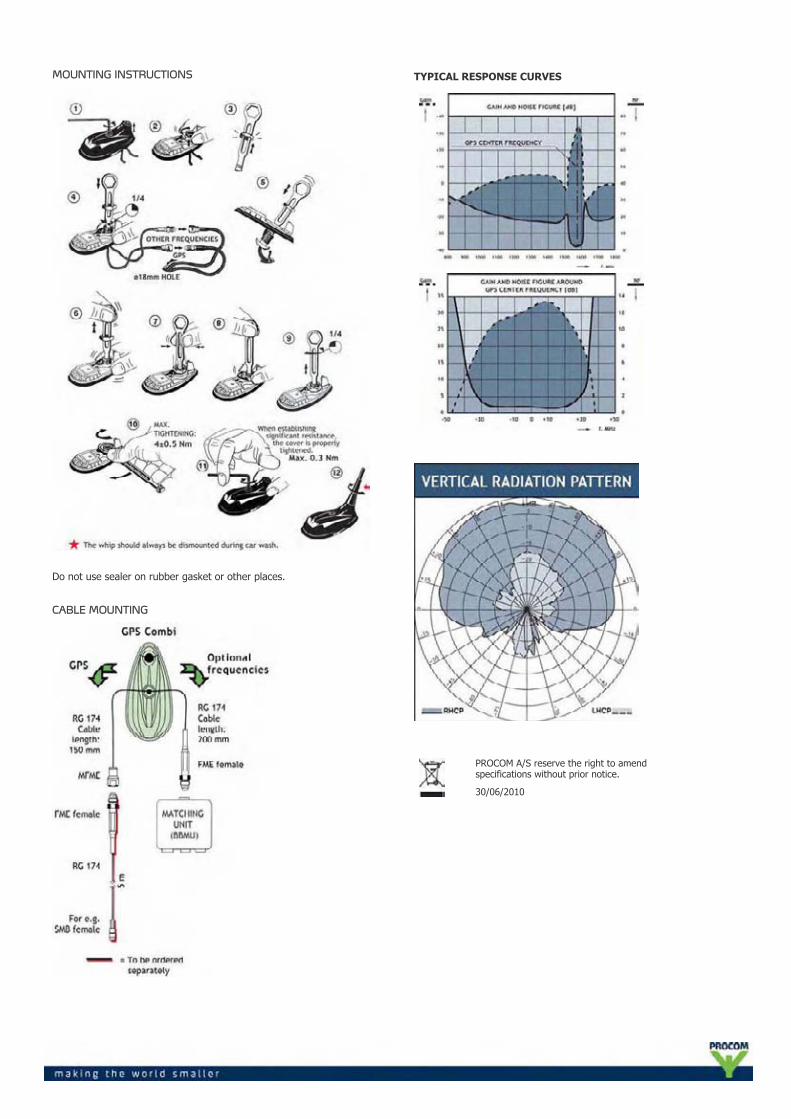
MOUNTING INSTRUCTIONS
Do not use sealer on rubber gasket or other places.
CABLE MOUNTING
TYPICAL RESPONSE CURVES
PROCOM A/S reserve the right to amendspecifications without prior notice.
30/06/2010
GPS-C 4/2/TETRA-FM-SBBMU/...Colinear Mobile Antenna for the 4m, 2m, FM and TETRABands
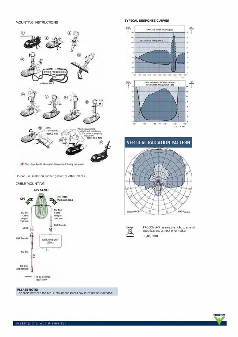
DESCRIPTION
GPS-antenna for fixed installations.External antenna whip mounted on the GPS-Combi mount.Full hemispherical coverage.Built-in high-gain, low-noise amplifier.Right-Hand Circular Polarization (RHCP).5 V supply voltage (3 V respectively 12 V available on request).DC supply via RF-connector.Polyethylene-covered flexible whip.Easily removable whip for car wash.Matching unit (BBMU) included.
SPECIFICATIONS FOR WHIP
ELECTRICAL
MODEL GPS-C 4/2/TETRA-FM-S BBMU/...
ANTENNA TYPE Colinear mobile whip antenna
FREQUENCY 4 m: 74.2 - 87.5 MHz2 m: 167.5 - 174 MHz70 cm: 380 - 400 MHzFM band: 88 - 108 MHz
SWR 74.2 - 77.7 and 84 - 87.5 MHz: < 2.5167.5 - 169.5 and 172 - 174 MHz: < 2.0380 - 400 MHz: < 2.0
IMPEDANCE Nom. 50 Ω
POLARIZATION Vertical
GAIN 4 m: ca. -3 dB2 m: ca. -4 dB70 cm: ca. 2 dB (acc. to EIA RS-329-1)
MAX. POWER 25 W
MECHANICAL
MATERIALS Whip: Glass fibre whip with copper wire winding,polyethylene-covered. Black-chromed brassSpring: Black-chromed stainless steel
COLOUR Black
HEIGHT 670 mm
WEIGHT 60 g
MOUNTING On the GPS-Combi mount
ORDERING DESIGNATIONS
TYPE PRODUCT NO. ROOF THICKNESS
GPS-C 4/2/TETRA-FM-S BBMU 132 000 090 Max. 2.0 mm
GPS-C 4/2/TETRA-FM-S BBMU/7mm 132 000 110 3.5 - 7.5 mm
SPECIFICATIONS FOR GPS-COMBI MOUNT
ELECTRICAL General specifications
MODEL GPS-COMBI MOUNT
ANTENNA TYPE Active patch antenna
FREQUENCY 1575 MHz
IMPEDANCE Nom. 50 Ω
POLARIZATION Circular right-hand
COVERAGE Hemispherical
GAIN 28 dBic in axial direction (typ.)
CROSS-POLARIZATIONATT.
> 10 dB (typ.)
Built-in amplifier
GAIN > 30 dB (typ.)
NOISE FIGURE < 1 dB (typ.)
P1 dB Approx. +7 dBm
SELECTIVITY > 45 dB down at ± 45 MHz
SWR (output) ≤ 2.0
SUPPLY VOLTAGE 5 ± 0.5 VDC (3 V resp. 12 V on request)
CURRENT CONSUMPTION Approx. 25 mA
MECHANICAL (only for the GPS-part)
MATERIALS Cu-nite brass. Stainless steelReinforced thermoplastic
ANTENNA COLOUR Black
TEMP. RANGE -35° C →+75° C
CONNECTOR FME (male for GPS) +FME (female for mobile antenna)
RECOMMENDEDINSTALL. TORQUE
4 ± 0.5 Nm
DIMENSIONS (H x L) Approx. 30 x 89 mm
ROOF THICKNESS Max. 2.0 mm or3.5 - 7.5 mm
WEIGHT Approx. 114 g
MOUNTING ø18 mm dia. hole (For roof thickness 2.5 mmmounting hole should be ø18.5 mm dia.)For roof thickness 3.5 mm up to 7.5 mmmounting hole should be ø19 mm dia.Tools for mounting included
MOUNTING INSTRUCTIONS
Do not use sealer on rubber gasket or other places.
CABLE MOUNTING
PLEASE NOTE:The cable between the GPS-C Mount and BBMU box must not be extended.
TYPICAL RESPONSE CURVES
PROCOM A/S reserve the right to amendspecifications without prior notice.
30/06/2010
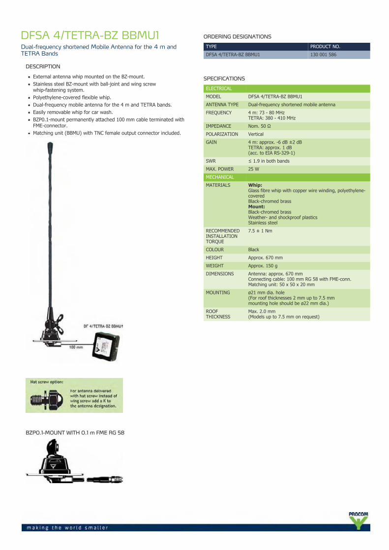
DFSA 4/TETRA-BZ BBMU1Dual-frequency shortened Mobile Antenna for the 4 m andTETRA Bands
DESCRIPTION
External antenna whip mounted on the BZ-mount.Stainless steel BZ-mount with ball-joint and wing screwwhip-fastening system.Polyethylene-covered flexible whip.Dual-frequency mobile antenna for the 4 m and TETRA bands.Easily removable whip for car wash.BZP0.1-mount permanently attached 100 mm cable terminated withFME-connector.Matching unit (BBMU) with TNC female output connector included.
BZP0.1-MOUNT WITH 0.1 m FME RG 58
ORDERING DESIGNATIONS
TYPE PRODUCT NO.
DFSA 4/TETRA-BZ BBMU1 130 001 586
SPECIFICATIONS
ELECTRICAL
MODEL DFSA 4/TETRA-BZ BBMU1
ANTENNA TYPE Dual-frequency shortened mobile antenna
FREQUENCY 4 m: 73 - 80 MHzTETRA: 380 - 410 MHz
IMPEDANCE Nom. 50 Ω
POLARIZATION Vertical
GAIN 4 m: approx. -6 dB ±2 dBTETRA: approx. 1 dB(acc. to EIA RS-329-1)
SWR ≤ 1.9 in both bands
MAX. POWER 25 W
MECHANICAL
MATERIALS Whip:Glass fibre whip with copper wire winding, polyethylene-coveredBlack-chromed brassMount:Black-chromed brassWeather- and shockproof plasticsStainless steel
RECOMMENDEDINSTALLATIONTORQUE
7.5 ± 1 Nm
COLOUR Black
HEIGHT Approx. 670 mm
WEIGHT Approx. 150 g
DIMENSIONS Antenna: approx. 670 mmConnecting cable: 100 mm RG 58 with FME-conn.Matching unit: 50 x 50 x 20 mm
MOUNTING ø21 mm dia. hole(For roof thicknesses 2 mm up to 7.5 mmmounting hole should be ø22 mm dia.)
ROOFTHICKNESS
Max. 2.0 mm(Models up to 7.5 mm on request)
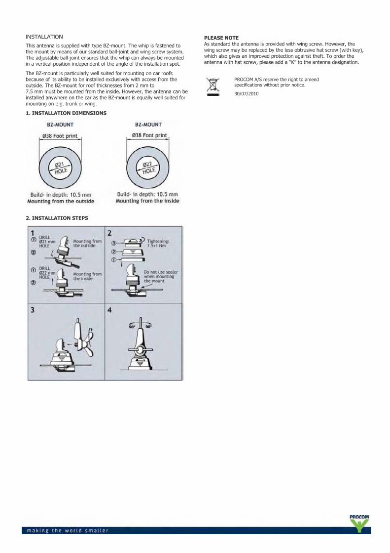
INSTALLATION
This antenna is supplied with type BZ-mount. The whip is fastened tothe mount by means of our standard ball-joint and wing screw system.The adjustable ball-joint ensures that the whip can always be mountedin a vertical position independent of the angle of the installation spot.
The BZ-mount is particularly well suited for mounting on car roofsbecause of its ability to be installed exclusively with access from theoutside. The BZ-mount for roof thicknesses from 2 mm to7.5 mm must be mounted from the inside. However, the antenna can beinstalled anywhere on the car as the BZ-mount is equally well suited formounting on e.g. trunk or wing.
1. INSTALLATION DIMENSIONS
2. INSTALLATION STEPS
PLEASE NOTEAs standard the antenna is provided with wing screw. However, thewing screw may be replaced by the less obtrusive hat screw (with key),which also gives an improved protection against theft. To order theantenna with hat screw, please add a “K” to the antenna designation.
PROCOM A/S reserve the right to amendspecifications without prior notice.
30/07/2010
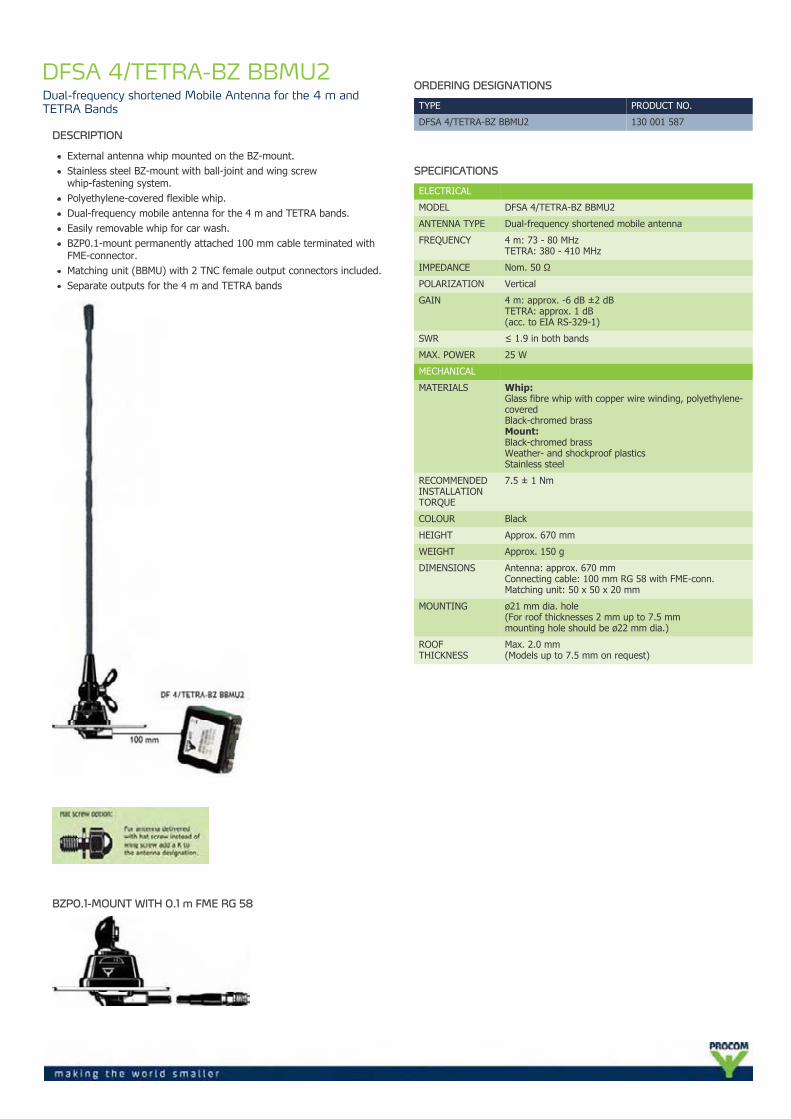
DFSA 4/TETRA-BZ BBMU2Dual-frequency shortened Mobile Antenna for the 4 m andTETRA Bands
DESCRIPTION
External antenna whip mounted on the BZ-mount.Stainless steel BZ-mount with ball-joint and wing screwwhip-fastening system.Polyethylene-covered flexible whip.Dual-frequency mobile antenna for the 4 m and TETRA bands.Easily removable whip for car wash.BZP0.1-mount permanently attached 100 mm cable terminated withFME-connector.Matching unit (BBMU) with 2 TNC female output connectors included.Separate outputs for the 4 m and TETRA bands
BZP0.1-MOUNT WITH 0.1 m FME RG 58
ORDERING DESIGNATIONS
TYPE PRODUCT NO.
DFSA 4/TETRA-BZ BBMU2 130 001 587
SPECIFICATIONS
ELECTRICAL
MODEL DFSA 4/TETRA-BZ BBMU2
ANTENNA TYPE Dual-frequency shortened mobile antenna
FREQUENCY 4 m: 73 - 80 MHzTETRA: 380 - 410 MHz
IMPEDANCE Nom. 50 Ω
POLARIZATION Vertical
GAIN 4 m: approx. -6 dB ±2 dBTETRA: approx. 1 dB(acc. to EIA RS-329-1)
SWR ≤ 1.9 in both bands
MAX. POWER 25 W
MECHANICAL
MATERIALS Whip:Glass fibre whip with copper wire winding, polyethylene-coveredBlack-chromed brassMount:Black-chromed brassWeather- and shockproof plasticsStainless steel
RECOMMENDEDINSTALLATIONTORQUE
7.5 ± 1 Nm
COLOUR Black
HEIGHT Approx. 670 mm
WEIGHT Approx. 150 g
DIMENSIONS Antenna: approx. 670 mmConnecting cable: 100 mm RG 58 with FME-conn.Matching unit: 50 x 50 x 20 mm
MOUNTING ø21 mm dia. hole(For roof thicknesses 2 mm up to 7.5 mmmounting hole should be ø22 mm dia.)
ROOFTHICKNESS
Max. 2.0 mm(Models up to 7.5 mm on request)

INSTALLATION
This antenna is supplied with type BZ-mount. The whip is fastened tothe mount by means of our standard ball-joint and wing screw system.The adjustable ball-joint ensures that the whip can always be mountedin a vertical position independent of the angle of the installation spot.
The BZ-mount is particularly well suited for mounting on car roofsbecause of its ability to be installed exclusively with access from theoutside. The BZ-mount for roof thicknesses from 2 mm to7.5 mm must be mounted from the inside. However, the antenna can beinstalled anywhere on the car as the BZ-mount is equally well suited formounting on e.g. trunk or wing.
1. INSTALLATION DIMENSIONS
2. INSTALLATION STEPS
PLEASE NOTEAs standard the antenna is provided with wing screw. However, thewing screw may be replaced by the less obtrusive hat screw (with key),which also gives an improved protection against theft. To order theantenna with hat screw, please add a “K” to the antenna designation.
PROCOM A/S reserve the right to amendspecifications without prior notice.
02/08/2010
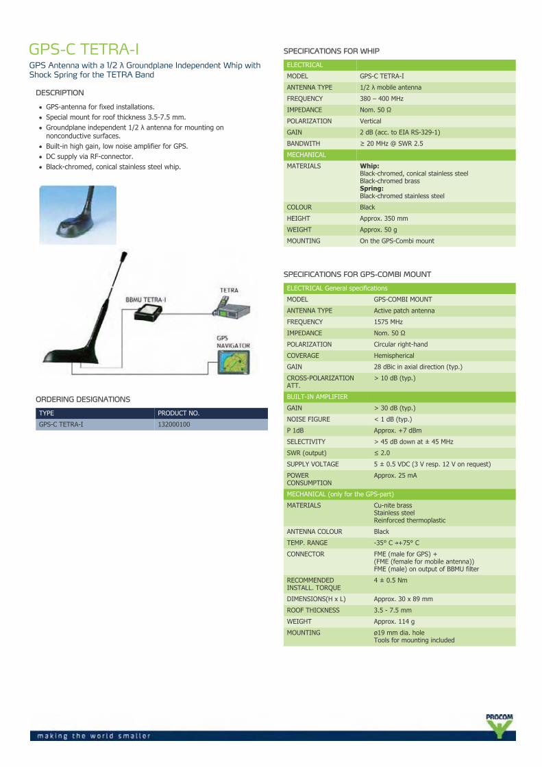
GPS-C TETRA-IGPS Antenna with a 1/2 λ Groundplane Independent Whip withShock Spring for the TETRA Band
DESCRIPTION
GPS-antenna for fixed installations.Special mount for roof thickness 3.5-7.5 mm.Groundplane independent 1/2 λ antenna for mounting onnonconductive surfaces.Built-in high gain, low noise amplifier for GPS.DC supply via RF-connector.Black-chromed, conical stainless steel whip.
ORDERING DESIGNATIONS
TYPE PRODUCT NO.
GPS-C TETRA-I 132000100
SPECIFICATIONS FOR WHIP
ELECTRICAL
MODEL GPS-C TETRA-I
ANTENNA TYPE 1/2 λ mobile antenna
FREQUENCY 380 – 400 MHz
IMPEDANCE Nom. 50 Ω
POLARIZATION Vertical
GAIN 2 dB (acc. to EIA RS-329-1)
BANDWITH ≥ 20 MHz @ SWR 2.5
MECHANICAL
MATERIALS Whip:Black-chromed, conical stainless steelBlack-chromed brassSpring:Black-chromed stainless steel
COLOUR Black
HEIGHT Approx. 350 mm
WEIGHT Approx. 50 g
MOUNTING On the GPS-Combi mount
SPECIFICATIONS FOR GPS-COMBI MOUNT
ELECTRICAL General specifications
MODEL GPS-COMBI MOUNT
ANTENNA TYPE Active patch antenna
FREQUENCY 1575 MHz
IMPEDANCE Nom. 50 Ω
POLARIZATION Circular right-hand
COVERAGE Hemispherical
GAIN 28 dBic in axial direction (typ.)
CROSS-POLARIZATIONATT.
> 10 dB (typ.)
BUILT-IN AMPLIFIER
GAIN > 30 dB (typ.)
NOISE FIGURE < 1 dB (typ.)
P 1dB Approx. +7 dBm
SELECTIVITY > 45 dB down at ± 45 MHz
SWR (output) ≤ 2.0
SUPPLY VOLTAGE 5 ± 0.5 VDC (3 V resp. 12 V on request)
POWERCONSUMPTION
Approx. 25 mA
MECHANICAL (only for the GPS-part)
MATERIALS Cu-nite brassStainless steelReinforced thermoplastic
ANTENNA COLOUR Black
TEMP. RANGE -35° C →+75° C
CONNECTOR FME (male for GPS) +(FME (female for mobile antenna))FME (male) on output of BBMU filter
RECOMMENDEDINSTALL. TORQUE
4 ± 0.5 Nm
DIMENSIONS(H x L) Approx. 30 x 89 mm
ROOF THICKNESS 3.5 - 7.5 mm
WEIGHT Approx. 114 g
MOUNTING ø19 mm dia. holeTools for mounting included
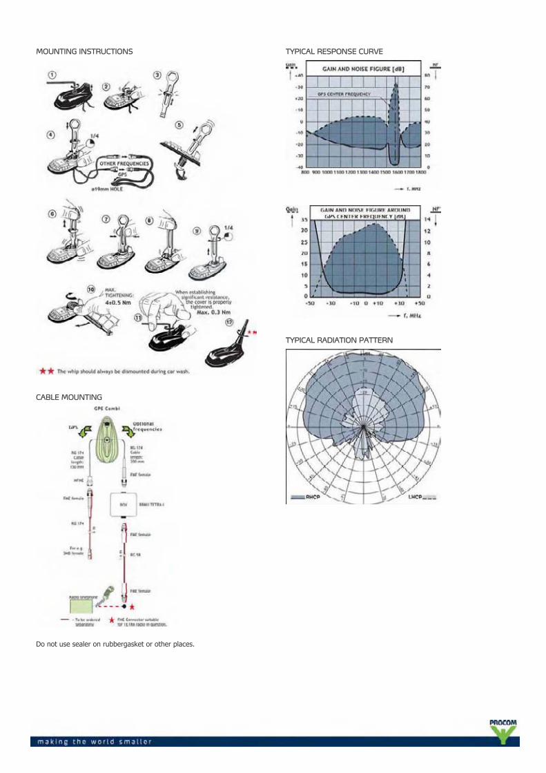
MOUNTING INSTRUCTIONS
CABLE MOUNTING
Do not use sealer on rubbergasket or other places.
TYPICAL RESPONSE CURVE
TYPICAL RADIATION PATTERN

TUNING
SWR 3000 Analyzer with built-in signal generator andgraphic display range of measurement 30-2700 MHz.
Tune the SWR in on the desired centre frequencyand suitable spacing (for instance 30 MHz).Adjust C1 till the SWR curve emerges on thedisplay. Adjust C2 till the best possible SWRminimum is reached on the required frequency.Fine-tune the SWR minimum and the bandwidthstep by step by means of C1 and C2.
PROCOM A/S reserve the right to amendspecifications without prior notice.
16/02/2010
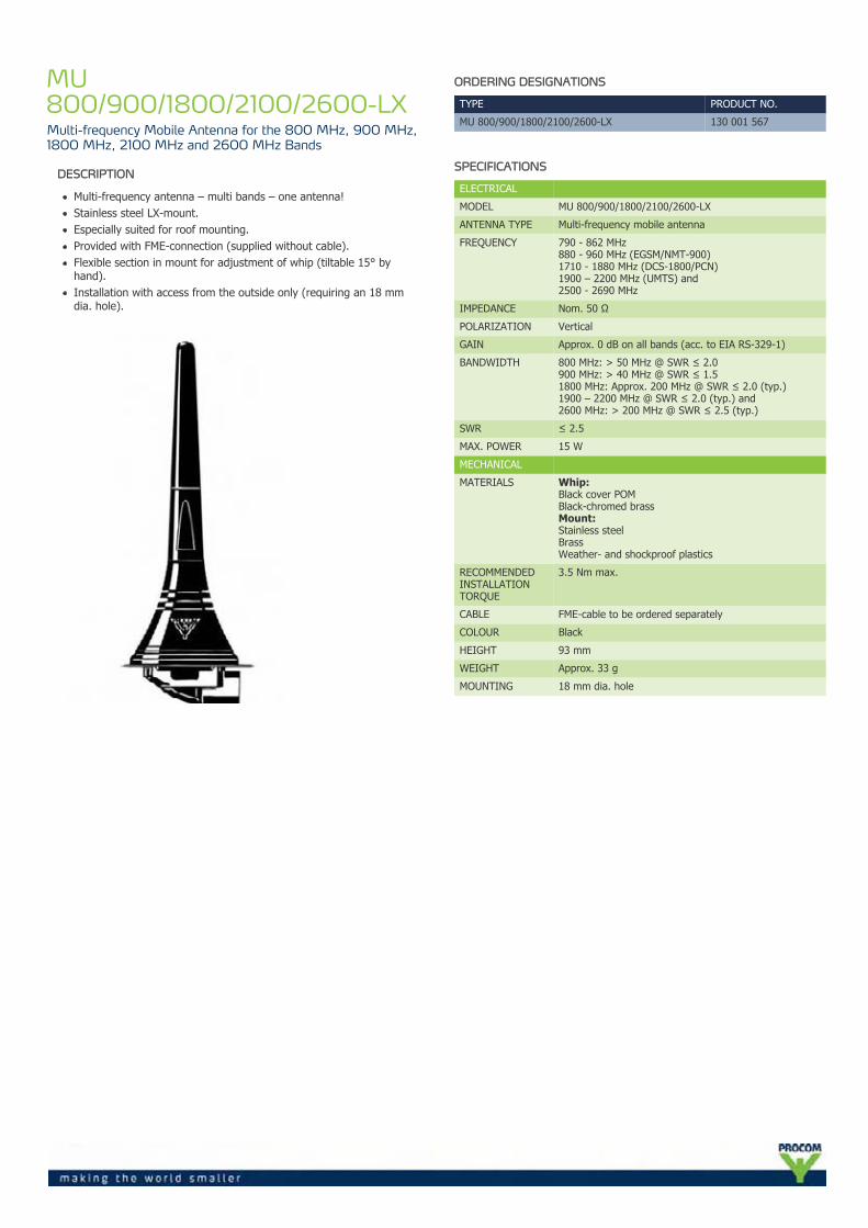
MU800/900/1800/2100/2600-LXMulti-frequency Mobile Antenna for the 800 MHz, 900 MHz,1800 MHz, 2100 MHz and 2600 MHz Bands
DESCRIPTION
Multi-frequency antenna – multi bands – one antenna!Stainless steel LX-mount.Especially suited for roof mounting.Provided with FME-connection (supplied without cable).Flexible section in mount for adjustment of whip (tiltable 15° byhand).Installation with access from the outside only (requiring an 18 mmdia. hole).
ORDERING DESIGNATIONS
TYPE PRODUCT NO.
MU 800/900/1800/2100/2600-LX 130 001 567
SPECIFICATIONS
ELECTRICAL
MODEL MU 800/900/1800/2100/2600-LX
ANTENNA TYPE Multi-frequency mobile antenna
FREQUENCY 790 - 862 MHz880 - 960 MHz (EGSM/NMT-900)1710 - 1880 MHz (DCS-1800/PCN)1900 – 2200 MHz (UMTS) and2500 - 2690 MHz
IMPEDANCE Nom. 50 Ω
POLARIZATION Vertical
GAIN Approx. 0 dB on all bands (acc. to EIA RS-329-1)
BANDWIDTH 800 MHz: > 50 MHz @ SWR ≤ 2.0900 MHz: > 40 MHz @ SWR ≤ 1.51800 MHz: Approx. 200 MHz @ SWR ≤ 2.0 (typ.)1900 – 2200 MHz @ SWR ≤ 2.0 (typ.) and2600 MHz: > 200 MHz @ SWR ≤ 2.5 (typ.)
SWR ≤ 2.5
MAX. POWER 15 W
MECHANICAL
MATERIALS Whip:Black cover POMBlack-chromed brassMount:Stainless steelBrassWeather- and shockproof plastics
RECOMMENDEDINSTALLATIONTORQUE
3.5 Nm max.
CABLE FME-cable to be ordered separately
COLOUR Black
HEIGHT 93 mm
WEIGHT Approx. 33 g
MOUNTING 18 mm dia. hole
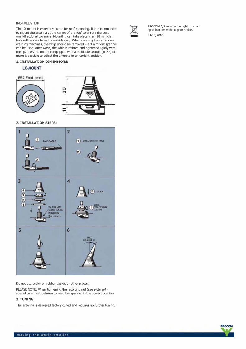
INSTALLATION
The LX-mount is especially suited for roof-mounting. It is recommendedto mount the antenna at the centre of the roof to ensure the bestomnidirectional coverage. Mounting can take place in an 18 mm dia.hole with access from the outside only. When cleaning the car in car-washing machines, the whip should be removed – a 9 mm fork spannercan be used. After wash, the whip is refitted and tightened lightly withthe spanner.The mount is equipped with a bendable section (±15°) tomake it possible to adjust the antenna to an upright position.
1. INSTALLATION DIMENSIONS:
2. INSTALLATION STEPS:
Do not use sealer on rubber gasket or other places.
PLEASE NOTE: When tightening the revolving nut (see picture 4),special care must betaken to keep the spanner in the correct position.
3. TUNING:
The antenna is delivered factory-tuned and requires no further tuning.
PROCOM A/S reserve the right to amendspecifications without prior notice.
21/12/2010
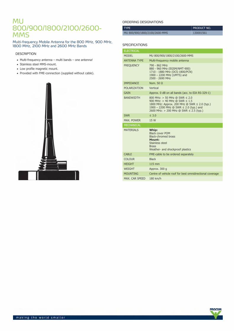
MU800/900/1800/2100/2600-MMSMulti-frequency Mobile Antenna for the 800 MHz, 900 MHz,1800 MHz, 2100 MHz and 2600 MHz Bands
DESCRIPTION
Multi-frequency antenna – multi bands – one antenna!Stainless steel MMS-mount.Low profile magnetic mount.Provided with FME-connection (supplied without cable).
ORDERING DESIGNATIONS
TYPE PRODUCT NO.
MU 800/900/1800/2100/2600-MMS 130001561
SPECIFICATIONS
ELECTRICAL
MODEL MU 800/900/1800/2100/2600-MMS
ANTENNA TYPE Multi-frequency mobile antenna
FREQUENCY 790 - 862 MHz880 - 960 MHz (EGSM/NMT-900)1710 - 1880 MHz (DCS-1800/PCN)1900 – 2200 MHz (UMTS) and2500 - 2690 MHz
IMPEDANCE Nom. 50 Ω
POLARIZATION Vertical
GAIN Approx. 0 dB on all bands (acc. to EIA RS-329-1)
BANDWIDTH 800 MHz: > 50 MHz @ SWR ≤ 2.0900 MHz: > 40 MHz @ SWR ≤ 1.51800 MHz: Approx. 200 MHz @ SWR ≤ 2.0 (typ.)1900 – 2200 MHz @ SWR ≤ 2.0 (typ.) and2600 MHz: > 200 MHz @ SWR ≤ 2.5 (typ.)
SWR ≤ 3.0
MAX. POWER 15 W
MECHANICAL
MATERIALS Whip:Black cover POMBlack-chromed brassMount:Stainless steelBrassWeather- and shockproof plastics
CABLE FME-cable to be ordered separately
COLOUR Black
HEIGHT 115 mm
WEIGHT Approx. 300 g
MOUNTING Centre of vehicle roof for best omnidirectional coverage
MAX. CAR SPEED 180 km/h
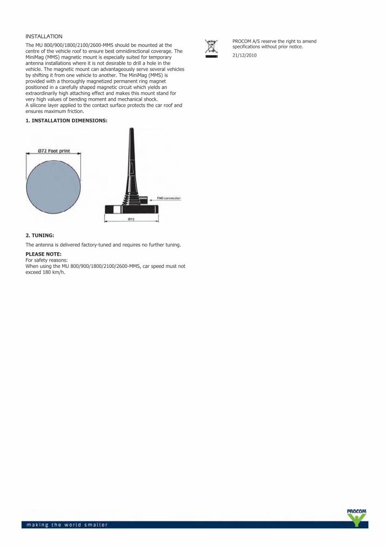
INSTALLATION
The MU 800/900/1800/2100/2600-MMS should be mounted at thecentre of the vehicle roof to ensure best omnidirectional coverage. TheMiniMag (MMS) magnetic mount is especially suited for temporaryantenna installations where it is not desirable to drill a hole in thevehicle. The magnetic mount can advantageously serve several vehiclesby shifting it from one vehicle to another. The MiniMag (MMS) isprovided with a thoroughly magnetized permanent ring magnetpositioned in a carefully shaped magnetic circuit which yields anextraordinarily high attaching effect and makes this mount stand forvery high values of bending moment and mechanical shock.A silicone layer applied to the contact surface protects the car roof andensures maximum friction.
1. INSTALLATION DIMENSIONS:
2. TUNING:
The antenna is delivered factory-tuned and requires no further tuning.
PLEASE NOTE:For safety reasons:When using the MU 800/900/1800/2100/2600-MMS, car speed must notexceed 180 km/h.
PROCOM A/S reserve the right to amendspecifications without prior notice.
21/12/2010
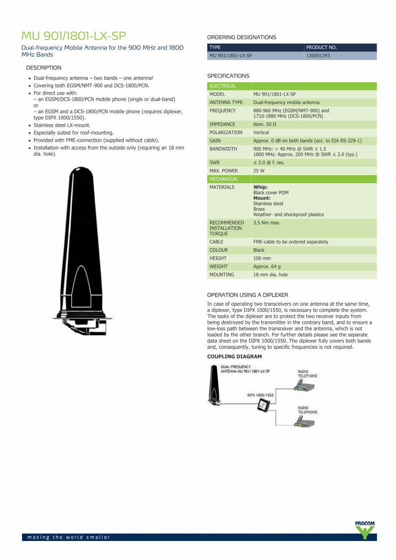
MU 901/1801-LX-SPDual-frequency Mobile Antenna for the 900 MHz and 1800MHz Bands
DESCRIPTION
Dual-frequency antenna – two bands – one antenna!Covering both EGSM/NMT-900 and DCS-1800/PCN.For direct use with:– an EGSM/DCS-1800/PCN mobile phone (single or dual-band)or– an EGSM and a DCS-1800/PCN mobile phone (requires diplexer,type DIPX 1000/1550).Stainless steel LX-mount.Especially suited for roof-mounting.Provided with FME-connection (supplied without cable).Installation with access from the outside only (requiring an 18 mmdia. hole).
ORDERING DESIGNATIONS
TYPE PRODUCT NO.
MU 901/1801-LX-SP 130001343
SPECIFICATIONS
ELECTRICAL
MODEL MU 901/1801-LX-SP
ANTENNA TYPE Dual-frequency mobile antenna
FREQUENCY 880-960 MHz (EGSM/NMT-900) and1710-1880 MHz (DCS-1800/PCN)
IMPEDANCE Nom. 50 Ω
POLARIZATION Vertical
GAIN Approx. 0 dB on both bands (acc. to EIA RS-329-1)
BANDWIDTH 900 MHz: > 40 MHz @ SWR ≤ 1.51800 MHz: Approx. 200 MHz @ SWR ≤ 2.0 (typ.)
SWR ≤ 2.0 @ f. res.
MAX. POWER 25 W
MECHANICAL
MATERIALS Whip:Black cover POMMount:Stainless steelBrassWeather- and shockproof plastics
RECOMMENDEDINSTALLATIONTORQUE
3.5 Nm max.
CABLE FME-cable to be ordered separately
COLOUR Black
HEIGHT 100 mm
WEIGHT Approx. 64 g
MOUNTING 18 mm dia. hole
OPERATION USING A DIPLEXER
In case of operating two transceivers on one antenna at the same time,a diplexer, type DIPX 1000/1550, is necessary to complete the system.The tasks of the diplexer are to protect the two receiver inputs frombeing destroyed by the transmitter in the contrary band, and to ensure alow-loss path between the transceiver and the antenna, which is notloaded by the other branch. For further details please see the separatedata sheet on the DIPX 1000/1550. The diplexer fully covers both bandsand, consequently, tuning to specific frequencies is not required.
COUPLING DIAGRAM
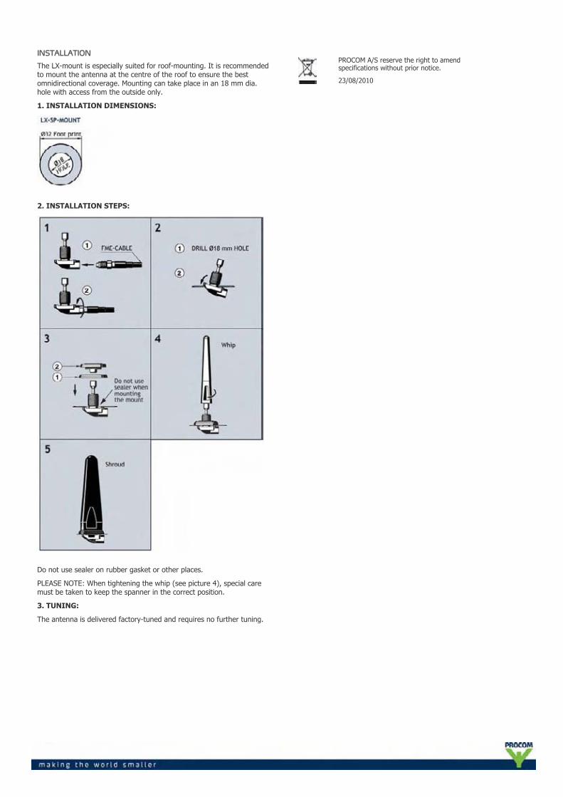
INSTALLATION
The LX-mount is especially suited for roof-mounting. It is recommendedto mount the antenna at the centre of the roof to ensure the bestomnidirectional coverage. Mounting can take place in an 18 mm dia.hole with access from the outside only.
1. INSTALLATION DIMENSIONS:
2. INSTALLATION STEPS:
Do not use sealer on rubber gasket or other places.
PLEASE NOTE: When tightening the whip (see picture 4), special caremust be taken to keep the spanner in the correct position.
3. TUNING:
The antenna is delivered factory-tuned and requires no further tuning.
PROCOM A/S reserve the right to amendspecifications without prior notice.
23/08/2010
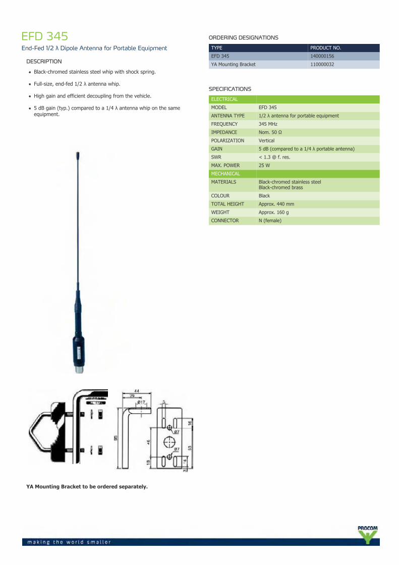
EFD 345End-Fed 1/2 λ Dipole Antenna for Portable Equipment
DESCRIPTION
Black-chromed stainless steel whip with shock spring.
Full-size, end-fed 1/2 λ antenna whip.
High gain and efficient decoupling from the vehicle.
5 dB gain (typ.) compared to a 1/4 λ antenna whip on the sameequipment.
YA Mounting Bracket to be ordered separately.
ORDERING DESIGNATIONS
TYPE PRODUCT NO.
EFD 345 140000156
YA Mounting Bracket 110000032
SPECIFICATIONS
ELECTRICAL
MODEL EFD 345
ANTENNA TYPE 1/2 λ antenna for portable equipment
FREQUENCY 345 MHz
IMPEDANCE Nom. 50 Ω
POLARIZATION Vertical
GAIN 5 dB (compared to a 1/4 λ portable antenna)
SWR < 1.3 @ f. res.
MAX. POWER 25 W
MECHANICAL
MATERIALS Black-chromed stainless steelBlack-chromed brass
COLOUR Black
TOTAL HEIGHT Approx. 440 mm
WEIGHT Approx. 160 g
CONNECTOR N (female)
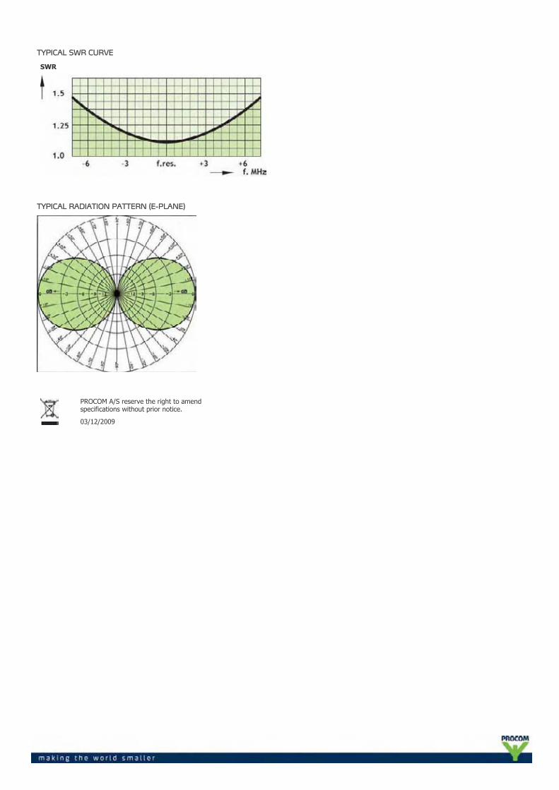
TYPICAL SWR CURVE
SWR
TYPICAL RADIATION PATTERN (E-PLANE)
PROCOM A/S reserve the right to amendspecifications without prior notice.
03/12/2009
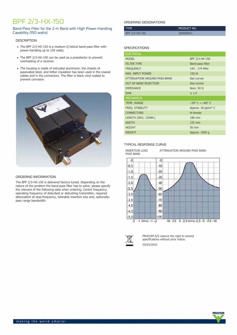
BPF 2/3-HX-150Band-Pass Filter for the 2 m Band with High Power-HandlingCapability (150 watts)
DESCRIPTION
The BPF 2/3-HX-150 is a medium Q helical band-pass filter withpower-handling up to 150 watts.
The BPF 2/3-HX-150 can be used as a preselector to preventoverloading of a receiver.
The housing is made of extruded aluminium, the chassis ofpassivated steel, and teflon insulation has been used in the coaxialcables and in the connectors. The filter is black vinyl coated toprevent corrosion.
ORDERING INFORMATION
The BPF 2/3-HX-150 is delivered factory-tuned. Depending on thenature of the problem the band-pass filter has to solve, please specifythe relevant of the following data when ordering: Centre frequency,operating frequency of disturbed or disturbing transmitter, requiredattenuation at stop-frequency, tolerable insertion loss and, optionally:pass range bandwidth.
ORDERING DESIGNATIONS
TYPE PRODUCT NO.
BPF 2/3-HX-150 200000821
SPECIFICATIONS
ELECTRICAL
MODEL BPF 2/3-HX-150
FILTER TYPE Band-pass filter
FREQUENCY 145 - 174 MHz
MAX. INPUT POWER 150 W
ATTENUATION AROUND PASS-BAND See curves
OUT OF BAND REJECTION See curves
IMPEDANCE Nom. 50 Ω
SWR ≤ 1.4
MECHANICAL
TEMP. RANGE –30° C → +60° C
FREQ. STABILITY Approx. 18 ppm/° C
CONNECTORS N-female
LENGTH (INCL. CONN.) 186 mm
WIDTH 125 mm
HEIGHT 50 mm
WEIGHT Approx. 1050 g
TYPICAL RESPONSE CURVE
INSERTION LOSSPASS BAND
ATTENUATION AROUND PASS BAND
PROCOM A/S reserve the right to amendspecifications without prior notice.
25/03/2010
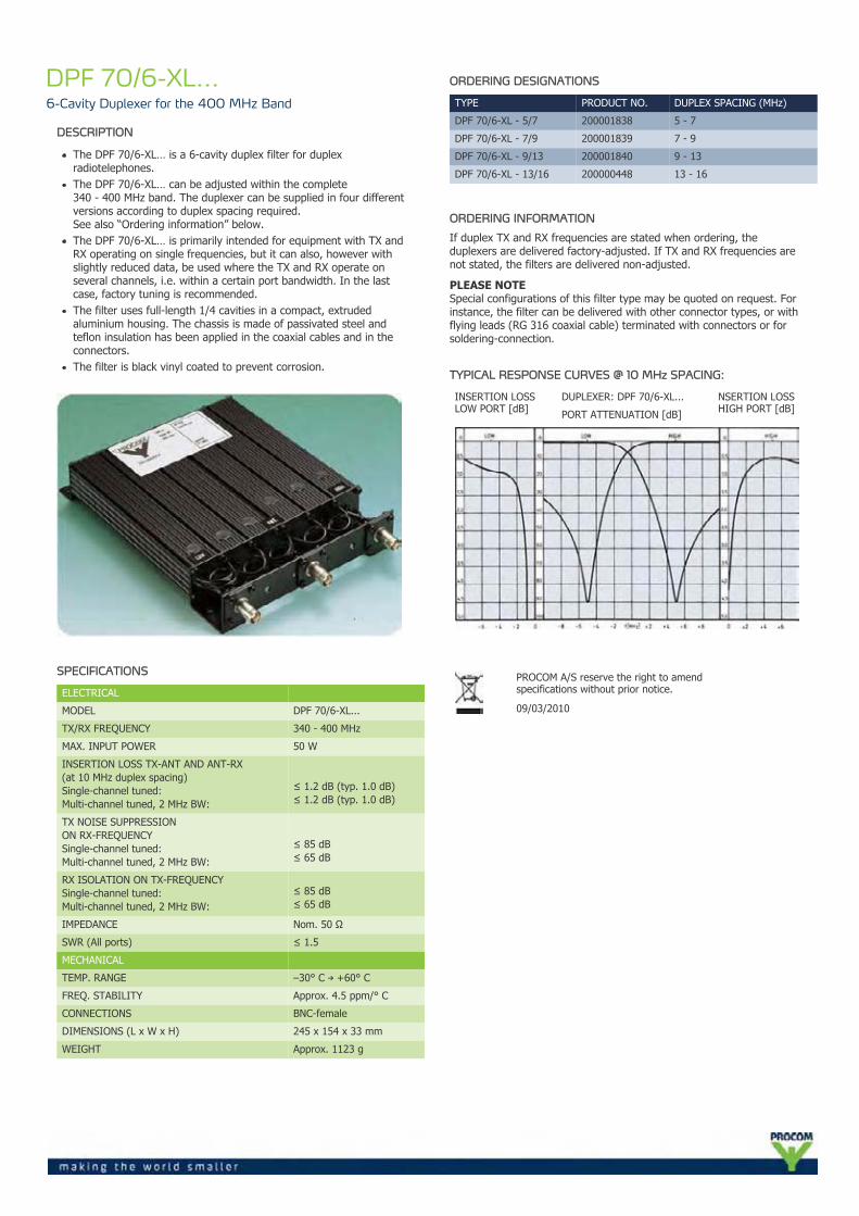
DPF 70/6-XL...6-Cavity Duplexer for the 400 MHz Band
DESCRIPTION
The DPF 70/6-XL… is a 6-cavity duplex filter for duplexradiotelephones.The DPF 70/6-XL… can be adjusted within the complete340 - 400 MHz band. The duplexer can be supplied in four differentversions according to duplex spacing required.See also “Ordering information” below.The DPF 70/6-XL… is primarily intended for equipment with TX andRX operating on single frequencies, but it can also, however withslightly reduced data, be used where the TX and RX operate onseveral channels, i.e. within a certain port bandwidth. In the lastcase, factory tuning is recommended.The filter uses full-length 1/4 cavities in a compact, extrudedaluminium housing. The chassis is made of passivated steel andteflon insulation has been applied in the coaxial cables and in theconnectors.The filter is black vinyl coated to prevent corrosion.
SPECIFICATIONS
ELECTRICAL
MODEL DPF 70/6-XL...
TX/RX FREQUENCY 340 - 400 MHz
MAX. INPUT POWER 50 W
INSERTION LOSS TX-ANT AND ANT-RX(at 10 MHz duplex spacing)Single-channel tuned:Multi-channel tuned, 2 MHz BW:
≤ 1.2 dB (typ. 1.0 dB)≤ 1.2 dB (typ. 1.0 dB)
TX NOISE SUPPRESSIONON RX-FREQUENCYSingle-channel tuned:Multi-channel tuned, 2 MHz BW:
≤ 85 dB≤ 65 dB
RX ISOLATION ON TX-FREQUENCYSingle-channel tuned:Multi-channel tuned, 2 MHz BW:
≤ 85 dB≤ 65 dB
IMPEDANCE Nom. 50 Ω
SWR (All ports) ≤ 1.5
MECHANICAL
TEMP. RANGE –30° C → +60° C
FREQ. STABILITY Approx. 4.5 ppm/° C
CONNECTIONS BNC-female
DIMENSIONS (L x W x H) 245 x 154 x 33 mm
WEIGHT Approx. 1123 g
ORDERING DESIGNATIONS
TYPE PRODUCT NO. DUPLEX SPACING (MHz)
DPF 70/6-XL - 5/7 200001838 5 - 7
DPF 70/6-XL - 7/9 200001839 7 - 9
DPF 70/6-XL - 9/13 200001840 9 - 13
DPF 70/6-XL - 13/16 200000448 13 - 16
ORDERING INFORMATION
If duplex TX and RX frequencies are stated when ordering, theduplexers are delivered factory-adjusted. If TX and RX frequencies arenot stated, the filters are delivered non-adjusted.
PLEASE NOTESpecial configurations of this filter type may be quoted on request. Forinstance, the filter can be delivered with other connector types, or withflying leads (RG 316 coaxial cable) terminated with connectors or forsoldering-connection.
TYPICAL RESPONSE CURVES @ 10 MHz SPACING:
INSERTION LOSSLOW PORT [dB]
DUPLEXER: DPF 70/6-XL... NSERTION LOSSHIGH PORT [dB]PORT ATTENUATION [dB]
PROCOM A/S reserve the right to amendspecifications without prior notice.
09/03/2010
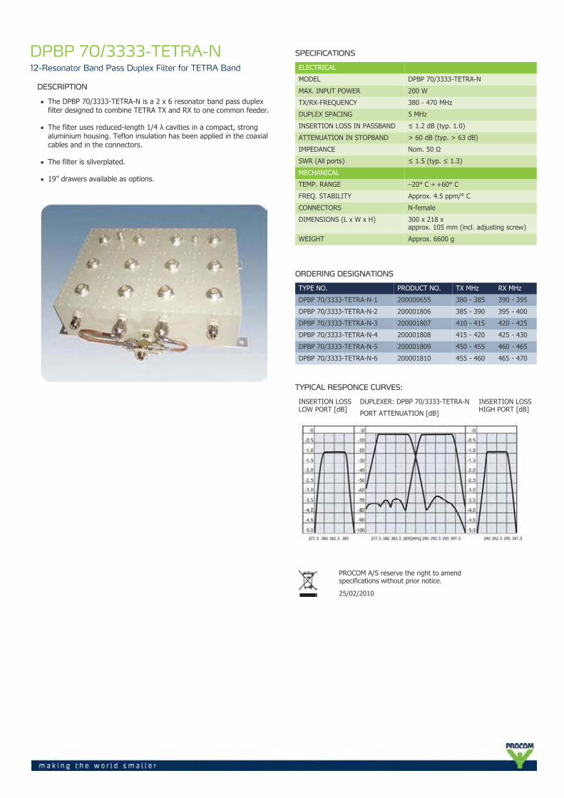
DPBP 70/3333-TETRA-N12-Resonator Band Pass Duplex Filter for TETRA Band
DESCRIPTION
The DPBP 70/3333-TETRA-N is a 2 x 6 resonator band pass duplexfilter designed to combine TETRA TX and RX to one common feeder.
The filter uses reduced-length 1/4 λ cavities in a compact, strongaluminium housing. Teflon insulation has been applied in the coaxialcables and in the connectors.
The filter is silverplated.
19” drawers available as options.
SPECIFICATIONS
ELECTRICAL
MODEL DPBP 70/3333-TETRA-N
MAX. INPUT POWER 200 W
TX/RX-FREQUENCY 380 - 470 MHz
DUPLEX SPACING 5 MHz
INSERTION LOSS IN PASSBAND ≤ 1.2 dB (typ. 1.0)
ATTENUATION IN STOPBAND > 60 dB (typ. > 63 dB)
IMPEDANCE Nom. 50 Ω
SWR (All ports) ≤ 1.5 (typ. ≤ 1.3)
MECHANICAL
TEMP. RANGE –20° C → +60° C
FREQ. STABILITY Approx. 4.5 ppm/° C
CONNECTORS N-female
DIMENSIONS (L x W x H) 300 x 218 xapprox. 105 mm (incl. adjusting screw)
WEIGHT Approx. 6600 g
ORDERING DESIGNATIONS
TYPE NO. PRODUCT NO. TX MHz RX MHz
DPBP 70/3333-TETRA-N-1 200000655 380 - 385 390 - 395
DPBP 70/3333-TETRA-N-2 200001806 385 - 390 395 - 400
DPBP 70/3333-TETRA-N-3 200001807 410 - 415 420 - 425
DPBP 70/3333-TETRA-N-4 200001808 415 - 420 425 - 430
DPBP 70/3333-TETRA-N-5 200001809 450 - 455 460 - 465
DPBP 70/3333-TETRA-N-6 200001810 455 - 460 465 - 470
TYPICAL RESPONCE CURVES:
INSERTION LOSSLOW PORT [dB]
DUPLEXER: DPBP 70/3333-TETRA-N INSERTION LOSSHIGH PORT [dB]PORT ATTENUATION [dB]
PROCOM A/S reserve the right to amendspecifications without prior notice.
25/02/2010
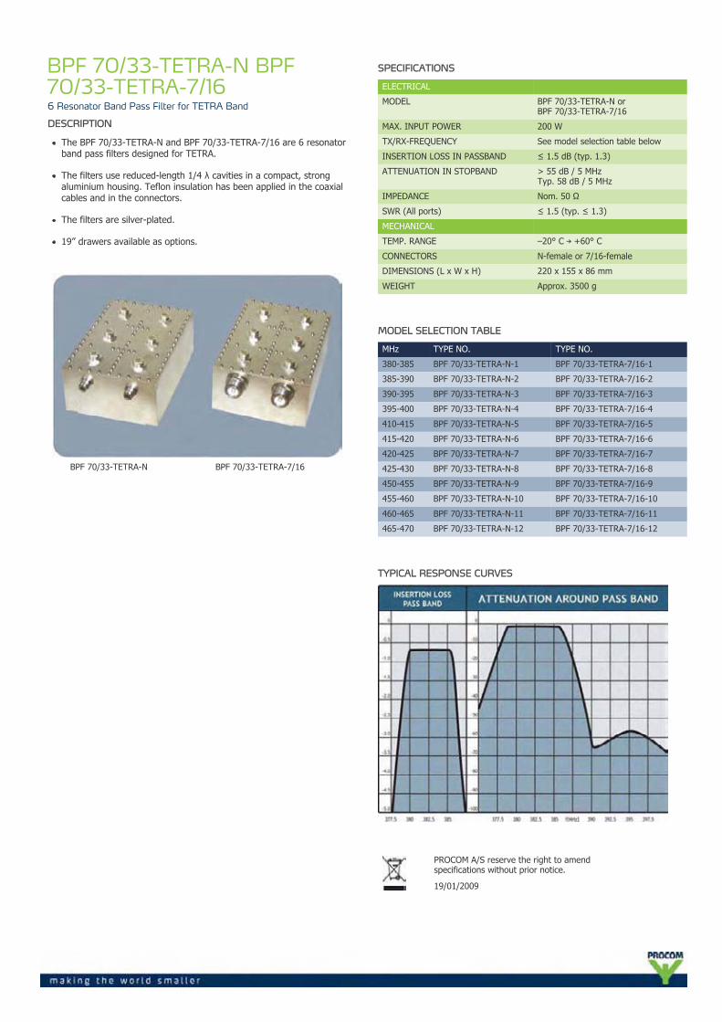
BPF 70/33-TETRA-N BPF70/33-TETRA-7/166 Resonator Band Pass Filter for TETRA Band
DESCRIPTION
The BPF 70/33-TETRA-N and BPF 70/33-TETRA-7/16 are 6 resonatorband pass filters designed for TETRA.
The filters use reduced-length 1/4 λ cavities in a compact, strongaluminium housing. Teflon insulation has been applied in the coaxialcables and in the connectors.
The filters are silver-plated.
19” drawers available as options.
BPF 70/33-TETRA-N BPF 70/33-TETRA-7/16
SPECIFICATIONS
ELECTRICAL
MODEL BPF 70/33-TETRA-N orBPF 70/33-TETRA-7/16
MAX. INPUT POWER 200 W
TX/RX-FREQUENCY See model selection table below
INSERTION LOSS IN PASSBAND ≤ 1.5 dB (typ. 1.3)
ATTENUATION IN STOPBAND > 55 dB / 5 MHzTyp. 58 dB / 5 MHz
IMPEDANCE Nom. 50 Ω
SWR (All ports) ≤ 1.5 (typ. ≤ 1.3)
MECHANICAL
TEMP. RANGE –20° C → +60° C
CONNECTORS N-female or 7/16-female
DIMENSIONS (L x W x H) 220 x 155 x 86 mm
WEIGHT Approx. 3500 g
MODEL SELECTION TABLE
MHz TYPE NO. TYPE NO.
380-385 BPF 70/33-TETRA-N-1 BPF 70/33-TETRA-7/16-1
385-390 BPF 70/33-TETRA-N-2 BPF 70/33-TETRA-7/16-2
390-395 BPF 70/33-TETRA-N-3 BPF 70/33-TETRA-7/16-3
395-400 BPF 70/33-TETRA-N-4 BPF 70/33-TETRA-7/16-4
410-415 BPF 70/33-TETRA-N-5 BPF 70/33-TETRA-7/16-5
415-420 BPF 70/33-TETRA-N-6 BPF 70/33-TETRA-7/16-6
420-425 BPF 70/33-TETRA-N-7 BPF 70/33-TETRA-7/16-7
425-430 BPF 70/33-TETRA-N-8 BPF 70/33-TETRA-7/16-8
450-455 BPF 70/33-TETRA-N-9 BPF 70/33-TETRA-7/16-9
455-460 BPF 70/33-TETRA-N-10 BPF 70/33-TETRA-7/16-10
460-465 BPF 70/33-TETRA-N-11 BPF 70/33-TETRA-7/16-11
465-470 BPF 70/33-TETRA-N-12 BPF 70/33-TETRA-7/16-12
TYPICAL RESPONSE CURVES
PROCOM A/S reserve the right to amendspecifications without prior notice.
19/01/2009
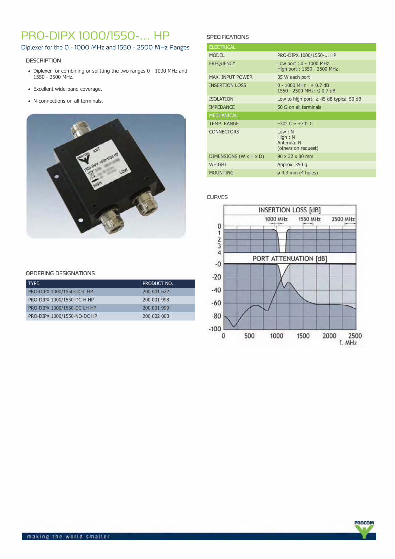
PRO-DIPX 1000/1550-... HPDiplexer for the 0 - 1000 MHz and 1550 - 2500 MHz Ranges
DESCRIPTION
Diplexer for combining or splitting the two ranges 0 - 1000 MHz and1550 - 2500 MHz.
Excellent wide-band coverage.
N-connections on all terminals.
ORDERING DESIGNATIONS
TYPE PRODUCT NO.
PRO-DIPX 1000/1550-DC-L HP 200 001 622
PRO-DIPX 1000/1550-DC-H HP 200 001 998
PRO-DIPX 1000/1550-DC-LH HP 200 001 999
PRO-DIPX 1000/1550-NO-DC HP 200 002 000
SPECIFICATIONS
ELECTRICAL
MODEL PRO-DIPX 1000/1550-... HP
FREQUENCY Low port : 0 - 1000 MHzHigh port : 1550 - 2500 MHz
MAX. INPUT POWER 35 W each port
INSERTION LOSS 0 - 1000 MHz : ≤ 0.7 dB1550 - 2500 MHz: ≤ 0.7 dB
ISOLATION Low to high port: ≥ 45 dB typical 50 dB
IMPEDANCE 50 Ω on all terminals
MECHANICAL
TEMP. RANGE –30° C → +70° C
CONNECTORS Low : NHigh : NAntenna: N(others on request)
DIMENSIONS (W x H x D) 96 x 32 x 80 mm
WEIGHT Approx. 350 g
MOUNTING ø 4.3 mm (4 holes)
CURVES
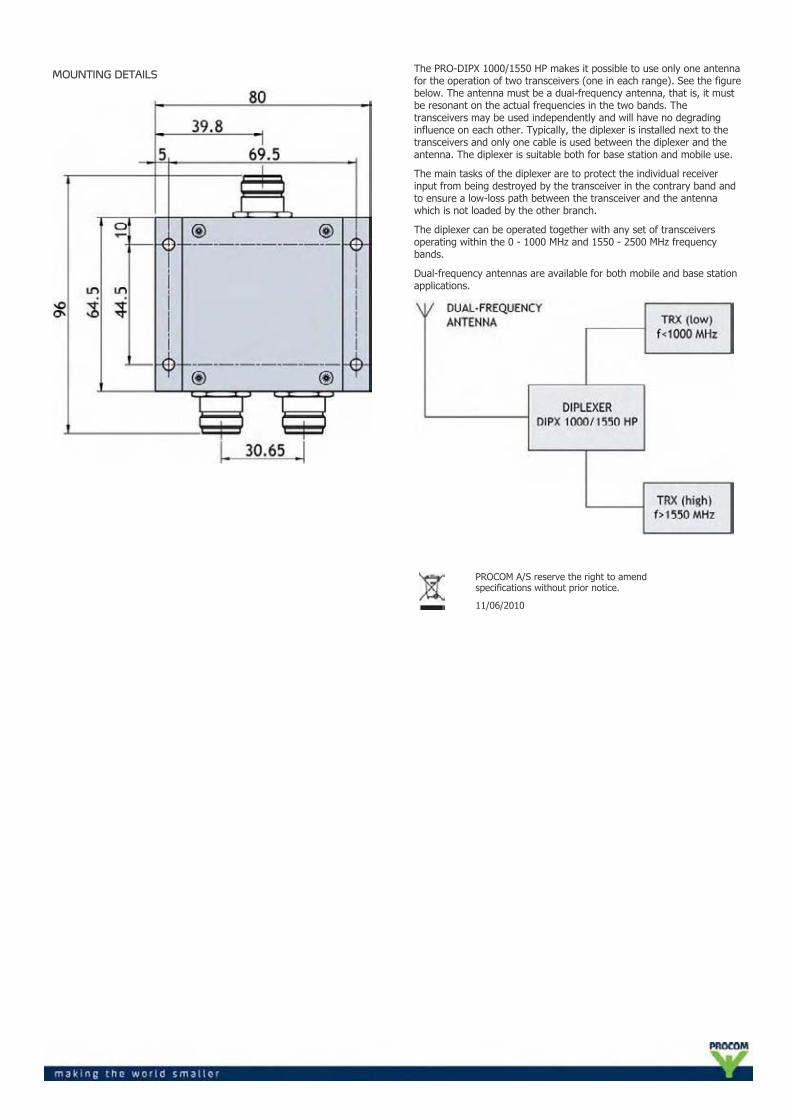
MOUNTING DETAILS
The PRO-DIPX 1000/1550 HP makes it possible to use only one antennafor the operation of two transceivers (one in each range). See the figurebelow. The antenna must be a dual-frequency antenna, that is, it mustbe resonant on the actual frequencies in the two bands. Thetransceivers may be used independently and will have no degradinginfluence on each other. Typically, the diplexer is installed next to thetransceivers and only one cable is used between the diplexer and theantenna. The diplexer is suitable both for base station and mobile use.
The main tasks of the diplexer are to protect the individual receiverinput from being destroyed by the transceiver in the contrary band andto ensure a low-loss path between the transceiver and the antennawhich is not loaded by the other branch.
The diplexer can be operated together with any set of transceiversoperating within the 0 - 1000 MHz and 1550 - 2500 MHz frequencybands.
Dual-frequency antennas are available for both mobile and base stationapplications.
PROCOM A/S reserve the right to amendspecifications without prior notice.
11/06/2010
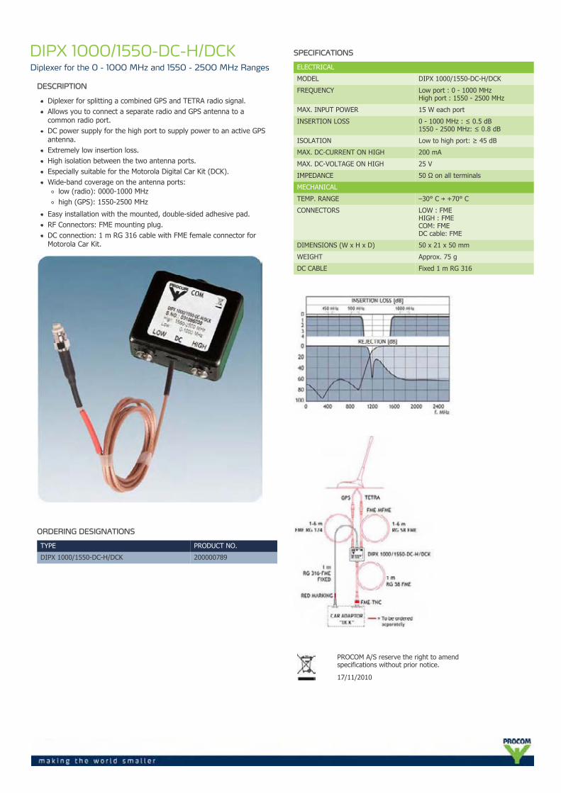
DIPX 1000/1550-DC-H/DCKDiplexer for the 0 - 1000 MHz and 1550 - 2500 MHz Ranges
DESCRIPTION
Diplexer for splitting a combined GPS and TETRA radio signal.Allows you to connect a separate radio and GPS antenna to acommon radio port.DC power supply for the high port to supply power to an active GPSantenna.Extremely low insertion loss.High isolation between the two antenna ports.Especially suitable for the Motorola Digital Car Kit (DCK).Wide-band coverage on the antenna ports:
low (radio): 0000-1000 MHzhigh (GPS): 1550-2500 MHz
Easy installation with the mounted, double-sided adhesive pad.RF Connectors: FME mounting plug.DC connection: 1 m RG 316 cable with FME female connector forMotorola Car Kit.
ORDERING DESIGNATIONS
TYPE PRODUCT NO.
DIPX 1000/1550-DC-H/DCK 200000789
SPECIFICATIONS
ELECTRICAL
MODEL DIPX 1000/1550-DC-H/DCK
FREQUENCY Low port : 0 - 1000 MHzHigh port : 1550 - 2500 MHz
MAX. INPUT POWER 15 W each port
INSERTION LOSS 0 - 1000 MHz : ≤ 0.5 dB1550 - 2500 MHz: ≤ 0.8 dB
ISOLATION Low to high port: ≥ 45 dB
MAX. DC-CURRENT ON HIGH 200 mA
MAX. DC-VOLTAGE ON HIGH 25 V
IMPEDANCE 50 Ω on all terminals
MECHANICAL
TEMP. RANGE –30° C → +70° C
CONNECTORS LOW : FMEHIGH : FMECOM: FMEDC cable: FME
DIMENSIONS (W x H x D) 50 x 21 x 50 mm
WEIGHT Approx. 75 g
DC CABLE Fixed 1 m RG 316
PROCOM A/S reserve the right to amendspecifications without prior notice.
17/11/2010
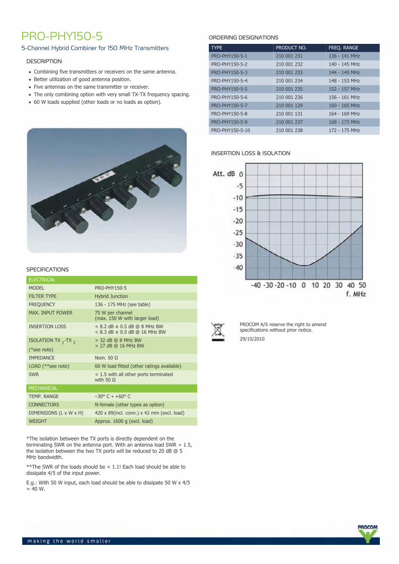
PRO-PHY150-55-Channel Hybrid Combiner for 150 MHz Transmitters
DESCRIPTION
Combining five transmitters or receivers on the same antenna.Better utilization of good antenna position.Five antennas on the same transmitter or receiver.The only combining option with very small TX-TX frequency spacing.60 W loads supplied (other loads or no loads as option).
SPECIFICATIONS
ELECTRICAL
MODEL PRO-PHY150-5
FILTER TYPE Hybrid Junction
FREQUENCY 136 - 175 MHz (see table)
MAX. INPUT POWER 75 W per channel(max. 150 W with larger load)
INSERTION LOSS < 8.2 dB ± 0.5 dB @ 8 MHz BW< 8.3 dB ± 0.5 dB @ 16 MHz BW
ISOLATION TX 1-TX 2(*see note)
> 32 dB @ 8 MHz BW> 27 dB @ 16 MHz BW
IMPEDANCE Nom. 50 Ω
LOAD (**see note) 60 W load fitted (other ratings available)
SWR < 1.5 with all other ports terminatedwith 50 Ω
MECHANICAL
TEMP. RANGE –30° C → +60° C
CONNECTORS N-female (other types as option)
DIMENSIONS (L x W x H) 420 x 89(incl. conn.) x 42 mm (excl. load)
WEIGHT Approx. 1600 g (excl. load)
*The isolation between the TX ports is directly dependent on theterminating SWR on the antenna port. With an antenna load SWR = 1.5,the isolation between the two TX ports will be reduced to 20 dB @ 5MHz bandwidth.
**The SWR of the loads should be < 1.1! Each load should be able todissipate 4/5 of the input power.
E.g.: With 50 W input, each load should be able to dissipate 50 W x 4/5= 40 W.
ORDERING DESIGNATIONS
TYPE PRODUCT NO. FREQ. RANGE
PRO-PHY150-5-1 210 001 231 136 - 141 MHz
PRO-PHY150-5-2 210 001 232 140 - 145 MHz
PRO-PHY150-5-3 210 001 233 144 - 149 MHz
PRO-PHY150-5-4 210 001 234 148 - 153 MHz
PRO-PHY150-5-5 210 001 235 152 - 157 MHz
PRO-PHY150-5-6 210 001 236 156 - 161 MHz
PRO-PHY150-5-7 210 001 129 160 - 165 MHz
PRO-PHY150-5-8 210 001 131 164 - 169 MHz
PRO-PHY150-5-9 210 001 237 168 - 173 MHz
PRO-PHY150-5-10 210 001 238 172 - 175 MHz
INSERTION LOSS & ISOLATION
PROCOM A/S reserve the right to amendspecifications without prior notice.
29/10/2010
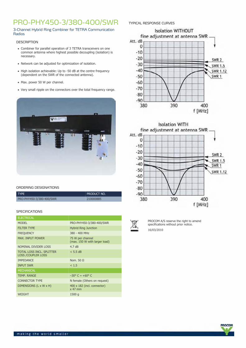
PRO-PHY450-3/380-400/SWR3-Channel Hybrid Ring Combiner for TETRA CommunicationRadios
DESCRIPTION
Combiner for parallel operation of 3 TETRA transceivers on onecommon antenna where highest possible decoupling (isolation) isnecessary.
Network can be adjusted for optimization of isolation.
High isolation achievable: Up to -50 dB at the centre frequency(dependent on the SWR of the connected antenna).
Max. power 50 W per channel.
Very small ripple on the connectors over the total frequency range.
ORDERING DESIGNATIONS
TYPE PRODUCT NO.
PRO-PHY450-3/380-400/SWR 210000885
SPECIFICATIONS
ELECTRICAL
MODEL PRO-PHY450-3/380-400/SWR
FILTER TYPE Hybrid Ring Junction
FREQUENCY 380 - 400 MHz
MAX. INPUT POWER 75 W per channel(max. 150 W with larger load)
NOMINAL DIVIDER LOSS 4.7 dB
TOTAL LOSS INCL. SPLITTERLOSS /COUPLER LOSS
< 5.5 dB
IMPEDANCE Nom. 50 Ω
INPUT SWR < 1.5
MECHANICAL
TEMP. RANGE –30° C → +60° C
CONNECTOR TYPE N female (Others on request)
DIMENSIONS (L x W x H) 400 x 182 (incl. connector)x 47 mm
WEIGHT 1500 g
TYPICAL RESPONSE CURVES
PROCOM A/S reserve the right to amendspecifications without prior notice.
16/03/2010
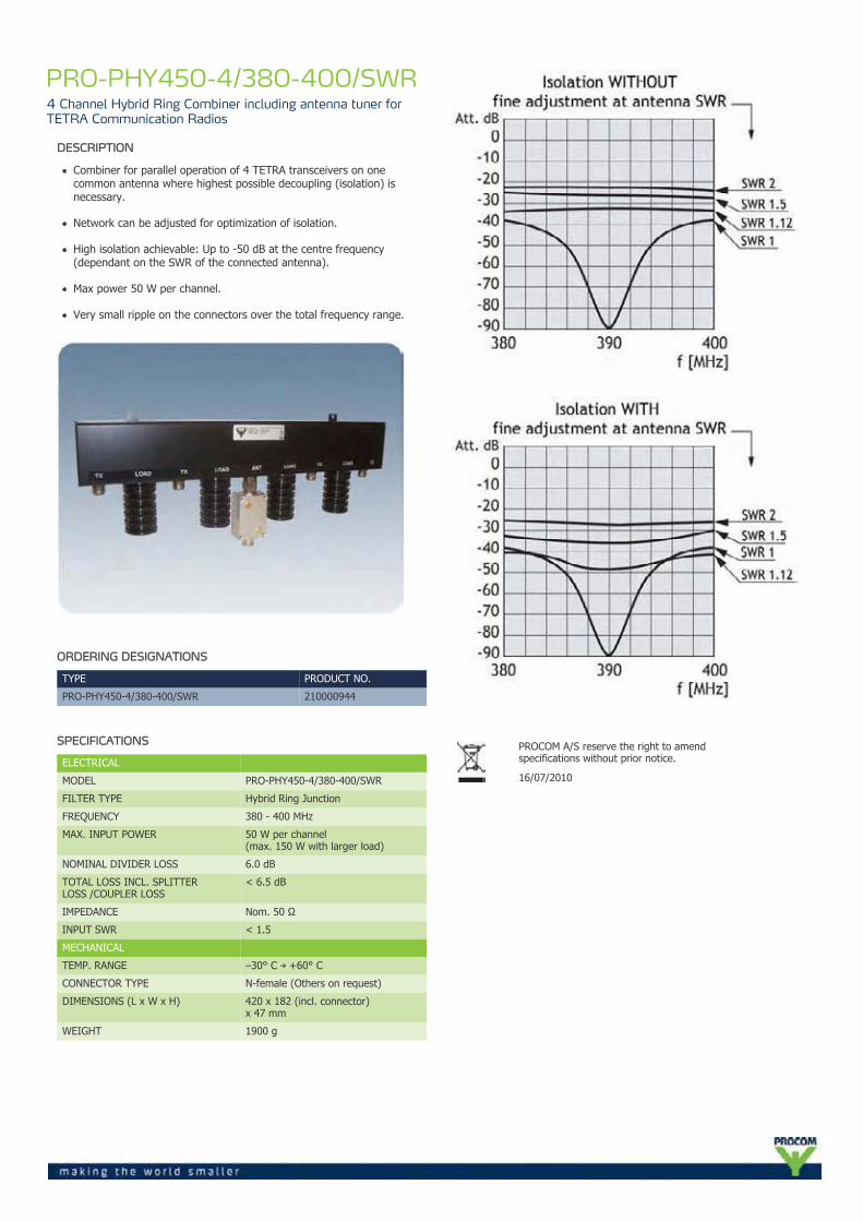
PRO-PHY450-4/380-400/SWR4 Channel Hybrid Ring Combiner including antenna tuner forTETRA Communication Radios
DESCRIPTION
Combiner for parallel operation of 4 TETRA transceivers on onecommon antenna where highest possible decoupling (isolation) isnecessary.
Network can be adjusted for optimization of isolation.
High isolation achievable: Up to -50 dB at the centre frequency(dependant on the SWR of the connected antenna).
Max power 50 W per channel.
Very small ripple on the connectors over the total frequency range.
ORDERING DESIGNATIONS
TYPE PRODUCT NO.
PRO-PHY450-4/380-400/SWR 210000944
SPECIFICATIONS
ELECTRICAL
MODEL PRO-PHY450-4/380-400/SWR
FILTER TYPE Hybrid Ring Junction
FREQUENCY 380 - 400 MHz
MAX. INPUT POWER 50 W per channel(max. 150 W with larger load)
NOMINAL DIVIDER LOSS 6.0 dB
TOTAL LOSS INCL. SPLITTERLOSS /COUPLER LOSS
< 6.5 dB
IMPEDANCE Nom. 50 Ω
INPUT SWR < 1.5
MECHANICAL
TEMP. RANGE –30° C → +60° C
CONNECTOR TYPE N-female (Others on request)
DIMENSIONS (L x W x H) 420 x 182 (incl. connector)x 47 mm
WEIGHT 1900 g
PROCOM A/S reserve the right to amendspecifications without prior notice.
16/07/2010

PRO-DIR 112-200-10 dBDirectional Coupler 100 W
DESCRIPTION
100 W Directional Coupler with 10 dB coupling covering the112 - 200 MHz band.
Excellent high power performance.
Very low VSWR and insertion loss over the entire frequency range.
ORDERING DESIGNATIONS
TYPE PRODUCT NO.
PRO-DIR 112-200-10 dB 210001031
SPECIFICATIONS
ELECTRICAL
MODEL PRO-DIR 112-200-10 dB
FREQUENCY RANGE 112 - 200 MHz
COUPLING 10 dB
MAX. INPUT POWER 100 W
NOMINAL DIVIDER LOSS 0.1 dB
TOTAL LOSS INCL. NOMINAL LOSS <0.7 dB
IMPEDANCE Nom. 50 Ω
INPUT SWR ≤1.2
COMPLIANCE RoHS, IP66
MECHANICAL
TEMP. RANGE -30° C → +60° C
CONNECTORS N-female
DIMENSIONS (L x W x H) 165 x 75 x 35 mm
WEIGHT Approx. 375 g
MOUNTING M4 mm (4 holes)
MOUNTING DETAILS
PROCOM A/S reserve the right to amendspecifications without prior notice.
19/03/2010
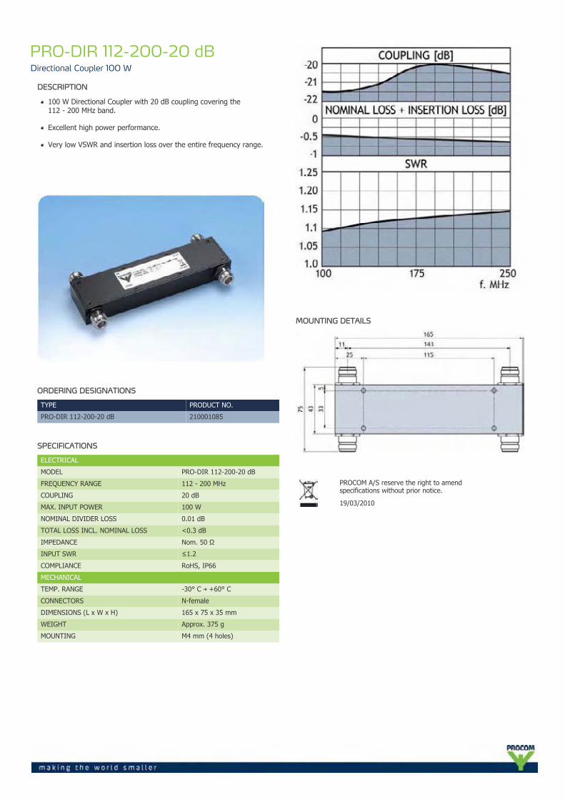
PRO-DIR 112-200-20 dBDirectional Coupler 100 W
DESCRIPTION
100 W Directional Coupler with 20 dB coupling covering the112 - 200 MHz band.
Excellent high power performance.
Very low VSWR and insertion loss over the entire frequency range.
ORDERING DESIGNATIONS
TYPE PRODUCT NO.
PRO-DIR 112-200-20 dB 210001085
SPECIFICATIONS
ELECTRICAL
MODEL PRO-DIR 112-200-20 dB
FREQUENCY RANGE 112 - 200 MHz
COUPLING 20 dB
MAX. INPUT POWER 100 W
NOMINAL DIVIDER LOSS 0.01 dB
TOTAL LOSS INCL. NOMINAL LOSS <0.3 dB
IMPEDANCE Nom. 50 Ω
INPUT SWR ≤1.2
COMPLIANCE RoHS, IP66
MECHANICAL
TEMP. RANGE -30° C → +60° C
CONNECTORS N-female
DIMENSIONS (L x W x H) 165 x 75 x 35 mm
WEIGHT Approx. 375 g
MOUNTING M4 mm (4 holes)
MOUNTING DETAILS
PROCOM A/S reserve the right to amendspecifications without prior notice.
19/03/2010
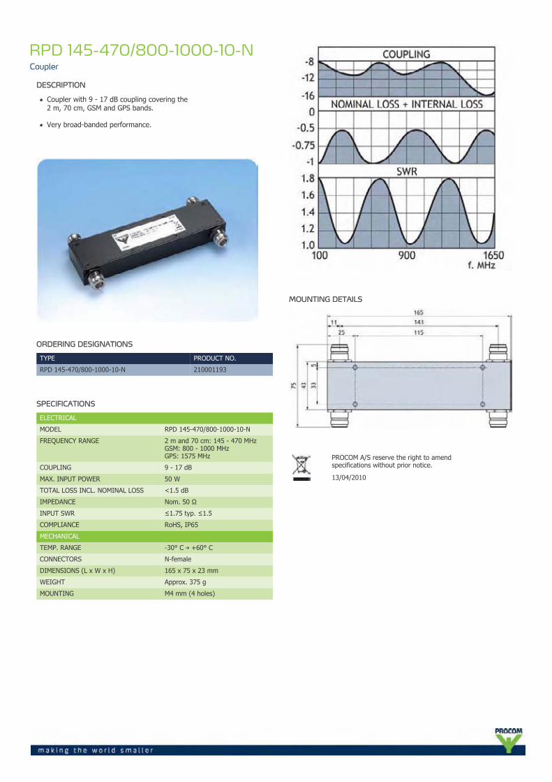
RPD 145-470/800-1000-10-NCoupler
DESCRIPTION
Coupler with 9 - 17 dB coupling covering the2 m, 70 cm, GSM and GPS bands.
Very broad-banded performance.
ORDERING DESIGNATIONS
TYPE PRODUCT NO.
RPD 145-470/800-1000-10-N 210001193
SPECIFICATIONS
ELECTRICAL
MODEL RPD 145-470/800-1000-10-N
FREQUENCY RANGE 2 m and 70 cm: 145 - 470 MHzGSM: 800 - 1000 MHzGPS: 1575 MHz
COUPLING 9 - 17 dB
MAX. INPUT POWER 50 W
TOTAL LOSS INCL. NOMINAL LOSS <1.5 dB
IMPEDANCE Nom. 50 Ω
INPUT SWR ≤1.75 typ. ≤1.5
COMPLIANCE RoHS, IP65
MECHANICAL
TEMP. RANGE -30° C → +60° C
CONNECTORS N-female
DIMENSIONS (L x W x H) 165 x 75 x 23 mm
WEIGHT Approx. 375 g
MOUNTING M4 mm (4 holes)
MOUNTING DETAILS
PROCOM A/S reserve the right to amendspecifications without prior notice.
13/04/2010
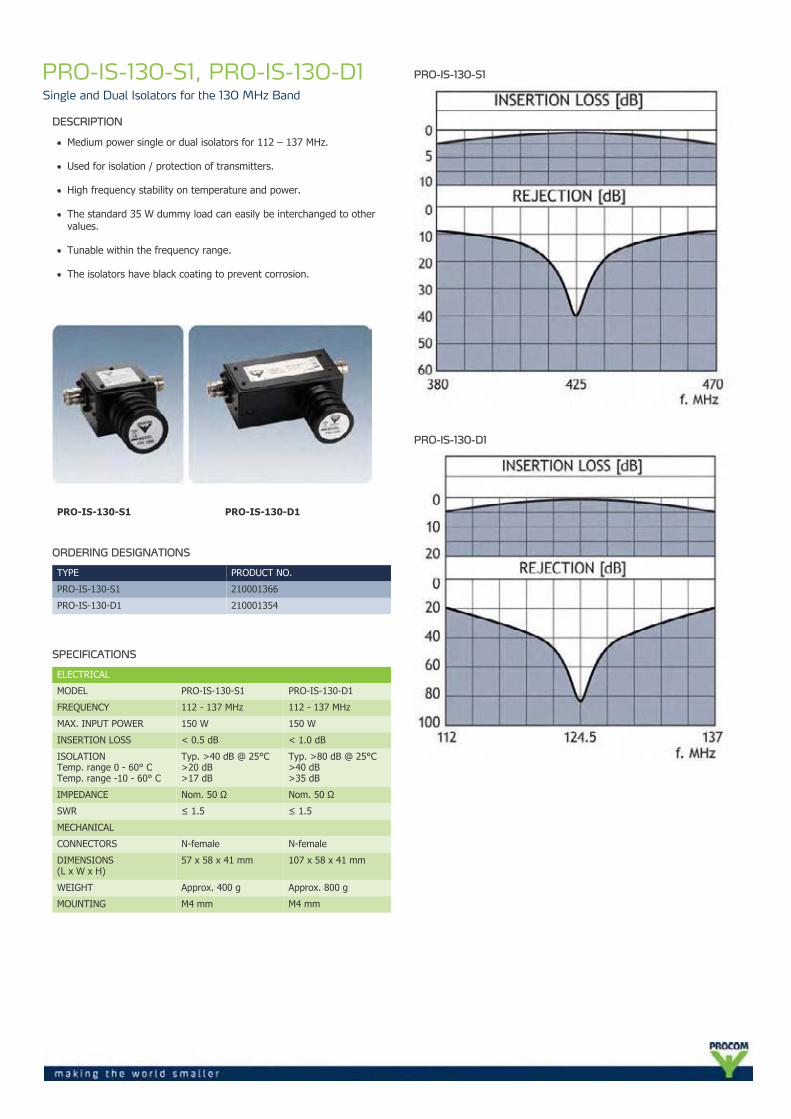
PRO-IS-130-S1, PRO-IS-130-D1Single and Dual Isolators for the 130 MHz Band
DESCRIPTION
Medium power single or dual isolators for 112 – 137 MHz.
Used for isolation / protection of transmitters.
High frequency stability on temperature and power.
The standard 35 W dummy load can easily be interchanged to othervalues.
Tunable within the frequency range.
The isolators have black coating to prevent corrosion.
PRO-IS-130-S1 PRO-IS-130-D1
ORDERING DESIGNATIONS
TYPE PRODUCT NO.
PRO-IS-130-S1 210001366
PRO-IS-130-D1 210001354
SPECIFICATIONS
ELECTRICAL
MODEL PRO-IS-130-S1 PRO-IS-130-D1
FREQUENCY 112 - 137 MHz 112 - 137 MHz
MAX. INPUT POWER 150 W 150 W
INSERTION LOSS < 0.5 dB < 1.0 dB
ISOLATIONTemp. range 0 - 60° CTemp. range -10 - 60° C
Typ. >40 dB @ 25°C>20 dB>17 dB
Typ. >80 dB @ 25°C>40 dB>35 dB
IMPEDANCE Nom. 50 Ω Nom. 50 Ω
SWR ≤ 1.5 ≤ 1.5
MECHANICAL
CONNECTORS N-female N-female
DIMENSIONS(L x W x H)
57 x 58 x 41 mm 107 x 58 x 41 mm
WEIGHT Approx. 400 g Approx. 800 g
MOUNTING M4 mm M4 mm
PRO-IS-130-S1
PRO-IS-130-D1
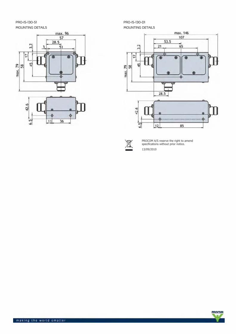
PRO-IS-130-S1
MOUNTING DETAILS
PRO-IS-130-D1
MOUNTING DETAILS
PROCOM A/S reserve the right to amendspecifications without prior notice.
13/09/2010
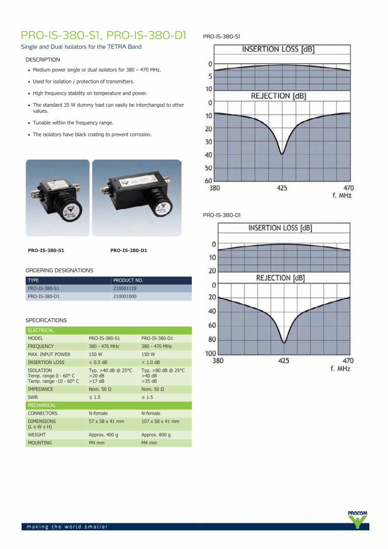
PRO-IS-380-S1, PRO-IS-380-D1Single and Dual Isolators for the TETRA Band
DESCRIPTION
Medium power single or dual isolators for 380 – 470 MHz.
Used for isolation / protection of transmitters.
High frequency stability on temperature and power.
The standard 35 W dummy load can easily be interchanged to othervalues.
Tunable within the frequency range.
The isolators have black coating to prevent corrosion.
PRO-IS-380-S1 PRO-IS-380-D1
ORDERING DESIGNATIONS
TYPE PRODUCT NO.
PRO-IS-380-S1 210001119
PRO-IS-380-D1 210001000
SPECIFICATIONS
ELECTRICAL
MODEL PRO-IS-380-S1 PRO-IS-380-D1
FREQUENCY 380 - 470 MHz 380 - 470 MHz
MAX. INPUT POWER 150 W 150 W
INSERTION LOSS < 0.5 dB < 1.0 dB
ISOLATIONTemp. range 0 - 60° CTemp. range -10 - 60° C
Typ. >40 dB @ 25°C>20 dB>17 dB
Typ. >80 dB @ 25°C>40 dB>35 dB
IMPEDANCE Nom. 50 Ω Nom. 50 Ω
SWR ≤ 1.5 ≤ 1.5
MECHANICAL
CONNECTORS N-female N-female
DIMENSIONS(L x W x H)
57 x 58 x 41 mm 107 x 58 x 41 mm
WEIGHT Approx. 400 g Approx. 800 g
MOUNTING M4 mm M4 mm
PRO-IS-380-S1
PRO-IS-380-D1
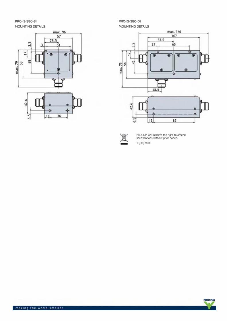
PRO-IS-380-S1
MOUNTING DETAILS
PRO-IS-380-D1
MOUNTING DETAILS
PROCOM A/S reserve the right to amendspecifications without prior notice.
13/09/2010
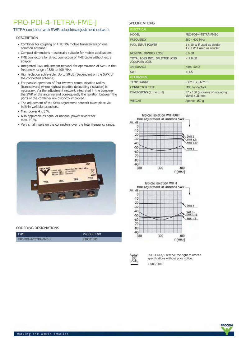
PRO-PDI-4-TETRA-FME-JTETRA combiner with SWR adaption/adjustment network
DESCRIPTION
Combiner for coupling of 4 TETRA mobile transceivers on onecommon antenna.Compact dimensions – especially suitable for mobile applications.FME connectors for direct connection of FME cable without extraadapter.Integrated SWR adjustment network for optimization of SWR in thefrequency range of 380 to 400 MHz.High isolation achievable: Up to 50 dB (Dependant on the SWR ofthe connected antenna)For parallel operation of four twoway communication radios(transceivers) where highest possible decoupling (isolation) isnecessary. Via the adjustment network integrated in the combinerthe SWR of the antenna and consequently the isolation between theports of the combiner are distinctly improved.The adjustment of the SWR adjustment network takes place viabuilt-in variable capacitors.Max. power 4 x 3 W.Also applicable as equal or unequal power divider formax. 10 W.Very small ripple on the connectors over the total frequency range.
ORDERING DESIGNATIONS
TYPE PRODUCT NO.
PRO-PDI-4-TETRA-FME-J 210001005
SPECIFICATIONS
ELECTRICAL
MODEL PRO-PDI-4-TETRA-FME-J
FREQUENCY 380 - 400 MHz
MAX. INPUT POWER 1 x 10 W if used as divider4 x 3 W if used as coupler
NOMINAL DIVIDER LOSS 6.0 dB
TOTAL LOSS INCL. SPLITTER LOSS/COUPLER LOSS
< 7.0 dB
IMPEDANCE Nom. 50 Ω
SWR < 1.5
MECHANICAL
TEMP. RANGE –30° C → +60° C
CONNECTOR TYPE FME connectors
DIMENSIONS (L x W x H) 57 x 100 (inclusive of mountingplate) x 28 mm
WEIGHT Approx. 150 g
PROCOM A/S reserve the right to amendspecifications without prior notice.
17/03/2010
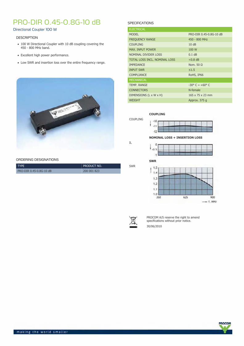
PRO-DIR 0.45-0.8G-10 dBDirectional Coupler 100 W
DESCRIPTION
100 W Directional Coupler with 10 dB coupling covering the450 - 800 MHz band.
Excellent high power performance.
Low SWR and insertion loss over the entire frequency range.
ORDERING DESIGNATIONS
TYPE PRODUCT NO.
PRO-DIR 0.45-0.8G-10 dB 200 001 823
SPECIFICATIONS
ELECTRICAL
MODEL PRO-DIR 0.45-0.8G-10 dB
FREQUENCY RANGE 450 - 800 MHz
COUPLING 10 dB
MAX. INPUT POWER 100 W
NOMINAL DIVIDER LOSS 0.1 dB
TOTAL LOSS INCL. NOMINAL LOSS <0.8 dB
IMPEDANCE Nom. 50 Ω
INPUT SWR ≤1.5
COMPLIANCE RoHS, IP66
MECHANICAL
TEMP. RANGE -30° C → +60° C
CONNECTORS N-female
DIMENSIONS (L x W x H) 165 x 75 x 23 mm
WEIGHT Approx. 375 g
COUPLING
COUPLING
NOMINAL LOSS + INSERTION LOSS
IL
SWR
SWR
PROCOM A/S reserve the right to amendspecifications without prior notice.
30/06/2010
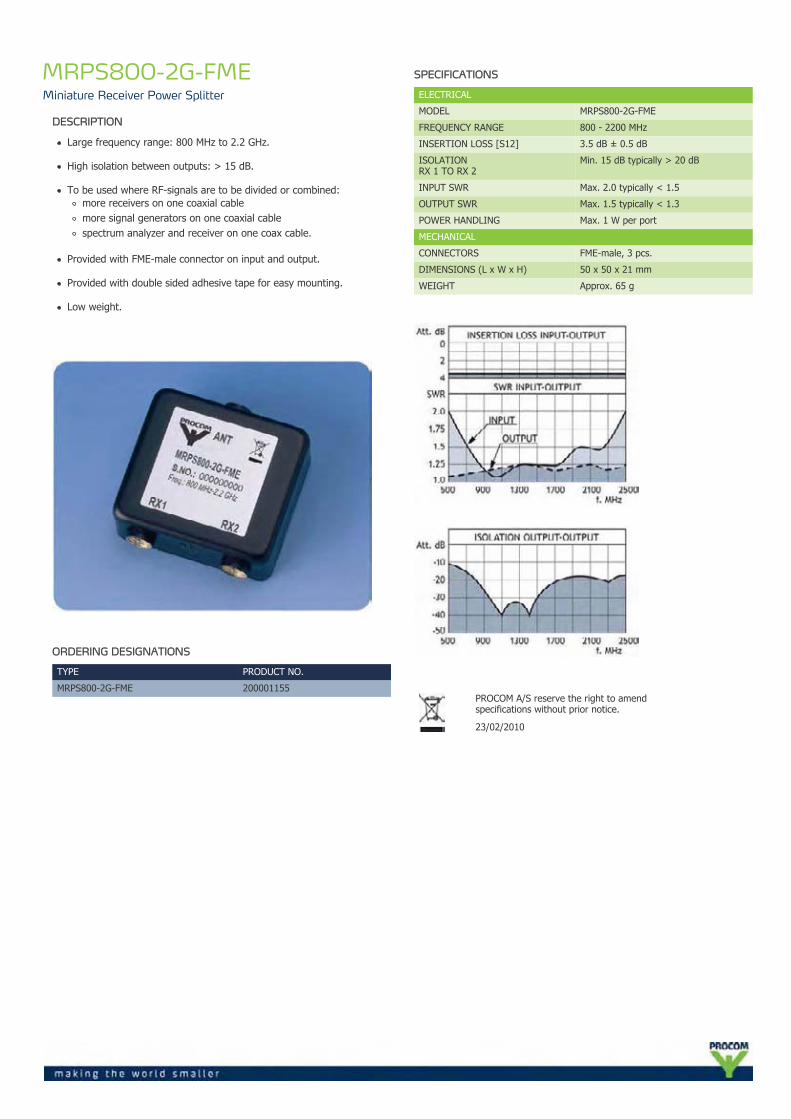
MRPS800-2G-FMEMiniature Receiver Power Splitter
DESCRIPTION
Large frequency range: 800 MHz to 2.2 GHz.
High isolation between outputs: > 15 dB.
To be used where RF-signals are to be divided or combined:more receivers on one coaxial cablemore signal generators on one coaxial cablespectrum analyzer and receiver on one coax cable.
Provided with FME-male connector on input and output.
Provided with double sided adhesive tape for easy mounting.
Low weight.
ORDERING DESIGNATIONS
TYPE PRODUCT NO.
MRPS800-2G-FME 200001155
SPECIFICATIONS
ELECTRICAL
MODEL MRPS800-2G-FME
FREQUENCY RANGE 800 - 2200 MHz
INSERTION LOSS [S12] 3.5 dB ± 0.5 dB
ISOLATIONRX 1 TO RX 2
Min. 15 dB typically > 20 dB
INPUT SWR Max. 2.0 typically < 1.5
OUTPUT SWR Max. 1.5 typically < 1.3
POWER HANDLING Max. 1 W per port
MECHANICAL
CONNECTORS FME-male, 3 pcs.
DIMENSIONS (L x W x H) 50 x 50 x 21 mm
WEIGHT Approx. 65 g
PROCOM A/S reserve the right to amendspecifications without prior notice.
23/02/2010
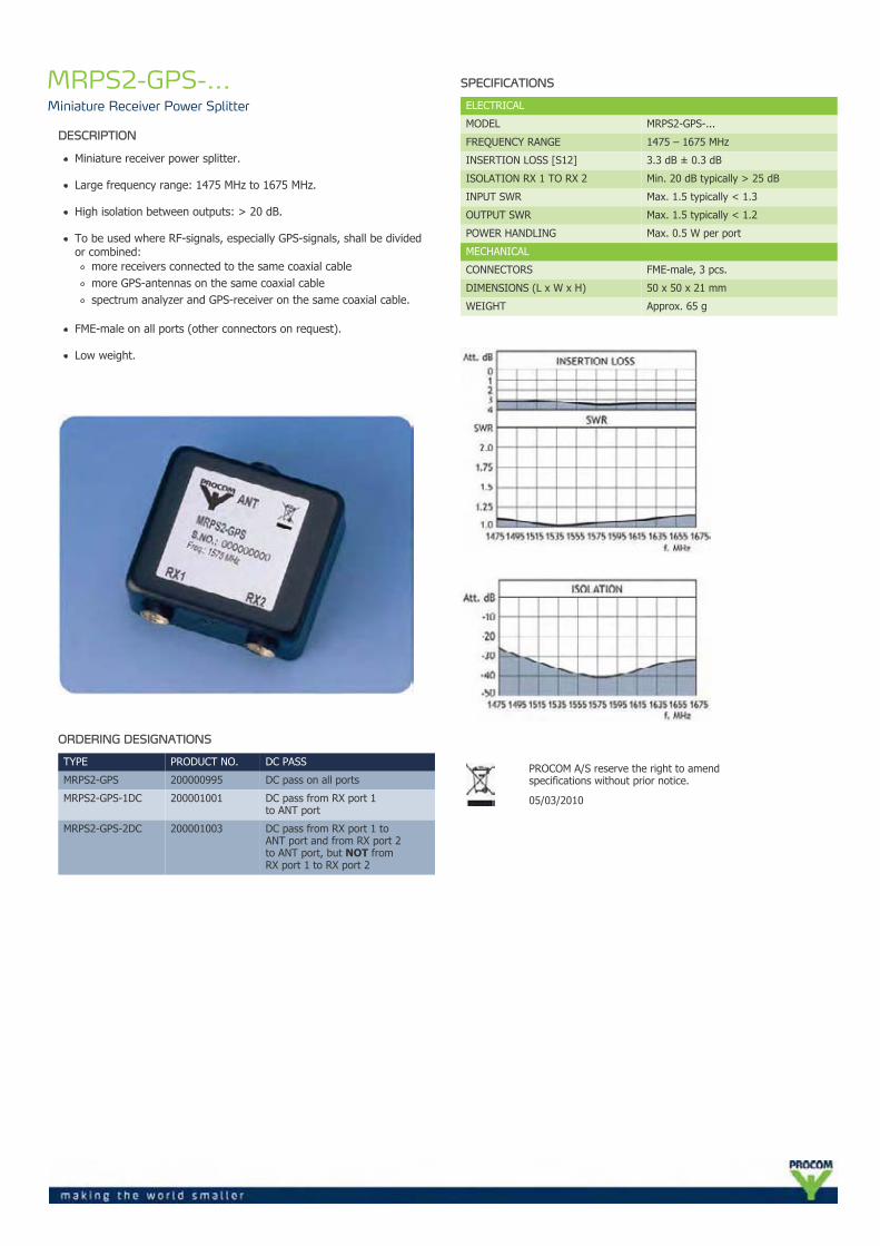
MRPS2-GPS-...Miniature Receiver Power Splitter
DESCRIPTION
Miniature receiver power splitter.
Large frequency range: 1475 MHz to 1675 MHz.
High isolation between outputs: > 20 dB.
To be used where RF-signals, especially GPS-signals, shall be dividedor combined:
more receivers connected to the same coaxial cablemore GPS-antennas on the same coaxial cablespectrum analyzer and GPS-receiver on the same coaxial cable.
FME-male on all ports (other connectors on request).
Low weight.
ORDERING DESIGNATIONS
TYPE PRODUCT NO. DC PASS
MRPS2-GPS 200000995 DC pass on all ports
MRPS2-GPS-1DC 200001001 DC pass from RX port 1to ANT port
MRPS2-GPS-2DC 200001003 DC pass from RX port 1 toANT port and from RX port 2to ANT port, but NOT fromRX port 1 to RX port 2
SPECIFICATIONS
ELECTRICAL
MODEL MRPS2-GPS-...
FREQUENCY RANGE 1475 – 1675 MHz
INSERTION LOSS [S12] 3.3 dB ± 0.3 dB
ISOLATION RX 1 TO RX 2 Min. 20 dB typically > 25 dB
INPUT SWR Max. 1.5 typically < 1.3
OUTPUT SWR Max. 1.5 typically < 1.2
POWER HANDLING Max. 0.5 W per port
MECHANICAL
CONNECTORS FME-male, 3 pcs.
DIMENSIONS (L x W x H) 50 x 50 x 21 mm
WEIGHT Approx. 65 g
PROCOM A/S reserve the right to amendspecifications without prior notice.
05/03/2010
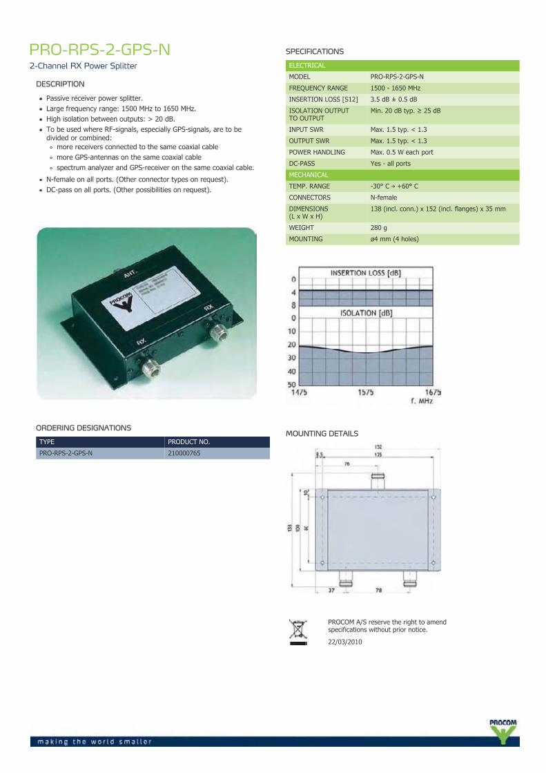
PRO-RPS-2-GPS-N2-Channel RX Power Splitter
DESCRIPTION
Passive receiver power splitter.Large frequency range: 1500 MHz to 1650 MHz.High isolation between outputs: > 20 dB.To be used where RF-signals, especially GPS-signals, are to bedivided or combined:
more receivers connected to the same coaxial cablemore GPS-antennas on the same coaxial cablespectrum analyzer and GPS-receiver on the same coaxial cable.
N-female on all ports. (Other connector types on request).DC-pass on all ports. (Other possibilities on request).
ORDERING DESIGNATIONS
TYPE PRODUCT NO.
PRO-RPS-2-GPS-N 210000765
SPECIFICATIONS
ELECTRICAL
MODEL PRO-RPS-2-GPS-N
FREQUENCY RANGE 1500 - 1650 MHz
INSERTION LOSS [S12] 3.5 dB ± 0.5 dB
ISOLATION OUTPUTTO OUTPUT
Min. 20 dB typ. ≥ 25 dB
INPUT SWR Max. 1.5 typ. < 1.3
OUTPUT SWR Max. 1.5 typ. < 1.3
POWER HANDLING Max. 0.5 W each port
DC-PASS Yes - all ports
MECHANICAL
TEMP. RANGE -30° C → +60° C
CONNECTORS N-female
DIMENSIONS(L x W x H)
138 (incl. conn.) x 152 (incl. flanges) x 35 mm
WEIGHT 280 g
MOUNTING ø4 mm (4 holes)
MOUNTING DETAILS
PROCOM A/S reserve the right to amendspecifications without prior notice.
22/03/2010
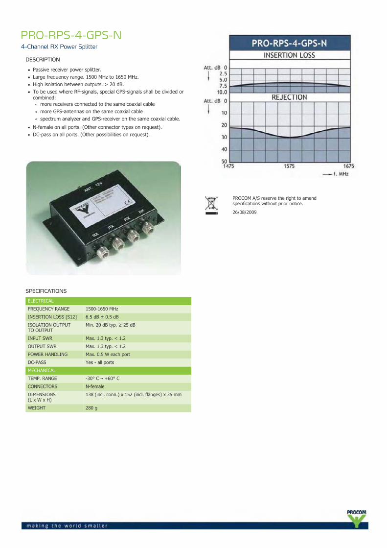
PRO-RPS-4-GPS-N4-Channel RX Power Splitter
DESCRIPTION
Passive receiver power splitter.Large frequency range. 1500 MHz to 1650 MHz.High isolation between outputs. > 20 dB.To be used where RF-signals, special GPS-signals shall be divided orcombined:
more receivers connected to the same coaxial cablemore GPS-antennas on the same coaxial cablespectrum analyzer and GPS-receiver on the same coaxial cable.
N-female on all ports. (Other connector types on request).DC-pass on all ports. (Other possibilities on request).
SPECIFICATIONS
ELECTRICAL
FREQUENCY RANGE 1500-1650 MHz
INSERTION LOSS [S12] 6.5 dB ± 0.5 dB
ISOLATION OUTPUTTO OUTPUT
Min. 20 dB typ. ≥ 25 dB
INPUT SWR Max. 1.3 typ. < 1.2
OUTPUT SWR Max. 1.3 typ. < 1.2
POWER HANDLING Max. 0.5 W each port
DC-PASS Yes - all ports
MECHANICAL
TEMP. RANGE -30° C → +60° C
CONNECTORS N-female
DIMENSIONS(L x W x H)
138 (incl. conn.) x 152 (incl. flanges) x 35 mm
WEIGHT 280 g
PROCOM A/S reserve the right to amendspecifications without prior notice.
26/08/2009
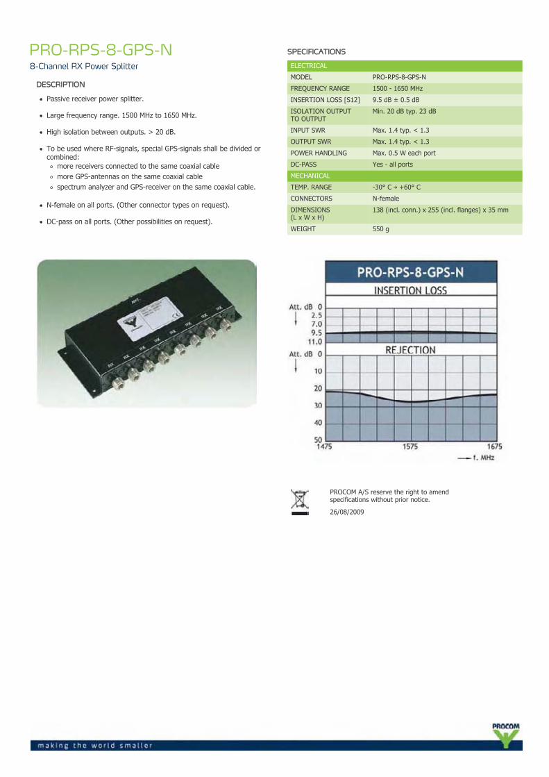
PRO-RPS-8-GPS-N8-Channel RX Power Splitter
DESCRIPTION
Passive receiver power splitter.
Large frequency range. 1500 MHz to 1650 MHz.
High isolation between outputs. > 20 dB.
To be used where RF-signals, special GPS-signals shall be divided orcombined:
more receivers connected to the same coaxial cablemore GPS-antennas on the same coaxial cablespectrum analyzer and GPS-receiver on the same coaxial cable.
N-female on all ports. (Other connector types on request).
DC-pass on all ports. (Other possibilities on request).
SPECIFICATIONS
ELECTRICAL
MODEL PRO-RPS-8-GPS-N
FREQUENCY RANGE 1500 - 1650 MHz
INSERTION LOSS [S12] 9.5 dB ± 0.5 dB
ISOLATION OUTPUTTO OUTPUT
Min. 20 dB typ. 23 dB
INPUT SWR Max. 1.4 typ. < 1.3
OUTPUT SWR Max. 1.4 typ. < 1.3
POWER HANDLING Max. 0.5 W each port
DC-PASS Yes - all ports
MECHANICAL
TEMP. RANGE -30° C → +60° C
CONNECTORS N-female
DIMENSIONS(L x W x H)
138 (incl. conn.) x 255 (incl. flanges) x 35 mm
WEIGHT 550 g
PROCOM A/S reserve the right to amendspecifications without prior notice.
26/08/2009