Embed Size (px)
Citation preview


ProCurve Series 1800 Switch
Management and Configuration Guide

© Copyright 2006 Hewlett-Packard Development Company, L.P.
The information contained herein is subject to change without notice. The only warranties for HP products and services are set forth in the express warranty statements accompanying such products and services. Nothing herein should be construed as constituting an additional warranty. HP shall not be liable for technical or editorial errors or omissions contained herein.
Windows NT®, Windows®, and MS Windows® are US registered trademarks of Microsoft Corporation.
Publication Number
5991-4726October 2006
Applicable Products
ProCurve Switch 1800-8G (J9029A)ProCurve Switch 1800-24G (J9028A)
Disclaimer
HEWLETT-PACKARD COMPANY MAKES NO WARRANTY OF ANY KIND WITH REGARD TO THIS MATERIAL, INCLUDING, BUT NOT LIMITED TO, THE IMPLIED WARRANTIES OF MERCHANTABILITY AND FITNESS FOR A PARTICULAR PURPOSE. Hewlett-Packard shall not be liable for errors contained herein or for incidental or consequential damages in connection with the furnishing, performance, or use of this material.
The only warranties for HP products and services are set forth in the express warranty statements accompanying such products and services. Nothing herein should be construed as constituting an additional warranty. HP shall not be liable for technical or editorial errors or omissions contained herein.
Hewlett-Packard assumes no responsibility for the use or reliability of its software on equipment that is not furnished by Hewlett-Packard.
Warranty
See the Customer Support/Warranty booklet included with the product. A copy of the specific warranty terms applicable to your Hewlett Packard products and replacement parts can be obtained from your HP Sales and Service Office or authorized dealer.

Contents
1 Getting Started
Introduction . . . . . . . . . . . . . . . . . . . . . . . . . . . . . . . . . . . . . . . . . . . . . . . . . . 1-1
Related Publications . . . . . . . . . . . . . . . . . . . . . . . . . . . . . . . . . . . . . . . . . . 1-1
Getting Documentation From the Web . . . . . . . . . . . . . . . . . . . . . . . . . . 1-2
Sources for More Information . . . . . . . . . . . . . . . . . . . . . . . . . . . . . . . . . 1-3
To Set Up and Install the Switch in Your Network . . . . . . . . . . . . . . . . 1-3
2 Using the ProCurve Web Browser Interface
Overview . . . . . . . . . . . . . . . . . . . . . . . . . . . . . . . . . . . . . . . . . . . . . . . . . . . . . 2-1
Navigating the Web Browser Interface . . . . . . . . . . . . . . . . . . . . . . . . . 2-1
Home Page . . . . . . . . . . . . . . . . . . . . . . . . . . . . . . . . . . . . . . . . . . . . . . . . . 2-1
Configuration Options . . . . . . . . . . . . . . . . . . . . . . . . . . . . . . . . . . . . . . . 2-2
Panel Display . . . . . . . . . . . . . . . . . . . . . . . . . . . . . . . . . . . . . . . . . . . . . . . 2-3
Main Menu . . . . . . . . . . . . . . . . . . . . . . . . . . . . . . . . . . . . . . . . . . . . . . . . . 2-3
Web Configuration . . . . . . . . . . . . . . . . . . . . . . . . . . . . . . . . . . . . . . . . . . . . 2-5
Displaying System Information . . . . . . . . . . . . . . . . . . . . . . . . . . . . . . . . 2-5
Displaying the System Name . . . . . . . . . . . . . . . . . . . . . . . . . . . . . . . . . . 2-8
Setting the Switch’s IP Address . . . . . . . . . . . . . . . . . . . . . . . . . . . . . . . . 2-8
Configuring the Logon Password . . . . . . . . . . . . . . . . . . . . . . . . . . . . . . 2-9
Rate Limits . . . . . . . . . . . . . . . . . . . . . . . . . . . . . . . . . . . . . . . . . . . . . . . . 2-10
Port Configuration . . . . . . . . . . . . . . . . . . . . . . . . . . . . . . . . . . . . . . . . . 2-12
Port Mirroring . . . . . . . . . . . . . . . . . . . . . . . . . . . . . . . . . . . . . . . . . . . . . 2-13
Showing Port Statistics . . . . . . . . . . . . . . . . . . . . . . . . . . . . . . . . . . . . . . 2-15
Trunk Membership . . . . . . . . . . . . . . . . . . . . . . . . . . . . . . . . . . . . . . . . . 2-17Defining the Members of a Trunk . . . . . . . . . . . . . . . . . . . . . . . . . 2-17Deleting the Members of a Trunk . . . . . . . . . . . . . . . . . . . . . . . . . 2-17
Trunk Configuration . . . . . . . . . . . . . . . . . . . . . . . . . . . . . . . . . . . . . . . . 2-20Modifying Trunk Settings . . . . . . . . . . . . . . . . . . . . . . . . . . . . . . . . 2-20
v
LACP Settings . . . . . . . . . . . . . . . . . . . . . . . . . . . . . . . . . . . . . . . . . . . . . 2-21Enabling LACP . . . . . . . . . . . . . . . . . . . . . . . . . . . . . . . . . . . . . . . . . 2-21Disabling LACP . . . . . . . . . . . . . . . . . . . . . . . . . . . . . . . . . . . . . . . . . 2-21
LACP Status . . . . . . . . . . . . . . . . . . . . . . . . . . . . . . . . . . . . . . . . . . . . . . . 2-23
VLAN Setup . . . . . . . . . . . . . . . . . . . . . . . . . . . . . . . . . . . . . . . . . . . . . . . 2-25Introduction to VLANs . . . . . . . . . . . . . . . . . . . . . . . . . . . . . . . . . . 2-25Creating a VLAN . . . . . . . . . . . . . . . . . . . . . . . . . . . . . . . . . . . . . . . . 2-25Modifying a VLAN . . . . . . . . . . . . . . . . . . . . . . . . . . . . . . . . . . . . . . 2-26Deleting a VLAN . . . . . . . . . . . . . . . . . . . . . . . . . . . . . . . . . . . . . . . . 2-26
VLAN Port Config . . . . . . . . . . . . . . . . . . . . . . . . . . . . . . . . . . . . . . . . . . 2-27
LLDP Configuration . . . . . . . . . . . . . . . . . . . . . . . . . . . . . . . . . . . . . . . . 2-30
LLDP Neighbor Table . . . . . . . . . . . . . . . . . . . . . . . . . . . . . . . . . . . . . . . 2-32
SNMP Configuration . . . . . . . . . . . . . . . . . . . . . . . . . . . . . . . . . . . . . . . . 2-33
Ping Test . . . . . . . . . . . . . . . . . . . . . . . . . . . . . . . . . . . . . . . . . . . . . . . . . . 2-34
Restore to Factory Defaults . . . . . . . . . . . . . . . . . . . . . . . . . . . . . . . . . . 2-35
Reboot Switch . . . . . . . . . . . . . . . . . . . . . . . . . . . . . . . . . . . . . . . . . . . . . 2-36
Upload/Download Configuration . . . . . . . . . . . . . . . . . . . . . . . . . . . . . 2-37
Update Software . . . . . . . . . . . . . . . . . . . . . . . . . . . . . . . . . . . . . . . . . . . 2-37
Support . . . . . . . . . . . . . . . . . . . . . . . . . . . . . . . . . . . . . . . . . . . . . . . . . . . 2-38
3 Troubleshooting
Basic Troubleshooting Tips . . . . . . . . . . . . . . . . . . . . . . . . . . . . . . . . . . . . 3-1
Forgotten IP Address or Password . . . . . . . . . . . . . . . . . . . . . . . . . . . . . 3-2
Testing the Switch by Resetting It . . . . . . . . . . . . . . . . . . . . . . . . . . . . . 3-2
ProCurve Customer Support Services . . . . . . . . . . . . . . . . . . . . . . . . . . 3-2
Before Calling Support . . . . . . . . . . . . . . . . . . . . . . . . . . . . . . . . . . . . . . . 3-3
Index
vi
Getting Started
1
Getting Started
Introduction
This Management and Configuration Guide is intended to support the following switches:
■ ProCurve Switch 1800-8G
■ ProCurve Switch 1800-24G
This guide describes how to use the Web browser interface to configure, manage, and monitor switch operation. A troubleshooting chapter is also included.
Related PublicationsInstallation and Getting Started Guide. Use the Installation and Get-
ting Started Guide shipped with your switch to prepare for and perform the physical installation. This guide also steps you through connecting the switch to your network and assigning IP addressing, as well as describing the LED indications for correct operation and trouble analysis.
You can download a copy of this guide from the ProCurve Web site, http://www.procurve.com. (See “Getting Documentation From the Web” on page 1-2.)
Release Notes. Release notes are posted on the ProCurve Web site and provide information on new software updates:
■ New features and how to configure and use them
■ Software management, including downloading software to the switch
■ Software fixes addressed in current and previous releases
To view and download a copy of the latest release notes for your switch, see “Getting Documentation From the Web” on page 1-2.
1-1
Getting StartedGetting Documentation From the Web
Get
ting
Star
ted
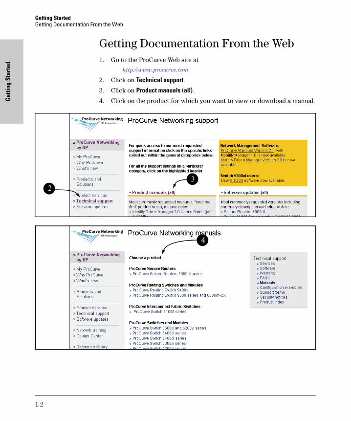
Getting Documentation From the Web1. Go to the ProCurve Web site at
http://www.procurve.com
2. Click on Technical support.
3. Click on Product manuals (all).
4. Click on the product for which you want to view or download a manual.
23
4
1-2
Getting StartedSources for More Information
Getting Started
Sources for More Information
To Set Up and Install the Switch in Your Network
Use the Installation and Getting Started Guide shipped with your switch for the following:
■ Instructions for physically installing the switch in your network.
■ Quickly assigning an IP address, subnet mask, and gateway, set a Manager password, and (optionally) configure other basic features.
■ Interpreting LED behavior.
■ Notes, cautions, and warnings related to installing and using the switch.
For the latest version of the Installation and Getting Started Guide and other documentation for your switch, visit to the ProCurve Web site. (Refer to “Getting Documentation From the Web” on page 1-2.)
1-3

Using the ProCurve W
eb B
rowser Interface
2
Using the ProCurve Web Browser Interface
Overview
This switch provides an embedded HTTP Web agent. Using a Web browser you can configure the switch and view statistics to monitor network activity. The Web agent can be accessed by any computer on the network using a standard Web browser (Internet Explorer 5.5 or above).
Prior to accessing the switch from a Web browser, be sure you have first performed the following tasks:
1. Configure the switch with a valid IP address, subnet mask, and default gateway. (Defaults: IP address 192.168.2.10; Subnet mask 255.255.255.0; Gateway 0.0.0.0)
2. Set a new password using the Web interface (the default is no password). Access to the Web interface is controlled by the password.
N o t e If you cannot remember the switch's IP address, you can restore the original settings by following the procedure described in the “Troubleshooting” section.
N o t e If the Web Browser Interface is inactive for more than 300 seconds, the Web Browser logs out the administrator and returns to the Login page.
Navigating the Web Browser Interface
Home Page
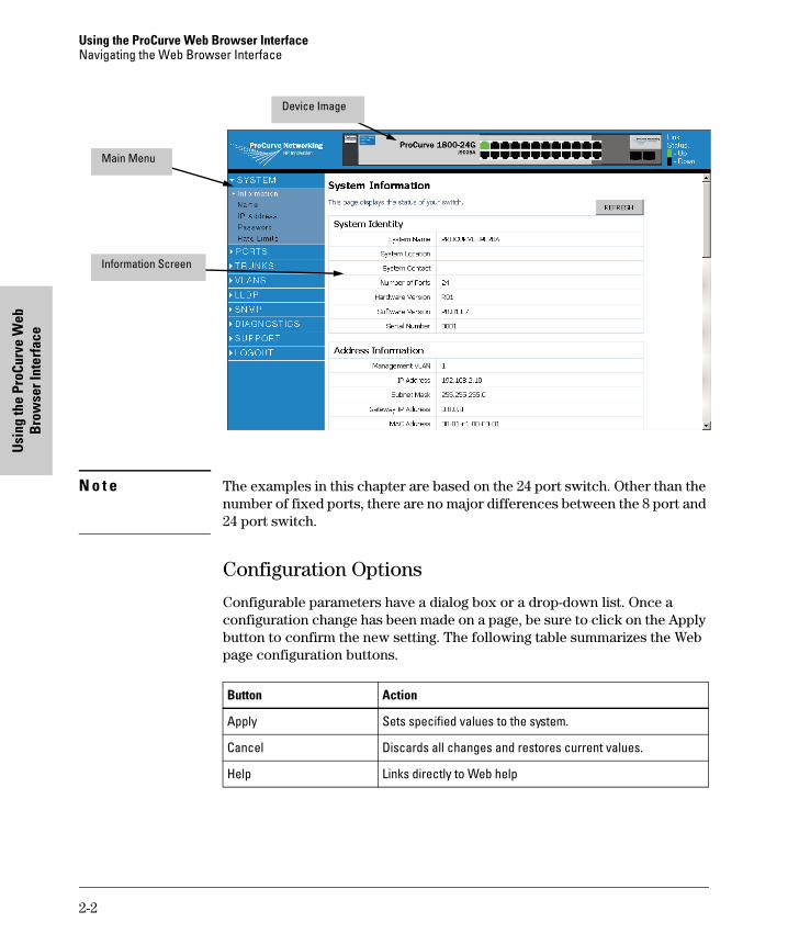
When your Web browser connects with the switch’s Web agent, the home page is displayed as shown below. The home page displays the Main Menu on the left side of the screen, System Information on the right side, and Device Image on the top bar. The Main Menu links are used to navigate to other menus, and display configuration parameters and statistics.
2-1
Using the ProCurve Web Browser InterfaceNavigating the Web Browser Interface
Usi
ng th
e Pr
oCur
ve W
eb
Bro
wse
r Int
erfa
ce
N o t e The examples in this chapter are based on the 24 port switch. Other than the number of fixed ports, there are no major differences between the 8 port and 24 port switch.
Configuration Options
Configurable parameters have a dialog box or a drop-down list. Once a configuration change has been made on a page, be sure to click on the Apply button to confirm the new setting. The following table summarizes the Web page configuration buttons.
Main Menu
Information Screen
Device Image
Button Action
Apply Sets specified values to the system.
Cancel Discards all changes and restores current values.
Help Links directly to Web help
2-2
Using the ProCurve Web Browser InterfaceNavigating the Web Browser Interface
Using the ProCurve W
eb B
rowser Interface
N o t e To ensure proper screen refresh, be sure that Internet Explorer is configured as follows: Under the menu “Tools / Internet Options / General / Temporary Internet Files / Settings,” the setting for item “Check for newer versions of stored pages” should be “Every visit to the page”.
Panel Display
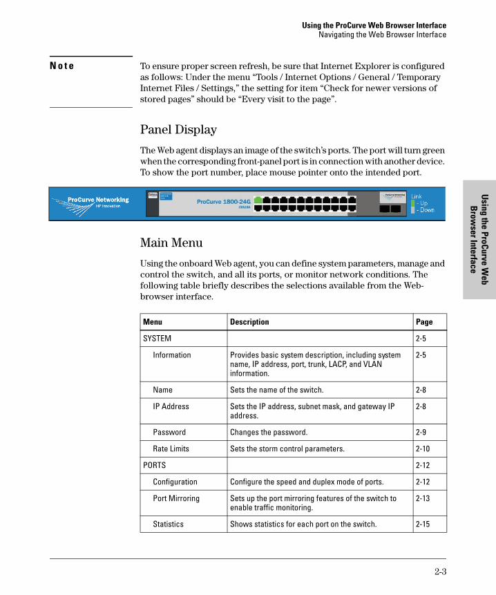
The Web agent displays an image of the switch’s ports. The port will turn green when the corresponding front-panel port is in connection with another device. To show the port number, place mouse pointer onto the intended port.
Main Menu
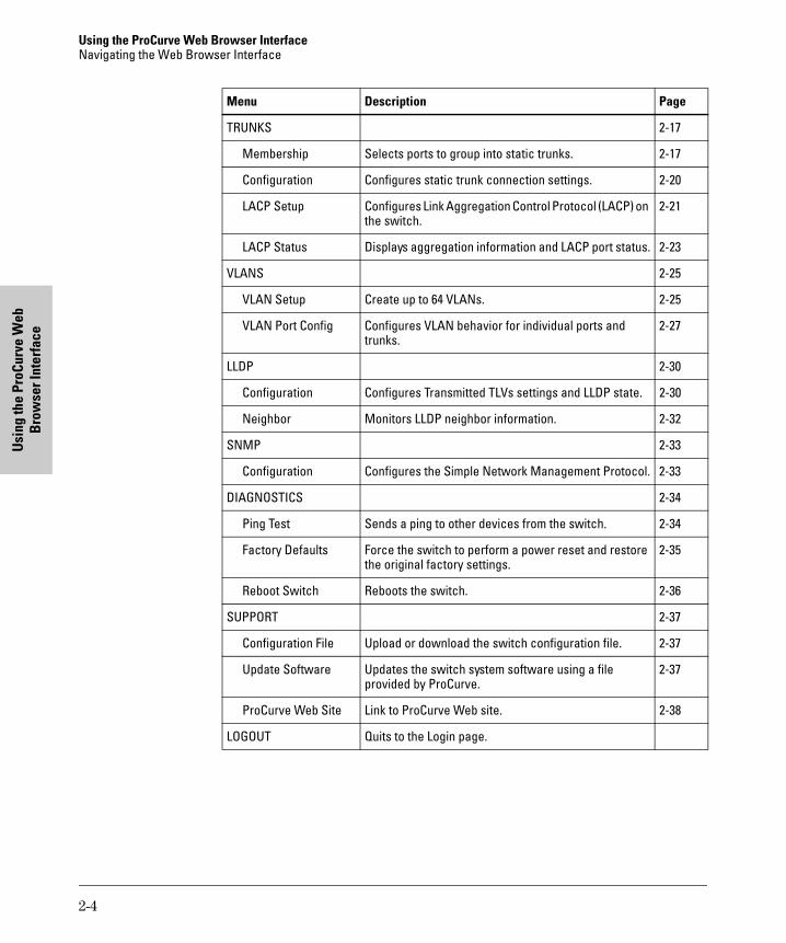
Using the onboard Web agent, you can define system parameters, manage and control the switch, and all its ports, or monitor network conditions. The following table briefly describes the selections available from the Web-browser interface.
Menu Description Page
SYSTEM 2-5
Information Provides basic system description, including system name, IP address, port, trunk, LACP, and VLAN information.
2-5
Name Sets the name of the switch. 2-8
IP Address Sets the IP address, subnet mask, and gateway IP address.
2-8
Password Changes the password. 2-9
Rate Limits Sets the storm control parameters. 2-10
PORTS 2-12
Configuration Configure the speed and duplex mode of ports. 2-12
Port Mirroring Sets up the port mirroring features of the switch to enable traffic monitoring.
2-13
Statistics Shows statistics for each port on the switch. 2-15
2-3
Using the ProCurve Web Browser InterfaceNavigating the Web Browser Interface
Usi
ng th
e Pr
oCur
ve W
eb
Bro
wse
r Int
erfa
ce
TRUNKS 2-17
Membership Selects ports to group into static trunks. 2-17
Configuration Configures static trunk connection settings. 2-20
LACP Setup Configures Link Aggregation Control Protocol (LACP) on the switch.
2-21
LACP Status Displays aggregation information and LACP port status. 2-23
VLANS 2-25
VLAN Setup Create up to 64 VLANs. 2-25
VLAN Port Config Configures VLAN behavior for individual ports and trunks.
2-27
LLDP 2-30
Configuration Configures Transmitted TLVs settings and LLDP state. 2-30
Neighbor Monitors LLDP neighbor information. 2-32
SNMP 2-33
Configuration Configures the Simple Network Management Protocol. 2-33
DIAGNOSTICS 2-34
Ping Test Sends a ping to other devices from the switch. 2-34
Factory Defaults Force the switch to perform a power reset and restore the original factory settings.
2-35
Reboot Switch Reboots the switch. 2-36
SUPPORT 2-37
Configuration File Upload or download the switch configuration file. 2-37
Update Software Updates the switch system software using a file provided by ProCurve.
2-37
ProCurve Web Site Link to ProCurve Web site. 2-38
LOGOUT Quits to the Login page.
Menu Description Page
2-4
Using the ProCurve Web Browser InterfaceWeb Configuration
Using the ProCurve W
eb B
rowser Interface
Web Configuration
Displaying System Information
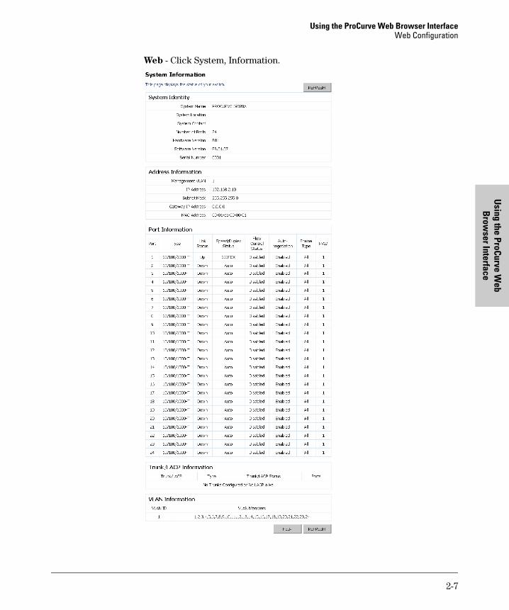
You can display a complete summary of identity, IP Address, port, Trunk/LACP, and VLAN information for the switch.
Field Attributes
System Identity
• System Name – Name assigned to the switch system.
• System Location – Description of the switch location.
• System Contact – Contact information assigned to the switch.
• Number of Ports – Number of built-in ports.
• Hardware Version – Hardware version of the main board.
• Software Version – Version number of the code.
• Serial Number – The serial number of the switch.
Address Information
• Management VLAN – ID of the configured VLAN (this is set to 1 and cannot be changed) all ports on the unit are members of VLAN 1. The management station must always be attached to a port on VLAN 1.
• IP Address – Address of the VLAN to which the management station is attached. (Note that the management station must always be on VLAN 1.)
• Subnet Mask – This mask identifies the host address bits used for routing to specific subnets. (Default: 255.255.255.0)
• Gateway IP Address – IP address of the gateway router between the switch and management stations that exist on other network segments. (Default: 0.0.0.0)
• MAC Address – The physical layer address of the switch.
Port Information
• Port – Indicates the port number.
• Type – Indicates the port type (10/100/1000T or M).
• Link Status – Indicates if the link is Up or Down.
2-5
Using the ProCurve Web Browser InterfaceWeb Configuration
Usi
ng th
e Pr
oCur
ve W
eb
Bro
wse
r Int
erfa
ce
• Speed/Duplex Status – Shows the current speed and duplex mode.– 10HDX– 10FDX– 100HDX– 100FDX– 1000FDX
• Flow Control Status – Indicates whether flow control is enabled or disabled.
• Auto-negotiation – Shows if auto-negotiation is enabled or disabled.
• Frame Type – Either “Tagged” or “All”. “Tagged” means that the port will only send and receive VLAN-tagged packets. When set to “All”, the port will also send and receive untagged packets.
• PVID – The VLAN ID assigned to untagged frames received on the interface. (Default: 1)
Trunk/LACP Information
• Trunk/LACP – The trunk label. “T1” through “T12” on the 24 port and “T1” through “T4” on the 8 port are used as trunk labels.
• Type – Displays the trunk type as "Static" or "Dynamic".
• Trunk/LACP Status – Indicates the speed and duplex setting of the trunk.– 10HDX– 10FDX– 100HDX– 100FDX– 1000FDX
• Ports – The ports that are members of the trunk.
VLAN Information
• VLAN ID – A number in the range 1 - 4094 which identifies the VLAN.
• VLAN Member – A list of the ports that are members of the VLAN. By default, all ports are members of VLAN 1.
2-6
Using the ProCurve Web Browser InterfaceWeb Configuration
Using the ProCurve W
eb B
rowser Interface
Web - Click System, Information.
2-7
Using the ProCurve Web Browser InterfaceWeb Configuration
Usi
ng th
e Pr
oCur
ve W
eb
Bro
wse
r Int
erfa
ce
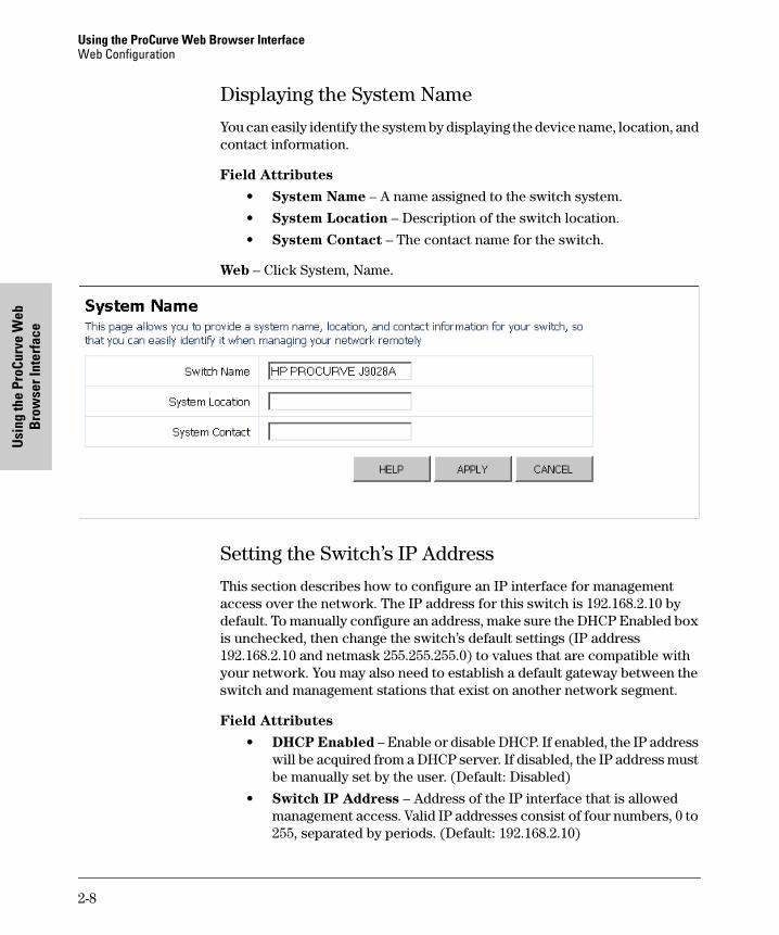
Displaying the System Name
You can easily identify the system by displaying the device name, location, and contact information.
Field Attributes
• System Name – A name assigned to the switch system.
• System Location – Description of the switch location.
• System Contact – The contact name for the switch.
Web – Click System, Name.
Setting the Switch’s IP Address
This section describes how to configure an IP interface for management access over the network. The IP address for this switch is 192.168.2.10 by default. To manually configure an address, make sure the DHCP Enabled box is unchecked, then change the switch’s default settings (IP address 192.168.2.10 and netmask 255.255.255.0) to values that are compatible with your network. You may also need to establish a default gateway between the switch and management stations that exist on another network segment.
Field Attributes
• DHCP Enabled – Enable or disable DHCP. If enabled, the IP address will be acquired from a DHCP server. If disabled, the IP address must be manually set by the user. (Default: Disabled)
• Switch IP Address – Address of the IP interface that is allowed management access. Valid IP addresses consist of four numbers, 0 to 255, separated by periods. (Default: 192.168.2.10)
2-8
Using the ProCurve Web Browser InterfaceWeb Configuration
Using the ProCurve W
eb B
rowser Interface
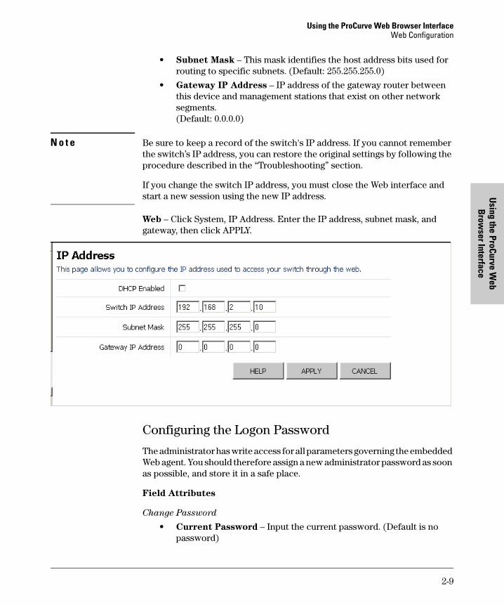
• Subnet Mask – This mask identifies the host address bits used for routing to specific subnets. (Default: 255.255.255.0)
• Gateway IP Address – IP address of the gateway router between this device and management stations that exist on other network segments.(Default: 0.0.0.0)
N o t e Be sure to keep a record of the switch's IP address. If you cannot remember the switch’s IP address, you can restore the original settings by following the procedure described in the “Troubleshooting” section.
If you change the switch IP address, you must close the Web interface and start a new session using the new IP address.
Web – Click System, IP Address. Enter the IP address, subnet mask, and gateway, then click APPLY.
Configuring the Logon Password
The administrator has write access for all parameters governing the embedded Web agent. You should therefore assign a new administrator password as soon as possible, and store it in a safe place.
Field Attributes
Change Password
• Current Password – Input the current password. (Default is no password)
2-9
Using the ProCurve Web Browser InterfaceWeb Configuration
Usi
ng th
e Pr
oCur
ve W
eb
Bro
wse
r Int
erfa
ce
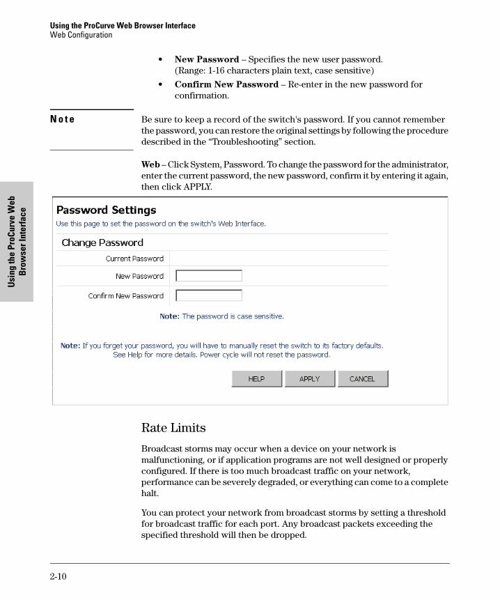
• New Password – Specifies the new user password.(Range: 1-16 characters plain text, case sensitive)
• Confirm New Password – Re-enter in the new password for confirmation.
N o t e Be sure to keep a record of the switch's password. If you cannot remember the password, you can restore the original settings by following the procedure described in the “Troubleshooting” section.
Web – Click System, Password. To change the password for the administrator, enter the current password, the new password, confirm it by entering it again, then click APPLY.
Rate Limits
Broadcast storms may occur when a device on your network is malfunctioning, or if application programs are not well designed or properly configured. If there is too much broadcast traffic on your network, performance can be severely degraded, or everything can come to a complete halt.
You can protect your network from broadcast storms by setting a threshold for broadcast traffic for each port. Any broadcast packets exceeding the specified threshold will then be dropped.
2-10

Using the ProCurve Web Browser InterfaceWeb Configuration
Using the ProCurve W
eb B
rowser Interface
Field Attributes
• Enable Rate Limits – Click to select the box to enable rate limits. (Default: Disabled)
• Limit (number of frames per second) – Threshold of port bandwidth measured in number of frames per second. From the drop down menu you can choose the desired limit. The value specifies the size of the available input bandwidth that can be made available for broadcast and multicast traffic. The same limit size is applied to every port on the switch. When the limit size is exceeded, packets are dropped, irrespective of the flow control settings.
Web – Click System, Rate Limits. This page enables you to set the broadcast storm control parameters for the switch.
2-11

Using the ProCurve Web Browser InterfaceWeb Configuration
Usi
ng th
e Pr
oCur
ve W
eb
Bro
wse
r Int
erfa
ce
Port Configuration
You can use the Port Configuration page to manually set the speed, duplex mode, and flow control. You can enable jumbo frames to support data packets 9000 bytes in size.
Field Attributes
• Enable Jumbo Frames – Click box to enable jumbo frames.
• Port – The port number.
• Speed/Duplex – Allows you to manually set the port speed and duplex mode.
• Flow Control – Allows flow control to be enabled or disabled. When the box is checked, flow control is enabled.
• Trunk – Indicates if a port is a member of a trunk.
Web – Click Ports, Configuration.
N o t e Ports within a trunk cannot be configured individually. However, you can use the Trunk Configuration page to manually set the same speed, duplex mode, and flow control for every port in a trunk.
2-12

Using the ProCurve Web Browser InterfaceWeb Configuration
Using the ProCurve W
eb B
rowser Interface
Port Mirroring
You can mirror traffic from any source port to a target port for real-time analysis. You can then attach a network analyzer or RMON probe to the target port and study the traffic crossing the source port in a completely unobtrusive manner.
Field Attributes
Port to Mirror to
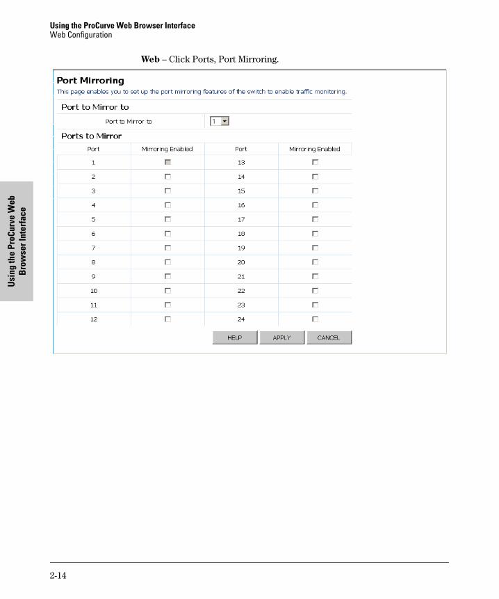
• Port to Mirror to – The port that will be use to “mirror” another port’s incoming data. Data packets will be dropped when data coming in is greater than the port can handle.
N o t e If the total ingress bandwidth exceeds the mirror port’s egress bandwidth, packets will eventually be dropped on ingress to the switch, which means they will not reach the mirror port or their intended destination port. Input rate-limiting in conjunction with port flow-control should be used to ensure that the total ingress bandwidth never exceeds the egress bandwidth.
Ports to Mirror
• Mirroring Enabled – The port whose traffic will be monitored. If enabled, the data packets on this port will be mirrored. (Default: Disabled)
2-13
Using the ProCurve Web Browser InterfaceWeb Configuration
Usi
ng th
e Pr
oCur
ve W
eb
Bro
wse
r Int
erfa
ce
Web – Click Ports, Port Mirroring.
2-14
Using the ProCurve Web Browser InterfaceWeb Configuration
Using the ProCurve W
eb B
rowser Interface
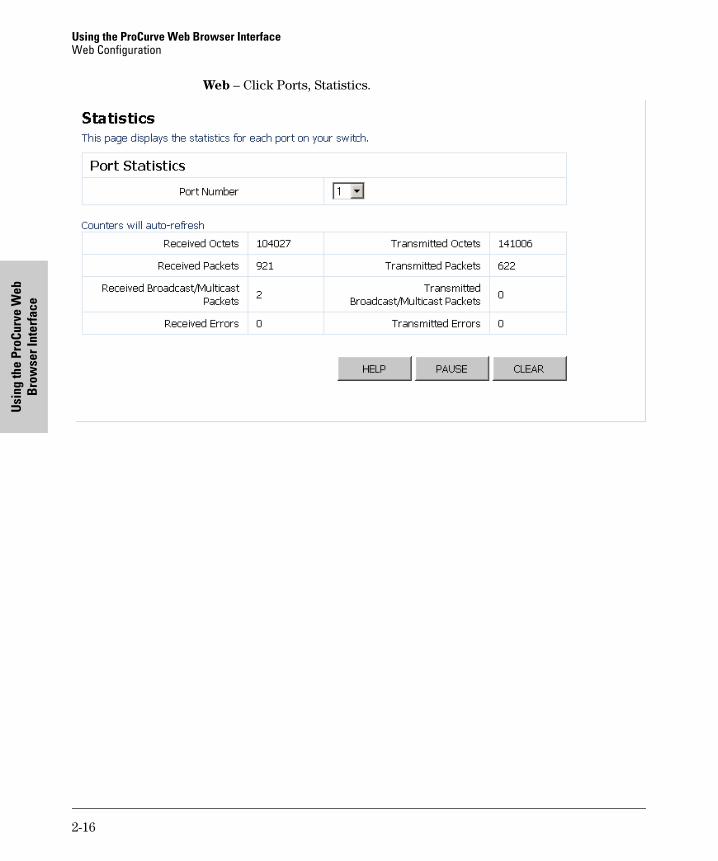
Showing Port Statistics
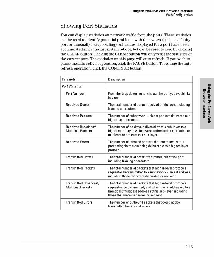
You can display statistics on network traffic from the ports. These statistics can be used to identify potential problems with the switch (such as a faulty port or unusually heavy loading). All values displayed for a port have been accumulated since the last system reboot, but can be reset to zero by clicking the CLEAR button. Clicking the CLEAR button will only reset the statistics of the current port. The statistics on this page will auto-refresh. If you wish to pause the auto-refresh operation, click the PAUSE button. To resume the auto-refresh operation, click the CONTINUE button.
Parameter Description
Port Statistics
Port Number From the drop down menu, choose the port you would like to view.
Received Octets The total number of octets received on the port, including framing characters.
Received Packets The number of subnetwork-unicast packets delivered to a higher-layer protocol.
Received Broadcast/Multicast Packets
The number of packets, delivered by this sub-layer to a higher (sub-)layer, which were addressed to a broadcast/multicast address at this sub-layer.
Received Errors The number of inbound packets that contained errors preventing them from being deliverable to a higher-layer protocol.
Transmitted Octets The total number of octets transmitted out of the port, including framing characters.
Transmitted Packets The total number of packets that higher-level protocols requested be transmitted to a subnetwork-unicast address, including those that were discarded or not sent.
Transmitted Broadcast/Multicast Packets
The total number of packets that higher-level protocols requested be transmitted, and which were addressed to a broadcast/multicast address at this sub-layer, including those that were discarded or not sent.
Transmitted Errors The number of outbound packets that could not be transmitted because of errors.
2-15
Using the ProCurve Web Browser InterfaceWeb Configuration
Usi
ng th
e Pr
oCur
ve W
eb
Bro
wse
r Int
erfa
ce
Web – Click Ports, Statistics.
2-16

Using the ProCurve Web Browser InterfaceWeb Configuration
Using the ProCurve W
eb B
rowser Interface
Trunk Membership
This page allows you to create static trunks. Trunking allows you to assign physical links to one logical link (trunk) that functions as a single, higher-speed link providing dramatically increased bandwidth. This capability applies to connections between backbone devices as well as to connections in other network areas where traffic bottlenecks exist.
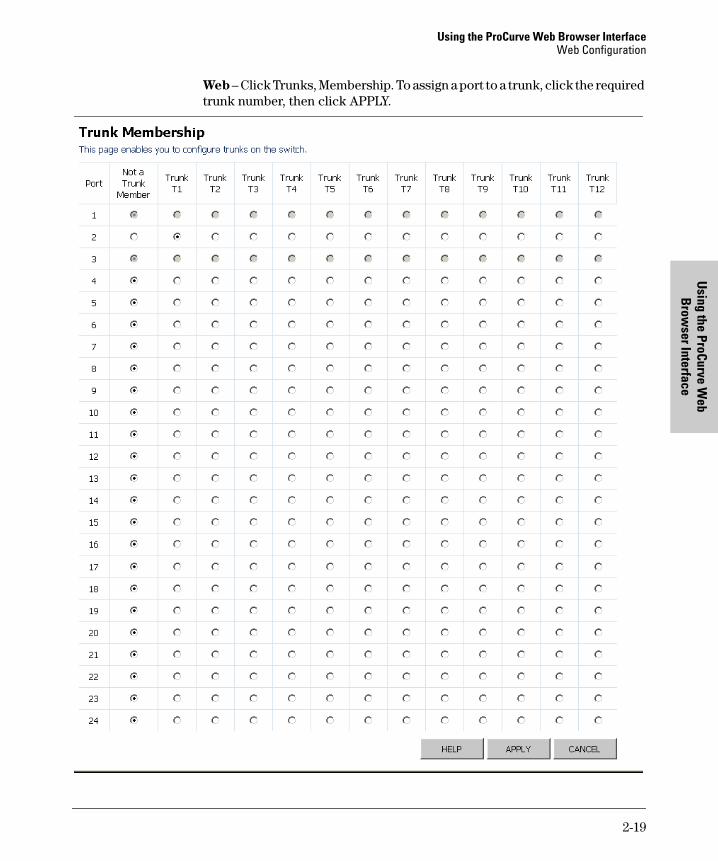
The Membership Table has one row for each port and a column for each trunk, plus an additional column for ports that are not members of a trunk. Each row contains radio buttons which are used to indicate which trunk (if any) the port belongs to.
Defining the Members of a Trunk
1. On the Trunks Membership page, click on the radio button in any one of these columns of the corresponding trunk.
For example, if you want ports 2, 3, 4, and 5 to become members of Trunk 2, click the radio buttons for 2, 3, 4, and 5 under the column labeled “Trunk T2”.
2. Click APPLY.
Deleting the Members of a Trunk
1. On the Trunks Membership page, click on the radio button under the column labeled “Not a Trunk Member” for any port you want to remove from a trunk. To delete a trunk, remove all port members from that trunk.
For example, if you want to remove ports 2, 3, 4, and 5 from Trunk 2, click the radio buttons for 2, 3, 4, and 5 under the column labeled “Not a Trunk Member”.
2. Click APPLY.
N o t e For the 8 port switch, you can only create up to a maximum of 4 trunks of up to 8 ports each.
Port Trunking Support ProCurve 1800-8G ProCurve-24G
Ports per trunk (maximum) 8 8
Trunks per switch (maximum) 4 12
2-17

Using the ProCurve Web Browser InterfaceWeb Configuration
Usi
ng th
e Pr
oCur
ve W
eb
Bro
wse
r Int
erfa
ce
Field Attributes
• Port – The port number.
• Not a Trunk Member – If the radio button in this column is selected, the port is not a member of any trunks. This is the default state.
• Trunk T1-T12 – These columns correspond to the trunks that are supported by the switch. To assign a port to a trunk, click on the radio button in any one of these columns of the corresponding trunk and then click APPLY.
2-18
Using the ProCurve Web Browser InterfaceWeb Configuration
Using the ProCurve W
eb B
rowser Interface
Web – Click Trunks, Membership. To assign a port to a trunk, click the required trunk number, then click APPLY.
2-19

Using the ProCurve Web Browser InterfaceWeb Configuration
Usi
ng th
e Pr
oCur
ve W
eb
Bro
wse
r Int
erfa
ce
Trunk Configuration
You can use the Trunk Configuration page to manually set the speed, duplex mode, and flow control.
Modifying Trunk Settings
1. On the Trunks Configuration page, modify any of the following settings:
• Speed Duplex – Allows auto-negotiation to be enabled or disabled. When auto-negotiation is disabled, you can force the settings for speed, duplex mode, and flow control.
• Flow Control – Allows automatic or manual selection of flow control.
2. Click APPLY.
N o t e All the ports in the trunk will have the same speed, duplex mode, and flow control as defined by the trunk. Once the trunk is deleted, the ports will no longer be a member of that trunk but will retain the speed, duplex mode, and flow control setting of that trunk.
Field Attributes
• Trunk – Indicates trunk identification.
• Speed/Duplex – Allows you to manually set the port speed and duplex mode for all ports in the trunk.
• Flow Control – Allows flow control to be enabled or disabled. When the box is checked, flow control is enabled.
• Member Ports – Indicates which ports belong to the trunk.
Web – Click Trunks, Configuration.
2-20
Using the ProCurve Web Browser InterfaceWeb Configuration
Using the ProCurve W
eb B
rowser Interface
LACP Settings
The switch supports both static trunking and dynamic Link Aggregation Control Protocol (LACP), which is specified in IEEE 802.3ad. Static trunks have to be manually configured at both ends of the link, on the other hand, LACP configured ports can automatically negotiate a trunked link with LACP-configured ports on another device. You can configure any number of ports on the switch as LACP, as long as they are not already configured as part of a static trunk. If ports on another device are also configured as LACP, the switch and the other device will negotiate a trunk link between them. If an LACP trunk consists of more than four ports, all other ports will be placed in a standby mode. Should one link in the trunk fail, one of the standby ports will automatically be activated to replace it.
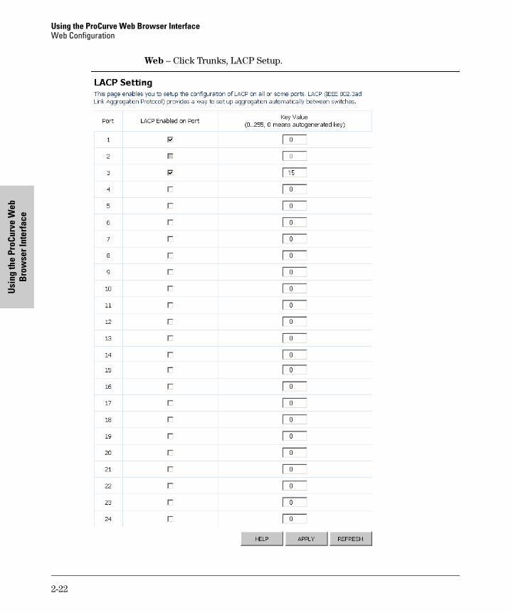
You can use the LACP Setting page to configure LACP for each port.
Enabling LACP
1. On the LACP Setting page, click the box under the column labeled “LACP Enabled on Port” for the ports you want to enable LACP.
2. Input a key value for the Link Aggregate Group.
3. Click APPLY.
Disabling LACP
1. On the LACP Setting page, click the box under the column labeled “LACP Enabled on Port” to remove the check mark for the ports you want to disable LACP.
2. Click APPLY.
Field Attributes
• Port – The port number.
• LACP Enabled on Port – Allows LACP to be enabled or disabled. When the box is checked, LACP is enabled.
• Key Value (0..255, 0 means autogenerated key) – Ports in an aggregated link group must have the same LACP port Key. For a port to be allowed to join an aggregated group, the port Key must be set to the same value. When set to zero, the port Key is automatically set by the switch.
2-21
Using the ProCurve Web Browser InterfaceWeb Configuration
Usi
ng th
e Pr
oCur
ve W
eb
Bro
wse
r Int
erfa
ce
Web – Click Trunks, LACP Setup.
2-22

Using the ProCurve Web Browser InterfaceWeb Configuration
Using the ProCurve W
eb B
rowser Interface
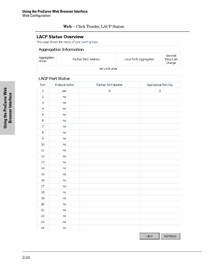
LACP Status
Displays the status of the LACP groups.
Field Attributes
Aggregation Information
• Aggregation Group – Displays the ID number of the LACP group.
• Partner MAC Address – Displays the MAC address of a device in the LACP group that is attached to this switch.
• Local Port Aggregated – Displays port member list of the local LACP group. The port members are port on this switch.
• Seconds Since Last Changed – Number of seconds since the last LACP was received.
LACP Port Status
• Port – The port number.
• Protocol Active – Indicates if the port is a member of an active LACP group.
• Partner Port Number – A list of port numbers assigned to the link by the LACP partner.
• Operation Port Key – The current operational value of the key for the LACP group.
2-23
Using the ProCurve Web Browser InterfaceWeb Configuration
Usi
ng th
e Pr
oCur
ve W
eb
Bro
wse
r Int
erfa
ce
Web – Click Trunks, LACP Status.
2-24
Using the ProCurve Web Browser InterfaceWeb Configuration
Using the ProCurve W
eb B
rowser Interface
VLAN Setup
This page allows you to create up to 64 VLANs based on the 802.1Q standard. You can also delete or modify VLANs.
Introduction to VLANs
VLANs are logical partitions of the physical LAN. You can use VLANs to increase network performance, improve internal network security, or create separate broadcast domains.
If the network has adequate performance and security for your current needs, it is recommended that you leave the VLAN settings in the default configuration. The default configuration is as follows:
• All ports are members of VLAN 1
• The switch management interface is on VLAN 1 (this cannot be changed)
• All ports have a Port VLAN ID (PVID) of 1
• All ports can send and receive both VLAN-tagged and untagged packets (that is, they are hybrid ports)
In the default configuration, any port is able to send traffic to any other port, and a PC connected to any port will be able to access the management interface. Broadcast traffic, for example, will be flooded to all ports on the switch.
The four VLAN parameters you can configure for each port on the switch include VLAN Aware Enabled, Ingress Filtering Enabled, Packet Type, and PVID. Note that the ports within a trunk cannot be configured individually; configure the trunk instead (trunks are labelled T1 to T12 for the 24 port switch, and T1 to T4 for the 8 port switch).
Creating a VLAN
1. Use the VLAN Setup page to create VLANs on the Switch. In VLAN ID, input a number from 1 to 4094.
2. Click ADD.
3. Select the ports to be a member of this VLAN.
4. Click APPLY.
2-25
Using the ProCurve Web Browser InterfaceWeb Configuration
Usi
ng th
e Pr
oCur
ve W
eb
Bro
wse
r Int
erfa
ce
Modifying a VLAN
1. Use the VLAN Setup page to modify a VLAN. Under the VLAN List section, click on the radio button of the VLAN you would like to modify.
2. Click MODIFY.
3. Select the ports to be added to or removed from this VLAN.
4. Click APPLY.
Deleting a VLAN
1. Use the VLAN Setup page to delete a VLAN. Under the VLAN List section, click on the radio button of the VLAN you would like to delete.
2. Click DELETE.
N o t e Before deleting a VLAN, make sure that all the ports in this VLAN are also a member of another VLAN. Otherwise, the port will not be a member of any VLAN.
Field Attributes
Add VLAN
• VLAN ID – Input a VLAN ID and click APPLY to create a new VLAN.
VLAN List
• VLAN List – The list of up to 64 VLANs. You can modify or delete these VLANs.
2-26

Using the ProCurve Web Browser InterfaceWeb Configuration
Using the ProCurve W
eb B
rowser Interface
Web – Click VLANS, VLAN Setup.
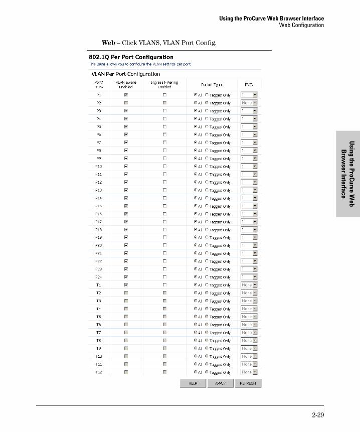
VLAN Port Config
You can configure VLAN behavior for specific interfaces, including the default VLAN identifier (PVID) and accepted frame types. This page allows you to change the VLAN membership and behavior of individual ports. Each row of the table corresponds to one port or trunk; trunked ports cannot be configured individually.
Field Attributes
VLAN Per Port Configuration
• Port/Trunk – The port number or the ID of a trunk.
2-27

Using the ProCurve Web Browser InterfaceWeb Configuration
Usi
ng th
e Pr
oCur
ve W
eb
Bro
wse
r Int
erfa
ce
• VLAN Aware Enabled – VLAN aware ports are able to use VLAN tagged frames to determine the destination of the frame. Click to enable or disable VLAN awareness mode for this port. (Default: Enabled)
• Ingress Filtering Enabled – If enabled, incoming frames for VLANs which do not include this ingress port in their member set will be discarded. (Default: Disabled)
• Packet Type – Users can set the interface to accept all frame types, or only tagged frames.
If the Packet Type is set to “All,” the port can accept incoming tagged and untagged packets. Untagged packets will be associated with the VLAN identified by the PVID. Tagged packets will be dropped unless the port is a member of the VLAN identified by the VLAN tag in the packet.
If the Packet Type is set to “Tagged,” the port will only send tagged packets. (Default: All)
• PVID – From a drop down menu, choose the VLAN ID that will be assigned to untagged frames received on this port. You cannot choose “None” for the VLAN ID unless the packet type is set to “Tagged Only.” Choosing “None” will not assign any VLAN ID to untagged frames received on this port. It is not possible to remove a port from VLAN 1 unless its PVID has been changed to something other than 1. The PVID has no effect on ports that have Packet Type set to Tagged. (Default: 1)
2-28
Using the ProCurve Web Browser InterfaceWeb Configuration
Using the ProCurve W
eb B
rowser Interface
Web – Click VLANS, VLAN Port Config.
2-29
Using the ProCurve Web Browser InterfaceWeb Configuration
Usi
ng th
e Pr
oCur
ve W
eb
Bro
wse
r Int
erfa
ce
LLDP Configuration
This page allows you to configure the Link Layer Discovery Protocol (LLDP) configuration. LLDP allows devices on the network to share information about themselves for the reasons of simplified troubleshooting, enhanced network management, and maintaining an accurate network topology. LLDP-capable devices periodically transmit information in messages called Type Length Value (TLV) fields to neighbor devices.
Field Attributes
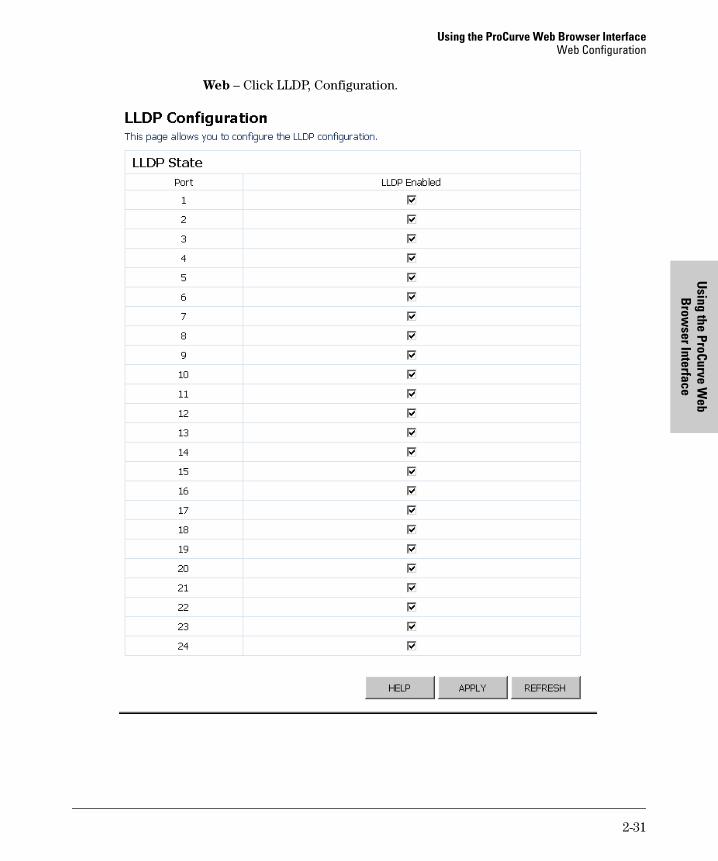
LLDP State
• Port – The port number.
• State – You can choose to disable or enable LLDP for each port. Enabling LLDP will allow the port to receive and transmit TLVs.
2-30
Using the ProCurve Web Browser InterfaceWeb Configuration
Using the ProCurve W
eb B
rowser Interface
Web – Click LLDP, Configuration.
2-31
Using the ProCurve Web Browser InterfaceWeb Configuration
Usi
ng th
e Pr
oCur
ve W
eb
Bro
wse
r Int
erfa
ce
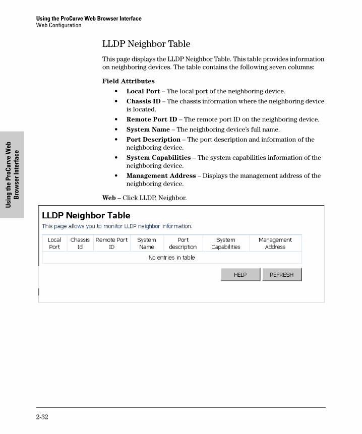
LLDP Neighbor Table
This page displays the LLDP Neighbor Table. This table provides information on neighboring devices. The table contains the following seven columns:
Field Attributes
• Local Port – The local port of the neighboring device.
• Chassis ID – The chassis information where the neighboring device is located.
• Remote Port ID – The remote port ID on the neighboring device.
• System Name – The neighboring device’s full name.
• Port Description – The port description and information of the neighboring device.
• System Capabilities – The system capabilities information of the neighboring device.
• Management Address – Displays the management address of the neighboring device.
Web – Click LLDP, Neighbor.
2-32
Using the ProCurve Web Browser InterfaceWeb Configuration
Using the ProCurve W
eb B
rowser Interface
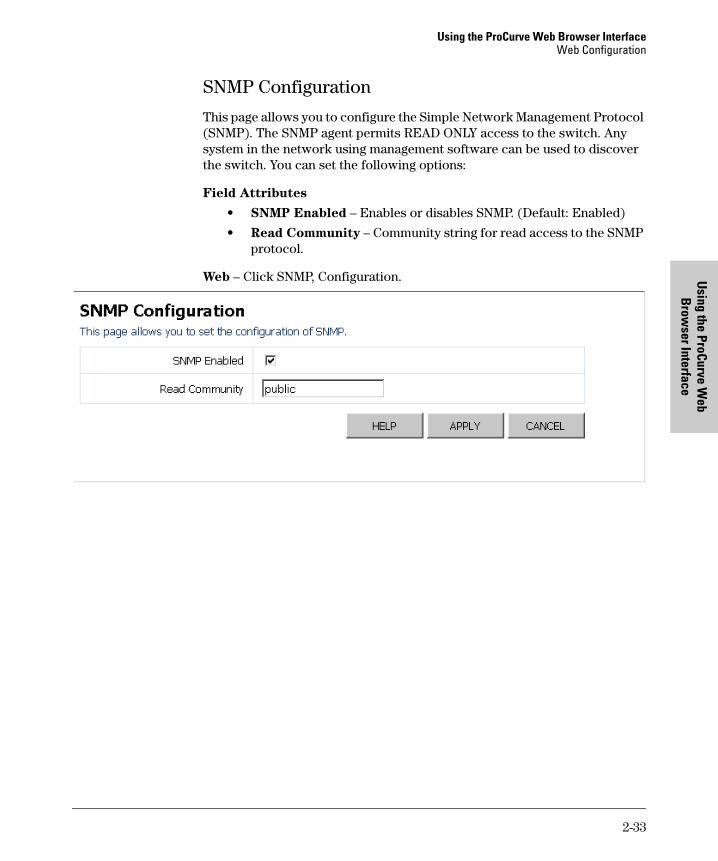
SNMP Configuration
This page allows you to configure the Simple Network Management Protocol (SNMP). The SNMP agent permits READ ONLY access to the switch. Any system in the network using management software can be used to discover the switch. You can set the following options:
Field Attributes
• SNMP Enabled – Enables or disables SNMP. (Default: Enabled)
• Read Community – Community string for read access to the SNMP protocol.
Web – Click SNMP, Configuration.
2-33

Using the ProCurve Web Browser InterfaceWeb Configuration
Usi
ng th
e Pr
oCur
ve W
eb
Bro
wse
r Int
erfa
ce
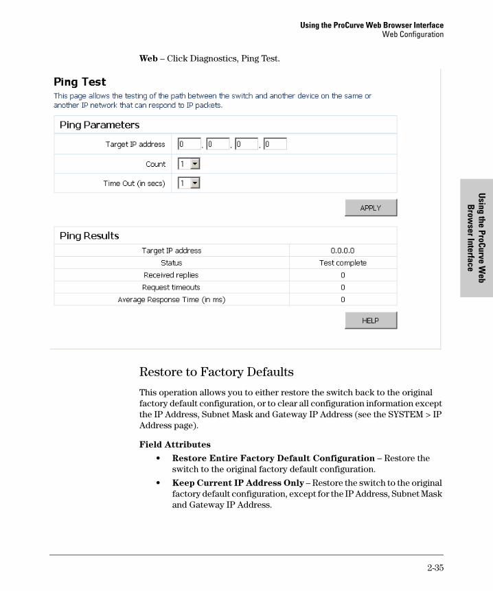
Ping Test
This operation allows you to test the network connections by sending an Internet Control Message Protocol (ICMP) echo request packet from the switch to other devices on the network. The page will display the results of the operation.
Field Attributes
Ping Parameters
• Target IP Address – The IP address of the device to ping on the network.
• Count – Number of packets to send. (Default: 1)
• Time Out (in secs) – Number of seconds to wait for a response. (Default: 1)
Ping Results
• Target IP Address – The IP address of the device to ping on the network.
• Status – Displays the current status of the ping operation.
• Received replies – Number of replies received.
• Request timeouts – Number of times the network device failed to respond in the given time.
• Average Response Time (in ms) – Average response time of all the packets.
2-34
Using the ProCurve Web Browser InterfaceWeb Configuration
Using the ProCurve W
eb B
rowser Interface
Web – Click Diagnostics, Ping Test.
Restore to Factory Defaults
This operation allows you to either restore the switch back to the original factory default configuration, or to clear all configuration information except the IP Address, Subnet Mask and Gateway IP Address (see the SYSTEM > IP Address page).
Field Attributes
• Restore Entire Factory Default Configuration – Restore the switch to the original factory default configuration.
• Keep Current IP Address Only – Restore the switch to the original factory default configuration, except for the IP Address, Subnet Mask and Gateway IP Address.
2-35
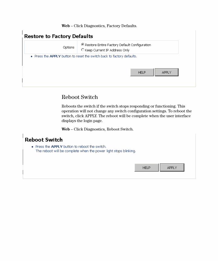
Web – Click Diagnostics, Factory Defaults.
Reboot Switch
Reboots the switch if the switch stops responding or functioning. This operation will not change any switch configuration settings. To reboot the switch, click APPLY. The reboot will be complete when the user interface displays the login page.
Web – Click Diagnostics, Reboot Switch.
Using the ProCurve Web Browser InterfaceWeb Configuration
Using the ProCurve W
eb B
rowser Interface
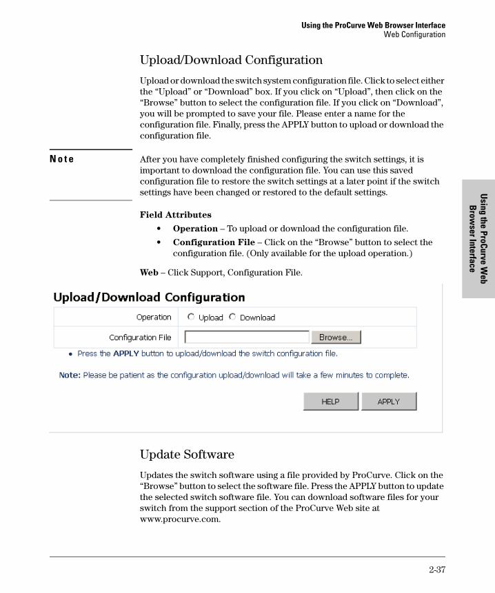
Upload/Download Configuration
Upload or download the switch system configuration file. Click to select either the “Upload” or “Download” box. If you click on “Upload”, then click on the “Browse” button to select the configuration file. If you click on “Download”, you will be prompted to save your file. Please enter a name for the configuration file. Finally, press the APPLY button to upload or download the configuration file.
N o t e After you have completely finished configuring the switch settings, it is important to download the configuration file. You can use this saved configuration file to restore the switch settings at a later point if the switch settings have been changed or restored to the default settings.
Field Attributes
• Operation – To upload or download the configuration file.
• Configuration File – Click on the “Browse” button to select the configuration file. (Only available for the upload operation.)
Web – Click Support, Configuration File.
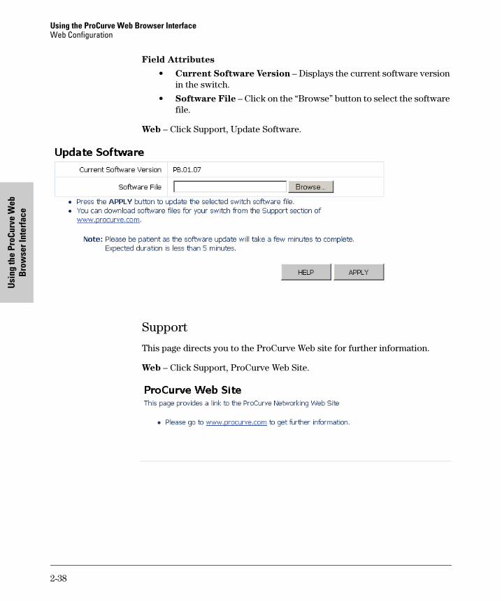
Update Software
Updates the switch software using a file provided by ProCurve. Click on the “Browse” button to select the software file. Press the APPLY button to update the selected switch software file. You can download software files for your switch from the support section of the ProCurve Web site at www.procurve.com.
2-37
Using the ProCurve Web Browser InterfaceWeb Configuration
Usi
ng th
e Pr
oCur
ve W
eb
Bro
wse
r Int
erfa
ce
Field Attributes
• Current Software Version – Displays the current software version in the switch.
• Software File – Click on the “Browse” button to select the software file.
Web – Click Support, Update Software.
Support
This page directs you to the ProCurve Web site for further information.
Web – Click Support, ProCurve Web Site.
2-38
Troubleshooting
3
Troubleshooting
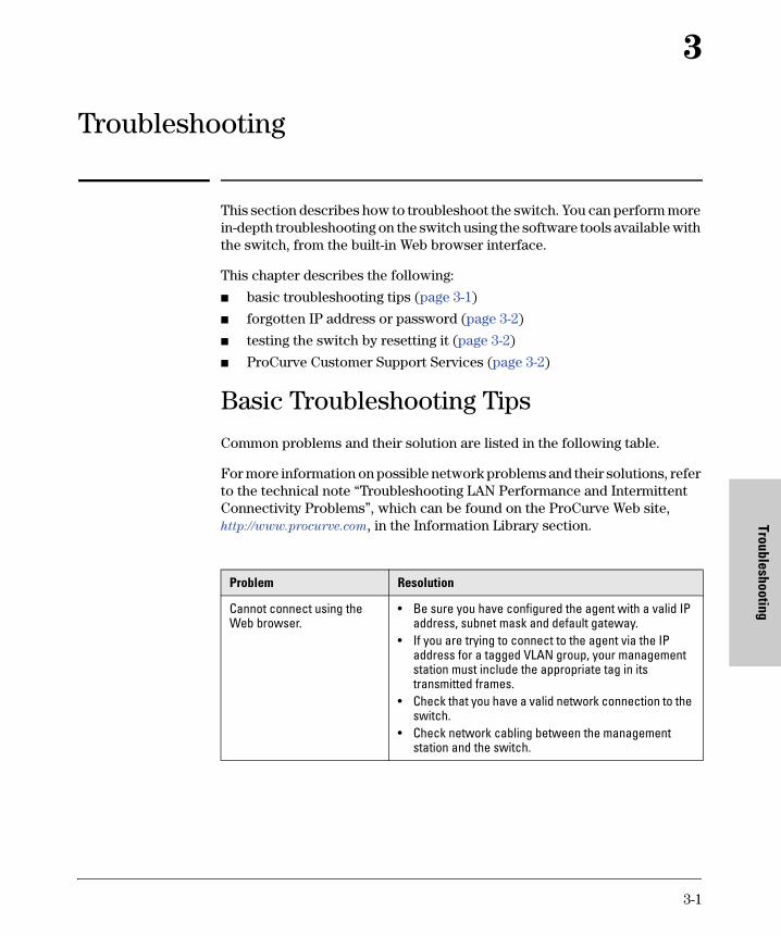
This section describes how to troubleshoot the switch. You can perform more in-depth troubleshooting on the switch using the software tools available with the switch, from the built-in Web browser interface.
This chapter describes the following:
■ basic troubleshooting tips (page 3-1)
■ forgotten IP address or password (page 3-2)
■ testing the switch by resetting it (page 3-2)
■ ProCurve Customer Support Services (page 3-2)
Basic Troubleshooting Tips
Common problems and their solution are listed in the following table.
For more information on possible network problems and their solutions, refer to the technical note “Troubleshooting LAN Performance and Intermittent Connectivity Problems”, which can be found on the ProCurve Web site, http://www.procurve.com, in the Information Library section.
Problem Resolution
Cannot connect using the Web browser.
• Be sure you have configured the agent with a valid IP address, subnet mask and default gateway.
• If you are trying to connect to the agent via the IP address for a tagged VLAN group, your management station must include the appropriate tag in its transmitted frames.
• Check that you have a valid network connection to the switch.
• Check network cabling between the management station and the switch.
3-1

TroubleshootingForgotten IP Address or Password
Trou
bles
hoot
ing
Forgotten IP Address or PasswordIf you have forgotten the switch’s IP address or administration password you can return the switch to its factory default state by following these steps:
1. Remove the power cord from the back of the switch.
2. Connect port 1 to port 2 on the front panel, using a standard network cable.
3. Reconnect the power cord to the rear of the switch.
4. Wait at least 40 seconds before disconnecting port 1 from port 2.
After completing this procedure, the password will be empty, the network address will be returned to the default 192.168.2.10, and all configuration settings will be returned to the original factory defaults.
Testing the Switch by Resetting ItIf you believe the switch is not operating correctly, you can reset the switch to test its circuitry and operating code. To reset a switch, unplug and plug in the power cord (power cycling)
Power cycling the switch cause the switch to perform its power-on self test, which almost always will resolve any temporary operational problems.
ProCurve Customer Support ServicesIf you are still having trouble with your switch, ProCurve offers support 24 hours a day, seven days a week through the use of a number of automated electronic services. See the Customer Support/Warranty booklet that came with your switch for information on how to use these services to get technical support. The ProCurve Web site, http://www.procurve.com also provides up-to-date support information.
Additionally, your ProCurve authorized network reseller can provide you with assistance, both with services they offer and with services offered by ProCurve.
3-2
TroubleshootingProCurve Customer Support Services
Troubleshooting
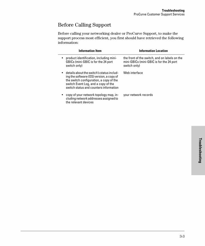
Before Calling Support
Before calling your networking dealer or ProCurve Support, to make the support process most efficient, you first should have retrieved the following information:
Information Item Information Location
• product identification, including mini-GBICs (mini-GBIC is for the 24 port switch only)
the front of the switch, and on labels on the mini-GBICs (mini-GBIC is for the 24 port switch only)
• details about the switch’s status includ-ing the software (OS) version, a copy of the switch configuration, a copy of the switch Event Log, and a copy of the switch status and counters information
Web interface
• copy of your network topology map, in-cluding network addresses assigned to the relevant devices
your network records
3-3


Index
Index
A
administrator password … 2-9
B
basic troubleshooting tips … 3-1blinking LEDs
error indications … 3-2broadcast storm … 2-10
C
Configuration fileupload/download … 2-37
D
default settings … 2-35DHCP … 2-8
H
hardware version, displaying … 2-5
I
ingress filtering … 2-28IP address
DHCP … 2-8setting … 2-8
L
LEDserror indications … 3-2
LLDPconfiguration … 2-30neighbor table … 2-32
log inWeb interface … 2-1
M
main menu … 2-3
mirror port, configuring … 2-13
P
Password … 2-9passwords
administrator setting … 2-9ports
broadcast storm, threshold … 2-10configuring … 2-12mirroring … 2-13statistics … 2-15
R
rate limits, setting … 2-10reboot switch … 2-36
S
SNMPconfiguration … 2-33
software version, displaying … 2-5software, update … 2-37statistics
port … 2-15statistics, switch … 2-5System Information … 2-5
T
tips for troubleshooting … 3-1troubleshooting … 3-1
basic tips … 3-1common network problems … 3-1
trunkconfiguration … 2-20LACP Setting … 2-21LACP status … 2-23membership … 2-17
U
updating software … 2-37
Index-1

Inde
x
user password … 2-9
V
VLANsport configuration … 2-27setup … 2-25
W
Web interfaceconfiguration options … 2-2home page … 2-1main menu … 2-3panel display … 2-3
Index-2


Technical information in this document is subject to change without notice.
© Copyright 2006
Hewlett-Packard Development Company, L.P. Reproduction, adaptation, or translation without prior written permission is prohibited except as allowed under the copyright laws.
Manual Part Number5991-4726October 2006
*5991-4726*