Embed Size (px)
Citation preview

Prodigy� Color-on-Demand� System
Customer Product ManualPart 1081750A02
Issued 11/07
NORDSON CORPORATION • AMHERST, OHIO • USA
For parts and technical support, call the Finishing Customer Support Center at (800) 433-9319.
This document is available on the Internet at http://emanuals.nordson.com/finishing
Part 1081750A02 � 2007 Nordson Corporation
Table of Contents
Introduction 1. . . . . . . . . . . . . . . . . . . . . . . . . . . . . . . . . System Manuals 1. . . . . . . . . . . . . . . . . . . . . . . . . . . SIngle Gun System 1. . . . . . . . . . . . . . . . . . . . . . . . . Dual Gun System 2. . . . . . . . . . . . . . . . . . . . . . . . . .
System Components 3. . . . . . . . . . . . . . . . . . . . . . . . . Installation 4. . . . . . . . . . . . . . . . . . . . . . . . . . . . . . . . . .
Specifications 4. . . . . . . . . . . . . . . . . . . . . . . . . . . . . . System Pump Stand Installation 4. . . . . . . . . . . . . . Controller Installation 5. . . . . . . . . . . . . . . . . . . . . . .
Pump Stand Mounting 5. . . . . . . . . . . . . . . . . . . . Wall or Panel Mounting 5. . . . . . . . . . . . . . . . . . . Rail Mounting 5. . . . . . . . . . . . . . . . . . . . . . . . . . . Grounding 5. . . . . . . . . . . . . . . . . . . . . . . . . . . . . .
Connection Diagram (Rear View of System) 6. . . System Power , Ground, and Gun Controller Connections 7. . . . . . . . . . . . . . . . . System Air Supply and Gun Air Connections 8. . . Color-On-Demand Controller and Foot Switch Connections 9. . . . . . . . . . . . . . . . . . . . Ethernet Cable Termination 10. . . . . . . . . . . . . . . . . . Delivery Tubing Installation 13. . . . . . . . . . . . . . . . . . Suction and Dump Tubing Installation 14. . . . . . . . . Remote Color Selection and Color Change Start 15. . . . . . . . . . . . . . . . . . . . . . . . .
Contact UsNordson Corporation welcomes requests for information, comments, andinquiries about its products. General information about Nordson can befound on the Internet using the following address:http://www.nordson.com.Address all correspondence to:
Nordson CorporationAttn: Customer Service555 Jackson StreetAmherst, OH 44001
NoticeThis is a Nordson Corporation publication which is protected by copyright.Original copyright date 2007. No part of this document may bephotocopied, reproduced, or translated to another language without theprior written consent of Nordson Corporation. The information containedin this publication is subject to change without notice.
Trademarks
Nordson and the Nordson logo are registered trademarks of NordsonCorporation.
Prodigy and Color-on-Demand are trademarks of Nordson Corporation.
Prodigy� Color-on-Demand� System Installation 1
Part 1081750A02� 2007 Nordson Corporation
Prodigy� Color-on-Demand� System Installation
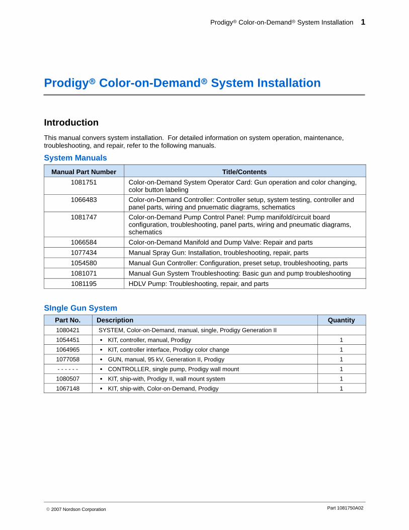
Introduction
This manual convers system installation. For detailed information on system operation, maintenance,troubleshooting, and repair, refer to the following manuals.
System Manuals
Manual Part Number Title/Contents
1081751 Color-on-Demand System Operator Card: Gun operation and color changing,color button labeling
1066483 Color-on-Demand Controller: Controller setup, system testing, controller andpanel parts, wiring and pnuematic diagrams, schematics
1081747 Color-on-Demand Pump Control Panel: Pump manifold/circuit boardconfiguration, troubleshooting, panel parts, wiring and pneumatic diagrams,schematics
1066584 Color-on-Demand Manifold and Dump Valve: Repair and parts
1077434 Manual Spray Gun: Installation, troubleshooting, repair, parts
1054580 Manual Gun Controller: Configuration, preset setup, troubleshooting, parts
1081071 Manual Gun System Troubleshooting: Basic gun and pump troubleshooting
1081195 HDLV Pump: Troubleshooting, repair, and parts
SIngle Gun System Part No. Description Quantity1080421 SYSTEM, Color-on-Demand, manual, single, Prodigy Generation II
1054451 � KIT, controller, manual, Prodigy 1
1064965 � KIT, controller interface, Prodigy color change 1
1077058 � GUN, manual, 95 kV, Generation II, Prodigy 1
- - - - - - � CONTROLLER, single pump, Prodigy wall mount 1
1080507 � KIT, ship-with, Prodigy II, wall mount system 1
1067148 � KIT, ship-with, Color-on-Demand, Prodigy 1
Prodigy� Color-on-Demand� System Installation2
Part 1081750A02 � 2007 Nordson Corporation
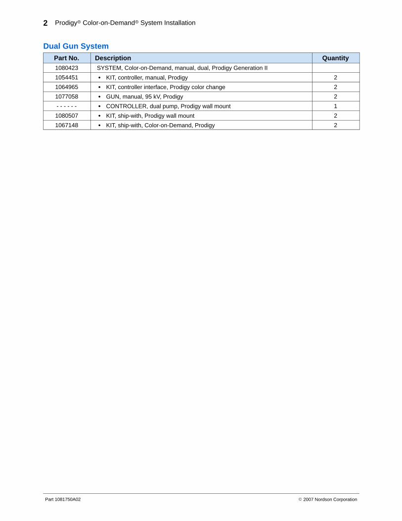
Dual Gun System Part No. Description Quantity1080423 SYSTEM, Color-on-Demand, manual, dual, Prodigy Generation II
1054451 � KIT, controller, manual, Prodigy 2
1064965 � KIT, controller interface, Prodigy color change 2
1077058 � GUN, manual, 95 kV, Prodigy 2
- - - - - - � CONTROLLER, dual pump, Prodigy wall mount 1
1080507 � KIT, ship-with, Prodigy wall mount 2
1067148 � KIT, ship-with, Color-on-Demand, Prodigy 2
Prodigy� Color-on-Demand� System Installation 3
Part 1081750A02� 2007 Nordson Corporation
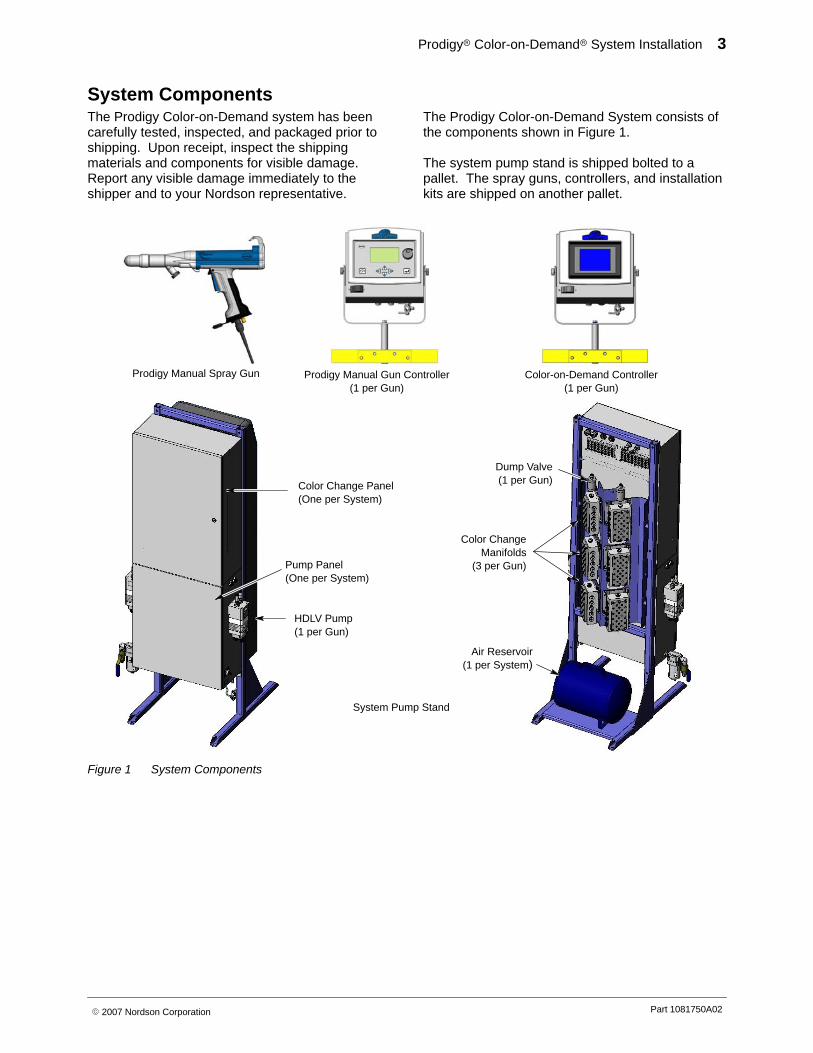
System Components The Prodigy Color-on-Demand system has beencarefully tested, inspected, and packaged prior toshipping. Upon receipt, inspect the shippingmaterials and components for visible damage.Report any visible damage immediately to theshipper and to your Nordson representative.
The Prodigy Color-on-Demand System consists ofthe components shown in Figure 1.
The system pump stand is shipped bolted to apallet. The spray guns, controllers, and installationkits are shipped on another pallet.
Prodigy Manual Spray Gun Prodigy Manual Gun Controller(1 per Gun)
Color-on-Demand Controller(1 per Gun)
Color Change Panel(One per System)
HDLV Pump(1 per Gun)
Pump Panel(One per System)
Air Reservoir(1 per System)
Color ChangeManifolds
(3 per Gun)
Dump Valve(1 per Gun)
System Pump Stand
Figure 1 System Components
Prodigy� Color-on-Demand� System Installation4
Part 1081750A02 � 2007 Nordson Corporation
Installation
WARNING: Allow only qualified personnel to perform the following tasks. Follow the safetyinstructions in this document and all other related documentation.
Specifications
Electrical 100-240 V, 50/60 Hz, 275 VA max. 1 PH
Air Input Max 6.2-7.6 bar (90-110 psi)
Weight * 125 kg (275 lbs)
Remote Control Input 24 V, 25 mA max
* Weight of stand with control panels, color change manifolds, cover, and accumulator tank mounted.
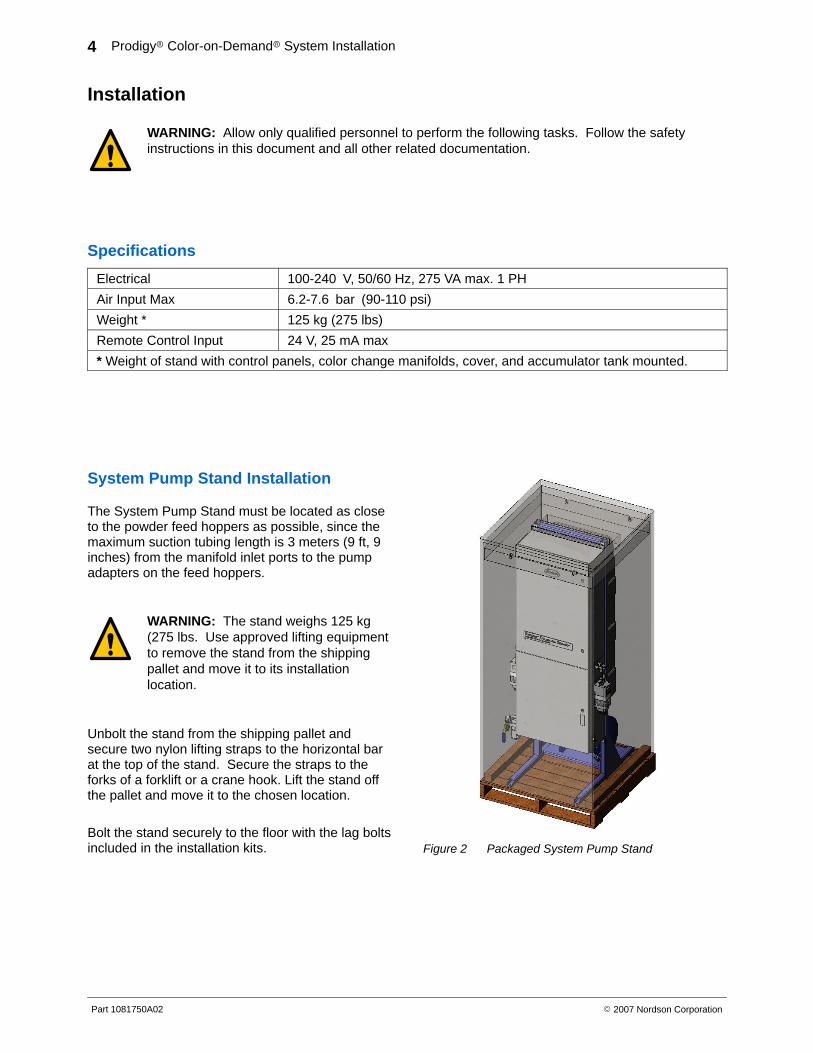
System Pump Stand Installation
The System Pump Stand must be located as closeto the powder feed hoppers as possible, since themaximum suction tubing length is 3 meters (9 ft, 9inches) from the manifold inlet ports to the pumpadapters on the feed hoppers.
WARNING: The stand weighs 125 kg(275 lbs. Use approved lifting equipmentto remove the stand from the shippingpallet and move it to its installationlocation.
Unbolt the stand from the shipping pallet andsecure two nylon lifting straps to the horizontal barat the top of the stand. Secure the straps to theforks of a forklift or a crane hook. Lift the stand offthe pallet and move it to the chosen location.
Bolt the stand securely to the floor with the lag boltsincluded in the installation kits. Figure 2 Packaged System Pump Stand
Prodigy� Color-on-Demand� System Installation 5
Part 1081750A02� 2007 Nordson Corporation
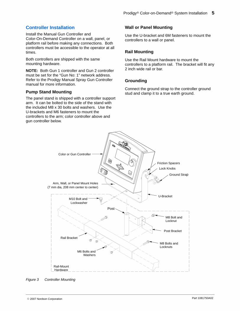
Controller Installation Install the Manual Gun Controller andColor-On-Demand Controller on a wall, panel, orplatform rail before making any connections. Bothcontrollers must be accessible to the operator at alltimes.
Both controllers are shipped with the samemounting hardware.
NOTE: Both Gun 1 controller and Gun 2 controllermust be set for the “Gun No: 1” network address.Refer to the Prodigy Manual Spray Gun Controllermanual for more information.
Pump Stand Mounting The panel stand is shipped with a controller supportarm. It can be bolted to the side of the stand withthe included M8 x 30 bolts and washers. Use theU-brackets and M6 fasteners to mount thecontrollers to the arm; color controller above andgun controller below.
Wall or Panel Mounting
Use the U-bracket and 6M fasteners to mount thecontrollers to a wall or panel.
Rail Mounting
Use the Rail Mount hardware to mount thecontrollers to a platform rail. The bracket will fit any2 inch wide rail or bar.
Grounding
Connect the ground strap to the controller groundstud and clamp it to a true earth ground.
Color or Gun Controller
U-Bracket
Lock Knobs
Ground Strap
Arm, Wall, or Panel Mount Holes(7 mm dia, 208 mm center to center)
M10 Bolt andLockwasher
Post
Rail Bracket
M6 Bolts andWashers
M8 Bolts andLocknuts
Post Bracket
M8 Bolt andLocknut
Rail-MountHardware
Friction Spacers
Figure 3 Controller Mounting
Prodigy� Color-on-Demand� System Installation6
Part 1081750A02 � 2007 Nordson Corporation
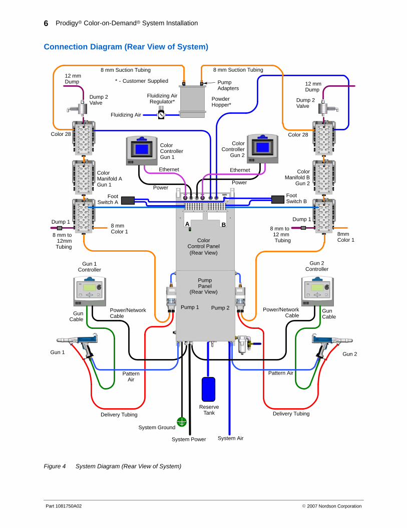
Connection Diagram (Rear View of System)
Pump 1 Pump 2
Gun 1 Gun 2
Gun 1Controller
Gun 2Controller
Fluidizing AirRegulator*
Fluidizing Air
PumpAdapters
System Air
* - Customer Supplied
System Power
PumpPanel
12 mmDump
8 mm to12mmTubing
Ethernet Ethernet
PowerPower
FootSwitch B
12 mmDump
8 mm to 12 mm Tubing
Dump 2Valve
ColorManifold B
Gun 2
Color Manifold AGun 1
ColorController
Gun 2
ColorControllerGun 1
ColorControl Panel
Color 28Color 28
8mm Color 1
8 mmColor 1
Power/NetworkCable
Power/NetworkCable
Pattern AirPatternAir
Delivery TubingDelivery Tubing
GunCable
GunCable
PowderHopper*
8 mm Suction Tubing 8 mm Suction Tubing
FootSwitch A
Dump 1Dump 1
System Ground
(Rear View)
(Rear View)
ReserveTank
A B
Dump 2Valve
Figure 4 System Diagram (Rear View of System)

Prodigy� Color-on-Demand� System Installation 7
Part 1081750A02� 2007 Nordson Corporation
System Power, Ground, and GunController Connections
Manual Gun Controller #2 Manual Gun Controller #1
Pump Panel(Bottom View)
INPUT POWER100-240 VAC 50/60 Hz 1∅ 275 VA MAX
15 Amp Breaker Max
15 m (50 ft)Network/Power Cable
6 m (20 ft)Gun Cable
15 m (50 ft)Network/Power Cable
6 m (20 ft)Gun Cable
Brown: L1 (hot)
Blue: L2 (neutral)
Green/Yellow: GND
NET/PWR
NET/PWR
1
System Ground
Ground to Booth Base
Ground to Booth Base
NET/PWR
NET/PWR
2
GUN
Optional Gun Cable Extensions4 meter: 10730276 meter: 1083912
GUN
Figure 5 System Power, Ground, and Gun Controller Connections
Prodigy� Color-on-Demand� System Installation8
Part 1081750A02 � 2007 Nordson Corporation
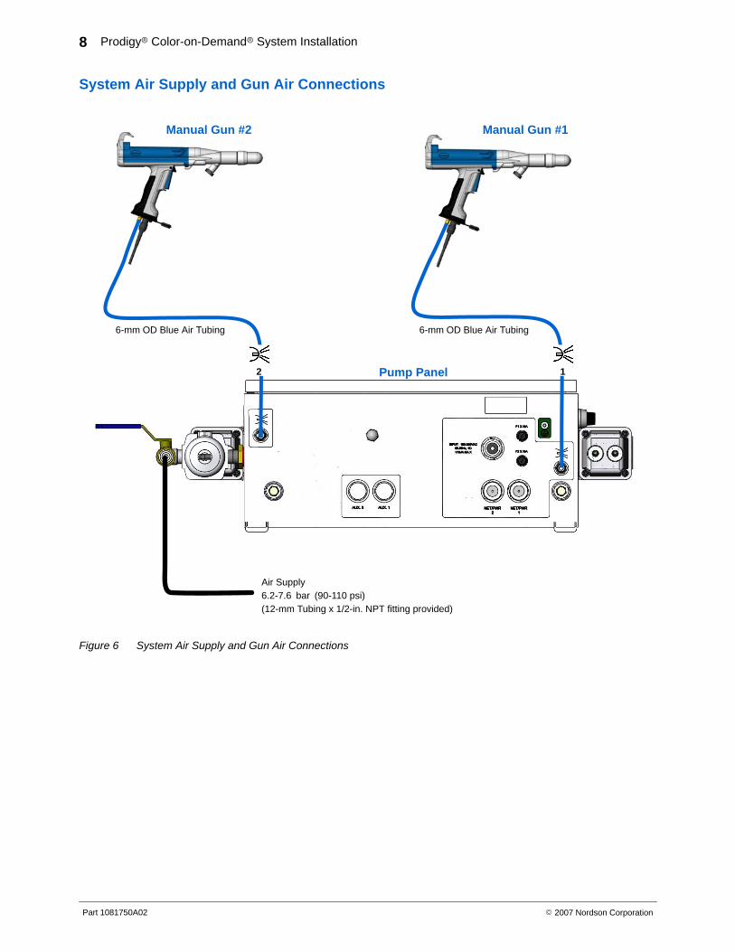
System Air Supply and Gun Air Connections
Manual Gun #2
Pump Panel
6-mm OD Blue Air Tubing
Manual Gun #1
6-mm OD Blue Air Tubing
Air Supply6.2-7.6 bar (90-110 psi)(12-mm Tubing x 1/2-in. NPT fitting provided)
12
Figure 6 System Air Supply and Gun Air Connections
Prodigy� Color-on-Demand� System Installation 9
Part 1081750A02� 2007 Nordson Corporation
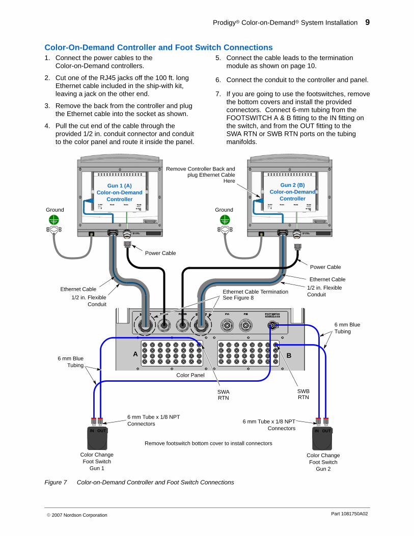
Color-On-Demand Controller and Foot Switch Connections 1. Connect the power cables to the
Color-on-Demand controllers.
2. Cut one of the RJ45 jacks off the 100 ft. longEthernet cable included in the ship-with kit,leaving a jack on the other end.
3. Remove the back from the controller and plugthe Ethernet cable into the socket as shown.
4. Pull the cut end of the cable through theprovided 1/2 in. conduit connector and conduitto the color panel and route it inside the panel.
5. Connect the cable leads to the terminationmodule as shown on page 10.
6. Connect the conduit to the controller and panel.
7. If you are going to use the footswitches, removethe bottom covers and install the providedconnectors. Connect 6-mm tubing from theFOOTSWITCH A & B fitting to the IN fitting onthe switch, and from the OUT fitting to the SWA RTN or SWB RTN ports on the tubingmanifolds.
Gun 1 (A)Color-on-Demand
Controller
Gun 2 (B)Color-on-Demand
Controller
1/2 in. FlexibleConduit
Ethernet Cable
Remove Controller Back andplug Ethernet Cable
Here
Power Cable
Color ChangeFoot Switch
Gun 1
Color ChangeFoot Switch
Gun 2
6 mm Tube x 1/8 NPTConnectors 6 mm Tube x 1/8 NPT
Connectors
6 mm BlueTubing
SWBRTN
Power Cable
GroundGround
Ethernet Cable TerminationSee Figure 8
Remove footswitch bottom cover to install connectors
Color Panel
A B
SWARTN
IN OUT
6 mm BlueTubing
IN OUT
Ethernet Cable
1/2 in. FlexibleConduit
Figure 7 Color-on-Demand Controller and Foot Switch Connections
Prodigy� Color-on-Demand� System Installation10
Part 1081750A02 � 2007 Nordson Corporation
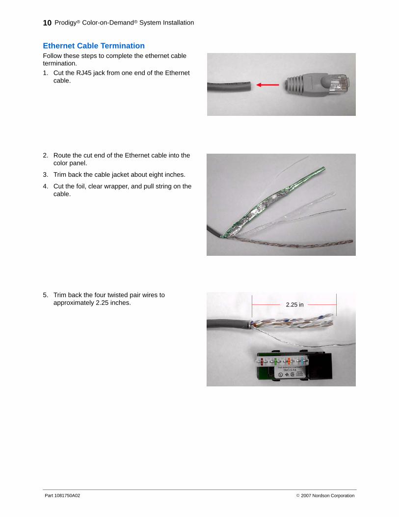
Ethernet Cable Termination Follow these steps to complete the ethernet cabletermination.
1. Cut the RJ45 jack from one end of the Ethernetcable.
2. Route the cut end of the Ethernet cable into thecolor panel.
3. Trim back the cable jacket about eight inches.
4. Cut the foil, clear wrapper, and pull string on thecable.
5. Trim back the four twisted pair wires toapproximately 2.25 inches. 2.25 in
Prodigy� Color-on-Demand� System Installation 11
Part 1081750A02� 2007 Nordson Corporation
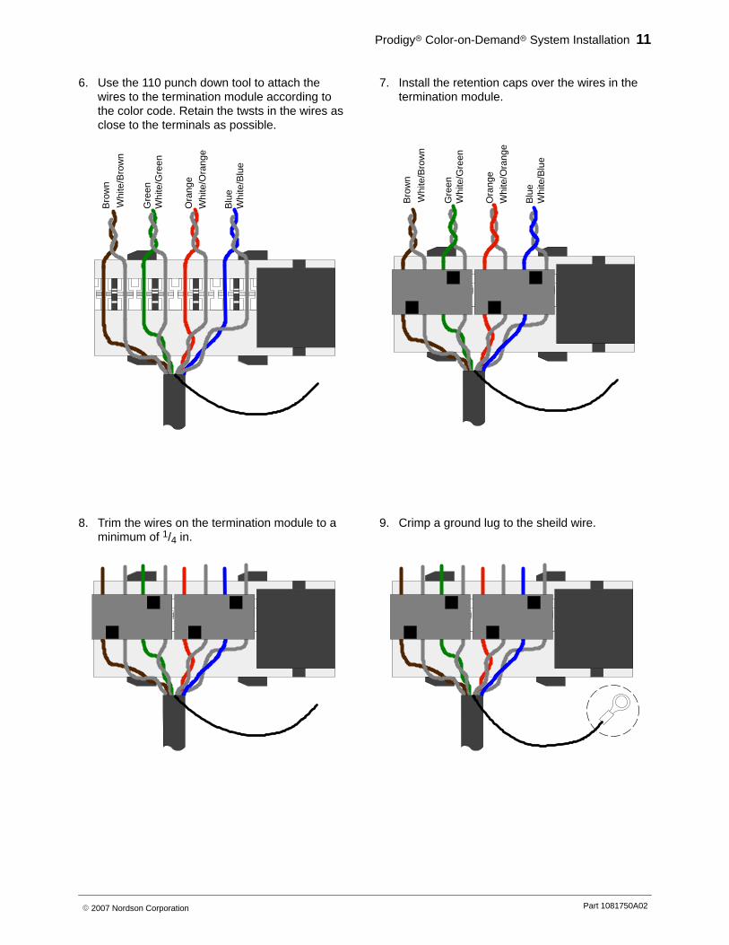
6. Use the 110 punch down tool to attach thewires to the termination module according tothe color code. Retain the twsts in the wires asclose to the terminals as possible.
Whi
te/B
row
n
Whi
te/G
reen
Whi
te/O
rang
e
Whi
te/B
lue
Bro
wn
Gre
en
Ora
nge
Blu
e
7. Install the retention caps over the wires in thetermination module.
Whi
te/B
row
n
Whi
te/G
reen
Whi
te/O
rang
e
Whi
te/B
lue
Bro
wn
Gre
en
Ora
nge
Blu
e8. Trim the wires on the termination module to a
minimum of 1/4 in.9. Crimp a ground lug to the sheild wire.
Prodigy� Color-on-Demand� System Installation12
Part 1081750A02 � 2007 Nordson Corporation
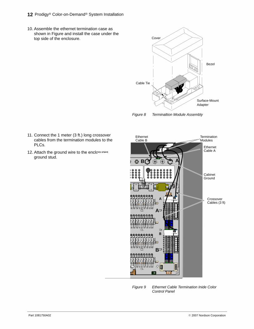
10. Assemble the ethernet termination case asshown in Figure and install the case under thetop side of the enclosure.
Bezel
Cover
Surface-MountAdapter
Cable Tie
Figure 8 Terminaltion Module Assembly
11. Connect the 1 meter (3 ft.) long crossovercables from the termination modules to thePLCs.
12. Attach the ground wire to the enclosuresground stud.
A
B
AB
Crossover Cables (3 ft)
Ethernet Cable A
Ethernet Cable B
Termination Modules
CabinetGround
Figure 9 Ethernet Cable Termination Inide ColorControl Panel
Prodigy� Color-on-Demand� System Installation 13
Part 1081750A02� 2007 Nordson Corporation
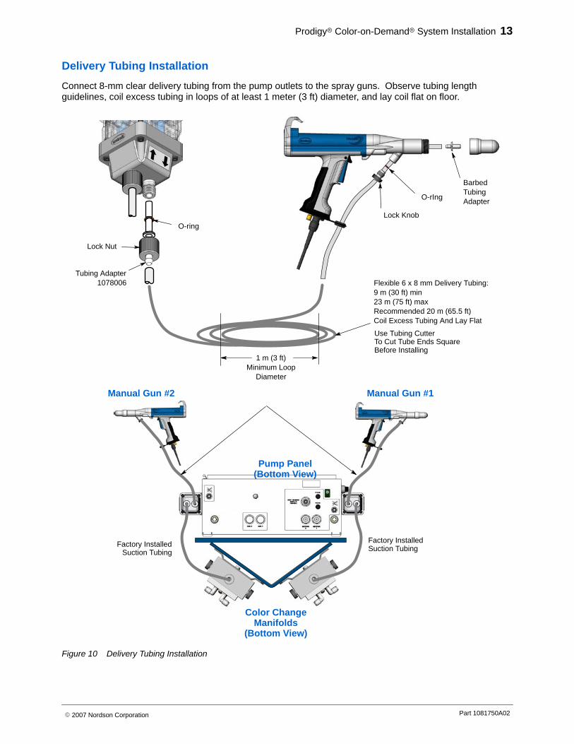
Delivery Tubing Installation
Connect 8-mm clear delivery tubing from the pump outlets to the spray guns. Observe tubing lengthguidelines, coil excess tubing in loops of at least 1 meter (3 ft) diameter, and lay coil flat on floor.
Manual Gun #2
Pump Panel(Bottom View)
Manual Gun #1
Factory InstalledSuction Tubing
Color ChangeManifolds
(Bottom View)
Factory InstalledSuction Tubing
Use Tubing CutterTo Cut Tube Ends SquareBefore Installing
Lock Knob
O-rIng
BarbedTubingAdapter
O-ring
Lock Nut
Tubing Adapter1078006
1 m (3 ft)Minimum Loop
Diameter
Flexible 6 x 8 mm Delivery Tubing:9 m (30 ft) min23 m (75 ft) maxRecommended 20 m (65.5 ft)Coil Excess Tubing And Lay Flat
Figure 10 Delivery Tubing Installation
Prodigy� Color-on-Demand� System Installation14
Part 1081750A02 � 2007 Nordson Corporation
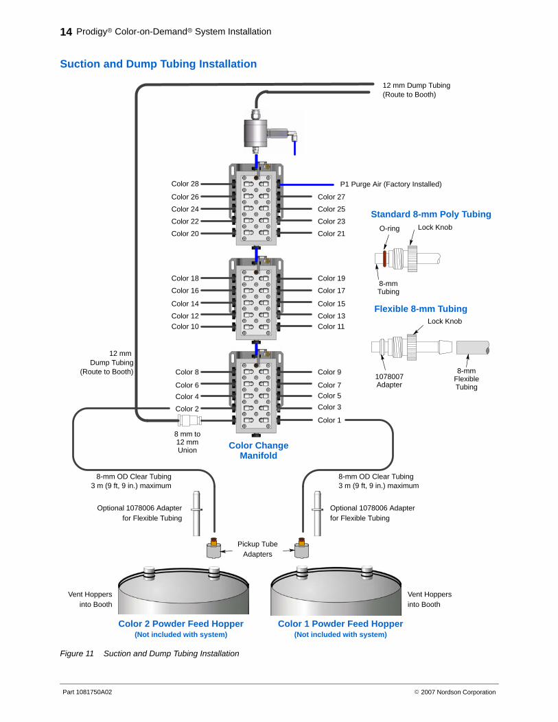
Suction and Dump Tubing Installation
8-mm OD Clear Tubing3 m (9 ft, 9 in.) maximum
Color 1 Powder Feed Hopper(Not included with system)
Color 28
12 mm Dump Tubing(Route to Booth)
12 mm Dump Tubing
(Route to Booth)
8 mm to12 mmUnion
Color 26
Color 24
Color 22
Color 20
Color 18
Color 16
Color 14
Color 12Color 10
Color 8
Color 6
Color 4
Color 2
Color 27
Color 25
Color 23
Color 21
Color 19
Color 17
Color 15
Color 13Color 11
Color 9
Color 7
Color 5
Color 3
Color 1
P1 Purge Air (Factory Installed)
Color ChangeManifold
Color 2 Powder Feed Hopper(Not included with system)
Vent Hoppersinto Booth
Vent Hoppersinto Booth
8-mm OD Clear Tubing3 m (9 ft, 9 in.) maximum
8-mmTubing
O-ring Lock Knob
Standard 8-mm Poly Tubing
1078007Adapter
Lock Knob
8-mmFlexibleTubing
Flexible 8-mm Tubing
Optional 1078006 Adapterfor Flexible Tubing
Pickup TubeAdapters
Optional 1078006 Adapterfor Flexible Tubing
Figure 11 Suction and Dump Tubing Installation
Prodigy� Color-on-Demand� System Installation 15
Part 1081750A02� 2007 Nordson Corporation
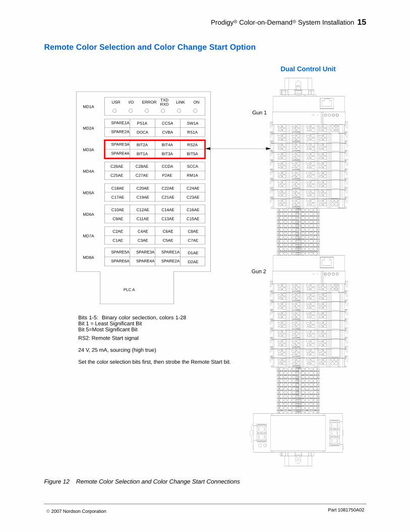
Remote Color Selection and Color Change Start Option
C24AEC18AE C20AE C22AEMD5A
D1AE
D2AE
C8AE
C7AE
C16AE
C15AE
C23AE
PLC A
C2AE
MD8A
MD7A
SPARE6A
SPARE5A
C1AE
MD6AC10AE
C9AE
C17AE
C4AE C6AE
SPARE1A
SPARE2A
C5AE
SPARE3A
SPARE4A
C3AE
C14AE
C13AE
C21AE
C12AE
C11AE
C19AE
SCCA
RM1A
RS2A
BIT5A
SW1A
RS1A
MD3A
MD4AC26AE
C25AE
SPARE4A
MD2ASPARE2A
SPARE3A
SPARE1A
CCDA
P2AE
BIT3A
C28AE
C27AE
BIT1A
BIT4A
CCSA
CVBADOCA
BIT2A
PS1A
I/OMD1A
USR TXDRXDERROR LINK ON
Bits 1-5: Binary color seclection, colors 1-28Bit 1 = Least Significant BitBit 5=Most Significant Bit
RS2: Remote Start signal
24 V, 25 mA, sourcing (high true)
Set the color selection bits first, then strobe the Remote Start bit.
Gun 1
Gun 2
Dual Control Unit
Figure 12 Remote Color Selection and Color Change Start Connections
Prodigy� Color-on-Demand� System Installation16
Part 1081750A02 � 2007 Nordson Corporation