Embed Size (px)
Citation preview

EAC FTT
MODULAR INVERTER SERIES
500W – 2000W
Users Manual
113904B – System Users Manual 10/13/2015 EMCSA00878 1
C A U T I O N
READ ENTIRE MANUAL AND REVIEW ALL DOCUMENTATION BEFORE ATTEMPTING SYSTEM INSTALLATION
FOR SERVICE OR INSTALLATION INFORMATION: TELEPHONE: (610) 868-5400 (24 HR. HOTLINE)
FAX: (610) 954-8227
FOR YOUR PROTECTION
PLEASE COMPLETE AND RETURN WARRANTY REGISTRATION CARD IMMEDIATELY.

113904B – System Users Manual 10/13/2015 EMCSA00878 2
This unit contains LETHAL VOLTAGES. All repairs and service should be performed by AUTHORIZED SERVICE PERSONNEL ONLY! There are NO USER SERVICEABLE PARTS inside this unit.
IMPORTANT SAFEGUARDS When using electrical equipment, you should always follow basic safety precautions, including the following:
1. READ AND FOLLOW ALL SAFETY INSTRUCTIONS.
2. Do not install the system outdoors. 3. Do not install near gas or electric heaters or in other high-temperature
locations. 4. Use caution when servicing batteries. Depending on battery type, batteries
contain either acid or alkali and can cause burns to skin and eyes. If battery fluid is spilled on skin or in the eyes, flush with fresh water and contact a physician immediately.
5. Equipment should be mounted in locations where unauthorized personnel
will not readily subject it to tampering. 6. The use of accessory equipment not recommended by Manufacturer may
cause an unsafe condition and void the warranty. 7. Do not use this equipment for other than its intended use. 8. Qualified service personnel must perform all servicing of this equipment.
SAVE THESE INSTRUCTIONS
The installation and use of this product must comply with all national, federal, state, municipal, or local codes that apply. If you need help, please call Service.

113904B – System Users Manual 10/13/2015 EMCSA00878 3
User’s Guide An on-site permanent log of the inspection, testing, and maintenance of the emergency electrical power supply system shall be maintained in accordance with the Manufacturer's operating manual. The log shall include: The date on which the inspection, testing, and maintenance exercise was carried out. The name of the person(s) who performed the inspection, testing, and maintenance. A note of any unsatisfactory condition observed or discovered, and the steps taken to correct the condition.

113904B – System Users Manual 10/13/2015 EMCSA00878 4
C H A P T E R 1
INTRODUCTION
Keep this manual and the System Installation Guide in the folder mounted inside the unit. This unit is a microprocessor controlled PWM (Pulse Width Modulated) pure sine wave based DC to AC power inverter utilizing MOSFET technology. It integrates a fully automatic 3-rate battery charger, a solid-state transfer system, control circuitry, self testing and recording digital meter display, and maintenance free sealed lead calcium type batteries. The system components are carefully matched to make the unit a completely self-contained, fully automatic standby power source for operation on all types of lighting loads. The batteries are sized and tested per UL-924 and Life Safety Code ANSI / NFPA 101, providing emergency power for a minimum of 90 minutes. If the duration of a power failure is greater than the batteries storage capability, the inverter will automatically shut down when the battery voltage reaches 85% of the nominal DC voltage. This feature protects the battery from being permanently damaged from a deep discharge that could cause cell reversal. This battery protection feature is called "Low Voltage Disconnect" or L.V.D. When the AC power is restored after a full discharge, the system will be ready for another power failure within 24hrs. If another power failure occurs before the 24-hour recharge time, the run time will be decreased.
The front panel display incorporates an alphanumeric 2x20 LCD character display, LED status indicators and a 4 x 4 keypad. All user interface functions are available from the front panel assembly.
Utilizing a small footprint, this unit is for use with any lighting load including quartz, HID, incandescent, fluorescent and halogen.
HOW TO USE THIS MANUAL This manual tells you how to start, operate, and communicate with your unit and lets you know how to get more information for special situations. Please record your unit’s model number, serial number, and part number below. You can find these numbers on the labels on the inside panel. Model Number __________________________ Serial Number __________________________ Part Number ___________________________

113904B – System Users Manual 10/13/2015 EMCSA00878 5
Service and Support We are committed to outstanding customer service. A service technician is available 24 hours a day, 365 days a year. Service is also available 24 hours a day to give you access to technical notes and product information. You can also visit our web site. NOTE: Please have your unit’s Serial and Model numbers available when you call; this number is located behind the left door. Contact SERVICE one of the following ways: Service Number: 610-868-5400 Service Fax: 610-954-8227

113904B – System Users Manual 10/13/2015 EMCSA00878 6
C H A P T E R 2
ENVIRONMENT Make sure the environment is a clean, cool, dry place with normal ventilation.
Storage Temperature Store the batteries (in the system or battery cabinet) at -18 to 40°C (0 to 104°F). Batteries have a longer shelf life if they are stored below 25°C (77°F). Keep stored batteries fully charged. Recharge the batteries every 90–120 days. The system or battery cabinet without batteries may be stored at -20 to 70°C (-4 to 158°F).
Ventilation The air around the unit must be clean, dust-free, and free of corrosive chemicals or other contaminants. Do not place the system or batteries in a sealed room or container.
Operating Temperature System can operate from 20° to 30°C (68° to 86°F) and up to 95% relative humidity. The batteries’ service life is longer if the operating temperature stays below 25°C (77°F).
Batteries The temperature should be near 25°C (77°F) for optimum battery performance. Batteries are less efficient at temperatures below 18°C (65°F), and high temperatures reduce battery life. Typically, at about 35°C (95°F), battery life is half of what it would be at a normal temperature of 25°C (77°F). At about 45°C (113°F), battery life is one-fourth of normal.
Make sure that heaters, sunlight, air conditioners, or outside air vents are not directed toward the batteries. These conditions can make the temperature within battery strings vary, which can cause differences in the batteries’ voltages. Eventually, these conditions affect battery performance.
If the batteries are not in the system, remember that the batteries should be installed as close as possible to the unit to reduce DC wiring costs and improve battery performance.
Do not allow tobacco smoking, sparks, or flames in the system location because hydrogen is concentrated under the vent cap of each cell of the battery. Hydrogen is highly explosive, and it is hard to detect because it is colorless, odorless, and lighter than air.
Every type of battery can produce hydrogen gas, even sealed maintenance-free batteries. The gas is vented through the vent caps and into the air, mainly when the unit is charging the batteries. The batteries produce the most hydrogen when maximum voltage is present in fully charged batteries; the batteries do not produce hydrogen during float charging. The amount of current that the charger supplies to the batteries (not the battery ampere-hour) determines how much hydrogen is produced.
High Altitude Operation The maximum operating ambient temperature drops 1°C per 300m (2°F per 1000 ft) above sea level. Maximum elevation is 3000m (10,000 ft).

113904B – System Users Manual 10/13/2015 EMCSA00878 7
C H A P T E R 3
STARTUP AND SHUTDOWN PROCEDURE Refer to the Installation Manual to secure the unit and install AC and DC wiring.
STARTUP PROCEDURE For the initial startup of the system, please fill out the blue warranty card. Failure to do so will void warranty.
CAUTION: HAZARDOUS VOLTAGES – ONLY QUALFIED SERVICE PERSONNEL SHOULD PERFORM PROCEDURE.
1. Verify that the installation switch located below the front panel is in the OFF position.
Verify that AC input is disconnected. 2. Turn on the DC Circuit Breaker CB1. 3. Energize the Mains AC input by turning on the units input circuit breaker and/or the
Distribution Panel breaker located upstream from the inverter. 4. Turn the installation switch to the On position. The Front Panel display should now
be illuminated and a slight hum should be heard from the inverter transformer. The unit is now charging and the output should be energized. Now turn on the output circuit breaker(s).
SHUTDOWN PROCEDURE 1. Interrupt the AC Mains to the machine by the Distribution Panel Breaker or the
machines input circuit breaker. The Inverter should then start. 2. Turn the installation switch located on the inverter chassis to the off position. The
inverter should stop. 3. Turn off the DC Circuit Breaker CB1.
CAUTION: HAZARDOUS VOLTAGES STILL EXIST AT THE BATTERY TERMINAL BLOCK AND WITHIN THE SYSTEM. AUTHORIZED SERVICE TECHNICIANS MUST DISCHARGE DC CAPACITORS AND TURN OFF UTILITY POWER BEFORE SERVICING EQUIPMENT.
CAUTION: DO NOT LEAVE THE SYSTEM SHUTDOWN FOR A PROLONGED LENGTH OF TIME. LEAD BASED BATTERIES WILL EXPERIENCE PERMANENT DAMAGE FROM LACK OF CHARGING AFTER A FEW MONTHS.

113904B – System Users Manual 10/13/2015 EMCSA00878 8
C H A P T E R 4
OPERATION The following is a description of the status LED's located on the front panel and the internal fan.
AC Present When the AC Mains is present, the LED will illuminate. If a power failure was long in duration, or the AC mains was disconnected by some other means (Circuit breaker open) the AC Present LED would not be illuminated. When the control circuit senses that the line has dropped below an acceptable level (Black Out, Brown Out, or Transient), the inverter will energize for at least one minute. So, if the power failure was a momentary glitch, the AC present LED would be illuminated but the inverter would be running.
System Ready When the system has adequate battery voltage to transfer, the System Ready LED will illuminate. This feature prevents damage from multiple deep discharges of the battery.
Battery Charging When the AC Mains is connected to the line and the battery is charging under normal conditions, the Battery Charging LED will illuminate.
Battery Power When the inverter is producing output power (battery is being discharged), the Battery Power LED will be illuminated.
Fault This is a summary Fault indication. When there is a fault condition present, the Fault LED will illuminate. To view which fault is present, use the keypad and LCD display feature. The front panel display will provide the user with a variety of information. It has a full compliment of Meter functions, Control functions and Program functions.
Fan
The fan operates during emergency mode and only during normal mode when the batteries are being
charged. When the batteries reach float condition (trickle charge) the fan turns off.

113904B – System Users Manual 10/13/2015 EMCSA00878 9
C H A P T E R 5
FRONT PANEL DISPLAY The Front panel consists of a 2 x 20 alphanumeric LCD display with LED Back lighting, 5 Status LED indicators and a 4 x 4 keypad for user interface.
Figure 5.1 Front Panel Display

113904B – System Users Manual 10/13/2015 EMCSA00878 10
Control Panel Keypads
Table 5.1 Keypad Functions
Key Name Description
Meter (Blue) Pressing this key will activate Meter Functions
Control (Red) Pressing this key will activate Control Functions
Program (Black) Using this key, you can enter passwords or change parameter values. To enter passwords, press [PROGRAM], enter the password, and press [ENTER]. NOTE: A password must be entered to change parameters.
Enter (Grey) This key records or enters a task you perform using the control panel keys.
[ ◄ ] This key functions as Left scroll key
[ ► ] This key functions as Right scroll key
[ 0 ] This key works as a number key; it is also used to display active alarms when in CONTROL Mode.
[ 1 ] through [ 9 ] These keys work as number keys.
Meter Functions
Meter functions are available by pressing the METER keypad to get to the Meter Menu and then pressing the desired function keypad. (See figure 5.1)
Table 5.2 Meter Functions
Function Description Keypad Text
Voltage Input Measures the AC Input Voltage to the Inverter V IN
Voltage Output Measures the AC Output Voltage from the Inverter V OUT
Current Output Measures the AC Output Current from the Inverter. If optional Normally Off loads are connected, it will read the sum of Normally On and Normally Off outputs.
I OUT
Battery Voltage Measures Battery Voltage V BATT
Battery Current Measures the Battery Current. When in charge mode, the current will be positive. When in Inverter mode, the current will be negative.
I BATT
VA Output Multiplication of the output voltage and output current VA OUT
Inverter Watts Multiplication of the battery voltage and the battery current INV. WATTS
Inverter Minutes Total minutes the system has run on inverter INV. MIN
Temperature Measures the ambient temperature of the electronics enclosure.
TEMP
System Days Total days the system has been in service. SYS. DAYS
113904B – System Users Manual 10/13/2015 EMCSA00878 11
Control Functions
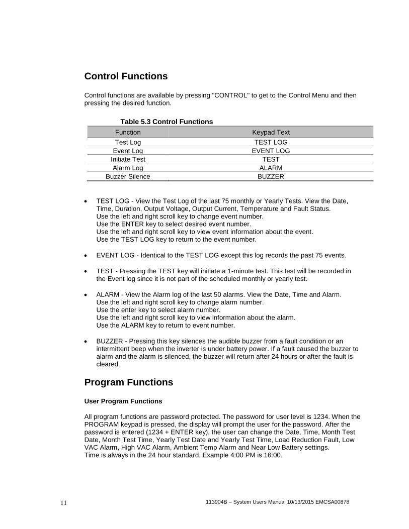
Control functions are available by pressing "CONTROL" to get to the Control Menu and then pressing the desired function.
Table 5.3 Control Functions
Function Keypad Text
Test Log TEST LOG
Event Log EVENT LOG
Initiate Test TEST
Alarm Log ALARM
Buzzer Silence BUZZER
TEST LOG - View the Test Log of the last 75 monthly or Yearly Tests. View the Date, Time, Duration, Output Voltage, Output Current, Temperature and Fault Status. Use the left and right scroll key to change event number. Use the ENTER key to select desired event number. Use the left and right scroll key to view event information about the event. Use the TEST LOG key to return to the event number.
EVENT LOG - Identical to the TEST LOG except this log records the past 75 events.
TEST - Pressing the TEST key will initiate a 1-minute test. This test will be recorded in the Event log since it is not part of the scheduled monthly or yearly test.
ALARM - View the Alarm log of the last 50 alarms. View the Date, Time and Alarm. Use the left and right scroll key to change alarm number. Use the enter key to select alarm number. Use the left and right scroll key to view information about the alarm. Use the ALARM key to return to event number.
BUZZER - Pressing this key silences the audible buzzer from a fault condition or an intermittent beep when the inverter is under battery power. If a fault caused the buzzer to alarm and the alarm is silenced, the buzzer will return after 24 hours or after the fault is cleared.
Program Functions
User Program Functions
All program functions are password protected. The password for user level is 1234. When the PROGRAM keypad is pressed, the display will prompt the user for the password. After the password is entered (1234 + ENTER key), the user can change the Date, Time, Month Test Date, Month Test Time, Yearly Test Date and Yearly Test Time, Load Reduction Fault, Low VAC Alarm, High VAC Alarm, Ambient Temp Alarm and Near Low Battery settings. Time is always in the 24 hour standard. Example 4:00 PM is 16:00.

113904B – System Users Manual 10/13/2015 EMCSA00878 12
Table 5.4 Program Functions
Parameter Format Factory Default
Date MM/DD/YY (Month, Date, Year) Current Date
Time HH/MM (Hours, Minutes) Eastern Stand Time
Monthly Test Date DD (Date) 15th of the Month
Monthly Test Time HH/MM (Hours, Minutes) 5:00
Yearly Test Date MM (Month) 01
Yearly Test Time HH/MM (Hours, Minutes) 8:00
Load Reduction AAAA(Amps) 0.0A
Low VAC Alarm VVVV(Volts) 1.0V
High VAC Alarm VVVV(Volts) 999.9V
Ambient Temp Alarm DDD(Degrees Centigrade) 70°C
Near Low Battery VVVV(Volts) 43VDC
Near Low Battery Voltage is in VVVV (Volts). The last digit entered is after the decimal place. I.E. (430 + ENTER) will register 43.0VDC.
Load Reduction Fault is in AAAA (Amps). The last digit entered is after the decimal place. I.E. (480 + ENTER) will register 48.0 Amps. If the output current under battery power is 10 percent below this number, the alarm will be set.
Low AC Voltage Alarm is in VVVV (Volts). The last digit entered is after the decimal place. I.E. (1200 + ENTER) will register 120.0 Volts. If the Input AC Voltage goes below this number the alarm will be set.
High AC Voltage Alarm is similar to Low AC Voltage Alarm.
Ambient Temperature Alarm is in DDD (Degrees Centigrade). I.E. (75 + ENTER) will register 75 deg. C. When the ambient temperature internal to the inverter enclosure goes above the set point the alarm will be set.

113904B – System Users Manual 10/13/2015 EMCSA00878 13
C H A P T E R 6
SPECIFICATIONS
General Specifications
Input Voltage 120 or 277Vac 1-phase 2-wire +10% -15%. Contact factory for all other voltages.
Input Power Walk-in Limiting inrush current to less than 125%, 10 times for 1 line cycle
Input Frequency 60Hz, +/- 3%, 50Hz Available upon request
Synchronizing Slew Rate 1Hz per second nominal
Protection Input Circuit Breaker
Harmonic Distortion < 10%
Power Factor .5 lag/lead
Output Voltage 120 or 277Vac 1-phase 2-wire. Contact factory for all other voltages.
Static Voltage Load current change +/-2%, battery discharge +/-12.5%
Dynamic Voltage +/- 2% for +/-25% load step change, +/-3% for a 50% load step change, recovery within 3 cycles
Harmonic Distortion < 3% THD for linear load
Overload Fuse protected
Output Frequency 60Hz +/- .05Hz during emergency mode
Load Power Factor .5 lag to .5 lead
Inverter Overload 125% for 5 minutes
Protection Circuit Breaker
Battery Type Valve-regulated sealed lead-calcium.
Charger Microprocessor controlled for various battery types and temperature compensating (recharge per UL924 spec)
Protection Automatic low-battery disconnect; automatic restart upon utility return.
Disconnect Circuit Breaker & Fuse
Optional Runtimes Extended runtimes available. Consult factory for additional information.
Environmental Altitude < 10,000 feet (above sea level) without derating
Operating Temperature 20 to 30 degree Celsius
Storage Temperature -20 to 70 degrees Celsius (electronics only)
Relative Humidity < 95% (non-condensing)
General Design Stand-By UPS System. PWM inverter type utilizing MOSFET technology with 2mS transfer time.
Generator Input Compatible with generators.
Control Panel Microprocessor controlled 2 x 20-charactor Display with touch pad controls & functions
5 LED indicators & alarm with ring-back feature
Metering Input & Output Voltage, Battery Voltage, Battery & Output Current, Output VA, Temperature, Inverter Wattage
Alarms High/Low Battery Charger Fault, Near Low Battery, Low Battery, Load Reduction Fault, Output Overload,
High/Low AC Input Volts, High Ambient Temperature, Inverter Fault, Output Fault, Optional Circuit Breaker Trip
Communications Optional RS-232 port (DB9)
Manual Maintenance Bypass Optional external without internal distribution breakers.
Alarm Contacts Optional Summary Form "C" Contacts
Warranty 1 year standard warranty includes all parts, labor, & travel expenses within 48 contiguous states. Up to 10 years
prorated warranty on batteries. Extended warranties, preventative maintenance and customized service plans
are available.
Factory Start-up Purchase factory start-up & receive 1 additional year of warranty.
5 Year Service Plan Purchase 5 year service plan & receive free factory start-up.
Physical Cabinet Freestanding NEMA Type 1
Cooling Forced Air, during emergency mode.
Cable Entry Left-Side
Access Front

113904B – System Users Manual 10/13/2015 EMCSA00878 14
C H A P T E R 7
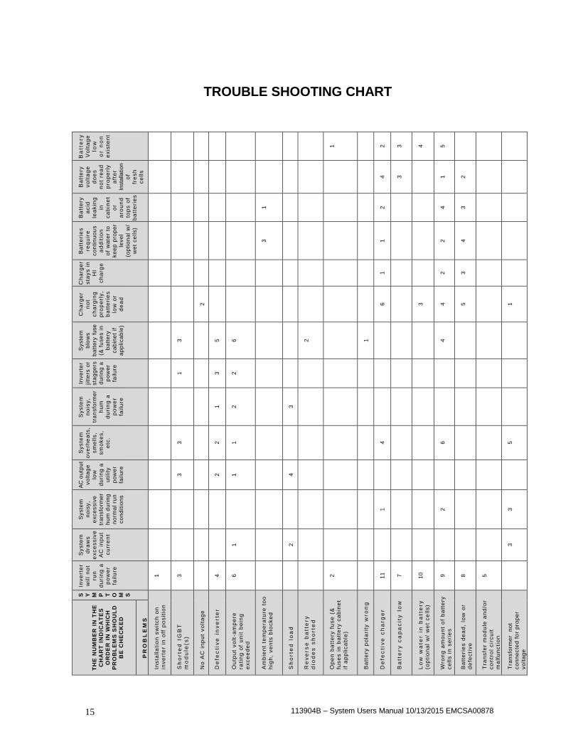
MAINTENANCE AND SERVICE The Self-testing feature of the inverter ensures that the system is tested at least once per month for 5 minutes and once per year for 90 minutes. If there are any problems with the self-tests, the fault log shall indicate which faults occurred. Please see the fault descriptions and troubleshooting guide. A few simple maintenance operations performed periodically will help ensure many years of trouble free operation. Battery terminals should be checked for tightness and corrosion. If severe corrosion is evident, maintenance is required to correct this situation. Since the unit depends on unrestricted airflow for cooling of power handling components, it is important to keep the air vents free of any obstruction. If the environment tends to be extremely dusty, occasionally blow away any accumulation of dust on components. Please follow the shutdown procedure before cleaning. CAUTION: Follow the shutdown procedure (See Chapter 3) before cleaning. An authorized technician only should perform Service!
Table 7.1 Preventive Maintenance Schedule
SERVICE TO PERFORM: PERFORM SERVICE EVERY:
3 MONTHS 6 MONTHS 12 MONTHS
1. TEST UNIT: NOTE: Perform manual test only when critical load is connected but not required. ----- Output voltage should be present. ----- Confirm operations of front panel indicators.
X
2. INSPECT BATTERIES: ----- All connections are tight. ----- Connections have no corrosion. (Clean if necessary).
X
CLEAN UNIT: NOTE: Unit must be shut down
during this service. ----- Inspect air vents and clean if necessary. ----- Clean excessive dust from inside cabinet(s). ----- Clean excessive dust from fan(s).
X
"X" Indicates when to perform service. Lines below the "X" are for the date of service.
113904B – System Users Manual 10/13/2015 EMCSA00878 15
TROUBLE SHOOTING CHART
Ba
tte
ry
Vo
lta
ge
low
or n
on
ex
iste
nt
1 2
3
4
5
Ba
tte
ry
vo
lta
ge
do
es
no
t re
ad
pro
pe
rly
aft
er
Insta
llatio
n
of
fre
sh
ce
lls
4
3 1
2
Ba
tte
ry
ac
id
lea
kin
g
in
ca
bin
et
or
aro
un
d
top
s o
f
ba
tte
rie
s
1 2 4
3
Ba
tte
rie
s
req
uir
e
co
nti
nu
ou
s
ad
dit
ion
of
wa
ter
to
ke
ep
pro
pe
r
lev
el
(op
tio
na
l w
/
we
t c
ells)
3 1 2
4
Ch
arg
er
sta
ys
in
HI
ch
arg
e
1 2
3
Ch
arg
er
no
t
ch
arg
ing
pro
pe
rly
,
ba
tte
rie
s
low
or
de
ad
2 6 3
4
5 1
Sy
ste
m
blo
ws
ba
tte
ry f
use
(& f
use
s i
n
ba
tte
ry
ca
bin
et
if
ap
plica
ble
)
3 5
6 2 1 4
Inv
ert
er
jitt
ers
or
sta
gg
ers
du
rin
g a
po
we
r
failu
re
1 3
2
Sy
ste
m
no
isy
,
tra
nsfo
rme
r
hu
m
du
rin
g a
po
we
r
fail
ure
1
2 3
Sy
ste
m
ov
erh
ea
ts,
sm
ell
s,
sm
ok
es
,
etc
.
3 2 1 4 6 5
AC
ou
tpu
t
vo
lta
ge
low
du
rin
g a
uti
lity
po
we
r
failu
re
3 2
1 4
Sy
ste
m
no
isy
,
exc
es
siv
e
tra
nsfo
rme
r
hu
m d
uri
ng
no
rma
l ru
n
co
nd
itio
ns
1 2 3
Sy
ste
m
dra
ws
ex
ce
ss
ive
AC
in
pu
t
cu
rre
nt
1 2 3
Inv
ert
er
wil
l n
ot
run
du
rin
g a
po
we
r
fail
ure
1
3 4
6 2
11
7
10
9
8
5
S
Y
M
P
T
O
M
S
Ins
tall
ati
on
sw
itc
h o
n
inv
ert
er
in o
ff p
os
itio
n
Sh
orte
d I
GB
T
mo
du
le(s
)
No
AC
in
pu
t v
olt
ag
e
De
fec
tiv
e i
nv
erte
r
Ou
tpu
t v
olt
-am
pe
re
rati
ng
of
un
it b
ein
g
ex
ce
ed
ed
Am
bie
nt
tem
pe
ratu
re t
oo
hig
h,
ve
nts
blo
ck
ed
Sh
orte
d l
oa
d
Re
ve
rs
e b
att
ery
dio
de
s s
ho
rte
d
Op
en
ba
tte
ry f
us
e (
&
fus
es
in
ba
tte
ry c
ab
ine
t
if a
pp
lic
ab
le)
Ba
tte
ry p
ola
rity
wro
ng
De
fec
tiv
e c
ha
rg
er
Ba
tte
ry
ca
pa
cit
y l
ow
Lo
w w
ate
r i
n b
att
ery
(op
tio
na
l w
/ w
et
ce
lls
)
Wro
ng
am
ou
nt
of
ba
tte
ry
ce
lls
in
se
rie
s
Ba
tte
rie
s d
ea
d,
low
or
de
fec
tiv
e
Tra
ns
fer
mo
du
le a
nd
/or
co
ntr
ol
cir
cu
it
ma
lfu
nc
tio
n
Tra
ns
form
er
no
t
co
nn
ec
ted
fo
r p
rop
er
vo
lta
ge
TH
E N
UM
BE
R I
N T
HE
CH
AR
T I
ND
ICA
TE
S
OR
DE
R I
N W
HIC
H
PR
OB
LE
MS
SH
OU
LD
BE
CH
EC
KE
D
PR
OB
LE
MS

113904B – System Users Manual 10/13/2015 EMCSA00878 16
RETURN MATERIAL AUTHORIZATION (RMA) POLICY No return material is accepted without written "Return Material Authorization"(RMA). An RMA number is obtainable by contacting the Field Service Department. Every effort will be made to correct problems over the phone before a RMA is granted or a service trip made. Cooperation will save both time and expense for customer and manufacturer. If it is deemed necessary to return material, the RMA number must appear on shipping labels, packing slips, and bills of lading.
OUT OF WARRANTY REPAIR CHARGES AND LABOR Contact Field service for current parts and labor rates. A minimum rate will be assessed. The manufacturer will not proceed with repairs of an out of warranty unit until authorization in the form of a purchase order is received from the customer. The unit for repair must be returned prepaid with an RMA number on the carton. For travel to the job site, a quote "Not to Exceed" estimate will be given. A purchase order to cover that amount is required before a trip to the job site is made.

113904B – System Users Manual 10/13/2015 EMCSA00878 17
LIMITED WARRANTY The parts and on-site labor for the electronics portion of this equipment are warranted against defects in workmanship and material for a period of one year from time of shipment, but in no case will this warranty be valid if installation of equipment is not accomplished within 180 days from date of shipment. Batteries cannot be disconnected from the unit for long periods (180 days) or they will not be able to charge, creating malfunction of both batteries and/or electronics and thereby voiding the warranty. Systems ordered with "Heavy Lead" batteries over 25 Ah have a one year unconditional battery warranty with an additional prorated warranty contingent upon timely return of warranty registration card and the terms called out in the particular battery warranty sheet. See individual battery warranty policy.
The warranty does not cover damage caused by abuse, improper environmental conditions, shipping damage, improper electronics and/or battery installation, unauthorized modifications, service by unauthorized personnel, transportation of damaged equipment, or acts of war. Damage due to lack of maintenance (where applicable) or damage resulting from installation in areas with other than normal temperatures are not covered. See the battery warranty policy for details, as adverse environmental conditions reduce battery life and void the warranty. Replacement of fuses, pilot lamps, and/or contractor labor is not included in warranty. Damage do to acts of nature, such as, but not limited to, lightning, flooding, explosions and earthquakes, are not covered. The warranty is limited to the repair and/or replacement of parts and/or units that upon examination at our factory and/or job site are determined to be defective and in our judgment are subject to repair or replacement. All such repair shall be manufacturer's exclusive remedy. A date code, part number and serial number identify all such units.
TO THE EXTENT ALLOWED BY LAW, MANUFACTURER DISCLAIMS ALL OTHER WARRANTIES, EXPRESS OR IMPLIED, INCLUDING, BUT NOT LIMITED TO, AND LEED WARRANTIES OR MERCHANT ABILITY OR FITNESS FOR A PARTICULAR PURPOSE, AND ANY IMPLIED WARRANTY OF MERCHANT ABILITY OR FITNESS FOR A PARTICULAR PURPOSE ON PRODUCT IS LIMITED IN DURATION TO THE DURATION OF THIS WARRANTY. TO THE EXTENT ALLOWED BY LAW, THE MANUFACTURER SHALL NOT BE LIABLE FOR ANY SPECIAL, INCIDENTAL, OR CONSEQUENTIAL DAMAGES INCLUDING, BUT NOT LIMITED TO, LOSS OF PROFITS, INJURIES TO PROPERTY, LOSS OF USE OF THE PRODUCT OR ANY ASSOCIATED EQUIPMENT. Special on site extended warranties are also available upon request. The warranty period may be adjusted because of special circumstances, but only by arrangement with the manufacturer at the time of purchase. All in or out of warranty repaired material or replacement units/parts carry a 90-day new part guarantee. Return of your original repaired component or unit is not guaranteed. This limited warranty is for the 48 contiguous states. For international warranty information, call the Field Service Department. See telephone number in front of manual. The standard warranty can be extended and renewed for a nominal fee. Please contact the factory for pricing information.


![4” Evo - Acuity Brandsantiquestreetlamps.acuitybrands.com/.../document/evo-lw-4_pdf.pdf · On/Off nPODM [color] Small motion 360°, ceiling (PIR / dual tech) nCM 9 / nCM PDT 9](https://img.pdfslide.net/doc/110x75/5b069b237f8b9ae9628d4cbd/4-evo-acuity-bran-npodm-color-small-motion-360-ceiling-pir-dual-tech.jpg)