Embed Size (px)
Citation preview
Product catalogIndustrial hydraulics
Part 10: ATEX units for potentially explosive atmospheres

Product catalog Industrial hydraulics
Part 10: ATEX units for potentially explosive atmospheres
RE 00112-10, Edition: 2013-12, Bosch Rexroth AG
Product catalogs Industrial hydraulics of Bosch Rexroth at a glance:
Part 1: Pumps RE 00112-01
Part 2 Motors RE 00112-02
Part 3: Cylinders RE 00112-03
Part 4: On/off valves RE 00112-04
Part 5: Proportional servo valves RE 00112-05
Part 6: Electronics RE 00112-06
Part 7: Systems RE 00112-07
Part 8: Power units, Manifolds and plates, Accumulators RE 00112-08
Part 9: Filters RE 00112-09
Part 10: ATEX units for potentially explosive atmospheres RE 00112-10
For the latest product information from Bosch Rexroth, please visit our website: www.boschrexroth.com/ics
1
Bosch Rexroth AG, RE 00112-10, Edition: 2013-12
Publisher Bosch Rexroth AGZum Eisengießer 197816 Lohr, GermanyPhone +49(0)9352/18-0Fax +49(0)9352/[email protected]
Catalog No. Document no.: RE 00112-10Material no.: R999000311Edition: 2013-12Replaces: RE 00112-07_2008-11
Reprints and translation, in whole or in part, only with the publisher´s prior consent.
Subject to revision.
Should you have queries with regard to the products in this catalog, please contact the Rexroth sales partner in your vicinity.
www.boschrexroth.com/contact
2
Contents | Explosion protection
RE 00112-10, Edition: 2013-12, Bosch Rexroth AG
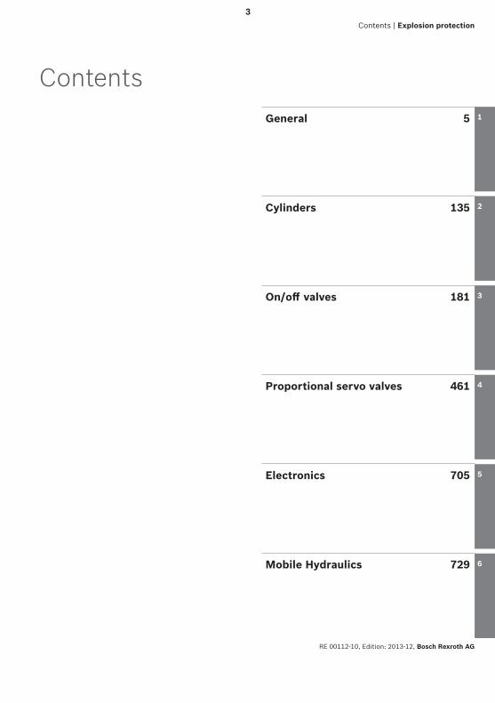
ContentsGeneral 5
Cylinders 135
On/off valves 181
Proportional servo valves 461
Electronics 705
Mobile Hydraulics 729
1
2
3
4
5
6
3

Bosch Rexroth AG, RE 00112-10, Edition: 2013-12
4
Designation Data sheet Page
General
RE 00112-10, Edition: 2013-12, Bosch Rexroth AG
Contents | General | Explosion protection
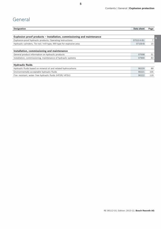
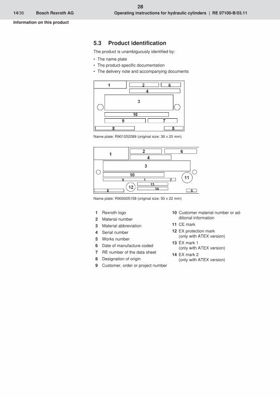
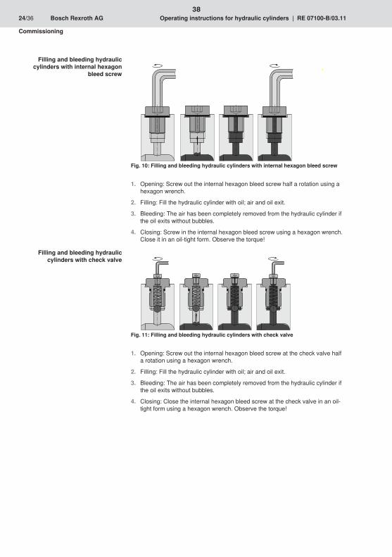
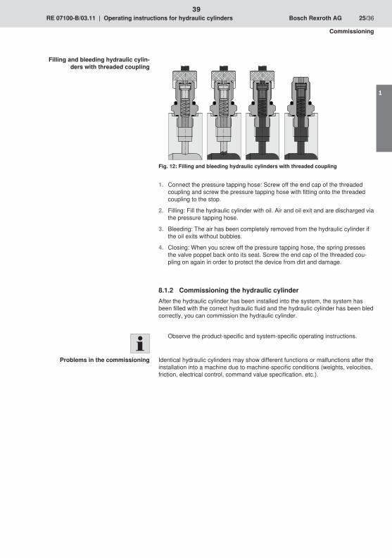
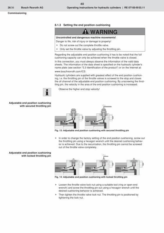
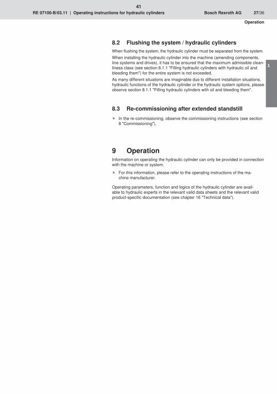
Explosion proof products – Installation, commissioning and maintenanceExplosion-proof hydraulic products, Operating Instructions 07010-X-B1 7Hydraulic cylinders, Tie rod / mill type, Mill type for explosive area 07100-B 15
Installation, commissioning and maintenanceGeneral product information on hydraulic products 07008 51Installation, commissioning, maintenance of hydraulic systems 07900 83
Hydraulic fl uidsHydraulic fl uids based on mineral oil and related hydrocarbons 90220 89Environmentally acceptable hydraulic fl uids 90221 105Fire- resistant, water- free hydraulic fl uids (HFDR/ HFDU) 90222 119
1
2
3
4
5
6
5

Bosch Rexroth AG, RE 00112-10, Edition: 2013-12
6

7
8
9
1
10
11
1
12
13
1
14
15
16
17
1
18
19
1
20
21
1
22

23
1
24
25
1
26
27
1
28
29
1
S
S
30
31
1
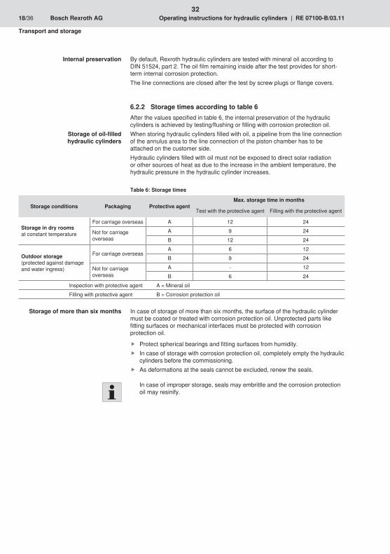
32

33
1
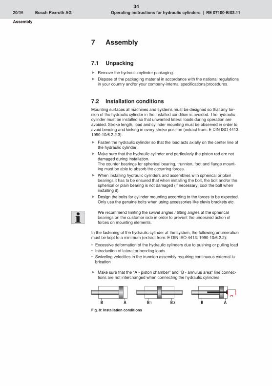
AB B2B1 AB
34
35
1
36

37
1
38
39
1
40
41
1
42

43
1
44
45
1

46

47
1
48

49
1

50
1/32RE 07008/02.05General product information on hydraulic products
1/32
DE Ihre Sprache? – Siehe Rückseite!EN Your language? – See back page!FR Votre langue ? – Voir au dos !IT La vostra lingua? – Vedi retro!FI Kohdekielet? – Katso takankatta!ES ¿Su idioma? – ¡Vea al dorso!NL Uw taal? – Zie achterzijde!SV Ditt sprak? – Se omslagets baksida!PT O seu idioma? – Consulte a contracapa!DA Dit sprog? – Se bagside!EL Η γλώσσα σαρ; – Βλέπε πίσω πλευρά!
51

2/32 Bosch Rexroth AG Hydraulics General product information RE 07008
Contents Page
1 Important basic information 4
1.1 Conventions used in this product information 4
1.2 What you need to know about this product information 4
1.3 The contents of this product information 4
2 Scope of delivery and responsibilities 5
2.1 Scope of delivery and responsibilities of Bosch Rexroth 5
2.2 Responsibilities of the plant operator 5
2.3 Liability, guarantee, warranty 6
2.4 Copyright 6
3 Important basic safety instructions 7
3.1 What to do in an emergency 7
3.2 Safety labelling on the hydraulic product 7
3.3 Proper use 7
3.4 Requirements for personnel, duty of care 8
3.5 General ancillary dangers and protective measureswhen operating hydraulic products 9
4 Technical data and ambient conditions 11
4.1 Information about pressure fl uids 11
4.2 Ambient conditions 11
5 What you need to know about pressure fl uids 13
5.1 How to handle pressure fl uids safely 13
5.2 Functions and effectiveness 13
5.3 Viscosity 13
5.4 Leakage fl uid 14
5.5 Topping up/refi lling 14
6 Construction and mode of operation of a hydraulic system 15
6.1 Defi nitions of terms 15
6.2 Schematic 15
6.3 Safety concept 15
7 Moving hydraulic units/components 16
8 Storage and longer standstills 16
8.1 Hydraulic systems - subsequent bringing into use after storage 16
8.2 Seals, hoses and hose lines 17
52
Hydraulics Bosch Rexroth AGRE 07008 General product information 3/32
Contents Page
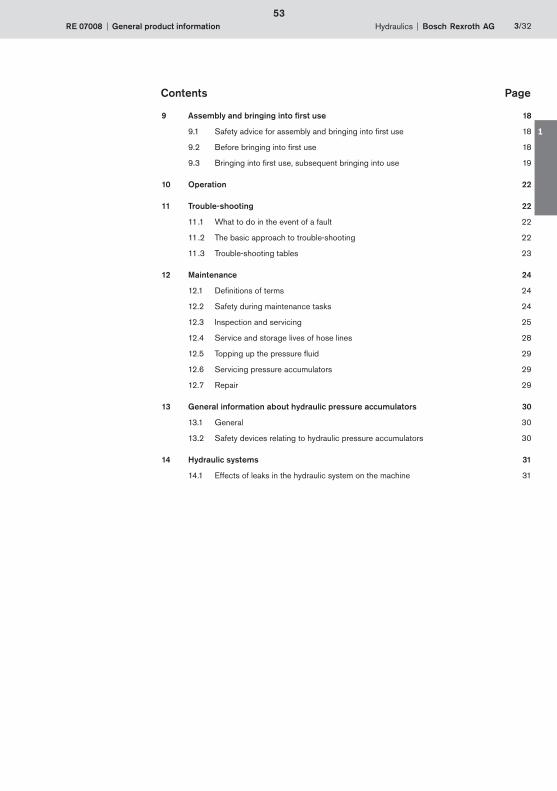
9 Assembly and bringing into fi rst use 18
9.1 Safety advice for assembly and bringing into fi rst use 18
9.2 Before bringing into fi rst use 18
9.3 Bringing into fi rst use, subsequent bringing into use 19
10 Operation 22
11 Trouble-shooting 22
11.1 What to do in the event of a fault 22
11.2 The basic approach to trouble-shooting 22
11.3 Trouble-shooting tables 23
12 Maintenance 24
12.1 Defi nitions of terms 24
12.2 Safety during maintenance tasks 24
12.3 Inspection and servicing 25
12.4 Service and storage lives of hose lines 28
12.5 Topping up the pressure fl uid 29
12.6 Servicing pressure accumulators 29
12.7 Repair 29
13 General information about hydraulic pressure accumulators 30
13.1 General 30
13.2 Safety devices relating to hydraulic pressure accumulators 30
14 Hydraulic systems 31
14.1 Effects of leaks in the hydraulic system on the machine 31
53
1
4/32 Bosch Rexroth AG Hydraulics General product information RE 07008
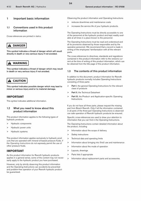
1 Important basic information
1.1 Conventions used in this product information
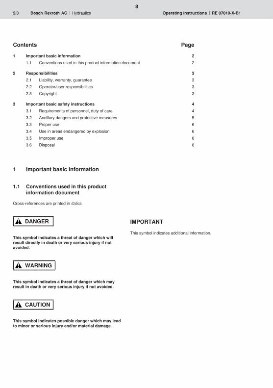
Cross-references are printed in italics.
DANGER
This symbol indicates a threat of danger which will result directly in death or very serious injury if not avoided.
WARNING
This symbol indicates a threat of danger which may result in death or very serious injury if not avoided.
CAUTION
This symbol indicates possible danger which may lead to minor or serious injury and/or to material damage.
IMPORTANTThis symbol indicates additional information.
1.2 What you need to know about this product information
This product information applies to the following types of hydraulic products:
Hydraulic components
Hydraulic power units
Hydraulic systems.
This product information applies exclusively to hydraulic prod-ucts that are operated with mineral-oil-based pressure fl uids, if the Operating Instructions do not expressly permit the use of other pressure fl uids.
IMPORTANTAs this product information for Rexroth hydraulic products applies in a general sense, some of the content may not neces-sarily apply to the hydraulic product you have purchased.
However, only by strictly observing this product information and the Operating Instructions can accidents be prevented and problem-free operation of your Rexroth hydraulic product be guaranteed.
Observing the product information and Operating Instructions
reduces downtimes and maintenance costs
increases the service life of your hydraulic products.
The Operating Instructions must be directly accessible to one of the personnel at the hydraulic product and kept readily avail-able at all times in a place known to the personnel.
The Operating Instructions must be read and understood and all its provisions observed by those responsible and by the operative personnel. We recommend that a record is made in writing of the employees’ familiarisation with all the relevant parts.
The cross-references to directives, standards and regulations contained in this product information refer to the versions cur-rent at the time of writing of this product information, which can be obtained from the title page of this product information.
1.3 The contents of this product information
In addition to this document, product information for Rexroth hydraulic products normally includes Operating Instructions consisting of three parts:
Part I, the general Operating Instructions for the relevant class of products
Part II, the Technical Datasheet
Part III, the Product- and Application-specifi c Operating Instructions.
If you do not have all three parts, please request the missing part from Bosch Rexroth. Only if all the information contained in all parts of the three-part Operating Instructions is observed can safe operation of Rexroth hydraulic products be ensured.
Specifi c cross-references are used to draw your attention to information that you can fi nd in the Operating Instructions.
The Operating Instructions contain detailed information about the product, including
Information about the scope of delivery
Safety instructions
Technical data and operating limits
Information about bringing into (fi rst) use and maintenance
Information about the mode of operation
Layouts, drawings
Parts lists if appropriate
Information about replacement parts and accessories.
54
Hydraulics Bosch Rexroth AGRE 07008 General product information 5/32
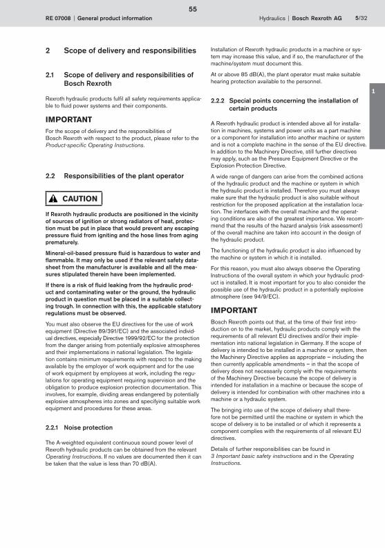
2 Scope of delivery and responsibilities
2.1 Scope of delivery and responsibilities of Bosch Rexroth
Rexroth hydraulic products fulfi l all safety requirements applica-ble to fl uid power systems and their components.
IMPORTANTFor the scope of delivery and the responsibilities of Bosch Rexroth with respect to the product, please refer to the Product-specifi c Operating Instructions.
2.2 Responsibilities of the plant operator
CAUTION
If Rexroth hydraulic products are positioned in the vicinity of sources of ignition or strong radiators of heat, protec-tion must be put in place that would prevent any escaping pressure fl uid from igniting and the hose lines from aging prematurely.
Mineral-oil-based pressure fl uid is hazardous to water and fl ammable. It may only be used if the relevant safety data-sheet from the manufacturer is available and all the mea-sures stipulated therein have been implemented.
If there is a risk of fl uid leaking from the hydraulic prod-uct and contaminating water or the ground, the hydraulic product in question must be placed in a suitable collect-ing trough. In connection with this, the applicable statutory regulations must be observed.
You must also observe the EU directives for the use of work equipment (Directive 89/391/EC) and the associated individ-ual directives, especially Directive 1999/92/EC for the protection from the danger arising from potentially explosive atmospheres and their implementations in national legislation. The legisla-tion contains minimum requirements with respect to the making available by the employer of work equipment and for the use of work equipment by employees at work, including the regu-lations for operating equipment requiring supervision and the obligation to produce explosion protection documentation. This involves, for example, dividing areas endangered by potentially explosive atmospheres into zones and specifying suitable work equipment and procedures for these areas.
2.2.1 Noise protection
The A-weighted equivalent continuous sound power level of Rexroth hydraulic products can be obtained from the relevant Operating Instructions. If no values are documented then it can be taken that the value is less than 70 dB(A).
Installation of Rexroth hydraulic products in a machine or sys-tem may increase this value, and if so, the manufacturer of the machine/system must document this.
At or above 85 dB(A), the plant operator must make suitable hearing protection available to the personnel.
2.2.2 Special points concerning the installation of certain products
A Rexroth hydraulic product is intended above all for installa-tion in machines, systems and power units as a part machine or a component for installation into another machine or system and is not a complete machine in the sense of the EU directive. In addition to the Machinery Directive, still further directives may apply, such as the Pressure Equipment Directive or the Explosion Protection Directive.
A wide range of dangers can arise from the combined actions of the hydraulic product and the machine or system in which the hydraulic product is installed. Therefore you must always make sure that the hydraulic product is also suitable without restriction for the proposed application at the installation loca-tion. The interfaces with the overall machine and the operat-ing conditions are also of the greatest importance. We recom-mend that the results of the hazard analysis (risk assessment) of the overall machine are taken into account in the design of the hydraulic product.
The functioning of the hydraulic product is also infl uenced by the machine or system in which it is installed.
For this reason, you must also always observe the Operating Instructions of the overall system in which your hydraulic prod-uct is installed. It is most important for you to also consider the possible use of the hydraulic product in a potentially explosive atmosphere (see 94/9/EC).
IMPORTANTBosch Rexroth points out that, at the time of their fi rst intro-duction on to the market, hydraulic products comply with the requirements of all relevant EU directives and/or their imple-mentation into national legislation in Germany. If the scope of delivery is intended to be installed in a machine or system, then the Machinery Directive applies as appropriate – including the then currently applicable amendments – in that the scope of delivery does not necessarily comply with the requirements of the Machinery Directive because the scope of delivery is intended for installation in a machine or because the scope of delivery is intended for combination with other machines into a machine or a hydraulic system.
The bringing into use of the scope of delivery shall there-fore not be permitted until the machine or system in which the scope of delivery is to be installed or of which it represents a component complies with the requirements of all relevant EU directives.
Details of further responsibilities can be found in 3 Important basic safety instructions and in the Operating Instructions.
55
1
6/32 Bosch Rexroth AG Hydraulics General product information RE 07008
2.3 Liability, guarantee, warranty
Bosch Rexroth shall not be liable for damages that result from non-compliance with or disregard of these and other parts of the Operating Instructions.
Unauthorised tampering shall render the warranty null and void.
Bosch Rexroth shall only be liable if the scope of delivery was shown to be defective. Bosch Rexroth shall not be liable if a defi ciency occurs that involves parts having been replaced by the customer with equivalent but not identical parts as speci-fi ed by the manufacturer.
Please refer to our general terms of supply or your contract for details of the guarantee and manufacturer’s warranty.
2.4 Copyright
This product information may only be reproduced – electroni-cally or mechanically, in whole or in part – with the express writ-ten permission of Bosch Rexroth. It may likewise not be distrib-uted, amended, transmitted, translated into another language or employed or copied for other purposes or by other parties without such consent.
56
Hydraulics Bosch Rexroth AGRE 07008 General product information 7/32
3 Important basic safety instructions
3.1 What to do in an emergency
In the event of an emergency, fault or other abnormal occur-rences:
1. Switch off the hydraulic system.
2. Secure the main switch against being unintentionally switched on again.
3. Secure the danger area so that no one can enter the dan-ger area unknowingly or uncontrolled.
4. Notify the relevant specialist personnel immediately.
5. In the event of fi re, observe the provisions of the safety datasheets issued by the manufacturer of the pressure fl uid and the fi re precautions specifi cally applicable to your place of work, which must be documented in the plant operator’s operating manual.
WARNING
Fighting fi res with materials other than those permitted can lead to explosions and/or more rapid spread of the fi re! Danger to life from smoke inhalation!
3.2 Safety labelling on the hydraulic product
IMPORTANTThe meanings of the safety labelling on the Rexroth prod-uct are explained in the Operating Instructions.
For a diagram of the nameplate and an explanation of the information on it please refer to the Operating Instructions.
3.3 Proper use
Rexroth hydraulic products are designed and constructed for the provision, transmission, control or regulation of energy and signals using the fl ow of oil.
Unless otherwise agreed, the Rexroth hydraulic product satis-fi es at least safety category B in accordance with EN 954-1.
If the hazard analysis/risk assessment of the overall machine in which the Rexroth hydraulic product is to be installed indi-cates that a safety category higher than category B in accor-dance with EN 954-1 is required for the Rexroth hydraulic product, then a correspondingly higher rated hydraulic product can be supplied and installed only after special agreement with Bosch Rexroth.
IMPORTANTThe hydraulic product shall be operated exclusively with pres-sure fl uids complying with DIN 51524. Where other pressure fl uids are permitted, for example brake fl uids for brake valves, this is specially mentioned in the Operating Instructions.
For details on proper use see 4 Technical data and ambient conditions.
The following information can be found in the Operating Instructions:
the proper use, specifi c to the hydraulic product
where applicable, the safety category in accordance with EN 954-1
non-permitted and improper use.
3.3.1 Proper use, requirements before operation
Rexroth hydraulic products may only be operated if they are in perfect technical condition.
• In the event of disturbances in the power supply and/or damage to the electrical equipment, switch off immediately and secure the main switch against being switched on again without authorisation.
• Report and rectify all faults and damage indicated by the system or discovered by other means.
The connections, operating conditions and performance data specifi ed in the Operating Instructions must be observed and never changed.
Rexroth hydraulic products shall not be converted or otherwise modifi ed without prior consultation with Bosch Rexroth.
The plant operator shall not modify the program code of programmable control systems.
Dependencies and time factors shall not be modifi ed with-out prior consultation.
The safety devices fi tted by Rexroth must be present, properly installed and in full working order – except when this is impractical during setting up or maintenance work. They shall not be relocated, bypassed or rendered ineffec-tive.
Safety components such as limit switches, valves and other control components shall not be rendered inopera-tive.
Tamperproof lead seals installed by the manufacturer shall not be removed or damaged except when this is neces-sary in the course of maintenance tasks defi ned in the Operating Instructions.
The specifi ed maintenance tasks in the Operating Instruc-tions shall be carried out at the intervals stated in the Operating Instructions.
57
1
8/32 Bosch Rexroth AG Hydraulics General product information RE 07008
Uncontrolled access by persons unfamiliar with the sys-tem to the immediate operating zone of Rexroth hydraulic products is prohibited (even if the product in question has been shut down).
Rexroth hydraulic products must never be assembled, operated or maintained by persons under the infl uence of alcohol, drugs or other medication which affect one’s abil-ity to react.
3.4 Requirements for personnel, duty of care
3.4.1 Qualifi cations of specialist personnel
A specialist person is someone who, using his specialist train-ing, knowledge and experience as well as familiarity with the relevant conditions, can
safely carry out the tasks allocated to him and correctly assess the scope and implications of his work
recognise possible dangers
undertake the necessary measures to eliminate possible accidents.
3.4.2 Requirements for hydraulics maintenance personnel
In accordance with DIN 31051, maintenance comprises the individual activities of inspection, servicing and repair. All personnel involved in maintenance shall be familiar with and observe all parts of the Operating Instructions and this product information.
Inspection personnel shall fulfi l the following requirements:
They have been instructed in the relevant activity.
Specialist knowledge of hydraulics is not required for purely inspection activities but the personnel must be aware of the particular dangers associated with hydraulic products.
Servicing personnel (who carry out fi lter and oil changes, for example) shall fulfi l the following requirements:
They have been instructed in the relevant activity.
Specialist knowledge of hydraulics is not required to carry out servicing work.
Repair personnel shall fulfi l the following requirements:
The personnel must be hydraulics experts, who have been instructed and meet the defi nition given above,
Repair personnel must be familiar with the function of the hydraulic system as a whole, from subsystems to their interaction with the function of the entire machine.
Repair personnel must be able to read hydraulic circuit diagrams, interpret individual functions from their symbols and understand function diagrams.
Repair personnel must possess knowledge of the function and construction of hydraulic elements.
3.4.3 Requirements for electrical maintenance personnel
All work on electrical equipment shall only be carried out by an authorised, qualifi ed electrician, or by instructed persons under the guidance and supervision of a qualifi ed electrician, in accordance with the rules applicable to electrotechnical prod-ucts.
3.4.4 Minimum age
Persons under the age of 18 who are currently receiving instruction or training or are working under supervision may not work on Rexroth hydraulic products.
This does not apply to young persons of 16 or over if
working on Rexroth hydraulic products is necessary in order for them to accomplish a training objective
their protection is guaranteed by the supervision of an experienced, competent person
they are allowed to use only tools, work implements and protective gear that preclude the risk of injury.
58
Hydraulics Bosch Rexroth AGRE 07008 General product information 9/32
3.4.5 Training
The plant operator using Bosch Rexroth hydraulic products shall train his personnel regularly in the following subjects:
Observation and use of the Operating Instructions and legal requirements
Proper operation of the Rexroth hydraulic product
Observation of the instructions of safety offi cers and the plant operator’s operating manual
What to do in an emergency.
IMPORTANTBosch Rexroth can provide you with training support in special-ist areas.
An overview of the training can be found on the Internet at http://www.boschrexroth.de/didactic.
3.5 General ancillary dangers and protective measures when operating hydraulic products
DANGER
In the interests of your safety, all safety instructions shall be carefully observed, especially those in the Operating Instruc-tions.
In spite of the high intrinsic safety of Rexroth hydraulic prod-ucts, the risk of personal injury or damage to the environment cannot be excluded, even when the equipment is properly used.
New, additional dangers may arise if the hydraulic product is installed in another machine or installed with other machines in a system. This shall apply in particular to mechanical move-ments generated by the hydraulic product.
Information on these additional dangers can be found in the overall operating manual of the supplier of the overall system in which the hydraulic product is installed.
3.5.1 Dangers from pressure fl uid
CAUTION
Handling pressure fl uid without protection is hazardous to health.
Please observe the manufacturer’s safety instructions and the safety datasheets for the pressure fl uid that you are using.
DANGER
Serious damage to health or death may result if pressure fl uid enters the blood stream or is swallowed. If this occurs, contact a doctor immediately!
3.5.2 Malfunctions due to contamination of pressure fl uid
Contamination of the pressure fl uid can be caused by:
Wear during operation of the machine/system (metallic and non-metallic abrasion)
Leaks of the hydraulic product
Contaminants introduced during servicing/repair
The use of dirty (unfi ltered) pressure fl uid when the pres-sure fl uid is changed.
Contaminants lead to malfunctions, increased wear and shorter service life of the hydraulic product. This can have negative effects on the safety and reliability of the hydraulic product.
Therefore the maintenance tasks specifi ed in the Operating Instructions shall be carried out at regular intervals and the utmost cleanliness is required during work on the hydraulic product.
CAUTION
When changing the pressure fl uid, always use factory-fresh pressure fl uid and fi lter it before fi lling to remove any contami-nants in the pressure fl uid that it often contains from the pack-aging container (drum). Flush out lines and hoses before instal-lation.
The cleanliness class of a pressure fl uid is specifi ed in accor-dance with ISO 4406. Detailed information can be obtained from the relevant datasheet or the Operating Instructions.
59
1
10/32 Bosch Rexroth AG Hydraulics General product information RE 07008
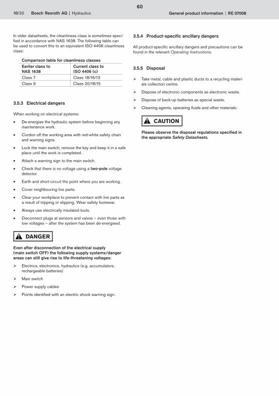
In older datasheets, the cleanliness class is sometimes speci-fi ed in accordance with NAS 1638. The following table can be used to convert this to an equivalent ISO 4406 cleanliness class:
Comparison table for cleanliness classesEarlier class to NAS 1638
Current class to ISO 4406 (c)
Class 7 Class 18/16/13Class 9 Class 20/18/15
3.5.3 Electrical dangers
When working on electrical systems:
• De-energise the hydraulic system before beginning any maintenance work.
• Cordon off the working area with red-white safety chain and warning signs.
• Lock the main switch, remove the key and keep it in a safe place until the work is completed.
• Attach a warning sign to the main switch.
• Check that there is no voltage using a two-pole voltage detector.
• Earth and short-circuit the point where you are working.
• Cover neighbouring live parts.
• Clear your workplace to prevent contact with live parts as a result of tripping or slipping. Wear safety footwear.
• Always use electrically insulated tools.
• Disconnect plugs at sensors and valves – even those with low voltages – after the system has been de-energised.
DANGER
Even after disconnection of the electrical supply (main switch OFF) the following supply systems/danger areas can still give rise to life-threatening voltages:
Electrics, electronics, hydraulics (e.g. accumulators, rechargeable batteries)
Main switch
Power supply cables
Points identifi ed with an electric shock warning sign.
3.5.4 Product-specifi c ancillary dangers
All product-specifi c ancillary dangers and precautions can be found in the relevant Operating Instructions.
3.5.5 Disposal
Take metal, cable and plastic ducts to a recycling materi-als collection centre.
Dispose of electronic components as electronic waste.
Dispose of back-up batteries as special waste.
Cleaning agents, operating fl uids and other materials:
CAUTION
Please observe the disposal regulations specifi ed in the appropriate Safety Datasheets.
60
Hydraulics Bosch Rexroth AGRE 07008 General product information 11/32
4 Technical data and ambient conditions
IMPORTANTThe product-specifi c technical data, operating limits and ambi-ent conditions for the operation of your Rexroth hydraulic prod-uct can be found in the Operating Instructions.
This includes the following information:
Minimum fl ow rate for adequate cooling
Permissible maximum temperature of the coolant
Performance data
Type of control and regulation functions
Permissible pressures, fl ow rates
Connections.
4.1 Information about pressure fl uids
Unless otherwise indicated in the Operating Instructions, the following specifi cation applies to the pressure fl uid to be used:
Mineral-oil-based pressure fl uid complying with the requirements of DIN 51524.
Operating temperature range 0 °C…+80 °C (in tank < 72 °C).
Any deviations from this can be found in the Operating Instruc-tions.
IMPORTANTBosch Rexroth recommends a maximum operating tempera-ture of 55 °C, because the rate of ageing of the pressure fl uid increases and the service life of the seals and hoses is reduced at higher temperatures.
Viscosity ranges: see RE 07075 and RE 90220
Max. permissible contamination class of the pressure fl uid in accordance with ISO 4406: see 3.5.2 Malfunctions due to contamination of pressure fl uid.
The maximum permissible cleanliness class can be found in the Operating Instructions. The following types of pressure fl uids shall be used.
IMPORTANTRexroth hydraulic components are tested with test oil MZ45 manufactured by ESSO (class ISO VG 46 at 40 °C), (Viscosity η = approx. 46 mm2/s).
4.2 Ambient conditions
4.2.1 Use in potentially explosive atmospheres
DANGER
Rexroth hydraulic products shall be used in potentially explosive atmospheres only if they are designed for this purpose and this is expressly stated in the Operating Instructions.
IMPORTANTDirective 1999/92/EC of the European Parliament and Coun-cil dated 16 December 1999 concerning the minimum require-ments for improving the safety and health protection of work-ers potentially at risk from explosive atmospheres governs protection from danger from potentially explosive atmospheres. Observe the requirements contained in the regulations for operating equipment requiring supervision and the obligation to produce explosion protection documentation. This involves, for example, dividing areas endangered by poten-tially explosive atmospheres into zones and specifying suitable work equipment and procedures for these areas.
Observe the requirements of Directive 94/9/EC of the Euro-pean Parliament and Council dated 23 March 1994 on the approximation of laws of the member states concerning equip-ment and protective systems intended for use in potentially explosive atmospheres (ATEX Product Directive) and/or the corresponding national legislation by means of which the Direc-tive was implemented in law in the EU member states. The directive contains requirements for the use of equipment and protective systems in potentially explosive atmospheres.
61
1
12/32 Bosch Rexroth AG Hydraulics General product information RE 07008
4.2.2 Climatic operating conditions
Unless otherwise indicated in the Operating Instructions, the permissible ambient temperature
for control units: 0 °C…+50 °C
for drive units with electric motors without heat exchang-ers, surface-cooled by free air circulation: 0 °C…+30 °C
for drive units with heat exchangers: < +40 °C.
Unless otherwise specifi ed, Rexroth hydraulic products are designed for use in temperate climate zones and in covered areas (not in the open air) at relative air humidities of < 70 % and at room temperatures of 22 °C.
IMPORTANTFor systems with oil-air heat exchangers:Observe the information given in the circuit diagram in the Operating Instructions.
In relation to the electronic equipment, the permissible ambient conditions apply to installed and protected electrical connec-tions of class IP 55.
Ambient temperature +5 °C…+40 °Cassuming that the average air temperature over a 24 hour period does not exceed +35 °C.
Relative air humidity: 23…95 %, non-condensing.
Altitude: up to 1000 m above national datum.
DANGER
Rexroth hydraulic products shall not be used in aeronau-tical equipment, except where they have been specially approved and appropriately labelled to this effect.
62

Hydraulics Bosch Rexroth AGRE 07008 General product information 13/32
5 What you need to know about pressure fl uids
5.1 How to handle pressure fl uids safely
DANGER
Mineral-oil-based pressure fl uid is hazardous to water and fl ammable. It may only be used if the relevant safety datasheet from the manufacturer is present and all the measures stipu-lated therein have been implemented.
5.2 Functions and effectiveness
Due to the many tasks of pressure fl uid, its selection, inspec-tion and maintenance are of vital importance for:
proper functioning
operating safety
service life
and the cost effectiveness of the hydraulic product.
The tasks of pressure fl uid:
to transmit hydraulic energy from the pump to the hydrau-lic cylinder/motor
to lubricate parts moving against one another
corrosion protection
to remove contaminants
to remove locally accumulated heat.
5.2.1 Reduced function due to ageing
The effectiveness of pressure fl uid diminishes as it ages (undergoes chemical changes). Acids and resinous residues form, which may cause valve spools to stick.
The following factors accelerate the ageing process:
high temperatures
oxygen in the pressure fl uid
air humidity
water
metallic catalysers
operating pressure
contaminants.
IMPORTANTObserve the following rules of thumb: At pressure fl uid temperatures >70 °C, the rate of ageing doubles for each 10 °C.
5.3 Viscosity
5.3.1 Viscosity grades
The most important characteristic of a pressure fl uid is its vis-cosity, i.e. stickiness. Viscosity range always plays a priority role in the selection of a pressure fl uid.
Viscosity is measured in the SI unit [mm2/s]. Many manufactur-ers still provide their information in centiStoke [cSt], the equiv-alent of [mm2/s].
The viscosity grades (VG = viscosity grade) in accordance with ISO 3448 relate to the viscosity at 40 °C. The viscosity grade is appended to the type designation or the commercial name of the pressure fl uid. Example: A pressure fl uid with a viscosity grade of ISO VG 46 has a viscosity of 46 mm2/s at 40 °C.
The relationship between medium temperature and viscosity for hydraulic oil (example)
Medium temperature Viscosity
3 °C 800 mm2/s8 °C 500 mm2/s
25 °C 100 mm2/s60 °C 20 mm2/s77 °C 12 mm2/s
Too high a viscosity leads to the formation of air and vapour bubbles as a result of low pressure (cavitation). Too low a vis-cosity leads to increased leakage losses. Increased leakage losses cause the pressure fl uid to heat up more, leading in turn to a further reduction in viscosity. The pressure fl uid then loses its ability to lubricate.
Valves, pumps and hydraulic motors, in particular, require exact compliance with the defi ned viscosity ranges.
For certain ambient and operating temperatures, not all the requirements can always be covered with the available ranges of the viscosity grades.
In order to comply with all the requirements, high viscosity pressure fl uids with viscosity index improvers or a pressure fl uid cooler/heater may be used.
63
1
14/32 Bosch Rexroth AG Hydraulics General product information RE 07008
5.4 Leakage fl uid
Clearances and play mean that some leakage fl uid escapes from all hydraulic products. Leakage fl uid can be lead away internally or externally, depending on the component. It can be fed back into the tank or must be disposed of.
CAUTION
Make sure that the leakage fl uid is fed back into the tank in a proper manner.Dispose of leakage fl uid that is not fed back into the tank properly, in compliance with the applicable environmental protection regulations.
5.5 Topping up/refi lling
CAUTION
When topping up/refi lling your hydraulic system, make sure that you use pressure fl uid of the same sort and type and from the same manufacturer.
If the fl uid is heavily contaminated or prematurely aged, then the system, including the tank must be cleaned and fl ushed before refi lling. New pressure fl uid must always be fi ltered in accordance with the required cleanliness class, as it does not normally meet the required cleanliness class in the as-supplied state.
64

Hydraulics Bosch Rexroth AGRE 07008 General product information 15/32
6 Construction and mode of operation of a hydraulic system
6.1 Defi nitions of terms
Hydraulics (fl uid technology)
Transmission, control and distribution of energy and signals using a pressurised fl uid medium.
Hydraulic system
Arrangement of interconnected components for transferring and controlling hydraulic energy.
Component
A single unit (e.g. a valve, fi lter, cylinder, motor) that consists of one or more parts and which is a functional constituent of a hydraulic system.
Drive
A component that converts the energy of the hydraulic fl uid into mechanical energy (e.g. motor, cylinder).
6.2 Schematic
In a system operated with hydraulic oil, fi rst of all mechani-cal energy is converted into hydraulic energy, transported and controlled in this form, to fi nally be converted once more into mechanical work.
The hydraulic elements are arranged in accordance with these functions. The following diagram shows a schematic represen-tation of the elements of a complete hydraulic system.
To demonstrate their operating principle, standardised symbols (ISO 1219) are used instead of sectional diagrams of the vari-ous devices. Line connections are represented by simple lines, as can be seen in the example.
1
23
4
5
6
7
8
9
1 TankOil preparation
2 Filter
3 Pump Energy conversion
4 Pressure limiting valve
Energy control5 Directional valve
6 Check valve
7 Throttle valve
8 Hydraulic cylinderEnergy conversion
9 Hydraulic motor
6.3 Safety concept
Hydraulic products contain sensors and actuators, the interac-tion of which is particularly important with regard to the fulfi l-ment of technical safety functions.
Individual hydraulic products form part of an overall safety con-cept.
Applications required to perform safety functions are designed using special hydraulic components that satisfy the require-ments of the relevant directives, such as the Pressure Equip-ment Directive and other standards.
The manufacturer of the overall machine or system defi nes and bears responsibility for the safety category to EN 954-1 to be fulfi lled.
IMPORTANTA more detailed description of the safety concept and the spe-cifi c safety components installed can be found in the Operating Instructions and the Operating Instructions of the supplier of the overall system in which the hydraulic product is installed.
65
1

16/32 Bosch Rexroth AG Hydraulics General product information RE 07008
7 Moving hydraulic units/components
Hydraulic units or components may be moved by a fork-lift truck or a hoist, depending on their size and the local condi-tions.
IMPORTANTFor details see the Operating Instructions.
CAUTION
Always ensure hydraulic products are empty of pressure fl uid for transportation.
Rexroth hydraulic products are delivered empty of pressure fl uid. However, products may contain oil residues left over from the fi nal inspection at our factory.
8 Storage and longer standstills
8.1 Hydraulic systems - subsequent bringing into use after storage
Corrosion, especially oxidation, can cause metal surfaces to lose the standard of surface fi nish required for the hydraulic system to function properly.
Rust and other metallic and non-metallic particles lead to abra-sive wear (erosion), which detrimentally affects the functioning of the hydraulic system.
CAUTION
If a hydraulic system is to be brought into use again fol-lowing a long standstill, it must fi rst be fl ushed clean.
8.1.1 Factory-applied corrosion protection
Rexroth hydraulic products are tested in accordance with Class III using a hydraulic oil that has additional anti-corrosive properties. The fi lm of oil that remains in the product after the test provides suffi cient internal corrosion protection.
This factory lubrication ensures that valves do not stick during subsequent use of the hydraulic product, and guarantees com-patibility with seals and the pressure fl uid to be used.
IMPORTANTThe factory-applied corrosion protection is adequate provided that
no condensation or leakage water can enter the system
long standstills are avoided.
Contact Bosch Rexroth if you are not clear about the conse-quences of long standstills on the state of the hydraulic prod-uct.
8.1.2 Storage times in relation to the ambient conditions
Delays in bringing into use, long shipping and storage times or long periods of non-use can lead to rust formation in Rexroth hydraulic products. Additional corrosion protection measures must be implemented to prevent this.
IMPORTANTIf all the openings on the hydraulic products are not sealed so as to be air-tight, this will reduce the storage life of the hydrau-lic product by nine months.After the specifi ed storage time has expired, in any event not longer than 24 months, the corrosion protection must be checked and further conservation measures applied if neces-sary.
66

Hydraulics Bosch Rexroth AGRE 07008 General product information 17/32
8.2 Seals, hoses and hose lines
CAUTION
Seals:Observe the requirements of ISO 2230 and/or DIN 7716 and the specifi c manufacturer’s data on seals.
Hoses and hose lines:In the Federal Republic of Germany, please observe the requirements of DIN 20066, ZH 1/74 Safety rules for hydraulic hose lines and the specifi c manufacturer’s data on hoses and hose lines.
In addition, the following conditions shall be observed:
Seals, hoses and hose lines are stored in cool, dry and dust-free conditions.
The hoses and hose lines can be enclosed in plastic foil to ensure low-dust storage conditions. Ideal storage conditions for hoses and hose lines are temperatures from +15 °C to +25 °C and a relative humidity of below 65 %.
Do not store elastomers below –10 °C. The ideal stor-age conditions for seals are temperatures from +10 °C to +20 °C and a relative humidity of between 65 % and 75 %.
Store hoses and hose lines in the original packaging if possible. Prevent the entry of air.
Avoid direct sunlight and UV radiation and shield from nearby sources of heat.
Darkened storage locations are preferred.
Do not use ozone-forming light sources or equipment (e.g. fl uorescent lamps, mercury-vapour lamps, copiers, laser printers) or electrical spark-forming devices in the vicinity of hoses and hose lines.
Seals, hoses and hose lines must not come into contact in particular with materials or vapours that could damage them (e.g. acids, alkalis, solvents).
Store seals, hoses and hose lines lying down and free from tension. If the hoses and hose lines are coiled, take care not to bend them to less than the smallest bending radius specifi ed by the manufacturer.
Maximum storage times
NBR seals: 4 years
FKM seals: 10 years
Hoses: 4 years
Hose lines: 2 years
For reasons of safety, seals, hoses/hose lines shall not be used once these permissible storage times are reached or exceeded. Permissible storage times could be considerably reduced if the permissible storage conditions are not main-tained. If you are not clear about the storage times and/or stor-age conditions then you should not use the product.
67
1
18/32 Bosch Rexroth AG Hydraulics General product information RE 07008
9 Assembly and bringing into fi rst use
IMPORTANTOnly the permissible pressure fl uids given in the Operating Instructions are to be used. Information on other pressure fl u-ids can be found in the Operating Instructions or are available on request.
Filling the pressure fl uid tank must always take place through a suitable fi lter unit. Experience has shown that even new pres-sure fl uid can often have more than the maximum permissible level of contamination.
All information specifi c to assembly and bringing into fi rst use can be found in the Operating Instructions.
Pay attention to cleanliness:
Do not use cleaning wool or cloths containing fi bres for cleaning.
Depending on the condition of the system or machine, cleaning with fi bre-free cloths may be suffi cient. Use suit-able liquid cleaning agents to remove lubricants and other stronger contaminants. Make sure that cleaning agent does not get into the hydraulic system.
Never use hemp and putty as sealants.
The functional or failure behaviour of identical hydraulic prod-ucts may vary due to conditions specifi c to the machine or sys-tem in which the hydraulic product is installed (mass, speed, electrical triggering at setpoint values, etc.), see also Section 11 Trouble-shooting.
9.1 Safety advice for assembly and bringing into fi rst use
DANGER
Hydraulic products are generally intended for installation in machines/systems or devices.
The function of the hydraulic product must therefore always be seen in relation to the function of this machine – i.e. seemingly identical hydraulic products may demon-strate different functional behaviours as a result of the function of the machine in which they are installed.
For this reason, a hydraulic drive must not be brought into use until it has been determined that the machine in which it is installed conforms to EU standards.
Do not bring hydraulic drives into use until you have famil-iarised yourself completely, fi rstly with the function of the hydraulic product and hydraulic equipment and secondly with the hydraulically powered machine functions, and have clarifi ed and dealt with any possible dangers.
Bringing into (fi rst) use shall only be done by an instructed, authorised hydraulics expert who has the required special-ist knowledge.
Specialist hydraulics knowledge means, among other things, that the person can read and fully understand hydraulics draw-ings. In particular, he must fully comprehend the range of func-tions of the integrated safety components as part of the overall safety concept.
9.2 Before bringing into fi rst use
1. Check the scope of delivery for transport damage.
2. Check that the Operating Instructions for the Rexroth hydraulic product are present and complete.Contact us if the Operating Instructions are not there or are incomplete.
3. Assemble the hydraulic product.
• Observe the Operating Instructions and this product information.
• Assemble the hydraulic components, so that they are mounted strain-free on even surfaces.
• Tighten the fastening bolts evenly using the specifi ed tightening torque.
4. Ensure that the interfaces of the system/machine and the installation conditions provide for safe operation of the hydraulic product. If in doubt, consult the people responsi-ble for the overall system/functional machine.
5. Check the construction of the hydraulic product against the circuit diagrams, lists of equipment and assem-bly drawings. If there are any differences, draw this to the attention of the people responsible. If important documents are missing, they can be requested from Bosch Rexroth. Only documents issued by the bodies authorised to do so shall be used.
6. Based on the Operating Instructions for the system or machine in which the hydraulic product is installed, check whether bringing the hydraulic system into use could lead to uncontrolled, dangerous movements. Where appropri-ate, take into account the hazard analysis/risk assessment for the system or machine.
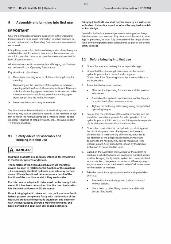
7. Take the precautions appropriate to the anticipated dan-gers, e.g.
• Ensure that the cylinder piston rod can move out without danger.
• Use a hoist or other lifting device to additionally secure lifted loads.
68
Hydraulics Bosch Rexroth AGRE 07008 General product information 19/32
8. As part of bringing into (fi rst) use, check whether the elec-tric motors and valve solenoids can be switched manually using the electrical controls of the system/machine. If they cannot be switched manually – or can but with diffi culty – you must provide a remote control (e.g. test boxes for Rexroth proportional valves) for the internal function test of the hydraulic system.
IMPORTANTStarting up the hydraulics solely by means of emergency man-ual operation is not recommended, as several valves at once cannot be switched as required in the correct sequence.
9. Draw up a sequential program for bringing into (fi rst) use and store it with the technical documentation as an appen-dix to the Operating Instructions.For this you should consider the following: Hydraulic drives basically consist of the following func-tional groups
Pump circuit (generation of pressurised oil fl ow); pump, electric motor, oil tank, fi lters, monitoring devices, etc.
Control system for at least one hydraulic consumer (cylinder, motor); directional control valves, pressure and fl ow control valves, check valves
Hydraulic consumers (cylinders, motors) with spe-cially assigned valves, e.g. braking valve.
10. Divide the functional circuit diagram into separate mini-cir-cuits that can each be started up in succession.
11. Read the functional circuit diagram and seek clarifi cation of any unclear text or diagrams. More information about the functioning of components, e.g. a pump regulator, is available in the Technical Datasheet.
12. Establish into which position valves are to be switched, or how valves are to be set.
13. Put up any necessary directional, prohibitive or informative signs and check whether the meaning of these signs are explained in the Operating Instructions.
14. Follow this sequence for bringing into (fi rst) use
Pump circuit
Parts of control system:e.g. pressure cut-off and switchover, open centre, pressure reduction etc.
Cylinder and motor circuits:First move, fi ll and bleed, then fi nally optimise all settings.
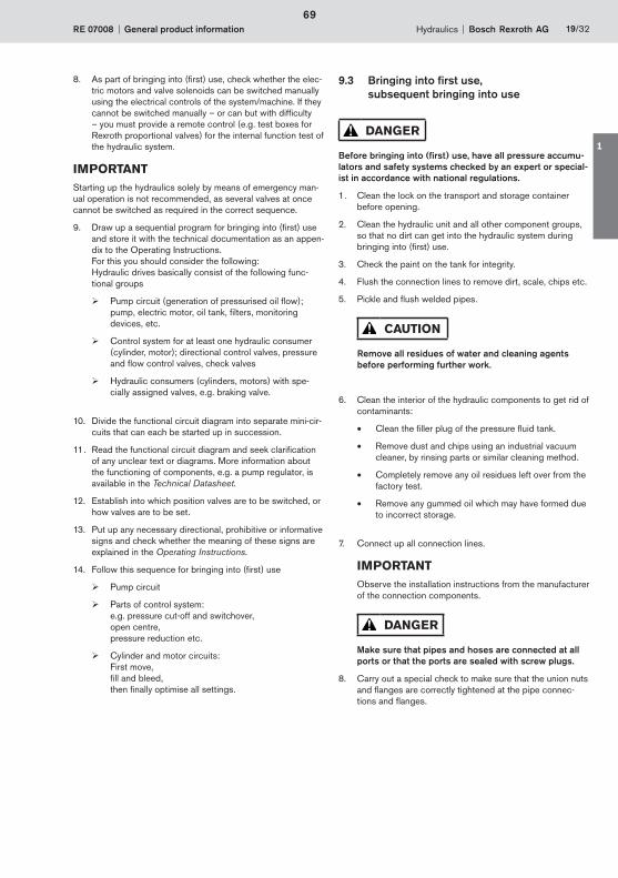
9.3 Bringing into fi rst use, subsequent bringing into use
DANGER
Before bringing into (fi rst) use, have all pressure accumu-lators and safety systems checked by an expert or special-ist in accordance with national regulations.
1. Clean the lock on the transport and storage container before opening.
2. Clean the hydraulic unit and all other component groups, so that no dirt can get into the hydraulic system during bringing into (fi rst) use.
3. Check the paint on the tank for integrity.
4. Flush the connection lines to remove dirt, scale, chips etc.
5. Pickle and fl ush welded pipes.
CAUTION
Remove all residues of water and cleaning agents before performing further work.
6. Clean the interior of the hydraulic components to get rid of contaminants:
• Clean the fi ller plug of the pressure fl uid tank.
• Remove dust and chips using an industrial vacuum cleaner, by rinsing parts or similar cleaning method.
• Completely remove any oil residues left over from the factory test.
• Remove any gummed oil which may have formed due to incorrect storage.
7. Connect up all connection lines.
IMPORTANTObserve the installation instructions from the manufacturer of the connection components.
DANGER
Make sure that pipes and hoses are connected at all ports or that the ports are sealed with screw plugs.
8. Carry out a special check to make sure that the union nuts and fl anges are correctly tightened at the pipe connec-tions and fl anges.
69
1
20/32 Bosch Rexroth AG Hydraulics General product information RE 07008
IMPORTANTMark all the checked connections, e.g. with paint.
Make sure that all pipes and hoses and every combination of connection pieces, couplings or connection points with hoses or pipes are checked for their operational safety by someone who has the appropriate knowledge and experience.
9. Connect the hydraulic consumers. Dimension the connec-tion lines in accordance with the performance data in the Circuit Diagram and the Operating Instructions.
10. Install the electrical system for the drive and control sys-tem:
• Check the connected loads.
• Connect coolant water if necessary.
• Check the direction of rotation of the pumps (e.g. as indicated by attached arrow markings).
11. Check the pressure fl uid to ensure that no water has entered it.
12. Before fi lling the pressure fl uid tank, please observe the following requirements:
The pressure fl uid must conform to the specifi cation in the Operating Instructions.
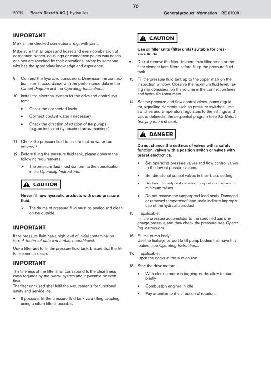
CAUTION
Never fi ll new hydraulic products with used pressure fl uid.
The drums of pressure fl uid must be sealed and clean on the outside.
IMPORTANTIf the pressure fl uid has a high level of initial contamination (see 4 Technical data and ambient conditions):
Use a fi lter unit to fi ll the pressure fl uid tank. Ensure that the fi l-ter element is clean.
IMPORTANTThe fi neness of the fi lter shall correspond to the cleanliness class required by the overall system and if possible be even fi ner.The fi lter unit used shall fulfi l the requirements for functional safety and service life.
• If possible, fi ll the pressure fl uid tank via a fi lling coupling, using a return fi lter if possible.
CAUTION
Use oil fi ller units (fi lter units) suitable for pres-sure fl uids.
• Do not remove the fi lter strainers from fi ller necks or the fi lter element from fi lters before fi lling the pressure fl uid tank.
13. Fill the pressure fl uid tank up to the upper mark on the inspection window. Observe the maximum fl uid level, tak-ing into consideration the volume in the connection lines and hydraulic consumers.
14. Set the pressure and fl ow control valves, pump regula-tor, signalling elements such as pressure switches, limit switches and temperature regulators to the settings and values defi ned in the sequential program (see 9.2 Before bringing into fi rst use).
DANGER
Do not change the settings of valves with a safety function, valves with a position switch or valves with preset electronics.
• Set operating-pressure valves and fl ow control valves to the lowest possible values.
• Set directional control valves to their basic setting.
• Reduce the setpoint values of proportional valves to minimum values.
• Do not remove the tamperproof lead seals. Damaged or removed tamperproof lead seals indicate improper use of the hydraulic product.
15. If applicable:Fill the pressure accumulator to the specifi ed gas pre-charge pressure and then check the pressure, see Operat-ing Instructions.
16. Fill the pump body:Use the leakage oil port to fi ll pump bodies that have this feature, see Operating Instructions.
17. If applicable:Open the cocks in the suction line.
18. Start the drive motors:
• With electric motor in jogging mode, allow to start briefl y
• Combustion engines in idle
• Pay attention to the direction of rotation.
70
Hydraulics Bosch Rexroth AGRE 07008 General product information 21/32
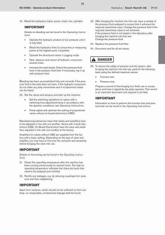
19. Bleed the hydraulics (valve, pump, motor, line, cylinder).
IMPORTANTDetails on bleeding can be found in the Operating Instruc-tions.
• Operate the hydraulic product at low pressure until it is fully bled.
• Bleed the hydraulics lines to consumers or measuring points at the highest point, if possible.
• Operate the directional valves in jogging mode.
• Next, advance and retract all hydraulic consumers several times.
• Increase the load slowly. Check the pressure fl uid level in the pressure fl uid tank. If necessary, top it up with pressure fl uid.
Bleeding has been accomplished fully and correctly if the pres-sure fl uid in the tank does not foam, if the hydraulic consumers do not make any jerky movements and if no abnormal noises can be heard.
20. Set the valves and sensors and start up the machine:
• Set the switching operations of valves with a switching time adjustment/ramp in accordance with the dynamic conditions, see Operating Instructions.
• Finely adjust and optimise the setting of proportional valves without on-board electronics (OBE).
Manufacturing tolerances mean that valves and amplifi ers have to be adjusted in line with one another. Valves with in-built elec-tronics (OBE, On Board Electronics) have the valve and ampli-fi ers adjusted in line with one another at the factory.
Amplifi ers for valves without OBE are supplied from the fac-tory with a basic setting. Depending on the type of valve and amplifi er, you may have to fi ne-tune the null point and sensitivity before bringing the valve into use.
IMPORTANTDetails on fi ne-tuning can be found in the Operating Instruc-tions.
21. Check the operating temperature after the machine has been running continuously for several hours. Too high an operating temperature indicates that there are faults that need to be analysed and rectifi ed.
22. Rectify any leakages, e.g. by relieving couplings from pres-sure and then retightening.
IMPORTANTApart from moisture, which should not be suffi cient to form one drop, no measurable, unintentional leakage shall be found.
23. After bringing the machine into fi rst use, have a sample of the pressure fl uid analysed to ensure that it achieves the required cleanliness class. Change the pressure fl uid if the required cleanliness class is not achieved.If the pressure fl uid is not tested in the laboratory after bringing the machine into fi rst use: Change the pressure fl uid.
24. Replace the pressure fl uid fi lter.
25. Document and fi le all set values.
DANGER
26. To ensure the safety of persons and the system, after bringing the machine into fi rst use, perform the following tests using the defi ned maximum values:
• Function test
• Pressure test.
Prepare a record of the bringing into (fi rst) use or accep-tance and have it signed by the plant operator. This record is an important document and requires to be fi led.
IMPORTANTInformation on how to perform the function test and pres-sure test can be found in the Operating Instructions.
71
1
22/32 Bosch Rexroth AG Hydraulics General product information RE 07008
10 Operation
IMPORTANTPlease refer to the Operating Instructions for all information on how to operate the Rexroth hydraulic product.
11 Trouble-shooting
11.1 What to do in the event of a fault
DANGER
In the event of abnormal occurrences or malfunctions, stop all work on the Rexroth hydraulic product immediately and inform the responsible personnel.
IMPORTANTA table for product-specifi c trouble-shooting can be found in the Operating Instructions.
If the responsible personnel are unable to rectify the problem immediately:
• Switch off the main switch. If applicable, turn off any combustion engines used as drive motors.
• Secure the main switch against being unintentionally switched on again.
• Inform the machine manufacturer.
11.2 The basic approach to trouble-shooting
The information in this section is intended to help you create the ideal conditions for carrying out trouble-shooting as effi -ciently as possible.
11.2.1 General conditions
Is all the necessary technical documentation to hand?
If no hydraulic circuit diagram is available:Can a hydraulic circuit diagram be drawn using the struc-ture, signs and labelling of the equipment?
Are there enough measuring points?
Has the customer provided useful information about how the malfunction manifests itself and about the functional behaviour of the system/component prior to the malfunc-tion?
Is there a machine record book that may document similar malfunctions in the past?
11.2.2 Recommended way of working when trouble-shooting
Successful trouble-shooting for a hydraulic product requires precise knowledge about the structure and method of opera-tion of the individual components. Where hydraulics are combined with electrics/electronics, in particular, trouble-shooting is rendered more diffi cult and co-operation between electricians and hydraulic specialists is required.
• Even if you are under time pressure, proceed systemati-cally and methodically.Indiscriminate, hasty dismantling and readjustments may, in the worst case, result in the original cause of failure being impossible to determine.
• Make sure that you gain an overview of the function of the hydraulics in respect of the overall system in which the hydraulics are installed.
• Try to fi nd out whether the hydraulics performed the required function in the overall system prior to the occurrence of the fault.
• Try to determine any modifi cations to the overall system in which the hydraulics are installed:
Have the operating conditions or operating range of the hydraulics been changed?
Have modifi cations (e.g. retrofi tted equipment) or repairs been carried out on the overall system (machine/system, electrics, control system) or on the hydraulics? If yes: What were they?
Have the set values of the hydraulics been changed?
Have the hydraulics recently undergone mainte-nance?
Has the hydraulic product/machine been operated improperly?
How does the malfunction manifest itself?
• Form a clear picture of the cause of the fault. Ask the machine operators directly, if necessary.
• Document any work undertaken, changed set values, etc.
• Document any amendments/additional information that should be included in the Operating Instructions.
72
Hydraulics Bosch Rexroth AGRE 07008 General product information 23/32
11.2.3 Systematic trouble-shooting procedure
Is there an inspection and maintenance book which might provide information about the trend of test parameters (e.g. temperature of hydraulic fl uid, replacement intervals of fi lter elements, noises)?
Have there been any identical or similar failures in the past?
• Make a note of causes of failures with a low probability. Only investigate the failure causes you have noted down if all failure causes with a high probability have been proven to be inapplicable.
• Draw up a list of priorities of the most probable failure causes.
• Verify these listed failure causes one after the other (by means of theoretical conclusions, disassembly, measurements or tests).
• Document the causes of failure you have discovered, and note down how you discovered them.
11.3 Trouble-shooting tables
IMPORTANTThe causes of failure in hydraulic systems can be extremely complex. Therefore, general rules for trouble-shooting can only be laid down to a limited degree.
Please refer to the relevant Operating Instructions for product specifi c information about trouble-shooting the Rexroth hydrau-lic product.
73
1
24/32 Bosch Rexroth AG Hydraulics General product information RE 07008
12 Maintenance
12.1 Defi nitions of terms
The term Maintenance as defi ned in DIN 31051 encompasses all measures to maintain and restore the desired conditions and to determine and assess the actual condition of the techni-cal devices of a system .
These measures are divided into the following categories:
Inspection (determining the actual condition)
Servicing (maintaining the desired condition)
Repair (restoring the desired condition).
The above measures include:
Adapting maintenance objectives to suit company objec-tives
Determining appropriate maintenance strategies.
12.2 Safety during maintenance tasks
DANGER
In the interests of safety, please observe all the following safety instructions carefully and at all times.
• Check safety devices regularly to see that they are working properly.
• Perform all maintenance work properly, completely and within the stipulated periods and make a record of the work.
• Inform all personnel before commencing maintenance work.
• Generously cordon off the maintenance zone before commencing work.
• Inform all persons of ongoing maintenance work by means of the appropriate signs. In particular, attach warning signs to the control cabinet, main switch, actuators and points of access.
If you have to switch off the hydraulic product, secure it against being unintentionally switched on again as follows:
• Switch off all drives, disconnect the hydraulics from the mains at the main switch.
• Depressurise the hydraulic product (relieve any pressure accumulators of pressure).
• Secure the main switch against being unintentionally switched on again.
Before undertaking any manual intervention in the Rexroth hydraulic product:
DANGER
Please refer to the Operating Instructions for all the neces-sary information on depressurisation and on those parts of the Rexroth hydraulic product that are not depressurised automatically.
• Advance all cylinders to their safe end position.
• Lower all loads.
• Switch off all pumps.
• Mechanically support vertical cylinders so that they cannot drop. Never perform any maintenance work on raised units without external support.
• Relieve any accumulators of pressure in the proper manner.
• Switch off the pressure supply and secure the hydraulic product against being inadvertently switched on again.
• Ensure that only authorised personnel remain in the work zone.
• Wear safety glasses, gloves and boots.
• Allow pressure lines and sections of the system which have to be opened to cool down before commencing maintenance work.
• Open with care any segments that have to remain under pressure.
Since check valves are located in the pressure lines above the pumps, the hydraulic system may still be under pressure even after it has been disconnected from the actual pressure supply.
Certain segments, such as servo cylinders, also continue to remain under pressure because the proportional valves remain in the closed position (all valves are illustrated in their basic position in the hydraulics diagram).
Observe the following:
Only new, interchangeable and tested components, replacement parts and lubricants in original-equipment quality are approved for use/replacement.
For reasons of safety, the installation of used and/or untested components is strictly prohibited and leads to loss of EU Conformity.
Exercise extreme vigilance when operating the hydraulic prod-uct in maintenance mode, which may in certain circumstances necessitate the temporary removal of certain safety devices.
74
Hydraulics Bosch Rexroth AGRE 07008 General product information 25/32
Make sure that all safety devices are properly installed and have undergone a function test before bringing the system (back) into use.
• Perform welding, burning or grinding work on the hydraulic unit or its attachments only with the approval of local safety authorities/fi re brigade and with suitable protective covering to prevent ingress of contaminants.
• When performing assembly work above your height, use the steps and platforms provided by the plant operator. Do not climb on any parts of the system.
• Remove all tools and materials needed for maintenance from the hydraulic product.
• Always rectify any leakage from the hydraulic product immediately.
• Always inform personnel before (re)starting the hydraulic product.
12.3 Inspection and servicing
The objective of inspection and servicing is
To maintain all system functions along with the initial parameters of the system
To ensure continual availability of the system
To detect weak points
To ensure that the system attains the required service life.
IMPORTANTThe following general specifi cations are based on use of the hydraulic product in central Europe and under the usual operat-ing conditions of commercial and industrial plants.
We strongly recommend the use of an inspection and servicing book, in which all work specifi c to that site, and all inspection and servicing intervals should be defi ned and documented.
An inspection and servicing book is also helpful in that
It provides comparison values to aid with early detection of malfunctions
It allows warranty claims to be dealt with more easily.
CAUTION
Ensure cleanliness during all work.
• Please observe the requirements for pressure fl uids mentioned in Section 9 Assembly and bringing into fi rst use.
• Clean the external environment of couplings/joints and devices before disassembly. Do not use cleaning wool or cloths containing fi bres for cleaning.
• Seal all openings using protective caps.
• Bleed the hydraulic product after each item of servicing
work.
• Document and fi le details of any work undertaken, changed set values, etc.
• Document and fi le details of any amendments/additional information that should be included in the Operating Instructions.
• Modifi cations and additions could affect the validity of the EU Conformity Declaration/Manufacturer’s Declaration. Always consult Bosch Rexroth about any proposed modifi cations or additions.
75
1

26/32 Bosch Rexroth AG Hydraulics General product information RE 07008
12.3.1 Inspection procedures and test equipment, general
The following are some of the typical inspection and testing procedures that are regularly used in connection with hydraulic systems and components.
IMPORTANTKeep the indicated typical test equipment ready for this type of work.
Type of test Typical test equipment
Typicaltesting activities
Pressure measure-ment
Pressure gauge or sensor with suitable measuring range and connec-tion pipe and con-nection coupling
Checking of
• specified pressure
• opening pressure
• pressure difference before and after the object under test
Visual inspection
– Checks for
• all components securely seated
• damage
• wear
• leakage (formation of oil droplets)
• presence of all warning and informative signs
Touch inspection
– Checks for
• unusual local vibrations
Temperature inspection
Temperature measuring instrument
Checks for
• unusual local temperature zones
Acoustic inspection
– Checks for
• changes in running noise of the unit
• changes in flow noise
• changes in operating noise in the unit and valve control.
12.3.2 Location of testing and measuring points
IMPORTANTPlease refer to the Operating Instructions for the installation location of fi lling level indicators, fi lling points, drainage points, fi lters, testing points, strainers, solenoids, etc. that require reg-ular inspection and servicing.
12.3.3 Inspection and servicing plan, hydraulic products, general
The graph illustrates the concept of wear/wear margin. The wear margin is a characteristic feature used to describe the condition of the system for the purpose of maintenance.
100%
0tst0 ti1 ti2
Z0
1
4
23
6
5
1 Wear margin Z02 Time t
3 Repair (corrective maintenance) time (ti2 – ti1)
4 Damage threshold (damage time tS)5 Desired condition after corrective maintenance
6 Failure
The reduction in the wear margin refl ects wear. The curve rep-resents one possible form of the wear profi le during the period of use. It is determined during inspection and varies depend-ing, fi rstly, on the system itself (e.g. material selection, sur-face treatment, quality) and secondly on external infl uences or boundary conditions such as servicing levels, corrosive cir-culating air and dust. Thirdly, it depends on how the system is operated; whether with partial load or partially with excess load, whether it is subject to surge loads or steady load, etc. Where hydraulic systems are concerned, the curve is also infl u-enced by the cleanliness class and degree of fouling of the pressure fl uid, the number of cycles and the ambient condi-tions.
76
Hydraulics Bosch Rexroth AGRE 07008 General product information 27/32
All the factors mentioned above can exert an infl uence on the curve but this need not necessarily adversely affect the quality of its information, as wear always signifi es the reduction in the wear margin, which is understood to be the primary initial vari-able before wear commences.
Consequently, this means that a sudden change in the wear margin must also count as wear, and that the element of time on its own is not of decisive importance for wear, but is of con-siderable interest in the assessment and evaluation of such wear.
An increase in the wear margin to over 100 % above its base-line may be achieved through corrective maintenance, if such measures entail an improvement and this increase is estab-lished as the new desired condition for future corrective main-tenance.
Certain system parts may be subject to a wear margin which diminishes in such a way that the time available for use is insuf-fi cient for the requirements of the plant or operation. In this case, investigations must be carried out to ascertain whether the introduction of suitable technical measures might counter this reduction in the wear margin to a satisfactory extent. The time and expenditure required for such measures must natu-rally be kept in reasonable proportion to the expected degree of success.
If such conditions arise, we refer to these parts as weak points. Since their elimination may provide economic and safety advantages, weak points require to be rectifi ed immediately.
IMPORTANTThe inspection and servicing plan for your particular product can be found in the Operating Instructions.
12.3.4 Inspection and servicing plan, electrohydraulic systems
Electrohydraulic systems with proportional valves must be ser-viced in accordance with hydraulic requirements and strate-gies. However, technical control components must also be incorporated in these servicing cycles.
On this basis, an overall strategy for system servicing must be developed and documented.
IMPORTANTThe appropriate component characteristics relevant to servic-ing can be found in the Operating Instructions.
12.3.5 Inspection and servicing plan: electrics and control system
IMPORTANTThe product-specifi c inspection and servicing plan for electrics and control systems can be found in the Operating Instruc-tions.
12.3.6 Lubrication points, lubricants, intervals
IMPORTANTThe details of the specifi ed lubricants, lubrication points and associated lubrication cycles can be found in the Operating Instructions.
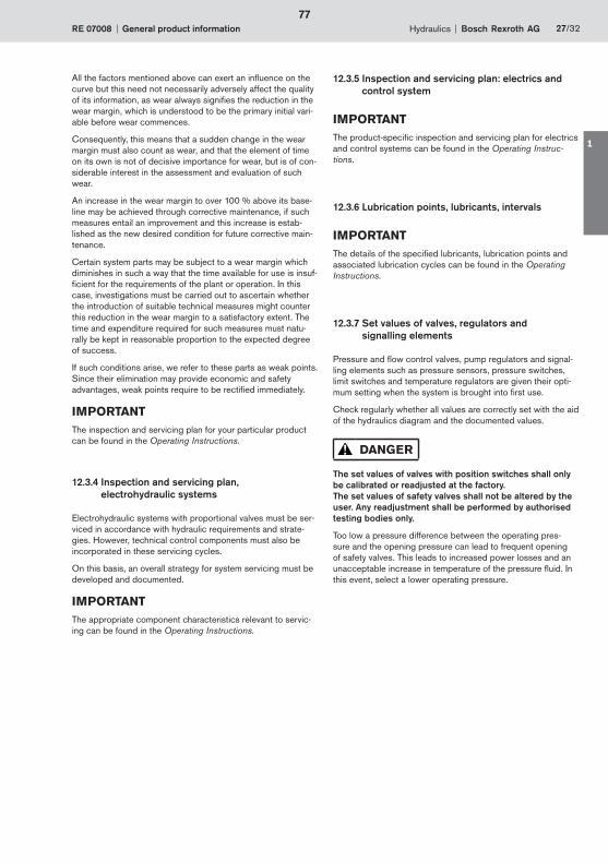
12.3.7 Set values of valves, regulators and signalling elements
Pressure and fl ow control valves, pump regulators and signal-ling elements such as pressure sensors, pressure switches, limit switches and temperature regulators are given their opti-mum setting when the system is brought into fi rst use.
Check regularly whether all values are correctly set with the aid of the hydraulics diagram and the documented values.
DANGER
The set values of valves with position switches shall only be calibrated or readjusted at the factory. The set values of safety valves shall not be altered by the user. Any readjustment shall be performed by authorised testing bodies only.
Too low a pressure difference between the operating pres-sure and the opening pressure can lead to frequent opening of safety valves. This leads to increased power losses and an unacceptable increase in temperature of the pressure fl uid. In this event, select a lower operating pressure.
77
1
28/32 Bosch Rexroth AG Hydraulics General product information RE 07008
12.3.8 Replacement of pressure fl uid fi lters and ventilation fi lters
CAUTION
Unfi ltered pressure fl uid fi lters lead to increased wear of all the system’s hydraulic products and can cause func-tional failures with dangerous effects. Therefore, always replace contaminated oil fi lters immediately.
Clogged ventilation fi lters result in inadequate cooling and can therefore cause excessive heating up and malfunc-tions of the hydraulic system. Therefore, always replace contaminated ventilation fi lters immediately.
• Clogged fi lters must always be replaced immediately. Do not clean clogged fi lters.
• Allow the contents of the replaced oil fi lter to drip and fully drain.
• Dispose of the fi lter in accordance with the applicable regulations.
Exact instructions on how to replace a fi lter can be found in the Filter manufacturer’s instructions for use.
12.3.9 Checking fi lters with a contamination indicator
Filters with contamination indicators continuously measure the degree of fouling. The dirt-retention capacity of the fi lter is uti-lized to the full.
IMPORTANTCheck the contamination indicator when the pressure fl uid is warm (during or immediately after operation).
If the ambient temperature is low or the pressure fl uid is cold, its high viscosity may cause clogging to be indicated, although the pressure fl uid is in fact clean.
Procedure:
1. Wait until the hydraulic product has reached operating temperature.
2. Press the indicator button (check function):If the indicator button pops out again immediately, the fi lter must be replaced by the end of the shift at the latest.
Due to the progressive loss in pressure as the fi lter becomes increasingly contaminated, the indicator point has a certain reserve capacity, i.e. generally suffi cient for a work shift of 8 h.
If the fi lter is not replaced after 8 h, dirt may penetrate the sys-tem, resulting in contamination of the hydraulic product.
CAUTION
In certain circumstances the contamination indicator does not show a required fi lter replacement.
If the check function never indicates fi lter replacement and the contamination indicator is functioning correctly, this may have the following causes:
Faulty fi lter
A bypass valve may have been installed and is not closing correctly, e.g. due to the entry of dirt particles.
12.4 Service and storage lives of hose lines
IMPORTANTIn terms of the service life of hydraulic hose lines in these Operating Instructions, replacement and storage lives are mea-sured from the date of manufacture of the hose line.
Even when properly stored and subjected to permissible loads, seals, hoses and hose lines undergo a natural ageing process.
The replacement and storage lives of seals, hoses and hose lines are therefore limited (see 8.2 Seals, hoses and hose lines).
DANGER
Hose lines must be replaced in accordance with the provi-sions of the servicing plan, even if there are no detectable technical defects in the hose line.
Hoses that have already been used as part of a hose line shall not be reused in a hose line.
The fi rst use may have changed the properties of the hose material to such an extent that reuse of the hose repre-sents a very high risk.
78

Hydraulics Bosch Rexroth AGRE 07008 General product information 29/32
12.5 Topping up the pressure fl uid
IMPORTANTOnly pressure fl uids specifi ed in the Operating Instructions are to be used.
When changing or topping up the pressure fl uid, fi ll the pres-sure fl uid tank on the hydraulic product as follows:
1. Fill the pressure fl uid tank using a special fi lling unit with an integral fi lter (min. 10 μm).
2. Drop the system pressure right down by resetting the pump. Set the pressure setting value on the pump pres-sure control to minimum or zero pressure.
3. Fill and bleed the line system of the hydraulic product from the unit to the cylinder. To do this actuate the cylinder in both directions, see Operating Instructions.
4. Top up the pressure fl uid volume to the specifi ed quantity.
5. Raise the pump pressure to the system pressure.
The hydraulic product is ready for operation.
6. Carry out a test run.
7. Check the level of the fl uid after the hydraulic product has warmed up to the operating temperature and adjust if nec-essary.
IMPORTANTCheck the contamination indicator when the pressure fl uid is warm (during or immediately after operation).
If the ambient temperature is low or the pressure fl uid is cold, its high viscosity may cause clogging to be apparently indi-cated.
12.6 Servicing pressure accumulators
DANGER
Pressure accumulators are subject to the national legisla-tion on safety requirements for pressure vessels applica-ble in the place of installation.
Observe the Pressure Equipment Directive 97/23/EC.
IMPORTANTThe gas precharge pressure is measured with a testing and fi ll-ing device.
Details of the procedure can be found in the Operating Instruc-tions.
Inspection and servicing
• Carry out the tests required by law.
• Test and monitor the gas precharge pressure regularly.
12.7 Repair
IMPORTANTRepair (corrective maintenance) is the restoring of the desired condition.
In addition, observe the special safety instructions in12 Maintenance and the safety instructions in the Operating Instructions.
DANGER
Ensure cleanliness during all work.
• Clean the external environment of couplings/joints and devices before disassembly. Do not use cleaning wool or cloths containing fi bres for cleaning.
• Seal all openings using protective caps.
• Bleed the hydraulic product after each item of repair work.
• If appropriate, follow the procedure for bringing into fi rst use, see 9.3 Bringing into fi rst use, subsequent bringing into use.
• Document any amendments/additional information that should be included in the Operating Instructions.
79
1
30/32 Bosch Rexroth AG Hydraulics General product information RE 07008
12.7.1 General safety instructions for repair work
DANGER
Repair work shall only be done by an authorised hydraulics expert who has the required specialist hydraulics knowl-edge.
Specialist hydraulics knowledge means, among other things, that the person can read and fully understand hydraulics draw-ings. In particular, he must fully comprehend the range of func-tions of the integrated safety components.
Components may only be dismantled for the purpose of repair to the extent described in the Operating Instructions.
Never repair a defective safety valve. It must be completely replaced.
Faulty parts may only be replaced by new, interchangeable, tested components in original-equipment quality. Any devia-tions from this can be found in the Operating Instructions.
Before each subsequent bringing into use after repair work, the hydraulic product shall be accepted by a hydraulics expert.
The operator of the hydraulic product is required to check by means of a servicing record that the inspection and servicing plan as been complied with.
Pressure vessels have to be pressure tested every 10 years and the information recorded in accordance with the Pressure Equipment Directive 97/23/EC or its implementation in national legislation.
13 General information about hydraulic pressure accumulators
13.1 General
The regulations applicable at the place of installation concern-ing hydraulic pressure accumulators (hydrostatic accumula-tors) must be observed before bringing into use and during operation.
The plant operator bears sole responsibility for compliance with the existing regulations.
Hydrostatic accumulators are subject to the national implemen-tation of the EU Pressure Equipment Directive 97/23/EC.
Documents supplied with accumulators must be preserved with care; they will be required during recurring inspections by specialists.
The bringing into use of hydrostatic accumulators shall be car-ried out by trained expert personnel only.
WARNING
Do not perform any welding, soldering or mechanical work on accumulator vessels.
Welding and soldering carry a risk of explosion!
Mechanical tampering may cause the vessel to burst and the operating permit will be withdrawn.
Do not charge hydrostatic accumulators with oxygen or air. Risk of explosion!
Depressurise the system before working on hydraulic installations.
Improper installation can lead to serious damage to per-sons and property.
13.2 Safety devices relating to hydraulic pressure accumulators
The equipping, installation and operation of hydrostatic accu-mulators is regulated by the national implementation of the EU Pressure Equipment Directive 97/23/EC and additionally in the Federal Republic of Germany by the Technical Regulations for Pressure Vessels (TRB). This legislation requires the following safety equipment:
Device to protect against excessive pressure (prototype-tested)
Pressure relief device
Pressure measuring device
Test gauge connection
Shut-off device
Optional: electromagnetically operated pressure relief device
Safety device to protect against overheating.
IMPORTANTSee the Operating Instructions.
80
Hydraulics Bosch Rexroth AGRE 07008 General product information 31/32
14 Hydraulic systems
Hydraulic systems are generally intended for installation in machines or systems. In addition to the basic information about the installed components, the information contained in the Operating Instructions made available for each hydraulic sys-tem by Bosch Rexroth also applies to hydraulic systems.
By installing the hydraulic system in a machine or system, the interaction of the hydraulic system with the overall machine may give rise to changes in the potential dangers. In particular the effect of hydraulic and electrical control of hydraulic drives that create mechanical movement are to be considered.
This information shall be included in the hazard analysis/risk assessment of the overall machine carried out by its supplier and in the Operating Instructions of the overall machine. This also applies to the specifi cation of the interfaces between the hydraulic system and the overall machine.
Hydraulic systems are subject to legislation including the Pres-sure Equipment Directive and other relevant EU directives that have been implemented in national legislation. Exact informa-tion can be found in the EU Conformity Declaration or Manu-facturer’s Declaration that is supplied with the hydraulic system or the hydraulic product.
WARNING
Before installing a hydraulic system in a machine or mod-ifying an existing hydraulic system in a machine, satisfy yourself that
the hydraulic system is suitable for its application in the machine
the ambient conditions in the machine are suitable and/or permissible for the use of the hydraulic system
other installed items on or in the machine cannot disturb or endanger the functioning or the safe operation of the hydraulic system.
If the overall machine is to be used in a potentially explosive atmosphere, then it must be ensured that the hydraulic system has been designed and is suitable for this use.
14.1 Effects of leaks in the hydraulic system on the machine
If pressure fl uid escapes from the hydraulic system and comes into contact with hot surfaces on the machine, this can lead to the generation of life-threatening smoke, fi re and/or other dan-gerous operating conditions.
These risks shall be determined by the machine manufacturer by means of a hazard analysis and if necessary provision made for the appropriate safety devices.
81
1
32/32 Bosch Rexroth AG Hydraulics General product information RE 07008
Bosch Rexroth AGHydraulicsZum Eisengiesser 197816 Lohr am Main, GermanyTel. + 49 (0) 93 52 / 18-0Fax + 49 (0) 93 52 / 18-23 [email protected]
© All rights reserved, Bosch Rexroth AG, including applications for intellec-tual property rights. We reserve all power of disposal, rights of reproduction and issue.
The data specifi ed above only serve to describe the product. No statements concerning a certain condition or suitability for a certain application can be derived from our information. The given information does not release the user from the obligation of own judgement and verifi cation. It must be remembered that our products are subject to a natural process of wear and aging.
DE Bestellinformation für deutsche Produktinformation: RD 07008
EN Ordering Information for Product Information in English: RE 07008
FR Information de commande pour la notice française Informations générales sur les produits : RF 07008
IT Informazioni d’ordine per le informazioni tedesche sul prodotto: RI 07008
ES Información para el pedido de la información del producto en español: RS 07008
FI Tilaustiedot - suomenkieliset tuotetiedot: RSF 07008
NL Bestelinformatie voor Nederlandse productinformatie: RNL 07008
SV Beställningsnummer för svensk produktinformation: RSK 07008
PT Informação dos dados de encomenda para informação de produto alemã: RP 07008
DA Bestillingsinformationer vedr. dansk produktinformation: RDK 07008
EL Πληρ�φ�ρίερ παραγγελίαρ για τιρ γερμανικέρ πληρ�φ�ρίερ πρ�ϊϋντ�ρ: RGR 07008
http://www.boschrexroth.com/bri-products → Datenblatt-Suche/Datasheet search → Suche nach Datenblatt/Search by datasheet
07008
82

1/6Installation, commissioning and maintenance of hydraulic systems
RE 07900/10.06Replaces: 08.06
1. General
1.1 Long service life and functional reliability of hydraulic systems and their components depend on correct handling.
Ensure trouble-free operation by observing the following points:
– The specific installation and operating instructions for the relevant components
– Special instructions in individual cases
– Technical data in the data sheet.
In addition, we would like to draw your attention to the fol- lowing regulations:
– German standard “Hydraulic systems“ DIN 24346
– ISO standard ISO 4413
2. Installation
2.1 Preparatory work for the installation
– Sauberkeit der Anlage gewährleisten!
• For the surroundings:
Keep power units, line connections and components clean or clean them (e.g. pickling after, for example, pro- cesses have been carried out that involve heat, i.e. wel- ding, hot bending, etc.)!
• For hydraulics fluids:
Take care of contamination and humidity; contamination from the environment must not enter the tanks! Fill oil tanks only through filters, preferably system filters or portable filter stations with fine filters. Internal protective coatings, if any, must be resistant to the hydraulic fluid used!
• For parts taken from stock:
The storage of parts that were not filled or treated with anti-corrosion fluid can lead to the formation of resin. Solve the resin using a grease solvent and renew the lubricating film.
– Check to see that all of the parts required for the installa- tion are available!
– Take note of any transport damage!
2.2 Carrying out the montage
– Use lifting lugs and transport facilities!
– Do not apply force to prevent transverse forces and tensi- on on pipes and components. The valve mounting sur- faces must be perfectly even. The fixing screws must be tightened evenly at the specified torque.
Take care that pipes are adequately fixed!
– When selecting pipes, hoses and fittings/flanges, obser- ve the correct pressure stage (wall thickness, material). Use only seamless precision steel pipes.
83
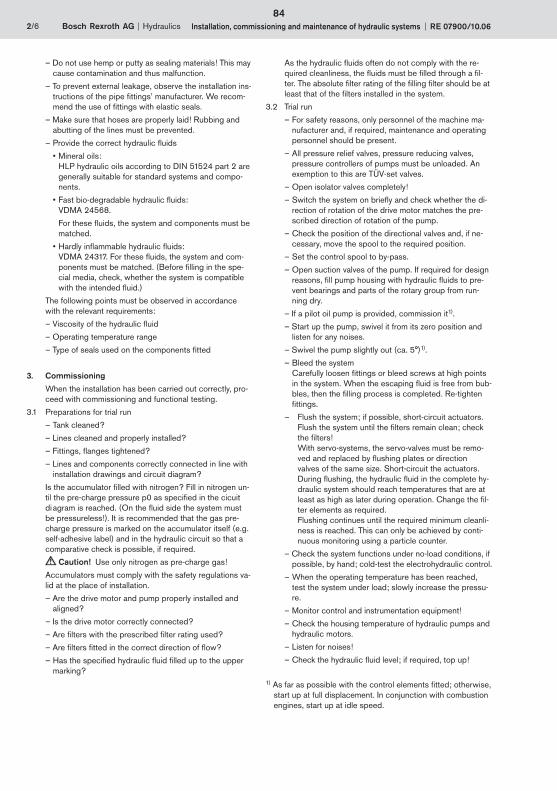
2/6 Bosch Rexroth AG Hydraulics Installation, commissioning and maintenance of hydraulic systems RE 07900/10.06
– Do not use hemp or putty as sealing materials! This may cause contamination and thus malfunction.
– To prevent external leakage, observe the installation ins- tructions of the pipe fittings’ manufacturer. We recom- mend the use of fittings with elastic seals.
– Make sure that hoses are properly laid! Rubbing and abutting of the lines must be prevented.
– Provide the correct hydraulic fluids
• Mineral oils: HLP hydraulic oils according to DIN 51524 part 2 are generally suitable for standard systems and compo- nents.
• Fast bio-degradable hydraulic fluids: VDMA 24568.
For these fluids, the system and components must be matched.
• Hardly inflammable hydraulic fluids: VDMA 24317. For these fluids, the system and com- ponents must be matched. (Before filling in the spe- cial media, check, whether the system is compatible with the intended fluid.)
The following points must be observed in accordance with the relevant requirements:
– Viscosity of the hydraulic fluid
– Operating temperature range
– Type of seals used on the components fitted
3. Commissioning
When the installation has been carried out correctly, pro- ceed with commissioning and functional testing.
3.1 Preparations for trial run
– Tank cleaned?
– Lines cleaned and properly installed?
– Fittings, flanges tightened?
– Lines and components correctly connected in line with installation drawings and circuit diagram?
Is the accumulator filled with nitrogen? Fill in nitrogen un- til the pre-charge pressure p0 as specified in the cicuit di agram is reached. (On the fluid side the system must be pressureless!). It is recommended that the gas pre- charge pressure is marked on the accumulator itself (e.g. self-adhesive label) and in the hydraulic circuit so that a comparative check is possible, if required.
Caution! Use only nitrogen as pre-charge gas!
Accumulators must comply with the safety regulations va- lid at the place of installation.
– Are the drive motor and pump properly installed and aligned?
– Is the drive motor correctly connected?
– Are filters with the prescribed filter rating used?
– Are filters fitted in the correct direction of flow?
– Has the specified hydraulic fluid filled up to the upper marking?
As the hydraulic fluids often do not comply with the re- quired cleanliness, the fluids must be filled through a fil- ter. The absolute filter rating of the filling filter should be at least that of the filters installed in the system.
3.2 Trial run
– For safety reasons, only personnel of the machine ma- nufacturer and, if required, maintenance and operating personnel should be present.
– All pressure relief valves, pressure reducing valves, pressure controllers of pumps must be unloaded. An exemption to this are TÜV-set valves.
– Open isolator valves completely!
– Switch the system on briefly and check whether the di- rection of rotation of the drive motor matches the pre- scribed direction of rotation of the pump.
– Check the position of the directional valves and, if ne- cessary, move the spool to the required position.
– Set the control spool to by-pass.
– Open suction valves of the pump. If required for design reasons, fill pump housing with hydraulic fluids to pre- vent bearings and parts of the rotary group from run- ning dry.
– If a pilot oil pump is provided, commission it1).
– Start up the pump, swivel it from its zero position and listen for any noises.
– Swivel the pump slightly out (ca. 5°)1).
– Bleed the system Carefully loosen fittings or bleed screws at high points in the system. When the escaping fluid is free from bub- bles, then the filling process is completed. Re-tighten fittings.
– Flush the system; if possible, short-circuit actuators. Flush the system until the filters remain clean; check the filters! With servo-systems, the servo-valves must be remo- ved and replaced by flushing plates or direction valves of the same size. Short-circuit the actuators. During flushing, the hydraulic fluid in the complete hy- draulic system should reach temperatures that are at least as high as later during operation. Change the fil- ter elements as required. Flushing continues until the required minimum cleanli- ness is reached. This can only be achieved by conti- nuous monitoring using a particle counter.
– Check the system functions under no-load conditions, if possible, by hand; cold-test the electrohydraulic control.
– When the operating temperature has been reached, test the system under load; slowly increase the pressu- re.
– Monitor control and instrumentation equipment!
– Check the housing temperature of hydraulic pumps and hydraulic motors.
– Listen for noises!
– Check the hydraulic fluid level; if required, top up!
1) As far as possible with the control elements fitted; otherwise, start up at full displacement. In conjunction with combustion engines, start up at idle speed.
84

Hydraulics Bosch Rexroth AGRE 07900/10.06 Installation, commissioning and maintenance of hydraulic systems 3/6
– Check the setting of pressure relief valves by loading or braking the system.
– Inspect the system for leaks.
– Switch off the drive.
– Retighten all fittings, even if there is no evidence of lea- kage.
Caution! Only tighten fittings when the system is depressurised!
– Is the pipe fixing adequate, even under changing pres- sure loads?
– Are the fixing points at the correct positions?
– Are the hoses laid so that they do not chamfer, even un- der pressure load?
– Check the fluid level.
– Test the system for all functions. Compare measured values with the permissible or specified data (pressure, velocity. Adjust further control components).
– Jerky movements indicate, amongst other things, the presence of air in the system. By briefly swivelling the pump in one or both directions with the actuator being loaded or braked, it is possible to eliminate certain air pockets. The system is completely bled when all func- tions are performed jerk-free and smoothly and the sur face of the hydraulic fluid level is free from foam. Expe- rience has shown that foaming should have ceased one hour after start-up at the latest.
– Check the temperature.
– Switch off the drive.
– Remove filter elements (off-line and full-flow filters) and inspect them for residues. Clean filter elements or re- place them, if required. Paper or glass fibre elements cannot be cleaned.
– If further contamination is found, additional flushing is required to prevent premature failure of the system components.
– All the adjustments made are to be recorded in an ac- ceptance report.
3.3 Commissioning of fast running systems
Such system can often not be commissioning using the normal measuring instruments (such as pressure gauges, thermometers, electrical multimeters, etc.) and standard tools. Optimization is also not possible. These systems include, for example, forging presses, plastics injection moulding machines, special machine tools, rolling tools, crane controls, machines with electro- hydraulic closed-loop control systems. Commissioning and optimization of these systems often require more comprehensive measuring equipment to al- low several measurements to be taken at a time (e.g. se- veral pressures, electrical signals, travel, velocities, flows, etc.).
3.4 The most common faults occurring during commissioning
Apart from servicing, commissioning is very decisive for the service life and functional reliability of a hydraulic sys- tem.
For this reason, faults during commissioning must be avo- ided as far as possible.
The most common faults are:
– The fluid tank is not inspected.
– The hydraulic fluid is not filtered before being filled in.
– The installation is not checked before commissioning (subsequent conversion with loss of fluid!).
– System components are not bled.
– Pressure relief valves are set only slightly higher than the operating pressure (closing pressure differential is not observed).
– Pressure controllers of hydraulic pumps are set higher or to the same pressure as the pressure relief valve.
– The flushing time of servo systems is not adhered to.
– Abnormal pump noise is ignored (cavitation, leaking suction lines, too much air in the hydraulic fluid).
– Transversal loads on cylinder piston rods are not obser- ved (installation error!).
– Hydraulic cylinders are not bled (damage to seals!)
– Limit switches are set too low.
– The switching hysteresis of pressure switches is not ta- ken into account when settings are made.
– Hydraulic pump and hydraulic motor housings are not filled with hydraulic fluid prior to commissioning.
– Settings are not documented.
– Adjustment spindles are not secured or sealed.
– Unnecessary personnel present during commissioning of the system.
4. Maintenance
According to DIN 31 051 the term “maintenance” in- cludes the following fields of activity:
– Inspection
Measures to recognise and assess the actual situation, i.e. recognise how and why the so-called wear reserve continues to decrease.
– Maintenance
Measures to preserve the nominal conditions, i.e. to take precautions in order that the reduction in the wear reserve during the useful life is kept as low as possible.
– Repair
Measures to restore the nominal condition, i.e. compen- sate for reduction in performance and restore the wear reserve.
Maintenance measures must be planned and taken in ac- cordance with the operating time, the consequences of a failure and the required availability.
4.1 Inspection
The individual points to be inspected should be summa- rised for a specific system in so-called inspection lists in order that the inspections can be carried out adequately by employees with different qualification levels.
Important points of inspection are:
– Checking the hydraulic fluid level in the tank.
– Checking the heat exchanger (air, water) for effec- tiveness.
85
1

4/6 Bosch Rexroth AG Hydraulics Installation, commissioning and maintenance of hydraulic systems RE 07900/10.06
– Checking the system for external leakage (visual inspec- tion).
– Checking the hydraulic fluid temperature during operati- on.
– Checking pressures
– Amount of leakage
– Checking the cleanliness of the hydraulic fluid
Caution!
Visual inspections can only give an approximation (clou- ding of the hydraulic fluid, darker appearance than at the time of filling, sediments in the fluid tank).
If conventional particle counting is impossible, the fol- lowing three methods can be used for establishing the fluid cleanliness:
• Particle counts using electronic counting and sorting equipment.
• Microscopic examination.
• Gravimetric establishment of solids by means of finest filtration of a certain fluid volume (e.g. 100 ml) and weighing of the filter paper before and after the filtra- tion process. This allows the establishment of the amount of solid particles in mg/l.
– Check the contamination of filters. A visual inspection of deep filters, which are widely used today, is no lon- ger possible.
– Analyse the chemical properties of the hydraulic fluid.
– Check the temperature at points where bearings are lo- cated.
– Check the generation of noise.
– Test performance and velocity.
– Inspect pipes and hoses.
Caution!
Damaged pipes and hoses must be immediately re- placed.
– Inspect accumulator stations.
4.2 Maintenance
In practice, inspection, maintenance and repair work is not as strictly separated as the definitions may suggest. Servicing is often done in conjunction with inspections.
For safety reason, pipe fittings, connections and compo- nents must not be loosened or removed as long as the system is pressurised.
Important service work is:
– Create a maintenance book
We recommend that a maintenance book is created to lay down the parts to be inspected.
– Check the hydraulic fluid level
• continuously during commissioning
• shortly after commissioning
• later, at weekly intervals
– Inspect filters
• during commissioning every two to three hours and, if necessary, replace them.
• daily during the first week and replace them as re- quired.
• After one week, the filters should be cleaned as re- quired.
• Maintenance of suction filters:
Suction filters require particularly thorough servicing. After the running-in period, they must be inspected at least once a week and cleaned, if necessary.
– Service the system fluid
• Maintenance intervals depend on the following opera- ting factors:
- Hydraulic fluid condition (e.g. water in oil, strongly aged oil)
- Operating temperature and oil fill
We recommend that the fluid be changed in depen- dence upon an oil analysis. With systems whose oil is not analysed at regular intervals the fluid should be replaced every 2000 to 4000 operating hours at the latest.
• Drain the system fluid at operating temperature and change it.
• Severely aged or contaminated system fluid cannot be improved by adding new fluid!
• Only fill in oil via filters that have at least the same se- paration capacity as the filters installed in the system, or use a system filter.
• Take samples of the system fluid to have the type, size and amount of particles analysed in the lab. Record the results.
– Check the accumulator for its pre-charge pressure; for this, the accumulator must be depressurised on the flu- id side.
Caution!
Work on systems that include accumulators may only be carried out after the fluid pressure was un- loaded.
Welding or soldering work or any mechanical work on accumulators is not permitted.
Improper repairs can lead to severe accidents. Repairs on hydraulic accumulator may therefore only be carried out by Rexroth Service service personnel.
– The operating temperature must be measured. An in- crease in the operating temperature indicates increa- sing friction and leakage.
– Leakage in the pipework
Leakage, especially with underfloor piping, represents, apart from loss of fluid, a risk for equipment and concre- te floors.
For safety reasons, sealing work on the pipes may only be carried out when the system is depressurised. Lea- kage at points that are sealed with soft seals (O-rings, form seal rings, etc.) cannot be eliminated by tightening as these sealing elements are either destroyed or har- dened. Sealing can only be achieved by replacing the sealing elements.
86

Bosch Rexroth AGHydraulicsZum Eisengießer 197816 Lohr am Main, GermanyTelefon +49 (0) 93 52 / 18-0Telefax +49 (0) 93 52 / 18-23 [email protected]
© This document, as well as the data, specifications and other information set forth in it, are the exclusive property of Bosch Rexroth AG. It may not be reproduced or given to third parties without its consent.The data specified above only serve to describe the product. No state-ments concerning a certain condition or suitability for a certain application can be derived from our information. The information given does not release the user from the obligation of own judgment and verification. It must be remembered that our products are subject to a natural process of wear and aging.
Hydraulics Bosch Rexroth AGRE 07900/10.06 Installation, commissioning and maintenance of hydraulic systems 5/6
– Check main and pilot pressure
• Check interval: One week
• Document pressure corrections in the maintenance book.
• Frequent pressure adjustments indicate, among other things, wear of the pressure relief valve.
4.3 Repair
Locate and eliminate malfunction and damage.
– Fault localisation
A precondition for system repairs is successful, i.e. sys- tematic fault search.
This requires in any case detailed knowledge of the structure and the operating principle of the individual components as well as of the entire system. The req- uired documentation should be available and easily ac- cessible.
The most important measuring instruments (thermome- ter, electrical multimeter, industrial stethoscope, stop watch, rpm counter, etc.) should also be available in the vicinity of the system, especially in the case of large systems.
– Fault correction
When carrying out any work, observe strictest cleanli- ness. Before loosening fittings, clean the surrounding area.
Generally, defective components should not be repaired on site, since for the proper repair, the required tooling and the required cleanliness are usually not given on site. On site, only complete components should be changed whenever possible, in order
• to keep the time for which the opened system is expo- sed to ambient influences to a minimum,
• to keep the fluid loss as low as possible,
• to ensure the shortest possible downtime through the use of overhauled and tested components.
After failed components are located, it is essential to check whether the entire system or parts of the system have been contaminated by broken parts or larger amounts of abraded metal.
4.4 Repair and major overhaul of hydraulic components
Generally, it can be said that only the component manu- facturer can carry out major overhauls in the most effici- ently and reliably (same quality standard, trained person- nel, test facilities, warranty, etc.).
87
1

Bosch Rexroth AGHydraulicsZum Eisengießer 197816 Lohr am Main, GermanyTelefon +49 (0) 93 52 / 18-0Telefax +49 (0) 93 52 / 18-23 [email protected]
© This document, as well as the data, specifications and other information set forth in it, are the exclusive property of Bosch Rexroth AG. It may not be reproduced or given to third parties without its consent.The data specified above only serve to describe the product. No state-ments concerning a certain condition or suitability for a certain application can be derived from our information. The information given does not release the user from the obligation of own judgment and verification. It must be remembered that our products are subject to a natural process of wear and aging.
6/6 Bosch Rexroth AG Hydraulics Installation, commissioning and maintenance of hydraulic systems RE 07900/10.0688
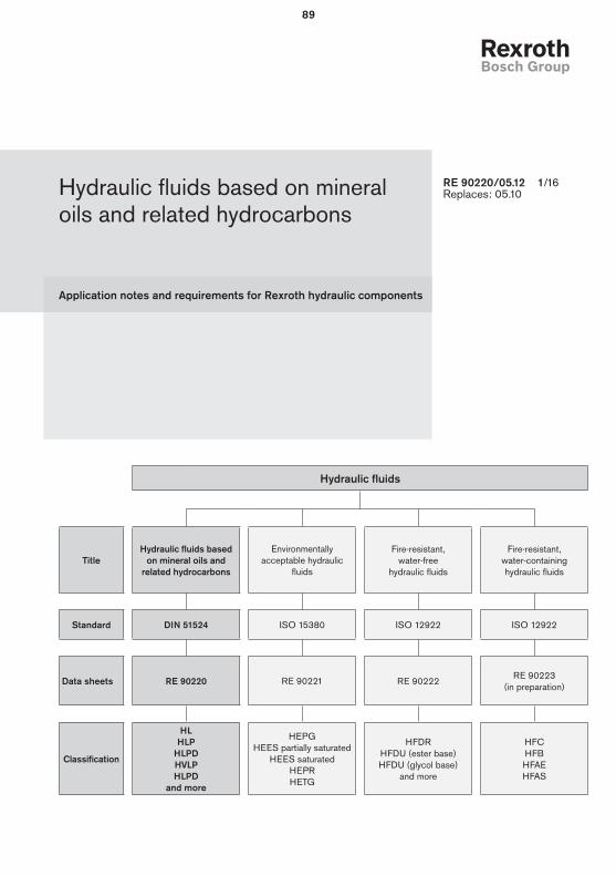
Application notes and requirements for Rexroth hydraulic components
Hydraulic fluids based on mineral oils and related hydrocarbons
RE 90220/05.12 1/16Replaces: 05.10
Hydraulic fluids
TitleHydraulic fluids based
on mineral oils and related hydrocarbons
Environmentally acceptable hydraulic
fluids
Fire-resistant, water-free
hydraulic fluids
Fire-resistant, water-containing hydraulic fluids
Standard DIN 51524 ISO 15380 ISO 12922 ISO 12922
Data sheets RE 90220 RE 90221 RE 90222 RE 90223
(in preparation)
Classification
HLHLP
HLPDHVLPHLPD
and more
HEPGHEES partially saturated
HEES saturatedHEPRHETG
HFDRHFDU (ester base)HFDU (glycol base)
and more
HFCHFBHFAEHFAS
89

2/16 Bosch Rexroth AG Hydraulic fluids based on mineral oils RE 90220/05.12
Contents
1 Basic information .................................................................................................................................................................................................3
1.1 General instructions ...................................................................................................................................................................................3
1.2 Scope ...........................................................................................................................................................................................................3
1.3 Safety instructions .....................................................................................................................................................................................3
2 Solid particle contamination and cleanliness levels ....................................................................................................................................4
3 Selection of the hydraulic fluid ..........................................................................................................................................................................5
3.1 Selection criteria for the hydraulic fluid .................................................................................................................................................5
3.1.1 Viscosity .................................................................................................................................................................................................5
3.1.2 Viscosity-temperature behavior ........................................................................................................................................................5
3.1.3 Wear protection capability ................................................................................................................................................................6
3.1.4 Material compatibility..........................................................................................................................................................................6
3.1.5 Aging resistance .................................................................................................................................................................................6
3.1.6 Air separation ability (ASA) ...............................................................................................................................................................6
3.1.7 Demulsifying ability and water solubility .........................................................................................................................................6
3.1.8 Filterability .............................................................................................................................................................................................6
3.1.9 Corrosion protection ..........................................................................................................................................................................6
3.1.10 Additivation .........................................................................................................................................................................................7
3.2 Classification and fields of application ................................................................................................................................................7
4 Hydraulic fluids in operation ..............................................................................................................................................................................9
4.1 General .........................................................................................................................................................................................................9
4.2 Storage and handling ...............................................................................................................................................................................9
4.3 Filling of new systems...............................................................................................................................................................................9
4.4 Hydraulic fluid changeover ......................................................................................................................................................................9
4.5 Mixing and compatibility of different hydraulic fluids .........................................................................................................................9
4.6 Re-additivation ............................................................................................................................................................................................9
4.7 Foaming behavior .......................................................................................................................................................................................9
4.8 Corrosion ...................................................................................................................................................................................................10
4.9 Air ................................................................................................................................................................................................................10
4.10 Water ........................................................................................................................................................................................................10
4.11 Fluid servicing, fluid analysis and filtration .......................................................................................................................................10
5 Disposal and environmental protection ........................................................................................................................................................11
6 Other hydraulic fluids based on mineral oil and related hydrocarbons .................................................................................................12
7 Glossary ...............................................................................................................................................................................................................15
90
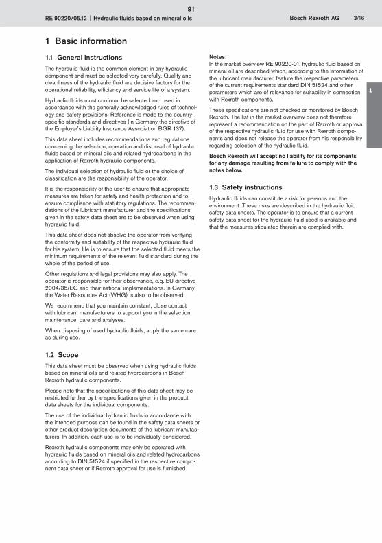
RE 90220/05.12 Hydraulic fluids based on mineral oils Bosch Rexroth AG 3/16
1 Basic information
1.1 General instructionsThe hydraulic fluid is the common element in any hydraulic component and must be selected very carefully. Quality and cleanliness of the hydraulic fluid are decisive factors for the operational reliability, efficiency and service life of a system.
Hydraulic fluids must conform, be selected and used in accordance with the generally acknowledged rules of technol-ogy and safety provisions. Reference is made to the country-specific standards and directives (in Germany the directive of the Employer's Liability Insurance Association BGR 137).
This data sheet includes recommendations and regulations concerning the selection, operation and disposal of hydraulic fluids based on mineral oils and related hydrocarbons in the application of Rexroth hydraulic components.
The individual selection of hydraulic fluid or the choice of classification are the responsibility of the operator.
It is the responsibility of the user to ensure that appropriate measures are taken for safety and health protection and to ensure compliance with statutory regulations. The recommen-dations of the lubricant manufacturer and the specifications given in the safety data sheet are to be observed when using hydraulic fluid.
This data sheet does not absolve the operator from verifying the conformity and suitability of the respective hydraulic fluid for his system. He is to ensure that the selected fluid meets the minimum requirements of the relevant fluid standard during the whole of the period of use.
Other regulations and legal provisions may also apply. The operator is responsible for their observance, e.g. EU directive 2004/35/EG and their national implementations. In Germany the Water Resources Act (WHG) is also to be observed.
We recommend that you maintain constant, close contact with lubricant manufacturers to support you in the selection, maintenance, care and analyses.
When disposing of used hydraulic fluids, apply the same care as during use.
1.2 ScopeThis data sheet must be observed when using hydraulic fluids based on mineral oils and related hydrocarbons in Bosch Rexroth hydraulic components.
Please note that the specifications of this data sheet may be restricted further by the specifications given in the product data sheets for the individual components.
The use of the individual hydraulic fluids in accordance with the intended purpose can be found in the safety data sheets or other product description documents of the lubricant manufac-turers. In addition, each use is to be individually considered.
Rexroth hydraulic components may only be operated with hydraulic fluids based on mineral oils and related hydrocarbons according to DIN 51524 if specified in the respective compo-nent data sheet or if Rexroth approval for use is furnished.
Notes: In the market overview RE 90220-01, hydraulic fluid based on mineral oil are described which, according to the information of the lubricant manufacturer, feature the respective parameters of the current requirements standard DIN 51524 and other parameters which are of relevance for suitability in connection with Rexroth components.
These specifications are not checked or monitored by Bosch Rexroth. The list in the market overview does not therefore represent a recommendation on the part of Rexroth or approval of the respective hydraulic fluid for use with Rexroth compo-nents and does not release the operator from his responsibility regarding selection of the hydraulic fluid.
Bosch Rexroth will accept no liability for its components for any damage resulting from failure to comply with the notes below.
1.3 Safety instructionsHydraulic fluids can constitute a risk for persons and the environment. These risks are described in the hydraulic fluid safety data sheets. The operator is to ensure that a current safety data sheet for the hydraulic fluid used is available and that the measures stipulated therein are complied with.
91
1
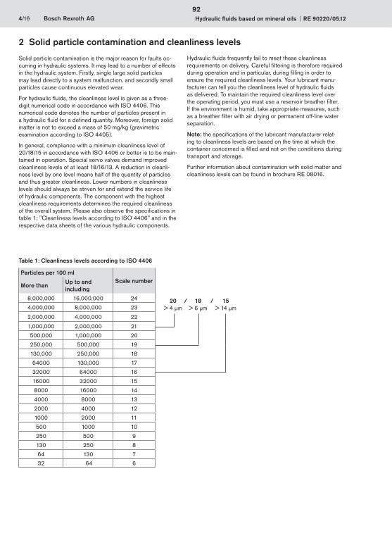
4/16 Bosch Rexroth AG Hydraulic fluids based on mineral oils RE 90220/05.12
2 Solid particle contamination and cleanliness levels
Solid particle contamination is the major reason for faults oc-curring in hydraulic systems. It may lead to a number of effects in the hydraulic system. Firstly, single large solid particles may lead directly to a system malfunction, and secondly small particles cause continuous elevated wear.
For hydraulic fluids, the cleanliness level is given as a three-digit numerical code in accordance with ISO 4406. This numerical code denotes the number of particles present in a hydraulic fluid for a defined quantity. Moreover, foreign solid matter is not to exceed a mass of 50 mg/kg (gravimetric examination according to ISO 4405).
In general, compliance with a minimum cleanliness level of 20/18/15 in accordance with ISO 4406 or better is to be main-tained in operation. Special servo valves demand improved cleanliness levels of at least 18/16/13. A reduction in cleanli-ness level by one level means half of the quantity of particles and thus greater cleanliness. Lower numbers in cleanliness levels should always be striven for and extend the service life of hydraulic components. The component with the highest cleanliness requirements determines the required cleanliness of the overall system. Please also observe the specifications in table 1: "Cleanliness levels according to ISO 4406" and in the respective data sheets of the various hydraulic components.
Hydraulic fluids frequently fail to meet these cleanliness requirements on delivery. Careful filtering is therefore required during operation and in particular, during filling in order to ensure the required cleanliness levels. Your lubricant manu-facturer can tell you the cleanliness level of hydraulic fluids as delivered. To maintain the required cleanliness level over the operating period, you must use a reservoir breather filter. If the environment is humid, take appropriate measures, such as a breather filter with air drying or permanent off-line water separation.
Note: the specifications of the lubricant manufacturer relat-ing to cleanliness levels are based on the time at which the container concerned is filled and not on the conditions during transport and storage.
Further information about contamination with solid matter and cleanliness levels can be found in brochure RE 08016.
Table 1: Cleanliness levels according to ISO 4406
Particles per 100 ml Scale number
More than Up to and including
8,000,000 16,000,000 24
4,000,000 8,000,000 23
2,000,000 4,000,000 22
1,000,000 2,000,000 21
500,000 1,000,000 20
250,000 500,000 19
130,000 250,000 18
64000 130,000 17
32000 64000 16
16000 32000 15
8000 16000 14
4000 8000 13
2000 4000 12
1000 2000 11
500 1000 10
250 500 9
130 250 8
64 130 7
32 64 6
20 / 18 / 15 > 4 μm > 6 μm > 14 μm
92
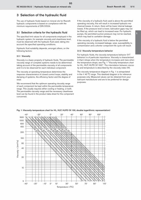
RE 90220/05.12 Hydraulic fluids based on mineral oils Bosch Rexroth AG 5/16
40° 25° 10° 10° 30° 50° 90° 115°70°0°5
10
40
60
20
100
200
400600
1000
1600
VG 100
VG 68
VG 46
VG 32
VG 22
VG 15
VG 10
VG 150
0° 20° 40° 60° 80° 100°40° 20°
3 Selection of the hydraulic fluid
The use of hydraulic fluids based on mineral oils for Rexroth hydraulic components is based on compliance with the minimum requirements of DIN 51524.
3.1 Selection criteria for the hydraulic fluidThe specified limit values for all components employed in the hydraulic system, for example viscosity and cleanliness level, must be observed with the hydraulic fluid used, taking into account the specified operating conditions.
Hydraulic fluid suitability depends, amongst others, on the following factors:
3.1.1 Viscosity
Viscosity is a basic property of hydraulic fluids. The permissible viscosity range of complete systems needs to be determined taking account of the permissible viscosity of all components and it is to be observed for each individual component.
The viscosity at operating temperature determines the response characteristics of closed control loops, stability and damping of systems, the efficiency factor and the degree of wear.
We recommend that the optimum operating viscosity range of each component be kept within the permissible temperature range. This usually requires either cooling or heating, or both. The permissible viscosity range and the necessary cleanliness level can be found in the product data sheet for the component concerned.
If the viscosity of a hydraulic fluid used is above the permitted operating viscosity, this will result in increased hydraulic-me-chanical losses. In return, there will be lower internal leakage losses. If the pressure level is lower, lubrication gaps may not be filled up, which can lead to increased wear. For hydraulic pumps, the permitted suction pressure may not be reached, which may lead to cavitation damage.
If the viscosity of a hydraulic fluid is below the permitted operating viscosity, increased leakage, wear, susceptibility to contamination and a shorter component life cycle will result.
3.1.2 Viscosity-temperature behavior
For hydraulic fluids, the viscosity temperature behavior (V-T behavior) is of particular importance. Viscosity is characterized in that it drops when the temperature increases and rises when the temperature drops; see Fig. 1 "Viscosity temperature chart for HL, HLP, HLPD (VI 100)". The interrelation between viscos-ity and temperature is described by the viscosity index (VI).
The viscosity temperature diagram in Fig. 1 is extrapolated in the < 40 °C range. This idealized diagram is for reference purposes only. Measured values can be obtained from your lubricant manufacturer and are to be preferred for design purposes.
Visc
osity
[
mm
2 /s]
Fig. 1: Viscosity-temperature chart for HL, HLP, HLPD (VI 100, double logarithmic representation)
Temperature t [°C]
93
1
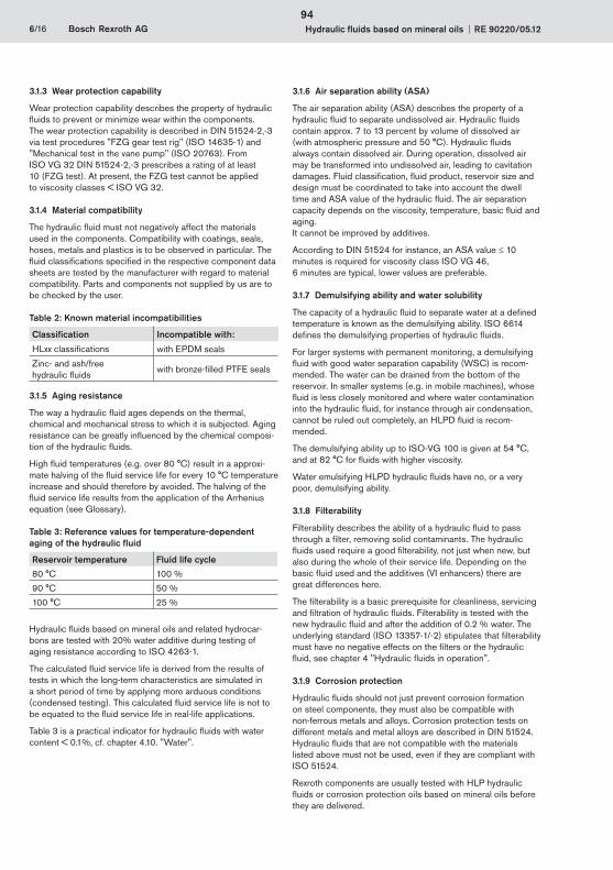
6/16 Bosch Rexroth AG Hydraulic fluids based on mineral oils RE 90220/05.12
3.1.3 Wear protection capability
Wear protection capability describes the property of hydraulic fluids to prevent or minimize wear within the components. The wear protection capability is described in DIN 51524-2,-3 via test procedures "FZG gear test rig" (ISO 14635-1) and "Mechanical test in the vane pump" (ISO 20763). From ISO VG 32 DIN 51524-2,-3 prescribes a rating of at least 10 (FZG test). At present, the FZG test cannot be applied to viscosity classes < ISO VG 32.
3.1.4 Material compatibility
The hydraulic fluid must not negatively affect the materials used in the components. Compatibility with coatings, seals, hoses, metals and plastics is to be observed in particular. The fluid classifications specified in the respective component data sheets are tested by the manufacturer with regard to material compatibility. Parts and components not supplied by us are to be checked by the user.
Table 2: Known material incompatibilities
Classification Incompatible with:
HLxx classifications with EPDM seals
Zinc- and ash/free hydraulic fluids
with bronze-filled PTFE seals
3.1.5 Aging resistance
The way a hydraulic fluid ages depends on the thermal, chemical and mechanical stress to which it is subjected. Aging resistance can be greatly influenced by the chemical composi-tion of the hydraulic fluids.
High fluid temperatures (e.g. over 80 °C) result in a approxi-mate halving of the fluid service life for every 10 °C temperature increase and should therefore by avoided. The halving of the fluid service life results from the application of the Arrhenius equation (see Glossary).
Table 3: Reference values for temperature-dependent aging of the hydraulic fluid
Reservoir temperature Fluid life cycle
80 °C 100 %
90 °C 50 %
100 °C 25 %
Hydraulic fluids based on mineral oils and related hydrocar-bons are tested with 20% water additive during testing of aging resistance according to ISO 4263-1.
The calculated fluid service life is derived from the results of tests in which the long-term characteristics are simulated in a short period of time by applying more arduous conditions (condensed testing). This calculated fluid service life is not to be equated to the fluid service life in real-life applications.
Table 3 is a practical indicator for hydraulic fluids with water content < 0.1%, cf. chapter 4.10. "Water".
3.1.6 Air separation ability (ASA)
The air separation ability (ASA) describes the property of a hydraulic fluid to separate undissolved air. Hydraulic fluids contain approx. 7 to 13 percent by volume of dissolved air (with atmospheric pressure and 50 °C). Hydraulic fluids always contain dissolved air. During operation, dissolved air may be transformed into undissolved air, leading to cavitation damages. Fluid classification, fluid product, reservoir size and design must be coordinated to take into account the dwell time and ASA value of the hydraulic fluid. The air separation capacity depends on the viscosity, temperature, basic fluid and aging. It cannot be improved by additives.
According to DIN 51524 for instance, an ASA value 10 minutes is required for viscosity class ISO VG 46, 6 minutes are typical, lower values are preferable.
3.1.7 Demulsifying ability and water solubility
The capacity of a hydraulic fluid to separate water at a defined temperature is known as the demulsifying ability. ISO 6614 defines the demulsifying properties of hydraulic fluids.
For larger systems with permanent monitoring, a demulsifying fluid with good water separation capability (WSC) is recom-mended. The water can be drained from the bottom of the reservoir. In smaller systems (e.g. in mobile machines), whose fluid is less closely monitored and where water contamination into the hydraulic fluid, for instance through air condensation, cannot be ruled out completely, an HLPD fluid is recom-mended.
The demulsifying ability up to ISO-VG 100 is given at 54 °C, and at 82 °C for fluids with higher viscosity.
Water emulsifying HLPD hydraulic fluids have no, or a very poor, demulsifying ability.
3.1.8 Filterability
Filterability describes the ability of a hydraulic fluid to pass through a filter, removing solid contaminants. The hydraulic fluids used require a good filterability, not just when new, but also during the whole of their service life. Depending on the basic fluid used and the additives (VI enhancers) there are great differences here.
The filterability is a basic prerequisite for cleanliness, servicing and filtration of hydraulic fluids. Filterability is tested with the new hydraulic fluid and after the addition of 0.2 % water. The underlying standard (ISO 13357-1/-2) stipulates that filterability must have no negative effects on the filters or the hydraulic fluid, see chapter 4 "Hydraulic fluids in operation".
3.1.9 Corrosion protection
Hydraulic fluids should not just prevent corrosion formation on steel components, they must also be compatible with non-ferrous metals and alloys. Corrosion protection tests on different metals and metal alloys are described in DIN 51524. Hydraulic fluids that are not compatible with the materials listed above must not be used, even if they are compliant with ISO 51524.
Rexroth components are usually tested with HLP hydraulic fluids or corrosion protection oils based on mineral oils before they are delivered.
94
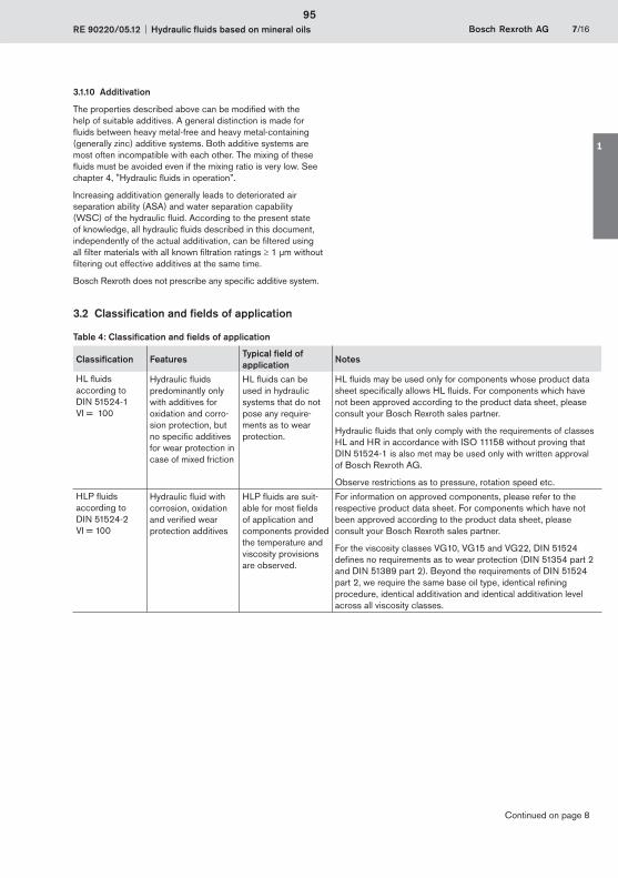
RE 90220/05.12 Hydraulic fluids based on mineral oils Bosch Rexroth AG 7/16
3.1.10 Additivation
The properties described above can be modified with the help of suitable additives. A general distinction is made for fluids between heavy metal-free and heavy metal-containing (generally zinc) additive systems. Both additive systems are most often incompatible with each other. The mixing of these fluids must be avoided even if the mixing ratio is very low. See chapter 4, "Hydraulic fluids in operation”.
Increasing additivation generally leads to deteriorated air separation ability (ASA) and water separation capability (WSC) of the hydraulic fluid. According to the present state of knowledge, all hydraulic fluids described in this document, independently of the actual additivation, can be filtered using all filter materials with all known filtration ratings 1 μm without filtering out effective additives at the same time.
Bosch Rexroth does not prescribe any specific additive system.
3.2 Classification and fields of application
Table 4: Classification and fields of application
Classification FeaturesTypical field of application
Notes
HL fluids according to DIN 51524-1 VI = 100
Hydraulic fluids predominantly only with additives for oxidation and corro-sion protection, but no specific additives for wear protection in case of mixed friction
HL fluids can be used in hydraulic systems that do not pose any require-ments as to wear protection.
HL fluids may be used only for components whose product data sheet specifically allows HL fluids. For components which have not been approved according to the product data sheet, please consult your Bosch Rexroth sales partner.
Hydraulic fluids that only comply with the requirements of classes HL and HR in accordance with ISO 11158 without proving that DIN 51524-1 is also met may be used only with written approval of Bosch Rexroth AG.
Observe restrictions as to pressure, rotation speed etc.
HLP fluids according to DIN 51524-2 VI = 100
Hydraulic fluid with corrosion, oxidation and verified wear protection additives
HLP fluids are suit-able for most fields of application and components provided the temperature and viscosity provisions are observed.
For information on approved components, please refer to the respective product data sheet. For components which have not been approved according to the product data sheet, please consult your Bosch Rexroth sales partner.
For the viscosity classes VG10, VG15 and VG22, DIN 51524 defines no requirements as to wear protection (DIN 51354 part 2 and DIN 51389 part 2). Beyond the requirements of DIN 51524 part 2, we require the same base oil type, identical refining procedure, identical additivation and identical additivation level across all viscosity classes.
Continued on page 8
95
1
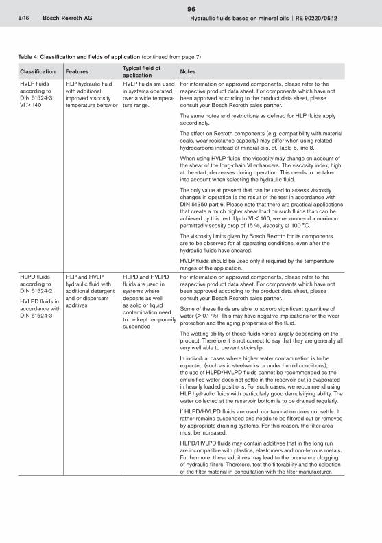
8/16 Bosch Rexroth AG Hydraulic fluids based on mineral oils RE 90220/05.12
Classification FeaturesTypical field of application
Notes
HVLP fluids according to DIN 51524-3 VI > 140
HLP hydraulic fluid with additional improved viscosity temperature behavior
HVLP fluids are used in systems operated over a wide tempera-ture range.
For information on approved components, please refer to the respective product data sheet. For components which have not been approved according to the product data sheet, please consult your Bosch Rexroth sales partner.
The same notes and restrictions as defined for HLP fluids apply accordingly.
The effect on Rexroth components (e.g. compatibility with material seals, wear resistance capacity) may differ when using related hydrocarbons instead of mineral oils, cf. Table 6, line 8.
When using HVLP fluids, the viscosity may change on account of the shear of the long-chain VI enhancers. The viscosity index, high at the start, decreases during operation. This needs to be taken into account when selecting the hydraulic fluid.
The only value at present that can be used to assess viscosity changes in operation is the result of the test in accordance with DIN 51350 part 6. Please note that there are practical applications that create a much higher shear load on such fluids than can be achieved by this test. Up to VI < 160, we recommend a maximum permitted viscosity drop of 15 %, viscosity at 100 °C.
The viscosity limits given by Bosch Rexroth for its components are to be observed for all operating conditions, even after the hydraulic fluids have sheared.
HVLP fluids should be used only if required by the temperature ranges of the application.
HLPD fluids according to DIN 51524-2,
HVLPD fluids in accordance with DIN 51524-3
HLP and HVLP hydraulic fluid with additional detergent and or dispersant additives
HLPD and HVLPD fluids are used in systems where deposits as well as solid or liquid contamination need to be kept temporarily suspended
For information on approved components, please refer to the respective product data sheet. For components which have not been approved according to the product data sheet, please consult your Bosch Rexroth sales partner.
Some of these fluids are able to absorb significant quantities of water (> 0.1 %). This may have negative implications for the wear protection and the aging properties of the fluid.
The wetting ability of these fluids varies largely depending on the product. Therefore it is not correct to say that they are generally all very well able to prevent stick-slip.
In individual cases where higher water contamination is to be expected (such as in steelworks or under humid conditions), the use of HLPD/HVLPD fluids cannot be recommended as the emulsified water does not settle in the reservoir but is evaporated in heavily loaded positions. For such cases, we recommend using HLP hydraulic fluids with particularly good demulsifying ability. The water collected at the reservoir bottom is to be drained regularly.
If HLPD/HVLPD fluids are used, contamination does not settle. It rather remains suspended and needs to be filtered out or removed by appropriate draining systems. For this reason, the filter area must be increased.
HLPD/HVLPD fluids may contain additives that in the long run are incompatible with plastics, elastomers and non-ferrous metals. Furthermore, these additives may lead to the premature clogging of hydraulic filters. Therefore, test the filterability and the selection of the filter material in consultation with the filter manufacturer.
Table 4: Classification and fields of application (continued from page 7)
96
RE 90220/05.12 Hydraulic fluids based on mineral oils Bosch Rexroth AG 9/16
4.1 GeneralThe properties of hydraulic fluids can change continually during storage and operation.
Please note that the fluid standard DIN 51524 merely describes minimum requirements for hydraulic fluids in new condition at the time of filling into the bins. The operator of a hydraulic system must ensure that the hydraulic fluid remains in a utilizable condition throughout its entire period of use.
Deviations from the characteristic values are to be clarified with the lubricant manufacturer, the test labs or Bosch Rexroth.
Please note the following aspects in operation.
4.2 Storage and handlingHydraulic fluids must be stored correctly in accordance with the instructions of the lubricant manufacturer. Avoid exposing the containers to lengthy periods of direct heat. Containers are to be stored in such a way that the risk of any foreign liquid or solid matter (e.g. water, foreign fluids or dust) ingression into the inside of the container can be ruled out. After taking hydraulic fluids from the containers, these are immediately to be properly resealed.
Recommendation:
Store containers in a dry, roofed place –
Store barrels on their sides –
Clean reservoir systems and machine reservoirs regularly –
4.3 Filling of new systemsUsually, the cleanliness levels of the hydraulic fluids as delivered do not meet the requirements of our components. Hydraulic fluids must be filtered using an appropriate filter system to minimize solid particle contamination and water in the system.
As early as possible during test operation, new systems should be filled with the selected hydraulic fluid so as to reduce the risk of accidentally mixing the fluids (see chapter 4.5 "Mixing and compatibility of different hydraulic fluids"). Changing the hydraulic medium at a later point represents significant additional costs (see following chapter).
4.4 Hydraulic fluid changeoverChangeovers, in particular between hydraulic fluids with heavy metal-free and heavy metal-containing (generally zinc) additives, frequently lead to malfunctions, see chapter 3.1.10 "Additivation".
In the case of changeovers of the fluid in hydraulic systems, it is important to ensure compatibility of the new hydraulic fluid with the remainder of the previous hydraulic fluid. We recom-mend obtaining a written performance guarantee from the manufacturer or supplier of the new hydraulic fluid. The quantity of old fluid remaining should be minimized. Mixing hydraulic fluids should be avoided, see following chapter.
For information on changing over hydraulic fluids with different classifications please refer to VDMA 24314, VDMA 24569 and ISO 15380 appendix A.
Bosch Rexroth will not accept liability for any damage to its components resulting from inadequate hydraulic fluid change-overs!
4.5 Mixing and compatibility of different hydraulic fluidsIf hydraulic fluids from different manufacturers or different types from the same manufacturer are mixed, gelling, silting and deposits may occur. These, in turn, may cause foaming, impaired air separation ability, malfunctions and damage to the hydraulic system.
If the fluid contains more than 2 % of another fluid then it is considered to be a mixture. Exceptions apply for water, see chapter 4.10 "Water".
Mixing with other hydraulic fluids is not generally permitted. This also includes hydraulic fluids with the same classification and from the market overview RE 90220-01. If individual lubri-cant manufacturers advertise miscibility and/or compatibility, this is entirely the responsibility of the lubricant manufacturer.
Bosch Rexroth customarily tests all components with mineral oil HLP before they are delivered.
Note: With connectible accessory units and mobile filtering systems, there is a considerable risk of non-permitted mixing of the hydraulic fluids!
Rexroth will not accept liability for any damage to its compo-nents resulting from mixing hydraulic fluids!
4.6 Re-additivationAdditives added at a later point in time such as colors, wear reducers, VI enhancers or anti-foam additives, may negatively affect the performance properties of the hydraulic fluid and the compatibility with our components and therefore are not permissible.
Rexroth will not accept liability for any damage to its compo-nents resulting from re-additivation!
4.7 Foaming behaviorFoam is created by rising air bubbles at the surface of hydraulic fluids in the reservoir. Foam that develops should collapse as quickly as possible.
Common hydraulic fluids in accordance with DIN 51524 are sufficiently inhibited against foam formation in new condi-tion. On account of aging and adsorption onto surfaces, the defoamer concentration may decrease over time, leading to a stable foam.
Defoamers may be re-dosed only after consultation with the lubricant manufacturer and with his written approval.
Defoamers may affect the air separation ability.
4 Hydraulic fluids in operation
97
1

10/16 Bosch Rexroth AG Hydraulic fluids based on mineral oils RE 90220/05.12
4.8 CorrosionThe hydraulic fluid is to guarantee sufficient corrosion protec-tion of components under all operating conditions, even in the event of impermissible water contamination.
During storage and operation, hydraulic fluid based on mineral oils with anti-corrosion additives protect components against water and "acidic" oil degradation products.
4.9 AirUnder atmospheric conditions, the hydraulic fluid contains dissolved air. In the negative pressure range, for instance in the suction pipe of the pump or downstream of control edges, this dissolved air may transform into undissolved air. The undissolved air content represents a risk of cavitation and of the diesel effect. This results in material erosion of components and increased hydraulic fluid aging.
With the correct measures, such as suction pipe and reservoir design, and an appropriate hydraulic fluid, air intake and separation can be positively influenced.
See also chapter 3.1.7 "Air separation ability (ASA)”.
4.10 WaterWater contamination in hydraulic fluids can result from direct ingress or indirectly through condensation of water from the air due to temperature variations.
Water in the hydraulic fluid may result in wear or direct failure of hydraulic components. Furthermore, a high water content in the hydraulic fluid negatively affects aging and filterability and increases susceptibility to cavitation.
Undissolved water can be drained from the bottom of the reservoir. Dissolved water can be removed only by using appropriate measures. If the hydraulic system is used in humid conditions, preventive measures need to be taken, such as an air dehumidifier at the reservoir vent. During operation, the water content in all hydraulic fluids, determined according to the "Karl Fischer method" (see chapter 6 "Glossary") for all hy-draulic fluids must constantly be kept below 0.1% (1000 ppm). To ensure a long service life of both hydraulic fluids and components, Bosch Rexroth recommends that values below 0.05% (500 ppm) are permanently maintained.
To ensure a long service life for the hydraulic fluids and the components, we recommend that values below 0.05 % (500 ppm) are permanently maintained. Detergent and or dispersant hydraulic fluids (HLPD / HVLPD) are able to absorb (and keep suspended) more water. Prior to using these hydraulic fluids, please contact the lubricant manufacturer.
4.11 Fluid servicing, fluid analysis and filtrationAir, water, operating temperature influences and solid matter contamination will change the performance characteristics of hydraulic fluids and cause them to age.
To preserve the usage properties and ensure a long service life for hydraulic fluid and components, the monitoring of the fluid condition and a filtration adapted to the application require-ments (draining and degassing if required) are indispensable.
The effort is higher in the case of unfavorable usage conditions, increased stress for the hydraulic system or high expectations as to availability and service life, see chapter 2 "Solid particle contamination and cleanliness level".
When commissioning a system, please note that the required minimum cleanliness level can frequently be attained only by flushing the system. Due to severe start-up contamination, it may be possible that a fluid and/or filter replacement becomes necessary after a short operating period (< 50 operating hours).
The hydraulic fluid must be replaced in regular intervals and tested by the lubricant manufacturer or recognized, accredited test labs. We recommend a reference analysis after com-missioning.
The minimum data to be tested for analyses are:
Viscosity at 40 °C and 100 °C –
Neutralization number NN (acid number AN) –
Water content (Karl-Fischer method) –
Particle measurement with evaluation according to ISO 4406 –or mass of solid foreign substances with evaluation to EN 12662
Element analysis (RFA (EDX) / ICP, specify test method) –
Comparison with new product or available trend analyses –
Assessment / evaluation for further use –
Also recommended: IR spectrum –
Compared to the pure unused hydraulic fluid, the changed neutralization number NN (acid number AN) indicates how many aging products are contained in the hydraulic fluid. This value must be kept as low as possible. As soon as the trend analysis notes a significant increase in the acid number, the lubricant manufacturer should be contacted.
In case of warranty, liability or guarantee claims to Bosch Rexroth, service verification and/or the results of fluid analyses are to be provided.
98

RE 90220/05.12 Hydraulic fluids based on mineral oils Bosch Rexroth AG 11/16
5 Disposal and environmental protection
Hydraulic fluids based on mineral oil and related hydrocarbons are hazardous for the environment. They are subject to a special disposal obligation.
The respective lubricant manufacturers provide specifications on environmentally acceptable handling and storage. Please ensure that spilt or splashed fluids are absorbed with appropri-ate adsorbents or by a technique that prevents it contaminating water courses, the ground or sewerage systems.
It is also not permitted to mix fluids when disposing of hydraulic fluids. Regulations governing the handing of used oils stipulate that used oils are not to mixed with other products, e.g. substances containing halogen. Non-compliance will increase disposal costs. Comply with the national legal provisions concerning the disposal of the corresponding hydraulic fluid. Comply with the local safety data sheet of the lubricant manufacturer for the country concerned.
99
1
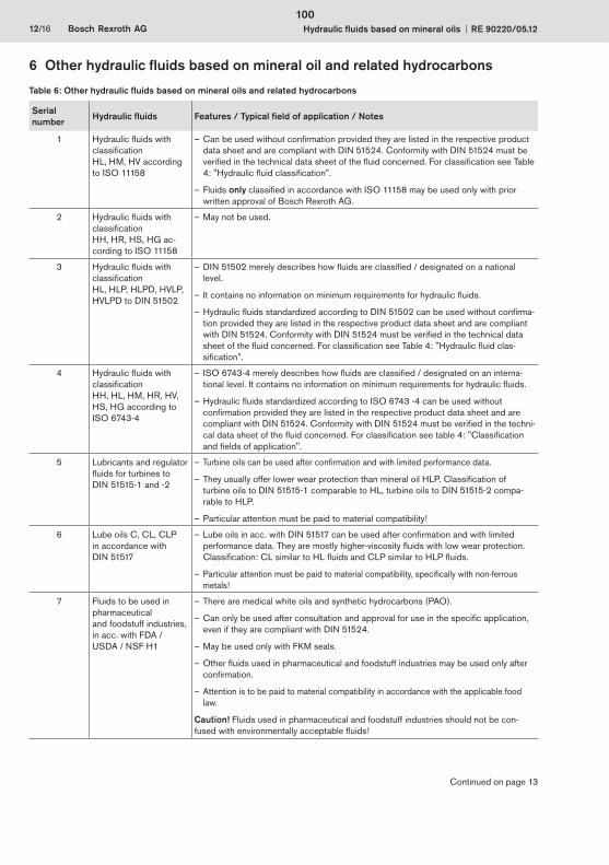
12/16 Bosch Rexroth AG Hydraulic fluids based on mineral oils RE 90220/05.12
6 Other hydraulic fluids based on mineral oil and related hydrocarbons
Table 6: Other hydraulic fluids based on mineral oils and related hydrocarbons
Serial number
Hydraulic fluids Features / Typical field of application / Notes
1 Hydraulic fluids with classification HL, HM, HV according to ISO 11158
Can be used without confirmation provided – they are listed in the respective product data sheet and are compliant with DIN 51524. Conformity with DIN 51524 must be verified in the technical data sheet of the fluid concerned. For classification see Table 4: "Hydraulic fluid classification”.
Fluids – only classified in accordance with ISO 11158 may be used only with prior written approval of Bosch Rexroth AG.
2 Hydraulic fluids with classification HH, HR, HS, HG ac-cording to ISO 11158
May not be used. –
3 Hydraulic fluids with classification HL, HLP, HLPD, HVLP, HVLPD to DIN 51502
DIN 51502 merely describes how fluids are classified / designated on a national –level.
It contains no information on minimum requirements for hydraulic fluids. –
Hydraulic fluids standardized according to DIN 51502 can be used without confirma- –tion provided they are listed in the respective product data sheet and are compliant with DIN 51524. Conformity with DIN 51524 must be verified in the technical data sheet of the fluid concerned. For classification see Table 4: "Hydraulic fluid clas-sification”.
4 Hydraulic fluids with classification HH, HL, HM, HR, HV, HS, HG according to ISO 6743-4
ISO 6743-4 merely describes how fluids are classified / designated on an interna- –tional level. It contains no information on minimum requirements for hydraulic fluids.
Hydraulic fluids standardized according to ISO 6743 -4 can be used without –confirmation provided they are listed in the respective product data sheet and are compliant with DIN 51524. Conformity with DIN 51524 must be verified in the techni-cal data sheet of the fluid concerned. For classification see table 4: "Classification and fields of application".
5 Lubricants and regulator fluids for turbines to DIN 51515-1 and -2
Turbine oils can be used after confirmation and with limited performance data. –
They – usually offer lower wear protection than mineral oil HLP. Classification of turbine oils to DIN 51515-1 comparable to HL, turbine oils to DIN 51515-2 compa-rable to HLP.
Particular attention must be paid to material compatibility! –
6 Lube oils C, CL, CLP in accordance with DIN 51517
Lube oils in acc. with DIN 51517 can be used after confirmation and with limited –performance data. They are mostly higher-viscosity fluids with low wear protection. Classification: CL similar to HL fluids and CLP similar to HLP fluids.
Particular attention must be paid to material compatibility, specifically with non-ferrous –metals!
7 Fluids to be used in pharmaceutical and foodstuff industries, in acc. with FDA / USDA / NSF H1
There are medical white oils and synthetic hydrocarbons (PAO). –
Can only be used after consultation and approval for use in the specific application, –even if they are compliant with DIN 51524.
May be used only with FKM seals. –
Other fluids used in pharmaceutical and foodstuff industries may be used only after –confirmation.
Attention is to be paid to material compatibility in accordance with the applicable food –law.
Caution! Fluids used in pharmaceutical and foodstuff industries should not be con-fused with environmentally acceptable fluids!
Continued on page 13
100
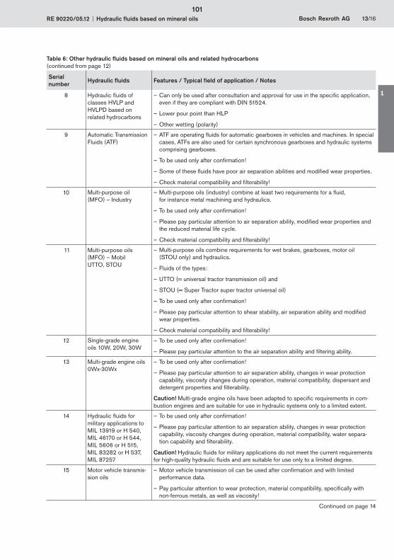
RE 90220/05.12 Hydraulic fluids based on mineral oils Bosch Rexroth AG 13/16
Table 6: Other hydraulic fluids based on mineral oils and related hydrocarbons (continued from page 12)
Serial number
Hydraulic fluids Features / Typical field of application / Notes
8 Hydraulic fluids of classes HVLP and HVLPD based on related hydrocarbons
Can only be used after consultation and approval for use in the specific application, –even if they are compliant with DIN 51524.
Lower pour point than HLP –
Other wetting (polarity) –
9 Automatic Transmission Fluids (ATF)
ATF are operating fluids for automatic gearboxes in vehicles and machines. In special –cases, ATFs are also used for certain synchronous gearboxes and hydraulic systems comprising gearboxes.
To be used only after confirmation! –
Some of these fluids have poor air separation abilities and modified wear properties. –
Check material compatibility and filterability! –
10 Multi-purpose oil (MFO) – Industry
Multi-purpose oils (industry) combine at least two requirements for a fluid, –for instance metal machining and hydraulics.
To be used only after confirmation! –
Please pay particular attention to air separation ability, modified wear properties and –the reduced material life cycle.
Check material compatibility and filterability! –
11 Multi-purpose oils (MFO) – Mobil UTTO, STOU
Multi-purpose oils combine requirements for wet brakes, gearboxes – , motor oil (STOU only) and hydraulics.
Fluids of the types: –
UTTO (= universal tractor transmission oil) and –
STOU (= Super Tractor – super tractor universal oil)
To be used only after confirmation! –
Please pay particular attention to shear stability, air separation ability and modified –wear properties.
Check material compatibility and filterability! –
12 Single-grade engine oils 10W, 20W, 30W
To be used only after confirmation! –
Please pay particular attention to the air separation ability and filtering ability. –
13 Multi-grade engine oils 0Wx-30Wx
To be used only after confirmation! –
Please pay particular attention to air separation ability, changes in wear protection –capability, viscosity changes during operation, material compatibility, dispersant and detergent properties and filterability.
Caution! Multi-grade engine oils have been adapted to specific requirements in com-bustion engines and are suitable for use in hydraulic systems only to a limited extent.
14 Hydraulic fluids for military applications to MIL 13919 or H 540, MIL 46170 or H 544, MIL 5606 or H 515, MIL 83282 or H 537, MIL 87257
To be used only after confirmation! –
Please pay particular attention to air separation ability, changes in wear protection –capability, viscosity changes during operation, material compatibility, water separa-tion capability and filterability.
Caution! Hydraulic fluids for military applications do not meet the current requirements for high-quality hydraulic fluids and are suitable for use only to a limited degree.
15 Motor vehicle transmis-sion oils
Motor vehicle transmission oil can be used after confirmation and with limited –performance data.
Pay particular attention to wear protection, material compatibility, specifically with –non-ferrous metals, as well as viscosity!
Continued on page 14
101
1
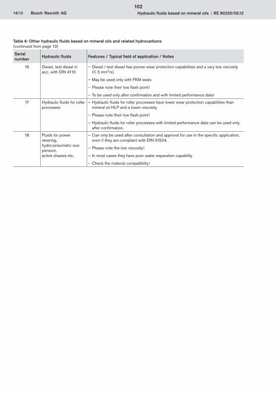
14/16 Bosch Rexroth AG Hydraulic fluids based on mineral oils RE 90220/05.12
Serial number
Hydraulic fluids Features / Typical field of application / Notes
16 Diesel, test diesel in acc. with DIN 4113
Diesel / test diesel has poorer wear protection capabilities and a very low viscosity –(< 3 mm2/s).
May be used only with FKM seals –
Please note their low flash point! –
To be used only after confirmation and with limited performance data! –
17 Hydraulic fluids for roller processes
Hydraulic fluids for roller processes – have lower wear protection capabilities than mineral oil HLP and a lower viscosity
Please note their low flash point! –
Hydraulic fluids for roller processes – with limited performance data can be used only after confirmation.
18 Fluids for power steering, hydro-pneumatic sus-pension, active chassis etc.
Can only be used after consultation and approval for use in the specific application, –even if they are compliant with DIN 51524.
Please note the low viscosity! –
In most cases they have poor water separation capability –
Check the material compatibility! –
Table 6: Other hydraulic fluids based on mineral oils and related hydrocarbons (continued from page 13)
102
RE 90220/05.12 Hydraulic fluids based on mineral oils Bosch Rexroth AG 15/16
AdditivationAdditives are chemical substances added to the basic fluids to achieve or improve specific properties.
AgingHydraulic fluids age due to oxidation (see chapter 3.1.5 "Aging resistance"). Liquid and solid contamination acts as a catalyzer for aging, meaning that it needs to be minimized as far as possible by careful filtration.
API classificationClassification of basic fluids by the American Petroleum Institute (API) – the largest association representing the US oil and gas industry.
Arrhenius equationThe quantitative relation between reaction rate and temperature is described by an exponential function, the Arrhenius equation. This function is usually visualized within the typical temperature range of the hydraulic system. For a practical example, see chapter 3.1.5 "Aging resistance”.
Related hydrocarbonsRelated hydrocarbons are hydrocarbon compounds that are not classified as API class 1, 2 or 5.
Basic fluidsIn general, a hydraulic fluid is made up of a basic fluid, or base oil, and chemical substances, the so-called additives. The proportion of basic fluid is generally greater than 90%.
DemulsifyingAbility of a fluid to separate water contamination quickly; achieved with careful selection of base oil and additives.
Detergent Ability of certain additives to emulsify part of the water contami-nation in the oil or to hold it in suspension until it has evapo-rated with increasing temperature. Larger water quantities, in contrast (above approx. 2 %), are separated immediately.
DispersantAbility of certain additives to keep insoluble liquid and solid contamination in suspension in the fluid.
Diesel effectIf hydraulic fluid that contains air bubbles is compressed quickly, the bubbles are heated to such a degree that a self-ignition of the air-gas mix may occur. The resultant temperature increase may lead to seal damage and increased aging of the hydraulic fluid.
Hydraulic fluids based on mineral oilsHydraulic fluids based on mineral oils are made from petroleum (crude oil).
ICP (atomic emission spectroscopy)The ICP procedure can be used to determine various wear metals, contamination types and additives. Practically all elements in the periodic system can be detected with this method.
Karl Fischer methodMethod to determine the water content in fluids. Indirect coulometric determination procedure in accordance with DIN EN ISO 12937 in connection with DIN 51777-2. Only the combination of both standards will assure adequately accurate measured values.
CavitationCavitation is the creation of cavities in fluids due to pressure reduction below the saturated vapour pressure and subse-quent implosion when the pressure increases. When the cavities implode, extremely high acceleration, temperatures and pressure may occur temporarily, which may damage the component surfaces.
Neutralization number (NN)The neutralization number (NN) or acid number (AN) specifies the amount of caustic potash required to neutralize the acid contained in one gram of fluid.
Pour point The lowest temperature at which the fluid still just flows when cooled down under set conditions. The pour point is specified in the lubricant manufacturers' technical data sheets as a reference value for achieving this flow limit.
RFA (wavelength dispersive x-ray fluorescence analysis)Is a procedure to determine nearly all elements in liquid and solid samples with nearly any composition. This analysis method is suitable for examining additives and contamination, delivering fast results.
Shearing/shear lossShearing of molecule chains during operation can change the viscosity of hydraulic fluids with long chain VI enhancers. The initially high viscosity index drops. This needs to be taken into account when selecting the hydraulic fluid.
The only value at present that can be used to assess viscosity changes in operation is the result of the test in accordance with DIN 51350 part -6. Please note that there are practical applications that create a much higher shear load on such hydraulic fluids than can be achieved by this test.
Stick-slip effect (sliding) Interaction between a resilient mass system involving friction (such as cylinder + oil column + load) and the pressure increase at very low sliding speeds. The static friction of the system is a decisive value here. The lower it is, the lower the speed that can still be maintained without sticking. Depend-ing on the tribologic system, the stick-slip effect may lead to vibrations generated and sometimes also to significant noise emission. In many cases, the effect can be attenuated by replacing the lubricant.
ViscosityViscosity is the measure of the internal friction of a fluid to flow. It is defined as the property of a substance to flow under tension. Viscosity is the most important characteristic for describing the load-bearing capacity of a hydraulic fluid.
Kinematic viscosity is the ratio of the dynamic viscosity and the density of the fluid; the unit is mm²/s. Hydraulic fluids are clas-sified by their kinematic viscosity into ISO viscosity classes. The reference temperature for this is 40 °C.
Viscosity index (VI)Refers to the viscosity temperature behavior of a fluid. The lower the change of viscosity in relation the temperature, the higher the VI.
7 Glossary
103
1

16/16 Bosch Rexroth AG Hydraulic fluids based on mineral oils RE 90220/05.12
Bosch Rexroth AGHydraulicsZum Eisengießer 197816 Lohr am Main, GermanyPhone +49 (0) 93 52 / 18-0Fax +49 (0) 93 52 / 18-23 [email protected]
© This document, as well as the data, specifications and other information set forth in it, are the exclusive property of Bosch Rexroth AG. It may not be reproduced or given to third parties without its consent.
No statements concerning the suitability of a hydraulic fluid for a specific purpose can be derived from our information. The information given does not release the user from the obligation of own judgment and verification.
It must be remembered that our products are subject to a natural process of wear and aging.
Subject to change.
104
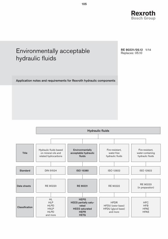
Application notes and requirements for Rexroth hydraulic components
Environmentally acceptable hydraulic fluids
RE 90221/05.12 1/14Replaces: 05.10
Hydraulic fluids
TitleHydraulic fluids based
on mineral oils and related hydrocarbons
Environmentally acceptable hydraulic
fluids
Fire-resistant, water-free
hydraulic fluids
Fire-resistant, water-containing hydraulic fluids
Standard DIN 51524 ISO 15380 ISO 12922 ISO 12922
Data sheets RE 90220 RE 90221 RE 90222 RE 90223
(in preparation)
Classification
HLHLP
HLPDHVLPHLPD
and more
HEPGHEES partially satu-
ratedHEES saturated
HEPRHETG
HFDRHFDU (ester base)HFDU (glycol base)
and more
HFCHFBHFAEHFAS
105
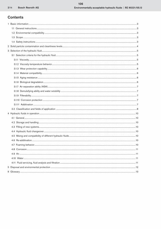
2/14 Bosch Rexroth AG Environmentally acceptable hydraulic fluids RE 90221/05.12
Contents
1 Basic information .................................................................................................................................................................................................3
1.1 General instructions ...................................................................................................................................................................................3
1.2 Environmental compatibility .....................................................................................................................................................................3
1.3 Scope ...........................................................................................................................................................................................................3
1.4 Safety instructions .....................................................................................................................................................................................3
2 Solid particle contamination and cleanliness levels .....................................................................................................................................4
3 Selection of the hydraulic fluid ..........................................................................................................................................................................5
3.1 Selection criteria for the hydraulic fluid .................................................................................................................................................5
3.1.1 Viscosity .................................................................................................................................................................................................5
3.1.2 Viscosity-temperature behavior ........................................................................................................................................................5
3.1.3 Wear protection capability ................................................................................................................................................................6
3.1.4 Material compatibility..........................................................................................................................................................................6
3.1.5 Aging resistance .................................................................................................................................................................................6
3.1.6 Biological degradation .......................................................................................................................................................................6
3.1.7 Air separation ability (ASA) ...............................................................................................................................................................7
3.1.8 Demulsifying ability and water solubility ........................................................................................................................................7
3.1.9 Filterability .............................................................................................................................................................................................7
3.1.10 Corrosion protection ........................................................................................................................................................................7
3.1.11 Additivation .........................................................................................................................................................................................7
3.2 Classification and fields of application ................................................................................................................................................8
4 Hydraulic fluids in operation ............................................................................................................................................................................10
4.1 General .......................................................................................................................................................................................................10
4.2 Storage and handling .............................................................................................................................................................................10
4.3 Filling of new systems.............................................................................................................................................................................10
4.4 Hydraulic fluid changeover ....................................................................................................................................................................10
4.5 Mixing and compatibility of different hydraulic fluids .......................................................................................................................10
4.6 Re-additivation ..........................................................................................................................................................................................10
4.7 Foaming behavior .....................................................................................................................................................................................10
4.8 Corrosion ...................................................................................................................................................................................................11
4.9 Air ................................................................................................................................................................................................................11
4.10 Water ........................................................................................................................................................................................................11
4.11 Fluid servicing, fluid analysis and filtration .......................................................................................................................................11
5 Disposal and environmental protection ........................................................................................................................................................12
6 Glossary ...............................................................................................................................................................................................................13
106
RE 90221/05.12 Environmentally acceptable hydraulic fluids Bosch Rexroth AG 3/14
1 Basic information
1.1 General instructionsThe hydraulic fluid is the common element in any hydraulic component and must be selected very carefully. Quality and cleanliness of the hydraulic fluid are decisive factors for the operational reliability, efficiency and service life of a system.
Hydraulic fluids must conform, be selected and used in accordance with the generally acknowledged rules of technol-ogy and safety provisions. Reference is made to the country-specific standards and directives (in Germany the directive of the Employer's Liability Insurance Association BGR 137).
This data sheet includes recommendations and regulations concerning the selection, operation and disposal of envi-ronmentally compatible hydraulic fluids in the application of Rexroth hydraulic components.
The individual selection of hydraulic fluid or the choice of classification are the responsibility of the operator.
It is the responsibility of the user to ensure that appropriate measures are taken for safety and health protection and to ensure compliance with statutory regulations. The recommendations of the lubricant manufacturer and the specifications given in the safety data sheet are to be observed when using hydraulic fluid.
This data sheet does not absolve the operator from verifying the conformity and suitability of the respective hydraulic fluid for his system. He is to ensure that the selected fluid meets the minimum requirements of the relevant fluid standard during the whole of the period of use.
Other regulations and legal provisions may also apply. The operator is responsible for their observance, e.g. EU directive 2004/35/EG, 2005/360/EG and their national implementation. In Germany the Water Resources Act (WHG) is also to be observed.
We recommend that you maintain constant, close contact with lubricant manufacturers to support you in the selection, maintenance, care and analyses.
When disposing of used hydraulic fluids, apply the same care as during use.
Environmentally acceptable hydraulic fluids have been used successfully for many years. In some countries, the use of envi-ronmentally acceptable hydraulic fluids is already prescribed in ecologically sensitive areas (e.g. forestry, locks, weirs).
Environmentally acceptable hydraulic fluids may only be used in the pharmaceutical and food industry subject to required certification to FDA/USDA/NSF H1.
1.2 Environmental compatibilityThere is no unambiguous legal definition for environmentally acceptable hydraulic fluids as different testing procedures can be applied for biological degradation and toxicity.
According to ISO 15380 the definition of "environmentally acceptable" is as follows: Humans, animals, plants, air and soil must not be endangered. With regard to hydraulic fluids in an unused condition in the bin this mainly means:
biological degradation – at least 60 % (according to ISO 14593 or ISO 9439)
acute fish toxicity – at least 100 mg/l (according to ISO 7346-2)
acute daphnia toxicity – at least 100 mg/l (according to ISO 5341)
acute bacteria toxicity – at least 100 mg/l (according to ISO 8192)
The same amount of care should be taken when handling environmentally acceptable hydraulic fluids as for mineral oils, leakage from the hydraulic system should be avoided. Environ-mentally acceptable hydraulic fluids are designed so that in the event of accidents and leakage,less permanent environmental damage is caused than by mineral oils, see also chapter 5 "Disposal and environmental protection".
In comparison to mineral oil HLP/HVLP , the biological deg-radation of environmentally acceptable hydraulic fluids may change fluid aging, see chapter 3.1.5 "Aging resistance", 3.1.6. "Biological degradation" and 4 "Hydraulic fluids in operation".
1.3 ScopeThis data sheet must be applied when using environmentally acceptable hydraulic fluids with Rexroth hydraulic components. The specifications of this data sheet may be further restricted by the specification given in the data sheets for the individual components.
The use of the individual environmentally acceptable hydraulic fluids in accordance with the intended purpose can be found in the safety data sheets or other product description documents of the lubricant manufacturers. In addition, each use is to be individually considered.
Rexroth hydraulic components may only be operated with environmentally acceptable hydraulic fluids according to ISO 15380 if specified in the respective component data sheet or if a Rexroth approval for use is furnished.
The manufacturers of hydraulic systems must adjust their systems and operating instructions to the environmentally acceptable hydraulic fluids.
Notes: In the market overview RE 90221-01, environmentally accept-able hydraulic fluids based on mineral oil are described which, according to the information of the lubricant manufacturer, feature the respective parameters of the current requirements standard ISO 15380 and other parameters which are of rel-evance for suitability in connection with Rexroth components.
These specifications are not checked or monitored by Bosch Rexroth. The list in the market overview does not therefore represent a recommendation on the part of Rexroth or approval of the respective hydraulic fluid for use with Rexroth compo-nents and does not release the operator from his responsibility regarding selection of the hydraulic fluid.
Bosch Rexroth will accept no liability for its components for any damage resulting from failure to comply with the notes below.
1.4 Safety instructionsHydraulic fluids can constitute a risk for persons and the environment. These risks are described in the hydraulic fluid safety data sheets. The operator is to ensure that a current safety data sheet for the hydraulic fluid used is available and that the measures stipulated therein are complied with.
107
1
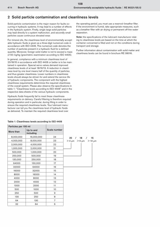
4/14 Bosch Rexroth AG Environmentally acceptable hydraulic fluids RE 90221/05.12
Solid particle contamination is the major reason for faults oc-curring in hydraulic systems. It may lead to a number of effects in the hydraulic system. Firstly, single large solid particles may lead directly to a system malfunction, and secondly small particles cause continuous elevated wear.
For mineral oils, the cleanliness level of environmentally accept-able hydraulic fluids is given as a three-digit numerical code in accordance with ISO 4406. This numerical code denotes the number of particles present in a hydraulic fluid for a defined quantity. Moreover, foreign solid matter is not to exceed a mass of 50 mg/kg (gravimetric examination according to ISO 4405).
In general, compliance with a minimum cleanliness level of 20/18/15 in accordance with ISO 4406 or better is to be main-tained in operation. Special servo valves demand improved cleanliness levels of at least 18/16/13. A reduction in cleanli-ness level by one level means half of the quantity of particles and thus greater cleanliness. Lower numbers in cleanliness levels should always be striven for and extend the service life of hydraulic components. The component with the highest cleanliness requirements determines the required cleanliness of the overall system. Please also observe the specifications in table 1: "Cleanliness levels according to ISO 4406" and in the respective data sheets of the various hydraulic components.
Hydraulic fluids frequently fail to meet these cleanliness requirements on delivery. Careful filtering is therefore required during operation and in particular, during filling in order to ensure the required cleanliness levels. Your lubricant manu-facturer can tell you the cleanliness level of hydraulic fluids as delivered. To maintain the required cleanliness level over
Table 1: Cleanliness levels according to ISO 4406
Particles per 100 ml Scale number
More than Up to and including
8,000,000 16,000,000 24
4,000,000 8,000,000 23
2,000,000 4,000,000 22
1,000,000 2,000,000 21
500,000 1,000,000 20
250,000 500,000 19
130,000 250,000 18
64000 130,000 17
32000 64000 16
16000 32000 15
8000 16000 14
4000 8000 13
2000 4000 12
1000 2000 11
500 1000 10
250 500 9
130 250 8
64 130 7
32 64 6
20 / 18 / 15 > 4 μm > 6 μm > 14 μm
2 Solid particle contamination and cleanliness levels
the operating period, you must use a reservoir breather filter. If the environment is humid, take appropriate measures, such as a breather filter with air drying or permanent off-line water separation.
Note: the specifications of the lubricant manufacturer relat-ing to cleanliness levels are based on the time at which the container concerned is filled and not on the conditions during transport and storage.
Further information about contamination with solid matter and cleanliness levels can be found in brochure RE 08016.
108
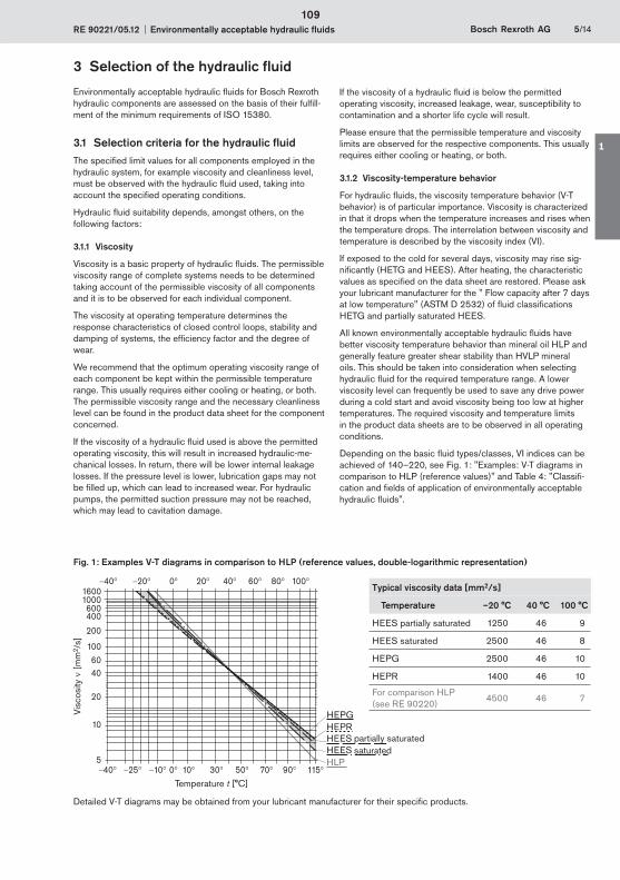
RE 90221/05.12 Environmentally acceptable hydraulic fluids Bosch Rexroth AG 5/14
3 Selection of the hydraulic fluid
Environmentally acceptable hydraulic fluids for Bosch Rexroth hydraulic components are assessed on the basis of their fulfill-ment of the minimum requirements of ISO 15380.
3.1 Selection criteria for the hydraulic fluidThe specified limit values for all components employed in the hydraulic system, for example viscosity and cleanliness level, must be observed with the hydraulic fluid used, taking into account the specified operating conditions.
Hydraulic fluid suitability depends, amongst others, on the following factors:
3.1.1 Viscosity
Viscosity is a basic property of hydraulic fluids. The permissible viscosity range of complete systems needs to be determined taking account of the permissible viscosity of all components and it is to be observed for each individual component.
The viscosity at operating temperature determines the response characteristics of closed control loops, stability and damping of systems, the efficiency factor and the degree of wear.
We recommend that the optimum operating viscosity range of each component be kept within the permissible temperature range. This usually requires either cooling or heating, or both. The permissible viscosity range and the necessary cleanliness level can be found in the product data sheet for the component concerned.
If the viscosity of a hydraulic fluid used is above the permitted operating viscosity, this will result in increased hydraulic-me-chanical losses. In return, there will be lower internal leakage losses. If the pressure level is lower, lubrication gaps may not be filled up, which can lead to increased wear. For hydraulic pumps, the permitted suction pressure may not be reached, which may lead to cavitation damage.
If the viscosity of a hydraulic fluid is below the permitted operating viscosity, increased leakage, wear, susceptibility to contamination and a shorter life cycle will result.
Please ensure that the permissible temperature and viscosity limits are observed for the respective components. This usually requires either cooling or heating, or both.
3.1.2 Viscosity-temperature behavior
For hydraulic fluids, the viscosity temperature behavior (V-T behavior) is of particular importance. Viscosity is characterized in that it drops when the temperature increases and rises when the temperature drops. The interrelation between viscosity and temperature is described by the viscosity index (VI).
If exposed to the cold for several days, viscosity may rise sig-nificantly (HETG and HEES). After heating, the characteristic values as specified on the data sheet are restored. Please ask your lubricant manufacturer for the " Flow capacity after 7 days at low temperature" (ASTM D 2532) of fluid classifications HETG and partially saturated HEES.
All known environmentally acceptable hydraulic fluids have better viscosity temperature behavior than mineral oil HLP and generally feature greater shear stability than HVLP mineral oils. This should be taken into consideration when selecting hydraulic fluid for the required temperature range. A lower viscosity level can frequently be used to save any drive power during a cold start and avoid viscosity being too low at higher temperatures. The required viscosity and temperature limits in the product data sheets are to be observed in all operating conditions.
Depending on the basic fluid types/classes, VI indices can be achieved of 140–220, see Fig. 1: "Examples: V-T diagrams in comparison to HLP (reference values)" and Table 4: "Classifi-cation and fields of application of environmentally acceptable hydraulic fluids".
Fig. 1: Examples V-T diagrams in comparison to HLP (reference values, double-logarithmic representation)
HLPHEESHEESHEPRHEPG
40 25 10 10 30 50 90 1157005
10
4060
20
100
200
400600
10001600
0 20 40 60 80 10040 20
Temperature t [°C]
Visc
osity
[
mm
2 /s]
partially saturatedsaturated
Detailed V-T diagrams may be obtained from your lubricant manufacturer for their specific products.
Typical viscosity data [mm2/s]
Temperature –20 °C 40 °C 100 °C
HEES partially saturated 1250 46 9
HEES saturated 2500 46 8
HEPG 2500 46 10
HEPR 1400 46 10
For comparison HLP (see RE 90220)
4500 46 7
109
1
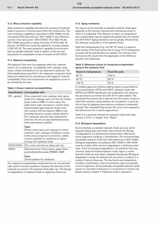
6/14 Bosch Rexroth AG Environmentally acceptable hydraulic fluids RE 90221/05.12
3.1.3 Wear protection capability
Wear protection capability describes the property of hydraulic fluids to prevent or minimize wear within the components. The wear protection capability is described in ISO 15380 via test procedures"FZG gear test rig" (ISO 14635-1) and "Mechani-cal test in the vane pump" (ISO 20763). From ISO VG 32, ISO 15380 prescribes a rating of at least 10 (FZG test). At present, the FZG test cannot be applied to viscosity classes < ISO VG 32. The wear protection capability of environmen-tally acceptable hydraulic fluids in relation to the two test procedures is comparable to that of mineral oil HLP/HVLP.
3.1.4 Material compatibility
The hydraulic fluid must not negatively affect the materials used in the components. Compatibility with coatings, seals, hoses, metals and plastics is to be observed in particular. The fluid classifications specified in the respective component data sheets are tested by the manufacturer with regard to material compatibility. Parts and components not supplied by us are to be checked by the user.
Table 2: Known material incompatibilities
Classification Incompatible with:
HE... general One-component color coatings, lead, galva-nized zinc coatings, some non-ferrous metals, seals made of NBR. In some cases, the latter show major increases in volume when impermissibly aged hydraulic fluids come into contact with the material. NBR is only permitted by prior consent, please observe the customary seal and tube replacement intervals. Do not use any hydrolysis/suscep-tible polyurethane qualities.
NotePlease check seals and coatings of control cabinets, outer coatings of hydraulic compo-nents and accessories (connectors, cables, control cabinets) for resistance to vapors issuing from hydraulic fluids.
HETG/HEES Zinc, some non-ferrous alloys with zinc
HEPG Steel/aluminum tribocontacts, paper filters, polymethylmethacrylate (PMMA), NBR
NoteCheck plastics for resistance
The material incompatibilities mentioned here do not automati-cally result in function problems. However the elements of the materials are found in the hydraulic fluids after use. The biologi-cal degradation of hydraulic fluids is negatively influenced.
3.1.5 Aging resistance
The way an environmentally acceptable hydraulic fluids ages depends on the thermal, chemical and mechanical stress to which it is subjected. The influence of water, air, temperature and contamination may be significantly greater than for mineral oils HLP/HVLP. Aging resistance can be greatly influenced by the chemical composition of the hydraulic fluids .
High fluid temperatures (e.g. over 80 °C) result in a approxi-mate halving of the fluid service life for every 10 °C temperature increase and should therefore by avoided. The halving of the fluid service life results from the application of the Arrhenius equation (see Glossary).
Table 3: Reference values for temperature-dependent aging of the hydraulic fluid
Reservoir temperature Fluid life cycle
80 °C 100 %
90 °C 50 %
100 °C 25 %
A modified aging test (without adding water) is prescribed for fluid classifications HETG and HEES. Hydraulic fluids with HEPG and HEPR classification are subjected to the identical test procedure as mineral oils (with 20 % water added). The calculated fluid service life is derived from the results of tests in which the long-term characteristics are simulated in a short pe-riod of time by applying more arduous conditions (condensed testing). This calculated fluid service life is not to be equated to the fluid service life in real-life applications.
Table 3 is a practical indicator for hydraulic fluids with water content < 0.1%, cf. chapter 4.10. "Water".
3.1.6 Biological degradation
Environmentally acceptable hydraulic fluids are ones which degrade biologically much faster than mineral oils. Biologi-cal degradation is a biochemical transformation effected by micro-organisms resulting in mineralization. For environmentally acceptable hydraulic fluids that make reference to ISO 15380, biological degradation according to ISO 14593 or ISO 9439 must be verified. 60% minimum degradation is defined as limit value. Proof of biological degradation is furnished for the new, unmixed, ready-formulated hydraulic fluids. Aged or mixed hydraulic fluids are less able to degrade biologically. Biological degradation outside the defined test procedure is subject to a variety of natural influences. The key factors are temperature, humidity, contamination, fluid concentration, type and quantity of micro-organisms. Environmentally acceptable hydraulic fluids require no extended maintenance in comparison to mineral oils, please observe chapter 4 "Hydraulic fluids in operation".
110
RE 90221/05.12 Environmentally acceptable hydraulic fluids Bosch Rexroth AG 7/14
3.1.7 Air separation ability (ASA)
The air separation ability (ASA) describes the property of a hydraulic fluid to separate undissolved air. Hydraulic fluids always contain dissolved air. During operation, dissolved air may be transformed into undissolved air, leading to cavitation damages. Fluid classification, fluid product, reservoir size and design must be coordinated to take into account the dwell time and ASA value of the hydraulic fluid. The air separation capacity depends on the viscosity, temperature, basic fluid and aging. It cannot be improved by additives.
According to ISO 15380, for instance, an ASA value 10 minutes is required for viscosity class ISO VG 46, 6 minutes are typical, lower values are preferable.
3.1.8 Demulsifying ability and water solubility
The capacity of a hydraulic fluid to separate water at a defined temperature is known as the demulsifying ability. ISO 6614 defines the demulsifying properties of hydraulic fluids.
Fluids classified HETG, HEES and HEPR separate from water. HETG and HEES hydraulic fluids have a different water separation ability to mineral oil HLP/HVLP. At 20 °C, in comparison to mineral oil HLP/HVLP, a multiple ( > factor 3) of water can separate in the hydraulic fluid. Water solubility is also more temperature-dependent than for mineral oils. With regard to water solubility, HEPR hydraulic fluids behave like HVLP hydraulic fluids (see RE 90220). In the majority of cases, HEPG-classified fluids HEPG dissolve water completely , see chapter "4.10 Water".
3.1.9 Filterability
Filterability describes the ability of a hydraulic fluid to pass through a filter, removing solid contaminants. The hydraulic fluids used require a good filterability, not just when new, but also during the whole of their service life. Depending on the different basic fluids (glycols, saturated and partially saturated ester oils, hydrocrack oils, polyalpha olefins, triglycerides) and additives (VI enhancers), there are great differences here.
The filterability is a basic prerequisite for cleanliness, servicing and filtration of hydraulic fluids. Rexroth therefore requires the same degree of filterability of environmentally acceptable hydraulic fluids as for mineral oils HLP/HVLP to DIN 51524. As ISO 15380 does not comment on the filterability of hydraulic fluids, filterability comparable to that of mineral oils HLP/HVLP must be requested of lubricant manufacturers.
Filterability is tested with the new hydraulic fluid and after the addition of 0.2 % water. The underlying standard (ISO 13357-1/-2) stipulates that filterability must have no negative effects on the filters or the hydraulic fluid, see chapter 4 "Hydraulic fluids in operation".
3.1.10 Corrosion protection
Hydraulic fluids should not just prevent corrosion formation on steel components, they must also be compatible with non-ferrous metals and alloys. Corrosion protection tests on different metals and metal alloys are described in ISO 15380. Hydraulic fluids that are not compatible with the materials listed above must not be used, even if they are compliant with ISO 15380.
Rexroth components are usually tested with HLP hydraulic fluids or corrosion protection oils based on mineral oils before they are delivered.
3.1.11 Additivation
The properties described above can be modified with the help of suitable additives. Environmentally acceptable hydraulic fluids should never contain heavy metals. According to the present state of knowledge, all hydraulic fluids, regardless of additivation, can be filtered with all customary filter materials in all known filtration ratings ( 0.8 μm), without filtering out effective additives at the same time.
Bosch Rexroth does not prescribe any specific additive system.
111
1
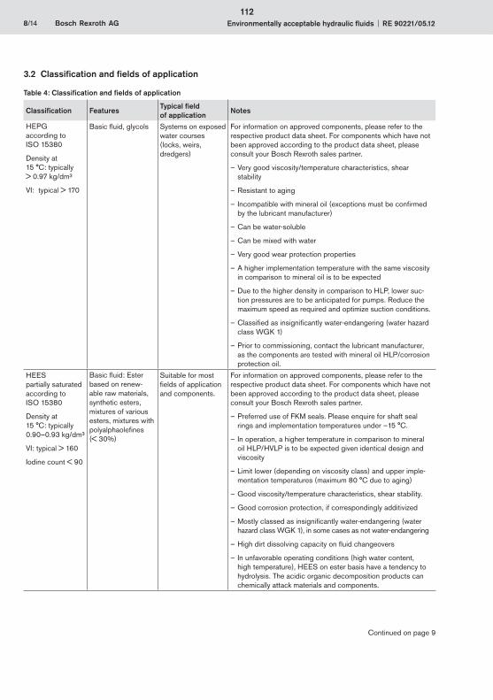
8/14 Bosch Rexroth AG Environmentally acceptable hydraulic fluids RE 90221/05.12
3.2 Classification and fields of application
Table 4: Classification and fields of application
Classification FeaturesTypical field of application
Notes
HEPGaccording to ISO 15380
Density at 15 °C: typically > 0.97 kg/dm³
VI: typical > 170
Basic fluid, glycols Systems on exposed water courses (locks, weirs, dredgers)
For information on approved components, please refer to the respective product data sheet. For components which have not been approved according to the product data sheet, please consult your Bosch Rexroth sales partner.
Very good viscosity/temperature characteristics, – shear stability
R – esistant to aging
I – ncompatible with mineral oil (exceptions must be confirmed by the lubricant manufacturer)
Can be water-soluble –
Can be mixed with water –
Very good wear protection properties –
A higher implementation temperature with the same viscosity –in comparison to mineral oil is to be expected
Due to the higher density in comparison to HLP, lower suc- –tion pressures are to be anticipated for pumps. Reduce the maximum speed as required and optimize suction conditions.
Classified as insignificantly water-endangering (water hazard –class WGK 1)
Prior to commissioning, contact the – lubricant manufacturer, as the components are tested with mineral oil HLP/corrosion protection oil.
HEESpartially saturatedaccording to ISO 15380
Density at 15 °C: typically 0.90–0.93 kg/dm³
VI: typical > 160
Iodine count < 90
Basic fluid: Ester based on renew-able raw materials, synthetic esters, mixtures of various esters, mixtures with polyalphaolefines (< 30%)
Suitable for most fields of application and components.
For information on approved components, please refer to the respective product data sheet. For components which have not been approved according to the product data sheet, please consult your Bosch Rexroth sales partner.
Preferred use of FKM seals. – Please enquire for shaft seal rings and implementation temperatures under –15 °C.
In operation, a – higher temperature in comparison to mineral oil HLP/HVLP is to be expected given identical design and viscosity
Limit lower (depending on viscosity class) and upper imple- –mentation temperatures (maximum 80 °C due to aging)
Good viscosity/temperature characteristics, – shear stability.
Good corrosion protection – , if correspondingly additivized
Mostly classed – as insignificantly water-endangering (water hazard class WGK 1), in some cases as not water-endangering
High dirt dissolving capacity on – fluid changeovers
In unfavorable operating conditions (high – water content, high temperature), HEES on ester basis have a tendency to hydrolysis. The acidic organic decomposition products can chemically attack materials and components.
Continued on page 9
112
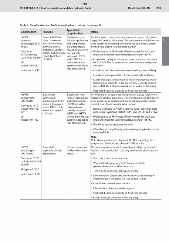
RE 90221/05.12 Environmentally acceptable hydraulic fluids Bosch Rexroth AG 9/14
Classification FeaturesTypical field of application
Notes
HEESsaturatedaccording to ISO 15380
Density at 15 °C: typically 0.90–0.93 kg/dm³
VI: typical 140–160
Iodine count <15
Basic fluid: Ester based on renew-able raw materials, synthetic esters, mixtures of various esters, mixtures with polyalphaolefines (< 30%)
Suitable for most fields of application and components. Saturated HEES should be preferred over partially saturated HEES and HETG for components and systems exposed to high stress levels.
For information on approved components, please refer to the respective product data sheet. For components which have not been approved according to the product data sheet, please consult your Bosch Rexroth sales partner.
Preferred use of FKM seals. – Please enquire for shaft seal rings and implementation temperatures under –15 °C.
In operation, a – higher temperature in comparison to mineral oil HLP/HVLP is to be expected given identical design and viscosity
Good viscosity/temperature characteristics, – shear stability
Good corrosion protection, if correspondingly additivized –
Mostly classed as insignificantly water-endangering (water –hazard class WGK 1), in the case of low viscosity classes (up to ISO VG 32) also classed as not water-endangering
High dirt dissolving capacity on – fluid changeovers
HEPRaccording to ISO 15380
Density at 15 °C: typically 0.87 kg/dm³
VI : typical 140–160
Basic fluid:synthetically manufactured hydro-carbons (polyalpha olefins PAO) partly mixed with esters ( < 30 %)
Suitable for most fields of application and components. HEPR should be preferred over partially saturated HEES and HETG for components and systems exposed to high stress levels.
For information on approved components, please refer to the respective product data sheet. For components which have not been approved according to the product data sheet, please consult your Bosch Rexroth sales partner.
Behaves similarly to HVLP- – hydraulic fluids, individual prod-ucts comply with ISO 15380 HEPR and DIN 51524-3 HVLP
Preferred use of FKM seals. – Please enquire for shaft seal rings and implementation temperatures under –15 °C.
Good viscosity-temperature behavior –
Classified as insignificantly water-endangering (water hazard –class WGK 1)
Note:Note shear stability (see chapter 4.11 "Fluid servicing, fluid analysis and filtration" and chapter 6 "Glossary")
HETG according to ISO 15380
Density at 15 °C: typically 0.90-0.93 kg/dm³
VI: typical > 200
Iodine count > 90
Basic fluid: vegetable oils and triglycerides
Not recommended for Rexroth compo-nents!
Practical requirements are frequently not fulfilled by hydraulic fluids in this classification. Use only permissible after consulta-tion.
Viscosity is – not stable over time
Very fast fluid aging, very hydrolysis-susceptible –(please observe neutralization number)
Tendency – to gumming, gelling and setting.
Limit the lower (depending on viscosity class) and upper –implementation temperatures (see chapter 3.1.5)
Only limited material compatibility –
Filterability problems at water ingress –
High dirt dissolving capacity on – fluid changeovers
Mostly classed as not water-endangering –
Table 4: Classification and fields of application (continued from page 8)
113
1

10/14 Bosch Rexroth AG Environmentally acceptable hydraulic fluids RE 90221/05.12
4.1 GeneralThe properties of hydraulic fluids can change continually during storage and operation.
Please note that the fluid standard ISO 15380 merely describes minimum requirements for hydraulic fluids in new condition at the time of filling into the bins. The operator of a hydraulic system must ensure that the hydraulic fluid remains in a utilizable condition throughout its entire period of use.
Deviations from the characteristic values are to be clarified with the lubricant manufacturer, the test labs or Bosch Rexroth.
Bosch Rexroth will accept no liability for damage to its compo-nents within the framework of the applicable liability legislation insofar as the latter is due to non-observance of the following instructions.
Please note the following aspects in operation.
4.2 Storage and handlingHydraulic fluids must be stored correctly in accordance with the instructions of the lubricant manufacturer. Avoid exposing the containers to lengthy periods of direct heat. Containers are to be stored in such a way that the risk of any foreign liquid or solid matter (e.g. water, foreign fluids or dust) ingression into the inside of the container can be ruled out. After taking hydraulic fluids from the containers, these are immediately to be properly resealed.
Recommendation:
Store containers in a dry, roofed place –
Store barrels on their sides –
Clean reservoir systems and machine reservoirs regularly –
4.3 Filling of new systemsUsually, the cleanliness levels of the hydraulic fluids as delivered do not meet the requirements of our components. Hydraulic fluids must be filtered using an appropriate filter system to minimize solid particle contamination and water in the system.
As early as possible during test operation, new systems should be filled with the selected hydraulic fluid so as to reduce the risk of accidentally mixing fluids (see chapter 4.5 "Mixing and compatibility of different hydraulic fluids"). Changing the hy-draulic medium at a later point represents significant additional costs (see following chapter).
4.4 Hydraulic fluid changeoverIn particular with the changeover from mineral oils to environ-mentally acceptable hydraulic fluids, but also from one environ-mentally acceptable hydraulic fluids to another, there may be interference (e.g. incompatibility in the form of gelling, silting, stable foam or reduced filterability or filter blockage).
In the case of changeovers of the fluid in hydraulic systems, it is important to ensure compatibility of the new hydraulic fluid with the remains of the previous hydraulic fluid. Bosch Rexroth recommends obtaining verification of compatibility from the
manufacturer or supplier of the new hydraulic fluid. The quantity of old fluid remaining should be minimized. Mixing hydraulic fluids should be avoided, see following chapter.
For information on changing over hydraulic fluids with different classifications, please refer to VDMA 24314, VDMA 24569 and ISO 15380 appendix A.
Bosch Rexroth will not accept liability for any damage to its components resulting from inadequate hydraulic fluid change-overs!
4.5 Mixing and compatibility of different hydraulic fluidsIf hydraulic fluids from different manufacturers or different types from the same manufacturer are mixed, gelling, silting and deposits may occur. These, in turn, may cause foaming, impaired air separation ability, malfunctions and damage to the hydraulic system.
If the fluid contains more than 2 % of another fluid then it is considered to be a mixture. Exceptions apply for water, see chapter 4.10 "Water".
Mixing with other hydraulic fluids is not generally permitted. This also includes hydraulic fluids with the same classification and from the market overview RE 90221-01. If individual lubri-cant manufacturers advertise miscibility and/or compatibility, this is entirely the responsibility of the lubricant manufacturer.
Bosch Rexroth customarily tests all components with mineral oil HLP before they are delivered.
Note: With connectible accessory units and mobile filtering systems, there is a considerable risk of non-permitted mixing of the hydraulic fluids!
Rexroth will not accept liability for any damage to its compo-nents resulting from mixing hydraulic fluids!
4.6 Re-additivationAdditives added at a later point in time such as colors, wear reducers, VI enhancers or anti-foam additives, may negatively affect the performance properties of the hydraulic fluid and the compatibility with our components and therefore are not permissible.
Rexroth will not accept liability for any damage to its compo-nents resulting from re-additivation!
4.7 Foaming behaviorFoam is created by rising air bubbles at the surface of hydraulic fluids in the reservoir. Foam that develops should collapse as quickly as possible.
Common hydraulic fluids in accordance with ISO 15380 are sufficiently inhibited against foam formation in new condi-tion. On account of aging and adsorption onto surfaces, the defoamer concentration may decrease over time, leading to a stable foam.
Defoamers may be re-dosed only after consultation with the lubricant manufacturer and with his written approval.
Defoamers may affect the air separation ability.
4 Hydraulic fluids in operation
114
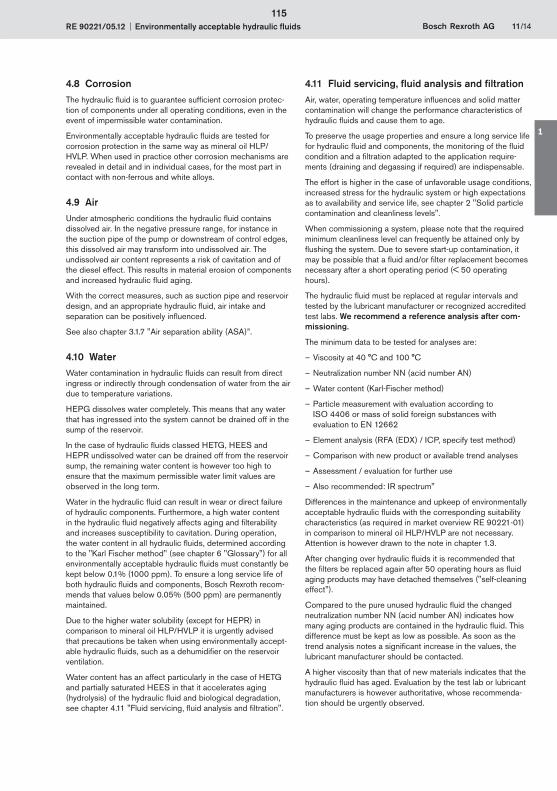
RE 90221/05.12 Environmentally acceptable hydraulic fluids Bosch Rexroth AG 11/14
4.8 CorrosionThe hydraulic fluid is to guarantee sufficient corrosion protec-tion of components under all operating conditions, even in the event of impermissible water contamination.
Environmentally acceptable hydraulic fluids are tested for corrosion protection in the same way as mineral oil HLP/HVLP. When used in practice other corrosion mechanisms are revealed in detail and in individual cases, for the most part in contact with non-ferrous and white alloys.
4.9 AirUnder atmospheric conditions the hydraulic fluid contains dissolved air. In the negative pressure range, for instance in the suction pipe of the pump or downstream of control edges, this dissolved air may transform into undissolved air. The undissolved air content represents a risk of cavitation and of the diesel effect. This results in material erosion of components and increased hydraulic fluid aging.
With the correct measures, such as suction pipe and reservoir design, and an appropriate hydraulic fluid, air intake and separation can be positively influenced.
See also chapter 3.1.7 "Air separation ability (ASA)”.
4.10 WaterWater contamination in hydraulic fluids can result from direct ingress or indirectly through condensation of water from the air due to temperature variations.
HEPG dissolves water completely. This means that any water that has ingressed into the system cannot be drained off in the sump of the reservoir.
In the case of hydraulic fluids classed HETG, HEES and HEPR undissolved water can be drained off from the reservoir sump, the remaining water content is however too high to ensure that the maximum permissible water limit values are observed in the long term.
Water in the hydraulic fluid can result in wear or direct failure of hydraulic components. Furthermore, a high water content in the hydraulic fluid negatively affects aging and filterability and increases susceptibility to cavitation. During operation, the water content in all hydraulic fluids, determined according to the "Karl Fischer method" (see chapter 6 "Glossary") for all environmentally acceptable hydraulic fluids must constantly be kept below 0.1% (1000 ppm). To ensure a long service life of both hydraulic fluids and components, Bosch Rexroth recom-mends that values below 0.05% (500 ppm) are permanently maintained.
Due to the higher water solubility (except for HEPR) in comparison to mineral oil HLP/HVLP it is urgently advised that precautions be taken when using environmentally accept-able hydraulic fluids, such as a dehumidifier on the reservoir ventilation.
Water content has an affect particularly in the case of HETG and partially saturated HEES in that it accelerates aging (hydrolysis) of the hydraulic fluid and biological degradation, see chapter 4.11 "Fluid servicing, fluid analysis and filtration".
4.11 Fluid servicing, fluid analysis and filtrationAir, water, operating temperature influences and solid matter contamination will change the performance characteristics of hydraulic fluids and cause them to age.
To preserve the usage properties and ensure a long service life for hydraulic fluid and components, the monitoring of the fluid condition and a filtration adapted to the application require-ments (draining and degassing if required) are indispensable.
The effort is higher in the case of unfavorable usage conditions, increased stress for the hydraulic system or high expectations as to availability and service life, see chapter 2 "Solid particle contamination and cleanliness levels".
When commissioning a system, please note that the required minimum cleanliness level can frequently be attained only by flushing the system. Due to severe start-up contamination, it may be possible that a fluid and/or filter replacement becomes necessary after a short operating period (< 50 operating hours).
The hydraulic fluid must be replaced at regular intervals and tested by the lubricant manufacturer or recognized accredited test labs. We recommend a reference analysis after com-missioning.
The minimum data to be tested for analyses are:
Viscosity at 40 °C and 100 °C –
Neutralization number NN (acid number AN) –
Water content (Karl-Fischer method) –
Particle measurement with evaluation according to –ISO 4406 or mass of solid foreign substances with evaluation to EN 12662
Element analysis – (RFA (EDX) / ICP, specify test method)
Comparison with new product or available trend analyses –
Assessment / evaluation for further use –
Also – recommended: IR spectrum"
Differences in the maintenance and upkeep of environmentally acceptable hydraulic fluids with the corresponding suitability characteristics (as required in market overview RE 90221-01) in comparison to mineral oil HLP/HVLP are not necessary. Attention is however drawn to the note in chapter 1.3.
After changing over hydraulic fluids it is recommended that the filters be replaced again after 50 operating hours as fluid aging products may have detached themselves ("self-cleaning effect").
Compared to the pure unused hydraulic fluid the changed neutralization number NN (acid number AN) indicates how many aging products are contained in the hydraulic fluid. This difference must be kept as low as possible. As soon as the trend analysis notes a significant increase in the values, the lubricant manufacturer should be contacted.
A higher viscosity than that of new materials indicates that the hydraulic fluid has aged. Evaluation by the test lab or lubricant manufacturers is however authoritative, whose recommenda-tion should be urgently observed.
115
1
12/14 Bosch Rexroth AG Environmentally acceptable hydraulic fluids RE 90221/05.12
On systems where the possibility of water contamination cannot be completely ruled out (also condensation), it should be ensured via the hydraulic system circuit that fluid aging products are not accumulating in individual areas of the hydraulic system, but are being removed from the system in a controlled manner via the filtration system. This should be ensured via suitable hydraulic circuits (e.g. flushing circuit) or system manufacturer's operating instructions/specifications.
In case of warranty, liability or guarantee claims to Bosch Rexroth, service verification and/or the results of fluid analyses are to be provided.
5 Disposal and environmental protection
All environmentally acceptable hydraulic fluids, are like mineral oil-based hydraulic fluids, subject to special disposal obliga-tions.
The respective lubricant manufacturers provide specifications on environmentally acceptable handling and storage. Please ensure that spilt or splashed fluids are absorbed with appropri-ate adsorbents or by a technique that prevents it contaminating water courses, the ground or sewerage systems.
It is also not permitted to mix fluids when disposing of hydraulic fluids. Regulations governing the handing of used oils stipulate that used oils are not to mixed with other products, e.g. substances containing halogen. Non-compliance will increase disposal costs. Comply with the national legal provisions concerning the disposal of the corresponding hydraulic fluid. Comply with the local safety data sheet of the lubricant manufacturer for the country concerned.
116
RE 90221/05.12 Environmentally acceptable hydraulic fluids Bosch Rexroth AG 13/14
6 Glossary
AdditivationAdditives are chemical substances added to the basic fluids to achieve or improve specific properties.
AgingHydraulic fluids age due to oxidation (see chapter 3.1.5 "Aging resistance"). Liquid and solid contamination acts as a catalyzer for aging, meaning that it needs to be minimized as far as possible by careful filtration. Please refer to Hydrolysis.
Arrhenius equationThe quantitative relation between reaction rate and temperature is described by an exponential function, the Arrhenius equation. This function is usually visualized within the typical temperature range of the hydraulic system. For a practical example, see chapter 3.1.5 "Aging resistance”.
Basic fluidsIn general, a hydraulic fluid is made up of a basic fluid, or base oil, and chemical substances, the so-called additives. The proportion of basic fluid is generally greater than 90%.
Diesel effectIf hydraulic fluid that contains air bubbles is compressed quickly, the bubbles are heated to such a degree that a self-ignition of the air-gas mix may occur. The resultant temperature increase may lead to seal damage and increased aging of the hydraulic fluid.
Saturated estersEsters differ by the number of C atoms (chain length) and position of the bonds between the C atoms. Saturated esters do not have double/multiple bonds between C atoms and are therefore more resistant to aging than partially saturated esters.
Partially saturated estersIn contrast to saturated esters, partially saturated esters have double/multiple bonds between C atoms. Rexroth defines partially saturated esters as unsaturated bonds and mixtures of esters with unsaturated and saturated bonds. Esters with unsaturated bonds are produced on the basis of renewable raw materials.
Depending on their number and position, these unsaturated bonds between the C atoms are instable. These bonds can detach themselves and form new bonds, thus changing the properties of those liquids (an aging mechanism). One of the underlying requirements for inclusion in the market overview RE 90221-01 is an aging stability characteristic. Attention is however drawn to the note in chapter 1.3.
HydrolysisHydrolysis is the splitting of a chemical bond through the reaction with water under the influence of temperature.
ICP (atomic emission spectroscopy)The ICP procedure can be used to determine various wear metals, contamination types and additives. Practically all elements in the periodic system can be detected with this method..
Iodine countThe iodine count is a yardstick for the quantity of single and multiple unsaturated bonds between C atoms in the basic fluid. A low iodine count indicates that the hydraulic fluid contains few unsaturated bonds and is thus considerably more resistant to aging than a hydraulic fluid with a high iodine count. A statement about the position at which these multiple bonds are located and about how "stable" they are against influencing factors cannot be derived simply by stating the iodine count.
Karl Fischer methodMethod to determine the water content in fluids. Indirect coulometric determination procedure in accordance with DIN EN ISO 12937 in connection with DIN 51777-2. Only the combination of both standards will assure adequately accurate measured values. For hydraulic fluids based on glycol, DIN EN ISO 12937 is to be applied in conjunction with DIN 51777-1.
CavitationCavitation is the creation of cavities in fluids due to pressure reduction below the saturated vapour pressure and subse-quent implosion when the pressure increases. When the cavities implode, extremely high acceleration, temperatures and pressure may occur temporarily, which may damage the component surfaces.
Neutralization number (NN)The neutralization number (NN) or acid number (AN) specifies the amount of caustic potash required to neutralize the acid contained in one gram of fluid.
Pour point The lowest temperature at which the fluid still just flows when cooled down under set conditions. The pour point is specified in the lubricant manufacturers' technical data sheets as a reference value for achieving this flow limit.
RFA (wavelength dispersive x-ray fluorescence analysis)Is a procedure to determine nearly all elements in liquid and solid samples with nearly any composition. This analysis method is suitable for examining additives and contamination, delivering fast results.
Shearing/shear lossShearing of molecule chains during operation can change the viscosity of hydraulic fluids with long chain VI enhancers. The initially high viscosity index drops. This needs to be taken into account when selecting the hydraulic fluid.
The only value at present that can be used to assess viscosity changes in operation is the result of the test in accordance with DIN 51350 part -6. Please note that there are practical applications that create a much higher shear load on such hydraulic fluids than can be achieved by this test.
Stick-slip Interaction between a resilient mass system involving friction (such as cylinder + oil column + load) and the pressure increase at very low sliding speeds. The static friction of the system is a decisive value here. The lower it is, the lower the speed that can still be maintained without sticking. Depend-ing on the tribologic system, the stick-slip effect may lead to vibrations generated and sometimes also to significant noise emission. In many cases, the effect can be attenuated by replacing the lubricant.
117
1

14/14 Bosch Rexroth AG Environmentally acceptable hydraulic fluids RE 90221/05.12
Bosch Rexroth AGHydraulicsZum Eisengießer 197816 Lohr am Main, GermanyPhone +49 (0) 93 52 / 18-0Fax +49 (0) 93 52 / 18-23 [email protected]
ViscosityViscosity is the measure of the internal friction of a fluid to flow. It is defined as the property of a substance to flow under tension. Viscosity is the most important characteristic for describing the load-bearing capacity of a hydraulic fluid.
Kinematic viscosity is the ratio of the dynamic viscosity and the density of the fluid; the unit is mm²/s. Hydraulic fluids are clas-sified by their kinematic viscosity into ISO viscosity classes. The reference temperature for this is 40 °C.
Viscosity index (VI)Refers to the viscosity temperature behavior of a fluid. The lower the change of viscosity in relation the temperature, the higher the VI.
© This document, as well as the data, specifications and other information set forth in it, are the exclusive property of Bosch Rexroth AG. It may not be reproduced or given to third parties without its consent.
No statements concerning the suitability of a hydraulic fluid for a specific purpose can be derived from our information. The information given does not release the user from the obligation of own judgment and verification.
It must be remembered that our products are subject to a natural process of wear and aging.
Subject to change.
118
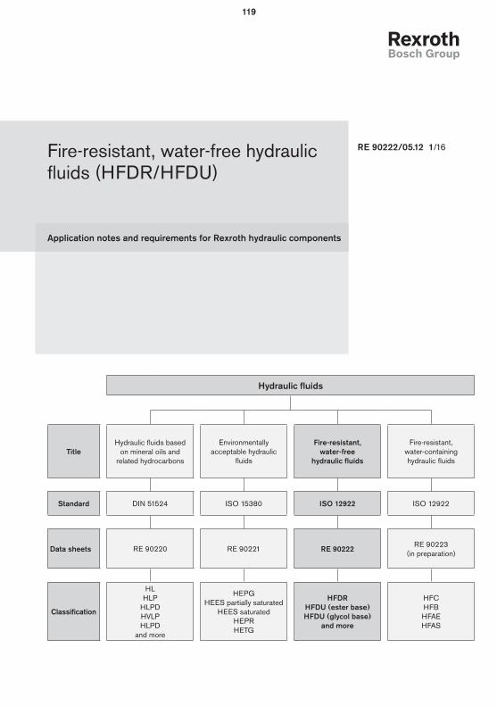
Application notes and requirements for Rexroth hydraulic components
Fire-resistant, water-free hydraulic fluids (HFDR/HFDU)
RE 90222/05.12 1/16
Hydraulic fluids
TitleHydraulic fluids based
on mineral oils and related hydrocarbons
Environmentally acceptable hydraulic
fluids
Fire-resistant, water-free
hydraulic fluids
Fire-resistant, water-containing hydraulic fluids
Standard DIN 51524 ISO 15380 ISO 12922 ISO 12922
Data sheets RE 90220 RE 90221 RE 90222 RE 90223
(in preparation)
Classification
HLHLP
HLPDHVLPHLPD
and more
HEPGHEES partially saturated
HEES saturatedHEPRHETG
HFDRHFDU (ester base)HFDU (glycol base)
and more
HFCHFBHFAEHFAS
119

2/16 Bosch Rexroth AG Fire-resistant, water-free hydraulic fluids RE 90222/05.12
Contents
1 Basic information .................................................................................................................................................................................................3
1.1 General instructions ...................................................................................................................................................................................3
1.2 Fire resistance ............................................................................................................................................................................................3
1.3 Scope ...........................................................................................................................................................................................................4
1.4 Safety instructions .....................................................................................................................................................................................4
2 Solid particle contamination and cleanliness levels .....................................................................................................................................5
3 Selection of the hydraulic fluid ..........................................................................................................................................................................6
3.1 Selection criteria for the hydraulic fluid .................................................................................................................................................6
3.1.1 Viscosity .................................................................................................................................................................................................6
3.1.2 Viscosity-temperature behavior ........................................................................................................................................................7
3.1.3 Wear protection capability ................................................................................................................................................................7
3.1.4 Material compatibility..........................................................................................................................................................................7
3.1.5 Aging resistance .................................................................................................................................................................................7
3.1.6 Environmentally acceptable ..............................................................................................................................................................8
3.1.7 Air separation ability (ASA) ...............................................................................................................................................................8
3.1.8 Demulsifying ability and water solubility ........................................................................................................................................8
3.1.9 Filterability .............................................................................................................................................................................................8
3.1.10 Corrosion protection ........................................................................................................................................................................8
3.1.11 Additivation .........................................................................................................................................................................................8
3.2 Classification and fields of application ................................................................................................................................................9
4 Hydraulic fluids in operation ...........................................................................................................................................................................11
4.1 General .......................................................................................................................................................................................................11
4.2 Storage and handling .............................................................................................................................................................................11
4.3 Filling of new systems.............................................................................................................................................................................11
4.4 Hydraulic fluid changeover ....................................................................................................................................................................11
4.5 Mixing and compatibility of different hydraulic fluids .......................................................................................................................11
4.6 Re-additivation ..........................................................................................................................................................................................11
4.7 Foaming behavior .....................................................................................................................................................................................11
4.8 Corrosion ...................................................................................................................................................................................................12
4.9 Air ................................................................................................................................................................................................................12
4.10 Water ........................................................................................................................................................................................................12
4.11 Fluid servicing, fluid analysis and filtration .......................................................................................................................................12
5 Disposal and environmental protection ........................................................................................................................................................13
6 Glossary ...............................................................................................................................................................................................................14
120
RE 90222/05.12 Fire-resistant, water-free hydraulic fluids Bosch Rexroth AG 3/16
1 Basic information
1.1 General instructionsThe hydraulic fluid is the common element in any hydraulic component and must be selected very carefully. Quality and cleanliness of the hydraulic fluid are decisive factors for the operational reliability, efficiency and service life of a system.
Hydraulic fluids must conform, be selected and used in accordance with the generally acknowledged rules of technol-ogy and safety provisions. Reference is made to the country-specific standards and directives (in Germany the directive of the Employer's Liability Insurance Association BGR 137).
This data sheet includes recommendations and regulations concerning the selection, operation and disposal of fire-resis-tant, water-free hydraulic fluids in the application of Rexroth hydraulic components.
The individual selection of hydraulic fluid or the choice of classification are the responsibility of the operator.
It is the responsibility of the user to ensure that appropriate measures are taken for safety and health protection and to ensure compliance with statutory regulations. The recommen-dations of the lubricant manufacturer and the specifications given in the safety data sheet are to be observed when using hydraulic fluid.
This data sheet does not absolve the operator from verifying the conformity and suitability of the respective hydraulic fluid for his system. He is to ensure that the selected fluid meets the minimum requirements of the relevant hydraulic fluid standard during the whole of the period of use.
The currently valid standard for fire-resistant hydraulic fluids is the ISO 12922. In addition, other, more detailed documents, guidelines, specifications and legislation may also be valid. The operator is responsible for ensuring that such regulations are observed, for example:
7th Luxembourg Report: Luxembourg, April 1994, Doc. –No. 4746/10/91 EN "Requirements and tests applicable to fire-resistant hydraulic fluids for hydrostatic and hydrokinetic power transmission and control"
VDMA 24314 – (1981-11): "Changing hydraulic fluids – guide-lines"
VDMA 24317 – (2005-11): "Fire-resistant hydraulic fluids – minimum technical requirements"
FM Approval Standard 6930 – (2009-04): "Flammability Classification of Industrial Fluids" (only available in English)
DIN Technical Report CEN/TR 14489 – (2006-01): "Selection guidelines for protecting safety, health and the environment"
We recommend that you maintain constant, close contact with lubricant manufacturers to support you in the selection, maintenance, care and analyses.
When disposing of used hydraulic fluids, apply the same care as during use.
1.2 Fire resistanceThere is no clear legal definition of fire-resistant hydraulic fluids. There are great differences regarding fire resistance. The selection is the sole responsibility of the system operator with respect to requirements (application, construction and design of the system, hottest source in the system, necessary fire protection).
Different test procedures are applied for evaluating fire resistance.
Fire resistance test procedure according to ISO 12922:
Ignition properties of spray according to ISO 15029-1 –(Spray flame persistence – hollow-cone nozzle method)
Ignition properties of spray according to ISO 15029-2 –(Stabilized flame heat release)
Wick flame persistence of fluids according to ISO 14935 –(average flame persistence)
Determination of the flammability characteristics of fluids –in contact with hot surfaces, ignition process according to ISO 20823 (ignition temperature, flame spread)
In general, fire-resistant hydraulic fluids are distinguished between water-containing fire-resistant and water-free fire-resistant hydraulic fluids. Water-containing fire-resistant hydraulic fluids are described in RE 90223.
Water-free, fire-resistant hydraulic fluid means hydraulic fluids with a water-proportion of 0.1% by volume ("Karl Fischer method", see chapter 6 "Glossary"), measured at the time of filling in the transport container.
In Europe water-free, fire-resistant hydraulic fluids are not approved for use in underground coal mining. The classification HFDU is no longer included in the VDMA 24317: 2005.
NoteIn contrast to water-containing fluids, all water-free, fire-resistant hydraulic fluids have a flash point and a fire point. Specific parameters for flash point and fire point can be found in the technical and/or safety data sheet for the hydraulic fluid concerned.
Just as much care should be taken when working with fire-resistant hydraulic fluids are with other hydraulic fluids, e.g. mineral oils. A leak from the hydraulic system must be avoided. The best and most cost-effective protection against fire and explosion is to prevent leakage with meticulous service, maintenance and care of the hydraulic system.
121
1
4/16 Bosch Rexroth AG Fire-resistant, water-free hydraulic fluids RE 90222/05.12
1.4 Safety instructionsHydraulic fluids can constitute a risk for persons and the environment. These risks are described in the hydraulic fluid safety data sheets. The operator is to ensure that a current safety data sheet for the hydraulic fluid used is available and that the measures stipulated therein are complied with.
1.3 ScopeThis data sheet must be applied when using water-free, fire-resistant hydraulic fluids with Rexroth hydraulic components. The specifications of this data sheet may be further restricted by the specifications given in data sheets for the individual components concerned.
The use of the individual water-free, fire-resistant hydraulic fluids in accordance with the intended purpose can be found in the safety data sheets or other product description documents of the lubricant manufacturers. In addition, each use is to be individually considered.
Rexroth hydraulic components may only be operated with water-free, fire-resistant hydraulic fluids according to ISO 12922 if specified in the respective component data sheet or if a Rexroth approval for use is furnished.
The manufacturers of hydraulic systems must adjust their sys-tems and operating instructions to the water-free, fire-resistant hydraulic fluids.
Bosch Rexroth will accept no liability for its components for any damage resulting from failure to comply with the notes below.
122
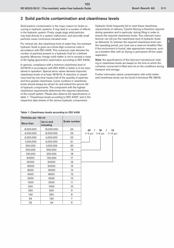
RE 90222/05.12 Fire-resistant, water-free hydraulic fluids Bosch Rexroth AG 5/16
Solid particle contamination is the major reason for faults oc-curring in hydraulic systems. It may lead to a number of effects in the hydraulic system. Firstly, single large solid particles may lead directly to a system malfunction, and secondly small particles cause continuous elevated wear.
For mineral oils, the cleanliness level of water-free, fire-resistant hydraulic fluids is given as a three-digit numerical code in accordance with ISO 4406. This numerical code denotes the number of particles present in a hydraulic fluid for a defined quantity. Moreover, foreign solid matter is not to exceed a mass of 50 mg/kg (gravimetric examination according to ISO 4405).
In general, compliance with a minimum cleanliness level of 20/18/15 in accordance with ISO 4406 or better is to be main-tained in operation. Special servo valves demand improved cleanliness levels of at least 18/16/13. A reduction in cleanli-ness level by one level means half of the quantity of particles and thus greater cleanliness. Lower numbers in cleanliness levels should always be striven for and extend the service life of hydraulic components. The component with the highest cleanliness requirements determines the required cleanliness of the overall system. Please also observe the specifications in table 1: "Cleanliness levels according to ISO 4406" and in the respective data sheets of the various hydraulic components.
Hydraulic fluids frequently fail to meet these cleanliness requirements on delivery. Careful filtering is therefore required during operation and in particular, during filling in order to ensure the required cleanliness levels. Your lubricant manu-facturer can tell you the cleanliness level of hydraulic fluids as delivered. To maintain the required cleanliness level over the operating period, you must use a reservoir breather filter. If the environment is humid, take appropriate measures, such as a breather filter with air drying or permanent off-line water separation.
Note: the specifications of the lubricant manufacturer relat-ing to cleanliness levels are based on the time at which the container concerned is filled and not on the conditions during transport and storage.
Further information about contamination with solid matter and cleanliness levels can be found in brochure RE 08016.
Table 1: Cleanliness levels according to ISO 4406
Particles per 100 ml Scale number
More than Up to and including
8,000,000 16,000,000 24
4,000,000 8,000,000 23
2,000,000 4,000,000 22
1,000,000 2,000,000 21
500,000 1,000,000 20
250,000 500,000 19
130,000 250,000 18
64000 130,000 17
32000 64000 16
16000 32000 15
8000 16000 14
4000 8000 13
2000 4000 12
1000 2000 11
500 1000 10
250 500 9
130 250 8
64 130 7
32 64 6
20 / 18 / 15 > 4 μm > 6 μm > 14 μm
2 Solid particle contamination and cleanliness levels
123
1
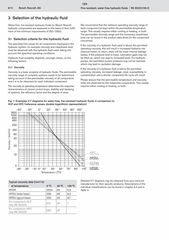
6/16 Bosch Rexroth AG Fire-resistant, water-free hydraulic fluids RE 90222/05.12
Water-free, fire-resistant hydraulic fluids for Bosch Rexroth hydraulic components are assessed on the basis of their fulfill-ment of the minimum requirements of ISO 12922.
3.1 Selection criteria for the hydraulic fluidThe specified limit values for all components employed in the hydraulic system, for example viscosity and cleanliness level, must be observed with the hydraulic fluid used, taking into account the specified operating conditions.
Hydraulic fluid suitability depends, amongst others, on the following factors:
3.1.1 Viscosity
Viscosity is a basic property of hydraulic fluids. The permissible viscosity range of complete systems needs to be determined taking account of the permissible viscosity of all components and it is to be observed for each individual component.
The viscosity at operating temperature determines the response characteristics of closed control loops, stability and damping of systems, the efficiency factor and the degree of wear.
We recommend that the optimum operating viscosity range of each component be kept within the permissible temperature range. This usually requires either cooling or heating, or both. The permissible viscosity range and the necessary cleanliness level can be found in the product data sheet for the component concerned.
If the viscosity of a hydraulic fluid used is above the permitted operating viscosity, this will result in increased hydraulic-me-chanical losses. In return, there will be lower internal leakage losses. If the pressure level is lower, lubrication gaps may not be filled up, which can lead to increased wear. For hydraulic pumps, the permitted suction pressure may not be reached, which may lead to cavitation damage.
If the viscosity of a hydraulic fluid is below the permitted operating viscosity, increased leakage, wear, susceptibility to contamination and a shorter component life cycle will result.
Please ensure that the permissible temperature and viscosity limits are observed for the respective components. This usually requires either cooling or heating, or both.
3 Selection of the hydraulic fluid
Fig. 1: Examples V-T diagrams for water-free, fire-resistant hydraulic fluids in comparison to HLP and HFC (reference values, double-logarithmic representation)
HLP46
HFC
HFDU
HFDR 40 25 10 10 30 50 90 1157005
10
4060
20
100
200
400600
10001600
0 20 40 60 80 10040 20
Temperature t [°C]
Visc
osity
[
mm
2 /s]
Typical viscosity data [mm2/s]
at temperature 0 °C 40 °C 100 °C
HFDR 2500 43 5,3
HFDU (ester base) 330 46 9,2
HFDU (glycol base) 350 46 8,7
For comparison HLP (see RE 90220)
610 46 7
For comparison HFC (see RE 90223)
280 46
Detailed V-T diagrams may be obtained from your lubricant manufacturer for their specific products. Descriptions of the individual classifications can be found in chapter 3.2 and in Table 4.
124
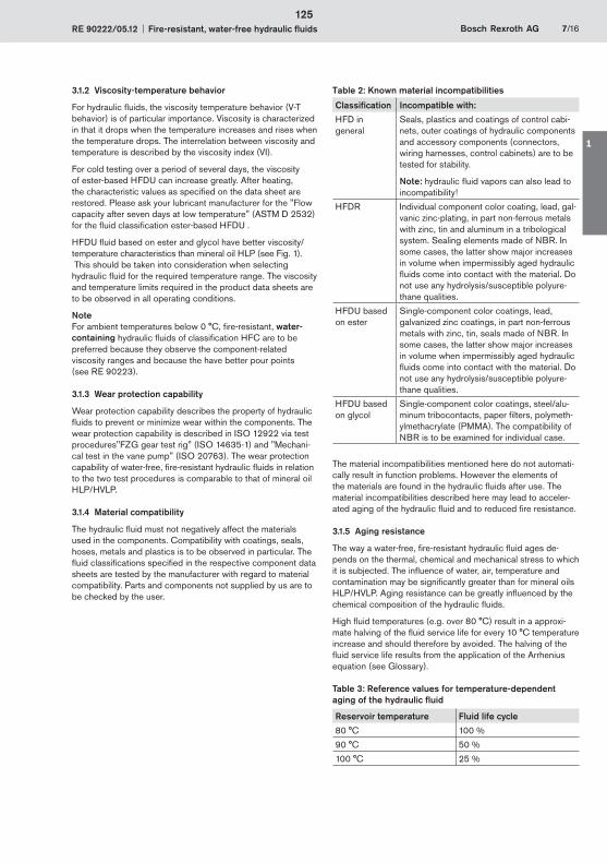
RE 90222/05.12 Fire-resistant, water-free hydraulic fluids Bosch Rexroth AG 7/16
3.1.2 Viscosity-temperature behavior
For hydraulic fluids, the viscosity temperature behavior (V-T behavior) is of particular importance. Viscosity is characterized in that it drops when the temperature increases and rises when the temperature drops. The interrelation between viscosity and temperature is described by the viscosity index (VI).
For cold testing over a period of several days, the viscosity of ester-based HFDU can increase greatly. After heating, the characteristic values as specified on the data sheet are restored. Please ask your lubricant manufacturer for the "Flow capacity after seven days at low temperature" (ASTM D 2532) for the fluid classification ester-based HFDU .
HFDU fluid based on ester and glycol have better viscosity/temperature characteristics than mineral oil HLP (see Fig. 1). This should be taken into consideration when selecting hydraulic fluid for the required temperature range. The viscosity and temperature limits required in the product data sheets are to be observed in all operating conditions.
Note For ambient temperatures below 0 °C, fire-resistant, water-containing hydraulic fluids of classification HFC are to be preferred because they observe the component-related viscosity ranges and because the have better pour points (see RE 90223).
3.1.3 Wear protection capability
Wear protection capability describes the property of hydraulic fluids to prevent or minimize wear within the components. The wear protection capability is described in ISO 12922 via test procedures"FZG gear test rig" (ISO 14635-1) and "Mechani-cal test in the vane pump" (ISO 20763). The wear protection capability of water-free, fire-resistant hydraulic fluids in relation to the two test procedures is comparable to that of mineral oil HLP/HVLP.
3.1.4 Material compatibility
The hydraulic fluid must not negatively affect the materials used in the components. Compatibility with coatings, seals, hoses, metals and plastics is to be observed in particular. The fluid classifications specified in the respective component data sheets are tested by the manufacturer with regard to material compatibility. Parts and components not supplied by us are to be checked by the user.
Table 2: Known material incompatibilities
Classification Incompatible with:
HFD in general
Seals, plastics and coatings of control cabi-nets, outer coatings of hydraulic components and accessory components (connectors, wiring harnesses, control cabinets) are to be tested for stability.
Note: hydraulic fluid vapors can also lead to incompatibility!
HFDR Individual component color coating, lead, gal-vanic zinc-plating, in part non-ferrous metals with zinc, tin and aluminum in a tribological system. Sealing elements made of NBR. In some cases, the latter show major increases in volume when impermissibly aged hydraulic fluids come into contact with the material. Do not use any hydrolysis/susceptible polyure-thane qualities.
HFDU based on ester
Single-component color coatings, lead, galvanized zinc coatings, in part non-ferrous metals with zinc, tin, seals made of NBR. In some cases, the latter show major increases in volume when impermissibly aged hydraulic fluids come into contact with the material. Do not use any hydrolysis/susceptible polyure-thane qualities.
HFDU based on glycol
Single-component color coatings, steel/alu-minum tribocontacts, paper filters, polymeth-ylmethacrylate (PMMA). The compatibility of NBR is to be examined for individual case.
The material incompatibilities mentioned here do not automati-cally result in function problems. However the elements of the materials are found in the hydraulic fluids after use. The material incompatibilities described here may lead to acceler-ated aging of the hydraulic fluid and to reduced fire resistance.
3.1.5 Aging resistance
The way a water-free, fire-resistant hydraulic fluid ages de-pends on the thermal, chemical and mechanical stress to which it is subjected. The influence of water, air, temperature and contamination may be significantly greater than for mineral oils HLP/HVLP. Aging resistance can be greatly influenced by the chemical composition of the hydraulic fluids.
High fluid temperatures (e.g. over 80 °C) result in a approxi-mate halving of the fluid service life for every 10 °C temperature increase and should therefore by avoided. The halving of the fluid service life results from the application of the Arrhenius equation (see Glossary).
Table 3: Reference values for temperature-dependent aging of the hydraulic fluid
Reservoir temperature Fluid life cycle
80 °C 100 %
90 °C 50 %
100 °C 25 %
125
1
8/16 Bosch Rexroth AG Fire-resistant, water-free hydraulic fluids RE 90222/05.12
A modified aging test (ISO 4263-3 or ASTM D943 – without the addition of water) is specified for fluid classification HFDU. Fluid classification HFDR is described with a special procedure with respect to oxidation stability (EN 14832) and oxidation service life (ISO 4263-3). The calculated fluid service life is derived from the results of tests in which the long-term characteristics are simulated in a short period of time by applying more arduous conditions (condensed testing). This calculated fluid service life is not to be equated to the fluid service life in real-life applications.
Table 3 is a practical indicator for hydraulic fluids with water content < 0.1%, cf. chapter 4.10. "Water".
3.1.6 Environmentally acceptable
HFDU fluids based on ester and glycol are hydraulic fluids which may also be classified as environmentally acceptable. The main criteria for fire-resistant, water-free hydraulic fluids are the leak-free, technically problem-free use and the neces-sary fire resistance. Environmentally acceptable is merely a supplementary criterion. Notes on environmentally compatible hydraulic fluids can be found in RE 90221.
3.1.7 Air separation ability (ASA)
The air separation ability (ASA) describes the property of a hydraulic fluid to separate undissolved air. Hydraulic fluids always contain dissolved air. During operation, dissolved air may be transformed into undissolved air, leading to cavitation damages. Fluid classification, fluid product, reservoir size and design must be coordinated to take into account the dwell time and ASA value of the hydraulic fluid. The air separation capacity depends on the viscosity, temperature, basic fluid and aging. It cannot be improved by additives.
According to ISO 12922 for instance, an ASA value 15 min-utes is required for viscosity class ISO VG 46, practical values on delivery are < 10 minutes, lower values are preferable.
3.1.8 Demulsifying ability and water solubility
The capacity of a hydraulic fluid to separate water at a defined temperature is known as the demulsifying ability. ISO 6614 defines the demulsifying properties of hydraulic fluids.
The fluid classifications HFDU based on ester and HFDR separate water, but HFD hydraulic fluids have a different water separation ability to mineral oil HLP/HVLP. At 20 °C, in comparison to mineral oil HLP/HVLP, a multiple (> factor 3) of water can separate in the hydraulic fluid. Water solubility is also more temperature-dependent than for mineral oils. The fluid classification HFDU based on glycol usually dissolves water completely, see chapter "4.10 Water".
3.1.9 Filterability
Filterability describes the ability of a hydraulic fluid to pass through a filter, removing solid contaminants. The hydraulic fluids used require a good filterability, not just when new, but also during the whole of their service life. This can differ greatly depending on the different basic fluids (glycols, esters) and additives (VI enhancers, anti-fogging additives).
The filterability is a basic prerequisite for cleanliness, servicing and filtration of hydraulic fluids. Rexroth therefore requires the same degree of filterability of water-free, fire-resistant hydraulic fluids as for mineral oils HLP/HVLP to DIN 51524. As ISO 12922 does not comment on the filterability of hydrau-lic fluids, filterability comparable to that of mineral oils HLP/HVLP must be requested of lubricant manufacturers.
Filterability is tested with the new hydraulic fluid and after the addition of 0.2 % water. The underlying standard (ISO 13357-1/-2) stipulates that filterability must have no negative effects on the filters or the hydraulic fluid, see chapter 4 "Hydraulic fluids in operation".
3.1.10 Corrosion protection
Hydraulic fluids should not just prevent corrosion formation on steel components, they must also be compatible with non-ferrous metals and alloys. Corrosion protection tests on different metals and metal alloys are described in ISO 12922.
Rexroth components are usually tested with HLP hydraulic fluids or corrosion protection oils based on mineral oils before they are delivered.
3.1.11 Additivation
The properties described above can be modified with the help of suitable additives.Bosch Rexroth does not prescribe any specific additive system.
126
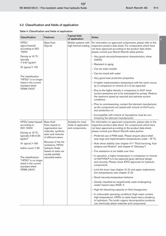
RE 90222/05.12 Fire-resistant, water-free hydraulic fluids Bosch Rexroth AG 9/16
3.2 Classification and fields of application
Table 4: Classification and fields of application
Classification FeaturesTypical field of application
Notes
HFDU (glycol-based)according to ISO 12922
Density at 15 °C: typically > 0.97 kg/dm³
VI: typical > 170
The classification "HFDU" is no longer listed in the current standard sheet VDMA 24317.
Base fluid: Glycols
Mobile systems with high thermal loading
For information on approved components, please refer to the respective product data sheet. For components which have not been approved according to the product data sheet, please consult your Bosch Rexroth sales partner.
Very good viscosity/temperature characteristics, – shear stability
Resistant to aging –
Can be water-soluble –
Can be mixed with water –
Very good wear protection properties –
A higher implementation temperature with the same viscos- –ity in comparison to mineral oil is to be expected
Due to the higher density in comparison to HLP, lower –suction pressures are to be anticipated for pumps. Reduce the maximum speed as required and optimize suction conditions.
Prior to commissioning, contact the lubricant manufacturer, –as the components are tested with mineral oil HLP/corro-sion protection oil.
Incompatible with mineral oil (exceptions must be con- –firmed by the lubricant manufacturer).
HFDU (ester-based) according to ISO 12922
Density at 15 °C: typically 0.90-0.93 kg/dm³
VI: typical > 160
Iodine count < 90
The classification "HFDU" is no longer listed in the current standard sheet VDMA 24317.
Base fluid: Ester based on regenerative raw materials, synthetic ester and mixtures of different esters
Because of the fire resistance, HFDU hydraulic fluids based on ester are usually partially saturated esters
Suitable for most fields of application and components.
For information on approved components, please refer to the respective product data sheet. For components which have not been approved according to the product data sheet, please consult your Bosch Rexroth sales partner.
Preferred use of – FKM seals. Please enquire about shaft seal rings and implementation temperatures under –15 °C.
Note shear stability – (see chapter 4.11 "Fluid servicing, fluid analysis and filtration" and chapter 6 "Glossary")
Fire resistance is not stable over time –
In operation, a higher temperature in comparison to mineral –oil HLP/HVLP is to be expected given identical design and viscosity. Please check ATEX approvals for hydraulic components.
Limit the lower (see chapter 3.1.2) and upper implementa- –tion temperatures (see chapter 3.1.5)
Good viscosity-temperature behavior –
Usually classified as insignificantly water-endangering –(water hazard class WGK 1)
High dirt dissolving capacity on – fluid changeovers
In unfavorable operating conditions (high – water content, high temperature), HFDU on ester basis have a tendency to hydrolysis. The acidic organic decomposition products can chemically attack materials and components.
127
1
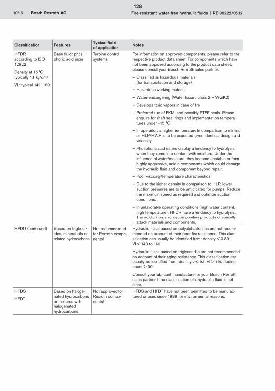
10/16 Bosch Rexroth AG Fire-resistant, water-free hydraulic fluids RE 90222/05.12
Classification FeaturesTypical field of application
Notes
HFDRaccording to ISO 12922
Density at 15 °C:typically 1.1 kg/dm³
VI : typical 140–160
Base fluid: phos-phoric acid ester
Turbine control systems
For information on approved components, please refer to the respective product data sheet. For components which have not been approved according to the product data sheet, please consult your Bosch Rexroth sales partner.
Classified as hazardous materials –(for transportation and storage)
Hazardous working material –
Water-endangering ( – Water hazard class 2 – WGK2)
Develops toxic vapors in case of fire –
Preferred use of FKM, and possibly PTFE seals. – Please enquire for shaft seal rings and implementation tempera-tures under –15 °C.
In operation, a higher temperature in comparison to mineral –oil HLP/HVLP is to be expected given identical design and viscosity
Phosphoric acid esters display a tendency to hydrolysis –when they come into contact with moisture. Under the influence of water/moisture, they become unstable or form highly aggressive, acidic components which could damage the hydraulic fluid and component beyond repair.
Poor viscosity/temperature characteristics –
Due to the higher density in comparison to HLP, lower –suction pressures are to be anticipated for pumps. Reduce the maximum speed as required and optimize suction conditions.
In unfavorable operating conditions (high – water content, high temperature), HFDR have a tendency to hydrolysis. The acidic inorganic decomposition products chemically attack materials and components.
HFDU (continued) Based on triglycer-ides, mineral oils or related hydrocarbons
Not recommended for Rexroth compo-nents!
Hydraulic fluids based on polyalphaolefines are not recom-mended on account of their poor fire resistance. This clas-sification can usually be identified from: density < 0.89; VI < 140 to 160
Hydraulic fluids based on triglycerides are not recommended on account of their aging resistance. This classification can usually be identified from: density > 0.92; VI > 190; iodine count > 90
Consult your lubricant manufacturer or your Bosch Rexroth sales partner if the classification of a hydraulic fluid is not clear.
HFDS
HFDT
Based on haloge-nated hydrocarbons or mixtures with halogenated hydrocarbons
Not approved for Rexroth compo-nents!
HFDS and HFDT have not been permitted to be manufac-tured or used since 1989 for environmental reasons.
128

RE 90222/05.12 Fire-resistant, water-free hydraulic fluids Bosch Rexroth AG 11/16
4.1 GeneralThe properties of hydraulic fluids can change continually during storage and operation.
Please note that the fluid standard ISO 12922 merely describes minimum requirements for hydraulic fluids in new condition at the time of filling into the bins. The operator of a hydraulic system must ensure that the hydraulic fluid remains in a utilizable condition throughout its entire period of use.
Deviations from the characteristic values are to be clarified with the lubricant manufacturer, the test labs or Bosch Rexroth.
Bosch Rexroth will accept no liability for damage to its compo-nents within the framework of the applicable liability legislation insofar as the latter is due to non-observance of the following instructions.
Please note the following aspects in operation.
4.2 Storage and handlingHydraulic fluids must be stored correctly in accordance with the instructions of the lubricant manufacturer. Avoid exposing the containers to lengthy periods of direct heat. Containers are to be stored in such a way that the risk of any foreign liquid or solid matter (e.g. water, foreign fluids or dust) ingression into the inside of the container can be ruled out. After taking hydraulic fluids from the containers, these are immediately to be properly resealed.
Recommendation:
Store containers in a dry, roofed place –
Store barrels on their sides –
Clean reservoir systems and machine reservoirs regularly –
4.3 Filling of new systemsUsually, the cleanliness levels of the hydraulic fluids as delivered do not meet the requirements of our components. Hydraulic fluids must be filtered using an appropriate filter system to minimize solid particle contamination and water in the system.
As early as possible during test operation, new systems should be filled with the selected hydraulic fluid so as to reduce the risk of accidentally mixing fluids (see chapter 4.5 "Mixing and compatibility of different hydraulic fluids"). Changing the hy-draulic medium at a later point represents significant additional costs (see following chapter).
4.4 Hydraulic fluid changeoverProblems may be encountered in particular when changing over from water-containing, fire-resistant hydraulic fluid or mineral oils to water-free, fire-resistant hydraulic fluids (e.g. incompatibilities in the form of gelling, silting, stable foam, reduced filterability or filter blockage). This may also happen when changing products within the same classification.
In the case of changeovers of the fluid in hydraulic systems, it is important to ensure compatibility of the new hydraulic fluid with the remains of the previous hydraulic fluid. Bosch Rexroth recommends obtaining verification of compatibility from the
manufacturer or supplier of the new hydraulic fluid. The quantity of old fluid remaining should be minimized. Mixing hydraulic fluids should be avoided, see following chapter.
Information about changing to a hydraulic fluid of a different classification can be found, for example, in VDMA 24314 and in ISO 7745. In addition, the information given in chapter 3.1.4 "Material compatibility" is also to be observed.
Bosch Rexroth will not accept liability for any damage to its com-ponents resulting from inadequate hydraulic fluid changeovers!
4.5 Mixing and compatibility of different hydraulic fluidsIf hydraulic fluids from different manufacturers or different types from the same manufacturer are mixed, gelling, silting and deposits may occur. These, in turn, may cause foaming, impaired air separation ability, malfunctions and damage to the hydraulic system.
If the fluid contains more than 2 % of another fluid then it is considered to be a mixture. Exceptions apply for water, see chapter 4.10 "Water".
Mixing with other hydraulic fluids is not generally permitted. This includes hydraulic fluids with the same classification. If individual lubricant manufacturers advertise miscibility and/or compatibility, this is entirely the responsibility of the lubricant manufacturer.
Bosch Rexroth customarily tests all components with mineral oil HLP before they are delivered.
Note: With connectible accessory units and mobile filtering systems, there is a considerable risk of non-permitted mixing of the hydraulic fluids!
Rexroth will not accept liability for any damage to its compo-nents resulting from mixing hydraulic fluids!
4.6 Re-additivationAdditives added at a later point in time such as colors, wear reducers, VI enhancers or anti-foam additives, may negatively affect the performance properties of the hydraulic fluid and the compatibility with our components and therefore are not permissible.
Rexroth will not accept liability for any damage to its compo-nents resulting from re-additivation!
4.7 Foaming behaviorFoam is created by rising air bubbles at the surface of hydraulic fluids in the reservoir. Foam that develops should collapse as quickly as possible.
Common hydraulic fluids in accordance with ISO 12922 are sufficiently inhibited against foam formation in new condi-tion. On account of aging and adsorption onto surfaces, the defoamer concentration may decrease over time, leading to a stable foam.
Defoamers may be re-dosed only after consultation with the lubricant manufacturer and with his written approval.
Defoamers may affect the air separation ability.
4 Hydraulic fluids in operation
129
1
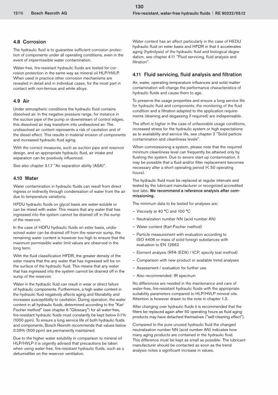
12/16 Bosch Rexroth AG Fire-resistant, water-free hydraulic fluids RE 90222/05.12
4.8 CorrosionThe hydraulic fluid is to guarantee sufficient corrosion protec-tion of components under all operating conditions, even in the event of impermissible water contamination.
Water-free, fire-resistant hydraulic fluids are tested for cor-rosion protection in the same way as mineral oil HLP/HVLP. When used in practice other corrosion mechanisms are revealed in detail and in individual cases, for the most part in contact with non-ferrous and white alloys.
4.9 AirUnder atmospheric conditions the hydraulic fluid contains dissolved air. In the negative pressure range, for instance in the suction pipe of the pump or downstream of control edges, this dissolved air may transform into undissolved air. The undissolved air content represents a risk of cavitation and of the diesel effect. This results in material erosion of components and increased hydraulic fluid aging.
With the correct measures, such as suction pipe and reservoir design, and an appropriate hydraulic fluid, air intake and separation can be positively influenced.
See also chapter 3.1.7 "Air separation ability (ASA)”.
4.10 WaterWater contamination in hydraulic fluids can result from direct ingress or indirectly through condensation of water from the air due to temperature variations.
HFDU hydraulic fluids on glycol basis are water-soluble or can be mixed with water. This means that any water that has ingressed into the system cannot be drained off in the sump of the reservoir.
In the case of HDFU hydraulic fluids on ester basis, undis-solved water can be drained off from the reservoir sump, the remaining water content is however too high to ensure that the maximum permissible water limit values are observed in the long term.
With the fluid classification HFDR, the greater density of the ester means that the any water that has ingressed will be on the surface of the hydraulic fluid. This means that any water that has ingressed into the system cannot be drained off in the sump of the reservoir.
Water in the hydraulic fluid can result in wear or direct failure of hydraulic components. Furthermore, a high water content in the hydraulic fluid negatively affects aging and filterability and increases susceptibility to cavitation. During operation, the water content in all hydraulic fluids, determined according to the "Karl Fischer method" (see chapter 6 "Glossary") for all water-free, fire-resistant hydraulic fluids must constantly be kept below 0.1% (1000 ppm). To ensure a long service life of both hydraulic fluids and components, Bosch Rexroth recommends that values below 0.05% (500 ppm) are permanently maintained.
Due to the higher water solubility in comparison to mineral oil HLP/HVLP it is urgently advised that precautions be taken when using water-free, fire-resistant hydraulic fluids, such as a dehumidifier on the reservoir ventilation.
Water content has an affect particularly in the case of HEDU hydraulic fluid on ester basis and HFDR in that it accelerates aging (hydrolysis) of the hydraulic fluid and biological degra-dation, see chapter 4.11 "Fluid servicing, fluid analysis and filtration".
4.11 Fluid servicing, fluid analysis and filtrationAir, water, operating temperature influences and solid matter contamination will change the performance characteristics of hydraulic fluids and cause them to age.
To preserve the usage properties and ensure a long service life for hydraulic fluid and components, the monitoring of the fluid condition and a filtration adapted to the application require-ments (draining and degassing if required) are indispensable.
The effort is higher in the case of unfavorable usage conditions, increased stress for the hydraulic system or high expectations as to availability and service life, see chapter 2 "Solid particle contamination and cleanliness levels".
When commissioning a system, please note that the required minimum cleanliness level can frequently be attained only by flushing the system. Due to severe start-up contamination, it may be possible that a fluid and/or filter replacement becomes necessary after a short operating period (< 50 operating hours).
The hydraulic fluid must be replaced at regular intervals and tested by the lubricant manufacturer or recognized accredited test labs. We recommend a reference analysis after com-missioning.
The minimum data to be tested for analyses are:
Viscosity at 40 °C and 100 °C –
Neutralization number NN (acid number AN) –
Water content (Karl-Fischer method) –
Particle measurement with evaluation according to –ISO 4406 or mass of solid foreign substances with evaluation to EN 12662
Element analysis (RFA (EDX) / ICP, specify test method) –
Comparison with new product or available trend analyses –
Assessment / evaluation for further use –
Also recommended: IR spectrum –
No differences are needed in the maintenance and care of water-free, fire-resistant hydraulic fluids with the appropriate suitability parameters compared to HLP/HVLP mineral oils. Attention is however drawn to the note in chapter 1.3.
After changing over hydraulic fluids it is recommended that the filters be replaced again after 50 operating hours as fluid aging products may have detached themselves ("self-cleaning effect").
Compared to the pure unused hydraulic fluid the changed neutralization number NN (acid number AN) indicates how many aging products are contained in the hydraulic fluid. This difference must be kept as small as possible. The lubricant manufacturer should be contacted as soon as the trend analysis notes a significant increase in values.
130

RE 90222/05.12 Fire-resistant, water-free hydraulic fluids Bosch Rexroth AG 13/16
A higher viscosity than that of new materials indicates that the hydraulic fluid has aged. Evaluation by the test lab or lubricant manufacturers is however authoritative, whose recommenda-tion should be urgently observed.
On systems where the possibility of water contamination cannot be completely ruled out (also condensation), it should be ensured via the hydraulic system circuit that fluid aging products are not accumulating in individual areas of the hydraulic system, but are being removed from the system in a controlled manner via the filtration system. This should be ensured via suitable hydraulic circuits (e.g. flushing circuit) or system manufacturer's operating instructions/specifications.
In case of warranty, liability or guarantee claims to Bosch Rexroth, service verification and/or the results of fluid analyses are to be provided.
5 Disposal and environmental protection
All water-free, fire-resistant hydraulic fluids, are, like mineral oil-based hydraulic fluids, subject to special disposal obligations.
The respective lubricant manufacturers provide specifications on environmentally acceptable handling and storage. Please ensure that spilt or splashed fluids are absorbed with appropri-ate adsorbents or by a technique that prevents it contaminating water courses, the ground or sewerage systems.
It is also not permitted to mix fluids when disposing of hydraulic fluids. Regulations governing the handing of used oils stipulate that used oils are not to mixed with other products, e.g. substances containing halogen. Non-compliance will increase disposal costs. Comply with the national legal provisions concerning the disposal of the corresponding hydraulic fluid. Comply with the local safety data sheet of the lubricant manufacturer for the country concerned.
131
1

14/16 Bosch Rexroth AG Fire-resistant, water-free hydraulic fluids RE 90222/05.12
6 Glossary
AdditivationAdditives are chemical substances added to the basic fluids to achieve or improve specific properties.
AgingHydraulic fluids age due to oxidation (see chapter 3.1.5 "Aging resistance"). Liquid and solid contamination acts as a catalyzer for aging, meaning that it needs to be minimized as far as possible by careful filtration. Please refer to Hydrolysis.
Arrhenius equationThe quantitative relation between reaction rate and temperature is described by an exponential function, the Arrhenius equation. This function is usually visualized within the typical temperature range of the hydraulic system. For a practical example, see chapter 3.1.5 "Aging resistance”.
Basic fluidsIn general, a hydraulic fluid is made up of a basic fluid, or base oil, and chemical substances, the so-called additives. The proportion of basic fluid is generally greater than 90%.
Diesel effect
If hydraulic fluid that contains air bubbles is compressed quickly, the bubbles are heated to such a degree that a self-ignition of the air-gas mix may occur. The resultant temperature increase may lead to seal damage and increased aging of the hydraulic fluid.
Partially saturated estersIn contrast to saturated esters, partially saturated esters have double/multiple bonds between C atoms. Rexroth defines partially saturated esters as unsaturated bonds and mixtures of esters with unsaturated and saturated bonds. Esters with unsaturated bonds are produced on the basis of renewable raw materials.
Depending on their number and position, these unsaturated bonds between the C atoms are instable. These bonds can detach themselves and form new bonds, thus changing the properties of those liquids (an aging mechanism). Attention is however drawn to the note in chapter 1.3.
HydrolysisHydrolysis is the splitting of a chemical bond through the reaction with water under the influence of temperature.
ICP (atomic emission spectroscopy)The ICP procedure can be used to determine various wear metals, contamination types and additives. Practically all elements in the periodic system can be detected with this method.
Iodine countThe iodine count is a yardstick for the quantity of single and multiple unsaturated bonds between C atoms in the basic fluid. A low iodine count indicates that the hydraulic fluid contains few unsaturated bonds and is thus considerably more resistant to aging than a hydraulic fluid with a high iodine count. A statement about the position at which these multiple bonds are located and about how "stable" they are against influencing factors cannot be derived simply by stating the iodine count.
Karl Fischer methodMethod to determine the water content in fluids. Indirect coulometric determination procedure in accordance with DIN EN ISO 12937 in connection with DIN 51777-2. Only the combination of both standards will assure adequately accurate measured values. For hydraulic fluids based on glycol, DIN EN ISO 12937 is to be applied in conjunction with DIN 51777-1.
CavitationCavitation is the creation of cavities in fluids due to pressure reduction below the saturated vapour pressure and subse-quent implosion when the pressure increases. When the cavities implode, extremely high acceleration, temperatures and pressure may occur temporarily, which may damage the component surfaces.
Neutralization number (NN)The neutralization number (NN) or acid number (AN) specifies the amount of caustic potash required to neutralize the acid contained in one gram of fluid.
Pour point The lowest temperature at which the fluid still just flows when cooled down under set conditions. The pour point is specified in the lubricant manufacturers' technical data sheets as a reference value for achieving this flow limit.
RFA (wavelength dispersive x-ray fluorescence analysis)Is a procedure to determine nearly all elements in liquid and solid samples with nearly any composition. This analysis method is suitable for examining additives and contamination, delivering fast results.
Shearing/shear lossShearing of molecule chains during operation can change the viscosity of hydraulic fluids with long chain VI enhancers and anti-fogging additives. The initially high viscosity index drops. This needs to be taken into account when selecting the hydraulic fluid.
The only value at present that can be used to assess viscosity changes in operation is the result of the test in accordance with DIN 51350 part -6. Please note that there are practical applications that create a much higher shear load on such hydraulic fluids than can be achieved by this test.
ViscosityViscosity is the measure of the internal friction of a fluid to flow. It is defined as the property of a substance to flow under tension. Viscosity is the most important characteristic for describing the load-bearing capacity of a hydraulic fluid.
Kinematic viscosity is the ratio of the dynamic viscosity and the density of the fluid; the unit is mm²/s. Hydraulic fluids are clas-sified by their kinematic viscosity into ISO viscosity classes. The reference temperature for this is 40 °C.
Viscosity index (VI)Refers to the viscosity temperature behavior of a fluid. The lower the change of viscosity in relation the temperature, the higher the VI.
132

RE 90222/05.12 Fire-resistant, water-free hydraulic fluids Bosch Rexroth AG 15/16133
1

16/16 Bosch Rexroth AG Fire-resistant, water-free hydraulic fluids RE 90222/05.12
Bosch Rexroth AGHydraulicsZum Eisengießer 197816 Lohr am Main, GermanyPhone +49 (0) 93 52 / 18-0Fax +49 (0) 93 52 / 18-23 [email protected]
© This document, as well as the data, specifications and other information set forth in it, are the exclusive property of Bosch Rexroth AG. It may not be reproduced or given to third parties without its consent.
The data specified above only serve to describe the product. No statements concerning a certain condition or suitability for a certain application can be derived from our information. The information given does not release the user from the obligation of own judgment and verification.
It must be remembered that our products are subject to a natural process of wear and aging.
Subject to change.
134
Designation TypePiston-Ø
in mm SeriesNominal pressure
in bar Data sheet Page
RE 00112-10, Edition: 2013-12, Bosch Rexroth AG
Cylinders
Contents | Cylinders | Explosion protection
Mill type cylindersHydraulic cylinders for potentially explosive atmospheres
CDH2...X. / CGH2...X
40 ... 320 1X 250 17334-X 1371
2
3
4
5
6
135
2

Bosch Rexroth AG, RE 00112-10, Edition: 2013-12
136
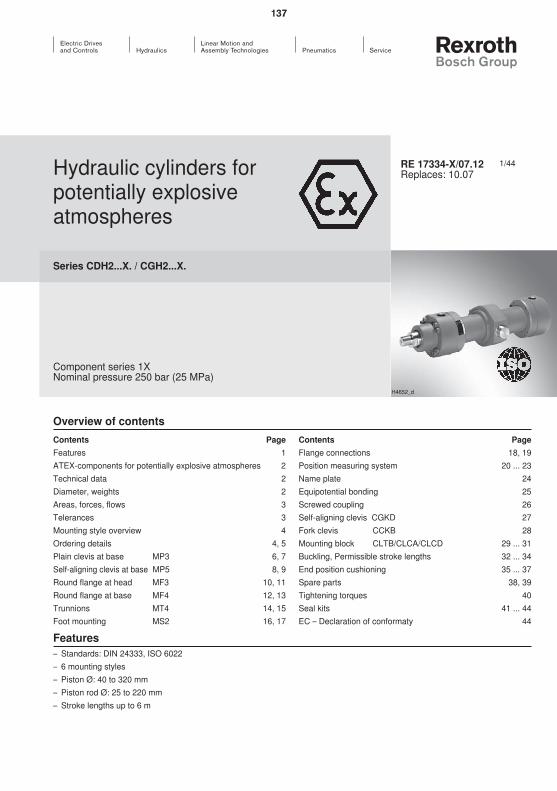
137
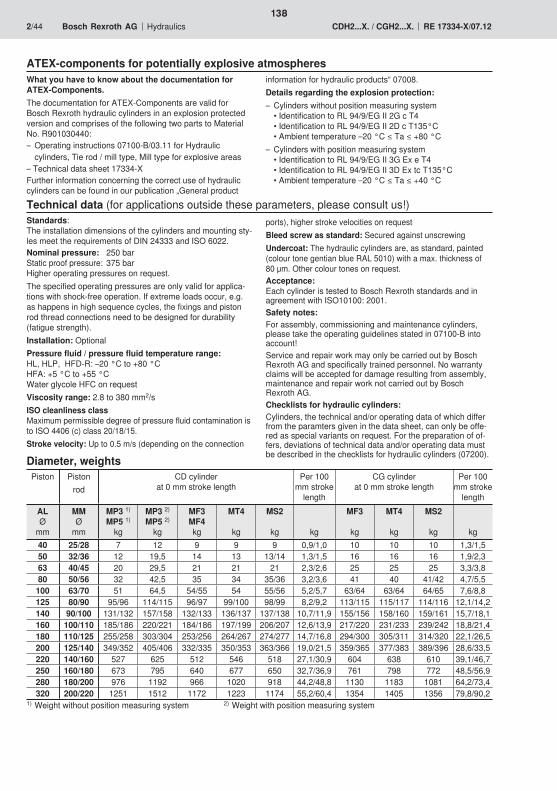
138
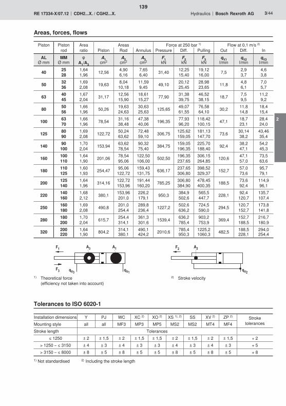
��
�� ���
�� ��
���
�� ��
���
139
2
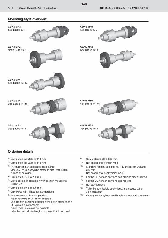
140
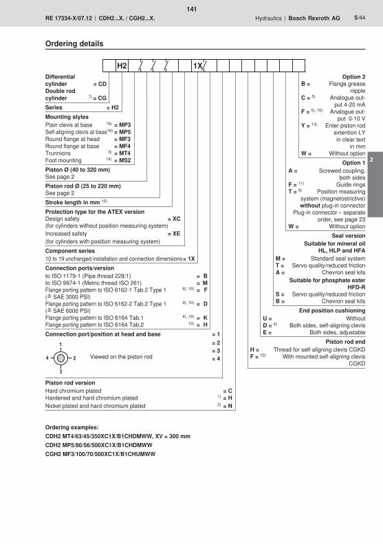
�
�
�
141
2

�
��
��
�
�� ��
�
��
��
� �������
��������
����
����
����
��
����
��
�
��
�� ��
��
���
���
�
� ��
��
����
��
�!�
������
���
��
�
��������
142

143
2
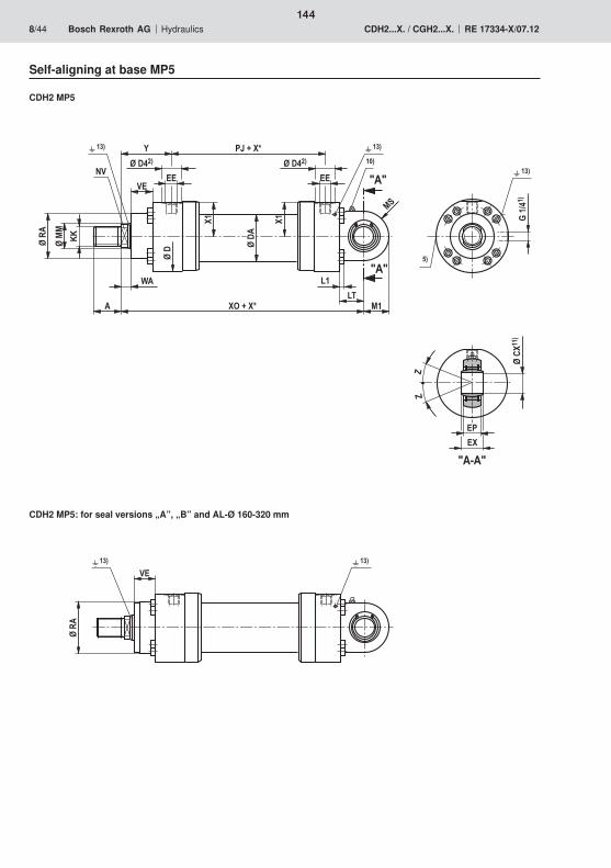
�
��
��
�
�� ��
�
��
��
� �"�����
��������
����
����
����
��
����
��
�
��
�� ��
�#
���
�$��
�
� ��
��
��
��
����
%%
�!�
������
���
��
�
��������
144
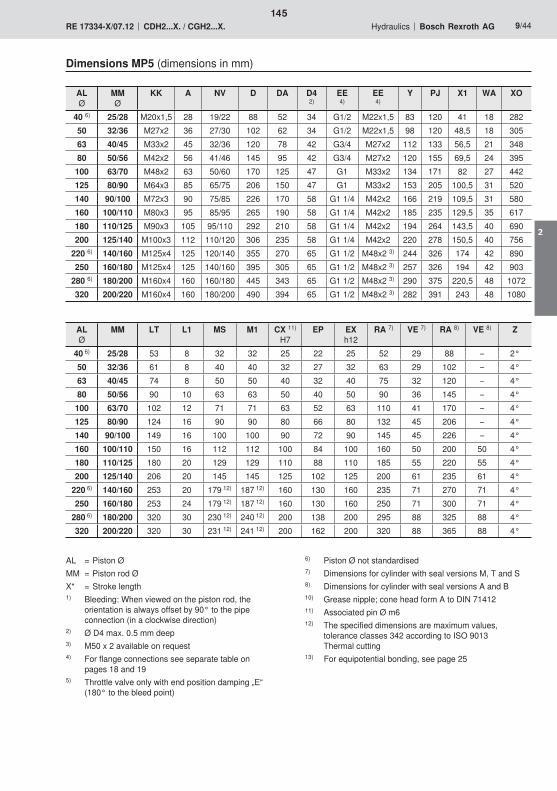
145
2
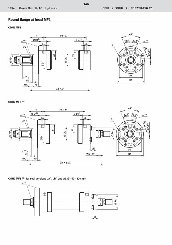
��
��
�
���
���
��
�
�� ��
�
��
�
��������
����
����
����
��
����
��
�
�� ����
&�
�'
%'�����
��
�� ��
(
��)( ��)( ������
���
��
�
�� ��
�
��
�
��������
����
��
����
��
����
��
�
�� ��
��
&�
�'
%������*���
��
�� ��
(
��)( ��)(
�������
��
��
�
��
������
146

147
2
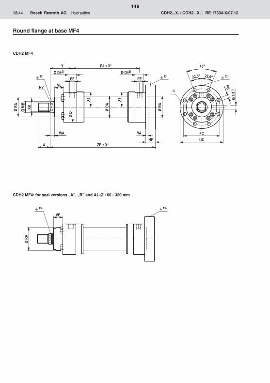
��
�
��
��� ���
��
��
�
�� ��
�
��
��
� %������
��������
����
��
����
��
�
���� ��
��
�'
�
��
��
&�
�
����
��
�'
(
��)( ��)(
��
������ ���
148
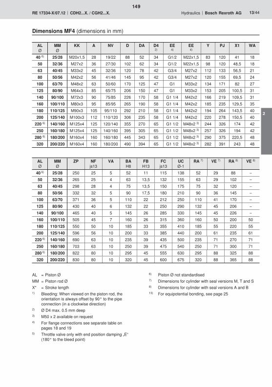
149
2
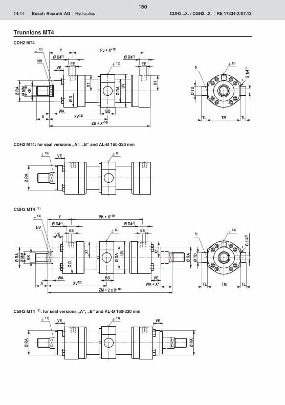
���
��
�
�� ��
�
��
���
�����������
����
����
����
��
����
��
�
��
�� ��
&�$� $�
+
�$�
$������
%'��������
'�
���
���
���
��
�
��
�
�� ��������
���
��
�
�� ��
�
��
���
�����������
����
����
����
��
����
��
�
��
�� ��&�
$� $�
+
�$�
$������
%������*������
'��������
��
��
�
���
���
���
��
�
��������
150
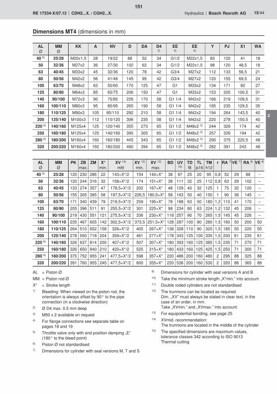
151
2
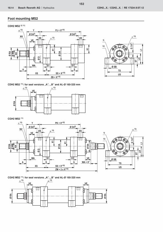
��
�
��������
���
��
�
�� ��
�
��
��
�
�����������
����
����
����
��
����
��
�
��
�� ��
&#
�#'
�,��
$#
#$
�#
%'��������##��������
#�
# #
#�
���
���
���
���
���
��
�
�� ��
�
��
��
�
�����������
����
����
����
��
����
��
�
��
�� ��
�������
��
��
�
&#
�#'
�,��
$#
#$
�#%������*������##��������
#�
# #
#�
���
���
���
���
��
�
��
�
�� ��������
152
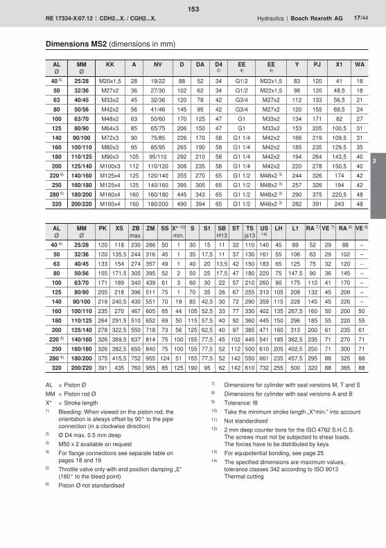
153
2
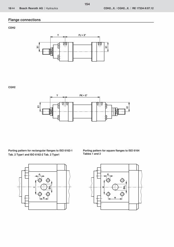
�������
��
���
�� ��
� �������
-
. / �
/�
-
- / �
/�
154
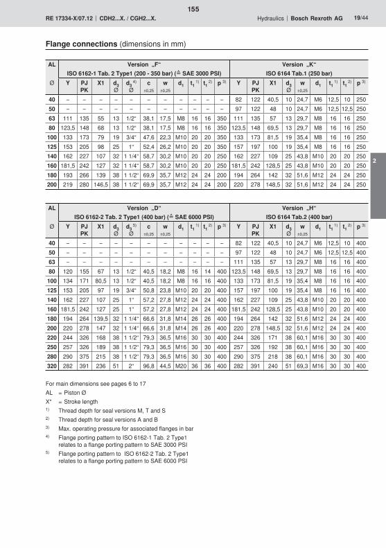
155
2
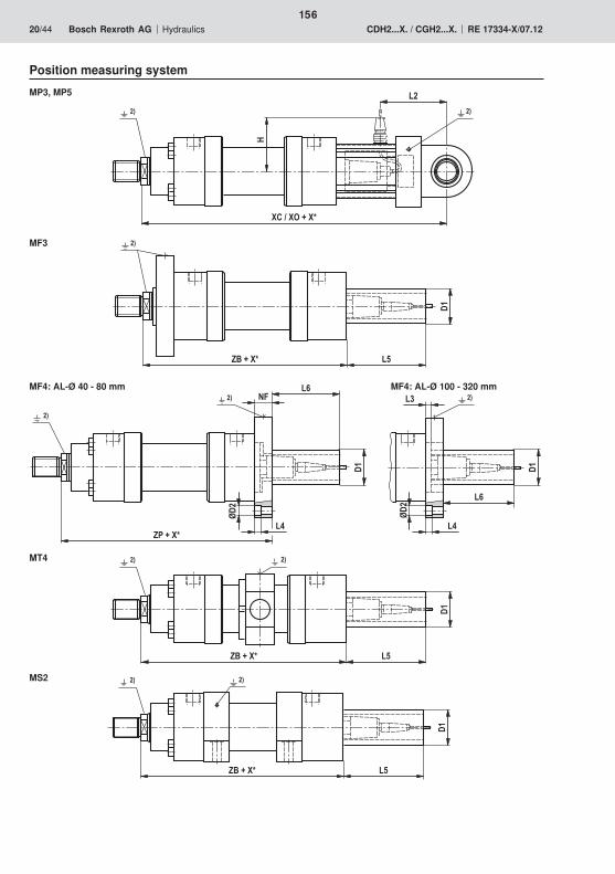
�%'�����
��
�� ��
�%������
���0
��
�0
�
�� ��
�� ����
��
�%'�����
��
����
�%'�����
��
����
������"�����
��
,
����
156
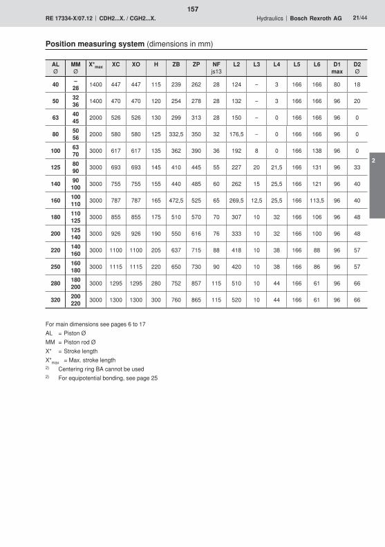
157
2
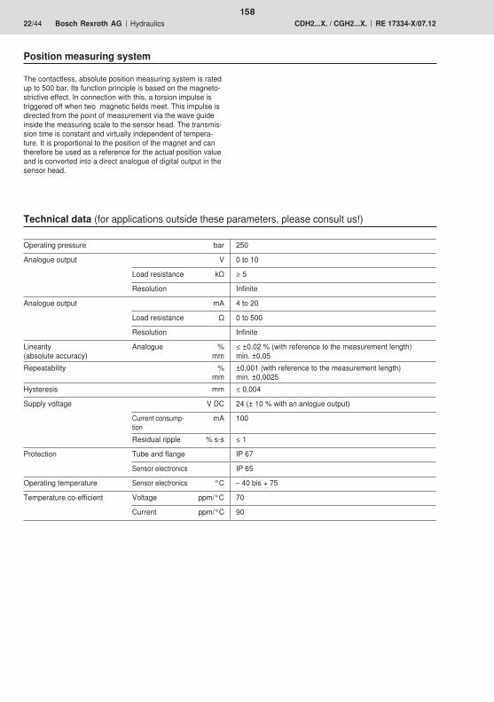
158
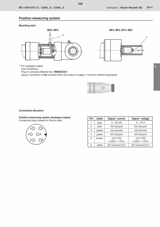
� �
� 0
����
159
2

� �
�
1
��
����
0
2���3
� �
�
1
��
0
2
3
��
��
��
�
160
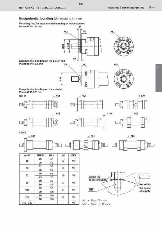
���������
���������
��� ��� ���
�����
��
�
���
���
�����
��
��
�
���
���
��
��
161
2
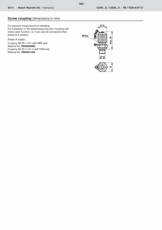
���
45*
6��1
���
��0*�
�1
162
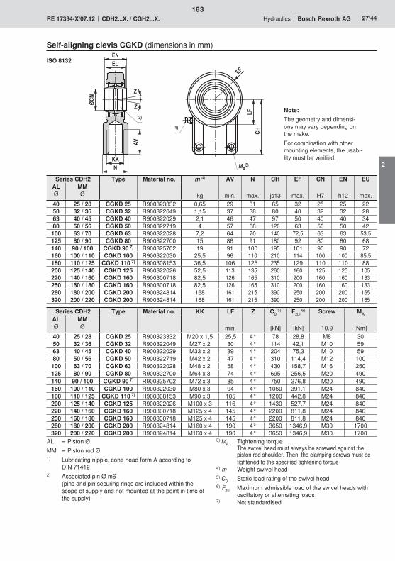
���&
�,��
��
����
��
�
% ��
%
��
��
��
163
2
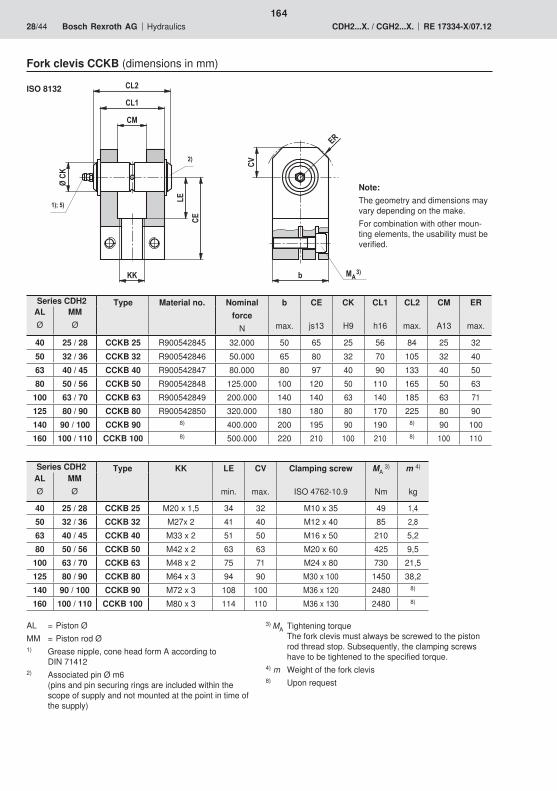
��7��
���
���
��
��
��
��
��
�
����8
��
��
��
164

��
�#�,
�
�
9�
��
��
�"
$,
&�
����
9���
165
2
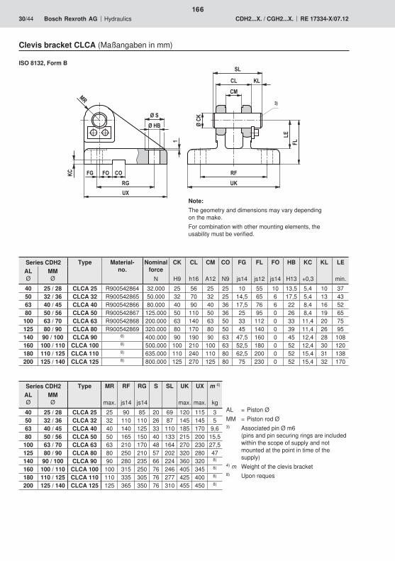
��
�#
�,'
�"�"����
��
&�
��
�
��
�
#�
�� ��
��
��
&�
��
��
166
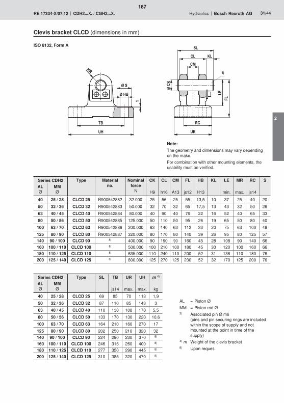
��
#�
�� ��
��
&�
��
��
�
��
��
&,
$'
�#
�,'
��
�
167
2

��
��
��
�
�
�
�
�
�
�
�
168
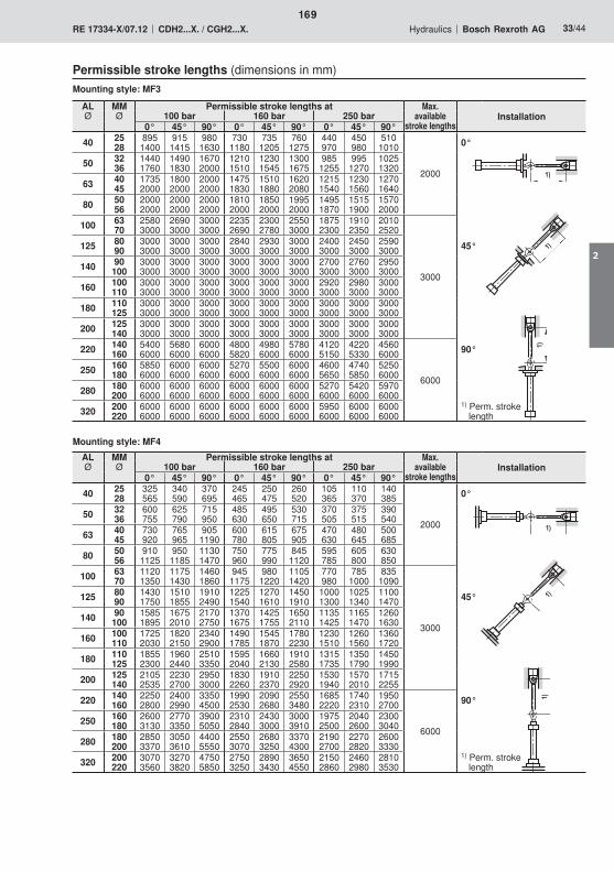
��
��
����
��
��
169
2
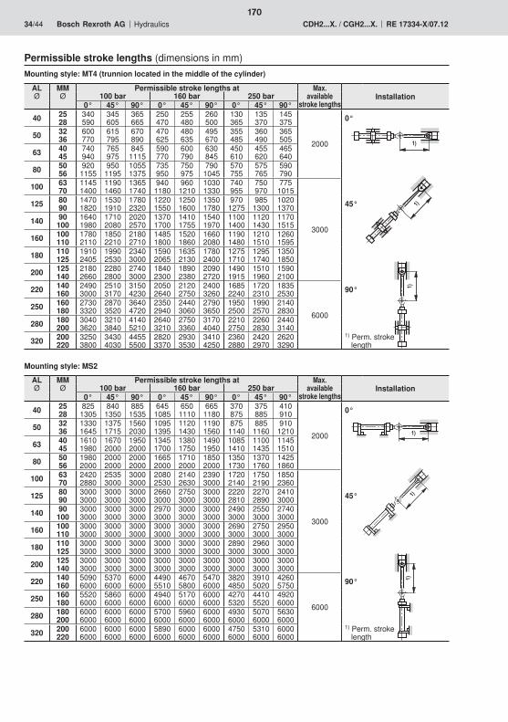
��
��
��
��
��
��
170
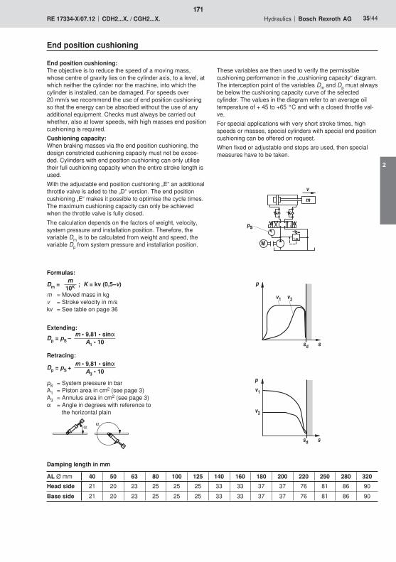
�
�
�:
�
�� ��
�
��/
��
��
�
��/
4
4
� �
171
2
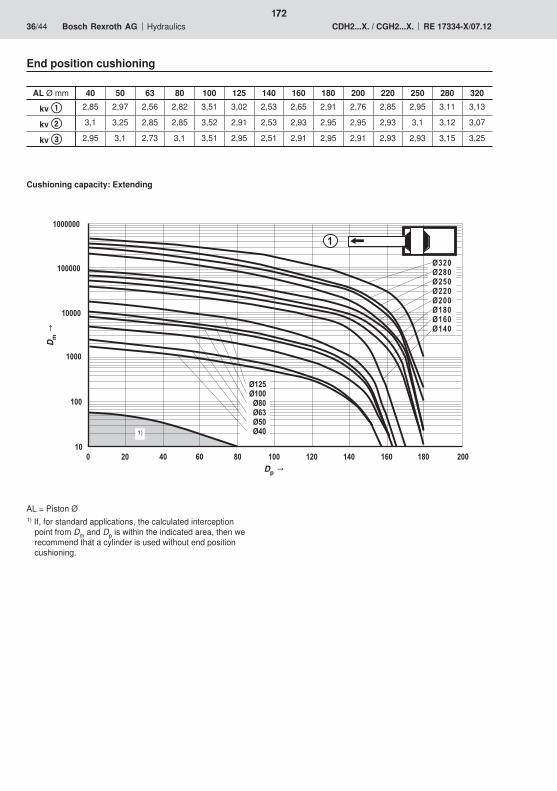
�������
������
�����
����
���
��� �� � 0� 3� ��� ��� �� �0� �3� ���
��� �3� �� ��� ��� �3� �0� ��
�� ��� 3� 0� � �
�
172

��������
�������
������
�����
����
���
��� 3� ��� �0� ��� ���� 0� ��� �� �3� ���
� ������� �3���3� ����0� ������
������ �3����� �0����� ���1�
���3� ����0� 3��� 0��� ���� ���
��������
�������
������
�����
����
���
��� 3� ��� �0� ��� ���� 0� ��� �� �3� ���
�
���1� ����2� 3��0 0�� ���0 ���3
������� �3����� ����3� �����0�
������ �3���� �0����� ������
173
2
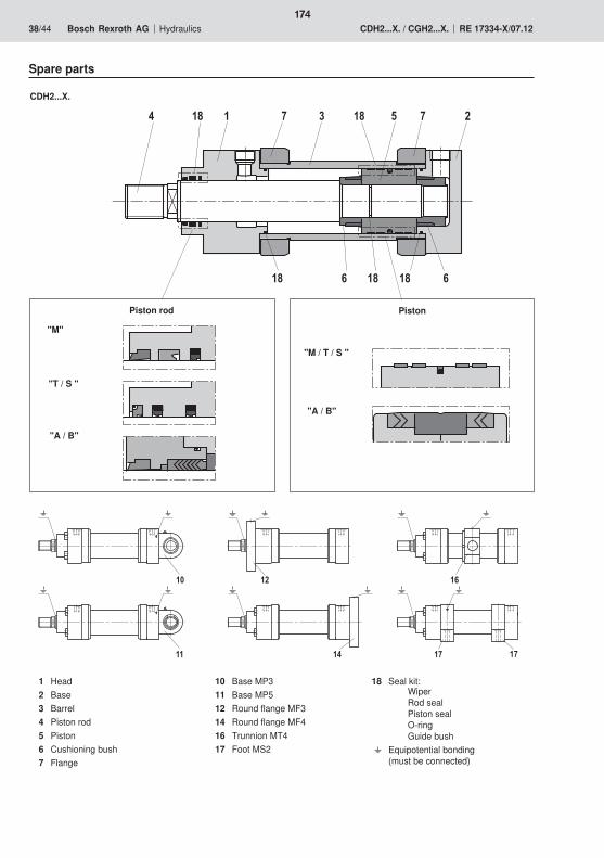
��3 2 � �3 2 �
0�3�30�3
��
�� ��
�
�0
�2�2
174
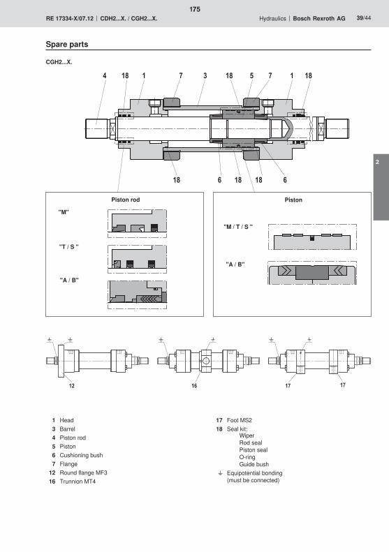
��3 2 � �3 2
0�3�30�3
�3�
�� �0 �2�2
175
2
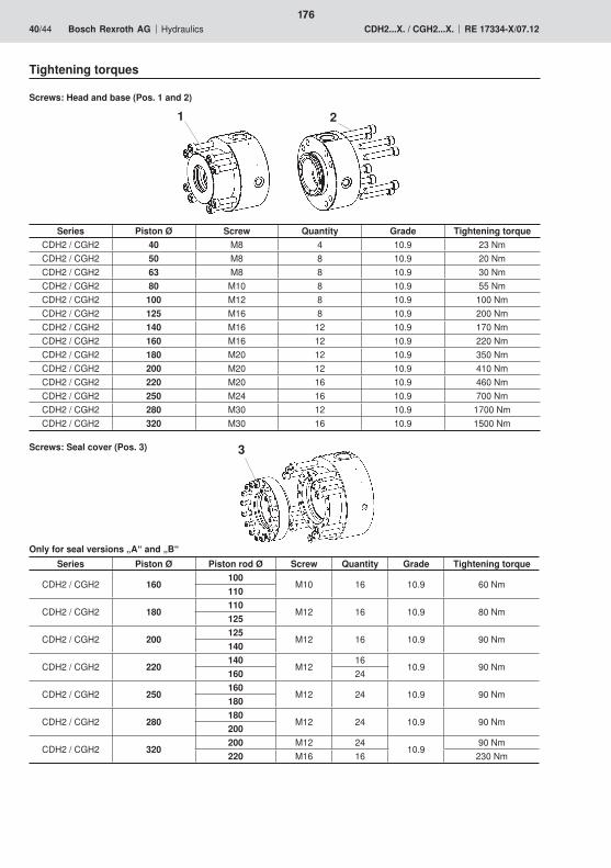
176
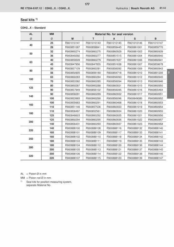
177
2
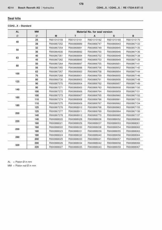
178
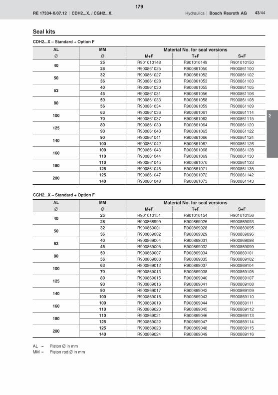
179
2
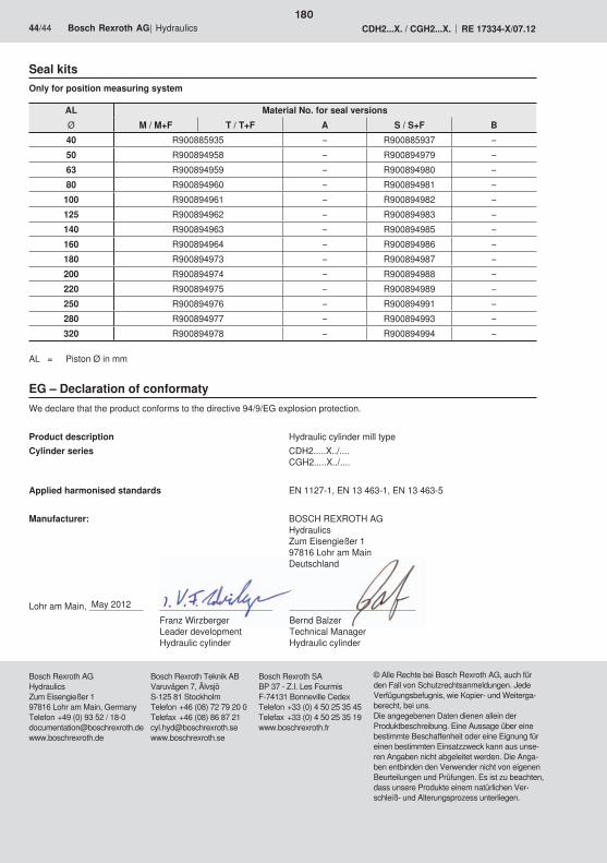
180

RE 00112-10, Edition: 2013-12, Bosch Rexroth AG
Designation Type SizeComponent
seriespmax
in bar Data sheet Page
On/off valves
Contents | On/off valves | Explosion protection
Directional seat valves, direct operated3/2 and 4/2 directional seat valves with solenoid actuation M-.SE...XD 6 6X 420 22047-XD-B2 1833/2 and 4/2 directional seat valves with solenoid actuation E(W)-.SE...XH 6 6X 420 22047-XH-B2 1973/2 and 4/2 directional seat valves with solenoid actuation M-.SED...XE 6 1X 350 22049-XE-B2 2133/2 and 4/2 directional seat valves with solenoid actuation M-.SED...XN 6 1X 350 22049-XN-B2 2292/2, 3/2 and 4/2 directional seat valves with solenoid actuation
M-.SEW...XE 6 3X 420 22058-XE-B2 245
3/2 and 4/2 directional seat valves with solenoid actuation M-.SEW...XE 10 1X 420 22075-XE-B2 2593/2 and 4/2 directional seat valves with solenoid actuation M-.SED...XN 10 1X 350 22045-XN-B2 273
Directional spool valves, direct operated4/3, 4/2 and 3/2 directional valves with wet-pin DC solenoids
WE...B...X 6 5X 210 23177-XH-B2 289
4/3, 4/2 and 3/2 directional valves with DC solenoids WE...E..XD 6 6X 315 23178-XD-B2 3014/3, 4/2 and 3/2 directional valves with wet-pin DC or AC solenoids
WE...E..XE 6 6X 350 23178-XE-B2 315
4/3, 4/2 and 3/2 directional valves with wet-pin DC solenoids
WE...E..XN 6 6X 350 23178-XN-B2 331
4/3, 4/2 and 3/2 directional valve with manual actuation WMM ...XC 6 5X 315 22280-XC-B2 3434/3, 4/2 and 3/2 directional valve with fl uidic actuation WP ...XC,
WH ...XC6 6X, 5X 315 22282-XC-B2 353
Directional spool valves, pilot operated4/2 and 4/3 directional valves, internally pilot opera-ted, externally pilot operated
H-4WEH...XD 10...32 4X, 6X, 7X 350 24751-XD-B2 365
4/2 and 4/3 directional valves, internally pilot opera-ted, externally pilot operated
H-4WEH...XE 10...32 4X, 6X, 7X 350 24751-XE-B2 389
Pressure valvesPressure reducing valve, direct operated DR.DP...XC,
ZDR.D...XC6 5X, 4X 315 26564-XC-B2 413
Pressure relief valve, pilot operated DB...5X/...XC 10...30 5X 350 25802-XC-B2 425Safety valves, directly operated DBDH...1X/...XC...E 4...30 1X 630 25010-XC-B2 437
Flow control valvesTwin throttle-type check valve, direct operated Z2FS...XC 6 4X 315 27506-XC-B2 453
1
2
3
4
5
6
181
3

Bosch Rexroth AG, RE 00112-10, Edition: 2013-12
182

183
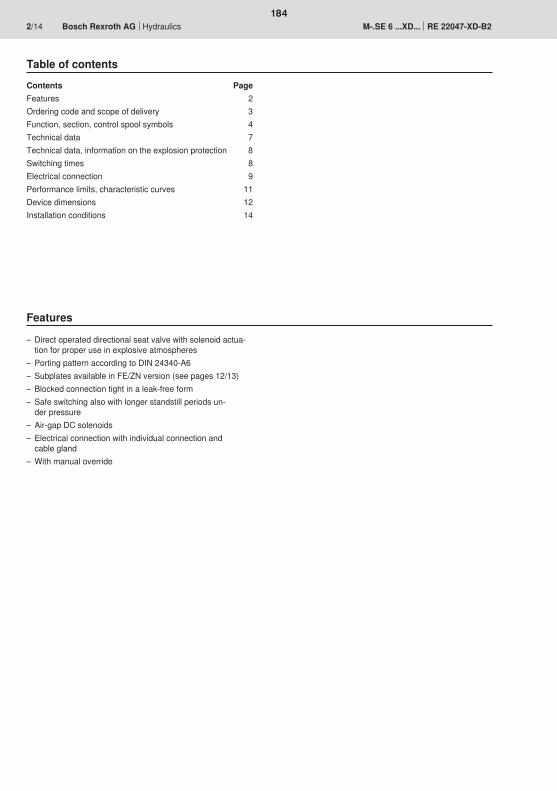
184
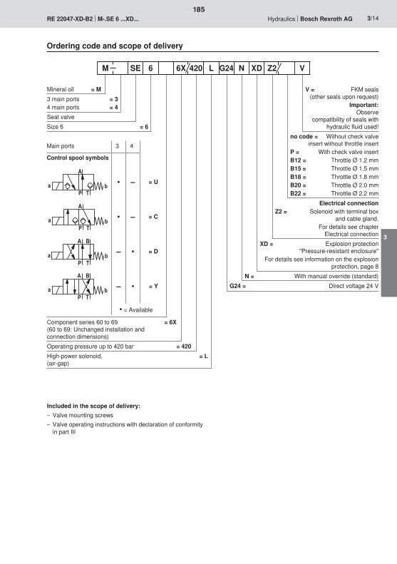
�
$�5 8
�
$�5 8
5 8
�
� $
'
'�
$�5 8
185
3
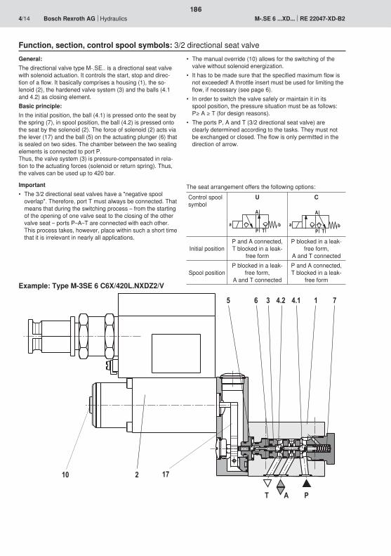
$ ��
�
2�6��0 6�
�� �2
�
$�5 8
�
$�5 8
186
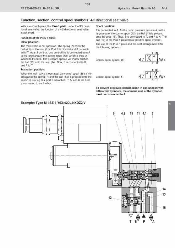
$ ' � �
2�� 6�
�0
�
����
�3 6�
5 8
�
� $
'
'�
$�5 8
187
3
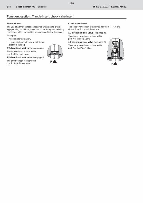
��
188
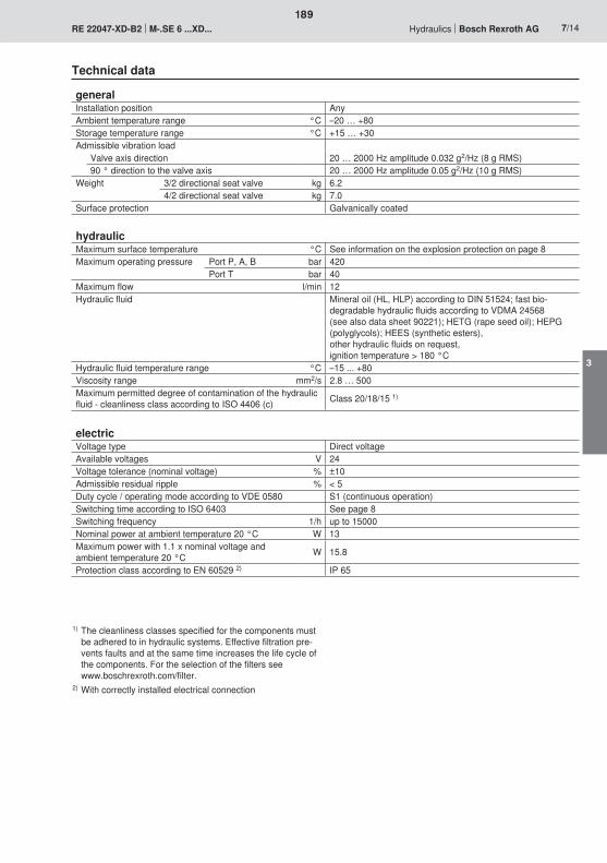
189
3
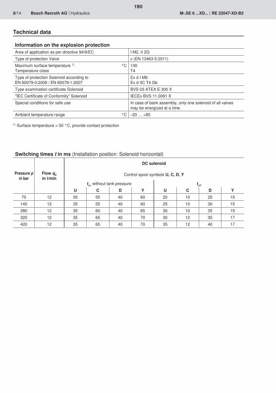
190
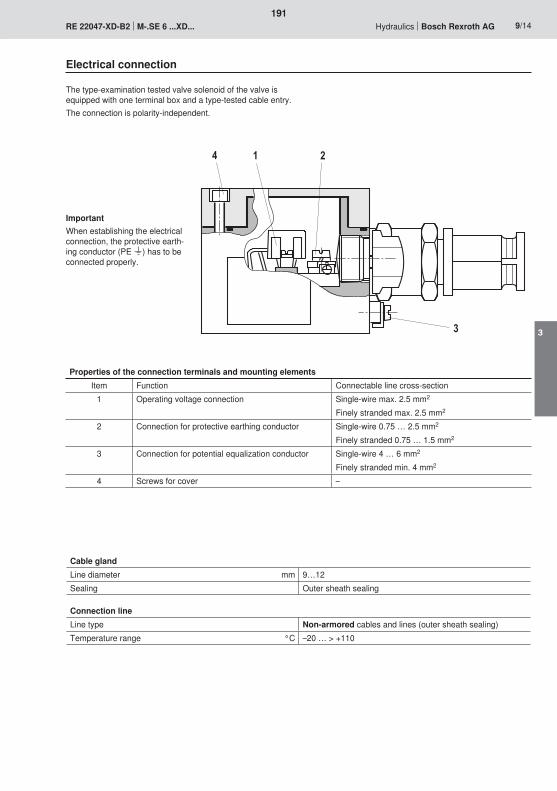
�
�
�
191
3
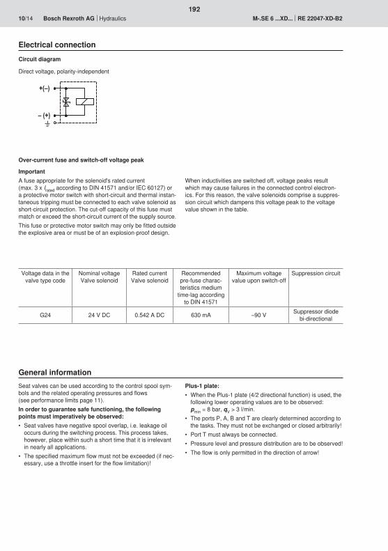
�;<�
<�;��
192
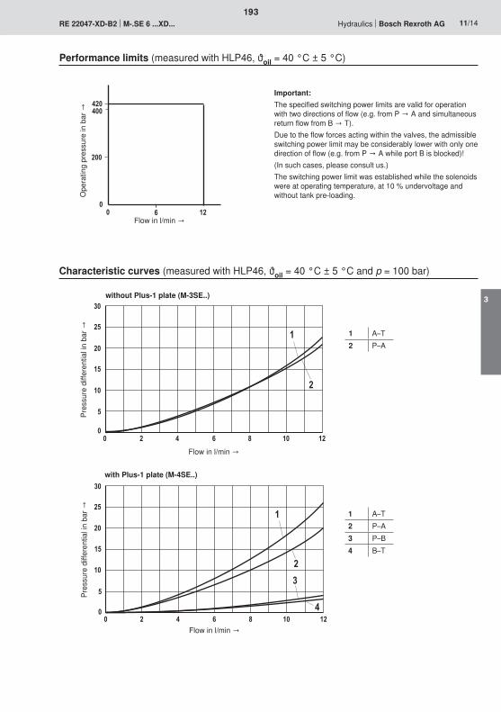
����
���
�� 0 ��
� ����30�
��
�
��
�
�
��
�
�
� ����30�
��
�
��
�
�
��
�
�
�
193
3
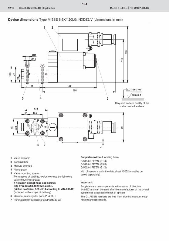
�10
�1
��3
3�
��
�
��
3
��
)
)�
��
�
�
3) �)
0�)
��) ��
20
�' �
$
Rzmax 4
0,01/100
194
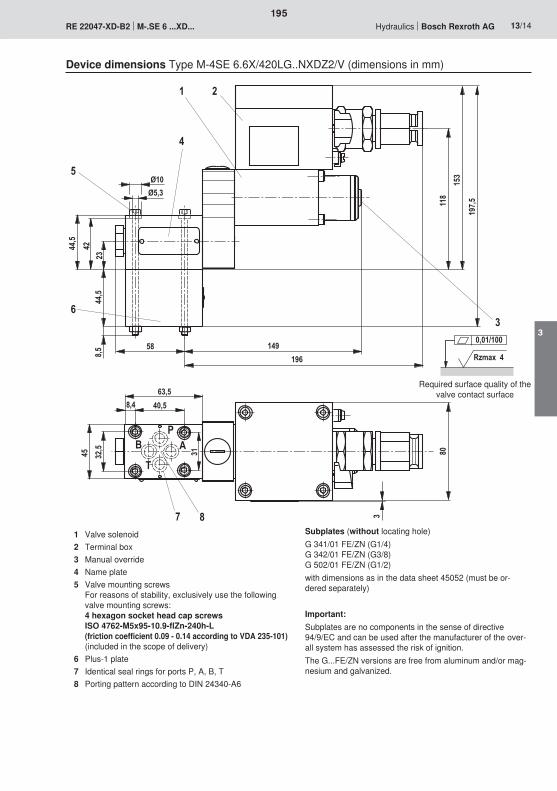
3
�10
�1
��3
3�
��
)
��
)�
��
�3)
)
2
�
0
3
�
�
�12)
�
3) �)
0�)
��) ��
�' �
$
Rzmax 4
0,01/100
195
3
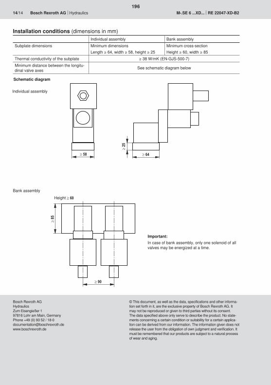
196

197
198
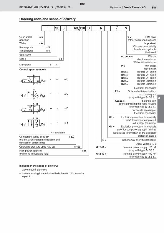
�
$�5 8
�
$�5 8
5 8
�
� $
'
'�
$�5 8
199
3
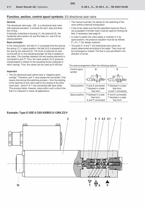
� 2�6��0
��$
6�
��
�
$�5 8
�
$�5 8
200
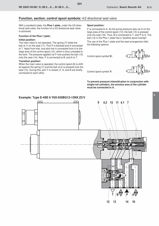
$ ' � �
�0�����
6� 2���3 6�
5 8
�
� $
'
'�
$�5 8
201
3
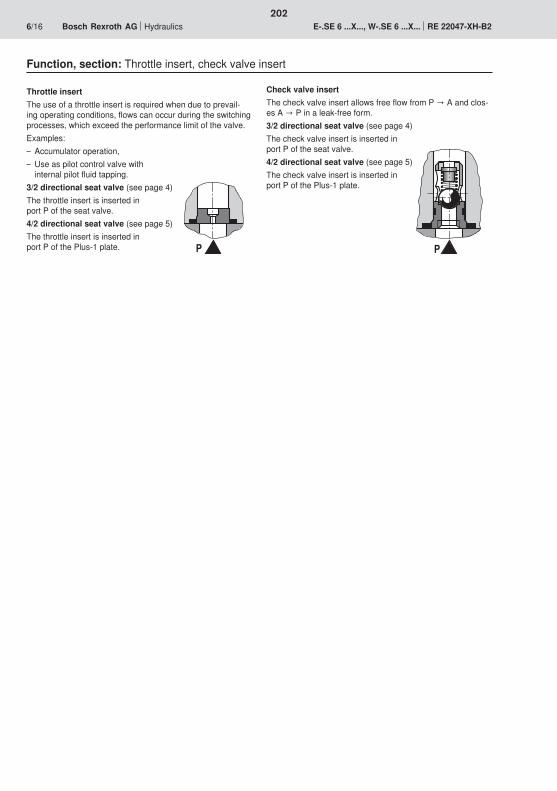
� �
202
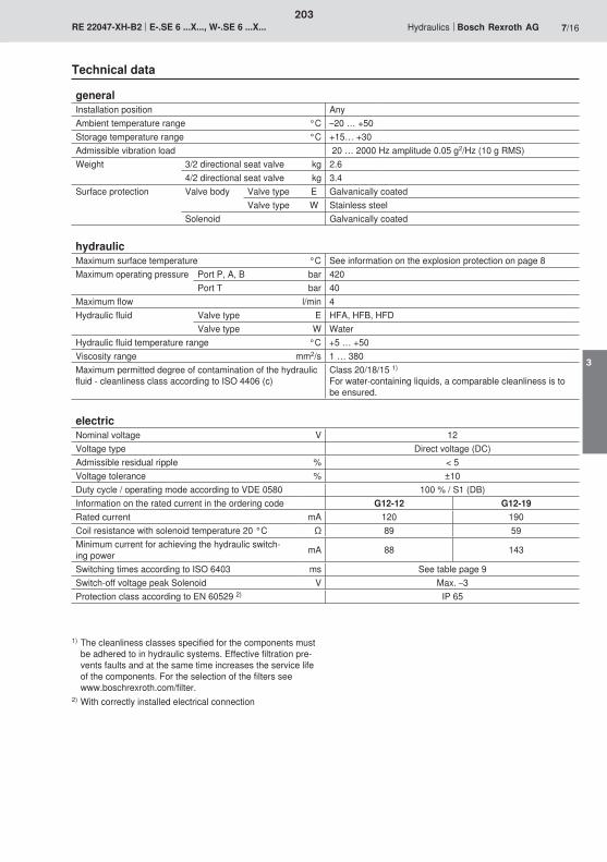
203
3
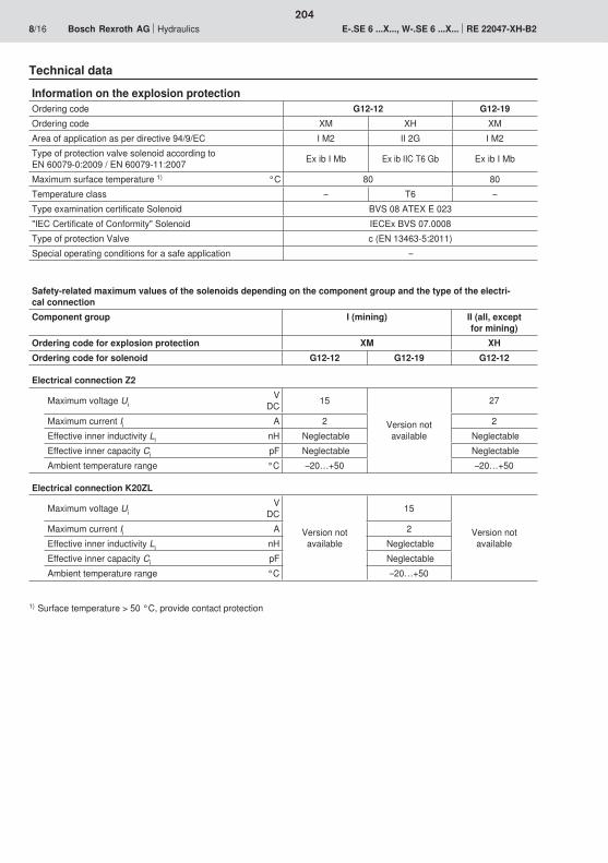
204
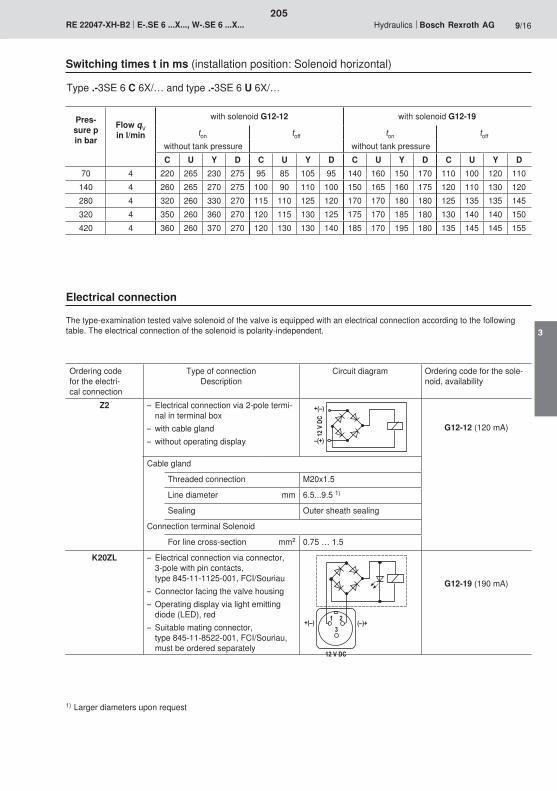
������
�
�;<�
<;��
� �
��;<� ;<��
�������
205
3
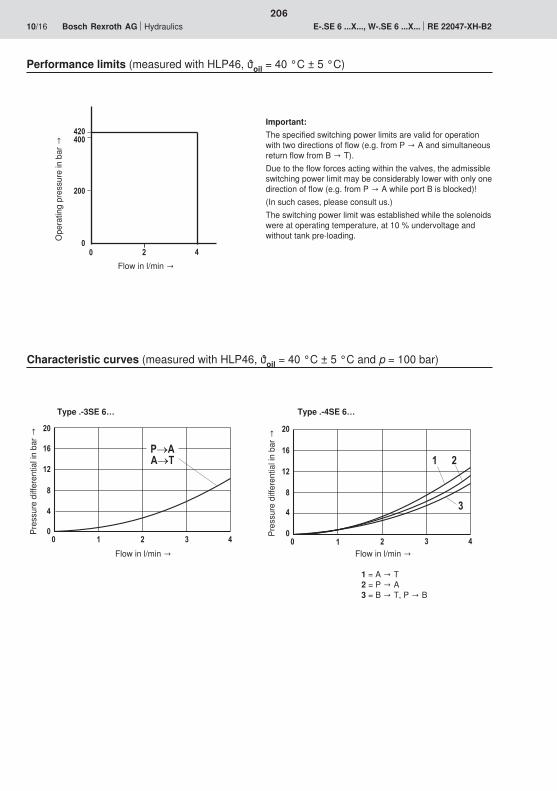
����
���
�� �
��
�����
3
��
�0
�
�
�
��
�
3
��
�0
����
�����$
206
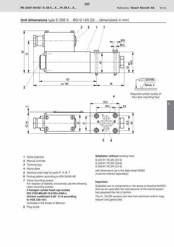
��2
3)�)
0�)
)�
��
3.56���
2�
��
��)
�
1
)�
�
0
� ��
�
$
'
�
�
�
23
Rzmax 4
0,01/100
207
3
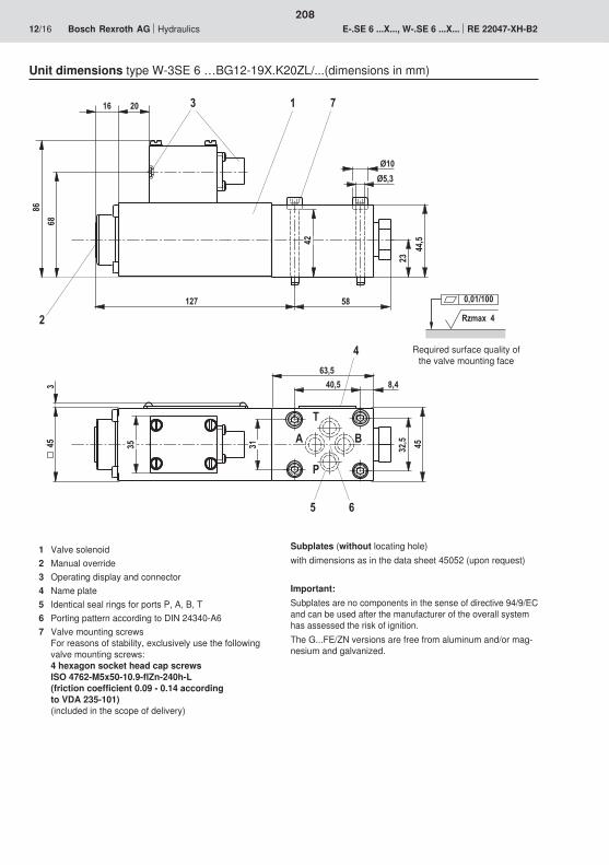
��2
3)�)
0�)
)�
��
3
03
����
)� ��
�
30
)�
���0
0
��
�
'�
�
$
2
Rzmax 4
0,01/100
208
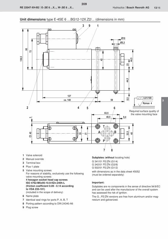
3)
��2
3)�)
0�)
)�
��
3.56���
2�
��
��)
�
1
)
)
�
�
32
0
� ��
�
$
'
�
�
�
��1)
1
Rzmax 4
0,01/100
209
3
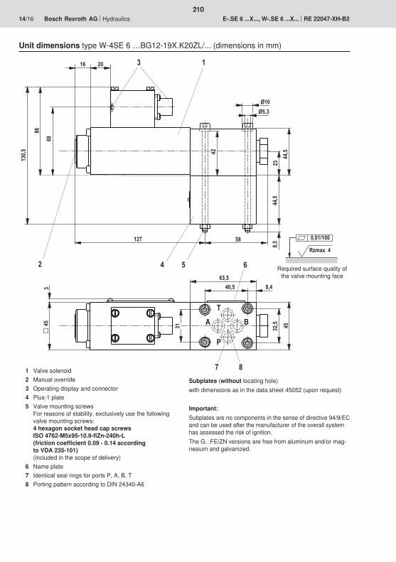
3)��2
3)�)
0�)
)�
��
3
03
����
)��
�
30
)
)
�
���0
2 3
0
��
�
'�
�
$
���)
Rzmax 4
0,01/100
210
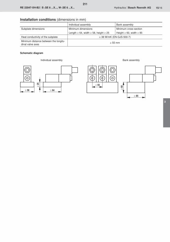
211
3

212
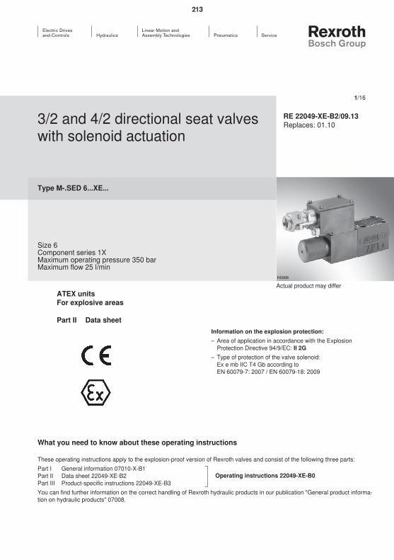
213
214
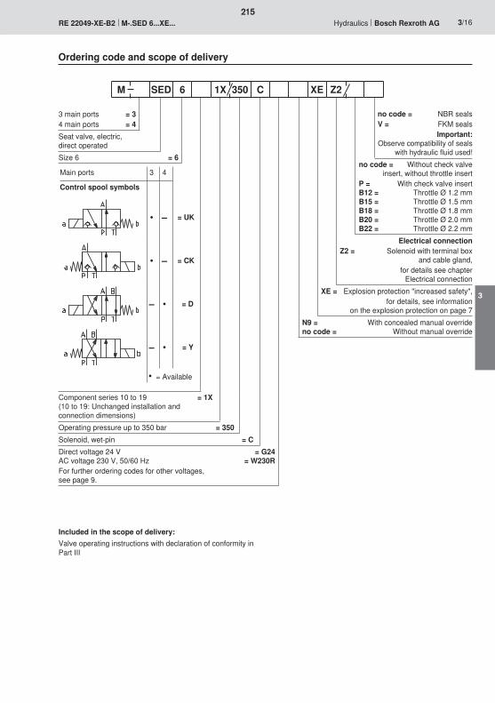
215
3
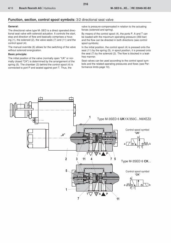
T A P
T A P
1
5741132
5
1
7 11
„a“
216
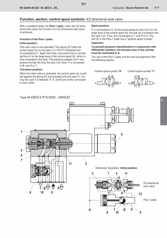
T B P A8 10 9
745
1
11 2
6
� $ ' �
$ �
� 2 ��
��
1��3
217
3
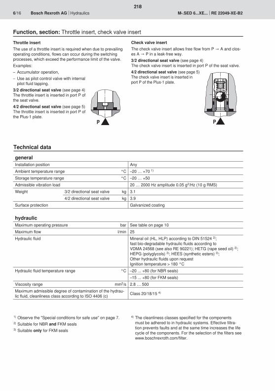
� �
218
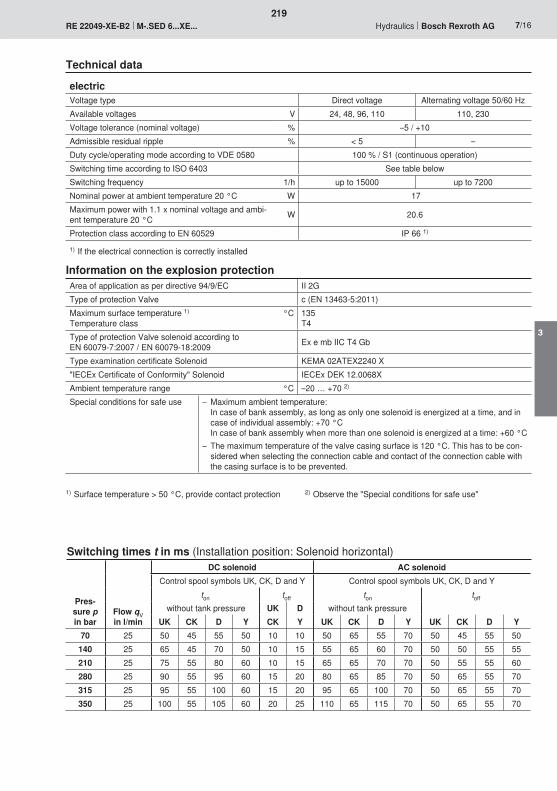
219
3
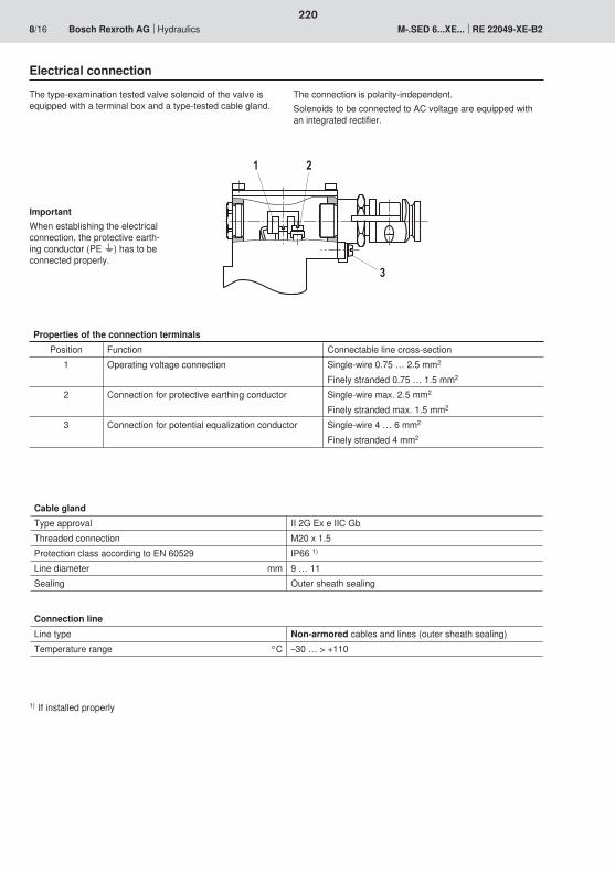
2
3
1
220
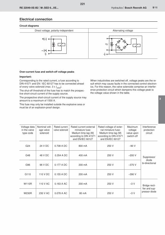
�;<�
<�;��
221
3
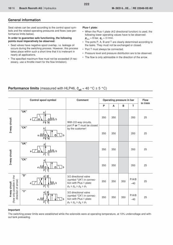
222
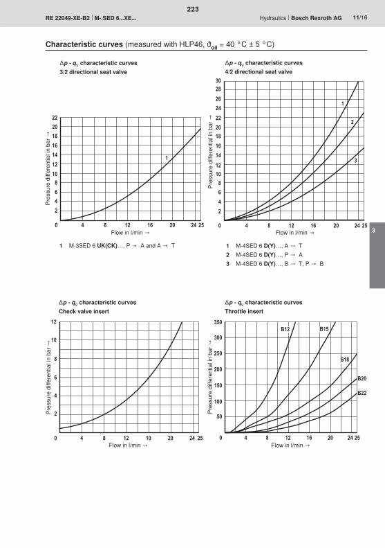
��
��
�3
�0
�
��
��3
0
�
� 3 �� �0 �� � �
�
���3
�0
�
��
���3
�0
�
����
3
0
�
� 3 �� �0 �� � �
�
�
�
��
��
3
0
�
� 3 �� �� �� � �
��
���
���
��
��
���
�
� 3 �� �0 �� � �
'��
'��
'�3
'�'��
223
3
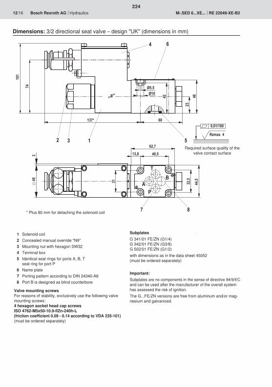
A
T
P
B
32,5
44,5
40,513,8
62,7
3160
Ø10Ø5,5
3
2346
5
87
2
42„a“
3
1
4 6
137*
45
101
74
Rzmax 4
0,01/100
224
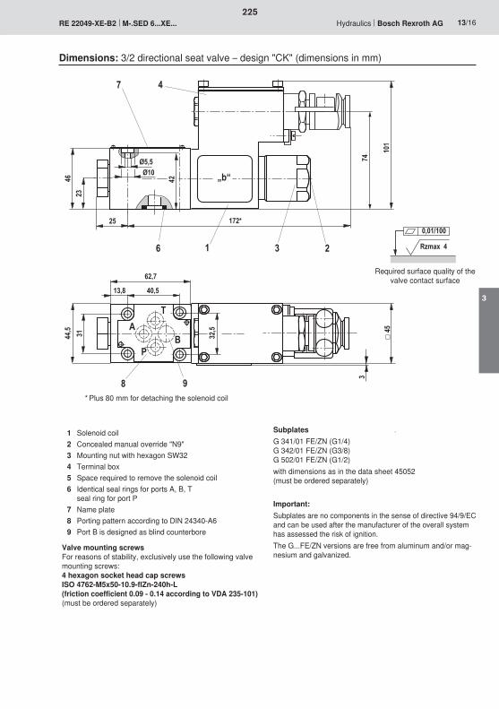
32,5
44,5 31 45A
PB
T
13,8 40,5
62,7
25
Ø10Ø5,5
2346
101
74
1
98
2
42
6
3
„b“
3
47
172*
Rzmax 4
0,01/100
225
3
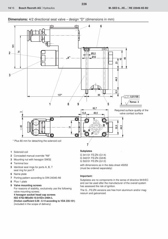
Rzmax 4
0,01/10060
8,544
,523
42 46
Ø5,5Ø10
981
4
5
„a“2
6
3
7
32,5
44,5
13,8 40,5
62,7
AP
BT
3
137*
31 45
101
74
226
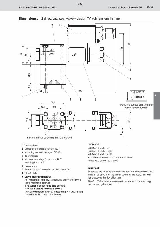
25
8,544
,5
46 4223
Ø10Ø5,5
59 8 1
4
101
6
2
3
172*
62,7
7
P
AT
B3144,5
13,8 40,5
32,5
3
„b“
45
74
Rzmax 4
0,01/100
227
3
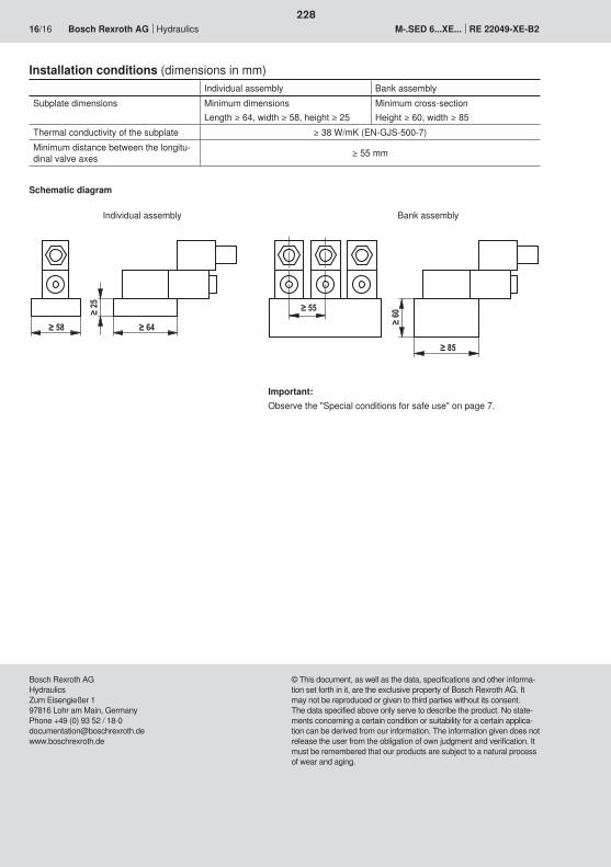
228
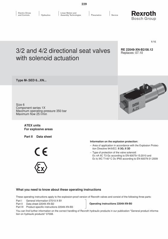
229

230
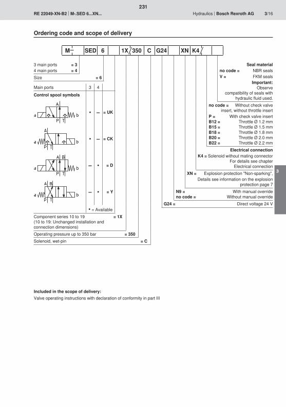
231
3
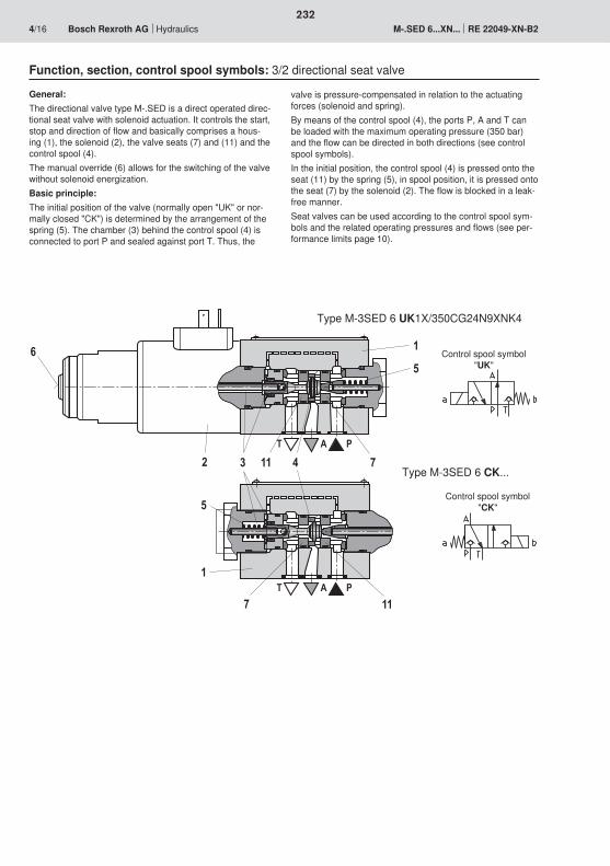
T A P
T A P
5
1
7 11
74113
1
5
2
6
232
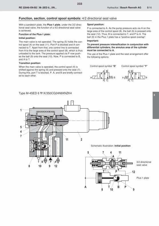
� $ ' �
$ �
� 2 ��
��
1��3
T B P A8 10 9
745
1
11 2
12
233
3
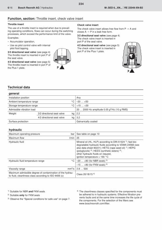
�
234
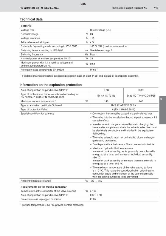
235
3
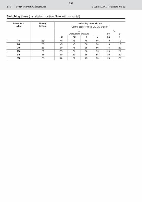
236
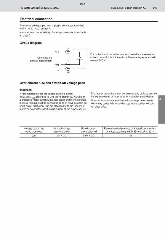
�;<�
<�;��
�
�
237
3
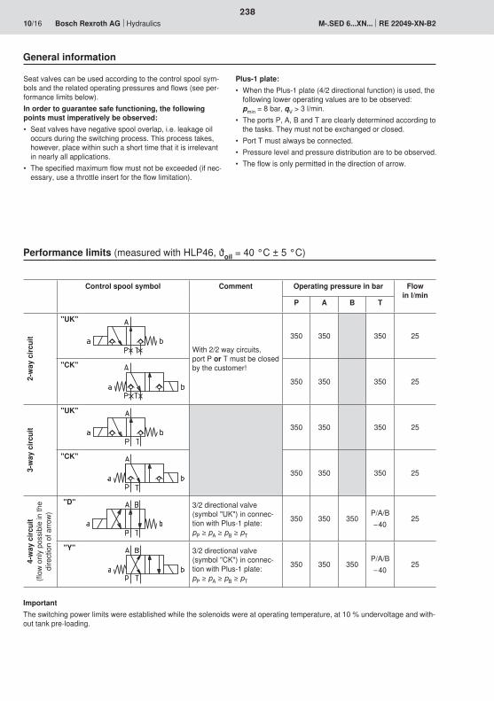
238
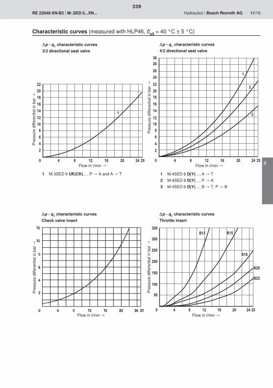
��
��
�3
�0
�
��
��3
0
�
� 3 �� �0 �� � �
�
���3
�0
�
��
���3
�0
�
����
3
0
�
� 3 �� �0 �� � �
�
�
�
��
���
���
��
��
���
�
� 3 �� �0 �� � �
'��
'��
'�3
'�'��
239
3
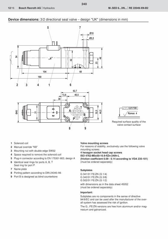
Rzmax 4
0,01/100
104
32,5
2344
,5
40,513,862,7
6042
Ø5,5
Ø10
P
AT
B
6
8
75
2 1
9
31Ø45
„a“
3
160
4
46 54
34
240
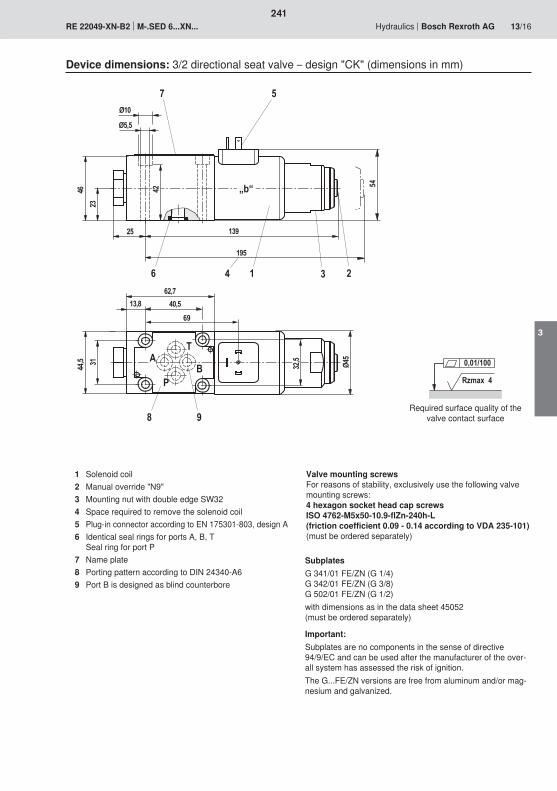
139
31 Ø45
4623
44,5
40,513,862,7
25
Ø5,5
Ø10
P
AT
B
6
8
7 5
21
9
3
195
4
32,5
42 54„b“
69
Rzmax 4
0,01/100
241
3
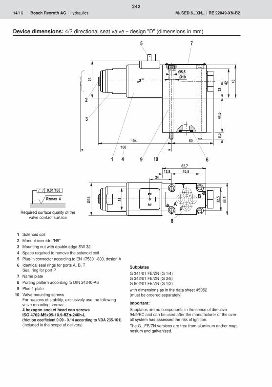
60
8,544
,523
42
Ø5,5Ø10
1091
5
6
54 „a“
2
7
104
3
832
,544
,5
13,8 40,562,7
AP
B
T
Ø45
31
160
4
46
34
Rzmax 4
0,01/100
242
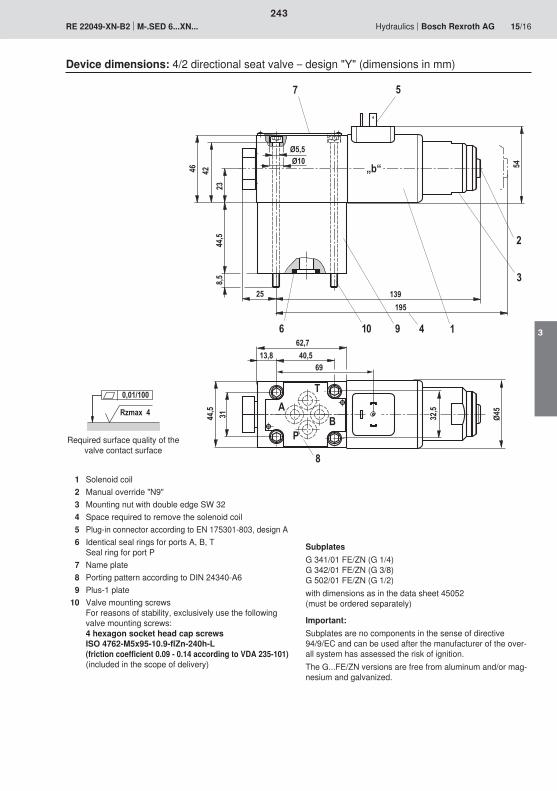
25
8,544
,542
23
Ø10Ø5,5
6 10 9 1
5
54
7
2
3139
62,7
8
P
AT
B3144,5
13,8 40,569
Ø45
„b“
32,5
195
4
46
Rzmax 4
0,01/100
243
3
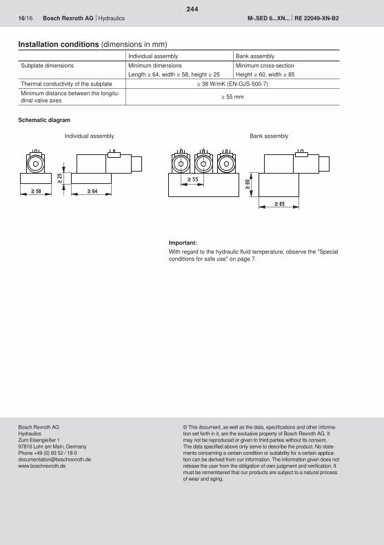
55
244
245
246
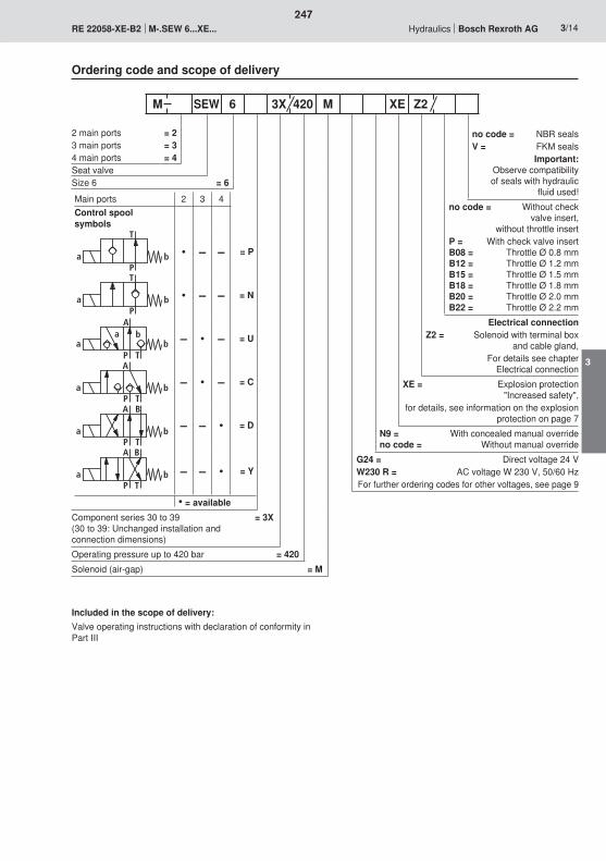
A
TP
a ba b
A
TPa b
BA
TPa b
BA
TPa b
247
3

10
2
6
7
3
9
1T
AP
8
6
79
1
T P
48
A
TP
a ba b
A
TPa b
248
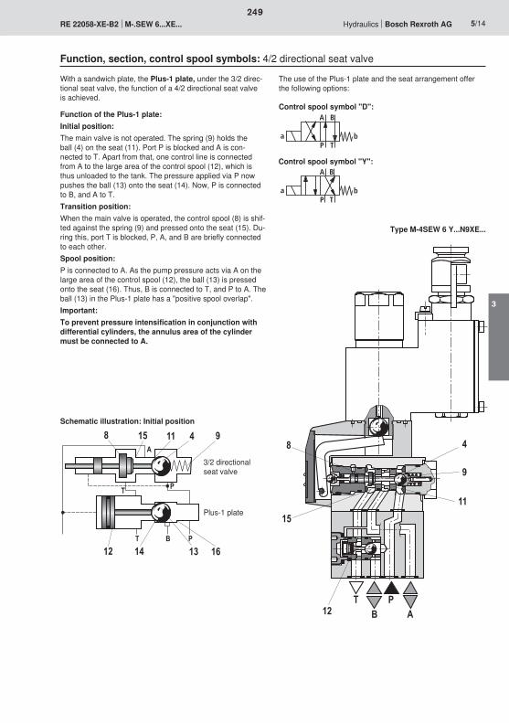
BA
TPa b
BA
TPa b
A
T B P
PT
8 15 11 4
12 14 13
9
16
8
15
4
9
11
TA
PB12
249
3
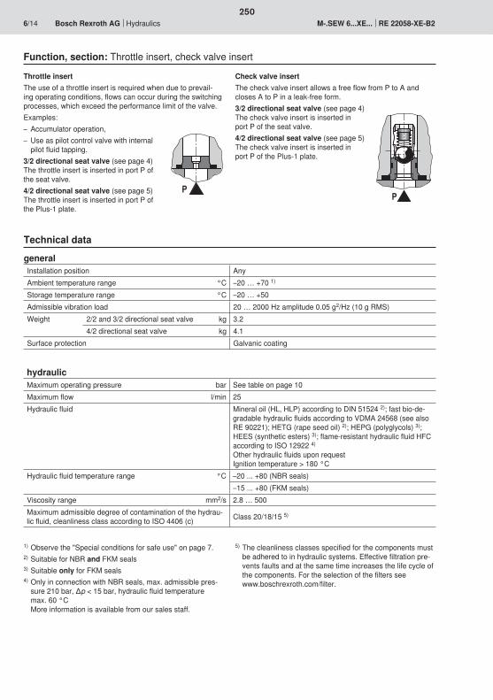
PP
250
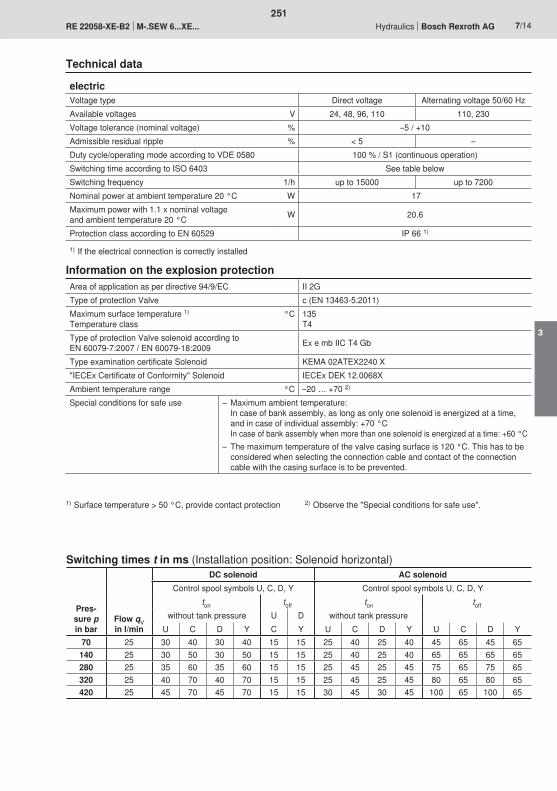
251
3
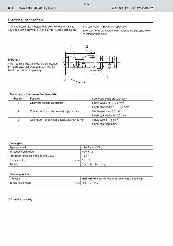
2
3
1
252

�;<�
<�;��
253
3
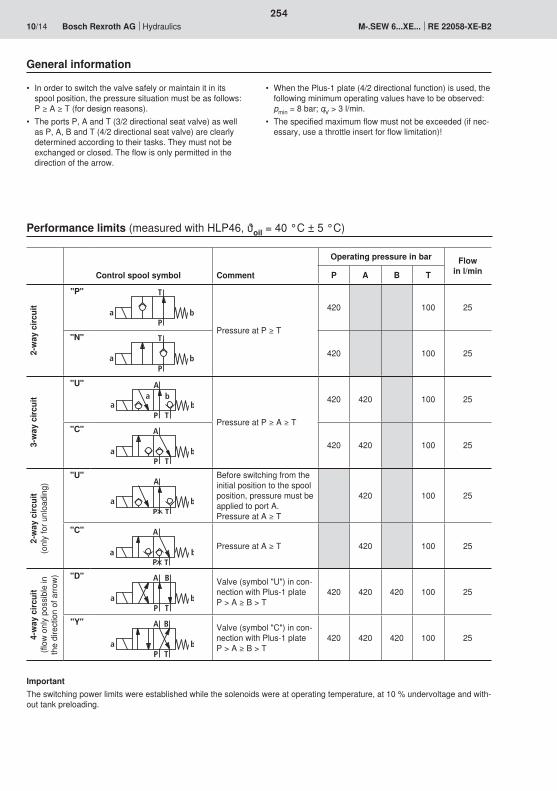
A
TP
a ba b
A
TPa b
A
TPa b
A
TPa b
BA
TPa b
BA
TPa b
254
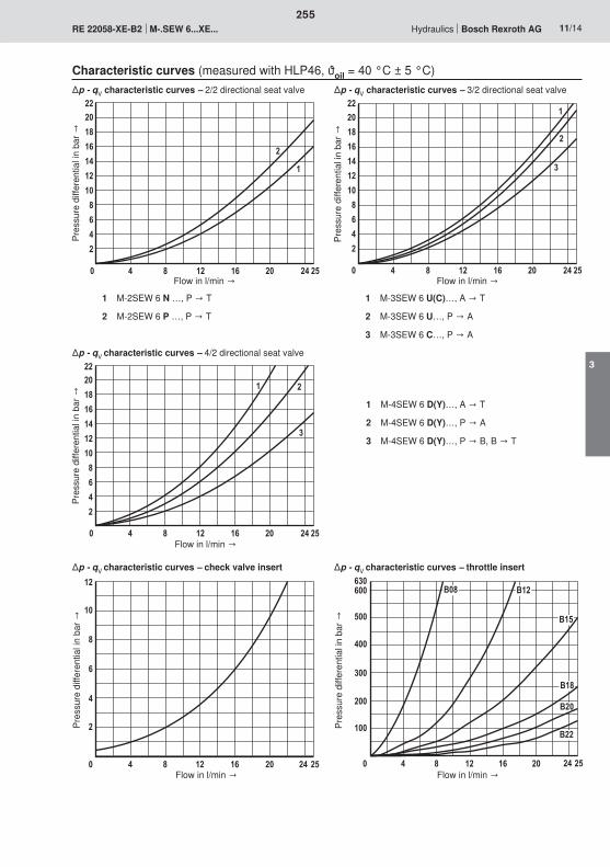
22201816141210
8642
0 4 8 12 16 20 24 25
2
1
222018161412108642
0 4 8 12 16 20 24 25
2
1
3
222018161412108642
0 4 8 12 16 20 24 25
21
3
12
10
8
6
4
2
0 4 8 12 16 20 24 25
630600
500
400
300
200
100
0 4 8 12 16 20 24 25
B12
B15
B18
B20
B22
B08
255
3
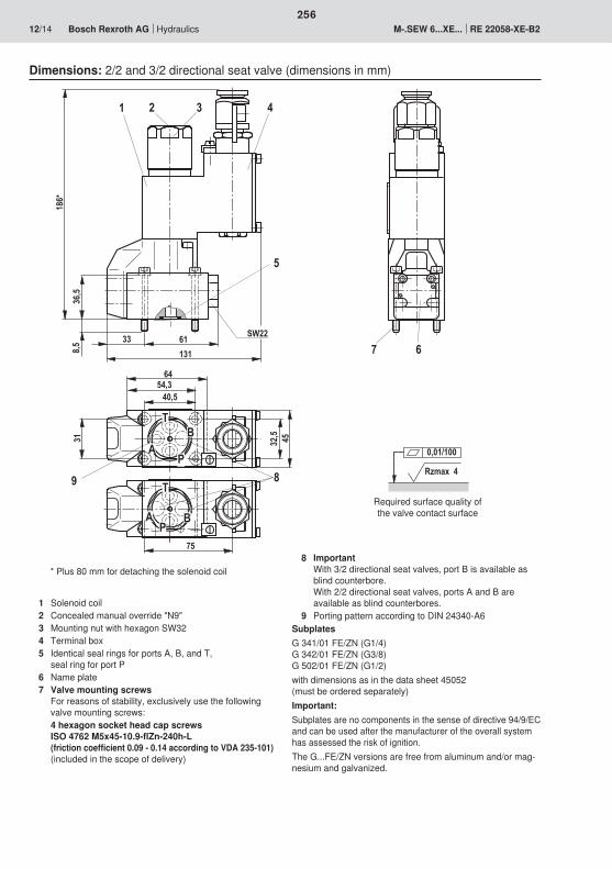
Rzmax 4
0,01/100
31
40,554,3
64
1316133 SW22
8,536
,5
186*
2 31 4
5
7 6
9 8
32,5 45
A
TB
P
T
BP
A
75
256
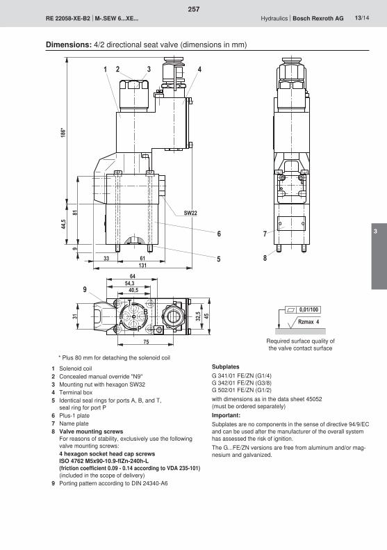
Rzmax 4
0,01/100
186*
44,5
819
13161
SW22
321 4
6
5 8
7
31
40,554,3
64
9
33
75
45
TB
PA 32
,5
257
3
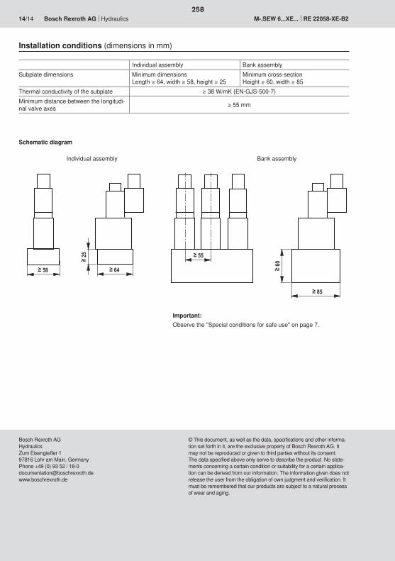
64
55
60
25
58
85
258

259
260
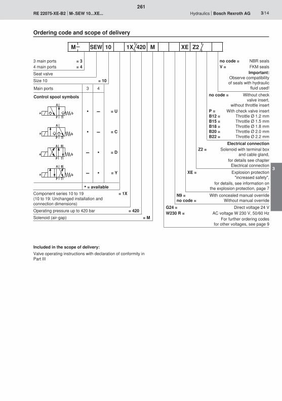
A
TPa b
A
TPa b
a b
A
P T
B
BA
TPa b
261
3
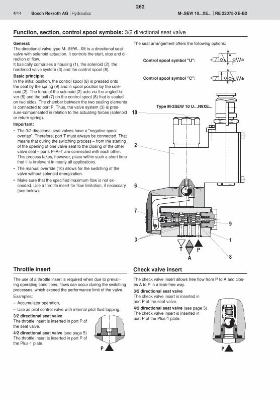
PP
A
TPa b
A
TPa b
10
2
6
7
3
9
1T
AP
8
262

A
T B P
PT
8 15 11 4
12 14 13
9
16
a b
A
P T
B
BA
TPb
8
15
4
9
11
TA
PB
263
3
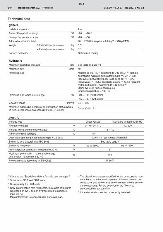
264
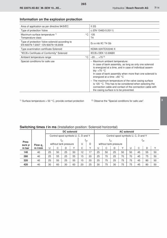
265
3
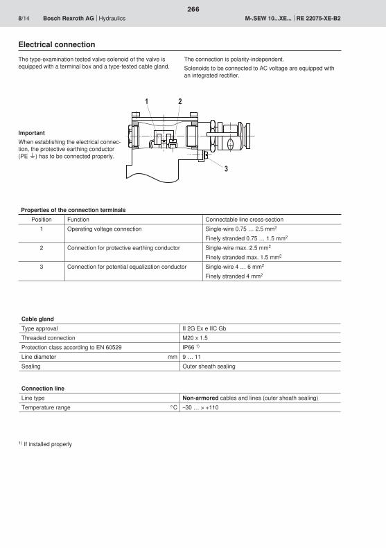
2
3
1
266

�;<�
<�;��
267
3

A
TPa b
A
TPa b
A
TPa b
A
TPa b
a b
A
P T
B
BA
TPa b
268
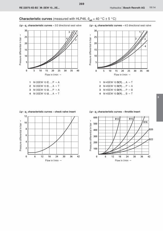
30
25
20
15
10
5
0 5 10 15 20 25 30 35 40
13
4 2
30
25
20
15
10
5
0 5 10 15 20 25 30 35 40
1
3
4
2
12
10
8
6
4
2
0 6 12 18 24 30 36 42
600
500
400
300
200
100
0 6 12 18 24 30 36 42
B12 B15B18
B20
B22
269
3
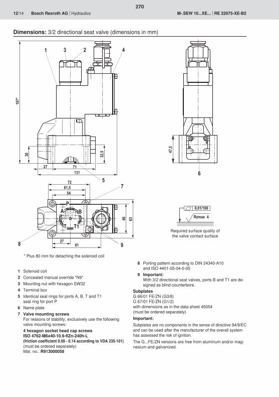
30
197*
27 71131
72
54
63
46
231 4
5
8 9
7
647
,5
61,5
P
2781
BA
T T1
32,5
Rzmax 4
0,01/100
270
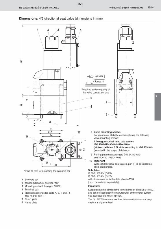
197
48
7812
98131
7261,5
54
46 63
231 4
6
5
109
8
7
PBA
T T1
2781
27
Rzmax 4
0,01/100
271
3
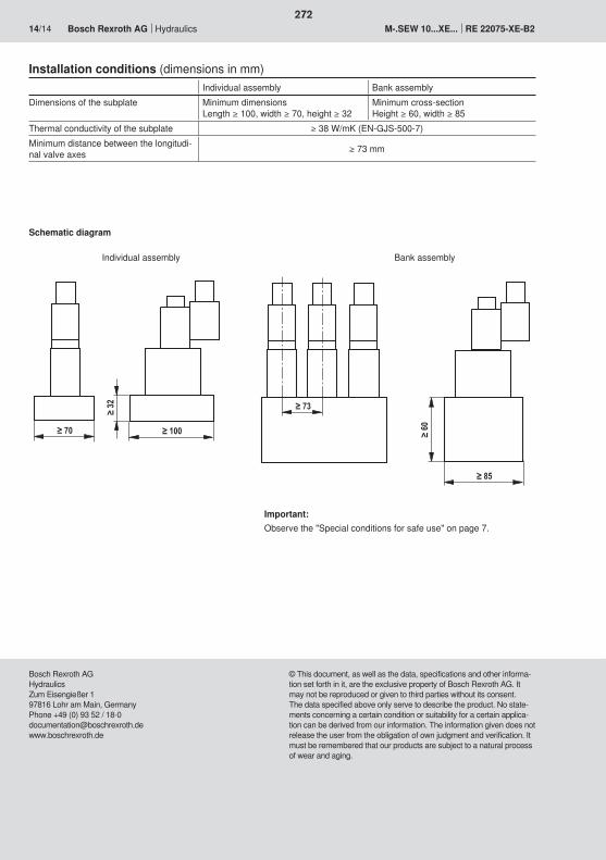
272
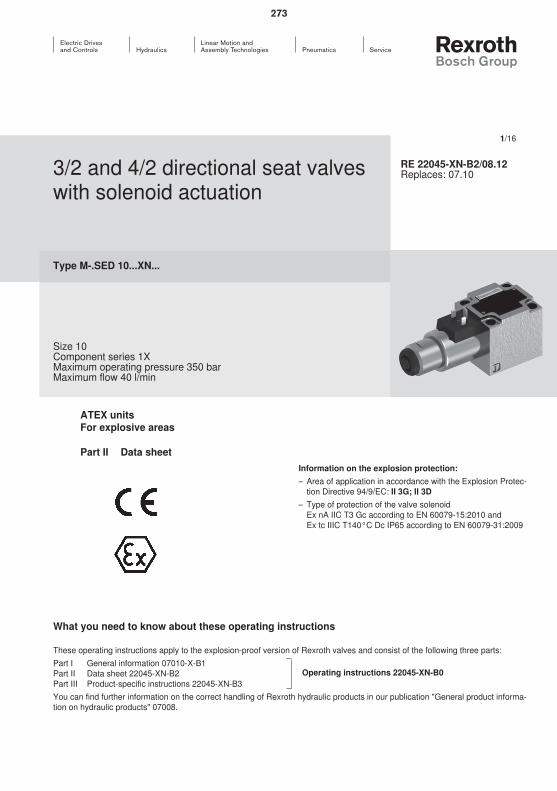
273

274
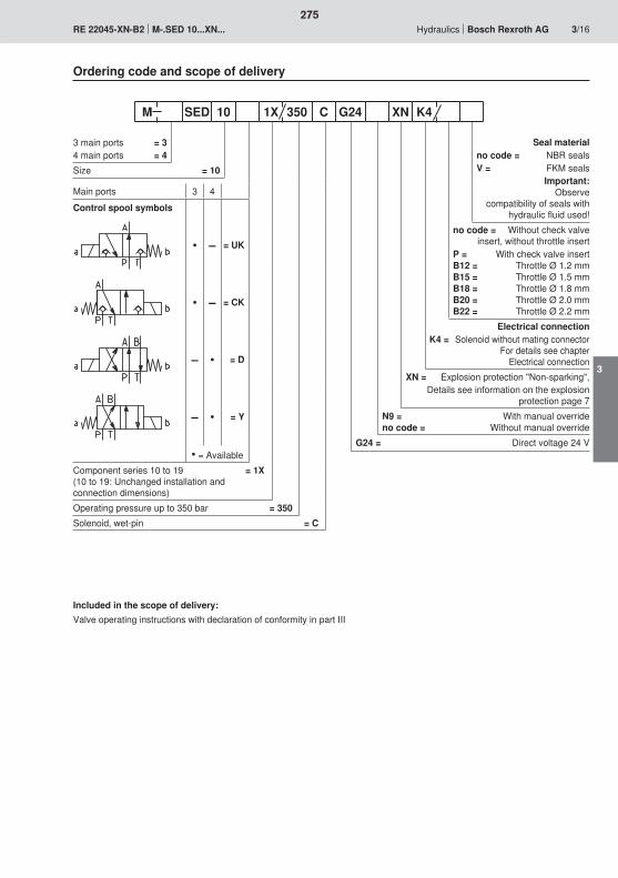
275
3
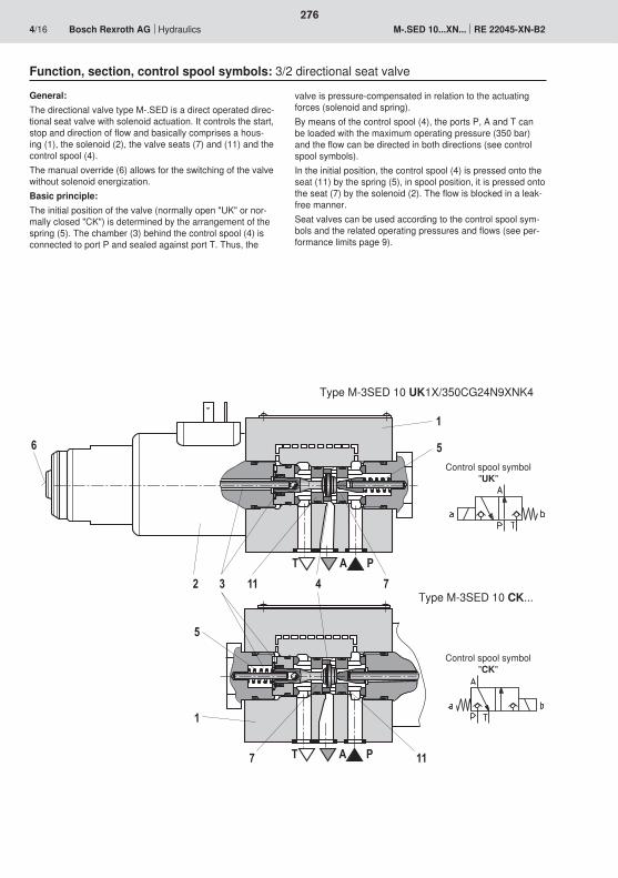
6
T A P
1
5
741132
5
1
7 11T A P
276
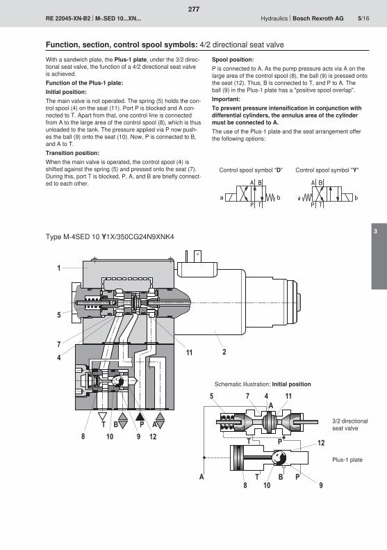
11
1
5
74
2
T B P A8 10 9 12
A T B P
T P
A5 7 4 11
12
9108
277
3

�
278
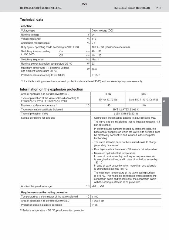
279
3
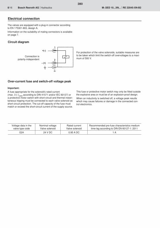
�;<�
<�;��
�
�
280
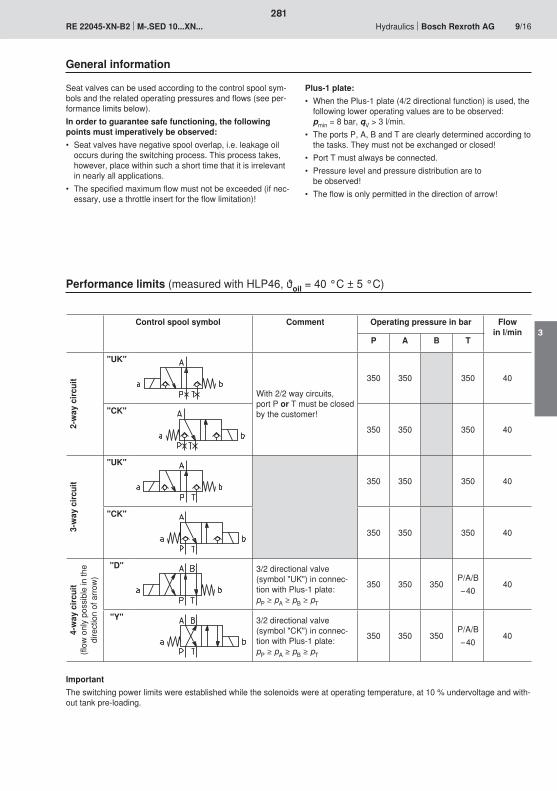
281
3

600
500
400
300
200
100
0 6 12 18 24 30 36 42
B12 B15 B18
B20
B22
30
25
20
15
10
5
0 5 10 15 20 25 30 35 40
134
230
25
20
15
10
5
0 5 10 15 20 25 30 35 40
13
4
2
282
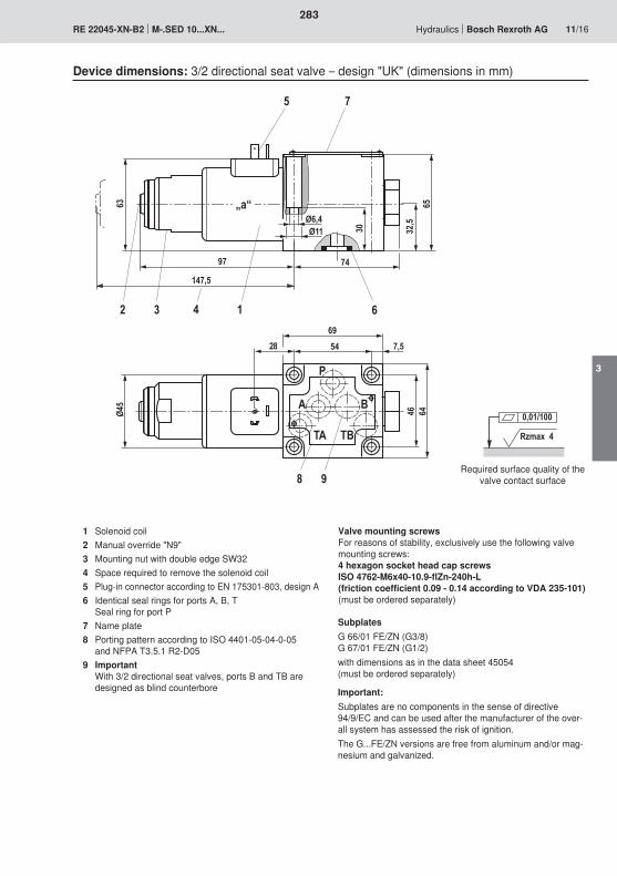
97
5
2 1
63 „a“
3
147,5
4
Ø45
46 64
7,55469
A
P
B
TA TB
8 9
74
6
Ø11Ø6,4
30 32,5
65
7
28
Rzmax 4
0,01/100
283
3
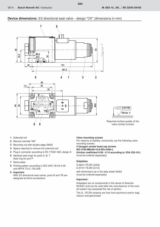
8 9
A
P
TA TB
B
6
64 46
7,5 5482
69
20 151
6532
,5
30
Ø6,4Ø11
Ø45
63
5
201,5
4 1 3 2
7
Rzmax 4
0,01/100
284
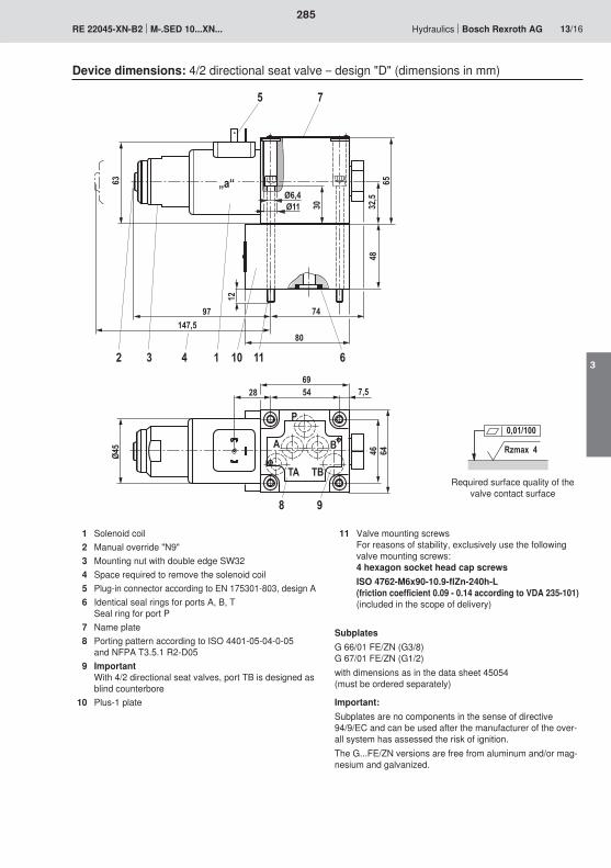
Rzmax 4
0,01/100
Ø45
8
611695428 7,5
46 64
P
A
TA TB
B
80
74
12
48
Ø11Ø6,4
30 32,5
65
97
5
2 1
63 „a“
3
147,5
4
7
10
9
285
3
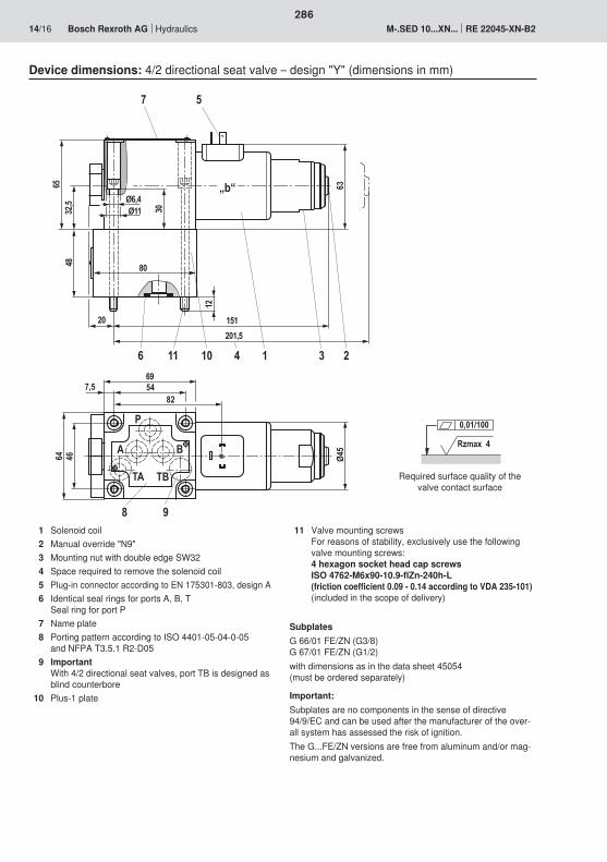
Ø45
8
6 11
7
P
BA
TA TB
10
64 46
7,5 5482
69
20 151
12
48 80
30Ø11Ø6,4
6532
,5
63
5
201,5
4 1 3 2
„b“
9
Rzmax 4
0,01/100
286

287
3

288
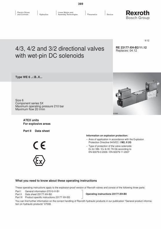
289
290

5 8� $
� '
5 8� $
� '
8
=��
=�'
>�"665 85 8� $
� '
5 85 8� $
� '
� $ � $
=�����
=�6����
=�&
=��
=��
=�,
=��
5 8� $
� '�
� $
� '�5 85 8
� $
� '�5
� $
� '�55
� '� 8
� '� 8 8
=�6'
=��
=��
=��
5 8� $
� '
� $
� '5 85
=��2
=�'�
291
3
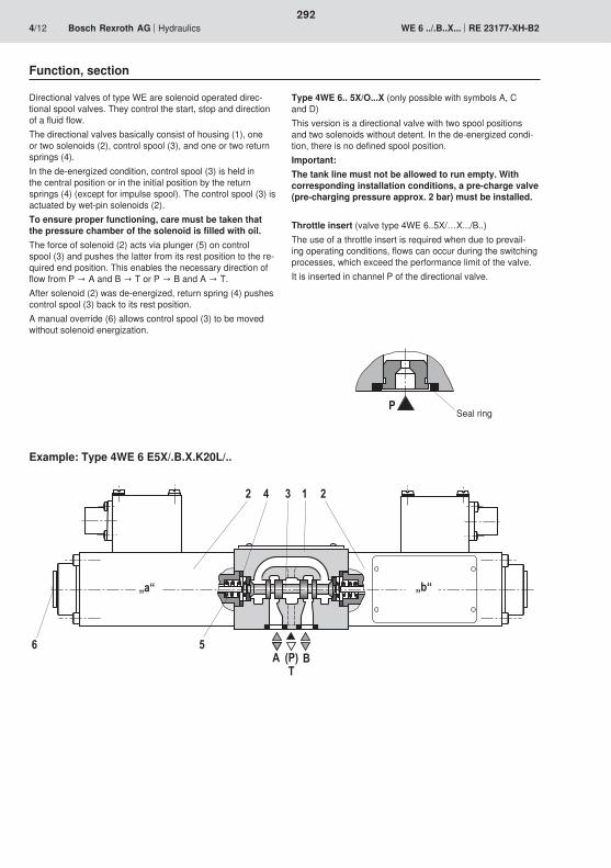
� � � �
0�
$';��
?5@ ?8@
�
292
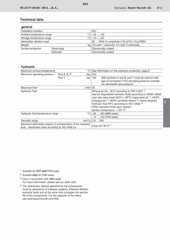
293
3

294
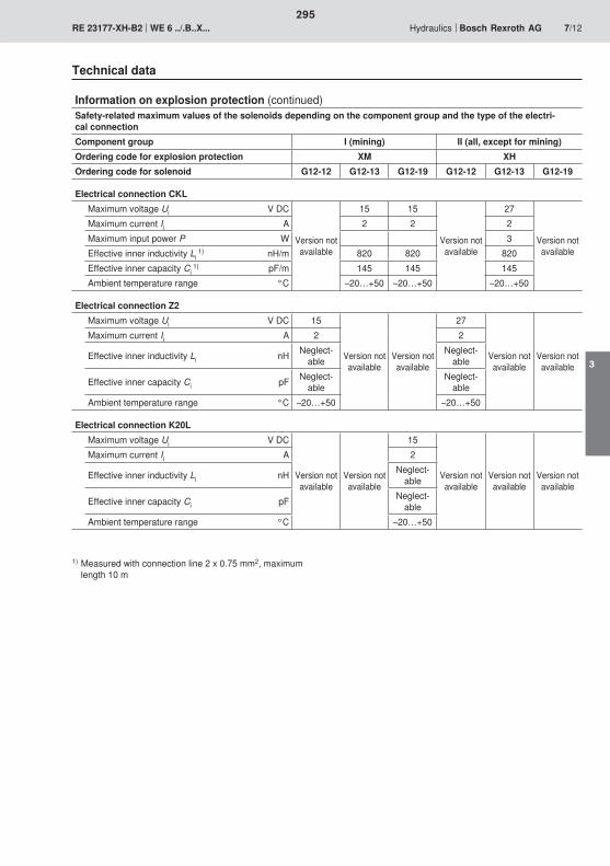
295
3
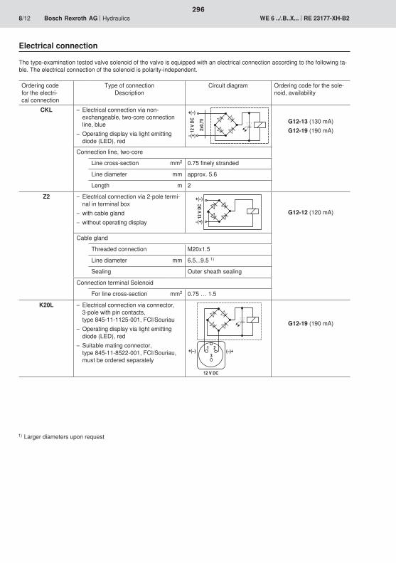
�*�)2
������
�
�;<�
<;��
������
��;<�
<;��
� �
��;<� ;<��
�������
296

��
�
�
0
3
��
�
��
�0
�3
���� ��
02
��
�
�
0
3
��
�
��
�0
�3
���� ��
��
�
������
���
�� �� ��
297
3

Rzmax 4
0,01/100
�
�0
�� 0
)�
� �0
�)
� '$
��)
��)
�
0
�
5
���
3003
8
�
22
�3��0
�
�
��
��
298
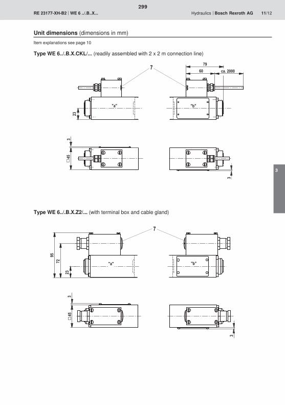
21
0� .56�����
8 5
�
�
2��
��
2�1
5 8
�
�2
299
3
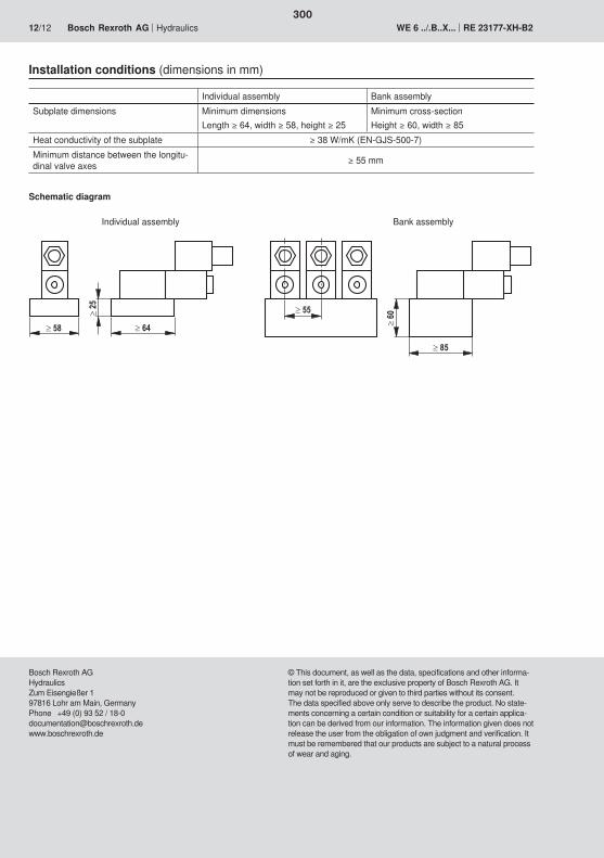
300

301
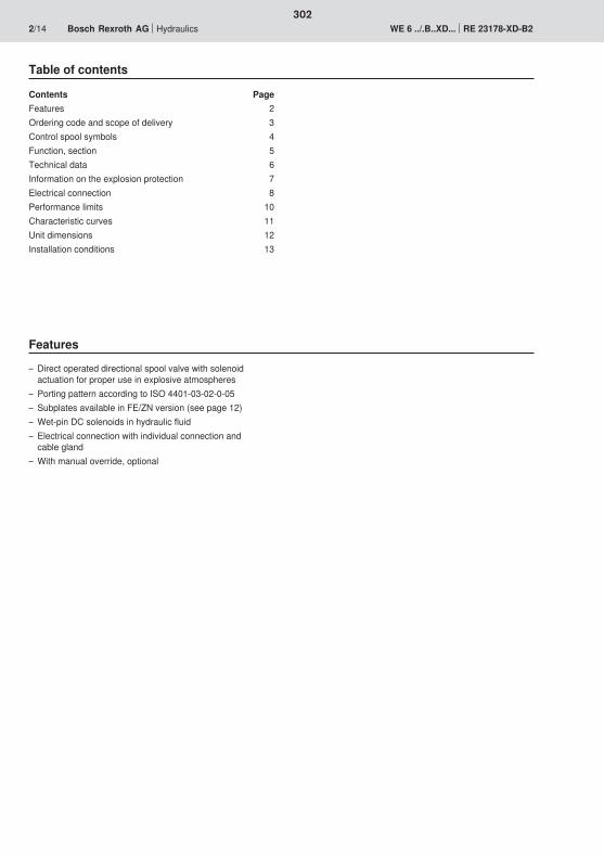
302
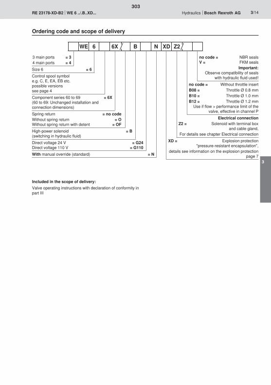
303
3
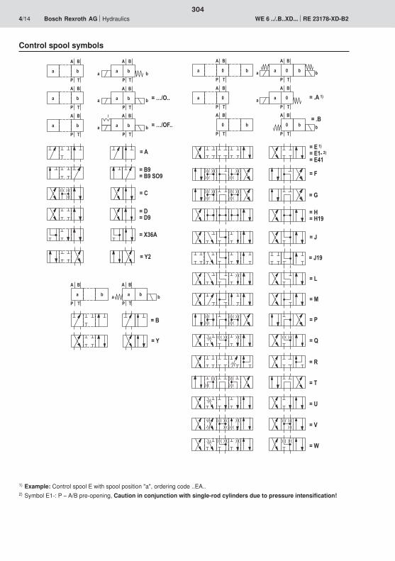
=��
=�$
=�&
=��
=��
� '
� $
5 � 5 �
� '
� $
8 85 8
� '
� $
5 � 5 �
� '
� $5
� '
� $
� �
� '
� $
8 8 8
=�6����
=�6'
� '
� $
5 8
� '
� $
5 8
� '
� $
5 8
5 8
� '
� $
=�>�"665 8
� '
� $
=�>�"�665 8
� '
� $
5 8
5 8
5 8
5 8
� '
� $
5 8
� '
� $5 8
=�'
=��
=��=��1
=��
=�'1=�'1�#"1
=��=�����
=���!���=���
=��
=��
=��
=��
=�,=�,�1
=��
=��
=�A
=���1=���
=���0�
304
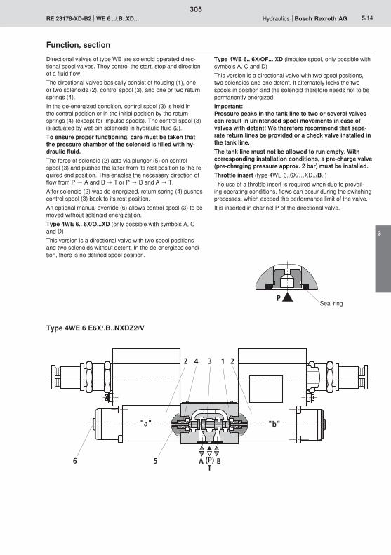
"b"
AT
B(P)
2 4 3 1 2
6 5
"a"
P
305
3
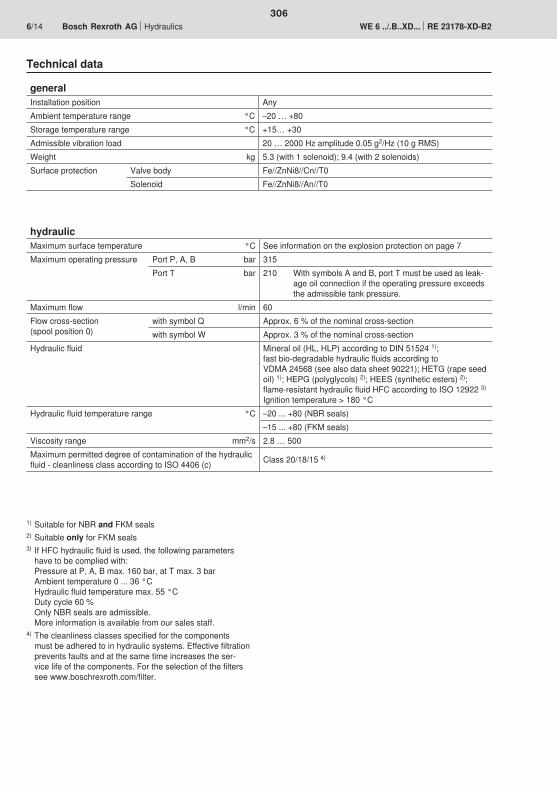
306
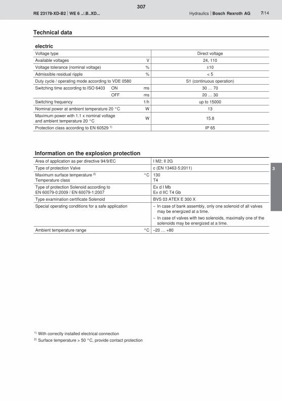
307
3
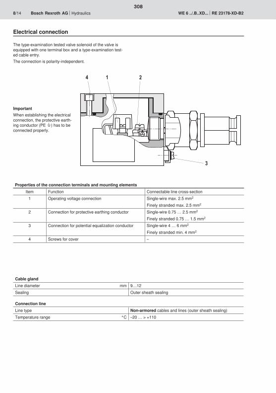
�
�
�
308
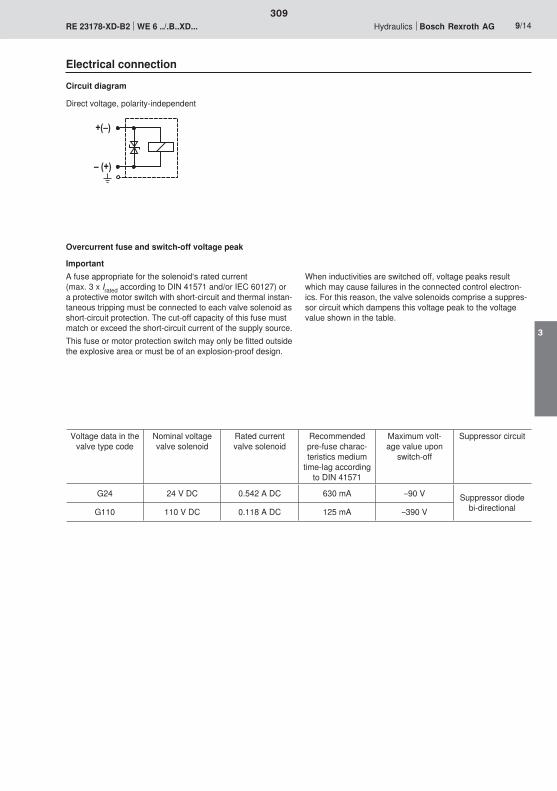
�;<�
<�;��
309
3
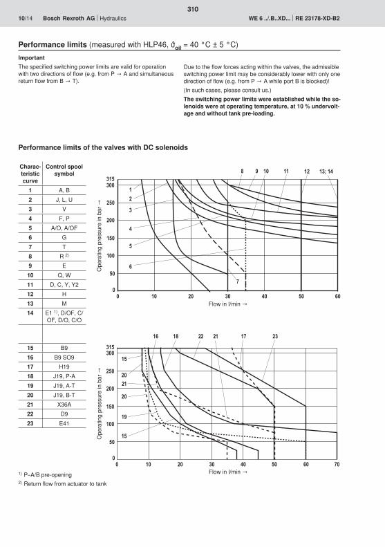
�
�
���
��
���
��
�����
� �� �� �� � � 0�
�
�1
�3 �2
�
�0
2�
��
����
���� ��
�
�
���
��
���
��
�����
� �� �� �� � � 0�
�
��7��������13
2
0
�
�
310
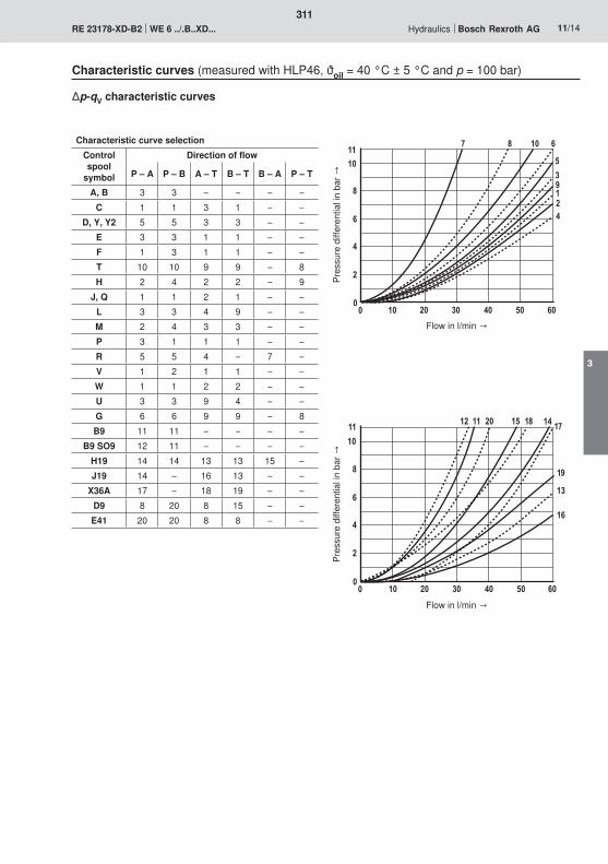
����
3
0
�
��� ����� � 0�
2 3 �� 0
�1��
�
��
��
3
0
�
��� ����� � 0�
���� � �
��
�
�0
�3 �2
�1
��
311
3
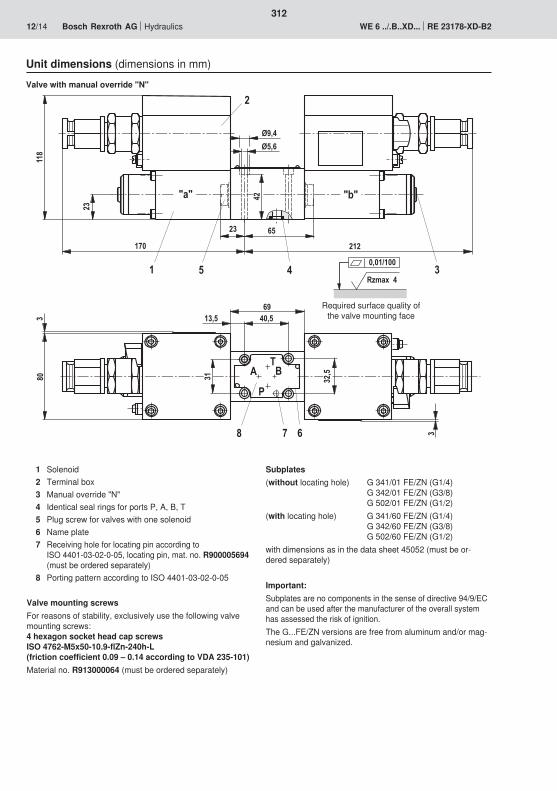
�2� ���
��
��3
)0
1)
��) �)01
� '
�
3 2
�� 0
0
8 5
$
3��
�
��)
�
��
�
�
�Rzmax 4
0,01/100
312
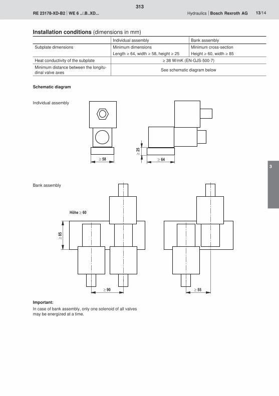
313
3

314
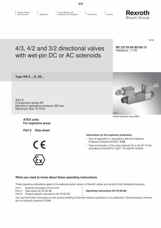
315
316

317
3
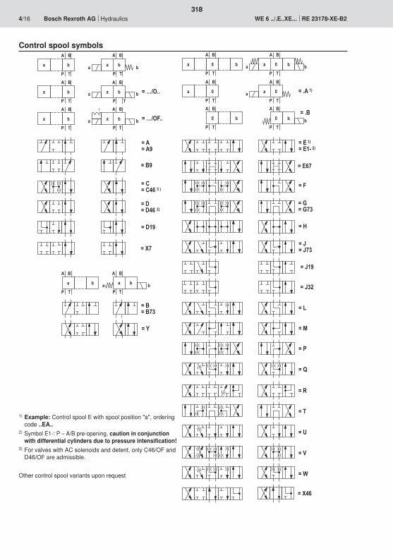
=��
=�$
=�&
=��
=��
� '
� $
5 � 5 �
� '
� $
8 85 8
� '
� $
5 � 5 �
� '
� $5
� '
� $
� �
� '
� $
8 8 8
=�6����
=�6'
� '
� $
5 8
� '
� $
5 8
� '
� $
5 8
5 8
� '
� $
=�>�"665 8
� '
� $
=�>�"�665 8
� '
� $
5 8
5 8
5 8
5 8
� '
� $
5 8
� '
� $5 8
=�'=�'2�
=��
=���1
=��=��0���
=��=��0����
=�'1
=��=��1
=��2
=�����
=���!���
=��02
=��
=��
=��
=��=��2�
=�,
=��=��2�
=��
=�A
=���1
=����
=��0
318
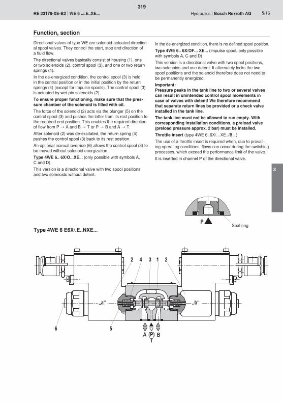
�
„a“ „b“
2 4 3 1 2
56A
TB(P)
319
3
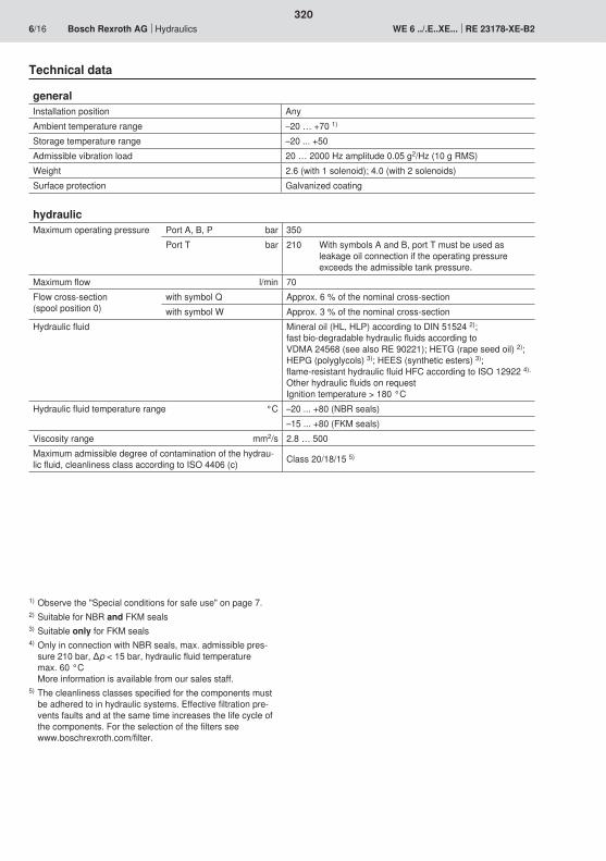
320
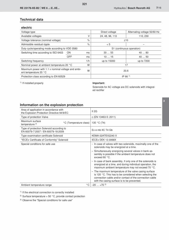
321
3
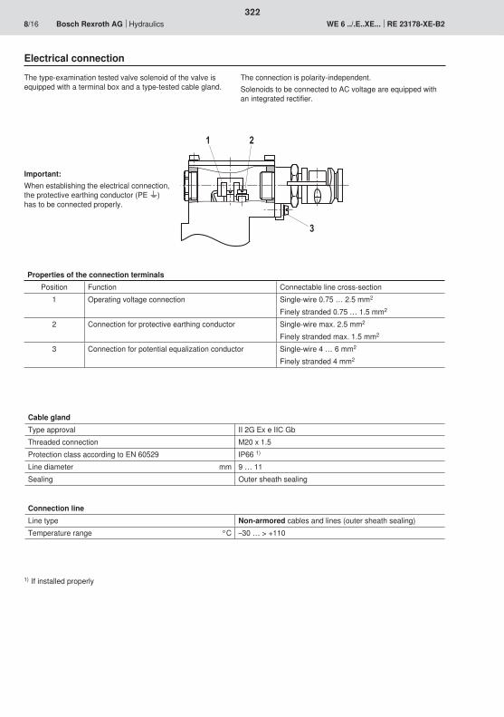
2
3
1
322

�;<�
<�;��
323
3

���
��
���
���
� �� �� �� � � 0� 2�
��
�
��
�0
�2
��
�
�1
��
�
��
�3
���0
�
��
���
��
���
���
� �� �� �� � � 0� 2�
��
�
��
�
�
� 3
2
0
1 �� �� ��
0
�
2
�
324
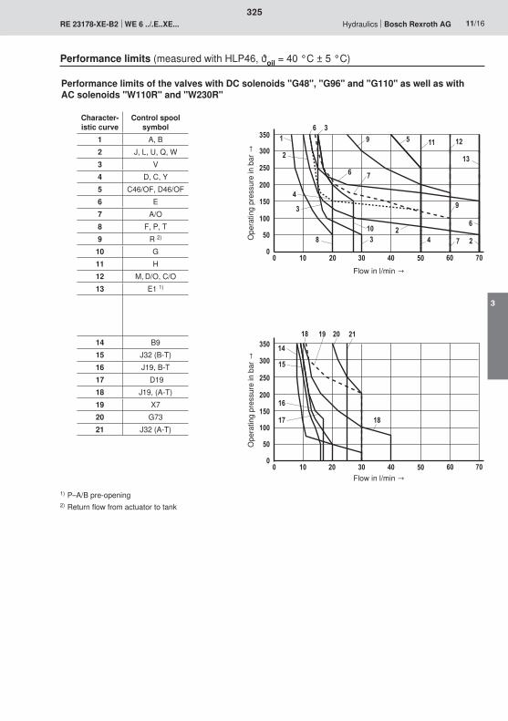
�
�
���
��
���
��
���
��
� �� �� �� � � 0� 2�
�
�
�2
�0
�����3 �1
�3
�
�
���
��
���
��
���
��
� �� �� �� � � 0� 2�
�
�
�
0 2
3
1
��
�� ��
��
0 �
1
2
0
��
�
325
3
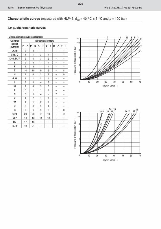
��
��
3
0
�
� �� ����� � 0� 2�
�� �1 �3�2�0
�� �� ��
��
��
��
��
3
0
�
� �� ����� � 0� 2�
2 3 �� 0 � 1�
�
326
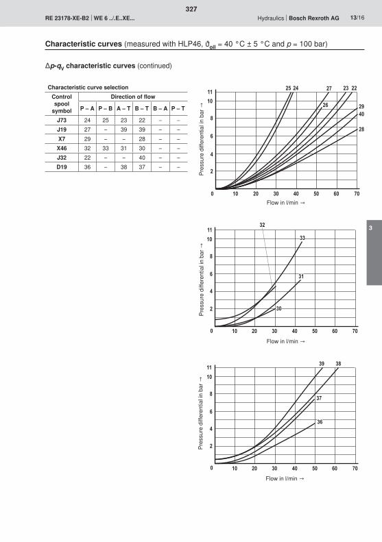
��
��
3
0
�
� �� ����� � 0� 2�
�2� � �� ��
�0 �1
�3
�
��
��
3
0
�
� �� ����� � 0� 2�
��
��
��
��
��
��
3
0
�
� �� ����� � 0� 2�
�3
�2
�0
�1
327
3
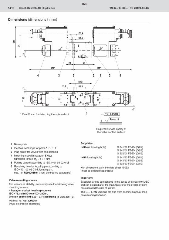
Rzmax 4
0,01/100
2
101
23
137* 179*
42
23 65
Ø9,4
Ø5,3
3 44 3
„b“
453
31
69,2
40,5
A BT
32,5
3
13,6
P
6
5 1
„a“„a“
74
328
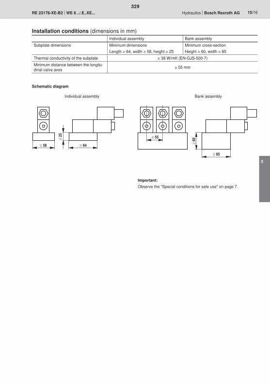
329
3

330
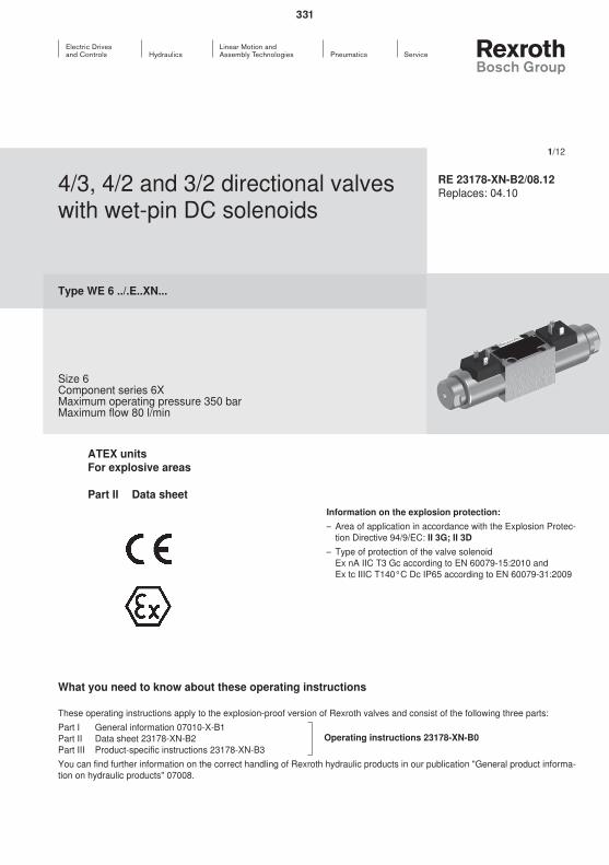
331
332
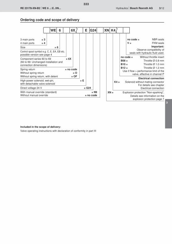
333
3

5 8
� $
� '
5 8
� $
� '
5 8
� $
� '
5 8
� $
� '
� $
� '
5 85 8
=��
=�'
=��
=��
=��
5 85 8� $
� '
>�"�66
>�"665 85 8
� $
� '
5 85 8� $
� '
5 8
� $
� '
�
� $
� '
�5 85 8
� $
� '
�5
� $
� '
�55
� $
� '
� 8
� $
� '
� 8 8
=��
=��
=�,
=��
=��
=���!���=������
=�6�����
=�6'
=��
=��
=�&
=�$
=��
=�A
=��
=��
334
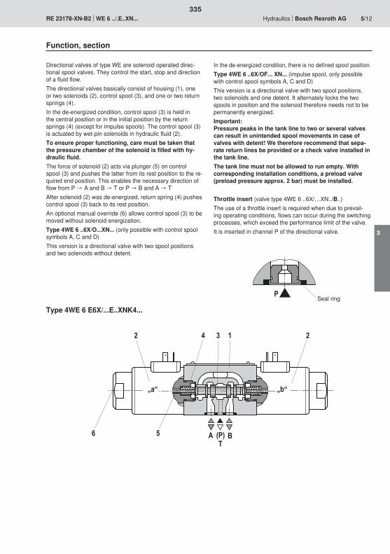
„a“ „b“
5
1342 2
AT
B(P)6
�
335
3
336
337
3
�;<�
<�;��
�
�
338

� �� �� �� � � 0� 2� 3�
���
��
���
��
���
��
�
�
�
1320
�
�
������ ��
��
��
3
0
�
� �� ����� � 0� 2�
2 3 �� 0 � 1�
�
339
3
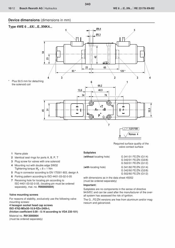
125 * 83 *
42
65
23
23
54
Ø9,4
Ø5,3
4 4323
69,2
45 32,5
40,5
31
6 1
A BT
P
7
13,6
34 76
5 5
Rzmax 4
0,01/100
340
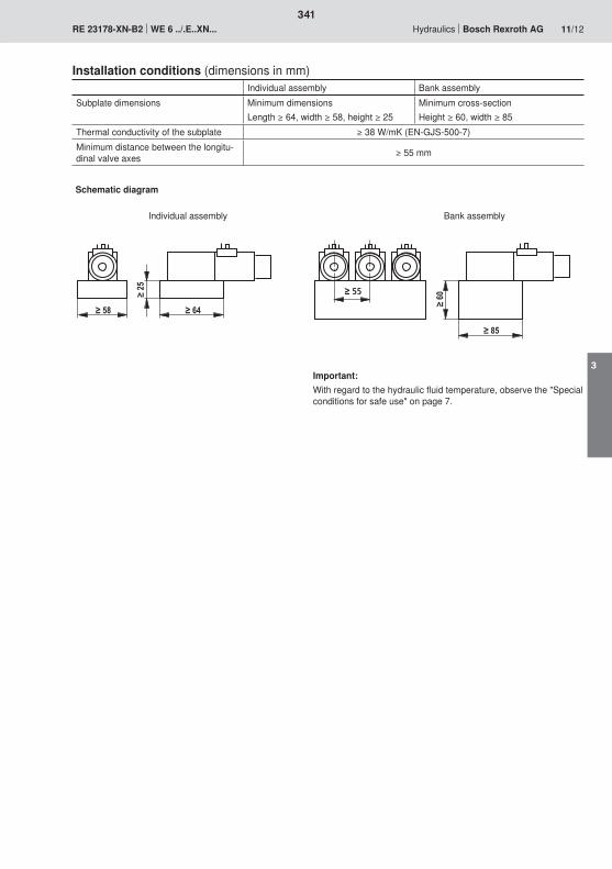
55
341
3

342
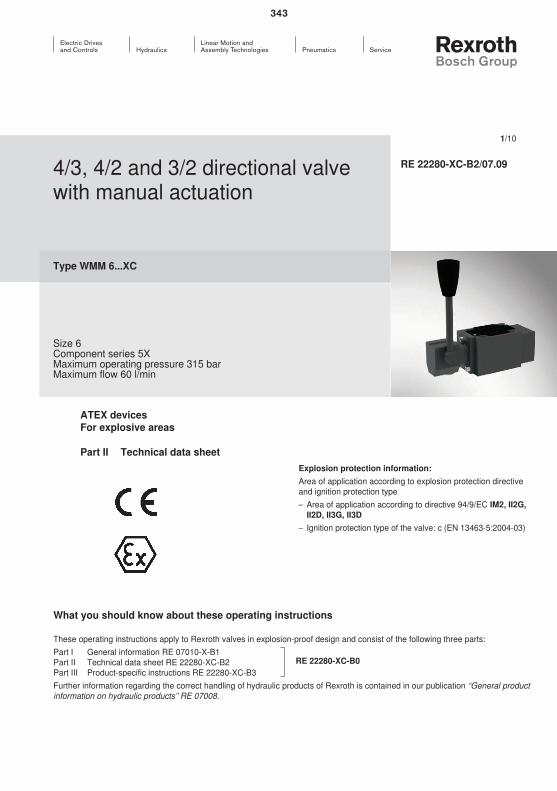
343
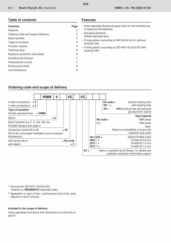
344
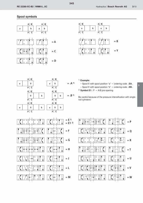
= L
= M
= E 1)
= F
= G
= H
= J
= E1 2)
= R
= T
= U
= V
= W
= P
= Q
= .B 1)
= .A 1)
A B
P T
a 0 a 0
A B
P T
A B
P T
0 b 0 b
A B
P T
A B
P T
a 0 a 0
A B
P T
b b
a b a b
A B
P T
A B
P T
= B
= Y
= A
= C
= D
A B
P T
a b a b
A B
P T
345
3
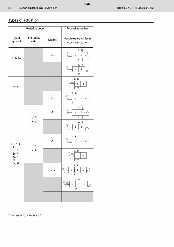
a b
A B
P T
a b
A B
P T
a b
A B
P T
a b
A B
P T
a 0
A B
P T
a 0
A B
P T
0 b
A B
P T
0 b
A B
P T
0 ba
A B
P T
0 ba
A B
P T
346
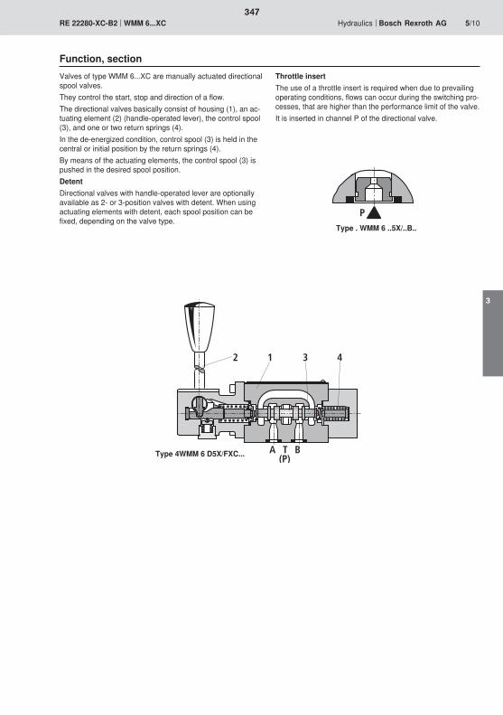
P
A T B(P)
2 1 3 4
347
3
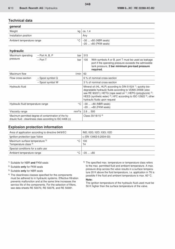
348
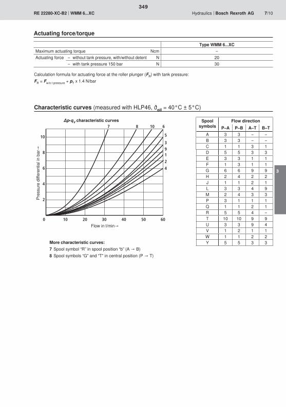
0 20 40 60
2
4
6
8
10
7 8 10 6
5
391
2
4
30 5010
349
3
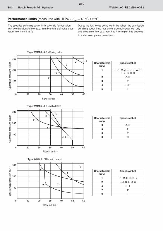
0 20 40 6030 5010
100
1
200
300
3
5
42
0 20 40 6030 5010
100
8200
300
6
35
3, 5
0 20 40 6030 5010
100
200
3001
7
4
9
2
350
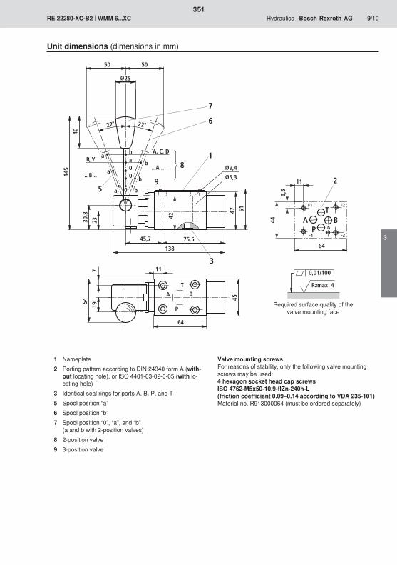
A B
T
P
40
145
30,8
23
45,7 75,5
138
47 51
9,4
5,3
50
2222
aba b00 b
a
a b
A, C, D
.. A ..B, Y
.. B ..
19
54
42
25
0
1
6
7
3
5
50
9
8
A BT
P
44
64
6,5
F1 F2
F3F4
G
11 2
117
64
45
0,01/100
Rzmax 4
351
3

352

353

354

= L
= M
= E 1)
= F
= G
= H
= J
= E1 2)
= A
= C
= D
A B
P T
a b a b
A B
P T
a b a b
A B
P T
A B
P T
= B
= Y
= R
= T
= U
= V
= W
= P
= Q
= .B 1)
= .A 1)
A B
P T
a 0 a 0
A B
P T
A B
P T
0 b 0 b
A B
P T
A B
P T
a 0 a 0
A B
P T
b b
355
3
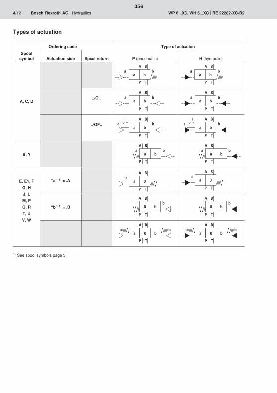
a b
A B
P T
baa b
A B
P T
ba
a bb
A B
P T
aa b
bA B
P T
a
a b
A B
P T
baa b
A B
P T
ba
a b
A B
P T
baa b
A B
P T
ba
a 0
A B
P T
a a 0
A B
P T
a
0 b
A B
P T
b0 b
A B
P T
b
0 b
A B
P T
ba
a0 b
A B
P T
ba
a
356
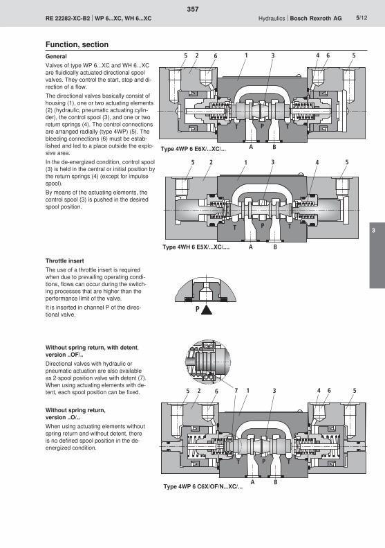
T T
A
P
B
35 2 1 4 5
T T
A
P
B
35 2 1 4 56 6
T T
A
P
B
35 2 1 4 576 6
P
357
3
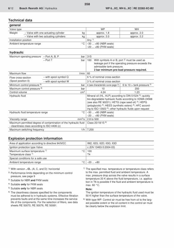
358
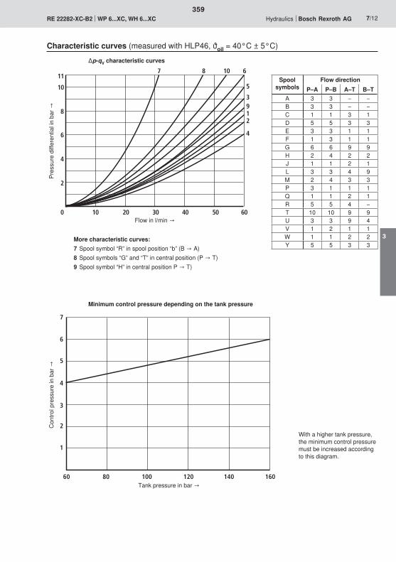
0 20 40 60
2
4
6
8
10
30 5010
117 8 10 6
5
3912
4
80
1
2
3
4
5
6
7
100 120 140 16060
359
3
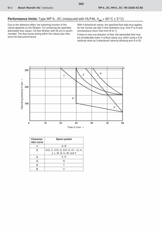
0 20 40 6030 5010
100
200
300
1
3
2
6
5 4
360
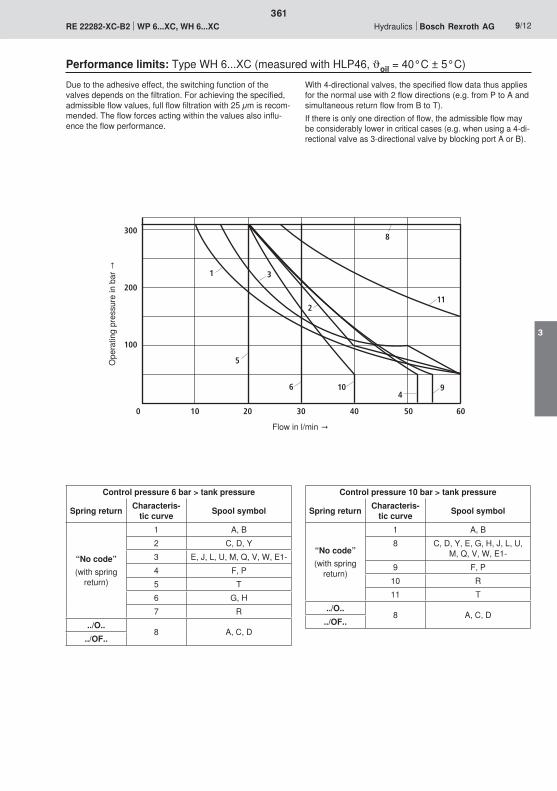
0 20 40 6030 5010
100
200
300
1 3
6
5
9
2
8
11
410
361
3
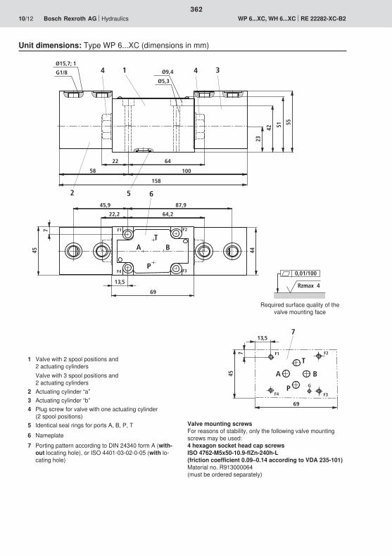
69
13,57
A B
T
P
F1 F2
F3F4
G
45
7
1 3Ø9,4
Ø5,3
G1/8
Ø15,7; 1
42
23
51
58
158
52
55
100
44
87,945,9
6
22 64
A BT
P
44
45
7
22,2 64,2
69
13,5
F1 F2
F3F4 0,01/100
Rzmax 4
362
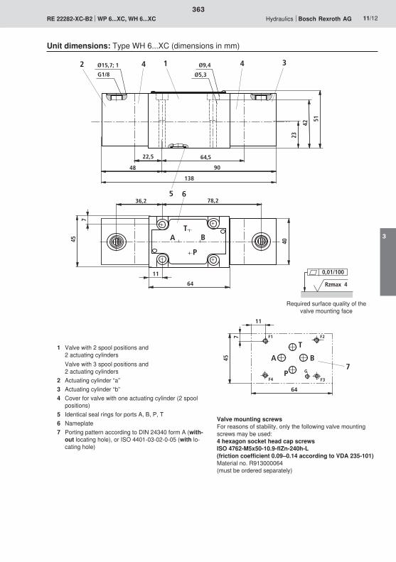
0,01/100
Rzmax 4
64
11
7A B
T
P
F1 F2
F3F4
G
45
7
1 3Ø9,4
Ø5,3G1/8
Ø15,7; 1
42
23
51
9048
138
5
2
TA B
P
40
36,2 78,26
4 4
22,5 64,5
45
7
11
64
363
3

364

365
366
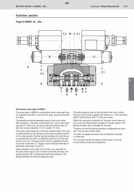
5.2 10 4 5.1
9
T
7
6
3.1
123.2
8
AP
BX Y
"a""b"
367
3
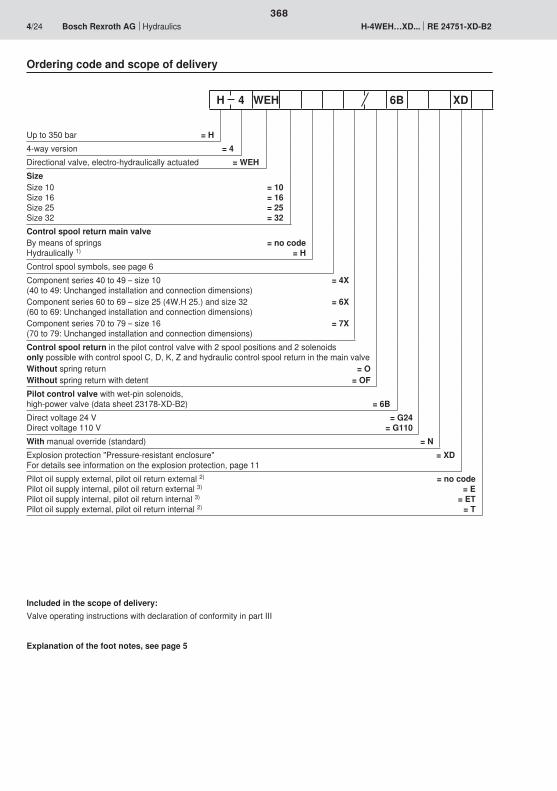
368
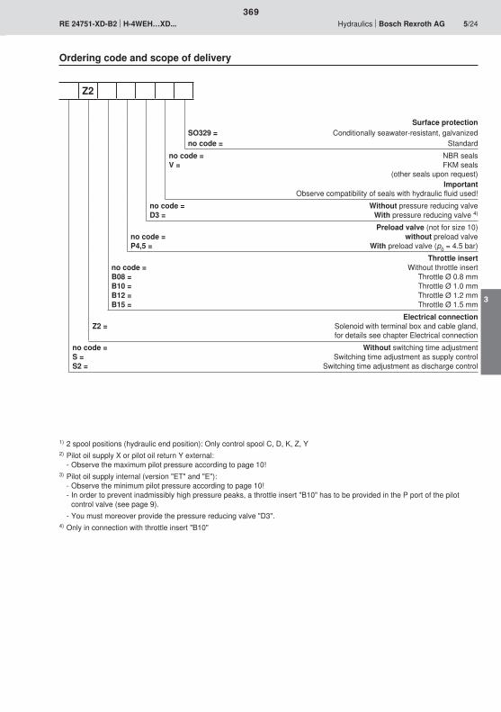
369
3
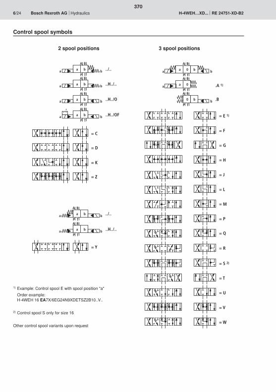
A B
P T
a ba b ../..
A B
P T
a ba b ..H../..
A B
P T
a ba b ..H../O
A B
P T
a ba b ..H../OF
= C
= D
= K
= Z
A B
P T
a ba b ../..
= Y
A B
P T
a ba b ..H../..
A B
P T
a 0a bb
A B
P T
a 0a .A 1)
A B
P T
0 bb .B
= E 1)
= G
= F
= J
= M
= P
= T
= S 2)
= U
= V
= Q
= W
= H
= L
= R
370
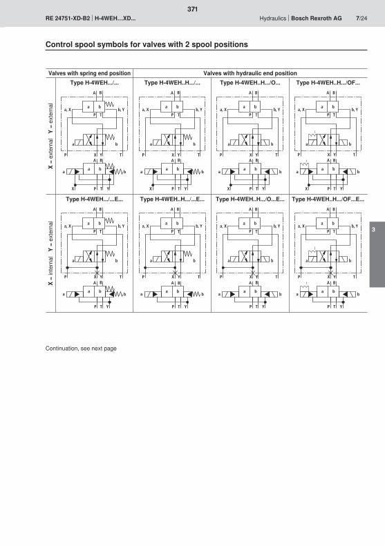
A B
a ba b
P TX Y
A B
P T
a ba, X b, Y
a b
P TYXA B
a ba b
P TX Y
A B
P T
a ba, X b, Y
a b
P TYXA B
a ba b
P TX Y
A B
P T
a ba, X b, Y
a b
P TYXA B
a ba b
P TX Y
A B
P T
a ba, X b, Y
a b
P TYX
A B
A B
P T
a ba, X b, Y
a b
P TYX
a ba b
P T Y
A B
A B
P T
a ba, X b, Y
a b
P TYX
a ba b
P T Y
A B
A B
P T
a ba, X b, Y
a b
P TYX
a ba b
P T Y
A B
A B
P T
a ba, X b, Y
a b
P TYX
a ba b
P T Y
371
3
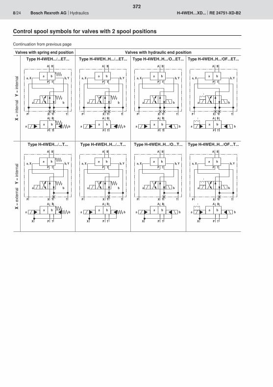
A B
A B
P T
a ba, X b, Y
a b
P TYX
a ba b
P T
A B
A B
P T
a ba, X b, Y
a b
P TYX
a ba b
P T
A B
A B
P T
a ba, X b, Y
a b
P TYX
a ba b
P T
A B
A B
P T
a ba, X b, Y
a b
P TYX
a ba b
P T
A B
P T
a ba, X b, Y
a b
P TYX
A B
a ba b
P TX
A B
P T
a ba, X b, Y
a b
P TYX
A B
a ba b
P TX
A B
P T
a ba, X b, Y
a b
P TYX
A B
a ba b
P TX
A B
P T
a ba, X b, Y
a b
P TYXA B
a ba b
P TX
372
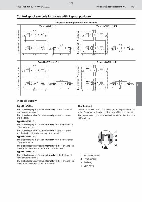
�
�
��
A B
a 0a, X b, Y
b
A B
a 0a b
b
P TX YP TX Y
a b
A B
a 0a, X b, Y
b
A B
a 0a b
b
P T
P TX Y
a b
A B
a 0a, X b, Y
b
A B
a 0a b
b
P T YP TX Y
a b
A B
a 0a, X b, Y
b
A B
a 0a b
b
P TXP TX Y
a b
373
3
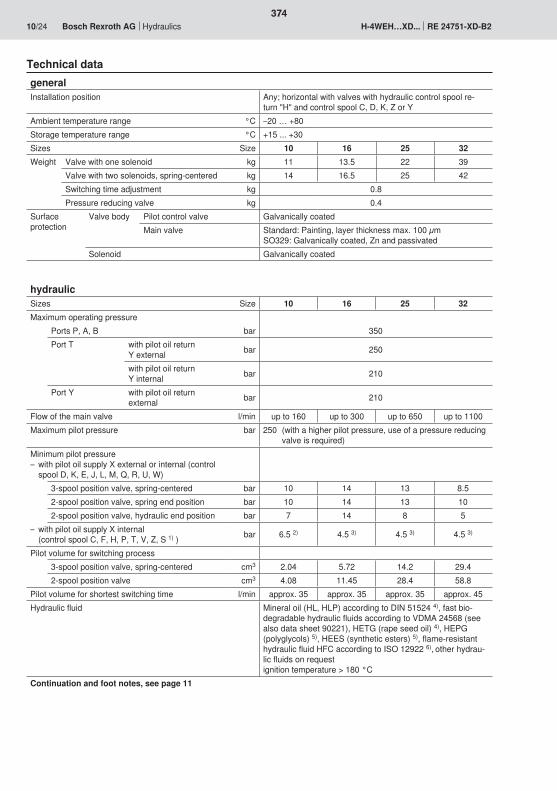
374
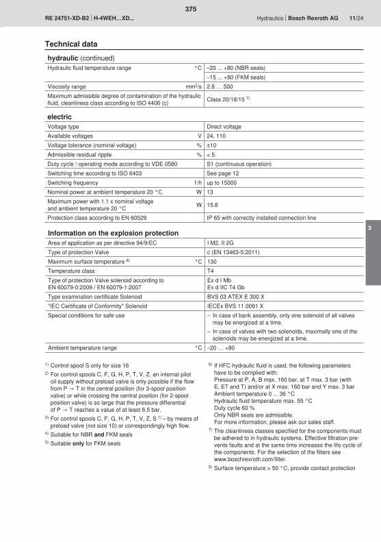
375
3
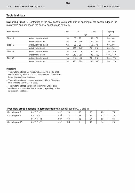
376

�
�
�
377
3
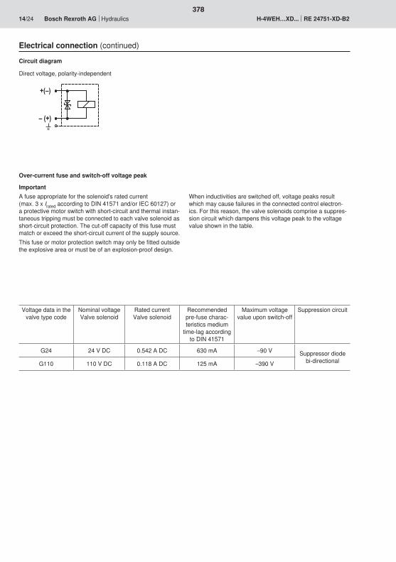
�;<�
<�;��
378
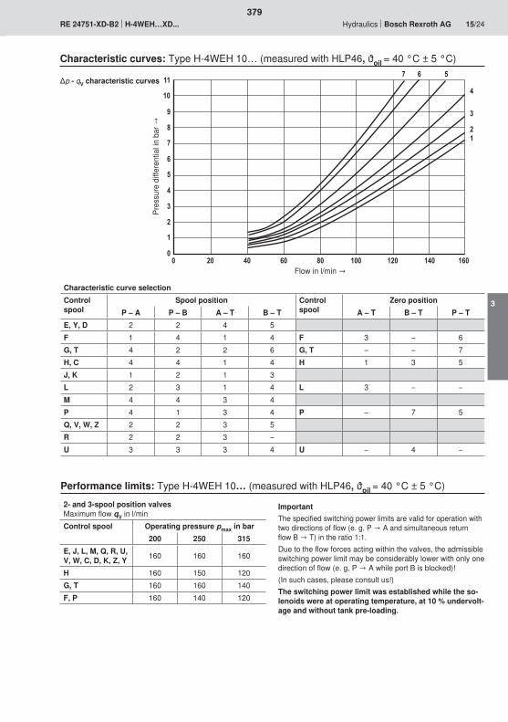
��
�
02��
��
1
3
2
0
�
�
�
�� �� � 0� 3� ��� ��� �� �0�
379
3
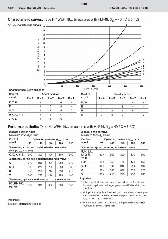
�
�
0
3
��
��
�
�0
�3
��
��
�
�0
�3
� � ��� �� ��� �� ���
3
2
0
���
380
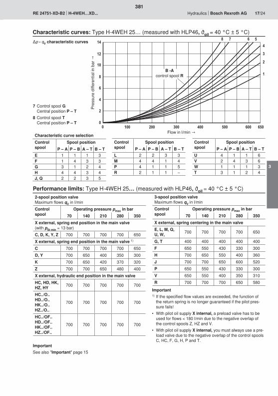
�
�
�
0
��
3
0
�
�� ��� ��� ��� ��
��
�
��
23
0�� 0�
381
3
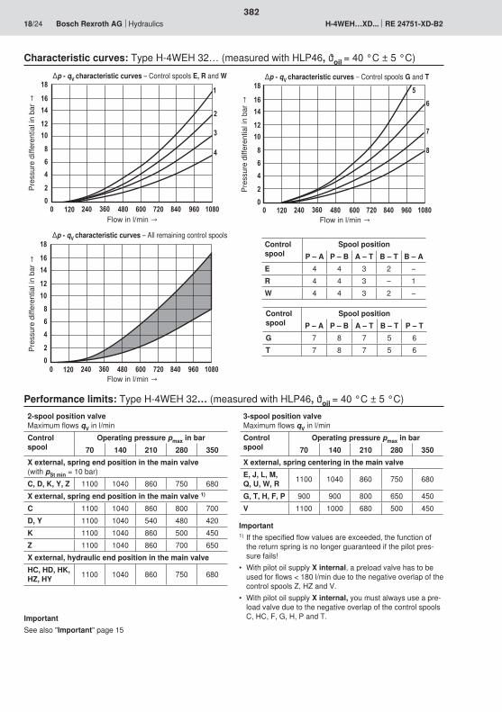
��
��
�
3
0
�
�� ��� �0� 3� 0���� 2��
�0
�3
3� 10� ��3�
0
2
3
��
��
�
3
0
�
�� ��� �0� 3� 0���� 2��
�0
�3
3� 10� ��3�
�
�
�
��
��
�
3
0
�
�� ��� �0� 3� 0���� 2��
�0
�3
3� 10� ��3�
382
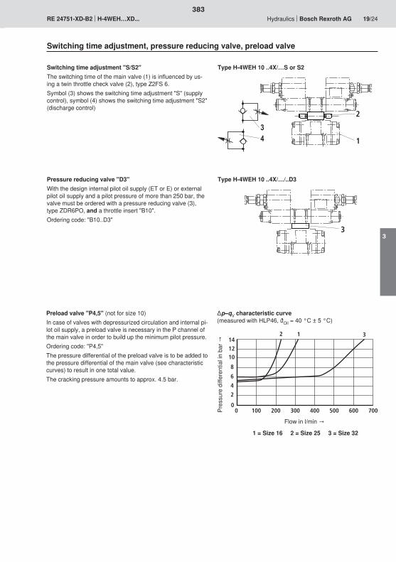
1
2
3
141210
8
6
4
2
00 100 200 300 400 500 600 700
12 3
�
383
3
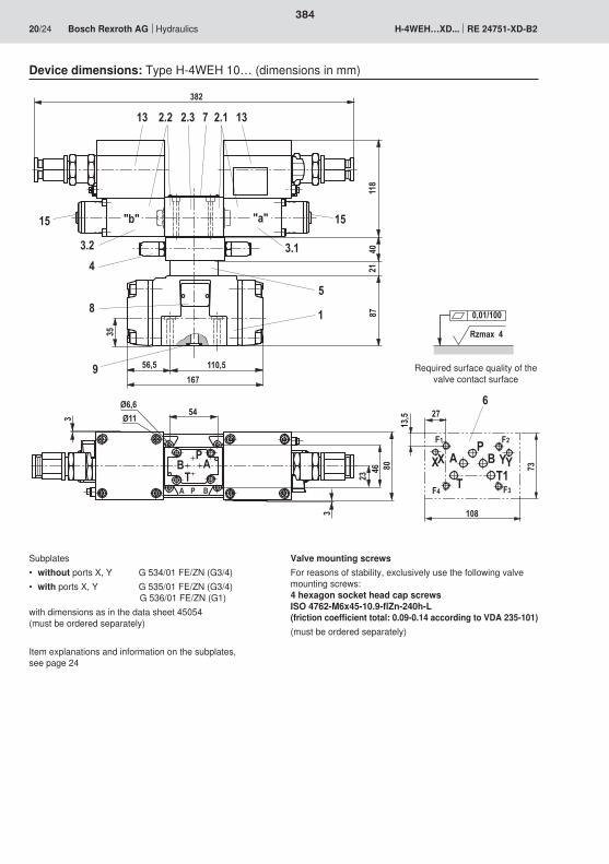
3�0��
� '
�
1�02
�
��
0)0
�3�
32��
���
3
�6��6���
�
�6�
3
�6�
�
���6�2
�
5 8
���)0)
�'�
$
0�2��
)
��3
�� '
$
� �$�
2�
�� ��
� ��
� �
�
�Rzmax 4
0,01/100
384
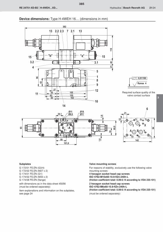
� ' �
�2 �
10 �31
��
���� 0�
�0��
�3�
���
3��
�6��6���
�
�6�
���6�2
�6�
�
�
�)� �� 0)0
�3 ��
��
' ��
����)0
1�
�)0
�
01)1
�)0
�'�
$
5 8
0
��
��
1
����
��
�
'�
�$
���
�
�
�0��
��
� Rzmax 4
0,01/100
385
3

'
��'
$ � �
1� ��2
���22
� �� �
�1����)
��
��0
�3
1
��
����
���
3��
�3�
�6�2�6��6���
��6�
�
�6�
��
�2�2�
11)
��
$
5 8
0
�� ��
�
'��
$
���
�
�
�0��
�2
�1
���
��
�
� Rzmax 4
0,01/100
386
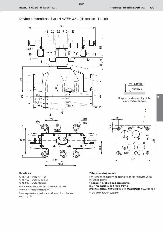
20
$
�1 ��
��
� �
� '
��)
�1�)
�1
21)
�12
�30)��)
��
3
1
��
��
��
�
��3
���
�3�
�6�2�6��6�
�6�
��
�
��
�
�6�
�30)2)�30)��)
2) ��)
�
5 8
�'�
$
0
�� ��
�'�
�
$
���
�
�
�0��
��
�2
��
���
��)
1 Rzmax 4
0,01/100
387
3
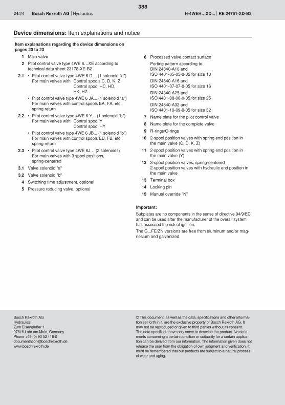
388

389
390
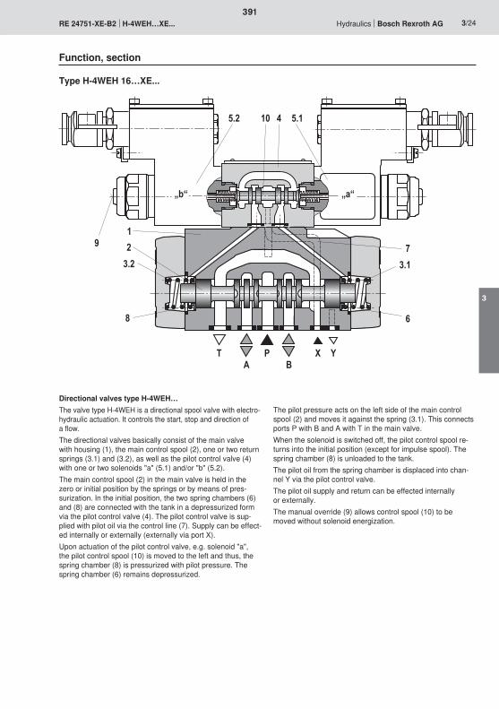
5.2 10 4 5.1
9
T
„b“ „a“
7
6
3.1
12
3.2
8
AP
BX Y
391
3

392
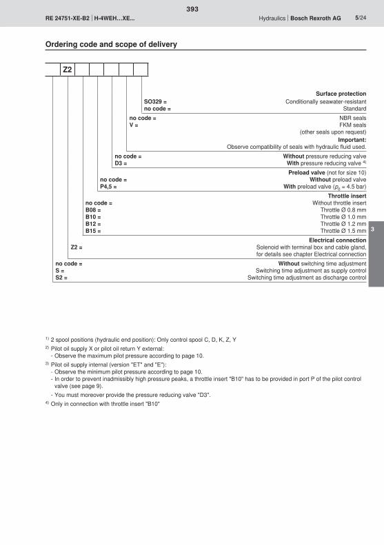
393
3
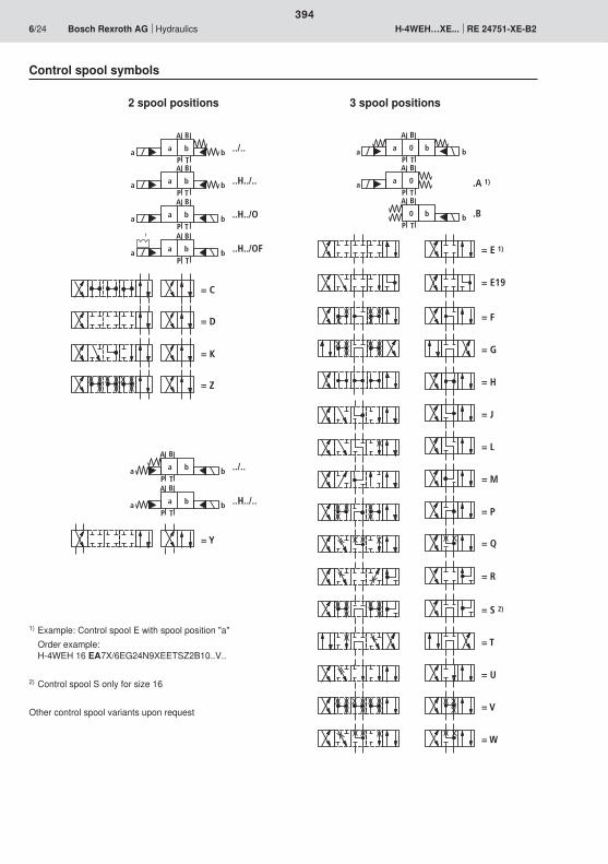
A B
P T
a ba b ../..
A B
P T
a ba b ..H../..
A B
P T
a ba b ..H../O
A B
P T
a ba b ..H../OF
= C
= D
= K
= Z
A B
P T
a ba b ../..
= Y
A B
P T
a ba b ..H../..
A B
P T
a 0a bb
A B
P T
a 0a .A 1)
A B
P T
0 bb .B
= E 1)
= G
= F
= J
= M
= P
= T
= S 2)
= U
= V
= Q
= W
= H
= L
= R
= E19
394
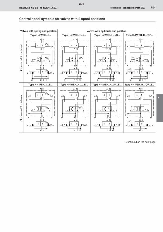
A B
a ba b
P TX Y
A B
P T
a ba, X b, Y
a b
P TYXA B
a ba b
P TX Y
A B
P T
a ba, X b, Y
a b
P TYXA B
a ba b
P TX Y
A B
P T
a ba, X b, Y
a b
P TYXA B
a ba b
P TX Y
A B
P T
a ba, X b, Y
a b
P TYX
A B
A B
P T
a ba, X b, Y
a b
P TYX
a ba b
P T Y
A B
A B
P T
a ba, X b, Y
a b
P TYX
a ba b
P T Y
A B
A B
P T
a ba, X b, Y
a b
P TYX
a ba b
P T Y
A B
A B
P T
a ba, X b, Y
a b
P TYX
a ba b
P T Y
395
3
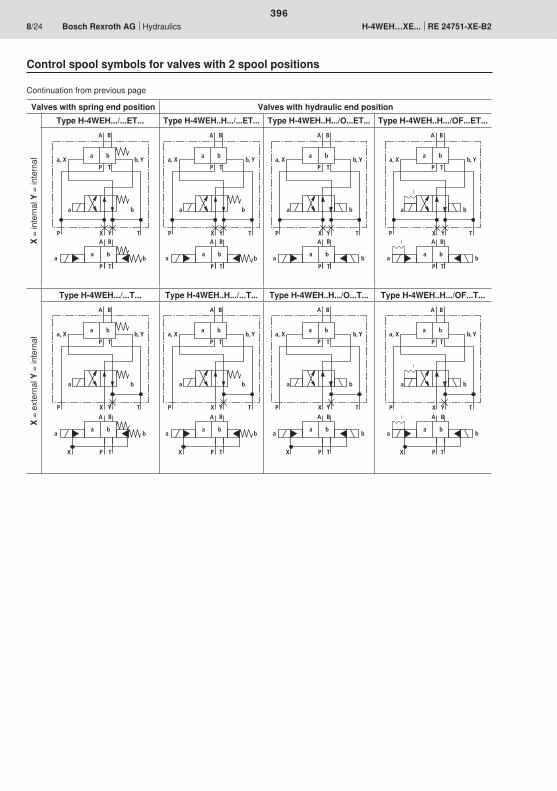
A B
A B
P T
a ba, X b, Y
a b
P TYX
a ba b
P T
A B
A B
P T
a ba, X b, Y
a b
P TYX
a ba b
P T
A B
A B
P T
a ba, X b, Y
a b
P TYX
a ba b
P T
A B
A B
P T
a ba, X b, Y
a b
P TYX
a ba b
P T
A B
P T
a ba, X b, Y
a b
P TYX
A B
a ba b
P TX
A B
P T
a ba, X b, Y
a b
P TYX
A B
a ba b
P TX
A B
P T
a ba, X b, Y
a b
P TYX
A B
a ba b
P TX
A B
P T
a ba, X b, Y
a b
P TYXA B
a ba b
P TX
396

A B
a 0a, X b, Y
b
A B
a 0a b
b
P TX YP TX Y
a b
A B
a 0a, X b, Y
b
A B
a 0a b
b
P T
P TX Y
a b
A B
a 0a, X b, Y
b
A B
a 0a b
b
P T YP TX Y
a b
A B
a 0a, X b, Y
b
A B
a 0a b
b
P TXP TX Y
a b
�
�
��
397
3
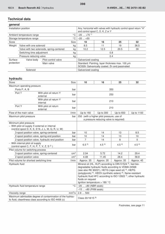
398
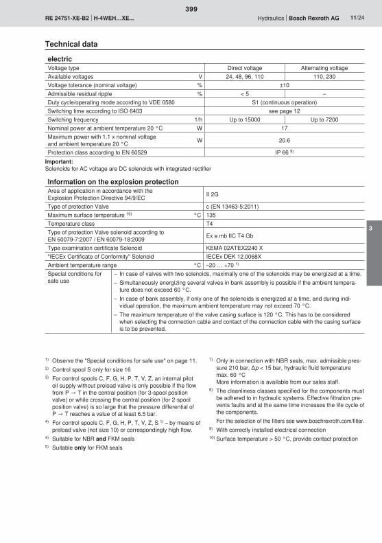
399
3
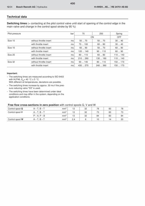
400
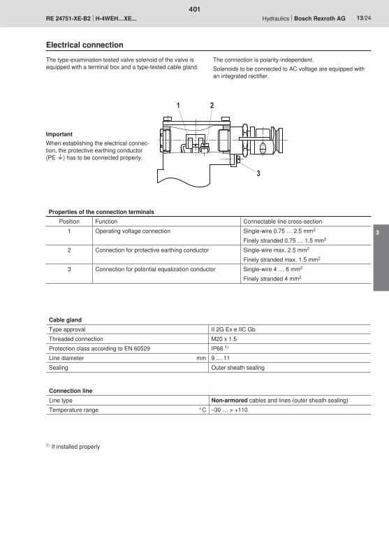
2
3
1
401
3
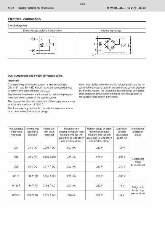
�;<�
<�;��
402

��
�
02��
��
1
3
2
0
�
�
�
�� �� � 0� 3� ��� ��� �� �0�
403
3
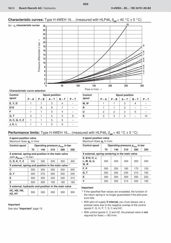
02468
10121416182022242628
0 50 100 150 200 250 300
87654321
10
9
404
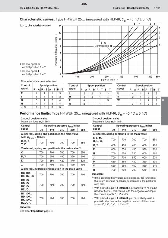
�
�
�
0
��
3
0
�
�� ��� ��� ��� ��
��
�
��
23
0�� 0�
405
3
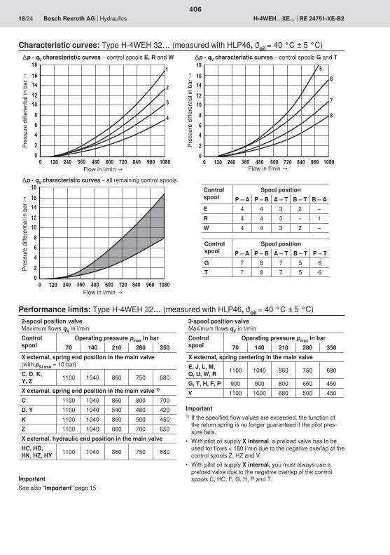
��
��
�
3
0
�
�� ��� �0� 3� 0���� 2��
�0
�3
3� 10� ��3�
0
2
3
��
��
�
3
0
�
�� ��� �0� 3� 0���� 2��
�0
�3
3� 10� ��3�
��
��
�
3
0
�
�� ��� �0� 3� 0���� 2��
�0
�3
3� 10� ��3�
�
�
�
406
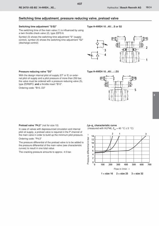
�
1
2
5
141210
8
6
4
2
00 100 200 300 400 500 600 700
12 3
407
3
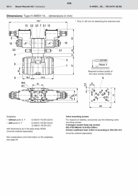
704523
AT B T
Y
AT B T
1
9
„b“ „a“
X
35
54Ø11Ø6,6
316 *
8721
4010
1
2.32.213
15
3.24
8
3.1
15
132.17
5
P
P
PABT
6
2713
,5
108
PA B
TY
T1
73
F1 F2
F4 F3
2
X
110,556,5
Rzmax 4
0,01/100
408
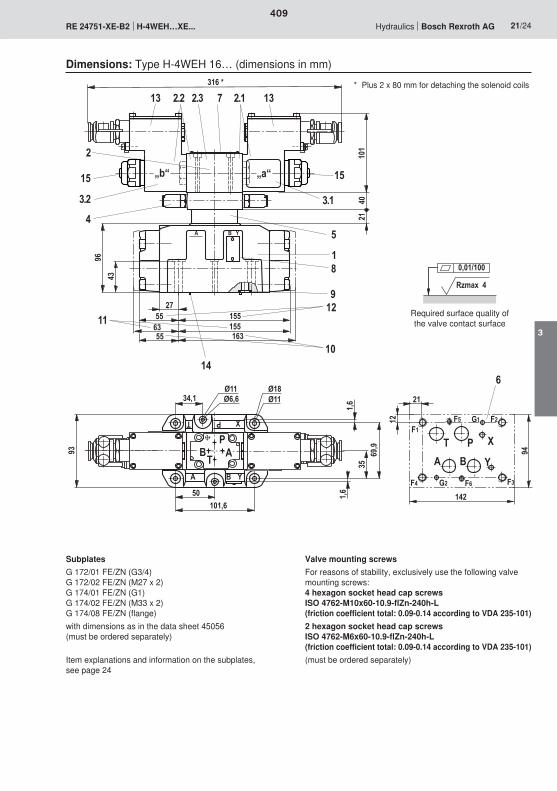
A B Y
2755 155
96 18
9
10
1211
63163
15555
316 *
4010
121
2.32.213
15
3.2
45
132.17
3.1
15
14
„b“ „a“
6
142
21
94
12
F1F2
PBA
XT
F3F4
Y
F5
F6G2
G1
2
43
34,1Ø11Ø6,6
Ø18Ø11
XP
B YA
50101,6
93
1,6
3569
,9
1,6
P
TB A
T
Rzmax 4
0,01/100
409
3

AXB
T P Y
92 117
13077
53Ø20Ø14
19225
252,5
225
126
18
9
10
1112
„b“ „a“
4010
121
316 *
2.172.32.213
153.2
4
5
15
3.1
13
14
P
TB A
7272
99,5
6
F1 F2
P
BAX
T
F3F4
Y
F5
F6G2
G7
195
120
21
14
241 Rzmax 4
0,01/100
410
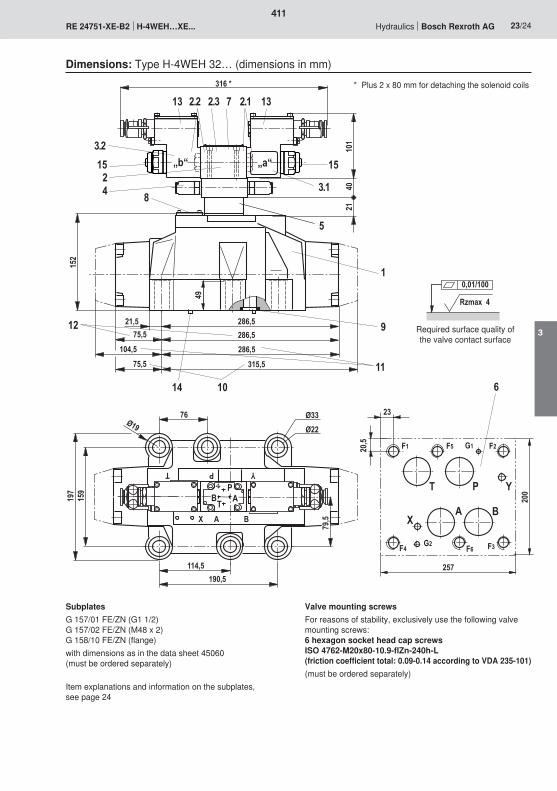
76
T
Ø19Ø33Ø22
P Y
X A B
114,5190,5
159
79,5
197
286,521,5
152
8
9
10
11
12
1
„b“ „a“
101
2140
316 *
2.172.32.2
3.1
5
13
15
4
13
153.2
P
TB A
286,575,5
286,5104,575,5 315,5
14 6
F1 F2
P
BAX
T
F3F4
Y
F5
F6G2
G1
257
23
200
20,5
249 Rzmax 4
0,01/100
411
3
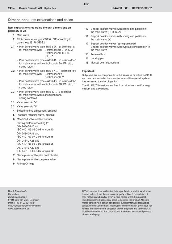
412

1/12
Pressure-reducing valves, directly operated
Types DR 6 DP...XC and ZDR 6 D...XC
Nominal size 6Unit series 5X (DR 6...) and 4X (ZDR 6...)Maximum operating pressure, primary 315 bar (DR 6... and ZDR 6...)Maximum flow rates 60 l/min (DR 6...) and 50 l/min (ZDR 6...)
RE 26564-XC-B2/06.09Replaces: 12.05
Information on explosion protection:
Range of application in accordance with the Explosion Protection Directive and type of protection
– Range of application as per Directive 94/9/EG IM2, II2G
– Type of protection of valve: c (EN 13463-5:2004-03)
ATEX units For potentially explosive atmospheres Part II Technical Data Sheet
What you need to know about these Operating Instructions
These Operating Instructions apply to the explosion-proof version of Rexroth valves, and consist of the following three parts:
Part I General Information RE 07010-X-B1 Part II Technical Data Sheet RE 26564-XC-B2 Part III Product-specific Instructions RE 26564-XC-B3
You can find further information on the correct handling of Rexroth hydraulic products in our publication “General Product Information on Hydraulic Products”, RE 07008.
RE 26564-XC-B0
H7389
413
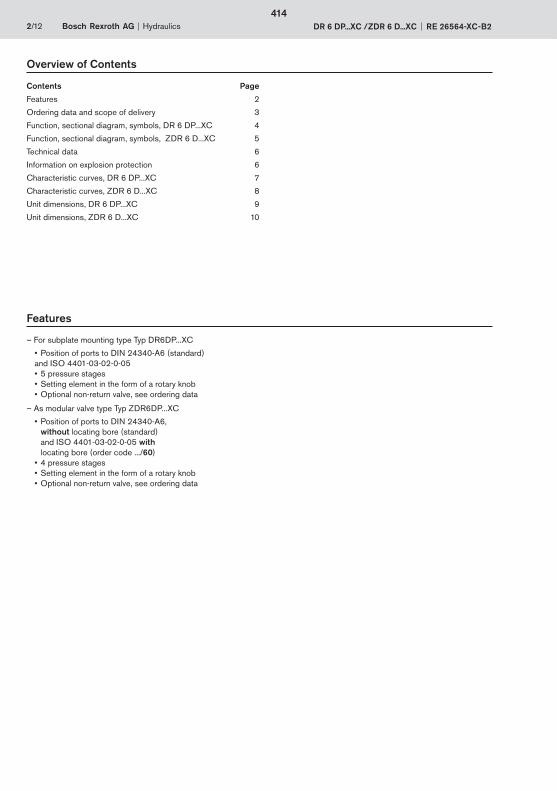
2/12 Bosch Rexroth AG Hydraulics DR 6 DP...XC /ZDR 6 D...XC RE 26564-XC-B2
Overview of Contents
Contents Page
Features 2
Ordering data and scope of delivery 3
Function, sectional diagram, symbols, DR 6 DP...XC 4
Function, sectional diagram, symbols, ZDR 6 D...XC 5
Technical data 6
Information on explosion protection 6
Characteristic curves, DR 6 DP...XC 7
Characteristic curves, ZDR 6 D...XC 8
Unit dimensions, DR 6 DP...XC 9
Unit dimensions, ZDR 6 D...XC 10
Features
– For subplate mounting type Typ DR6DP...XC • Position of ports to DIN 24340-A6 (standard)
and ISO 4401-03-02-0-05• 5 pressure stages• Setting element in the form of a rotary knob• Optional non-return valve, see ordering data
– As modular valve type Typ ZDR6DP...XC
• Position of ports to DIN 24340-A6, without locating bore (standard) and ISO 4401-03-02-0-05 with locating bore (order code .../60)
• 4 pressure stages• Setting element in the form of a rotary knob• Optional non-return valve, see ordering data
414
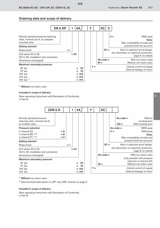
Hydraulics Bosch Rexroth AGRE 26564-XC-B2 DR 6 DP...XC /ZDR 6 D...XC 3/12
Ordering data and scope of delivery
Included in scope of delivery:
Valve operating instructions with Declaration of Conformity in Part III
Directly operated pressure-reducing valve, nominal size 6, as subplate-mounted valve
Setting elementRotary knob = 1
Unit series 50 to 59 = 5X(50 to 59: installation and connection dimensions unchanged)
Maximum secondary pressure 25 bar = 25 75 bar = 75 150 bar = 150 210 bar = 210 315 bar 1) = 315
V = FKM sealsNote:
Take compatibility of seals and pressure fluid into account !
XC = Valve in explosion-proof design,see information on explosion protection,
page 6, for details
No code = With non-return valveM = Without non-return valve
Y = Internal control oil supplyExternal leakage oil return
1) Without non-return valve
DR 6 DP 1 5X Y XC V
Directly operated pressure- reducing valve, nominal size 6, as modular valve
Pressure reductionin channel A2 = Ain channel B2 1) 2) = Bin channel P1 1) 2) = P
Setting elementRotary knob = 1
Unit series 40 to 49 = 4X(40 to 49: installation and connection dimensions unchanged)
Maximum secondary pressure 25 bar = 25 75 bar = 75 150 bar = 150 210 bar = 210
No code = Without locating bore
/60 = With locating bore
No code = NBR-seals V = FKM-seals
Note:Take compatibility of seals and
pressure fluid into account !
XC = Valve in explosion-proof design,see information on explosion protection,
page 6, for details
No code = With non-return valve (only possible with pressure
reduction in channel A2)M = Without non-return valve
Y = Internal control oil supplyExternal leakage oil return
ZDR 6 D 1 4X Y XC
1) Without non-return valve2) See functional description of „DP“ and „DB“ versions on page 5
Included in scope of delivery:
Valve operating instructions with Declaration of Conformity in Part III
415
3
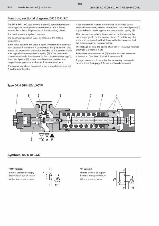
PAT(Y)
1 8 5 2 7 3 4
6
4/12 Bosch Rexroth AG Hydraulics DR 6 DP...XC /ZDR 6 D...XC RE 26564-XC-B2
Function, sectional diagram, DR 6 DP...XC
Type DR 6 DP1-5X/...XCYV
The DR 6 DP…XC type valve is a directly operated pressure-reducing valve in subplate-mounted design. It is a 3-way version, i.e. it limits the pressure of the secondary circuit.
It is used to reduce system pressure.
The secondary pressure is set by means of the setting element (4).
In the initial position, the valve is open. Pressure fluid can flow from channel P to channel A unimpeded. The pilot line (6) also makes the pressure in channel A available to the piston surface area opposite the compression spring (3). If the pressure in channel A exceeds the value set at the compression spring (3),the control piston (2) moves into the control position and keeps the set pressure in channel A at a constant level.
The control signal and control oil arrive internally from channel A via the pilot line (6).
If the pressure in channel A continues to increase due to external forces being exerted on the load, the control piston (2) is pushed even harder against the compression spring (3).
This causes channel A to be connected to the tank via the metering edge (8) on the control piston (2). In this way, the amount of pressure fluid that flows to the tank ensures that the pressure cannot rise any further.
The leakage oil from the spring chamber (7) is always returned externally via channel T (Y).
An optional non-return valve (5) may be installed to ensure a free return flow from channel A to channel P.
A gage connection (1) enables the secondary pressure to be monitored (see page 9 for connection dimensions).
Symbols, DR 6 DP...XC
“YM” version
Internal control oil supplyExternal leakage oil return
Without non-return valve
”Y” version
Internal control oil supplyExternal leakage oil return
With non-return valve
416
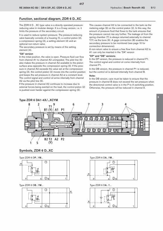
(Y)B2 T2 A2 P2
B1 (Y) A1 P1T1
1
2 3 4
5
6 78 9
Hydraulics Bosch Rexroth AGRE 26564-XC-B2 DR 6 DP...XC /ZDR 6 D...XC 5/12
Function, sectional diagram, ZDR 6 D...XC
The ZDR 6 D…XC type valve is a directly operated pressure-reducing valve in modular design. It is a 3-way version, i.e. it limits the pressure of the secondary circuit.
It is used to reduce system pressure. The pressure-reducing valve basically consists of a housing (1), a control piston (2), a compression spring (3), a setting element (4) and an optional non-return valve. The secondary pressure is set by means of the setting element (4).
“DA” version In the initial position, the valve is open. Pressure fluid can flow from channel A1 to channel A2 unimpeded. The pilot line (5) also makes the pressure in channel A2 available to the piston surface area opposite the compression spring (3). If the pres-sure in channel A2 exceeds the value set at the compression spring (3), the control piston (2) moves into the control position and keeps the set pressure in channel A2 at a constant level. The control signal and control oil arrive internally from channel A2 via the pilot line (5). If the pressure in channel A2 continues to increase due to external forces being exerted on the load, the control piston (2) is pushed even harder against the compression spring (3).
This causes channel A2 to be connected to the tank via the metering edge (9) on the control piston (2). In this way, the amount of pressure fluid that flows to the tank ensures that the pressure cannot rise any further. The leakage oil from the spring chamber (7) is always returned externally to channel T(Y) via the bore (6). A gage connection (8) enables the secondary pressure to be monitored (see page 10 for connection dimensions).A non-return valve to ensure a free flow from channel A2 to A1 can only be inserted in the “DA” version
“DP” and “DB” versions In the DP version, the pressure is reduced in channel P1. The control signal and control oil come internally from channel P1.
In the DB version, the pressure in channel P1 is reduced, but the control oil is derived internally from channel B.
Note:In the DB version, care must be taken to ensure that the pressure in channel B does not exceed the set pressure when the directional control valve is in the P to A switching position. Otherwise, the pressure will be reduced in channel A.
Symbols, ZDR 6 D...XC
Type ZDR 6 DP...YM... Type ZDR 6 DA...YM...
Type ZDR 6 DB...YM... Type ZDR 6 DA...Y...
Type ZDR 6 DA1-4X/...XCYM
417
3
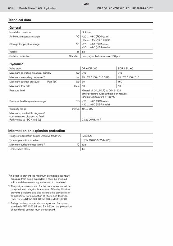
6/12 Bosch Rexroth AG Hydraulics DR 6 DP...XC /ZDR 6 D...XC RE 26564-XC-B2
Technical data
GeneralInstallation position Optional
Ambient temperature range °C –20 … +80 (FKM-seals)–30 … +80 (NBR-seals)
Storage temperature range °C –20 … +80 (FKM-seals)–30 … +80 (NBR-seals)
Weight kg 1.2
Surface protection Standard Paint, layer thickness max. 100 μm
HydraulicValve type DR 6 DP...XC ZDR 6 D...XC
Maximum operating pressure, primary bar 315 315
Maximum secondary pressure 1) bar 25 / 75 / 150 / 210 / 315 25 / 75 / 150 / 210
Maximum counter pressure Port T(Y) bar 50 160
Maximum flow rate l/min 60 50
Pressure fluid Mineral oil (HL, HLP) to DIN 51524other pressure fluids available on requestIgnition temperature > 180 °C
Pressure fluid temperature range °C –20 … +80 (FKM-seals)–30 … +80 (NBR-seals)
Viscosity range mm2/s 10 … 800
Maximum permissible degree of contamination of pressure fluidPurity class to ISO 4406 (c) Class 20/18/15 2)
1) In order to prevent the maximum permitted secondary pressure from being exceeded, it must be checked with a suitable measuring instrument if it is altered.
2) The purity classes stated for the components must be complied with in hydraulic systems. Effective filtration prevents problems and also extends the service life of
components. For a selection of filters, see Technical Data Sheets RE 50070, RE 50076 and RE 50081.
3) As high surface temperatures may occur, European standards ISO 13732-1 and EN 982 on the prevention of accidental contact must be observed.
Range of application as per Directive 94/9/EG IM2, II2G
Type of protection of valve c (EN 13463-5:2004-03)
Maximum surface temperature 3) °C 125
Temperature class T4
Information on explosion protection
418
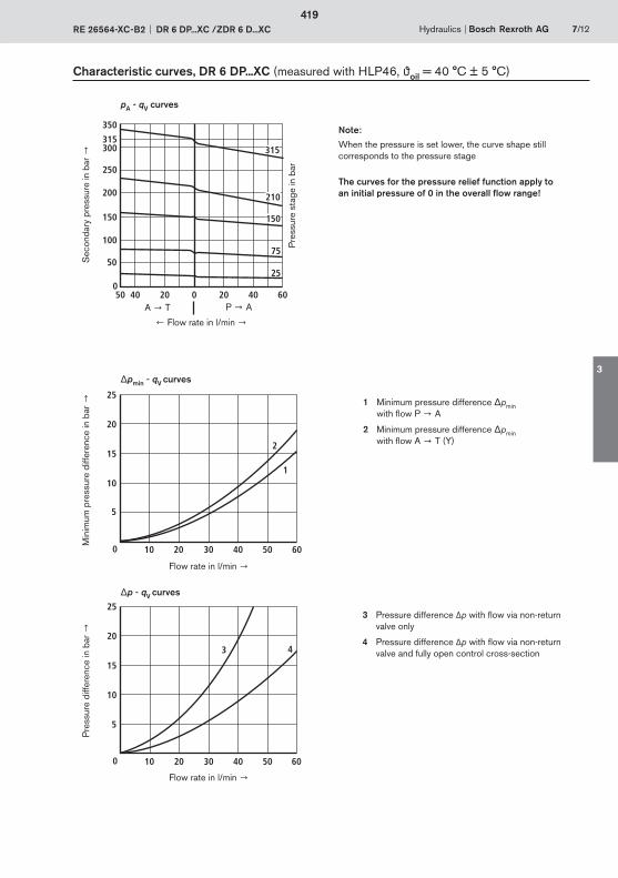
040
50
50 20 0 20 40 60
100
150
200
250
300315
350
25
75
150
210
315
0
5
10 20 30 40 50 60
10
15
20
25
2
1
0
5
10 20 30 40 50 60
10
15
20
25
3 4
Hydraulics Bosch Rexroth AGRE 26564-XC-B2 DR 6 DP...XC /ZDR 6 D...XC 7/12
Characteristic curves, DR 6 DP...XC (measured with HLP46, oil = 40 °C ± 5 °C)
pA - qV curves
pmin - qV curves
p - qV curves
Note:
When the pressure is set lower, the curve shape still corresponds to the pressure stage
The curves for the pressure relief function apply to an initial pressure of 0 in the overall flow range!
Flow rate in l/min
P AA T
Sec
onda
ry p
ress
ure
in b
ar
Min
imum
pre
ssur
e di
ffere
nce
in b
ar
Pre
ssur
e di
ffere
nce
in b
ar
Flow rate in l/min
Flow rate in l/min
1 Minimum pressure difference pmin with flow P A
2 Minimum pressure difference pminwith flow A T (Y)
3 Pressure difference Δp with flow via non-return valve only
4 Pressure difference Δp with flow via non-return valve and fully open control cross-section
Pre
ssur
e st
age
in b
ar
419
3
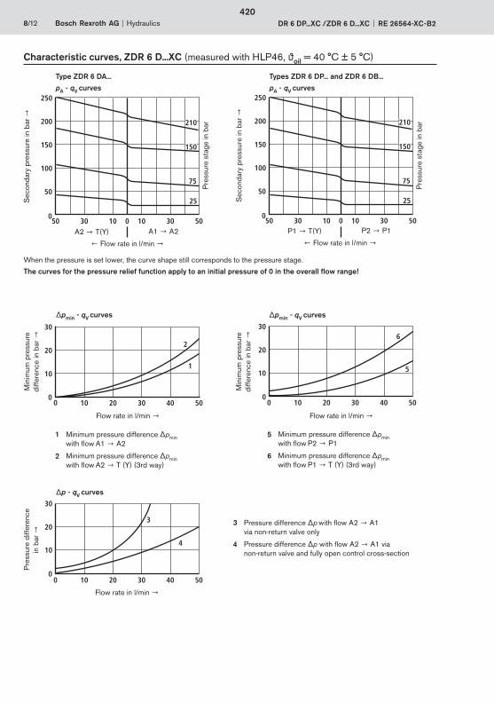
500
30 10 10 30 500
50
100
150
200
250
25
75
210
150
500
30 10 10 30 500
50
100
150
200
250
25
75
210
150
00
10 20 30 40 50
10
20
30
1
2
00
10 20 30 40 50
10
20
30
5
6
00
10 20 30 40 50
10
20
30
4
3
8/12 Bosch Rexroth AG Hydraulics DR 6 DP...XC /ZDR 6 D...XC RE 26564-XC-B2
Characteristic curves, ZDR 6 D...XC (measured with HLP46, oil = 40 °C ± 5 °C)
Type ZDR 6 DA...
pA - qV curves
When the pressure is set lower, the curve shape still corresponds to the pressure stage.
The curves for the pressure relief function apply to an initial pressure of 0 in the overall flow range!
Sec
onda
ry p
ress
ure
in b
ar
1 Minimum pressure difference pmin with flow A1 A2
2 Minimum pressure difference pmin with flow A2 T (Y) (3rd way)
3 Pressure difference p with flow A2 A1via non-return valve only
4 Pressure difference p with flow A2 A1 via non-return valve and fully open control cross-section
Types ZDR 6 DP... and ZDR 6 DB...
pA - qV curves
Flow rate in l/min
A1 A2A2 T(Y) Flow rate in l/min
P2 P1P1 T(Y)
Pre
ssur
e st
age
in b
ar
Pre
ssur
e st
age
in b
ar
5 Minimum pressure difference pmin with flow P2 P1
6 Minimum pressure difference pmin with flow P1 T (Y) (3rd way)
pmin - qV curves
p - qV curves
pmin - qV curves
Min
imum
pre
ssur
e di
ffere
nce
in b
ar
Flow rate in l/min
Min
imum
pre
ssur
e di
ffere
nce
in b
ar
Flow rate in l/min
Pre
ssur
e di
ffere
nce
in b
ar
Flow rate in l/min
Sec
onda
ry p
ress
ure
in b
ar
420
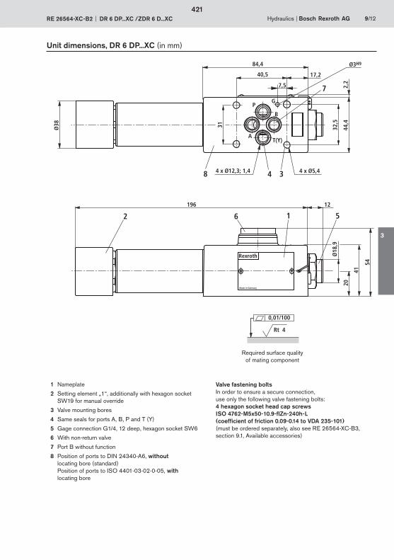
Made in Germany
Rexroth
4 38
7
2 16
32,5
44,4
84,4
40,5 17,2
31
196 12
20
41
Ø18
,9
P
AT(Y)
B
Ø38
5
4 x Ø12,3; 1,4 4 x Ø5,4
54
G
2,27,5
Ø3H9
Hydraulics Bosch Rexroth AGRE 26564-XC-B2 DR 6 DP...XC /ZDR 6 D...XC 9/12
Unit dimensions, DR 6 DP...XC (in mm)
1 Nameplate
2 Setting element „1“, additionally with hexagon socket SW19 for manual override
3 Valve mounting bores
4 Same seals for ports A, B, P and T (Y)
5 Gage connection G1/4, 12 deep, hexagon socket SW6
6 With non-return valve
7 Port B without function
8 Position of ports to DIN 24340-A6, without locating bore (standard)Position of ports to ISO 4401-03-02-0-05, with locating bore
Valve fastening boltsIn order to ensure a secure connection, use only the following valve fastening bolts:4 hexagon socket head cap screws ISO 4762-M5x50-10.9-flZn-240h-L (coefficient of friction 0.09-0.14 to VDA 235-101)(must be ordered separately, also see RE 26564-XC-B3, section 9.1, Available accessories)
Required surface quality of mating component
Rt 4
0,01/100
421
3
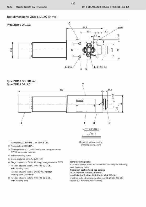
4 x Ø12,3; 1,4
20
40
Ø18
,9Made in Germany
Rexroth
T(Y)A
P
B
4 x Ø5,4
7,5
G
2,2
Ø3H9
Ø38 4632,5
11,1197
2
3 8
7
1 6
31
40,5 13,3
84,5
4 5
10/12 Bosch Rexroth AG Hydraulics DR 6 DP...XC /ZDR 6 D...XC RE 26564-XC-B2
1 Nameplate, ZDR 6 DB… or ZDR 6 DP...
2 Nameplate, ZDR 6 DA...
3 Setting element “1“, additionally with hexagon socket SW19 for manual override
4 Valve mounting bores
5 Same seals for ports A, B, P, T (Y)
6 Gage connection G1/4, 12 deep, hexagon socket SW6
7 Position of ports to ISO 4401-03-02-0-05, with locating bore
Position of ports to DIN 24340-A6, without locating bore (standard)
8 Position of ports to ISO 4401-03-02-0-05, with locating bore
Valve fastening boltsIn order to ensure a secure connection, use only the following valve fastening bolts:4 hexagon socket head cap screws ISO 4762-M5x...-10.9-flZn-240h-L (coefficient of friction 0.09-0.14 to VDA 235-101) (must be ordered separately, also see RE 26564-XC-B3,section 9.1, Available Accessories)
Unit dimensions, ZDR 6 D...XC (in mm)
Type ZDR 6 DA...XC
Type ZDR 6 DB...XC andType ZDR 6 DP...XC
Required surface quality of mating component
Rt 4
0,01/100
422

Hydraulics Bosch Rexroth AGRE 26564-XC-B2 DR 6 DP...XC /ZDR 6 D...XC 11/12
Notes
423
3

Bosch Rexroth AGHydraulicsZum Eisengießer 197816 Lohr am Main, GermanyTelefon +49 (0) 93 52 / 18-0Telefax +49 (0) 93 52 / 18-23 [email protected]
12/12 Bosch Rexroth AG Hydraulics DR 6 DP...XC /ZDR 6 D...XC RE 26564-XC-B2
© This document, as well as the data, specifications and other information set forth in it, are the exclusive property of Bosch Rexroth AG. It may not be reproduced or given to third parties without its consent.The data specified above only serve to describe the product. No state-ments concerning a certain condition or suitability for a certain application can be derived from our information. The information given does not release the user from the obligation of own judgment and verification. It must be remembered that our products are subject to a natural process of wear and aging.
Notes
424
1/12
RE 25802-XC-B2/01.07
Information on explosion protection:
Range of application in accordance with the Explosion Protection Directive and type of protection
– Range of application as per Directive RL 94/9/EG IM2, II2G, II2D
– Type of protection of valve: c (EN 13463-5:2001-01)
ATEX units For potentially explosive atmospheres Part II Technical Data Sheet
What you need to know about these Operating Instructions
These Operating Instructions apply to the explosion-proof version of Rexroth valves, and consist of the following three parts:
Part I General Information RE 07010-X-B1 Part II Technical Data Sheet RE 25802-XC-B2 Part III Product-specific Instructions RE 25802-XC-B3
You can find further information on the correct handling of Rexroth hydraulic products in our publication “General Product Information for Hydraulic Products”, RE 07008.
Mat. No. R901155669
TB0107
Pressure relief valve, pilot operated
Type DB...5X/...XC
Nominal sizes (NG) 10, 20, 30Unit series 5XMaximum operating pressure 350 bar
425
2/12 Bosch Rexroth AG Hydraulics DB...5X/...XC RE 25802-XC-B2
Overview of Contents
Contents Page
Features 2
Ordering data and scope of delivery 3
Function, sectional diagram, symbols 4
Technical data 5
Information on explosion protection 5
Characteristic curves 6, 7
Unit dimensions 8…10
Solenoid-operated relief 11, 12
Features
– For subplate mounting, mounting hole configuration to:ISO 6264-AR-06-2-A (NG10), ISO 6264-AS-08-2-A (NG20), ISO 6264-AT-10-2-A (NG30)
– For threaded connection
– Type of adjustment: rotary knob
– 5 pressure stages
– Subplates (see page 10)
Note:By adding an additional type 3WE 6… spool-type directional control valve, you can expand the valve in such a way that it can feature solenoid-operated relief (see pages 11 and 12).
426
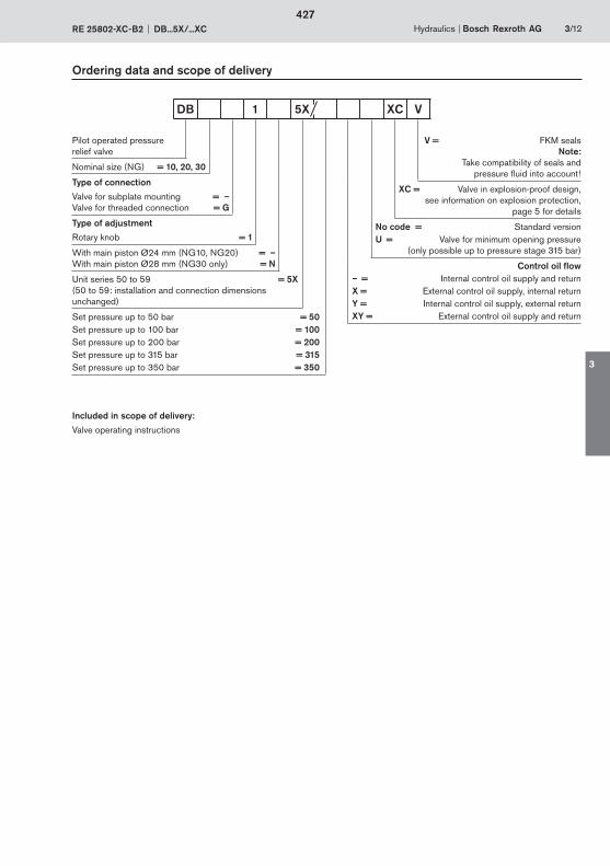
Hydraulics Bosch Rexroth AGRE 25802-XC-B2 DB...5X/...XC 3/12
Ordering data and scope of delivery
Pilot operated pressure relief valve
Nominal size (NG) = 10, 20, 30
Type of connection
Valve for subplate mounting = –Valve for threaded connection = G
Type of adjustment
Rotary knob = 1
With main piston Ø24 mm (NG10, NG20) = –With main piston Ø28 mm (NG30 only) = N
Unit series 50 to 59 = 5X(50 to 59: installation and connection dimensions unchanged)
Set pressure up to 50 bar = 50Set pressure up to 100 bar = 100Set pressure up to 200 bar = 200Set pressure up to 315 bar = 315Set pressure up to 350 bar = 350
V = FKM sealsNote:
Take compatibility of seals and pressure fluid into account !
XC = Valve in explosion-proof design,see information on explosion protection,
page 5 for details
No code = Standard versionU = Valve for minimum opening pressure
(only possible up to pressure stage 315 bar)
Control oil flow– = Internal control oil supply and returnX = External control oil supply, internal returnY = Internal control oil supply, external returnXY = External control oil supply and return
DB 1 5X XC V
Included in scope of delivery:
Valve operating instructions
427
3
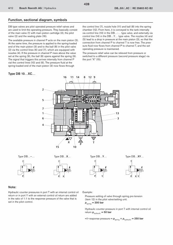
PTX
11 14 8 12 9
2
5
7
1
6
4
15 10
13
3
16
4/12 Bosch Rexroth AG Hydraulics DB...5X/...XC RE 25802-XC-B2
Function, sectional diagram, symbols
Type DB 10…XC…
DB type valves are pilot operated pressure relief valves and are used to limit the operating pressure. They basically consist of the main valve (1) with main piston cartridge (3), the pilot valve (2) and the sealing plate (16).
The available pressure in channel P acts on the main piston (3). At the same time, the pressure is applied to the spring-loaded end of the main piston (3) and to the ball (8) in the pilot valve (2) via the control lines (6) and (7), which are equipped with nozzles (4). If the pressure in channel P rises above the value set at the spring (9), the ball (8) opens against the spring (9). The signal that triggers this arrives internally from channel P vial the control lines (10) and (6). The pressure fluid at the spring-loaded end of the main piston (3) now flows through
the control line (7), nozzle hole (11) and ball (8) into the spring chamber (12). From here, it is conveyed to the tank internally via control line (13) in the DB…-… type valve, and externally via control line (14) in the DB…Y… type valve. The nozzles (4) and (5) lead to a drop in pressure at the main piston (3), so that the connection from channel P to channel T is now free. The pres-sure fluid now flows from channel P to channel T, and the set operating pressure is maintained.
The pressure relief valve can be relieved from pressure or switched to a different pressure (second pressure stage) via the port “X” (15).
Type DB…–… Type DB…X… Type DB…Y… Type DB…XY…
T
P X
T
P Y
T
P YX
T
P
Note:
Hydraulic counter pressures in port T with an internal control oil return or in port Y with an external control oil return are added in the ratio of 1:1 to the response pressure of the valve that is set in the pilot control.
Example:
Pressure setting of valve through spring pre-tension (item 12) in the pilot valve/setting unit.
pspring = 200 bar
Hydraulic counter pressure in port T with internal control oil return phydraulic = 50 bar
=> response pressure = pspring + phydraulic = 250 bar
428
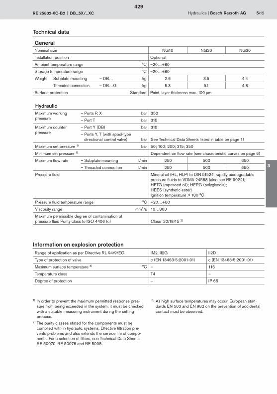
Hydraulics Bosch Rexroth AGRE 25802-XC-B2 DB...5X/...XC 5/12
Technical data
Range of application as per Directive RL 94/9/EG IM2, II2G II2D
Type of protection of valve c (EN 13463-5:2001-01) c (EN 13463-5:2001-01)
Maximum surface temperature 3) °C – 115
Temperature class T4 –
Degree of protection – IP 65
Information on explosion protection
1) In order to prevent the maximum permitted response pres-sure from being exceeded in the system, it must be checked with a suitable measuring instrument during the setting process.
2) The purity classes stated for the components must be complied with in hydraulic systems. Effective filtration pre-
vents problems and also extends the service life of compo-nents. For a selection of filters, see Technical Data Sheets RE 50070, RE 50076 and RE 5008.
GeneralNominal size NG10 NG20 NG30
Installation position Optional
Ambient temperature range °C –20…+80
Storage temperature range °C –20…+80
Weight Subplate mounting – DB… kg 2.6 3.5 4.4
Threaded connection – DB…G kg 5.3 5.1 4.8
Surface protection Standard Paint, layer thickness max. 100 μm
HydraulicMaximum working pressure
– Ports P, X bar 350
– Port T bar 315
Maximum counter pressure
– Port Y (DB) bar 315
– Ports Y, T (with spool-type directional control valve) bar See Technical Data Sheets listed in table on page 11
Maximum set pressure 1) bar 50; 100; 200; 315; 350
Minimum set pressure 1) Dependent on flow rate (see characteristic curves on page 6)
Maximum flow rate – Subplate mounting l/min 250 500 650
– Threaded connection l/min 250 500 650
Pressure fluid Mineral oil (HL, HLP) to DIN 51524, rapidly biodegradable pressure fluids to VDMA 24568 (also see RE 90221), HETG (rapeseed oil); HEPG (polyglycols); HEES (synthetic ester)Ignition temperature > 180 °C
Pressure fluid temperature range °C –20…+80
Viscosity range mm2/s 10…800
Maximum permissible degree of contamination of pressure fluid Purity class to ISO 4406 (c) Class 20/18/15 2)
3) As high surface temperatures may occur, European stan-dards EN 563 and EN 982 on the prevention of accidental contact must be observed.
429
3
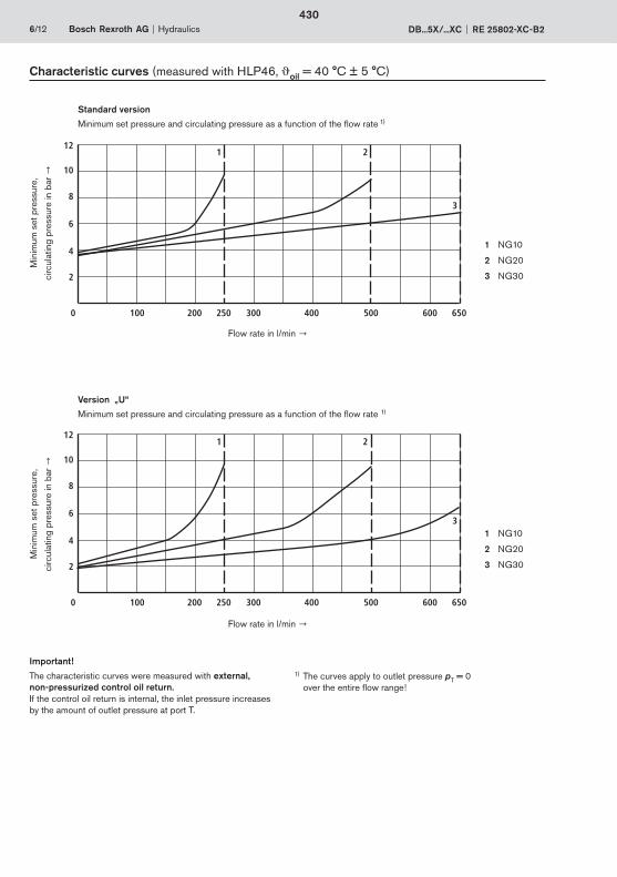
12
10
8
6
4
2
0 100 200 250 300 400 500 600 650
1 2
3
12
10
8
6
4
2
0 100 200 250 300 400 500 600 650
1 2
3
6/12 Bosch Rexroth AG Hydraulics DB...5X/...XC RE 25802-XC-B2
Characteristic curves (measured with HLP46, oil = 40 °C ± 5 °C)
Important!
The characteristic curves were measured with external, non-pressurized control oil return. If the control oil return is internal, the inlet pressure increases by the amount of outlet pressure at port T.
Min
imum
set
pre
ssur
e,
circ
ulat
ing
pres
sure
in b
ar
Flow rate in l/min
Standard version
Minimum set pressure and circulating pressure as a function of the flow rate 1)
1 NG10
2 NG20
3 NG30
Min
imum
set
pre
ssur
e,
circ
ulat
ing
pres
sure
in b
ar
Flow rate in l/min
Version „U“
Minimum set pressure and circulating pressure as a function of the flow rate 1)
1) The curves apply to outlet pressure pT = 0 over the entire flow range!
1 NG10
2 NG20
3 NG30
430

Hydraulics Bosch Rexroth AGRE 25802-XC-B2 DB...5X/...XC 7/12
Characteristic curves (measured with HLP46, oil = 40 °C ± 5 °C)
400
350
315300
250
200
150
100
50
0 100 200 250 300 400 500 600 650
1 2 3
2,0
1,4
1,0
0,8
0,4
0 100 200 250 300 400 500 600 650
1 2 3
0,2
0,6
1,2
1,6
1,8
Inle
t pre
ssur
e in
bar
1 NG10
2 NG20
3 NG30
Important:
The characteristic curves were measured with external, non-pressurized control oil return. If the control oil return is internal, the inlet pressure increases by the amount of outlet pressure at port T.
Flow rate in l/min
Inlet pressure as a function of the flow rate
Con
trol
oil
flow
rate
in l/
min
Flow rate in l/min
Control oil flow rate
1 NG10
2 NG20
3 NG30
431
3
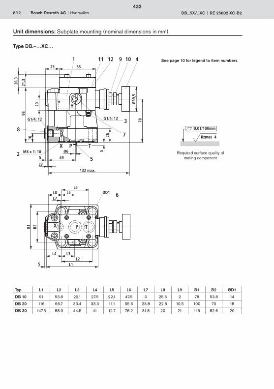
98
16
G1/4; 12 G1/4; 12
Ø39
,578
265
49
Ø6M8 x 1; 105
L9
132 max.
X P T
Y
3
7
2
21,3
26,3
6525
5
8
20
1 11 9 10 412
X
ØD1L6
L5L8L7
B1 B2
L4 L3
5 L1L2
P T
6
8/12 Bosch Rexroth AG Hydraulics DB...5X/...XC RE 25802-XC-B2
Required surface quality of mating component
0,01/100mm
Rzmax 4
Type DB.–…XC…
Unit dimensions: Subplate mounting (nominal dimensions in mm)
Typ L1 L2 L3 L4 L5 L6 L7 L8 L9 B1 B2 ØD1
DB 10 91 53.8 22.1 27.5 22.1 47.5 0 25.5 2 78 53.8 14
DB 20 116 66.7 33.4 33.3 11.1 55.6 23.8 22.8 10.5 100 70 18
DB 30 147.5 88.9 44.5 41 12.7 76.2 31.8 20 21 115 82.6 20
See page 10 for legend to item numbers
432
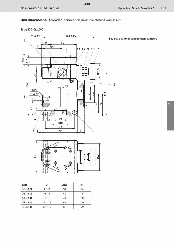
132 max.
495
G1/4; 12
134
Ø25
G1/4; 12
5,5
44
T11 11 D1
ØD2
72
904 17
T1 1
D1
ØD
2
47 56
114
Ø39
,5
80 Ø72
3
2 6
Y
P
T
X
21,3
26,3
6525
7
20
1
11 9 10 4
8
12
Hydraulics Bosch Rexroth AGRE 25802-XC-B2 DB...5X/...XC 9/12
Unit dimensions: Threaded connection (nominal dimensions in mm)
Type D1 ØD2 T1
DB 10 G G1/2 34 14
DB 15 G G3/4 42 16
DB 20 G G1 47 18
DB 25 G G1 1/4 58 20
DB 30 G G1 1/2 65 22
See page 10 for legend to item numbers
Type DB.G…XC…
433
3
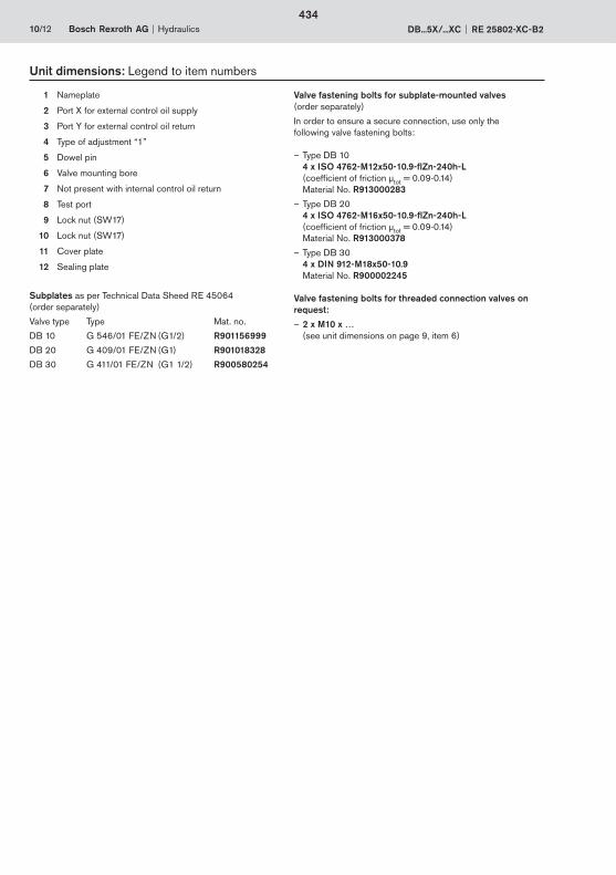
10/12 Bosch Rexroth AG Hydraulics DB...5X/...XC RE 25802-XC-B2
1 Nameplate
2 Port X for external control oil supply
3 Port Y for external control oil return
4 Type of adjustment “1”
5 Dowel pin
6 Valve mounting bore
7 Not present with internal control oil return
8 Test port
9 Lock nut (SW17)
10 Lock nut (SW17)
11 Cover plate
12 Sealing plate
Subplates as per Technical Data Sheed RE 45064(order separately)
Valve type Type Mat. no.
DB 10 G 546/01 FE/ZN (G1/2) R901156999
DB 20 G 409/01 FE/ZN (G1) R901018328
DB 30 G 411/01 FE/ZN (G1 1/2) R900580254
Valve fastening bolts for subplate-mounted valves (order separately)
In order to ensure a secure connection, use only the following valve fastening bolts:
– Type DB 104 x ISO 4762-M12x50-10.9-flZn-240h-L(coefficient of friction μtot = 0.09-0.14)Material No. R913000283
– Type DB 204 x ISO 4762-M16x50-10.9-flZn-240h-L(coefficient of friction μtot = 0.09-0.14)Material No. R913000378
– Type DB 304 x DIN 912-M18x50-10.9Material No. R900002245
Valve fastening bolts for threaded connection valves on request:
– 2 x M10 x … (see unit dimensions on page 9, item 6)
Unit dimensions: Legend to item numbers
434

Y
Hydraulics Bosch Rexroth AGRE 25802-XC-B2 DB...5X/...XC 11/12
Solenoid-operated relief
With the addition of a type 3WE 6… spool-type directional control valve, the valve can be converted in such a way that it is capable of being electrically switched to non-pressurized circulation (main piston relieved of pressure).
Before adding a 3WE 6… spool-type directional control valve to a DB…5X/…XC pilot operated pressure relief valve, check whether the category and safety class resulting from this com-bination still satisfy the requirements of the potentially explosive atmosphere in which the valve is to be used.
The spool-type directional control valves for the conversion and the resulting categories and safety classes are set out in the table below.
The spool-type directional control valve determines the category to Directive 94/9/EG :
Important notes:
– The relief function with directional control valve must not be used for safety functions!
– During assembly, please note the operating instructions that are supplied with the spool-type directional control valves.
– Modification or conversion of valves without the use of the operating instructions is not permitted.
– Before assembly, identify all parts by means of their nameplates.
Example:
Addition of a 3WE 6…6X/…XE spool-type directional control valve
The assembly of the directional control valve (removal of sealing plate) is described in RE 25802-XC-B3, section 3.4.
1) When selecting a valve, please also note the possible switching versions on page 12.
Spool-type directional control valve
Category to 94/9/EG
Technical Data Sheet
3WE 6…5X/…XH IM2; II2G RE 23177-XH-B2
3WE 6…6X/…XD IM2; II2G RE 23178-XD-B2
3WE 6…6X/…XE II2G RE 23178-XE-B2
3WE 6…6X/…XN II3G; II3D RE 23178-XN-B2
Example:
DB…5X/…XC plus 3WE 6…6X/…XN 1) results in suitability for use in category II3G; II3D
435
3
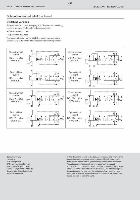
Bosch Rexroth AGHydraulicsZum Eisengießer 197816 Lohr am Main, GermanyTelefon +49 (0) 93 52 / 18-0Telefax +49 (0) 93 52 / 18-23 [email protected]
12/12 Bosch Rexroth AG Hydraulics DB...5X/...XC RE 25802-XC-B2
© This document, as well as the data, specifications and other informa-tion set forth in it, are the exclusive property of Bosch Rexroth AG. It may not be reproduced or given to third parties without its consent.The data specified above only serve to describe the product. No statements concerning a certain condition or suitability for a certain application can be derived from our information. The information given does not release the user from the obligation of own judgment and verification. It must be remembered that our products are subject to a natural process of wear and aging.
Solenoid-operated relief (continued)
Switching versionsFor each type of control oil supply of a DB valve, two switching versions are possible for solenoid-operated relief:
– Closed without current
– Open without current
The choice of piston for the 3WE 6… spool-type directional control valve is determined by the required switching version.
Closed without current
DB…–… plus 3WE 6 A…
T
P
A B
P T
a b
T
P
A B
P T
a b
Closed without current
DB…X… plus 3WE 6 A…
T
P
A B
P T
a b
X
T
P
A B
P T
a b
X
Open without current
DB…–… plus 3WE 6 B…
Open without current
DB…X… plus 3WE 6 B…
Closed without current
DB…Y… plus 3WE 6 A…
T
P
A B
P T
a b
Y
T
P
A B
P T
a b
Y
Closed without current
DB…XY… plus 3WE 6 A…
T
P
A B
P T
a b
X Y
T
P
A B
P T
a b
X Y
Open without current
DB…Y… plus 3WE 6 B…
Open without current
DB…XY… plus 3WE 6 B…
436
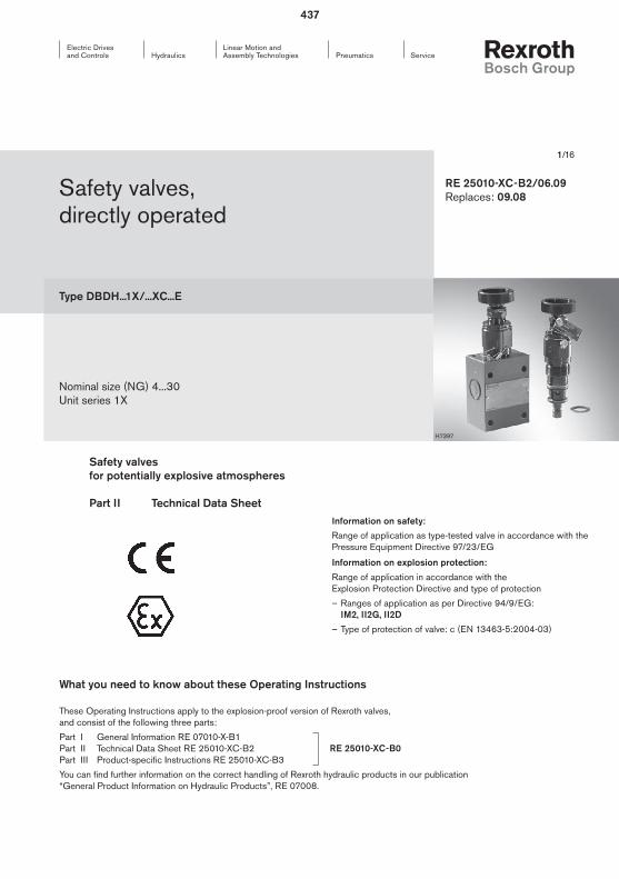
1/16
Safety valves, directly operated
Type DBDH...1X/...XC...E
Nominal size (NG) 4...30Unit series 1X
RE 25010-XC-B2/06.09Replaces: 09.08
Information on safety:
Range of application as type-tested valve in accordance with the Pressure Equipment Directive 97/23/EG
Information on explosion protection:
Range of application in accordance with the Explosion Protection Directive and type of protection
– Ranges of application as per Directive 94/9/EG: IM2, II2G, II2D
– Type of protection of valve: c (EN 13463-5:2004-03)
Safety valves for potentially explosive atmospheres Part II Technical Data Sheet
What you need to know about these Operating Instructions
These Operating Instructions apply to the explosion-proof version of Rexroth valves, and consist of the following three parts:
Part I General Information RE 07010-X-B1 Part II Technical Data Sheet RE 25010-XC-B2 Part III Product-specific Instructions RE 25010-XC-B3
You can find further information on the correct handling of Rexroth hydraulic products in our publication “General Product Information on Hydraulic Products”, RE 07008.
RE 25010-XC-B0
H7397
437

2/16 Bosch Rexroth AG Hydraulics DBDH...1X/...XC...E RE 25010-XC-B2
Overview of Contents
Contents Page
Features 2
Ordering data and scope of delivery 3
Component identification mark 3
Function, sectional diagram, symbol 4
Technical data 5
Information on explosion protection 5
Characteristic curves for maximum permitted flow rate 6
Important information for operation in accordance with the Pressure Equipment Directive 97/23/EG 7
Characteristic curves with back pressure in the flow line 8 ... 11
Unit dimensions 12 ... 16
Features
– As ATEX units in accordance with Directive 94/9/EG for ranges of application: IM2, II2G, II2D
– As type-tested safety valves in accordance with Pressure Equipment Directive 97/23/EG
– As screw-in valve (cartridge)
– For threaded connection
– For sub plate mounting
– Adjustment with hand wheel
438
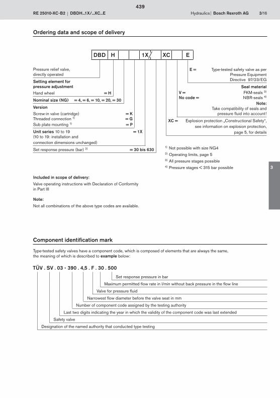
Hydraulics Bosch Rexroth AGRE 25010-XC-B2 DBDH...1X/...XC...E 3/16
Ordering data and scope of delivery
Component identification mark
Type-tested safety valves have a component code, which is composed of elements that are always the same, the meaning of which is described to example below:
TÜV . SV . 03 - 390 . 4,5 . F . 30 . 500
Set response pressure in bar
Maximum permitted flow rate in l/min without back pressure in the flow line
Valve for pressure fluid
Narrowest flow diameter before the valve seat in mm
Number of component code assigned by the testing authority
Last two digits indicating the year in which the validity of the component code was last extended
Safety valve
Designation of the named authority that conducted type testing
Pressure relief valve, directly operated
Setting element forpressure adjustmentHand wheel = H
Nominal size (NG) = 4, = 6, = 10, = 20, = 30
VersionScrew-in valve (cartridge) = KThreaded connection 1) = GSub plate mounting 1) = P
Unit series 10 to 19 = 1X(10 to 19: installation andconnection dimensions unchanged)
Set response pressure (bar) 2) = 30 bis 630
E = Type-tested safety valve as per Pressure Equipment Directive 97/23/EG
Seal materialV = FKM-seals 3)
No code = NBR-seals 4)
Note:Take compatibility of seals and
pressure fluid into account !
XC = Explosion protection „Constructional Safety“,see information on explosion protection,
page 5, for details
DBD H 1X XC E
1) Not possible with size NG42) Operating limits, page 53) All pressure stages possible4) Pressure stages < 315 bar possible
Included in scope of delivery:
Valve operating instructions with Declaration of Conformity in Part III
Note:
Not all combinations of the above type codes are available.
439
3
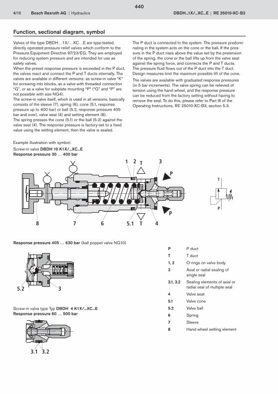
P
T
4/16 Bosch Rexroth AG Hydraulics DBDH...1X/...XC...E RE 25010-XC-B2
Function, sectional diagram, symbol
Valves of the type DBDH…1X/…XC…E are type-tested, directly operated pressure relief valves which conform to the Pressure Equipment Directive 97/23/EG. They are employed for reducing system pressure and are intended for use as safety valves. When the preset response pressure is exceeded in the P duct, the valves react and connect the P and T ducts internally. The valves are available in different versions: as screw-in valve “K” for screwing into blocks, as a valve with threaded connection “G”, or as a valve for subplate mounting “P” (“G” and “P” are not possible with size NG4). The screw-in valve itself, which is used in all versions, basically consists of the sleeve (7), spring (6), cone (5.1, response pressure up to 400 bar) or ball (5.2, response pressure 405 bar and over), valve seat (4) and setting element (8).The spring presses the cone (5.1) or the ball (5.2) against the valve seat (4). The response pressure is factory-set to a fixed value using the setting element, then the valve is sealed.
The P duct is connected to the system. The pressure predomi-nating in the system acts on the cone or the ball. If the pres-sure in the P duct rises above the value set by the pretension of the spring, the cone or the ball lifts up from the valve seat against the spring force, and connects the P and T ducts. The pressure fluid flows out of the P duct into the T duct. Design measures limit the maximum possible lift of the cone.
The valves are available with graduated response pressures (in 5 bar increments). The valve spring can be relieved of tension using the hand wheel, and the response pressure can be reduced from the factory setting without having to remove the seal. To do this, please refer to Part III of the Operating Instructions, RE 25010-XC-B3, section 5.3.
Example illustration with symbol:
Screw-in valve DBDH 10 K1X/...XC...EResponse pressure 30 … 400 bar
Response pressure 405 … 630 bar (ball poppet valve NG10)
Screw-in valve type Typ DBDH 4 K1X/...XC...EResponse pressure 60 … 500 bar
P P duct
T T duct
1, 2 O-rings on valve body
3 Axial or radial sealing of single seal
3.1, 3.2 Sealing elements of axial or radial seal of multiple seal
4 Valve seat
5.1 Valve cone
5.2 Valve ball
6 Spring
7 Sleeve
8 Hand wheel setting element
440
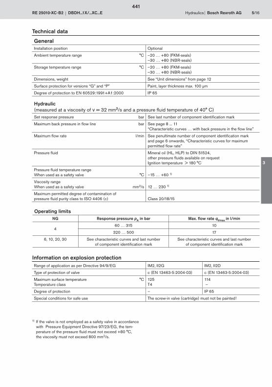
Hydraulics Bosch Rexroth AGRE 25010-XC-B2 DBDH...1X/...XC...E 5/16
Technical data
GeneralInstallation position Optional
Ambient temperature range °C –20 … +80 (FKM-seals)–30 … +80 (NBR-seals)
Storage temperature range °C –20 … +80 (FKM-seals)–30 … +80 (NBR-seals)
Dimensions, weight See “Unit dimensions” from page 12
Surface protection for versions “G” and “P” Paint, layer thickness max. 100 μm
Degree of protection to EN 60529:1991+A1:2000 IP 65
Hydraulic (measured at a viscosity of = 32 mm2/s and a pressure fluid temperature of 40° C)Set response pressure bar See last number of component identification mark
Maximum back pressure in flow line bar See page 8 ... 11“Characteristic curves … with back pressure in the flow line”
Maximum flow rate l/min See penultimate number of component identification mark and page 6 onwards, “Characteristic curves for maximum permitted flow rate”
Pressure fluid Mineral oil (HL, HLP) to DIN 51524,other pressure fluids available on request Ignition temperature > 180 °C
Pressure fluid temperature rangeWhen used as a safety valve °C –15 … +60 1)
Viscosity range When used as a safety valve mm2/s 12 … 230 1)
Maximum permitted degree of contamination of pressure fluid purity class to ISO 4406 (c) Class 20/18/15
Range of application as per Directive 94/9/EG IM2, II2G IM2, II2D
Type of protection of valve c (EN 13463-5:2004-03) c (EN 13463-5:2004-03)
Maximum surface temperatureTemperature class
°C 125T4
114 –
Degree of protection – IP 65
Special conditions for safe use The screw-in valve (cartridge) must not be painted!
Information on explosion protection
1) If the valve is not employed as a safety valve in accordance with Pressure Equipment Directive 97/23/EG, the tem-perature of the pressure fluid must not exceed +80 °C,
the viscosity must not exceed 800 mm2/s.
Operating limitsNG Response pressure pA in bar Max. flow rate qVmax in l/min
460 … 315 10
320 … 500 17
6, 10, 20, 30 See characteristic curves and last number of component identification mark
See characteristic curves and last number of component identification mark
441
3
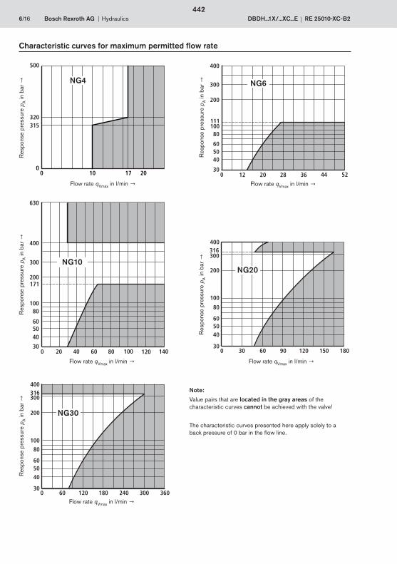
0
500
320315
170 10 20
400
300
405060
80
200
300 20 40 60 80 100 120
100
140
171
630
400
300
405060
80
200
300 12 20 28 36 44 52
100111
400
200
405060
80
100
300 30 60 90 120 150 180
300316
400
200
405060
80
100
300 60 120 180 240 300 360
300316
6/16 Bosch Rexroth AG Hydraulics DBDH...1X/...XC...E RE 25010-XC-B2
Characteristic curves for maximum permitted flow rate
Flow rate qVmax in l/min Flow rate qVmax in l/min
Flow rate qVmax in l/min Flow rate qVmax in l/min
Flow rate qVmax in l/min
Note:
Value pairs that are located in the gray areas of the characteristic curves cannot be achieved with the valve!
The characteristic curves presented here apply solely to a back pressure of 0 bar in the flow line.
Res
pons
e pr
essu
re p
A in
bar
R
espo
nse
pres
sure
pA in
bar
Res
pons
e pr
essu
re p
A in
bar
R
espo
nse
pres
sure
pA in
bar
Res
pons
e pr
essu
re p
A in
bar
NG4 NG6
NG10NG20
NG30
442
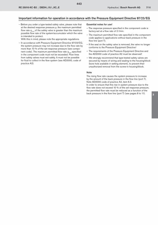
Hydraulics Bosch Rexroth AGRE 25010-XC-B2 DBDH...1X/...XC...E 7/16
Important information for operation in accordance with the Pressure Equipment Directive 97/23/EG
– Before you order a type-tested safety valve, please note that at the desired response pressure p, the maximum permitted flow rate qVmax of the safety valve is greater than the maximum possible flow rate of the system/accumulator which the valve is intended to protect.
With this in mind, please note the appropriate regulations.
– In accordance with Pressure Equipment Directive 97/23/EG, the system pressure may not increase due to the flow rate by more than 10 % of the set response pressure (see compo-nent code). The maximum permitted flow rate qVmax specified in the component code must not be exceeded. Flow lines from safety valves must exit safely. It must not be possible for fluid to collect in the flow system (see AD2000, code of practice A2).
Essential notes for use!
– The response pressure specified in the component code is factory-set at a flow rate of 2 l/min.
– The maximum permitted flow rate specified in the component code applies to applications without back pressure in the flow line (port T).
– If the seal on the safety valve is removed, the valve no longer conforms to the Pressure Equipment Directive !
– The requirements of the Pressure Equipment Directive and the AD2000 code of practice A2 must be observed !
– We strongly recommend that type-tested safety valves are secured by means of wiring and sealing to the housing/block (bore hole available in setting element), to prevent their
unauthorized removal from the screw-in housing/block.
Note
The rising flow rate causes the system pressure to increase by the amount of the back pressure in the flow line (port T). Note AD2000 code of practice A2, item 6.3.In order to ensure that this rise in system pressure due to the flow rate does not exceed 10 % of the set response pressure, the permitted flow rate must be reduced as a function of the back pressure in the flow line (port T) (see pages 8 to 11).
443
3
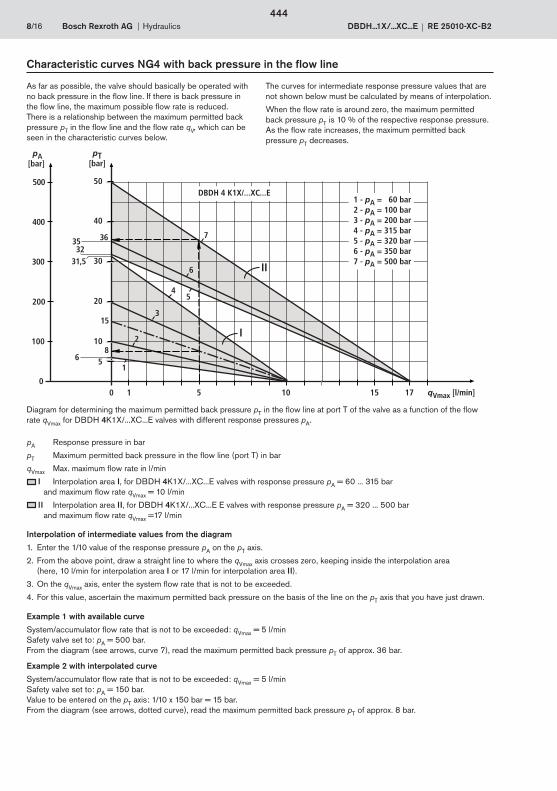
00
68
5
10
20
30
pT[bar]
200
100
pA[bar]
300
40400
50500
1 10
35 36
15
3231,5
155
1
2
3
45
17 qVmax [l/min]
6
7
II
I
DBDH 4 K1X/...XC...E1 - pA = 60 bar2 - pA = 100 bar3 - pA = 200 bar4 - pA = 315 bar5 - pA = 320 bar6 - pA = 350 bar7 - pA = 500 bar
8/16 Bosch Rexroth AG Hydraulics DBDH...1X/...XC...E RE 25010-XC-B2
Characteristic curves NG4 with back pressure in the flow line
As far as possible, the valve should basically be operated with no back pressure in the flow line. If there is back pressure in the flow line, the maximum possible flow rate is reduced. There is a relationship between the maximum permitted back pressure pT in the flow line and the flow rate qV, which can be seen in the characteristic curves below.
The curves for intermediate response pressure values that are not shown below must be calculated by means of interpolation.
When the flow rate is around zero, the maximum permitted back pressure pT is 10 % of the respective response pressure. As the flow rate increases, the maximum permitted back pressure pT decreases.
Diagram for determining the maximum permitted back pressure pT in the flow line at port T of the valve as a function of the flow rate qVmax for DBDH 4K1X/...XC...E valves with different response pressures pA.
pA Response pressure in bar
pT Maximum permitted back pressure in the flow line (port T) in bar
qVmax Max. maximum flow rate in l/min
I Interpolation area I, for DBDH 4K1X/...XC...E valves with response pressure pA = 60 ... 315 bar and maximum flow rate qVmax = 10 l/min II Interpolation area II, for DBDH 4K1X/...XC...E E valves with response pressure pA = 320 ... 500 bar and maximum flow rate qVmax =17 l/min
Example 1 with available curve
System/accumulator flow rate that is not to be exceeded: qVmax = 5 l/min Safety valve set to: pA = 500 bar. From the diagram (see arrows, curve 7), read the maximum permitted back pressure pT of approx. 36 bar.
Example 2 with interpolated curve
System/accumulator flow rate that is not to be exceeded: qVmax = 5 l/min Safety valve set to: pA = 150 bar. Value to be entered on the pT axis: 1/10 x 150 bar = 15 bar.From the diagram (see arrows, dotted curve), read the maximum permitted back pressure pT of approx. 8 bar.
Interpolation of intermediate values from the diagram
1. Enter the 1/10 value of the response pressure pA on the pT axis.
2. From the above point, draw a straight line to where the qVmax axis crosses zero, keeping inside the interpolation area (here, 10 l/min for interpolation area I or 17 l/min for interpolation area II).
3. On the qVmax axis, enter the system flow rate that is not to be exceeded.
4. For this value, ascertain the maximum permitted back pressure on the basis of the line on the pT axis that you have just drawn.
444
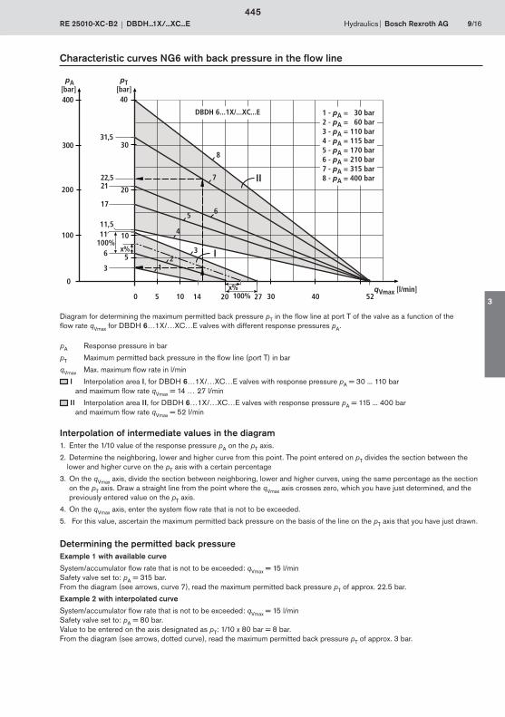
0
2122,5
11,5
17
6 x%
x%100%
5
5
10
20
30
200
100
3
11
300
400
14 27
31,5
40
52
12
3
4
5 6
7
8
30100 20 40
II
I100%
DBDH 6...1X/...XC...E
pT[bar]
pA[bar]
qVmax [l/min]
1 - pA = 30 bar2 - pA = 60 bar3 - pA = 110 bar4 - pA = 115 bar5 - pA = 170 bar6 - pA = 210 bar7 - pA = 315 bar8 - pA = 400 bar
Hydraulics Bosch Rexroth AGRE 25010-XC-B2 DBDH...1X/...XC...E 9/16
Characteristic curves NG6 with back pressure in the flow line
Diagram for determining the maximum permitted back pressure pT in the flow line at port T of the valve as a function of the flow rate qVmax for DBDH 6…1X/…XC…E valves with different response pressures pA.
pA Response pressure in bar
pT Maximum permitted back pressure in the flow line (port T) in bar
qVmax Max. maximum flow rate in l/min
I Interpolation area I, for DBDH 6…1X/…XC…E valves with response pressure pA = 30 ... 110 bar and maximum flow rate qVmax = 14 … 27 l/min
II Interpolation area II, for DBDH 6…1X/…XC…E valves with response pressure pA = 115 ... 400 bar and maximum flow rate qVmax = 52 l/min
Interpolation of intermediate values in the diagram 1. Enter the 1/10 value of the response pressure pA on the pT axis.
2. Determine the neighboring, lower and higher curve from this point. The point entered on pT divides the section between the lower and higher curve on the pT axis with a certain percentage
3. On the qVmax axis, divide the section between neighboring, lower and higher curves, using the same percentage as the section on the pT axis. Draw a straight line from the point where the qVmax axis crosses zero, which you have just determined, and the previously entered value on the pT axis.
4. On the qVmax axis, enter the system flow rate that is not to be exceeded.
5. For this value, ascertain the maximum permitted back pressure on the basis of the line on the pT axis that you have just drawn.
Determining the permitted back pressureExample 1 with available curve
System/accumulator flow rate that is not to be exceeded: qVmax = 15 l/min Safety valve set to: pA = 315 bar. From the diagram (see arrows, curve 7), read the maximum permitted back pressure pT of approx. 22.5 bar.
Example 2 with interpolated curve
System/accumulator flow rate that is not to be exceeded: qVmax = 15 l/min Safety valve set to: pA = 80 bar. Value to be entered on the axis designated as pT: 1/10 x 80 bar = 8 bar. From the diagram (see arrows, dotted curve), read the maximum permitted back pressure pT of approx. 3 bar.
445
3
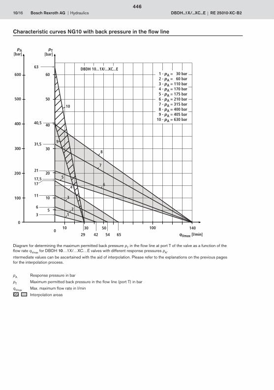
0
0
21
40,5
17
6
pT[bar]
200
100
3
pA[bar]
11
17,5
300
400
31,5
40
10
5
20
30
50
60
12
3
4
10
6
63
500
600
10 50 100
4229
14030
6554
9
5
7
8
qVmax [l/min]
DBDH 10...1X/...XC...E 1 - pA = 30 bar 2 - pA = 60 bar 3 - pA = 110 bar 4 - pA = 170 bar 5 - pA = 175 bar 6 - pA = 210 bar 7 - pA = 315 bar 8 - pA = 400 bar 9 - pA = 405 bar10 - pA = 630 bar
10/16 Bosch Rexroth AG Hydraulics DBDH...1X/...XC...E RE 25010-XC-B2
Characteristic curves NG10 with back pressure in the flow line
pA Response pressure in bar
pT Maximum permitted back pressure in the flow line (port T) in bar
qVmax Max. maximum flow rate in l/min
Interpolation areas
Diagram for determining the maximum permitted back pressure pT in the flow line at port T of the valve as a function of the flow rate qVmax for DBDH 10…1X/…XC…E valves with different response pressures pA.
ntermediate values can be ascertained with the aid of interpolation. Please refer to the explanations on the previous pages for the interpolation process.
446
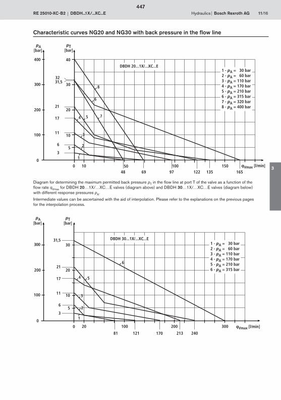
00
21
17
65
10
20
30
200
100
3
11
300
12181
20 100
31,5
200 300
1
2
3
4 5
6
213 240170
1 - pA = 30 bar2 - pA = 60 bar3 - pA = 110 bar4 - pA = 170 bar5 - pA = 210 bar6 - pA = 315 bar
DBDH 30...1X/...XC...E
pT[bar]
pA[bar]
qVmax [l/min]
0
21
17
6
200
100
3
11
300
694810 50
31,5
100 150
1
2
5 7
6
8
13512297 165
400
32
4
3
0
10
5
20
30
40
1 - pA = 30 bar2 - pA = 60 bar3 - pA = 110 bar4 - pA = 170 bar5 - pA = 210 bar6 - pA = 315 bar7 - pA = 320 bar8 - pA = 400 bar
DBDH 20...1X/...XC...E
pT[bar]
pA[bar]
qVmax [l/min]
Hydraulics Bosch Rexroth AGRE 25010-XC-B2 DBDH...1X/...XC...E 11/16
Characteristic curves NG20 and NG30 with back pressure in the flow line
Diagram for determining the maximum permitted back pressure pT in the flow line at port T of the valve as a function of the flow rate qVmax for DBDH 20…1X/…XC…E valves (diagram above) and DBDH 30…1X/…XC…E valves (diagram below) with different response pressures pA.
Intermediate values can be ascertained with the aid of interpolation. Please refer to the explanations on the previous pages for the interpolation process.
447
3

Sichtkontrolle
Pt 16
Pt 1613
,0±0
,56
Pt 1...16
min 10,8
M14x1
max
. 94
R0,2 +0,2
R0,1 +0,1
2
2
0,05
min
. 40
1
4
3
2
5
12/16 Bosch Rexroth AG Hydraulics DBDH...1X/...XC...E RE 25010-XC-B2
Unit dimensions: Screw-in valve NG4 (in mm)
1 Hand wheel setting element
2 Stamped type designation
3 Hexagon, width across flats 17 mm
4 Lock nut, width across flats 17 mm
5 Port T, anywhere on the perimeter
1) Minimum diameter in recess2) All edges of sealing ring insertion taper rounded and free
from burrs3) Fitting depth4) Maximum dimension with response pressure at lowest setting
Visual inspection
Tolerancing: DIN 7167General tolerances: ISO 2768-mk
448
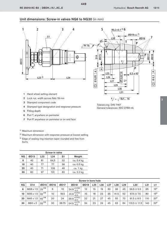
0,02
L31
L24L23 2)
3 41
ØD16ØD19-0,2 1)
L25
L26
L28
L27
L29L30
0,5 x 45°
5 6
7
2
Ø 0
,1A
Ø 0
,05
A
x
x
ØD
17
ØD
18
ØD
15D
14
45°
A
1
S1
ØD
13
= Rz1... 16x
A
Pt 16
R0,2±0,1 3)
T P
P
P
Hydraulics Bosch Rexroth AGRE 25010-XC-B2 DBDH...1X/...XC...E 13/16
Unit dimensions: Screw-in valves NG6 to NG30 (in mm)
Screw-in valve
NG ØD13 L23 L24 S1 Weight
6 40 81 64,5 32 ca. 0.4 kg
10 40 77 77 36 ca. 0.5 kg
20 40 71 106 46 ca. 1 kg
30 80 97 131 60 ca. 2.2 kg
Screw-in bore hole
NG D14 ØD15 ØD16 ØD17 ØD18 ØD19 L25 L26 L27 L28 L29 L30 L31 1
6 M28 x 1.5 25 H9 6 15 24.9 +0.152 12 15 19 30 36 45 56.5 ± 5.5 65 15°–0.2
10 M35 x 1.5 32 H9 10 18.5 31.9 +0.162 15 18 23 35 41.5 52 67.5 ± 7.5 80 15°–0.2
20 M45 x 1.5 40 H9 20 24 39.9 +0.162 22 21 27 45 55 70 91.5 ± 8.5 110 20°–0.2
30 M60 x 2 55 H9 30 38.75 54.9 +0.174 34 23 29 45 63 84 113.5 ± 11.5 140 20°–0.2
1 Hand wheel setting element
2 Lock nut, width across flats 19 mm
3 Stamped component code
4 Stamped type designation and response pressure
5 Fitting depth
6 Port T, anywhere on perimeter
7 Port P, anywhere on perimeter or on end face
1) Maximum dimension2) Maximum dimension with response pressure at lowest setting3) Edge of sealing ring insertion taper rounded and free from
burrs
Tolerancing: DIN 7167General tolerances: ISO 2768-mk
449
3
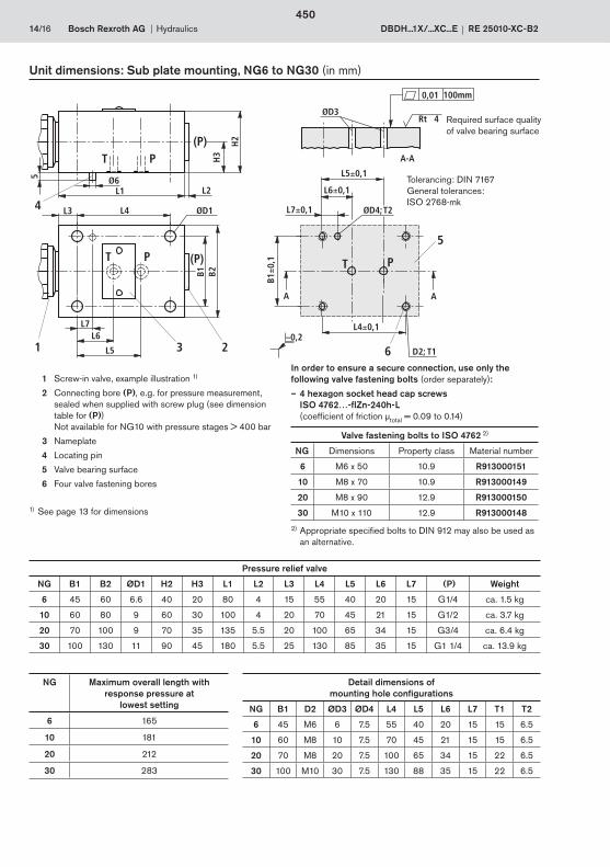
14/16 Bosch Rexroth AG Hydraulics DBDH...1X/...XC...E RE 25010-XC-B2
PT
(P)PT
L1
L4L3
L2
H2
B2B1ØD1
L6
L5
PT
D2; T1
ØD3
5
23 6
L7
Ø65
4H
3
A A
A-A
(P)
ØD4; T2
1
L6±0,1
L7±0,1
L5±0,1
B1±0
,1
L4±0,1
0,01 100mm
Rt 4
Unit dimensions: Sub plate mounting, NG6 to NG30 (in mm)
1 Screw-in valve, example illustration 1)
2 Connecting bore (P), e.g. for pressure measurement, sealed when supplied with screw plug (see dimension table for (P)) Not available for NG10 with pressure stages > 400 bar
3 Nameplate
4 Locating pin
5 Valve bearing surface
6 Four valve fastening bores
Valve fastening bolts to ISO 4762 2)
NG Dimensions Property class Material number
6 M6 x 50 10.9 R913000151
10 M8 x 70 10.9 R913000149
20 M8 x 90 12.9 R913000150
30 M10 x 110 12.9 R913000148
2) Appropriate specified bolts to DIN 912 may also be used as an alternative.
In order to ensure a secure connection, use only the following valve fastening bolts (order separately):
– 4 hexagon socket head cap screws ISO 4762…-flZn-240h-L
(coefficient of friction μtotal = 0.09 to 0.14)
Required surface quality of valve bearing surface
Pressure relief valve
NG B1 B2 ØD1 H2 H3 L1 L2 L3 L4 L5 L6 L7 (P) Weight
6 45 60 6.6 40 20 80 4 15 55 40 20 15 G1/4 ca. 1.5 kg
10 60 80 9 60 30 100 4 20 70 45 21 15 G1/2 ca. 3.7 kg
20 70 100 9 70 35 135 5.5 20 100 65 34 15 G3/4 ca. 6.4 kg
30 100 130 11 90 45 180 5.5 25 130 85 35 15 G1 1/4 ca. 13.9 kg
Detail dimensions of mounting hole configurations
NG B1 D2 ØD3 ØD4 L4 L5 L6 L7 T1 T2
6 45 M6 6 7.5 55 40 20 15 15 6.5
10 60 M8 10 7.5 70 45 21 15 15 6.5
20 70 M8 20 7.5 100 65 34 15 22 6.5
30 100 M10 30 7.5 130 88 35 15 22 6.5
1) See page 13 for dimensions
NG Maximum overall length with response pressure at
lowest setting
6 165
10 181
20 212
30 283
Tolerancing: DIN 7167General tolerances: ISO 2768-mk
450

Hydraulics Bosch Rexroth AGRE 25010-XC-B2 DBDH...1X/...XC...E 15/16
L6
(P)P
T
PT
ØD1 D2
L2L1
L4L5
L3
B1 B2
H2
ØD33
1
4
H3
H1
D4; T1
B1
2
(P)
Unit dimensions: Threaded connection, NG6 to NG30 (in mm)
1 Connecting bore (P), (e.g. for pressure measurement), with screw plug, for dimensions see D2Not available for NG10 with pressure stages > 400 bar
2 Screw-in valve, example illustration 1)
3 Four valve fastening bores
4 Nameplate
Pressure relief valve
NG B1 B2 ØD1 D2 ØD3 D4 H1 H2 H3 L1 L2 L3 L4 L5 L6 T1 (P) Weight
6 45 60 25 G1/4 6.6 M6 25 40 20 80 4 15 55 40 20 10 G1/4 ca. 1.5 kg
10 60 80 34 G1/2 9 M8 40 60 30 100 4 20 70 48 21 15 G1/2 ca. 3.7 kg
20 70 100 47 G1 9 M8 50 70 35 135 5.5 20 100 65 34 18 G1 ca. 6.4 kg
30 100 130 65 G1 1/2 11 M10 60 90 45 180 5.5 25 130 85 35 20 G1 1/2 ca. 13.9 kg
1) See page 13 for dimensions
NG Maximum overall length with response pressure at lowest setting
6 165
10 181
20 212
30 283
Tolerancing: DIN 7167General tolerances: ISO 2768-mk
451
3
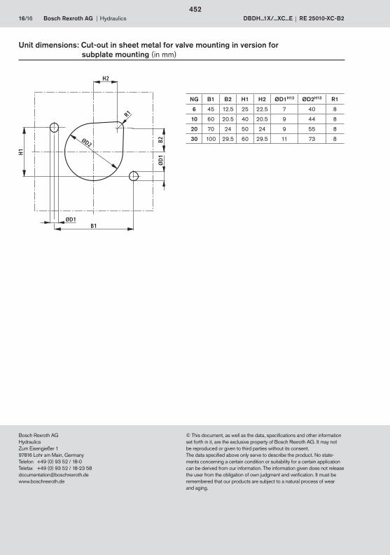
16/16 Bosch Rexroth AG Hydraulics DBDH...1X/...XC...E RE 25010-XC-B2
Bosch Rexroth AGHydraulicsZum Eisengießer 197816 Lohr am Main, GermanyTelefon +49 (0) 93 52 / 18-0Telefax +49 (0) 93 52 / 18-23 [email protected]
© This document, as well as the data, specifications and other information set forth in it, are the exclusive property of Bosch Rexroth AG. It may not be reproduced or given to third parties without its consent.The data specified above only serve to describe the product. No state-ments concerning a certain condition or suitability for a certain application can be derived from our information. The information given does not release the user from the obligation of own judgment and verification. It must be remembered that our products are subject to a natural process of wear and aging.
Unit dimensions: Cut-out in sheet metal for valve mounting in version for subplate mounting (in mm)
NG B1 B2 H1 H2 ØD1H13 ØD2H13 R1
6 45 12.5 25 22.5 7 40 8
10 60 20.5 40 20.5 9 44 8
20 70 24 50 24 9 55 8
30 100 29.5 60 29.5 11 73 8
452

1/8
Twin throttle-type check valve, directly operated
Type Z2FS 6...XC
Nominal size 6Unit series 4XMaximum operating pressure 315 barMaximum flow rate 80 l/min
RE 27506-XC-B2/06.09Replaces: 08.06
Information on explosion protection:
Range of application in accordance with the Explosion Protection Directive and type of protection
– Range of application as per Directive 94/9/EG IM2, II2G, II2D
– Type of protection of valve: c (EN 13463-5:2004-03)
ATEX units For potentially explosive atmospheres Part II Technical Data Sheet
What you need to know about these Operating Instructions
These Operating Instructions apply to the explosion-proof version of Rexroth valves, and consist of the following three parts:
Part I General Information RE 07010-X-B1 Part II Technical Data Sheet RE 27506-XC-B2 Part III Product-specific Instructions RE 27506-XC-B3
You can find further information on the correct handling of Rexroth hydraulic products in our publication “General Product Information on Hydraulic Products”, RE 07008.
RE 27506-XC-B0
TB0041
453

2/8 Bosch Rexroth AG Hydraulics Z2FS 6...XC RE 27506-XC-B2
Overview of Contents
Contents Page
Features 2
Ordering data and scope of delivery 3
Function, sectional diagram 4
Symbols 4
Technical data 5
Information on explosion protection 5
Characteristic curves 6
Unit dimensions 7
Features
– Modular valve • Position of ports to ISO 4401-03-02-0-05 with
tension pin and locating bore • Adjusting screw with lock nut and protective cap
• For limiting the main or pilot flow of two consumer ports
• For inlet or outlet throttling
454
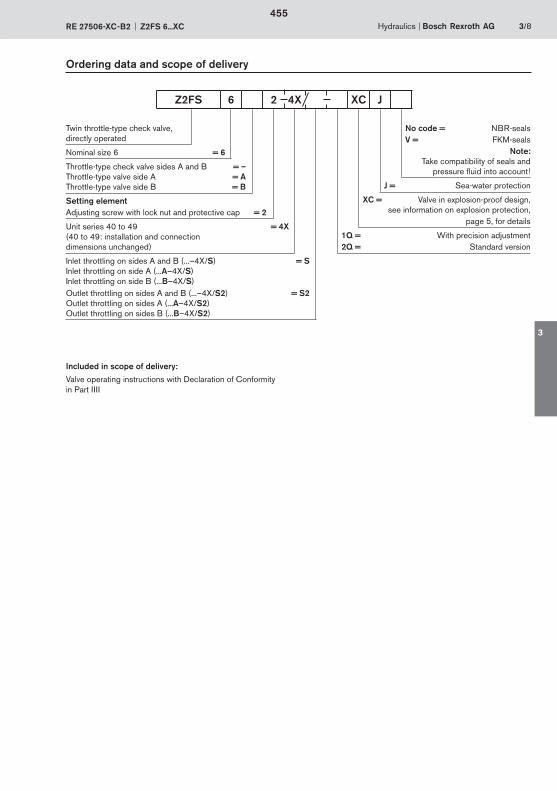
Hydraulics Bosch Rexroth AGRE 27506-XC-B2 Z2FS 6...XC 3/8
Ordering data and scope of delivery
Twin throttle-type check valve,directly operated
Nominal size 6 = 6
Throttle-type check valve sides A and B = –Throttle-type valve side A = AThrottle-type valve side B = B
Setting elementAdjusting screw with lock nut and protective cap = 2
Unit series 40 to 49 = 4X(40 to 49: installation and connection dimensions unchanged)
Inlet throttling on sides A and B (...–4X/S) = SInlet throttling on side A (...A–4X/S) Inlet throttling on side B (...B–4X/S) Outlet throttling on sides A and B (...–4X/S2) = S2Outlet throttling on sides A (...A–4X/S2) Outlet throttling on sides B (...B–4X/S2)
No code = NBR-seals V = FKM-seals
Note:Take compatibility of seals and
pressure fluid into account !
J = Sea-water protection
XC = Valve in explosion-proof design,see information on explosion protection,
page 5, for details
1Q = With precision adjustment2Q = Standard version
Included in scope of delivery:
Valve operating instructions with Declaration of Conformity in Part IIII
Z2FS 6 2 4X XC J
455
3
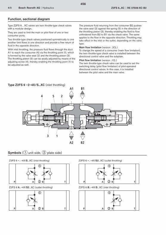
254
3 1
A1 B1
A2 B2
4/8 Bosch Rexroth AG Hydraulics Z2FS 6...XC RE 27506-XC-B2
Function, sectional diagram
Type Z2FS 6 –2–4X/S...XC (inlet throttling)
Type Z2FS 6…XC valves are twin throttle-type check valves with a modular design.
They are used to limit the main or pilot flow of one or two consumer ports.
Two throttle-type check valves positioned symmetrically to one another limit flows in one direction and provide a free return of fluid in the opposite direction.
With inlet throttling, the pressure fluid flows through the duct A1 to reach the consumer A2 via the throttling point (1), which is formed by the valve seat (2) and the throttling piston (3). The throttling piston (3) can be axially adjusted by means of the adjusting screw (4), thereby enabling the throttling point (1) to be adjusted as well.
The pressure fluid returning from the consumer B2 pushes the valve seat (2) against the spring (5) in the direction of the throttling piston (3), thereby enabling the fluid to flow unhindered from B2 to B1 via the check valve. The same applies to the flow in the opposite direction. Throttling may take effect in the inlet or the outlet, depending on the valve type.
Main flow limitation (version ..2Q..)To change the speed of a consumer (main flow limitation), the twin throttle-type check valve is installed between the directional control valve and the subplate.
Pilot flow limitation (version ..1Q..)The twin throttle-type check valve can be used to set the switching delay (pilot flow limitation) of pilot-operated directional control valves. In this case, it is installed between the pilot valve and the main valve.
Symbols ( 1 unit side, 2 plate side)
Z2FS 6 –..–4X/S...XC (inlet throttling) Z2FS 6 –..–4X/S2...XC (outlet throttling)
TP A B
1
2 TP A B
1
2
Z2FS 6 A..–4X/S2...XC (outlet throttling) Z2FS 6 B..–4X/S...XC (inlet throttling)
TP A B
1
2 TP A B
1
2
456
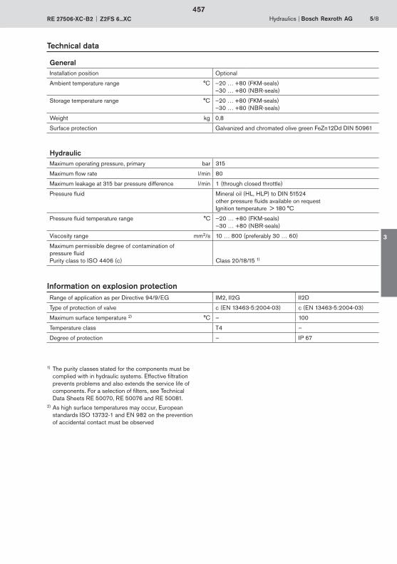
Hydraulics Bosch Rexroth AGRE 27506-XC-B2 Z2FS 6...XC 5/8
Technical data
GeneralInstallation position Optional
Ambient temperature range °C –20 … +80 (FKM-seals)–30 … +80 (NBR-seals)
Storage temperature range °C –20 … +80 (FKM-seals)–30 … +80 (NBR-seals)
Weight kg 0,8
Surface protection Galvanized and chromated olive green FeZn12Dd DIN 50961
HydraulicMaximum operating pressure, primary bar 315
Maximum flow rate l/min 80
Maximum leakage at 315 bar pressure difference l/min 1 (through closed throttle)
Pressure fluid Mineral oil (HL, HLP) to DIN 51524other pressure fluids available on requestIgnition temperature > 180 °C
Pressure fluid temperature range °C –20 … +80 (FKM-seals)–30 … +80 (NBR-seals)
Viscosity range mm2/s 10 … 800 (preferably 30 … 60)
Maximum permissible degree of contamination of pressure fluidPurity class to ISO 4406 (c) Class 20/18/15 1)
1) The purity classes stated for the components must be complied with in hydraulic systems. Effective filtration prevents problems and also extends the service life of components. For a selection of filters, see Technical
Data Sheets RE 50070, RE 50076 and RE 50081.2) As high surface temperatures may occur, European
standards ISO 13732-1 and EN 982 on the prevention of accidental contact must be observed
Range of application as per Directive 94/9/EG IM2, II2G II2D
Type of protection of valve c (EN 13463-5:2004-03) c (EN 13463-5:2004-03)
Maximum surface temperature 2) °C – 100
Temperature class T4 –
Degree of protection – IP 67
Information on explosion protection
457
3
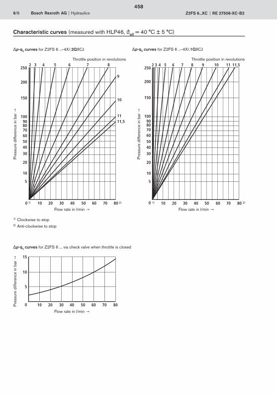
2 3 4 5 6 7 8
9
10
11
250
200
150
100908070605040
30
20
10
5
0 10 20 30 40 50 60 70 80
11,5
2 3 4 5 6 7 8250
200
150
100908070605040
30
20
10
5
0 10 20 30 40 50 60 70 80
9 10 11 11,5
15
10
5
0 10 20 30 40 50 60 70 80
6/8 Bosch Rexroth AG Hydraulics Z2FS 6...XC RE 27506-XC-B2
Characteristic curves (measured with HLP46, oil = 40 °C ± 5 °C)
p-qV curves for Z2FS 6 ..–4X/.2QXCJ p-qV curves for Z2FS 6 ..–4X/.1QXCJ
p-qV curves for Z2FS 6 ... via check valve when throttle is closed
Throttle position in revolutions Throttle position in revolutions
Pre
ssur
e di
ffere
nce
in b
ar
Pre
ssur
e di
ffere
nce
in b
ar
Flow rate in l/min Flow rate in l/min
Flow rate in l/min
Pre
ssur
e di
ffere
nce
in b
ar
1) 2) 1) 2)
1) Clockwise to stop 2) Anti-clockwise to stop
458
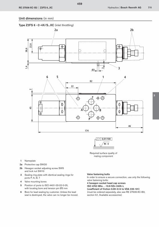
T
A B
P
6
38,6
1,4
1
2b
3
452
5 482
174
22
46
2a22
,6
Ø3
3
Hydraulics Bosch Rexroth AGRE 27506-XC-B2 Z2FS 6...XC 7/8
Unit dimensions (in mm)
1 Nameplate
2a Protective cap SW20
2b Hexagon socket adjusting screw SW5 and lock nut SW10
3 Sealing ring plate with identical sealing rings for ports P, A, B, T
4 Valve mounting bores
5 Position of ports to ISO 4401-03-02-0-05, with locating bore and tension pin Ø3 mm
6 Bore for lead sealing by customer. Unless the lead seal is destroyed, the valve can no longer be moved.
Required surface quality of mating component
Rt 4
0,01/100
Valve fastening boltsIn order to ensure a secure connection, use only the following valve fastening bolts:4 hexagon socket head cap screws ISO 4762-M5x…-10.9-flZn-240h-L (coefficient of friction 0.09–0.14 to VDA 235-101) (must be ordered separately, also see RE 27506-XC-B3, section 9.1, Available accessories)
Type Z2FS 6 –2–4X/S...XC (inlet throttling)
459
3

Bosch Rexroth AGHydraulicsZum Eisengießer 197816 Lohr am Main, GermanyTelefon +49 (0) 93 52 / 18-0Telefax +49 (0) 93 52 / 18-23 [email protected]
8/8 Bosch Rexroth AG Hydraulics Z2FS 6...XC RE 27506-XC-B2
© This document, as well as the data, specifications and other information set forth in it, are the exclusive property of Bosch Rexroth AG. It may not be reproduced or given to third parties without its consent.The data specified above only serve to describe the product. No state-ments concerning a certain condition or suitability for a certain application can be derived from our information. The information given does not release the user from the obligation of own judgment and verification. It must be remembered that our products are subject to a natural process of wear and aging.
Notes
460
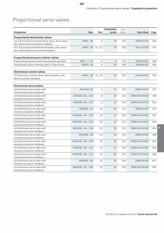
RE 00112-10, Edition: 2013-12, Bosch Rexroth AG
Designation Type SizeComponent
seriespmax
in bar Data sheet Page
Proportional servo valves
Contents | Proportional servo valves | Explosion protection
Proportional directional valves4/2 and 4/3 proportional directional valves, direct opera-ted, without electrical position feedback
4WRA...XE 6 2X 315 29055-XE-B2 463
4/2, 4/3 proportional directional valves, pilot opera-ted, without electrical position feedback
4WRZ...XE 10...32 7X 350 29115-XE-B2 475
Proportional pressure control valvesProportional pressure relief valve directly operated DBET.../...XE 6 6 420 29162-XE-B2 493Proportional pressure reducing valve in 3-way version 3DREP...XE 6 2X 100 29184-XE-B2 505
Directional control valves4/3 directional control valves, pilot operated, with electric position feedback
4WRD...XN 10...35 5X 350 29094-XN-B2 515
Directional servo-valves4/3 directional servo-valve with mechanical position feedback
4WS2EM..XN 6 2X 315 29564-XN-B2 537
4/3 directional servo-valve with mechanical position feedback
4WS2EM..XN...-100 6 2X 315 29564-XN-100-B2 549
4/3 directional servo-valve with mechanical position feedback
4WS2EM..XN...-102 6 2X 315 29564-XN-102-B2 561
4/3 directional servo-valve with mechanical position feedback
4WS2EM...XH 10 5X 315 29583-XH-B2 573
4/3 directional servo-valve with mechanical position feedback
4WS2EM...XH...-100 10 2X 315 29583-XH-100-B2 587
4/3 directional servo-valve with mechanical position feedback
4WS2EM...XH...-102 10 2X 315 29583-XH-102-B2 601
4/3 directional servo-valve with mechanical position feedback
4WS2EM...XH...-104 10 5X 315 29583-XH-104-B2 615
4/3 directional servo-valve with mechanical position feedback
4WS2EM...XN 10 5X 315 29583-XN-B2 629
4/3 directional servo-valve with mechanical position feedback
4WS2EM...XN...-100 10 5X 315 29583-XN-100-B2 641
4/3 directional servo-valve with mechanical position feedback
4WS2EM...XN...-102 10 5X 315 29583-XN-102-B2 653
4/3 directional servo-valve with mechanical position feedback
4WS2EM...XN...-114 10 5X 315 29583-XN-114-B2 665
4/3 directional servo-valve with mechanical position feedback
4WS2EM...XD 10 5X 315 29583-XD-B2 677
4/3 directional servo-valve with mechanical position feedback
4WS2EM...XD…-100 10 5X 315 29583-XD-100-B2 691
1
2
3
4
5
6
461
4

Bosch Rexroth AG, RE 00112-10, Edition: 2013-12
462

463

464
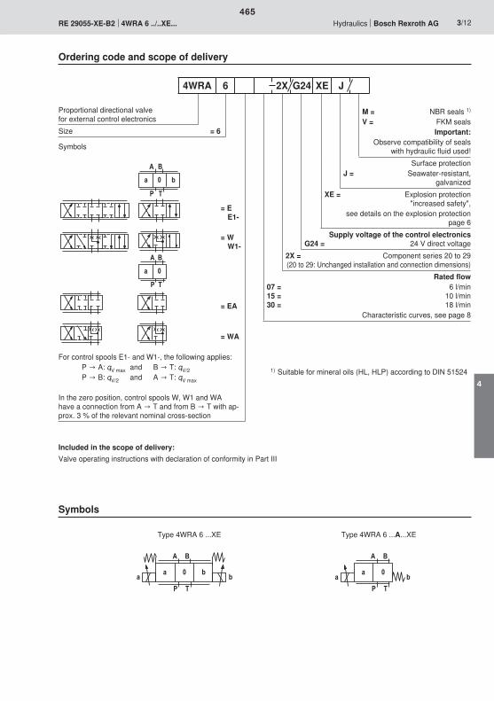
P T
a 0 b
A B
a 0
A B
P T
A B
P T
a 0a bP T
A B
a 0 ba b
465
4
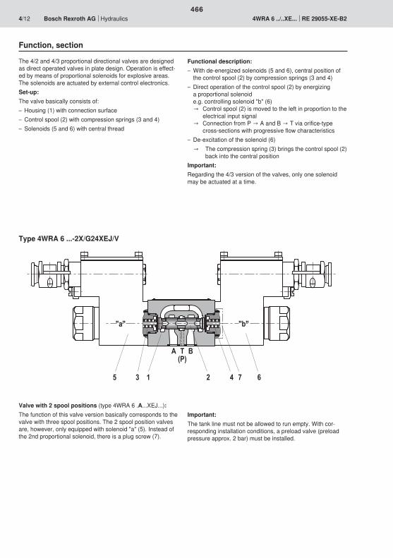
"a" "b"
A T(P)
B
5 3 1 2 4 7 6
466
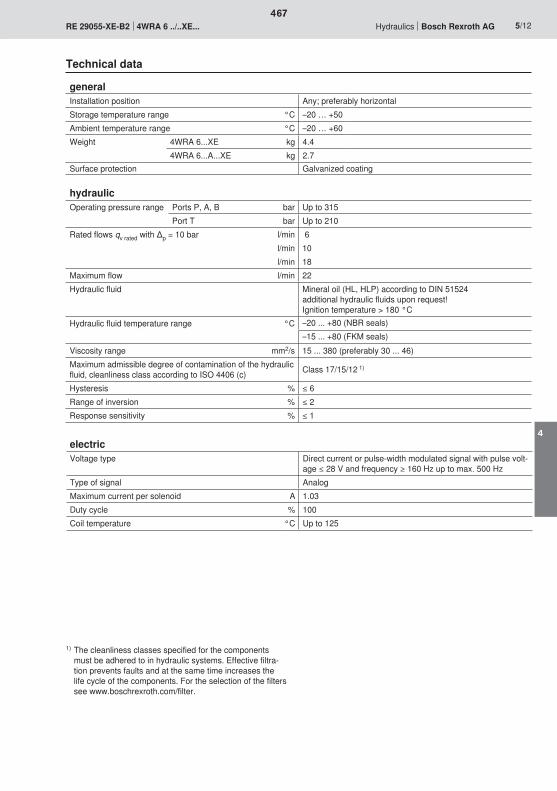
467
4
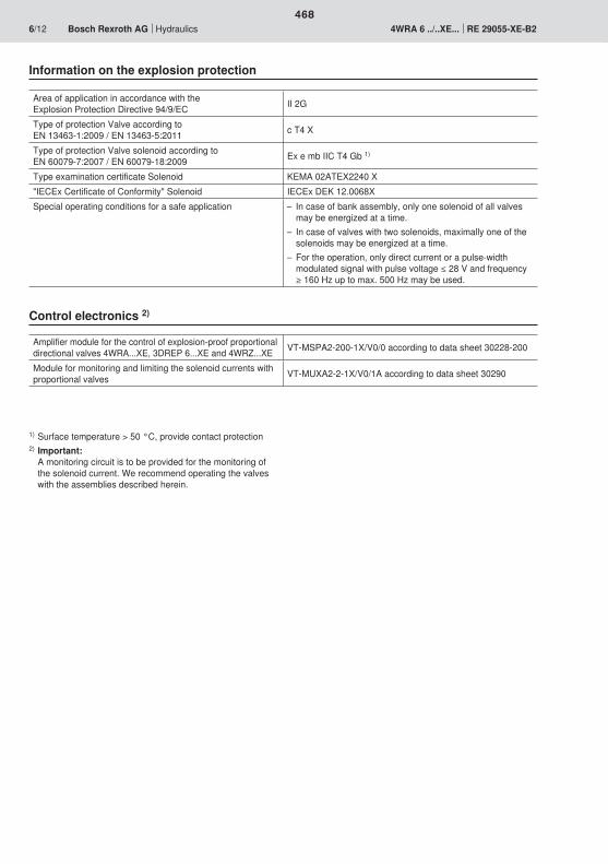
468

2
3
1
�;<�
�<;��
��
��
������
469
4
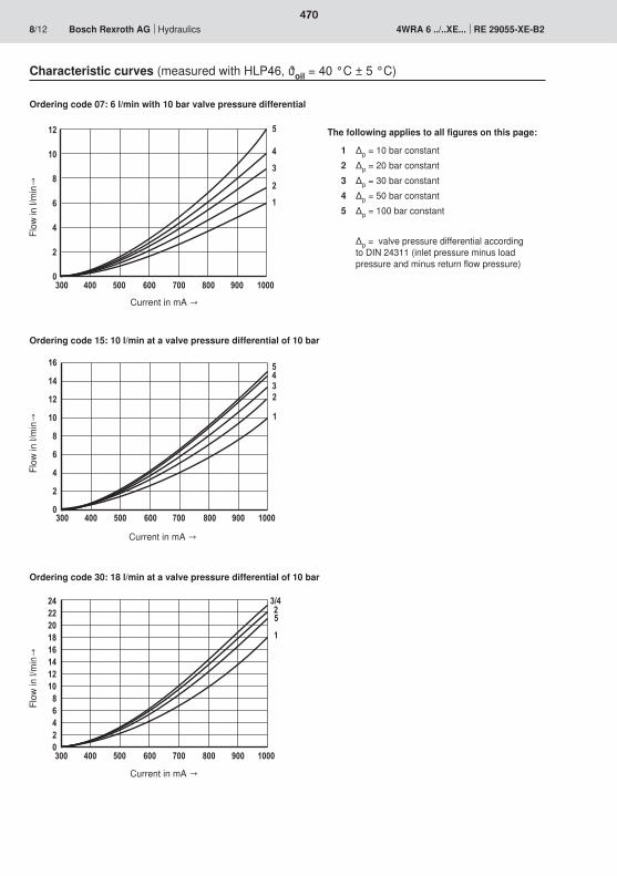
300 900800700600500400 1000
8
6
4
0
2
12
10
5
1
2
3
4
300 900800700600500400 1000
8
6
4
0
2
12
10
5
1
23414
16
300 900800700600500400 1000
864
02
1210
1416
24222018 1
5
3/42
470
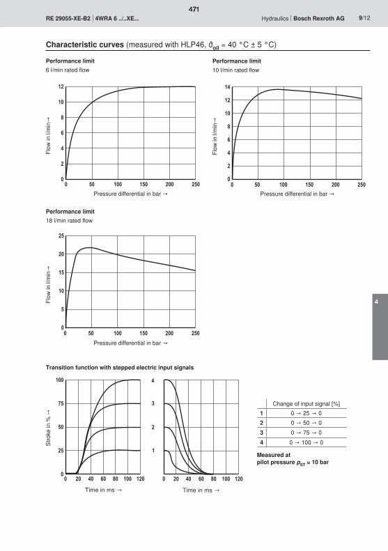
0 25020015010050
8
6
4
0
2
12
10
0 25020015010050
8
6
4
0
2
12
10
14
0 25020015010050
15
10
0
5
20
25
0
50
25
75
100
604020 80 1000 120 604020 80 100 120
4
3
2
1
0
471
4
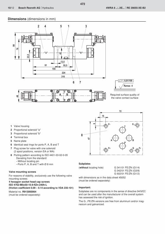
13,542
91 55,5155
224310
"a" "b"
A B
P
2 4 5 1 3
6 7
9976
T
23,5
48
Rzmax 4
0,01/100
F1
F3F4
F2
G
T
PBA
72
15
47
8
8
472
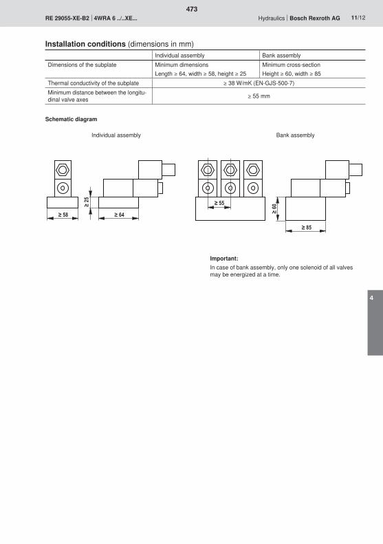
473
4

474

475
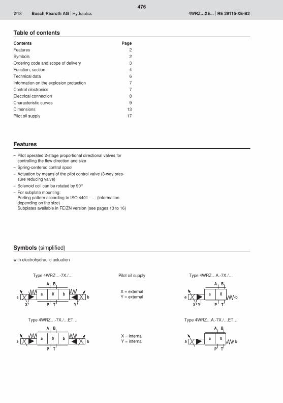
� '
� $
5 � 8
� �
5 8
� '
� $
5 �8
� �
�
� '
� $
5 � 85 8
� '
� $
5 �8�
476
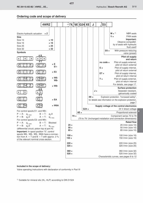
$�5 � 8 5 � 8
� '
5 � 5 �$�
� '
477
4
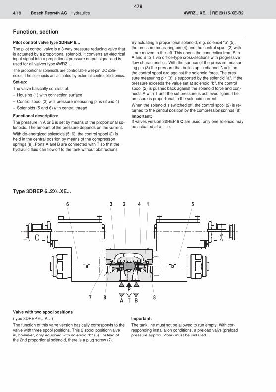
6 2 4 51
7
3
P
BTA
"a" "b"
8 8
478
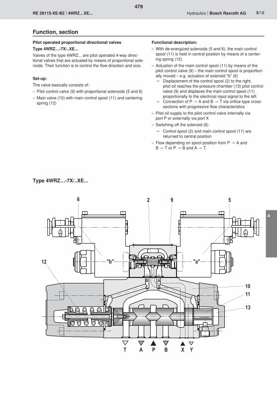
T A P YX
AB10
13
B
12
11
6 2 59
"b" "a"
479
4
480
481
4
2
3
1
�;<�
�<;��
��
��
������
482
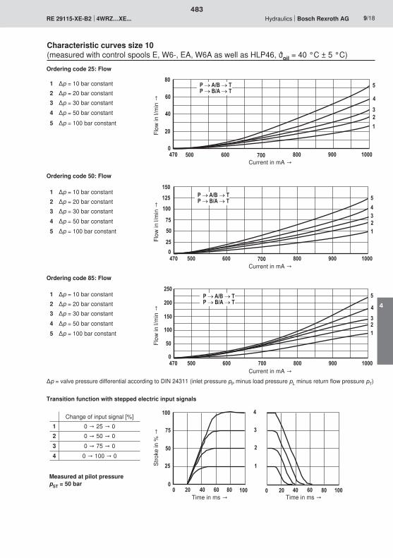
���
�
���
�
����1��3��2��0����2�
��
��������'���$����'�����$
�
��
���
�
�
�
2
����1��3��2��0����2�
��
�� ������'���$����'�����$
���
�
��
�
����1��3��2��0����2�
3�
0�
������'���$����'�����$
��
�
�
�
�
���
2
�
�
�
� �� � 0� 3� ��� � �� � 0� 3� ���
483
4
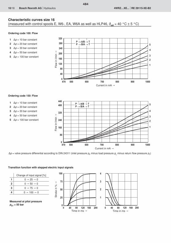
�
�
�
2
���
���3�� �0� ���� ���3�� �0� ����
�
�
�
�0�
�
�
3�
���
����1��3��2��0����2�
��
���
���
�3�������'���$����'�����$
�
�
�
��
�
3�
�0�
�
����1��3��2��0����2�
��
���
������'���$����'�����$
�
�
�
484
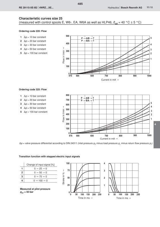
��
�
���
���
���
��
����1��3��2��0����2�
������'���$����'�����$
�
�
�
3��
�
���
���
���
��
��
0��
2��
����1��3��2��0����2�
������'���$����'�����$
��
�
�
�
�
2
���
������ ��� ���
�
�
�
������ ��� ���
485
4
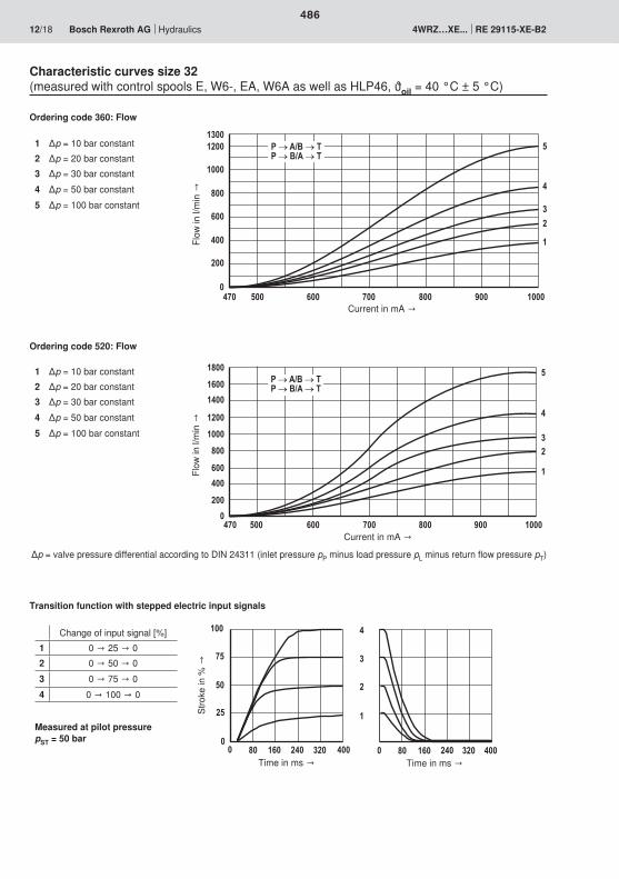
3��
�
���
��
0��
����1��3��2��0����2�
�
�
�
��������
����
������'���$����'�����$
�0��
�
���
��
0��
3��
����
����
���
����1��3��2��0����2�
������'���$����'�����$
��
�
�3��
�
�
�
���
2
�
�
�
� 3� �0� �� ��� �� � 3� �0� �� ��� ��
486
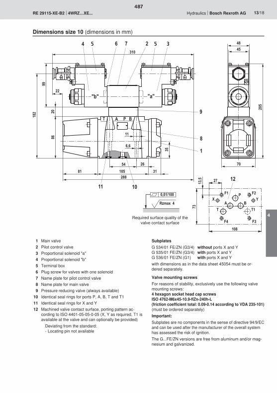
7
1011
BPAT
86
182
353110581
9
8
1
326499
310
288
4548
20
70
205
54 26
6,6
11
5
"a""b"
5
22
��3
�2
2���
)
�� ���
'�
$�$
���
��
� �Rzmax 4
0,01/100
487
4
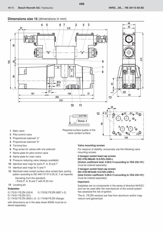
7
9
3264
99
5310
20192
A B Y
27101 154 37
96
18
1110
292333
Ø33
13
4548
215
92
43Ø11Ø18
"b" "a"
523
�3
�1
1
��
��
��
�
'�
�$
���
�
�
�0��
����
Rzmax 4
0,01/100
488
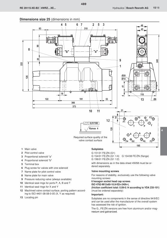
1110
19
122366373
191 53
1
126
222
7
9
3264
99
531063
20
414
"b" "a"8
Ø20Ø14
45
118
48
Ø613
245
5
�1
����
�
�
��
��
�
'��
$
���
�
�
�0��
����
Rzmax 4
0,01/100
489
4
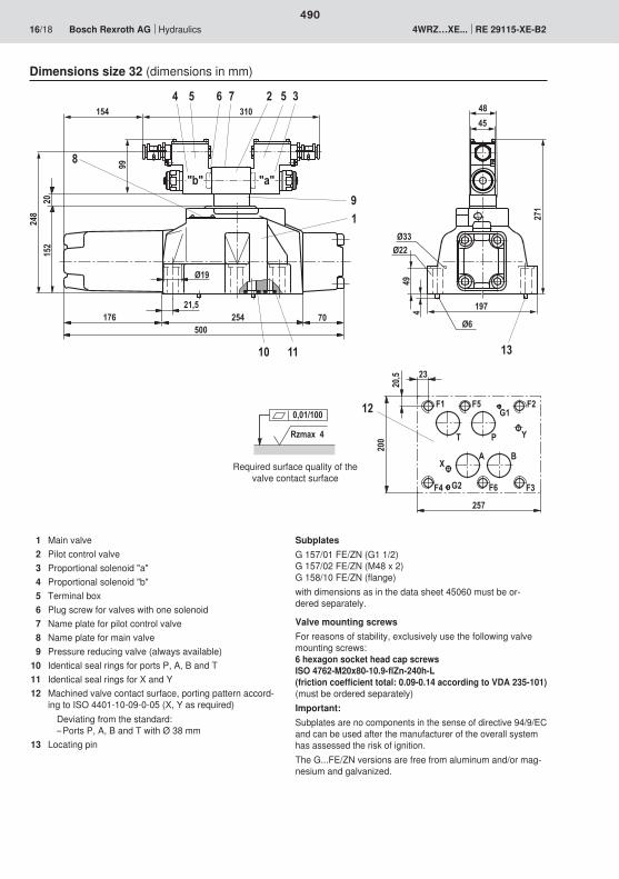
25421,5
70176500
152
248
1110
1
7
9
3264
99
5310
20
Ø19
8
197
494
Ø33Ø22
Ø6
13
4548
271
5
"a""b"
154
�2
����
�
��)
�� ��
�
'��
$
���
�
�
�0��
����
Rzmax 4
0,01/100
490
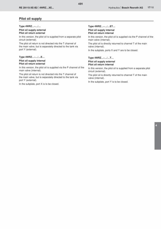
491
4

492
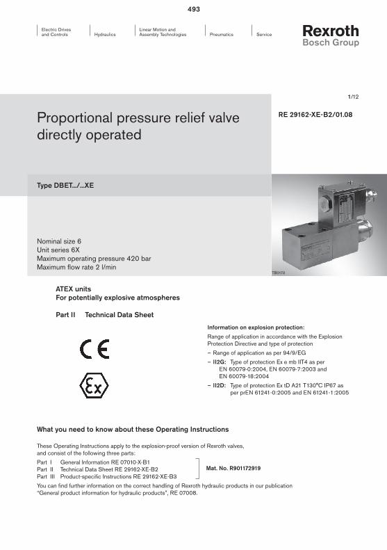
1/12
Proportional pressure relief valve directly operated
Type DBET.../...XE
Nominal size 6Unit series 6XMaximum operating pressure 420 barMaximum flow rate 2 l/min
RE 29162-XE-B2/01.08
TB0173
Information on explosion protection:
Range of application in accordance with the Explosion Protection Directive and type of protection
– Range of application as per 94/9/EG
– II2G: Type of protection Ex e mb IIT4 as per EN 60079-0:2004, EN 60079-7:2003 and EN 60079-18:2004
– II2D: Type of protection Ex tD A21 T130°C IP67 as per prEN 61241-0:2005 and EN 61241-1:2005
ATEX units For potentially explosive atmospheres Part II Technical Data Sheet
What you need to know about these Operating Instructions
These Operating Instructions apply to the explosion-proof version of Rexroth valves, and consist of the following three parts:
Part I General Information RE 07010-X-B1 Part II Technical Data Sheet RE 29162-XE-B2 Part III Product-specific Instructions RE 29162-XE-B3
You can find further information on the correct handling of Rexroth hydraulic products in our publication “General product information for hydraulic products”, RE 07008.
Mat. No. R901172919
493
2/12 Bosch Rexroth AG Hydraulics DBET.../...XE RE 29162-XE-B2
Overview of Contents
Contents Page
Features 2
Ordering data and scope of delivery 3
Symbols 3
Function, sectional diagram 4
Technical data 5 … 6
Information on explosion protection 6
Electrical connection 7
Characteristic curves 8 … 9
Unit dimensions 10
Installation conditions 11
Features
– Directly operated proportional pressure relief valve with solenoid actuation for proper use in potentially explosive atmospheres
– For subplate mounting:Mounting hole configuration as per ISO 4401-03-02-0-05
– Wet-pin DC solenoid
– Electrical connection is a single terminal with cable gland
– The metal outer parts are galvanized for protection against corrosion (resistance to seawater)
494
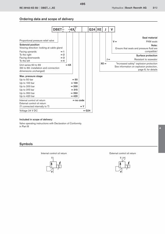
Hydraulics Bosch Rexroth AGRE 29162-XE-B2 DBET.../...XE 3/12
Ordering data and scope of delivery
Symbols
Internal control oil return External control oil return
P
T
P
T Y
Included in scope of delivery:
Valve operating instructions with Declaration of Conformity in Part III
DBET 6X G24 XE J V
Proportional pressure relief valve
Solenoid positionViewing direction: looking at cable gland
Facing upwards = 1To the right = 2Facing downwards = 3To the left = 4
Unit series 60 to 69 = 6X (60 to 69: installation and connection dimensions unchanged)
Max. pressure stageUp to 50 bar = 50Up to 100 bar = 100Up to 200 bar = 200Up to 315 bar = 315Up to 350 bar = 350Up to 420 bar = 420
Internal control oil return = no code External control oil return (Y connected internally to T) = Y
Voltage 24 V DC = G24
Seal material
V = FKM seals
Note:Ensure that seals and pressure fluid are
compatible!
Surface protection
J = Resistant to seawater
XE = ”Increased safety” explosion protectionSee information on explosion protection,
page 6, for details
495
4
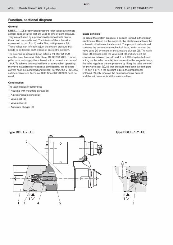
PT
Y
2
1 4 53 3
PT
4/12 Bosch Rexroth AG Hydraulics DBET.../...XE RE 29162-XE-B2
Function, sectional diagram
General
DBET…/…XE proportional pressure relief valves are remote control poppet valves that are used to limit system pressure. They are actuated by a proportional solenoid with central thread and removable coil. The interior of the solenoid is connected to port T or Y, and is filled with pressure fluid. These valves can infinitely adjust the system pressure that needs to be limited, on the basis of an electric setpoint.
The solenoid is actuated by an external VT-MSPA1-200 amplifier (see Technical Data Sheet RE 30233-200). This am-plifier must not supply the solenoid with a current in excess of 1.0 A. To achieve this required level of safety when operating the valve in a potentially explosive atmosphere, the solenoid current must be monitored and limited. For this, the VT-MUXA2 safety module (see Technical Data Sheet RE 30290) must be used.
Construction
The valve basically comprises:
– Housing with mounting surface (1)
– A proportional solenoid (2)
– Valve seat (3)
– Valve cone (4)
– Armature plunger (5)
Basic principle
To adjust the system pressure, a sepoint is input in the trigger electronics. Based on this setpoint, the electronics actuate the solenoid coil with electrical current. The proportional solenoid converts the current to a mechanical force, which acts on the valve cone (4) by means of the armature plunger (5). The valve cone (4) presses onto the valve seat (3) and shuts off the connection between ports P and T or Y. If the hydraulic force acting on the valve cone (4) is equivalent to the magnetic force, the valve regulates the set pressure by lifting the valve cone (4) off the valve seat (3), so that pressure fluid can flow from port P to port T or Y. If the setpoint is zero, the proportional solenoid (2) only receives the minimum control current, and the set pressure is at the minimum level.
Type DBET.../...XE Type DBET.../...Y...XE
496
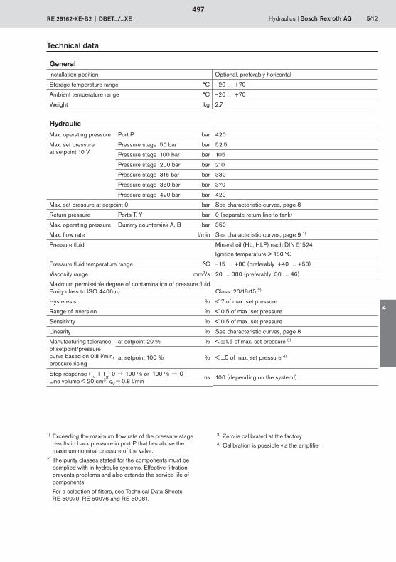
Hydraulics Bosch Rexroth AGRE 29162-XE-B2 DBET.../...XE 5/12
Technical data
GeneralInstallation position Optional, preferably horizontal
Storage temperature range °C –20 … +70
Ambient temperature range °C –20 … +70
Weight kg 2.7
HydraulicMax. operating pressure Port P bar 420
Max. set pressureat setpoint 10 V
Pressure stage 50 bar bar 52.5
Pressure stage 100 bar bar 105
Pressure stage 200 bar bar 210
Pressure stage 315 bar bar 330
Pressure stage 350 bar bar 370
Pressure stage 420 bar bar 420
Max. set pressure at setpoint 0 bar See characteristic curves, page 8
Return pressure Ports T, Y bar 0 (separate return line to tank)
Max. operating pressure Dummy countersink A, B bar 350
Max. flow rate l/min See characteristic curves, page 9 1)
Pressure fluid Mineral oil (HL, HLP) nach DIN 51524
Ignition temperature > 180 °C
Pressure fluid temperature range °C –15 … +80 (preferably +40 … +50)
Viscosity range mm2/s 20 … 380 (preferably 30 … 46)
Maximum permissible degree of contamination of pressure fluidPurity class to ISO 4406(c) Class 20/18/15 2)
Hysteresis % < 7 of max. set pressure
Range of inversion % < 0.5 of max. set pressure
Sensitivity % < 0.5 of max. set pressure
Linearity % See characteristic curves, page 8
Manufacturing tolerance of setpoint/pressure curve based on 0.8 l/min, pressure rising
at setpoint 20 % % < ±1.5 of max. set pressure 3)
at setpoint 100 % % < ±5 of max. set pressure 4)
Step response (Tu + Tg) 0 100 % or 100 % 0Line volume < 20 cm3; qV = 0.8 l/min
ms 100 (depending on the system!)
1) Exceeding the maximum flow rate of the pressure stage results in back pressure in port P that lies above the maximum nominal pressure of the valve.2) The purity classes stated for the components must be complied with in hydraulic systems. Effective filtration prevents problems and also extends the service life of components. For a selection of filters, see Technical Data Sheets RE 50070, RE 50076 and RE 50081.
3) Zero is calibrated at the factory4) Calibration is possible via the amplifier
497
4
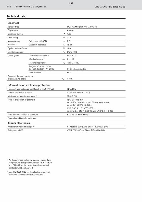
6/12 Bosch Rexroth AG Hydraulics DBET.../...XE RE 29162-XE-B2
1) As the solenoid coils may reach a high surface temperature, European standards ISO 13732-1 and EN 982 on the prevention of accidental contact must be observed
2) See RE 30290-B2 for the electric circuitry of the valve, amplifier and safety module.
Information on explosion protectionRange of application as per Directive RL 94/9/EG II2G, II2D
Type of protection of valve c (EN 13463-5:2001-01)
Maximum surface temperature 1) 130°C (T4)
Type of protection of solenoid II2G Ex e mb IIT4 as per EN 60079-0:2004, EN 60079-7:2003 as per EN 60079-18:2004
II2D Ex tD A21 T130°C IP67as per prEN 61241-0:2005 and EN 61241-1:2005
Type test certification of solenoid EX5 06 04 39919 009
Special conditions for safe use
Trigger electronicsAmplifier in modular design 2) VT-MSPA1-200 (Data Sheet RE 30223-200)
Safety module 2) VT-MUXA2-1(Data Sheet RE 30290-B2)
ElectricalVoltage type DC; PWM signal 100 … 500 Hz
Signal type Analog
Maximum current A 1.03
Limit rating W 13.3
Solenoid coil resistance
Cold value at 20 °C 8.3
Maximum hot value 12.56
Cyclic duration factor % 100
Coil temperature °C Up to 130
Cable gland Threaded connection M20 x 1.5
Cable diameter mm 6 … 12
Thermal resistance °C –20 … +130
Degree of protection to EN 60529:1991+A1:2000 IP 67 when mounted
Seal material FKM
Required thermal resistanceof connecting cable °C 115
Technical data
498
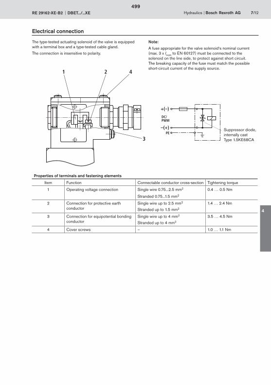
+(–)
–(+)PE
DC/PWM
1 2 4
3
Hydraulics Bosch Rexroth AGRE 29162-XE-B2 DBET.../...XE 7/12
Electrical connection
The type-tested actuating solenoid of the valve is equipped with a terminal box and a type-tested cable gland.
The connection is insensitive to polarity.
Note:
A fuse appropriate for the valve solenoid‘s nominal current (max. 3 x Inom to EN 60127) must be connected to the solenoid on the line side, to protect against short circuit. The breaking capacity of the fuse must match the possible short-circuit current of the supply source.
Properties of terminals and fastening elements
Item Function Connectable conductor cross-section Tightening torque
1 Operating voltage connection Single wire 0.75...2.5 mm2 0.4 … 0.5 Nm
Stranded 0.75...1.5 mm2
2 Connection for protective earth conductor
Single wire up to 2.5 mm2
Stranded up to 1.5 mm2
1.4 … 2.4 Nm
3 Connection for equipotential bonding conductor
Single wire up to 4 mm2
Stranded up to 4 mm2
3.5 … 4.5 Nm
4 Cover screws – 1.0 … 1.1 Nm
Suppressor diode, internally castType 1.5KE68CA
499
4
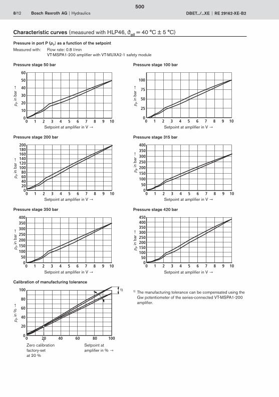
040 60 80 100
20
40
60
80
100
200
1)
8/12 Bosch Rexroth AG Hydraulics DBET.../...XE RE 29162-XE-B2
Characteristic curves (measured with HLP46, oil = 40 °C ± 5 °C)
Pressure in port P (pP) as a function of the setpoint
Measured with: Flow rate: 0.8 l/min VT-MSPA1-200 amplifier with VT-MUXA2-1 safety module
04 6 8 10
10
20
30
40
2
50
60
0 1 3 5 7 9
p P in
bar
Setpoint at amplifier in V
04 6 8 10
25
50
75
2
100
0 1 3 5 7 9
p P in
bar
Setpoint at amplifier in V
Pressure stage 50 bar Pressure stage 100 bar
p P in
%
Setpoint at amplifier in %
p P in
bar
04 6 8 10
80100
140
180
2
200
0 1 3 5 7 9
160
120
4060
200
4 6 8 10
100150
250
350
2
400
0 1 3 5 7 9
300
200
50
Pressure stage 200 bar
p P in
bar
Setpoint at amplifier in V Setpoint at amplifier in V
Pressure stage 315 bar
Calibration of manufacturing tolerance
04 6 8 10
100150
250
350
2
400
0 1 3 5 7 9
300
200
500
4 6 8 10
100150
250
350
2
450
0 1 3 5 7 9
300
200
50
400
p P in
bar
Setpoint at amplifier in V
Pressure stage 350 bar
p P in
bar
Setpoint at amplifier in V
Pressure stage 420 bar
Zero calibration factory-set at 20 %
1) The manufacturing tolerance can be compensated using the Gw potentiometer of the series-connected VT-MSPA1-200 amplifier.
500

Hydraulics Bosch Rexroth AGRE 29162-XE-B2 DBET.../...XE 9/12
Characteristic curves (measured with HLP46, oil = 40 °C ± 5 °C)
Pressure in port P (pP) as a function of the flow rate
VT-MSPA1-200 amplifier with VT-MUXA2-1 safety module.
00,4 0,8 1,2 1,6 2,0
10
20
30
40
50
60 5
4
3
2
10
1)
00,4 0,8 1,2 1,6 2,0
25
50
75
100
5
4
3
2
10
1)
1)
00,4 0,8 1,2 1,6 2,0
50
100
150
200
250 5
4
3
2
10
00,4 0,8 1,2 1,6 2,0
50100150200250300
350
5
4
3
2
10
400
1)315
00,4 0,8 1,2 1,6 2,0
50100150200250300
4204
3
2
10
350400
5
1)
3)
2)
00,4 0,8 1,2 1,6 2,0
50100150200250300
420 4
3
2
10
350400
5 2)
3)
p P in
bar
Flow rate in l/min
p P in
bar
Flow rate in l/min
p P in
bar
Flow rate in l/min
p P in
bar
Flow rate in l/min
p P in
bar
Flow rate in l/min
p P in
bar
Flow rate in l/min
Pressure stage 50 bar Pressure stage 100 bar
Pressure stage 200 bar Pressure stage 315 bar
Pressure stage 350 bar Pressure stage 420 bar
Applicable for all pressure stages:
Curve 1 = 0 % setpoint
Curve 2 = 25 % setpoint
Curve 3 = 50 % setpoint
Curve 4 = 75 % setpoint
Curve 5 = 100 % setpoint
The curves were measured without back pressure in port T (pT = 0 bar).
1) Flow rate limit of pressure stage2) Flow rate limit and maximum pressure3) Theoretical curve profile at a flow rate less than 0.2 l/min
501
4
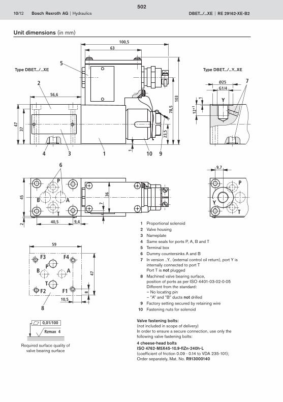
P
T
Y
9,7
Ø25G1/4
Y112
+1
7
P
T
B
F4F3
A
F1F2
59
10,5
847
8
P
T
36
45 B A
6
40,5
1
23,5
78,5
103
47
100,5
56,6
63
5
2
34 1 10 9
372 9,4
7
10/12 Bosch Rexroth AG Hydraulics DBET.../...XE RE 29162-XE-B2
Unit dimensions (in mm)
1 Proportional solenoid 2 Valve housing3 Nameplate 4 Same seals for ports P, A, B and T5 Terminal box6 Dummy countersinks A and B7 In version ..Y.. (external control oil return), port Y is
internally connected to port T Port T is not plugged
8 Machined valve bearing surface,position of ports as per ISO 4401-03-02-0-05Different from the standard:– No locating pin– ”A” and ”B” ducts not drilled
9 Factory setting secured by retaining wire10 Fastening nuts for solenoid
Valve fastening bolts: (not included in scope of delivery)In order to ensure a secure connection, use only the following valve fastening bolts:
4 cheese-head bolts ISO 4762-M5X45-10.9-flZn-240h-L(coefficient of friction 0.09 - 0.14 to VDA 235-101); Order separately, Mat. No. R913000140
0,01/100
Rzmax 4
Required surface quality of valve bearing surface
Type DBET.../...XE Type DBET.../...Y...XE
502
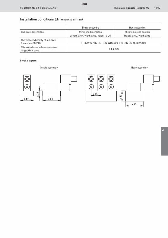
58 64
25 55
85
60
Hydraulics Bosch Rexroth AGRE 29162-XE-B2 DBET.../...XE 11/12
Installation conditions (dimensions in mm)
Single assembly Bank assembly
Subplate dimensions Minimum dimensions
Length 64, width 58, height 25
Minimum cross-section
Height 60, width 85
Thermal conductivity of subplate (based on 300°C) 35,2 W / (K · m), (EN-GJS-500-7 to DIN EN 1563:2005)
Minimum distance between valve longitudinal axes
55 mm
Block diagram
Single assembly Bank assembly
503
4

Bosch Rexroth AGHydraulicsZum Eisengießer 197816 Lohr am Main, GermanyTelefon +49 (0) 93 52 / 18-0Telefax +49 (0) 93 52 / 18-23 [email protected]
© This document, as well as the data, specifications and other information set forth in it, are the exclusive property of Bosch Rexroth AG. It may not be reproduced or given to third parties without its consent.The data specified above only serve to describe the product. No state-ments concerning a certain condition or suitability for a certain application can be derived from our information. The information given does not release the user from the obligation of own judgment and verification. It must be remembered that our products are subject to a natural process of wear and aging.
12/12 Bosch Rexroth AG Hydraulics DBET.../...XE RE 29162-XE-B2
Notes
504
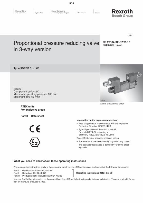
505

506
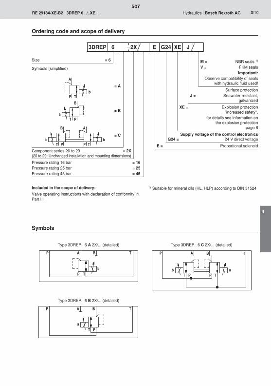
� $
�
8
�$
'
5� $
�
8
�$
'
5
� � ' $
� $8
�$
'
5� $
� $�
8
$�� '
5$ �
507
4
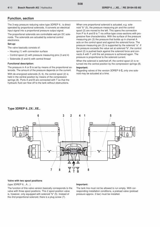
6 2 4 51
7
3
P
BTA
"a" "b"
8 8
508
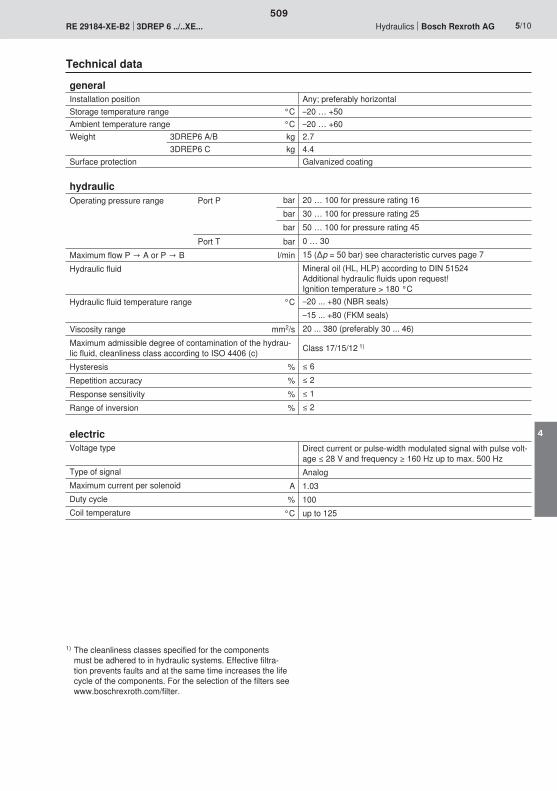
509
4
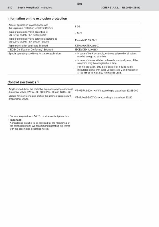
510
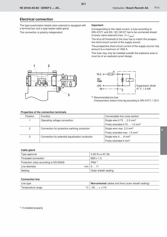
2
3
1
�;<�
�<;��
��
��
������
511
4

��
���
3�
0�
�
���
������ �� ��
��
��=��)��� ��=��)3��
��=��)0�� ��=��)��
�
���
�
�� � ���
���
�
��������
512
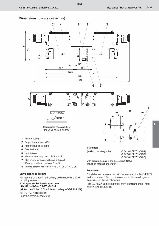
13,5
42
96,5 55,5160,5
235310
A B
P
2 4 5 1 3
6 7
9976
T
48
23,5
„a“ „b“
'
3
2
2�
�$
�
3
�
�� ��
� ��
Rzmax 4
0,01/100
513
4
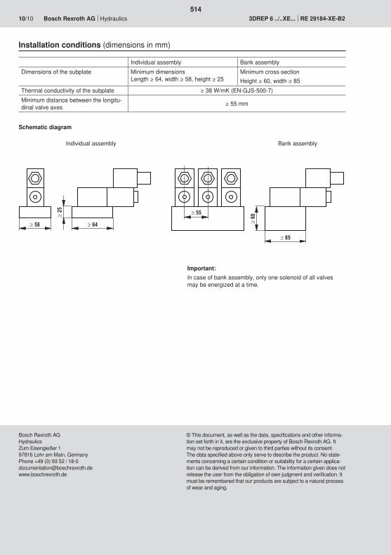
514

515
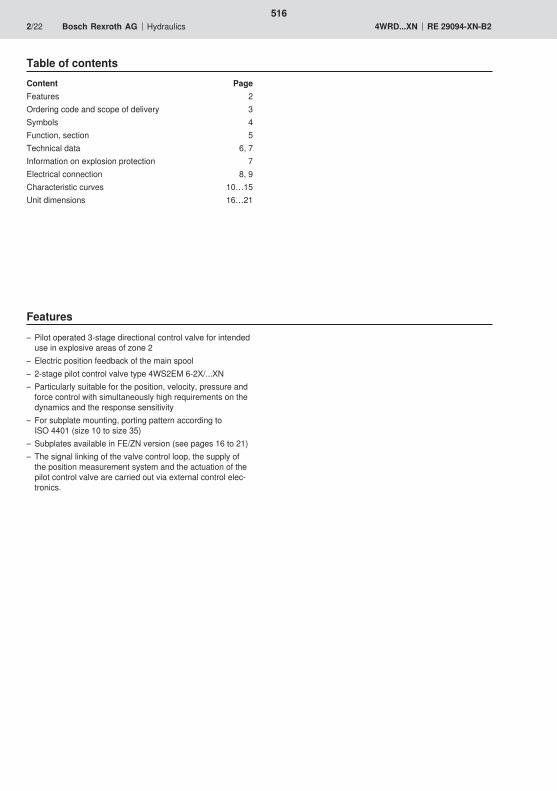
516
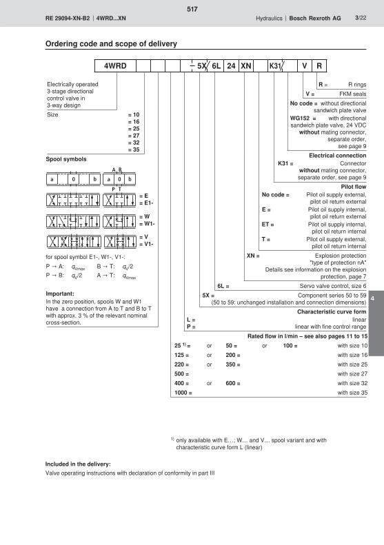
a 0 b a 0 b
A B
P T
517
4
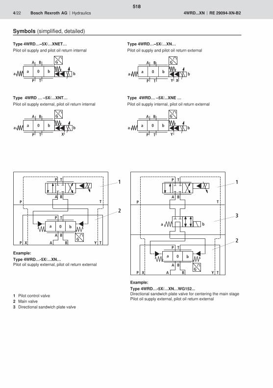
2
1
GX Y
a 0 b
A B
A B
P T
P T
A B
P T
P T
2
1
3
GX Y
a 0 b
A B
A B
P T
P T
A B
P T
P T
a b
G
a 0 b
A B
P T
a b
G
XY
a 0 b
A B
P T
a b
G
X
a 0 b
A B
P T
a b
G
Y
a 0 b
A B
P T
a b
518
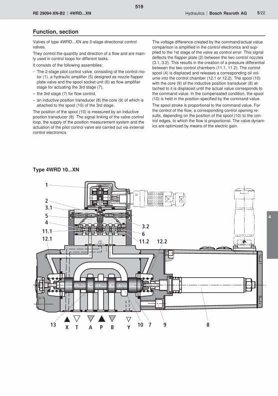
YBPATX 10 7 913
12.2
8
1
4
3.1
11.112.1
2
5
3.26
11.2
519
4
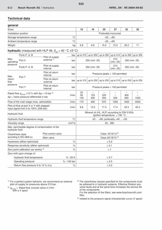
520
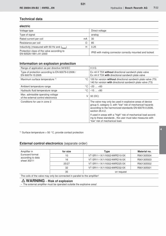
521
4
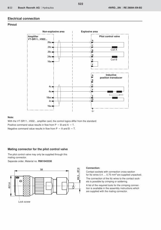
26a
24c
26c
24a
4c
4a
2c
A
C
B
D
E
F
A
B
C
E
F
D18ac
16a
16a
Ø21
,6
58
Ø4,
5...
Ø7,
0
522
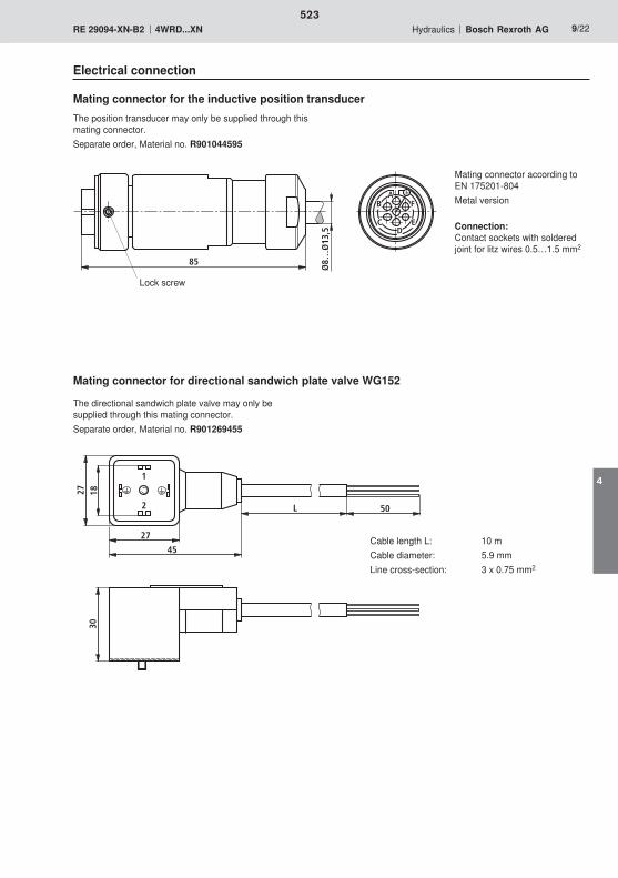
AB
CD
E
F
85
Ø8…
Ø13
,5
2
1
27 18
27
45
30
50L
523
4
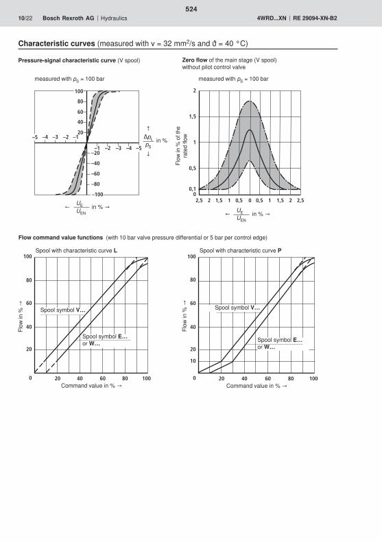
524
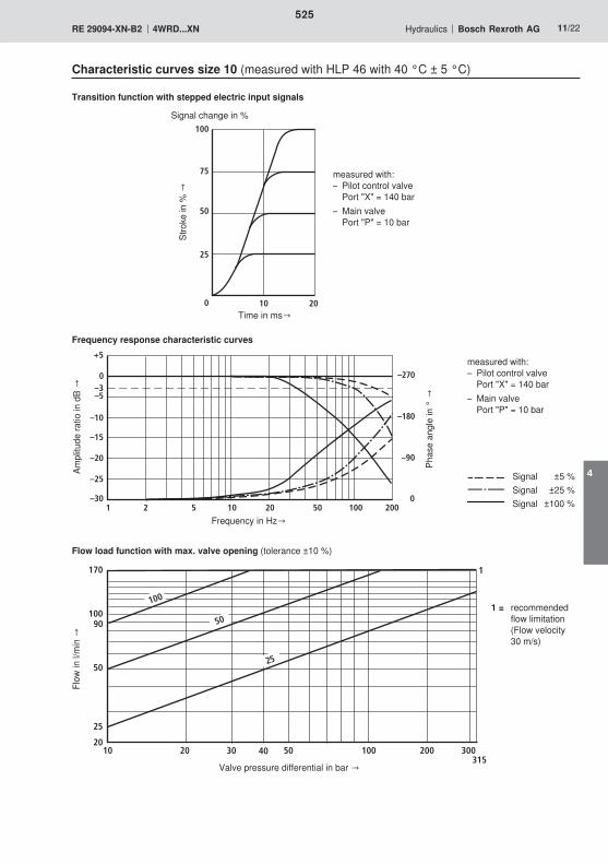
100
75
50
25
0 10 20
525
4
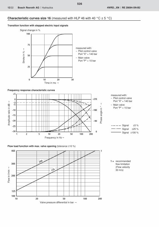
100
75
50
25
0 10 20 30
526
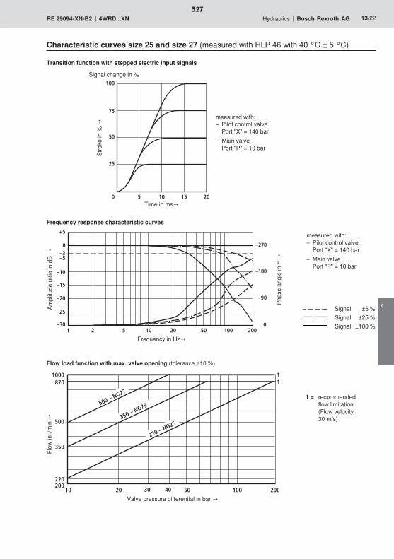
100
75
50
25
0 5 10 15 20
527
4
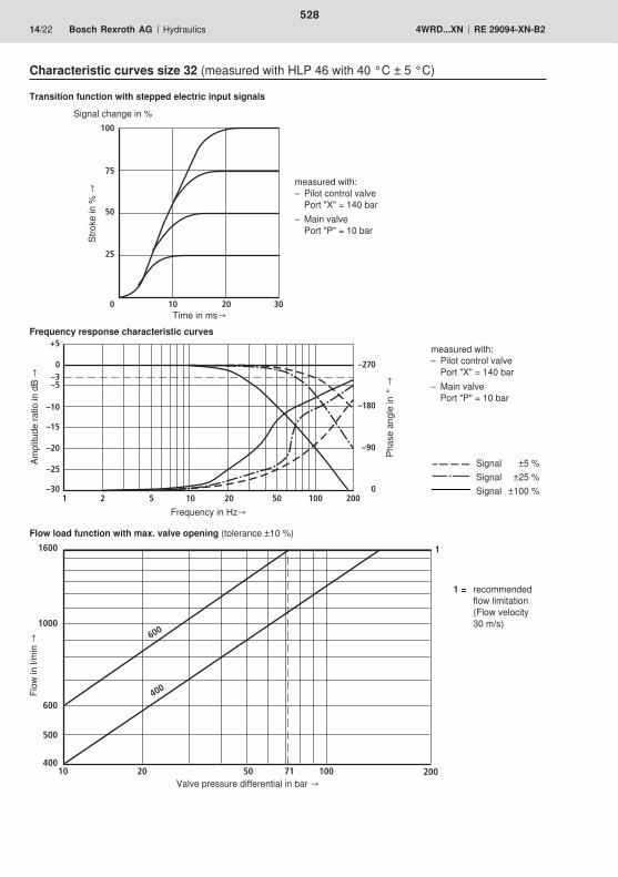
100
75
50
25
0 10 20 30
528
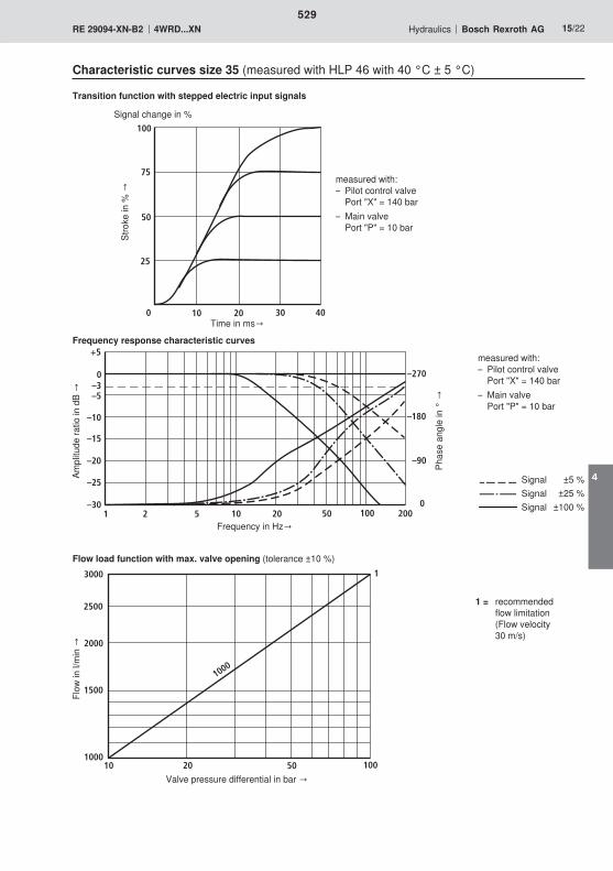
100
25
0 40
50
75
302010
529
4
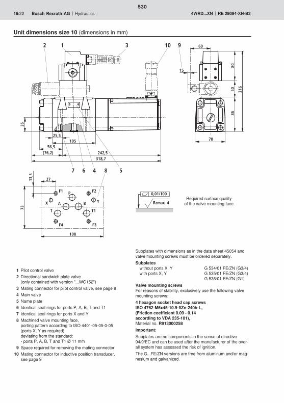
8
9
47 6 5
2 1 3 10
25,5105
318,7
35
86
216
5080
60
15
70
242,5(76,2)56,5
F1 F2P
BA
T1T
F3F4
108
27
73
13,5
YX
0,01/100
Rzmax 4
530
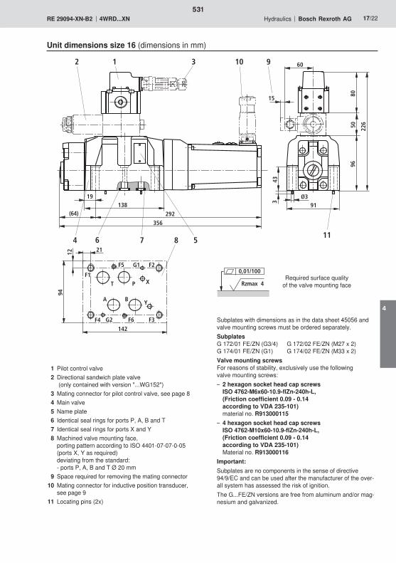
292
356
0,01/100
Rzmax 4
531
4
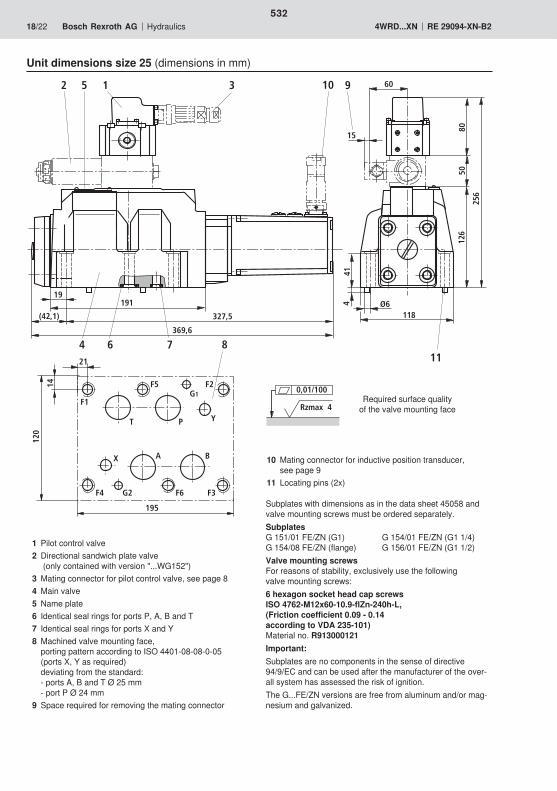
11
9
126
256
50
Ø6
414
80
60
15
118
4 76
2 1 35 10
191
369,6
19
327,5
8
(42,1)
F1
F2
P
BAX
T
F3F4
Y
F5
F6G2
G1
195
21
120
14
0,01/100
Rzmax 4
532
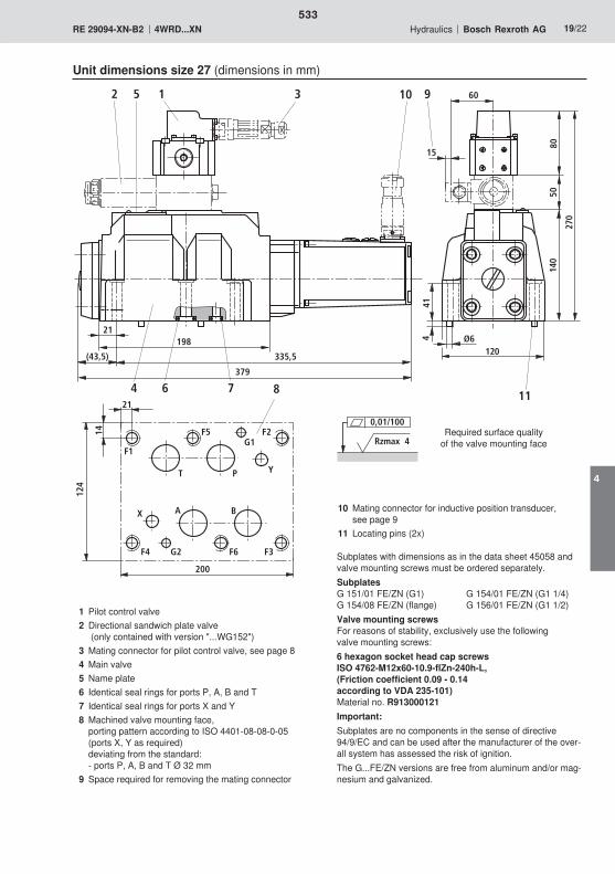
11
9
140
270
50
Ø6
414
80
60
15
120
4 76
2 1 35 10
198
379
21
335,5
8
(43,5)
F1
F2
P
BAX
T
F3F4
Y
F5
F6G2
G1
200
21
124
14
0,01/100
Rzmax 4
533
4
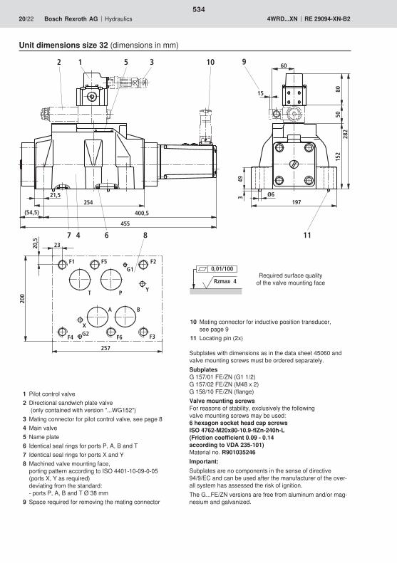
8
5080
60
15
282
152
Ø6
493
197
9
11
21,5254
455
(54,5)
2 1 5 3 10
7 4 6
400,5
F1 F2
P
BA
X
T
F3F4
Y
F5
F6G2
G1
257
23
200
20,5
0,01/100
Rzmax 4
534
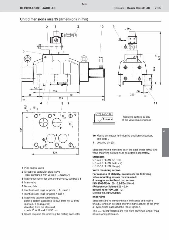
316
539200
370
209
4 7
2 1 3 10
42,7Ø6
704
5
11
88 451
6 8
60
15
9
F1 F2
P
BA
X
T
F3F4
Y
F5
F6G2
G1
320
45
200
20,5
0,01/100
Rzmax 4
535
4

536

537
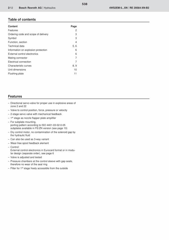
538
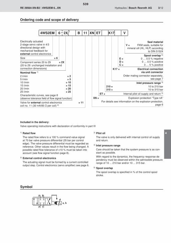
A B
TP
a, b
539
4

A B(T)P
6
3
2
4
5
1
9
8
7
540
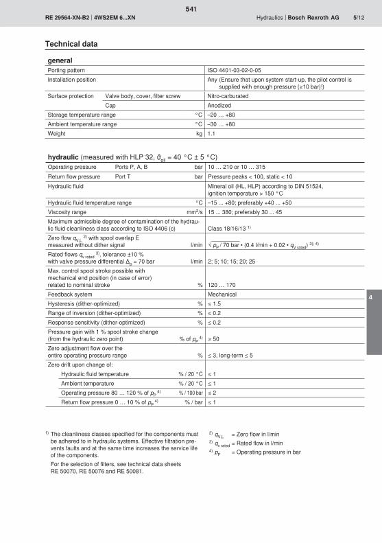
541
4

542

Ø21
,6
58
Ø4,
5...
Ø7,
0
A
B
C
DEF
A B
543
4
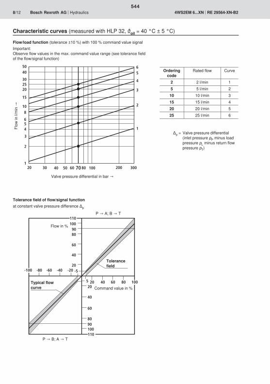
20 30 40 50 80 100 200 300
5040
30
20
15
108
654
3
2
160
1
2
3
4
5
70
6
25
10090
60
80
20
40
20
60
40
1009080
-20-40-60-80
4020 60 80
-5
5
110
-100
100
110
544
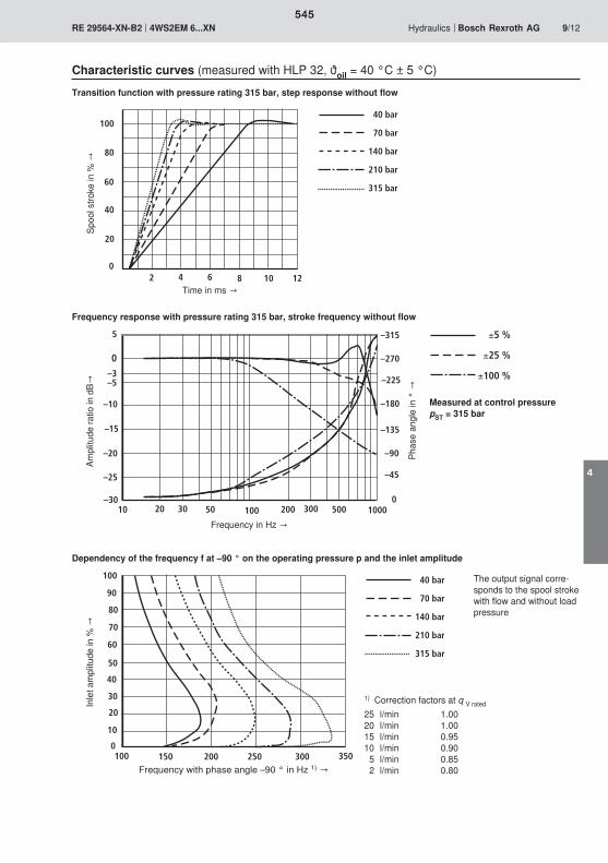
–30
–25
–20
–15
–10
–5
0
5
10 100 10000
–45
–90
–135
–180
–225
–270
–315
50 50020 20030 300
±5 %
±25 %
±100 %–3
100
80
60
40
20
02 4 6 8 10 12
40 bar
70 bar
140 bar
210 bar
315 bar
100 150 200 250 300 3500
100
90
80
70
60
50
40
30
20
10
40 bar
70 bar
140 bar
210 bar
315 bar
545
4
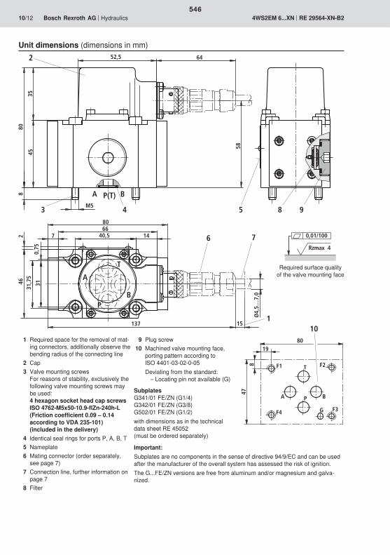
B
52,5 64
M5
58
4535
808
2
4
A P(T)
3
A
BP
T
8066
40,57 14
137
0,75
462
31
Ø4,
5…7,
0
151
6 7
31,7
5
5 8 9
F1
F3F4
F2
G
T
P BA
8019
478
10
0,01/100
Rzmax 4
546
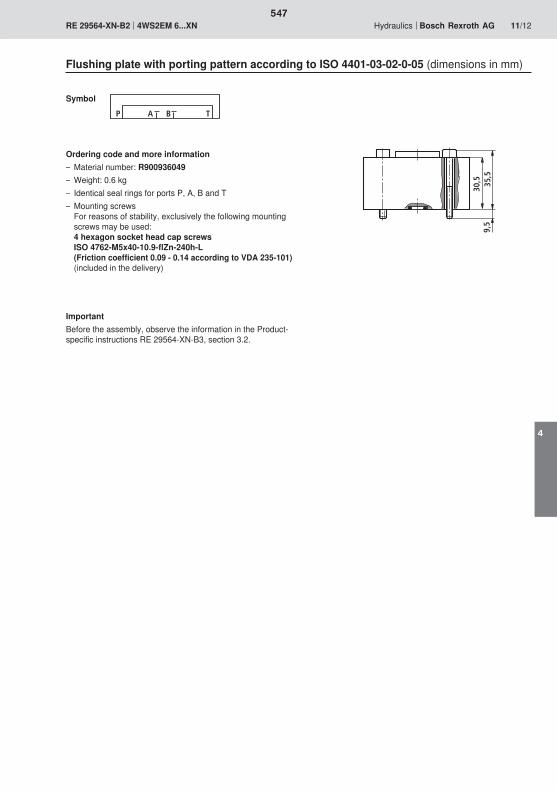
30,5 35
,59,
5
A BP T
547
4

548

549

550
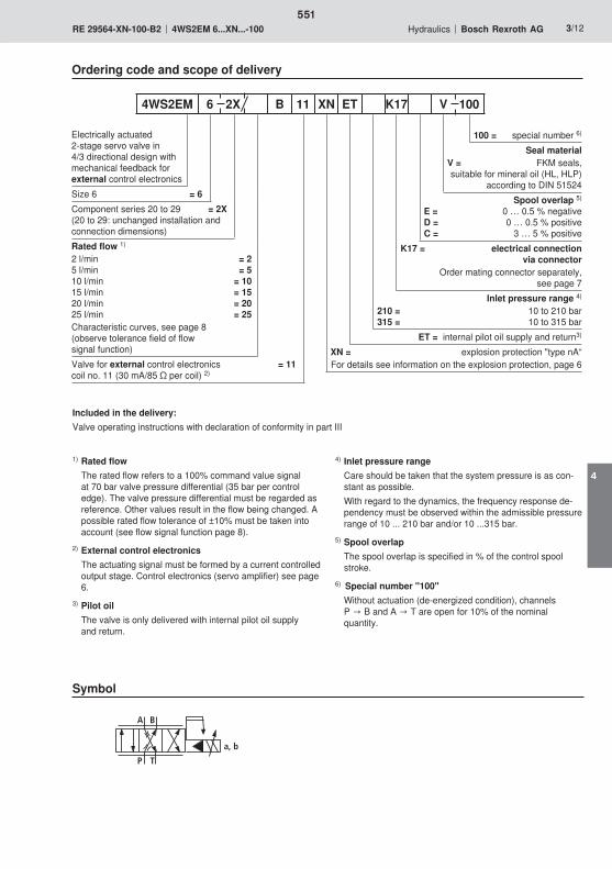
A B
TP
a, b
551
4
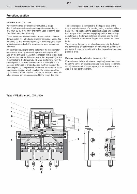
A B(T)P
6
3
2
4
5
1
9
8
7
552
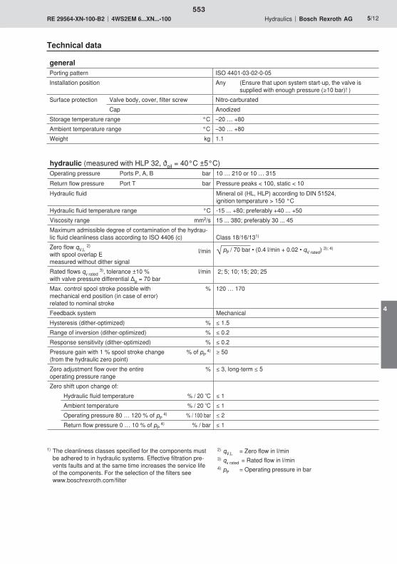
553
4

554

Ø21
,6
58
Ø4,
5...
Ø7,
0
A
B
C
DEF
A B
555
4
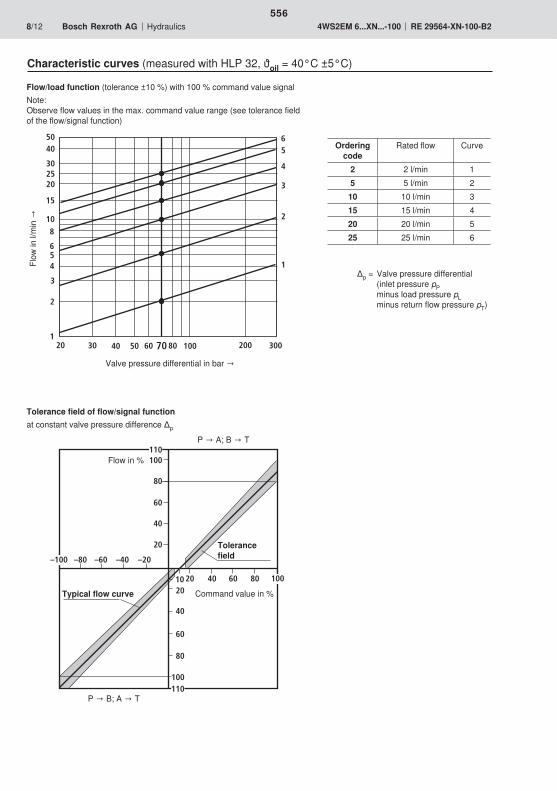
100
60
80
20
40
20
60
40
100
80
–20–40–60–80
4020 60 80
110
–100
100
110
10
20 30 40 50 80 100 200 300
5040
30
20
15
108
654
3
2
160
1
2
3
4
5
70
6
25
556
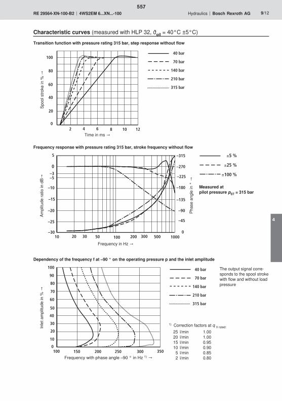
–30
–25
–20
–15
–10
–5
0
5
10 100 10000
–45
–90
–135
–180
–225
–270
–315
50 50020 20030 300
±5 %
±25 %
±100 %–3
100 150 200 250 300 3500
100
90
80
70
60
50
40
30
20
10
40 bar
70 bar
140 bar
210 bar
315 bar
100
80
60
40
20
02 4 6 8 10 12
40 bar
70 bar
140 bar
210 bar
315 bar
557
4

B
52,5 64
M5
58
4535
808
2
4
A P(T)
3
A
BP
T
8066
40,57 14
137
0,75
462
31
Ø4,
5…7,
0
151
6 7
31,7
5
5 8 9
0,01/100
Rzmax 4
F1
F3F4
F2
G
T
P BA
8019
478
10
558
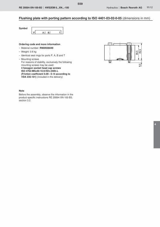
30,5 35
,59,
5
A BP T
559
4

560

561
562

A B
TP
a, b
563
4

A B(T)P
6
3
2
4
5
1
9
8
7
564

565
4
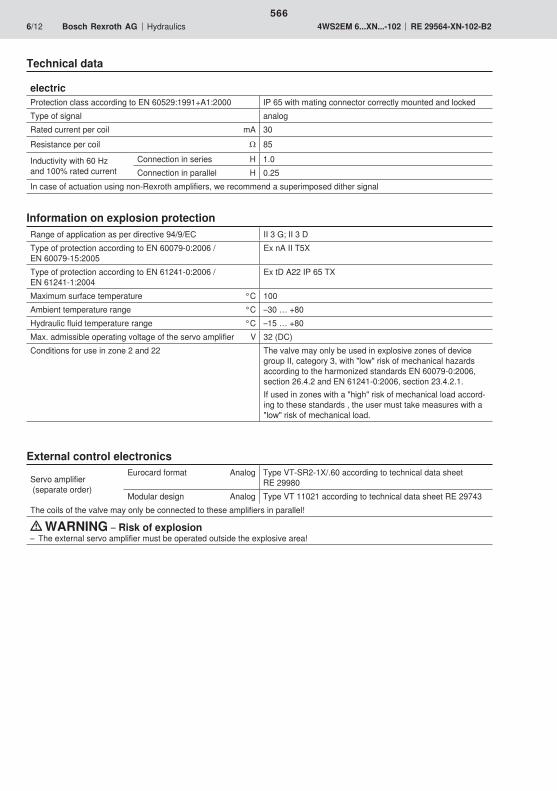
566
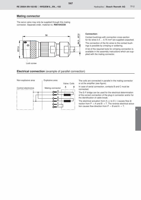
Ø21
,6
58
Ø4,
5...
Ø7,
0
A
B
C
DEF
A B
567
4
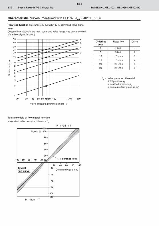
100
60
80
20
40
20
60
40
100
80
–20–40–60–80
4020 60 80
110
–100
100
110
–10
20 30 40 50 80 100 200 300
5040
30
20
15
108
654
3
2
160
1
2
3
4
5
70
6
25
568
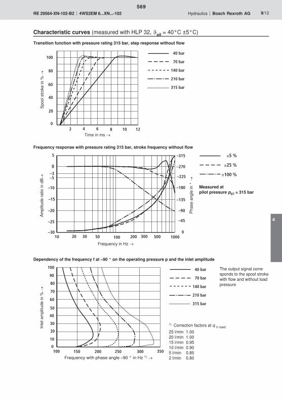
–30
–25
–20
–15
–10
–5
0
5
10 100 10000
–45
–90
–135
–180
–225
–270
–315
50 50020 20030 300
±5 %
±25 %
±100 %–3
100 150 200 250 300 3500
100
90
80
70
60
50
40
30
20
10
40 bar
70 bar
140 bar
210 bar
315 bar
100
80
60
40
20
02 4 6 8 10 12
40 bar
70 bar
140 bar
210 bar
315 bar
569
4
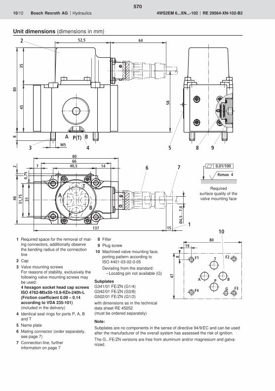
B
52,5 64
M5
58
4535
808
2
4
A P(T)
3
A
BP
T
8066
40,57 14
137
0,75
462
31
Ø4,
5…7,
0
151
6 7
31,7
5
5 8 9
0,01/100
Rzmax 4
F1
F3F4
F2
G
T
P BA
8019
478
10
570

30,5 35
,59,
5
A BP T
571
4

572

573

574
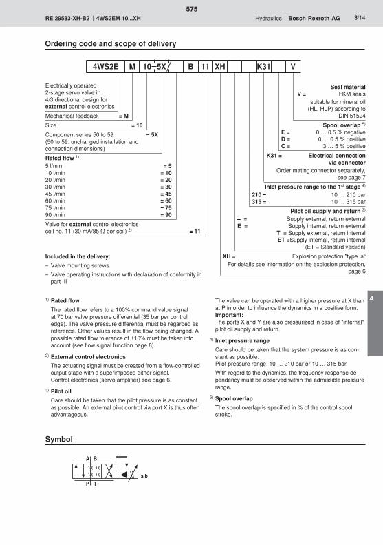
�
��
�
���
575
4

�
�
�
�
�
�
�
�
�
�
�
576
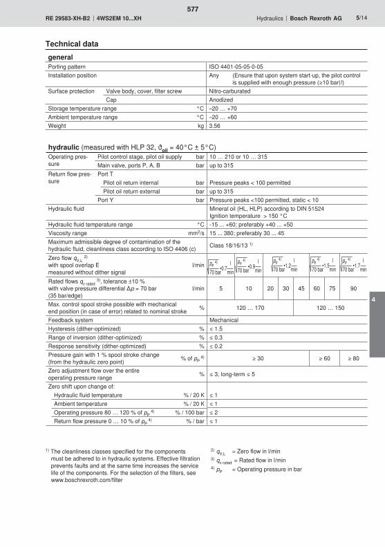
577
4
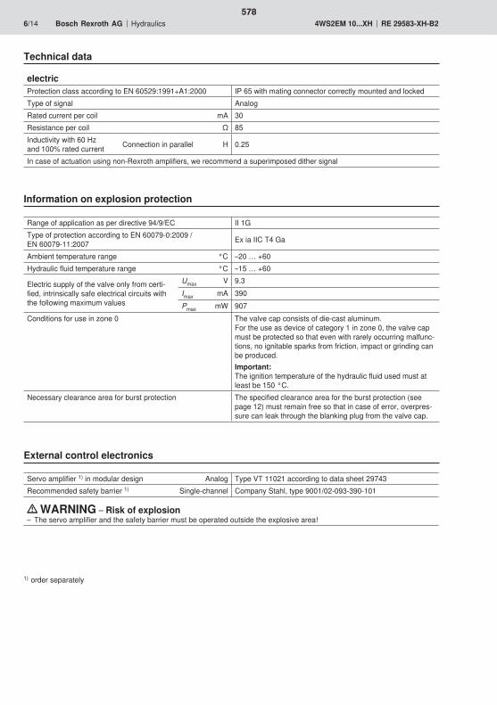
578
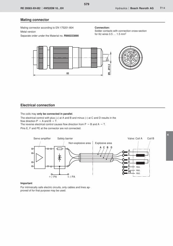
� ���
� �
�
����
��������
�
�
�����
��
��
�
�
�������
��
579
4
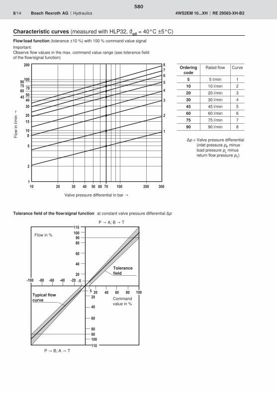
����
�
��
��
�
��
�
�
������
���� ������
��� � ��
��
�
�
���
��
�
�
�
��
��
�
��
��
��
���
�
�
�
��
����� ���� � ��� �����
�
�
�
������
�
580

�
����� ������������
�� �� ��� ��� ��� �����
<��
<�
<��
<�
<��
<
�
�� ��� 2���
<
<1�
<��
<�3�
<��
<�2�
<��
� ���� ���
<�
� �
�
�
��
��
�
��
�
��
��
��
�
��
� ��
�
�
��
��
�
��
��
��
��
�
��
<��
<�
<��
<�
<��
<
�
�� ��� 2���
<
<1�
<��
<�3�
<��
<�2�
<��
� ���� ���
<�
�
����� ������������
�� �� �� ��� ��� ��� ���
581
4

� ��
�
�
��
��
�
��
�� �
��
��
��
�
��
� ��
�
�
��
��
�
��
�� �
��
��
��
�
��
�� �� ��
���
���
��
��
��
�
�
��� ���
���
���
��������
���������
��
� � �� � ���
<�
<��
<�
<��
<
�
��� 2��
<��
<���<1�
<0�<��
��������<��
<�
�
�
����� ������������
�� �� �� ��� ��� ��� ��� �
����� ������������
�� �� �� ��� ��� ��� ���
582
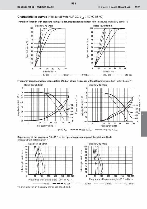
� ��
�
�
��
��
�
��
��
��
��
��
�
��
�� � � ��
�
�
��
��
�
��
��
��
��
��
�
��
� � ��
� �� � ���
<�
<��
<�
<��
<
�
2��
<��<���
<1�<0�<��
���<��
����
<�
�� �� � ���
<�
<��
<�
<��
<
�
��� 2��
<��
<���
<1�<0�<��
�������<��
<�
�
����� ������������
�� �� �� ��� ��� ��� ��� �
����� ������������
�� �� �� ��� ��� ��� ���
583
4

��� �
���
��
� ��
��
�
� � ����
���
����
���
�
� �
��
!"
�� ��
��
�
#$���
�
� ���
���
���
��
����
�
�
�
" !
0,01/100
Rzmax 4
584

���
���
��
� � " � � ! �
585
4

586

587
588

A B
TP
a, b
589
4
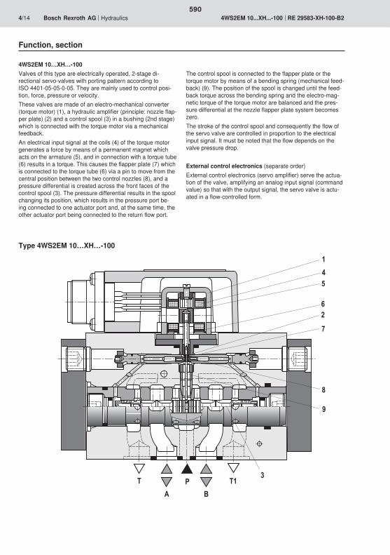
�
�
�
�
�
�
�
�
�
�
�
590

591
4
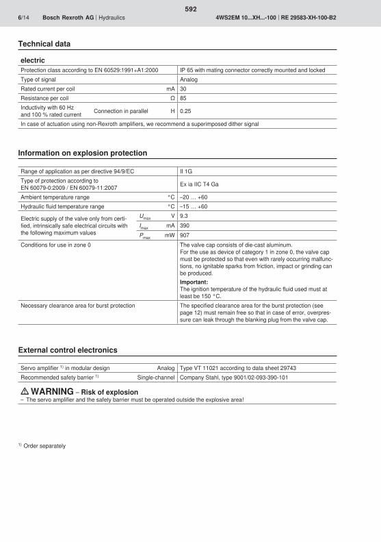
592
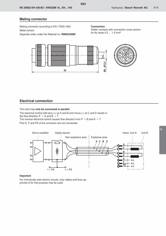
� ���
� �
�
����
��������
�
�
�����
��
��
�
�
�������
��
593
4

���
0�
3�
��
�
��
0�
�
���
3�
!��!�!0�!3�
��� 0� 3�
���
!���
���
���
��
�
�
��
��
�
��
��
��
���
�
�
�
��
����� ���� � ��� �����
�
�
�
������
�
594

�
����� ������������
�� �� ��� ��� ��� �����
<��
<�
<��
<�
<��
<
�
�� ��� 2���
<
<1�
<��
<�3�
<��
<�2�
<��
� ���� ���
<�
� �
�
�
��
��
�
��
�
��
��
��
�
��
� ��
�
�
��
��
�
��
��
��
��
�
��
<��
<�
<��
<�
<��
<
�
�� ��� 2���
<
<1�
<��
<�3�
<��
<�2�
<��
� ���� ���
<�
�
����� ������������
�� �� �� ��� ��� ��� ���
595
4
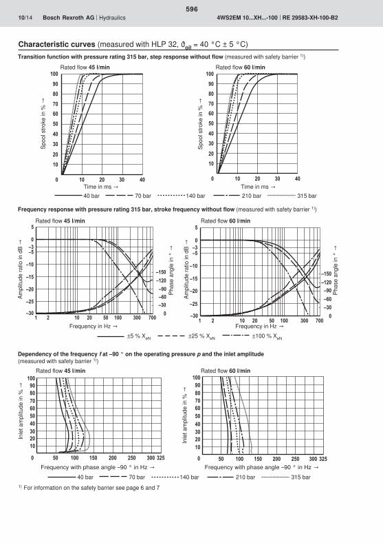
� ��
�
�
��
��
�
��
�� �
��
��
��
�
��
� ��
�
�
��
��
�
��
�� �
��
��
��
�
��
�� �� ��
���
���
��
��
��
�
�
��� ���
���
���
��������
���������
��
� � �� � ���
<�
<��
<�
<��
<
�
��� 2��
<��
<���<1�
<0�<��
��������<��
<�
�
�
����� ������������
�� �� �� ��� ��� ��� ��� �
����� ������������
�� �� �� ��� ��� ��� ���
596

� ��
�
�
��
��
�
��
��
��
��
��
�
��
�� � � ��
�
�
��
��
�
��
��
��
��
��
�
��
� � ��
� �� � ���
<�
<��
<�
<��
<
�
2��
<��<���
<1�<0�<��
���<��
����
<�
�� �� � ���
<�
<��
<�
<��
<
�
��� 2��
<��
<���
<1�<0�<��
�������<��
<�
�
����� ������������
�� �� �� ��� ��� ��� ��� �
����� ������������
�� �� �� ��� ��� ��� ���
597
4
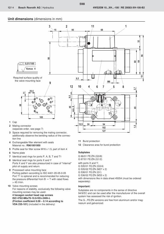
��� �
���
��
� ��
��
�
� � ����
���
����
���
�
� �
��
!"
�� ��
��
�
#$���
�
� ���
���
���
��
����
�
�
�
" !
0,01/100
Rzmax 4
598

���
���
��
� � " � � ! �
599
4

600

601

602

� '
$�
5)�8
603
4
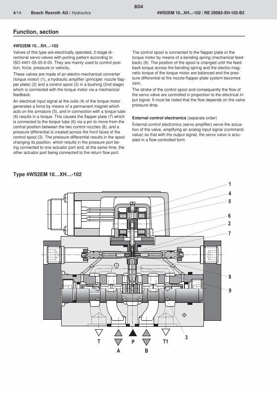
�
�
�
�
�
�
�
�
�
�
�
604
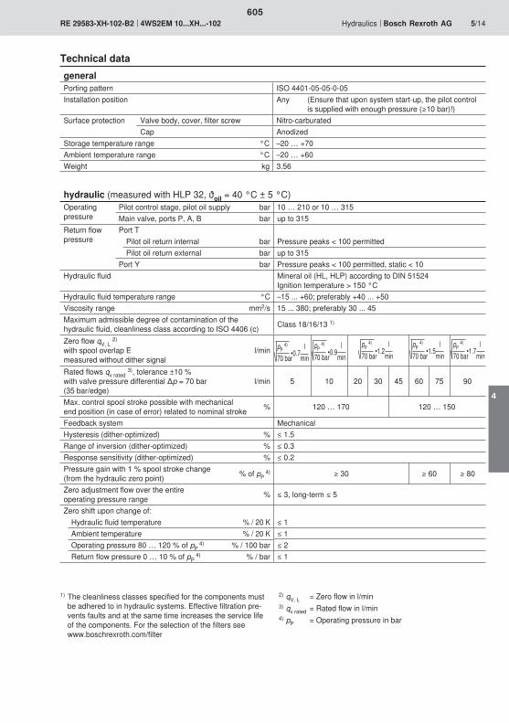
605
4

606

� ���
� �
�
����
��������
�
�
�����
��
��
�
�
�������
��
607
4
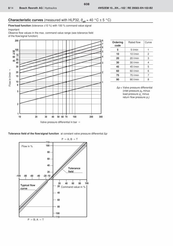
���
0�
3�
��
�
��
0�
�
���
3�
!��!�!0�!3�
��� 0� 3�
���
!���
���
���
!��
�
�
��
��
�
��
��
��
���
�
�
�
��
����� ���� � ��� �����
�
�
�
������
�
608

�
����� ������������
�� �� ��� ��� ��� �����
<��
<�
<��
<�
<��
<
�
�� ��� 2���
<
<1�
<��
<�3�
<��
<�2�
<��
� ���� ���
<�
� �
�
�
��
��
�
��
�
��
��
��
�
��
� ��
�
�
��
��
�
��
��
��
��
�
��
<��
<�
<��
<�
<��
<
�
�� ��� 2���
<
<1�
<��
<�3�
<��
<�2�
<��
� ���� ���
<�
�
����� ������������
�� �� �� ��� ��� ��� ���
609
4

� ��
�
�
��
��
�
��
�� �
��
��
��
�
��
� ��
�
�
��
��
�
��
�� �
��
��
��
�
��
�� �� ��
���
���
��
��
��
�
�
��� ���
���
���
��������
���������
��
� � �� � ���
<�
<��
<�
<��
<
�
��� 2��
<��
<���<1�
<0�<��
��������<��
<�
�
�
����� ������������
�� �� �� ��� ��� ��� ��� �
����� ������������
�� �� �� ��� ��� ��� ���
610

� ��
�
�
��
��
�
��
��
��
��
��
�
��
�� � � ��
�
�
��
��
�
��
��
��
��
��
�
��
� � ��
� �� � ���
<�
<��
<�
<��
<
�
2��
<��<���
<1�<0�<��
���<��
����
<�
�� �� � ���
<�
<��
<�
<��
<
�
��� 2��
<��
<���
<1�<0�<��
�������<��
<�
�
����� ������������
�� �� �� ��� ��� ��� ��� �
����� ������������
�� �� �� ��� ��� ��� ���
611
4
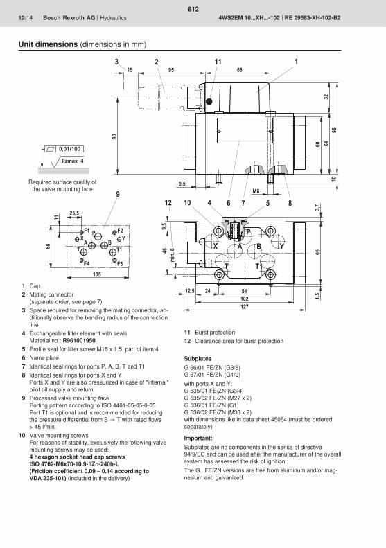
��� �
���
��
� ��
��
�
� � ����
���
����
���
�
� �
��
!"
�� ��
��
�
#$���
�
� ���
���
���
��
����
�
�
�
" !
0,01/100
Rzmax 4
612

���
���
��
� � " � � ! �
613
4

614
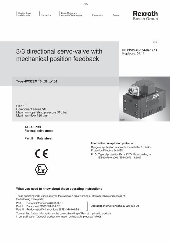
615
616

� '
$�
5)�8
617
4
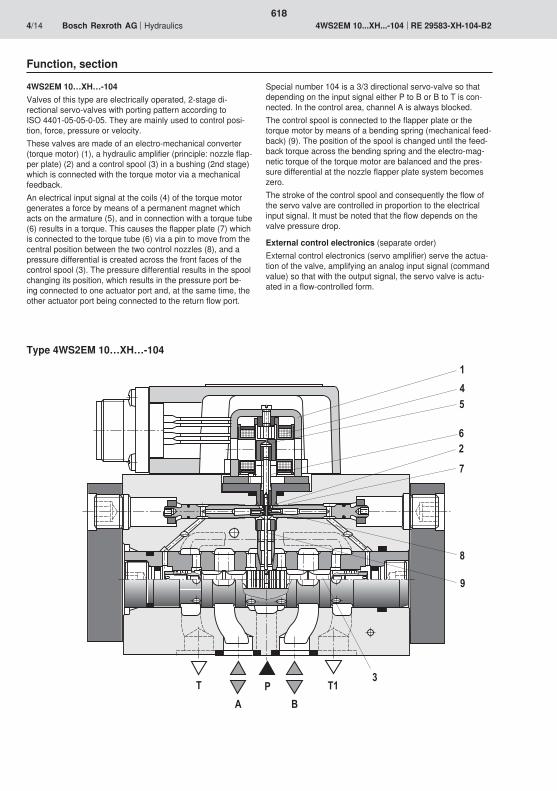
�
�
�
�
�
�
�
�
�
�
�
618
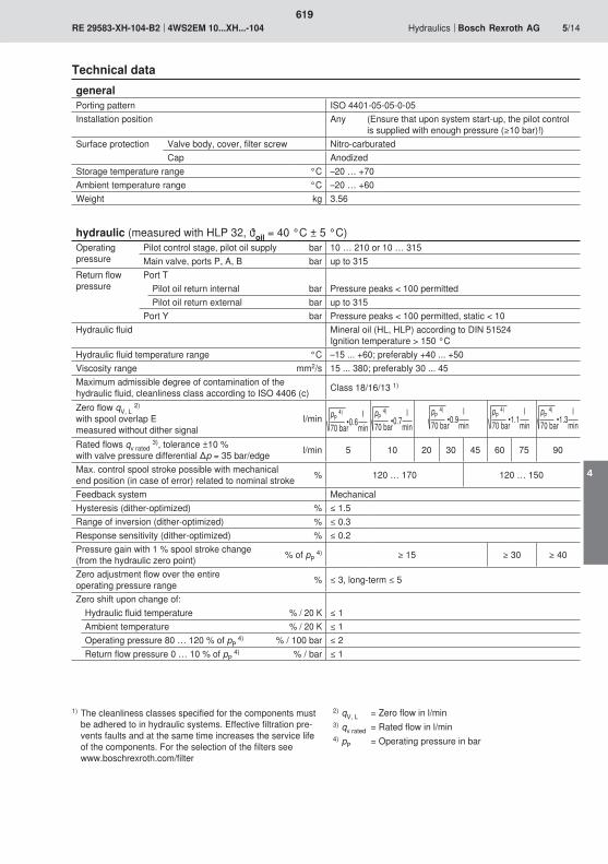
619
4

620
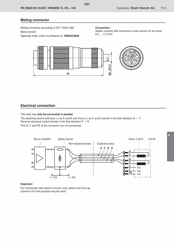
� ���
� �
�
����
��������
�
�
�����
��
��
�
�
�������
��
621
4
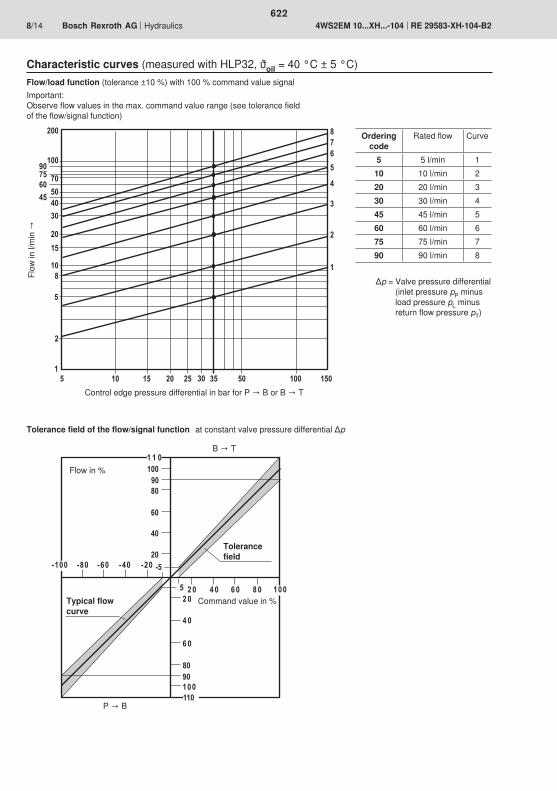
���1�
0�
3�
��
�
��
0�
�
���1�3�
!��!�!0�!3�
��� 0� 3�
!
� � �
!���
���
���
��
��
��
�
2�
���
�
���
�
�
�
023
��� ���� ��� ����
�
3
�
0�21�
��
622

�
����� ������������
�� �� ��� ��� ��� �����
<��
<�
<��
<�
<��
<
�
�� ��� 2���
<
<1�
<��
<�3�
<��
<�2�
<��
� ���� ���
<�
� �
�
�
��
��
�
��
�
��
��
��
�
��
� ��
�
�
��
��
�
��
��
��
��
�
��
<��
<�
<��
<�
<��
<
�
�� ��� 2���
<
<1�
<��
<�3�
<��
<�2�
<��
� ���� ���
<�
�
����� ������������
�� �� �� ��� ��� ��� ���
623
4

� ��
�
�
��
��
�
��
�� �
��
��
��
�
��
� ��
�
�
��
��
�
��
�� �
��
��
��
�
��
�� �� ��
���
���
��
��
��
�
�
��� ���
���
���
��������
���������
��
� � �� � ���
<�
<��
<�
<��
<
�
��� 2��
<��
<���<1�
<0�<��
��������<��
<�
�
�
����� ������������
�� �� �� ��� ��� ��� ��� �
����� ������������
�� �� �� ��� ��� ��� ���
624

� ��
�
�
��
��
�
��
��
��
��
��
�
��
�� � � ��
�
�
��
��
�
��
��
��
��
��
�
��
� � ��
� �� � ���
<�
<��
<�
<��
<
�
2��
<��<���
<1�<0�<��
���<��
����
<�
�� �� � ���
<�
<��
<�
<��
<
�
��� 2��
<��
<���
<1�<0�<��
�������<��
<�
�
����� ������������
�� �� �� ��� ��� ��� ��� �
����� ������������
�� �� �� ��� ��� ��� ���
625
4
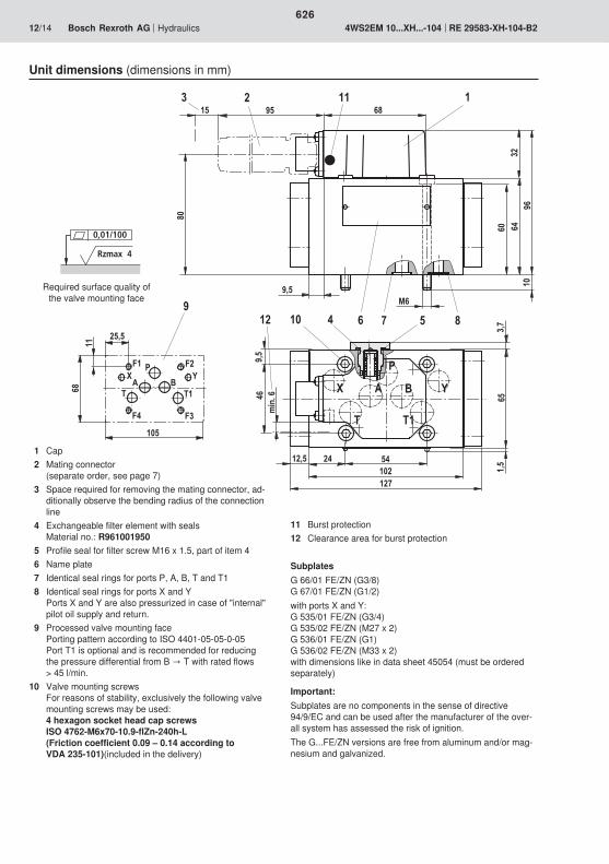
��� �
���
��
� ��
��
�
� � ����
���
����
���
�
� �
��
!"
�� ��
��
�
#$���
�
� ���
���
���
��
����
�
�
�
" !
0,01/100
Rzmax 4
626
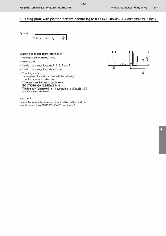
���
���
��
� � " � � ! �
627
4

628

629

630
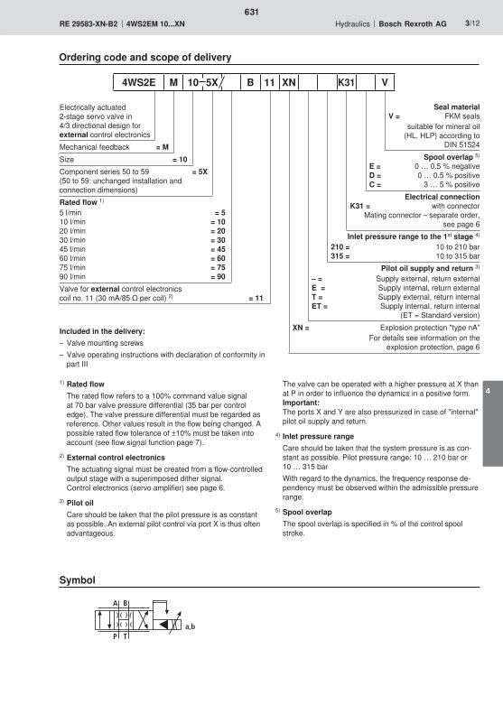
A
TP
B
a,b
631
4

T
AP
B
T1
6
3
2
45
1
9
7
8
632
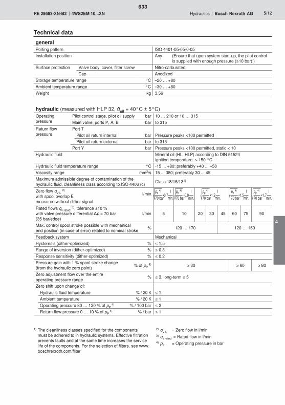
633
4
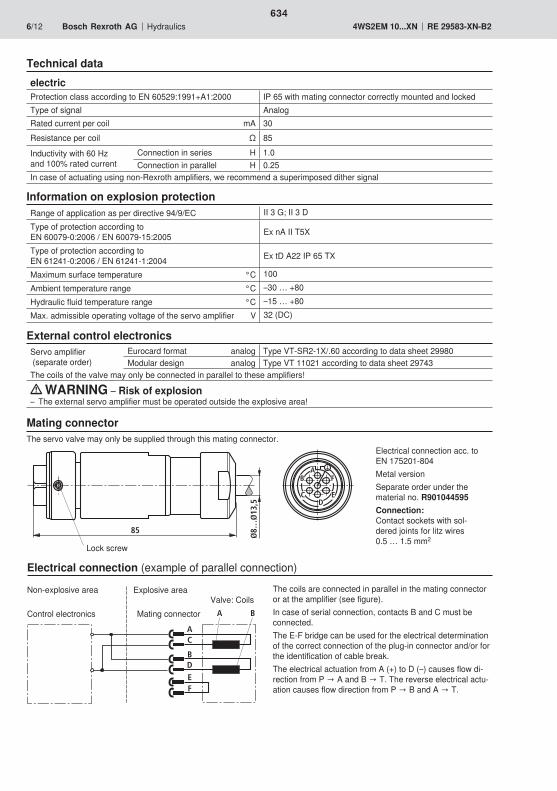
A
B
C
DEF
A B
AB
CD
E
F
85
Ø8…
Ø13
,5
634
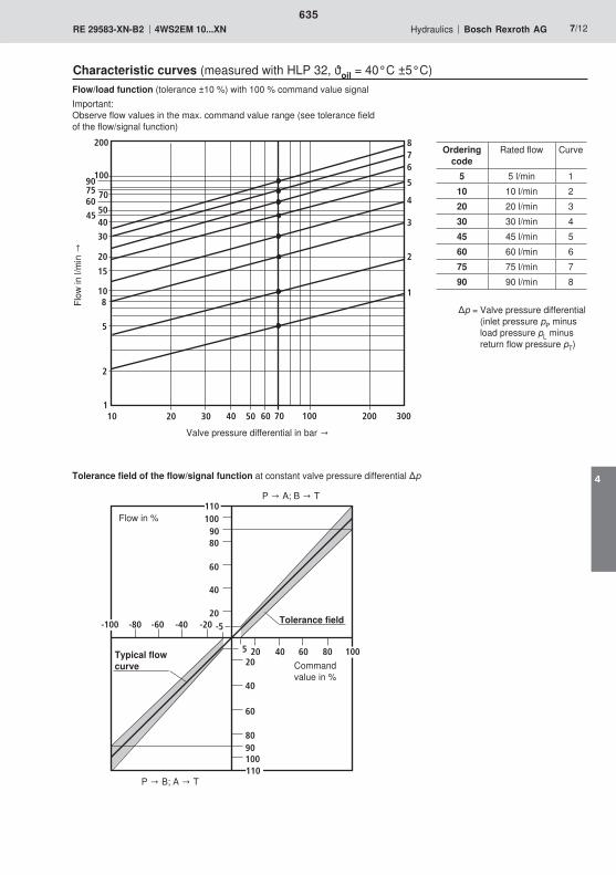
5
10
20
30
40
70
100
50
200
1
2
3
4
5
678
302010 705040 200 3001001
2
8
15
45
607590
60
10090
60
80
20
40
20
60
40
1009080
-20-40-60-80
4020 60 80
-5
5
110
-100
100
110
635
4
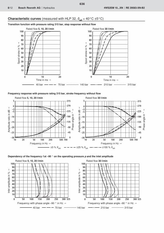
0
102030405060708090
100
50 100 150 200 250 300 325
–30
–25
–20
–15
–10
–5
0
5
10 100 7000
–45
–90
–135
–180
–225
–270
–315
50 50020 200
–3
0 20
40
60
80
100
10
20
30
50
70
10
90
0 20
40
60
80
100
10
20
30
50
70
10
90
–30
–25
–20
–15
–10
–5
0
5
10 100 7000
–45
–90
–135
–180
–225
–270
–315
50 50020 200
–3
0
102030405060708090
100
50 100 150 200 250 300 325
636
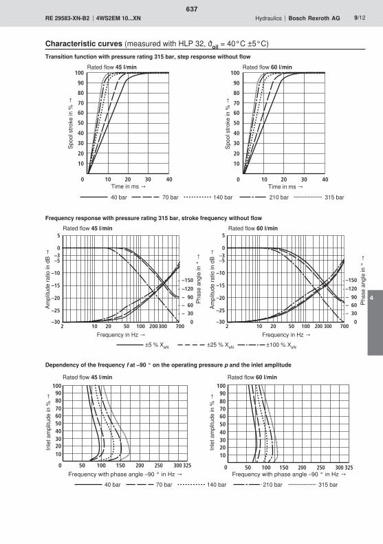
0 20
40
60
80
100
10
20
30 40
30
50
70
10
90
0 20
40
60
80
100
10
20
30 40
30
50
70
10
90
2 20 50 100
–25
–20
–15
–10
–5
0
5
300 700
–150
–120
– 90– 60
– 30
10 0–30
200
–3
2 20 50 100
–25
–20
–15
–10
–5
0
5
300 700
–150
–120
– 90– 60
– 30
10 0–30
200
–3
0
102030405060708090
100
50 100 150 200 250 300 325 0
102030405060708090
100
50 100 150 200 250 300 325
637
4
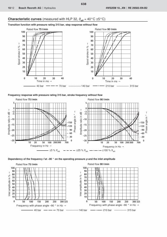
0 30
40
60
80
100
10
20
20
30
50
70
10
90
40 0 30
40
60
80
100
10
20
20
30
50
70
10
90
40
2 20 50 100
–25
–20
–15
–10
–5
0
5
300 700
–150
–120
– 90– 60
– 30
10 0–30
200
–3
2 20 50 100
–25
–20
–15
–10
–5
0
5
300 700
–150
–120
–90–60
–30
100–30
200
–3
0
102030405060708090
100
50 100 150 200 250 300 325 0
102030405060708090
100
50 100 150 200 250 300 325
638

9515 68
9,5M6
80
60 6432
9610
3 1
5424102127
12,5
46
653,
7
9,5
P
A B
T1T
YX
57 810
1,5
6
2
4
F1 F2P
BAT
F3F4
105
25,5
6811
T1
9
X Y
0,01/100
Rzmax 4
639
4

9,5
40,5
46,5
T P X A B Y T1
640

641

642
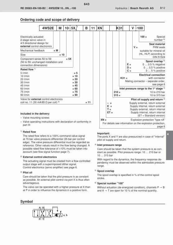
A B
TP
a, b
643
4
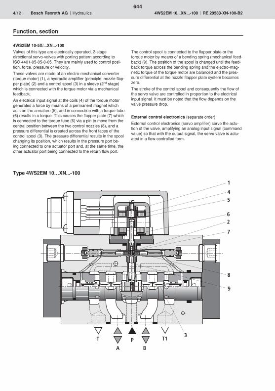
T
AP
B
T1
6
3
2
45
1
9
7
8
644

645
4
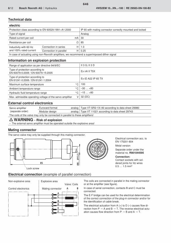
A
B
C
DEF
A B
AB
CD
E
F
85
Ø8…
Ø13
,5
646
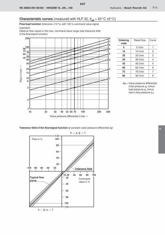
5
10
20
30
40
70
100
50
200
1
2
3
4
5
678
302010 705040 200 3001001
2
8
15
45
607590
60
100
60
80
20
40
20
60
40
100
80
-20-40-60-80
4020 60 80
110
-100
100
110
10
647
4

0
102030405060708090
100
50 100 150 200 250 300 325
–30
–25
–20
–15
–10
–5
0
5
10 100 7000
–45
–90
–135
–180
–225
–270
–315
50 50020 200
–3
0 20
40
60
80
100
10
20
30
50
70
10
90
0 20
40
60
80
100
10
20
30
50
70
10
90
–30
–25
–20
–15
–10
–5
0
5
10 100 7000
–45
–90
–135
–180
–225
–270
–315
50 50020 200
–3
0
102030405060708090
100
50 100 150 200 250 300 325
648

0 20
40
60
80
100
10
20
30 40
30
50
70
10
90
0 20
40
60
80
100
10
20
30 40
30
50
70
10
90
2 20 50 100
–25
–20
–15
–10
–5
0
5
300 700
–150
–120
– 90– 60
– 30
10 0–30
200
–3
2 20 50 100
–25
–20
–15
–10
–5
0
5
300 700
–150
–120
– 90– 60
– 30
10 0–30
200
–3
0
102030405060708090
100
50 100 150 200 250 300 325 0
102030405060708090
100
50 100 150 200 250 300 325
649
4
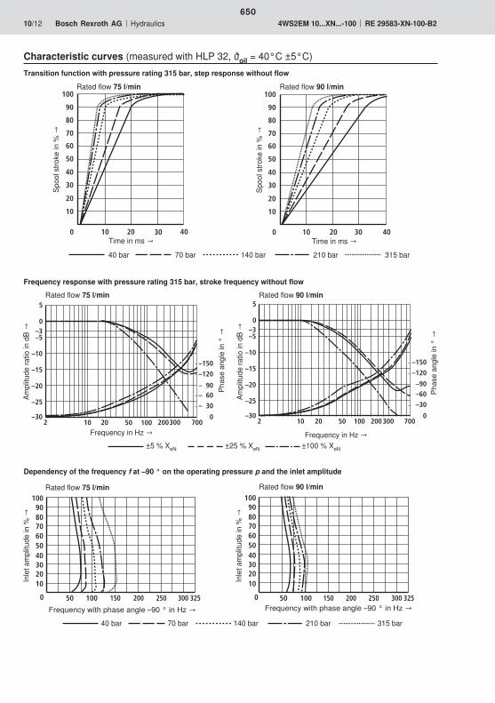
0 30
40
60
80
100
10
20
20
30
50
70
10
90
40 0 30
40
60
80
100
10
20
20
30
50
70
10
90
40
2 20 50 100
–25
–20
–15
–10
–5
0
5
300 700
–150
–120
– 90– 60
– 30
10 0–30
200
–3
2 20 50 100
–25
–20
–15
–10
–5
0
5
300 700
–150
–120
–90–60
–30
100–30
200
–3
0
102030405060708090
100
50 100 150 200 250 300 325 0
102030405060708090
100
50 100 150 200 250 300 325
650

9515 68
9,5M6
80
60 6432
9610
3 1
5424102127
12,5
46
653,
7
9,5
P
A B
T1T
YX
57 810
1,5
6
2
4
F1 F2P
BAT
F3F4
105
25,5
6811
T1
9
X Y
0,01/100
Rzmax 4
651
4

9,5
40,5
46,5
T P X A B Y T1
652

653
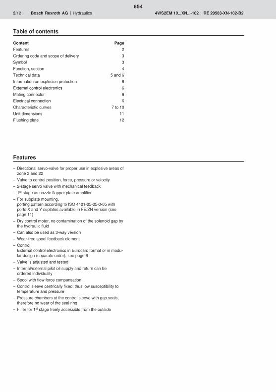
654
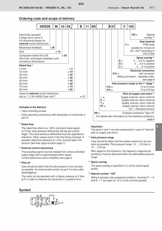
A B
TP
a, b
655
4

T
AP
B
T1
6
3
2
45
1
9
7
8
656

657
4
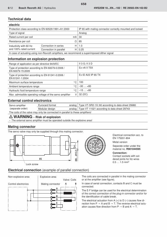
A
B
C
DEF
A B
AB
CD
E
F
85
Ø8…
Ø13
,5
658
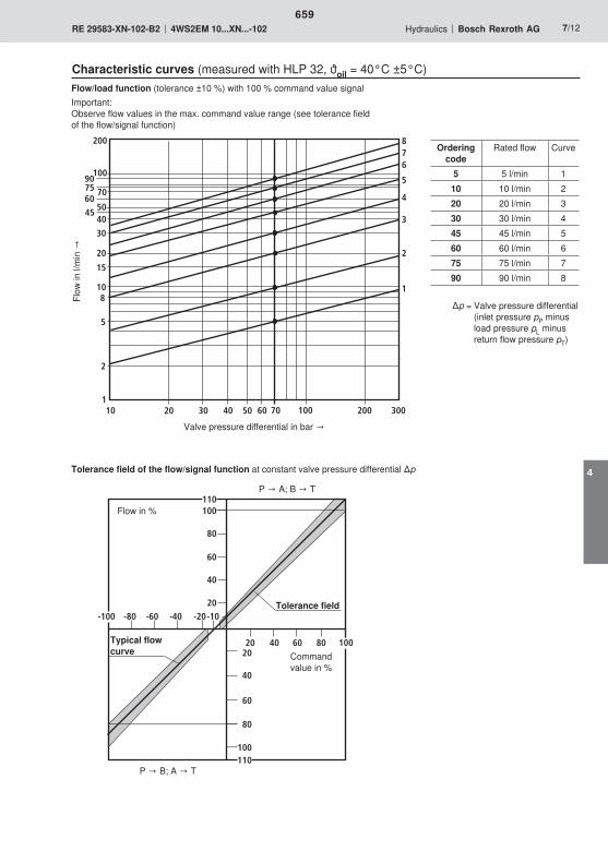
5
10
20
30
40
70
100
50
200
1
2
3
4
5
678
302010 705040 200 3001001
2
8
15
45
607590
60
100
60
80
20
40
20
60
40
100
80
-20-40-60-80
4020 60 80
110
-100
100
110
-10
659
4
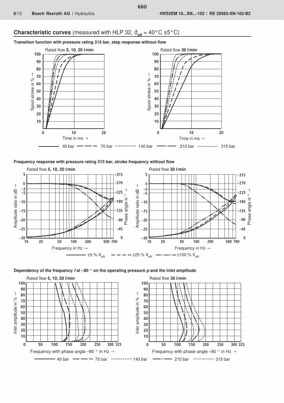
0
102030405060708090
100
50 100 150 200 250 300 325
–30
–25
–20
–15
–10
–5
0
5
10 100 7000
–45
–90
–135
–180
–225
–270
–315
50 50020 200
–3
0 20
40
60
80
100
10
20
30
50
70
10
90
0 20
40
60
80
100
10
20
30
50
70
10
90
–30
–25
–20
–15
–10
–5
0
5
10 100 7000
–45
–90
–135
–180
–225
–270
–315
50 50020 200
–3
0
102030405060708090
100
50 100 150 200 250 300 325
660
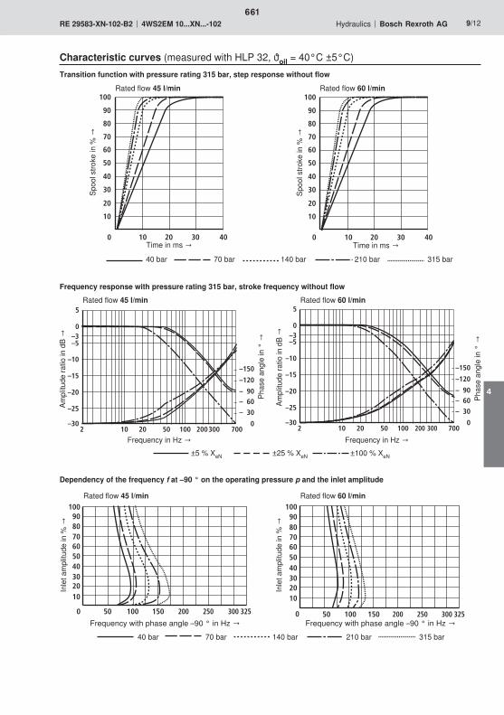
0 20
40
60
80
100
10
20
30 40
30
50
70
10
90
0 20
40
60
80
100
10
20
30 40
30
50
70
10
90
2 20 50 100
–25
–20
–15
–10
–5
0
5
300 700
–150
–120
– 90– 60
– 30
10 0–30
200
–3
2 20 50 100
–25
–20
–15
–10
–5
0
5
300 700
–150
–120
– 90– 60
– 30
10 0–30
200
–3
0
102030405060708090
100
50 100 150 200 250 300 325 0
102030405060708090
100
50 100 150 200 250 300 325
661
4

0 30
40
60
80
100
10
20
20
30
50
70
10
90
40 0 30
40
60
80
100
10
20
20
30
50
70
10
90
40
2 20 50 100
–25
–20
–15
–10
–5
0
5
300 700
–150
–120
– 90– 60
– 30
10 0–30
200
–3
2 20 50 100
–25
–20
–15
–10
–5
0
5
300 700
–150
–120
–90–60
–30
100–30
200
–3
0
102030405060708090
100
50 100 150 200 250 300 325 0
102030405060708090
100
50 100 150 200 250 300 325
662

9515 68
9,5M6
80
60 6432
9610
3 1
5424102127
12,5
46
653,
7
9,5
P
A B
T1T
YX
57 810
1,5
6
2
4
F1 F2P
BAT
F3F4
105
25,5
6811
T1
9
X Y
0,01/100
Rzmax 4
663
4

9,5
40,5
46,5
T P X A B Y T1
664

665

666
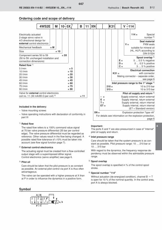
A B
TP
a, b
667
4
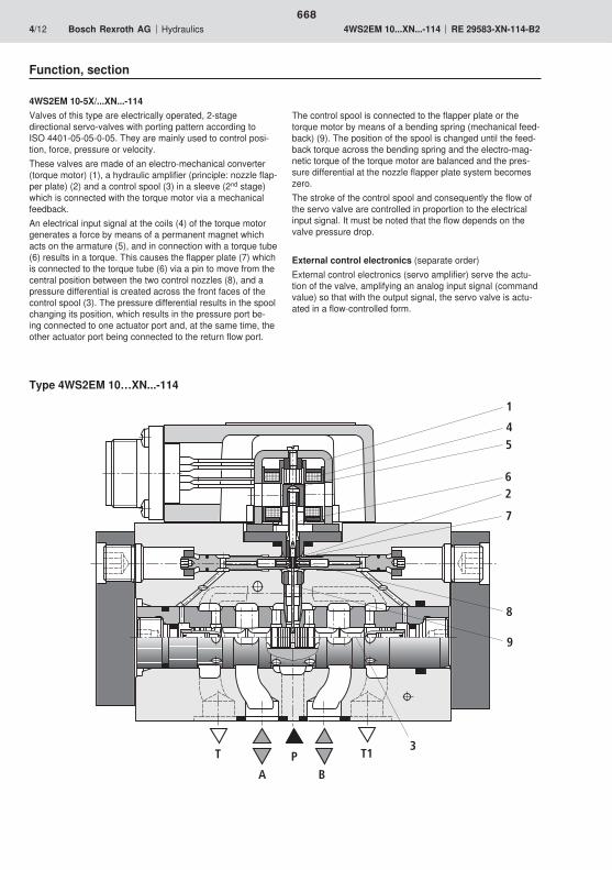
T
AP
B
T1
6
3
2
45
1
9
7
8
668
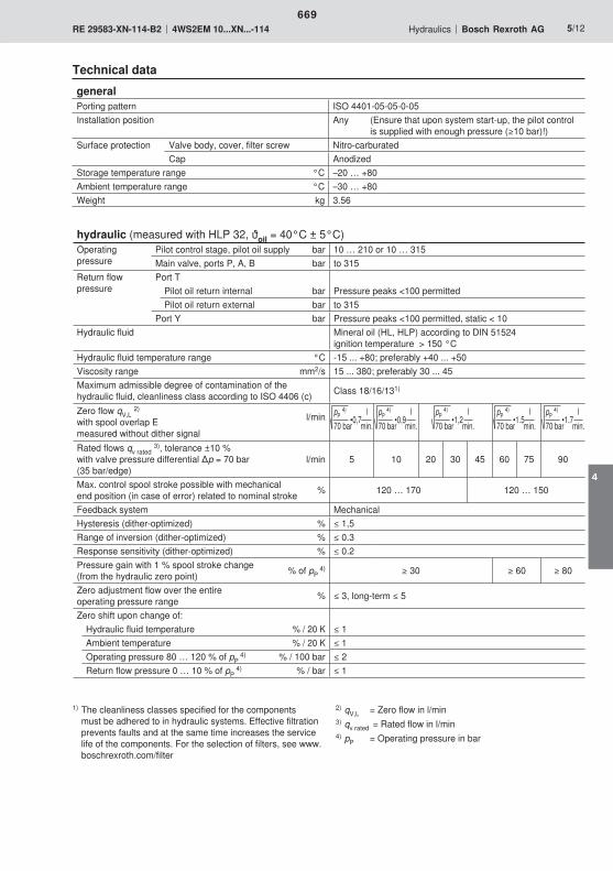
669
4
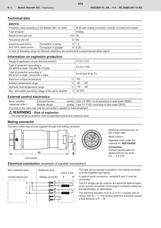
A
B
C
DEF
A B
AB
CD
E
F
85
Ø8…
Ø13
,5
670

5
10
20
30
40
70
100
50
200
1
2
3
4
5
678
302010 705040 200 3001001
2
8
15
45
607590
60
100
60
80
20
40
20
60
40
100
80
-20-40-60-80
4020 60 80
110
-100
100
110
-10
671
4

0
102030405060708090
100
50 100 150 200 250 300 325
–30
–25
–20
–15
–10
–5
0
5
10 100 7000
–45
–90
–135
–180
–225
–270
–315
50 50020 200
–3
0 20
40
60
80
100
10
20
30
50
70
10
90
0 20
40
60
80
100
10
20
30
50
70
10
90
–30
–25
–20
–15
–10
–5
0
5
10 100 7000
–45
–90
–135
–180
–225
–270
–315
50 50020 200
–3
0
102030405060708090
100
50 100 150 200 250 300 325
672

0 20
40
60
80
100
10
20
30 40
30
50
70
10
90
0 20
40
60
80
100
10
20
30 40
30
50
70
10
90
2 20 50 100
–25
–20
–15
–10
–5
0
5
300 700
–150
–120
– 90– 60
– 30
10 0–30
200
–3
2 20 50 100
–25
–20
–15
–10
–5
0
5
300 700
–150
–120
– 90– 60
– 30
10 0–30
200
–3
0
102030405060708090
100
50 100 150 200 250 300 325 0
102030405060708090
100
50 100 150 200 250 300 325
673
4

0 30
40
60
80
100
10
20
20
30
50
70
10
90
40 0 30
40
60
80
100
10
20
20
30
50
70
10
90
40
2 20 50 100
–25
–20
–15
–10
–5
0
5
300 700
–150
–120
– 90– 60
– 30
10 0–30
200
–3
2 20 50 100
–25
–20
–15
–10
–5
0
5
300 700
–150
–120
–90–60
–30
100–30
200
–3
0
102030405060708090
100
50 100 150 200 250 300 325 0
102030405060708090
100
50 100 150 200 250 300 325
674
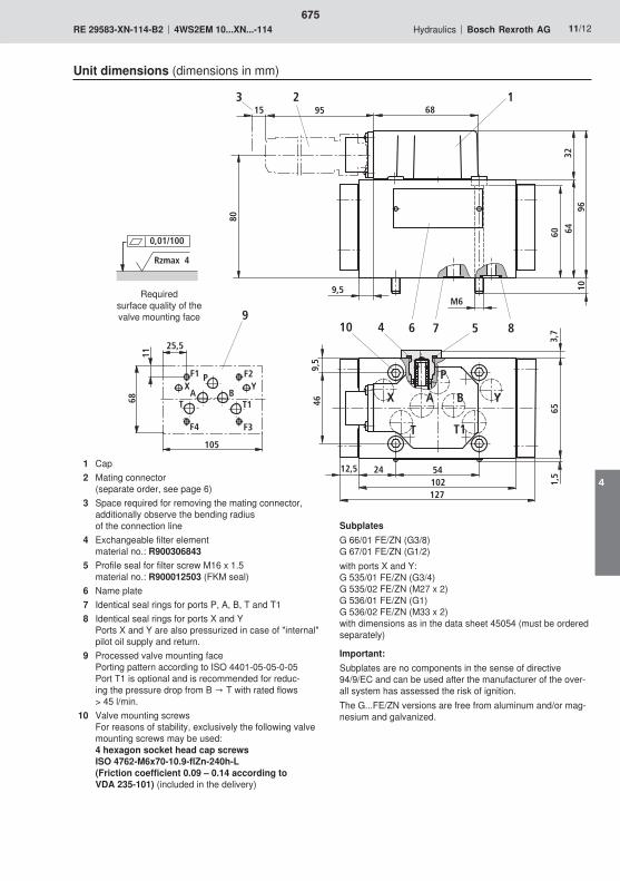
9515 68
9,5M6
80
60 6432
9610
3 1
5424102127
12,5
46
653,
7
9,5
P
A B
T1T
YX
57 810
1,5
6
2
4
F1 F2P
BAT
F3F4
105
25,5
6811
T1
9
X Y
0,01/100
Rzmax 4
675
4
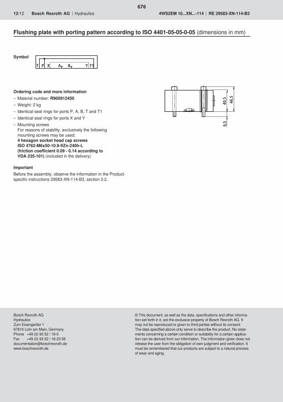
9,5
40,5
46,5
T P X A B Y T1
676

677

678
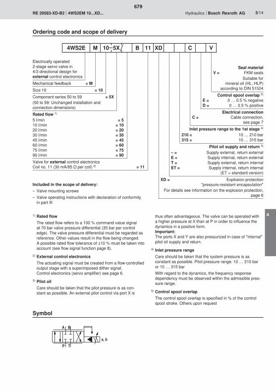
� '
$�
5)�8
679
4
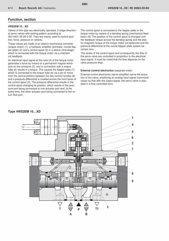
0
�
�
�
1
2
3
$�
�'
$�
680
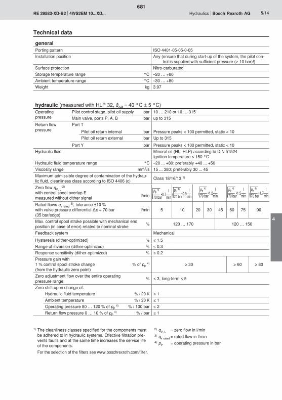
681
4
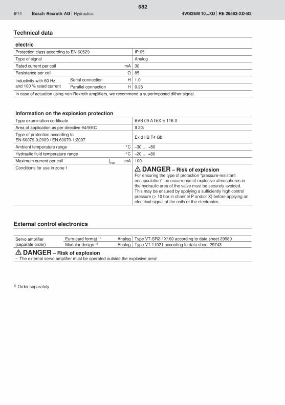
682
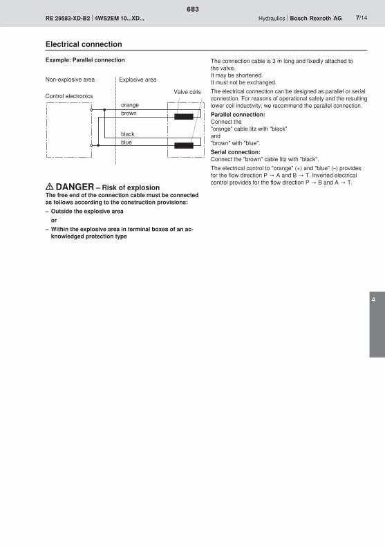
683
4
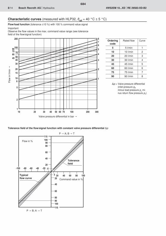
���1�
0�
3�
��
�
��
0�
�
���1�3�
!��!�!0�!3�
��� 0� 3�
!
���
!���
���
���
��
��
��
�
2�
���
�
���
�
�
�
023
������ 2��� ��� �������
�
3
�
0�21�
0�
684
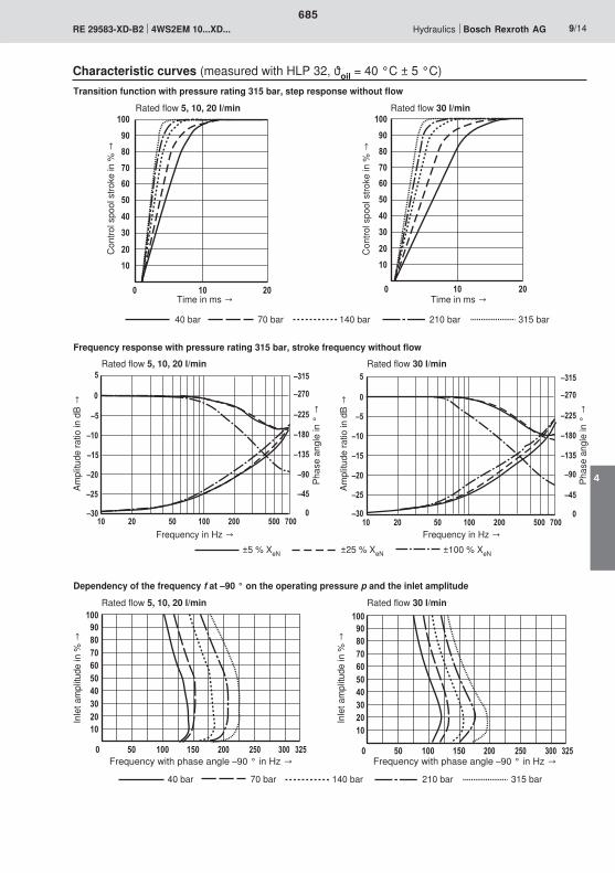
�
��������0�2�3�1�
���
� ��� �� ��� �� ��� ��
<��
<�
<��
<�
<��
<
�
�� ��� 2���
<
<1�
<��
<�3�
<��
<�2�
<��
� ���� ���
� ��
�
0�
3�
���
��
��
��
�
2�
��
1�
� ��
�
0�
3�
���
��
��
��
�
2�
��
1�
<��
<�
<��
<�
<��
<
�
�� ��� 2���
<
<1�
<��
<�3�
<��
<�2�
<��
� ���� ���
�
��������0�2�3�1�
���
� ��� �� ��� �� ��� ��
685
4
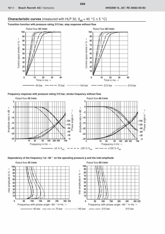
� ��
�
0�
3�
���
��
��
�� �
��
�
2�
��
1�
� ��
�
0�
3�
���
��
��
�� �
��
�
2�
��
1�
� �� � ���
<�
<��
<�
<��
<
�
��� 2��
<��
<���
<1�<0�<��
��<�<��
��� � �� � ���
<�
<��
<�
<��
<
�
��� 2��
<��
<���
<1�<0�<��
��<�<��
���
�
��������0�2�3�1�
���
� ��� �� ��� �� ��� �� �
��������0�2�3�1�
���
� ��� �� ��� �� ��� ��
686
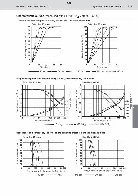
� ��
�
0�
3�
���
��
��
��
��
�
2�
��
1�
� � ��
�
0�
3�
���
��
��
��
��
�
2�
��
1�
�
� �� � ���
<�
<��
<�
<��
<
�
��� 2��
<��
<���
<1�<0�<��
��<�<��
��� � �� � ���
<�
<��
<�
<��
<
�
��� 2��
<��
<���
<1�<0�<��
��<�<��
���
�
��������0�2�3�1�
���
� ��� �� ��� �� ��� �� �
��������0�2�3�1�
���
� ��� �� ��� �� ��� ��
687
4
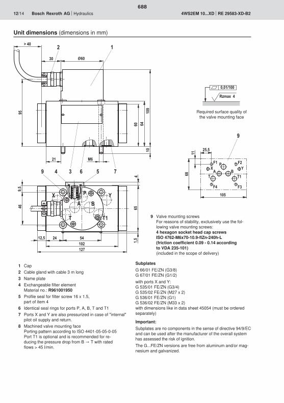
�� 0�
�� �0
1
0� 0��
1��
�
�
������2
��)
0 0
1)
�
� '
$�$
��
21
�)
0
�
B��
�� ���
'�$
���
��
�)
03��
$�
1
� �
Rzmax 4
0,01/100
688
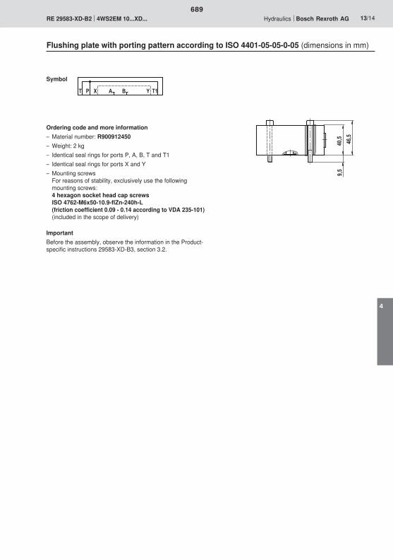
1)
�)
0)
$ � � � ' � $�
689
4

690
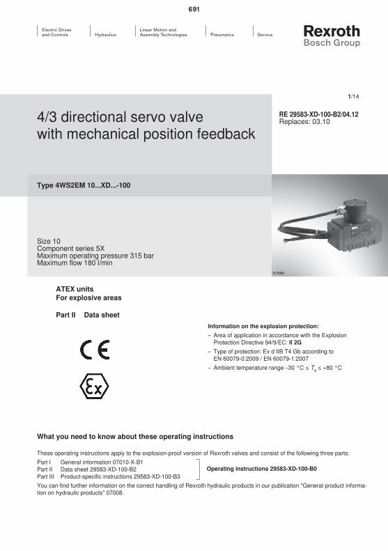
691

692
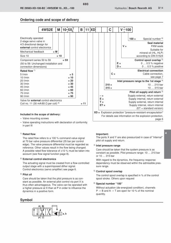
� '
$�
5)�8
693
4
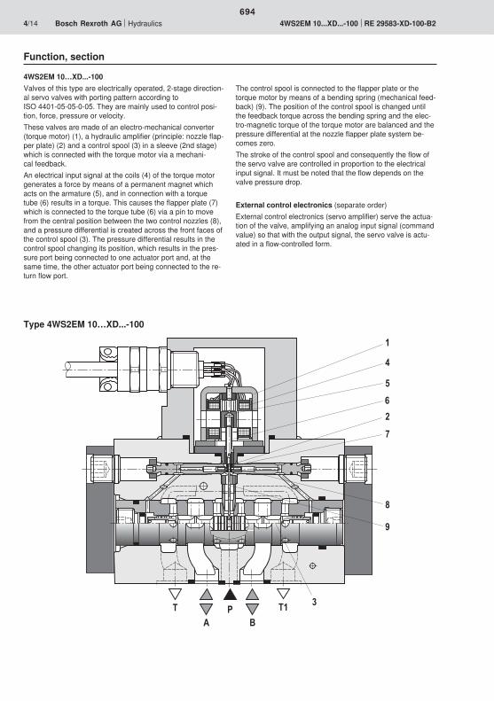
0
�
�
�
1
2
3
$�
�'
$�
694
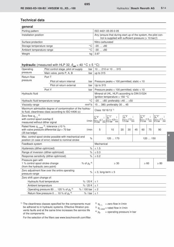
695
4
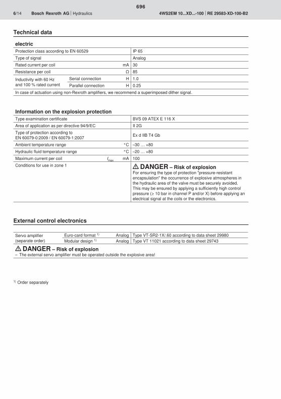
696
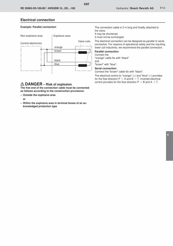
697
4
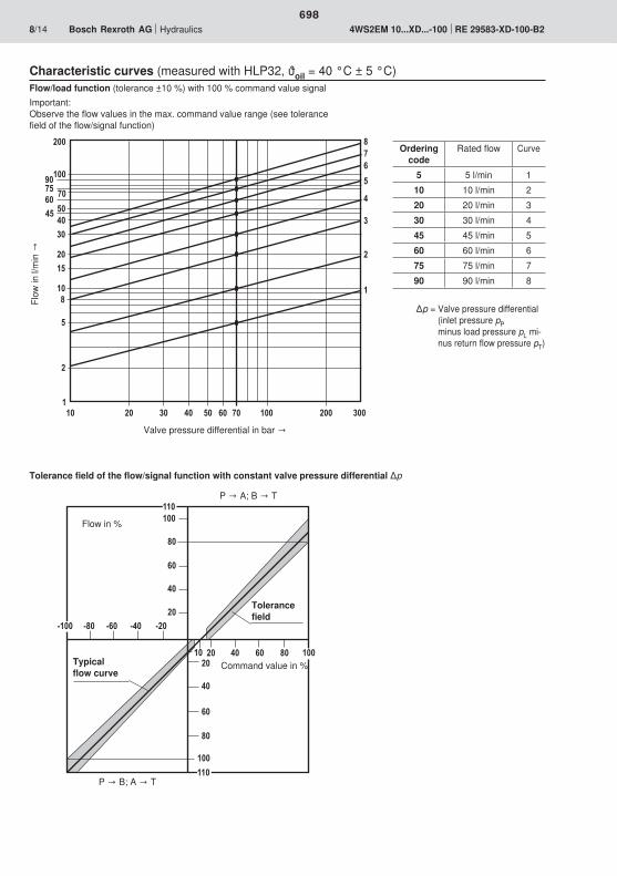
���
0�
3�
��
�
��
0�
�
���
3�
!��!�!0�!3�
��� 0� 3�
���
!���
���
���
��
��
��
��
�
2�
���
�
���
�
�
�
023
������ 2��� ��� �������
�
3
�
0�21�
0�
698

�
��������0�2�3�1�
���
� ��� �� ��� �� ��� ��
<��
<�
<��
<�
<��
<
�
�� ��� 2���
<
<1�
<��
<�3�
<��
<�2�
<��
� ���� ���
� ��
�
0�
3�
���
��
��
��
�
2�
��
1�
� ��
�
0�
3�
���
��
��
��
�
2�
��
1�
<��
<�
<��
<�
<��
<
�
�� ��� 2���
<
<1�
<��
<�3�
<��
<�2�
<��
� ���� ���
�
��������0�2�3�1�
���
� ��� �� ��� �� ��� ��
699
4
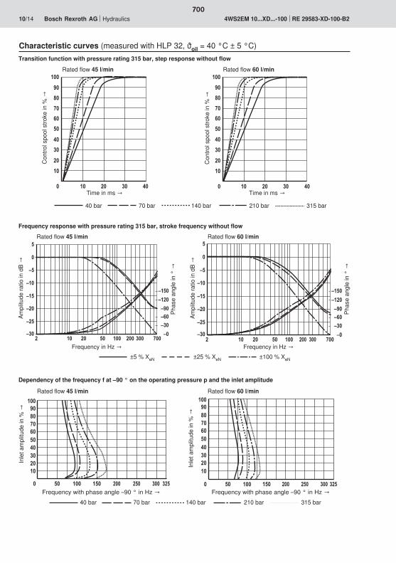
� ��
�
0�
3�
���
��
��
�� �
��
�
2�
��
1�
� ��
�
0�
3�
���
��
��
�� �
��
�
2�
��
1�
� �� � ���
<�
<��
<�
<��
<
�
��� 2��
<��
<���
<1�<0�<��
��<�<��
��� � �� � ���
<�
<��
<�
<��
<
�
��� 2��
<��
<���
<1�<0�<��
��<�<��
���
�
��������0�2�3�1�
���
� ��� �� ��� �� ��� �� �
��������0�2�3�1�
���
� ��� �� ��� �� ��� ��
700

� ��
�
0�
3�
���
��
��
��
��
�
2�
��
1�
� � ��
�
0�
3�
���
��
��
��
��
�
2�
��
1�
�
� �� � ���
<�
<��
<�
<��
<
�
��� 2��
<��
<���
<1�<0�<��
��<�<��
��� � �� � ���
<�
<��
<�
<��
<
�
��� 2��
<��
<���
<1�<0�<��
��<�<��
���
�
��������0�2�3�1�
���
� ��� �� ��� �� ��� �� �
��������0�2�3�1�
���
� ��� �� ��� �� ��� ��
701
4
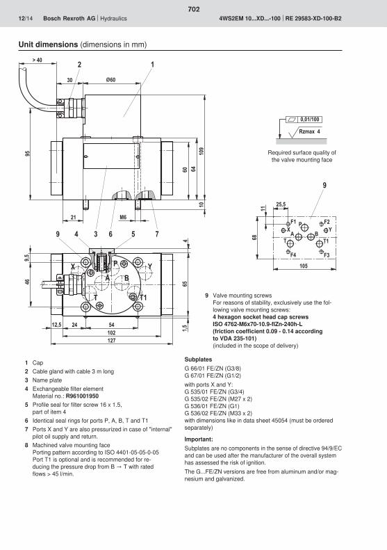
�� 0�
�� �0
1
0� 0��
1��
�
�
������2
��)
0 0
1)
�
� '
$�$
��
21
�)
0
�
B��
�� ���
'�$
���
��
�)
03��
$�
1
� �
Rzmax 4
0,01/100
702

1)
�)
0)
$ � � � ' � $�
703
4

704

Designation TypeComponent
series Data sheet Page
RE 00112-10, Edition: 2013-12, Bosch Rexroth AG
Electronics
Contents | Electronics | Explosion protection
Valve amplifi ers Amplifi er module for controlling the explosion-proof proportional pressure valve, DBET-6X...XE
VT-MSPA1-200 1X 30223-200 707
Amplifi er module for controlling the explosion-proof proportional directional valves 4WRA...XE, 3DREP 6...XE and 4WRZ...XE
VT-MSPA2-200 1X 30228-200 713
Monitoring moduleModule for monitoring and limiting the solenoid currents in proportional valves
VT-MUXA2-2 1X 30290 721
1
2
3
4
5
6
705
5

Bosch Rexroth AG, RE 00112-10, Edition: 2013-12
706

707

708
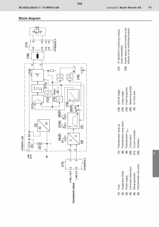
(F)
t <
t >
I >(6
)(7
)(8
)
(10)
Gw
36
(4)
(5)
(15)
(3)
(11)
(13)
(12)
(14)
(1)
(2)
2
54
U
U
DC
DC
1
Wi
(16)
PT
+U
B24
V
0V
(–IN
) 0 V
(+IN
) +10
V
Zw(F
)
Pow
er
(9)
5 621
VT-M
UXA
2-2
151413 1611 129 10
(F)
(F)
(17)
(17)
(18)
VT-M
SPA
1-20
0
VT-M
UXA
2-2
709
5
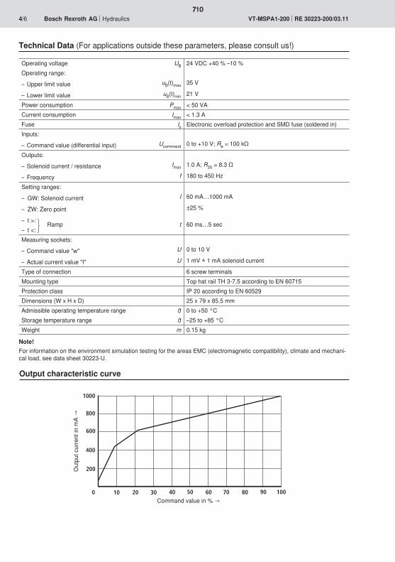
1000
800
600
400
200
0 10 20 30 40 6050 70 80 90 100
710

RexrothVT-MSPA1-200
GwZw
t <
t >
4 5 6
1 2 3
w I
85,5
79
25
711
5
712
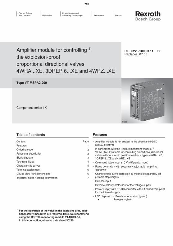
713

714
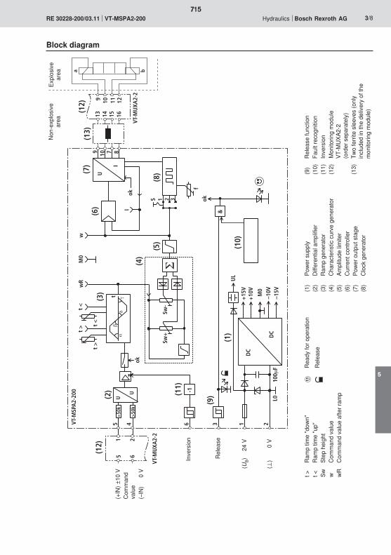
45t
6 3
UL
DC
DC
L0
+15
V+
10V
M0
–10V
–15V
21
Sw+
Sw-
U
I
wR
t >
-1
M0
U
U>
50k
(1)
(9)
(3)
(4)
(5)
(6)
(7)
&
ok
okok
(10)
100
F
f
(8)
t <
wt
<
(2)
7 89 10
(11)
t >
S 1 2 3
>50
k
I
VT-M
SPA
2-20
0
(12)
(12)
a b
151413 1611 129 10
5 621
(13)
VT-M
UXA
2-2
VT-M
UXA
2-2
715
5

716
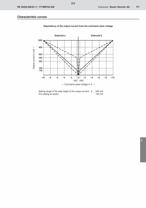
1000
800
600
500
400
200
–10 –8 –6 –4 –2 0 +10+8+6+4+2–0,2 +0,2
150
717
5
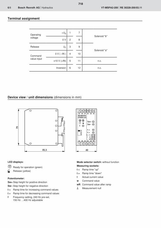
85,5
79
40
321
7
Sw+Sw–
t <t >
8 9
4 5 6
10 11 12
t < t >I w
wR
REXROTHVT-MSPA2-200
f
123
718
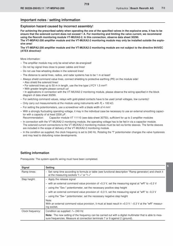
719
5

720

721
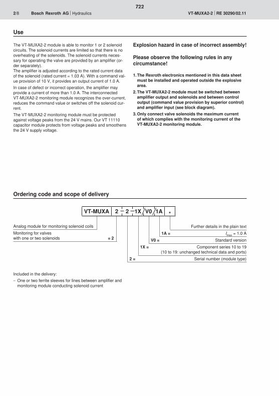
722

723
5

NTF
24V
NTFDI
K1
NTF
DI
K2
K2
1,25
A
1,25
A
K1K1
IVS
IRS
AV
AV
AR
BV
BV BRBRA
R
REF
REF
DC D
C
375
mA
IVS
IRS
K2
R RRR
3 3
55
1
6
77
8
92
I I
4
IRS
DI
IVS
Rese
t
13 14 15 16 3 4 5 621871211109
4 5
6 3
10
4 51413
12
VT-M
SPA
1-20
0VT
-MU
XA2-
2
1 2
4 5+ –
1 2/3
4
5/6
724
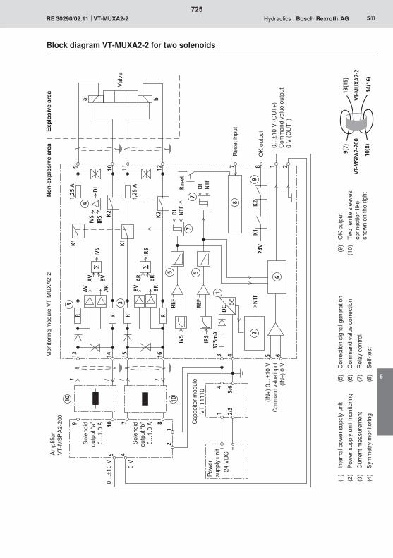
NTF
24V
NTFDI
K1
NTF
DI
K2
K2
1,25
A
1,25
A
K1K1
IVS
IRS
AV
AV
AR
BV
BV BRBRA
R
REF
REF
DC D
C
375m
A
IVS
IRS
K2
R RRR
3 3
55
1
6
77
8
92
I I I I
4
IRS
DI
IVS
Rese
t
13 14 15 16 3 4 5 621871211109
a b
7 89 105 4
1010
9(7)
10(8
)14
(16)
13(1
5)
12
VT-M
SPA
2-20
0VT
-MU
XA2-
2
+ –
1 2/3
4
5/6
725
5
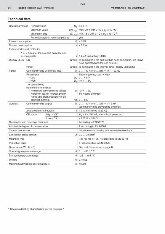
726
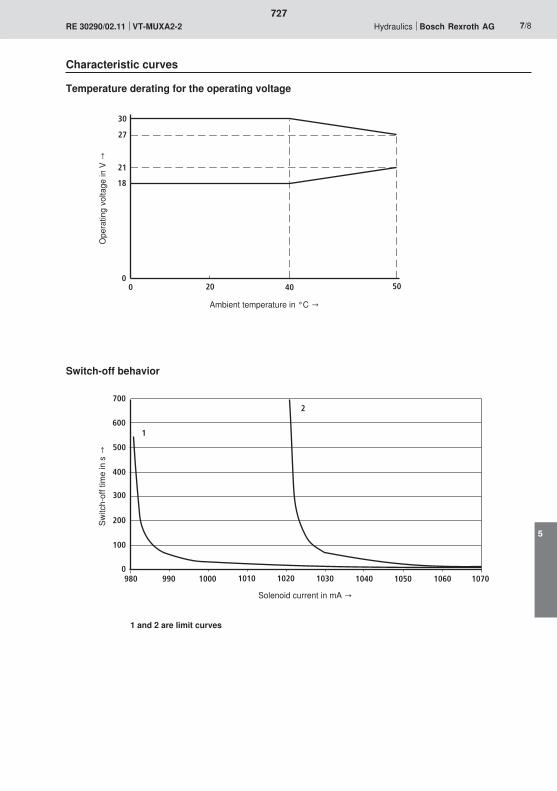
30
27
21
18
0 20 40 500
700
600
500
400
300
200
100
0980 990 1000 1010 1020 1030 1040 1050 1060 1070
1
2
727
5
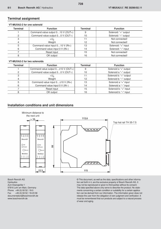
22,5 115
113,6
99
M UXA2
Powe r
O K
Rese t
13 14 15 169 10 11 12
5 6 7 81 2 3 4
M UXA2
Powe r
O K
Rese t
13 14 15 169 10 11 12
5 6 7 81 2 3 4
> 10
728
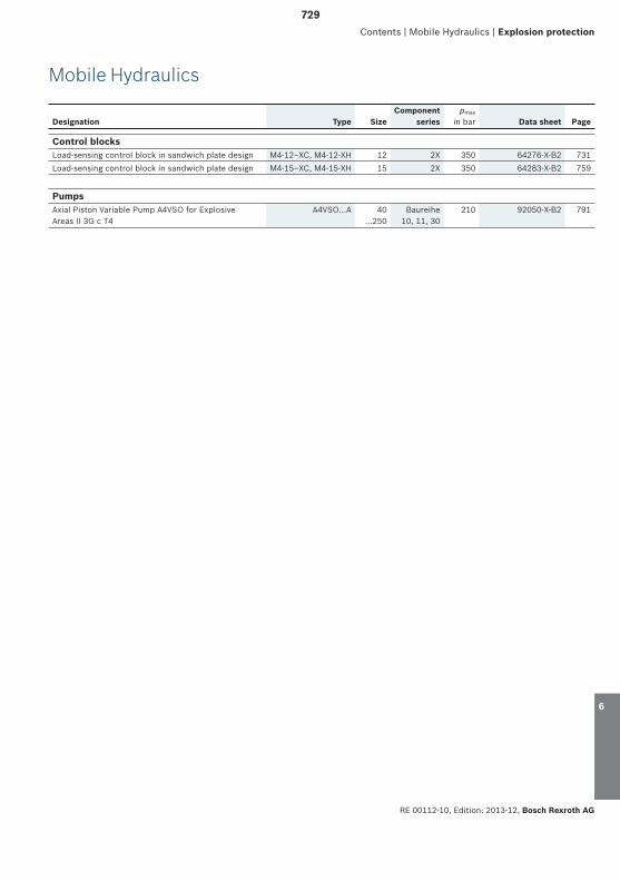
RE 00112-10, Edition: 2013-12, Bosch Rexroth AG
Designation Type SizeComponent
seriespmax
in bar Data sheet Page
Mobile Hydraulics
Contents | Mobile Hydraulics | Explosion protection
Control blocksLoad-sensing control block in sandwich plate design M4-12–XC, M4-12-XH 12 2X 350 64276-X-B2 731Load-sensing control block in sandwich plate design M4-15–XC, M4-15-XH 15 2X 350 64283-X-B2 759
PumpsAxial Piston Variable Pump A4VSO for Explosive Areas II 3G c T4
A4VSO...A 40 ...250
Baureihe10, 11, 30
210 92050-X-B2 791
1
2
3
4
5
6
729
6

Bosch Rexroth AG, RE 00112-10, Edition: 2013-12
730

731

732

733
6

�
� � �
��� �����
�
�
�
�
�
�� ��
�
�
���
��
�
�
���
���
��
� �
� �
�
���
� ����� ����
�
��
�
�
�
��
��
734
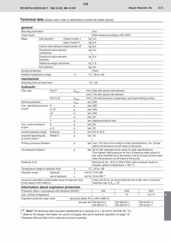
735
6

1
2
3n.c.
736

A B
/ /
A
n.c.n.c.
C
B
D
PA PA
2)
737
6

2.4
2.
2.2
3.
2.1
2.3
1.
A
B
A
B
CA
B
A
B
D
C
A
738
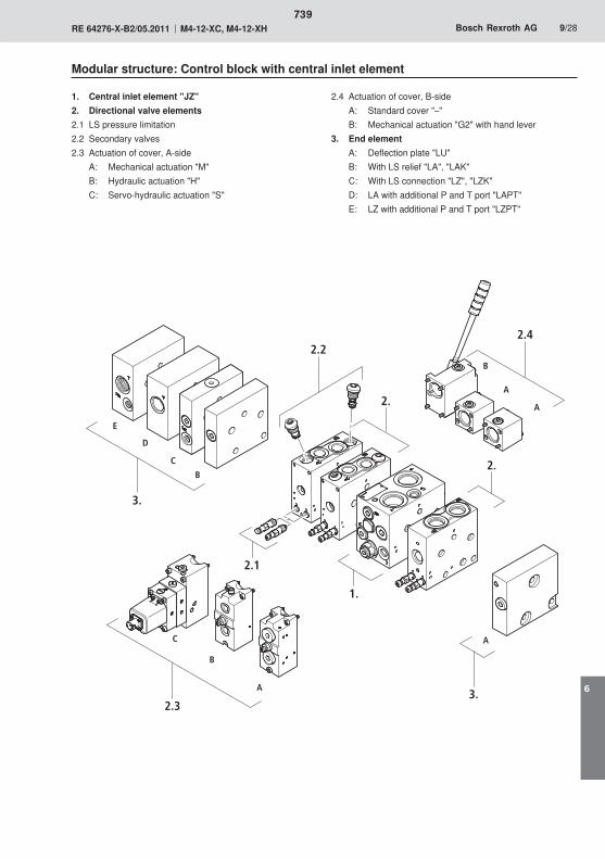
2.
2.4
2.
2.2
3.
2.1
2.33.
1.
A
B
A
B
C
D
E
C
A
A
B
739
6
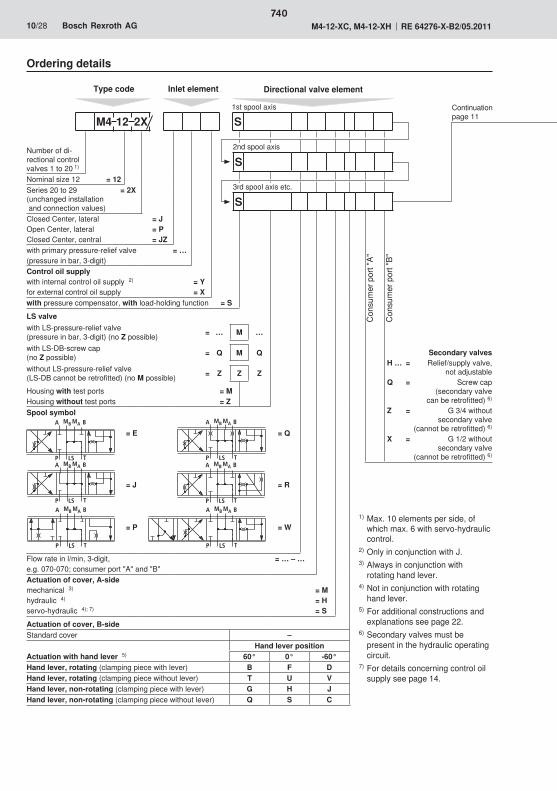
740
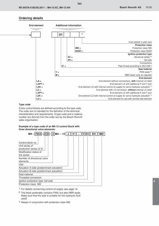
741
6
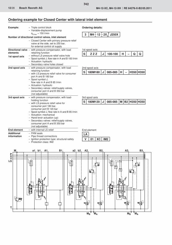
�
�
�
�
�� ������ � ��� � �
�
�
�
�
�
�
�
�
�
�
� �
��
��������
742
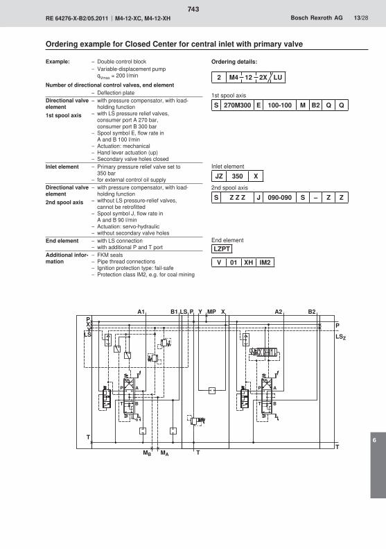
�
�
�
�
�� ��
� �
��
�
� � � ���
�
�
�
�
�
� �
����
��
�
�
743
6
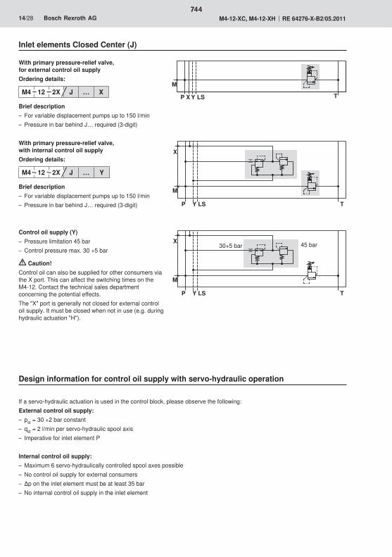
� �� �
�
�
�
�
�� ��
� �� �
�
�
744
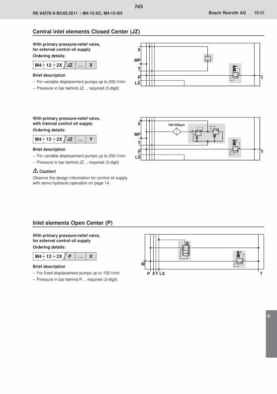
� ��
�
� ��������
��
� ��
�
�
��
� �� ��
�
745
6
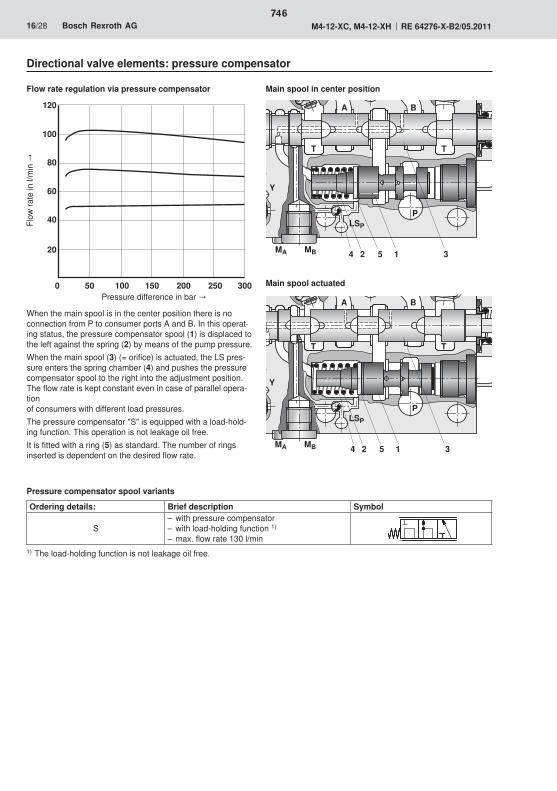
�
�
��
��
��
��
���
�� ��� ��� �� �� ��
�� � � � ��
��
�
��
� �
�
�� � � � ��
��
�
��
� �
�
746
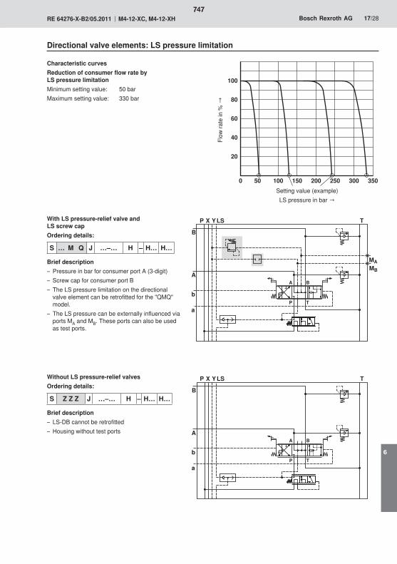
� �� ��� ��� �� �� �� ��
�
��
��
��
���
�
����
� �
�
��
�
� �
� �
�
�
�� �
�
��
�
� �
� �
�
�
747
6
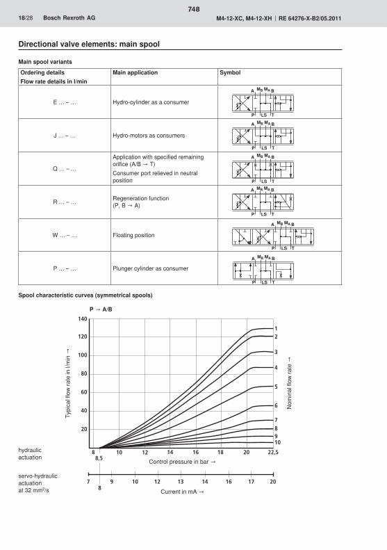
� � �
�� ����
� � �
�� ����
� � �
�� ����
� � �
�� ����
� � �
�� ����
� � �
�� ����
� ��
���� �� �� �� � �
� � �� �� �� �� �
��
�
�
�
�
�
�
�
�
��
��
��
�
748
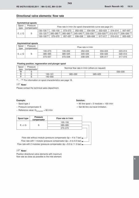
749
6
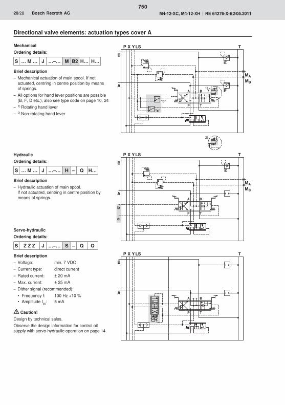
��
��
�
����
� �
�
��
�
� �
� �
���
���
�
����
� �
�
��
�
� �
� �
�
�
�� �
�
��
�
� �
� �
750
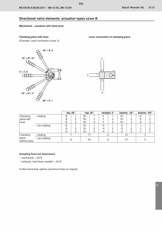
0˚ = F, H
30˚ = B1, G1
-30˚ = D1, J1
1
2
3
60˚ = B, G
-60˚ = D, J
751
6
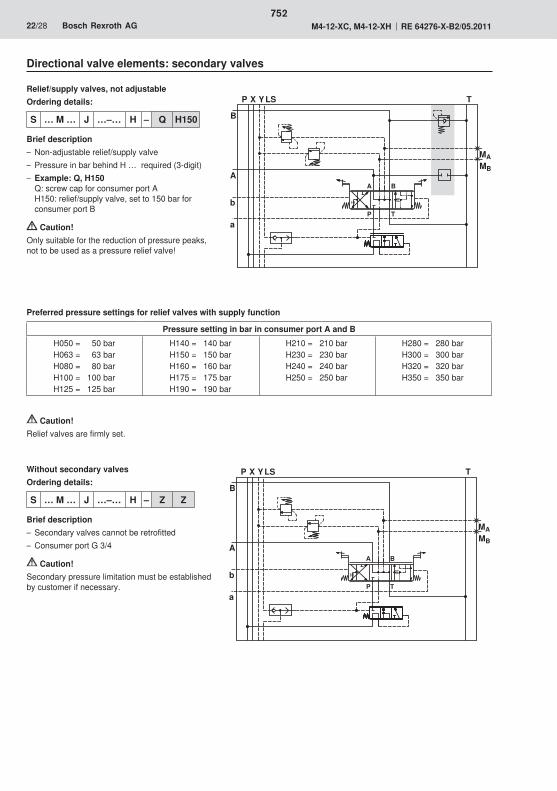
�
����
� �
�
��
�
� �
� �
�
�
�
����
� �
�
��
�
� �
� �
�
�
752
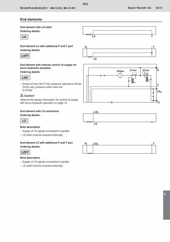
� �
�
��
�
��
�� ��
��
��
�
�� �� ������ ������
753
6
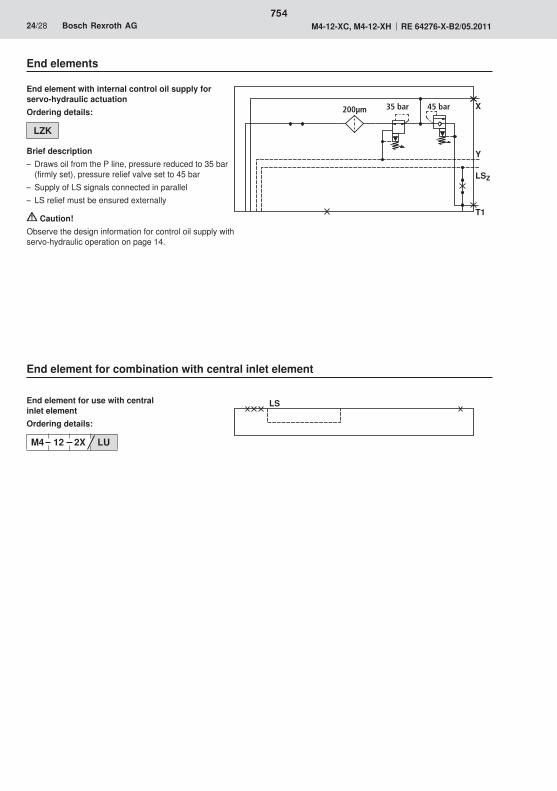
�
��
��
�
�� �� ������ ������
754
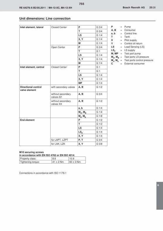
755
6

3025
25
31
46,5
28
3022
39
30
38,5
40 27
13
65
89125
56
86
157
4520
9
63
25
49
83,5
18
48
85
114
4646
4650
86,5
114
74
114,5
67
15
83,5
60˚
15
1
2
3.1 4.1
5
6
7
9
8
10
3.24.2
13
103
19
103
756

3546,5
34,5
31
25
25
3025
37
8,5
27
27
39
25
301513
2535
7699
137
536523
4698125
50
6393114
466080
46
43
114
74
23
103
15
13
19
103
20
209
5686
15767
125169
15
63
87
60˚
12
3.1
3.2
4.1
4.2
5
6
7
8
9
10
11
86,5
56,5
112,5
83,5
114,5
757
6

758

759

760
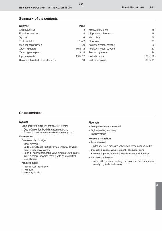
761
6
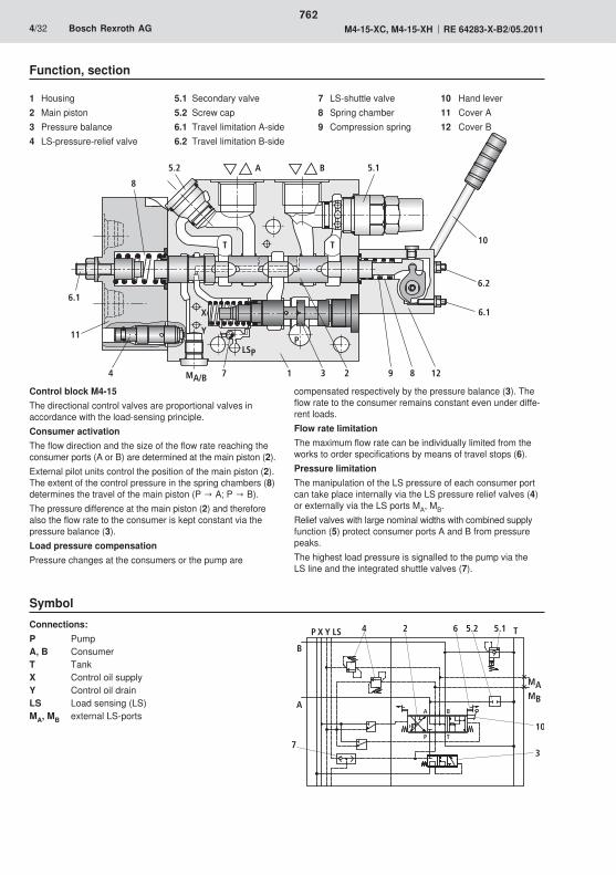
�
762
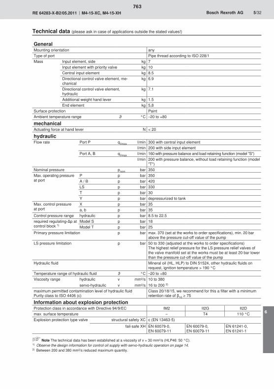
763
6
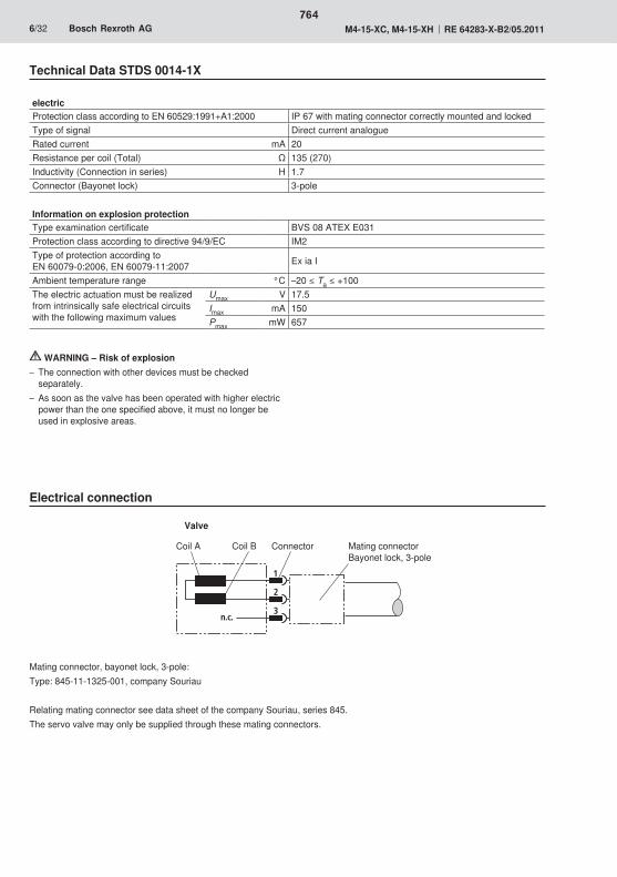
1
2
3n.c.
764
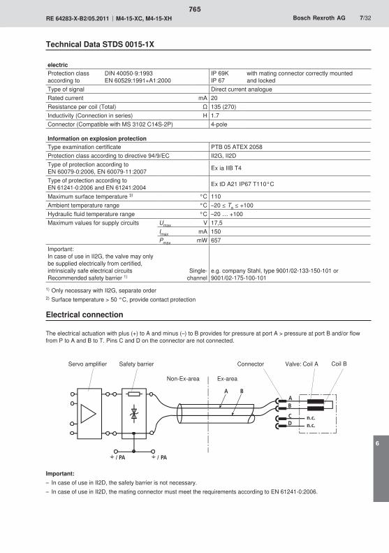
A B
/ /
A
n.c.n.c.
C
B
D
PA PA
2)
765
6
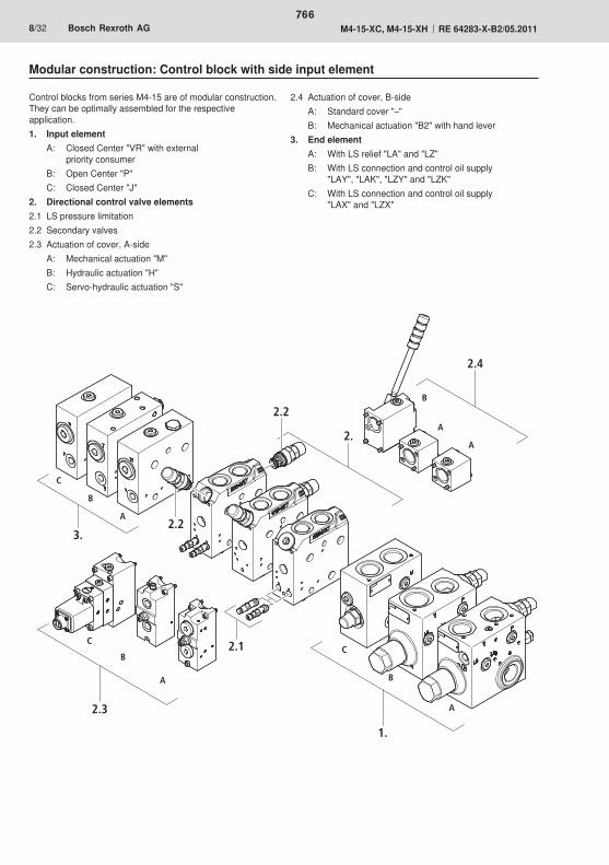
2.4
2.
3.
2.3
1.
A
B
A
B
A
B
C
2.2
A
B
C
C
A
2.2
2.1
766

2.
1.
2.4
2.
3.
2.1
2.3 3.
A
B
A
B
D
E
C
A
B
2.2
A
B
C
A
2.2
767
6
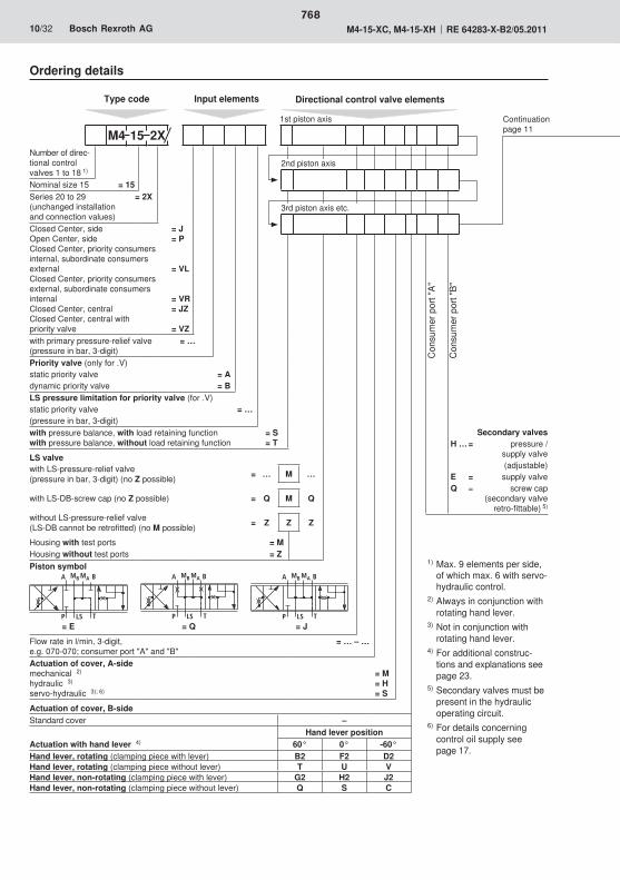
768
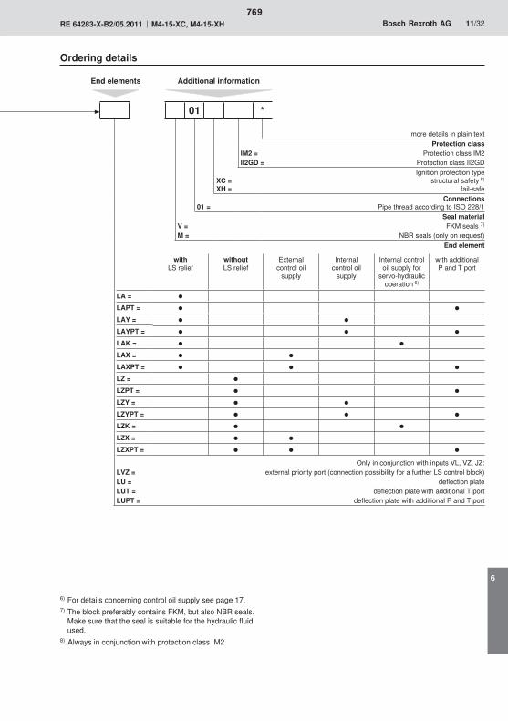
769
6
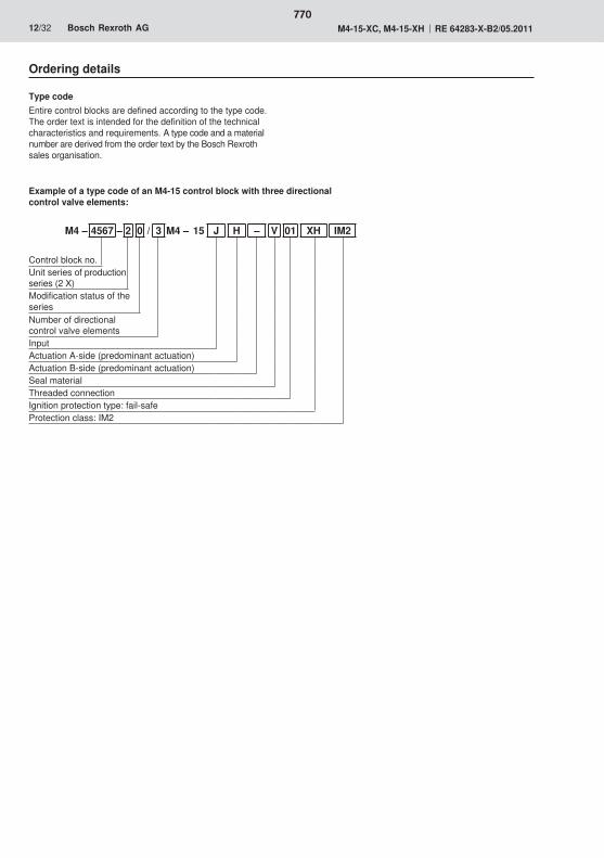
770
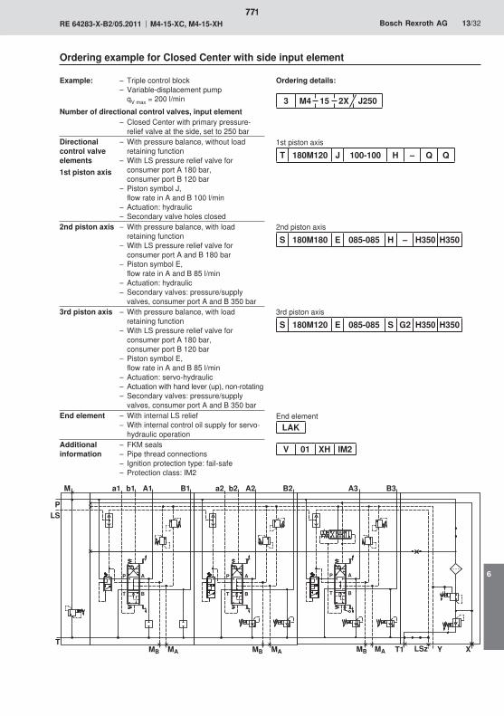
�
�� ��
��� ������
�� ��
� ���
�
�
��
�� ��
�
�
�
�
�
�
�
�
�
�
�
�
�� �� � �
771
6
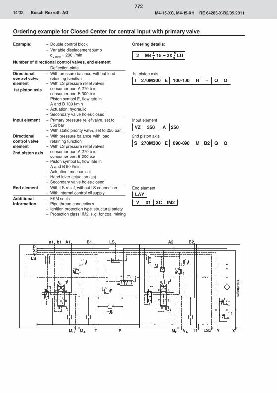
�
��
��
��
� �
�
�� ��
� �
�� �� � �
��������
�
�
�
�
�
�
�
�
�
�� ��
�� ��
772
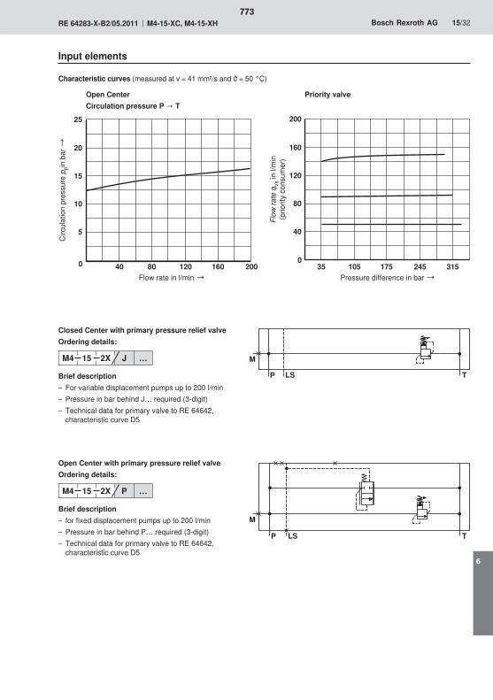
� �� ��
�
��
��
�
�
�� �� ����
� ��� ��� �� ��
��
��
��
���
��
� � �
�
� � �
�
773
6
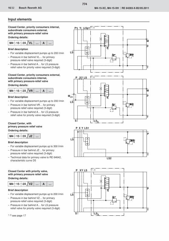
�
�
�
� � � ��
�
�
�
�
��� �
� ��
�
�
�
�
������
�
�
�
�
���
� �
�
� ��
774
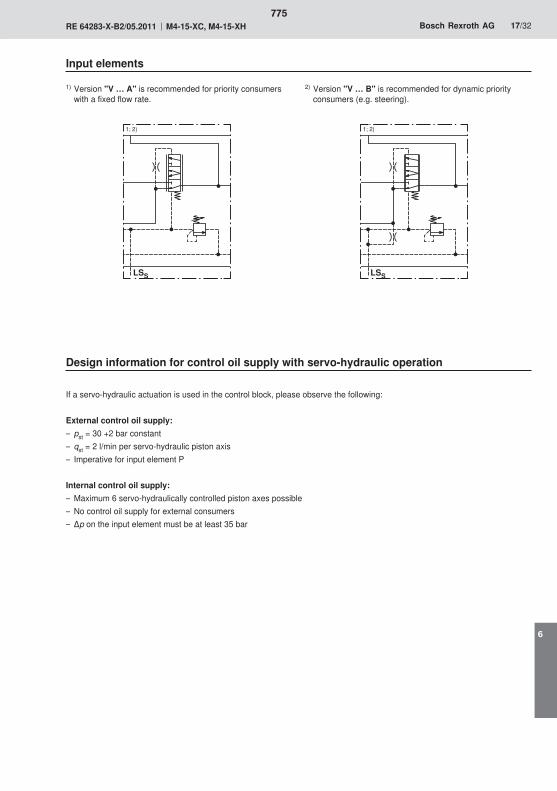
�� ��
775
6

� �� ��� ��� �� �� ��
�
��
��
��
���
��
���
���
�
�
�
� �
���
� �
�����
�
�
�
� �
���
� �
�����
776
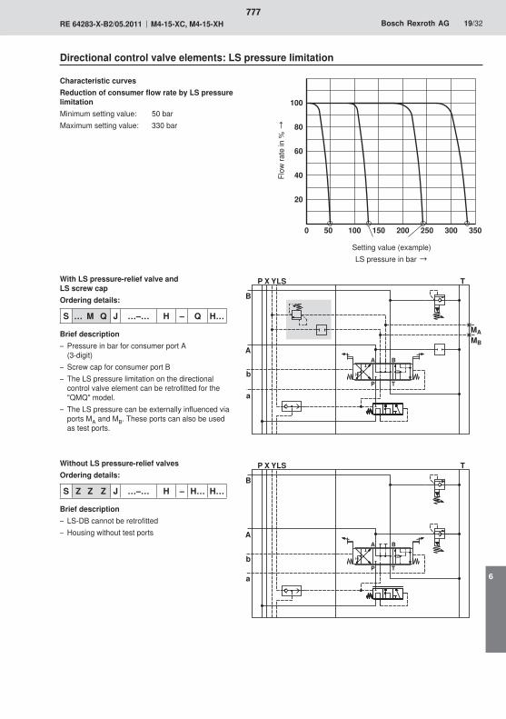
� �� ��� ��� �� �� �� ��
�
��
��
��
���
� � �
�
��
�
��
� �
� �
��
�
�
� � �
�
��
�
� �
� �
�
�
777
6
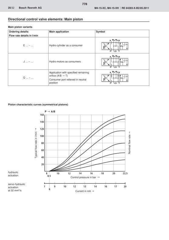
� � �
�� ����
� � �
�� ����
� � �
�� ����
� ��
���� �� �� �� � �
� � �� �� �� �� �
�
�
�
�
��
��
�
��
778
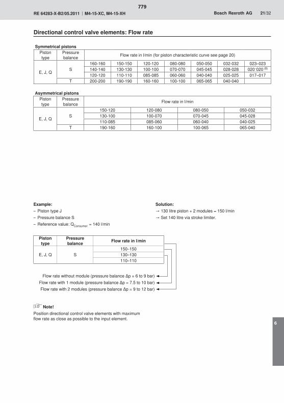
779
6
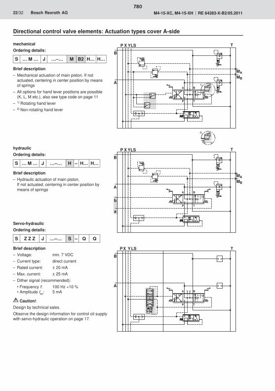
� �
� �
�� �
�
��
�
��
��
����
� �
� �
�� �
�
��
�
�
�
����
� � �
�
��
�
� �
� �
780
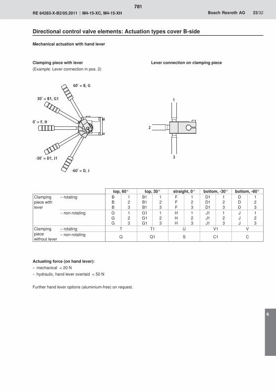
0˚ = F, H
30˚ = B1, G1
-30˚ = D1, J1
1
2
3
60˚ = B, G
-60˚ = D, J
781
6
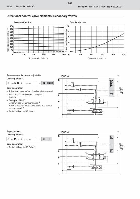
� � �
�
��
�
��
� �
� �
��
�
�
� � �
�
��
�
��
� �
� �
��
�
�
� �� �� �� ��� ��
��������������������
��
�� ���� ��� ���
�
�
�
��
782

��
��
�
��
��
���
��
��
�
��� �� ��
��
�������� ������
��
��
�
��� �� ��
��
��
��
������ ������
783
6

��
��
�
��
��
���
��
��
� �
�� �� ��
��
��
� �
�� �� ��
��
��
��
�
�� �� ������ ������
��
��
784
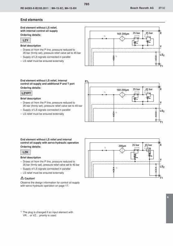
��
��
�
��� �� ��
��
��
������ ������
��
��
�
�� �� ������ ������
��
��
��
��
�
��� �� ��
��
��
��
������ ������
785
6
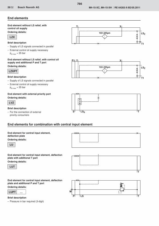
�
�� �
�
� ���
��
��
� �
�� �� ��
��
��
� �
�� �� ��
��
786
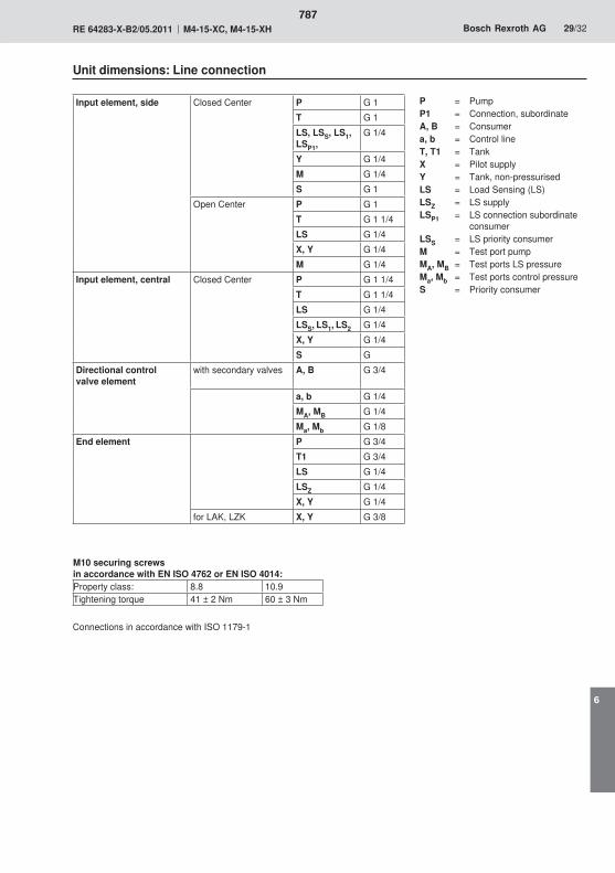
787
6

22
30
18282520
27
22
133
3532
38
88
93
133
T
PA1 B1
A2 B2
A3 B3
65
3 x
51 =
153
130
58
92
130
32
54
LSZ
Y T
M
LS
1
6
94.2
5
3
2
7
4.3
8
92,5
4548,590
65
93,5
12,5
25,5
284
50
25,5
82,5
4069 69
5151
51
131
207
169
451
149
4.4
4.1
X
31
115
788
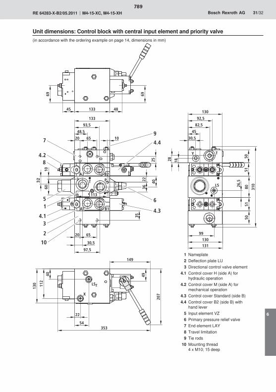
30,5
30,5
22
22
20
182825
20
133
130
Y T
92,5
4548,5
65
93,5
50
82,5
65
97,5
35
A1 B1
A2 B2
T P
36
1060
5180
5150
9926
,5130131
310
LSZ
X
133
69 69
207
149
353
40
112
130
49
113
10
45 48
54
1
40
5
34.1
4.2
6
79
2
4.3
8
LS
4.4
10
789
6

790
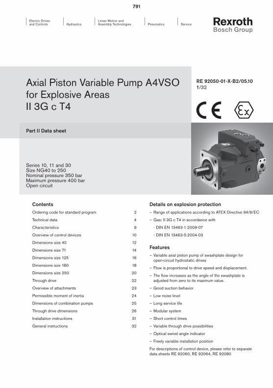
Linear Motion andAssembly Technologies ServicePneumaticsHydraulics
Electric Drives and Controls
Part II Data sheet
Axial Piston Variable Pump A4VSO for Explosive Areas II 3G c T4
RE 92050-01-X-B2/05.10 1/32
Series 10, 11 and 30Size NG40 to 250Nominal pressure 350 barMaximum pressure 400 barOpen circuit
Details on explosion protection – Range of applications according to ATEX Directive 94/9/EC
– Gas: II 3G c T4 in accordance with
- DIN EN 13463-1:2009-07
- DIN EN 13463-5:2004-03
Features – Variable axial piston pump of swashplate design for open-circuit hydrostatic drives
– Flow is proportional to drive speed and displacement.
– The flow increases as the angle of the swashplate is adjusted from zero to its maximum value.
– Good suction behavior
– Low noise level
– Long service life
– Modular system
– Short control times
– Variable through drive possibilities
– Optical swivel angle indicator
– Freely variable installation position
For descriptions of control device, please refer to separate data sheets RE 92060, RE 92064, RE 92080
ContentsOrdering code for standard program 2
Technical data 4
Characteristics 9
Overview of control devices 10
Dimensions size 40 12
Dimensions size 71 14
Dimensions size 125 16
Dimensions size 180 18
Dimensions size 250 20
Through drive 22
Overview of attachments 23
Permissible moment of inertia 24
Dimensions of combination pumps 25
Through drive dimensions 26
Installation instructions 31
General instructions 32
791
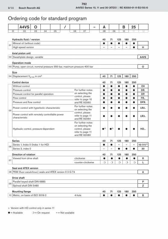
2/32 Bosch Rexroth AG A4VSO Series 10, 11 and 30 (ATEX) RE 92050-01-X-B2/05.10
Hydraulic fluid / version 40 71 125 180 250
01Mineral oil (without code) ● ● ● ● ●
High-speed version – – – – ● H
Axial piston unit02 Swashplate design, variable A4VS
Operation mode03 Pump, open circuit, nominal pressure 350 bar, maximum pressure 400 bar O
Size04 Displacement Vg max in cm3 40 71 125 180 250
Control device 40 71 125 180 250
05
Without control ● ● ● ● ● OV
Pressure control For further notes on selecting the control, please refer to page 10 and RE 92060
● ● ● ● ● DR.
Pressure control for parallel operation ● ● ● ● ● DP.
Flow control ● ● ● ● ● FR..
Pressure and flow control ● ● ● ● ● DFR.
Power control with hyperbolic characteristicFor further notes on selecting the control, please refer to page 11 and RE 92064
● ● ● ● ● LR2..
Power control with remotely controllable power characteristic ● ● ● ● ● LR3..
Hydraulic control, pressure-dependent
For further notes on selecting the control, please refer to page 11 and RE 92080
●1) ●1) ● ● ● HD...
Series 40 71 125 180 250
06Series 1, Index 0 (Index 1 for HD) ● ● – – – 10 (11)1)
Series 3, index 0 – – ● ● ● 30
Direction of rotation 40 71 125 180 250
07Viewed from drive shaft clockwise ● ● ● ● ● R
counter-clockwise ❍ ❍ ❍ ❍ ❍ L
Seal and ATEX version08 FKM (fluor-caoutchouc) seals and ATEX version II 3 G T4 A
Drive shaft
09Parallel keyed shaft DIN 6885 P
Splined shaft DIN 5480 Z
Mounting flange 40 71 125 180 25010 Metric, on basis of ISO 3019-2 4-hole ● ● ● ● ● B
A4VS O / – A B 2501 02 03 04 05 06 07 08 09 10 11 12
Ordering code for standard program
1) Version with HD control only in series 11
● = Available ❍ = On request – = Not available
792
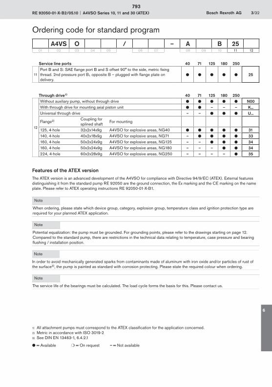
RE 92050-01-X-B2/05.10 A4VSO Series 10, 11 and 30 (ATEX) Bosch Rexroth AG 3/32
Service line ports 40 71 125 180 250
11Port B and S: SAE flange port B and S offset 90° to the side, metric fixing thread. 2nd pressure port B1 opposite B – plugged with flange plate on delivery.
● ● ● ● ● 25
Through drive1) 40 71 125 180 250
12
Without auxiliary pump, without through drive ● ● ● ● ● N00With through drive for mounting axial piston unit ● ● – – – K...Universal through drive – – ● ● ● U...
Flange2) Coupling for splined shaft
For mounting
125, 4-hole 32x2x14x9g A4VSO for explosive areas, NG40 ● ● ● ● ● 31140, 4-hole 40x2x18x9g A4VSO for explosive areas, NG71 – ● ● ● ● 33160, 4-hole 50x2x24x9g A4VSO for explosive areas, NG125 – – ● ● ● 34160, 4-hole 50x2x24x9g A4VSO for explosive areas, NG180 – – – ● ● 34224, 4-hole 60x2x28x9g A4VSO for explosive areas, NG250 – – – – ● 35
Features of the ATEX versionThe ATEX version is an advanced development of the A4VSO for compliance with Directive 94/9/EC (ATEX). External features distinguishing it from the standard pump RE 92050 are the ground connection, the Ex marking and the CE marking on the name plate. Please refer to ATEX operating instructions RE 92050-01-X-B1.
Note
When ordering, please state which device group, category, explosion group, temperature class and ignition protection type are required for your planned ATEX application.
Note
Potential equalization: the pump must be grounded. For grounding points, please refer to the drawings starting on page 12. Compared to the standard pump, there are restrictions in the technical data relating to temperature, case pressure and bearing flushing / installation position.
Note
In order to avoid mechanically generated sparks from contaminants made of aluminum with iron oxide and/or particles of rust of the surface3), the pump is painted as standard with corrosion protecting. Please state the required colour when ordering.
Note
The service life of the bearings must be calculated. The load cycle forms the basis for this. Please contact us.
Ordering code for standard program
1) All attachment pumps must correspond to the ATEX classification for the application concerned.2) Metric in accordance with ISO 3019-23) See DIN EN 13463-1, 6.4.2.1
● = Available ❍ = On request – = Not available
A4VS O / – A B 2501 02 03 04 05 06 07 08 09 10 11 12
793
6
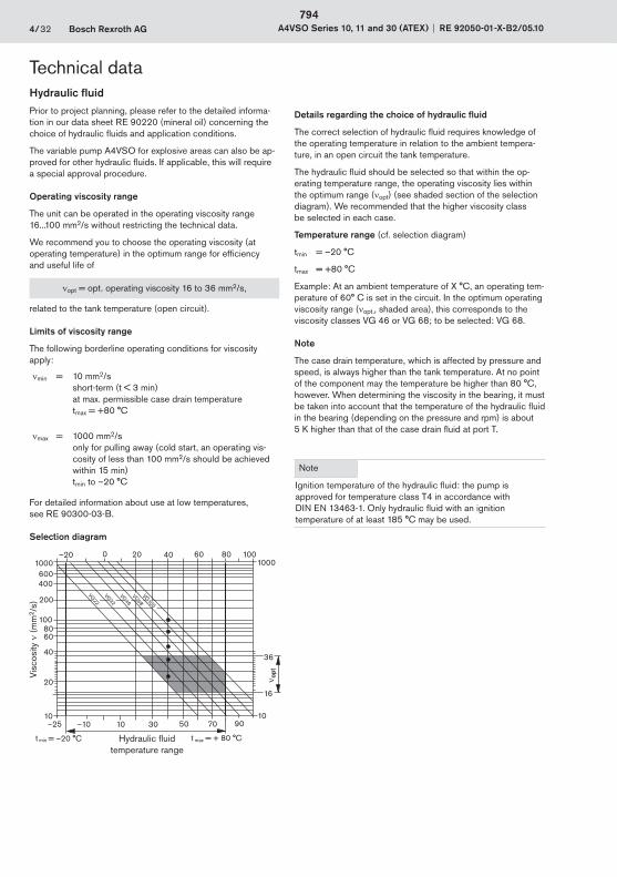
4/32 Bosch Rexroth AG A4VSO Series 10, 11 and 30 (ATEX) RE 92050-01-X-B2/05.10
Hydraulic fluidPrior to project planning, please refer to the detailed informa-tion in our data sheet RE 90220 (mineral oil) concerning the choice of hydraulic fluids and application conditions.
The variable pump A4VSO for explosive areas can also be ap-proved for other hydraulic fluids. If applicable, this will require a special approval procedure.
Operating viscosity range
The unit can be operated in the operating viscosity range 16...100 mm2/s without restricting the technical data.
We recommend you to choose the operating viscosity (at operating temperature) in the optimum range for efficiency and useful life of
opt = opt. operating viscosity 16 to 36 mm2/s,
related to the tank temperature (open circuit).
Limits of viscosity range
The following borderline operating conditions for viscosity apply:
min = 10 mm2/sshort-term (t < 3 min) at max. permissible case drain temperaturetmax = +80 °C
max = 1000 mm2/sonly for pulling away (cold start, an operating vis-cosity of less than 100 mm2/s should be achieved within 15 min)tmin to –20 °C
For detailed information about use at low temperatures, see RE 90300-03-B.
Selection diagram
–25 –10 10
20
30 50 70 90
–20 0 40 60 80 1001000
36
16
10
1000600400
200
1008060
40
20
10
VG 22
VG 32
VG 46VG 68VG 100
t min = –20 °C t max = + 80 °C
Details regarding the choice of hydraulic fluid
The correct selection of hydraulic fluid requires knowledge of the operating temperature in relation to the ambient tempera-ture, in an open circuit the tank temperature.
The hydraulic fluid should be selected so that within the op-erating temperature range, the operating viscosity lies within the optimum range ( opt) (see shaded section of the selection diagram). We recommended that the higher viscosity class be selected in each case.
Temperature range (cf. selection diagram)
tmin = –20 °C
tmax = +80 °C
Example: At an ambient temperature of X °C, an operating tem-perature of 60° C is set in the circuit. In the optimum operating viscosity range ( opt., shaded area), this corresponds to the viscosity classes VG 46 or VG 68; to be selected: VG 68.
Note
The case drain temperature, which is affected by pressure and speed, is always higher than the tank temperature. At no point of the component may the temperature be higher than 80 °C, however. When determining the viscosity in the bearing, it must be taken into account that the temperature of the hydraulic fluid in the bearing (depending on the pressure and rpm) is about 5 K higher than that of the case drain fluid at port T.
Note
Ignition temperature of the hydraulic fluid: the pump is approved for temperature class T4 in accordance with DIN EN 13463-1. Only hydraulic fluid with an ignition temperature of at least 185 °C may be used.
Technical data
Hydraulic fluid temperature range
opt
Visc
osity
(
mm
2 /s)
794

RE 92050-01-X-B2/05.10 A4VSO Series 10, 11 and 30 (ATEX) Bosch Rexroth AG 5/32
Technical dataBearing flushingIn the following operating conditions, bearing flushing is neces-sary for reliable continuous operation:
– Operation with borderline conditions for temperature and viscosity
For vertical installation (drive shaft up) and for above-tank installation (regardless of the shaft position), bearing flushing is specified for lubricating the front bearing and the shaft seal.
Bearing flushing is realized at port U in the area of the front flange of the variable pump. The flushing fluid flows through the front bearing and emerges from case drain port together with the pump case drain fluid.
For the individual sizes, the following minimum flushing flows are necessary:
Size 40 71 125 180 250
Flushing flow
qSp ltr./min 3 4 5 7 10
For the flushing flows stated, there is a pressure differential of about 2 or 3 bar between port U (including fitting) and the case drain fluid chamber (series 10 and 11 or series 30, respectively).
Notes on series 30
If using an external bearing flushing, screw the throttle screw in port U in to the stop.
Filtration of the hydraulic fluidThe finer the filtration, the higher the cleanliness level of the hydraulic fluid and the longer the service life of the axial piston unit.
To ensure the functional reliability of the axial piston unit, cleanliness level of at least 20/18/15 according to ISO 4406 is necessary for the hydraulic fluid.
Case drain pressureThe permissible case drain pressure (case pressure) depends on the rpm.
Max. case drain pressure (case pressure)
PL abs max 2 bar absolute
These data are guideline figures; a restriction may be neces-sary under certain operating conditions.
Flow directionS to B
795
6
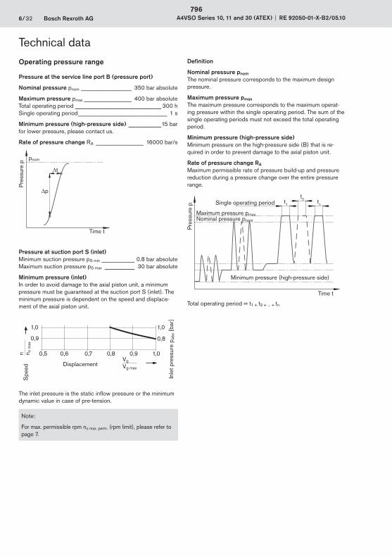
6/32 Bosch Rexroth AG A4VSO Series 10, 11 and 30 (ATEX) RE 92050-01-X-B2/05.10
Definition
Nominal pressure pnom
The nominal pressure corresponds to the maximum design pressure.
Maximum pressure pmax
The maximum pressure corresponds to the maximum operat-ing pressure within the single operating period. The sum of the single operating periods must not exceed the total operating period.
Minimum pressure (high-pressure side)Minimum pressure on the high-pressure side (B) that is re-quired in order to prevent damage to the axial piston unit.
Rate of pressure change RA
Maximum permissible rate of pressure build-up and pressure reduction during a pressure change over the entire pressure range.
Pre
ssur
e p t1
t2 tnSingle operating period
Minimum pressure (high-pressure side)
Maximum pressure pmaxNominal pressure pnom
Time t
Total operating period = t1 + t2 + ... + tn
Technical data
Operating pressure range
Pressure at the service line port B (pressure port)
Nominal pressure pnom _________________ 350 bar absolute
Maximum pressure pmax ________________ 400 bar absoluteTotal operating period _____________________________ 300 hSingle operating period ______________________________ 1 s
Minimum pressure (high-pressure side) ___________15 barfor lower pressure, please contact us.
Rate of pressure change RA ________________ 16000 bar/s
pnom
t
p
Time t
Pre
ssur
e p
Pressure at suction port S (inlet)Minimum suction pressure pS min ___________ 0.8 bar absoluteMaximum suction pressure pS max __________ 30 bar absolute
Minimum pressure (inlet)In order to avoid damage to the axial piston unit, a minimum pressure must be guaranteed at the suction port S (inlet). The minimum pressure is dependent on the speed and displace-ment of the axial piston unit.
The inlet pressure is the static inflow pressure or the minimum dynamic value in case of pre-tension.
Note:
For max. permissible rpm no max. perm. (rpm limit), please refer to page 7.
1,0
0,9
1,0
0,8
0,5 0,6 0,7 0,8 0,9 1,0
DisplacementVg
Vg max
Spe
edn n o
max
Inle
t pre
ssur
e p a
bs [
bar]
796
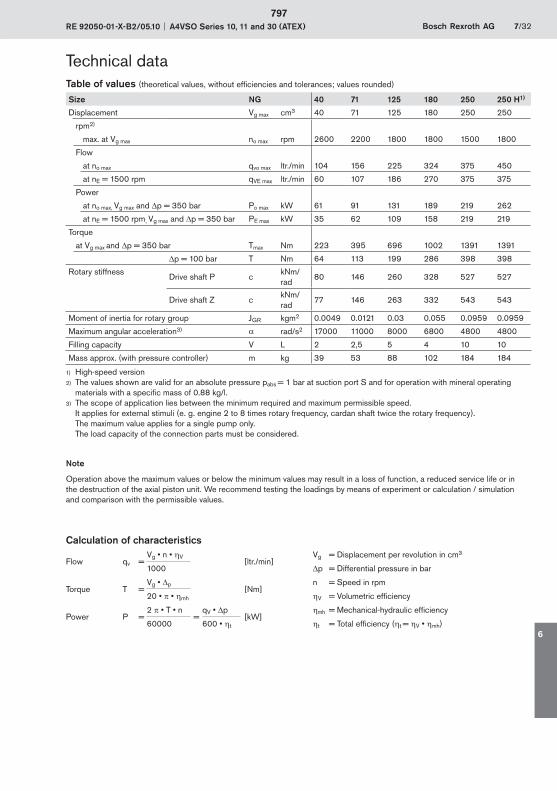
RE 92050-01-X-B2/05.10 A4VSO Series 10, 11 and 30 (ATEX) Bosch Rexroth AG 7/32
Table of values (theoretical values, without efficiencies and tolerances; values rounded)
Size NG 40 71 125 180 250 250 H1)
Displacement Vg max cm3 40 71 125 180 250 250
rpm2)
max. at Vg max no max rpm 2600 2200 1800 1800 1500 1800
Flow
at no max qvo max ltr./min 104 156 225 324 375 450
at nE = 1500 rpm qVE max ltr./min 60 107 186 270 375 375
Power
at no max, Vg max and p = 350 bar Po max kW 61 91 131 189 219 262
at nE = 1500 rpm, Vg max and p = 350 bar PE max kW 35 62 109 158 219 219
Torque
at Vg max and p = 350 bar Tmax Nm 223 395 696 1002 1391 1391
p = 100 bar T Nm 64 113 199 286 398 398
Rotary stiffnessDrive shaft P c
kNm/rad
80 146 260 328 527 527
Drive shaft Z ckNm/rad
77 146 263 332 543 543
Moment of inertia for rotary group JGR kgm2 0.0049 0.0121 0.03 0.055 0.0959 0.0959
Maximum angular acceleration3) rad/s2 17000 11000 8000 6800 4800 4800
Filling capacity V L 2 2,5 5 4 10 10
Mass approx. (with pressure controller) m kg 39 53 88 102 184 184
1) High-speed version2) The values shown are valid for an absolute pressure pabs = 1 bar at suction port S and for operation with mineral operating
materials with a specific mass of 0.88 kg/l.3) The scope of application lies between the minimum required and maximum permissible speed.
It applies for external stimuli (e. g. engine 2 to 8 times rotary frequency, cardan shaft twice the rotary frequency).The maximum value applies for a single pump only. The load capacity of the connection parts must be considered.
Note
Operation above the maximum values or below the minimum values may result in a loss of function, a reduced service life or in the destruction of the axial piston unit. We recommend testing the loadings by means of experiment or calculation / simulation and comparison with the permissible values.
Calculation of characteristics
Flow qv =Vg • n • V
[ltr./min]Vg = Displacement per revolution in cm3
1000 p = Differential pressure in bar
Torque T =Vg • p
[Nm]n = Speed in rpm
20 • • mh V = Volumetric efficiency
Power P =2 • T • n
=qV • p
[kW]mh = Mechanical-hydraulic efficiency
60000 600 • t t = Total efficiency ( t = V • mh)
Technical data
797
6
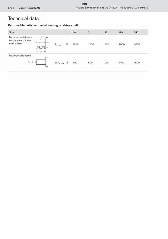
8/32 Bosch Rexroth AG A4VSO Series 10, 11 and 30 (ATEX) RE 92050-01-X-B2/05.10
Technical dataPermissible radial and axial loading on drive shaft
Fax
Size 40 71 125 180 250
Maximum radial force (at distance x/2 from shaft collar) Fq max N 1000 1200 1600 2000 2000
Maximum axial force
± Fax max N 600 800 1000 1400 1800
Fq
X
X/2 X/2
798
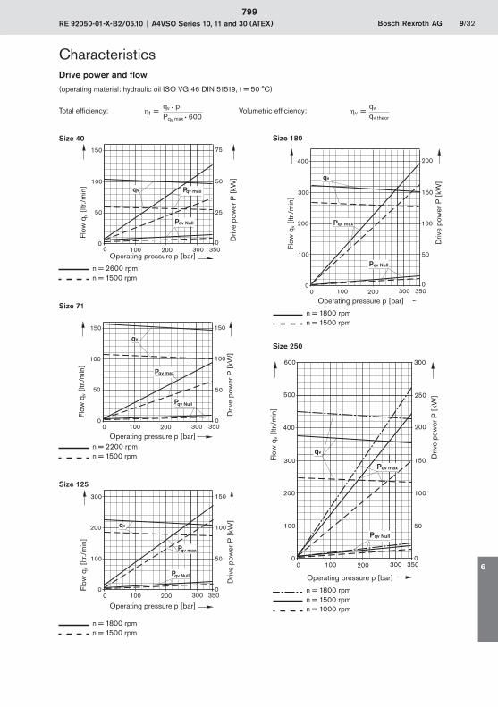
RE 92050-01-X-B2/05.10 A4VSO Series 10, 11 and 30 (ATEX) Bosch Rexroth AG 9/32
CharacteristicsDrive power and flow(operating material: hydraulic oil ISO VG 46 DIN 51519, t = 50 °C)
Total efficiency: t =qv • p Volumetric efficiency: v =
qv
Pqv max • 600 qv theor
Size 40
0 100 200 300 350
2550
0 0
100
150
50
75
Pqv Null
Pqv maxqv
Flow
qv [
ltr./m
in]
Operating pressure p [bar]
Driv
e po
wer
P [
kW]
n = 2600 rpmn = 1500 rpm
Size 71
0 100 200 300 350
5050
0 0
100
150
100
150
qv
Pqv max
Pqv Null
Flow
qv [
ltr./m
in]
Operating pressure p [bar]
Driv
e po
wer
P [
kW]
n = 2200 rpmn = 1500 rpm
Size 125
0 100 200 300 350
50100
0 0
200
300
100
150
qv
Pqv max
Pqv Null
Flow
qv [
ltr./m
in]
Operating pressure p [bar]
Driv
e po
wer
P [
kW]
n = 1800 rpmn = 1500 rpm
Size 180
n = 1800 rpmn = 1500 rpm
Size 250
n = 1800 rpmn = 1500 rpmn = 1000 rpm
0 100 200 300 350
50100
0 0
200
300
100
150
400 200
Pqv max
Pqv Null
qv
Flow
qv [
ltr./m
in]
Operating pressure p [bar]
Driv
e po
wer
P [
kW]
0 100 200 300 350
50100
0 0
200
300
100
150Pqv max
Pqv Null
400
500
200
250
qv
300600
Operating pressure p [bar]
Driv
e po
wer
P [
kW]
Flow
qv [
ltr./m
in]
799
6
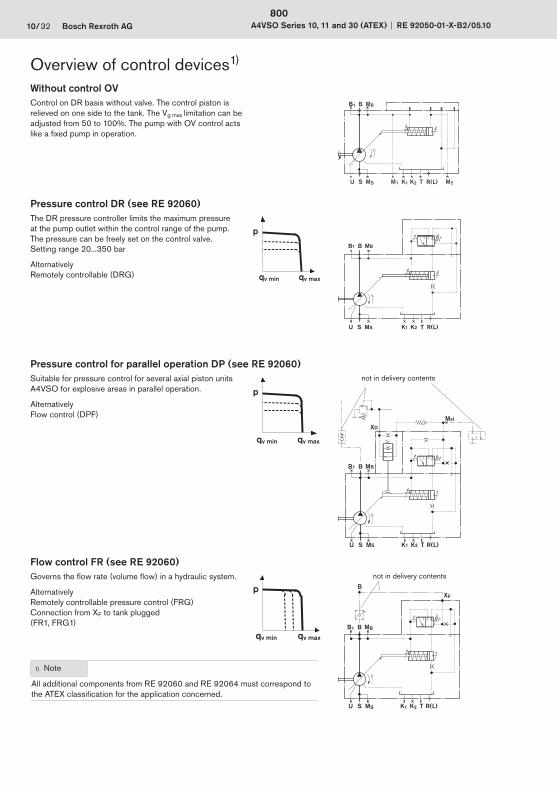
10/32 Bosch Rexroth AG A4VSO Series 10, 11 and 30 (ATEX) RE 92050-01-X-B2/05.10
Overview of control devicesWithout control OVControl on DR basis without valve. The control piston is relieved on one side to the tank. The Vg max limitation can be adjusted from 50 to 100%. The pump with OV control acts like a fixed pump in operation.
R(L)TK2K1
B1 MBB
M2M1U MSS
Pressure control DR (see RE 92060)The DR pressure controller limits the maximum pressure at the pump outlet within the control range of the pump. The pressure can be freely set on the control valve.Setting range 20...350 bar
AlternativelyRemotely controllable (DRG) qv min qv max
p
R(L)TU S MS K1 K2
MBBB1
Pressure control for parallel operation DP (see RE 92060)Suitable for pressure control for several axial piston units A4VSO for explosive areas in parallel operation.
AlternativelyFlow control (DPF)
p
qv min qv max
not in delivery contents
Mst
R(L)TU S MS K1 K2
BB1 MB
XD
Flow control FR (see RE 92060)Governs the flow rate (volume flow) in a hydraulic system.
AlternativelyRemotely controllable pressure control (FRG)Connection from XF to tank plugged (FR1, FRG1)
1) Note
All additional components from RE 92060 and RE 92064 must correspond to the ATEX classification for the application concerned.
p
qv min qv max
not in delivery contents
R(L)TU S MS K1 K2
BB1 MB
XF
B
1)
800
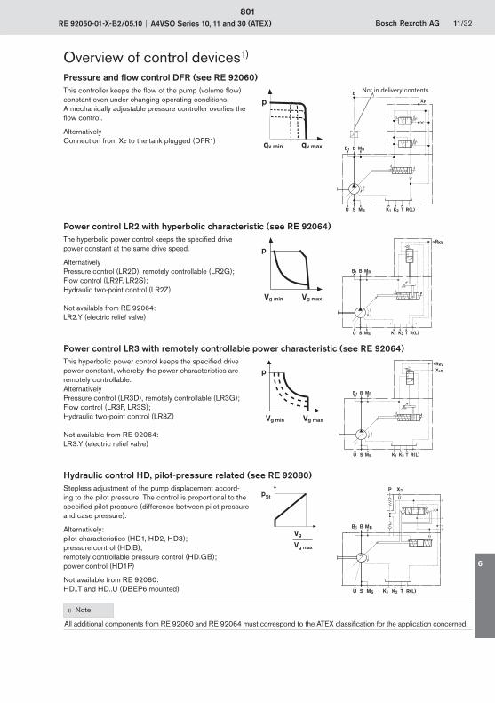
RE 92050-01-X-B2/05.10 A4VSO Series 10, 11 and 30 (ATEX) Bosch Rexroth AG 11/32
Overview of control devices1)
Pressure and flow control DFR (see RE 92060)This controller keeps the flow of the pump (volume flow) constant even under changing operating conditions. A mechanically adjustable pressure controller overlies the flow control.
AlternativelyConnection from XF to the tank plugged (DFR1)
p
qv min qv max
R(L)TU S MS K1 K2
BB1 MB
XF
B Not in delivery contents
Power control LR2 with hyperbolic characteristic (see RE 92064)The hyperbolic power control keeps the specified drive power constant at the same drive speed.
AlternativelyPressure control (LR2D), remotely controllable (LR2G);Flow control (LR2F, LR2S);Hydraulic two-point control (LR2Z)
Not available from RE 92064: LR2.Y (electric relief valve)
Vg min Vg max
p
R(L)TU S MS K1 K2
MBBB1
RKV
Power control LR3 with remotely controllable power characteristic (see RE 92064)This hyperbolic power control keeps the specified drive power constant, whereby the power characteristics are remotely controllable.AlternativelyPressure control (LR3D), remotely controllable (LR3G);Flow control (LR3F, LR3S);Hydraulic two-point control (LR3Z)
Not available from RE 92064:LR3.Y (electric relief valve)
Vg min Vg max
p
R(L)TU S MS K1 K2
MBBB1
RKV
XLR
Hydraulic control HD, pilot-pressure related (see RE 92080)Stepless adjustment of the pump displacement accord-ing to the pilot pressure. The control is proportional to the specified pilot pressure (difference between pilot pressure and case pressure).
Alternatively:pilot characteristics (HD1, HD2, HD3);pressure control (HD.B);remotely controllable pressure control (HD.GB);power control (HD1P)
Not available from RE 92080:HD..T and HD..U (DBEP6 mounted)
Vg
Vg max
pStP
U R(L)TK1 K2MSS
BB1 MB
X2
1) Note
All additional components from RE 92060 and RE 92064 must correspond to the ATEX classification for the application concerned.
801
6
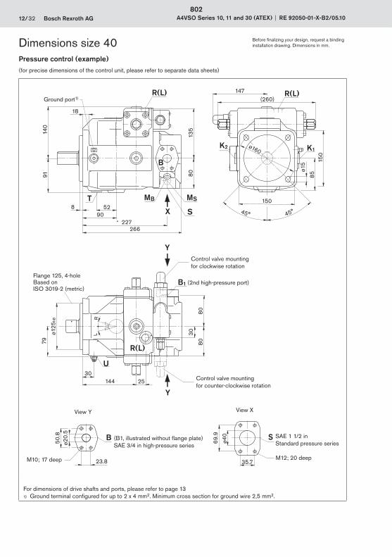
12/32 Bosch Rexroth AG A4VSO Series 10, 11 and 30 (ATEX) RE 92050-01-X-B2/05.10
Pressure control (example)(for precise dimensions of the control unit, please refer to separate data sheets)
X
T MB MS
S
B
K2 K1
U
B1
R(L)
Y
Y
B S
R(L) R(L)
91
90528
140
266227
80
18
(260)
150
85
ø15
150
ø160
147
30144 25
80
30
79
80
ø125
h8
23.8
50.8
ø20.
5
35.7
69.9
ø40
45° 45°
135
15
15
0
LR
For dimensions of drive shafts and ports, please refer to page 131) Ground terminal configured for up to 2 x 4 mm2. Minimum cross section for ground wire 2,5 mm2.
Control valve mountingfor clockwise rotation
Control valve mountingfor counter-clockwise rotation
SAE 1 1/2 inStandard pressure series
M12; 20 deep
View XView Y
M10; 17 deep
(B1, illustrated without flange plate)SAE 3/4 in high-pressure series
(2nd high-pressure port)Flange 125, 4-hole Based on ISO 3019-2 (metric)
Ground port1)
Dimensions size 40 Before finalizing your design, request a binding installation drawing. Dimensions in mm.
802
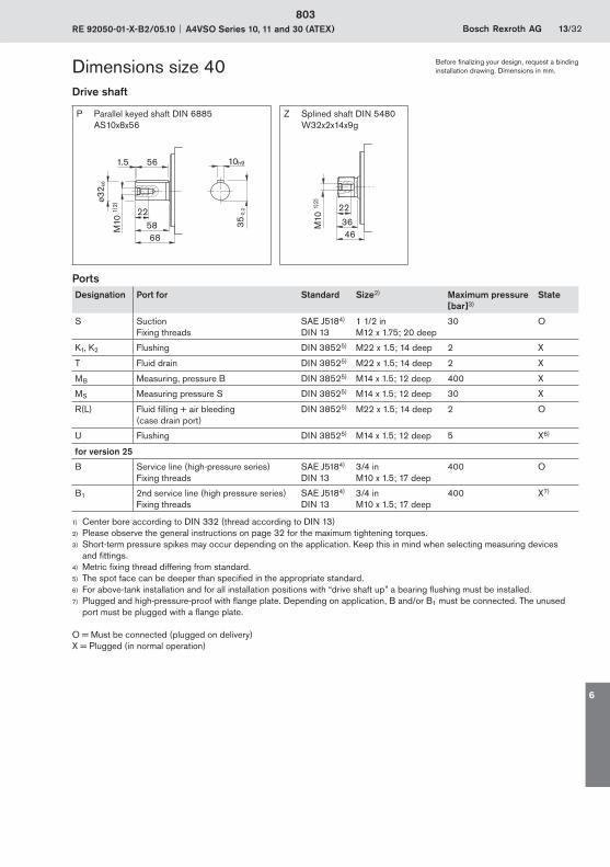
RE 92050-01-X-B2/05.10 A4VSO Series 10, 11 and 30 (ATEX) Bosch Rexroth AG 13/32
Drive shaft
P Parallel keyed shaft DIN 6885 AS10x8x56
Z Splined shaft DIN 5480 W32x2x14x9g
35-0
,2
10h9
M10
1)2)
2258
ø32 k
6
1.5 56
68
36
22
M10
1)2)
46
Ports Desig nation Port for Standard Size2) Maximum pressure
[bar]3)State
S SuctionFixing threads
SAE J5184)
DIN 131 1/2 inM12 x 1.75; 20 deep
30 O
K1, K2 Flushing DIN 38525) M22 x 1.5; 14 deep 2 X
T Fluid drain DIN 38525) M22 x 1.5; 14 deep 2 X
MB Measuring, pressure B DIN 38525) M14 x 1.5; 12 deep 400 X
MS Measuring pressure S DIN 38525) M14 x 1.5; 12 deep 30 X
R(L) Fluid filling + air bleeding(case drain port)
DIN 38525) M22 x 1.5; 14 deep 2 O
U Flushing DIN 38525) M14 x 1.5; 12 deep 5 X6)
for version 25
B Service line (high-pressure series)Fixing threads
SAE J5184)
DIN 133/4 inM10 x 1.5; 17 deep
400 O
B1 2nd service line (high pressure series)Fixing threads
SAE J5184)
DIN 133/4 inM10 x 1.5; 17 deep
400 X7)
1) Center bore according to DIN 332 (thread according to DIN 13)2) Please observe the general instructions on page 32 for the maximum tightening torques.3) Short-term pressure spikes may occur depending on the application. Keep this in mind when selecting measuring devices
and fittings.4) Metric fixing thread differing from standard.5) The spot face can be deeper than specified in the appropriate standard.6) For above-tank installation and for all installation positions with “drive shaft up” a bearing flushing must be installed.7) Plugged and high-pressure-proof with flange plate. Depending on application, B and/or B1 must be connected. The unused
port must be plugged with a flange plate.
O = Must be connected (plugged on delivery)X = Plugged (in normal operation)
Dimensions size 40 Before finalizing your design, request a binding installation drawing. Dimensions in mm.
803
6

14/32 Bosch Rexroth AG A4VSO Series 10, 11 and 30 (ATEX) RE 92050-01-X-B2/05.10
Pressure control (example)(for precise dimensions of the control unit, please refer to separate data sheets)
Y
U
R(L)
B1
Y
K2 K1
MB MS
SX
B
SB
T
R(L) R(L)
ø140
h8
27
92
166 27
92.5
34
92.5
(298)
170
97ø1
5
170
ø180
157
18
106
101618
295254
92.5
42.9
77.8
ø50
27.8
57.2
ø25
152
15
15
0
LR
45° 45°
For dimensions of drive shafts and ports, please refer to page 151) Ground terminal configured for up to 2 x 4 mm2. Minimum cross section for ground wire 2,5 mm2.
Control valve mountingfor clockwise rotation
Control valve mountingfor counter-clockwise rotation
SAE 2 inStandard pressure series
M12; 20 deep
View XView Y
M12; 20 deep
(B1, illustrated without flange plate)SAE 1 in high-pressure series
(2nd high-pressure port)
Flange 140, 4-holeBased on ISO 3019-2 (metric)
Ground port1)
Dimensions size 71 Before finalizing your design, request a binding installation drawing. Dimensions in mm.
804
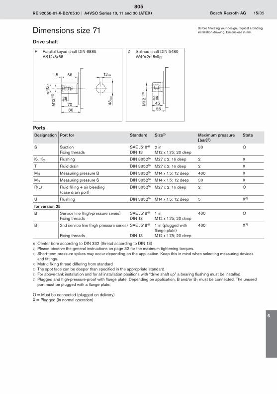
RE 92050-01-X-B2/05.10 A4VSO Series 10, 11 and 30 (ATEX) Bosch Rexroth AG 15/32
Drive shaft
P Parallel keyed shaft DIN 6885 AS12x8x68
Z Splined shaft DIN 5480 W40x2x18x9g
1.5 68
80
M12
1)2)
28
ø40 k
6
70 43-0
,2
12h9
55
28
M12
1)2)
45
Ports Desig nation Port for Standard Size2) Maximum pressure
[bar]3)State
S SuctionFixing threads
SAE J5184)
DIN 132 inM12 x 1.75; 20 deep
30 O
K1, K2 Flushing DIN 38525) M27 x 2; 16 deep 2 X
T Fluid drain DIN 38525) M27 x 2; 16 deep 2 X
MB Measuring pressure B DIN 38525) M14 x 1.5; 12 deep 400 X
MS Measuring pressure S DIN 38525) M14 x 1.5; 12 deep 30 X
R(L) Fluid filling + air bleeding(case drain port)
DIN 38525) M27 x 2; 16 deep 2 O
U Flushing DIN 38525) M14 x 1.5; 12 deep 5 X6)
for version 25
B Service line (high-pressure series)Fixing threads
SAE J5184)
DIN 131 inM12 x 1.75; 20 deep
400 O
B1 2nd service line (high pressure series)
Fixing threads
SAE J5184)
DIN 13
1 in (plugged with flange plate)M12 x 1.75; 20 deep
400 X7)
1) Center bore according to DIN 332 (thread according to DIN 13)2) Please observe the general instructions on page 32 for the maximum tightening torques.3) Short-term pressure spikes may occur depending on the application. Keep this in mind when selecting measuring devices
and fittings.4) Metric fixing thread differing from standard5) The spot face can be deeper than specified in the appropriate standard.6) For above-tank installation and for all installation positions with “drive shaft up” a bearing flushing must be installed.7) Plugged and high-pressure-proof with flange plate. Depending on application, B and/or B1 must be connected. The unused
port must be plugged with a flange plate.
O = Must be connected (plugged on delivery)X = Plugged (in normal operation)
Dimensions size 71 Before finalizing your design, request a binding installation drawing. Dimensions in mm.
805
6
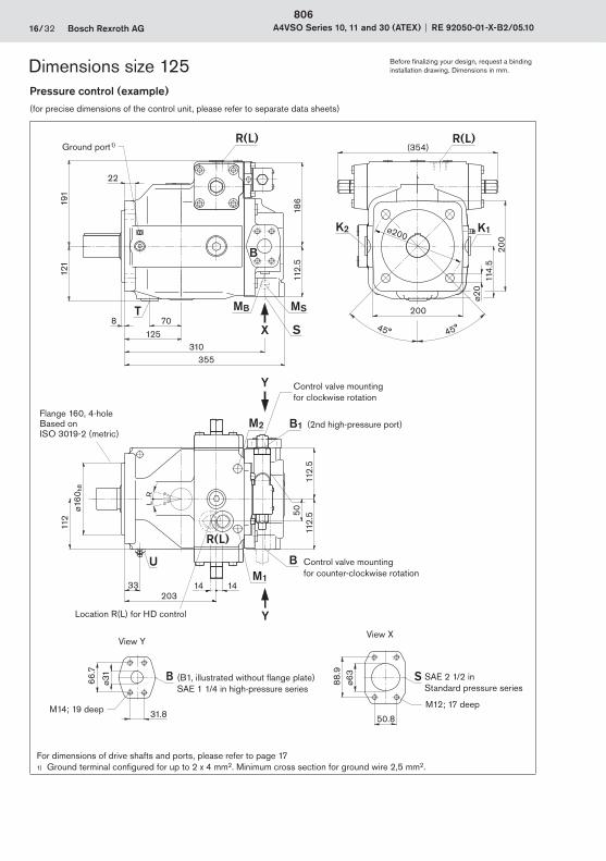
16/32 Bosch Rexroth AG A4VSO Series 10, 11 and 30 (ATEX) RE 92050-01-X-B2/05.10
Pressure control (example)(for precise dimensions of the control unit, please refer to separate data sheets)
B
31.8
66.7
ø31
M2 B1
M1
BU
T MB MS
S
K2 K1
R(L) R(L)
X
Y
Y
R(L)
B
355
191
310
112.
5
22
121
8125
70
5011
2.5
112.
5
33
112
14 14
ø160
h8
ø63
88.9
50.8
S
(354)
ø200
114.
520
0
200
ø20
186
203
15
15
0
LR
45° 45°
For dimensions of drive shafts and ports, please refer to page 171) Ground terminal configured for up to 2 x 4 mm2. Minimum cross section for ground wire 2,5 mm2.
Ground port1)
Dimensions size 125 Before finalizing your design, request a binding installation drawing. Dimensions in mm.
Flange 160, 4-holeBased on ISO 3019-2 (metric)
Control valve mountingfor clockwise rotation
Control valve mountingfor counter-clockwise rotation
SAE 2 1/2 inStandard pressure series
M12; 17 deep
View XView Y
M14; 19 deep
(B1, illustrated without flange plate)SAE 1 1/4 in high-pressure series
(2nd high-pressure port)
Location R(L) for HD control
806

RE 92050-01-X-B2/05.10 A4VSO Series 10, 11 and 30 (ATEX) Bosch Rexroth AG 17/32
Drive shaft
P Parallel keyed shaft DIN 6885 AS14x9x80
Z Splined shaft DIN 5480 W50x2x24x9g
14h91.5
92
3682M
16 1)
2)
ø50 k
6
80
53.5
-0,2 36
6454M
16 1)
2)
Ports Designation Port for Standard Size2) Maximum pressure
[bar]3)State
S SuctionFixing threads
SAE J5184)
DIN 132 1/2 inM12 x 1.75; 18 deep
30 O
K1, K2 Flushing DIN 38525) M33 x 2; 18 deep 2 X
T Fluid drain DIN 38525) M33 x 2; 18 deep 2 X
MB Measuring, pressure B DIN 38525) M14 x 1.5; 12 deep 400 X
MS Measuring pressure S DIN 38525) M14 x 1.5; 12 deep 30 X
R(L) Fluid filling + air bleeding(case drain port)
DIN 38525) M33 x 2; 18 deep 2 O
U Flushing DIN 38525) M14 x 1.5; 12 deep 5 X6)
M1, M2 Measuring control pressure DIN 38525) M14 x 1.5; 12 deep 400 X
for version 25
B Service line (high-pressure series)Fixing threads
SAE J5184)
DIN 131 1/4 inM14 x 2; 19 deep
400 O
B1 2nd service line (high pressure series)
Fixing threads
SAE J5184)
DIN 13
1 1/4 in (plugged with flange plate)M14 x 2; 19 deep
400 X7)
1) Center bore according to DIN 332 (thread according to DIN 13)2) Please observe the general instructions on page 32 for the maximum tightening torques.3) Short-term pressure spikes may occur depending on the application. Keep this in mind when selecting measuring devices
and fittings.4) Metric fixing thread differing from standard5) The spot face can be deeper than specified in the appropriate standard.6) For above-tank installation and for all installation positions with “drive shaft up” a bearing flushing must be installed.7) Plugged and high-pressure-proof with flange plate. Depending on application, B and/or B1 must be connected. The unused
port must be plugged with a flange plate.
O = Must be connected (plugged on delivery)X = Plugged (in normal operation)
Dimensions size 125 Before finalizing your design, request a binding installation drawing. Dimensions in mm.
807
6

18/32 Bosch Rexroth AG A4VSO Series 10, 11 and 30 (ATEX) RE 92050-01-X-B2/05.10
Pressure control (example)(for precise dimensions of the control unit, please refer to separate data sheets)
BUM1
M2 B1
K2 K1
MBSMST
B
R(L)
R(L)
R(L)
X
Y
Y
B
(354)
114.
520
0
200
ø20
ø200
22
375
116
318
121
191
8125
70
112 ø1
60h8
3314 14
120
120
50
66.7
ø31
ø75
106.
4
61.9
S
186
203
31.8
15
15
0
LR
45° 45°
For dimensions of drive shafts and ports, please refer to page 191) Ground terminal configured for up to 2 x 4 mm2. Minimum cross section for ground wire 2,5 mm2.
Flange 160, 4-hole, based on ISO 3019-2 (metric)
Location R(L) for HD control
Control valve mounting for clockwise rotation
Control valve mounting for counter-clockwise rotation
SAE 3 in standard-pressure series
M16; 24 deep
View XView Y
M14; 19 deep
(B1, illustrated without flange plate) SAE 1 1/4 in high-pressure series
(2nd high-pressure port)
Ground port1)
Dimensions size 180 Before finalizing your design, request a binding installation drawing. Dimensions in mm.
808
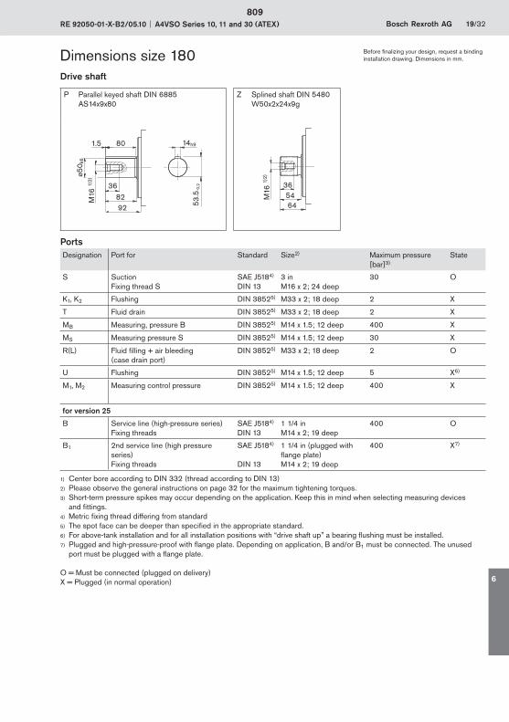
RE 92050-01-X-B2/05.10 A4VSO Series 10, 11 and 30 (ATEX) Bosch Rexroth AG 19/32
Drive shaft
P Parallel keyed shaft DIN 6885 AS14x9x80
Z Splined shaft DIN 5480 W50x2x24x9g
14h91.5
92
3682M
16 1)
2)
ø50 k
6
80
53.5
-0,2 36
6454M
16 1)
2)
Ports Designation Port for Standard Size2) Maximum pressure
[bar]3)State
S SuctionFixing thread S
SAE J5184)
DIN 133 inM16 x 2; 24 deep
30 O
K1, K2 Flushing DIN 38525) M33 x 2; 18 deep 2 X
T Fluid drain DIN 38525) M33 x 2; 18 deep 2 X
MB Measuring, pressure B DIN 38525) M14 x 1.5; 12 deep 400 X
MS Measuring pressure S DIN 38525) M14 x 1.5; 12 deep 30 X
R(L) Fluid filling + air bleeding(case drain port)
DIN 38525) M33 x 2; 18 deep 2 O
U Flushing DIN 38525) M14 x 1.5; 12 deep 5 X6)
M1, M2 Measuring control pressure DIN 38525) M14 x 1.5; 12 deep 400 X
for version 25
B Service line (high-pressure series)Fixing threads
SAE J5184)
DIN 131 1/4 inM14 x 2; 19 deep
400 O
B1 2nd service line (high pressure series)Fixing threads
SAE J5184)
DIN 13
1 1/4 in (plugged with flange plate)M14 x 2; 19 deep
400 X7)
1) Center bore according to DIN 332 (thread according to DIN 13)2) Please observe the general instructions on page 32 for the maximum tightening torques.3) Short-term pressure spikes may occur depending on the application. Keep this in mind when selecting measuring devices
and fittings.4) Metric fixing thread differing from standard5) The spot face can be deeper than specified in the appropriate standard.6) For above-tank installation and for all installation positions with “drive shaft up” a bearing flushing must be installed.7) Plugged and high-pressure-proof with flange plate. Depending on application, B and/or B1 must be connected. The unused
port must be plugged with a flange plate.
O = Must be connected (plugged on delivery)X = Plugged (in normal operation)
Dimensions size 180 Before finalizing your design, request a binding installation drawing. Dimensions in mm.
809
6
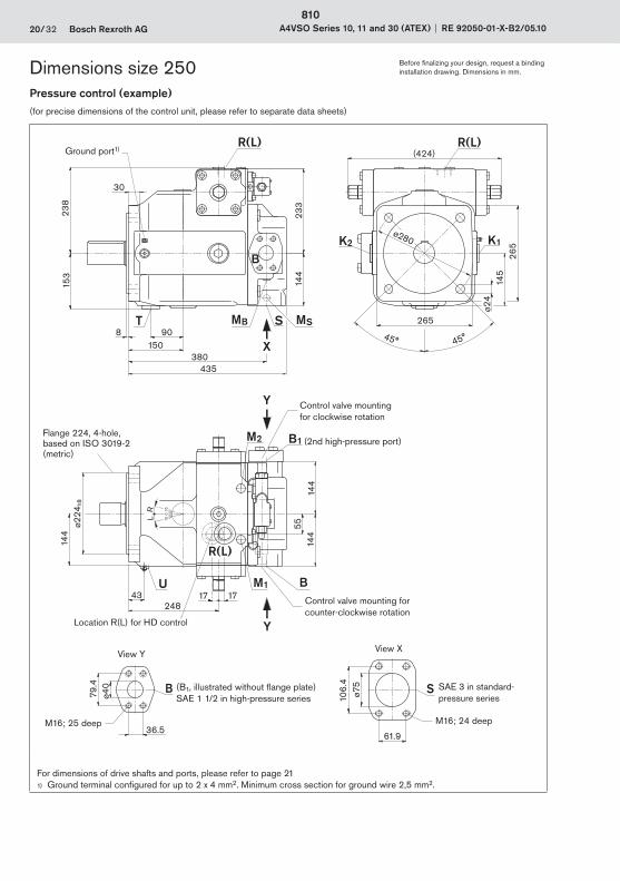
20/32 Bosch Rexroth AG A4VSO Series 10, 11 and 30 (ATEX) RE 92050-01-X-B2/05.10
Pressure control (example)(for precise dimensions of the control unit, please refer to separate data sheets)
K2 K1
T MB MSS
U M1 B
B1M2
B S
R(L)
B
R(L) R(L)
X
Y
Y
380
144
435
30
153
1508 90
ø280
265
145
265
ø24
(424)
43
144
17
5514
4
248
ø224
h8
79.4
36.5
ø40
ø75
106.
4
61.9
144
233
17
238
15
15
0
LR
45° 45°
For dimensions of drive shafts and ports, please refer to page 211) Ground terminal configured for up to 2 x 4 mm2. Minimum cross section for ground wire 2,5 mm2.
Flange 224, 4-hole, based on ISO 3019-2 (metric)
Control valve mounting for clockwise rotation
Control valve mounting for counter-clockwise rotation
SAE 3 in standard-pressure series
M16; 24 deep
View XView Y
M16; 25 deep
(B1, illustrated without flange plate) SAE 1 1/2 in high-pressure series
(2nd high-pressure port)
Location R(L) for HD control
Ground port1)
Dimensions size 250 Before finalizing your design, request a binding installation drawing. Dimensions in mm.
810

RE 92050-01-X-B2/05.10 A4VSO Series 10, 11 and 30 (ATEX) Bosch Rexroth AG 21/32
Drive shaft
P Parallel keyed shaft DIN 6885 AS18x11x100
Z Splined shaft DIN 5480 W60x2x28x9g
3
115
42105M
20 1)
2)
ø60 m
6
100 18h9
64-0
.2
42
8070M
20 1)
2)
Ports Designation Port for Standard Size2) Maximum pressure
[bar]3)State
S SuctionFixing threads
SAE J5184)
DIN 133 inM16 x 2; 24 deep
30 O
K1, K2 Flushing DIN 38525) M42 x 2; 20 deep 2 X
T Fluid drain DIN 38525) M42 x 2; 20 deep 2 X
MB Measuring, pressure B DIN 38525) M14 x 1.5; 12 deep 400 X
MS Measuring pressure S DIN 38525) M14 x 1.5; 12 deep 30 X
R(L) Fluid filling + air bleeding(case drain port)
DIN 38525) M42 x 2; 20 deep 2 O
U Flushing DIN 38525) M14 x 1.5; 12 deep 5 X6)
M1, M2 Measuring control pressure DIN 38525) M18 x 1.5; 12 deep 400 X
for version 25
B Service line (high-pressure series)Fixing threads
SAE J5184)
DIN 131 1/2 inM16 x 2; 25 deep
400 O
B1 2nd service line (high pressure series)
Fixing threads
SAE J5184)
DIN 13
1 1/2 in (plugged with flange plate)M16 x 2; 25 deep
400 X7)
1) Center bore according to DIN 332 (thread according to DIN 13)2) Please observe the general instructions on page 32 for the maximum tightening torques.3) Short-term pressure spikes may occur depending on the application. Keep this in mind when selecting measuring devices
and fittings.4) Metric fixing thread differing from standard5) The spot face can be deeper than specified in the appropriate standard.6) For above-tank installation and for all installation positions with “drive shaft up” a bearing flushing must be installed.7) Plugged and high-pressure-proof with flange plate. Depending on application, B and/or B1 must be connected. The unused
port must be plugged with a flange plate.
O = Must be connected (plugged on delivery)X = Plugged (in normal operation)
Dimensions size 250 Before finalizing your design, request a binding installation drawing. Dimensions in mm.
811
6
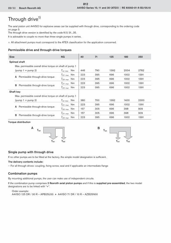
22/32 Bosch Rexroth AG A4VSO Series 10, 11 and 30 (ATEX) RE 92050-01-X-B2/05.10
Through driveThe axial piston unit A4VSO for explosive areas can be supplied with through drive, corresponding to the ordering code on page 3.The through drive version is identified by the code K/U 31...35.
It is advisable to couple no more than three single pumps in series.
1) All attachment pumps must correspond to the ATEX classification for the application concerned.
Permissible drive and through-drive torques
Size NG 40 71 125 180 250
Splined shaft
Max. permissible overall drive torque on shaft of pump 1
(pump 1 + pump 2) Ttot max Nm 446 790 1392 2004 2782
A Permissible through-drive torque TD1 max Nm 223 395 696 1002 1391
TD2 max Nm 223 395 696 1002 1391
B Permissible through-drive torque TD1 max Nm 223 395 696 1002 1391
TD2 max Nm 223 395 696 1002 1391
Shaft key
Max. permissible overall drive torque on shaft of pump 1
(pump 1 + pump 2) Ttot max Nm 380 700 1392 1400 2300
A Permissible through-drive torqueTD1 max Nm 223 395 696 1002 1391
TD2 max Nm 157 305 696 398 909
B Permissible through-drive torqueTD1 max Nm 157 305 696 398 909
TD2 max Nm 223 395 696 1002 1391
Torque distribution
Ttot
TD1 TD2
A
TD1 TD2
TtotB
Single pump with through driveIf no other pumps are to be fitted at the factory, the simple model designation is sufficient.
The delivery contents include:
– For all through drives: coupling, fixing screw, seal and if applicable an intermediate flange
Combination pumpsBy mounting additional pumps, the user can make use of independent circuits.
If the combination pump comprises 2 Rexroth axial piston pumps and if this is supplied pre-assembled, the two model designations are to be linked with “+”.
Order example: A4VSO 125 DR / 30 R – APB25U33 + A4VSO 71 DR / 10 R – AZB25N00
1)
812

RE 92050-01-X-B2/05.10 A4VSO Series 10, 11 and 30 (ATEX) Bosch Rexroth AG 23/32
Overview of attachments
Through drive – A4VSO for explosive areas Attachment for 2nd pump Through drive
Flange Coupling for splined shaft
Short code A4VSO for explosive areas NG (shaft)
Available for NG
Flange, ISO 3019-2 (metric)
125, 4-hole W32x2x14x9g2) K/U31 40 (Z) 40 to 250
140, 4-hole W40x2x18x9g2) K/U33 71 (Z) 71 to 250
160, 4-hole W50x2x24x9g2) U34 125 (Z) 125 to 250
180 (Z) 180 to 250
224, 4-hole W60x2x28x9g2) U35 250 (Z) 250
1) All attachment pumps must correspond to the ATEX classification for the application concerned.2) In accordance with DIN 5480
1)
813
6
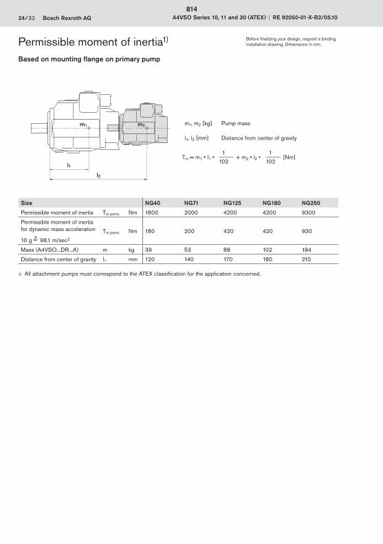
24/32 Bosch Rexroth AG A4VSO Series 10, 11 and 30 (ATEX) RE 92050-01-X-B2/05.10
Permissible moment of inertiaBased on mounting flange on primary pump
l2
l1
m1 m2 m1, m2 [kg] Pump mass
l1, l2 [mm] Distance from center of gravity
Tm = m1 • l1 • 1
+ m2 • l2 • 1
[Nm]102 102
Size NG40 NG71 NG125 NG180 NG250
Permissible moment of inertia Tm perm. Nm 1800 2000 4200 4200 9300
Permissible moment of inertia for dynamic mass acceleration
10 g =̂ 98,1 m/sec2
Tm perm. Nm 180 200 420 420 930
Mass (A4VSO...DR...A) m kg 39 53 88 102 184
Distance from center of gravity l1 mm 120 140 170 180 210
1) All attachment pumps must correspond to the ATEX classification for the application concerned.
Before finalizing your design, request a binding installation drawing. Dimensions in mm.
1)
814
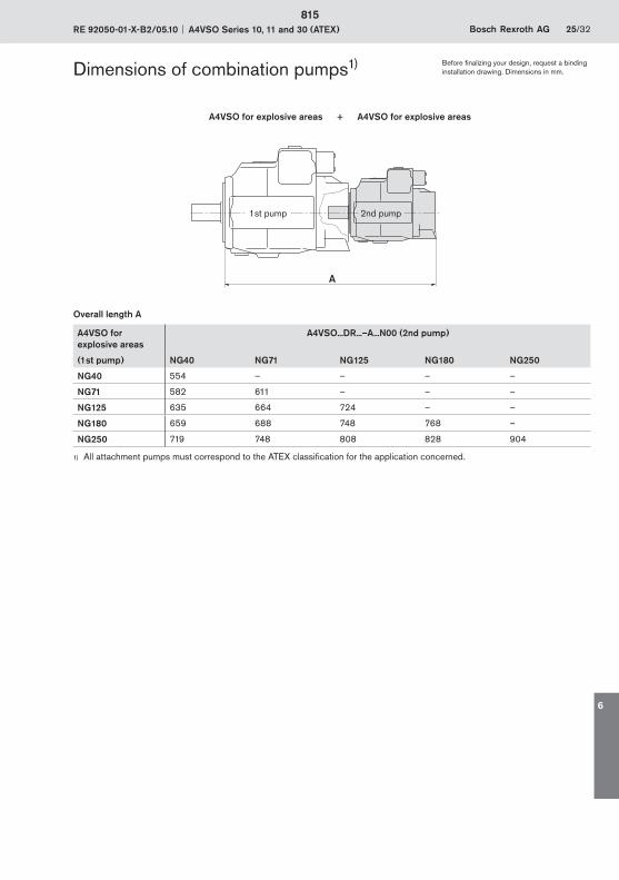
RE 92050-01-X-B2/05.10 A4VSO Series 10, 11 and 30 (ATEX) Bosch Rexroth AG 25/32
Dimensions of combination pumps
A4VSO for explosive areas + A4VSO for explosive areas
A
Overall length A
A4VSO for explosive areas
A4VSO...DR...–A...N00 (2nd pump)
(1st pump) NG40 NG71 NG125 NG180 NG250
NG40 554 – – – –
NG71 582 611 – – –
NG125 635 664 724 – –
NG180 659 688 748 768 –
NG250 719 748 808 828 904
1) All attachment pumps must correspond to the ATEX classification for the application concerned.
Before finalizing your design, request a binding installation drawing. Dimensions in mm.
1)
1st pump 2nd pump
815
6
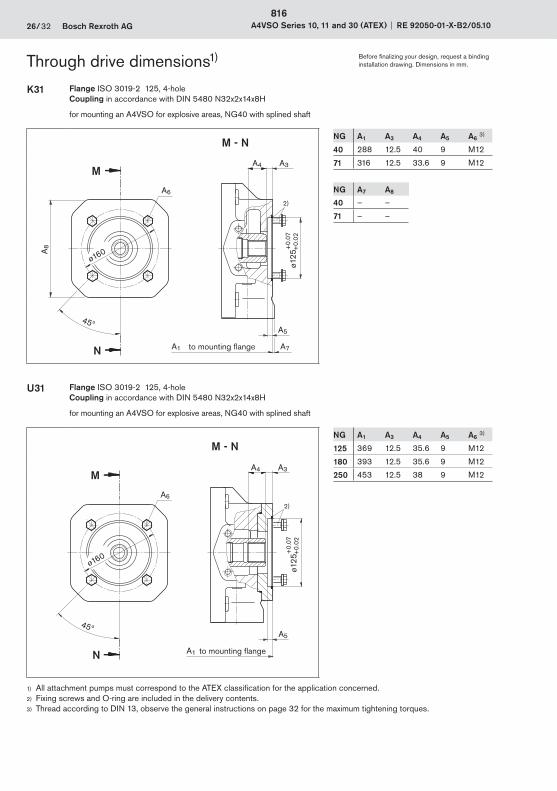
26/32 Bosch Rexroth AG A4VSO Series 10, 11 and 30 (ATEX) RE 92050-01-X-B2/05.10
Through drive dimensions
K31 Flange ISO 3019-2 125, 4-holeCoupling in accordance with DIN 5480 N32x2x14x8H
for mounting an A4VSO for explosive areas, NG40 with splined shaft
M - N
N
M
ø160
45ºA5
A7A1
A4
A8
A6
2)
A3
ø125
+0.
07
+
0.02
to mounting flange
NG A1 A3 A4 A5 A6 3)
40 288 12.5 40 9 M12
71 316 12.5 33.6 9 M12
NG A7 A8
40 – –
71 – –
U31 Flange ISO 3019-2 125, 4-holeCoupling in accordance with DIN 5480 N32x2x14x8H
for mounting an A4VSO for explosive areas, NG40 with splined shaft
M - N
N
M
ø160
45ºA5
A1
A4
A6
2)
A3
ø125
+0.
07
+
0.02
to mounting flange
NG A1 A3 A4 A5 A6 3)
125 369 12.5 35.6 9 M12
180 393 12.5 35.6 9 M12
250 453 12.5 38 9 M12
Before finalizing your design, request a binding installation drawing. Dimensions in mm.
1)
1) All attachment pumps must correspond to the ATEX classification for the application concerned.2) Fixing screws and O-ring are included in the delivery contents.3) Thread according to DIN 13, observe the general instructions on page 32 for the maximum tightening torques.
816

RE 92050-01-X-B2/05.10 A4VSO Series 10, 11 and 30 (ATEX) Bosch Rexroth AG 27/32
Through drive dimensions1)
K33 Flange ISO 3019-2 140, 4-holeCoupling in accordance with DIN 5480 N40x2x18x8H
for mounting an A4VSO for explosive areas, NG71 with splined shaft
N
M
ø180
45º
A8
M - N
A5
A7
A4 A3
A6
ø140
+0.
07
+0.
02
A1
2)
to mounting flange
NG A1 A3 A4 A5 A6 3)
71 316 11.5 42.8 9 M12
NG A7 A8
71 – –
U33 Flange ISO 3019-2 140, 4-holeCoupling in accordance with DIN 5480 N40x2x18x8H
for mounting an A4VSO for explosive areas, NG71 with splined shaft
N
M
A1
2)
ø180
45º
M - N
A5
A4 A3
A6
ø140
+0.
07
+0.
02
to mounting flange
NG A1 A3 A4 A5 A6 3)
125 369 12.5 43.8 9 M12
180 393 12.5 43.8 9 M12
250 453 12.5 48.9 9 M12
Before finalizing your design, request a binding installation drawing. Dimensions in mm.
1) All attachment pumps must correspond to the ATEX classification for the application concerned.2) Fixing screws and O-ring are included in the delivery contents.3) Thread according to DIN 13, observe the general instructions on page 32 for the maximum tightening torques.
817
6
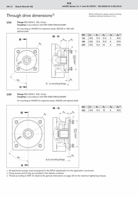
28/32 Bosch Rexroth AG A4VSO Series 10, 11 and 30 (ATEX) RE 92050-01-X-B2/05.10
Through drive dimensions1)
U34 Flange ISO 3019-2 160, 4-holeCoupling in accordance with DIN 5480 N50x2x24x8H
for mounting an A4VSO for explosive areas, NG125 or 180 with splined shaft
A6
N
M
ø200
45º
M - N
A5
A1
A4 A3
+0.
07+
0.02
ø160
2)
to mounting flange
NG A1 A3 A4 A5 A6 3)
125 369 12.5 51.6 9 M16
180 393 12.5 51.6 9 M16
250 453 12.5 54 9 M16
U35 Flange ISO 3019-2 224, 4-holeCoupling in accordance with DIN 5480 N60x2x28x8H
for mounting an A4VSO for explosive areas, NG250 with splined shaft
1)
A6
N
M
ø280
45º
M - N
A5
A1
A4 A3
+0.
10+
0.03
ø224
to mounting flange
NG A1 A3 A4 A5 A6 3)
250 469 12.5 75 9 M20
1) All attachment pumps must correspond to the ATEX classification for the application concerned.2) Fixing screws and O-ring are included in the delivery contents.3) Thread according to DIN 13, observe the general instructions on page 32 for the maximum tightening torques.
Before finalizing your design, request a binding installation drawing. Dimensions in mm.
818

RE 92050-01-X-B2/05.10 A4VSO Series 10, 11 and 30 (ATEX) Bosch Rexroth AG 29/32
Notes
819
6

30/32 Bosch Rexroth AG A4VSO Series 10, 11 and 30 (ATEX) RE 92050-01-X-B2/05.10
Notes
820
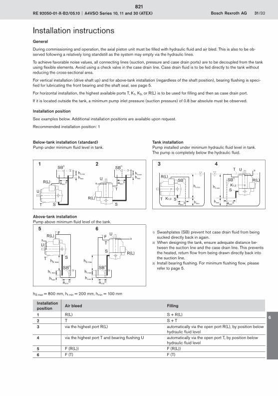
RE 92050-01-X-B2/05.10 A4VSO Series 10, 11 and 30 (ATEX) Bosch Rexroth AG 31/32
Installation instructionsGeneral
During commissioning and operation, the axial piston unit must be filled with hydraulic fluid and air bled. This is also to be ob-served following a relatively long standstill as the system may empty via the hydraulic lines.
To achieve favorable noise values, all connecting lines (suction, pressure and case drain ports) are to be decoupled from the tank using flexible elements. Avoid using a check valve in the case drain line. Case drain fluid is to be fed directly to the tank without reducing the cross-sectional area.
For vertical installation (drive shaft up) and for above-tank installation (regardless of the shaft position), bearing flushing is speci-fied for lubricating the front bearing and the shaft seal, see page 5.
For horizontal installation, the highest available ports T, K1, K2, or R(L) is to be used for filling and then as case drain port.
If it is located outside the tank, a minimum pump inlet pressure (suction pressure) of 0.8 bar absolute must be observed.
Installation position
See examples below. Additional installation positions are available upon request.
Recommended installation position: 1
Below-tank installation (standard)Pump under minimum fluid level in tank.
Tank installationPump installed under minimum hydraulic fluid level in tank. The pump is completely below the hydraulic fluid.
1 2 3 4
Above-tank installationPump above minimum fl uid level of the tank.
5 6U
3)3)
hS max
h t min
hmin
hS max
SBht min
hmin
SB
FF
S
T
T S
R(L)
R(L)
U
1)1)
amin2) amin
2)
1) Swashplates (SB) prevent hot case drain fluid from being sucked directly back in again.
2) When designing the tank, ensure adequate distance be-tween the suction line and the case drain line. This prevents the heated, return flow from being drawn directly back into the suction line.
3) Install bearing flushing. For minimum flushing flow, please refer to page 5.
hS max = 800 mm, ht min = 200 mm, hmin = 100 mm
Installation position
Air bleed Filling
1 R(L) S + R(L)2 T S + T3 via the highest port R(L) automatically via the open port R(L), by position below
hydraulic fluid level4 via the highest port T and bearing flushing U automatically via the open port T, by position below
hydraulic fluid level5 F (R(L)) F (R(L))6 F (T) F (T)
U T
ht min
hmin
ht minhmin
SB SB
R(L)
R(L)
ST S
U
1)
amin2) 3) amin
2)
1)
S
R(L)
T K1,2
K1,2
S
R(L)
T U
hmin
ht min
hmin
ht min
SBSB
3)
1)1)
amin2) amin
2)
821
6
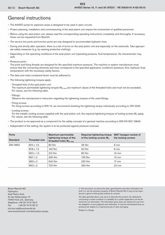
32/32 Bosch Rexroth AG A4VSO Series 10, 11 and 30 (ATEX) RE 92050-01-X-B2/05.10
© This document, as well as the data, specifications and other information set forth in it, are the exclusive property of Bosch Rexroth AG. It may not be repro-duced or given to third parties without its consent.
The data specified above only serve to describe the product. No statements concerning a certain condition or suitability for a certain application can be de-rived from our information. The information given does not release the user from the obligation of own judgment and verification. It must be remembered that our products are subject to a natural process of wear and aging.
Subject to change.
Bosch Rexroth AG HydraulicsAxial Piston UnitsAn den Kelterwiesen 1472160 Horb a.N., GermanyTelephone +49 (0) 74 51 92-0Fax +49 (0) 74 51 82 [email protected]/axial-piston-pumps
General instructions – The A4VSO pump for explosive areas is designed to be used in open circuits.
– Project planning, installation and commissioning of the axial piston unit require the involvement of qualified personnel.
– Before using the axial piston unit, please read the corresponding operating instructions completely and thoroughly. If necessary, these can be requested from Rexroth.
– The service line ports and function ports are only designed to accommodate hydraulic lines.
– During and shortly after operation, there is a risk of burns on the axial piston unit and especially on the solenoids. Take appropri-ate safety measures (e.g. by wearing protective clothing).
– Depending on the operating conditions of the axial piston unit (operating pressure, fluid temperature), the characteristic may shift.
– Pressure ports:The ports and fixing threads are designed for the specified maximum pressure. The machine or system manufacturer must ensure that the connecting elements and lines correspond to the specified application conditions (pressure, flow, hydraulic fluid, temperature) with the necessary safety factors.
– The data and notes contained herein must be adhered to.
– The following tightening torques apply:
- Threaded hole of the axial piston unit: The maximum permissible tightening torques MG max are maximum values of the threaded holes and must not be exceeded. For values, see the following table.
- Fittings: Observe the manufacturer’s instruction regarding the tightening torques of the used fittings.
- Fixing screws: For fixing screws according to DIN 13, we recommend checking the tightening torque individually according to VDI 2230.
- Locking screws: For the metallic locking screws supplied with the axial piston unit, the required tightening torques of locking screws MV apply. For values, see the following table.
– The product is not approved as a component for the safety concept of a general machine according to DIN EN ISO 13849.
– Independent of the setting, the system is to be protected against pressure overload.
Ports Maximum permissible tightening torque of the threaded holes MG max
Required tightening torqueof the locking screws MV
WAF hexagon socket of the locking screws
Standard Threaded size
DIN 3852 M14 x 1.5 80 Nm 35 Nm 6 mm
M18 x 1.5 140 Nm 60 Nm 8 mm
M22 x 1.5 210 Nm 80 Nm 10 mm
M27 x 2 330 Nm 135 Nm 12 mm
M33 x 2 540 Nm 225 Nm 17 mm
M42 x 2 720 Nm 360 Nm 22 mm
822


Bosch Rexroth AG Zum Eisengießer 197816 Lohr, GermanyPhone +49(0)9352/18-0Fax +49(0)9352/[email protected]
Document no.: RE 00112-10Material no.: R999000311Versions no.: 2013-12Replaces: RE 00112-07_2008-11© Bosch Rexroth AG 2013Subject to revisions!
Find your local contact person here:www.boschrexroth.com/contact