Embed Size (px)
Citation preview
Product Data
24ABB3Comfortt13 Air Conditionerwith Puronr Refrigerant1---1/2 to 5 Nominal Tons
Carrier’s Air Conditioners with Puronr refrigerant provide acollection of features unmatched by any other family ofequipment. The 24ABB has been designed utilizing Carrier’snon--ozone depleting Puron refrigerant.
NOTE: Ratings contained in this document are subject tochange at any time. Always refer to the AHRI directory(www.ahridirectory.org) for the most up--to--date ratingsinformation.
INDUSTRY LEADINGFEATURES / BENEFITSEfficiency
S 13 SEER/ up to 11 EER(based on tested combinations)
S Microtube Technologyt refrigeration system
S Indoor air quality accessories available
SoundS Sound level as low as 71 dBA
ComfortS System supports Edger Thermidistatt or standard
thermostat controls
ReliabilityS Non--ozone depleting Puronr refrigerant
S Scroll compressor
S Internal pressure relief valve
S Internal thermal overload
S Filter drier
S Balanced refrigeration system for maximum reliability
DurabilityWeatherArmort protection package:
S Solid, durable sheet metal construction
S Dense wire coil guard
S Baked--on, complete outer coverage, powder paint
ApplicationsS Long--line -- up to 250 feet (76.20 m) total equivalent
length, up to 200 feet (60.96 m) condenser aboveevaporator, or up to 80 ft. (24.38 m) evaporator abovecondenser (See Longline Guide for more information.)
S Low ambient (down to --10_F/--23_C) with accessorykit
2
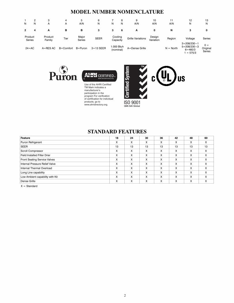
MODEL NUMBER NOMENCLATURE1 2 3 4 5 6 7 8 9 10 11 12 13N N A A A/N N N N A/N A/N A/N N N
2 4 A B B 3 3 6 A 0 N 3 0
ProductSeries
ProductFamily Tier Major
Series SEER CoolingCapacity Grille Variations Design
Variation Region Voltage Series
24=AC A=RES AC B=Comfort B=Puron 3=13 SEER 1.000 Btuh(nominal) A=Dense Grille N = North
3=208/230---15=208/230---36=460/31 = 575/3
0 =OriginalSeries
Use of the AHRI CertifiedTM Mark indicates amanufacturer’s participation in the program For verification of certification for individual products, go to www.ahridirectory.org.
STANDARD FEATURESFeature 18 24 30 36 42 48 60
Puron Refrigerant X X X X X X X
SEER 13 13 13 13 13 13 13
Scroll Compressor X X X X X X X
Field Installed Filter Drier X X X X X X X
Front Seating Service Valves X X X X X X X
Internal Pressure Relief Valve X X X X X X X
Internal Thermal Overload X X X X X X X
Long Line capability X X X X X X X
Low Ambient capability with Kit X X X X X X X
Dense Grille X X X X X X X
X = Standard
3
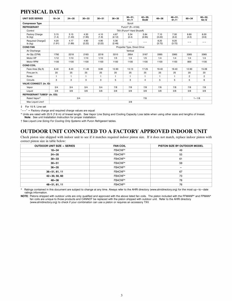
PHYSICAL DATAUNIT SIZE SERIES 18---34 24---35 30---33 30---51 36---35 36---51,
61,1142---30,50,60 48---36 48---51,
61,11 60---34 60---52,62,12
Compressor Type Scroll
REFRIGERANT Puron (R---410A)
Control TXV (Puron Hard Shutoff)
Factory Chargelb (kg)
3.15(1.4)
3.15(1.43)
4.30(1.95)
4.10(1.9)
4.67(2.12)
5.34(2.4)
5.84(2.65)
7.10(3.22)
7.00(3.2)
8.80(4.0)
8.00(3.6)
Required Charge}lb (kg)
4.20(1.91)
4.17(1.89)
4.90(2.22)
4.90(2.22)
5.36(2.48) --- --- --- --- 8.20
(3.72)8.20(3.72) --- --- --- ---
COND FAN Propeller Type, Direct Drive
Air Discharge Vertical
Air Qty (CFM) 1792 2218 2163 2218 3310 2954 3167 3365 3365 3365 3365
Motor HP 1/12 1/10 1/10 1/10 1/5 1/4 1/5 1/4 1/4 1/4 1/4
Motor RPM 1100 1100 1100 1100 1100 1100 1100 1100 1100 800 1100
COND COILFace Area (Sq ft) 8.40 8.40 11.49 9.80 12.93 13.13 17.25 19.40 19.40 12.93 15.09
Fins per In. 20 25 25 25 20 25 25 25 25 20 20
Rows 1 1 1 1 1 1 1 1 1 2 2
Circuits 3 3 3 3 5 3 4 5 5 5 6
VALVE CONNECT. (In. ID)Vapor 3/4 3/4 3/4 3/4 7/8 7/8 7/8 7/8 7/8 7/8 7/8
Liquid 3/8 3/8 3/8 3/8 3/8 3/8 3/8 3/8 3/8 3/8 3/8
REFRIGERANT TUBES* (In. OD)Rated Vapor* 3/4 7/8 1---1/8
Max Liquid Line{ 3/8
} For 15 ft. Line set“--- ---” = Factory charge and required charge values are equal* Units are rated with 25 ft (7.6 m) of lineset length. See Vapor Line Sizing and Cooling Capacity Loss table when using other sizes and lengths of lineset.Note: See unit Installation Instruction for proper installation.
{ See Liquid Line Sizing For Cooling Only Systems with Puron Refrigerant tables.
OUTDOOR UNIT CONNECTED TO A FACTORY APPROVED INDOOR UNITCheck piston size shipped with indoor unit to see if it matches required indoor piston size. If it does not match, replace indoor piston withcorrect piston size in table below:
OUTDOOR UNIT SIZE --- SERIES FAN COIL PISTON SIZE BY OUTDOOR MODEL
18---34 FB4CNF* 49
24---35 FB4CNF* 55
30---33 FB4CNF* 61
30---51 FB4CNF* 59
36---35 FB4CNF* ---
36---51, 61, 11 FB4CNF* 67
42---30, 50, 60 FB4CNF* 73
48---36 FB4CNF* 78
48---51, 61, 11 FB4CNF* 76
* Ratings contained in this document are subject to change at any time. Always refer to the AHRI directory (www.ahridirectory.org) for the most up---to---dateratings information.
NOTE: Pistons shipped with outdoor units are only qualified and approved with the above listed fan coils. The piston included with the FFMANP* and FPMAN*fan coils are unique to those products and CANNOT be replaced with the piston shipped with outdoor unit. Refer to the AHRI directory(www.ahridirectory.org) to check if your combination can use a piston or requires an accessory TXV.

4
REFRIGERANT PIPING LENGTH LIMITATIONSLiquid Line Sizing and Maximum Total Equivalent Lengths{ for Cooling Only Systems with Puronr Refrigerant:The maximum allowable length of a residential split system depends on the liquid line diameter and vertical separation between indoor andoutdoor units.
See Table below for liquid line sizing and maximum lengths :
Maximum Total Equivalent LengthOutdoor Unit BELOW Indoor Unit
Size Liquid LineConnection
LiquidLineDiam.w/ TXV
AC with Puron RefrigerantMaximum Total Equivalent Length{: Outdoor unit BELOW Indoor
Vertical Separation ft (m)0---5(0---1.5)
6---10(1.8---3.0)
11---20(3.4---6.1)
21---30(6.4---9.1)
31---40(9.4---12.2)
41---50(12.5---15.2)
51---60(15.5---18.3)
61---70(18.6---21.3)
71---80(21.6---24.4)
18 3/81/4 150 150 125 100 100 75 --- --- --- --- --- ---5/16 250* 250* 250* 250* 250* 250* 250* 225* 1503/8 250* 250* 250* 250* 250* 250* 250* 250* 250*
24 3/81/4 75 75 75 50 50 --- --- --- --- --- --- --- ---5/16 250* 250* 250* 250* 250* 225* 175 125 1003/8 250* 250* 250* 250* 250* 250* 250* 250* 250*
30 3/81/4 30 --- --- --- --- --- --- --- --- --- --- --- --- --- --- --- ---5/16 175 225* 200 175 125 100 75 --- --- --- ---3/8 250* 250* 250* 250* 250* 250* 250* 250* 250*
36 3/85/16 175 150 150 100 100 100 75 --- --- --- ---3//8 250* 250* 250* 250* 250* 250* 250* 250* 250*
42 3/85/16 125 100 100 75 75 50 --- --- --- --- --- ---3/8 250* 250* 250* 250* 250* 250* 250* 250* 150
48 3/8 3/8 250* 250* 250* 250* 250* 250* 230 160 --- ---60 3/8 3/8 250* 250* 250* 225* 190 150 110 --- --- --- ---
* Maximum actual length not to exceed 200 ft (61 m){ Total equivalent length accounts for losses due to elbows or fitting. See the Long Line Guideline for details.--- --- = outside acceptable range
Maximum Total Equivalent LengthOutdoor Unit ABOVE Indoor Unit
Size Liquid LineConnection
LiquidLineDiam.w/ TXV
AC with Puron RefrigerantMaximum Total Equivalent Length{: Outdoor unit ABOVE Indoor
Vertical Separation ft (m)25(7.6)
26---50(7.9---15.2)
51---75(15.5---22.9)
76---100(23.2---30.5)
101---125(30.8---38.1)
126---150(38.4---45.7)
151---175(46.0---53.3)
176---200(53.6---61.0)
18 3/81/4 175 250* 250* 250* 250* 250* 250* 250*5/16 250* 250* 250* 250* 250* 250* 250* 250*3/8 250* 250* 250* 250* 250* 250* 250* 250*
24 3/81/4 100 125 175 200 225* 250* 250* 250*5/16 250* 250* 250* 250* 250* 250* 250* 250*3/8 250* 250* 250* 250* 250* 250* 250* 250*
30 3/81/4 30 --- --- --- --- --- --- --- --- --- --- --- --- --- ---5/16 250* 250* 250* 250* 250* 250* 250* 250*3/8 250* 250* 250* 250* 250* 250* 250* 250*
36 3/85/16 225* 250* 250* 250* 250* 250* 250* 250*3/8 250* 250* 250* 250* 250* 250* 250* 250*
42 3/85/16 175 200 250* 250* 250* 250* 250* 250*3/8 250* 250* 250* 250* 250* 250* 250* 250*
48 3/8 3/8 250* 250* 250* 250* 250* 250* 250* 250*60 3/8 3/8 250* 250* 250* 250* 250* 250* 250* 250*
* Maximum actual length not to exceed 200 ft (61 m){ Total equivalent length accounts for losses due to elbows or fitting. See the Long Line Guideline for details.--- --- = outside acceptable range
5
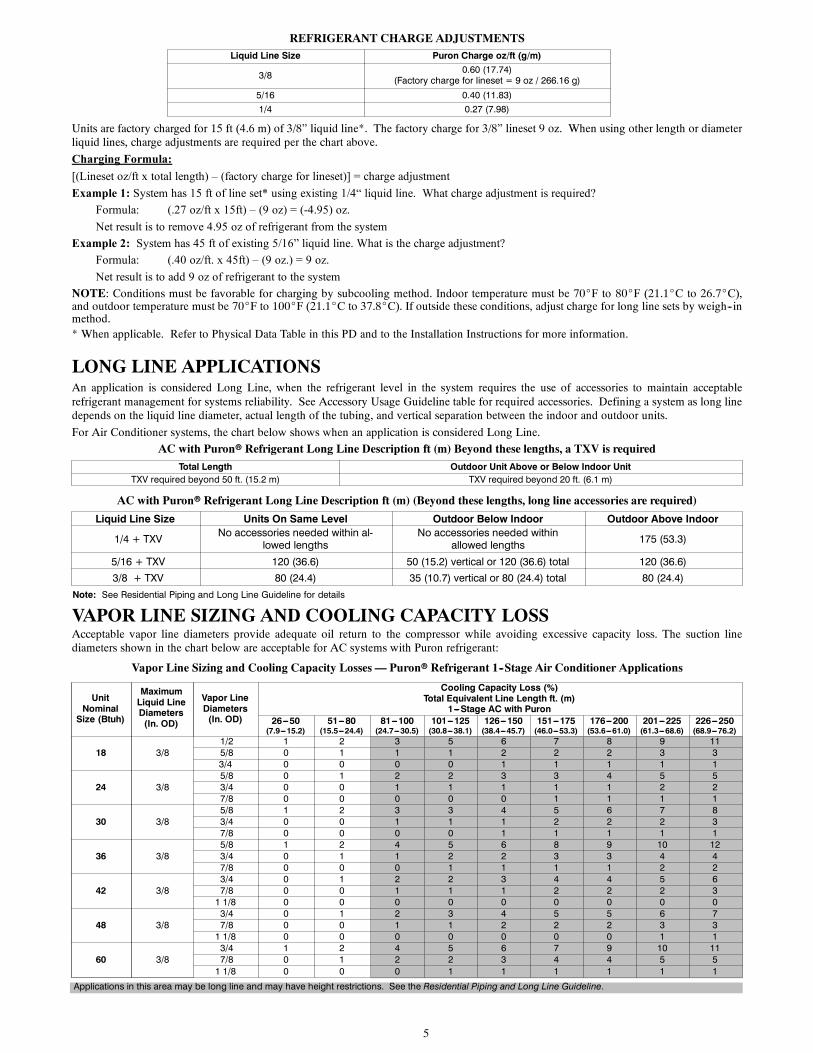
REFRIGERANT CHARGE ADJUSTMENTSLiquid Line Size Puron Charge oz/ft (g/m)
3/8 0.60 (17.74)(Factory charge for lineset = 9 oz / 266.16 g)
5/16 0.40 (11.83)1/4 0.27 (7.98)
Units are factory charged for 15 ft (4.6 m) of 3/8” liquid line*. The factory charge for 3/8” lineset 9 oz. When using other length or diameterliquid lines, charge adjustments are required per the chart above.
Charging Formula:
[(Lineset oz/ft x total length) – (factory charge for lineset)] = charge adjustment
Example 1: System has 15 ft of line set* using existing 1/4“ liquid line. What charge adjustment is required?
Formula: (.27 oz/ft x 15ft) – (9 oz) = (-4.95) oz.
Net result is to remove 4.95 oz of refrigerant from the system
Example 2: System has 45 ft of existing 5/16” liquid line. What is the charge adjustment?
Formula: (.40 oz/ft. x 45ft) – (9 oz.) = 9 oz.
Net result is to add 9 oz of refrigerant to the system
NOTE: Conditions must be favorable for charging by subcooling method. Indoor temperature must be 70_F to 80_F (21.1_C to 26.7_C),and outdoor temperature must be 70_F to 100_F (21.1_C to 37.8_C). If outside these conditions, adjust charge for long line sets by weigh--inmethod.* When applicable. Refer to Physical Data Table in this PD and to the Installation Instructions for more information.
LONG LINE APPLICATIONSAn application is considered Long Line, when the refrigerant level in the system requires the use of accessories to maintain acceptablerefrigerant management for systems reliability. See Accessory Usage Guideline table for required accessories. Defining a system as long linedepends on the liquid line diameter, actual length of the tubing, and vertical separation between the indoor and outdoor units.
For Air Conditioner systems, the chart below shows when an application is considered Long Line.
AC with Puronr Refrigerant Long Line Description ft (m) Beyond these lengths, a TXV is required
Total Length Outdoor Unit Above or Below Indoor UnitTXV required beyond 50 ft. (15.2 m) TXV required beyond 20 ft. (6.1 m)
AC with Puronr Refrigerant Long Line Description ft (m) (Beyond these lengths, long line accessories are required)
Liquid Line Size Units On Same Level Outdoor Below Indoor Outdoor Above Indoor
1/4 + TXV No accessories needed within al-lowed lengths
No accessories needed withinallowed lengths 175 (53.3)
5/16 + TXV 120 (36.6) 50 (15.2) vertical or 120 (36.6) total 120 (36.6)3/8 + TXV 80 (24.4) 35 (10.7) vertical or 80 (24.4) total 80 (24.4)
Note: See Residential Piping and Long Line Guideline for details
VAPOR LINE SIZING AND COOLING CAPACITY LOSSAcceptable vapor line diameters provide adequate oil return to the compressor while avoiding excessive capacity loss. The suction linediameters shown in the chart below are acceptable for AC systems with Puron refrigerant:
Vapor Line Sizing and Cooling Capacity Losses — Puronr Refrigerant 1--Stage Air Conditioner Applications
UnitNominalSize (Btuh)
MaximumLiquid LineDiameters(In. OD)
Vapor LineDiameters(In. OD)
Cooling Capacity Loss (%)Total Equivalent Line Length ft. (m)
1---Stage AC with Puron26---50(7.9---15.2)
51---80(15.5---24.4)
81---100(24.7---30.5)
101---125(30.8---38.1)
126---150(38.4---45.7)
151---175(46.0---53.3)
176---200(53.6---61.0)
201---225(61.3---68.6)
226---250(68.9---76.2)
18 3/81/2 1 2 3 5 6 7 8 9 115/8 0 1 1 1 2 2 2 3 33/4 0 0 0 0 1 1 1 1 1
24 3/85/8 0 1 2 2 3 3 4 5 53/4 0 0 1 1 1 1 1 2 27/8 0 0 0 0 0 1 1 1 1
30 3/85/8 1 2 3 3 4 5 6 7 83/4 0 0 1 1 1 2 2 2 37/8 0 0 0 0 1 1 1 1 1
36 3/85/8 1 2 4 5 6 8 9 10 123/4 0 1 1 2 2 3 3 4 47/8 0 0 0 1 1 1 1 2 2
42 3/83/4 0 1 2 2 3 4 4 5 67/8 0 0 1 1 1 2 2 2 31 1/8 0 0 0 0 0 0 0 0 0
48 3/83/4 0 1 2 3 4 5 5 6 77/8 0 0 1 1 2 2 2 3 31 1/8 0 0 0 0 0 0 0 1 1
60 3/83/4 1 2 4 5 6 7 9 10 117/8 0 1 2 2 3 4 4 5 51 1/8 0 0 0 1 1 1 1 1 1
Applications in this area may be long line and may have height restrictions. See the Residential Piping and Long Line Guideline.
6
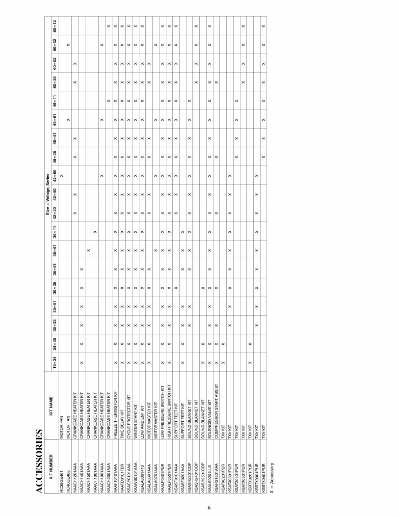
ACCESSORIES
KITNUMBER
KITNAME
Size---Voltage,Series
18---34
24---35
30---33
30---51
36---35
36---51
36---61
36---11
42---30
42---50
42---60
48---36
48---51
48---61
48---11
60---34
60---52
60---62
60---12
HC38GE461
MOTOR,FAN
X
HC40GE466
MOTOR,FAN
XX
KAACH1201AAA
CRANKCASEHEATERKIT
XX
XX
XX
KAACH1401AAA
CRANKCASEHEATERKIT
XX
XX
XX
KAACH1501AAA
CRANKCASEHEATERKIT
X
KAACH1801AAA
CRANKCASEHEATERKIT
X
KAACH1901AAA
CRANKCASEHEATERKIT
XX
X
KAACH2001AAA
CRANKCASEHEATERKIT
XX
KAAFT0101AAA
FREEZETHERMISTORKIT
XX
XX
XX
XX
XX
XX
XX
XX
XX
X
KAATD0101TDR
TIMEDELAYKIT
XX
XX
XX
XX
XX
XX
XX
XX
XX
X
KSACY0101AAA
CYCLEPROTECTORKIT
XX
XX
XX
XX
XX
XX
XX
XX
XX
X
KAAWS0101AAA
WINTERSTARTKIT
XX
XX
XX
XX
XX
XX
XX
XX
XX
X
KSALA0301410
LOWAMBIENTKIT
XX
XX
XX
XX
XX
XX
XX
XX
XX
X
KSALA0601AAA
MOTORMASTERKIT
XX
XX
XX
XX
XX
XX
KSALA0701AAA
MOTORMASTERKIT
XX
XX
KAALP0401PUR
LOWPRESSURESWITCHKIT
XX
XX
XX
XX
XX
XX
XX
XX
XX
X
KAALP0501PUR
HIGHPRESSURESWITCHKIT
XX
XX
XX
XX
XX
XX
XX
XX
XX
X
KSASF0101AAA
SUPPORTFEETKIT
XX
XX
XX
XX
XX
XX
KSASF0201AAA
SUPPORTFEETKIT
XX
XX
XX
X
KSASH2301COP
SOUNDBLANKETKIT
XX
XX
XX
XX
XX
XX
KSASH2401COP
SOUNDBLANKETKIT
XX
XX
KSASH2501COP
SOUNDBLANKETKIT
XX
X
KAALS0201LLS
SOLENOIDVALVEKIT
XX
XX
XX
XX
XX
XX
XX
XX
XX
X
KSAHS1501AAA
COMPRESSORSTARTASSIST
XX
XX
XX
X
KSATX0201PUR
TXVKIT
XX
KSATX0301PUR
TXVKIT
XX
XX
XX
XX
X
KSATX0401PUR
TXVKIT
XX
XX
KSATX0501PUR
TXVKIT
XX
XX
KSBTX0201PUR
TXVKIT
XX
KSBTX0301PUR
TXVKIT
XX
XX
XX
XX
X
KSBTX0401PUR
TXVKIT
XX
XX
XX
XX
X=Accessory
7
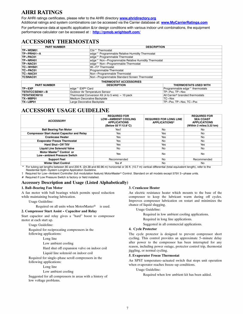
AHRI RATINGSFor AHRI ratings certificates, please refer to the AHRI directory www.ahridirectory.orgAdditional ratings and system combinations can be accessed via the Carrier database at: www.MyCarrierRatings.comFor performance data at specific application &/or design conditions with various indoor unit combinations, the equipmentperformance calculator can be accessed at : http://rpmob.wrightsoft.com/
ACCESSORY THERMOSTATSPART NUMBER DESCRIPTION
TP---WEM01 Côr ThermostatTP---PRH01---A edge Programmable Relative Humidity ThermostatTP---PAC01 edge Programmable ThermostatTP---NRH01 edge Non---Programmable Relative Humidity ThermostatTP---NAC01 edge Non---Programmable ThermostatTC---WHS01 Wi---Fi ThermostatTC---PAC01 Programmable ThermostatTC---NAC01 Non---Programmable ThermostatTCSNAC01 Non---Programmable Standard Screen Thermostat
THERMOSTAT ACCESSORIESPART NUMBER DESCRIPTION THERMOSTATS USED WITH
TP---EXP edge EXP Card Programmable edge thermostatsTSTATCCSEN01---B Outdoor Air Temperature Sensor TP---Pxx, TP---NxxTSTATXXCNV10 Thermostat Conversion Kit (4 to 5 wire) --- 10 pack All Carrier branded thermostatsTX---MBP01 Medium Decorative Backplate TC---NxxTX---LBP01 Large Decorative Backplate TP---Pxx, TP---Nxx, TC---Pxx
ACCESSORY USAGE GUIDELINE
ACCESSORY
REQUIRED FORLOW---AMBIENT COOLING
APPLICATIONS(Below 55F/12.8_C)
REQUIRED FOR LONG LINEAPPLICATIONS*
REQUIRED FORSEA COASTAPPLICATIONS
(Within 2 miles/3.22 km)Ball Bearing Fan Motor Yes{ No No
Compressor Start Assist Capacitor and Relay Yes Yes NoCrankcase Heater Yes Yes No
Evaporator Freeze Thermostat Yes No NoHard Shut---Off TXV Yes Yes Yes
Liquid Line Solenoid Valve No No NoMotor Master Control or
Low---ambient Pressure Switch Yes No No
Support Feet Recommended No RecommendedWinter Start Control Yes # No No
* For tubing set lengths between 80 and 200 ft. (24.38 and 60.96 m) horizontal or 35 ft. (10.7 m) vertical differential (total equivalent length), refer to theResidential Split ---System Longline Application Guideline.
{ Required for Low---Ambient Controller (full modulation feature) MotorMasterr Control. Standard on all models except 575V 3---phase units.# Required if Low Pressure Switch is factory or field installed.
Accessory Description and Usage (Listed Alphabetically)1. Ball--Bearing Fan MotorA fan motor with ball bearings which permits speed reductionwhile maintaining bearing lubrication.
Usage Guideline:Required on all units when MotorMasterr is used.
2. Compressor Start Assist -- Capacitor and RelayStart capacitor and relay gives a ”hard” boost to compressormotor at each start up.
Usage Guideline:Required for reciprocating compressors in thefollowing applications:
Long lineLow ambient coolingHard shut off expansion valve on indoor coilLiquid line solenoid on indoor coil
Required for single--phase scroll compressors in thefollowing applications:
Long lineLow ambient cooling
Suggested for all compressors in areas with a history oflow voltage problems.
3. Crankcase HeaterAn electric resistance heater which mounts to the base of thecompressor to keep the lubricant warm during off cycles.Improves compressor lubrication on restart and minimizes thechance of liquid slugging.
Usage Guideline:Required in low ambient cooling applications.Required in long line applications.
Suggested in all commercial applications.4. Cycle ProtectorThe cycle protector is designed to prevent compressor shortcycling. This control provides an approximate 5--minute delayafter power to the compressor has been interrupted for anyreason, including power outage, protector control trip, thermostatjiggling, or normal cycling.
5. Evaporator Freeze ThermostatAn SPST temperature--actuated switch that stops unit operationwhen evaporator reaches freeze--up conditions.
Usage Guideline:
Required when low ambient kit has been added.
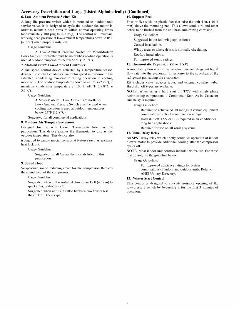
8
Accessory Description and Usage (Listed Alphabetically) (Continued)6. Low--Ambient Pressure Switch KitA long life pressure switch which is mounted to outdoor unitservice valve. It is designed to cycle the outdoor fan motor inorder to maintain head pressure within normal operating limits(approximately 100 psig to 225 psig). The control will maintainworking head pressure at low--ambient temperatures down to 0_F(--18_C) when properly installed.
Usage Guideline:
A Low--Ambient Pressure Switch or MotorMasterrLow--Ambient Controller must be used when cooling operation isused at outdoor temperatures below 55_F (12.8_C).
7. MotorMasterr Low--Ambient ControllerA fan--speed control device activated by a temperature sensor,designed to control condenser fan motor speed in response to thesaturated, condensing temperature during operation in coolingmode only. For outdoor temperatures down to --10_F (--23_C), itmaintains condensing temperature at 100_F 10_F (37.8_C 5.5_C).
Usage Guideline:
A MotorMasterr Low Ambient Controller orLow--Ambient Pressure Switch must be used whencooling operation is used at outdoor temperaturesbelow 55_F (12.8_C).
Suggested for all commercial applications.
8. Outdoor Air Temperature SensorDesigned for use with Carrier Thermostats listed in thispublication. This device enables the thermostat to display theoutdoor temperature. This device also
is required to enable special thermostat features such as auxiliaryheat lock out.
Usage Guideline:
Suggested for all Carrier thermostats listed in thispublication.
9. Sound HoodWraparound sound reducing cover for the compressor. Reducesthe sound level of the compressor.
Usage Guideline:
Suggested when unit is installed closer than 15 ft (4.57 m) toquiet areas, bedrooms, etc.
Suggested when unit is installed between two houses lessthan 10 ft (3.05 m) apart.
10. Support FeetFour or five stick--on plastic feet that raise the unit 4 in. (101.6mm) above the mounting pad. This allows sand, dirt, and otherdebris to be flushed from the unit base, minimizing corrosion.
Usage Guideline:
Suggested in the following applications:
Coastal installations.
Windy areas or where debris is normally circulating.
Rooftop installations.
For improved sound ratings.
11. Thermostatic Expansion Valve (TXV)A modulating flow--control valve which meters refrigerant liquidflow rate into the evaporator in response to the superheat of therefrigerant gas leaving the evaporator.
Kit includes valve, adapter tubes, and external equalizer tube.Hard shut off types are available.
NOTE: When using a hard shut off TXV with single phasereciprocating compressors, a Compressor Start Assist Capacitorand Relay is required.
Usage Guideline:
Required to achieve AHRI ratings in certain equipmentcombinations. Refer to combination ratings.
Hard shut off TXV or LLS required in air conditionerlong line applications.
Required for use on all zoning systems.
12. Time--Delay RelayAn SPST delay relay which briefly continues operation of indoorblower motor to provide additional cooling after the compressorcycles off.
NOTE: Most indoor unit controls include this feature. For thosethat do not, use the guideline below.
Usage Guideline:
For improved efficiency ratings for certaincombinations of indoor and outdoor units. Refer toAHRI Unitary Directory.
13. Winter Start ControlThis control is designed to alleviate nuisance opening of thelow--pressure switch by bypassing it for the first 3 minutes ofoperation.
9
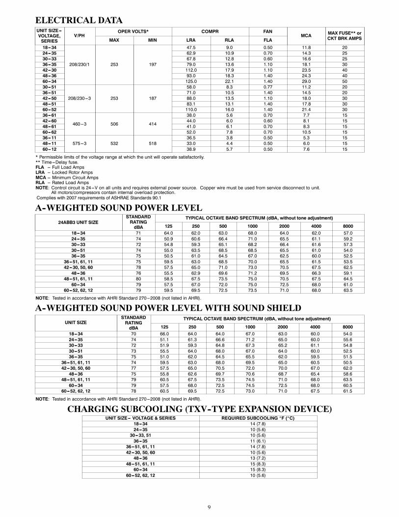
ELECTRICAL DATAUNIT SIZE---VOLTAGE,SERIES
V/PHOPER VOLTS* COMPR FAN
MCA MAX FUSE** orCKT BRK AMPSMAX MIN LRA RLA FLA
18---34
208/230/1 253 197
47.5 9.0 0.50 11.8 2024---35 62.9 10.9 0.70 14.3 2530---33 67.8 12.8 0.60 16.6 2536---35 79.0 13.6 1.10 18.1 3042---30 112.0 17.9 1.10 23.5 4048---36 93.0 18.3 1.40 24.3 4060---34 125.0 22.1 1.40 29.0 5030---51
208/230---3 253 187
58.0 8.3 0.77 11.2 2036---51 71.0 10.5 1.40 14.5 2042---50 88.0 13.5 1.10 18.0 3048---51 83.1 13.1 1.40 17.8 3060---52 110.0 16.0 1.40 21.4 3036---61
460---3 506 414
38.0 5.6 0.70 7.7 1542---60 44.0 6.0 0.60 8.1 1548---61 41.0 6.1 0.70 8.3 1560---62 52.0 7.8 0.70 10.5 1536---11
575---3 532 51836.5 3.8 0.50 5.3 15
48---11 33.0 4.4 0.50 6.0 1560---12 38.9 5.7 0.50 7.6 15
* Permissible limits of the voltage range at which the unit will operate satisfactorily.** Time---Delay fuse.FLA --- Full Load AmpsLRA --- Locked Rotor AmpsMCA --- Minimum Circuit AmpsRLA --- Rated Load AmpsNOTE: Control circuit is 24---V on all units and requires external power source. Copper wire must be used from service disconnect to unit.
All motors/compressors contain internal overload protection.Complies with 2007 requirements of ASHRAE Standards 90.1
A--WEIGHTED SOUND POWER LEVEL
24ABB3 UNIT SIZESTANDARDRATINGdBA
TYPICAL OCTAVE BAND SPECTRUM (dBA, without tone adjustment)
125 250 500 1000 2000 4000 800018---34 71 64.0 62.0 63.0 68.0 64.0 62.0 57.024---35 74 50.9 60.6 66.4 71.0 65.5 61.1 59.230---33 72 54.8 59.3 65.1 68.2 66.4 61.6 57.330---51 74 55.0 63.5 68.5 68.5 65.5 61.0 54.036---35 75 50.5 61.0 64.5 67.0 62.5 60.0 52.5
36---51, 61, 11 75 59.5 63.0 68.5 70.0 65.5 61.5 53.542---30, 50, 60 78 57.5 65.0 71.0 73.0 70.5 67.5 62.548---36 76 55.5 62.9 69.6 71.2 69.5 66.3 59.1
48---51, 61, 11 80 58.5 67.5 73.5 75.0 70.5 67.5 64.560---34 79 57.5 67.0 72.0 75.0 72.5 68.0 61.0
60---52, 62, 12 79 59.5 69.5 72.5 73.5 71.0 68.0 63.5
NOTE: Tested in accordance with AHRI Standard 270---2008 (not listed in AHRI).
A--WEIGHTED SOUND POWER LEVEL WITH SOUND SHIELD
UNIT SIZESTANDARDRATINGdBA
TYPICAL OCTAVE BAND SPECTRUM (dBA, without tone adjustment)
125 250 500 1000 2000 4000 800018---34 70 66.0 64.0 64.0 67.0 63.0 60.0 54.024---35 74 51.1 61.3 66.6 71.2 65.0 60.0 55.630---33 72 51.9 59.3 64.8 67.3 65.2 61.1 54.830---51 73 55.5 64.0 68.0 67.0 64.0 60.0 52.536---35 75 51.0 62.0 64.5 65.5 62.0 59.5 51.5
36---51, 61, 11 74 59.5 63.0 68.0 69.5 65.0 60.5 50.542---30, 50, 60 77 57.5 65.0 70.5 72.0 70.0 67.0 62.048---36 75 55.8 62.6 69.7 70.6 68.7 65.4 58.6
48---51, 61, 11 79 60.5 67.5 73.5 74.5 71.0 68.0 63.560---34 79 57.5 68.0 72.5 74.5 72.5 68.0 60.5
60---52, 62, 12 78 60.5 69.5 72.5 73.0 71.0 67.5 61.5
NOTE: Tested in accordance with AHRI Standard 270---2008 (not listed in AHRI).
CHARGING SUBCOOLING (TXV--TYPE EXPANSION DEVICE)UNIT SIZE--- VOLTAGE & SERIES REQUIRED SUBCOOLING _F (_C)
18---34 14 (7.8)24---35 10 (5.6)30---33, 51 10 (5.6)36---35 11 (6.1)
36---51, 61, 11 14 (7.8)42---30, 50, 60 10 (5.6)48---36 13 (7.2)
48---51, 61, 11 15 (8.3)60---34 15 (8.3)
60---52, 62, 12 10 (5.6)
10
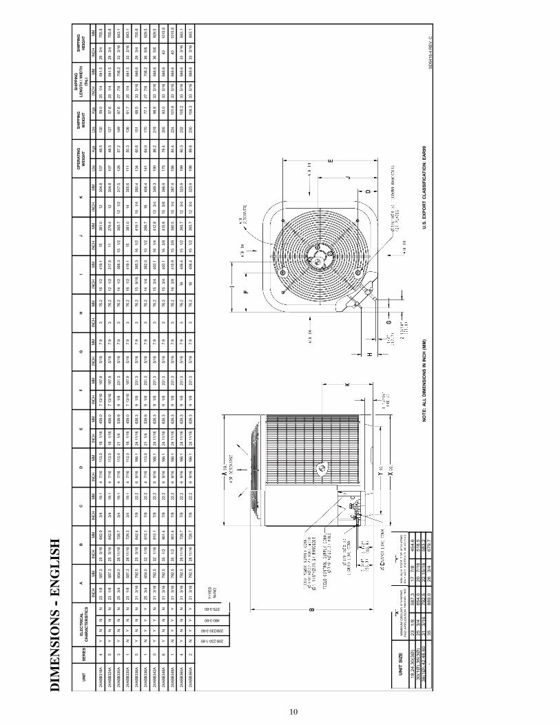
DIM
ENSIONS--ENGLISH
INC
HM
MIN
CH
MM
INC
HM
MIN
CH
MM
INC
HM
MIN
CH
MM
INC
HM
MIN
CH
MM
INC
HM
MIN
CH
MM
INC
HM
MLb
sKg
sLb
sKg
sIN
CH
MM
INC
HM
M
24AB
B318
A4
YN
NN
23
1/8
587.
325
5/
1664
2.9
3/4
19.1
4 7/
1611
3.0
18
1/16
459.
07
13/1
619
7.9
5/16
7.9
376
.216
1/
241
9.1
1538
1.0
1230
4.8
107
48.5
130
59.0
25
1/4
641.
529
3/
475
5.8
24AB
B324
A5
YN
NN
23
1/8
587.
325
5/
1664
2.9
3/4
19.1
4 7/
1611
3.0
18
1/16
459.
07
13/1
619
7.9
5/16
7.9
376
.212
1/
231
7.5
1127
9.4
1230
4.8
107
48.5
127
57.6
25
1/4
641.
529
3/
475
5.8
24AB
B330
A3
YN
NN
25
3/4
654.
028
11/
1672
8.7
3/4
19.1
4 7/
1611
3.0
21
1/4
539.
99
1/8
231.
35/
167.
93
76.2
14
1/2
368.
315
1/
239
3.7
12
1/2
317.
512
657
.214
967
.627
7/
870
8.2
33
3/16
843.
1
24AB
B330
A1
NY
NN
23
1/8
587.
328
11/
1672
9.3
3/4
19.1
4 7/
1611
3.0
18
1/16
459.
07
13/1
619
7.9
5/16
7.9
376
.216
1/
241
9.1
1538
1.0
1435
5.6
111
50.3
136
61.7
25
1/4
641.
533
3/
1684
3.1
24AB
B336
A5
YN
NN
31
3/16
792.
525
5/
1664
2.4
7/8
22.2
6 9/
1616
6.1
24 1
1/16
626.
39
1/8
231.
35/
167.
93
76.2
15
9/16
395.
316
1/
241
9.1
10
1/4
260.
413
460
.815
168
.533
5/
1684
6.6
29
3/4
755.
8
24AB
B336
A1
NY
YY
25
3/4
654.
032
1/
1681
5.1
7/8
22.2
4 7/
1611
3.0
21
1/4
539.
99
1/8
231.
35/
167.
93
76.2
14
1/4
362.
010
1/
226
6.7
1640
6.4
141
64.0
170
77.1
27
7/8
708.
236
5/
892
9.5
24AB
B342
A0
YY
YN
31
3/16
792.
532
1/
1681
5.1
7/8
22.2
6 9/
1616
6.1
24 1
1/16
626.
39
1/8
231.
35/
167.
93
76.2
15
3/4
400.
116
1/
441
2.8
13
3/4
349.
319
086
.221
898
.933
5/
1684
6.6
36
5/8
929.
5
24AB
B348
A6
YN
NN
31
3/16
792.
535
1/
290
1.4
7/8
22.2
6 9/
1616
6.1
24 1
1/16
626.
39
1/8
231.
35/
167.
93
76.2
15
3/4
400.
116
3/
841
5.9
15
5/8
396.
917
579
.420
593
.033
5/
1684
6.6
4010
15.8
24AB
B348
A1
NY
YY
31
3/16
792.
535
1/
290
1.4
7/8
22.2
6 9/
1616
6.1
24 1
1/16
626.
39
1/8
231.
35/
167.
93
76.2
16
3/8
415.
915
3/
839
0.5
15
1/4
387.
418
684
.422
410
1.6
33
5/16
846.
640
1015
.8
24AB
B360
A4
YN
NN
31
3/16
792.
528
11/
1672
8.7
7/8
22.2
6 9/
1616
6.1
24 1
1/16
626.
39
1/8
231.
35/
167.
93
76.2
1640
6.4
15
1/2
393.
712
3/
432
3.9
199
90.3
232
105.
233
5/
1684
6.6
33
3/16
843.
1
24AB
B360
A2
NY
YY
31
3/16
792.
528
11/
1672
8.7
7/8
22.2
6 9/
1616
6.1
24 1
1/16
626.
39
1/8
231.
35/
167.
93
76.2
1640
6.4
15
1/2
393.
712
3/
432
3.9
198
89.8
230
104.
333
5/
1684
6.6
33
3/16
843.
1
GH
IJ
KU
NIT
SER
IES
ELEC
TRIC
ALC
HAR
ACTE
RIS
TIC
SA
BO
PER
ATIN
GW
EIG
HT
SHIP
PIN
GW
EIG
HT
SHIP
PIN
GLE
NG
TH /
WID
TH
(Sq.
)
U.S
. EXP
OR
T C
LASS
IFIC
ATIO
N: E
AR99
208-230-1-60
208/230-3-60
460-3-60
575-3-60
Y=YE
SN=
NO
NO
TE: A
LL D
IMEN
SIO
NS
IN IN
CH
(MM
)
C
SD
5416
-4 R
EV.
C
SHIP
PIN
GH
EIG
HT
DE
F
UN
IT S
IZE
18,2
4,30
(3Ø
)23
1/
858
7.3
17
7/8
454.
630
(1Ø
),36
(3Ø
)25
3/
465
4.0
20
7/16
518.
536
(1Ø
),42
,48,
6031
3/
1679
2.5
22 1
5/16
583.
2-
3588
9.0
26
3/4
679.
7
"Y"
MIN
IMU
M R
OO
F-T
OP
MO
UN
TIN
GP
AD
AP
PLI
CA
TIO
N D
IME
NS
ION
S
"X"
MIN
IMU
M G
RO
UN
D M
OU
NTI
NG
PA
D A
PP
LIC
ATI
ON
DIM
EN
SIO
NS
"Y"
MIN
IMU
MR
OO
F-T
OTTP
MO
UN
TIN
GP
AD
AP
PLI
CA
TIO
ND
IME
NS
ION
S
X" ND
MO
UN
TIN
GN
DIM
EN
SIO
NS
11
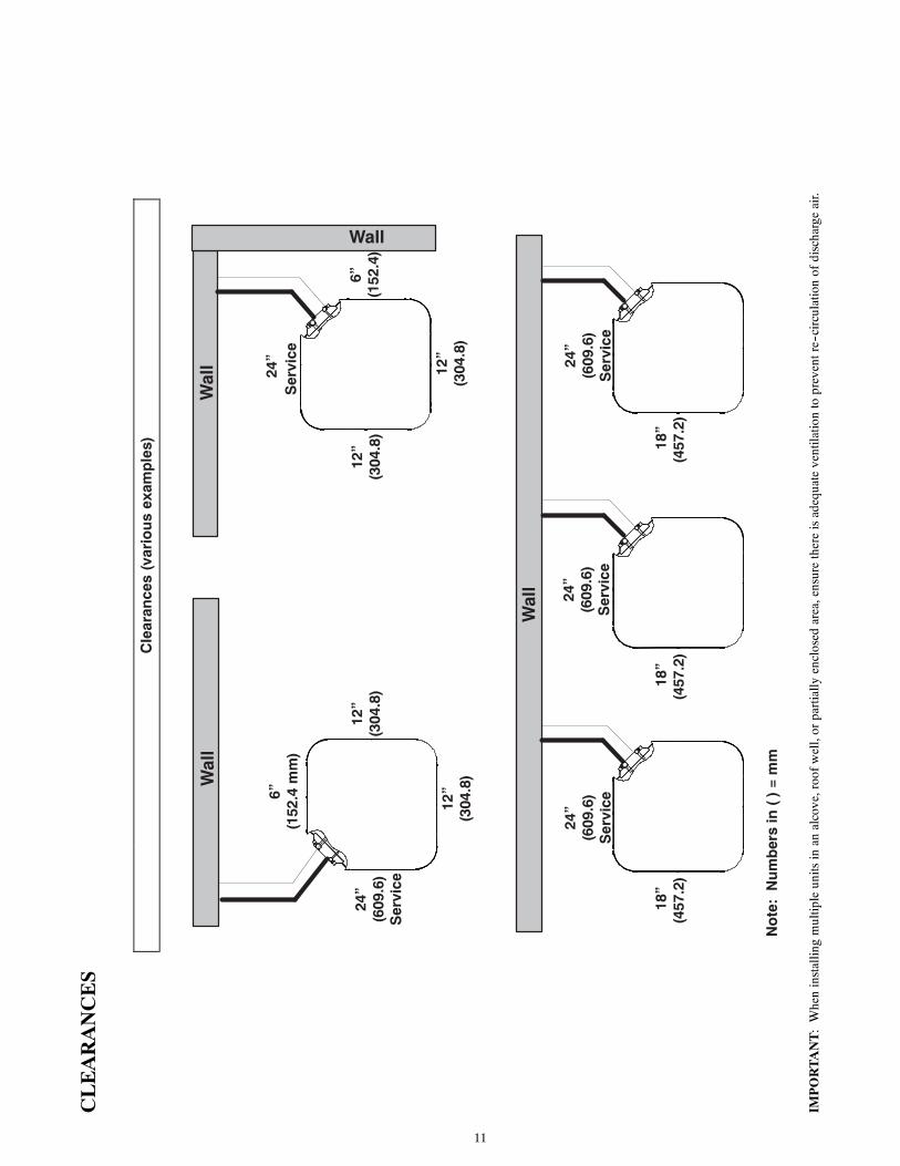
CLEARANCES
Cle
aran
ces
(var
iou
s ex
amp
les)
Wal
l
Wal
l
Wal
l
Wall
24”
Ser
vice
6”(1
52.4
mm
)
24”
(609
.6)
Ser
vice
24”
(609
.6)
Ser
vice
24”
(609
.6)
Ser
vice
24”
(609
.6)
Ser
vice
12”
(304
.8)
12”
(304
.8)
12”
(304
.8)
12”
(304
.8)
6”(1
52.4
)
No
te:
Nu
mb
ers
in (
) =
mm
18”
(457
.2)
18”
(457
.2)
18”
(457
.2)
IMPORTANT:Wheninstallingmultipleunitsinan
alcove,roofwell,orpartially
enclosed
area,ensurethereisadequateventilationtopreventre--circulationofdischargeair.
12
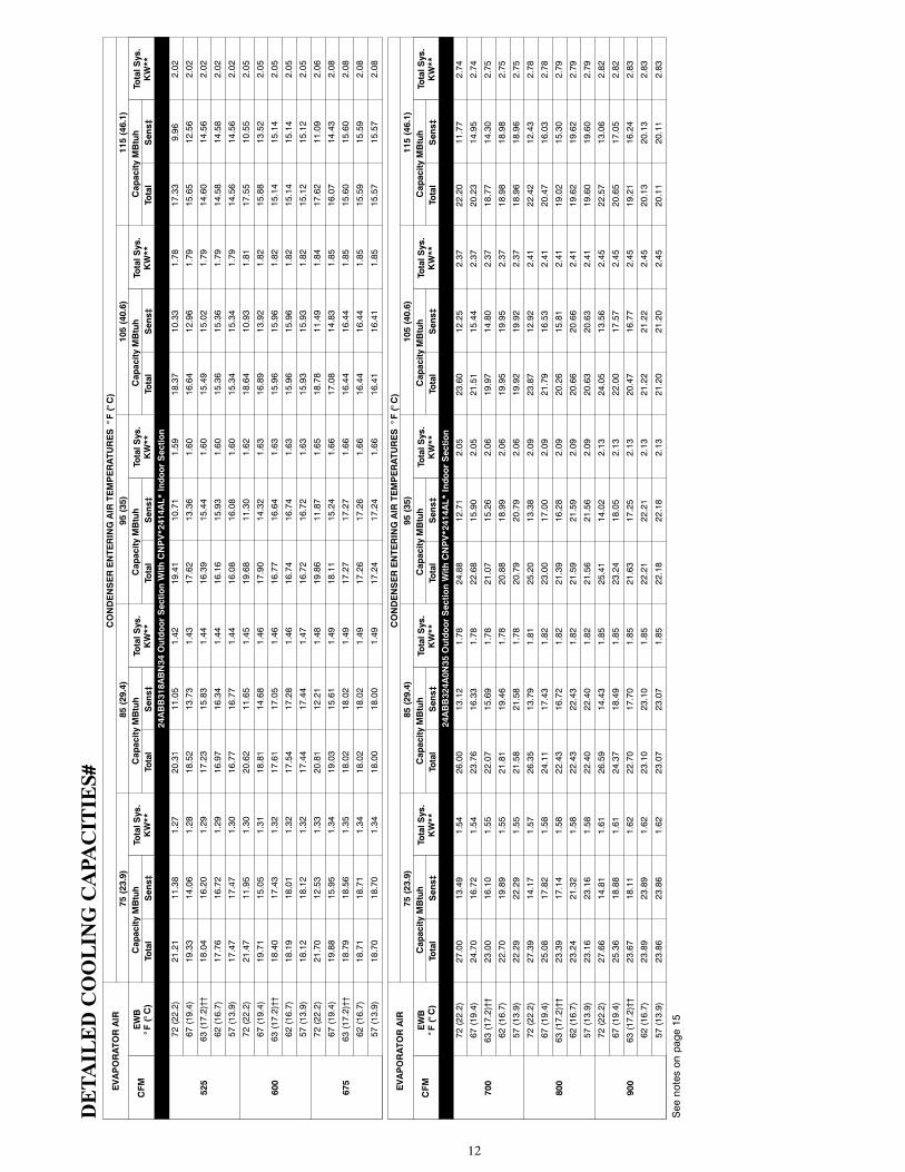
DETAILEDCOOLINGCAPA
CITIES#
EVAPORATORAIR
CONDENSERENTERINGAIRTEMPERATURES°F(°C)
75(23.9)
85(29.4)
95(35)
105(40.6)
115(46.1)
CFM
EWB
°F(°C)
CapacityMBtuh
TotalSys.
KW**
CapacityMBtuh
TotalSys.
KW**
CapacityMBtuh
TotalSys.
KW**
CapacityMBtuh
TotalSys.
KW**
CapacityMBtuh
TotalSys.
KW**
Total
Sens‡
Total
Sens‡
Total
Sens‡
Total
Sens‡
Total
Sens‡
24ABB318ABN34OutdoorSectionWithCNPV*2414AL*IndoorSection
525
72(22.2)
21.21
11.38
1.27
20.31
11.05
1.42
19.41
10.71
1.59
18.37
10.33
1.78
17.33
9.96
2.02
67(19.4)
19.33
14.06
1.28
18.52
13.73
1.43
17.62
13.36
1.60
16.64
12.96
1.79
15.65
12.56
2.02
63(17.2)††
18.04
16.20
1.29
17.23
15.83
1.44
16.39
15.44
1.60
15.49
15.02
1.79
14.60
14.56
2.02
62(16.7)
17.76
16.72
1.29
16.97
16.34
1.44
16.16
15.93
1.60
15.36
15.36
1.79
14.58
14.58
2.02
57(13.9)
17.47
17.47
1.30
16.77
16.77
1.44
16.08
16.08
1.60
15.34
15.34
1.79
14.56
14.56
2.02
600
72(22.2)
21.47
11.95
1.30
20.62
11.65
1.45
19.68
11.30
1.62
18.64
10.93
1.81
17.55
10.55
2.05
67(19.4)
19.71
15.05
1.31
18.81
14.68
1.46
17.90
14.32
1.63
16.89
13.92
1.82
15.88
13.52
2.05
63(17.2)††
18.40
17.43
1.32
17.61
17.05
1.46
16.77
16.64
1.63
15.96
15.96
1.82
15.14
15.14
2.05
62(16.7)
18.19
18.01
1.32
17.54
17.28
1.46
16.74
16.74
1.63
15.96
15.96
1.82
15.14
15.14
2.05
57(13.9)
18.12
18.12
1.32
17.44
17.44
1.47
16.72
16.72
1.63
15.93
15.93
1.82
15.12
15.12
2.05
675
72(22.2)
21.70
12.53
1.33
20.81
12.21
1.48
19.86
11.87
1.65
18.78
11.49
1.84
17.62
11.09
2.06
67(19.4)
19.88
15.95
1.34
19.03
15.61
1.49
18.11
15.24
1.66
17.08
14.83
1.85
16.07
14.43
2.08
63(17.2)††
18.79
18.56
1.35
18.02
18.02
1.49
17.27
17.27
1.66
16.44
16.44
1.85
15.60
15.60
2.08
62(16.7)
18.71
18.71
1.34
18.02
18.02
1.49
17.26
17.26
1.66
16.44
16.44
1.85
15.59
15.59
2.08
57(13.9)
18.70
18.70
1.34
18.00
18.00
1.49
17.24
17.24
1.66
16.41
16.41
1.85
15.57
15.57
2.08
EVAPORATORAIR
CONDENSERENTERINGAIRTEMPERATURES°F(°C)
75(23.9)
85(29.4)
95(35)
105(40.6)
115(46.1)
CFM
EWB
°F(°C)
CapacityMBtuh
TotalSys.
KW**
CapacityMBtuh
TotalSys.
KW**
CapacityMBtuh
TotalSys.
KW**
CapacityMBtuh
TotalSys.
KW**
CapacityMBtuh
TotalSys.
KW**
Total
Sens‡
Total
Sens‡
Total
Sens‡
Total
Sens‡
Total
Sens‡
24ABB324A0N35OutdoorSectionWithCNPV*2414AL*IndoorSection
700
72(22.2)
27.00
13.49
1.54
26.00
13.12
1.78
24.88
12.71
2.05
23.60
12.25
2.37
22.20
11.77
2.74
67(19.4)
24.70
16.72
1.54
23.76
16.33
1.78
22.68
15.90
2.05
21.51
15.44
2.37
20.23
14.95
2.74
63(17.2)††
23.00
16.10
1.55
22.07
15.69
1.78
21.07
15.26
2.06
19.97
14.80
2.37
18.77
14.30
2.75
62(16.7)
22.70
19.89
1.55
21.81
19.46
1.78
20.88
18.99
2.06
19.95
19.95
2.37
18.98
18.98
2.75
57(13.9)
22.29
22.29
1.55
21.58
21.58
1.78
20.79
20.79
2.06
19.92
19.92
2.37
18.96
18.96
2.75
800
72(22.2)
27.39
14.17
1.57
26.35
13.79
1.81
25.20
13.38
2.09
23.87
12.92
2.41
22.42
12.43
2.78
67(19.4)
25.08
17.82
1.58
24.11
17.43
1.82
23.00
17.00
2.09
21.79
16.53
2.41
20.47
16.03
2.78
63(17.2)††
23.39
17.14
1.58
22.43
16.72
1.82
21.39
16.28
2.09
20.26
15.81
2.41
19.02
15.30
2.79
62(16.7)
23.24
21.32
1.58
22.43
22.43
1.82
21.59
21.59
2.09
20.66
20.66
2.41
19.62
19.62
2.79
57(13.9)
23.16
23.16
1.58
22.40
22.40
1.82
21.56
21.56
2.09
20.63
20.63
2.41
19.60
19.60
2.79
900
72(22.2)
27.66
14.81
1.61
26.59
14.43
1.85
25.41
14.02
2.13
24.05
13.56
2.45
22.57
13.06
2.82
67(19.4)
25.36
18.88
1.61
24.37
18.49
1.85
23.24
18.05
2.13
22.00
17.57
2.45
20.65
17.05
2.82
63(17.2)††
23.67
18.11
1.62
22.70
17.70
1.85
21.63
17.25
2.13
20.47
16.77
2.45
19.21
16.24
2.83
62(16.7)
23.89
23.89
1.62
23.10
23.10
1.85
22.21
22.21
2.13
21.22
21.22
2.45
20.13
20.13
2.83
57(13.9)
23.86
23.86
1.62
23.07
23.07
1.85
22.18
22.18
2.13
21.20
21.20
2.45
20.11
20.11
2.83
Seenotesonpage15

13
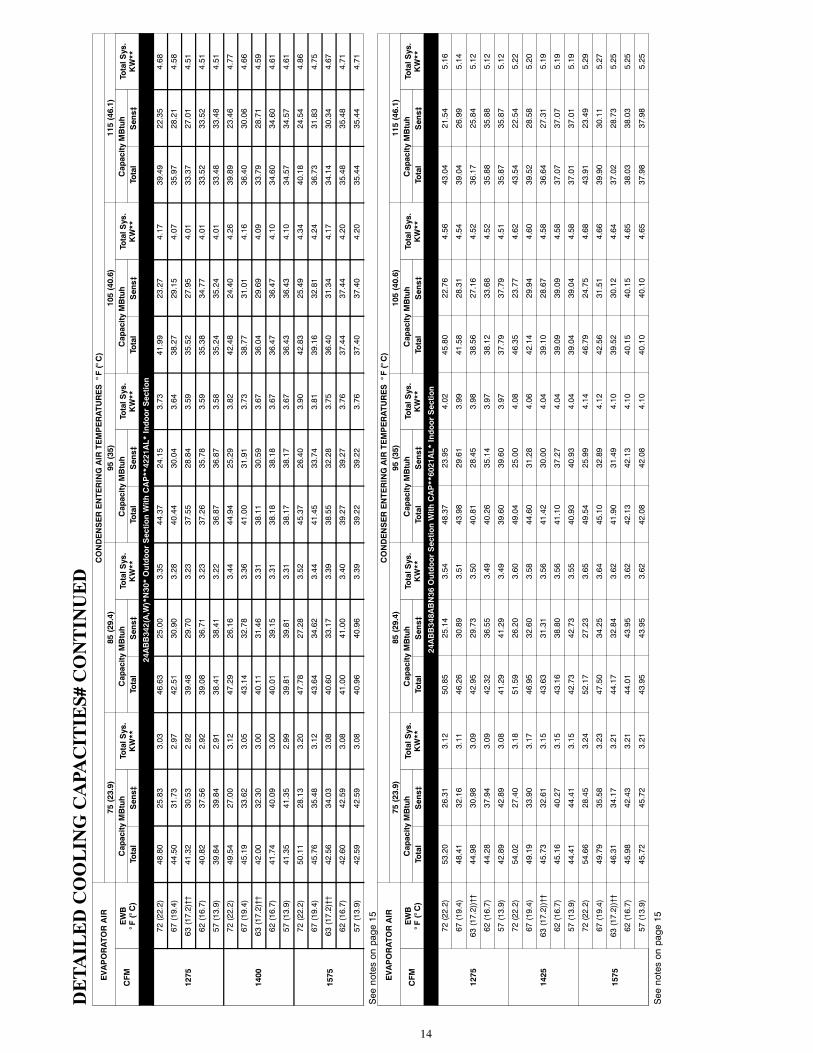
DETAILEDCOOLINGCAPA
CITIES#
CONTINUED
EVAPORATORAIR
CONDENSERENTERINGAIRTEMPERATURES°F(°C)
75(23.9)
85(29.4)
95(35)
105(40.6)
115(46.1)
CFM
EWB
°F(°C)
CapacityMBtuh
TotalSys.
KW**
CapacityMBtuh
TotalSys.
KW**
CapacityMBtuh
TotalSys.
KW**
CapacityMBtuh
TotalSys.
KW**
CapacityMBtuh
TotalSys.
KW**
Total
Sens‡
Total
Sens‡
Total
Sens‡
Total
Sens‡
Total
Sens‡
24ABB330ABN33OutdoorSectionWithCNPV*3117AL*IndoorSection
875
72(22.2)
33.22
16.91
2.06
31.69
16.39
2.26
30.06
15.84
2.50
28.48
15.31
2.77
27.41
14.95
3.12
67(19.4)
30.28
21.08
2.05
28.91
20.56
2.25
27.54
20.04
2.49
26.13
19.52
2.76
24.98
19.08
3.10
63(17.2)††
28.16
20.25
2.04
27.05
19.80
2.25
25.78
19.28
2.49
24.46
18.76
2.76
22.86
18.13
3.08
62(16.7)
28.07
25.27
2.05
26.80
26.56
2.25
25.71
25.71
2.48
24.60
24.60
2.76
23.29
23.29
3.08
57(13.9)
27.67
27.67
2.04
26.71
26.71
2.25
25.67
25.67
2.48
24.55
24.55
2.76
23.26
23.26
3.08
970
72(22.2)
33.81
17.69
2.10
32.00
17.08
2.30
30.30
16.51
2.53
28.71
15.99
2.81
27.49
15.59
3.14
67(19.4)
30.64
22.21
2.09
29.20
21.67
2.29
27.80
21.15
2.53
26.35
20.61
2.80
25.09
20.14
3.13
63(17.2)††
28.55
21.32
2.08
27.34
20.83
2.29
26.03
20.31
2.52
24.67
19.76
2.79
23.13
19.14
3.11
62(16.7)
28.67
28.67
2.09
27.47
27.47
2.29
26.36
26.36
2.52
25.20
25.20
2.80
24.14
24.14
3.14
57(13.9)
28.57
28.57
2.09
27.43
27.43
2.29
26.33
26.33
2.52
25.14
25.14
2.79
24.21
24.21
3.13
1125
72(22.2)
34.10
18.74
2.16
32.36
18.17
2.36
30.60
17.59
2.60
28.93
17.05
2.87
27.70
16.66
3.20
67(19.4)
31.10
23.99
2.15
29.57
23.42
2.36
28.11
22.88
2.59
26.63
22.32
2.86
25.46
21.89
3.21
63(17.2)††
29.25
23.06
2.15
27.68
22.44
2.35
26.34
21.90
2.59
24.91
21.33
2.86
23.65
20.80
3.19
62(16.7)
29.57
29.57
2.15
28.41
28.41
2.35
27.20
27.20
2.59
25.99
25.99
2.86
25.03
25.03
3.20
57(13.9)
29.57
29.57
2.15
28.38
28.38
2.35
27.20
27.20
2.59
25.95
25.95
2.86
24.99
24.99
3.20
EVAPORATORAIR
CONDENSERENTERINGAIRTEMPERATURES°F(°C)
75(23.9)
85(29.4)
95(35)
105(40.6)
115(46.1)
CFM
EWB
°F(°C)
CapacityMBtuh
TotalSys.
KW**
CapacityMBtuh
TotalSys.
KW**
CapacityMBtuh
TotalSys.
KW**
CapacityMBtuh
TotalSys.
KW**
CapacityMBtuh
TotalSys.
KW**
Total
Sens‡
Total
Sens‡
Total
Sens‡
Total
Sens‡
Total
Sens‡
24ABB336ABN35OutdoorSectionWithCAP**3721AL*IndoorSection
1050
72(22.2)
41.02
21.66
2.54
39.40
21.07
2.83
37.67
20.45
3.14
35.71
19.75
3.48
33.44
18.95
3.91
67(19.4)
37.34
26.81
2.53
35.82
26.20
2.81
34.20
25.55
3.11
32.39
24.83
3.45
30.24
23.98
3.87
63(17.2)††
34.68
25.78
2.53
33.23
25.15
2.81
31.71
24.49
3.10
29.97
23.75
3.44
27.94
22.89
3.85
62(16.7)
34.09
31.81
2.53
32.69
31.14
2.81
31.25
31.03
3.10
29.79
29.79
3.44
28.17
28.17
3.85
57(13.9)
33.44
33.44
2.53
32.31
32.31
2.81
31.10
31.10
3.10
29.74
29.74
3.43
28.12
28.12
3.85
1200
72(22.2)
41.67
22.87
2.60
40.00
22.28
2.90
38.19
21.64
3.21
36.16
20.93
3.56
33.84
20.12
3.98
67(19.4)
37.97
28.72
2.59
36.42
28.10
2.88
34.74
27.44
3.18
32.86
26.71
3.52
30.66
25.85
3.93
63(17.2)††
35.32
27.56
2.59
33.82
26.92
2.87
32.24
26.25
3.17
30.45
25.49
3.50
28.36
24.62
3.92
62(16.7)
35.04
34.70
2.59
33.72
33.72
2.87
32.44
32.44
3.16
30.99
30.99
3.50
29.26
29.26
3.92
57(13.9)
34.87
34.87
2.59
33.67
33.67
2.87
32.39
32.39
3.16
30.95
30.95
3.50
29.22
29.22
3.92
1350
72(22.2)
42.14
24.02
2.67
40.41
23.42
2.97
38.56
22.78
3.28
36.48
22.06
3.63
34.10
21.25
4.05
67(19.4)
38.45
30.58
2.65
36.85
29.95
2.94
35.14
29.28
3.24
33.22
28.53
3.58
30.99
27.65
4.00
63(17.2)††
35.80
29.28
2.65
34.26
28.63
2.93
32.63
27.95
3.23
30.83
27.19
3.57
28.68
26.27
3.98
62(16.7)
36.12
36.12
2.65
34.86
34.86
2.93
33.50
33.50
3.23
31.98
31.98
3.57
30.16
30.16
3.99
57(13.9)
36.07
36.07
2.65
34.81
34.81
2.93
33.45
33.45
3.23
31.94
31.94
3.57
30.12
30.12
3.99
14
DETAILEDCOOLINGCAPA
CITIES#
CONTINUED
EVAPORATORAIR
CONDENSERENTERINGAIRTEMPERATURES°F(°C)
75(23.9)
85(29.4)
95(35)
105(40.6)
115(46.1)
CFM
EWB
°F(°C)
CapacityMBtuh
TotalSys.
KW**
CapacityMBtuh
TotalSys.
KW**
CapacityMBtuh
TotalSys.
KW**
CapacityMBtuh
TotalSys.
KW**
CapacityMBtuh
TotalSys.
KW**
Total
Sens‡
Total
Sens‡
Total
Sens‡
Total
Sens‡
Total
Sens‡
24ABB342(A,W)*N30*OutdoorSectionWithCAP**4221AL*IndoorSection
1275
72(22.2)
48.80
25.83
3.03
46.63
25.00
3.35
44.37
24.15
3.73
41.99
23.27
4.17
39.49
22.35
4.68
67(19.4)
44.50
31.73
2.97
42.51
30.90
3.28
40.44
30.04
3.64
38.27
29.15
4.07
35.97
28.21
4.58
63(17.2)††
41.32
30.53
2.92
39.48
29.70
3.23
37.55
28.84
3.59
35.52
27.95
4.01
33.37
27.01
4.51
62(16.7)
40.82
37.56
2.92
39.08
36.71
3.23
37.26
35.78
3.59
35.38
34.77
4.01
33.52
33.52
4.51
57(13.9)
39.84
39.84
2.91
38.41
38.41
3.22
36.87
36.87
3.58
35.24
35.24
4.01
33.48
33.48
4.51
1400
72(22.2)
49.54
27.00
3.12
47.29
26.16
3.44
44.94
25.29
3.82
42.48
24.40
4.26
39.89
23.46
4.77
67(19.4)
45.19
33.62
3.05
43.14
32.78
3.36
41.00
31.91
3.73
38.77
31.01
4.16
36.40
30.06
4.66
63(17.2)††
42.00
32.30
3.00
40.11
31.46
3.31
38.11
30.59
3.67
36.04
29.69
4.09
33.79
28.71
4.59
62(16.7)
41.74
40.09
3.00
40.01
39.15
3.31
38.18
38.18
3.67
36.47
36.47
4.10
34.60
34.60
4.61
57(13.9)
41.35
41.35
2.99
39.81
39.81
3.31
38.17
38.17
3.67
36.43
36.43
4.10
34.57
34.57
4.61
1575
72(22.2)
50.11
28.13
3.20
47.78
27.28
3.52
45.37
26.40
3.90
42.83
25.49
4.34
40.18
24.54
4.86
67(19.4)
45.76
35.48
3.12
43.64
34.62
3.44
41.45
33.74
3.81
39.16
32.81
4.24
36.73
31.83
4.75
63(17.2)††
42.56
34.03
3.08
40.60
33.17
3.39
38.55
32.28
3.75
36.40
31.34
4.17
34.14
30.34
4.67
62(16.7)
42.60
42.59
3.08
41.00
41.00
3.40
39.27
39.27
3.76
37.44
37.44
4.20
35.48
35.48
4.71
57(13.9)
42.59
42.59
3.08
40.96
40.96
3.39
39.22
39.22
3.76
37.40
37.40
4.20
35.44
35.44
4.71
Seenotesonpage15
EVAPORATORAIR
CONDENSERENTERINGAIRTEMPERATURES°F(°C)
75(23.9)
85(29.4)
95(35)
105(40.6)
115(46.1)
CFM
EWB
°F(°C)
CapacityMBtuh
TotalSys.
KW**
CapacityMBtuh
TotalSys.
KW**
CapacityMBtuh
TotalSys.
KW**
CapacityMBtuh
TotalSys.
KW**
CapacityMBtuh
TotalSys.
KW**
Total
Sens‡
Total
Sens‡
Total
Sens‡
Total
Sens‡
Total
Sens‡
24ABB348ABN36OutdoorSectionWithCAP**6021AL*IndoorSection
1275
72(22.2)
53.20
26.31
3.12
50.85
25.14
3.54
48.37
23.95
4.02
45.80
22.76
4.56
43.04
21.54
5.16
67(19.4)
48.41
32.16
3.11
46.26
30.89
3.51
43.98
29.61
3.99
41.58
28.31
4.54
39.04
26.99
5.14
63(17.2))††
44.98
30.98
3.09
42.95
29.73
3.50
40.81
28.45
3.98
38.56
27.16
4.52
36.17
25.84
5.12
62(16.7)
44.28
37.94
3.09
42.32
36.55
3.49
40.26
35.14
3.97
38.12
33.68
4.52
35.88
35.88
5.12
57(13.9)
42.89
42.89
3.08
41.29
41.29
3.49
39.60
39.60
3.97
37.79
37.79
4.51
35.87
35.87
5.12
1425
72(22.2)
54.02
27.40
3.18
51.59
26.20
3.60
49.04
25.00
4.08
46.35
23.77
4.62
43.54
22.54
5.22
67(19.4)
49.19
33.90
3.17
46.95
32.60
3.58
44.60
31.28
4.06
42.14
29.94
4.60
39.52
28.58
5.20
63(17.2))††
45.73
32.61
3.15
43.63
31.31
3.56
41.42
30.00
4.04
39.10
28.67
4.58
36.64
27.31
5.19
62(16.7)
45.16
40.27
3.15
43.16
38.80
3.56
41.10
37.27
4.04
39.09
39.09
4.58
37.07
37.07
5.19
57(13.9)
44.41
44.41
3.15
42.73
42.73
3.55
40.93
40.93
4.04
39.04
39.04
4.58
37.01
37.01
5.19
1575
72(22.2)
54.66
28.45
3.24
52.17
27.23
3.65
49.54
25.99
4.14
46.79
24.75
4.68
43.91
23.49
5.29
67(19.4)
49.79
35.58
3.23
47.50
34.25
3.64
45.10
32.89
4.12
42.56
31.51
4.66
39.90
30.11
5.27
63(17.2))††
46.31
34.17
3.21
44.17
32.84
3.62
41.90
31.49
4.10
39.52
30.12
4.64
37.02
28.73
5.25
62(16.7)
45.98
42.43
3.21
44.01
43.95
3.62
42.13
42.13
4.10
40.15
40.15
4.65
38.03
38.03
5.25
57(13.9)
45.72
45.72
3.21
43.95
43.95
3.62
42.08
42.08
4.10
40.10
40.10
4.65
37.98
37.98
5.25
Seenotesonpage15
15
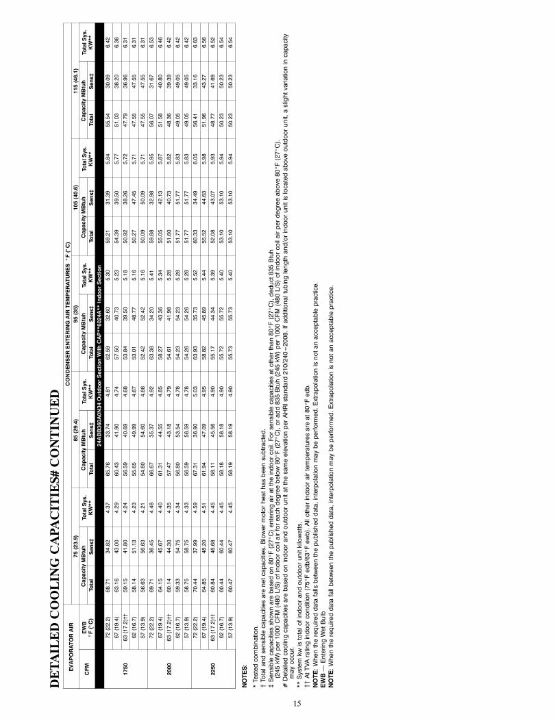
DETAILEDCOOLINGCAPA
CITIES#
CONTINUED
EVAPORATORAIR
CONDENSERENTERINGAIRTEMPERATURES°F(°C)
75(23.9)
85(29.4)
95(35)
105(40.6)
115(46.1)
CFM
EWB
°F(°C)
CapacityMBtuh
TotalSys.
KW**
CapacityMBtuh
TotalSys.
KW**
CapacityMBtuh
TotalSys.
KW**
CapacityMBtuh
TotalSys.
KW**
CapacityMBtuh
TotalSys.
KW**
Total
Sens‡
Total
Sens‡
Total
Sens‡
Total
Sens‡
Total
Sens‡
24ABB360A0N34OutdoorSectionWithCAP**6024A**IndoorSection
1750
72(22.2)
68.71
34.82
4.37
65.76
33.74
4.81
62.59
32.60
5.30
59.21
31.39
5.84
55.54
30.09
6.42
67(19.4)
63.16
43.00
4.29
60.43
41.90
4.74
57.50
40.73
5.23
54.39
39.50
5.77
51.03
38.20
6.36
63(17.2)††
59.15
41.80
4.24
56.59
40.69
4.68
53.84
39.50
5.18
50.92
38.26
5.72
47.79
36.96
6.31
62(16.7)
58.14
51.13
4.23
55.65
49.99
4.67
53.01
48.77
5.16
50.27
47.45
5.71
47.55
47.55
6.31
57(13.9)
56.63
56.63
4.21
54.60
54.60
4.66
52.42
52.42
5.16
50.09
50.09
5.71
47.55
47.55
6.31
2000
72(22.2)
69.71
36.45
4.48
66.67
35.37
4.92
63.38
34.20
5.41
59.88
32.98
5.95
56.07
31.67
6.53
67(19.4)
64.15
45.67
4.40
61.31
44.55
4.85
58.27
43.36
5.34
55.05
42.13
5.87
51.58
40.80
6.46
63(17.2)††
60.14
44.30
4.35
57.47
43.18
4.79
54.61
41.98
5.28
51.60
40.73
5.82
48.36
39.39
6.42
62(16.7)
59.33
54.75
4.34
56.80
53.54
4.78
54.23
54.23
5.28
51.77
51.77
5.83
49.05
49.05
6.42
57(13.9)
58.75
58.75
4.33
56.59
56.59
4.78
54.26
54.26
5.28
51.77
51.77
5.83
49.05
49.05
6.42
2250
72(22.2)
70.44
37.99
4.59
67.31
36.90
5.03
63.93
35.73
5.52
60.33
34.49
6.05
56.41
33.16
6.63
67(19.4)
64.85
48.20
4.51
61.94
47.09
4.95
58.82
45.89
5.44
55.52
44.63
5.98
51.96
43.27
6.56
63(17.2)††
60.84
46.68
4.45
58.11
45.56
4.90
55.17
44.34
5.39
52.08
43.07
5.93
48.77
41.69
6.52
62(16.7)
60.44
60.44
4.45
58.18
58.18
4.90
55.72
55.72
5.40
53.10
53.10
5.94
50.23
50.23
6.54
57(13.9)
60.47
60.47
4.45
58.19
58.19
4.90
55.73
55.73
5.40
53.10
53.10
5.94
50.23
50.23
6.54
NOTES:
*Testedcombination.
{Totalandsensiblecapacitiesarenetcapacities.Blowermotorheathasbeensubtracted.
}Sensiblecapacitiesshownarebasedon80_F(27_C)enteringairattheindoorcoil.Forsensiblecapacitiesatotherthan80_F(27_C),deduct835Btuh
(245kW)per1000CFM(480L/S)ofindoorcoilairforeachdegreebelow80_F(27_C),oradd835Btuh(245kW)per1000CFM(480L/S)ofindoorcoilairperdegreeabove80_F(27_C).
#DetailedcoolingcapacitiesarebasedonindoorandoutdoorunitatthesameelevationperAHRIstandard210/240---2008.Ifadditionaltubinglengthand/orindoorunitislocatedaboveoutdoorunit,aslightvariationincapacity
mayoccur.
**Systemkwistotalofindoorandoutdoorunitkilowatts.
{{AtTVAratingindoorcondition(75_Fedb/63_Fewb).Allotherindoorairtemperaturesareat80_Fedb.
NOTE:Whentherequireddatafallsbetweenthepublisheddata,interpolationmaybeperformed.Extrapolationisnotanacceptablepractice.
EWB—EnteringWetBulb
NOTE:Whentherequireddatafallbetweenthepublisheddata,interpolationmaybeperformed.Extrapolationisnotanacceptablepractice.
16
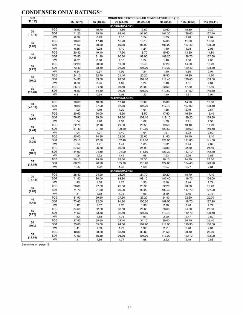
CONDENSER ONLY RATINGS*SST° F (° C)
CONDENSER ENTERING AIR TEMPERATURES ° F (° C)55 (12.78) 65 (18.33) 75 (23.89) 85 (29.44) 95 (35.0) 105 (40.56) 115 (46.11)
24ABB318ABN34
30(---1.11)
TCG 16.90 15.70 14.60 13.60 12.60 10.50 9.30SDT 71.20 79.70 88.40 97.90 107.30 126.60 137.10KW 0.88 0.99 1.10 1.24 1.39 1.78 2.04
35(1.67)
TCG 18.60 17.40 16.20 15.10 14.00 11.80 10.50SDT 71.50 80.80 89.50 98.90 108.20 127.40 138.00KW 0.86 0.98 1.10 1.24 1.40 1.78 2.06
40(4.44)
TCG 20.40 19.10 17.90 16.70 15.60 13.20 11.80SDT 73.50 81.90 90.60 99.90 109.20 128.70 137.60KW 0.87 0.98 1.10 1.24 1.40 1.80 2.03
45(7.22)
TCG 22.20 20.90 19.60 18.40 17.20 14.60 13.20SDT 73.40 83.10 91.70 101.00 110.30 129.40 138.50KW 0.84 0.97 1.09 1.24 1.40 1.80 2.04
50(10.0)
TCG 24.10 22.70 21.40 20.20 18.90 16.20 14.60SDT 74.30 83.50 92.80 102.10 111.40 130.40 139.50KW 0.83 0.95 1.09 1.24 1.40 1.81 2.04
55(12.78)
TCG 26.10 24.70 23.40 22.00 20.60 17.80 16.10SDT 75.50 84.80 94.00 103.30 112.50 131.50 140.30KW 0.81 0.94 1.08 1.23 1.40 1.81 2.04
24ABB324ABN35
30(---1.11)
TCG 18.60 18.00 17.40 16.60 15.80 14.90 13.80SDT 78.20 87.90 97.80 107.70 117.70 127.80 138.10KW 1.03 1.19 1.39 1.61 1.88 2.19 2.57
35(1.67)
TCG 20.60 20.00 19.30 18.50 17.60 16.60 15.40SDT 79.80 89.50 99.30 109.10 119.10 129.20 139.30KW 1.04 1.20 1.39 1.62 1.89 2.21 2.59
40(4.44)
TCG 22.70 22.10 21.30 20.50 19.50 18.40 17.20SDT 81.40 91.10 100.80 110.60 120.50 130.50 140.40KW 1.04 1.21 1.40 1.64 1.91 2.23 2.60
45(7.22)
TCG 25.00 24.30 23.50 22.60 21.60 20.40 19.10SDT 83.10 92.80 102.40 112.10 121.90 131.80 141.60KW 1.04 1.21 1.41 1.65 1.92 2.24 2.62
50(10.0)
TCG 27.50 26.70 25.80 24.90 23.80 22.50 21.10SDT 84.90 94.50 104.00 113.60 123.30 133.10 142.70KW 1.05 1.22 1.42 1.66 1.93 2.26 2.63
55(12.78)
TCG 30.10 29.30 28.30 27.30 26.10 24.80 23.30SDT 86.70 96.20 105.70 115.20 124.80 134.40 143.90KW 1.05 1.22 1.43 1.66 1.94 2.27 2.64
24ABB330ABN33
30(---1.11)
TCG 26.40 24.90 23.20 21.70 20.20 18.70 17.10SDT 71.50 80.00 88.80 98.10 107.40 116.70 126.00KW 1.43 1.58 1.75 1.95 2.18 2.44 2.74
35(1.67)
TCG 28.80 27.50 25.50 23.90 22.20 20.60 19.20SDT 71.70 81.30 89.90 99.20 108.40 117.70 127.20KW 1.41 1.58 1.75 1.96 2.19 2.45 2.76
40(4.44)
TCG 31.90 29.60 27.90 26.20 24.40 22.60 20.70SDT 73.40 82.00 91.20 100.30 109.50 118.70 127.90KW 1.42 1.57 1.76 1.96 2.20 2.46 2.77
45(7.22)
TCG 34.60 32.60 30.50 28.60 26.60 24.60 23.30SDT 74.50 83.50 92.50 101.60 110.70 119.70 129.40KW 1.42 1.58 1.76 1.97 2.20 2.47 2.80
50(10.0)
TCG 37.40 35.60 33.40 31.10 29.00 26.70 25.40SDT 75.80 85.00 94.00 102.90 111.90 120.90 130.50KW 1.41 1.59 1.77 1.97 2.21 2.48 2.81
55(12.78)
TCG 40.80 38.60 36.10 33.80 31.50 29.10 28.00SDT 77.50 86.50 95.30 104.30 113.20 122.10 132.00KW 1.41 1.59 1.77 1.98 2.22 2.49 2.83
See notes on page 18
17
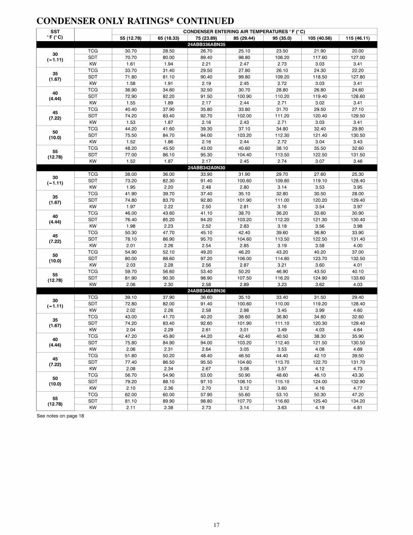
CONDENSER ONLY RATINGS* CONTINUEDSST° F (° C)
CONDENSER ENTERING AIR TEMPERATURES ° F (° C)55 (12.78) 65 (18.33) 75 (23.89) 85 (29.44) 95 (35.0) 105 (40.56) 115 (46.11)
24ABB336ABN35
30(---1.11)
TCG 30.70 28.50 26.70 25.10 23.50 21.90 20.00SDT 70.70 80.00 89.40 98.80 108.20 117.60 127.00KW 1.61 1.94 2.21 2.47 2.73 3.03 3.41
35(1.67)
TCG 33.70 31.40 29.50 27.80 26.10 24.30 22.20SDT 71.80 81.10 90.40 99.80 109.20 118.50 127.80KW 1.58 1.91 2.19 2.45 2.72 3.03 3.41
40(4.44)
TCG 36.90 34.60 32.50 30.70 28.80 26.80 24.60SDT 72.90 82.20 91.50 100.90 110.20 119.40 128.60KW 1.55 1.89 2.17 2.44 2.71 3.02 3.41
45(7.22)
TCG 40.40 37.90 35.80 33.80 31.70 29.50 27.10SDT 74.20 83.40 92.70 102.00 111.20 120.40 129.50KW 1.53 1.87 2.16 2.43 2.71 3.03 3.41
50(10.0)
TCG 44.20 41.60 39.30 37.10 34.80 32.40 29.80SDT 75.50 84.70 94.00 103.20 112.30 121.40 130.50KW 1.52 1.86 2.16 2.44 2.72 3.04 3.43
55(12.78)
TCG 48.20 45.50 43.00 40.60 38.10 35.50 32.60SDT 77.00 86.10 95.30 104.40 113.50 122.50 131.50KW 1.52 1.87 2.17 2.45 2.74 3.07 3.46
24ABB342A0N30
30(---1.11)
TCG 38.00 36.00 33.90 31.90 29.70 27.60 25.30SDT 73.20 82.30 91.40 100.60 109.80 119.10 128.40KW 1.95 2.20 2.48 2.80 3.14 3.53 3.95
35(1.67)
TCG 41.90 39.70 37.40 35.10 32.80 30.50 28.00SDT 74.80 83.70 92.80 101.90 111.00 120.20 129.40KW 1.97 2.22 2.50 2.81 3.16 3.54 3.97
40(4.44)
TCG 46.00 43.60 41.10 38.70 36.20 33.60 30.90SDT 76.40 85.20 94.20 103.20 112.20 121.30 130.40KW 1.98 2.23 2.52 2.83 3.18 3.56 3.98
45(7.22)
TCG 50.30 47.70 45.10 42.40 39.60 36.80 33.90SDT 78.10 86.90 95.70 104.60 113.50 122.50 131.40KW 2.01 2.26 2.54 2.85 3.19 3.58 4.00
50(10.0)
TCG 54.90 52.10 49.20 46.20 43.20 40.20 37.00SDT 80.00 88.60 97.20 106.00 114.80 123.70 132.50KW 2.03 2.28 2.56 2.87 3.21 3.60 4.01
55(12.78)
TCG 59.70 56.60 53.40 50.20 46.90 43.50 40.10SDT 81.90 90.30 98.90 107.50 116.20 124.90 133.60KW 2.06 2.30 2.58 2.89 3.23 3.62 4.03
24ABB348ABN36
30(---1.11)
TCG 39.10 37.90 36.60 35.10 33.40 31.50 29.40SDT 72.80 82.00 91.40 100.60 110.00 119.20 128.40KW 2.02 2.26 2.58 2.98 3.45 3.99 4.60
35(1.67)
TCG 43.00 41.70 40.20 38.60 36.80 34.80 32.60SDT 74.20 83.40 92.60 101.90 111.10 120.30 129.40KW 2.04 2.29 2.61 3.01 3.49 4.03 4.64
40(4.44)
TCG 47.20 45.80 44.20 42.40 40.50 38.30 35.90SDT 75.80 84.90 94.00 103.20 112.40 121.50 130.50KW 2.06 2.31 2.64 3.05 3.53 4.08 4.69
45(7.22)
TCG 51.80 50.20 48.40 46.50 44.40 42.10 39.50SDT 77.40 86.50 95.50 104.60 113.70 122.70 131.70KW 2.08 2.34 2.67 3.08 3.57 4.12 4.73
50(10.0)
TCG 56.70 54.90 53.00 50.90 48.60 46.10 43.30SDT 79.20 88.10 97.10 106.10 115.10 124.00 132.90KW 2.10 2.36 2.70 3.12 3.60 4.16 4.77
55(12.78)
TCG 62.00 60.00 57.90 55.60 53.10 50.30 47.20SDT 81.10 89.90 98.80 107.70 116.60 125.40 134.20KW 2.11 2.38 2.73 3.14 3.63 4.19 4.81
See notes on page 18
18
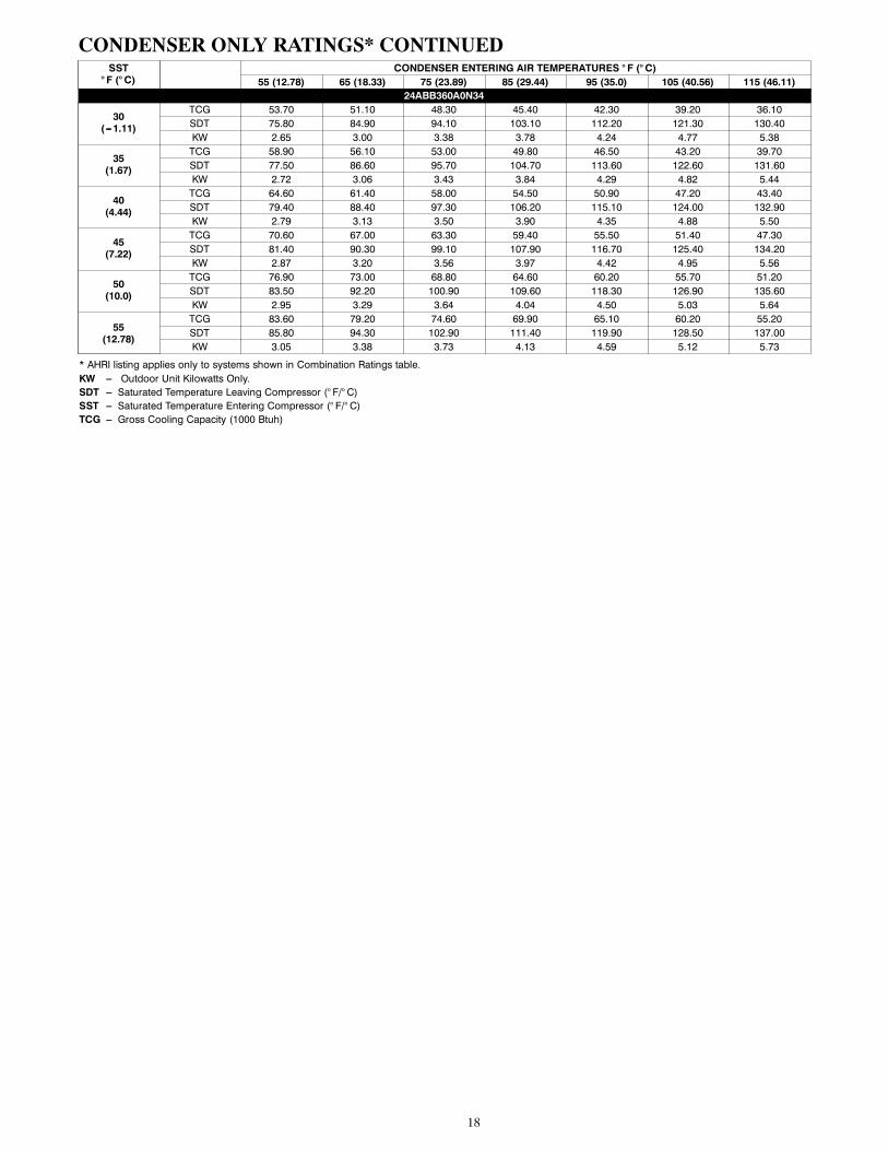
CONDENSER ONLY RATINGS* CONTINUEDSST° F (° C)
CONDENSER ENTERING AIR TEMPERATURES ° F (° C)55 (12.78) 65 (18.33) 75 (23.89) 85 (29.44) 95 (35.0) 105 (40.56) 115 (46.11)
24ABB360A0N34
30(---1.11)
TCG 53.70 51.10 48.30 45.40 42.30 39.20 36.10SDT 75.80 84.90 94.10 103.10 112.20 121.30 130.40KW 2.65 3.00 3.38 3.78 4.24 4.77 5.38
35(1.67)
TCG 58.90 56.10 53.00 49.80 46.50 43.20 39.70SDT 77.50 86.60 95.70 104.70 113.60 122.60 131.60KW 2.72 3.06 3.43 3.84 4.29 4.82 5.44
40(4.44)
TCG 64.60 61.40 58.00 54.50 50.90 47.20 43.40SDT 79.40 88.40 97.30 106.20 115.10 124.00 132.90KW 2.79 3.13 3.50 3.90 4.35 4.88 5.50
45(7.22)
TCG 70.60 67.00 63.30 59.40 55.50 51.40 47.30SDT 81.40 90.30 99.10 107.90 116.70 125.40 134.20KW 2.87 3.20 3.56 3.97 4.42 4.95 5.56
50(10.0)
TCG 76.90 73.00 68.80 64.60 60.20 55.70 51.20SDT 83.50 92.20 100.90 109.60 118.30 126.90 135.60KW 2.95 3.29 3.64 4.04 4.50 5.03 5.64
55(12.78)
TCG 83.60 79.20 74.60 69.90 65.10 60.20 55.20SDT 85.80 94.30 102.90 111.40 119.90 128.50 137.00KW 3.05 3.38 3.73 4.13 4.59 5.12 5.73
* AHRI listing applies only to systems shown in Combination Ratings table.KW --- Outdoor Unit Kilowatts Only.SDT --- Saturated Temperature Leaving Compressor (° F/° C)SST --- Saturated Temperature Entering Compressor (° F/° C)TCG --- Gross Cooling Capacity (1000 Btuh)
19
GUIDE SPECIFICATIONSGENERALSystem DescriptionOutdoor--mounted, air--cooled, split--system air conditioner unitsuitable for ground or rooftop installation. Unit consists of ahermetic compressor, an air--cooled coil, propeller--typecondenser fan, and a control box. Unit will discharge supply airupward as shown on contract drawings. Unit will be used in arefrigeration circuit to match up to a packaged fan coil or coilunit.
Quality Assurance— Unit will be rated in accordance with the latest edition
of AHRI Standard 210.
— Unit will be certified for capacity and efficiency, andlisted in the latest AHRI directory.
— Unit construction will comply with latest edition ofANSI/ ASHRAE and with NEC.
— Unit will be constructed in accordance with ULstandards and will carry the UL label of approval. Unitwill have c--UL--us approval.
— Unit cabinet will be capable of withstanding FederalTest Method Standard No. 141 (Method 6061) 500--hrsalt spray test.
— Air--cooled condenser coils will be leak tested at 150psig and pressure tested at 450 psig.
— Unit constructed in ISO9001 approved facility.
Delivery, Storage, and Handling— Unit will be shipped as single package only and is
stored and handled per unit manufacturer’srecommendations.
Warranty (for inclusion by specifying engineer)— U.S. and Canada only.
PRODUCTSEquipmentFactory assembled, single piece, air--cooled air conditioner unit.Contained within the unit enclosure is all factory wiring, piping,controls, compressor, refrigerant charge Puronr (R--410A), andspecial features required prior to field start--up.
Unit Cabinet
— Unit cabinet will be constructed of galvanized steel,bonderized, and coated with a powder coat paint.
— All models have dense grille.
Fans
— Condenser fan will be direct--drive propeller type,discharging air upward.
— Condenser fan motors will be totally enclosed, 1--phasetype with class B insulation and permanently lubricatedbearings. Shafts will be corrosion resistant.
— Fan blades will be statically and dynamically balanced.
— Condenser fan openings will be equipped with coatedsteel wire safety guards.
Compressor
— Compressor will be hermetically sealed.
— Compressor will be mounted on rubber vibrationisolators.
AIR--COOLED, SPLIT--SYSTEM AIR CONDITIONER24ABB3
1--1/2 TO 5 NOMINAL TONSCondenser Coil
— Condenser coil will be air cooled.
— Coil will be constructed of aluminum fins mechanicallybonded to copper tubes which are then cleaned,dehydrated, and sealed.
Refrigeration Components
— Refrigeration circuit components will includeliquid--line shutoff valve with sweat connections,vapor--line shutoff valve with sweat connections,system charge of Puronr (R--410A) refrigerant, andcompressor oil.
— Unit will be equipped with filter drier for Puronrefrigerant.
Operating Characteristics— The capacity of the unit will meet or exceed _____
Btuh at a suction temperature of _____ _F/_C. Thepower consumption at full load will not exceed _____kW.
— Combination of the unit and the evaporator or fan coilunit will have a total net cooling capacity of _____Btuh or greater at conditions of _____ CFM enteringair temperature at the evaporator at _____ _F/_C wetbulb and _____ _F/_C dry bulb, and air entering theunit at _____ _F/_C.
— The system will have a SEER of _____ Btuh/watt orgreater at DOE conditions.
Electrical Requirements— Nominal unit electrical characteristics will be _____ v,
single phase, 60 hz. The unit will be capable ofsatisfactory operation within voltage limits of _____ vto _____ v.
— Nominal unit electrical characteristics will be _____ v,three phase, 60 hz. The unit will be capable ofsatisfactory operation within voltage limits of _____ vto _____ v.
— Unit electrical power will be single point connection.
— Control circuit will be 24v.
Special Features— Refer to section of this literature identifying accessories
and descriptions for specific features and availableenhancements.
20
SYSTEM DESIGN SUMMARY1. Intended for outdoor installation with free air inlet and outlet. Outdoor fan external static pressure available is less than 0.01--in. wc.
2. Minimum outdoor operating air temperature without low--ambient operation accessory is 55_F (12.8_C).
3. Maximum outdoor operating air temperature is 115_F (46.1_C).
4. For reliable operation, unit should be level in all horizontal planes.
5. For interconnecting refrigerant tube lengths greater than 80 ft (23.4 m) and/or 35 ft (10.7 m) vertical differential, consult ResidentialPiping and Longline Guideline and Service Manual available from equipment distributor.
6. If any refrigerant tubing is buried, provide a 6 in. (152.4 mm) vertical rise to the valve connections at the unit. Refrigerant tubinglengths up to 36 in. (914.4 mm) may be buried without further consideration. Do not bury refrigerant lines longer than 36 in. (914.4mm).
7. Use only copper wire for electric connection at unit. Aluminum and clad aluminum are not acceptable for the type of connectorprovided.
8. Do not apply capillary tube indoor coils to these units.
9. Factory--supplied filter drier must be installed.
Copyright 2019 Carrier Corp. S 7310 W. Morris St. S Indianapolis, IN 46231
Manufacturer reserves the right to change, at any time, specifications and designs without notice and without obligations.
Catalog No: 24ABB3---18PD
Replaces: 24ABB3---17PD
Edition Date: 05/19