Embed Size (px)
Citation preview
Product Data
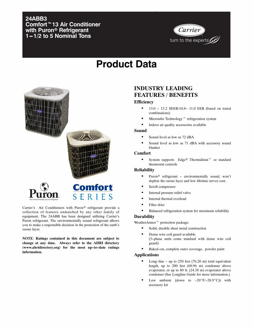
24ABB3Comfortt13 Air Conditionerwith Puronr Refrigerant1---1/2 to 5 Nominal Tons
the environmentally sound refrigerant
Carrier’s Air Conditioners with Puronr refrigerant provide acollection of features unmatched by any other family ofequipment. The 24ABB has been designed utilizing Carrier’sPuron refrigerant. The environmentally sound refrigerant allowsyou to make a responsible decision in the protection of the earth’sozone layer.
NOTE: Ratings contained in this document are subject tochange at any time. Always refer to the AHRI directory(www.ahridirectory.org) for the most up--to--date ratingsinformation.
INDUSTRY LEADINGFEATURES / BENEFITSEfficiency
S 13.0 -- 13.2 SEER/10.8-- 11.0 EER (based on testedcombinations)
S Microtube Technologyt refrigeration system
S Indoor air quality accessories available
SoundS Sound level as low as 72 dBA
S Sound level as low as 71 dBA with accessory soundblanket
ComfortS System supports Edger Thermidistatt or standard
thermostat controls
ReliabilityS Puronr refrigerant -- environmentally sound, won’t
deplete the ozone layer and low lifetime servce cost.
S Scroll compressor
S Internal pressure relief valve
S Internal thermal overload
S Filter drier
S Balanced refrigeration system for maximum reliability
DurabilityWeatherArmort protection package:
S Solid, durable sheet metal construction
S Dense wire coil guard available(3--phase units come standard with dense wire coilguard)
S Baked--on, complete outer coverage, powder paint
ApplicationsS Long--line -- up to 250 feet (76.20 m) total equivalent
length, up to 200 feet (60.96 m) condenser aboveevaporator, or up to 80 ft. (24.38 m) evaporator abovecondenser (See Longline Guide for more information.)
S Low ambient (down to --20_F/--28.9_C)) withaccessory kit
2
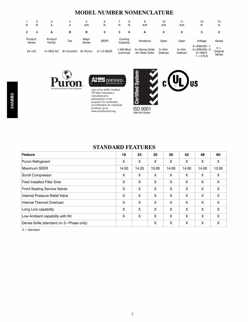
MODEL NUMBER NOMENCLATURE1 2 3 4 5 6 7 8 9 10 11 12 13N N A A A/N N N N A/N A/N A/N N N
2 4 A B B 3 3 6 A 0 0 3 0
ProductSeries
ProductFamily Tier Major
Series SEER CoolingCapacity Variations Open Open Voltage Series
24=AC A=RES AC B=Comfort B=Puron 3=13 SEER 1.000 Btuh(nominal)
A=Dense GrilleW=Wide Grille
0=NotDefined
0=NotDefined
3=208/230---15=208/230---36=460/31 = 575/3
0 =OriginalSeries
the environmentally sound refrigerant Use of the AHRI CertifiedTM Mark indicates amanufacturer’s participation in the program For verification of certification for individual products, go to www.ahridirectory.org.
STANDARD FEATURESFeature 18 24 30 36 42 48 60
Puron Refrigerant X X X X X X X
Maximum SEER 14.50 14.25 15.00 14.00 14.00 14.00 13.50
Scroll Compressor X X X X X X X
Field Installed Filter Drier X X X X X X X
Front Seating Service Valves X X X X X X X
Internal Pressure Relief Valve X X X X X X X
Internal Thermal Overload X X X X X X X
Long Line capability X X X X X X X
Low Ambient capability with Kit X X X X X X X
Dense Grille (standard on 3---Phase only) X X X X X
X = Standard
24ABB3
3
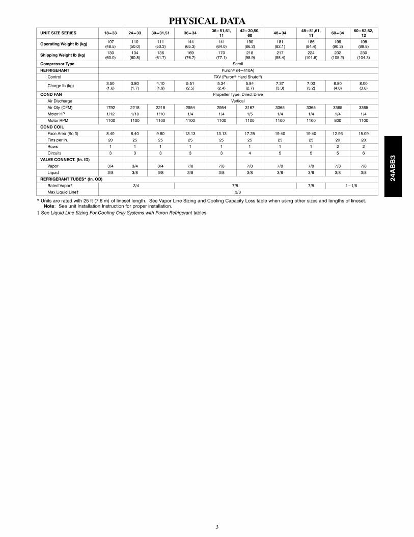
PHYSICAL DATAUNIT SIZE SERIES 18---33 24---33 30---31,51 36---34 36---51,61,
1142---30,50,60 48---34 48---51,61,
11 60---34 60---52,62,12
Operating Weight lb (kg) 107(48.5)
110(50.0)
111(50.3)
144(65.3)
141(64.0)
190(86.2)
181(82.1)
186(84.4)
199(90.3)
198(89.8)
Shipping Weight lb (kg) 130(60.0)
134(60.8)
136(61.7)
169(76.7)
170(77.1)
218(98.9)
217(98.4)
224(101.6)
232(105.2)
230(104.3)
Compressor Type Scroll
REFRIGERANT Puron (R---410A)
Control TXV (Puron Hard Shutoff)
Charge lb (kg) 3.50(1.6)
3.80(1.7)
4.10(1.9)
5.51(2.5)
5.34(2.4)
5.84(2.7)
7.37(3.3)
7.00(3.2)
8.80(4.0)
8.00(3.6)
COND FAN Propeller Type, Direct Drive
Air Discharge Vertical
Air Qty (CFM) 1792 2218 2218 2954 2954 3167 3365 3365 3365 3365
Motor HP 1/12 1/10 1/10 1/4 1/4 1/5 1/4 1/4 1/4 1/4
Motor RPM 1100 1100 1100 1100 1100 1100 1100 1100 800 1100
COND COILFace Area (Sq ft) 8.40 8.40 9.80 13.13 13.13 17.25 19.40 19.40 12.93 15.09
Fins per In. 20 25 25 25 25 25 25 25 20 20
Rows 1 1 1 1 1 1 1 1 2 2
Circuits 3 3 3 3 3 4 5 5 5 6
VALVE CONNECT. (In. ID)Vapor 3/4 3/4 3/4 7/8 7/8 7/8 7/8 7/8 7/8 7/8
Liquid 3/8 3/8 3/8 3/8 3/8 3/8 3/8 3/8 3/8 3/8
REFRIGERANT TUBES* (In. OD)Rated Vapor* 3/4 7/8 7/8 1---1/8
Max Liquid Line{ 3/8
* Units are rated with 25 ft (7.6 m) of lineset length. See Vapor Line Sizing and Cooling Capacity Loss table when using other sizes and lengths of lineset.Note: See unit Installation Instruction for proper installation.
{ See Liquid Line Sizing For Cooling Only Systems with Puron Refrigerant tables.
24ABB3
4
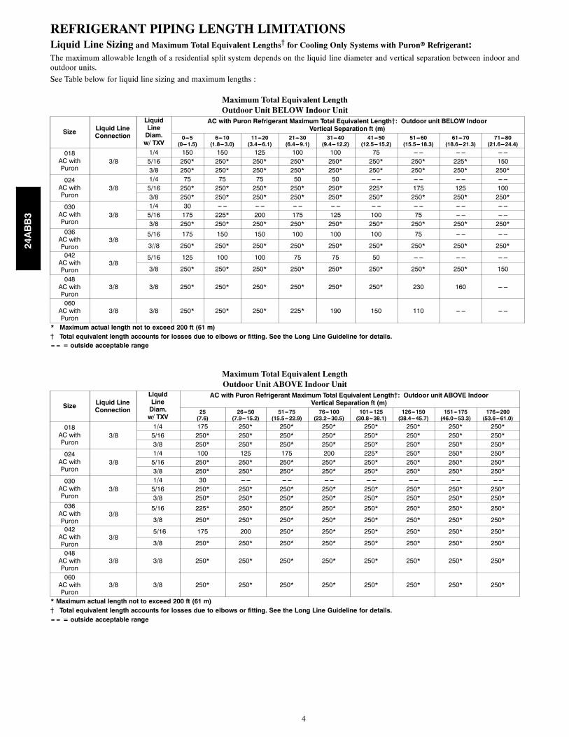
REFRIGERANT PIPING LENGTH LIMITATIONSLiquid Line Sizing and Maximum Total Equivalent Lengths{ for Cooling Only Systems with Puronr Refrigerant:The maximum allowable length of a residential split system depends on the liquid line diameter and vertical separation between indoor andoutdoor units.
See Table below for liquid line sizing and maximum lengths :
Maximum Total Equivalent LengthOutdoor Unit BELOW Indoor Unit
Size Liquid LineConnection
LiquidLineDiam.w/ TXV
AC with Puron Refrigerant Maximum Total Equivalent Length{: Outdoor unit BELOW IndoorVertical Separation ft (m)
0---5(0---1.5)
6---10(1.8---3.0)
11---20(3.4---6.1)
21---30(6.4---9.1)
31---40(9.4---12.2)
41---50(12.5---15.2)
51---60(15.5---18.3)
61---70(18.6---21.3)
71---80(21.6---24.4)
018AC withPuron
3/81/4 150 150 125 100 100 75 --- --- --- --- --- ---5/16 250* 250* 250* 250* 250* 250* 250* 225* 1503/8 250* 250* 250* 250* 250* 250* 250* 250* 250*
024AC withPuron
3/81/4 75 75 75 50 50 --- --- --- --- --- --- --- ---5/16 250* 250* 250* 250* 250* 225* 175 125 1003/8 250* 250* 250* 250* 250* 250* 250* 250* 250*
030AC withPuron
3/81/4 30 --- --- --- --- --- --- --- --- --- --- --- --- --- --- --- ---5/16 175 225* 200 175 125 100 75 --- --- --- ---3/8 250* 250* 250* 250* 250* 250* 250* 250* 250*
036AC withPuron
3/85/16 175 150 150 100 100 100 75 --- --- --- ---
3//8 250* 250* 250* 250* 250* 250* 250* 250* 250*042AC withPuron
3/85/16 125 100 100 75 75 50 --- --- --- --- --- ---
3/8 250* 250* 250* 250* 250* 250* 250* 250* 150
048AC withPuron
3/8 3/8 250* 250* 250* 250* 250* 250* 230 160 --- ---
060AC withPuron
3/8 3/8 250* 250* 250* 225* 190 150 110 --- --- --- ---
* Maximum actual length not to exceed 200 ft (61 m){ Total equivalent length accounts for losses due to elbows or fitting. See the Long Line Guideline for details.--- --- = outside acceptable range
Maximum Total Equivalent LengthOutdoor Unit ABOVE Indoor Unit
Size Liquid LineConnection
LiquidLineDiam.w/ TXV
AC with Puron Refrigerant Maximum Total Equivalent Length{: Outdoor unit ABOVE IndoorVertical Separation ft (m)
25(7.6)
26---50(7.9---15.2)
51---75(15.5---22.9)
76---100(23.2---30.5)
101---125(30.8---38.1)
126---150(38.4---45.7)
151---175(46.0---53.3)
176---200(53.6---61.0)
018AC withPuron
3/81/4 175 250* 250* 250* 250* 250* 250* 250*5/16 250* 250* 250* 250* 250* 250* 250* 250*3/8 250* 250* 250* 250* 250* 250* 250* 250*
024AC withPuron
3/81/4 100 125 175 200 225* 250* 250* 250*5/16 250* 250* 250* 250* 250* 250* 250* 250*3/8 250* 250* 250* 250* 250* 250* 250* 250*
030AC withPuron
3/81/4 30 --- --- --- --- --- --- --- --- --- --- --- --- --- ---5/16 250* 250* 250* 250* 250* 250* 250* 250*3/8 250* 250* 250* 250* 250* 250* 250* 250*
036AC withPuron
3/85/16 225* 250* 250* 250* 250* 250* 250* 250*
3/8 250* 250* 250* 250* 250* 250* 250* 250*042AC withPuron
3/85/16 175 200 250* 250* 250* 250* 250* 250*
3/8 250* 250* 250* 250* 250* 250* 250* 250*048AC withPuron
3/8 3/8 250* 250* 250* 250* 250* 250* 250* 250*
060AC withPuron
3/8 3/8 250* 250* 250* 250* 250* 250* 250* 250*
* Maximum actual length not to exceed 200 ft (61 m){ Total equivalent length accounts for losses due to elbows or fitting. See the Long Line Guideline for details.--- --- = outside acceptable range
24ABB3
5
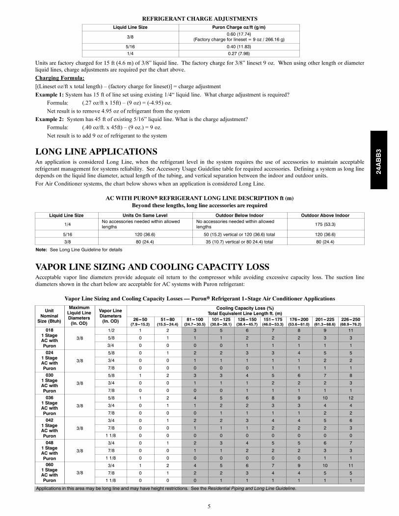
REFRIGERANT CHARGE ADJUSTMENTSLiquid Line Size Puron Charge oz/ft (g/m)
3/8 0.60 (17.74)(Factory charge for lineset = 9 oz / 266.16 g)
5/16 0.40 (11.83)1/4 0.27 (7.98)
Units are factory charged for 15 ft (4.6 m) of 3/8” liquid line. The factory charge for 3/8” lineset 9 oz. When using other length or diameterliquid lines, charge adjustments are required per the chart above.
Charging Formula:
[(Lineset oz/ft x total length) – (factory charge for lineset)] = charge adjustment
Example 1: System has 15 ft of line set using existing 1/4“ liquid line. What charge adjustment is required?
Formula: (.27 oz/ft x 15ft) – (9 oz) = (-4.95) oz.
Net result is to remove 4.95 oz of refrigerant from the system
Example 2: System has 45 ft of existing 5/16” liquid line. What is the charge adjustment?
Formula: (.40 oz/ft. x 45ft) – (9 oz.) = 9 oz.
Net result is to add 9 oz of refrigerant to the system
LONG LINE APPLICATIONSAn application is considered Long Line, when the refrigerant level in the system requires the use of accessories to maintain acceptablerefrigerant management for systems reliability. See Accessory Usage Guideline table for required accessories. Defining a system as long linedepends on the liquid line diameter, actual length of the tubing, and vertical separation between the indoor and outdoor units.
For Air Conditioner systems, the chart below shows when an application is considered Long Line.
AC WITH PURONr REFRIGERANT LONG LINE DESCRIPTION ft (m)Beyond these lengths, long line accessories are required
Liquid Line Size Units On Same Level Outdoor Below Indoor Outdoor Above Indoor
1/4 No accessories needed within allowedlengths
No accessories needed within allowedlengths 175 (53.3)
5/16 120 (36.6) 50 (15.2) vertical or 120 (36.6) total 120 (36.6)
3/8 80 (24.4) 35 (10.7) vertical or 80 24.4) total 80 (24.4)
Note: See Long Line Guideline for details
VAPOR LINE SIZING AND COOLING CAPACITY LOSSAcceptable vapor line diameters provide adequate oil return to the compressor while avoiding excessive capacity loss. The suction linediameters shown in the chart below are acceptable for AC systems with Puron refrigerant:
Vapor Line Sizing and Cooling Capacity Losses — Puronr Refrigerant 1--Stage Air Conditioner Applications
UnitNominalSize (Btuh)
MaximumLiquid LineDiameters(In. OD)
Vapor LineDiameters(In. OD)
Cooling Capacity Loss (%)Total Equivalent Line Length ft. (m)
26---50(7.9---15.2)
51---80(15.5---24.4)
81---100(24.7---30.5)
101---125(30.8---38.1)
126---150(38.4---45.7)
151---175(46.0---53.3)
176---200(53.6---61.0)
201---225(61.3---68.6)
226---250(68.9---76.2)
0181 StageAC withPuron
3/8
1/2 1 2 3 5 6 7 8 9 11
5/8 0 1 1 1 2 2 2 3 3
3/4 0 0 0 0 1 1 1 1 1
0241 StageAC withPuron
3/8
5/8 0 1 2 2 3 3 4 5 5
3/4 0 0 1 1 1 1 1 2 2
7/8 0 0 0 0 0 1 1 1 1
0301 StageAC withPuron
3/8
5/8 1 2 3 3 4 5 6 7 8
3/4 0 0 1 1 1 2 2 2 3
7/8 0 0 0 0 1 1 1 1 1
0361 StageAC withPuron
3/8
5/8 1 2 4 5 6 8 9 10 12
3/4 0 1 1 2 2 3 3 4 4
7/8 0 0 0 1 1 1 1 2 2
0421 StageAC withPuron
3/8
3/4 0 1 2 2 3 4 4 5 6
7/8 0 0 1 1 1 2 2 2 3
1 1/8 0 0 0 0 0 0 0 0 0
0481 StageAC withPuron
3/8
3/4 0 1 2 3 4 5 5 6 7
7/8 0 0 1 1 2 2 2 3 3
1 1/8 0 0 0 0 0 0 0 1 10601 StageAC withPuron
3/8
3/4 1 2 4 5 6 7 9 10 11
7/8 0 1 2 2 3 4 4 5 5
1 1/8 0 0 0 1 1 1 1 1 1
Applications in this area may be long line and may have height restrictions. See the Residential Piping and Long Line Guideline.
24ABB3
6
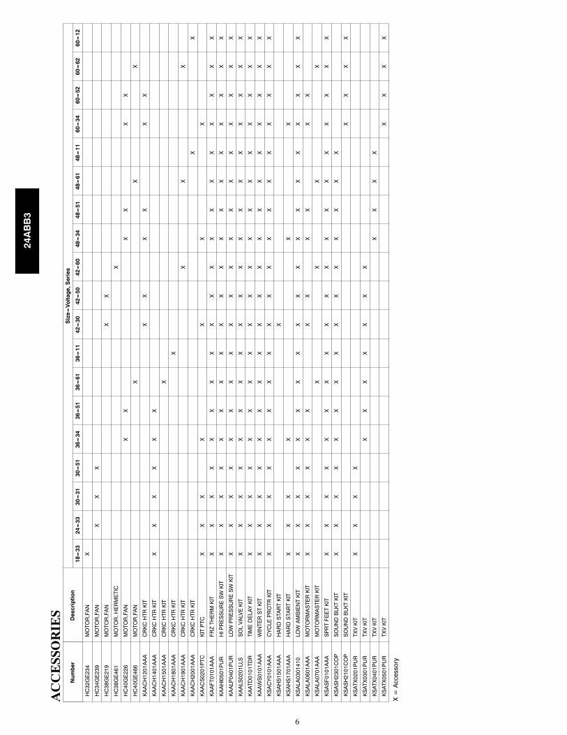
AC
CE
SSO
RIE
SNumber
Description
Size---Voltage,Series
18---33
24---33
30---31
30---51
36---34
36---51
36---61
36---11
42---30
42---50
42---60
48---34
48---51
48---61
48---11
60---34
60---52
60---62
60---12
HC32GE234
MOTOR,FAN
X
HC34GE239
MOTOR,FAN
XX
X
HC38GE219
MOTOR,FAN
XX
HC38GE461
MOTOR,HERMETIC
X
HC40GE226
MOTOR,FAN
XX
XX
XX
HC40GE466
MOTOR,FAN
XX
X
KAACH1201AAA
CRKCHTRKIT
XX
XX
XX
KAACH1401AAA
CRKCHTRKIT
XX
XX
XX
KAACH1501AAA
CRKCHTRKIT
X
KAACH1801AAA
CRKCHTRKIT
X
KAACH1901AAA
CRKCHTRKIT
XX
X
KAACH2001AAA
CRKCHTRKIT
XX
KAACS0201PTC
KITPTC
XX
XX
XX
X
KAAFT0101AAA
FRZTHERMKIT
XX
XX
XX
XX
XX
XX
XX
XX
XX
X
KAAHI0501PUR
HIPRESSURESWKIT
XX
XX
XX
XX
XX
XX
XX
XX
XX
X
KAALP0401PUR
LOWPRESSURESWKIT
XX
XX
XX
XX
XX
XX
XX
XX
XX
X
KAALS0201LLS
SOLVALVEKIT
XX
XX
XX
XX
XX
XX
XX
XX
XX
X
KAATD0101TDR
TIMEDELAYKIT
XX
XX
XX
XX
XX
XX
XX
XX
XX
X
KAAWS0101AAA
WINTERSTKIT
XX
XX
XX
XX
XX
XX
XX
XX
XX
X
KSACY0101AAA
CYCLEPROTRKIT
XX
XX
XX
XX
XX
XX
XX
XX
XX
X
KSAHS1501AAA
HARDSTARTKIT
X
KSAHS1701AAA
HARDSTARTKIT
XX
XX
XX
KSALA0301410
LOWAMBIENTKIT
XX
XX
XX
XX
XX
XX
XX
XX
XX
X
KSALA0601AAA
MOTORMASTERKIT
XX
XX
XX
XX
XX
XX
KSALA0701AAA
MOTORMASTERKIT
XX
XX
KSASF0101AAA
SPRTFEETKIT
XX
XX
XX
XX
XX
XX
XX
XX
XX
X
KSASH2301COP
SOUNDBLKTKIT
XX
XX
XX
XX
XX
XX
XX
X
KSASH2101COP
SOUNDBLKTKIT
XX
XX
KSATX0201PUR
TXVKIT
XX
XX
KSATX0301PUR
TXVKIT
XX
XX
XX
X
KSATX0401PUR
TXVKIT
XX
XX
KSATX0501PUR
TXVKIT
XX
XX
X=Accessory
24ABB3
7
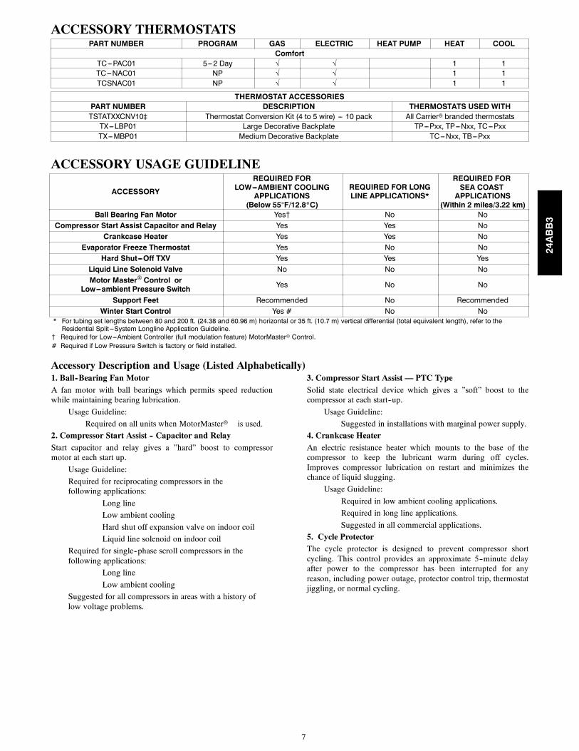
ACCESSORY THERMOSTATSPART NUMBER PROGRAM GAS ELECTRIC HEAT PUMP HEAT COOL
ComfortTC---PAC01 5---2 Day √ √ 1 1TC---NAC01 NP √ √ 1 1TCSNAC01 NP √ √ 1 1
THERMOSTAT ACCESSORIESPART NUMBER DESCRIPTION THERMOSTATS USED WITHTSTATXXCNV10‡ Thermostat Conversion Kit (4 to 5 wire) --- 10 pack All Carrier branded thermostatsTX---LBP01 Large Decorative Backplate TP---Pxx, TP---Nxx, TC---PxxTX---MBP01 Medium Decorative Backplate TC---Nxx, TB---Pxx
ACCESSORY USAGE GUIDELINE
ACCESSORY
REQUIRED FORLOW---AMBIENT COOLING
APPLICATIONS(Below 55F/12.8_C)
REQUIRED FOR LONGLINE APPLICATIONS*
REQUIRED FORSEA COASTAPPLICATIONS
(Within 2 miles/3.22 km)Ball Bearing Fan Motor Yes{ No No
Compressor Start Assist Capacitor and Relay Yes Yes NoCrankcase Heater Yes Yes No
Evaporator Freeze Thermostat Yes No NoHard Shut---Off TXV Yes Yes Yes
Liquid Line Solenoid Valve No No NoMotor Master Control or
Low---ambient Pressure Switch Yes No No
Support Feet Recommended No RecommendedWinter Start Control Yes # No No
* For tubing set lengths between 80 and 200 ft. (24.38 and 60.96 m) horizontal or 35 ft. (10.7 m) vertical differential (total equivalent length), refer to theResidential Split ---System Longline Application Guideline.
{ Required for Low---Ambient Controller (full modulation feature) MotorMasterr Control.# Required if Low Pressure Switch is factory or field installed.
Accessory Description and Usage (Listed Alphabetically)1. Ball--Bearing Fan MotorA fan motor with ball bearings which permits speed reductionwhile maintaining bearing lubrication.
Usage Guideline:
Required on all units when MotorMasterr is used.
2. Compressor Start Assist -- Capacitor and RelayStart capacitor and relay gives a ”hard” boost to compressormotor at each start up.
Usage Guideline:
Required for reciprocating compressors in thefollowing applications:
Long line
Low ambient cooling
Hard shut off expansion valve on indoor coil
Liquid line solenoid on indoor coil
Required for single--phase scroll compressors in thefollowing applications:
Long line
Low ambient cooling
Suggested for all compressors in areas with a history oflow voltage problems.
3. Compressor Start Assist — PTC TypeSolid state electrical device which gives a ”soft” boost to thecompressor at each start--up.
Usage Guideline:
Suggested in installations with marginal power supply.
4. Crankcase HeaterAn electric resistance heater which mounts to the base of thecompressor to keep the lubricant warm during off cycles.Improves compressor lubrication on restart and minimizes thechance of liquid slugging.
Usage Guideline:
Required in low ambient cooling applications.
Required in long line applications.
Suggested in all commercial applications.
5. Cycle ProtectorThe cycle protector is designed to prevent compressor shortcycling. This control provides an approximate 5--minute delayafter power to the compressor has been interrupted for anyreason, including power outage, protector control trip, thermostatjiggling, or normal cycling.
24ABB3
8
Accessory Description and Usage (Listed Alphabetically) (Continued)6. Evaporator Freeze ThermostatAn SPST temperature--actuated switch that stops unit operationwhen evaporator reaches freeze--up conditions.
Usage Guideline:
Required when low ambient kit has been added.
7. Low--Ambient Pressure Switch KitA long life pressure switch which is mounted to outdoor unitservice valve. It is designed to cycle the outdoor fan motor inorder to maintain head pressure within normal operating limits(approximately 100 psig to 225 psig). The control will maintainworking head pressure at low--ambient temperatures down to 0_F(--18_C) when properly installed.
Usage Guideline:
A Low--Ambient Pressure Switch or MotorMasterrLow--Ambient Controller must be used when cooling operation isused at outdoor temperatures below 55_F (12.8_C).
8. MotorMasterr Low--Ambient ControllerA fan--speed control device activated by a temperature sensor,designed to control condenser fan motor speed in response to thesaturated, condensing temperature during operation in coolingmode only. For outdoor temperatures down to --20_F (--28.9_C),it maintains condensing temperature at 100_F 10_F (37.8_C 5.5_C).
Usage Guideline:
A MotorMasterr Low Ambient Controller orLow--Ambient Pressure Switch must be used whencooling operation is used at outdoor temperaturesbelow 55_F (12.8_C).
Suggested for all commercial applications.
9. Outdoor Air Temperature SensorDesigned for use with Carrier Thermostats listed in thispublication. This device enables the thermostat to display theoutdoor temperature. This device also
is required to enable special thermostat features such as auxiliaryheat lock out.
Usage Guideline:
Suggested for all Carrier thermostats listed in thispublication.
10. Sound HoodWraparound sound reducing cover for the compressor. Reducesthe sound level by about 2 dBA.
Usage Guideline:
Suggested when unit is installed closer than 15 ft (4.57 m) toquiet areas, bedrooms, etc.
Suggested when unit is installed between two houses lessthan 10 ft (3.05 m) apart.
11. Support FeetFour stick--on plastic feet that raise the unit 4 in. (101.6 mm)above the mounting pad. This allows sand, dirt, and other debristo be flushed from the unit base, minimizing corrosion.
Usage Guideline:
Suggested in the following applications:
Coastal installations.
Windy areas or where debris is normally circulating.
Rooftop installations.
For improved sound ratings.
12. Thermostatic Expansion Valve (TXV)A modulating flow--control valve which meters refrigerant liquidflow rate into the evaporator in response to the superheat of therefrigerant gas leaving the evaporator.
Kit includes valve, adapter tubes, and external equalizer tube.Hard shut off types are available.
NOTE: When using a hard shut off TXV with single phasereciprocating compressors, a Compressor Start Assist Capacitorand Relay is required.
Usage Guideline:
Required to achieve AHRI ratings in certain equipment
combinations. Refer to combination ratings.
Hard shut off TXV or LLS required in air conditionerlong line applications.
Required for use on all zoning systems.
13. Time--Delay RelayAn SPST delay relay which briefly continues operation of indoorblower motor to provide additional cooling after the compressorcycles off.
NOTE: Most indoor unit controls include this feature. For thosethat do not, use the guideline below.
Usage Guideline:
For improved efficiency ratings for certaincombinations of indoor and outdoor units. Refer toAHRI Unitary Directory.
14. Winter Start ControlThis control is designed to alleviate nuisance opening of thelow--pressure switch by bypassing it for the first 3 minutes ofoperation.
24ABB3
9
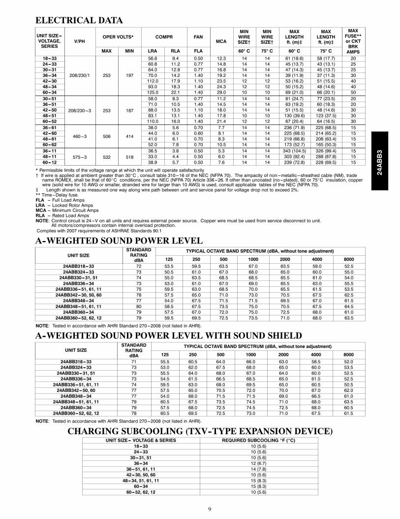
ELECTRICAL DATA
UNIT SIZE---VOLTAGE,SERIES
V/PHOPER VOLTS* COMPR FAN
MCA
MINWIRESIZE{
MINWIRESIZE{
MAXLENGTHft. (m)}
MAXLENGTHft. (m)}
MAXFUSE**or CKTBRKAMPSMAX MIN LRA RLA FLA 60 C 75 C 60 C 75 C
18---33
208/230/1 253 197
56.6 9.4 0.50 12.3 14 14 61 (18.6) 58 (17.7) 2024---33 60.8 11.2 0.77 14.8 14 14 45 (13.7) 43 (13.1) 2530---31 64.0 12.8 0.77 16.8 14 14 47 (14.3) 45 (13.7) 2536---34 70.0 14.2 1.40 19.2 14 14 39 (11.9) 37 (11.3) 3042---30 112.0 17.9 1.10 23.5 12 12 53 (16.2) 51 (15.5) 4048---34 93.0 18.3 1.40 24.3 12 12 50 (15.2) 48 (14.6) 4060---34 125.0 22.1 1.40 29.0 10 10 69 (21.0) 66 (20.1) 5030---51
208/230---3 253 187
58.0 8.3 0.77 11.2 14 14 81 (24.7) 77 (23.5) 2036---51 71.0 10.5 1.40 14.5 14 14 63 (19.2) 60 (18.3) 2042---50 88.0 13.5 1.10 18.0 14 14 51 (15.5) 48 (14.6) 3048---51 83.1 13.1 1.40 17.8 10 10 130 (39.6) 123 (37.5) 3060---52 110.0 16.0 1.40 21.4 12 12 67 (20.4) 64 (16.5) 3036---61
460---3 506 414
38.0 5.6 0.70 7.7 14 14 236 (71.9) 225 (68.5) 1542---60 44.0 6.0 0.60 8.1 14 14 225 (68.5) 214 (65.2) 1548---61 41.0 6.1 0.70 8.3 14 14 219 (66.8) 208 (63.4) 1560---62 52.0 7.8 0.70 10.5 14 14 173 (52.7) 165 (50.3) 1536---11
575---3 532 51836.5 3.8 0.50 5.3 14 14 343 (104.5) 326 (99.4) 15
48---11 33.0 4.4 0.50 6.0 14 14 303 (92.4) 288 (87.8) 1560---12 38.9 5.7 0.50 7.6 14 14 239 (72.8) 228 (69.5) 15
* Permissible limits of the voltage range at which the unit will operate satisfactorily{ If wire is applied at ambient greater than 30_C , consult table 310---16 of the NEC (NFPA 70). The ampacity of non---metallic---sheathed cable (NM), tradename ROMEX, shall be that of 60_C conditions, per the NEC (NFPA 70) Article 336---26. If other than uncoated (no---plated), 60 or 75_C insulation, copperwire (solid wire for 10 AWG or smaller, stranded wire for larger than 10 AWG) is used, consult applicable tables of the NEC (NFPA 70).
} Length shown is as measured one way along wire path between unit and service panel for voltage drop not to exceed 2%.** Time---Delay fuse.FLA --- Full Load AmpsLRA --- Locked Rotor AmpsMCA --- Minimum Circuit AmpsRLA --- Rated Load AmpsNOTE: Control circuit is 24---V on all units and requires external power source. Copper wire must be used from service disconnect to unit.
All motors/compressors contain internal overload protection.Complies with 2007 requirements of ASHRAE Standards 90.1
A--WEIGHTED SOUND POWER LEVEL
UNIT SIZESTANDARDRATINGdBA
TYPICAL OCTAVE BAND SPECTRUM (dBA, without tone adjustment)
125 250 500 1000 2000 4000 800024ABB318---33 72 53.5 59.5 63.5 67.0 63.5 59.0 52.524ABB324---33 73 50.5 61.0 67.0 68.0 65.0 60.0 55.024ABB330---31, 51 74 55.0 63.5 68.5 68.5 65.5 61.0 54.024ABB336---34 73 53.0 61.0 67.0 69.0 65.5 63.0 55.5
24ABB336---51, 61, 11 75 59.5 63.0 68.5 70.0 65.5 61.5 53.524ABB342---30, 50, 60 78 57.5 65.0 71.0 73.0 70.5 67.5 62.524ABB348---34 77 54.0 67.5 71.5 71.5 69.5 67.0 61.5
24ABB348---51, 61, 11 80 58.5 67.5 73.5 75.0 70.5 67.5 64.524ABB360---34 79 57.5 67.0 72.0 75.0 72.5 68.0 61.0
24ABB360---52, 62, 12 79 59.5 69.5 72.5 73.5 71.0 68.0 63.5
NOTE: Tested in accordance with AHRI Standard 270---2008 (not listed in AHRI).
A--WEIGHTED SOUND POWER LEVEL WITH SOUND SHIELD
UNIT SIZESTANDARDRATINGdBA
TYPICAL OCTAVE BAND SPECTRUM (dBA, without tone adjustment)
125 250 500 1000 2000 4000 800024ABB318---33 71 55.5 60.5 64.0 66.0 63.0 58.5 52.024ABB324---33 73 53.0 62.0 67.5 68.0 65.0 60.0 53.524ABB330---31, 51 73 55.5 64.0 68.0 67.0 64.0 60.0 52.524ABB336---34 73 54.5 61.5 66.5 68.5 65.0 61.5 52.5
24ABB336---51, 61, 11 74 59.5 63.0 68.0 69.5 65.0 60.5 50.524ABB342---50, 60 77 57.5 65.0 70.5 72.0 70.0 67.0 62.024ABB348---34 77 54.0 68.0 71.5 71.5 69.0 66.5 61.0
24ABB348---51, 61, 11 79 60.5 67.5 73.5 74.5 71.0 68.0 63.524ABB360---34 79 57.5 68.0 72.5 74.5 72.5 68.0 60.5
24ABB360---52, 62, 12 78 60.5 69.5 72.5 73.0 71.0 67.5 61.5
NOTE: Tested in accordance with AHRI Standard 270---2008 (not listed in AHRI).
CHARGING SUBCOOLING (TXV--TYPE EXPANSION DEVICE)UNIT SIZE--- VOLTAGE & SERIES REQUIRED SUBCOOLING _F (_C)
18---33 10 (5.6)24---33 10 (5.6)30---31, 51 10 (5.6)36---34 12 (6.7)
36---51, 61, 11 14 (7.8)42---30, 50, 60 10 (5.6)48---34, 51, 61, 11 15 (8.3)
60---34 15 (8.3)60---52, 62, 12 10 (5.6)
24ABB3
10
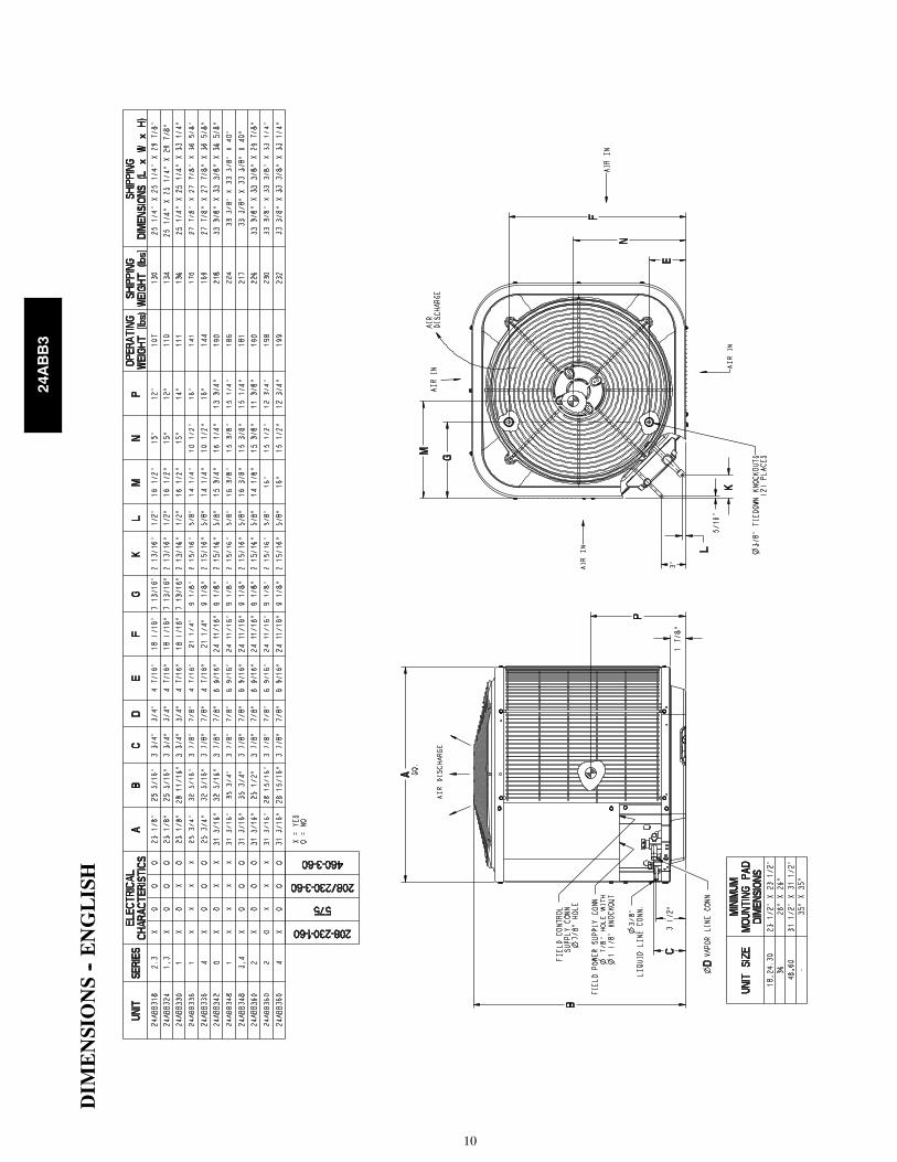
DIM
EN
SIO
NS
--E
NG
LIS
H
24ABB3
11
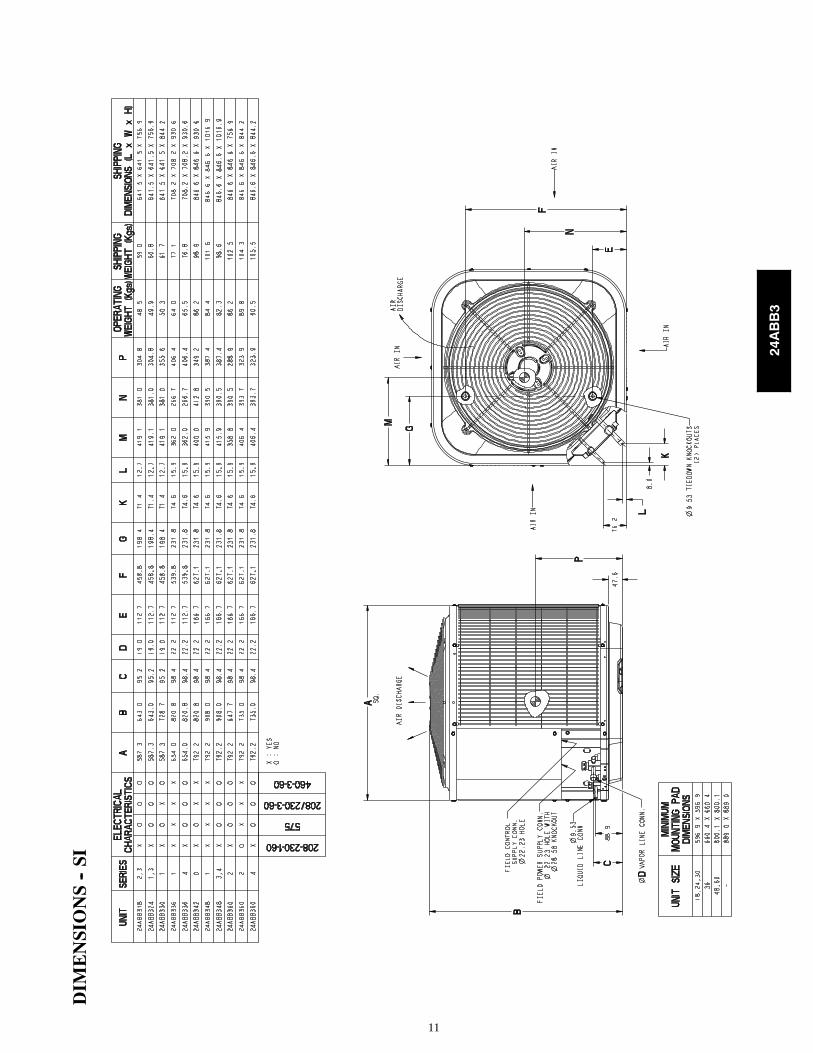
DIM
EN
SIO
NS
--SI
24ABB3
12
CL
EA
RA
NC
ES
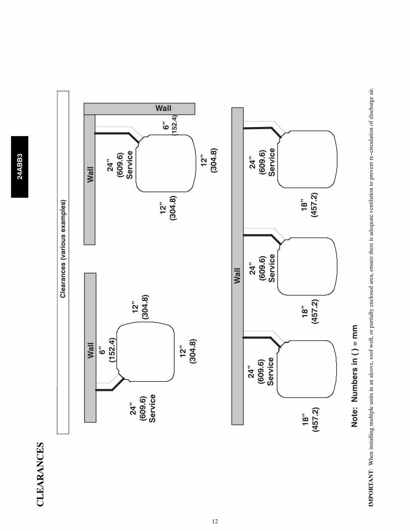
Cle
aran
ces
(var
iou
s ex
amp
les)
Wal
l6”
(1
52.4
)
24”
(609
.6)
Ser
vice
Wal
l
Wal
l
Wall
12”
(304
.8)
12”
(304
.8)
18”
(457
.2)
24”
(609
.6)
Ser
vice
6”
(152
.4)
12”
(304
.8)
24”
(609
.6)
Ser
vice
24”
(609
.6)
Ser
vice
24”
(609
.6)
Ser
vice
No
te:
Nu
mb
ers
in (
) =
mm
18”
(457
.2)
18”
(457
.2)
12”
(304
.8)
IMP
OR
TA
NT
:W
hen
inst
allin
gm
ultip
leun
itsin
anal
cove
,roo
fw
ell,
orpa
rtia
llyen
clos
edar
ea,e
nsur
eth
ere
isad
equa
teve
ntila
tion
topr
even
tre-
-cir
cula
tion
ofdi
scha
rge
air.
24ABB3
13
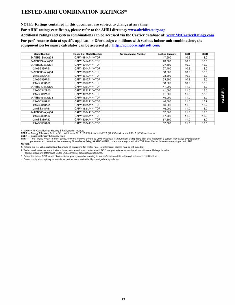
TESTED AHRI COMBINATION RATINGS*
NOTE: Ratings contained in this document are subject to change at any time.For AHRI ratings certificates, please refer to the AHRI directory www.ahridirectory.orgAdditional ratings and system combinations can be accessed via the Carrier database at: www.MyCarrierRatings.com
For performance data at specific application &/or design conditions with various indoor unit combinations, theequipment performance calculator can be accessed at : http://rpmob.wrightsoft.com/
Model Number Indoor Coil Model Number Furnace Model Number Cooling Capacity EER SEER24ABB318(A,W)33 CAP**1814A**+TDR 17,600 10.9 13.024ABB324(A,W)33 CAP**2414A**+TDR 23,000 10.9 13.024ABB330(A,W)31 CAP**3014A**+TDR 27,400 10.9 13.024ABB330A51 CAP**3014A**+TDR 27,400 10.8 13.024ABB336(A,W)34 CAP**3617A**+TDR 33,800 10.9 13.024ABB336A11 CAP**3617A**+TDR 33,800 10.9 13.024ABB336A51 CAP**3617A**+TDR 33,800 10.9 13.024ABB336A61 CAP**3617A**+TDR 33,800 10.9 13.024ABB342(A,W)30 CAP**4221A**+TDR 41,000 11.0 13.024ABB342A50 CAP**4221A**+TDR 41,000 11.0 13.024ABB342A60 CAP**4221A**+TDR 41,000 11.0 13.024ABB348(A,W)34 CAP**4821A**+TDR 46,000 11.0 13.024ABB348A11 CAP**4821A**+TDR 46,000 11.0 13.224ABB348A51 CAP**4821A**+TDR 46,000 11.0 13.224ABB348A61 CAP**4821A**+TDR 46,000 11.0 13.224ABB360(A,W)34 CAP**6024A**+TDR 57,500 11.0 13.024ABB360A12 CAP**6024A**+TDR 57,500 11.0 13.024ABB360A52 CAP**6024A**+TDR 57,500 11.0 13.024ABB360A62 CAP**6024A**+TDR 57,500 11.0 13.0
* AHRI = Air Conditioning, Heating & Refrigeration InstituteEERA — Energy Efficiency Ratio --- ’A’ conditions --- 80_F (26.6_C) indoor db/67_F (19.4_C) indoor wb & 95_F (35_C) outdoor wb.SEER — Seasonal Energy Efficiency RatioTDR — Time---Delay Relay. In most cases, only one method should be used to achieve TDR function. Using more than one method in a system may cause degradation in
performance. Use either the accessory Time---Delay Relay, KAATD0101TDR, or a furnace equipped with TDR. Most Carrier furnaces are equipped with TDR.NOTES:1. Ratings are net values reflecting the effects of circulating fan motor heat. Supplemental electric heat is not included.2. Tested outdoor/indoor combinations have been tested in accordance with DOE test procedures for central air conditioners. Ratings for othercombinations are determined under DOE computer simulation procedures.
3. Determine actual CFM values obtainable for your system by referring to fan performance data in fan coil or furnace coil literature.4. Do not apply with capillary tube coils as performance and reliability are significantly affected.
24ABB3
14
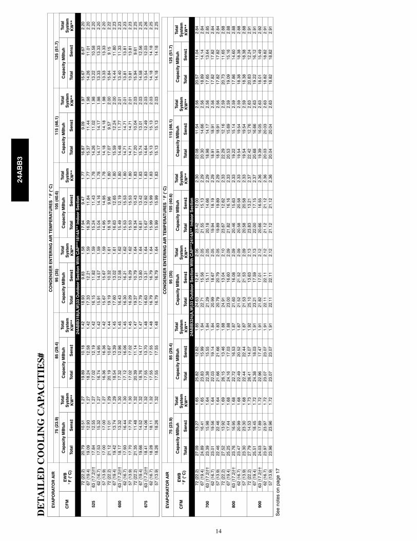
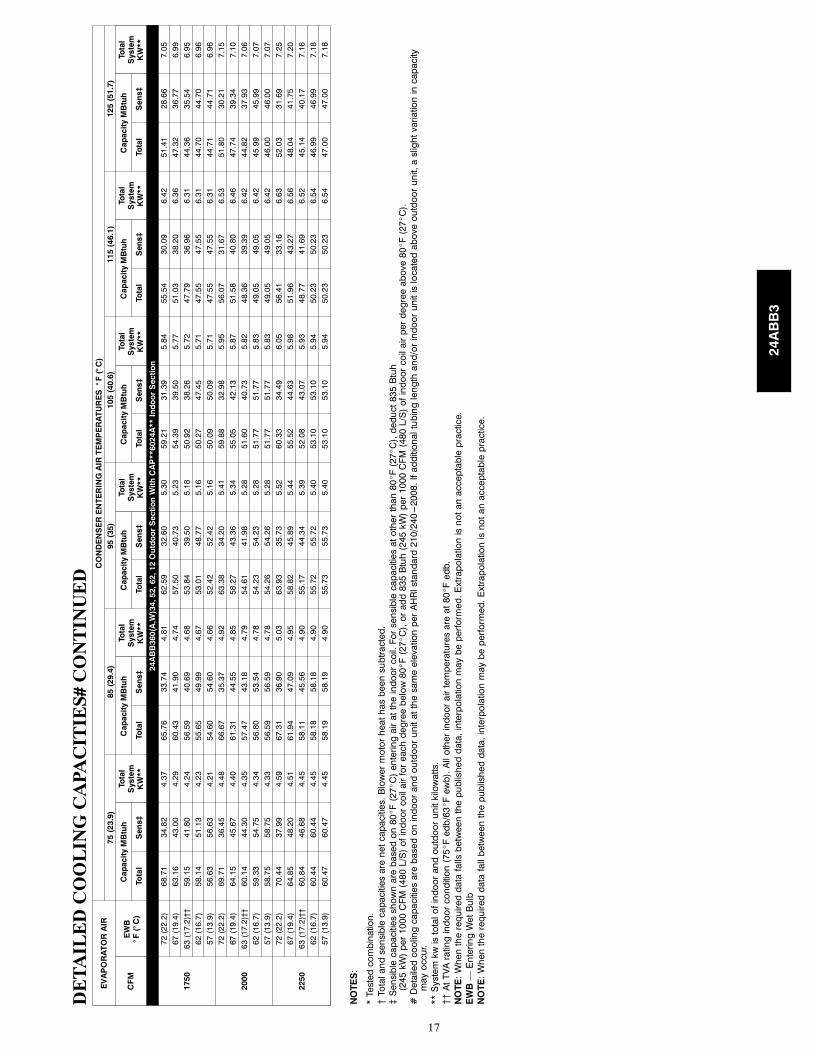
DE
TA
ILE
DC
OO
LIN
GC
APA
CIT
IES#
EVAPORATORAIR
CONDENSERENTERINGAIRTEMPERATURES°F(°C)
75(23.9)
85(29.4)
95(35)
105(40.6)
115(46.1)
125(51.7)
CFM
EWB
°F(°C)
CapacityMBtuh
Total
System
KW**
CapacityMBtuh
Total
System
KW**
CapacityMBtuh
Total
System
KW**
CapacityMBtuh
Total
System
KW**
CapacityMBtuh
Total
System
KW**
CapacityMBtuh
Total
System
KW**
Total
Sens‡
Total
Sens‡
Total
Sens‡
Total
Sens‡
Total
Sens‡
Total
Sens‡
24ABB318(A,W)33OutdoorSectionWithCAP**1814A**IndoorSection
525
72(22.2)
20.79
10.51
1.27
19.89
10.18
1.42
18.93
9.83
1.58
17.94
9.47
1.77
16.87
9.09
1.97
15.67
8.67
2.20
67(19.4)
19.09
12.93
1.27
18.24
12.58
1.42
17.33
12.21
1.59
16.39
11.84
1.77
15.37
11.44
1.98
14.26
11.01
2.20
63(17.2)††
17.84
12.55
1.27
17.02
12.19
1.42
16.15
11.82
1.59
15.24
11.43
1.78
14.26
11.02
1.98
13.22
10.58
2.20
62(16.7)
17.53
15.32
1.27
16.74
14.95
1.42
15.91
14.57
1.59
15.04
14.16
1.78
14.17
14.17
1.98
13.33
13.33
2.20
57(13.9)
17.00
17.00
1.27
16.36
16.36
1.42
15.67
15.67
1.59
14.95
14.95
1.78
14.18
14.18
1.98
13.33
13.33
2.20
600
72(22.2)
21.12
11.01
1.29
20.19
10.67
1.44
19.19
10.32
1.61
18.18
9.96
1.80
17.07
9.57
2.00
15.84
9.15
2.22
67(19.4)
19.42
13.74
1.29
18.54
13.39
1.45
17.60
13.02
1.61
16.63
12.65
1.80
15.59
12.24
2.00
14.44
11.80
2.23
63(17.2)††
18.17
13.32
1.30
17.32
12.96
1.45
16.43
12.58
1.62
15.49
12.19
1.80
14.48
11.77
2.01
13.40
11.33
2.23
62(16.7)
17.93
16.44
1.30
17.12
16.06
1.45
16.30
16.21
1.62
15.53
15.53
1.80
14.71
14.71
2.01
13.81
13.81
2.23
57(13.9)
17.70
17.70
1.30
17.02
17.02
1.45
16.29
16.29
1.62
15.53
15.53
1.80
14.71
14.71
2.01
13.81
13.81
2.23
675
72(22.2)
21.35
11.48
1.32
20.39
11.14
1.47
19.37
10.79
1.64
18.34
10.43
1.83
17.20
10.04
2.03
15.94
9.61
2.25
67(19.4)
19.66
14.52
1.32
18.76
14.17
1.47
17.79
13.80
1.64
16.81
13.42
1.83
15.74
13.01
2.03
14.58
12.56
2.25
63(17.2)††
18.41
14.06
1.32
17.55
13.70
1.48
16.63
13.31
1.64
15.67
12.92
1.83
14.64
12.49
2.03
13.54
12.03
2.26
62(16.7)
18.28
18.11
1.32
17.55
17.55
1.48
16.79
16.79
1.64
15.99
15.99
1.83
15.13
15.13
2.03
14.18
14.18
2.25
57(13.9)
18.26
18.26
1.32
17.55
17.55
1.48
16.79
16.79
1.64
15.99
15.99
1.83
15.13
15.13
2.03
14.18
14.18
2.25
EVAPORATORAIR
CONDENSERENTERINGAIRTEMPERATURES°F(°C)
75(23.9)
85(29.4)
95(35)
105(40.6)
115(46.1)
125(51.7)
CFM
EWB
°F(°C)
CapacityMBtuh
Total
System
KW**
CapacityMBtuh
Total
System
KW**
CapacityMBtuh
Total
System
KW**
CapacityMBtuh
Total
System
KW**
CapacityMBtuh
Total
System
KW**
CapacityMBtuh
Total
System
KW**
Total
Sens‡
Total
Sens‡
Total
Sens‡
Total
Sens‡
Total
Sens‡
Total
Sens‡
24ABB324(A,W)33OutdoorSectionWithCAP**2414A**IndoorSection
700
72(22.2)
27.09
13.27
1.65
25.82
12.82
1.85
24.63
12.41
2.06
23.42
12.00
2.30
22.08
11.54
2.56
20.57
11.04
2.84
67(19.4)
24.89
16.41
1.65
23.83
15.99
1.84
22.71
15.56
2.05
21.55
15.13
2.29
20.30
14.66
2.56
18.89
14.14
2.84
63(17.2)††
23.39
15.98
1.64
22.38
15.55
1.84
21.29
15.11
2.05
20.18
14.66
2.29
18.98
14.17
2.56
17.65
13.64
2.85
62(16.7)
23.01
19.56
1.64
22.03
19.14
1.84
20.99
18.67
2.05
19.94
18.19
2.29
18.91
18.91
2.56
17.82
17.82
2.84
57(13.9)
22.46
22.46
1.64
21.66
21.66
1.83
20.79
20.79
2.05
19.89
19.89
2.29
18.91
18.91
2.56
17.82
17.82
2.84
800
72(22.2)
27.52
13.92
1.69
26.15
13.46
1.88
24.91
13.04
2.10
23.67
12.62
2.33
22.29
12.16
2.59
20.73
11.65
2.88
67(19.4)
25.25
17.44
1.68
24.16
17.03
1.88
23.00
16.60
2.09
21.82
16.16
2.33
20.53
15.69
2.59
19.09
15.16
2.88
63(17.2)††
23.76
16.95
1.68
22.72
16.53
1.87
21.60
16.08
2.09
20.46
15.63
2.33
19.22
15.14
2.59
17.86
14.60
2.88
62(16.7)
23.47
20.99
1.68
22.49
20.52
1.87
21.52
21.52
2.09
20.58
20.58
2.33
19.54
19.54
2.59
18.38
18.38
2.88
57(13.9)
23.30
23.30
1.68
22.44
22.44
1.87
21.53
21.53
2.09
20.58
20.58
2.33
19.54
19.54
2.59
18.38
18.38
2.88
900
72(22.2)
27.79
14.53
1.73
26.41
14.07
1.92
25.10
13.63
2.13
23.83
13.21
2.37
22.42
12.76
2.63
20.83
12.24
2.91
67(19.4)
25.51
18.45
1.72
24.38
18.03
1.91
23.21
17.59
2.13
22.00
17.15
2.37
20.68
16.66
2.63
19.22
16.12
2.91
63(17.2)††
24.03
17.89
1.72
22.96
17.47
1.91
21.82
17.01
2.12
20.66
16.55
2.36
19.39
16.05
2.63
18.01
15.49
2.92
62(16.7)
23.97
23.97
1.72
23.07
23.07
1.91
22.11
22.11
2.12
21.12
21.12
2.36
20.03
20.03
2.63
18.82
18.82
2.91
57(13.9)
23.96
23.96
1.72
23.07
23.07
1.91
22.11
22.11
2.12
21.12
21.12
2.36
20.04
20.04
2.63
18.82
18.82
2.91
Seenotesonpage17
24ABB3
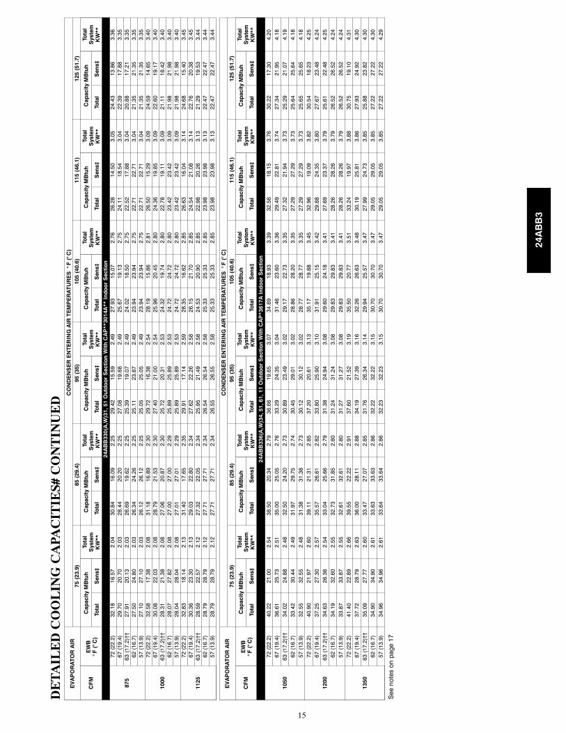
15
DE
TA
ILE
DC
OO
LIN
GC
APA
CIT
IES#
CO
NT
INU
ED
EVAPORATORAIR
CONDENSERENTERINGAIRTEMPERATURES°F(°C)
75(23.9)
85(29.4)
95(35)
105(40.6)
115(46.1)
125(51.7)
CFM
EWB
°F(°C)
CapacityMBtuh
Total
System
KW**
CapacityMBtuh
Total
System
KW**
CapacityMBtuh
Total
System
KW**
CapacityMBtuh
Total
System
KW**
CapacityMBtuh
Total
System
KW**
CapacityMBtuh
Total
System
KW**
Total
Sens‡
Total
Sens‡
Total
Sens‡
Total
Sens‡
Total
Sens‡
Total
Sens‡
24ABB330(A,W)31,51OutdoorSectionWithCAP**3014A**IndoorSection
875
72(22.2)
32.18
16.57
2.04
30.84
16.09
2.25
29.42
15.59
2.49
27.93
15.07
2.76
26.28
14.50
3.05
24.43
13.86
3.36
67(19.4)
29.70
20.70
2.03
28.44
20.20
2.25
27.08
19.68
2.49
25.67
19.13
2.75
24.11
18.54
3.04
22.39
17.88
3.35
63(17.2)††
27.91
20.13
2.03
26.69
19.62
2.25
25.39
19.07
2.49
24.02
18.50
2.75
22.52
17.88
3.04
20.88
17.21
3.35
62(16.7)
27.50
24.80
2.03
26.34
24.26
2.25
25.11
23.67
2.49
23.94
23.94
2.75
22.71
22.71
3.04
21.35
21.35
3.35
57(13.9)
27.10
27.10
2.03
26.12
26.12
2.25
25.05
25.05
2.49
23.94
23.94
2.75
22.71
22.71
3.04
21.35
21.35
3.35
1000
72(22.2)
32.58
17.38
2.08
31.18
16.89
2.30
29.72
16.38
2.54
28.19
15.86
2.81
26.50
15.29
3.09
24.59
14.65
3.40
67(19.4)
30.08
22.03
2.08
28.79
21.53
2.30
27.40
21.00
2.54
25.96
20.45
2.80
24.36
19.85
3.09
22.60
19.17
3.40
63(17.2)††
28.31
21.38
2.08
27.06
20.87
2.30
25.72
20.31
2.53
24.32
19.74
2.80
22.78
19.11
3.09
21.11
18.42
3.40
62(16.7)
28.07
27.82
2.08
27.00
27.00
2.29
25.89
25.89
2.53
24.72
24.72
2.80
23.42
23.42
3.09
21.98
21.98
3.40
57(13.9)
28.04
28.04
2.08
27.01
27.01
2.29
25.89
25.89
2.53
24.72
24.72
2.80
23.42
23.42
3.09
21.98
21.98
3.40
1125
72(22.2)
32.83
18.14
2.13
31.40
17.65
2.35
29.91
17.14
2.59
28.35
16.62
2.85
26.63
16.04
3.14
24.68
15.40
3.45
67(19.4)
30.36
23.30
2.13
29.03
22.80
2.34
27.62
22.26
2.58
26.15
21.70
2.85
24.54
21.08
3.14
22.76
20.38
3.45
63(17.2)††
28.59
22.57
2.12
27.32
22.05
2.34
25.95
21.49
2.58
24.53
20.90
2.85
22.98
20.26
3.13
21.29
19.53
3.44
62(16.7)
28.79
28.79
2.12
27.71
27.71
2.34
26.54
26.54
2.58
25.33
25.33
2.85
23.98
23.98
3.13
22.47
22.47
3.44
57(13.9)
28.79
28.79
2.12
27.71
27.71
2.34
26.55
26.55
2.58
25.33
25.33
2.85
23.98
23.98
3.13
22.47
22.47
3.44
EVAPORATORAIR
CONDENSERENTERINGAIRTEMPERATURES°F(°C)
75(23.9)
85(29.4)
95(35)
105(40.6)
115(46.1)
125(51.7)
CFM
EWB
°F(°C)
CapacityMBtuh
Total
System
KW**
CapacityMBtuh
Total
System
KW**
CapacityMBtuh
Total
System
KW**
CapacityMBtuh
Total
System
KW**
CapacityMBtuh
Total
System
KW**
CapacityMBtuh
Total
System
KW**
Total
Sens‡
Total
Sens‡
Total
Sens‡
Total
Sens‡
Total
Sens‡
Total
Sens‡
24ABB336(A,W)34,51,61,11OutdoorSectionWithCAP*3617AIndoorSection
1050
72(22.2)
40.22
21.00
2.54
38.50
20.34
2.79
36.66
19.65
3.07
34.69
18.93
3.39
32.56
18.15
3.76
30.22
17.30
4.20
67(19.4)
36.61
25.73
2.51
35.00
25.05
2.76
33.29
24.35
3.04
31.46
23.60
3.36
29.49
22.81
3.74
27.34
21.95
4.18
63(17.2)††
34.02
24.88
2.48
32.50
24.20
2.73
30.89
23.49
3.02
29.17
22.73
3.35
27.32
21.94
3.73
25.29
21.07
4.19
62(16.7)
33.42
30.44
2.49
31.97
29.75
2.74
30.45
29.01
3.02
28.86
28.20
3.35
27.29
27.29
3.73
25.64
25.64
4.18
57(13.9)
32.55
32.55
2.48
31.38
31.38
2.73
30.12
30.12
3.02
28.77
28.77
3.35
27.29
27.29
3.73
25.65
25.65
4.18
1200
72(22.2)
40.90
21.97
2.60
39.11
21.31
2.85
37.20
20.61
3.13
35.17
19.88
3.45
32.96
19.09
3.82
30.54
18.23
4.25
67(19.4)
37.25
27.30
2.57
35.57
26.61
2.82
33.80
25.90
3.10
31.91
25.15
3.42
29.88
24.35
3.80
27.67
23.48
4.24
63(17.2)††
34.63
26.36
2.54
33.04
25.66
2.79
31.38
24.94
3.08
29.60
24.18
3.41
27.69
23.37
3.79
25.61
22.48
4.25
62(16.7)
34.19
32.60
2.55
32.73
31.85
2.80
31.24
31.24
3.08
29.83
29.83
3.41
28.26
28.26
3.79
26.52
26.52
4.24
57(13.9)
33.87
33.87
2.55
32.61
32.61
2.80
31.27
31.27
3.08
29.83
29.83
3.41
28.26
28.26
3.79
26.52
26.52
4.24
1350
72(22.2)
41.40
22.89
2.66
39.55
22.22
2.91
37.60
21.52
3.19
35.50
20.77
3.51
33.24
19.97
3.88
30.75
19.10
4.31
67(19.4)
37.72
28.79
2.63
36.00
28.11
2.88
34.19
27.39
3.16
32.26
26.63
3.48
30.19
25.81
3.86
27.93
24.92
4.30
63(17.2)††
35.09
27.77
2.60
33.47
27.07
2.85
31.76
26.34
3.14
29.94
25.57
3.47
27.99
24.73
3.85
25.88
23.82
4.30
62(16.7)
34.90
34.90
2.61
33.63
33.63
2.86
32.22
32.22
3.15
30.70
30.70
3.47
29.05
29.05
3.85
27.22
27.22
4.30
57(13.9)
34.96
34.96
2.61
33.64
33.64
2.86
32.23
32.23
3.15
30.70
30.70
3.47
29.05
29.05
3.85
27.22
27.22
4.29
Seenotesonpage17
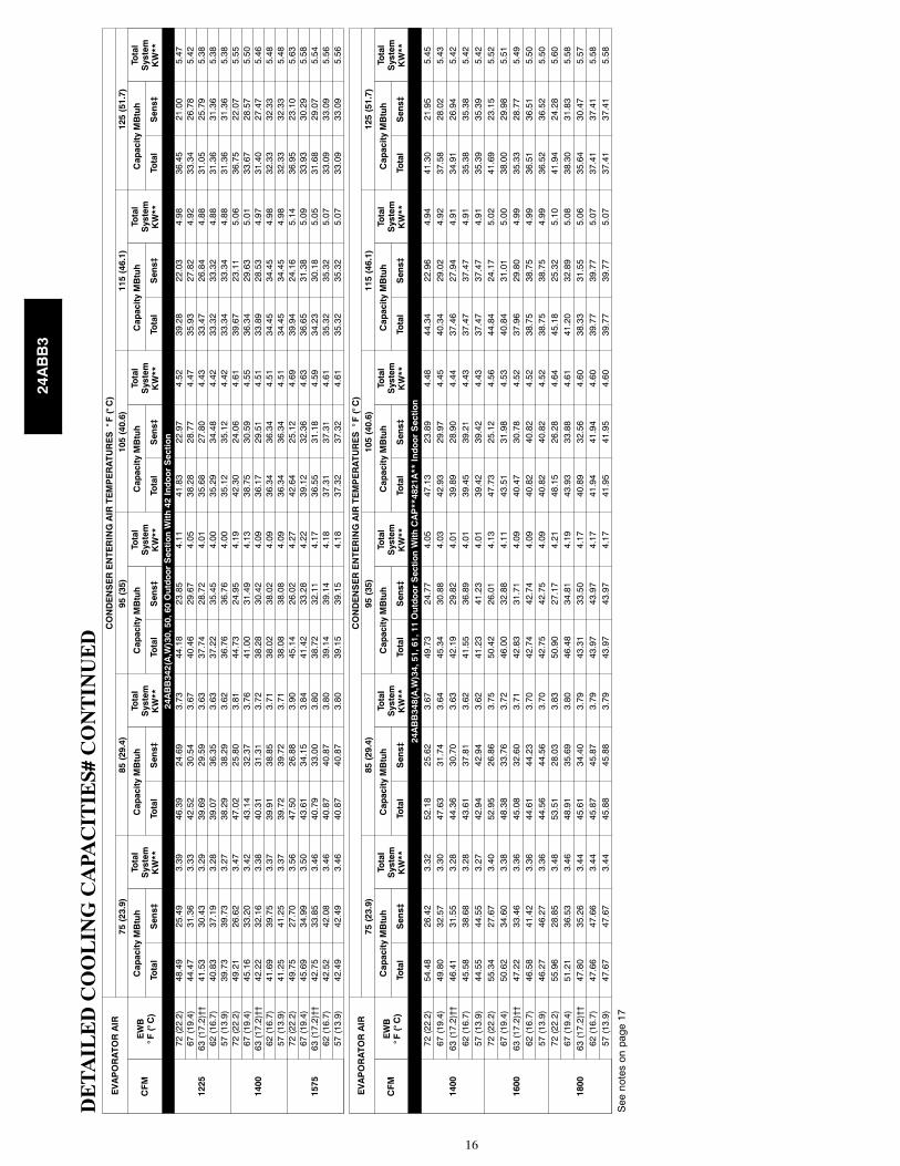
24ABB3
16
DE
TA
ILE
DC
OO
LIN
GC
APA
CIT
IES#
CO
NT
INU
ED
EVAPORATORAIR
CONDENSERENTERINGAIRTEMPERATURES°F(°C)
75(23.9)
85(29.4)
95(35)
105(40.6)
115(46.1)
125(51.7)
CFM
EWB
°F(°C)
CapacityMBtuh
Total
System
KW**
CapacityMBtuh
Total
System
KW**
CapacityMBtuh
Total
System
KW**
CapacityMBtuh
Total
System
KW**
CapacityMBtuh
Total
System
KW**
CapacityMBtuh
Total
System
KW**
Total
Sens‡
Total
Sens‡
Total
Sens‡
Total
Sens‡
Total
Sens‡
Total
Sens‡
24ABB342(A,W)30,50,60OutdoorSectionWith42IndoorSection
1225
72(22.2)
48.49
25.49
3.39
46.39
24.69
3.73
44.18
23.85
4.11
41.83
22.97
4.52
39.28
22.03
4.98
36.45
21.00
5.47
67(19.4)
44.47
31.36
3.33
42.52
30.54
3.67
40.46
29.67
4.05
38.28
28.77
4.47
35.93
27.82
4.92
33.34
26.78
5.42
63(17.2)††
41.53
30.43
3.29
39.69
29.59
3.63
37.74
28.72
4.01
35.68
27.80
4.43
33.47
26.84
4.88
31.05
25.79
5.38
62(16.7)
40.83
37.19
3.28
39.07
36.35
3.63
37.22
35.45
4.00
35.29
34.48
4.42
33.32
33.32
4.88
31.36
31.36
5.38
57(13.9)
39.73
39.73
3.27
38.29
38.29
3.62
36.76
36.76
4.00
35.12
35.12
4.42
33.34
33.34
4.88
31.36
31.36
5.38
1400
72(22.2)
49.21
26.62
3.47
47.02
25.80
3.81
44.73
24.95
4.19
42.30
24.06
4.61
39.67
23.11
5.06
36.75
22.07
5.55
67(19.4)
45.16
33.20
3.42
43.14
32.37
3.76
41.00
31.49
4.13
38.75
30.59
4.55
36.34
29.63
5.01
33.67
28.57
5.50
63(17.2)††
42.22
32.16
3.38
40.31
31.31
3.72
38.28
30.42
4.09
36.17
29.51
4.51
33.89
28.53
4.97
31.40
27.47
5.46
62(16.7)
41.69
39.75
3.37
39.91
38.85
3.71
38.02
38.02
4.09
36.34
36.34
4.51
34.45
34.45
4.98
32.33
32.33
5.48
57(13.9)
41.25
41.25
3.37
39.72
39.72
3.71
38.08
38.08
4.09
36.34
36.34
4.51
34.45
34.45
4.98
32.33
32.33
5.48
1575
72(22.2)
49.75
27.70
3.56
47.50
26.88
3.90
45.14
26.02
4.27
42.64
25.12
4.69
39.94
24.16
5.14
36.95
23.10
5.63
67(19.4)
45.69
34.99
3.50
43.61
34.15
3.84
41.42
33.28
4.22
39.12
32.36
4.63
36.65
31.38
5.09
33.93
30.29
5.58
63(17.2)††
42.75
33.85
3.46
40.79
33.00
3.80
38.72
32.11
4.17
36.55
31.18
4.59
34.23
30.18
5.05
31.68
29.07
5.54
62(16.7)
42.52
42.08
3.46
40.87
40.87
3.80
39.14
39.14
4.18
37.31
37.31
4.61
35.32
35.32
5.07
33.09
33.09
5.56
57(13.9)
42.49
42.49
3.46
40.87
40.87
3.80
39.15
39.15
4.18
37.32
37.32
4.61
35.32
35.32
5.07
33.09
33.09
5.56
EVAPORATORAIR
CONDENSERENTERINGAIRTEMPERATURES°F(°C)
75(23.9)
85(29.4)
95(35)
105(40.6)
115(46.1)
125(51.7)
CFM
EWB
°F(°C)
CapacityMBtuh
Total
System
KW**
CapacityMBtuh
Total
System
KW**
CapacityMBtuh
Total
System
KW**
CapacityMBtuh
Total
System
KW**
CapacityMBtuh
Total
System
KW**
CapacityMBtuh
Total
System
KW**
Total
Sens‡
Total
Sens‡
Total
Sens‡
Total
Sens‡
Total
Sens‡
Total
Sens‡
24ABB348(A,W)34,51,61,11OutdoorSectionWithCAP**4821A**IndoorSection
1400
72(22.2)
54.48
26.42
3.32
52.18
25.62
3.67
49.73
24.77
4.05
47.13
23.89
4.48
44.34
22.96
4.94
41.30
21.95
5.45
67(19.4)
49.80
32.57
3.30
47.63
31.74
3.64
45.34
30.88
4.03
42.93
29.97
4.45
40.34
29.02
4.92
37.58
28.02
5.43
63(17.2)††
46.41
31.55
3.28
44.36
30.70
3.63
42.19
29.82
4.01
39.89
28.90
4.44
37.46
27.94
4.91
34.91
26.94
5.42
62(16.7)
45.58
38.68
3.28
43.61
37.81
3.62
41.55
36.89
4.01
39.45
39.21
4.43
37.47
37.47
4.91
35.38
35.38
5.42
57(13.9)
44.55
44.55
3.27
42.94
42.94
3.62
41.23
41.23
4.01
39.42
39.42
4.43
37.47
37.47
4.91
35.39
35.39
5.42
1600
72(22.2)
55.34
27.67
3.40
52.95
26.86
3.75
50.42
26.01
4.13
47.73
25.12
4.56
44.84
24.17
5.02
41.69
23.15
5.52
67(19.4)
50.62
34.60
3.38
48.38
33.76
3.72
46.00
32.88
4.11
43.51
31.98
4.53
40.84
31.01
5.00
38.00
29.98
5.51
63(17.2)††
47.22
33.46
3.36
45.08
32.60
3.71
42.83
31.71
4.09
40.47
30.78
4.52
37.96
29.80
4.99
35.33
28.77
5.49
62(16.7)
46.58
41.42
3.36
44.61
44.23
3.70
42.74
42.74
4.09
40.82
40.82
4.52
38.75
38.75
4.99
36.51
36.51
5.50
57(13.9)
46.27
46.27
3.36
44.56
44.56
3.70
42.75
42.75
4.09
40.82
40.82
4.52
38.75
38.75
4.99
36.52
36.52
5.50
1800
72(22.2)
55.96
28.85
3.48
53.51
28.03
3.83
50.90
27.17
4.21
48.15
26.28
4.64
45.18
25.32
5.10
41.94
24.28
5.60
67(19.4)
51.21
36.53
3.46
48.91
35.69
3.80
46.48
34.81
4.19
43.93
33.88
4.61
41.20
32.89
5.08
38.30
31.83
5.58
63(17.2)††
47.80
35.26
3.44
45.61
34.40
3.79
43.31
33.50
4.17
40.89
32.56
4.60
38.33
31.55
5.06
35.64
30.47
5.57
62(16.7)
47.66
47.66
3.44
45.87
45.87
3.79
43.97
43.97
4.17
41.94
41.94
4.60
39.77
39.77
5.07
37.41
37.41
5.58
57(13.9)
47.67
47.67
3.44
45.88
45.88
3.79
43.97
43.97
4.17
41.95
41.95
4.60
39.77
39.77
5.07
37.41
37.41
5.58
Seenotesonpage17
24ABB3
17
DE
TA
ILE
DC
OO
LIN
GC
APA
CIT
IES#
CO
NT
INU
ED
EVAPORATORAIR
CONDENSERENTERINGAIRTEMPERATURES°F(°C)
75(23.9)
85(29.4)
95(35)
105(40.6)
115(46.1)
125(51.7)
CFM
EWB
°F(°C)
CapacityMBtuh
Total
System
KW**
CapacityMBtuh
Total
System
KW**
CapacityMBtuh
Total
System
KW**
CapacityMBtuh
Total
System
KW**
CapacityMBtuh
Total
System
KW**
CapacityMBtuh
Total
System
KW**
Total
Sens‡
Total
Sens‡
Total
Sens‡
Total
Sens‡
Total
Sens‡
Total
Sens‡
24ABB360(A,W)34,52,62,12OutdoorSectionWithCAP**6024A**IndoorSection
1750
72(22.2)
68.71
34.82
4.37
65.76
33.74
4.81
62.59
32.60
5.30
59.21
31.39
5.84
55.54
30.09
6.42
51.41
28.66
7.05
67(19.4)
63.16
43.00
4.29
60.43
41.90
4.74
57.50
40.73
5.23
54.39
39.50
5.77
51.03
38.20
6.36
47.32
36.77
6.99
63(17.2)††
59.15
41.80
4.24
56.59
40.69
4.68
53.84
39.50
5.18
50.92
38.26
5.72
47.79
36.96
6.31
44.36
35.54
6.95
62(16.7)
58.14
51.13
4.23
55.65
49.99
4.67
53.01
48.77
5.16
50.27
47.45
5.71
47.55
47.55
6.31
44.70
44.70
6.96
57(13.9)
56.63
56.63
4.21
54.60
54.60
4.66
52.42
52.42
5.16
50.09
50.09
5.71
47.55
47.55
6.31
44.71
44.71
6.96
2000
72(22.2)
69.71
36.45
4.48
66.67
35.37
4.92
63.38
34.20
5.41
59.88
32.98
5.95
56.07
31.67
6.53
51.80
30.21
7.15
67(19.4)
64.15
45.67
4.40
61.31
44.55
4.85
58.27
43.36
5.34
55.05
42.13
5.87
51.58
40.80
6.46
47.74
39.34
7.10
63(17.2)††
60.14
44.30
4.35
57.47
43.18
4.79
54.61
41.98
5.28
51.60
40.73
5.82
48.36
39.39
6.42
44.82
37.93
7.06
62(16.7)
59.33
54.75
4.34
56.80
53.54
4.78
54.23
54.23
5.28
51.77
51.77
5.83
49.05
49.05
6.42
45.99
45.99
7.07
57(13.9)
58.75
58.75
4.33
56.59
56.59
4.78
54.26
54.26
5.28
51.77
51.77
5.83
49.05
49.05
6.42
46.00
46.00
7.07
2250
72(22.2)
70.44
37.99
4.59
67.31
36.90
5.03
63.93
35.73
5.52
60.33
34.49
6.05
56.41
33.16
6.63
52.03
31.69
7.25
67(19.4)
64.85
48.20
4.51
61.94
47.09
4.95
58.82
45.89
5.44
55.52
44.63
5.98
51.96
43.27
6.56
48.04
41.75
7.20
63(17.2)††
60.84
46.68
4.45
58.11
45.56
4.90
55.17
44.34
5.39
52.08
43.07
5.93
48.77
41.69
6.52
45.14
40.17
7.16
62(16.7)
60.44
60.44
4.45
58.18
58.18
4.90
55.72
55.72
5.40
53.10
53.10
5.94
50.23
50.23
6.54
46.99
46.99
7.18
57(13.9)
60.47
60.47
4.45
58.19
58.19
4.90
55.73
55.73
5.40
53.10
53.10
5.94
50.23
50.23
6.54
47.00
47.00
7.18
NOTES:
*Testedcombination.
{Totalandsensiblecapacitiesarenetcapacities.Blowermotorheathasbeensubtracted.
}Sensiblecapacitiesshownarebasedon80_F(27_C)enteringairattheindoorcoil.Forsensiblecapacitiesatotherthan80_F(27_C),deduct835Btuh
(245kW)per1000CFM(480L/S)ofindoorcoilairforeachdegreebelow80_F(27_C),oradd835Btuh(245kW)per1000CFM(480L/S)ofindoorcoilairperdegreeabove80_F(27_C).
#DetailedcoolingcapacitiesarebasedonindoorandoutdoorunitatthesameelevationperAHRIstandard210/240---2008.Ifadditionaltubinglengthand/orindoorunitislocatedaboveoutdoorunit,aslightvariationincapacity
mayoccur.
**Systemkwistotalofindoorandoutdoorunitkilowatts.
{{AtTVAratingindoorcondition(75_Fedb/63_Fewb).Allotherindoorairtemperaturesareat80_Fedb.
NOTE:Whentherequireddatafallsbetweenthepublisheddata,interpolationmaybeperformed.Extrapolationisnotanacceptablepractice.
EWB—EnteringWetBulb
NOTE:Whentherequireddatafallbetweenthepublisheddata,interpolationmaybeperformed.Extrapolationisnotanacceptablepractice.
24ABB3
18
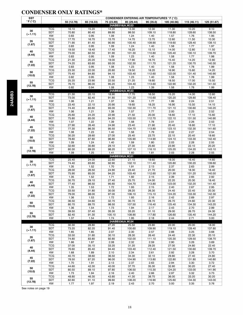
CONDENSER ONLY RATINGS*SST° F (° C)
CONDENSER ENTERING AIR TEMPERATURES ° F (° C)55 (12.78) 65 (18.33) 75 (23.89) 85 (29.44) 95 (35.0) 105 (40.56) 115 (46.11) 125 (51.67)
24ABB318(A,W)33
30(---1.11)
TCG 16.10 15.20 14.20 13.30 12.30 11.30 10.20 9.10SDT 70.80 80.40 89.90 99.50 109.10 118.80 128.60 138.50KW 0.83 0.95 1.09 1.24 1.40 1.57 1.76 1.95
35(1.67)
TCG 17.70 16.70 15.70 14.70 13.70 12.60 11.50 10.30SDT 71.90 81.40 90.90 100.40 109.90 119.60 129.40 139.10KW 0.83 0.95 1.09 1.24 1.40 1.58 1.77 1.97
40(4.44)
TCG 19.50 18.40 17.40 16.20 15.10 14.00 12.80 11.50SDT 73.00 82.50 91.90 101.30 110.80 120.40 130.10 139.70KW 0.83 0.95 1.09 1.23 1.40 1.58 1.77 1.98
45(7.22)
TCG 21.30 20.20 19.00 17.90 16.70 15.40 14.20 12.80SDT 74.20 83.60 93.00 102.30 111.70 121.20 130.70 140.30KW 0.83 0.95 1.08 1.23 1.40 1.58 1.78 1.99
50(10.0)
TCG 23.30 22.00 20.80 19.50 18.20 16.90 15.60 14.20SDT 75.40 84.80 94.10 103.40 112.60 122.00 131.40 140.90KW 0.82 0.95 1.08 1.23 1.40 1.58 1.78 1.99
55(12.78)
TCG 25.20 23.90 22.50 21.20 19.80 18.50 17.00 15.50SDT 76.70 86.00 95.20 104.40 113.60 122.90 132.20 141.50KW 0.82 0.94 1.08 1.23 1.39 1.58 1.78 1.99
24ABB324(A,W)33
30(---1.11)
TCG 21.30 20.10 18.90 17.70 16.50 15.20 14.00 12.60SDT 73.00 82.40 91.80 101.20 110.60 120.20 129.80 139.40KW 1.06 1.21 1.37 1.56 1.77 1.99 2.24 2.51
35(1.67)
TCG 23.40 22.10 20.90 19.60 18.20 16.90 15.50 14.10SDT 74.40 83.60 93.00 102.30 111.70 121.10 130.60 140.20KW 1.06 1.21 1.38 1.57 1.77 2.00 2.25 2.52
40(4.44)
TCG 25.60 24.20 22.90 21.50 20.00 18.60 17.10 15.60SDT 75.80 85.00 94.20 103.50 112.70 122.10 131.50 140.90KW 1.07 1.22 1.39 1.58 1.78 2.01 2.26 2.53
45(7.22)
TCG 27.90 26.40 24.90 23.40 21.90 20.40 18.80 17.10SDT 77.30 86.30 95.50 104.70 113.80 123.10 132.30 141.60KW 1.08 1.23 1.40 1.58 1.79 2.02 2.27 2.54
50(10.0)
TCG 30.20 28.60 27.00 25.40 23.70 22.10 20.40 18.60SDT 78.80 87.80 96.80 105.90 114.90 124.10 133.30 142.40KW 1.09 1.24 1.40 1.59 1.80 2.03 2.28 2.55
55(12.78)
TCG 32.60 30.80 29.10 27.30 25.60 23.90 22.10 20.20SDT 80.30 89.20 98.20 107.10 116.10 125.20 134.20 143.10KW 1.09 1.25 1.41 1.60 1.81 2.03 2.28 2.55
24ABB330(A,W)31
30(---1.11)
TCG 25.40 24.00 22.60 21.10 19.60 18.00 16.40 14.60SDT 74.40 83.60 92.90 102.10 111.40 120.80 130.20 139.60KW 1.35 1.52 1.70 1.91 2.13 2.37 2.63 2.89
35(1.67)
TCG 28.00 26.50 24.90 23.40 21.70 20.00 18.30 16.40SDT 75.90 85.00 94.20 103.40 112.60 121.90 131.20 140.50KW 1.35 1.52 1.71 1.92 2.15 2.39 2.65 2.92
40(4.44)
TCG 30.70 29.10 27.40 25.70 24.00 22.20 20.30 18.40SDT 77.40 86.50 95.60 104.70 113.80 123.00 132.20 141.40KW 1.35 1.53 1.72 1.93 2.15 2.40 2.67 2.95
45(7.22)
TCG 33.50 31.80 30.00 28.20 26.30 24.40 22.40 20.30SDT 79.00 88.00 97.00 106.10 115.10 124.20 133.30 142.30KW 1.36 1.53 1.72 1.93 2.16 2.42 2.69 2.97
50(10.0)
TCG 36.50 34.60 32.70 30.70 28.70 26.70 24.60 22.30SDT 80.70 89.70 98.50 107.50 116.40 125.40 134.30 143.20KW 1.36 1.54 1.73 1.94 2.17 2.43 2.70 2.99
55(12.78)
TCG 39.50 37.40 35.30 33.20 31.10 29.00 26.70 24.30SDT 82.40 91.30 100.10 108.90 117.80 126.60 135.40 144.20KW 1.37 1.54 1.74 1.95 2.18 2.44 2.71 3.00
24ABB336(A,W)34
30(---1.11)
TCG 30.30 28.80 27.20 25.50 23.80 22.00 20.00 18.00SDT 73.20 82.20 91.40 100.60 109.90 119.10 128.40 137.80KW 1.65 1.85 2.07 2.30 2.57 2.88 3.25 3.68
35(1.67)
TCG 33.50 31.80 30.10 28.30 26.40 24.40 22.30 20.10SDT 74.80 83.80 92.80 102.00 111.10 120.30 129.50 138.70KW 1.66 1.87 2.08 2.32 2.59 2.90 3.26 3.69
40(4.44)
TCG 37.00 35.10 33.20 31.20 29.20 27.00 24.80 22.40SDT 76.60 85.40 94.40 103.40 112.40 121.50 130.60 139.70KW 1.68 1.89 2.10 2.34 2.61 2.92 3.28 3.70
45(7.22)
TCG 40.70 38.60 36.50 34.30 32.10 29.80 27.40 24.80SDT 78.50 87.20 96.00 104.90 113.80 122.80 131.80 140.80KW 1.70 1.91 2.13 2.37 2.63 2.94 3.30 3.72
50(10.0)
TCG 44.60 42.30 40.00 37.70 35.30 32.80 30.20 27.40SDT 80.50 89.10 97.80 106.50 115.30 124.20 133.00 141.90KW 1.73 1.94 2.16 2.40 2.66 2.97 3.32 3.73
55(12.78)
TCG 48.80 46.30 43.80 41.30 38.70 36.00 33.20 30.20SDT 82.60 91.10 99.60 108.20 116.90 125.60 134.30 143.00KW 1.77 1.97 2.19 2.43 2.70 3.00 3.35 3.76
See notes on page 19
24ABB3
19
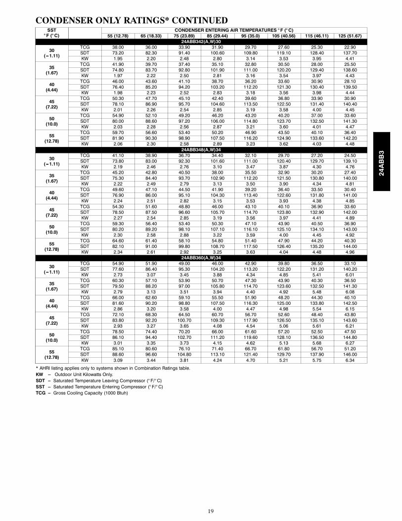
CONDENSER ONLY RATINGS* CONTINUEDSST° F (° C)
CONDENSER ENTERING AIR TEMPERATURES ° F (° C)55 (12.78) 65 (18.33) 75 (23.89) 85 (29.44) 95 (35.0) 105 (40.56) 115 (46.11) 125 (51.67)
24ABB342(A,W)30
30(---1.11)
TCG 38.00 36.00 33.90 31.90 29.70 27.60 25.30 22.90SDT 73.20 82.30 91.40 100.60 109.80 119.10 128.40 137.70KW 1.95 2.20 2.48 2.80 3.14 3.53 3.95 4.41
35(1.67)
TCG 41.90 39.70 37.40 35.10 32.80 30.50 28.00 25.50SDT 74.80 83.70 92.80 101.90 111.00 120.20 129.40 138.60KW 1.97 2.22 2.50 2.81 3.16 3.54 3.97 4.43
40(4.44)
TCG 46.00 43.60 41.10 38.70 36.20 33.60 30.90 28.10SDT 76.40 85.20 94.20 103.20 112.20 121.30 130.40 139.50KW 1.98 2.23 2.52 2.83 3.18 3.56 3.98 4.44
45(7.22)
TCG 50.30 47.70 45.10 42.40 39.60 36.80 33.90 30.90SDT 78.10 86.90 95.70 104.60 113.50 122.50 131.40 140.40KW 2.01 2.26 2.54 2.85 3.19 3.58 4.00 4.45
50(10.0)
TCG 54.90 52.10 49.20 46.20 43.20 40.20 37.00 33.60SDT 80.00 88.60 97.20 106.00 114.80 123.70 132.50 141.30KW 2.03 2.28 2.56 2.87 3.21 3.60 4.01 4.47
55(12.78)
TCG 59.70 56.60 53.40 50.20 46.90 43.50 40.10 36.40SDT 81.90 90.30 98.90 107.50 116.20 124.90 133.60 142.20KW 2.06 2.30 2.58 2.89 3.23 3.62 4.03 4.48
24ABB348(A,W)34
30(---1.11)
TCG 41.10 38.90 36.70 34.40 32.10 29.70 27.20 24.50SDT 73.80 83.00 92.30 101.60 111.00 120.40 129.70 139.10KW 2.19 2.46 2.76 3.10 3.47 3.87 4.30 4.76
35(1.67)
TCG 45.20 42.80 40.50 38.00 35.50 32.90 30.20 27.40SDT 75.30 84.40 93.70 102.90 112.20 121.50 130.80 140.00KW 2.22 2.49 2.79 3.13 3.50 3.90 4.34 4.81
40(4.44)
TCG 49.60 47.10 44.50 41.90 39.20 36.40 33.50 30.40SDT 76.90 86.00 95.10 104.30 113.40 122.60 131.80 141.00KW 2.24 2.51 2.82 3.15 3.53 3.93 4.38 4.85
45(7.22)
TCG 54.30 51.60 48.80 46.00 43.10 40.10 36.90 33.60SDT 78.50 87.50 96.60 105.70 114.70 123.80 132.90 142.00KW 2.27 2.54 2.85 3.19 3.56 3.97 4.41 4.89
50(10.0)
TCG 59.30 56.40 53.40 50.30 47.10 43.90 40.50 36.90SDT 80.20 89.20 98.10 107.10 116.10 125.10 134.10 143.00KW 2.30 2.58 2.88 3.22 3.59 4.00 4.45 4.92
55(12.78)
TCG 64.60 61.40 58.10 54.80 51.40 47.90 44.20 40.30SDT 82.10 91.00 99.80 108.70 117.50 126.40 135.20 144.00KW 2.34 2.61 2.92 3.25 3.63 4.04 4.48 4.96
24ABB360(A,W)34
30(---1.11)
TCG 54.90 51.90 49.00 46.00 42.90 39.80 36.50 33.10SDT 77.60 86.40 95.30 104.20 113.20 122.20 131.20 140.20KW 2.73 3.07 3.45 3.88 4.34 4.85 5.41 6.01
35(1.67)
TCG 60.30 57.10 53.90 50.70 47.30 43.90 40.30 36.50SDT 79.50 88.20 97.00 105.80 114.70 123.60 132.50 141.30KW 2.79 3.13 3.51 3.94 4.40 4.92 5.48 6.08
40(4.44)
TCG 66.00 62.60 59.10 55.50 51.90 48.20 44.30 40.10SDT 81.60 90.20 98.80 107.50 116.30 125.00 133.80 142.50KW 2.86 3.20 3.58 4.00 4.47 4.98 5.54 6.15
45(7.22)
TCG 72.10 68.30 64.50 60.70 56.70 52.60 48.40 43.80SDT 83.80 92.20 100.70 109.30 117.90 126.50 135.10 143.60KW 2.93 3.27 3.65 4.08 4.54 5.06 5.61 6.21
50(10.0)
TCG 78.50 74.40 70.20 66.00 61.60 57.20 52.50 47.50SDT 86.10 94.40 102.70 111.20 119.60 128.10 136.50 144.80KW 3.01 3.35 3.73 4.15 4.62 5.13 5.68 6.27
55(12.78)
TCG 85.10 80.60 76.10 71.40 66.70 61.80 56.70 51.20SDT 88.60 96.60 104.80 113.10 121.40 129.70 137.90 146.00KW 3.09 3.44 3.81 4.24 4.70 5.21 5.75 6.34
* AHRI listing applies only to systems shown in Combination Ratings table.KW --- Outdoor Unit Kilowatts Only.SDT --- Saturated Temperature Leaving Compressor (° F/° C)SST --- Saturated Temperature Entering Compressor (° F/° C)TCG --- Gross Cooling Capacity (1000 Btuh)
24ABB3
20
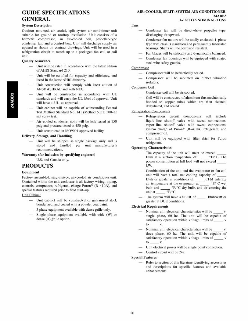
GUIDE SPECIFICATIONSGENERALSystem DescriptionOutdoor--mounted, air--cooled, split--system air conditioner unitsuitable for ground or rooftop installation. Unit consists of ahermetic compressor, an air--cooled coil, propeller--typecondenser fan, and a control box. Unit will discharge supply airupward as shown on contract drawings. Unit will be used in arefrigeration circuit to match up to a packaged fan coil or coilunit.
Quality Assurance— Unit will be rated in accordance with the latest edition
of AHRI Standard 210.
— Unit will be certified for capacity and efficiency, andlisted in the latest AHRI directory.
— Unit construction will comply with latest edition ofANSI/ ASHRAE and with NEC.
— Unit will be constructed in accordance with ULstandards and will carry the UL label of approval. Unitwill have c--UL--us approval.
— Unit cabinet will be capable of withstanding FederalTest Method Standard No. 141 (Method 6061) 500--hrsalt spray test.
— Air--cooled condenser coils will be leak tested at 150psig and pressure tested at 450 psig.
— Unit constructed in ISO9001 approved facility.
Delivery, Storage, and Handling— Unit will be shipped as single package only and is
stored and handled per unit manufacturer’srecommendations.
Warranty (for inclusion by specifying engineer)— U.S. and Canada only.
PRODUCTSEquipmentFactory assembled, single piece, air--cooled air conditioner unit.Contained within the unit enclosure is all factory wiring, piping,controls, compressor, refrigerant charge Puronr (R--410A), andspecial features required prior to field start--up.
Unit Cabinet
— Unit cabinet will be constructed of galvanized steel,bonderized, and coated with a powder coat paint.
— 3 phase equipment available with dense grille only.
— Single phase equipment available with wide (W) ordense (A) grille option.
AIR--COOLED, SPLIT--SYSTEM AIR CONDITIONER24ABB3
1--1/2 TO 5 NOMINAL TONSFans
— Condenser fan will be direct--drive propeller type,discharging air upward.
— Condenser fan motors will be totally enclosed, 1--phasetype with class B insulation and permanently lubricatedbearings. Shafts will be corrosion resistant.
— Fan blades will be statically and dynamically balanced.
— Condenser fan openings will be equipped with coatedsteel wire safety guards.
Compressor
— Compressor will be hermetically sealed.
— Compressor will be mounted on rubber vibrationisolators.
Condenser Coil
— Condenser coil will be air cooled.
— Coil will be constructed of aluminum fins mechanicallybonded to copper tubes which are then cleaned,dehydrated, and sealed.
Refrigeration Components
— Refrigeration circuit components will includeliquid--line shutoff valve with sweat connections,vapor--line shutoff valve with sweat connections,system charge of Puronr (R--410A) refrigerant, andcompressor oil.
— Unit will be equipped with filter drier for Puronrefrigerant.
Operating Characteristics— The capacity of the unit will meet or exceed _____
Btuh at a suction temperature of _____ _F/_C. Thepower consumption at full load will not exceed _____kW.
— Combination of the unit and the evaporator or fan coilunit will have a total net cooling capacity of _____Btuh or greater at conditions of _____ CFM enteringair temperature at the evaporator at _____ _F/_C wetbulb and _____ _F/_C dry bulb, and air entering theunit at _____ _F/_C.
— The system will have a SEER of _____ Btuh/watt orgreater at DOE conditions.
Electrical Requirements— Nominal unit electrical characteristics will be _____ v,
single phase, 60 hz. The unit will be capable ofsatisfactory operation within voltage limits of _____ vto _____ v.
— Nominal unit electrical characteristics will be _____ v,three phase, 60 hz. The unit will be capable ofsatisfactory operation within voltage limits of _____ vto _____ v.
— Unit electrical power will be single point connection.
— Control circuit will be 24v.
Special Features— Refer to section of this literature identifying accessories
and descriptions for specific features and availableenhancements.
24ABB3
21
SYSTEM DESIGN SUMMARY1. Intended for outdoor installation with free air inlet and outlet. Outdoor fan external static pressure available is less than 0.01--in. wc.
2. Minimum outdoor operating air temperature without low--ambient operation accessory is 55_F (12.8_C).
3. Maximum outdoor operating air temperature is 125_F (51.7_C).
4. For reliable operation, unit should be level in all horizontal planes.
5. For interconnecting refrigerant tube lengths greater than 80 ft (23.4 m) and/or 35 ft (10.7 m) vertical differential, consult ResidentialPiping and Longline Guideline and Service Manual available from equipment distributor.
6. If any refrigerant tubing is buried, provide a 6 in. (152.4 mm) vertical rise to the valve connections at the unit. Refrigerant tubinglengths up to 36 in. (914.4 mm) may be buried without further consideration. Do not bury refrigerant lines longer than 36 in. (914.4mm).
7. Use only copper wire for electric connection at unit. Aluminum and clad aluminum are not acceptable for the type of connectorprovided.
8. Do not apply capillary tube indoor coils to these units.
9. Factory--supplied filter drier must be installed.
24ABB3
22
Copyright 2013 Carrier Corp. S 7310 W. Morris St. S Indianapolis, IN 46231
Manufacturer reserves the right to change, at any time, specifications and designs without notice and without obligations.
Catalog No: 24ABB3---11PD
Replaces: 24ABB3---10PD
Edition Date: 07/13
24ABB3