Embed Size (px)
Citation preview

Product Data SheetPS-001885, Rev G
November 2017
Micro Motion® Model 5700 Transmitters withMVD™ Technology
Repeatable, reliable, accurate measurements
■ Faster processing speed delivers the best response even in the most challenging applications such asmeter proving, filling & dosing, and batching
■ Smart Meter Verification provides you with the confidence you need in your meter performance■ Zero verification confirms the calibration and indicates when it’s time to re-zero the meter■ Approved for custody transfer and certified for SIL2 and SIL3, which provides measurement confidence
and reliability
A window into your process
■ Easy access to detailed measurement history gives you valuable insight into your process for bettertroubleshooting and optimization
■ Real-time indication of multi-phase flow events allow for greater process control■ High-accuracy density measurement reduces or eliminates waste in your process while the embedded
historian records upsets and process deviations
Productivity through simplified solutions
■ Designed to minimize the time and expertise needed to install and operate the flowmeter■ Up to five fully configurable input/output channels that can be easily upgraded with changing needs■ Ethernet version includes multiple protocols on dual channels, plus a configurable I/O channel■ FOUNDATION™ Fieldbus version includes IEC-61158-2 FOUNDATION Fieldbus output, a fixed mA output
channel, and a configurable frequency / discrete output channel.■ Offline configuration and auditing through new file shuttling capability
Micro Motion Model 5700 transmittersModel 5700 transmitters deliver the best measurement technology and offer unparalleled support – ensuring total measurementconfidence, valuable process insight and greater operational efficiency. These transmitters provide the scalability, compatibility andperformance that your application demands.
Simplified installation and commissioning
An intuitive interface, spacious side-access wiring compartment and convenient mounting brackets.
Smart Meter Verification: advanced diagnostics for your entire system
Our online tool verifies that your meter performs as well as the day it was installed, giving you assurance in less than 90 seconds.
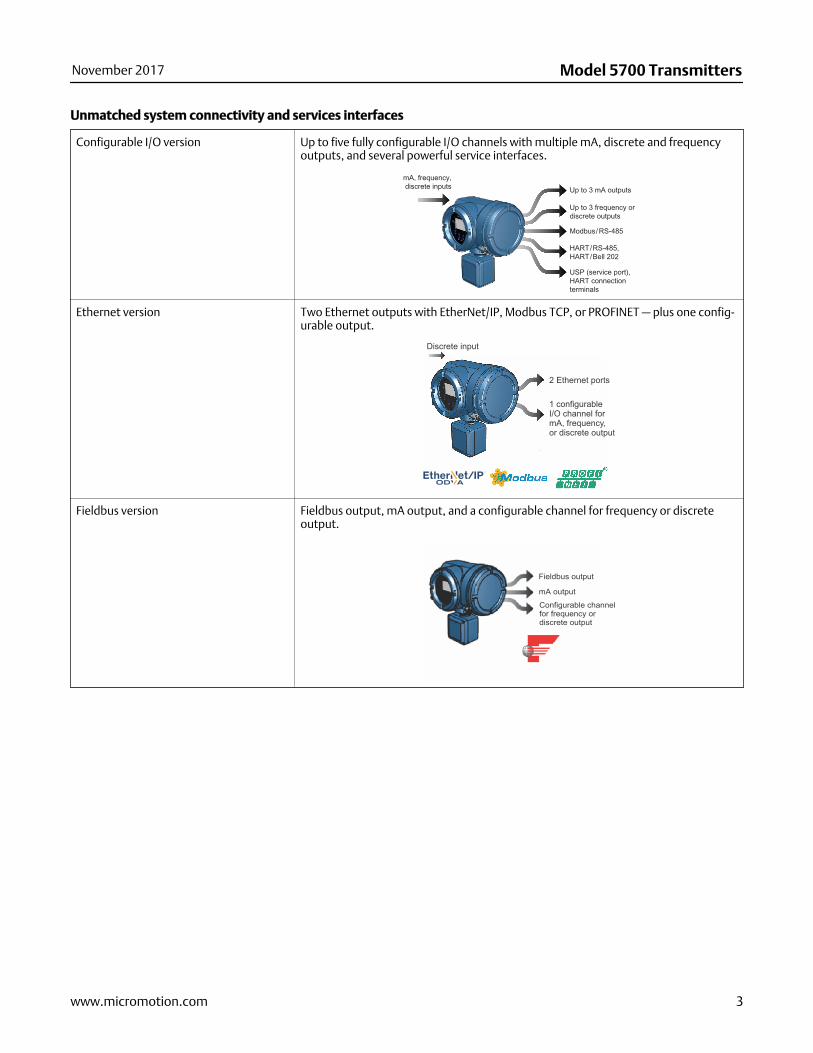
Measurement history for easier troubleshooting and optimization
Detailed history files deliver key time-stamped information about your process from configuration changes and alerts to processevents and statistics.
Model 5700 Transmitters November 2017
2 www.micromotion.com
Unmatched system connectivity and services interfaces
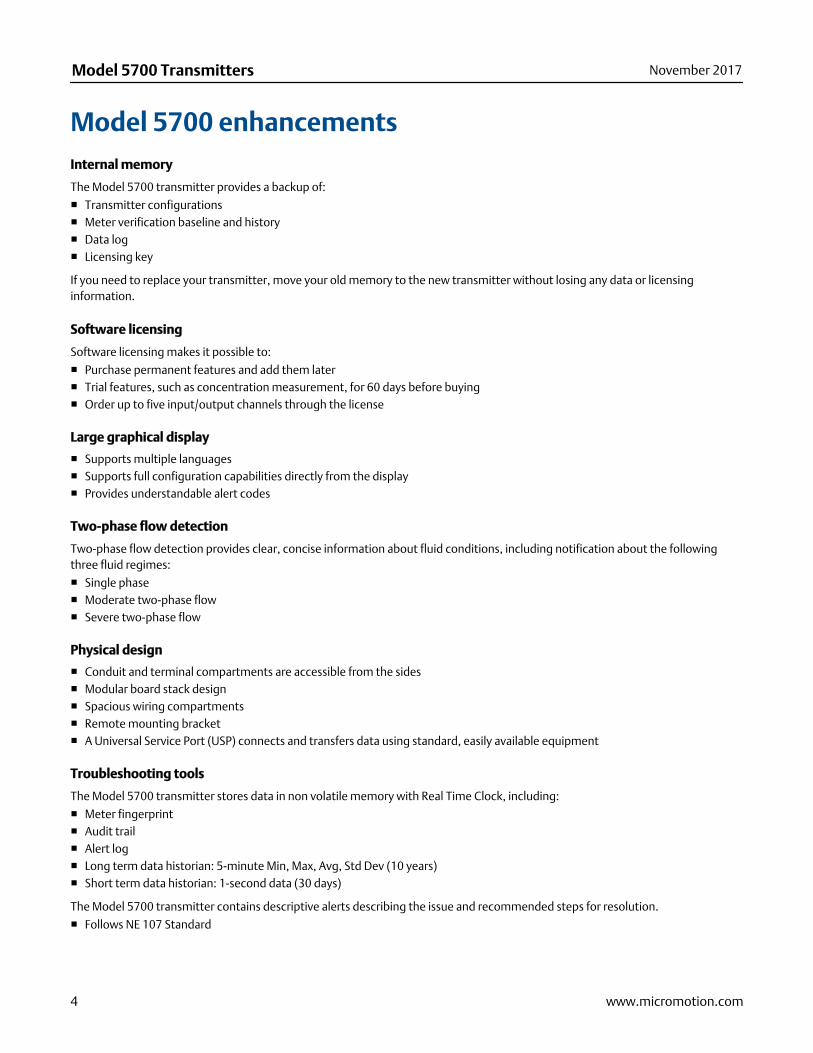
Configurable I/O version Up to five fully configurable I/O channels with multiple mA, discrete and frequencyoutputs, and several powerful service interfaces.
Ethernet version Two Ethernet outputs with EtherNet/IP, Modbus TCP, or PROFINET — plus one config-urable output.
Discrete input
2 Ethernet ports
1 configurableI/O channel formA, frequency,or discrete output
Fieldbus version Fieldbus output, mA output, and a configurable channel for frequency or discreteoutput.
Fieldbus output
mA output
Configurable channelfor frequency ordiscrete output
November 2017 Model 5700 Transmitters
www.micromotion.com 3
Model 5700 enhancementsInternal memory
The Model 5700 transmitter provides a backup of:
■ Transmitter configurations■ Meter verification baseline and history■ Data log■ Licensing key
If you need to replace your transmitter, move your old memory to the new transmitter without losing any data or licensinginformation.
Software licensing
Software licensing makes it possible to:
■ Purchase permanent features and add them later■ Trial features, such as concentration measurement, for 60 days before buying■ Order up to five input/output channels through the license
Large graphical display
■ Supports multiple languages■ Supports full configuration capabilities directly from the display■ Provides understandable alert codes
Two-phase flow detection
Two-phase flow detection provides clear, concise information about fluid conditions, including notification about the followingthree fluid regimes:
■ Single phase■ Moderate two-phase flow■ Severe two-phase flow
Physical design
■ Conduit and terminal compartments are accessible from the sides■ Modular board stack design■ Spacious wiring compartments■ Remote mounting bracket■ A Universal Service Port (USP) connects and transfers data using standard, easily available equipment
Troubleshooting tools
The Model 5700 transmitter stores data in non volatile memory with Real Time Clock, including:
■ Meter fingerprint■ Audit trail■ Alert log■ Long term data historian: 5-minute Min, Max, Avg, Std Dev (10 years)■ Short term data historian: 1-second data (30 days)
The Model 5700 transmitter contains descriptive alerts describing the issue and recommended steps for resolution.
■ Follows NE 107 Standard
Model 5700 Transmitters November 2017
4 www.micromotion.com
ApplicationsApplications are custom designed programs and software that offer additional functionality andperformance to transmitters. These applications are available through options in the transmitter modelcode, see the ordering information section for details.
Smart Meter Verification
Provides a quick, complete assessment of a Micro Motion Coriolis meter, determining whether the meterhas been affected by erosion, corrosion, or other influences affecting meter calibration. No secondaryreferences are required to perform this operation, and the meter can continue normal processmeasurement while the test is in progress.
Smart Meter Verification Professional on the Model 5700 transmitter also offers coating detection,installation verification, detection of optimal flow range, and two-phase flow detection. A 90-day trialversion is included with all Model 5700 transmitters with enhanced core processors. After the 90-day trial, abasic version of Smart Meter Verification will provide simple pass/fail results, and simple diagnostics thatrun without interrupting your processes.
Discrete batch control
■ Simple batch control based on totalizer values■ Frequency output configured as discrete output for transmitters with analog or intrinsically safe outputs■ Automatic overshoot compensation■ Single and dual stage batching available on the configurable I/O version when ordered with the Batching
Software (BS) package option■ Batch ticket printing available if Channel E is enabled (supports Terminal Window, Generic, Epson TM88v,
Epson TMU-295 and Digitec 6610A printers)
Note
Discrete batch control is not available with Model 5700 FOUNDATION Fieldbus models.
Petroleum measurement and API correction option
■ Accepts inputs from temperature and pressure devices■ Calculates values as per May, 2004 API Chapter 11.1
- Relative density (specific gravity and API gravity) at reference temperature from observed density andtemperature
- Volume corrected to reference temperature and pressure■ Calculates flow-weighted average temperature and flow-weighted average observed density (specific
gravity and API gravity)
November 2017 Model 5700 Transmitters
www.micromotion.com 5
Concentration measurement
Provides concentration measurement based on either industry-specific or liquid-specific units andrelationships. Standard measurement options include:■ Industry-specific:
- °Brix- °Plato- °Balling- °Baumé at SG60/60- Specific gravity
■ Liquid-specific:- %HFCS- Concentration derived from reference density- Concentration derived from specific gravity
Additionally, the application can be customized for site-specific concentration measurement (such as%HNO3, %NaOH).
Advanced Phase Measurement
■ Accurately measures liquid or gas flow in limited multiple-phase conditions- Immediate and continuous access to production or process data- Real time reporting of Gas Void Fraction (GVF)
■ Facilitates reliable measurement at a fraction of the cost of true multi-phase meters- Historian automatically captures all production data- Little to no maintenance or calibration
■ Combines with Net Oil Computer (NOC) or Concentration Measurement to measure two liquids in thepresence of gas- Provides single well real-time Net Oil and Net Water measurements- Improves Concentration Measurement in processes with intermittent entrained gas
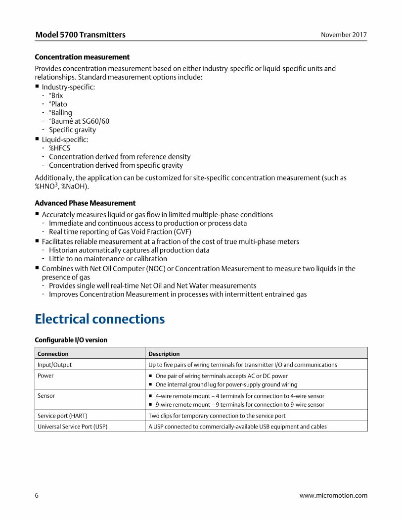
Electrical connectionsConfigurable I/O version
Connection Description
Input/Output Up to five pairs of wiring terminals for transmitter I/O and communications
Power ■ One pair of wiring terminals accepts AC or DC power■ One internal ground lug for power-supply ground wiring
Sensor ■ 4-wire remote mount – 4 terminals for connection to 4-wire sensor■ 9-wire remote mount – 9 terminals for connection to 9-wire sensor
Service port (HART) Two clips for temporary connection to the service port
Universal Service Port (USP) A USP connected to commercially-available USB equipment and cables
Model 5700 Transmitters November 2017
6 www.micromotion.com
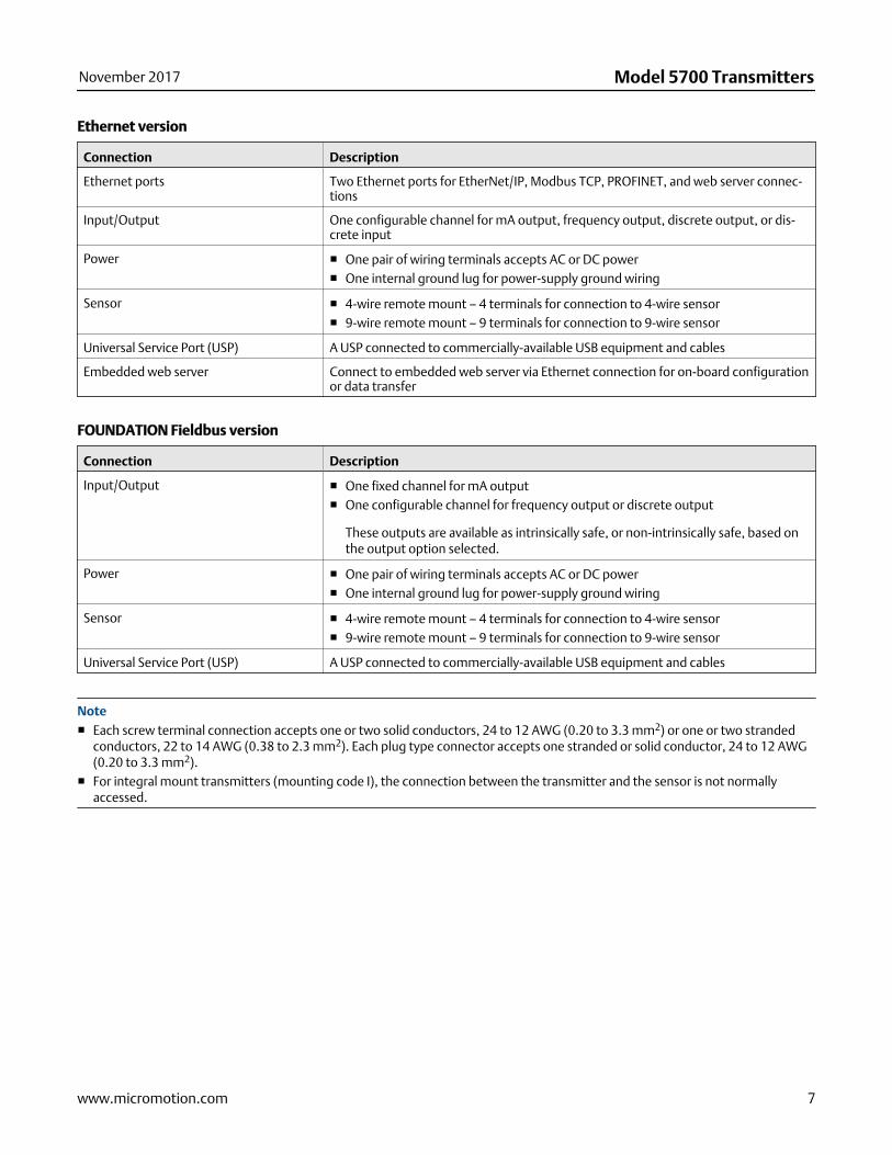
Ethernet version
Connection Description
Ethernet ports Two Ethernet ports for EtherNet/IP, Modbus TCP, PROFINET, and web server connec-tions
Input/Output One configurable channel for mA output, frequency output, discrete output, or dis-crete input
Power ■ One pair of wiring terminals accepts AC or DC power■ One internal ground lug for power-supply ground wiring
Sensor ■ 4-wire remote mount – 4 terminals for connection to 4-wire sensor■ 9-wire remote mount – 9 terminals for connection to 9-wire sensor
Universal Service Port (USP) A USP connected to commercially-available USB equipment and cables
Embedded web server Connect to embedded web server via Ethernet connection for on-board configurationor data transfer
FOUNDATION Fieldbus version
Connection Description
Input/Output ■ One fixed channel for mA output■ One configurable channel for frequency output or discrete output
These outputs are available as intrinsically safe, or non-intrinsically safe, based onthe output option selected.
Power ■ One pair of wiring terminals accepts AC or DC power■ One internal ground lug for power-supply ground wiring
Sensor ■ 4-wire remote mount – 4 terminals for connection to 4-wire sensor■ 9-wire remote mount – 9 terminals for connection to 9-wire sensor
Universal Service Port (USP) A USP connected to commercially-available USB equipment and cables
Note■ Each screw terminal connection accepts one or two solid conductors, 24 to 12 AWG (0.20 to 3.3 mm2) or one or two stranded
conductors, 22 to 14 AWG (0.38 to 2.3 mm2). Each plug type connector accepts one stranded or solid conductor, 24 to 12 AWG(0.20 to 3.3 mm2).
■ For integral mount transmitters (mounting code I), the connection between the transmitter and the sensor is not normallyaccessed.
November 2017 Model 5700 Transmitters
www.micromotion.com 7
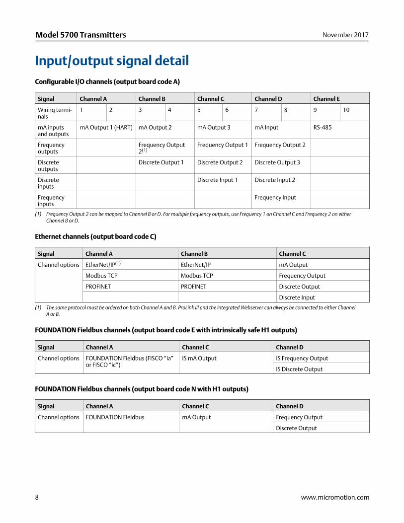
Input/output signal detailConfigurable I/O channels (output board code A)
Signal Channel A Channel B Channel C Channel D Channel E
Wiring termi-nals
1 2 3 4 5 6 7 8 9 10
mA inputsand outputs
mA Output 1 (HART) mA Output 2 mA Output 3 mA Input RS-485
Frequencyoutputs
Frequency Output2(1)
Frequency Output 1 Frequency Output 2
Discreteoutputs
Discrete Output 1 Discrete Output 2 Discrete Output 3
Discreteinputs
Discrete Input 1 Discrete Input 2
Frequencyinputs
Frequency Input
(1) Frequency Output 2 can be mapped to Channel B or D. For multiple frequency outputs, use Frequency 1 on Channel C and Frequency 2 on eitherChannel B or D.
Ethernet channels (output board code C)
Signal Channel A Channel B Channel C
Channel options EtherNet/IP(1) EtherNet/IP mA Output
Modbus TCP Modbus TCP Frequency Output
PROFINET PROFINET Discrete Output
Discrete Input
(1) The same protocol must be ordered on both Channel A and B. ProLink III and the Integrated Webserver can always be connected to either ChannelA or B.
FOUNDATION Fieldbus channels (output board code E with intrinsically safe H1 outputs)
Signal Channel A Channel C Channel D
Channel options FOUNDATION Fieldbus (FISCO “ia”or FISCO “ic”)
IS mA Output IS Frequency Output
IS Discrete Output
FOUNDATION Fieldbus channels (output board code N with H1 outputs)
Signal Channel A Channel C Channel D
Channel options FOUNDATION Fieldbus mA Output Frequency Output
Discrete Output
Model 5700 Transmitters November 2017
8 www.micromotion.com
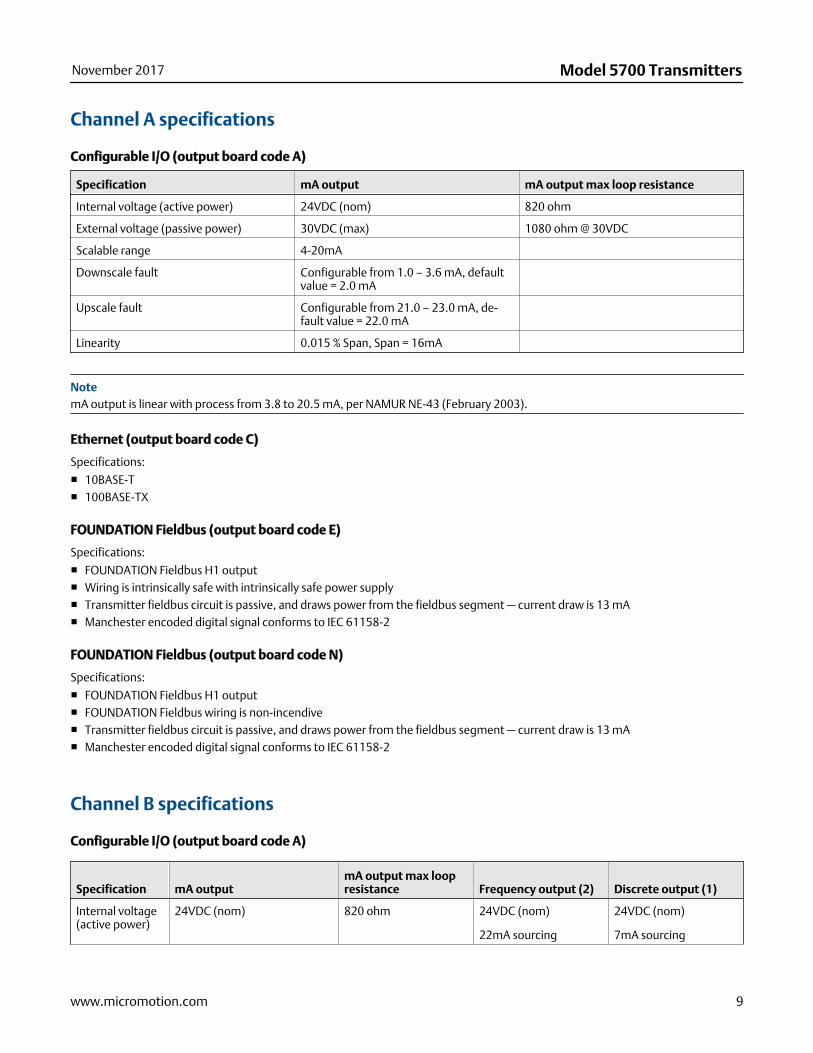
Channel A specifications
Configurable I/O (output board code A)
Specification mA output mA output max loop resistance
Internal voltage (active power) 24VDC (nom) 820 ohm
External voltage (passive power) 30VDC (max) 1080 ohm @ 30VDC
Scalable range 4-20mA
Downscale fault Configurable from 1.0 – 3.6 mA, defaultvalue = 2.0 mA
Upscale fault Configurable from 21.0 – 23.0 mA, de-fault value = 22.0 mA
Linearity 0.015 % Span, Span = 16mA
NotemA output is linear with process from 3.8 to 20.5 mA, per NAMUR NE-43 (February 2003).
Ethernet (output board code C)
Specifications:
■ 10BASE-T■ 100BASE-TX
FOUNDATION Fieldbus (output board code E)
Specifications:
■ FOUNDATION Fieldbus H1 output■ Wiring is intrinsically safe with intrinsically safe power supply■ Transmitter fieldbus circuit is passive, and draws power from the fieldbus segment — current draw is 13 mA■ Manchester encoded digital signal conforms to IEC 61158-2
FOUNDATION Fieldbus (output board code N)
Specifications:
■ FOUNDATION Fieldbus H1 output■ FOUNDATION Fieldbus wiring is non-incendive■ Transmitter fieldbus circuit is passive, and draws power from the fieldbus segment — current draw is 13 mA■ Manchester encoded digital signal conforms to IEC 61158-2
Channel B specifications
Configurable I/O (output board code A)
Specification mA outputmA output max loopresistance Frequency output (2) Discrete output (1)
Internal voltage(active power)
24VDC (nom) 820 ohm 24VDC (nom)
22mA sourcing
24VDC (nom)
7mA sourcing
November 2017 Model 5700 Transmitters
www.micromotion.com 9
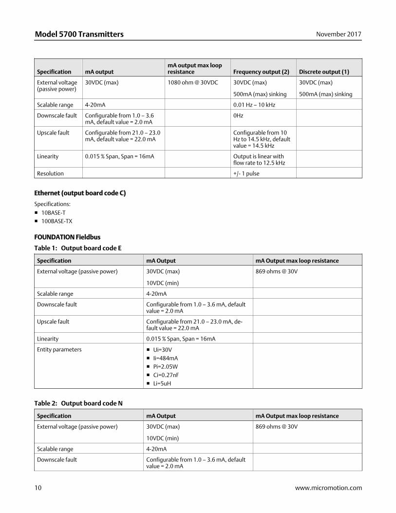
Specification mA outputmA output max loopresistance Frequency output (2) Discrete output (1)
External voltage(passive power)
30VDC (max) 1080 ohm @ 30VDC 30VDC (max)
500mA (max) sinking
30VDC (max)
500mA (max) sinking
Scalable range 4-20mA 0.01 Hz – 10 kHz
Downscale fault Configurable from 1.0 – 3.6mA, default value = 2.0 mA
0Hz
Upscale fault Configurable from 21.0 – 23.0mA, default value = 22.0 mA
Configurable from 10Hz to 14.5 kHz, defaultvalue = 14.5 kHz
Linearity 0.015 % Span, Span = 16mA Output is linear withflow rate to 12.5 kHz
Resolution +/- 1 pulse
Ethernet (output board code C)
Specifications:
■ 10BASE-T■ 100BASE-TX
FOUNDATION Fieldbus
Output board code ETable 1:
Specification mA Output mA Output max loop resistance
External voltage (passive power) 30VDC (max)
10VDC (min)
869 ohms @ 30V
Scalable range 4-20mA
Downscale fault Configurable from 1.0 – 3.6 mA, defaultvalue = 2.0 mA
Upscale fault Configurable from 21.0 – 23.0 mA, de-fault value = 22.0 mA
Linearity 0.015 % Span, Span = 16mA
Entity parameters ■ Ui=30V■ Ii=484mA■ Pi=2.05W■ Ci=0.27nF■ Li=5uH
Output board code NTable 2:
Specification mA Output mA Output max loop resistance
External voltage (passive power) 30VDC (max)
10VDC (min)
869 ohms @ 30V
Scalable range 4-20mA
Downscale fault Configurable from 1.0 – 3.6 mA, defaultvalue = 2.0 mA
Model 5700 Transmitters November 2017
10 www.micromotion.com
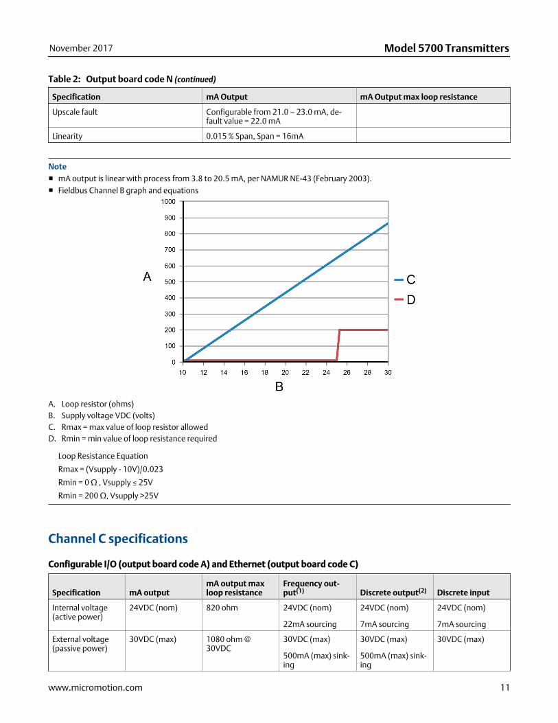
Output board code N (continued)Table 2:
Specification mA Output mA Output max loop resistance
Upscale fault Configurable from 21.0 – 23.0 mA, de-fault value = 22.0 mA
Linearity 0.015 % Span, Span = 16mA
Note■ mA output is linear with process from 3.8 to 20.5 mA, per NAMUR NE-43 (February 2003).■ Fieldbus Channel B graph and equations
A. Loop resistor (ohms)B. Supply voltage VDC (volts)C. Rmax = max value of loop resistor allowedD. Rmin = min value of loop resistance required
Loop Resistance Equation
Rmax = (Vsupply - 10V)/0.023
Rmin = 0 Ω , Vsupply ≤ 25V
Rmin = 200 Ω, Vsupply >25V
Channel C specifications
Configurable I/O (output board code A) and Ethernet (output board code C)
Specification mA outputmA output maxloop resistance
Frequency out-put(1) Discrete output(2) Discrete input
Internal voltage(active power)
24VDC (nom) 820 ohm 24VDC (nom)
22mA sourcing
24VDC (nom)
7mA sourcing
24VDC (nom)
7mA sourcing
External voltage(passive power)
30VDC (max) 1080 ohm @30VDC
30VDC (max)
500mA (max) sink-ing
30VDC (max)
500mA (max) sink-ing
30VDC (max)
November 2017 Model 5700 Transmitters
www.micromotion.com 11

Specification mA outputmA output maxloop resistance
Frequency out-put(1) Discrete output(2) Discrete input
Scalable range 4-20mA 0.01 Hz – 10 kHz
Downscale fault Configurable from1.0 – 3.6 mA, de-fault value = 2.0mA
0Hz
Upscale fault Configurable from21.0 – 23.0 mA, de-fault value = 22.0mA
Configurable from10 Hz to 14.5 kHz,default value =14.5 kHz
Resolution +/- 1 pulse
Linearity 0.015 % Span, Span= 16mA
Output is linearwith flow rate to12.5 kHz
Maximum positivethreshold
3VDC
Minimum negativethreshold
0.6VDC
(1) Load resistor (500 Ω resistance recommended for 24V supply.) Use the following equations for other load resistance values: Rmax = [(Vsupply -6V) / 0.003] - Rbarrier (maximum value of load resistor allowed) Rmin = 0 ohms
(2) Current = (Vsupply - 0.8V) / (1690 ohms + barrier internal resistance in ohms + load resistor in ohms)
NotemA output is linear with process from 3.8 to 20.5 mA, per NAMUR NE-43 (February 2003).
FOUNDATION Fieldbus (output code E)
Specification Frequency output(1) Discrete output(2)
External voltage (passive power) 30 VDC (max)
8 VDC(min)
30 VDC (max)
8 VDC (min)
Scalable range 0.01 Hz - 10 kHz
Downscale fault 0Hz
Upscale fault Configurable from 10 Hz to 14.5 kHz, de-fault value = 14.5 kHz
Resolution +/- 1 pulse
Entity parameters ■ Ui=30V■ Ii=484mA■ Pi=2.05W■ Ci=11.27nF■ Li =5uH
(1) Load resistor (500 Ω resistance recommended for 24V supply.) Use the following equations for other load resistance values: Rmax = [(Vsupply -6V) / 0.003] - Rbarrier (maximum value of load resistor allowed) Rmin = 0 ohms
(2) Current = (Vsupply - 0.8V) / (1690 ohms + barrier internal resistance in ohms + load resistor in ohms)
Model 5700 Transmitters November 2017
12 www.micromotion.com

FOUNDATION Fieldbus (output code N)
Specification Frequency output(1) Discrete output(2)
External voltage (passive power) 30 VDC (max)
8 VDC(min)(3)
30VDC (max)
8 VDC (min)(4)
Scalable range 0.01 Hz - 10 kHz
Downscale fault 0Hz
Upscale fault Configurable from 10 Hz to 14.5 kHz, de-fault value = 14.5 kHz
Resolution +/- 1 pulse
(1) Load resistor (500 Ω resistance recommended for 24V supply.) Use the following equations for other load resistance values: Rmax = [(Vsupply -6V) / 0.003] - Rbarrier (maximum value of load resistor allowed) Rmin = 0 ohms
(2) Current = (Vsupply - 0.8V) / (1690 ohms + barrier internal resistance in ohms + load resistor in ohms)
(3) Load resistor (500 Ω resistance recommended for 24V supply.) Use the following equations for other load resistance values: Rmax = [(Vsupply -6V) / 0.003] (maximum value of load resistor allowed) Rmin = 250 ohms (minimum value of load resistance required)
(4) Current = (Vsupply - 0.8V) / (1690 ohms + load resistor in ohms)
Channel D specificationsChannel D specifications do not apply to Ethernet or FOUNDATION Fieldbus implementations.
Configurable I/O (output board code A)
SpecificationFrequency output(2) mA input
Discrete output(3) Discrete input (2) Frequency input
Internal voltage(active power)
24VDC (nom)
2.21 kilo ohm pull-up resistor
24VDC (nom) 24VDC (nom)
2.21kilo ohm pull-up resistor
24VDC (nom)
2.21 kilo ohm pull-up resistor
24VDC (nom)
2.21 kilo ohm pull-up resistor
External voltage(passive power)
30VDC (max)
500mA (max) sink-ing
30VDC (max) 30VDC (max)
500mA (max) sink-ing
30VDC (max) 30VDC (max)
Scalable range 0.01 Hz – 10 kHz 4 - 20 mA
Fault indication ifmA input drops be-low 3.8 mA or goesabove 20.5 mA
Downscale fault 0Hz
Upscale fault Configurable from10 Hz to 14.5 kHz,default value =14.5 kHz
Accuracy +/- 1 pulse
Input resistance 100 ohm
Max frequency 100 Hz 3500 Hz
Maximum positivethreshold
3VDC 3VDC
November 2017 Model 5700 Transmitters
www.micromotion.com 13
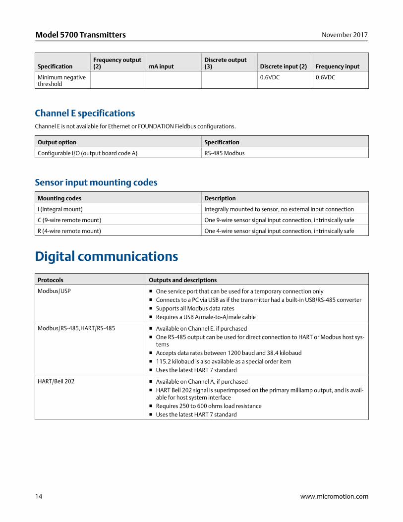
SpecificationFrequency output(2) mA input
Discrete output(3) Discrete input (2) Frequency input
Minimum negativethreshold
0.6VDC 0.6VDC
Channel E specificationsChannel E is not available for Ethernet or FOUNDATION Fieldbus configurations.
Output option Specification
Configurable I/O (output board code A) RS-485 Modbus
Sensor input mounting codes
Mounting codes Description
I (integral mount) Integrally mounted to sensor, no external input connection
C (9-wire remote mount) One 9-wire sensor signal input connection, intrinsically safe
R (4-wire remote mount) One 4-wire sensor signal input connection, intrinsically safe
Digital communications
Protocols Outputs and descriptions
Modbus/USP ■ One service port that can be used for a temporary connection only■ Connects to a PC via USB as if the transmitter had a built-in USB/RS-485 converter■ Supports all Modbus data rates■ Requires a USB A/male-to-A/male cable
Modbus/RS-485,HART/RS-485 ■ Available on Channel E, if purchased■ One RS-485 output can be used for direct connection to HART or Modbus host sys-
tems■ Accepts data rates between 1200 baud and 38.4 kilobaud■ 115.2 kilobaud is also available as a special order item■ Uses the latest HART 7 standard
HART/Bell 202 ■ Available on Channel A, if purchased■ HART Bell 202 signal is superimposed on the primary milliamp output, and is avail-
able for host system interface■ Requires 250 to 600 ohms load resistance■ Uses the latest HART 7 standard
Model 5700 Transmitters November 2017
14 www.micromotion.com
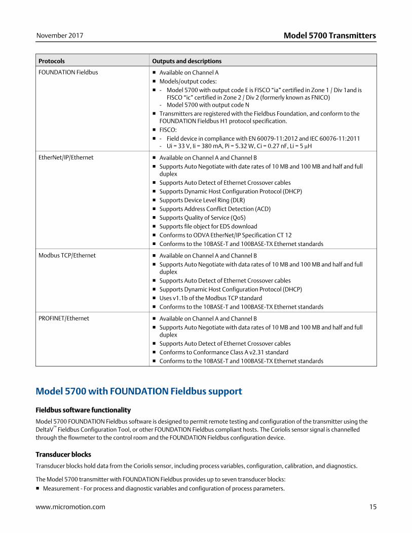
Protocols Outputs and descriptions
FOUNDATION Fieldbus ■ Available on Channel A■ Models/output codes:■ - Model 5700 with output code E is FISCO “ia” certified in Zone 1 / Div 1and is
FISCO “ic” certified in Zone 2 / Div 2 (formerly known as FNICO)- Model 5700 with output code N
■ Transmitters are registered with the Fieldbus Foundation, and conform to theFOUNDATION Fieldbus H1 protocol specification.
■ FISCO:■ - Field device in compliance with EN 60079-11:2012 and IEC 60076-11:2011
- Ui = 33 V, Ii = 380 mA, Pi = 5.32 W, Ci = 0.27 nF, Li = 5 µH
EtherNet/IP/Ethernet ■ Available on Channel A and Channel B■ Supports Auto Negotiate with date rates of 10 MB and 100 MB and half and full
duplex■ Supports Auto Detect of Ethernet Crossover cables■ Supports Dynamic Host Configuration Protocol (DHCP)■ Supports Device Level Ring (DLR)■ Supports Address Conflict Detection (ACD)■ Supports Quality of Service (QoS)■ Supports file object for EDS download■ Conforms to ODVA EtherNet/IP Specification CT 12■ Conforms to the 10BASE-T and 100BASE-TX Ethernet standards
Modbus TCP/Ethernet ■ Available on Channel A and Channel B■ Supports Auto Negotiate with data rates of 10 MB and 100 MB and half and full
duplex■ Supports Auto Detect of Ethernet Crossover cables■ Supports Dynamic Host Configuration Protocol (DHCP)■ Uses v1.1b of the Modbus TCP standard■ Conforms to the 10BASE-T and 100BASE-TX Ethernet standards
PROFINET/Ethernet ■ Available on Channel A and Channel B■ Supports Auto Negotiate with data rates of 10 MB and 100 MB and half and full
duplex■ Supports Auto Detect of Ethernet Crossover cables■ Conforms to Conformance Class A v2.31 standard■ Conforms to the 10BASE-T and 100BASE-TX Ethernet standards
Model 5700 with FOUNDATION Fieldbus support
Fieldbus software functionality
Model 5700 FOUNDATION Fieldbus software is designed to permit remote testing and configuration of the transmitter using theDeltaV™ Fieldbus Configuration Tool, or other FOUNDATION Fieldbus compliant hosts. The Coriolis sensor signal is channelledthrough the flowmeter to the control room and the FOUNDATION Fieldbus configuration device.
Transducer blocks
Transducer blocks hold data from the Coriolis sensor, including process variables, configuration, calibration, and diagnostics.
The Model 5700 transmitter with FOUNDATION Fieldbus provides up to seven transducer blocks:
■ Measurement - For process and diagnostic variables and configuration of process parameters.
November 2017 Model 5700 Transmitters
www.micromotion.com 15
■ Device - For device, display, channels configuration and device alert information■ Total inventory - For configuration of device totals and inventories■ Meter Verification - For Smart Meter Verification■ API referral - For petroleum measurement calculations using API MPMS Chapter 11.1
- For complex density and concentration calculations (e.g.,%HFCS, SG60/60)■ Concentration Measurement■ APM - For Advance Phase Measurement and NOC calculations
Resource block
The resource block contains physical device information, including available memory, manufacturer identification, type of device,and features.
Analog input function blocks
The Analog Input (AI) function block processes the measurement from the Coriolis sensor and makes it available to other functionblocks. It also allows filtering, alarm handling, and engineering unit changes. Each of the four Model 5700 AI blocks can be assignedto one of 27 available variables. There are four permanent Analog Input function blocks.
Analog output function blocks
The AO function block assigns an output value to a field device through a specified channel. The block supports mode control, signalstatus calculation, and simulation. The AO block can report pressure from an external pressure source, temperature from anexternal temperature source, or watercut from an external device. There are two permanent Analog Output function blocks.
Discrete input function block
One permanent Discrete Input (DI) function block can be assigned to any of the Discrete Input variable channels in the transducerblock. The DI block channels are: forward/reverse indication, zero in progress, fault condition indication, and meter verificationfailure.
Discrete output function block
One permanent Discrete Output (DO) function block can be assigned to any of the Discrete Output variable channels in thetransducer block. The DO block channels are: Start Sensor Zero, Increment CM Curve, Start Meter Verification in ContinuousMeasurement Mode, Reset All Process Totals, Start/Stop All Totals, Reset Config Totals 1-7.
Proportional integral derivative function block
One permanent Proportional Integral Derivative (PID) function block combines all the necessary logic to perform proportional/integral/derivative control. The block supports mode control, signal scaling and limiting, feed forward control, override tracking,alarm limit detection, and signal status propagation.
Integrator function block
Two permanent Integrator (INT) function blocks provides functionality for the transmitter totalizers. Any of seven internal totals orany of seven internal inventories can be selected and reset.
Diagnostics and service
Model 5700 transmitters automatically perform continuous self diagnostics. Using the Device transducer block, the user canperform on-line testing of the transmitter and sensor. Diagnostics are event driven and do not require polling for access.
PlantWeb® Field Diagnostic is supported. The diagnostic information is based on NAMUR NE 107 standard.
Model 5700 Transmitters November 2017
16 www.micromotion.com
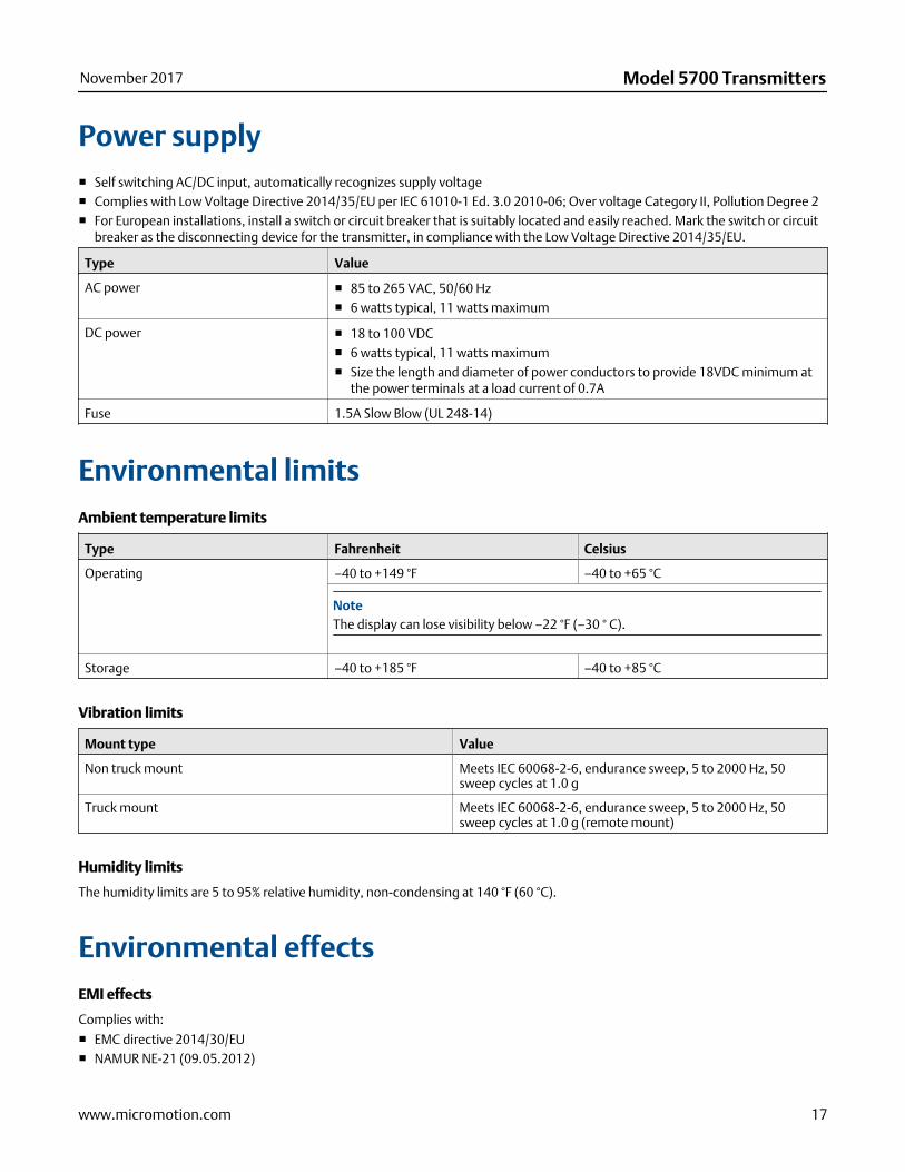
Power supply■ Self switching AC/DC input, automatically recognizes supply voltage■ Complies with Low Voltage Directive 2014/35/EU per IEC 61010-1 Ed. 3.0 2010-06; Over voltage Category II, Pollution Degree 2■ For European installations, install a switch or circuit breaker that is suitably located and easily reached. Mark the switch or circuit
breaker as the disconnecting device for the transmitter, in compliance with the Low Voltage Directive 2014/35/EU.
Type Value
AC power ■ 85 to 265 VAC, 50/60 Hz■ 6 watts typical, 11 watts maximum
DC power ■ 18 to 100 VDC■ 6 watts typical, 11 watts maximum■ Size the length and diameter of power conductors to provide 18VDC minimum at
the power terminals at a load current of 0.7A
Fuse 1.5A Slow Blow (UL 248-14)
Environmental limitsAmbient temperature limits
Type Fahrenheit Celsius
Operating –40 to +149 °F –40 to +65 °C
NoteThe display can lose visibility below –22 °F (–30 ° C).
Storage –40 to +185 °F –40 to +85 °C
Vibration limits
Mount type Value
Non truck mount Meets IEC 60068-2-6, endurance sweep, 5 to 2000 Hz, 50sweep cycles at 1.0 g
Truck mount Meets IEC 60068-2-6, endurance sweep, 5 to 2000 Hz, 50sweep cycles at 1.0 g (remote mount)
Humidity limits
The humidity limits are 5 to 95% relative humidity, non-condensing at 140 °F (60 °C).
Environmental effectsEMI effects
Complies with:
■ EMC directive 2014/30/EU■ NAMUR NE-21 (09.05.2012)
November 2017 Model 5700 Transmitters
www.micromotion.com 17
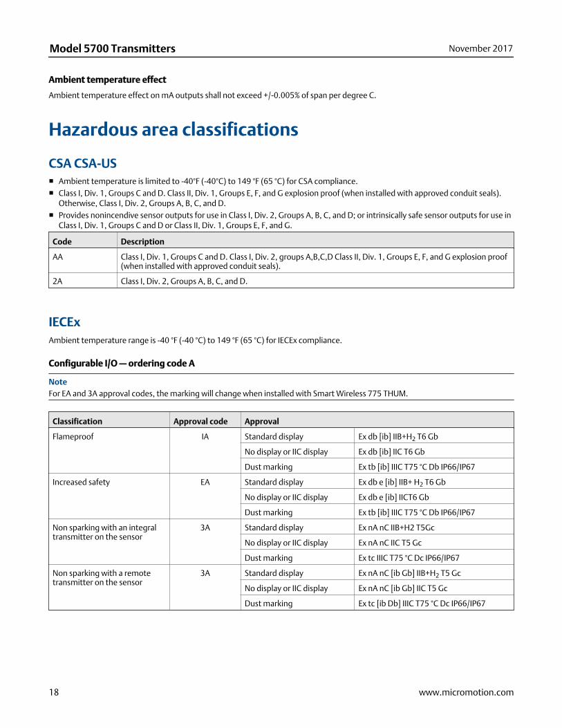
Ambient temperature effect
Ambient temperature effect on mA outputs shall not exceed +/-0.005% of span per degree C.
Hazardous area classifications
CSA CSA-US■ Ambient temperature is limited to -40°F (-40°C) to 149 °F (65 °C) for CSA compliance.■ Class I, Div. 1, Groups C and D. Class II, Div. 1, Groups E, F, and G explosion proof (when installed with approved conduit seals).
Otherwise, Class I, Div. 2, Groups A, B, C, and D.■ Provides nonincendive sensor outputs for use in Class I, Div. 2, Groups A, B, C, and D; or intrinsically safe sensor outputs for use in
Class I, Div. 1, Groups C and D or Class II, Div. 1, Groups E, F, and G.
Code Description
AA Class I, Div. 1, Groups C and D. Class I, Div. 2, groups A,B,C,D Class II, Div. 1, Groups E, F, and G explosion proof(when installed with approved conduit seals).
2A Class I, Div. 2, Groups A, B, C, and D.
IECExAmbient temperature range is -40 °F (-40 °C) to 149 °F (65 °C) for IECEx compliance.
Configurable I/O — ordering code A
NoteFor EA and 3A approval codes, the marking will change when installed with Smart Wireless 775 THUM.
Classification Approval code Approval
Flameproof IA Standard display Ex db [ib] IIB+H2 T6 Gb
No display or IIC display Ex db [ib] IIC T6 Gb
Dust marking Ex tb [ib] IIIC T75 °C Db IP66/IP67
Increased safety EA Standard display Ex db e [ib] IIB+ H2 T6 Gb
No display or IIC display Ex db e [ib] IICT6 Gb
Dust marking Ex tb [ib] IIIC T75 °C Db IP66/IP67
Non sparking with an integraltransmitter on the sensor
3A Standard display Ex nA nC IIB+H2 T5Gc
No display or IIC display Ex nA nC IIC T5 Gc
Dust marking Ex tc IIIC T75 °C Dc IP66/IP67
Non sparking with a remotetransmitter on the sensor
3A Standard display Ex nA nC [ib Gb] IIB+H2 T5 Gc
No display or IIC display Ex nA nC [ib Gb] IIC T5 Gc
Dust marking Ex tc [ib Db] IIIC T75 °C Dc IP66/IP67
Model 5700 Transmitters November 2017
18 www.micromotion.com

Ethernet — ordering code C
Classification Approval code Approval
Flameproof IA Standard display Ex db [ib] IIB+H2 T6 Gb
No display or IIC display Ex db [ib] IIC T6 Gb
Dust marking Ex tb [ib] IIIC T75 °C Db IP66/IP67
Non sparking with an integraltransmitter on the sensor
3A Standard display Ex nA nC IIB+H2 T4 Gc
No display or IIC display Ex nA nC IIC T4 Gc
Dust marking Ex tc IIIC T75 °C Dc IP66/IP67
Non sparking with a remotetransmitter on the sensor
3A Standard display Ex nA nC [ib Gb] IIB+H2 T4 Gc
No display or IIC display Ex nA nC [ibGb] IIC T4 Gc
Dust marking Ex tc [ib Db] IIIC T75 °C Dc IP66/IP67
FOUNDATION Fieldbus — ordering code N
Classification Approval code Approval
Flameproof IA Standard display Ex db [ib] IIB+H2 T6 Gb
No display or IIC display Ex db [ib] IIC T6 Gb
Dust marking Ex tb [ib] IIIC T75 °C Db IP66/IP67
Increased safety EA Standard display Ex db e [ib] IIB+ H2 T6 Gb
No display or IIC display Ex db e [ib] IICT6 Gb
Dust marking Ex tb [ib] IIIC T75 °C Db IP66/IP67
Non sparking with an integraltransmitter on the sensor
3A Standard display Ex nA IIB+H2 T4 Gc
No display or IIC display Ex nA IIC T4 Gc
Dust marking Ex tc IIIC T75 °C Dc IP66/IP67
Non sparking with a remotetransmitter on the sensor
3A Standard display Ex nA [ib Gb] IIB + H2 T4 Gc
No display or IIC display Ex nA [ib Gb] IIC T4 Gc
Dust marking Ex tc [ib Db] IIIC T75 °C Dc IP66/IP67
FOUNDATION Fieldbus FISCO — ordering code E
FISCO covers Ex ia, ib, and ic.
Classification Approval code Approval
Flameproof IA Standard display Ex db [ia Ga] [ib] IIB+H2 T6 Gb
No display or IIC display Ex db [ia Ga][ib] IIC T6 Gb
Dust marking Ex tb [ia Da] [ib] IIIC T75 °C Db IP66/IP67
Increased safety EA Standard display Ex db e [ia Ga][ib] IIB+H2 T6 Gb
No display or IIC display Ex db e [ia Ga] [ib] IICT6 Gb
Dust marking Ex tb [ia Da] [ib] IIIC T75 °C Db IP66/IP67
Non sparking with an inte-gral transmitter on the sen-sor
3A Standard display Ex nA [ic] IIB+H2 T4 Gc
No display or IIC display Ex nA [ic] IIC T4 Gc
Dust marking Ex tc IIIC T75 °C Dc IP66/IP67
November 2017 Model 5700 Transmitters
www.micromotion.com 19
Classification Approval code Approval
Non sparking with a remotetransmitter on the sensor
3A Standard display Ex nA [ic] [ib Gb] IIB+H2 T4 Gc
No display or IIC display Ex nA [ic] [ib Gb] IIC T4 Gc
Dust marking Ex tc [ib Db] IIIC T75 °C Dc IP66/IP67
Code Description
IA all mounting options Used in IECEx EPL Gb/Db Zone 1/21 with flameproof (Ex db) terminal compartment with[ib] output for sensors installed in Zone 1/21
EA all mounting options Used in IECEx EPL Gb/Db Zone 1/21 with increased safety (Ex e) terminal compartment andflame proof (Ex db) electronic compartment with [ib] output for sensors installed in Zone1/21
3A mounting option I Used in IECEx EPL Gc/Dc Zone 2/22, non sparking
3A mounting option R and C Used in IECEx EPL Gc/Dc Zone 2/22, non sparking with [ib Gb/Db] output for sensors instal-led in Zone 1/21
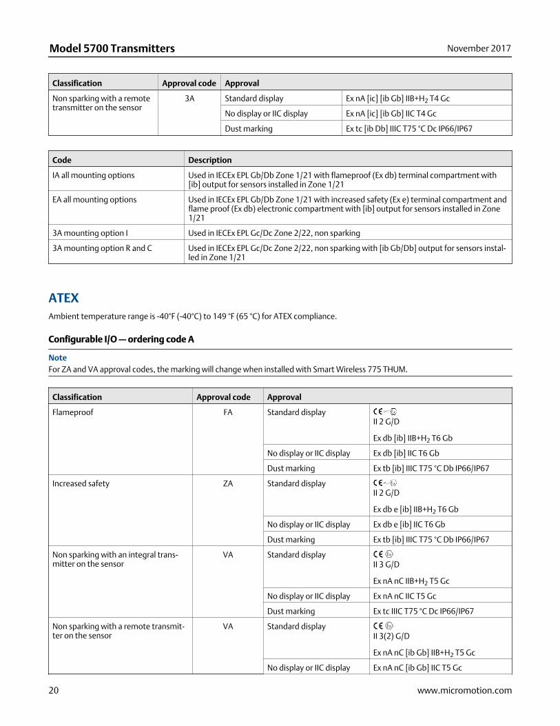
ATEXAmbient temperature range is -40°F (-40°C) to 149 °F (65 °C) for ATEX compliance.
Configurable I/O — ordering code A
NoteFor ZA and VA approval codes, the marking will change when installed with Smart Wireless 775 THUM.
Classification Approval code Approval
Flameproof FA Standard displayII 2 G/D
Ex db [ib] IIB+H2 T6 Gb
No display or IIC display Ex db [ib] IIC T6 Gb
Dust marking Ex tb [ib] IIIC T75 °C Db IP66/IP67
Increased safety ZA Standard displayII 2 G/D
Ex db e [ib] IIB+H2 T6 Gb
No display or IIC display Ex db e [ib] IIC T6 Gb
Dust marking Ex tb [ib] IIIC T75 °C Db IP66/IP67
Non sparking with an integral trans-mitter on the sensor
VA Standard displayII 3 G/D
Ex nA nC IIB+H2 T5 Gc
No display or IIC display Ex nA nC IIC T5 Gc
Dust marking Ex tc IIIC T75 °C Dc IP66/IP67
Non sparking with a remote transmit-ter on the sensor
VA Standard displayII 3(2) G/D
Ex nA nC [ib Gb] IIB+H2 T5 Gc
No display or IIC display Ex nA nC [ib Gb] IIC T5 Gc
Model 5700 Transmitters November 2017
20 www.micromotion.com
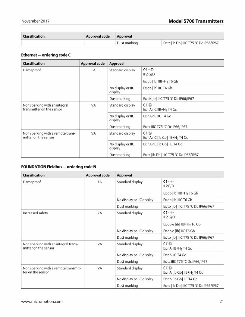
Classification Approval code Approval
Dust marking Ex tc [ib Db] IIIC T75 °C Dc IP66/IP67
Ethernet — ordering code C
Classification Approval code Approval
Flameproof FA Standard displayII 2 G/D
Ex db [ib] IIB+H2 T6 Gb
No display or IICdisplay
Ex db [ib] IIC T6 Gb
Dust marking Ex tb [ib] IIIC T75 °C Db IP66/IP67
Non sparking with an integraltransmitter on the sensor
VA Standard displayEx nA nC IIB+H2 T4 Gc
No display or IICdisplay
Ex nA nC IIC T4 Gc
Dust marking Ex tc IIIC T75 °C Dc IP66/IP67
Non sparking with a remote trans-mitter on the sensor
VA Standard displayEx nA nC [ib Gb] IIB+H2 T4 Gc
No display or IICdisplay
Ex nA nC [ib Gb] IIC T4 Gc
Dust marking Ex tc [ib Db] IIIC T75 °C Dc IP66/IP67
FOUNDATION Fieldbus — ordering code N
Classification Approval code Approval
Flameproof FA Standard displayII 2G/D
Ex db [ib] IIB+H2 T6 Gb
No display or IIC display Ex db [ib] IIC T6 Gb
Dust marking Ex tb [ib] IIIC T75 °C Db IP66/IP67
Increased safety ZA Standard displayII 2 G/D
Ex db e [ib] IIB+H2 T6 Gb
No display or IIC display Ex db e [ib] IIC T6 Gb
Dust marking Ex tb [ib] IIIC T75 °C Db IP66/IP67
Non sparking with an integral trans-mitter on the sensor
VA Standard displayEx nA IIB+H2 T4 Gc
No display or IIC display Ex nA IIC T4 Gc
Dust marking Ex tc IIIC T75 °C Dc IP66/IP67
Non sparking with a remote transmit-ter on the sensor
VA Standard displayEx nA [ib Gb] IIB+H2 T4 Gc
No display or IIC display Ex nA [ib Gb] IIC T4 Gc
Dust marking Ex tc [ib Db] IIIC T75 °C Dc IP66/IP67
November 2017 Model 5700 Transmitters
www.micromotion.com 21
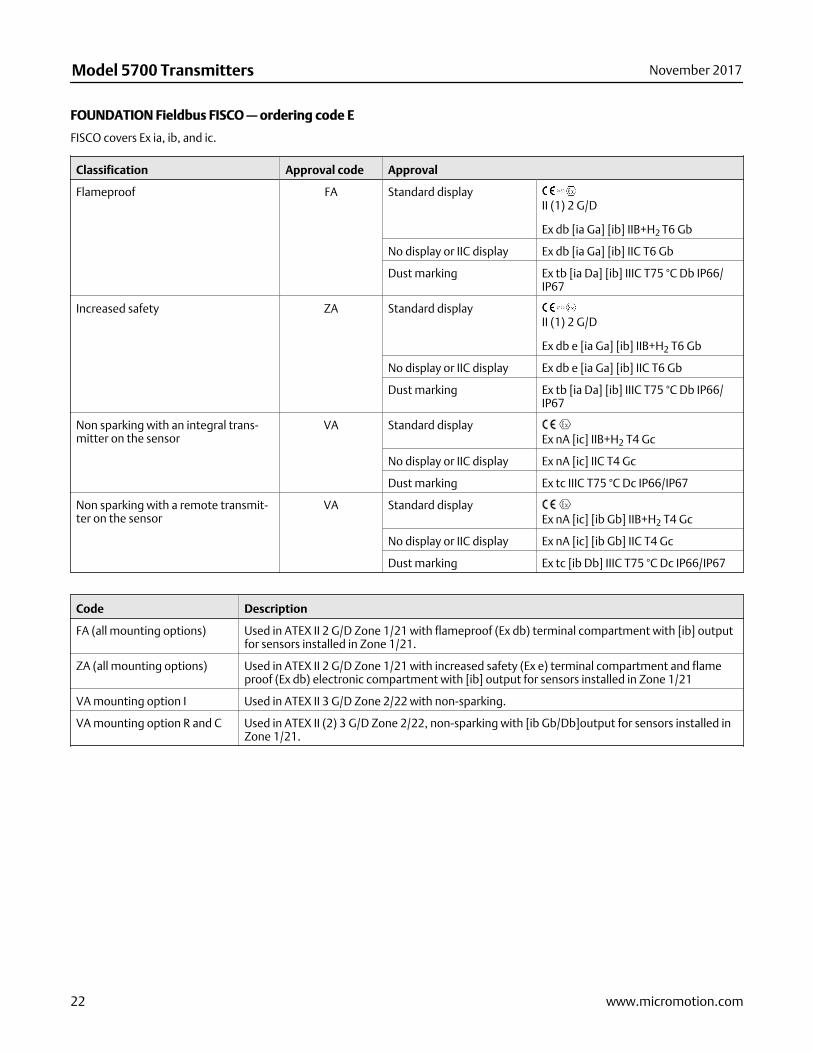
FOUNDATION Fieldbus FISCO — ordering code E
FISCO covers Ex ia, ib, and ic.
Classification Approval code Approval
Flameproof FA Standard displayII (1) 2 G/D
Ex db [ia Ga] [ib] IIB+H2 T6 Gb
No display or IIC display Ex db [ia Ga] [ib] IIC T6 Gb
Dust marking Ex tb [ia Da] [ib] IIIC T75 °C Db IP66/IP67
Increased safety ZA Standard displayII (1) 2 G/D
Ex db e [ia Ga] [ib] IIB+H2 T6 Gb
No display or IIC display Ex db e [ia Ga] [ib] IIC T6 Gb
Dust marking Ex tb [ia Da] [ib] IIIC T75 °C Db IP66/IP67
Non sparking with an integral trans-mitter on the sensor
VA Standard displayEx nA [ic] IIB+H2 T4 Gc
No display or IIC display Ex nA [ic] IIC T4 Gc
Dust marking Ex tc IIIC T75 °C Dc IP66/IP67
Non sparking with a remote transmit-ter on the sensor
VA Standard displayEx nA [ic] [ib Gb] IIB+H2 T4 Gc
No display or IIC display Ex nA [ic] [ib Gb] IIC T4 Gc
Dust marking Ex tc [ib Db] IIIC T75 °C Dc IP66/IP67
Code Description
FA (all mounting options) Used in ATEX II 2 G/D Zone 1/21 with flameproof (Ex db) terminal compartment with [ib] outputfor sensors installed in Zone 1/21.
ZA (all mounting options) Used in ATEX II 2 G/D Zone 1/21 with increased safety (Ex e) terminal compartment and flameproof (Ex db) electronic compartment with [ib] output for sensors installed in Zone 1/21
VA mounting option I Used in ATEX II 3 G/D Zone 2/22 with non-sparking.
VA mounting option R and C Used in ATEX II (2) 3 G/D Zone 2/22, non-sparking with [ib Gb/Db]output for sensors installed inZone 1/21.
Model 5700 Transmitters November 2017
22 www.micromotion.com
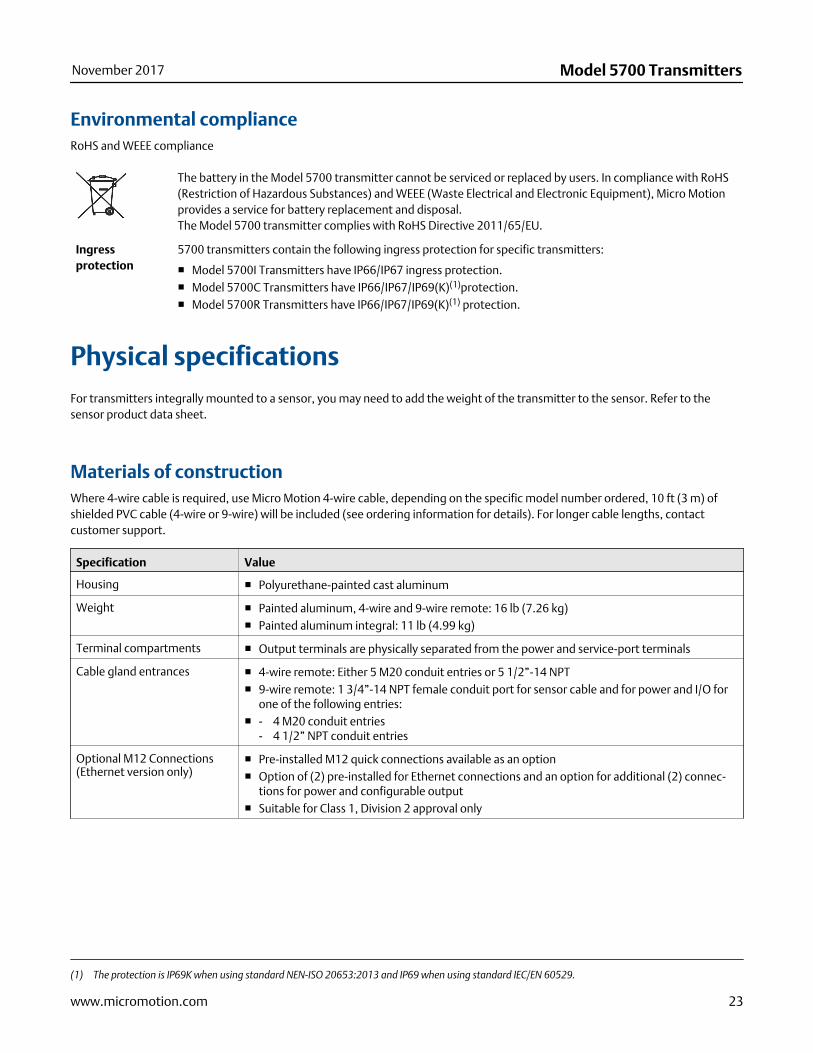
Environmental complianceRoHS and WEEE compliance
The battery in the Model 5700 transmitter cannot be serviced or replaced by users. In compliance with RoHS(Restriction of Hazardous Substances) and WEEE (Waste Electrical and Electronic Equipment), Micro Motionprovides a service for battery replacement and disposal.The Model 5700 transmitter complies with RoHS Directive 2011/65/EU.
Ingressprotection
5700 transmitters contain the following ingress protection for specific transmitters:
■ Model 5700I Transmitters have IP66/IP67 ingress protection.■ Model 5700C Transmitters have IP66/IP67/IP69(K)(1)protection.■ Model 5700R Transmitters have IP66/IP67/IP69(K)(1) protection.
Physical specificationsFor transmitters integrally mounted to a sensor, you may need to add the weight of the transmitter to the sensor. Refer to thesensor product data sheet.
Materials of constructionWhere 4-wire cable is required, use Micro Motion 4-wire cable, depending on the specific model number ordered, 10 ft (3 m) ofshielded PVC cable (4-wire or 9-wire) will be included (see ordering information for details). For longer cable lengths, contactcustomer support.
Specification Value
Housing ■ Polyurethane-painted cast aluminum
Weight ■ Painted aluminum, 4-wire and 9-wire remote: 16 lb (7.26 kg)■ Painted aluminum integral: 11 lb (4.99 kg)
Terminal compartments ■ Output terminals are physically separated from the power and service-port terminals
Cable gland entrances ■ 4-wire remote: Either 5 M20 conduit entries or 5 1/2”-14 NPT■ 9-wire remote: 1 3/4”-14 NPT female conduit port for sensor cable and for power and I/O for
one of the following entries:■ - 4 M20 conduit entries
- 4 1/2” NPT conduit entries
Optional M12 Connections(Ethernet version only)
■ Pre-installed M12 quick connections available as an option■ Option of (2) pre-installed for Ethernet connections and an option for additional (2) connec-
tions for power and configurable output■ Suitable for Class 1, Division 2 approval only
(1) The protection is IP69K when using standard NEN-ISO 20653:2013 and IP69 when using standard IEC/EN 60529.
November 2017 Model 5700 Transmitters
www.micromotion.com 23

Specification Value
Mounting ■ Integral or remote mounting options■ May be remotely connected to any 4-wire or 9-wire Micro Motion sensor■ Remote-mount transmitters include a 304L and a 316L stainless steel mounting bracket, and
the hardware for installing the transmitter on the mounting bracket■ For remote 4-wire or 9-wire mounts, the transmitter can be rotated 360 degrees with respect
to customer wall or pipe in 90-degree increments■ For integral mount, the transmitter can be rotated with respect to the sensor in 45-degree
increments
Maximum cable lengths be-tween sensor and transmitter
Cable type Wire gauge Maximum length
Micro Motion 9-wire Not applicable 1000 feet (300 meters)(1)
Micro Motion 4-wire Not applicable 1000 feet (300 meters)
User-supplied 4-wire VDC 22 AWG (0.34 mm2) 300 feet (90 meters)
VDC 20 AWG (0.5 mm2) 500 feet (150 meters)
VDC 18 AWG (0.8 mm2) 1000 feet (300 meters)
RS-485 22 AWG (0.34 mm2)or larger
1000 feet (300 meters)
For the cable sizing formula, see the appropriate Micro Motion Model 5700 installation manual.
Standard interface/display ■ Graphical backlit display with 4-button optical controls and flowmeter-status LED■ Depending on purchase option, transmitter housing cover has either a non-glass lens or tem-
pered glass lens option■ To facilitate various mounting orientations, the display can be rotated on transmitter, 360 de-
grees, in 90-degree increments■ Display supports English, German, French, Spanish, Portuguese, Russian, Chinese, and Japa-
nese
Display functions ■ Complete operation and configuration through the display, no service tool required■ View process variables■ Start, stop, and reset totalizers■ View and acknowledge alarms■ View the Smart Meter Verification initiation and results from the display without interrupting
process measurement■ Set the flowmeter to zero, simulate outputs, change measurement units, configure outputs,
and set RS-485 communications options■ View a three-color LED status light on display panel that indicates flowmeter conditions at a
glance
(1) For Smart Meter Verification, the limit is 66 feet (20 meters)
Model 5700 Transmitters November 2017
24 www.micromotion.com
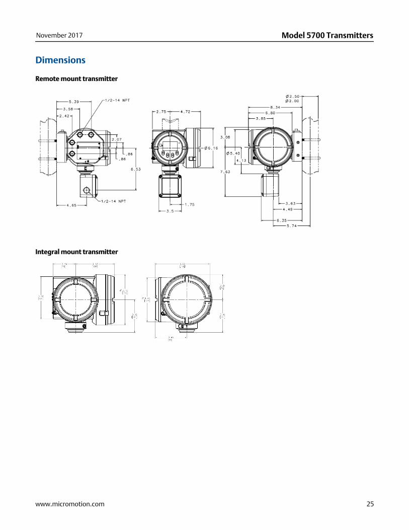
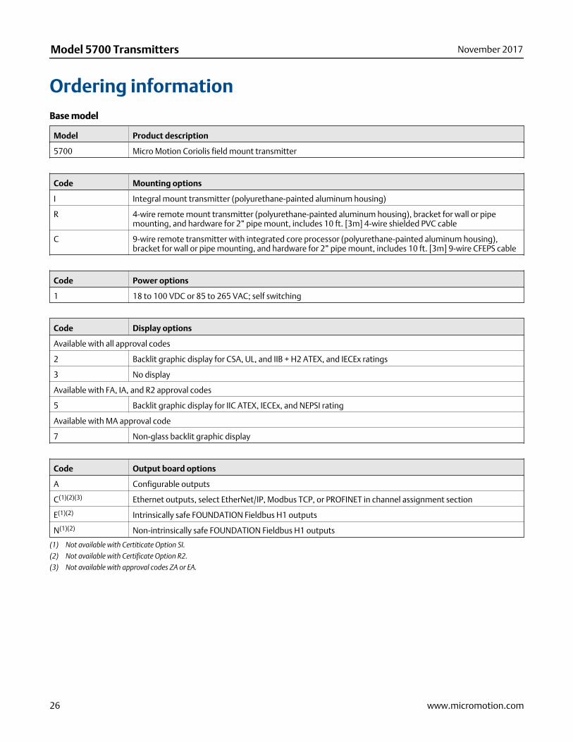
Dimensions
Remote mount transmitter
Integral mount transmitter
November 2017 Model 5700 Transmitters
www.micromotion.com 25
Ordering informationBase model
Model Product description
5700 Micro Motion Coriolis field mount transmitter
Code Mounting options
I Integral mount transmitter (polyurethane-painted aluminum housing)
R 4-wire remote mount transmitter (polyurethane-painted aluminum housing), bracket for wall or pipemounting, and hardware for 2” pipe mount, includes 10 ft. [3m] 4-wire shielded PVC cable
C 9-wire remote transmitter with integrated core processor (polyurethane-painted aluminum housing),bracket for wall or pipe mounting, and hardware for 2” pipe mount, includes 10 ft. [3m] 9-wire CFEPS cable
Code Power options
1 18 to 100 VDC or 85 to 265 VAC; self switching
Code Display options
Available with all approval codes
2 Backlit graphic display for CSA, UL, and IIB + H2 ATEX, and IECEx ratings
3 No display
Available with FA, IA, and R2 approval codes
5 Backlit graphic display for IIC ATEX, IECEx, and NEPSI rating
Available with MA approval code
7 Non-glass backlit graphic display
Code Output board options
A Configurable outputs
C(1)(2)(3) Ethernet outputs, select EtherNet/IP, Modbus TCP, or PROFINET in channel assignment section
E(1)(2) Intrinsically safe FOUNDATION Fieldbus H1 outputs
N(1)(2) Non-intrinsically safe FOUNDATION Fieldbus H1 outputs
(1) Not available with Certiticate Option SI.
(2) Not available with Certificate Option R2.
(3) Not available with approval codes ZA or EA.
Model 5700 Transmitters November 2017
26 www.micromotion.com
Code Conduit connection options
B 1/2-inch NPT – no gland
C(1) 1/2-inch NPT with brass/nickel cable gland
D(1) 1/2-inch NPT with stainless steel cable gland
E M20 - no gland
F(1) M20 with brass/nickel cable gland
G(1) M20 with stainless steel cable gland
(1) Not approved in Class 1 Division 1 installations.
Code Approval options
MA Micro Motion Standard (no approval)
AA CSA (US and Canada): Class I, Division 1, Groups C and D
ZA ATEX: II 2G, Ex db e, Zone 1 and II 2D Ex tb, Zone 21
FA ATEX: II 2G, Ex d, Zone 1 and II 2D Ex tb, Zone 21
IA IECEx: EPL Gb, Ex d, Zone 1 and EPL Db Ex tb, Zone 21
EA IECEx: EPL Gb, Ex db e, Zone 1 and EPL Db Ex tb, Zone 21
2A CSA (US and Canada): Class I, Division 2, Groups A, B, C, D; sensor connections will be intrinsically safe with-out additional barrier
VA(1) ATEX: II 3G, Ex nA nC, Zone 2 and II 3D Ex tc Zone 22
3A(1) IECEx: EPL Gc, Ex nA nC, Zone 2 and EPL Dc, Ex tc, Zone 22
R2 EAC: Ex d, Zone 1
(1) Sensor connections will be Intrinsically Safe without additional barrier.
Code Transmitter option 1
Z Standard product
Code Transmitter option 2
Z Standard product
Code Factory options
Z Standard product
X ETO product
Channel Code Output channel assignment
A Available with output board code A
Z Channel Off
A Channel On; mA Output with HART
Available with output hardware board code C
C EtherNet/IP output 1
D Modbus TCP output 1
H PROFINET output 1
November 2017 Model 5700 Transmitters
www.micromotion.com 27

Channel Code Output channel assignment
Available with output hardware board code E, N
F FOUNDATION Fieldbus output
B Available with output hardware board code A
Z Channel Off
A Channel On; Configurable to mA Output, Frequen-cy Output, and Discrete Output
Available with output hardware board code C (selection must match Channel A)
C EtherNet/IP output 2
D Modbus TCP output 2
H PROFINET output 2
Available with output hardware board code E, N
E Channel On; mA output
C Available with output hardware board code A
Z Channel Off
A Channel On; Configurable to mA output, frequen-cy output, discrete output, and discrete input
Available with output hardware board code C
C Configurable to mA output, frequency output, dis-crete output, and discrete input
Available with output hardware board code E, N
E Channel On; Configurable to frequency output,and discrete output
D Available with output hardware board code A
Z Channel Off
A Channel On; Configurable to mA input, frequencyinput, frequency output, discrete output, and dis-crete input
Available with output hardware board code C
Z Channel Off
Available with output hardware board code E, N
Z Channel Off
E Available with output hardware board code A
Z Channel Off
On; printing support
A On; RS-485 Modbus and RS-485 HART
Available with output hardware board code C
Z Channel Off
Available with output hardware board code E, N
Z Channel Off
Model 5700 Transmitters November 2017
28 www.micromotion.com
Code Additional features (all optional)
Instrument tagging
TG Instrument Tagging -- customer information required (maximum 24 characters)
Meter verification
MV(1) Smart Meter Verification
Weights and measures approval
Requires output board code A (or C for option NT only) and display code 2, 5 or 7 (select only one from this group)
NT Weights and measures custody transfer approval - NTEP
OG Weights and measures custody transfer approval - MID & OIML for Gas
OL Weights and measures custody transfer approval - MID & OIML for Liquid
Enhanced measurement (select only one from this group)
PS(2) API Referral software
CM(2) Concentration Measurement software
Additional software options (select any from this group)
BS(3)(2) Batching Software package
Advanced Phase Measurement (select any from this group)
PG(4) Advanced Phase Measurement Gas with Liquid
PL(4) Advanced Phase Measurement Liquid with Gas
PO(4) Advanced Phase Measurement Net Oil
Additional Certifications, Requires output code A for Channel A and Channel D
SI Safety certification of 4-20 mA outputs per IEC 61508
Smart Wireless 775 THUM requires output code A for Channel A (select only one from this group)
PI(5) Smart Wireless 775 THUM Ready - 775 ordered separately and assembled to 5700
NI Smart Wireless 775 THUM Ready - 775 ordered separately and not assembled to 5700
Ethernet connectors, requires output hardware board code C (select only one from this group)
CA(6) (2) M12 Connectors for Ethernet ports
CB(6) (2) M12 Connectors for Ethernet ports and (1) for Channel C and (1) for Power
(1) Available with all Mounting Options, but Mounting C is limited to 60 ft (20m) of 9-wire cable and only available when purchased with new 9-wiresensor.
(2) Not available with Certificate Option SI.
(3) Not available with either Output Hardware Board E or N.
(4) Not available with Add on options NT or SI.
(5) Smart Wireless ready transmitter add on Option "PI" is only available with Approval Options 2A, VA, and 3A.
(6) Only available with approval codes MA and 2A.
November 2017 Model 5700 Transmitters
www.micromotion.com 29

Model 5700 Transmitters November 2017
30 www.micromotion.com

November 2017 Model 5700 Transmitters
www.micromotion.com 31

Model 5700 TransmittersPS-001885, Rev G
Product Data SheetNovember 2017
Emerson Automation SolutionsWorldwide Headquarters7070 Winchester CircleBoulder, Colorado USA 80301T: +1 800-522-6277T: +1 303-527-5200F: +1 303-530-8459Mexico: 52 55 5809 5300Argentina: 54 11 4837 7000Brazil: 55 15 3413 8147Chile: 56 2 2928 4800
Emerson Automation SolutionsCentral Europe: +41 41 7686 111Eastern Europe: +41 41 7686 111Dubai: +971 4 811 8100Abu Dhabi: +971 2 697 2000France: 0800 917 901Germany: +49 (0) 2173 3348 0Italy: 8008 77334The Netherlands: +31 (0) 70 413 6666Belgium: +32 2 716 77 11Spain: +34 913 586 000U.K.: 0870 240 1978Russian/CIS: +7 495 981 9811
Emerson Automation SolutionsAustralia: (61) 3 9721 0200China: (86) 21 2892 9000India: (91) 22 6662 0566Japan: (81) 3 5769 6803South Korea: (82) 31 8034 0000Singapore: (65) 6 777 8211
©2017 Micro Motion, Inc. All rights reserved.
The Emerson logo is a trademark and service mark of Emerson Electric Co. Micro Motion, ELITE,ProLink, MVD and MVD Direct Connect marks are marks of one of the Emerson AutomationSolutions family of companies. All other marks are property of their respective owners.