Embed Size (px)
Citation preview
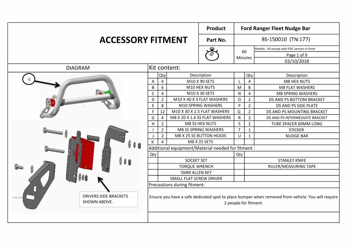
Models : All except with PDC sensors in front
Qty Qty Description
A 4 L 4 M8 HEX NUTS
B 6 M 8 M8 FLAT WASHERS
C 4 N 4 M8 SPRING WASHERS
D 2 O 2 DS AND PS BOTTOM BRACKET
E 8 P 2 DS AND PS SIDE PLATE
F 12 Q 2 DS AND PS MOUNTING BRACKET
G 4 R 2 DS AND PS INTERMEDIATE BRACKET
H 2 S 2 TUBE SPACER 60MM LONG
I 2 T 1 STICKER
J 2 U 1 NUDGE BAR
K 4
Qty Qty
M8 X 25 SETS
SOCKET SET
TORQUE WRENCH
5MM ALLEN KEY
Additional equipment/Material needed for fitment :
STANLEY KNIFE
RULER/MEASURING TAPE
SMALL FLAT SCREW DRIVER
M10 X 90 SETS
Kit content:
60
Minutes
DIAGRAM
M10 X 30 X 2.5 FLAT WASHERS
M8 X 20 X 1.6 SS FLAT WASHERS
Description
Precautions during fitment:
Ensure you have a safe dedicated spot to place bumper when removed from vehicle. You will require
2 people for fitment.
M10 HEX NUTS
M10 X 30 SETS
M10 X 40 X 3 FLAT WASHERS
M10 SPRING WASHERS
M8 X 25 SS BUTTON HEADS
M8 SS HEX NUTS
M8 SS SPRING WASHERS
ACCESSORY FITMENT
U
DRIVERS SIDE BRACKETS SHOWN ABOVE.
Page 1 of 9
03/10/2018
Product Ford Ranger Fleet Nudge Bar
Part No.
Page 2 of 9
Step # Description/MethodVisual / Graphic Illustration
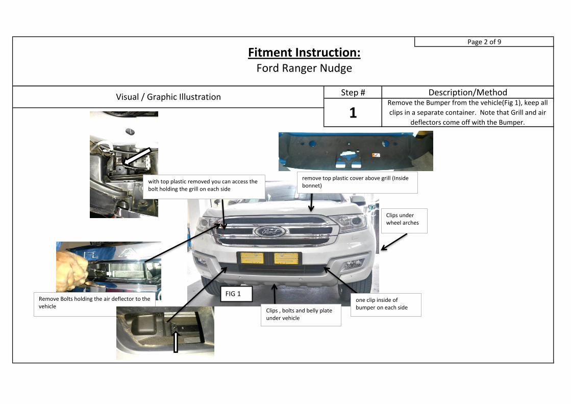
1Remove the Bumper from the vehicle(Fig 1), keep all
clips in a separate container. Note that Grill and air
deflectors come off with the Bumper.
Fitment Instruction: Ford Ranger Nudge
Clips under wheel arches
Clips , bolts and belly plate under vehicle
one clip inside of bumper on each side
with top plastic removed you can access the bolt holding the grill on each side
remove top plastic cover above grill (Inside bonnet)
FIG 1 Remove Bolts holding the air deflector to the vehicle
Page 3 of 9
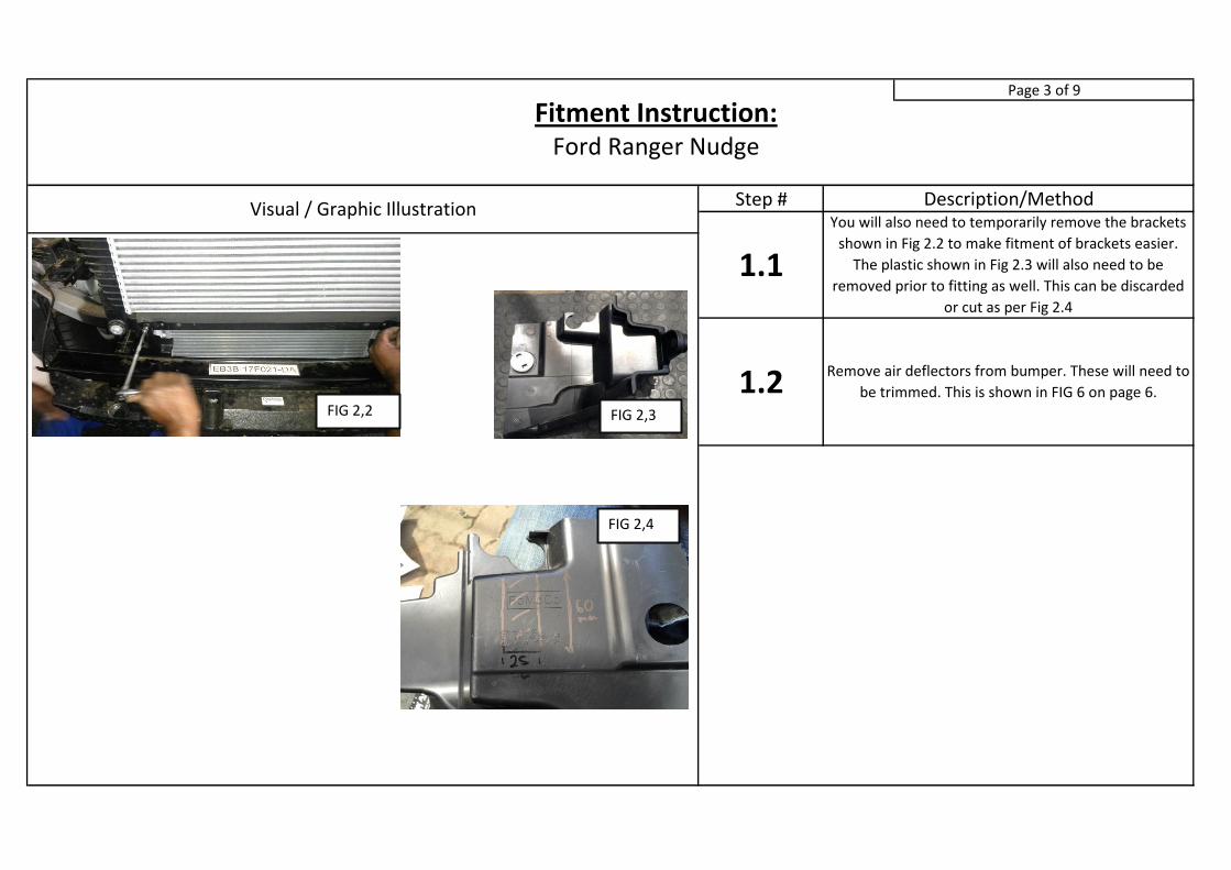
Step #Visual / Graphic Illustration Description/MethodYou will also need to temporarily remove the brackets
shown in Fig 2.2 to make fitment of brackets easier.
The plastic shown in Fig 2.3 will also need to be
removed prior to fitting as well. This can be discarded
or cut as per Fig 2.4
1.1
1.2 Remove air deflectors from bumper. These will need to
be trimmed. This is shown in FIG 6 on page 6.
Fitment Instruction: Ford Ranger Nudge
FIG 2,2 FIG 2,3
FIG 2,4
Page 4 of 9
Step #Visual / Graphic Illustration Description/Method
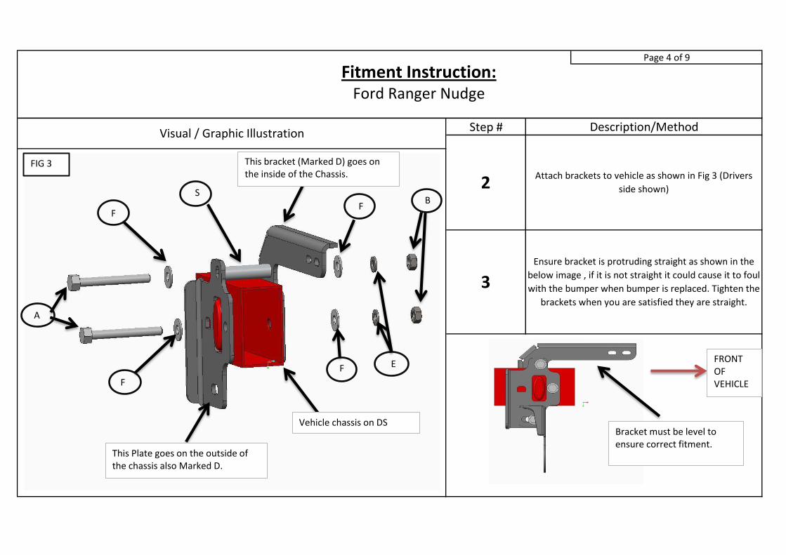
2Attach brackets to vehicle as shown in Fig 3 (Drivers
side shown)
3Ensure bracket is protruding straight as shown in the
below image , if it is not straight it could cause it to foul
with the bumper when bumper is replaced. Tighten the
brackets when you are satisfied they are straight.
Fitment Instruction: Ford Ranger Nudge
Vehicle chassis on DS
This bracket (Marked D) goes on the inside of the Chassis.
S
This Plate goes on the outside of the chassis also Marked D.
A
B
F
F
F
F E
FIG 3
Bracket must be level to ensure correct fitment.
FRONT OF VEHICLE
Page 5 of 9
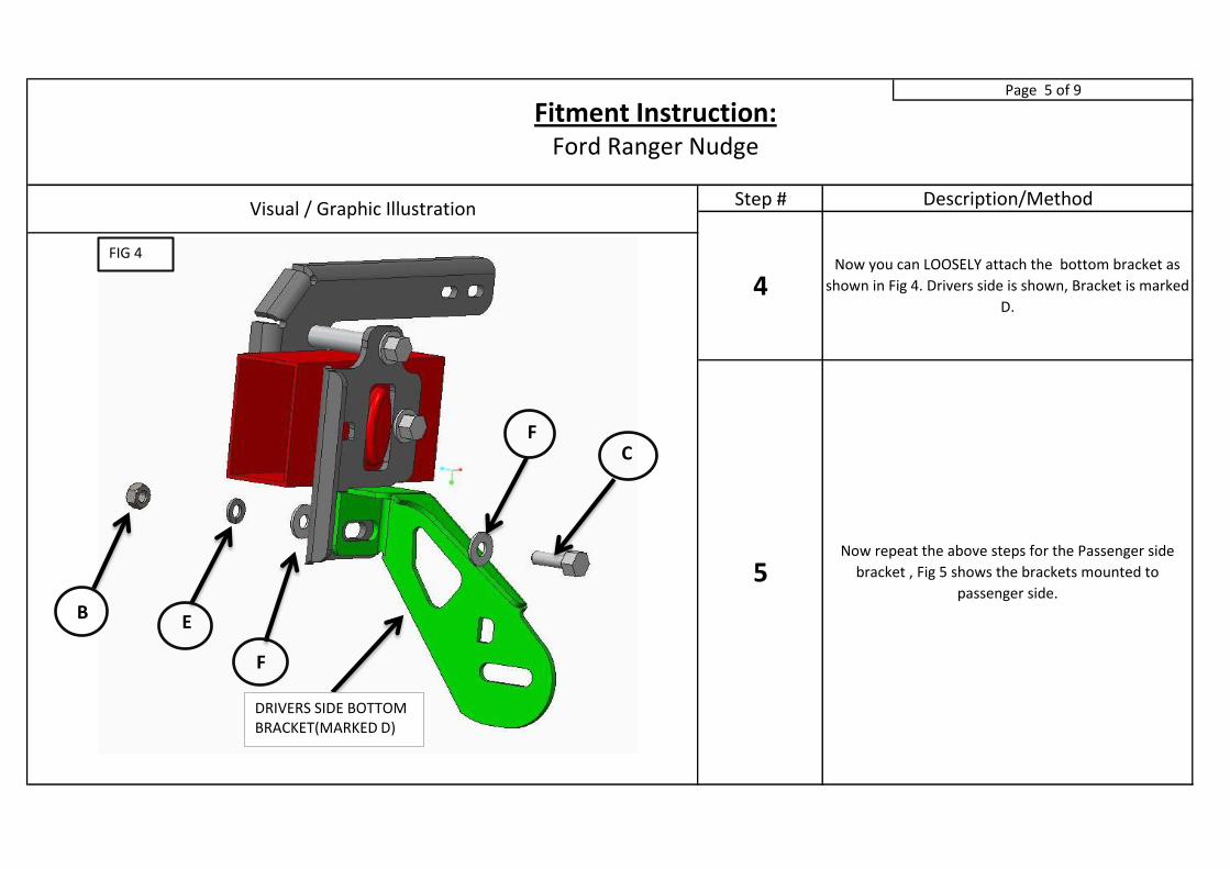
Step #Visual / Graphic Illustration Description/Method
4Now you can LOOSELY attach the bottom bracket as
shown in Fig 4. Drivers side is shown, Bracket is marked
D.
5Now repeat the above steps for the Passenger side
bracket , Fig 5 shows the brackets mounted to
passenger side.
Fitment Instruction: Ford Ranger Nudge
FIG 4
C F
F
E B
DRIVERS SIDE BOTTOM BRACKET(MARKED D)
Page 6 of 9
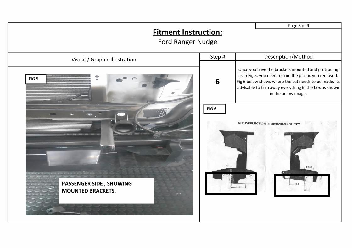
Step #Visual / Graphic Illustration Description/Method
6
Once you have the brackets mounted and protruding
as in Fig 5, you need to trim the plastic you removed.
Fig 6 below shows where the cut needs to be made. Its
advisable to trim away everything in the box as shown
in the below image.
Fitment Instruction: Ford Ranger Nudge
FIG 5
PASSENGER SIDE , SHOWING MOUNTED BRACKETS.
FIG 6
Page 7 of 9
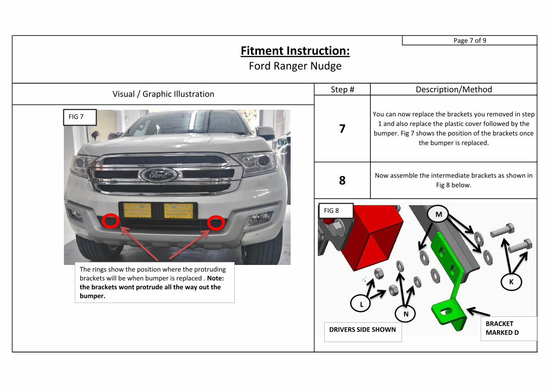
Step #Visual / Graphic Illustration Description/Method
7You can now replace the brackets you removed in step
1 and also replace the plastic cover followed by the
bumper. Fig 7 shows the position of the brackets once
the bumper is replaced.
8Now assemble the intermediate brackets as shown in
Fig 8 below.
Fitment Instruction: Ford Ranger Nudge
The rings show the position where the protruding brackets will be when bumper is replaced . Note: the brackets wont protrude all the way out the bumper.
FIG 7
DRIVERS SIDE SHOWN
L
M
K
N BRACKET MARKED D
FIG 8
Page 8 of 9
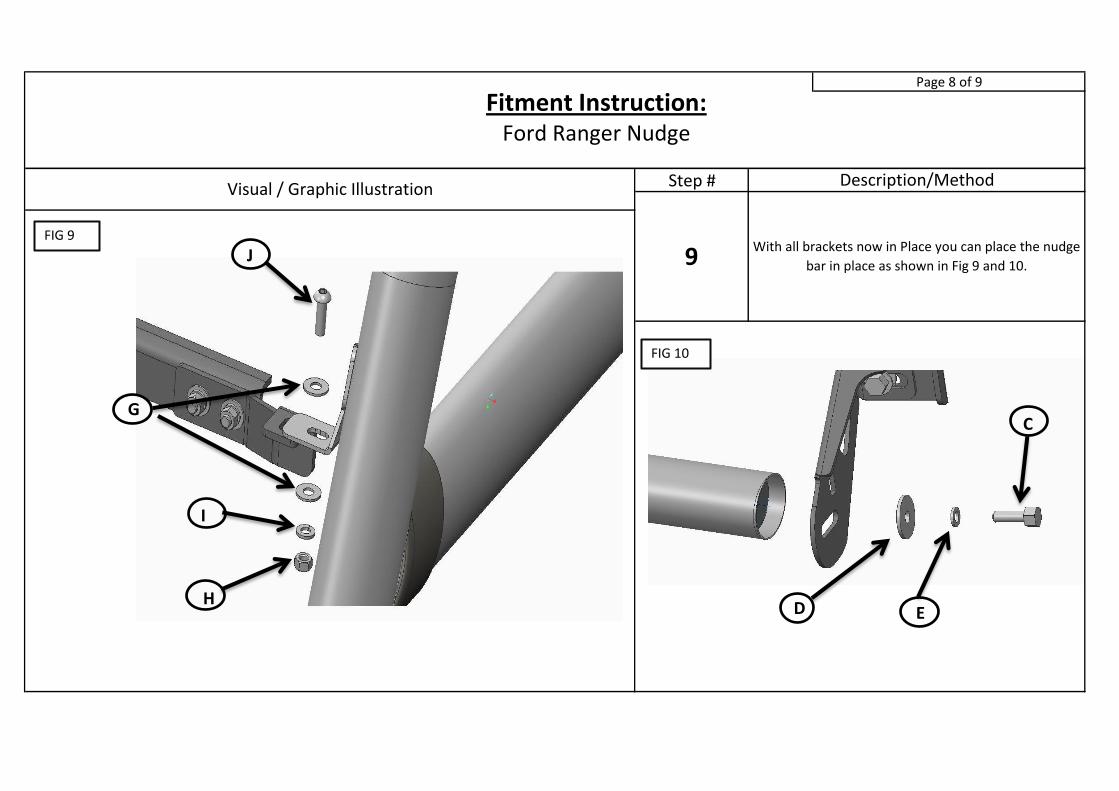
Step #Visual / Graphic Illustration Description/Method
9With all brackets now in Place you can place the nudge
bar in place as shown in Fig 9 and 10.
Fitment Instruction: Ford Ranger Nudge
FIG 9
FIG 10
J
I
H
G
E D
C

Final stepPage 9 of 9
Make sure bar is centralised and tighten all fasteners to specified torque. M8=
22Nm , M10= 42Nm , M6= 9Nm.