Embed Size (px)
Citation preview

GHM Messtechnik GmbHHans-Sachs-Str. 26 93128 Regenstauf Germany Fon +49 (0) 9402 - 9383 - 0 Fax - 33www.ghm-messtechnik.de [email protected]
Product Information Sensors and Instrumentation
Flow - turbine
CharacteristicsSystem Turbine RT
Evaluation Display, switching,measurement
Nominal widths DN 15..50
Range 1.8..1133 l/min
Media WaterAqueous emulsionsAggressive media(Oils)
Pressureresistance
Max. 250 bar
Mediumtemperature
-20..+100 °C
Applications Industrial metering and monitoring
technology
Test equipment
Oil circulation control
pi-ho-sm-flow-turbine_e V1.00-00
1
GHM Messtechnik GmbHHans-Sachs-Str. 26 93128 Regenstauf Germany Fon +49 (0) 9402 - 9383 - 0 Fax - 33www.ghm-messtechnik.de [email protected]
Product Information Sensors and Instrumentation
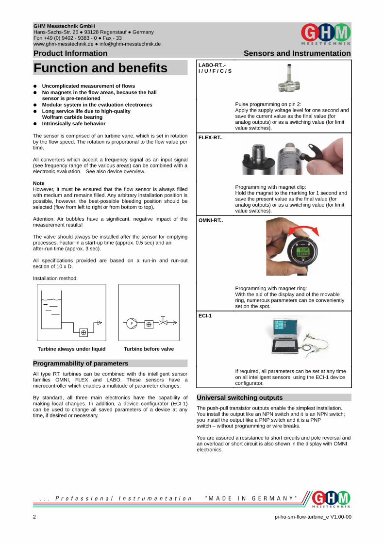
Function and benefits Uncomplicated measurement of flows No magnets in the flow areas, because the hall
sensor is pre-tensioned Modular system in the evaluation electronics Long service life due to high-quality
Wolfram carbide bearing Intrinsically safe behaviorThe sensor is comprised of an turbine vane, which is set in rotation by the flow speed. The rotation is proportional to the flow value per time.
All converters which accept a frequency signal as an input signal (see frequency range of the various areas) can be combined with a electronic evaluation. See also device overview.
NoteHowever, it must be ensured that the flow sensor is always filled with medium and remains filled. Any arbitrary installation position is possible, however, the best-possible bleeding position should be selected (flow from left to right or from bottom to top).
Attention: Air bubbles have a significant, negative impact of the measurement results!
The valve should always be installed after the sensor for emptying processes. Factor in a start-up time (approx. 0.5 sec) and an after-run time (approx. 3 sec).
All specifications provided are based on a run-in and run-out section of 10 x D. Installation method:
Turbine always under liquid Turbine before valve
Programmability of parameters
All type RT. turbines can be combined with the intelligent sensor families OMNI, FLEX and LABO. These sensors have a microcontroller which enables a multitude of parameter changes.
By standard, all three main electronics have the capability of making local changes. In addition, a device configurator (ECI-1) can be used to change all saved parameters of a device at any time, if desired or necessary.
LABO-RT..- I / U / F / C / S
Pulse programming on pin 2:Apply the supply voltage level for one second and save the current value as the final value (for analog outputs) or as a switching value (for limit value switches).
FLEX-RT..
Programming with magnet clip:Hold the magnet to the marking for 1 second and save the present value as the final value (for analog outputs) or as a switching value (for limit value switches).
OMNI-RT..
Programming with magnet ring:With the aid of the display and of the movable ring, numerous parameters can be conveniently set on the spot.
ECI-1
If required, all parameters can be set at any time on all intelligent sensors, using the ECI-1 device configurator.
Universal switching outputs
The push-pull transistor outputs enable the simplest installation. You install the output like an NPN switch and it is an NPN switch; you install the output like a PNP switch and it is a PNP switch – without programming or wire breaks.
You are assured a resistance to short circuits and pole reversal and an overload or short circuit is also shown in the display with OMNI electronics.
2 pi-ho-sm-flow-turbine_e V1.00-00
GHM Messtechnik GmbHHans-Sachs-Str. 26 93128 Regenstauf Germany Fon +49 (0) 9402 - 9383 - 0 Fax - 33www.ghm-messtechnik.de [email protected]
Product Information Sensors and Instrumentation
Device overview
De
vic
e
R
an
ge
l/min
Pre
ssu
re r
esi
sta
nce
Med
ium
te
mp
erat
ure
Su
pp
ly v
olt
ag
e
Dis
pla
y
Output signal Pag
e
Sw
itch
ing
Mea
suri
ng
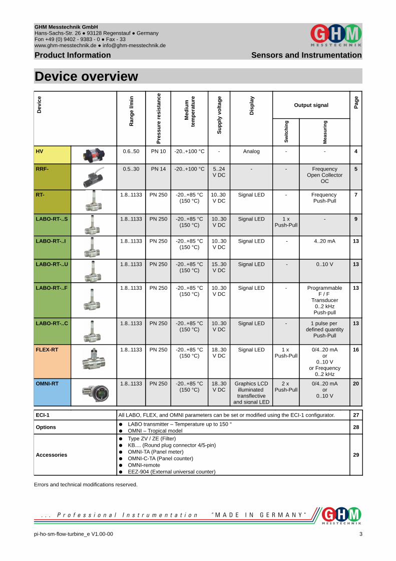
HV 0.6..50 PN 10 -20..+100 °C - Analog - - 4
RRF- 0.5..30 PN 14 -20..+100 °C 5..24V DC
- - FrequencyOpen Collector
OC
5
RT- 1.8..1133 PN 250 -20..+85 °C(150 °C)
10..30 V DC
Signal LED - Frequency Push-Pull
7
LABO-RT-..S 1.8..1133 PN 250 -20..+85 °C(150 °C)
10..30V DC
Signal LED 1 xPush-Pull
- 9
LABO-RT-..I 1.8..1133 PN 250 -20..+85 °C(150 °C)
10..30V DC
Signal LED - 4..20 mA 13
LABO-RT-..U 1.8..1133 PN 250 -20..+85 °C(150 °C)
15..30V DC
Signal LED - 0..10 V 13
LABO-RT-..F 1.8..1133 PN 250 -20..+85 °C(150 °C)
10..30V DC
Signal LED - Programmable F / F
Transducer 0..2 kHzPush-pull
13
LABO-RT-..C 1.8..1133 PN 250 -20..+85 °C(150 °C)
10..30V DC
Signal LED - 1 pulse per defined quantity
Push-Pull
13
FLEX-RT 1.8..1133 PN 250 -20..+85 °C(150 °C)
18..30V DC
Signal LED 1 x Push-Pull
0/4..20 mAor
0..10 Vor Frequency
0..2 kHz
16
OMNI-RT 1.8..1133 PN 250 -20..+85 °C(150 °C)
18..30V DC
Graphics LCDilluminated transflective
and signal LED
2 x Push-Pull
0/4..20 mAor
0..10 V
20
ECI-1 All LABO, FLEX, and OMNI parameters can be set or modified using the ECI-1 configurator. 27
Options LABO transmitter – Temperature up to 150 ° OMNI – Tropical model
28
Accessories
Type ZV / ZE (Filter) KB.... (Round plug connector 4/5-pin) OMNI-TA (Panel meter) OMNI-C-TA (Panel counter) OMNI-remote EEZ-904 (External universal counter)
29
Errors and technical modifications reserved.
pi-ho-sm-flow-turbine_e V1.00-00
3
Honsberg Instruments GmbH Tenter Weg 2-8 42897 Remscheid Germany Fon +49 (0) 2191 - 9672 - 0 Fax - 40www.honsberg.com [email protected]
Product Information Sensors and Instrumentation
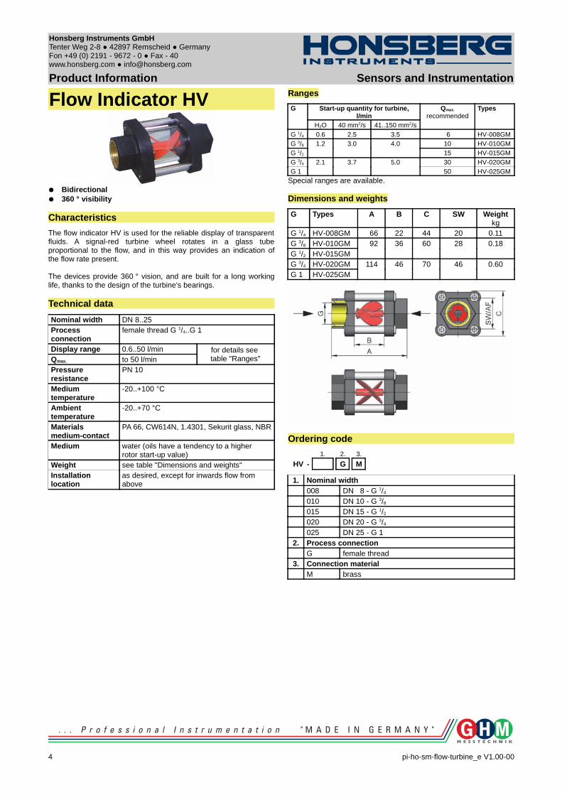
Flow Indicator HV
Bidirectional 360 ° visibility
Characteristics
The flow indicator HV is used for the reliable display of transparent fluids. A signal-red turbine wheel rotates in a glass tube proportional to the flow, and in this way provides an indication of the flow rate present.
The devices provide 360 ° vision, and are built for a long working life, thanks to the design of the turbine's bearings.
Technical data
Nominal width DN 8..25Process connection
female thread G 1/4..G 1
Display range 0.6..50 l/min for details see table "Ranges"Qmax. to 50 l/min
Pressure resistance
PN 10
Medium temperature
-20..+100 °C
Ambient temperature
-20..+70 °C
Materialsmedium-contact
PA 66, CW614N, 1.4301, Sekurit glass, NBR
Medium water (oils have a tendency to a higher rotor start-up value)
Weight see table "Dimensions and weights"Installation location
as desired, except for inwards flow from above
Ranges
G Start-up quantity for turbine, l/min
Qmax.
recommendedTypes
H2O 40 mm2/s 41..150 mm2/s
G 1/4 0.6 2.5 3.5 6 HV-008GMG 3/8 1.2 3.0 4.0 10 HV-010GMG 1/2 15 HV-015GM
G 3/4 2.1 3.7 5.0 30 HV-020GMG 1 50 HV-025GM
Special ranges are available.
Dimensions and weights
G Types A B C SW Weightkg
G 1/4 HV-008GM 66 22 44 20 0.11G 3/8 HV-010GM 92 36 60 28 0.18G 1/2 HV-015GMG 3/4 HV-020GM 114 46 70 46 0.60G 1 HV-025GM
Ordering code
1. 2. 3.
HV - G M
1. Nominal width008 DN 8 - G 1/4
010 DN 10 - G 3/8
015 DN 15 - G 1/2
020 DN 20 - G 3/4
025 DN 25 - G 12. Process connection
G female thread3. Connection material
M brass
4 pi-ho-sm-flow-turbine_e V1.00-00
Honsberg Instruments GmbH Tenter Weg 2-8 42897 Remscheid Germany Fon +49 (0) 2191 - 9672 - 0 Fax - 40www.honsberg.com [email protected]
Product Information Sensors and Instrumentation
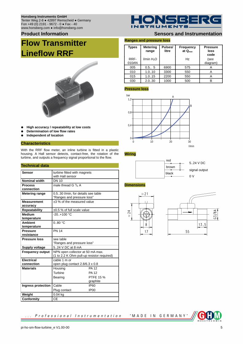
Flow TransmitterLineflow RRF
High accuracy / repeatability at low costs Determination of low flow rates Independent of location
Characteristics
With the RRF flow meter, an inline turbine is fitted in a plastic housing. A Hall sensor detects, contact-free, the rotation of the turbine, and outputs a frequency signal proportional to the flow.
Technical data
Sensor turbine fitted with magnets with Hall sensor
Nominal width DN 10 Process connection
male thread G 3/8 A
Metering range 0.5..30 l/min, for details see table "Ranges and pressure loss"
Measurement accuracy
±3 % of the measured value
Repeatability ±0.5 % of full scale valueMedium temperature
-20..+100 °C
Ambient temperature
0..80 °C
Pressure resistance
PN 14
Pressure loss see table "Ranges and pressure loss"
Supply voltage 5..24 V DC at 8 mAFrequency output NPN open collector at 50 mA max.
(1 to 2.2 K Ohm pull-up resistor required)Electrical connection
cable 1 m or open plug contact 2.8/6.3 x 0.8
Materials Housing PA 12Turbine PA 12Bearing PTFE 15 %
graphiteIngress protection Cable IP60
Plug contact IP00Weight 0.04 kgConformity CE
Ranges and pressure loss
Types Metering range
Pulses/litre
Frequencyat Qmax
Pressure losscode
RRF-010AN
l/min H2O Hz (see diagram)
005 0.5.. 5 6900 575 A010 1.0..10 3300 550 A015 1.0..15 2200 550 A030 2.0..30 1000 500 B
Pressure loss
Wiring
Dimensions
pi-ho-sm-flow-turbine_e V1.00-00
5
1,2bar
l/min
3020100
0,8
0,4
0
A
B
red
brown
black
5..24 V DC
signal output
0 V
Honsberg Instruments GmbH Tenter Weg 2-8 42897 Remscheid Germany Fon +49 (0) 2191 - 9672 - 0 Fax - 40www.honsberg.com [email protected]
Product Information Sensors and InstrumentationHandling and Operation
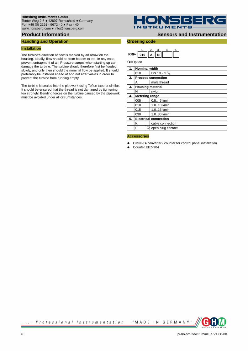
Installation
The turbine's direction of flow is marked by an arrow on the housing. Ideally, flow should be from bottom to top. In any case, prevent entrapment of air. Pressure surges when starting up can damage the turbine. The turbine should therefore first be flooded slowly, and only then should the nominal flow be applied. It should preferably be installed ahead of and not after valves in order to prevent the turbine from running empty.
The turbine is sealed into the pipework using Teflon tape or similar. It should be ensured that the thread is not damaged by tightening too strongly. Bending forces on the turbine caused by the pipework must be avoided under all circumstances.
Ordering code
1. 2. 3. 4. 5.
RRF- 010 A N
=Option
1. Nominal width010 DN 10 - G 3/8
2. Process connectionA male thread
3. Housing materialN nylon
4. Metering range005 0.5.. 5 l/min010 1.0..10 l/min015 1.0..15 l/min030 1.0..30 l/min
5. Electrical connectionK cable connectionF open plug contact
Accessories
OMNI-TA converter / counter for control panel installation Counter EEZ-904
6 pi-ho-sm-flow-turbine_e V1.00-00

Honsberg Instruments GmbH Tenter Weg 2-8 42897 Remscheid Germany Fon +49 (0) 2191 - 9672 - 0 Fax - 40www.honsberg.com [email protected]
Product Information Sensors and Instrumentation
Flow TransmitterRT-...AK
High precision No magnetic components in the flow space High pressure resistance
Characteristics
A turbine acts as the primary sensor; its rotational speed is proportional to the flow rate. The rotational speed is detected by means of a biased Hall sensors, i.e. there are no magnets in the flow space.
Technical data
Sensor biased Hall sensorNominal width DN 15..50Process connection
male thread G 1/2 A...G 2 A
Metering ranges 1.8..1133 l/min for details, see table "Ranges"
Measurement accuracy
±1 % of full scale valuein the specified metering range, including linearity and repeatability
Medium temperature
-20..+85 °Coptionally -20..+150 °C (for 8 bar min.)
Ambient temperature
-20..+70 °C
Storage temperature
-20..+80 °C
Materials medium-contact
Housing stainless steel 315Turbine stainless steel 430Bearing tungsten carbide
Material electronics housing
CW614N nickelled
Max. particle size
0.5 mm
Pressure loss 0.3 bar at Qmax.
Pressure resistance
PN 250
Supply voltage 10..30 V DCSignal output transistor output "push-pull"
(resistant to short circuits and polarity reversal)Iout = 100 mA max.
Current consumption
20 mA without load
Max. load current 100 mA
Electrical connection
for round plug connector M12x1, 4-pole
Ingress protection IP 67Weight see table "Dimensions"Conformity CE
Ranges
Types Metering range (1..5 mm²/s)
Pulses /litre
l/min m³/h ±10 %RT-015AK001. 1.8.. 18 0.11.. 1.1 2900RT-020AK002. 3.7.. 37 0.22.. 2.2 1700RT-020AK004. 6.7.. 67 0.40.. 4.0 1100RT-020AK008. 13.3.. 133 0.80.. 8.0 400RT-025AK016. 26.7.. 267 1.60.. 16.0 190RT-040AK034. 56.7.. 567 3.40.. 34.0 60RT-050AK068. 113.3..1133 6.80.. 68.0 24
Wiring
Push-pull output, can be connected to PNP or NPN inputs.
pi-ho-sm-flow-turbine_e V1.00-00
7
Z Z
1
2
3
4
brown
white
blue
black
10..30 V DC
n.c.
0 V
frequency output
PNP NPNConnection example:
1
43
2
Z=Load
Honsberg Instruments GmbH Tenter Weg 2-8 42897 Remscheid Germany Fon +49 (0) 2191 - 9672 - 0 Fax - 40www.honsberg.com [email protected]
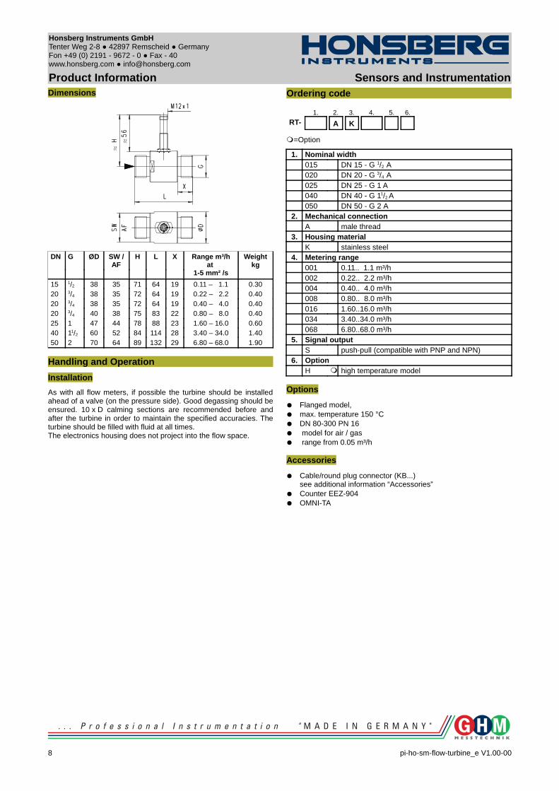
Product Information Sensors and InstrumentationDimensions
DN G ØD SW / AF
H L X Range m³/hat
1-5 mm² /s
Weightkg
15 1/2 38 35 71 64 19 0.11 – 1.1 0.3020 3/4 38 35 72 64 19 0.22 – 2.2 0.4020 3/4 38 35 72 64 19 0.40 – 4.0 0.4020 3/4 40 38 75 83 22 0.80 – 8.0 0.4025 1 47 44 78 88 23 1.60 – 16.0 0.6040 11/2 60 52 84 114 28 3.40 – 34.0 1.4050 2 70 64 89 132 29 6.80 – 68.0 1.90
Handling and Operation
Installation
As with all flow meters, if possible the turbine should be installed ahead of a valve (on the pressure side). Good degassing should be ensured. 10 x D calming sections are recommended before and after the turbine in order to maintain the specified accuracies. The turbine should be filled with fluid at all times. The electronics housing does not project into the flow space.
Ordering code
1. 2. 3. 4. 5. 6.
RT- A K
=Option
1. Nominal width015 DN 15 - G 1/2 A020 DN 20 - G 3/4 A025 DN 25 - G 1 A040 DN 40 - G 11/2 A050 DN 50 - G 2 A
2. Mechanical connectionA male thread
3. Housing materialK stainless steel
4. Metering range001 0.11.. 1.1 m³/h002 0.22.. 2.2 m³/h004 0.40.. 4.0 m³/h008 0.80.. 8.0 m³/h016 1.60..16.0 m³/h034 3.40..34.0 m³/h068 6.80..68.0 m³/h
5. Signal outputS push-pull (compatible with PNP and NPN)
6. OptionH high temperature model
Options
Flanged model, max. temperature 150 °C DN 80-300 PN 16 model for air / gas range from 0.05 m³/h
Accessories
Cable/round plug connector (KB...)see additional information “Accessories”
Counter EEZ-904 OMNI-TA
8 pi-ho-sm-flow-turbine_e V1.00-00
Honsberg Instruments GmbH Tenter Weg 2-8 42897 Remscheid Germany Fon +49 (0) 2191 - 9672 - 0 Fax - 40www.honsberg.com [email protected]
Product Information Sensors and Instrumentation
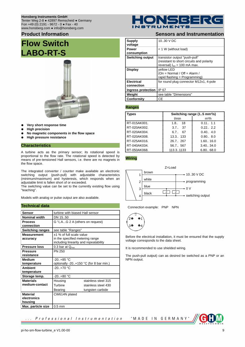
Flow SwitchLABO-RT-S
Very short response time High precision No magnetic components in the flow space High pressure resistance
Characteristics
A turbine acts as the primary sensor; its rotational speed is proportional to the flow rate. The rotational speed is detected by means of pre-tensioned Hall sensors, i.e. there are no magnets in the flow space.
The integrated converter / counter make available an electronic switching output (push-pull) with adjustable characteristics (minimum/maximum) and hysteresis, which responds when an adjustable limit is fallen short of or exceeded.The switching value can be set to the currently existing flow using "teaching".
Models with analog or pulse output are also available.
Technical data
Sensor turbine with biased Hall sensorNominal width DN 15..50Process connection
G 1/2 A...G 2 A (others on request)
Switching ranges see table "Ranges"Measurement accuracy
±1 % of full scale valuein the specified metering rangeincluding linearity and repeatability
Pressure loss 0.3 bar at Qmax.
Pressure resistance
PN 250
Medium temperature
-20..+85 °Coptionally -20..+150 °C (for 8 bar min.)
Ambient temperature
-20..+70 °C
Storage temp. -20..+80 °CMaterials medium-contact
Housing stainless steel 315Turbine stainless steel 430Bearing tungsten carbide
Materialelectronics housing
CW614N plated
Max. particle size 0.5 mm
Supplyvoltage
10..30 V DC
Power consumption
< 1 W (without load)
Switching output transistor output "push-pull"(resistant to short circuits and polarity reversal) lout = 100 mA max.
Display yellow LED (On = Normal / Off = Alarm / rapid flashing = Programming)
Electrical connection
for round plug connector M12x1, 4-pole
Ingress protection IP 67Weight see table "Dimensions"Conformity CE
Ranges
Types Switching range (1..5 mm²/s)l/min m³/h
RT-015AK001. 1.8.. 18 0.11.. 1.1RT-020AK002. 3.7.. 37 0.22.. 2.2RT-020AK004. 6.7.. 67 0.40.. 4.0RT-020AK008. 13.3.. 133 0.80.. 8.0RT-025AK016. 26.7.. 267 1.60.. 16.0RT-040AK034. 56.7.. 567 3.40.. 34.0RT-050AK068. 113.3..1133 6.80.. 68.0
Wiring
Before the electrical installation, it must be ensured that the supply voltage corresponds to the data sheet.
It is recommended to use shielded wiring.
The push-pull output) can as desired be switched as a PNP or an NPN output.
pi-ho-sm-flow-turbine_e V1.00-00
9
Z Z
1
2
3
4
brown
white
blue
black
10..30 V DC
programming
0 V
switching output
PNP NPNConnection example:
1
43
2
Z=Load
Honsberg Instruments GmbH Tenter Weg 2-8 42897 Remscheid Germany Fon +49 (0) 2191 - 9672 - 0 Fax - 40www.honsberg.com [email protected]
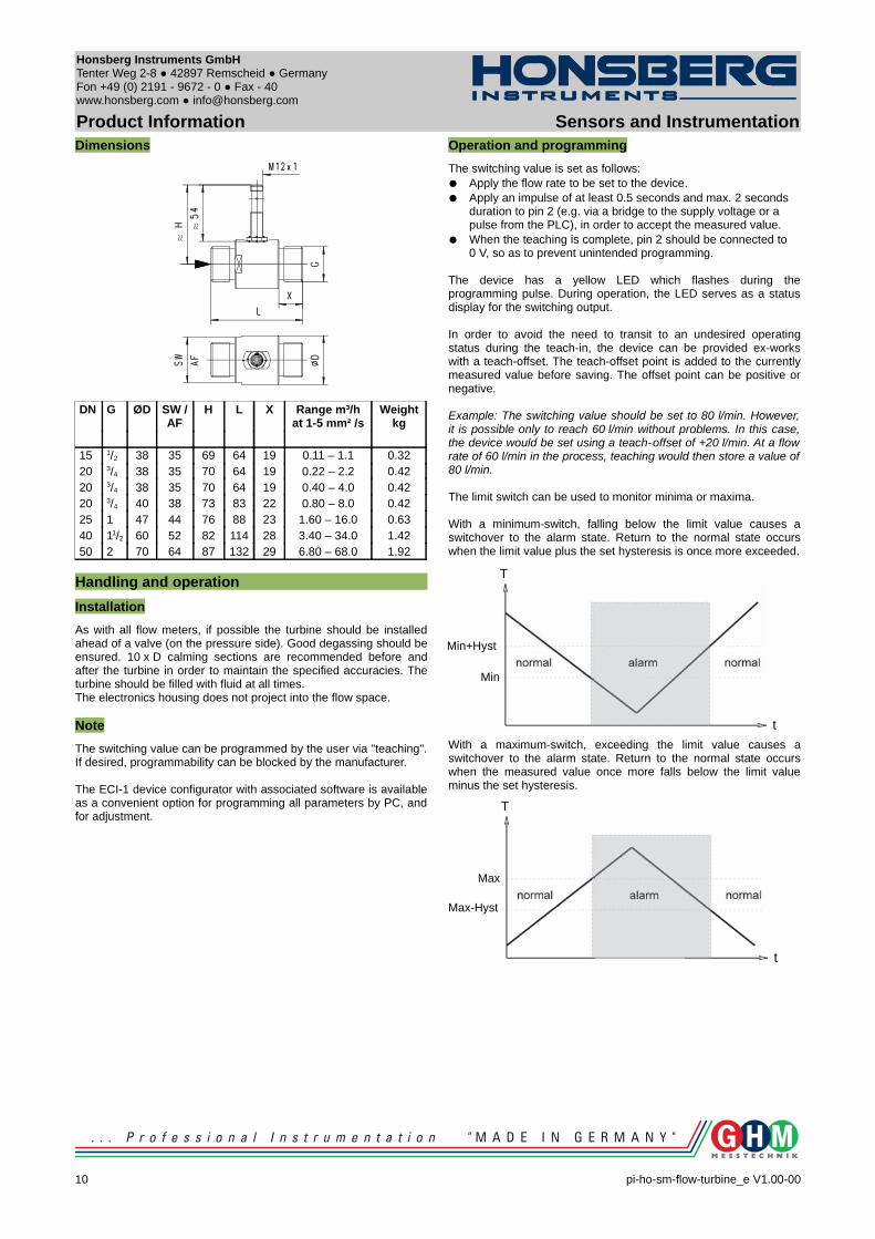
Product Information Sensors and InstrumentationDimensions
DN G ØD SW / AF
H L X Range m³/hat 1-5 mm² /s
Weightkg
15 1/2 38 35 69 64 19 0.11 – 1.1 0.3220 3/4 38 35 70 64 19 0.22 – 2.2 0.4220 3/4 38 35 70 64 19 0.40 – 4.0 0.4220 3/4 40 38 73 83 22 0.80 – 8.0 0.4225 1 47 44 76 88 23 1.60 – 16.0 0.6340 11/2 60 52 82 114 28 3.40 – 34.0 1.4250 2 70 64 87 132 29 6.80 – 68.0 1.92
Handling and operation
Installation
As with all flow meters, if possible the turbine should be installed ahead of a valve (on the pressure side). Good degassing should be ensured. 10 x D calming sections are recommended before and after the turbine in order to maintain the specified accuracies. The turbine should be filled with fluid at all times. The electronics housing does not project into the flow space.
Note
The switching value can be programmed by the user via "teaching". If desired, programmability can be blocked by the manufacturer.
The ECI-1 device configurator with associated software is available as a convenient option for programming all parameters by PC, and for adjustment.
Operation and programming
The switching value is set as follows: Apply the flow rate to be set to the device. Apply an impulse of at least 0.5 seconds and max. 2 seconds
duration to pin 2 (e.g. via a bridge to the supply voltage or a pulse from the PLC), in order to accept the measured value.
When the teaching is complete, pin 2 should be connected to 0 V, so as to prevent unintended programming.
The device has a yellow LED which flashes during the programming pulse. During operation, the LED serves as a status display for the switching output.
In order to avoid the need to transit to an undesired operating status during the teach-in, the device can be provided ex-works with a teach-offset. The teach-offset point is added to the currently measured value before saving. The offset point can be positive or negative.
Example: The switching value should be set to 80 l/min. However, it is possible only to reach 60 l/min without problems. In this case, the device would be set using a teach-offset of +20 l/min. At a flow rate of 60 l/min in the process, teaching would then store a value of 80 l/min.
The limit switch can be used to monitor minima or maxima.
With a minimum-switch, falling below the limit value causes a switchover to the alarm state. Return to the normal state occurs when the limit value plus the set hysteresis is once more exceeded.
With a maximum-switch, exceeding the limit value causes a switchover to the alarm state. Return to the normal state occurs when the measured value once more falls below the limit value minus the set hysteresis.
10 pi-ho-sm-flow-turbine_e V1.00-00
Min
Min+Hyst
t
T
Max-Hyst
t
T
Max
Honsberg Instruments GmbH Tenter Weg 2-8 42897 Remscheid Germany Fon +49 (0) 2191 - 9672 - 0 Fax - 40www.honsberg.com [email protected]
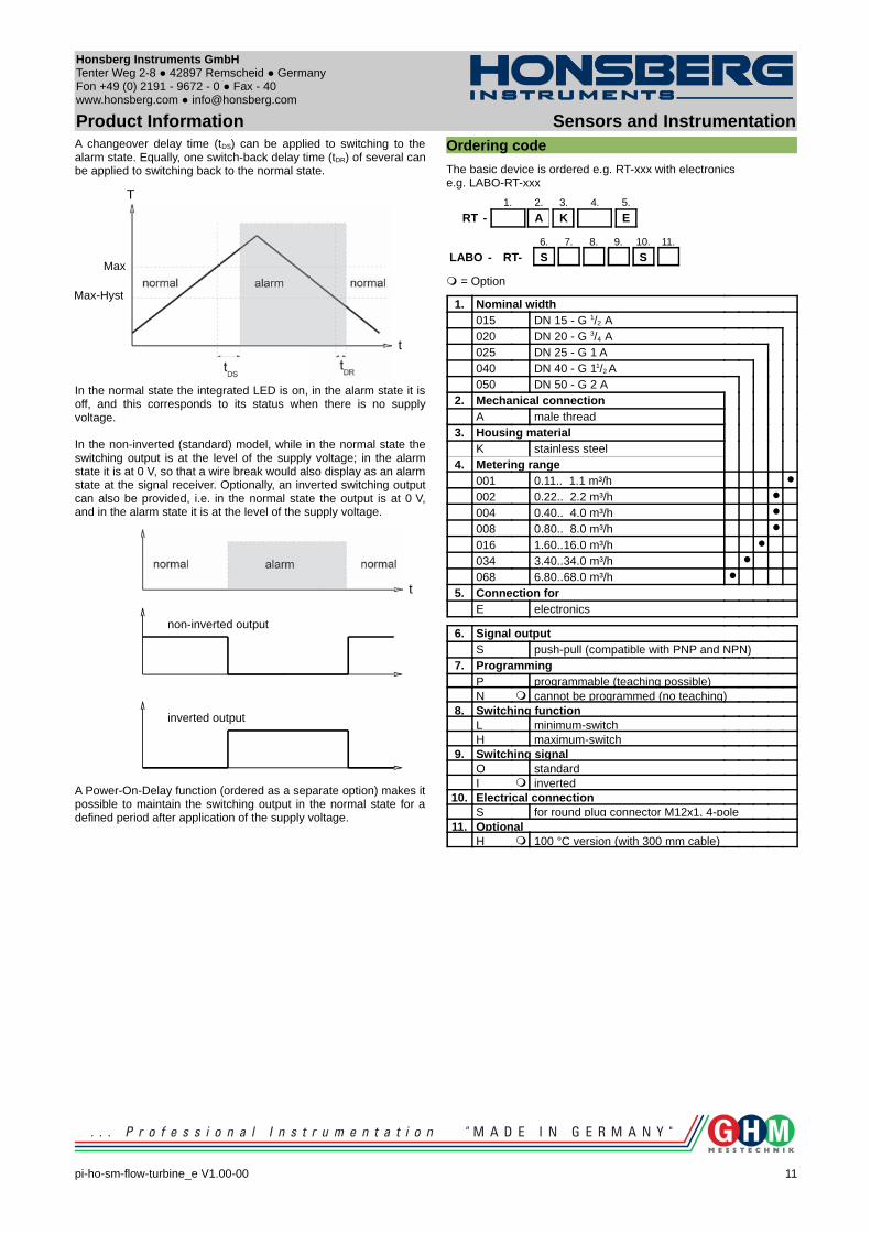
Product Information Sensors and InstrumentationA changeover delay time (tDS) can be applied to switching to the alarm state. Equally, one switch-back delay time (tDR) of several can be applied to switching back to the normal state.
In the normal state the integrated LED is on, in the alarm state it is off, and this corresponds to its status when there is no supply voltage.
In the non-inverted (standard) model, while in the normal state the switching output is at the level of the supply voltage; in the alarm state it is at 0 V, so that a wire break would also display as an alarm state at the signal receiver. Optionally, an inverted switching output can also be provided, i.e. in the normal state the output is at 0 V, and in the alarm state it is at the level of the supply voltage.
A Power-On-Delay function (ordered as a separate option) makes it possible to maintain the switching output in the normal state for a defined period after application of the supply voltage.
Ordering code
The basic device is ordered e.g. RT-xxx with electronics e.g. LABO-RT-xxx
1. 2. 3. 4. 5.
RT - A K E
6. 7. 8. 9. 10. 11.
LABO - RT- S S
= Option
1. Nominal width015 DN 15 - G 1/2 A020 DN 20 - G 3/4 A025 DN 25 - G 1 A040 DN 40 - G 11/2 A050 DN 50 - G 2 A
2. Mechanical connectionA male thread
3. Housing materialK stainless steel
4. Metering range001 0.11.. 1.1 m³/h
002 0.22.. 2.2 m³/h
004 0.40.. 4.0 m³/h
008 0.80.. 8.0 m³/h
016 1.60..16.0 m³/h
034 3.40..34.0 m³/h
068 6.80..68.0 m³/h
5. Connection forE electronics
6. Signal outputS push-pull (compatible with PNP and NPN)
7. ProgrammingP programmable (teaching possible)N cannot be programmed (no teaching)
8. Switching function L minimum-switchH maximum-switch
9. Switching signalO standardI inverted
10. Electrical connectionS for round plug connector M12x1, 4-pole
11. OptionalH 100 °C version (with 300 mm cable)
pi-ho-sm-flow-turbine_e V1.00-00
11
Max-Hyst
t
T
Max
t
non-inverted output
inverted output
Honsberg Instruments GmbH Tenter Weg 2-8 42897 Remscheid Germany Fon +49 (0) 2191 - 9672 - 0 Fax - 40www.honsberg.com [email protected]
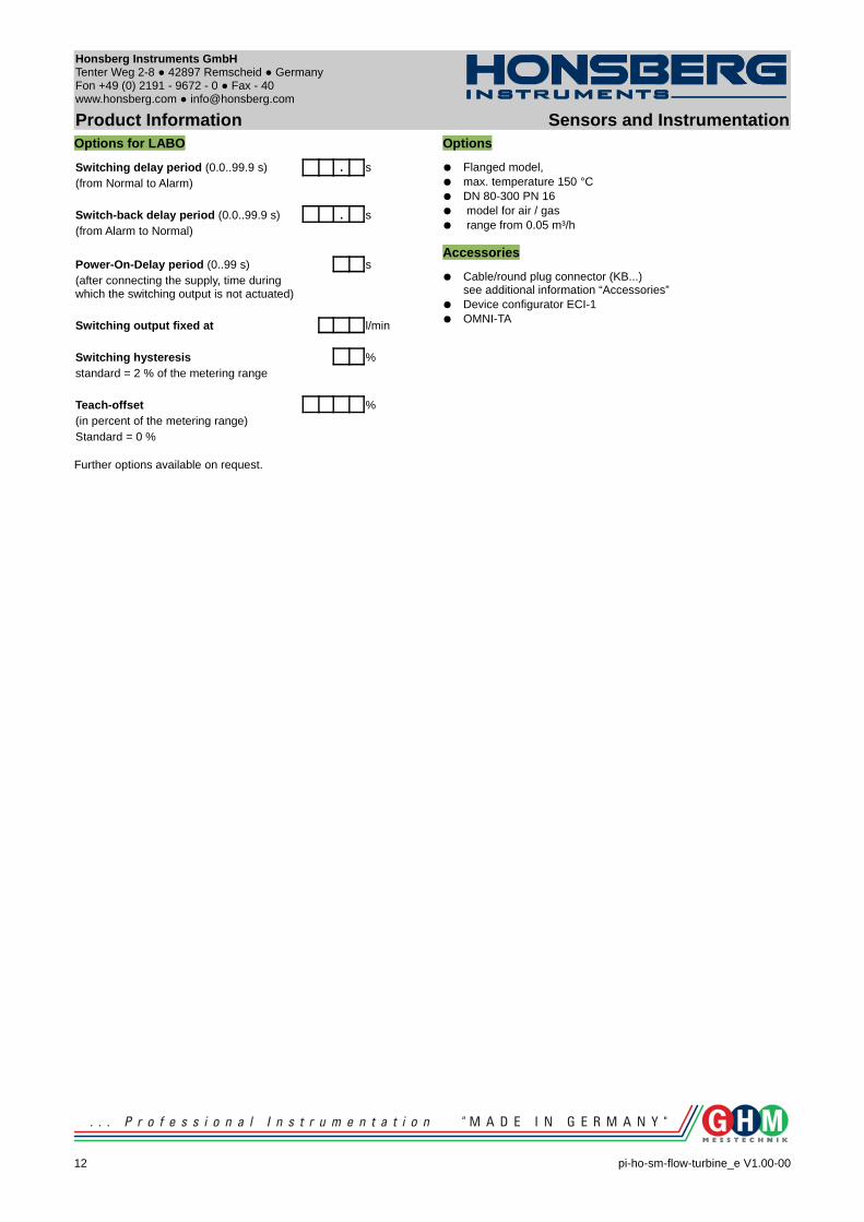
Product Information Sensors and InstrumentationOptions for LABO
Switching delay period (0.0..99.9 s) . s(from Normal to Alarm)
Switch-back delay period (0.0..99.9 s) . s(from Alarm to Normal)
Power-On-Delay period (0..99 s) s(after connecting the supply, time during which the switching output is not actuated)
Switching output fixed at l/min
Switching hysteresis %standard = 2 % of the metering range
Teach-offset %(in percent of the metering range)Standard = 0 %
Further options available on request.
Options
Flanged model, max. temperature 150 °C DN 80-300 PN 16 model for air / gas range from 0.05 m³/h
Accessories
Cable/round plug connector (KB...)see additional information “Accessories”
Device configurator ECI-1 OMNI-TA
12 pi-ho-sm-flow-turbine_e V1.00-00
Honsberg Instruments GmbH Tenter Weg 2-8 42897 Remscheid Germany Fon +49 (0) 2191 - 9672 - 0 Fax - 40www.honsberg.com [email protected]
Product Information Sensors and Instrumentation
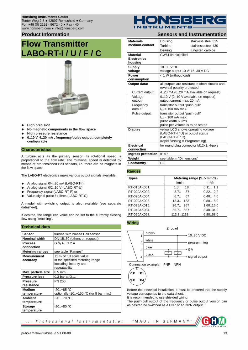
Flow TransmitterLABO-RT-I / U / F / C
High precision No magnetic components in the flow space High pressure resistance 0..10 V, 4..20 mA , frequency/pulse output, completely
configurable
Characteristics
A turbine acts as the primary sensor; its rotational speed is proportional to the flow rate. The rotational speed is detected by means of pre-tensioned Hall sensors, i.e. there are no magnets in the flow space.
The LABO-RT electronics make various output signals available:
Analog signal 0/4..20 mA (LABO-RT-I) Analog signal 0/2..10 V (LABO-RT-U) Frequency signal (LABO-RT-F) or Value signal pulse / x litres (LABO-RT-C)
A model with switching output is also available (see separate datasheet).
If desired, the range end value can be set to the currently existing flow using "teaching".
Technical data
Sensor turbine with biased Hall sensorNominal width DN 15..50 (others on request)Process connection
G 1/2 A...G 2 A
Metering ranges see table "Ranges"Measurement accuracy
±1 % of full scale valuein the specified metering rangeincluding linearity and repeatability
Max. particle size 0.5 mmPressure loss 0.3 bar at Qmax.
Pressure resistance
PN 250
Medium temperature
-20..+85 °Coptionally -20..+150 °C (for 8 bar min.)
Ambient temperature
-20..+70 °C
Storage temperature
-20..+80 °C
Materials medium-contact
Housing stainless steel 315Turbine stainless steel 430Bearing tungsten carbide
MaterialElectronics housing
CW614N nickelled
Supplyvoltage
10..30 V DC voltage output 10 V: 15..30 V DC
Power consumption
< 1 W (without load)
Output data: all outputs are resistant to short circuits and reversal polarity protected
Current output: 4..20 mA (0..20 mA available on request)Voltageoutput:
0..10 V (2..10 V available on request)output current max. 20 mA
Frequencyoutput:
transistor output "push-pull"lout = 100 mA max.
Pulse output: transistor output "push-pull" lout = 100 mA max.pulse width 50 mspulse per volume is to be stated
Display yellow LCD shows operating voltage (LABO-RT-I / U) or output status (LABO-RT-F / C) (rapid flashing = Programming)
Electrical connection
for round plug connector M12x1, 4-pole
Ingress protection IP 67Weight see table in "Dimensions"Conformity CE
Ranges
Types Metering range (1..5 mm²/s)l/min m³/h
RT-015AK001. 1.8.. 18 0.11.. 1.1RT-020AK002. 3.7.. 37 0.22.. 2.2RT-020AK004. 6.7.. 67 0.40.. 4.0RT-020AK008. 13.3.. 133 0.80.. 8.0RT-025AK016. 26.7.. 267 1.60..16.0RT-040AK034. 56.7.. 567 3.40..34.0RT-050AK068. 113.3..1133 6.80..68.0
Wiring
Before the electrical installation, it must be ensured that the supply voltage corresponds to the data sheet.It is recommended to use shielded wiring.The push-pull output of the frequency or pulse output version can as desired be switched as a PNP or an NPN output.
pi-ho-sm-flow-turbine_e V1.00-00
13
Z Z
1
2
3
4
brown
white
blue
black
10..30 V DC
programming
0 V
signal output
PNP NPNConnection example:
1
43
2
Z=Load
Honsberg Instruments GmbH Tenter Weg 2-8 42897 Remscheid Germany Fon +49 (0) 2191 - 9672 - 0 Fax - 40www.honsberg.com [email protected]
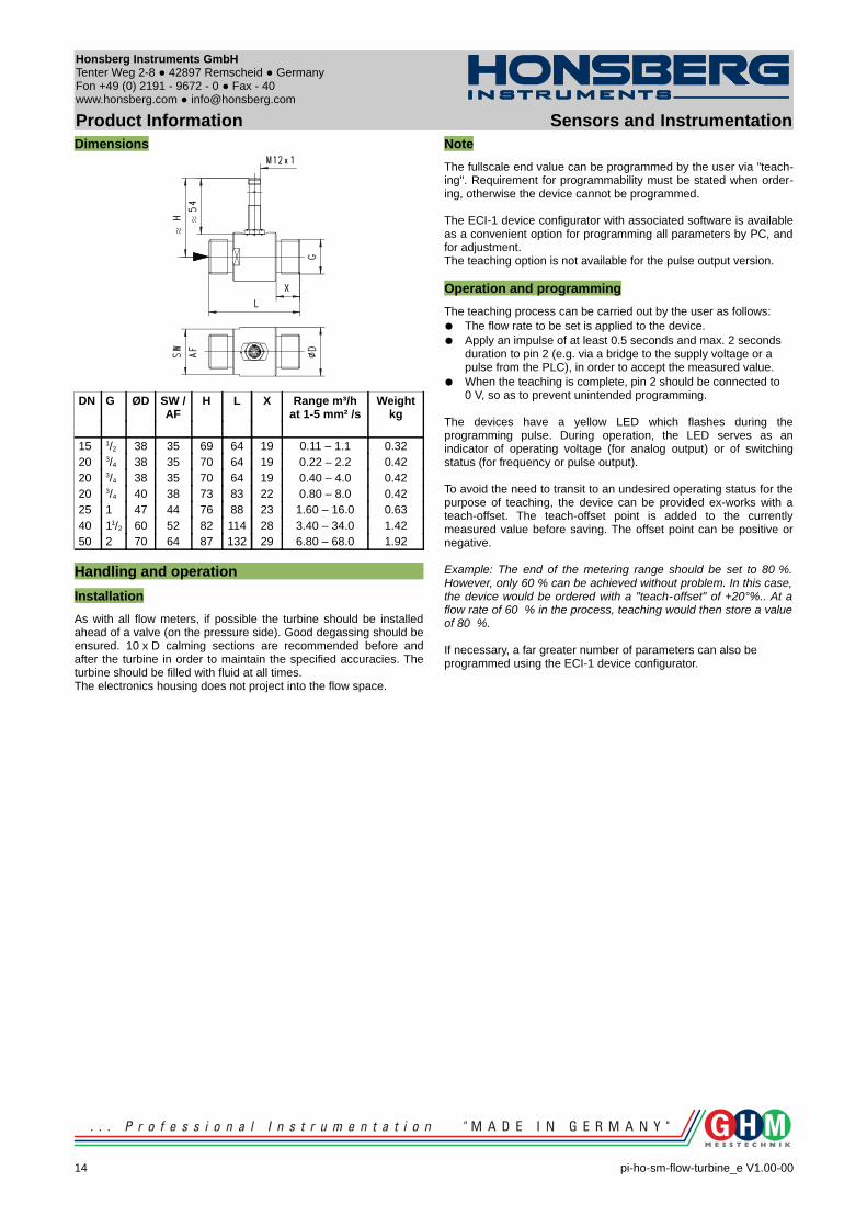
Product Information Sensors and InstrumentationDimensions
DN G ØD SW / AF
H L X Range m³/hat 1-5 mm² /s
Weightkg
15 1/2 38 35 69 64 19 0.11 – 1.1 0.3220 3/4 38 35 70 64 19 0.22 – 2.2 0.4220 3/4 38 35 70 64 19 0.40 – 4.0 0.4220 3/4 40 38 73 83 22 0.80 – 8.0 0.4225 1 47 44 76 88 23 1.60 – 16.0 0.6340 11/2 60 52 82 114 28 3.40 – 34.0 1.4250 2 70 64 87 132 29 6.80 – 68.0 1.92
Handling and operation
Installation
As with all flow meters, if possible the turbine should be installed ahead of a valve (on the pressure side). Good degassing should be ensured. 10 x D calming sections are recommended before and after the turbine in order to maintain the specified accuracies. The turbine should be filled with fluid at all times. The electronics housing does not project into the flow space.
Note
The fullscale end value can be programmed by the user via "teach-ing". Requirement for programmability must be stated when order-ing, otherwise the device cannot be programmed.
The ECI-1 device configurator with associated software is available as a convenient option for programming all parameters by PC, and for adjustment.The teaching option is not available for the pulse output version.
Operation and programming
The teaching process can be carried out by the user as follows: The flow rate to be set is applied to the device. Apply an impulse of at least 0.5 seconds and max. 2 seconds
duration to pin 2 (e.g. via a bridge to the supply voltage or a pulse from the PLC), in order to accept the measured value.
When the teaching is complete, pin 2 should be connected to 0 V, so as to prevent unintended programming.
The devices have a yellow LED which flashes during the programming pulse. During operation, the LED serves as an indicator of operating voltage (for analog output) or of switching status (for frequency or pulse output).
To avoid the need to transit to an undesired operating status for the purpose of teaching, the device can be provided ex-works with a teach-offset. The teach-offset point is added to the currently measured value before saving. The offset point can be positive or negative.
Example: The end of the metering range should be set to 80 %. However, only 60 % can be achieved without problem. In this case, the device would be ordered with a "teach-offset" of +20°%.. At a flow rate of 60 % in the process, teaching would then store a value of 80 %.
If necessary, a far greater number of parameters can also be programmed using the ECI-1 device configurator.
14 pi-ho-sm-flow-turbine_e V1.00-00
Honsberg Instruments GmbH Tenter Weg 2-8 42897 Remscheid Germany Fon +49 (0) 2191 - 9672 - 0 Fax - 40www.honsberg.com [email protected]
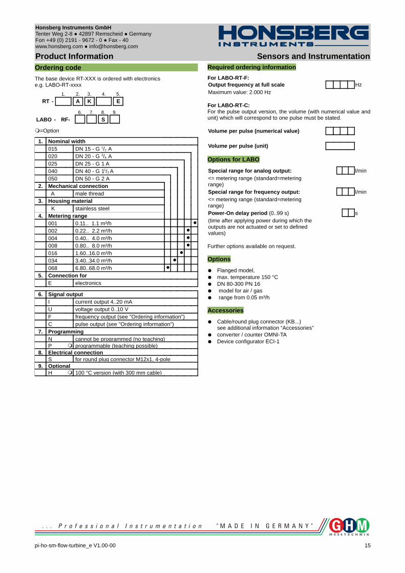
Product Information Sensors and InstrumentationOrdering code
The base device RT-XXX is ordered with electronicse.g. LABO-RT-xxxx
1. 2. 3. 4. 5.
RT - A K E
6. 7. 8. 9.
LABO - RF- S
=Option
1. Nominal width015 DN 15 - G 1/2 A020 DN 20 - G 3/4 A025 DN 25 - G 1 A040 DN 40 - G 11/2 A050 DN 50 - G 2 A
2. Mechanical connection A male thread
3. Housing material K stainless steel
4. Metering range001 0.11.. 1.1 m³/h
002 0.22.. 2.2 m³/h
004 0.40.. 4.0 m³/h
008 0.80.. 8.0 m³/h
016 1.60..16.0 m³/h
034 3.40..34.0 m³/h
068 6.80..68.0 m³/h
5. Connection forE electronics
6. Signal outputI current output 4..20 mAU voltage output 0..10 VF frequency output (see "Ordering information")C pulse output (see "Ordering information")
7. ProgrammingN cannot be programmed (no teaching)P programmable (teaching possible)
8. Electrical connectionS for round plug connector M12x1, 4-pole
9. OptionalH 100 °C version (with 300 mm cable)
Required ordering information
For LABO-RT-F:Output frequency at full scale HzMaximum value: 2.000 Hz
For LABO-RT-C:For the pulse output version, the volume (with numerical value and unit) which will correspond to one pulse must be stated.
Volume per pulse (numerical value)
Volume per pulse (unit)
Options for LABO
Special range for analog output: l/min<= metering range (standard=metering range)Special range for frequency output: l/min<= metering range (standard=metering range)Power-On delay period (0..99 s) s(time after applying power during which the outputs are not actuated or set to defined values)
Further options available on request.
Options
Flanged model, max. temperature 150 °C DN 80-300 PN 16 model for air / gas range from 0.05 m³/h
Accessories
Cable/round plug connector (KB...)see additional information “Accessories”
converter / counter OMNI-TA Device configurator ECI-1
pi-ho-sm-flow-turbine_e V1.00-00
15
Honsberg Instruments GmbH Tenter Weg 2-8 42897 Remscheid Germany Fon +49 (0) 2191 - 9672 - 0 Fax - 40www.honsberg.com [email protected]
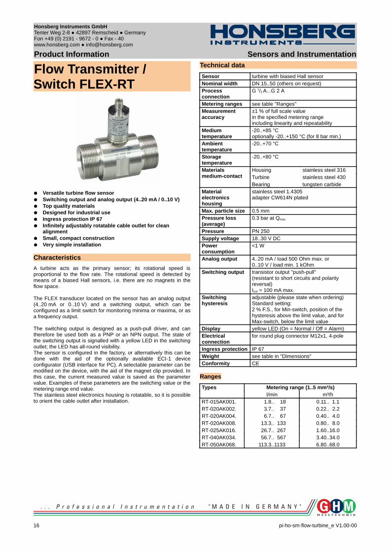
Product Information Sensors and Instrumentation
Flow Transmitter / Switch FLEX-RT
Versatile turbine flow sensor Switching output and analog output (4..20 mA / 0..10 V) Top quality materials Designed for industrial use Ingress protection IP 67 Infinitely adjustably rotatable cable outlet for clean
alignment Small, compact construction Very simple installation
Characteristics
A turbine acts as the primary sensor; its rotational speed is proportional to the flow rate. The rotational speed is detected by means of a biased Hall sensors, i.e. there are no magnets in the flow space.
The FLEX transducer located on the sensor has an analog output (4..20 mA or 0..10 V) and a switching output, which can be configured as a limit switch for monitoring minima or maxima, or as a frequency output.
The switching output is designed as a push-pull driver, and can therefore be used both as a PNP or an NPN output. The state of the switching output is signalled with a yellow LED in the switching outlet; the LED has all-round visibility.The sensor is configured in the factory, or alternatively this can be done with the aid of the optionally available ECI-1 device configurator (USB interface for PC). A selectable parameter can be modified on the device, with the aid of the magnet clip provided. In this case, the current measured value is saved as the parameter value. Examples of these parameters are the switching value or the metering range end value.The stainless steel electronics housing is rotatable, so it is possible to orient the cable outlet after installation.
Technical data
Sensor turbine with biased Hall sensorNominal width DN 15..50 (others on request)Process connection
G 1/2 A...G 2 A
Metering ranges see table "Ranges"Measurement accuracy
±1 % of full scale valuein the specified metering rangeincluding linearity and repeatability
Medium temperature
-20..+85 °Coptionally -20..+150 °C (for 8 bar min.)
Ambient temperature
-20..+70 °C
Storage temperature
-20..+80 °C
Materialsmedium-contact
Housing stainless steel 316Turbine stainless steel 430Bearing tungsten carbide
Materialelectronics housing
stainless steel 1.4305adapter CW614N plated
Max. particle size 0.5 mmPressure loss (average)
0.3 bar at Qmax.
Pressure PN 250Supply voltage 18..30 V DCPower consumption
<1 W
Analog output 4..20 mA / load 500 Ohm max. or 0..10 V / load min. 1 kOhm
Switching output transistor output "push-pull"(resistant to short circuits and polarity reversal)Iout = 100 mA max.
Switching hysteresis
adjustable (please state when ordering)Standard setting:2 % F.S., for Min-switch, position of the hysteresis above the limit value, and for Max-switch, below the limit value
Display yellow LED (On = Normal / Off = Alarm)Electrical connection
for round plug connector M12x1, 4-pole
Ingress protection IP 67Weight see table in "Dimensions"Conformity CE
Ranges
Types Metering range (1..5 mm²/s)l/min m³/h
RT-015AK001. 1.8.. 18 0.11.. 1.1RT-020AK002. 3.7.. 37 0.22.. 2.2RT-020AK004. 6.7.. 67 0.40.. 4.0RT-020AK008. 13.3.. 133 0.80.. 8.0RT-025AK016. 26.7.. 267 1.60..16.0RT-040AK034. 56.7.. 567 3.40..34.0RT-050AK068. 113.3..1133 6.80..68.0
16 pi-ho-sm-flow-turbine_e V1.00-00
Honsberg Instruments GmbH Tenter Weg 2-8 42897 Remscheid Germany Fon +49 (0) 2191 - 9672 - 0 Fax - 40www.honsberg.com [email protected]
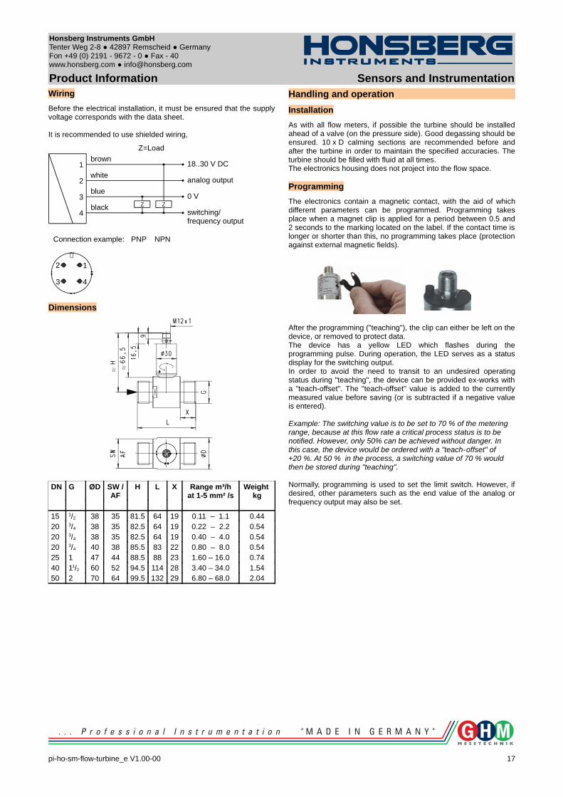
Product Information Sensors and InstrumentationWiring
Before the electrical installation, it must be ensured that the supply voltage corresponds with the data sheet.
It is recommended to use shielded wiring,
Dimensions
DN G ØD SW / AF
H L X Range m³/hat 1-5 mm² /s
Weight kg
15 1/2 38 35 81.5 64 19 0.11 – 1.1 0.4420 3/4 38 35 82.5 64 19 0.22 – 2.2 0.5420 3/4 38 35 82.5 64 19 0.40 – 4.0 0.5420 3/4 40 38 85.5 83 22 0.80 – 8.0 0.5425 1 47 44 88.5 88 23 1.60 – 16.0 0.7440 11/2 60 52 94.5 114 28 3.40 – 34.0 1.5450 2 70 64 99.5 132 29 6.80 – 68.0 2.04
Handling and operation
Installation
As with all flow meters, if possible the turbine should be installed ahead of a valve (on the pressure side). Good degassing should be ensured. 10 x D calming sections are recommended before and after the turbine in order to maintain the specified accuracies. The turbine should be filled with fluid at all times. The electronics housing does not project into the flow space.
Programming
The electronics contain a magnetic contact, with the aid of which different parameters can be programmed. Programming takes place when a magnet clip is applied for a period between 0.5 and 2 seconds to the marking located on the label. If the contact time is longer or shorter than this, no programming takes place (protection against external magnetic fields).
After the programming ("teaching"), the clip can either be left on the device, or removed to protect data. The device has a yellow LED which flashes during the programming pulse. During operation, the LED serves as a status display for the switching output.In order to avoid the need to transit to an undesired operating status during "teaching", the device can be provided ex-works with a "teach-offset". The "teach-offset" value is added to the currently measured value before saving (or is subtracted if a negative value is entered).
Example: The switching value is to be set to 70 % of the metering range, because at this flow rate a critical process status is to be notified. However, only 50% can be achieved without danger. In this case, the device would be ordered with a "teach-offset" of +20 %. At 50 % in the process, a switching value of 70 % would then be stored during "teaching".
Normally, programming is used to set the limit switch. However, if desired, other parameters such as the end value of the analog or frequency output may also be set.
pi-ho-sm-flow-turbine_e V1.00-00
17
Z Z
1
2
3
4
brown
white
blue
black
18..30 V DC
analog output
0 V
switching/frequency output
PNP NPNConnection example:
1
43
2
Z=Load

Honsberg Instruments GmbH Tenter Weg 2-8 42897 Remscheid Germany Fon +49 (0) 2191 - 9672 - 0 Fax - 40www.honsberg.com [email protected]
Product Information Sensors and InstrumentationThe limit switch can be used to monitor minima or maxima.
With a minimum-switch, falling below the limit value causes a switchover to the alarm state. Return to the normal state occurs when the limit value plus the set hysteresis is again exceeded.
With a maximum-switch, exceeding the limit value causes a switchover to the alarm state. Return to the normal state occurs when the measured value once more falls below the limit value minus the set hysteresis.
A switchover delay time (tDS) can be applied to the switchover to the alarm state. Equally, one switch-back delay time (tDR) of several can be applied to switching back to the normal state.
In the normal state the integrated LED is on, in the alarm state it is off, and this corresponds to its status when there is no supply voltage.In the non-inverted (standard) model, while in the normal state the switching output is at the level of the supply voltage; in the alarm state it is at 0 V, so that a wire break would also display as an alarm state at the signal receiver. Optionally, an inverted switching output can also be provided, i.e. in the normal state the output is at 0 V, and in the alarm state it is at the level of the supply voltage.
A Power-On delay function (ordered as a separate option) makes it possible to maintain the switching output in the normal state for a defined period after application of the supply voltage.
18 pi-ho-sm-flow-turbine_e V1.00-00
Min
Min+Hyst
t
T
Max-Hyst
t
T
Max
Max-Hyst
t
T
Max
tDS
tDR
t
non-inverted output
inverted output
Honsberg Instruments GmbH Tenter Weg 2-8 42897 Remscheid Germany Fon +49 (0) 2191 - 9672 - 0 Fax - 40www.honsberg.com [email protected]
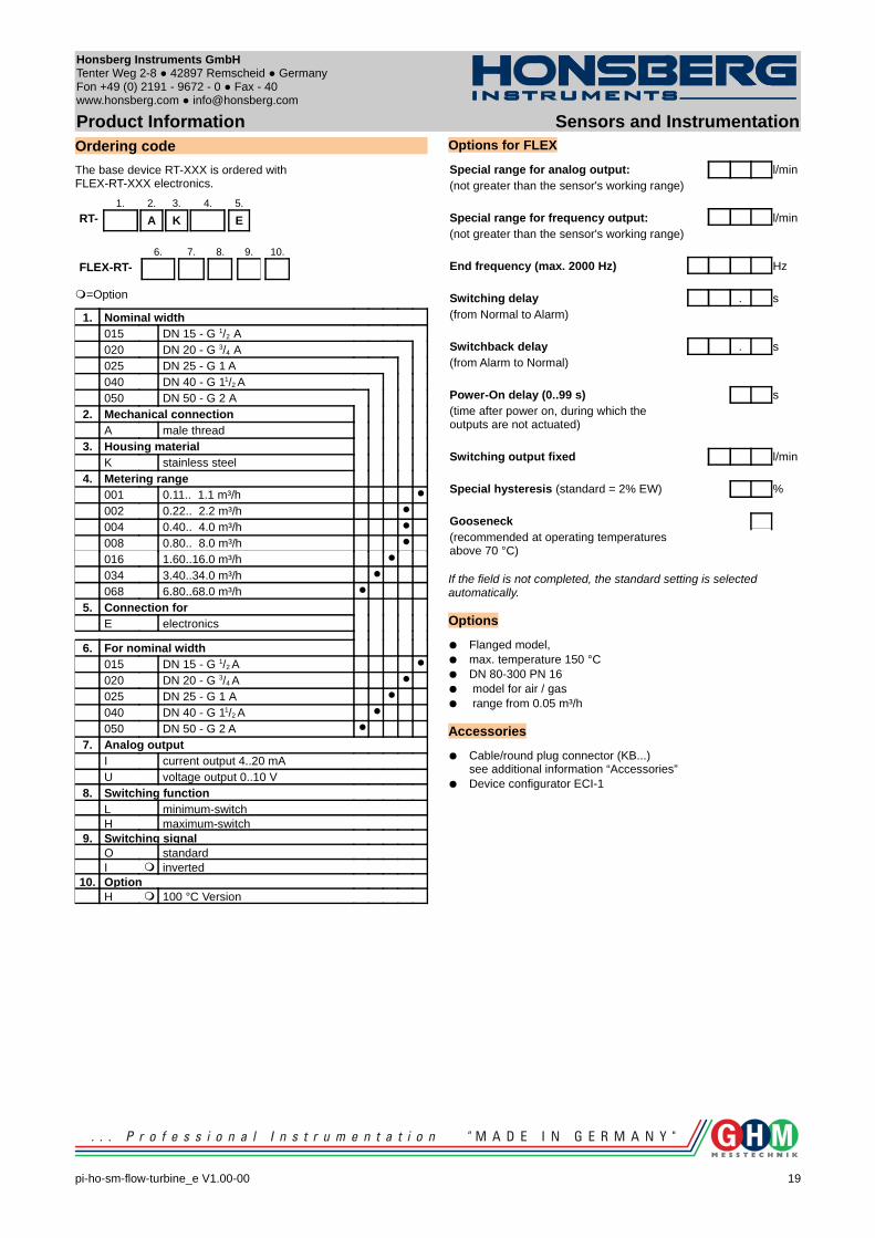
Product Information Sensors and InstrumentationOrdering code
The base device RT-XXX is ordered with FLEX-RT-XXX electronics.
1. 2. 3. 4. 5.
RT- A K E
6. 7. 8. 9. 10.
FLEX-RT-
=Option
1. Nominal width015 DN 15 - G 1/2 A020 DN 20 - G 3/4 A025 DN 25 - G 1 A040 DN 40 - G 11/2 A050 DN 50 - G 2 A
2. Mechanical connectionA male thread
3. Housing materialK stainless steel
4. Metering range001 0.11.. 1.1 m³/h
002 0.22.. 2.2 m³/h
004 0.40.. 4.0 m³/h
008 0.80.. 8.0 m³/h
016 1.60..16.0 m³/h
034 3.40..34.0 m³/h
068 6.80..68.0 m³/h
5. Connection forE electronics
6. For nominal width015 DN 15 - G 1/2 A
020 DN 20 - G 3/4 A
025 DN 25 - G 1 A
040 DN 40 - G 11/2 A
050 DN 50 - G 2 A
7. Analog outputI current output 4..20 mAU voltage output 0..10 V
8. Switching function L minimum-switchH maximum-switch
9. Switching signalO standardI inverted
10. OptionH 100 °C Version
Options for FLEX
Special range for analog output: l/min(not greater than the sensor's working range)
Special range for frequency output: l/min(not greater than the sensor's working range)
End frequency (max. 2000 Hz) Hz
Switching delay . s(from Normal to Alarm)
Switchback delay . s(from Alarm to Normal)
Power-On delay (0..99 s) s(time after power on, during which the outputs are not actuated)
Switching output fixed l/min
Special hysteresis (standard = 2% EW) %
Gooseneck(recommended at operating temperatures above 70 °C)
If the field is not completed, the standard setting is selected automatically. Options
Flanged model, max. temperature 150 °C DN 80-300 PN 16 model for air / gas range from 0.05 m³/h
Accessories
Cable/round plug connector (KB...)see additional information “Accessories”
Device configurator ECI-1
pi-ho-sm-flow-turbine_e V1.00-00
19
Honsberg Instruments GmbH Tenter Weg 2-8 42897 Remscheid Germany Fon +49 (0) 2191 - 9672 - 0 Fax - 40www.honsberg.com [email protected]
Product Information Sensors and Instrumentation
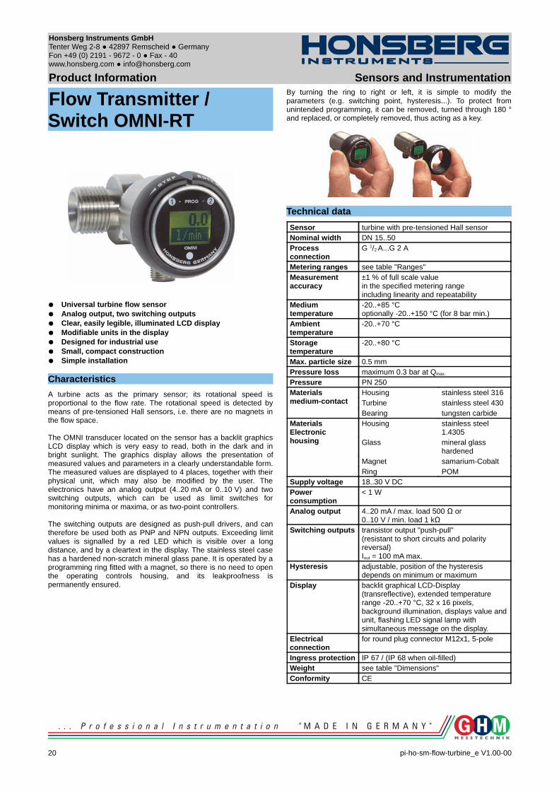
Flow Transmitter / Switch OMNI-RT
Universal turbine flow sensor Analog output, two switching outputs Clear, easily legible, illuminated LCD display Modifiable units in the display Designed for industrial use Small, compact construction Simple installation
Characteristics
A turbine acts as the primary sensor; its rotational speed is proportional to the flow rate. The rotational speed is detected by means of pre-tensioned Hall sensors, i.e. there are no magnets in the flow space.
The OMNI transducer located on the sensor has a backlit graphics LCD display which is very easy to read, both in the dark and in bright sunlight. The graphics display allows the presentation of measured values and parameters in a clearly understandable form. The measured values are displayed to 4 places, together with their physical unit, which may also be modified by the user. The electronics have an analog output (4..20 mA or 0..10 V) and two switching outputs, which can be used as limit switches for monitoring minima or maxima, or as two-point controllers.
The switching outputs are designed as push-pull drivers, and can therefore be used both as PNP and NPN outputs. Exceeding limit values is signalled by a red LED which is visible over a long distance, and by a cleartext in the display. The stainless steel case has a hardened non-scratch mineral glass pane. It is operated by a programming ring fitted with a magnet, so there is no need to open the operating controls housing, and its leakproofness is permanently ensured.
By turning the ring to right or left, it is simple to modify the parameters (e.g. switching point, hysteresis...). To protect from unintended programming, it can be removed, turned through 180 ° and replaced, or completely removed, thus acting as a key.
Technical data
Sensor turbine with pre-tensioned Hall sensorNominal width DN 15..50Process connection
G 1/2 A...G 2 A
Metering ranges see table "Ranges"Measurement accuracy
±1 % of full scale valuein the specified metering rangeincluding linearity and repeatability
Medium temperature
-20..+85 °Coptionally -20..+150 °C (for 8 bar min.)
Ambienttemperature
-20..+70 °C
Storage temperature
-20..+80 °C
Max. particle size 0.5 mmPressure loss maximum 0.3 bar at Qmax.
Pressure PN 250Materialsmedium-contact
Housing stainless steel 316Turbine stainless steel 430Bearing tungsten carbide
MaterialsElectronic housing
Housing stainless steel 1.4305
Glass mineral glass hardened
Magnet samarium-CobaltRing POM
Supply voltage 18..30 V DCPower consumption
< 1 W
Analog output 4..20 mA / max. load 500 Ω or0..10 V / min. load 1 kΩ
Switching outputs transistor output "push-pull"(resistant to short circuits and polarity reversal)Iout = 100 mA max.
Hysteresis adjustable, position of the hysteresis depends on minimum or maximum
Display backlit graphical LCD-Display (transreflective), extended temperature range -20..+70 °C, 32 x 16 pixels, background illumination, displays value and unit, flashing LED signal lamp with simultaneous message on the display.
Electrical connection
for round plug connector M12x1, 5-pole
Ingress protection IP 67 / (IP 68 when oil-filled)Weight see table "Dimensions"Conformity CE
20 pi-ho-sm-flow-turbine_e V1.00-00
Honsberg Instruments GmbH Tenter Weg 2-8 42897 Remscheid Germany Fon +49 (0) 2191 - 9672 - 0 Fax - 40www.honsberg.com [email protected]
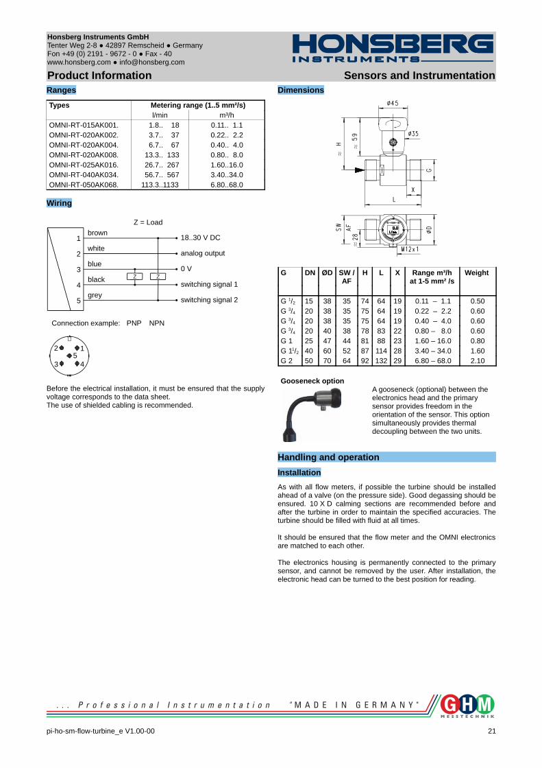
Product Information Sensors and InstrumentationRanges
Types Metering range (1..5 mm²/s)l/min m³/h
OMNI-RT-015AK001. 1.8.. 18 0.11.. 1.1OMNI-RT-020AK002. 3.7.. 37 0.22.. 2.2OMNI-RT-020AK004. 6.7.. 67 0.40.. 4.0OMNI-RT-020AK008. 13.3.. 133 0.80.. 8.0OMNI-RT-025AK016. 26.7.. 267 1.60..16.0OMNI-RT-040AK034. 56.7.. 567 3.40..34.0OMNI-RT-050AK068. 113.3..1133 6.80..68.0
Wiring
Before the electrical installation, it must be ensured that the supply voltage corresponds to the data sheet.The use of shielded cabling is recommended.
Dimensions
G DN ØD SW / AF
H L X Range m³/hat 1-5 mm² /s
Weight
G 1/2 15 38 35 74 64 19 0.11 – 1.1 0.50G 3/4 20 38 35 75 64 19 0.22 – 2.2 0.60G 3/4 20 38 35 75 64 19 0.40 – 4.0 0.60G 3/4 20 40 38 78 83 22 0.80 – 8.0 0.60G 1 25 47 44 81 88 23 1.60 – 16.0 0.80G 11/2 40 60 52 87 114 28 3.40 – 34.0 1.60G 2 50 70 64 92 132 29 6.80 – 68.0 2.10
Gooseneck optionA gooseneck (optional) between the electronics head and the primary sensor provides freedom in the orientation of the sensor. This option simultaneously provides thermal decoupling between the two units.
Handling and operation
Installation
As with all flow meters, if possible the turbine should be installed ahead of a valve (on the pressure side). Good degassing should be ensured. 10 X D calming sections are recommended before and after the turbine in order to maintain the specified accuracies. The turbine should be filled with fluid at all times.
It should be ensured that the flow meter and the OMNI electronics are matched to each other.
The electronics housing is permanently connected to the primary sensor, and cannot be removed by the user. After installation, the electronic head can be turned to the best position for reading.
pi-ho-sm-flow-turbine_e V1.00-00
21
Z Z
1
2
3
4
5
brown
white
blue
black
grey
18..30 V DC
analog output
0 V
switching signal 1
switching signal 2
PNP NPNConnection example:
1
43
25
Z = Load
Honsberg Instruments GmbH Tenter Weg 2-8 42897 Remscheid Germany Fon +49 (0) 2191 - 9672 - 0 Fax - 40www.honsberg.com [email protected]
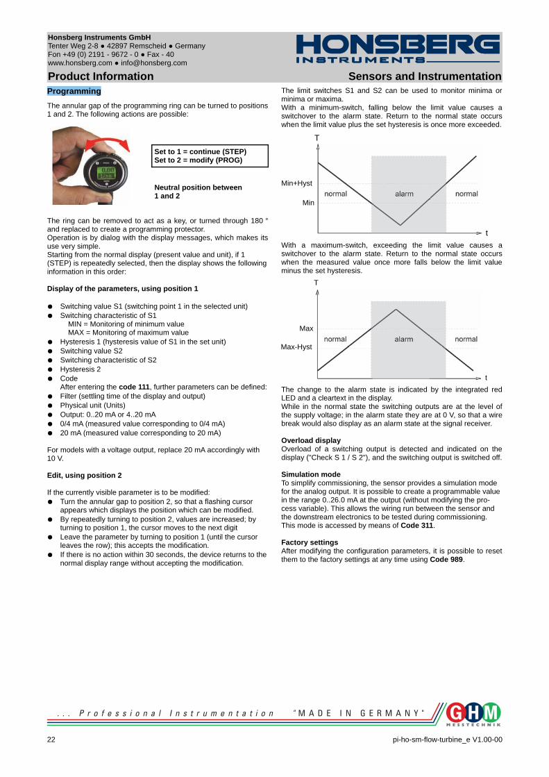
Product Information Sensors and InstrumentationProgramming
The annular gap of the programming ring can be turned to positions 1 and 2. The following actions are possible:
Set to 1 = continue (STEP)Set to 2 = modify (PROG)
Neutral position between1 and 2
The ring can be removed to act as a key, or turned through 180 ° and replaced to create a programming protector. Operation is by dialog with the display messages, which makes its use very simple.Starting from the normal display (present value and unit), if 1 (STEP) is repeatedly selected, then the display shows the following information in this order:
Display of the parameters, using position 1
Switching value S1 (switching point 1 in the selected unit) Switching characteristic of S1
MIN = Monitoring of minimum valueMAX = Monitoring of maximum value
Hysteresis 1 (hysteresis value of S1 in the set unit) Switching value S2 Switching characteristic of S2 Hysteresis 2 Code
After entering the code 111, further parameters can be defined: Filter (settling time of the display and output) Physical unit (Units) Output: 0..20 mA or 4..20 mA 0/4 mA (measured value corresponding to 0/4 mA) 20 mA (measured value corresponding to 20 mA)
For models with a voltage output, replace 20 mA accordingly with 10 V.
Edit, using position 2
If the currently visible parameter is to be modified: Turn the annular gap to position 2, so that a flashing cursor
appears which displays the position which can be modified. By repeatedly turning to position 2, values are increased; by
turning to position 1, the cursor moves to the next digit Leave the parameter by turning to position 1 (until the cursor
leaves the row); this accepts the modification. If there is no action within 30 seconds, the device returns to the
normal display range without accepting the modification.
The limit switches S1 and S2 can be used to monitor minima or minima or maxima.With a minimum-switch, falling below the limit value causes a switchover to the alarm state. Return to the normal state occurs when the limit value plus the set hysteresis is once more exceeded.
With a maximum-switch, exceeding the limit value causes a switchover to the alarm state. Return to the normal state occurs when the measured value once more falls below the limit value minus the set hysteresis.
The change to the alarm state is indicated by the integrated red LED and a cleartext in the display.While in the normal state the switching outputs are at the level of the supply voltage; in the alarm state they are at 0 V, so that a wire break would also display as an alarm state at the signal receiver.
Overload displayOverload of a switching output is detected and indicated on the display ("Check S 1 / S 2"), and the switching output is switched off.
Simulation modeTo simplify commissioning, the sensor provides a simulation mode for the analog output. It is possible to create a programmable value in the range 0..26.0 mA at the output (without modifying the pro-cess variable). This allows the wiring run between the sensor and the downstream electronics to be tested during commissioning. This mode is accessed by means of Code 311.
Factory settingsAfter modifying the configuration parameters, it is possible to reset them to the factory settings at any time using Code 989.
22 pi-ho-sm-flow-turbine_e V1.00-00
Max-Hyst
t
T
Max
Min
Min+Hyst
t
T

Honsberg Instruments GmbH Tenter Weg 2-8 42897 Remscheid Germany Fon +49 (0) 2191 - 9672 - 0 Fax - 40www.honsberg.com [email protected]
Product Information Sensors and InstrumentationOrdering code
The basic device is ordered e.g. RT-xxx with electronics e.g. OMNI-RT-xxxx
1. 2. 3. 4. 5. 6.
RT- A K E
7. 8. 9. 10.
OMNI-RT- S
=Option
1. Nominal width015 DN 15 - G 1/2 A020 DN 20 - G 3/4 A025 DN 25 - G 1 A040 DN 40 - G 11/2 A050 DN 50 - G 2 A
2. Mechanical connectionA male thread
3. Housing materialK stainless steel
4. Metering range001 0.11.. 1.1 m³/h
002 0.22.. 2.2 m³/h
004 0.40.. 4.0 m³/h
008 0.80.. 8.0 m³/h
016 1.60..16.0 m³/h
034 3.40..34.0 m³/h
068 6.80..68.0 m³/h
5. Connection forE electronics
6. OptionH high temperature model
7. For nominal width015 DN 15 - G 1/2 A
020 DN 20 - G 3/4 A
025 DN 25 - G 1 A
040 DN 40 - G 11/2 A
050 DN 50 - G 2 A
8. Analog outputI current output 0/4..20 mAU voltage output 0/2..10 V
9. Electrical connectionS for round plug connector M12x1, 5-pole
10. High temperatureH 150 °C version
O tropical modeloil-filled version for heavy duty or external use
Accessories
Cable/round plug connector (KB...)see additional information “Accessories”
Device configurator ECI-1
pi-ho-sm-flow-turbine_e V1.00-00
23

Honsberg Instruments GmbH Tenter Weg 2-8 42897 Remscheid Germany Fon +49 (0) 2191 - 9672 - 0 Fax - 40www.honsberg.com [email protected]
Product Information Sensors and Instrumentation
OMNI-C-RT Counter
Simple totalisation Simple filling counter with programmable end signal Control switchover at present value Automatic, dynamic change of displayed
unit and decimal places in the graphics display Antivalent outputs Simple guided menu via graphics display Very compact dimensions Full metal housing with high protection class Rotatable head for optimum reading direction
Characteristics
A turbine acts as the primary sensor; its rotational speed is proportional to the flow rate. The rotational speed is detected by means of biased Hall sensors, i.e. there are no magnets in the flow space.
The totaliser of the OMNI flow rate system enables a totalisation or measurement of consumption for all HONSBERG device families (for fluids and gases) with which the OMNI system is compatible; this is independent of the input signal, pulse or analog input, and of the measurement process.
Simple filling control is also possible. Here, the counter can be set to count upwards or downwards.When the preset point is reached, a switching signal is emitted which is available in antivalent form to two outputs.Resetting can be carried out by means of a signal input or also by a programming ring.
The state of the counter is indicated in an LCD display with only four digits. Here, the number of decimal places and the unit displayed is continuously matched to the current state of the counter. In this case, the smallest value which can be displayed is 0.001 ml (= 1 µl), and the largest is 9999 m³. The counter therefore has 13 places, of which the four most significant are displayed at any one time. The display resolution at all times is therefore at least 1 per thousand of the displayed value, or better, and this generally exceeds the accuracy of the connected flow transmitter. The non-displayed digits of the counter are in that case irrelevant to the accuracy of the measurement.
The automatic dynamic changeover of units in the display in relation to the state of the counter makes the value easy to read in spite of a display with only four digits. In addition, user configuration of the counter is unnecessary.
In addition to the totalised value, the present flow rate can be displayed. The stainless steel housing has a hardened non-scratch mineral glass pane. It is operated by a programming ring fitted with a magnet, so there is no need to open the operating controls housing, and its leakproofness is permanently ensured.By turning the ring to right or left, it is simple to modify the
parameters (e.g. switching point, hysteresis...). To protect from unintended programming, it can be removed, turned through 180 ° and replaced, or completely removed, thus acting as a key.
Technical data
Sensor turbine with biased Hall sensorNominal width DN 15..50Process connection
G 1/2 A...G 2 A
Metering ranges see table "Ranges"Measurement accuracy
±1 % of full scale valuein the specified metering rangeincluding linearity and repeatability.
Medium temperature
-20..+85 °Coptionally -20..+150 °C (for 8 bar min.)
Ambienttemperature
-20..+70 °C
Storage temperature
-20..+80 °C
Max. particle size 0.5 mmPressure loss maximum 0.3 bar at Qmax.
Pressure PN 250Materialsmedium-contact
Housing stainless steel 316Turbine stainless steel 430Bearing tungsten carbide
Materialselectronic housing
Housing stainless steel 1.4305
Glass mineral glass hardened
Magnet samarium-CobaltRing POM
Counter range 0.000 ml to 9999 m³with automatic setting of the decimal places and of the applicable unit.
Switching signal outputs(Pin 4 + 5)
2 x push-pull output, max. 100 mA, resistant to short circuits, and reversal polarity protectedantivalent states, configurable on the device as a wipe or edge signal
Counter reset signal (Pin 2)
input 18..30 V resistant to short circuits and polarity reversalPIN 2, wipe signal, pos. or neg. , edge pos. or neg., can be selected on site
Counting input (normally not directly accessible from the device) Frequency input 0..10 kHzanalog input 0/4..20 mAanalog input 0..10 V
Supply voltage 18..30 VDC Power consumption
< 1 W
Display backlit graphical LCD-Display (transreflective), extended temperature range -20..+70 °C, 32 x 16 pixels, background illumination, displays value and unit, flashing LED signal lamp with simultaneous message on the display.
24 pi-ho-sm-flow-turbine_e V1.00-00
Honsberg Instruments GmbH Tenter Weg 2-8 42897 Remscheid Germany Fon +49 (0) 2191 - 9672 - 0 Fax - 40www.honsberg.com [email protected]
Product Information Sensors and InstrumentationElectrical connection
for round plug connector M12x1, 5-pole
Ingress protection IP 67 / (IP 68 when oil-filled)Weight see table "Dimensions"Conformity CE
Ranges
Types Metering range (1..5 mm²/s)l/min m³/h
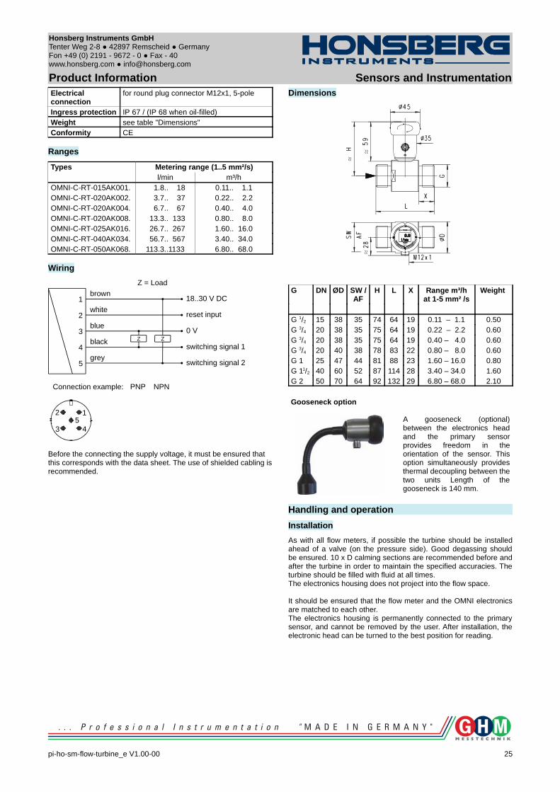
OMNI-C-RT-015AK001. 1.8.. 18 0.11.. 1.1OMNI-C-RT-020AK002. 3.7.. 37 0.22.. 2.2OMNI-C-RT-020AK004. 6.7.. 67 0.40.. 4.0OMNI-C-RT-020AK008. 13.3.. 133 0.80.. 8.0OMNI-C-RT-025AK016. 26.7.. 267 1.60.. 16.0OMNI-C-RT-040AK034. 56.7.. 567 3.40.. 34.0OMNI-C-RT-050AK068. 113.3..1133 6.80.. 68.0
Wiring
Before the connecting the supply voltage, it must be ensured that this corresponds with the data sheet. The use of shielded cabling is recommended.
Dimensions
G DN ØD SW / AF
H L X Range m³/hat 1-5 mm² /s
Weight
G 1/2 15 38 35 74 64 19 0.11 – 1.1 0.50G 3/4 20 38 35 75 64 19 0.22 – 2.2 0.60G 3/4 20 38 35 75 64 19 0.40 – 4.0 0.60G 3/4 20 40 38 78 83 22 0.80 – 8.0 0.60G 1 25 47 44 81 88 23 1.60 – 16.0 0.80G 11/2 40 60 52 87 114 28 3.40 – 34.0 1.60G 2 50 70 64 92 132 29 6.80 – 68.0 2.10
Gooseneck option
A gooseneck (optional) between the electronics head and the primary sensor provides freedom in the orientation of the sensor. This option simultaneously provides thermal decoupling between the two units Length of the gooseneck is 140 mm.
Handling and operation
Installation
As with all flow meters, if possible the turbine should be installed ahead of a valve (on the pressure side). Good degassing should be ensured. 10 x D calming sections are recommended before and after the turbine in order to maintain the specified accuracies. The turbine should be filled with fluid at all times. The electronics housing does not project into the flow space.
It should be ensured that the flow meter and the OMNI electronics are matched to each other.The electronics housing is permanently connected to the primary sensor, and cannot be removed by the user. After installation, the electronic head can be turned to the best position for reading.
pi-ho-sm-flow-turbine_e V1.00-00
25
Z Z
1
2
3
4
5
brown
white
blue
black
grey
18..30 V DC
reset input
0 V
switching signal 1
switching signal 2
PNP NPNConnection example:
1
43
25
Z = Load
Honsberg Instruments GmbH Tenter Weg 2-8 42897 Remscheid Germany Fon +49 (0) 2191 - 9672 - 0 Fax - 40www.honsberg.com [email protected]
Product Information Sensors and InstrumentationProgramming
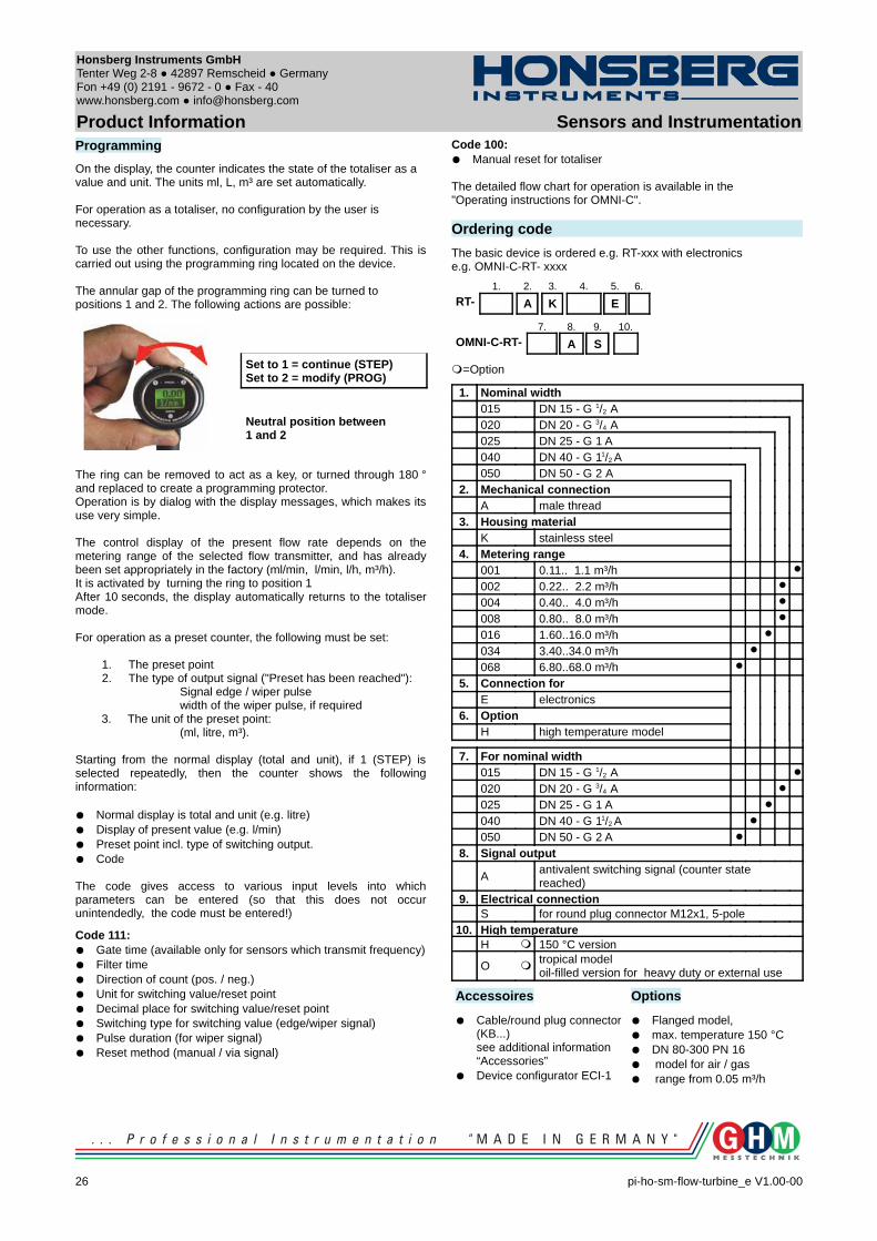
On the display, the counter indicates the state of the totaliser as a value and unit. The units ml, L, m³ are set automatically.
For operation as a totaliser, no configuration by the user is necessary.
To use the other functions, configuration may be required. This is carried out using the programming ring located on the device.
The annular gap of the programming ring can be turned to positions 1 and 2. The following actions are possible:
Set to 1 = continue (STEP)Set to 2 = modify (PROG)
Neutral position between1 and 2
The ring can be removed to act as a key, or turned through 180 ° and replaced to create a programming protector.Operation is by dialog with the display messages, which makes its use very simple.
The control display of the present flow rate depends on the metering range of the selected flow transmitter, and has already been set appropriately in the factory (ml/min, l/min, l/h, m³/h).It is activated by turning the ring to position 1After 10 seconds, the display automatically returns to the totaliser mode.
For operation as a preset counter, the following must be set:
1. The preset point2. The type of output signal ("Preset has been reached"):
Signal edge / wiper pulse width of the wiper pulse, if required
3. The unit of the preset point: (ml, litre, m³).
Starting from the normal display (total and unit), if 1 (STEP) is selected repeatedly, then the counter shows the following information:
Normal display is total and unit (e.g. litre) Display of present value (e.g. l/min) Preset point incl. type of switching output. Code
The code gives access to various input levels into which parameters can be entered (so that this does not occur unintendedly, the code must be entered!)
Code 111: Gate time (available only for sensors which transmit frequency) Filter time Direction of count (pos. / neg.) Unit for switching value/reset point Decimal place for switching value/reset point Switching type for switching value (edge/wiper signal) Pulse duration (for wiper signal) Reset method (manual / via signal)
Code 100: Manual reset for totaliser
The detailed flow chart for operation is available in the "Operating instructions for OMNI-C".
Ordering code
The basic device is ordered e.g. RT-xxx with electronics e.g. OMNI-C-RT- xxxx
1. 2. 3. 4. 5. 6.
RT- A K E
7. 8. 9. 10.
OMNI-C-RT- A S
=Option
1. Nominal width015 DN 15 - G 1/2 A020 DN 20 - G 3/4 A025 DN 25 - G 1 A040 DN 40 - G 11/2 A050 DN 50 - G 2 A
2. Mechanical connectionA male thread
3. Housing materialK stainless steel
4. Metering range001 0.11.. 1.1 m³/h
002 0.22.. 2.2 m³/h
004 0.40.. 4.0 m³/h
008 0.80.. 8.0 m³/h
016 1.60..16.0 m³/h
034 3.40..34.0 m³/h
068 6.80..68.0 m³/h
5. Connection forE electronics
6. OptionH high temperature model
7. For nominal width015 DN 15 - G 1/2 A
020 DN 20 - G 3/4 A
025 DN 25 - G 1 A
040 DN 40 - G 11/2 A
050 DN 50 - G 2 A
8. Signal output
Aantivalent switching signal (counter state reached)
9. Electrical connectionS for round plug connector M12x1, 5-pole
10. High temperatureH 150 °C version
O tropical modeloil-filled version for heavy duty or external use
Accessoires
Cable/round plug connector (KB...)see additional information “Accessories”
Device configurator ECI-1
Options
Flanged model, max. temperature 150 °C DN 80-300 PN 16 model for air / gas range from 0.05 m³/h
26 pi-ho-sm-flow-turbine_e V1.00-00
Honsberg Instruments GmbH Tenter Weg 2-8 42897 Remscheid Germany Fon +49 (0) 2191 - 9672 - 0 Fax - 40www.honsberg.com [email protected]
Product Information Sensors and Instrumentation
Device ConfiguratorECI-1
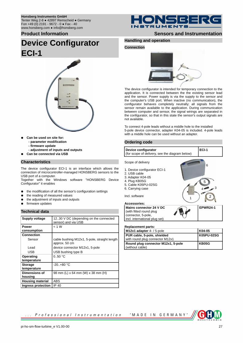
Can be used on site for: - parameter modification - firmware update - adjustment of inputs and outputs Can be connected via USB
Characteristics
The device configurator ECI-1 is an interface which allows the connection of microcontroller-managed HONSBERG sensors to the USB port of a computer. Together with the Windows software "HONSBERG Device Configurator" it enables
the modification of all the sensor's configuration settings the reading of measured values the adjustment of inputs and outputs firmware updates
Technical data
Supply voltage 12..30 V DC (depending on the connected sensor) and via USB
Power consumption
< 1 W
ConnectionSensor cable bushing M12x1, 5-pole, straight length
approx. 50 cmLead device connector M12x1, 5-poleUSB USB bushing type B
Operating temperature
0..50 °C
Storage temperature
-20..+80 °C
Dimensions of housing
98 mm (L) x 64 mm (W) x 38 mm (H)
Housing material ABSIngress protection IP 40
Handling and operation
Connection
The device configurator is intended for temporary connection to the application. It is connected between the the existing sensor lead and the sensor. Power supply is via the supply to the sensor and the computer's USB port. When inactive (no communication), the configurator behaves completely neutrally; all signals from the sensor remain available to the application. During communication between computer and sensor, the signal wirings are separated in the configurator, so that in this state the sensor's output signals are not available.
To connect 4-pole leads without a middle hole to the installed 5-pole device connector, adapter K04-05 is included. 4-pole leads with a middle hole can be used without an adapter.
Ordering code
Device configurator (for scope of delivery, see the diagram below)
ECI-1
Scope of delivery
1. Device configurator ECI-12. USB cable3. Adapter K04-054. Plug KB05G 5. Cable K05PU-02SG6. Carrying case
Incl. software
Accessories:Mains connector 24 V DC(with fitted round plugconnector, 5-pole, incl. international plug set)
EPWR24-1
Replacement parts:M12x1 adapter 4- / 5-pole K04-05PUR cable, 5-pole, shieldedwith round plug connector M12x1
K05PU-02SG
Round plug connector M12x1, 5-pole(without cable)
KB05G
pi-ho-sm-flow-turbine_e V1.00-00
27
1 2
34
5
6

GHM Messtechnik GmbHHans-Sachs-Str. 26 93128 Regenstauf Germany Fon +49 (0) 9402 - 9383 - 0 Fax - 33www.ghm-messtechnik.de [email protected]
Product Information Sensors and Instrumentation
OptionsLABO transmitter - Temperature up to 150 °C
All LABO transmitters can be used with electronics positioned in a separate area with media temperatures up to 150 °C.
OMNI - Tropical model
This OMNI electronic option should be used where temperatures change quickly, or for external installations (the device is filled with oil, and thus prevents condensate formation in the electronics housing, even under adverse circumstances)
28 pi-ho-sm-flow-turbine_e V1.00-00
GHM Messtechnik GmbHHans-Sachs-Str. 26 93128 Regenstauf Germany Fon +49 (0) 9402 - 9383 - 0 Fax - 33www.ghm-messtechnik.de [email protected]
Product Information Sensors and Instrumentation
AccessoriesFilter
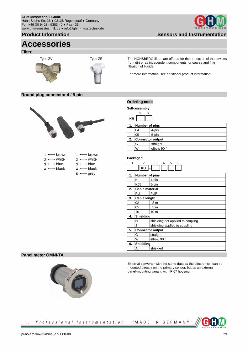
Type ZV Type ZE The HONSBERG filters are offered for the protection of the devicesfrom dirt or as independent components for coarse and finefiltration of liquids.
For more information, see additional product information.
Round plug connector 4 / 5-pin
Ordering code
Self-assembly
1. 2.
KB
1. Number of pins04 4-pin05 5-pin
2. Connector outputG straightW elbow 90 °
Packaged
1. 2. 3. 4. 5. 6.
PU -
1. Number of pinsK 4-pinK05 5-pin
2. Cable materialPU PUR
3. Cable length02 2 m05 5 m10 10 m
4. ShieldingN shielding not applied to couplingS shielding applied to coupling
5. Connector outputG straightW elbow 90 °
6. ShieldingA shielded
Panel meter OMNI-TA
External converter with the same data as the electronics; can be mounted directly on the primary sensor, but as an external panel-mounting variant with IP 67 housing.
pi-ho-sm-flow-turbine_e V1.00-00
29
3 blue2 white1 brown
4 black3 blue2 white1 brown
4 black5 grey
GHM Messtechnik GmbHHans-Sachs-Str. 26 93128 Regenstauf Germany Fon +49 (0) 9402 - 9383 - 0 Fax - 33www.ghm-messtechnik.de [email protected]
Product Information Sensors and Instrumentation
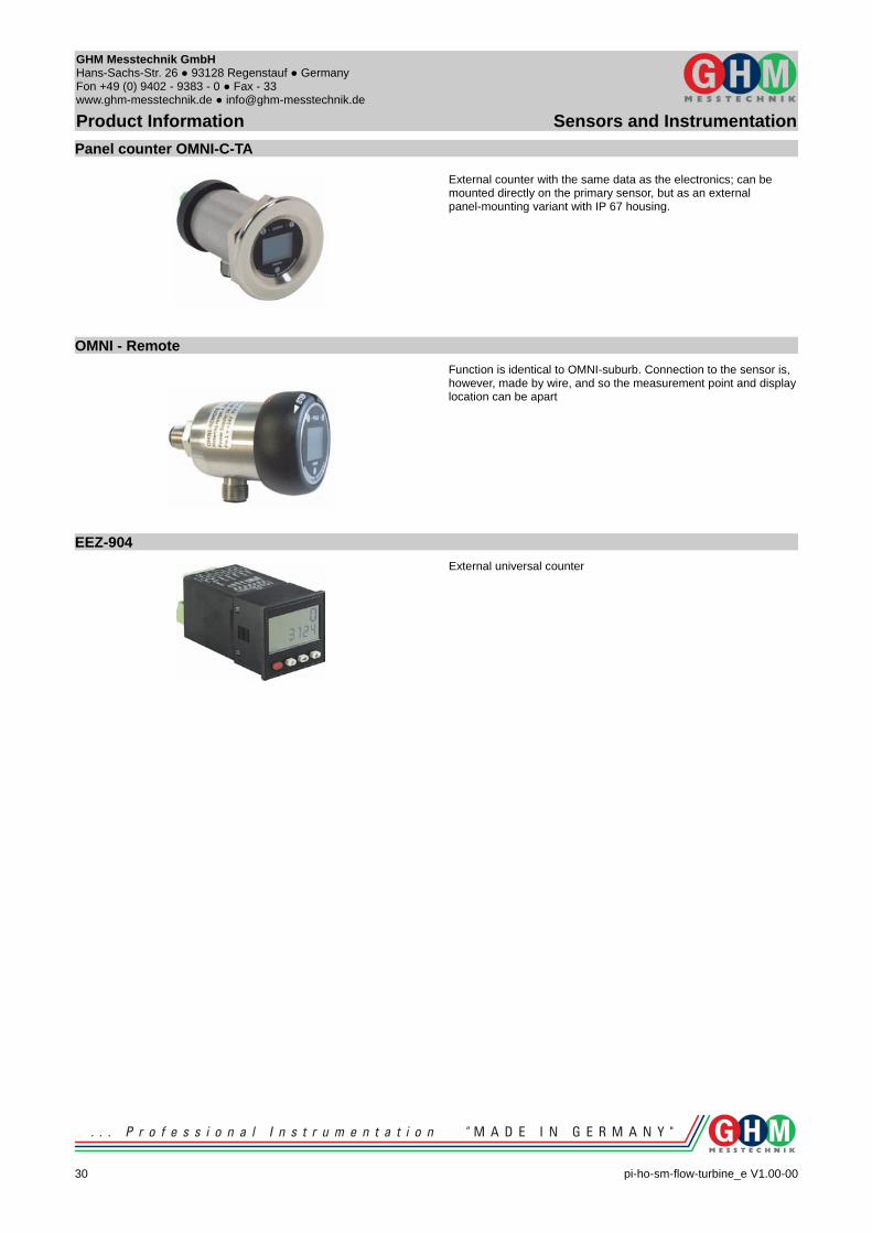
Panel counter OMNI-C-TA
External counter with the same data as the electronics; can be mounted directly on the primary sensor, but as an external panel-mounting variant with IP 67 housing.
OMNI - Remote
Function is identical to OMNI-suburb. Connection to the sensor is, however, made by wire, and so the measurement point and display location can be apart
EEZ-904
External universal counter
30 pi-ho-sm-flow-turbine_e V1.00-00

GHM Messtechnik GmbHHans-Sachs-Str. 26 93128 Regenstauf Germany Fon +49 (0) 9402 - 9383 - 0 Fax - 33www.ghm-messtechnik.de [email protected]
Product Information Sensors and Instrumentation
pi-ho-sm-flow-turbine_e V1.00-00
31

GHM Messtechnik GmbHHans-Sachs-Str. 26 93128 Regenstauf Germany Fon +49 (0) 9402 - 9383 - 0 Fax - 33www.ghm-messtechnik.de [email protected]
Product Information Sensors and Instrumentation
32 pi-ho-sm-flow-turbine_e V1.00-00