Embed Size (px)
Citation preview

Product Manual for
ARE–S Series 48V and 130V Float Chargers
Single-Phase Input
PM990.1090.XX, Issue 8
UNIPOWER, LLC 3900 Coral Ridge Drive Coral Springs, FL 33065 Phone: +1-954-346-2442 Toll Free: 1-800-440-3504 Web site – http://www.unipowerco.com

ARE-S Series Chargers, Single Phase Front Matter
PM990.1090.XX, Issue 8 i
RECEIVING INSTRUCTIONS
and
GENERAL EQUIPMENT INFORMATION
IMPORTANT SAFETY INSTRUCTIONS
1. SAVE THESE INSTRUCTIONS- This manual contains important safety and operating instructions for the ARE-S Series units.
2. Before using the ARE-S Series unit, read all instructions and cautionary markings on the unit, battery, and products using battery.
3. CAUTION- When used with batteries, use only lead-acid or nickel-cadmium type rechargeable batteries. Other types of batteries may burst causing personal injury and damage.
ATTENTION: Lorsque utilisé avec des accumulateurs, utilisez UNIQUEMENT des accumulateurs acides plomb ou nickel–cadmium RECHARGABLE. AUTRES TYPES DE BATTERIE peuvent causer, éclatement ET BLESSURES personnelles.
Please Note: For your protection, this product manual should be read and thoroughly understood before unpacking, installing, using, or servicing the described equipment.
UNIPOWER, LLC presents all equipment to the delivering carrier securely packed and ready for transport. Upon acceptance of the equipment from us, the delivering carrier assumes responsibility for its safe delivery to you. Once you receive the equipment, it is your responsibility to document any damage to the equipment that was sustained during transport to you and to file your claim with the carrier promptly and accurately.
PACKAGE INSPECTION Before unpacking the shipment, examine the shipping container for any visible damage: punctures, dents, and any other signs of possible internal damage. Describe any damage or shortage on the receiving documents and have the carrier’s representative sign his/her full name. If the receiving freight bill notes that a Tip-N-Tell is attached to your freight, locate the indicator and note the color of the arrow. If the Tip-N-Tell arrow has turned even partially blue, this means the freight has been tipped in transport. Make sure the carrier notes this on your receipt before you sign for the freight. EQUIPMENT INSPECTION Promptly upon receipt of shipment, open the container and inspect the contents for damage; see the unpacking section that follows. If it is necessary to move or otherwise handle the shipment, refer to the Handling section for instructions and warnings. Unpack the shipment carefully to avoid scratching or otherwise marring the exterior finish. Be careful not to discard any included equipment, parts, or manuals. If damage is detected, call the delivering carrier to determine appropriate action. The carrier may require an inspection.

ARE-S Series Chargers, Single Phase Front Matter
PM990.1090.XX, Issue 8 ii
IMPORTANT: If damage is detected, save all shipping material for the carrier’s representative! If damage is detected, also notify UNIPOWER, LLC; contact information is in Section 1.5 Product Support. UNIPOWER, LLC will determine if the equipment should be returned for repair. If it is determined that the equipment should be returned to UNIPOWER, LLC, ask the delivering carrier to send the packages back to UNIPOWER, LLC at the delivering carrier's expense. Be sure that the equipment is properly packaged for shipment. If repair is necessary, UNIPOWER, LLC will invoice you for the repair so that you may submit the bill to the delivering carrier with your claim form. It is your responsibility to file a claim with the delivering carrier. Failure to properly file a claim for shipping damages may void warranty service for any physical damages later reported for repair. UNPACKING A charger is shipped attached to a wood skid. This facilitates handling with a lift truck by inserting the forks under the bottom of the skid. A smaller unit is covered by a carton and banded to a skid. A larger unit is bolted to a skid and covered by a shipping carton that is banded to the skid. Export packaging consists of a crate, a moisture-resistant cover for the charger, and a drying agent. The charger is bolted to the crate. To unpack: CAUTION Do not stand in front of steel bands since they may whip out when cut.
ATTENTION Ne pas se tenir devant les bandes d'acier, lorsque coupées.
1. Cut the bands and remove carton from the skid.
2. Either remove the unit from the carton or unbolt the unit from the skid.
3. Check the shipping carton, before discarding, for the packing slip and other material, which may be contained in it.
4. Carefully inspect the charger for shipping damage (i.e. loosened connections or mountings, dislodged circuit boards). If damage is detected, notify UNIPOWER, LLC; contact information is provided in Section 1.5 Product Support.
STORAGE If the charger is not to be used immediately, store it (fully packed, if possible) in a clean, dry location protected from physical damage, condensation, and overhead drip.

ARE-S Series Chargers, Single Phase Front Matter
PM990.1090.XX, Issue 8 iii
HANDLING Refer to the product nameplate for the model information and then see the Specifications section for charger dimensions and weight. Use sufficient personnel and power equipment to ensure safe handling. WARNING Crush hazard The charger can weigh up to 522 lbs (237 kg). Keep hands and feet from beneath the charger. Use a forklift or other equipment to move or transport the charger.
AVERTISSEMENT Risque d'écrasement Le chargeur peut peser jusqu'à 522 lb (237 kg). Gardez les mains et les pieds libres du dessous du chargeur Utilisez un chariot élévateur ou autres équipements pour déplacer ou transporter le chargeur.
Use care in handling and unpacking the charger. Refer to the previous sections as needed. NAMEPLATE A UNIPOWER, LLC product is identified by a nameplate that includes model number, part number, and serial number information, as appropriate. Please include this information in all correspondence with UNIPOWER, LLC. A sample nameplate is shown below.
MODEL NO. ARE-S13025SER.NO. APS1219980
AC VOLTS 120/208/240PH 1 HZ 60DC VOLTS 132
SPEC. 102.1090.13025°T C 50
AC AMPS 48/28/24CELLS 60DC AMPS 25
TECHNICAL SUPPORTCALL FIELD SERVICEEMERGENCY
INITIAL SETTINGS All equipment is shipped from the factory fully inspected and adjusted. Read the technical reference or product manual before installing or making any adjustments. SPARE PARTS See the Parts Lists shown in the PN drawing that accompanies your charger to select the spare and replacement parts you want immediately available to minimize downtime should a failure occur.

ARE-S Series Chargers, Single Phase Front Matter
PM990.1090.XX, Issue 8 iv
PRODUCT MANUAL ISSUE HISTORY
ISSUE PAGE(S) DESCRIPTION ISSUED BY /DATE
8 ALL Updated with new UNIPOWER logo & contact information. See PCO# 44409.
WD 6/7/17
PROPRIETARY AND CONFIDENTIAL The information contained in this product manual is the sole property of UNIPOWER, LLC. Reproduction of the manual or any portion of the manual without the written permission of UNIPOWER, LLC is prohibited. © Copyright UNIPOWER, LLC 2015 DISCLAIMER Data, descriptions, and specifications presented herein are subject to revision by UNIPOWER, LLC without notice. While such information is believed to be accurate as indicated herein, UNIPOWER, LLC makes no warranty and hereby disclaims all warranties, express or implied, with regard to the accuracy or completeness of such information. Further, because the product(s) featured herein may be used under conditions beyond its control, UNIPOWER, LLC hereby disclaims and excludes all warranties, express, implied, or statutory, including any warranty of merchantability, any warranty of fitness for a particular purpose, and any implied warranties otherwise arising from course of dealing or usage of trade. The user is solely responsible for determining the suitability of the product(s) featured herein for user’s intended purpose and in user’s specific application. Throughout the remainder of this manual, “UNIPOWER” will mean “UNIPOWER, LLC.” PERSONNEL REQUIREMENTS Installation, setup, operation, and servicing of this equipment should be performed by qualified persons thoroughly familiar with this Product Manual and Applicable Local and National Codes. A copy of this manual is included with the equipment shipment.

ARE-S Series Chargers, Single Phase Contents
PM990.1090.XX, Issue 8 v
Table of Contents 1. INTRODUCTION .............................................................................................................................................................. 1-1
1.1 PRODUCT DESCRIPTION................................................................................................................................... 1-1 1.2 MODEL DESIGNATION ...................................................................................................................................... 1-2
1.2.1 Options ................................................................................................................................................................ 1-2 1.3.1 Mechanical .......................................................................................................................................................... 1-2 1.3.2 Electrical ............................................................................................................................................................. 1-5 1.3.3 Front Panel Displays and Controls .................................................................................................................... 1-7 1.3.4 Environmental ..................................................................................................................................................... 1-8
1.4 ABBREVIATIONS AND ACRONYMS ............................................................................................................... 1-9 1.5 PRODUCT SUPPORT ......................................................................................................................................... 1-10
2. INSTALLATION ................................................................................................................................................................ 2-1 2.1 INSTALLATION SUMMARY ............................................................................................................................. 2-1 2.2 REFERENCE MATERIAL .................................................................................................................................... 2-2
2.2.1 Tools and Accessories ......................................................................................................................................... 2-2 2.2.2 Selecting and Sizing DC Power Cables .............................................................................................................. 2-2
2.3 MECHANICAL INSTALLATION ....................................................................................................................... 2-4 2.4 ELECTRICAL INSTALLATION .......................................................................................................................... 2-5
2.4.1 Grounding the Cabinet ....................................................................................................................................... 2-8 2.4.2 Installing a User’s AC Electrical Service Panel ................................................................................................. 2-8 2.4.3 Connecting AC Input Cables............................................................................................................................... 2-8 2.4.4 Connecting the Battery String ............................................................................................................................. 2-9 2.4.5 Connecting an External DC Load ....................................................................................................................... 2-9 2.4.6 Connecting Alarm Annunciation ....................................................................................................................... 2-10 2.4.7 Connecting the Battery Temperature Probe (Option) ....................................................................................... 2-12
3. COMMISSIONING ............................................................................................................................................................ 3-1 3.1 PREPARATORY STEPS ....................................................................................................................................... 3-1 3.2 COMMISSIONING PROCEDURE ....................................................................................................................... 3-2
4. SETUP AND OPERATION ............................................................................................................................................... 4-1 4.1 TURNING ON A COMMISSIONED CHARGER ................................................................................................ 4-1 4.2 TURNING OFF A COMMISSIONED CHARGER ............................................................................................... 4-1 4.3 SETTING UP AND OPERATING A CHARGER ................................................................................................. 4-1
4.3.1 The 4-Button Keypad .......................................................................................................................................... 4-1 4.3.2 The Home Screen and Menus .............................................................................................................................. 4-2 4.3.3 View Active Alarms ............................................................................................................................................. 4-5 4.3.4 View Charger Status ........................................................................................................................................... 4-5 4.3.5 Change Operating Mode (Manual Equalization) ............................................................................................... 4-5 4.3.6 Alarm Relay/Lamp Test ....................................................................................................................................... 4-6 4.3.7 Change Charger Setup (Configuration) .............................................................................................................. 4-6 4.3.8 System Setpoints, System Alarms, and Summary Alarm ..................................................................................... 4-7 4.3.9 Guidelines ........................................................................................................................................................... 4-7
4.3.9.1 Float and Equalize Voltages ........................................................................................................................................ 4-7 4.3.9.2 Low Voltage Alarm (LVA).......................................................................................................................................... 4-7 4.3.9.3 High Voltage Alarm (HVA) ........................................................................................................................................ 4-8 4.3.9.4 Primary (software) High Voltage Shutdown Voltage (HVSD) .................................................................................... 4-8 4.3.9.5 Secondary (hardware/software) High Voltage Shutdown (HVSD2) ............................................................................ 4-8 4.3.9.6 Current Limit Alarm (CL)............................................................................................................................................ 4-8 4.3.9.7 Low Current (No Charge) Alarm (LCA/NCA) ............................................................................................................ 4-8 4.3.9.8 Rectifier Fail Alarm (RECTF) ..................................................................................................................................... 4-9
4.3.10 Set Parameter Values .......................................................................................................................................... 4-9 4.3.11 Battery Temperature Compensation ................................................................................................................... 4-9 4.3.12 Auto-Equalize .................................................................................................................................................... 4-10 4.3.13 Load Share ........................................................................................................................................................ 4-11
4.3.13.1 Field Connection and Setup of Load share ................................................................................................................ 4-11 4.3.13.2 Activating load share ................................................................................................................................................. 4-15 4.3.13.3 Operational Notes ...................................................................................................................................................... 4-15
4.3.14 Password ........................................................................................................................................................... 4-16 4.3.15 Factory Defaults ............................................................................................................................................... 4-17

ARE-S Series 130V Chargers, Single Phase Contents
PM990.1090.XX, Issue 8 vi
4.3.16 ARE-S user-programmable alarm relays functionality ..................................................................................... 4-18 4.3.17 User-programmable Alarm Relays Setup and Operation ................................................................................. 4-19 4.3.18 Factory Calibration .......................................................................................................................................... 4-20 4.3.19 Field Calibrations ............................................................................................................................................. 4-20
5. CIRCUIT DESCRIPTION ................................................................................................................................................ 5-1 6. MAINTENANCE ................................................................................................................................................................ 6-1
6.1 PREVENTIVE ....................................................................................................................................................... 6-1 6.2 TROUBLESHOOTING ......................................................................................................................................... 6-2
6.2.1 Service Access ..................................................................................................................................................... 6-2 6.2.2 Circuit Board Handling ...................................................................................................................................... 6-2 6.2.3 ARE-S LCD Display Codes ................................................................................................................................. 6-3
6.3 CHECKING COMPONENTS ............................................................................................................................... 6-8 6.4 INTERFACE BOARD (306.2991.48 OR 306.2991.130) ........................................................................................ 6-9
6.4.1 Board Interchangeability .................................................................................................................................... 6-9 6.4.2 Troubleshooting .................................................................................................................................................. 6-9 6.4.3 Replacing the Interface Board .......................................................................................................................... 6-10
6.5 CONTROL AND DISPLAY BOARD (306.2993.00) .......................................................................................... 6-11 6.5.1 Replacing the Board ......................................................................................................................................... 6-11
6.6 CONTROL POWER SUPPLY BOARD (306.2990.48 OR 306.2990.130) ........................................................... 6-12 6.6.1 Replacing the Board ......................................................................................................................................... 6-12
6.7 SCR TRIGGER BOARD (306.2989.00) .............................................................................................................. 6-13 6.7.1 Replacing the Board ......................................................................................................................................... 6-13
6.8 EXTENDED RELAY BOARD (306.2994.00) .................................................................................................... 6-14 6.8.1 Replacing the Board ......................................................................................................................................... 6-14
7. OPTIONS AND ACCESSORIES ...................................................................................................................................... 7-1 7.1 LIGHTNING ARRESTER ............................................................................................................................................ 7-1 7.2 BLOCKING DIODE ................................................................................................................................................... 7-2 7.3 OUTPUT MOVS ....................................................................................................................................................... 7-3 7.4 DRIP SHIELD ........................................................................................................................................................... 7-3 7.5 TEMPERATURE SENSOR ........................................................................................................................................... 7-3 7.6 GROUND DETECTION SWITCH (STANDARD) ............................................................................................................ 7-3 7.7 REMOTE COMMUNICATIONS................................................................................................................................. 7-3 7.8 MEDIUM AND HIGH INTERRUPT AC BREAKERS ...................................................................................................... 7-3 7.9 HIGH INTERRUPT DC BREAKERS (STANDARD ON 48V SYSTEMS) ............................................................................. 7-3
List of Tables TABLE 1-1 48V Model Designation ........................................................................................................................................ 1-3 TABLE 1-2 130V Model Designation ...................................................................................................................................... 1-4 TABLE 1-3 Cabinet Dimensions by Model ............................................................................................................................ 1-5 TABLE 1-4 General AC Voltage Range ................................................................................................................................. 1-5 TABLE 1-5 Model Specific and Related Specifications ......................................................................................................... 1-7 TABLE 1-6 Settable Parameters, Standard Models ................................................................................................................. 1-8 TABLE 2-1 Copper Wire Sizing ............................................................................................................................................. 2-3 TABLE 2-2 Torque Specifications, Steel Fasteners ................................................................................................................ 2-4 TABLE 2-3 Alarm State/Condition ....................................................................................................................................... 2-10 TABLE 4-1 Factory Default Setup Parameter Values ............................................................................................................. 4-7 TABLE 4-2 Typical Float/Equalize Voltages .......................................................................................................................... 4-8 TABLE 4-3 Default (Standard) Charger Settings .................................................................................................................. 4-18 TABLE 4-4 Custom Setup Menu Tree .................................................................................................................................. 4-19 TABLE 6-1 Troubleshooting Chart ......................................................................................................................................... 6-5 TABLE 6-2 J4, Interface Board Jumper Settings .................................................................................................................... 6-9

ARE-S Series Chargers, Single Phase Contents
PM990.1090.XX, Issue 8 vii
List of Figures FIGURE 2-1 ELECTRICAL INSTALLATION, BLOCK DIAGRAM .................................................................................. 2-5 FIGURE 2-2 TYPICAL CHARGER ELECTRICAL ENTRANCE AND BREAKER LOCATIONS ................................... 2-6 FIGURE 2-3 ELECTRICAL INSTALLATION TERMINALS, 12" CABINET MODELS ................................................... 2-7 FIGURE 2-4 ELECTRICAL INSTALLATION TERMINALS, 17”, 24”, AND 30" CABINET MODELS .......................... 2-7 FIGURE 2-5 INTERFACE BOARD CONNECTIONS ........................................................................................................ 2-11 FIGURE 2-6 RELAY BOARD ALARM CONNECTIONS ................................................................................................. 2-11 FIGURE 3-1 OPERATOR CONTROLS (FRONT VIEW TYP.) ........................................................................................... 3-1 FIGURE 4-1 MAIN MENU .................................................................................................................................................... 4-2 FIGURE 4-2 CHARGER STATUS MENU ............................................................................................................................ 4-3 FIGURE 4-3 CHARGER OPERATING MODE MENU ........................................................................................................ 4-3 FIGURE 4-4 CHARGER SETUP (CONFIGURATION) MENU .......................................................................................... 4-4 FIGURE 4-5 ISSUE 1 CONTROL BOARD (NOT LOAD SHARE COMPATIBLE) ......................................................... 4-12 FIGURE 4-6 ISSUE 1A BOARD (REQUIRES 306.2988.00 ISOLATOR BOARD) .......................................................... 4-12 FIGURE 4-7 ISSUE 2, 2A OR LATER BOARD (LOAD SHARE READY) ....................................................................... 4-12 FIGURE 4-8 2-CHARGER LOAD SHARE SETUP EXAMPLE ........................................................................................ 4-13 FIGURE 4-9 3-CHARGER LOAD SHARE SETUP EXAMPLE ........................................................................................ 4-13 FIGURE 4-10 EOL (END OF LINE) JUMPER (ISSUE 2A BOARD SHOWN) .................................................................. 4-14 FIGURE 4-11 LOAD SHARE CONFIGURATION MENU SCREENS ............................................................................... 4-15 FIGURE 4-12 HOME SCREEN DURING ACTIVE LOADSHARING ............................................................................... 4-15 FIGURE 4-13 EXTENDED RELAY BOARD ...................................................................................................................... 4-18 FIGURE 4-14 FRONT PANEL CUSTOM LEDS ................................................................................................................. 4-19 FIGURE 4-15 DIGITAL INPUTS .......................................................................................................................................... 4-20 FIGURE 5-1 BLOCK DIAGRAM, TYPICAL ARE-S FLOAT CHARGER ......................................................................... 5-1 FIGURE 6-1 INTERFACE BOARD CONNECTIONS ........................................................................................................ 6-10 FIGURE 6-2 CONTROL AND DISPLAY BOARD............................................................................................................. 6-11 FIGURE 6-3 CONTROL POWER SUPPLY BOARD ......................................................................................................... 6-12 FIGURE 6-4 SCR TRIGGER BOARD ................................................................................................................................. 6-13 FIGURE 6-5 EXTENDED RELAY BOARD ....................................................................................................................... 6-14 FIGURE 7-1 LIGHTNING ARRESTER; 120, 208, 240 AND 480 VAC CONNECTIONS .................................................. 7-1 FIGURE 7-2 BLOCKING DIODE .......................................................................................................................................... 7-2
ARE-S Series Chargers, Single Phase Introduction
PM990.1090.XX, Issue 8 1-1
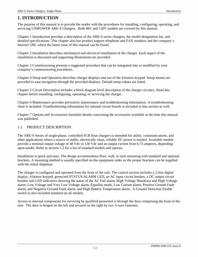
1. INTRODUCTION The purpose of this manual is to provide the reader with the procedures for installing, configuring, operating, and servicing UNIPOWER ARE-S Chargers. Both 48V and 130V models are covered by this manual. Chapter 1 Introduction provides a description of the ARE-S series chargers, the model designation list, and detailed specifications. This chapter also has product support telephone and FAX numbers and the company’s Internet URL where the latest issue of this manual can be found. Chapter 2 Installation describes mechanical and electrical installation of the charger. Each aspect of the installation is discussed and supporting illustrations are provided. Chapter 3 Commissioning presents a suggested procedure that can be integrated into or modified by your company’s commissioning procedures. Chapter 4 Setup and Operation describes charger displays and use of the 4-button keypad. Setup menus are provided to ease navigation through the provided displays. Default setup values are listed. Chapter 5 Circuit Description includes a block diagram level description of the charger circuitry. Read this chapter before installing, configuring, operating, or servicing the charger. Chapter 6 Maintenance provides preventive maintenance and troubleshooting information. A troubleshooting chart is included. Troubleshooting information for internal circuit boards is included in this section as well. Chapter 7 Options and Accessories furnishes details concerning the accessories available at the time this manual was published. 1.1 PRODUCT DESCRIPTION The ARE-S Series of single-phase, controlled SCR float chargers is intended for utility, communications, and other applications where a source of stable, electrically clean, reliable DC power is needed. Available models provide a nominal output voltage of 48 Vdc or 130 Vdc and an output current from 6-75 amperes, depending upon model. Refer to section 1.2 for a list of standard models and options. Installation is quick and easy. The design accommodates floor, wall, or rack mounting with standard and optional brackets. A mounting method is usually specified on the equipment order so the proper brackets can be supplied with the initial shipment. The charger is configured and operated from the front of the unit. The control section includes a 2-line digital display, 4-button keypad, green/red STATUS/ALARM LED, an AC input circuit breaker, a DC output circuit breaker and LED indicators showing the status of the AC Fail alarm, High Voltage Shutdown and High Voltage alarm, Low Voltage and Very Low Voltage alarm, Equalize mode, Low Current alarm, Positive Ground Fault alarm, and Negative Ground Fault alarm, and High Battery Temperature alarm. A Ground Detection Enable switch is also included standard on all models. Access to internal components for servicing by qualified personnel is through the door comprising the front of the unit. The door is hinged on the left and secured on the right by two ¼-turn fasteners.
ARE-S Series Chargers, Single Phase Introduction
PM990.1090.XX, Issue 8 1-2
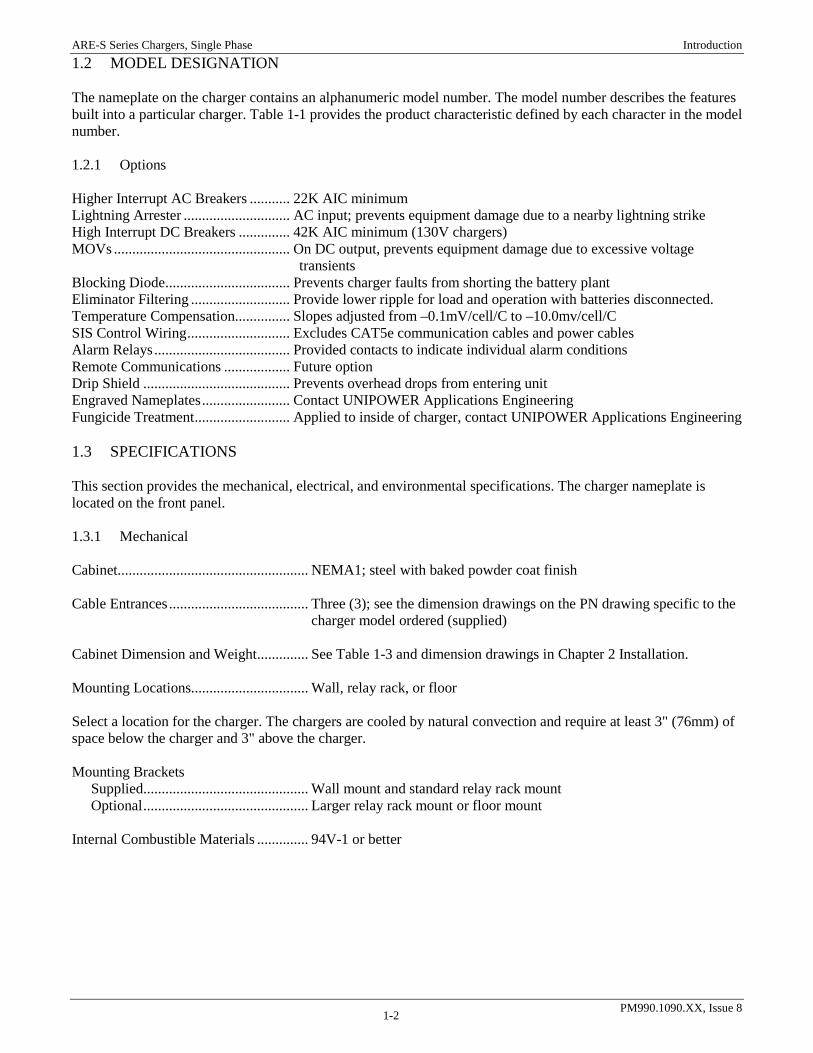
1.2 MODEL DESIGNATION The nameplate on the charger contains an alphanumeric model number. The model number describes the features built into a particular charger. Table 1-1 provides the product characteristic defined by each character in the model number. 1.2.1 Options Higher Interrupt AC Breakers ........... 22K AIC minimum Lightning Arrester ............................. AC input; prevents equipment damage due to a nearby lightning strike High Interrupt DC Breakers .............. 42K AIC minimum (130V chargers) MOVs ................................................ On DC output, prevents equipment damage due to excessive voltage
transients Blocking Diode .................................. Prevents charger faults from shorting the battery plant Eliminator Filtering ........................... Provide lower ripple for load and operation with batteries disconnected. Temperature Compensation ............... Slopes adjusted from –0.1mV/cell/C to –10.0mv/cell/C SIS Control Wiring ............................ Excludes CAT5e communication cables and power cables Alarm Relays ..................................... Provided contacts to indicate individual alarm conditions Remote Communications .................. Future option Drip Shield ........................................ Prevents overhead drops from entering unit Engraved Nameplates ........................ Contact UNIPOWER Applications Engineering Fungicide Treatment .......................... Applied to inside of charger, contact UNIPOWER Applications Engineering 1.3 SPECIFICATIONS This section provides the mechanical, electrical, and environmental specifications. The charger nameplate is located on the front panel. 1.3.1 Mechanical Cabinet .................................................... NEMA1; steel with baked powder coat finish Cable Entrances ...................................... Three (3); see the dimension drawings on the PN drawing specific to the
charger model ordered (supplied) Cabinet Dimension and Weight .............. See Table 1-3 and dimension drawings in Chapter 2 Installation. Mounting Locations................................ Wall, relay rack, or floor Select a location for the charger. The chargers are cooled by natural convection and require at least 3" (76mm) of space below the charger and 3" above the charger. Mounting Brackets Supplied ............................................. Wall mount and standard relay rack mount Optional ............................................. Larger relay rack mount or floor mount Internal Combustible Materials .............. 94V-1 or better

ARE-S Series Chargers, Single Phase Introduction
PM990.1090.XX, Issue 8 1-3
TABLE 1-1 48V Model Designation
DC VOLTAGE & CURRENTARE-S4806A (AC Input Voltage: 120V/208V/240V)ARE-S4812A (AC Input Voltage: 120V/208V/240V)ARE-S4830A (AC Input Voltage: 120V/208V/240V)ARE-S4850A (AC Input Voltage: 120V/208V/240V)
AC Input Voltage / BreakerA 120V - 60 Hz Standard Capacity (10kAIC) AC BreakerB 208V - 60 Hz Standard Capacity (10kAIC) AC BreakerC 240V - 60 Hz Standard Capacity (10kAIC) AC Breaker E 120V - 60 Hz Medium Capacity (22kAIC) AC BreakerF 208V - 60 Hz Medium Capacity (22kAIC) AC BreakerG 240V - 60 Hz Medium Capacity (22kAIC) AC BreakerJ 120V - 60 Hz High Capacity (42kAIC) AC BreakerK 208V - 60 Hz High Capacity (42kAIC) AC BreakerL 240V - 60 Hz High Capacity (42kAIC) AC Breaker
AC ProtectionN Not Required (Standard)2 120/240 VAC Input Lightning Arrestor
DC Circuit BreakerD High Capacity DC Breaker
DC ProtectionN None (Standard)1 MOVs
Blocking DiodeN None (Standard)1 Yes (Negative Leg)
DC FilteringF Filtered (Standard)E Eliminator
Temperature CompensationN Not Required (Standard)1 Battery Temperature Compensation (Temperature Sensor with 25' lead)
Control Wiring1 PVC (Standard)2 SIS - Switchboard Wire - all wiring except ribbon cables and power cables
Auxiliary Alarm BoardN AC Fail, High Voltage Shutdown, Rectifier Fail (Standard)1 Individual Alarm Relays
Communications PortN None
MountingW Wall Mounted (Standard)R For 19" Relay Rack (6A, 12A, 16A, 25A only)2 For 23" Relay Rack (all)F FloorD Floor with Drip Top
PackagingD Domestic (Standard)E ExportN None (for factory installation in a rack)
ARE-S 4812 A 2 S 1 1 E 1 1 1 N W DBase Model S Build Number

ARE-S Series Chargers, Single Phase Introduction
PM990.1090.XX, Issue 8 1-4
TABLE 1-2 130V Model Designation
DC VOLTAGE & CURRENT
ARE-S13006A (AC Input Voltage: 120V/208V/240V)
ARE-S13012A (AC Input Voltage: 120V/208V/240V/480V)
ARE-S13016A (AC Input Voltage: 120V/208V/240V/480V)
ARE-S13025A (AC Input Voltage: 120V/208V/240V/480V)
ARE-S13035A (AC Input Voltage: 120V/208V/240V/480V)
ARE-S13050A (AC Input Voltage: 208V/240V/480V)
ARE-S13075A (AC Input Voltage: 240V/480V)
| AC Input Voltage / Breaker
| A 120V - 60 Hz Standard Capacity (10kAIC) AC Breaker
| B 208V - 60 Hz Standard Capacity (10kAIC) AC Breaker
| C 240V - 60 Hz Standard Capacity (10kAIC) AC Breaker
| D 480V - 60 Hz Standard Capacity (18kAIC) AC Breaker
| E 120V - 60 Hz Medium Capacity (22kAIC) AC Breaker
| F 208V - 60 Hz Medium Capacity (22kAIC) AC Breaker
| G 240V - 60 Hz Medium Capacity (22kAIC) AC Breaker
| H 480V - 60 Hz Medium Capacity (25kAIC) AC Breaker
| J 120V - 60 Hz High Capacity (42kAIC) AC Breaker
| K 208V - 60 Hz High Capacity (42kAIC) AC Breaker
| L 240V - 60 Hz High Capacity (42kAIC) AC Breaker
| M 480V - 60 Hz High Capacity (65kAIC) AC Breaker
| | AC Protection
| | N Not Required (Standard)
| | 2 120/240 VAC Input Lightning Arrestor
| | 3 480 VAC Input Lightning Arrestor
| | | DC Circuit Breaker
| | | S Standard Capacity (For 120V, 208V, or 240V)
| | | D High Capacity DC Breaker (For 120V, 208V, or 240V)
| | | 1 High Capacity AC Breaker/Standard Capacity DC Breaker (For 480V only)
| | | 2 High Capacity AC Breaker/High Capacity DC Breaker (For 480V only)
| | | | DC Protection
| | | | N None (Standard)
| | | | 1 MOVs
| | | | | Blocking Diode
| | | | | N None (Standard)
| | | | | 1 Yes (120,208,240)
| | | | | 2 Yes (480)
| | | | | | DC Filtering
| | | | | | F Filtered (Standard)
| | | | | | E Eliminator
| | | | | | | Temperature Compensation
| | | | | | | N Not Required (Standard)
| | | | | | | 1 Battery Temperature Compensation (Temperature Sensor with 25' lead)
| | | | | | | | Control Wiring
| | | | | | | | 1 PVC (Standard)
| | | | | | | | 2 SIS - Switchboard Wire - all wiring except ribbon cables and power cables
| | | | | | | | | Auxiliary Alarm Board
| | | | | | | | | N AC Fail, High Voltage Shutdown, Rectifier Fail (Standard)
| | | | | | | | | 1 Individual Alarm Relays
| | | | | | | | | | Communications Port
| | | | | | | | | | N None
| | | | | | | | | | | Mounting
| | | | | | | | | | | W Wall Mounted (Standard)
| | | | | | | | | | | R For 19" Relay Rack (6A, 12A, 16A, 25A only)
| | | | | | | | | | | 2 For 23" Relay Rack (all)
| | | | | | | | | | | F Floor
| | | | | | | | | | | D Floor with Drip Top
| | | | | | | | | | | | Packaging
| | | | | | | | | | | | D Domestic (Standard)
| | | | | | | | | | | | E Export
| | | | | | | | | | | | N None (for factory installation in a rack)
| | | | | | | | | | | | || | | | | | | | | | | | || | | | | | | | | | | | || | | | | | | | | | | | |
ARE-S 13025 A 2 S 1 1 E 1 1 1 N W D
Base Model S Build Number

ARE-S Series Chargers, Single Phase Introduction
PM990.1090.XX, Issue 8 1-5
TABLE 1-3 Cabinet Dimensions by Model
Model Cabinet Size Height* Width* Depth
Maximum* Mounting Depth**
Shipping Weight*
ARE-S4806 ARE-S4812 ARE-S13006
12" 12.25 (311)
17 (432)
15 (381)
6 (152)
104 (47) 110 (50) 103(47)
ARE-S4830 ARE-S13012 ARE-S13016 ARE-S13025
17" 17.5 (445)
17 (432)
15 (381)
6 (152)
168 (76) 151 (69) 170 (77) 220 (100)
ARE-S4850 ARE-S13012 (480 V) ARE-S13016 (480 V) ARE-S13025 (480 V) ARE-S13035
24" 24.5 (622)
17 (432)
17 (381)
6 (152)
235 (107) 181 (82) 200 (91) 250(114) 306 (139)
ARE-S13050 ARE-S13075 30" 30
(762) 20.5 (521)
19 (483)
11.625 (295)
404 (183) 468 (212)
*Cabinet dimension in inches (mm). Does not include mounting brackets or drip shield. Approximate weight in lbs (kgf). ** Dimension from cabinet front to installed rack mounting angle brackets.
1.3.2 Electrical General AC Voltage Range ............................ The AC supply voltage specified in Model Specific and Related
Specifications must be within the following ranges:
TABLE 1-4 General AC Voltage Range Nominal Voltage Minimum Voltage Maximum Voltage
120 Vac 106 Vac 132 Vac 208 Vac 184 Vac 228 Vac 240 Vac 212 Vac 264 Vac 480 Vac 424 Vac 528 Vac
AC Frequency ............................................. 57-63 Hz Power Factor (Resistive Load) .......... >0.632 at full load (48V), >0.62 at full load (130V) Efficiency (Resistive Load) ............... >0.74% (48V), >0.78% (130V) AC Breaker Interrupt (Standard) ................. 10k AIC @120/208/240 V, 18k AIC @ 480 V AC Breaker Interrupt Medium Capacity (Optional) ... 22k AIC @120/208/240 V, 25k AIC @ 480 V AC Breaker Interrupt High Capacity (Optional) ......... 42k AIC @ 120/208/240 V, 65k AIC @ 480 V Rated DC Output Voltage ........................... 52.8V or 132 V No. Cells, Lead-Acid ................................... 24 or 60, respectively Nickel Cadimum .......................... 37–38 or 92–93, respectively DC Regulation Static Float ........................................ ±0.5% with a fixed load and simultaneous variations1 Equalize .................................. ±1.0% with a fixed load and simultaneous variations Dynamic ....................................... ±6% for a step load change of 10 to 90% or 90 to 10% of rated current;
Charger will recover to regulation range within 300 milliseconds.2
1 Load, input voltage, frequency, and temperature varied within range for that model.

ARE-S Series Chargers, Single Phase Introduction
PM990.1090.XX, Issue 8 1-6
Current Limiting Factory Setting .......................... 110% of full rated load Field Settable ............................. 50-110% of full rated load Continuous Operation ................ 110% of full rated load maximum Surge Protection ................................ Optional lightning arrestor on input terminals Optional MOVs (metal-oxide varistors) on output terminals Current Walk-In (Soft Start) ............. Less than 15 seconds for output current increase from 0-100% Ripple – 130V Filtered (Standard) ............. On Battery 100 mV rms*, maximum Off Battery 2% rms of output voltage, maximum 130V Eliminator (Optional) ......... On Battery 100 mV rms*, maximum Off Battery 100 mV rms, maximum 48V Filtered (Standard) ............... On Battery 30mV rms*, maximum Off Battery 1% rms of output voltage, maximum 48V Eliminator (Optional) ........... On Battery 30 mV rms*, maximum Off Battery 30 mV rms, maximum *Battery: A fully charged battery that has an ampere-hour (AH) capacity numerically equal to four (4) times the rated output current of the charger. 48V Chargers DC Breaker Interrupt High Capacity (Standard) ... ….. 50k AIC 130V Chargers DC Breaker Interrupt (Standard) ................. ............... 10k AIC DC Breaker Interrupt High Capacity (Optional) ......... 42k AIC Alarm Indicators Front Panel ................................ Red/green STATUS LED and 2-Line backlit LCD display
Additional front panel indicators, consisting of a red AC Fail LED, yellow/red High Voltage Shutdown/High Voltage LED, yellow/red Low Voltage/Very Low Voltage LED, yellow Equalize LED, red High Battery Temperature LED, yellow Low Current LED, and green Positive and Negative Ground Fault LEDs
Standard Relays ................................. 3 relay outputs: AC Fail, Rectifier Fail, and High Voltage Shutdown (HVSD)
Optional Relays ................................. 10 relay outputs: High Voltage Alarm (HVA), Low Voltage Alarm (LVA), Equalize (EQ), High Battery Temperature Alarm (HBTA), Low Current Alarm (LCA), Ground Positive (GND+), Ground Negative (GND-), Summary (SUM), 2 future expansions
Alarm Relay Contacts ....................... 1 Form C, Contact Rating 60W/62.5VA, 2 Amps max switching current & 220Vdc/250Vac max switching voltage
Connector .................................. One plug-in 3-position terminal block per alarm, compression-style wire clamp
Wire Size ................................... 16-28 AWG (1.5-0.08 mm2)
2 On battery – The ampere-hour (AH) capacity of the battery equal to at least four (4) times the rated output of the charger.

ARE-S Series Chargers, Single Phase Introduction
PM990.1090.XX, Issue 8 1-7
TABLE 1-5 Model Specific and Related Specifications
Refer to the equipment nameplate for the model number of the ARE-S at hand.
Model Input Current, 120/208/240
Output Current
Recommended DC Cable Size,
AWG
DC Terminal Capacity
DC Circuit Breaker
ARE-S4806 6/3.5/3 6 14 12 – 22 10 ARE-S4812 12/7/6 12 10 12 – 22 20 ARE-S4830 27/16/14 30 8 2/0 - 14 40 ARE-S4850 40/23/20 50 6 2/0 - 14 70
Model Input Current, 120/208/240/480
Output Current
Recommended DC Cable Size,
AWG
DC Terminal Capacity
DC Circuit Breaker
ARE-S13006 14/8/7/-- 6 14 12 – 22 10* ARE-S13012 25/15/13/6.5 12 10 2/0 - 14 20 ARE-S13016 35/20/18/9 16 10 2/0 - 14 20 ARE-S13025 48/28/24/12 25 8 2/0 - 14 40 ARE-S13035 75/43/38/19 35 8 2/0 - 14 50 ARE-S13050 --/66/57/29 50 4 2/0 - 14 70 ARE-S13075 --/--/80/40 75 4 2/0 - 14 100
*15 A for High Interrupt device.
1.3.3 Front Panel Displays and Controls Display .............................................. LCD, 2 lines x 20 characters, with LED backlight Display Accuracy .............................. 1% minimum (voltage, current, frequency, temperature, or time) Control Modes ................................... Manual float/equalize, user selectable from keypad LED Indication .................................. STATUS – Alarm/red, OK/green; ACF/red, HVSD/red, HVA/yellow,
VLVA/red, LVA/yellow, EQ/yellow, High-Low Batt Temp/red, LCA/yellow, +GND/green, –GND/green
High Voltage Shutdown Adjustable .................................... 2.00-2.53 Vpc (Volts per cell), LED indicator; see table 1-4; 15-20
second delay programmable Fixed Redundant .......................... 2.66 +/-0.08 Vpc, 20 second delay fixed Float/Equalize ................................... State indicated; Equalize remaining time shown Load Share Active ............................. Chargers operating in parallel within +/-5% of rated output of the largest
charger over 10% to 100% of the total charger capacities Ground Detection Disconnect Switch ............................. Breaks the connection to the chassis (earth) for troubleshooting grounds
on the dc system or to eliminate interaction with an external ground detection system
Relay/Lamp Test ............................... Provided in setup routine (password protection available) Control Adjustments (password protection available) Float Voltage ................................ 2.00-2.35 Vpc (Volts per cell); see table 1-4 Equalize Voltage .......................... 2.00-2.45 Vpc; see table 1-4 Manual Equalize .......................... Off (default), Equalize Duration (1-255 hours) Auto-Equalize After AC Fail .......................... Off (default), Equalize After (1-7200 minutes), Equalize Duration (1-255
hours) Periodic ................................... Off (default), Equalize Duration (1-255 hours), 168-8760 hrs period Current Limit ............................... 50-110% of charger rating Temp Comp……………………...0.1-10mV/cell/°C
ARE-S Series Chargers, Single Phase Introduction
PM990.1090.XX, Issue 8 1-8
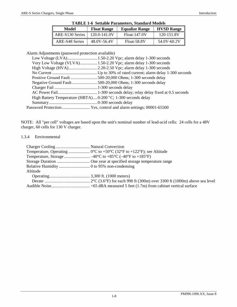
TABLE 1-6 Settable Parameters, Standard Models
Model Float Range Equalize Range HVSD Range ARE-S130 Series 120.0-141.0V Float-147.0V 120-151.8V ARE-S48 Series 48.0V-56.4V Float-58.8V 54.0V-60.2V
Alarm Adjustments (password protection available) Low Voltage (LVA) ............................ 1.50-2.20 Vpc; alarm delay 1-300 seconds Very Low Voltage (VLVA) ................ 1.50-2.20 Vpc; alarm delay 1-300 seconds High Voltage (HVA) ........................... 2.20-2.50 Vpc; alarm delay 1-300 seconds No Current .......................................... Up to 30% of rated current; alarm delay 1-300 seconds Positive Ground Fault ......................... 500-20,000 Ohms; 1-300 seconds delay Negative Ground Fault ........................ 500-20,000 Ohms; 1-300 seconds delay Charger Fail ........................................ 1-300 seconds delay AC Power Fail ..................................... 1-300 seconds delay; relay delay fixed at 0.5 seconds High Battery Temperature (HBTA) .... 0-200 °C; 1-300 seconds delay Summary ............................................. 0-300 seconds delay Password Protection .......................... Yes, control and alarm settings; 00001-65500 NOTE: All "per cell" voltages are based upon the unit's nominal number of lead-acid cells: 24 cells for a 48V charger, 60 cells for 130 V charger. 1.3.4 Environmental Charger Cooling ................................ Natural Convection Temperature, Operating .................... 0°C to +50°C (32°F to +122°F); see Altitude Temperature, Storage ........................ –40°C to +85°C (–40°F to +185°F) Storage Duration ............................... One year at specified storage temperature range Relative Humidity ............................. 0 to 95% non-condensing Altitude Operating ...................................... 3,300 ft. (1000 meters) Derate .......................................... 2°C (3.6°F) for each 990 ft (300m) over 3300 ft (1000m) above sea level Audible Noise .................................... <65 dBA measured 5 feet (1.7m) from cabinet vertical surface

ARE-S Series Chargers, Single Phase Introduction
PM990.1090.XX, Issue 8 1-9
1.4 ABBREVIATIONS AND ACRONYMS Listed here are many of the abbreviations and acronyms that may appear in this manual.
Abbreviation, Acronym Or Symbol Meaning
+ -
AC ACF ANSI
plus or positive minus or negative alternating current AC Fail American National Standards Institute
AWG american wire gauge BATT battery
CL current limit CM circular mils DC DN EMI
direct current down key electromagnetic interference
EQ Equ.
equalize equalize
ESD ESC
electrostatic discharge escape key
FW FL
GND HBTA
firmware float ground high battery temperature alarm
HVA high voltage alarm HVSD high voltage shutdown
LCA (NCA) low current alarm (no current/charge alarm) LED light emitting diode LSD least significant digit LVA low voltage alarm LVD low voltage disconnect NEC National Electric Code
NEMA OC
National Electrical Manufacturers Association over-current
PCB printed circuit board RECTF
RFA REM Rem. SEL TEL
rectifier fail rectifier failure alarm remote remote select key telecom
UL UTL
VLVA
Underwriters Laboratory utility very low voltage alarm
Vpc volts per cell

ARE-S Series Chargers, Single Phase Introduction
PM990.1090.XX, Issue 8 1-10
1.5 PRODUCT SUPPORT Product support can be obtained using the following addresses and telephone numbers. UNIPOWER, LLC 3900 Coral Ridge Drive Coral Springs, FL 33065 Phone: +1-954-346-2442 Toll Free: 1-800-440-3504 Web site – http://www.unipowerco.com When contacting UNIPOWER, please be prepared to provide:
1. The charger model number, spec number, S build number, and serial number - see the equipment nameplate on the front panel
2. Your company’s name and address
3. Your name and title
4. The reason for the contact
5. If there is a problem with charger operation:
• Is the problem intermittent or continuous?
• What revision is the firmware?
• What actions were being performed prior to the appearance of the problem?
• What actions have been taken since the problem occurred?
ARE-S Series Chargers, Single Phase Installation
PM990.1090.XX, Issue 8 2-1
2. INSTALLATION This chapter describes installing ARE-S Series Chargers. To contact a UNIPOWER field service technician for assistance, refer to Section 1.5 Product Support. The charger is fully assembled and tested at the factory. Refer to the Front Matter and Section 2.3 Unpacking for receiving and unpacking instructions and for instructions on moving the equipment to the installation site. These chargers can be mounted to a wall, in a relay rack, or on a floor. Mounting brackets are furnished with for the mounting method specified on the order. Cabinet dimensions and weights are provided in the Specifications section. Conduit openings with plugs are located in the cabinet top for AC input cables, DC output cables and alarm wiring. Cables and wires are supplied by the user. WARNING Electrical shock hazard Hazardous voltage can cause death or serious injury. Remove power from all wires and terminals before working on equipment.
AVERTISSEMENT Risque de choc électrique Les tensions dangereuses peuvent causer la mort ou des blessures graves. Coupez l'alimentation de tous les fils et les bornes avant de travailler sur les équipements.
IMPORTANT: The installation must conform to the National Electrical Code and other applicable industry and local codes. 2.1 INSTALLATION SUMMARY A typical installation sequence is provided below. References to appropriate sections in this manual are included.
1. Review the list of user-supplied tools and accessories in Section 2.2 Reference Material. This section also contains a table and a procedure for determining battery and distribution cable sizes based on current load and length of run. Refer to the National Electrical Code and other applicable codes to determine AC cable size.
2. Select a location for the charger. The chargers are convectional cooled and require at least 3" (76mm) of space below the charger and 3" above the charger. The charger must be mounted over a non-combustible surface. See Section 2.3 Mechanical Installation.
3. Move the charger to the selected location. See Section 2.3.
4. As appropriate, install charger mounting brackets for a wall, relay rack, or floor. Fasten the charger to the selected mounting surface or rack.
5. Install a user-supplied electrical service panel (as needed) for powering the charger. See Section 2.4 Electrical Installation. Install AC input conduit and wiring between the user’s AC electrical service panel and the charger.
6. Install battery cabling. Route cabling through overhead cable racks between the battery string and the charger DC output terminals.
7. Install customer load supply and return cabling. Connect the cabling to the battery string or directly to the charger, if a battery string is not to be connected to the charger. If the customer load is connected to the battery string, install a circuit breaker or fuse in-line with the cabling.
8. Connect user-supplied external alarm annunciators.
9. Commission the charger. See Chapter 3.

ARE-S Series Chargers, Single Phase Installation
PM990.1090.XX, Issue 8 2-2
10. Set LVA, HVA, HVSD, float voltage, equalization, etc. as needed to satisfy installation requirements. Test and verify charger setup and operation. See Chapter 4 Setup and Operation.
2.2 REFERENCE MATERIAL This section contains lists, tables, and methods that are referenced in subsequent procedures. Three subsections comprise the Reference Material section.
• Tools and Accessories – Read the included list for a preview of the user-supplied items that will be referenced during the installation and servicing procedures.
• Selecting and Sizing DC Power Cables – Proper cable sizing is critical to system performance. This section provides a formula and table that simplify cable selection.
• Torque Specifications – The torque specification table in this subsection is referenced in procedures that include hardware.
2.2.1 Tools and Accessories To install the charger, the following user-supplied items should be available.
• Equipment and personnel to safely transport the charger to the installation site
• Mounting brackets and related hardware to securely mount the charger
• Overhead wire racks for AC power and distribution cabling
• Standard insulated installation tools (e.g. socket set, cable cutters, cable insulation strippers)
• Torque wrench to ensure correct tightening of hardware; see Table 2-2 for torque specifications
• User-supplied AC electrical service panel with a circuit breaker for the AC feed to the charger
• Digital Voltmeter with: 4-1/2 digit display, 1/2% accuracy, and 10M ohms input impedance
• Cables and lugs; appropriate crimping tools
• Conduit, conduit connectors, and conduit bending tools
• Anti-Static Service Kit with static dissipative mat and wrist strap for handling electronic circuit boards (e.g. Control and Display Board, User Interface Board)
• 2.2.2 Selecting and Sizing DC Power Cables Protective circuits, overall system performance, and safety depend on the proper sizing of DC cables for ampere ranges and acceptable DC voltage drop. Read the electrical installation section before sizing the DC cables. Perform the following procedure to determine wire size.
1. Calculate the minimum circular mils (CM) required for copper wire using the following formula:
VLICM ∗∗
=2.22
Where:
CM = minimum area of circular mils in the cable I = maximum current (in amps) L = one-way cable length (in feet) V = allowable loop voltage drop (in volts)
Example:

ARE-S Series Chargers, Single Phase Installation
PM990.1090.XX, Issue 8 2-3
Assume a maximum output current of 25 amperes, an allowable loop voltage drop of 0.5 volts, and a distance of 50 feet between the charger and the load.
I = 25 amperes L = 50 feet V = 0.5 volts
000,55)5.0(
)50)(25)(2.22(==CM
11. After calculating the minimum circular mils, select the proper copper wire size from Table 2-1; always choosing the next larger wire size if the area rating falls between values. For the above example, select 2 AWG (35 mm2) wire.
12. Determine the minimum wire size for ampacity according to the code authority having jurisdiction in your location.
13. Select the larger of the sizes calculated for voltage drop or ampacity.
TABLE 2-1 Copper Wire Sizing
SIZE
AWG NO.
AREA IN CM
CURRENT CARRYING
CAPACITY* 75°C (167°F)
DIA BARE COND INCHES
RHW DIA OVER INS INCHES
RHW BEND RADIUS INCHES
RHW NET WEIGHT PER 1000 FT IN POUNDS
RHW MAX SHIP LENGTHS PER REEL IN FEET
OPEN AIR
ENCLOSED
14 4,110 15 15 0.064 0.19 0.95 26 5,000 12 6,530 20 18 0.081 0.21 1.05 35 3,000 10 10,380 30 25 0.102 0.24 1.20 49 3,000 8 16,510 45 35 0.146 0.31 1.55 84 3,000 6 26,250 70 45 0.184 0.40 2.00 126 2,000 4 41,740 90 60 0.232 0.45 2.25 190 1,500 2 66,370 125 85 0.292 0.51 2.55 278 1,000
1/0 105,500 170 110 0.373 0.63 3.15 443 1,000 2/0 133,100 195 130 0.418 0.68 3.40 540 1,000 4/0 211,600 270 170 0.528 0.78 3.90 814 1,000
Data based on NEC Handbook 2005, Table 310-16 and 310-17 adjusted for 50°C (122°F) ambient temperature.

ARE-S Series Chargers, Single Phase Installation
PM990.1090.XX, Issue 8 2-4
2.2.2.1.1 Torque Specifications Proper Charger performance requires that the hardware employed during installation be tightened securely, but not over tightened. Use a torque wrench to ensure that hardware is tightened to the specification provided in the table 2-2.
TABLE 2-2 Torque Specifications, Steel Fasteners
Bolt Size Inch-Pounds Foot-Pounds Newton-Meters 4-40 4.5 0.375 0.51 4-48 5.4 0.450 0.61 6-32 9.0 0.750 1.02 6-40 10.8 0.900 1.22 8-32 17.1 1.425 1.93 8-36 18.0 1.500 2.03
10-24 24.3 2.025 2.75 10-32 27.9 2.325 3.15
1/4-20 59.4 4.950 6.71 1/4-28 70.2 5.850 7.93
5/16-18 118.8 9.9 13.42 5/16-24 129.6 10.8 14.64
3/8-16 216.0 18.0 24.40 3/8-24 248.4 20.7 28.07
7/16-14 324.0 27.0 36.61 7/16-20 378.0 31.5 42.71
1/2-13 540.0 45.0 61.01 1/2-20 594.0 49.5 67.11
9/16-12 756.0 63.0 85.42 9/16-18 864.0 72.0 98.62
2.3 MECHANICAL INSTALLATION Install the charger in a location that provides:
• A dry, well ventilated, vibration-free environment with temperature and humidity limits as stated in Section 1.3 Specifications
• Sufficient access for installation and servicing
• Sufficient ceiling height to permit use of overhead cable trays for distribution wiring
• A level, flat floor or a wall capable of supporting the weight of the charger and accepting anchoring bolts
• A non-combustible surface beneath the charger
• A pest and varmint free area Charger dimensions are stated in the Section 1.3 Specifications and shown in the accompanying PN drawing for each charger. Charger weight is provided in the Specifications section. The mounting method (floor, rack, or wall) is usually specified on the order so the necessary brackets are installed on the charger at the factory. Charger wall mounting hardware (1/4-20 screws, lock washers and nuts), rack mounting hardware (12-24 screw and nuts) or floor mount hardware (3/8 bolts and anchors) is customer supplied since it must be selected on-site to be appropriate for the mounting surface.

ARE-S Series Chargers, Single Phase Installation
PM990.1090.XX, Issue 8 2-5
See the accompanying PN drawing for charger mounting bracket locations. Charger mounting options are listed below.
• 12", 17”, or 24" cabinets can be mounted in a 19" rack using factory supplied 19” rack brackets or in a 23”rack using factory supplied 23” rack brackets
• A 30" cabinet can be mounted in a 23" rack using the factory supplied rack brackets
• All cabinets can be fastened to a wall using factory supplied rack angle brackets fastened to rear of cabinet
• All cabinets can be free standing on a solid or elevated floor; optional floor mounting brackets are required
CAUTION Charger models that output 50 A or 75 A can have hot cabinet surfaces. Install these models so that top and rear cabinet surfaces are unlikely to be touched by personnel. Charger models with drip shields are to be placed where the shield is unlikely be in contact with people. The shield should not have anything set upon it.
ATTENTION La surface des cabinets peut être CHAUDE pour les modèles de chargeur avec une sortie de 50A ou 75A. Installez ces modèles dans un endroit ou ils sont peu susceptibles d'être touchés par le personnel. Les modèles avec un « pare-gouttes » doivent être placées là le dessus est peu probable d'être en contact avec du personnel. Ne rien placer sur le pare-gouttes.
2.4 ELECTRICAL INSTALLATION Each charger is internally connected for the nominal AC input voltage stated in the charger’s model number. Refer to the model number on the charger nameplate and the proper Table 1-1 or Table 1-2 Model Designation to be sure that the charger is intended for your incoming AC line voltage. If there are sustained AC voltage fluctuations outside the ranges given in the Specifications section of this manual, contact the Field Service Department of UNIPOWER. A block diagram of a typical charger electrical installation is shown in Figure 2-4. Note that the load is connected to the battery string terminals through a fuse or circuit breaker.
User's AC ElectricalService Panel
ARE SeriesFloat Charger
+_
Battery String+_
Load+_Single-Phase
AC InputDC Output
FIGURE 2-1 ELECTRICAL INSTALLATION, BLOCK DIAGRAM

ARE-S Series Chargers, Single Phase Installation
PM990.1090.XX, Issue 8 2-6
Chargers are furnished with three holes for top conduit entrances; see Figure 2-2. These holes can be enlarged to accommodate 1-1/2” conduit.
FIGURE 2-2 TYPICAL CHARGER ELECTRICAL ENTRANCE AND BREAKER LOCATIONS All charger connection terminals are accessed by opening the hinged front door panel. AC input and DC output power terminals are located on the accessory panel at the right front of the unit. The alarm terminal block is located on the Interface Board or optionally at the Extended Relay Board at the left front of the unit. AC and DC terminals are shown in Figures 2-6 and 2-6. Connection locations vary with cabinet size.

ARE-S Series Chargers, Single Phase Installation
PM990.1090.XX, Issue 8 2-7
Terminal Block, TB1
AC Input, L1
AC Input, L2or Neutral
AC Circuit Breaker
DC(+) Output
DC(-) Output
DC Circuit Breaker
AC Input, Ground
FIGURE 2-3 ELECTRICAL INSTALLATION TERMINALS, 12" CABINET MODELS *GENERIC; MAY VARY PER SYSTEM
AC Input L2or neutral
AC Input, L1
AC Input, Ground
DC (+) Output
DC (-) Output
AC Circuit Breaker DC Circuit Breaker
FIGURE 2-4 ELECTRICAL INSTALLATION TERMINALS, 17”, 24”, AND 30" CABINET MODELS

ARE-S Series Chargers, Single Phase Installation
PM990.1090.XX, Issue 8 2-8
2.4.1 Grounding the Cabinet Ground the charger to the site’s earth/safety ground. Figures 2-3 and 2-4 show the provided ground terminal. Connections must comply with the National Electrical Code and all applicable local codes and ordinances.
1. Open the front panel by loosening the quarter-turn captive screws at the right edge of the panel. Swing the panel open.
2. Locate the ground terminal near the upper center of the internal panel. It is labeled with a ground symbol. Internally, this terminal is connected to the charger cabinet/chassis.
3. Route the user-supplied ground wire through one of the cable entrance holes and connect it to the ground terminal.
4. Connect the other end of the cable to the site’s earth/safety ground.
2.4.2 Installing a User’s AC Electrical Service Panel The user should furnish an electrical service panel with either a fuse-protected AC disconnect switch or an AC circuit breaker for supplying power to the charger. Before selecting the rating of the protective device and the AC and DC cables sizes, check the equipment nameplate and the Specifications section in Chapter 1 for charger input and output voltage and current. The rating of the protective device on the power circuit feeding the unit must equal or exceed equipment breaker rating. The available fault current shall not exceed the interrupt rating list in section 1.3.2 for the model being installed. For locations with fault currents in excess of the standard capacity, optional high interrupting circuit breakers are required. Refer to the National Electrical Code (NEC) to select cable sizes. *Note: 24 inch and 30 inch cabinets require wire rated 75°C or greater. 2.4.3 Connecting AC Input Cables
1. Confirm the required AC input voltage. Refer to the model number on the charger nameplate and to the Model Designation table in Chapter 1. See the Specifications section in Chapter 1 for AC voltage and current requirements.
A tag in the unit tells the factory voltage setting. If the AC input voltage must be changed, contact UNIPOWER Field service for voltage changeover instructions. Refer to the PN and SD drawings to locate the cabinet assembly and schematic for the model at hand. Each schematic has a table and a connector detail drawing showing the needed connections. It is most likely that the AC breaker must also be changed if the voltage of the charger must be changed; DO NOT modify the voltage changeover without first verifying and installing the proper AC breaker.
2. Determine the AC input cable wire size. Refer to the National Electrical Code and local codes as necessary. The 24 inch and 30 inch cabinets require wire rated 75°C or greater.
3. At the charger, switch the AC input breaker to off.
4. Locate the conduit entrance hole and install conduit as necessary.
5. Route the AC cable from the user’s AC electrical service panel and into the charger cabinet. Strip the cable ends and install cable lugs, as desired.
6. Connect the cable to the AC input terminal block. See Figure 2-3 or 2-4 for connections. The power supply electrical circuits are isolated from ground so the AC supply must be connected to terminals TB1-1 and TB1-2 on all models.
7. At the user’s AC electrical service panel, set the circuit breaker to off. Connect the AC cable at the service panel.

ARE-S Series Chargers, Single Phase Installation
PM990.1090.XX, Issue 8 2-9
2.4.4 Connecting the Battery String Routing stiff, heavy gauge battery cables can be difficult. Two people may be needed. Exercise extreme caution to avoid a short circuit across the battery terminals. WARNING Arcing hazard Arcing can cause equipment damage, load interruptions, and personal injury. Remove watch and jewelry. Use insulated tools, appropriate arc flash personal protective equipment, and extreme caution when working with a battery string. Carefully insulate unterminated battery cable ends. Carefully check connection polarity.
AVERTISSEMENT Risque d'arc Un arc électrique peut causer des dommages sur les équipements, des interruptions de charge, et des blessures. Retirez vos montres et bijoux. Utiliser des outils isolés, équipement de protection individuelle approprié contre les arc éléctrique, et une prudence extrême lorsque vous travaillez avec des batteries. Isoler les extrémités des câbles de batterie. Vérifiez la polarité de connexion.
To connect the battery string:
1. Refer to the Specifications section in Chapter 1 for charger output current and recommended cable size. Additional cable selection information is provided in Section 2.2 Reference Material. The 24 inch and 30 inch units require wires rated 75°C or greater.
2. At the charger, locate the DC Output conduit entrance and install conduit as necessary.
3. Route the DC cable from the battery (or output load) to the charger and into the cabinet.
4. Switch the DC output circuit breaker to Off.
5. Connect the battery leads to the terminal block. See Figure 2-3 or 2-4 for the terminal block location. Mark the free cable ends with the polarity (+ or -).
6. At the battery, strip the wire ends and install lugs appropriate to the battery terminals.
7. Check cable polarity and connect the lugs to the battery (or output load) terminal plates or posts.
2.4.5 Connecting an External DC Load Load connections depend upon whether the charger is connected to a battery string.
• Battery String Connected – Connect the external load to the battery string terminals through a circuit breaker or fuse.
• Battery String Not Connected – Connect the external load to charger DC output terminals. Read the Warning statements in Section 2.4.4 Connecting the Battery String before proceeding. To connect a load:
1. Refer to the Specifications section in Chapter 1 for charger output current and recommended wire size. Refer to the charger nameplate and to the Model Designation table in Chapter 1 for the charger model number. Additional cable selection information is provided in Section 2.2 Reference Material. The 24 inch and 30 inch units require wire rated 75°C or greater.
2. At the charger, locate the DC Output conduit entrance and install conduit as necessary.
3. Route the DC supply and return cables between the load and either the battery or the charger.
4. At the load, connect the supply and return cables. Mark the free cable ends with the polarity (+/-).
5. At the battery string or charger, strip the wire ends and install lugs, as required.
ARE-S Series Chargers, Single Phase Installation
PM990.1090.XX, Issue 8 2-10
6. Carefully check cable polarity and connect the cables.
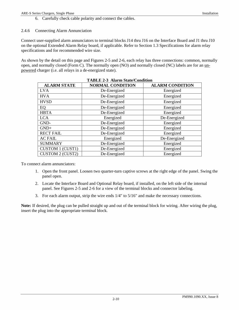
2.4.6 Connecting Alarm Annunciation Connect user-supplied alarm annunciators to terminal blocks J14 thru J16 on the Interface Board and J1 thru J10 on the optional Extended Alarm Relay board, if applicable. Refer to Section 1.3 Specifications for alarm relay specifications and for recommended wire size. As shown by the detail on this page and Figures 2-5 and 2-6, each relay has three connections: common, normally open, and normally closed (Form C). The normally open (NO) and normally closed (NC) labels are for an un-powered charger (i.e. all relays in a de-energized state).
TABLE 2-3 Alarm State/Condition ALARM STATE NORMAL CONDITION ALARM CONDITION
LVA De-Energized Energized HVA De-Energized Energized HVSD De-Energized Energized EQ De-Energized Energized HBTA De-Energized Energized LCA Energized De-Energized GND- De-Energized Energized GND+ De-Energized Energized RECT FAIL De-Energized Energized AC FAIL Energized De-Energized SUMMARY De-Energized Energized CUSTOM 1 (CUST1) De-Energized Energized CUSTOM 2 (CUST2) De-Energized Energized
To connect alarm annunciators:
1. Open the front panel. Loosen two quarter-turn captive screws at the right edge of the panel. Swing the panel open.
2. Locate the Interface Board and Optional Relay board, if installed, on the left side of the internal panel. See Figures 2-5 and 2-6 for a view of the terminal blocks and connector labeling.
3. For each alarm output, strip the wire ends 1/4" to 5/16" and make the necessary connections. Note: If desired, the plug can be pulled straight up and out of the terminal block for wiring. After wiring the plug, insert the plug into the appropriate terminal block.
ARE-S Series Chargers, Single Phase Installation
PM990.1090.XX, Issue 8 2-11
CD
0004
1a
Removable Plug
TB1, Interface Board-Mounted Terminal Blocks
Customer Alarm Wiring
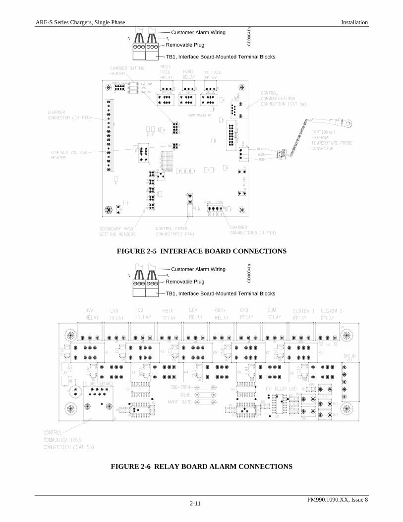
FIGURE 2-5 INTERFACE BOARD CONNECTIONS
CD
0004
1a
Removable Plug
TB1, Interface Board-Mounted Terminal Blocks
Customer Alarm Wiring
FIGURE 2-6 RELAY BOARD ALARM CONNECTIONS

ARE-S Series Chargers, Single Phase Installation
PM990.1090.XX, Issue 8 2-12
2.4.7 Connecting the Battery Temperature Probe (Option) When the battery temperature probe option is ordered with the charger, a temperature probe is connected to the charger’s Interface Board and the probe and wires coiled and tied near the Interface Board, behind the front panel. To connect the battery temperature probe:
1. Open the front panel. Loosen two quarter-turn captive screws at the right edge of the panel. Swing the panel open.
2. If not already connected, connect the probe’s three wires into P2, then plug P2 into J2 on the Interface Board as shown in Figure 2-5.
3. Route the probe to the battery string. Cable length is approximately 25 feet (8m).
4. Determine which battery cell or group of cells will have the highest operating temperature.
5. Determine the charge/discharge status of the battery string. Connecting the probe may result in a momentary battery string open circuit when the terminal bolt is removed.
CAUTION DO NOT proceed if the battery string is in a high charge or discharge state.
ATTENTION NE PAS procéder si la batterie est en haute recharge ou en mode décharge.
6. Remove the bolt holding the intercel battery strap in place. Insert the bolt through the battery temperature probe ring lug, through the strap, and into the battery terminal. Tighten the bolt as recommended by the battery manufacturer.
7. Bundle and secure any excess wire. During commissioning, enable battery temperature compensation using the front panel keypad and 2-line display. (See section 4.3)

ARE-S Series Chargers, Single Phase Commissioning
PM990.1090.XX, Issue 8 3-1
3. COMMISSIONING This chapter describes configuring, commissioning, and operating an ARE-S Series unit. A front view of a typical charger is shown in Figure 3-1. All operator controls are on the front of the charger.
DC On/OffCircuit Breaker
AC On/OffCircuit Breaker
2-LineDisplay
4-ButtonKeypad
FIGURE 3-1 OPERATOR CONTROLS (FRONT VIEW TYP.) The front of the unit has a large, high-contrast 2-line digital display, a 4-button keypad with tactile feedback for positive data entry, LEDs for charger status and alarm indications, and AC and DC circuit breakers. A microcontroller manages charger operation. The keypad and display provide the means for entering charger setup data (e.g. float voltage, high voltage shutdown, and temperature compensation on/off, etc). IMPORTANT: Press the keypad with your finger. Pressing with a sharp or pointed tool will damage the switch overlay and can damage the switch itself. The following two sections will describe charger commissioning. 3.1 PREPARATORY STEPS Perform the following steps prior to actually commissioning a charger.
1. Gather system wiring diagrams, battery data sheets, and other site documentation for ready reference should it be needed.
2. Check that all installation steps have been completed. Review Chapter 2 Installation. The system can be commissioned with or without a battery string.
3. If a battery string is connected to the charger, temporarily disconnect any external load connected to the battery string.
4. Review the steps in Section 3.2 Commissioning Procedure.
5. Become familiar with the operation of the front panel and the setup menus by reading Chapter 4 Setup and Operation.
6. Read the two statements below to determine whether charger setup parameter values can be displayed and edited prior to application of AC power to the charger. See Chapter 4 Setup and Operation for setup details. Table 4-1 lists default parameters and values.

ARE-S Series Chargers, Single Phase Commissioning
PM990.1090.XX, Issue 8 3-2
132.0VDC 0.0ADC FLOAT
ACTIVE ALARMS LCA
• Battery String Connected to Charger – The string will power the charger controller if there is at least a minimal battery charge. The 2-line display, keypad, and Alarm LEDs will be active. The setup can be edited at the charger front panel without applying AC power to the charger. Note that the 2-line LCD display and control power will become active as soon as the battery string is connected; the DC breaker does not have to be closed to power the controller.
• No Battery String Connected – When AC power is applied to the charger, the controller will load a default charger setup. You may then use the front panel to change many of the default parameter values to accommodate the application.
7. Set the AC and DC breakers on the charger front panel to Off.
8. Finally, perform the steps in Section 3.2 Commissioning Procedure.
3.2 COMMISSIONING PROCEDURE This procedure assumes a newly installed system that includes a connected battery string and load. The voltages and currents shown in the screens in this section are examples. They can vary with the charger model, charger setup, connected load, and other factors.
1. Check that the AC and DC circuit breakers on the charger front panel are switched to off.
2. Check that the circuit breaker in the user’s AC electrical service panel is switched off.
3. Check that:
• The AC input cable is connected to the correct terminals and that connections are tight
• DC load and battery cables are correctly connected and that connections are tight; check polarity as well.
• Alarm wiring is correct and tight, and that user-supplied alarm annunciators function
• The charger chassis is correctly grounded
4. At the user’s AC electrical service panel, switch the AC circuit breaker on to power the charger.
5. At the charger, switch the AC input breaker on. The DC output current will build up gradually due to the “walk-in” or “soft-start” characteristic of the equipment. The AC Fail alarm should clear when AC voltage input to the charger is detected. The 2-line display will show the Home screen. If an alarm is present, the display will indicate an alarm on the Home screen; pressing the down button will indicate the alarms. The STATUS LED will be lit RED if an alarm condition exits; this is the case as a Low Charge Alarm most likely still exists. See step 4 for sample displays.
6. Switch the DC output breaker on the charger front panel to on.
• Battery string connected to charger – The filter capacitors connected across the DC output will be charged by the string. The 2-line display on the front panel should show the battery voltage and current. Note: The inrush current may trip the DC breaker. If so, quickly re-close the breaker. The STATUS LED should be GREEN at the start-up. The STATUS Alarm LED may turn RED since all loads are disconnected, a low current alarm condition and the AC power is off (AC Fail condition). The low voltage alarm may be activated if the batteries are not fully charged. The factory-installed or user-edited setup will specify the low current alarm value (default 2% of charger rating).
• No battery string connected – The 2-line display will not be active. The capacitors will charge when the AC input breaker is closed in step 6. Both the output current and voltage will build up gradually, provided some load is connected.

ARE-S Series Chargers, Single Phase Commissioning
PM990.1090.XX, Issue 8 3-3
7. Connect a load of about 10% of charger capacity to the battery terminals through a circuit breaker or fuse. If a battery string is not connected, wire the load directly to the charger DC output terminals. Refer to the Section 2 Installation as necessary.
8. Refer to Chapter 4 Setup and Operation and use the front panel keypad and menus to:
1) Turn off battery temperature compensation. (Note: If the float voltage is set at high or low battery temperature with battery temperature compensation turned on, compensation may adjust the charger voltage by as much as 2 volts.)
2) If not performed previously, configure the charger by editing the factory setup to set the Float voltage, Equalize voltage, and other parameters to accommodate the application. Always refer to the battery manufacturers recommendations for setting up Float and Equalize parameters.
9. Thoroughly test the setup to ensure that all configurable parameters are correct for the application. Test the alarm circuits to ensure correct activation and annunciation.
10. Operate the system for 15-20 hours to charge the battery string(s) before placing the system on-line or as recommended by the battery manufacturer.
ARE-S Series Chargers, Single Phase Setup and Operation
PM990.1090.XX, Issue 8 4-1
4. SETUP AND OPERATION This chapter describes setting up and operating an ARE-S Series Charger using the 2-line display and 4-button keypad on the charger. See Figure 3-1 for the location of the panel, display, and keypad. The figure also shows the locations of the AC and DC circuit breakers mentioned in sections 4.1 & 4.2. 4.1 TURNING ON A COMMISSIONED CHARGER 1. Set the AC and DC circuit breakers on the front of the charger to off. See Figure 3-1 for the location of the
breakers.
2. At the user’s AC electrical service panel, switch on the appropriate circuit breaker to supply power to the charger.
3. At the charger, switch the AC circuit breaker on. The message “Start” will appear and output current will build up gradually due to the “walk-in” or “soft-start” characteristic of the equipment. During of normal startup, the alarm LEDs will be deactivated for 15 seconds to prevent nuisance alarms. With the DC breaker open the charger will display the internal and external voltage of the charger. The internal voltage will begin to settle to the float voltage setpoint.
4. At the charger, switch the DC breaker on.
• Battery string connected – the charger will begin to charge the batteries. The difference between the internal and external breaker voltage is 0 and the charger is providing current to charge the battery.
• No battery string connected - The capacitors will become charged when the AC breaker is closed in step 4. Both current and voltage will then build up gradually, provided some load is connected. The charger will continue to display the internal and external breaker voltages until more than 300mA load is applied.
4.2 TURNING OFF A COMMISSIONED CHARGER
1. At the charger, open the AC circuit breaker on the front panel; an AC Fail alarm message will appear and the STATUS LED will turn RED. The battery will supply current to the load and the charger after the AC breaker is open.
2. Open the DC circuit breaker. The internal voltage of the charger will begin to fall; if a battery is connected it will continue to provide power to the control circuitry of the charger.
3. If the charger is to be serviced, open the front panel verify that the DC capacitors are discharged before performing maintenance on the charger. This may take 30 – 60 seconds as the internal burden resistor discharges the bus.
4.3 SETTING UP AND OPERATING A CHARGER
Set up and operate the charger using the 2-line alphanumeric display and the 4-button keypad on the operator panel. A series of menus provides access to charger status, active alarms, and setup parameter values. Menus are shown in Figures 4-1 through 4-4. IMPORTANT: Press the keypad with your finger. Pressing with a sharp or pointed tool will damage the switch. Note: The charger can be set up without AC power being applied if a battery string is connected. The operator panel and controller board are powered whenever a battery string is connected to the charger.
4.3.1 The 4-Button Keypad
The four buttons on the keypad are labeled UP, DN (Down), SEL (Select), and ESC (Escape). • UP or DN is pressed to move vertically through a menu. In addition, parameter values (e.g. float
setpoint, low voltage alarm setpoint, alarm enable/disable) are set using these buttons.

ARE-S Series Chargers, Single Phase Setup and Operation
PM990.1090.XX, Issue 8 4-2
• When changing a parameter value using UP or DN, a single press will increment (UP) or decrement (DN) the value. Pressing and holding either button will cause the value to scroll, allowing large value changes to be made quickly.
• SEL is pressed to move to the right, to select an operation, or to store parameter value. • ESC is pressed to move to the left or to cancel an operation or parameter value (before the SEL
button is pressed). Generally, pressing ESC will display either a Main Menu screen or the previous screen.
4.3.2 The Home Screen and Menus
The Home screen, shown below, is the default display. It will first appear when a charger is turned on. Charger output voltage and current and charger operating mode (float or equalize) are shown in the Home screen. If another screen is displayed and there is no keypad activity for 5-6 minutes (the timeout period), the Home screen will automatically be displayed. If equalization is enabled, the Home screen will show the charger output voltage and current and the equalization time remaining. Active alarms will also be displayed in the Home screen. The descriptor for an active alarm will alternate with the charger operating mode in the lower line of the Home screen. If multiple alarms are present, all descriptors will scroll across the display. Alarms and operating mode will alternate in the Home screen until all alarms are cleared. Alarms are indicated by a “red” STATUS LED. A “red” LED indicates that alarms have occurred. Alarms will not be annunciated by the charger during the first 15 seconds after startup to prevent nuisance alarms during the start phase of the charger.
The Home screen is part of the Main Menu, which is shown in Figure 4-1. All charger statuses, alarms, and parameters can be accessed from the Main Menu. This menu has five screens: Home, Active Alarms, Charger Status, Operating Mode, and Charger Setup. Press UP or DN to move from the Home screen to another Main Menu screen. Each of these screens will be briefly described below and then discussed in detail in subsequent sections.
Charger Output (V & I)/ModeHome Screen
Active Alarms See Active Alarms Section below
Charger Status See Figure 4-2
Operating Mode See Figure 4-3
Charger Setup See Figure 4-4
In all menus: Press UP or DN to move vertically. Press SEL to move to the right. Press ESC to cancel a selection or move to the left.
FIGURE 4-1 MAIN MENU
52.8VDC 22.8ADC FLOAT
56.0VDC 1.7ADC Equalize 24hrs left
52.8VDC 0.0ADC NCA RECTF

ARE-S Series Chargers, Single Phase Setup and Operation
PM990.1090.XX, Issue 8 4-3
The Active Alarms screen will show all current alarms. If multiple alarms are present, their alarm descriptors will scroll through the screen.
Press SEL at the Charger Status screen to view charger operating parameters; see Figure 4-2. Parameter values cannot be changed in this series of screens.
Press SEL at the Operating Mode screen to select float or equalization as the desired operating mode. This menu also contains a relay/lamp test function. See Figure 4-3. If password protection is enabled, only authorized personnel will be able to access these menus.
Press SEL at the Charger Setup screen to change charger setup; see Figure 4-4. If password protection is enabled, only authorized personnel will be able access setup menus.
Note: Each of the procedures in the following sections is complete in that each begins and ends at the Home screen. A change to charger parameters will only be saved to EEPROM and applied to the charger AFTER returning to the Home screen.
Main Menu Select Status ScreensCharger Status Charger Model/Firmware Rev.From Figure 4-1 Parameter Screens
View Setup Float SetpointNote: Equalize SetpointParamether values are LVA Setpointread-only in this series Battery Temperature HVA Setpointof menus. HVSD Setpoint
NCA SetpointTemperature Compensation CL Setpoint
Gnd Detect SetpointVLVA Setpoint
Periodic Equalize HBTA SetpointLVA DelayHVA Delay
Ground Fault Detection HVSD DelayNCA DelayCL DelayGnd+ DelayGnd- DelayRFA DelayACF Alarm DelayEQ Alarm DelayVLVA Alarm DelayHBTA Alarm DelaySummary Alarm DelaySystem Alarm Incl.Summary Alarm Incl.
FIGURE 4-2 CHARGER STATUS MENU
Main Menu Select Status ScreensOperating Mode Equalize Mode Enable/DisableFrom Figure 4-1
Relay/Lamp Test
FIGURE 4-3 CHARGER OPERATING MODE MENU

ARE-S Series Chargers, Single Phase Setup and Operation
PM990.1090.XX, Issue 8 4-4
Main Menu Select Status Screens Parameter ScreensCharger Setup System Setpoints Change Float VoltageFrom Figure 4-1 Change EQ Voltage
Change LVA VoltageNote: Change HVA VoltageParamether values are Change HVSD Voltageread-only in this series Change NCA Current of menus. Change CL Current
Change GND Detection LevelChange VLVA VoltageChange HBTA Level Param. SubscreensChange Alarm Delays LVA Delay
HVA DelaySystem Alarm LVA Enable/Disable NCA Delay
HVA Enable/Disable CL DelayHVSD Enable/Disable +GND DelayNCA Enable/Disable -GND DelayCL Enable/Disable RFA DelayGND Enable/Disable ACF DelayRECTF Enable/Disable EQ DelayACF Enable/Disable Summary DelayEQ Enable/DisableVLVA Enable/DisableHBTA Enable/DisableAlarm Latching Enable/Disable
Summary Alarm LVA Enable/DisableHVA Enable/DisableHVSD Enable/DisableNCA Enable/DisableCL Enable/DisableGND Enable/DisableRECTF Enable/DisableACF Enable/DisableEQ Enable/DisableVLVA Enable/DisableHBTA Enable/Disable
Temperature Compensation TC Enable/DisableSet TC Coefficient# of Cells
Auto-Equalize AC Fail EqualizeAC Equalize Time/DurationPeriodic EqualizePeriodic Equalize Duration
Load Sharing Load Sharing Enable/DisableCharger Address# of Chargers
Password Enable/Disable New Password
Factory Defaults Power On Defaults
Factory Cal. Enter Admin Password
Custom Alarm Setup Custom 1 Enable/DisableCustom 2 Enable/Disable Boolean Logic
ACF DelayHVSDHVALVAVLVAEQ DelayHBTALCAGND+GND-CLDigInp1DigInp2
FIGURE 4-4 CHARGER SETUP (CONFIGURATION) MENU
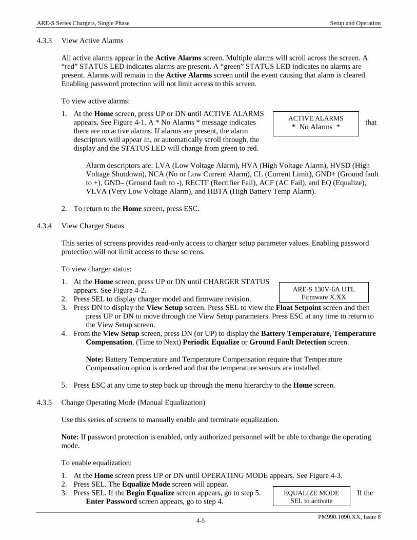
ARE-S Series Chargers, Single Phase Setup and Operation
PM990.1090.XX, Issue 8 4-5
4.3.3 View Active Alarms
All active alarms appear in the Active Alarms screen. Multiple alarms will scroll across the screen. A “red” STATUS LED indicates alarms are present. A “green” STATUS LED indicates no alarms are present. Alarms will remain in the Active Alarms screen until the event causing that alarm is cleared. Enabling password protection will not limit access to this screen. To view active alarms:
1. At the Home screen, press UP or DN until ACTIVE ALARMS appears. See Figure 4-1. A * No Alarms * message indicates that there are no active alarms. If alarms are present, the alarm descriptors will appear in, or automatically scroll through, the display and the STATUS LED will change from green to red.
Alarm descriptors are: LVA (Low Voltage Alarm), HVA (High Voltage Alarm), HVSD (High
Voltage Shutdown), NCA (No or Low Current Alarm), CL (Current Limit), GND+ (Ground fault to +), GND– (Ground fault to -), RECTF (Rectifier Fail), ACF (AC Fail), and EQ (Equalize), VLVA (Very Low Voltage Alarm), and HBTA (High Battery Temp Alarm).
2. To return to the Home screen, press ESC.
4.3.4 View Charger Status This series of screens provides read-only access to charger setup parameter values. Enabling password protection will not limit access to these screens. To view charger status:
1. At the Home screen, press UP or DN until CHARGER STATUS appears. See Figure 4-2.
2. Press SEL to display charger model and firmware revision. 3. Press DN to display the View Setup screen. Press SEL to view the Float Setpoint screen and then
press UP or DN to move through the View Setup parameters. Press ESC at any time to return to the View Setup screen.
4. From the View Setup screen, press DN (or UP) to display the Battery Temperature, Temperature Compensation, (Time to Next) Periodic Equalize or Ground Fault Detection screen.
Note: Battery Temperature and Temperature Compensation require that Temperature
Compensation option is ordered and that the temperature sensors are installed. 5. Press ESC at any time to step back up through the menu hierarchy to the Home screen.
4.3.5 Change Operating Mode (Manual Equalization)
Use this series of screens to manually enable and terminate equalization. Note: If password protection is enabled, only authorized personnel will be able to change the operating mode.
To enable equalization:
1. At the Home screen press UP or DN until OPERATING MODE appears. See Figure 4-3. 2. Press SEL. The Equalize Mode screen will appear. 3. Press SEL. If the Begin Equalize screen appears, go to step 5. If the
Enter Password screen appears, go to step 4.
ARE-S 130V-6A UTL Firmware X.XX
ACTIVE ALARMS * No Alarms *
EQUALIZE MODE SEL to activate

ARE-S Series Chargers, Single Phase Setup and Operation
PM990.1090.XX, Issue 8 4-6
4. At the Enter Password screen, press UP until your password is displayed and then press SEL. Go to step 5.
5. At the Begin Equalize screen, press one of the following: • Press SEL to select equalize mode. Go to step 6. • Press ESC to remain in float mode. Go to step 7. • Pressing UP or DN displays the Stay in Float Mode screen; press SEL to stay in float mode. Go
to step 7. 6. At the Equalize Duration screen, press UP or DN to set the duration (1-255 hours or Always
On). Press SEL to store the time. 7. Press ESC to step back up through the menu hierarchy to the Home screen.
To terminate equalization and return to float mode:
1. At the Home screen, press UP or DN until OPERATING MODE appears.
2. Press SEL. If the Equalize Mode screen at right appears, go to step If the Enter Password screen appears, go to step 3.
3. At the Enter Password screen, press UP until your password is displayed and then press SEL. Go to step 4.
4. At the Equalize Mode screen, press one of the following: • Press SEL to terminate (cancel) equalization and go to float
mode; go to step 5. • Press ESC to stay in equalize mode. Go to step 5. • Pressing UP or DN displays the Stay in Equalize Mode
screen; press SEL to stay in equalize mode. Go to step 5.
5. Press ESC to step back up through the menu hierarchy to the Home screen. 4.3.6 Alarm Relay/Lamp Test
This series of screens is used to test the alarm relays and Alarm LEDs. Since the alarm relays are being toggled (de-activated and activated), any attached annunciator (e.g. horn, siren, electronic messaging) will be toggled on and off. This test will produce an audible clicking as the relays are switched.
1. At the Home screen press UP or DN until OPERATING MODE appears. See Figure 4-3. 2. Press SEL. The present operating mode will be displayed. 3. Press DN. If the RELAY/LAMP TEST screen appears, go to step 5. If the Enter Password screen
appears, go to step 4. 4. At the Enter Password screen, press UP until your password is displayed and then press SEL. Go to
step 5. 5. Press SEL to begin the test. Testing will continue until ESC is pressed. 6. Press ESC to step back up through the menu hierarchy to the Home screen.
4.3.7 Change Charger Setup (Configuration) A default setup (i.e. configuration) is factory-installed. Table 4-1 lists the factory parameter values. Customer parameter values can be loaded if supplied with the order for the charger. Refer to the menu shown in Figure 4-4 when setting-up a newly installed charger or when changing the setup of an operating charger. The figure shows how to navigate the Charger Setup menu so that you can change operating parameters to accommodate your application. Note: If password protection is enabled, only authorized personnel will be able to change setup parameter values. When changing multiple values, you will be asked for your password only once during a charger setup session.
EQUALIZE MODE SEL to terminate
56.0VDC 1.7ADC Man. Equalize 24hrs left

ARE-S Series Chargers, Single Phase Setup and Operation
PM990.1090.XX, Issue 8 4-7
TABLE 4-1 Factory Default Setup Parameter Values
Some parameters are dependent upon optional features. For example, temperature compensation requires the installation of optional temperature sensors. Before setting up a charger determine which options are installed in the charger at hand. The procedures in this section are a bit more detailed than in the preceding sections. Consequently, several subsections are employed to simplify describing of the setup options available within this menu.
4.3.8 System Setpoints, System Alarms, and Summary Alarm The System Setpoints, System Alarms, and Summary Alarm menu selections, shown in Figure 4-4, are used to change setpoint voltages and currents, enable and disable system and summary alarms, set alarm delays, and adjust other parameter values. Guidelines for establishing values for some of these parameters are provided immediately below. Following the guidelines is a procedure for accessing and setting parameter values. The adjustment range of system setpoints will vary with charger voltage and current capacity.
4.3.9 Guidelines 4.3.9.1 Float and Equalize Voltages
Table 4-2 shows typical float and equalize voltages on a per cell basis for several types of batteries. Also refer to chapter 1 for the available ranges for configurable parameters.
CAUTION Refer to the battery manufacturer’s data sheet for the float and equalization setpoints that best fit your application and battery type. Do not set either float voltage or equalize voltage while the charger is operating in the current-limit mode. Disable battery temperature compensation before setting the float voltage.
ATTENTION Referez-vous à la fiche technique du fabricant de la batterie pour la tension d’entretien et d'égalisation qui correspondent le mieux à votre application et du type de batterie. Ne pas régler la tension d'entretien ou d’égalisation lors que le chargeur fonctionne en mode limite de courant. Désactiver la compensation de température de la batterie avant de régler la tension d’entretien.
4.3.9.2 Low Voltage Alarm (LVA)
Set the LVA alarm to a voltage that, if charger output voltage falls below this setting, an alarm will be annunciated.
Parameter 48 Vdc Models 130 Vdc Models Operating Mode (FL/EQ) Float Float Float Setpoint 52.8V 132.0V Equalization (EQ) 56.0V 140.0V Low Voltage Alarm (LVA) 48.0V 125.0V Very Low Voltage Alarm (VLVA) 46.6V 116.4V High Voltage Alarm (HVA) 58.0V 144.0V High Voltage Shutdown (HVSD) 60.0V 150.0V High Battery Temp Alarm (HBTA) 35 C (95 oF) 35 C (95 oF) Low Current Alarm (NCA/LCA) 2% of rating 2% of rating Current Limit (CL) 110% of rating 110% of rating Temperature Compensation Disabled Disabled AC Fail Equalize Disabled Disabled Periodic Equalize Disabled Disabled Load Share Disabled Disabled

ARE-S Series Chargers, Single Phase Setup and Operation
PM990.1090.XX, Issue 8 4-8
4.3.9.3 High Voltage Alarm (HVA) Set the HVA alarm to a voltage that, if charger output voltage goes above this setting, an alarm will be annunciated.
4.3.9.4 Primary (software) High Voltage Shutdown Voltage (HVSD) Set the HVSD alarm to a voltage that, if charger output voltage goes above this setting the charger will shutdown. If the charger output is maintained above this level for longer than the HVSD delay time (default 15 seconds; programmable) the charger will shutdown until the bus voltage falls below the setpoint. Afterward, the charger will attempt a self restart up to three (3) times. If the charger is able to restart the alarm will clear and the charger will return to normal operation. If the HVSD condition persists after the third restart the charger will remain in shutdown. To reset the primary HVSD the AC breaker must be toggled.
4.3.9.5 Secondary (hardware/software) High Voltage Shutdown (HVSD2) This safety feature is not programmable and is provided here for reference. A secondary or hardware HVSD is also provided that is independent of the primary HVSD. If a high voltage condition persists above the secondary HVSD setpoint (~2.66Vpc fixed) for more than 20 seconds (fixed) the SCRs will cease to fire, removing additional DC power from the bus. When the internal DC bus falls below approximately 12Vdc by opening the DC breaker, the ability to fire is returned to the SCRs; however, the SCRs will remained unfired by software control until the internal DC bus falls below 10Vdc and the user restarts the charger by pressing the SEL key as prompted by the charger. NOTE: If the charger is not equipped with a blocking diode the internal burden resistor may excessively discharge the battery. If a HVSD condition occurs prompt maintenance is recommended.
4.3.9.6 Current Limit Alarm (CL) Set the CL alarm to a voltage that, if charger output current goes above this setting, an alarm will be annunciated and charger output will be current limited to the CL value.
4.3.9.7 Low Current (No Charge) Alarm (LCA/NCA) Set the LCA/NCA alarm to a current that, if charger output current falls below this setting an alarm will be annunciated.
TABLE 4-2 Typical Float/Equalize Voltages Battery Type Float Equalize
Lead Antimony (1.210 Specific gravity) Lead Calcium (1.210 Specific gravity) Nickel Cadmium Nickel Iron Lead-Acid, Valve- Regulated (Sealed) (1.300 Specific gravity) (1.290 Specific gravity) (1.245 Specific gravity
2.15 – 2.17 2.17 – 2.25 1.43 1.50 – 1.55 2.25 – 2.30 2.25 – 2.30 2.17 – 2.22
2.33 2.33 1.55 1.60 – 1.65 ** ** **
* Equalize charge is required only if cells have experienced a discharge.

ARE-S Series Chargers, Single Phase Setup and Operation
PM990.1090.XX, Issue 8 4-9
Change Float Voltage Float = 52.8V
** Additional equalize charging is not recommended after initial charge equalization. Consult battery manufacturer for particular recommendations.
Note: Lead-calcium alloy grid batteries do not require regular equalizing. Set the
equalization voltage to equal the float voltage.
4.3.9.8 Rectifier Fail Alarm (RECTF)
Rectifier fail indicates the inability of the charger to maintain the desired float setpoint. This alarm will be active when any of the following alarms are also active: Low Voltage Alarm (LVA), High Voltage Alarm (HVA), High Voltage Shutdown (HVSD), Low/No Charge Alarm (LCA/NCA), and AC Fail Alarm (ACF).
4.3.10 Set Parameter Values
Parameters values accessed from the System Setpoints, System Alarms, and Summary Alarm screens are changed as follows.
1. From the Home screen press UP or DN until CHARGER SETUP appears. Press SEL. 2. From the System Setpoints screen, press one of the following:
• Press SEL to set system setpoint parameters. • Press UP or DN to move to another screen in the Setup Select Screens column. Then press SEL.
3. If a parameter screen appears, see example at right, go to step 5. If the Enter Password screen appears, go to step 4.
4. At the Enter Password screen, press UP until your password appears and then press SEL. Go to Step 5.
5. At the parameter screen, press UP or DN to display the parameter to be changed. Press SEL. • If changing a parameter value, the on-screen equals sign (=) will flash. Go to step 6. • To change Alarm Delays, again press SEL and go the step 6.
6. Press UP or DN until the desired value (e.g. setpoint voltage or current, enable or disable, alarm delay time) is displayed. Press one of the following:
• Press SEL to store the new value. The equals sign will stop flashing. • Press ESC to cancel or abort changes.
7. Press UP or DN to move vertically to the next value to be changed. 8. When all setup parameters have been set, press ESC to return to the higher level menu 9. As needed, repeat the above for each of the three setup select screens in this section. 10. When parameters have been set, press ESC until the Home screen appears. After returning to the
Home screen, the changed parameters will be stored to EEPROM and applied to the charger. 4.3.11 Battery Temperature Compensation
Temperature Compensation must installed for compensation to function.
1. From the Home screen, press UP or DN until CHARGER SETUP appears. Press SEL. 2. From the System Setpoints screen, press UP or DN until the Temperature Compensation screen
appears. 3. Press SEL. If the Battery Temperature Compensation Screen appears, go to step 5. If the Enter
Password screen appears, go to step 4. 4. At the Enter Password screen, press UP until your password appears and then press SEL. Go to Step
5. 5. At the Compensation disabled screen, press SEL. The equals sign (=) will begin to flash. 6. Press UP to toggle to “enable.” Press one of the following:
• Press SEL to store the change. The equals sign (=) will stop flashing. Go to step 7. • Press ESC to cancel or abort compensation. Go to step 10.
7. Press DN to display the Set Temperature Coefficient screen. 8. To change the coefficient, press SEL. The equals sign (=) will flash.
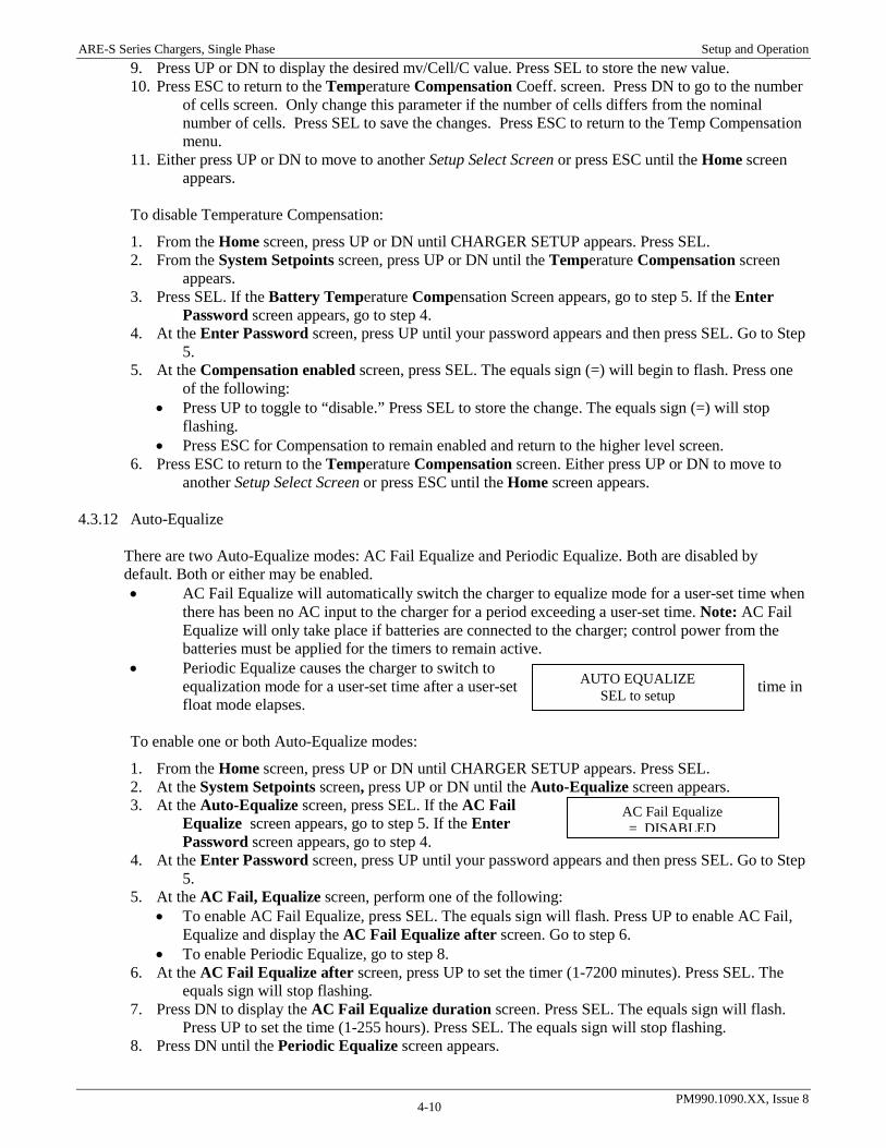
ARE-S Series Chargers, Single Phase Setup and Operation
PM990.1090.XX, Issue 8 4-10
AUTO EQUALIZE SEL to setup
AC Fail Equalize = DISABLED
9. Press UP or DN to display the desired mv/Cell/C value. Press SEL to store the new value. 10. Press ESC to return to the Temperature Compensation Coeff. screen. Press DN to go to the number
of cells screen. Only change this parameter if the number of cells differs from the nominal number of cells. Press SEL to save the changes. Press ESC to return to the Temp Compensation menu.
11. Either press UP or DN to move to another Setup Select Screen or press ESC until the Home screen appears.
To disable Temperature Compensation:
1. From the Home screen, press UP or DN until CHARGER SETUP appears. Press SEL. 2. From the System Setpoints screen, press UP or DN until the Temperature Compensation screen
appears. 3. Press SEL. If the Battery Temperature Compensation Screen appears, go to step 5. If the Enter
Password screen appears, go to step 4. 4. At the Enter Password screen, press UP until your password appears and then press SEL. Go to Step
5. 5. At the Compensation enabled screen, press SEL. The equals sign (=) will begin to flash. Press one
of the following: • Press UP to toggle to “disable.” Press SEL to store the change. The equals sign (=) will stop
flashing. • Press ESC for Compensation to remain enabled and return to the higher level screen.
6. Press ESC to return to the Temperature Compensation screen. Either press UP or DN to move to another Setup Select Screen or press ESC until the Home screen appears.
4.3.12 Auto-Equalize
There are two Auto-Equalize modes: AC Fail Equalize and Periodic Equalize. Both are disabled by default. Both or either may be enabled. • AC Fail Equalize will automatically switch the charger to equalize mode for a user-set time when
there has been no AC input to the charger for a period exceeding a user-set time. Note: AC Fail Equalize will only take place if batteries are connected to the charger; control power from the batteries must be applied for the timers to remain active.
• Periodic Equalize causes the charger to switch to equalization mode for a user-set time after a user-set time in float mode elapses.
To enable one or both Auto-Equalize modes:
1. From the Home screen, press UP or DN until CHARGER SETUP appears. Press SEL. 2. At the System Setpoints screen, press UP or DN until the Auto-Equalize screen appears. 3. At the Auto-Equalize screen, press SEL. If the AC Fail
Equalize screen appears, go to step 5. If the Enter Password screen appears, go to step 4.
4. At the Enter Password screen, press UP until your password appears and then press SEL. Go to Step 5.
5. At the AC Fail, Equalize screen, perform one of the following: • To enable AC Fail Equalize, press SEL. The equals sign will flash. Press UP to enable AC Fail,
Equalize and display the AC Fail Equalize after screen. Go to step 6. • To enable Periodic Equalize, go to step 8.
6. At the AC Fail Equalize after screen, press UP to set the timer (1-7200 minutes). Press SEL. The equals sign will stop flashing.
7. Press DN to display the AC Fail Equalize duration screen. Press SEL. The equals sign will flash. Press UP to set the time (1-255 hours). Press SEL. The equals sign will stop flashing.
8. Press DN until the Periodic Equalize screen appears.

ARE-S Series Chargers, Single Phase Setup and Operation
PM990.1090.XX, Issue 8 4-11
Periodic Equalize = DISABLED
• To enable Periodic Equalize, Press SEL. The equals sign will flash. Press UP to display enable Periodic Equalize and display the Periodic Equalize every screen. Go to Step 9.
• To exit Auto Equalize, go to step 11. 9. At the Periodic Equalize every screen, press UP to set the time (168 to 8760 hours). Press SEL. 10. Press DN to display the Periodic Equalize duration screen. Press SEL. The equals sign will flash.
Press UP to set the time (1-255 hours). Press SEL. 11. Press ESC to return to the Auto-Equalize screen. Either press UP or DN to move to another Setup
Select Screen or press ESC until the Home screen appears.
To disable AC Fail-Equalize:
1. At the Home screen, press UP or DN until CHARGER SETUP appears. Press SEL. 2. At the System Setpoints screen, press UP or DN until the Auto-Equalize screen appears. 3. At the Auto-Equalize setup screen, press SEL. The AC Fail Equalize after screen will appear. 4. Press SEL. The equals sign will flash. Press DN until DISABLED appears. Press SEL. 5. Press ESC to return to the Auto-Equalize screen. Either press UP or DN to move to another Setup
Select Screen or press ESC until the Home screen appears.
To disable Periodic Equalize:
1. At the Home screen, press UP or DN until CHARGER SETUP appears. Press SEL. 2. At the System Setpoints screen, press UP or DN until the Auto-Equalize screen appears. 3. At the Auto-Equalize setup screen, press SEL. Press UP or DN until the Periodic Equalize screen
appears. 4. Press SEL. The equals sign will flash. Press DN until DISABLED appears. Press SEL. 5. Press ESC to return to the Auto-Equalize screen. Either press UP or DN to move to another Setup
Select Screen or Press ESC until the Home screen appears.
4.3.13 Load Share CAUTION For Issue 1A Control/Display boards (306.2993.00), Load share Repeater/Isolator board (306.2988.00) are required for proper functionality; DO NOT connect load share jacks without proper equipment.
ATTENTION Pour le contrôleur / panneaux d'affichage ‘Issue 1A’ (306.2993.00), ‘Repeater/Isolator Board’ (306.2988.00) est nécessaire pour la fonctionnalité adéquate; NE PAS connecter le partage de courant sans l’équipement adéquat.
Note: Legacy load share is not supported with the ARE-S.
Load share is a digital communication protocol between a “master” charger and up to 4 “subordinate” chargers that allows two or more ARE-S Series units connected in parallel to share the DC load in proportion to their ratings. The chargers will share the system load and battery recharge demand proportionally within 10% of the individual charger ratings. 4.3.13.1 Field Connection and Setup of Load share For load sharing, connect all units, which are to share the load to the DC system bus using equal lengths of properly sized cables for the system load as determined in Table 2-1. Specific to each individual application and system specifications, additional considerations for long cable runs and allowable voltage drop should also be accounted for. Communication connections for load share are made on the control display boards of each charger using standard CAT5e ethernet cable. For issue 1A control boards, an isolator/repeater circuit board (p/n 306.2988.00) is required for proper operation; DO NOT connect the load sharing ports of a charger with an issue 1A control

ARE-S Series Chargers, Single Phase Setup and Operation
PM990.1090.XX, Issue 8 4-12
board without the isolator board. Doing so may cause undesired charger operation or cause failure of the charger and components. The load share repeater board is not required for issue 2 control boards and later. See the following figures for an easy visual check on the control board version. Contact field service for help with determining your board revision or load share connections if necessary.
FIGURE 4-5 ISSUE 1 CONTROL BOARD (NOT LOAD SHARE COMPATIBLE)
FIGURE 4-6 ISSUE 1A BOARD (REQUIRES 306.2988.00 ISOLATOR BOARD)
FIGURE 4-7 ISSUE 2, 2A OR LATER BOARD (LOAD SHARE READY) If only two (2) chargers are used, modify the number of chargers accordingly in each charger from the figure shown. If the charger is first or last in the load share chain be sure to set the End of Line (EOL) jumper shunt to the “Y” position on the back of the control board (see figures below).

ARE-S Series Chargers, Single Phase Setup and Operation
PM990.1090.XX, Issue 8 4-13
FIGURE 4-8 2-CHARGER LOAD SHARE SETUP EXAMPLE
FIGURE 4-9 3-CHARGER LOAD SHARE SETUP EXAMPLE
Master Charger Load share Settings: EOL = Y Address = 1 # of Chgrs = 2
J3-Next Charger
J4-Prev Charger
Ctrl/Display Brd 306.2993.00
Sub Charger Load share Settings: EOL = Y Address = 2 # of Chgrs = 2
Ctrl/Display Brd 306.2993.00
Isolator/Repeater Board 306.2988.00
(Use with ISS 1A boards only)
Cat5e Cat5e
Master Charger Load share Settings: EOL = Y Address = 1 # of Chgrs = 3
J3-Next Charger
J3-Next Charger
J4-Prev Charger
J4-Prev Charger
Ctrl/Display Brd 306.2993.00
Sub Charger #1 Load share Settings: EOL = N Address = 2 # of Chgrs = 3
Sub Charger #2 Load share Settings: EOL = Y Address = 3 # of Chgrs = 3
Ctrl/Display Brd 306.2993.00
Ctrl/Display Brd 306.2993.00
Isolator/Repeater Board 306.2988.00
(Use with ISS 1A boards only)
Cat5e Cat5e Isolator/Repeater Board 306.2988.00
(Use with ISS 1A boards only)
Cat5e Cat5e

ARE-S Series Chargers, Single Phase Setup and Operation
PM990.1090.XX, Issue 8 4-14
LOAD SHARE = DISABLED
LOAD SHARE Charger Addr. = 1
LOAD SHARE # of Chgrs = 3
FIGURE 4-10 EOL (END OF LINE) JUMPER (ISSUE 2A BOARD SHOWN)
Note: EOL jumper location may vary on other board issues.

ARE-S Series Chargers, Single Phase Setup and Operation
PM990.1090.XX, Issue 8 4-15
132.0Vdc 25.0A Float - LS
FIGURE 4-11 LOAD SHARE CONFIGURATION MENU SCREENS
To enable Load Share from the front panel:
1. From the Home screen, press UP or DN until CHARGER SETUP appears. Press SEL. 2. From the Load Share screen press SEL. The Load Share Disabled screen will appear. 3. Press DN twice to go to the # of Chargers screen. Press SEL and then press UP or DN to change the
number of chargers to the total number of chargers that will be loadsharing. 4. Press ESC to return to the # of Chargers screen 5. Press UP to display the Charger Address screen: press SEL and then UP to change the charger
address. Press SEL to save the new charger address. The default address is address 0 - load share disabled. The master charger MUST BE address 1; subordinate chargers should range from 2-5 in order. Each charger MUST have a unique address. Only one master charger is allowed.
6. Press ESC to return to the Load share Address screen. 7. Press SEL to save the change and then return to the Load Share enable screen. 8. Set up the remaining chargers appropriately. 9. After all the chargers have been configured and connected properly, enable the load share on the
subordinate chargers and then enable the load share on the master charger. The chargers should start to proportionally share the load based upon the charger ratings and number of chargers.
To disable Load Share:
1. At the Load Share screen press SEL. The Load Share Enabled screen will appear. 2. Press SEL and then press DN until DISABLED appears. 3. Press SEL to store the new status and go to the Load Share screen. Either press UP or DN to move to
another Setup Select Screen or Press ESC until the Home screen appears. As proper practice, the Number of Chargers and the Charger Address should be set to 0 if Load share is not to be used.
4.3.13.2 Activating load share
A. Turn on all units. Setup the load share settings with the proper addresses and number of chargers on each charger as shown above.
B. Enable load share on the subordinate chargers then enable load share on the master charger.
C. The chargers should start sharing load proportionally according to their rated output and the total system capacity. Additionally, the home screen should show a LS suffix if load share has been enabled.
FIGURE 4-12 HOME SCREEN DURING ACTIVE LOADSHARING 4.3.13.3 Operational Notes
1. Load sharing is not intended to be effective below 10% of the combined rated output. Operation below 10% may result in unequal outputs or loss of output current form one of the units (NCA/LCA – No/Low Charge Alarm). It is recommended that where paralleled units are being used to float a battery before the system load is installed, only one unit be left operating. The units are expected to share acceptably below 10% load, but this is not guaranteed.
2. Minor changes in the displayed output current may occur on paralleled units. This is an indication of the transfer of small currents between units and does not show up at the load.

ARE-S Series Chargers, Single Phase Setup and Operation
PM990.1090.XX, Issue 8 4-16
3. If chargers have different current ratings it is suggested that the master charger be the largest in the chain. This should provide adequate capacity to prevent the master charger from going into a current limit state under a subordinate charger removal or loss of load share. See Operational Note 5.
4. Loss of the master charger by any mechanism such as AC Fail, DC breaker open, rectifier fail, or loss of communications with the master charger will result in the subordinate chargers returning to float mode. When the chargers are in float mode they will passively share the load. The degree to which the units will passively load share will depend on the accuracy of the calibration between units; neither proportional nor equivalent load share is guaranteed under passive load share.
5. Loss of a subordinate charger will result in the master charger assuming all load from the failed subordinate charger. i.e. the load will NOT be redistributed between the remaining active chargers. See Operational Note 3.
6. As long as the chargers do not lose control power (i.e. batteries are connected) the chargers should auto-recover from any load share failure mechanism such as an AC Fail, DC breaker open, loss of communications, etc. Loss of control power will require that load share be re-enabled by the user at the front panel of all chargers in the load share chain. It is necessary to re-verify all load share settings on all chargers – # of chargers, charger address, and enabled load share – after a loss of control power.
7. Load share communications cables are standard CAT5e cables. Max cable length: 30m.
8. The End of Line (EOL) jumpers must be set to “Y” on the first charger and the last charger in the chain. The EOL jumper should be set to “N” on any charger in the middle of a chain. If a charger is not connected in a load share chain the EOL jumper should be set to “Y”.
9. If temperature compensation is to be used in load share, it MUST be enabled on all chargers in the load share chain. The temperature sensors for all chargers should be connected to the same point on the battery string. Failure to enable the temperature compensation or connect the temperature sensors to the same point may prevent the chargers from load sharing properly and/or prevent the chargers from recovering from a failure or no (low) charge situation.
10. If any charger in the load share chain is equipped with the blocking diode option, all chargers in the load share chain should be equipped with a blocking diode. Failure to do so may prevent chargers from sharing load properly and/or recovering from a load share failure or no (low) charge situation.
11. During any Equalize mode the chargers should continue to share the load proportionally when configured properly. Only the master charger should have an Auto-Equalize mode (AC Fail EQ or Periodic EQ) enabled. The master charger will direct the subordinate chargers to follow into equalize mode. A remote equalize (REM EQ) or a manual equalize (MAN EQ) should be directed from the master charger. All equalize modes should be disabled on the subordinate chargers.
4.3.14 Password
Password protection allows only authorized personnel to change parameter values in the Operating Mode menu (Figure 4-3) and Charger Setup menu (Figure 4-4). While password protection is disabled by default, enabling password protection is recommended. Anyone with access to the charger operator panel can view alarms and parameter values in the Active Alarms screen and the Charger Status menu (Figure 4-2). Password protection is not needed since these are read-only displays. When password protection is enabled, you will be asked for your password only once during a setup session, regardless of the number of setup changes made. After 5-6 minutes of no keypad activity, your setup session will time-out and you will again be asked for your password to change a parameter value. Any number between 00002 and 65500 can be used as the password. Select a password that is easy to remember but difficult for others to guess. As with any password, secrecy is required for meaningful security. If the password is forgotten, contact UNIPOWER Field Service.
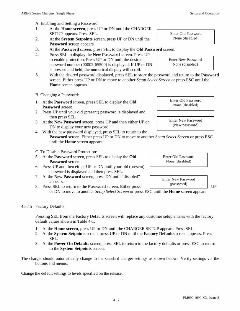
ARE-S Series Chargers, Single Phase Setup and Operation
PM990.1090.XX, Issue 8 4-17
A. Enabling and Setting a Password: 1. At the Home screen, press UP or DN until the CHARGER
SETUP appears. Press SEL. 2. At the System Setpoints screen, press UP or DN until the
Password screen appears. 3. At the Password screen, press SEL to display the Old Password screen. 4. Press SEL to display the New Password screen. Press UP
to enable protection. Press UP or DN until the desired password number (00002-65500) is displayed. If UP or DN is pressed and held, the numerical display will scroll.
5. With the desired password displayed, press SEL to store the password and return to the Password screen. Either press UP or DN to move to another Setup Select Screen or press ESC until the Home screen appears.
B. Changing a Password:
1. At the Password screen, press SEL to display the Old Password screen.
2. Press UP until your old (present) password is displayed and then press SEL.
3. At the New Password screen, press UP and then either UP or DN to display your new password.
4. With the new password displayed, press SEL to return to the Password screen. Either press UP or DN to move to another Setup Select Screen or press ESC until the Home screen appears.
C. To Disable Password Protection: 5. At the Password screen, press SEL to display the Old
Password screen. 6. Press UP and then either UP or DN until your old (present)
password is displayed and then press SEL. 7. At the New Password screen, press DN until “disabled”
appears. 8. Press SEL to return to the Password screen. Either press UP
or DN to move to another Setup Select Screen or press ESC until the Home screen appears.
4.3.15 Factory Defaults Pressing SEL from the Factory Defaults screen will replace any customer setup entries with the factory default values shown in Table 4-1.
1. At the Home screen, press UP or DN until the CHARGER SETUP appears. Press SEL. 2. At the System Setpoints screen, press UP or DN until the Factory Defaults screen appears. Press
SEL. 3. At the Power On Defaults screen, press SEL to return to the factory defaults or press ESC to return
to the System Setpoints screen. The charger should automatically change to the standard charger settings as shown below. Verify settings via the
buttons and menus.
Change the default settings to levels specified on the release.
Enter Old Password None (disabled)
Enter New Password None (disabled)
Enter Old Password None (disabled)
Enter New Password (password)
Enter Old Password None (disabled)
Enter New Password (New password)
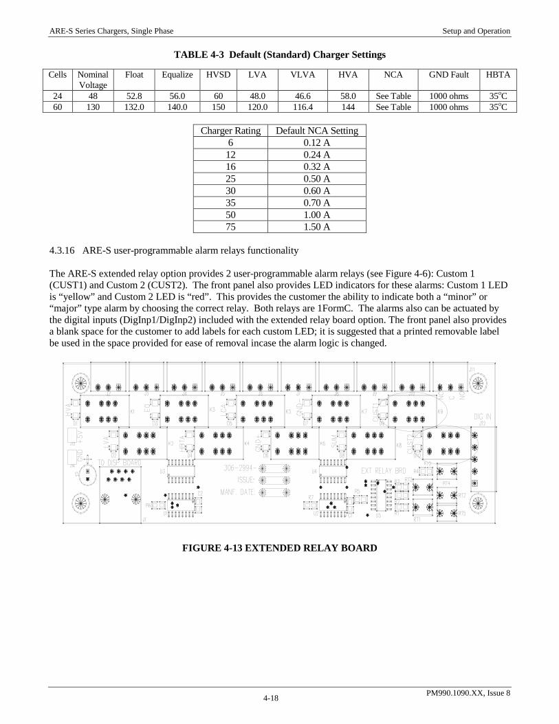
ARE-S Series Chargers, Single Phase Setup and Operation
PM990.1090.XX, Issue 8 4-18
TABLE 4-3 Default (Standard) Charger Settings
Charger Rating Default NCA Setting
6 0.12 A 12 0.24 A 16 0.32 A 25 0.50 A 30 0.60 A 35 0.70 A 50 1.00 A 75 1.50 A
4.3.16 ARE-S user-programmable alarm relays functionality The ARE-S extended relay option provides 2 user-programmable alarm relays (see Figure 4-6): Custom 1 (CUST1) and Custom 2 (CUST2). The front panel also provides LED indicators for these alarms: Custom 1 LED is “yellow” and Custom 2 LED is “red”. This provides the customer the ability to indicate both a “minor” or “major” type alarm by choosing the correct relay. Both relays are 1FormC. The alarms also can be actuated by the digital inputs (DigInp1/DigInp2) included with the extended relay board option. The front panel also provides a blank space for the customer to add labels for each custom LED; it is suggested that a printed removable label be used in the space provided for ease of removal incase the alarm logic is changed.
FIGURE 4-13 EXTENDED RELAY BOARD
Cells Nominal Voltage
Float Equalize HVSD LVA VLVA HVA NCA GND Fault HBTA
24 48 52.8 56.0 60 48.0 46.6 58.0 See Table 1000 ohms 35oC 60 130 132.0 140.0 150 120.0 116.4 144 See Table 1000 ohms 35oC

ARE-S Series Chargers, Single Phase Setup and Operation
PM990.1090.XX, Issue 8 4-19
FIGURE 4-14 FRONT PANEL CUSTOM LEDS
4.3.17 User-programmable Alarm Relays Setup and Operation
The alarm relays are configured under the CHARGER SETUP menu; the setup of both alarms is identical. Each relay can be assigned a single alarm to be actuated from or a logical OR or logical AND combination of the available alarm conditions. If the NONE logical expression is selected the relay will be disabled. The following menu structure illustrates the setup of the relays. To enable the custom alarms, select the desired logic operation and then add the desired alarms by enabling them in the sub-menu.
TABLE 4-4 Custom Setup Menu Tree Level 1 Level 2 Level 3 Level 4 Level 5 Main Menu
Charger Setup
Custom Alarms Setup Press SEL to setup
Custom 1 DISABLED(ENABLED) Press SEL to setup
Boolean Logic Exp1(2)= NONE/AND/OR
Custom 2 DISABLED(ENABLED) Press SEL to setup
Custom 1(2) Alarms ACF= DISABLED(ENABLED)
Custom 1(2) Alarms HVSD= DISABLED(ENABLED)
Custom 1(2) Alarms HVA= DISABLED(ENABLED)
Custom 1(2) Alarms LVA= DISABLED(ENABLED)
Custom 1(2) Alarms VLVA= DISABLED(ENABLED)
Custom 1(2) Alarms EQ= DISABLED(ENABLED)
Custom 1(2) Alarms HBTA= DISABLED(ENABLED)
Custom 1(2) Alarms LCA= DISABLED(ENABLED)
Custom 1(2) Alarms GND+= DISABLED(ENABLED)
Custom 1(2) Alarms GND–=DISABLED(ENABLED)
Custom 1(2) Alarms CL= DISABLED(ENABLED)
Custom 1(2) Alarms DigInp1= DISABLED(ENABLED)
Custom 1(2) Alarms DigInp2= DISABLED(ENABLED)

ARE-S Series Chargers, Single Phase Setup and Operation
PM990.1090.XX, Issue 8 4-20
The digital inputs (DigInp1 and DigInp2) can be included in the logical function of either relay. A dry contact relay closure is to be used to from the COM input to the digital input to provide the logic low signal to actuate the appropriate relay and LED.
FIGURE 4-15 DIGITAL INPUTS 4.3.18 Factory Calibration Factory Calibration is intended for use by factory personnel and is not field accessible. Contact UNIPOWER Field Service for additional information. 4.3.19 Field Calibrations No calibration settings are field adjustable. All other field adjustments are described previously in this chapter.

ARE-S Series Chargers, Single Phase Circuit Description
PM990.1090.XX, Issue 8 5-1
5. CIRCUIT DESCRIPTION Figure 5-1 is a functional block diagram of a ARE-S series float charger. AC input power is applied through the input circuit breaker to the power transformer. The circuit breaker provides over-current and fault protection in case of malfunction or a short circuit in the input side of the equipment.
Single-PhaseAC Input
ACCircuit
Breaker
Power Transformer
ElectronicVoltage & Current
Control
High VoltageShutdown
SCR Rectifiers TriggerCircuitry
DC Filter
Operator PanelAlarms LEDs
Battery and Load
Control and Display Board
DC Circuit Breaker
Interface Board
STD Alarm Relays
OPT Alarm Relays
Optional Relay Board
FIGURE 5-1 BLOCK DIAGRAM, TYPICAL ARE-S FLOAT CHARGER The output voltage regulation against changes in load, line input levels, and frequency changes is provided by a half-controlled SCR bridge rectifier, which controls the voltage output to the DC filter. The electronic voltage/current control senses the start of the AC cycle. It also senses the output voltage level, which it compares with a reference setpoint. The error signal that results determines the instant to fire the SCRs during the AC cycle and maintain the DC output level. The output current sensing and current limit operation is located on the Interface and Control/Display boards. The output current is sensed by measuring the voltage across a resistive shunt. The Interface and Control/Display boards convert the shunt signal into an output current value. When the output current exceeds the preset level, the current limit control overrides the voltage control to reduce the output current to the preset value. Over-voltage protection is located on the Interface and Control/Display boards. If a fault occurs that result in the charger output going to an excessively high output voltage for more than 15 seconds, a “primary” high voltage shutdown is initiated. The high voltage shutdown mode will cease firing the SCRs, which will turn off the output to the charger. The charger will attempt to restart up to 3 times if the output falls below a safe level. If the excessive high voltage condition persists the charger will shutdown until the AC breaker is toggled. If the high voltage persists above a safe level for more than ~20 seconds, a second protection circuit, independent from the first, operates to remove triggering of the SCRs turning off the charger. To reset this “secondary HVSD” the DC breaker must be opened and the internal DC bus must fall below 10Vdc. The user must then restart the charger using the SEL key on the front panel. The SCR rectifiers convert the AC voltage from the transformer into a DC voltage. The output of the rectifiers is filtered and supplied to the battery and the load through the DC circuit breaker.
ARE-S Series Chargers, Single Phase Circuit Description
PM990.1090.XX, Issue 8 5-2
The front panel consists of a 2-line digital display, a 4-button keypad, and LEDs. The display and LEDs are mounted directly to the Control and Display Board. Alarm connections for external annunciation of alarms are provided on the Interface Board and an optional Extended Alarm Relay Board. The Interface Board has three (3) standard alarm relays and the Extended Alarm Board has ten (10) alarm relays. All outputs are form C relays. Each relay has three connections: common, normally open, and normally closed. The normally open (NO) and normally closed (NC) labels are for an un-powered charger (de-energized state).

ARE-S Series Chargers, Single Phase Maintenance
PM990.1090.XX, Issue 8 6-1
6. MAINTENANCE This chapter provides preventive maintenance procedures and troubleshooting procedures. Cabinet assembly drawings, schematics, and parts lists for all standard charger models are included in this chapter. Refer to the replacement parts lists in the PN drawing that accompanies you charger when ordering on-hand spare parts and service replacement parts.
WARNING Electrical shock hazard Hazardous voltage can cause death or serious injury. Remove AC input power before servicing. Always use insulated tools. Disconnect battery string before servicing. Battery voltage is on the Interface Board whenever a battery string is connected.
AVERTISSEMENT Risque de choc électrique Les tensions dangereuses peuvent causer la mort ou des blessures graves. Coupez l'alimentation de tous les fils et les bornes avant de travailler sur les équipements. Toujours utiliser des outils isolés. Débranchez la batterie avant l'entretien. La tension de la batterie se retrouve sur la carte d'interface quand la batterie est branchée.
WARNING Arcing hazard Arcing can cause equipment damage, load interruptions, and personal injury. Remove watch and jewelry. Use insulated tools and extreme caution when working with a battery string. Disconnect the battery string before servicing. Carefully insulate unterminated battery cable ends. Discharge filter capacitors before servicing.
AVERTISSEMENT Risque d'arc Un arc électrique peut causer des dommages sur les équipements, des interruptions de charge, et des blessures. Retirez vos montres et bijoux utilisés des outils isolés et une prudence extrême lorsque vous travaillez avec des batteries. Débranchez la batterie avant l'entretien. Isoler les extrémités des câbles de batterie. Décharger les condensateurs avant l'entretien.
6.1 PREVENTIVE
1. Ensure that a generous supply of cool, dry air is free to circulate through the charger. See Chapter 2 Installation.
2. Clean the equipment. Dust and dirt impede heat dissipation. Blow out the charger with low-pressure dry air to remove accumulated dust, dirt and any other contaminants.
3. Check that all connections are clean and tight. Discoloration of terminals or wires is an indication of loose or corroded connections.
4. Check capacitors DC for leakage, case or seal rupture, etc. All screw connections should be checked and tightened as needed. DC capacitors over five years old or showing signs of degradation should be removed and checked for excessive leakage current and low capacitance. If the capacitors cannot be tested, they should be replaced.
5. Check the float voltage, equalize voltage, and other configurable settings, using the front panel controls. See Chapter 4 Setup and Operation.

ARE-S Series Chargers, Single Phase Maintenance
PM990.1090.XX, Issue 8 6-2
6.2 TROUBLESHOOTING Table 6-1 is a troubleshooting chart designed to help a qualified technician diagnose the cause of a charger malfunction. While troubleshooting, refer to the cabinet assembly drawing and the schematic diagram for the charger model at hand. These aids can be found in this chapter. Also provided is a section describing the testing of various electrical components. For efficient troubleshooting, gather as much information as possible about the malfunction.
1. Read the front panel display and note charger output voltage and current
2. Note whether the front panel STATUS and Alarm LEDs are lit
3. Note whether the AC or DC breaker trips or has been tripped
4. Measure the AC source voltage, and frequency
5. Check AC, DC, and alarm wiring
6. Check configurable parameter values to be sure an unintended setup change is not interfering with equipment operation
7. Note environmental conditions before and at the time of the malfunction (e.g. excessive ambient temperature, water intrusion, excessive foreign material accumulated on heat sensitive components)
8. Review the equipment’s service history After gathering data concerning the malfunction, scan the symptoms in the left column of the Troubleshooting Chart, Table 6-1. When the observed symptom is located, read across the table for a possible cause and solution. The circuits and functions on the Control and Display board and the Interface board are highly integrated making it difficult to isolate a problem to one of these boards. Board replacement is recommended to repair a control or display related problem. 6.2.1 Service Access For access to the Interface board, Control and Display board, AC and DC circuit breakers, and connection terminal blocks, loosen two captive screws and open the hinged front panel. To replace a component inside the charger, such as the transformer or a filter capacitor, remove the top cover. Additional access is provided on 12" cabinets by removing the interface board panel. 6.2.2 Circuit Board Handling Semiconductors such as ICs (integrated circuits), diodes, and transistors must be protected against damaging electrostatic discharge. A properly grounded wrist strap must be worn whenever a circuit board is handled or touched. A service kit with a wrist strap and static dissipative work mat is available from both mail order and local electronic supply companies. Always store circuit boards in anti-static bags.

ARE-S Series Chargers, Single Phase Maintenance
PM990.1090.XX, Issue 8 6-3
6.2.3 ARE-S LCD Display Codes The charger operating state will toggle on the 2nd line of the LCD display with the active alarms. The active alarms will continue to toggle until any key on the front panel is pressed acknowledging that the alarms have been viewed by a user. Once acknowledged the display will only show the present operating state. The active alarms can always be viewed under the CHARGER STATUS menu. Charger State Codes Description Start Displays anytime charger resets and starts increasing the output voltage to the set point.
The charger will increase the output voltage in discrete steps; these may be noticeable if the charger is started/reset under increased load conditions.
Float The normal operating state of the charger. Constant voltage control mode designed to
“float” charge the batteries. The charger will supply current to the system load and batteries up to the current limit setpoint.
Float – LS The charger is operating in float mode with load share enabled. Current Limit The charger is holding the output current at the current limit set point and the voltage is
below the output voltage set point. This code could be produced by a large load current, or deeply discharged batteries.
Equalize The charger output is increased (usually temporarily) to the Equalize setpoint. The
charger will operate under constant voltage mode up to the current limit setpoint. Equalize mode is sometimes employed to “equalize” the individual cell voltages in a battery string. Refer to the battery manuals for whether the battery string should be equalized and the corresponding voltage setpoint and duration.
Equalize – LS The charger is operating in equalize mode with load share enabled. Remote Equalize The charger’s external equalization input is shorted, so the charger is in put into
Equalization mode. The charger will remain in Remote Equalize until the activating control input is removed.
AC Fail Equalize The charger has been put into equalize mode that was triggered by a corresponding AC
Fail event. The equalize time remaining will also be shown. The charger will remain in equalize mode until the AC Fail equalize timer expires. Set AC Fail trigger timer and duration from the AC Fail Equalize menu under the CHARGER SETUP menu.
Periodic Equalize The charger can be set to enter equalize mode periodically. The equalize time remaining
will also be shown. Set up the period and duration from the Periodic Equalize menu under the CHARGER SETUP menu.
Manual Equalize The charger can be set to equalize mode for a fixed duration from the front panel. The
equalize time remaining will also be shown. Enable manual equalize and the manual equalize duration from the OPERATING MODE menu.
HIGH VOLTAGE SHUTDOWN The charger voltage sense was above the High Voltage Shutdown (HVSD) set point for
more than 15 seconds (default HVSD delay). The charger went into a high voltage shutdown mode to protect the battery and the load(s). Also known as a “primary” high voltage shutdown. The AC breaker of the charger must be cycled to reset a primary HVSD.
SECONDARY HVSD The interface board has initiated a HVSD command because the internal bus was over the
secondary HVSD level for more than 20 seconds. The chargers internal DC bus must be allowed to discharge by opening the DC breaker after which the SEL key must be pressed to restart the charger.
PRESS SEL TO RESTART The charger can be reset from a High Voltage Shutdown mode from the keypad by
pressing the SEL button. AC Fail (ACF) No AC line input to the charger is currently being detected.

ARE-S Series Chargers, Single Phase Maintenance
PM990.1090.XX, Issue 8 6-4
Charger Alarm Codes Description ACF AC Fail – The charger does not detect incoming AC voltage. The utility supply to the
charger is unavailable (power outage), the breaker at the customer service panel is off/tripped, the charger’s AC breaker is off/tripped, or an interface board failure has occurred.
LVA Low Voltage Alarm – The DC bus has fallen below the LVA setpoint for a duration that
is longer than the LVA delay setting. HVA High Voltage Alarm – The DC bus has risen above the HVA setpoint for a duration that
is longer than the HVA delay setting. HVSD High Voltage Shutdown – The charger is in the High Voltage Shutdown state. LCA Low Charge Alarm – Synonymous with NCA (No Charge Alarm). The charger is not
outputting current above the NCA/LCA setpoint. Set to 20% of charger output rating by default.
NCA No Charge Alarm – Synonymous with LCA (Low Charge Alarm). The charger is not
outputting current above the NCA/LCA setpoint. Set to 20% of charger output rating by default.
OC Over-Current – Synonymous with Current Limit (CL). The charger has exceeded the
current limit setting. Set to 110% of charger output rating by default. GND+ Positive Ground Fault – The resistance between the charger’s internal positive bus and
chassis ground has fallen below the ground fault resistance threshold. Indicates low resistance or excessive leakage current between the positive bus, battery terminals, or cabling and chassis/earth ground.
GND- Negative Ground Fault – The resistance between the charger’s internal negative bus and
chassis ground has fallen below the ground fault resistance threshold. Indicates low resistance or excessive leakage current between the negative bus, battery terminals, or cabling and chassis/earth ground.
RECTF Rectifier Fail – Indicates a charger alarm condition or failure of the charger/rectifier to
provide the proper voltage required. Rectifier Fail is hard coded to be active under any of the following conditions: LVA, HVA, HVSD, LCA/NCA, or ACF
VLVA Very Low Voltage Alarm – The DC bus voltage has dropped below the VLVA setpoint
for a duration that is longer than the VLVA delay setting. EQ Equalize – The charger is in equalize mode. This is not necessarily an alarm as it may be
due to expected operation; however, an alarm status/code is annunciated as this is not the nominal operating state.
HBTA High Battery Temperature Alarm – (if equipped with temperature compensation) The
battery temperature acquired by the temperature sensor is above the high battery temperature threshold.

ARE-S Series Chargers, Single Phase Maintenance
PM990.1090.XX, Issue 8 6-5
TABLE 6-1 Troubleshooting Chart
Symptom Possible Cause(s) Solution(s) A. AC breaker trips 1. Short circuit in AC power circuit Inspect primary wiring for possible shorts or
grounded connections. 2. Input connected for lower voltage. a. Check position of jumpers. Consult connection
diagram. b. Measure input voltage. 3. SCR module fail shorted. Check SCR module for low resistance. Diode check
SCR module. Contact field service for SCR Module replacement.
4. Input voltage outside ANSI range. Measure input voltage. 5. Frequency of supply less than
57Hz. Check input frequency.
6. Short in transformer winding. Visually inspect power transformer primary coils for signs of overheating.
B. No DC output 1. AC power outage. Check for AC voltage on both sides of breaker. 2. Short circuit in DC power circuit. a. Inspect secondary power wiring and terminals for
shorts or grounded connections. b. Check SCRs. c. Check for shorted DC filter capacitors. 3. Open circuit. Check all wiring for open or loose connections. 4. Secondary HVSD operating Check LCD for confirmation. Open DC breaker.
Allow internal DC bus to discharge. Press SEL to restart charger when prompted. Close DC breaker when bus has stabilized.
5. Primary HVSD is operating Cycle AC breaker to restart charger. 6. Interface/Control Firmware
Mismatch Contact Field Service for boards with correct FW.
C. Low DC output voltage 1. Unit out of calibration. Check voltage at DC terminals with voltmeter. Contact field service.
2. Open sensing leads. Check wiring for continuity. 3. Unit in current limit. a. Adjustment current limit setting. b. Reduce load. c. Verify correct unit type settings on interface board. 4. Component failure in interface
board. Replace interface board.
5. Component failure in control board. Replace control board. 6. One SCR module not triggering. Check trigger harnesses for continuity. Check for
trigger pulses. 7. Out of adjustment. Adjust float voltage. 8. Input connected for higher voltage Check input connection jumpers. Consult connection
diagram. D. High DC output voltage. 1. SCR module self-triggering. a. Replace SCR module. b. Reduce ambient operating temperature. 2. Open sensing leads. Check for DC voltage across control board pins J19-
1 and J19-3 3. Interface board failure. Replace interface board. 4. Control board failure. Replace control board. 5. Unit out of calibration. Check voltage at DC terminals with voltmeter.
Contact field service. 6. Charger is in Equalize. Set charger to float mode.
7. Interface/Control Firmware
Mismatch Contact Field Service for boards with correct FW.
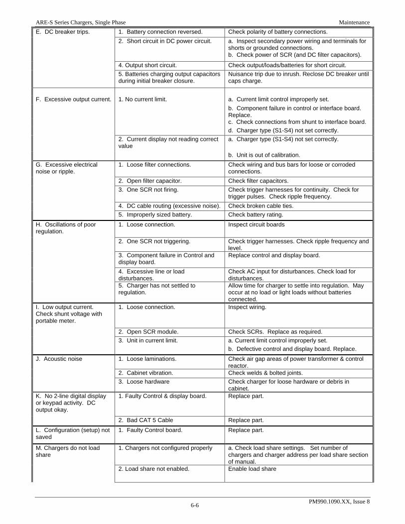
ARE-S Series Chargers, Single Phase Maintenance
PM990.1090.XX, Issue 8 6-6
E. DC breaker trips. 1. Battery connection reversed. Check polarity of battery connections. 2. Short circuit in DC power circuit. a. Inspect secondary power wiring and terminals for
shorts or grounded connections. b. Check power of SCR (and DC filter capacitors).
4. Output short circuit. Check output/loads/batteries for short circuit. 5. Batteries charging output capacitors
during initial breaker closure. Nuisance trip due to inrush. Reclose DC breaker until caps charge.
F. Excessive output current. 1. No current limit. a. Current limit control improperly set. b. Component failure in control or interface board.
Replace. c. Check connections from shunt to interface board. d. Charger type (S1-S4) not set correctly. 2. Current display not reading correct
value a. Charger type (S1-S4) not set correctly.
b. Unit is out of calibration. G. Excessive electrical noise or ripple.
1. Loose filter connections. Check wiring and bus bars for loose or corroded connections.
2. Open filter capacitor. Check filter capacitors. 3. One SCR not firing. Check trigger harnesses for continuity. Check for
trigger pulses. Check ripple frequency. 4. DC cable routing (excessive noise). Check broken cable ties. 5. Improperly sized battery. Check battery rating. H. Oscillations of poor regulation.
1. Loose connection. Inspect circuit boards
2. One SCR not triggering. Check trigger harnesses. Check ripple frequency and level.
3. Component failure in Control and display board.
Replace control and display board.
4. Excessive line or load disturbances.
Check AC input for disturbances. Check load for disturbances.
5. Charger has not settled to regulation.
Allow time for charger to settle into regulation. May occur at no load or light loads without batteries connected.
I. Low output current. Check shunt voltage with portable meter.
1. Loose connection. Inspect wiring.
2. Open SCR module. Check SCRs. Replace as required. 3. Unit in current limit. a. Current limit control improperly set. b. Defective control and display board. Replace. J. Acoustic noise 1. Loose laminations. Check air gap areas of power transformer & control
reactor. 2. Cabinet vibration. Check welds & bolted joints. 3. Loose hardware Check charger for loose hardware or debris in
cabinet. K. No 2-line digital display or keypad activity. DC output okay.
1. Faulty Control & display board. Replace part.
2. Bad CAT 5 Cable Replace part. L. Configuration (setup) not saved
1. Faulty Control board. Replace part.
M. Chargers do not load share
1. Chargers not configured properly a. Check load share settings. Set number of chargers and charger address per load share section of manual.
2. Load share not enabled. Enable load share
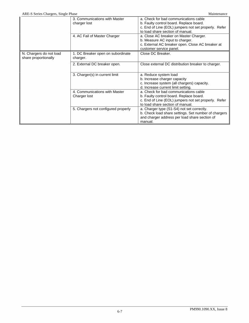
ARE-S Series Chargers, Single Phase Maintenance
PM990.1090.XX, Issue 8 6-7
3. Communications with Master charger lost
a. Check for bad communications cable b. Faulty control board. Replace board. c. End of Line (EOL) jumpers not set properly. Refer to load share section of manual.
4. AC Fail of Master Charger a. Close AC breaker on Master Charger. b. Measure AC input to charger. c. External AC breaker open. Close AC breaker at customer service panel.
N. Chargers do not load share proportionally
1. DC Breaker open on subordinate charger.
Close DC Breaker.
2. External DC breaker open. Close external DC distribution breaker to charger.
3. Charger(s) in current limit a. Reduce system load b. Increase charger capacity c. Increase system (all chargers) capacity. d. Increase current limit setting.
4. Communications with Master Charger lost
a. Check for bad communications cable b. Faulty control board. Replace board. c. End of Line (EOL) jumpers not set properly. Refer to load share section of manual.
5. Chargers not configured properly a. Charger type (S1-S4) not set correctly. b. Check load share settings. Set number of chargers and charger address per load share section of manual.
ARE-S Series Chargers, Single Phase Maintenance
PM990.1090.XX, Issue 8 6-8
6.3 CHECKING COMPONENTS This section describes methods that can be employed to determine whether a component has failed. A failed component must be replaced with a UNIPOWER approved part. See PN drawing(s) for parts list for component descriptions and UNIPOWER part numbers. CAUTION Do NOT perform internal maintenance on the charger when power is applied to the charger and/or the DC capacitors
ATTENTION Ne pas effectuer l’entretien à l’interne du chargeur lorsque la tension est appliquée au chargeur et / ou les condensateurs DC
Before performing any of the following tests: 1. Disconnect both the AC power and battery power by switching both circuit breakers off. It is
recommended that the AC be switched off at the user service panel in addition to switching of the AC breaker at the charger. Note that battery power will still be supplied to CB2, the DC circuit breaker, and to the Control and Display board and Interface board.
2. Using a voltmeter verify that the DC capacitors have been discharged. The capacitors will discharge automatically when the AC and DC breakers are open. Be sure that the capacitors have discharged before performing any maintenance.
Diodes - First, remove at least one connection to the diode, and then check using an analog ohmmeter to measure resistance, first cathode to anode and then anode to cathode. A good diode will show low resistance in one direction and a very high resistance the other direction. A shorted diode will show no or very low resistance both ways. An open diode will show a very high resistance both ways. Suggested scales for these checks are x10, x100, or the “diode check” meter function. Capacitors - First, isolate capacitors and then check with an ohmmeter. Proper scale range will vary as to type of meter and capacitor size. Start with highest range and work down. Reverse leads each time. If the capacitor is good, it will show a deflection towards zero resistance initially, then a steady increase toward infinite resistance. If, however, the capacitor is shorted, it will show zero resistance. If the capacitor is open, it will read infinite resistance. SCR modules- Remove the connections to the SCR module and check with a multimeter. A good SCR will indicate high resistance in both directions or an open diode check in both directions. A good diode will indicate closed in one direction and high resistance or open in the other. The gate to the cathode of the SCR should read good diode check. This test is not definitive and the only way to check for a good SCR module is to subject it to load current. Contact UNIPOWER Field Service for additional troubleshooting help.
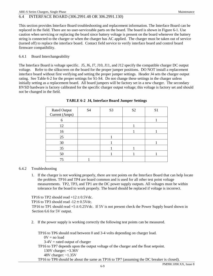
ARE-S Series Chargers, Single Phase Maintenance
PM990.1090.XX, Issue 8 6-9
6.4 INTERFACE BOARD (306.2991.48 OR 306.2991.130) This section provides Interface Board troubleshooting and replacement information. The Interface Board can be replaced in the field. There are no user-serviceable parts on the board. The board is shown in Figure 6-1. Use caution when servicing or replacing the board since battery voltage is present on the board whenever the battery string is connected to the charger or when the charger has AC applied. The charger must be taken out of service (turned off) to replace the interface board. Contact field service to verify interface board and control board firmware compatibility. 6.4.1 Board Interchangeability The Interface Board is voltage specific. J5, J6, J7, J10, J11, and J12 specify the compatible charger DC output voltage. Refer to the silkscreen on the board for the proper jumper positions. DO NOT install a replacement interface board without first verifying and setting the proper jumper settings. Header J4 sets the charger output rating. See Table 6-2 for the proper settings for S1-S4. Do not change these settings in the charger unless initially setting as a replacement board. All board jumpers will be factory set in a new charger. The secondary HVSD hardware is factory calibrated for the specific charger output voltage; this voltage is factory set and should not be changed in the field.
TABLE 6-2 J4, Interface Board Jumper Settings
Rated Output Current (Amps)
S4
S3 S2 S1
6 1 12 1 16 1 1 25 1 30 1 1 35 1 1 50 1 1 1 75 1
6.4.2 Troubleshooting
1. If the charger is not working properly, there are test points on the Interface Board that can help locate the problem. TP16 and TP4 are board common and is used for all other test point voltage measurements. TP2, TP3, and TP1 are the DC power supply outputs. All voltages must be within tolerance for the board to work properly. The board should be replaced if voltage is incorrect.
TP16 to TP2 should read +120.5Vdc. TP16 to TP3 should read -120.5Vdc. TP16 to TP1 should read +50.25Vdc. If 5V is not present check the Power Supply board shown in Section 6.6 for 5V output.
2. If the power supply is working correctly the following test points can be measured.
TP16 to TP6 should read between 0 and 3-4 volts depending on charger load.
0V = no load 3-4V = rated output of charger
TP16 to TP7 depends upon the output voltage of the charger and the float setpoint. 130V charger: ~3.36V 48V charger: ~1.35V
TP16 to TP8 should be about the same as TP16 to TP7 (assuming the DC breaker is closed).

ARE-S Series Chargers, Single Phase Maintenance
PM990.1090.XX, Issue 8 6-10
TP16 to TP9 should be about 0.6V for a 48V charger and 1.28V on a 130V charger if there is no ground short.
3. If the AC breaker is closed and AC voltage is present on the charger, there should be a 5V square wave of ~50% duty cycle between TP4 and TP12, and also between TP4 and TP13.
4. Check the settings of J4, J5, J6, J7, J10, J11, and J12. The charger should be powered off when changing these jumper settings.
6.4.3 Replacing the Interface Board Use caution when servicing or replacing the board since battery voltage is present on the board whenever the battery string is connected to the charger. The charger must be turned off to replace the interface board.
1. Refer to Chapter 4 Setup and Operation and turn off the charger. 2. Loosen the two quarter-turn captive fasteners and open the front panel. 3. At J14, J15, and J16 label each of the removable plugs with the alarm name printed on the circuit
board. Pull each plug up and out of its mating connector. 4. Disconnect the battery temperature sensor from terminal block J2, if present. 5. Disconnect the cabled connectors from the board. 6. Remove the screws securing the board and remove the board. Note the settings of J4, J5, J6, J7, J10,
J11, and J12. 7. On the replacement board, check the settings of J4, J5, J6, J7, J10, J11, and J12. See Table 6-2 for
proper settings. 8. Fasten the board to the charger using the screws removed above. Be sure to replace the wire at for the
ground detect switch at the bottom left screw. 9. Install the cabled connectors, alarm plugs, and battery temperature wiring. 10. Turn on the charger and test its operation and setup.
FIGURE 6-1 INTERFACE BOARD CONNECTIONS

ARE-S Series Chargers, Single Phase Maintenance
PM990.1090.XX, Issue 8 6-11
6.5 CONTROL AND DISPLAY BOARD (306.2993.00) Figure 6-2 shows the Control and Display Board. There are no user-serviceable parts on the board. Board substitution is recommended when troubleshooting. Contact field service for control board and interface board firmware compatibility.
FIGURE 6-2 CONTROL AND DISPLAY BOARD 6.5.1 Replacing the Board The Display/Control board can be replaced without the charger being turned off. The charger will continue to function at the last set-points received from the board.
1. Loosen the two quarter-turn captive fasteners and open the front panel. The board is located on the rear of the front panel.
2. Remove the communications cable at J1. The board should power down. Remove any other existing customer connections if applicable (load share, remote equalize, etc.)
3. Remove the screws securing the board and remove the board.
4. Fasten the board to the rear of the front panel using the screws removed above.
5. Reinstall any customer connections.
6. Reconnect the cable at J1.

ARE-S Series Chargers, Single Phase Maintenance
PM990.1090.XX, Issue 8 6-12
6.6 CONTROL POWER SUPPLY BOARD (306.2990.48 OR 306.2990.130) Figure 6-3 shows the Control Power Supply Board. There are no user-serviceable parts on the board. Board substitution is recommended when troubleshooting. The charger must be turned off when replacing this board. The power supply board is voltage specific. Be sure that the proper board model is being replaced based on the charger voltage rating. 48V charger – 306.2990.48, 48V Power Supply Board 130V charger – 306.2990.130, 130V Power Supply Board
FIGURE 6-3 CONTROL POWER SUPPLY BOARD
TP2 to TP1 should read +50.25Vdc. 120V AC voltage should be present at pins 1 and 3 of J2 when the AC breaker is closed.
6.6.1 Replacing the Board The charger must be turned off to replace the power supply board.
1. Be sure to turn off the AC and DC breakers.
2. Remove the cables at J1 and J2. Remove the cable at J3 using caution; if a battery is connected DC power will be present at J3.
3. Remove the screws securing the board and remove the board.
4. Fasten the new board to the panel using the screws removed above.
5. Reinstall cable connections.

ARE-S Series Chargers, Single Phase Maintenance
PM990.1090.XX, Issue 8 6-13
6.7 SCR TRIGGER BOARD (306.2989.00) Figure 6-4 shows the SCR Trigger Board. There are no user-serviceable parts on the board. Board substitution is recommended when troubleshooting. The charger must be turned off when replacing this board.
FIGURE 6-4 SCR TRIGGER BOARD 6.7.1 Replacing the Board The charger must be turned off to replace the SCR Trigger board.
1. Be sure to turn off the AC and DC breakers.
2. Remove the cables at J1 and J2.
3. Remove the screws securing the board and remove the board. Pay special attention to board orientation to facilitate replacing the board.
4. Fasten the new board to the panel using the screws removed above.
5. Reinstall cable connections.

ARE-S Series Chargers, Single Phase Maintenance
PM990.1090.XX, Issue 8 6-14
6.8 EXTENDED RELAY BOARD (306.2994.00) Figure 6-5 shows the Extended Relay board. There are no user-serviceable parts on the board. Board substitution is recommended when troubleshooting. Note: Alarms may occur when replacing this board.
FIGURE 6-5 EXTENDED RELAY BOARD 6.8.1 Replacing the Board The charger does not have to be turned off to replace the Extended Relay board.
1. Remove the cables at J11.
2. Remove any customer alarm connections at J1-J10. Be sure to label connections to facilitate reconnection on the new alarm board.
3. Remove the screws securing the board and remove the board.
4. Fasten the new board to the panel using the screws removed above.
5. Reinstall cable connection at J11.

ARE-S Series Chargers, Single Phase Options and Accessories
PM990.1090.XX, Issue 8 7-1
7. OPTIONS AND ACCESSORIES This chapter contains details about the options and accessories currently available for the charger. 7.1 LIGHTNING ARRESTER A surge suppression device connected across the AC service to ground prevents high energy transients from damaging the equipment.
FIGURE 7-1 LIGHTNING ARRESTER; 120, 208, 240 AND 480 VAC CONNECTIONS
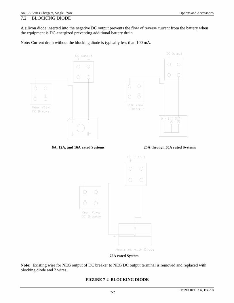
ARE-S Series Chargers, Single Phase Options and Accessories
PM990.1090.XX, Issue 8 7-2
7.2 BLOCKING DIODE A silicon diode inserted into the negative DC output prevents the flow of reverse current from the battery when the equipment is DC-energized preventing additional battery drain. Note: Current drain without the blocking diode is typically less than 100 mA.
6A, 12A, and 16A rated Systems 25A through 50A rated Systems
75A rated System
Note: Existing wire for NEG output of DC breaker to NEG DC output terminal is removed and replaced with blocking diode and 2 wires.
FIGURE 7-2 BLOCKING DIODE
ARE-S Series Chargers, Single Phase Options and Accessories
PM990.1090.XX, Issue 8 7-3
7.3 OUTPUT MOVS The output MOVs protect the charger from externally created voltage transients. The MOVs are connected from each output pole of the charger to the cabinet (earth). If an excessive transient enters the unit on the output cables, the MOVs clamp the voltage to an acceptable level. Repetitive clamping of transients and clamping high energy transients will degrade the MOVs requiring eventual replacement. 7.4 DRIP SHIELD The drip shield is intended to prevent water from dripping into the unit from the overhead structure indoors. When used, nothing should be set on the perforated top screen of the charger or the drip shield. Placing anything on the top screen may create a fire hazard. When the drip shield is used, personnel should avoid contact with the perforated top screen. 7.5 TEMPERATURE SENSOR The temperature sensor is connected to J2 on the interface board as shown in Figure 2-5 and described in 2.4.7. 7.6 GROUND DETECTION SWITCH (STANDARD) The Ground Detection Switch is that allows the operator to easily disable the ground detection by breaking the internal connection from the internal detection system and ground. Breaking the internal ground connection is useful for troubleshooting ground paths on the dc system or eliminating interactions with other ground detection equipment on the system. Unless other ground detection is in use on the dc system, the ground detection switch should be left in the ON position. 7.7 REMOTE COMMUNICATIONS Future expansion. This allows the charger to be controlled and monitored from a remote location over a 10/100Mbit ethernet network connection. 7.8 medium AND High interrupt AC breakers This option gives the charger an AC line current interrupting rating in excess of 10,000 Amps. 7.9 High interrupt dC breakers (standard on 48V systems) This option gives the charger a DC current interrupting rating in excess of 10,000 Amps.