Embed Size (px)
Citation preview

06
MA
SS
FL
OW
CO
NT
RO
LL
ER
S
0701
SO
LE
NO
ID V
ALV
ES
02
PR
OC
ES
S V
ALV
ES
03
PN
EU
MA
TIC
S
04
SE
NS
OR
S
05
MIC
RO
FL
UID
ICS
Solenoid Control ValvesProduct Overview

Bürkert | Solenoid Control Valves2 3Introduction
Bürkert has been hard at work on metering and controlling fluids for more
than 60 years. Anyone focussing so much on fluid substances for so long will
always also learn about their own attributes. Bürkert engineers are extremely
practical in interpreting their experiences with fluids, and in the development of
increasingly more efficient products, they work in accordance with the “what
flows, flows in” principle. So the results of internal research, market require-
ments, feedback and specific customer orders, for example, are all integrated.
30,000 products have now been developed, resulting in a powerful complete
catalogue. You will find a small portion of this impressive product range in
this Solenoid Control Valve brochure. We claim market leadership in this seg-
ment. But let’s turn towards the technology and applications of solenoid
control valves, often also called proportional valves.
Solenoid control valves are electromagnetic plunger valves which control flow
rates of liquids or gases. They open with certain stroke positions – dependent
on the valve control signal. Two forces counter one another in the valve: the
spring force and the force by a proportional solenoid. Without a power supply
the spring pushes the plunger directly on to the valve seat, which keeps the
valve outlet closed. But when power is supplied to the solenoid, the plunger
rises. The valve opens, and the fluid passes off.
You will find solenoid control valves in electronic devices in analytical or medical
technology, in burner controls, in cooling loops, in fuel dosing systems, in
fuel cell technology and in compact flow controllers. Everywhere these valves
convince others by reliability and accuracy.
With their simple, direct-acting design for closed control loops Bürkert solenoid
control valves are small, compact and cost-optimized. But even more: Our
latest generation of solenoid control valves impresses through precision, less
noise emission, sensitivity and long life.
In this catalogue we would like to present our products to you – products
together with their respective features, functionalities and areas of application.
On the other hand – please consider this brochure as a kind of snapshot
taken at the current status of solenoid valve technology, because Bürkert is
continuously on the move. After all, Bürkert will never stop measuring and
controlling everything that flows.
Technology of Solenoid Control Valves
Content3
4
6
10
15
22
25
29
30
Introduction
Fascination Bürkert
Product Overview
Valve Selection
Setup and Functioning of Solenoid Control Valves
Sizing of Valve Orifice
Typical Applications
System Engineering
Contacts at Bürkert

54 Fascination Bürkert
The brochure contains an over-view of Bürkert miniature valves and micro pumps, which allow for precise and safe handling of small volumes of liquids.
This brochure provides technical background information as well as a detailed product overview for the mass flow controller and meter product range.
This brochure presents our sole-noid control valves including their respective features, functions and typical applications.
Bürkert offers a remarkable range of servo-assisted and direct acting solenoid valves. Read more about them in this brochure.
Bürkert offers unlimited modularity for process control with angle-seat, globe and diaphragm valves in the widest range of configura-tions.
Here you can find our product range of pneumatic valves, valve units and automation systems as well as information on our control cabinet building.
Product Overview
0201
SO
LE
NO
ID V
ALV
ES
03
PN
EU
MA
TIC
S
04
SE
NS
OR
S
05
MIC
RO
FL
UID
ICS
06
MA
SS
FL
OW
CO
NT
RO
LL
ER
S
07
SO
LE
NO
ID C
ON
TR
OL
VA
LVE
S
Process and Control Valves
Welcome to the Fascinating World of Fluid Control Systems
Bürkert Product Program
Measurement and control: When it comes to working with liquids and gases, we are at your side – as a manufacturer of
sophisticated products, as a problem-solver with an eye for the big picture, and as a partner offering you reliable advice.
Since we started in 1946, we have developed into one of the world’s leading suppliers of Fluid Control Systems. At the
same time we have kept our status as a family-owned business with a foundation of strong basic values to highlight the
way we think and act.
We are one of the few suppliers on the market to cover the complete control loop. Our current product range
extends from solenoid valves through process and analytical valves to pneumatic actuators and sensors.
EXPERIENCE There are things which are not inherently yours. You have to gather them bit by bit. You receive them from others.
And you constantly have to acquire them anew. That is what makes them so valuable. Experience is one of those things.
For instance, because of our many years of experience with system solutions based on solenoid control valve tech-
nology, we can provide our extensive services to you – from consulting, development, and 3D CAD simulating to testing
and after-sales service. Whether individual product solutions or a pioneering new system for the entire control process:
Benefit from our experience!
COuRAgE Those who only work toward optimizing things that already exist will eventually reach the limits – technically, financially,
or personally. In order to overcome these limits, courage is needed: the courage to be different and trust one’s own
ideas; the courage to venture into the unknown, searching for new ways to develop products that have never existed
before. We have this courage. By pooling and utilizing our competencies across all sectors, you benefit from our
cumulative knowledge in controlling gases and liquids.
ClOSENESS There are things we simply take for granted. Only when they are gone, do we realize how important these things really
were. This applies in particular to closeness. Without closeness, it is very difficult to build relationships and a good
understanding of one another. As an established medium-sized company, we know that. And that is why we are always
there for you. Working with you, we develop the best possible solutions for your projects in the area where gases or
liquids have to be controlled. Our global presence in 35 locations enables us to press ahead with technical innovations
for our customers around the world.
Here you can find our sensors, transmitters and controllers for measuring and controlling flow, temperature, pressure, level, pH/ORP and conductivity.
0401
SO
LE
NO
ID V
ALV
ES
02
PR
OC
ES
S V
ALV
ES
03
PN
EU
MA
TIC
S
05
MIC
RO
FL
UID
ICS
06
MA
SS
FL
OW
CO
NT
RO
LL
ER
S
07
SO
LE
NO
ID C
ON
TR
OL
VA
LVE
S
Sensors, Transmitters and ControllersProduct Overview
7Bürkert | Solenoid Control Valves6
Type 2871 2873 2875 2836 6024 6223 ²)
Operating principle Plunger directly on valve seat (NC)
Plunger directly on valve seat (NC)
Plunger directly on valve seat (NC)
Plunger directly on valve seat (NC)
Plunger directly on valve seat (NC)
Plunger directly on servo piston (NC)
Design feature Frictionless plunger guide Frictionless plunger guide Frictionless plunger guide Slide ring Slide ring Servo-assisted
Width of solenoid 20 mm 32 mm 49 mm 72 mm 49 mm 32-43 mm
Power consumption
2-5 W(depending on application)
9 W 16 W 24 W 18 W 8-15 W
Orifice sizes 1) 0.05-2 mm 0.8-4 mm 2-8 mm 3-12 mm 8-12 mm 10-20 mm
Repeatability 0.25 % of F. S. 0.5 % of F. S. 0.5 % of F. S. 1 % of F. S. 0.5 % of F. S. 1 % of F. S.
Sensitivity 0.1-0.025 % of F. S. 0.25 % of F. S. 0.25 % of F. S. 0.5 % of F. S. 0.5 % of F. S. 1 % of F. S.
Span 0.5-100 % 0.5-100 % 0.5-100 % 4-100 % 4-100 % 10-100 %
Response time <15 ms <20 ms <25 ms <100 ms <50 ms <200 ms
Valve material Brass, stainless steel Brass, stainless steel Brass, stainless steel Brass, stainless steel Brass, stainless steel Brass, stainless steel
Sealing material (typ.) FKM, EPDM FKM, EPDM FKM, EPDM FKM, EPDM FKM FKM
Port connection 1/8", sub-base 1/8", 1/4", sub-base 3/8", 1/2", sub-base 1/2", 3/4" 1/2", 3/4" 3/8", 1/2", 3/4", 1"
Typical application – Medical and analytical equipment
– Burner controls– Fuel cell technology– Plasma control– Powder coating
– Burner controls– Waste gas treatment– Inert gas dosing– Plasma control– Vacuum control– Fuel dosing
– Fuel cell technology– Test stand technology– Burner controls– Vacuum control– Filling level control
– Cooling– Inert gas dosing
– Combustion gas dosing – Forced air throttling
– Cooling/heating circuits– Water dosing
Product Overview
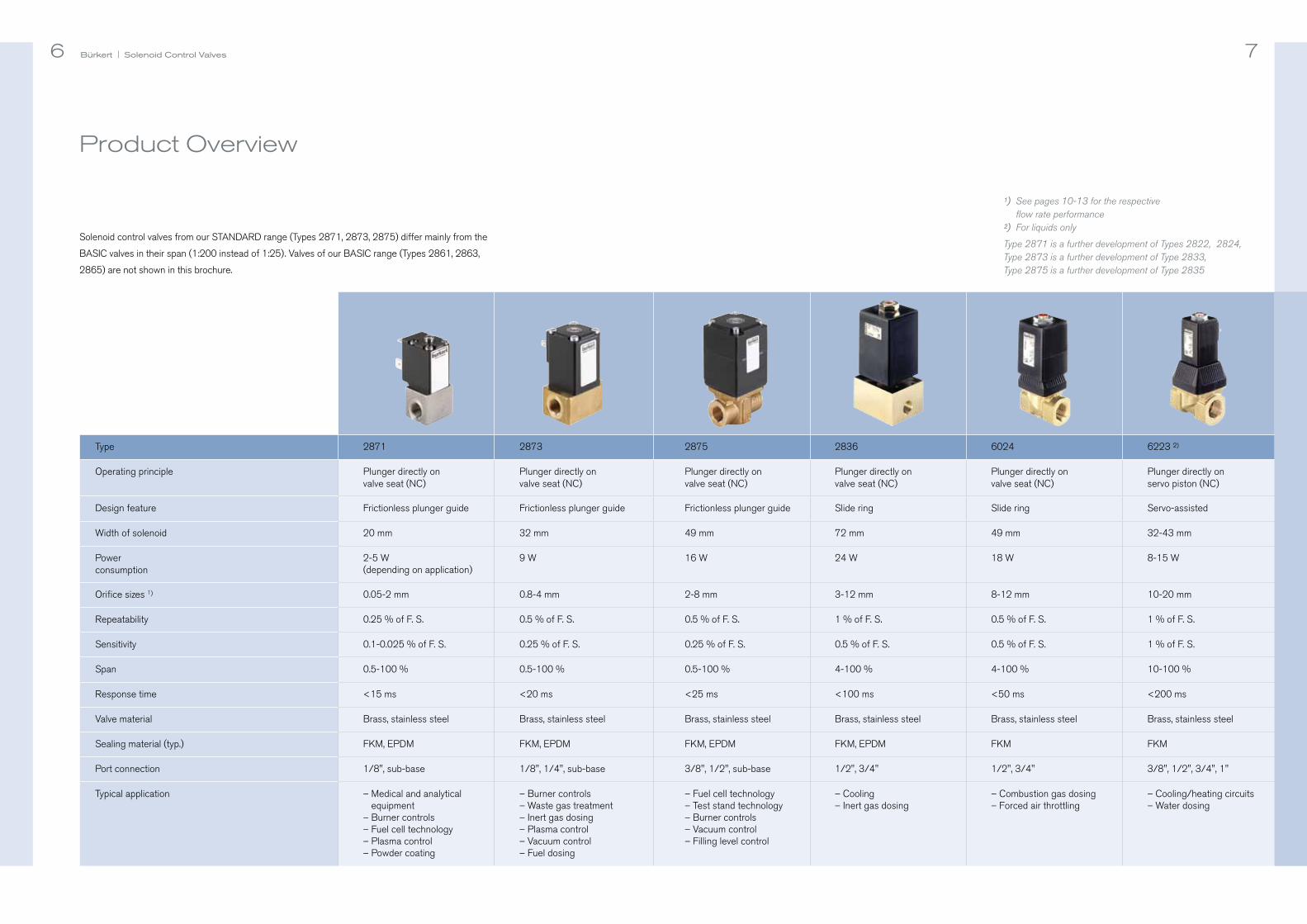
¹) See pages 10-13 for the respective flow rate performance
²) For liquids only
Type 2871 is a further development of Types 2822, 2824,Type 2873 is a further development of Type 2833, Type 2875 is a further development of Type 2835
Solenoid control valves from our STANDARD range (Types 2871, 2873, 2875) differ mainly from the
BASIC valves in their span (1:200 instead of 1:25). Valves of our BASIC range (Types 2861, 2863,
2865) are not shown in this brochure.

9Bürkert | Solenoid Control Valves8 Product Overview
Type 8605 8611
Function Digital PWM control Digital PI controller,
two-position controller
Versions Rail or valve mounting Fitting, wall, rail, cabinet or valve mounting
Signals – Set point (0-5 V, 0-10 V, 0-20 mA, 4-20 mA)
– PWM output (80 Hz-6 kHz)
– Set point (0-10V or 4-20mA)– Actual process value (4-20mA)– Sensor input (4-20mA, Pt100 or frequency) e. g., pressure, temperature or flow– Control output signal
(4-20mA or PWM)– Binary input– Binary output
Operating voltage 12, 24 VDC 24 VDC
Max. power consumption 1 W (without valve) 2 W (without valve)
Valve outlet Max. 2 A (PWM) Max. 2 A (PWM)
Software functions – Valve setting (frequency, min./max. opening)
– Zero point cut-off – Temperature compensation – Ramp function – Down-/upload of parameterization
– Controller setting– Valve setting (all Bürkert solenoid control valves stored)– Sensor setting (all Bürkert flow sensors stored)– Configuration of switching (binary)
signals– Scaling of set point and process value
signals– Valve and sensor setting– Code protection– etc.
Control Electronics for Solenoid Control Valves
Feature Benefits
Simple, compact and direct-acting, without position feedback
Cost-effective design, Very fast reaction
Guiding of plunger with flat spring Extremely good repeatability resulting in reliable setting of processes again and again,Very good sensitivity, high span
Epoxy resin moulded coil,tight encapsulation of the valve system
High protection class (IP 65),safety
PWM control Lower hysteresis,Static friction prevented,Very good response sensitivity
Seat seal integrated in the plunger Close tight function, no additional shut-off valve required
Precise and Repeatable Results with Solenoid Control Valves

Bürkert | Solenoid Control Valves 1110
Valve Selection
kVs [m³/h]/ cV [US Gal/min] 1) DN Max. operating pressure [bar/psi] Type
[mm] 00.2 /2.9
0.4 /5.8
0.57.2
0.7 /10.1
1 /14.5
1.5 / 21.7
2 /29.0
3 /43.5
3.5 /50.7
4 /58.0
5 /72.5
6 /87.0
8 /116.0
10 /145.0
12 /174.0
16 /232.0
25 /362.6
0.00006 / 0.00007 0.05
2871
0.00025 / 0.00029 0.1
0.0010 / 0.0011 0.2
0.0020 / 0.0023 0.3
0.0040 / 0.0046 0.4
0.010 / 0.011 0.6
0.018 / 0.021 0.8
0.027 / 0.031 1.0
0.038 / 0.044 1.2
0.055 / 0.064 1.6
0.090 / 0.105 2.0
kVs [m³/h]/ cV [US Gal/min] 1) DN Max. operating pressure [bar/psi] Type
[mm] 00.2 /2.9
0.4 /5.8
0.57.2
0.7 /10.1
1 /14.5
1.5 / 21.7
2 /29.0
3 /43.5
3.5 /50.7
4 /58.0
5 /72.5
6 /87.0
8 /116.0
10 /145.0
12 /174.0
16 /232.0
25 /362.6
0.018 / 0.021 0.8
0.04 / 0.047 1.2
0.06 / 0.07 1.5
0.10 / 0.12 2.0 2873
0.15 / 0.18 2.5
0.22 / 0.26 3.0
0.32 / 0.37 4.0
0.12 / 0.14 2.0
0.25 / 0.29 3.0
0.45 / 0.52 4.0 2875
0.80 / 0.93 6.0
1.10 / 1.28 8.0
¹) For an explanation of kVs/cV value and sizing please see page 22

Bürkert | Solenoid Control Valves 1312
Note:- All valves for medium temperatures of -10 to +90 °C- Typical power supply 24V DC- All valves offer protection class IP 65Generally valid:The bigger the valve orifice, the lower the maximum possible operating pressure at which the valve closes tight
Valve Selection
kVs [m³/h]/ cV [US Gal/min] 1) DN Max. operating pressure [bar/psi] Type
[mm] 00.2 /2.9
0.4 /5.8
0.57.2
0.7 /10.1
1 /14.5
1.5 / 21.7
2 /29.0
3 /43.5
3.5 /50.7
4 /58.0
5 /72.5
6 /87.0
8 /116.0
10 /145.0
12 /174.0
16 /232.0
25 /362.6
0.25 / 0.29 3.0
0.40 / 0.46 4.0
0.90 / 1.05 6.02836
1.5 / 1.7 8.0
2.0 / 2.3 10.0
2.5 / 2.9 12.0
1.4 / 1.6 8.0
2.0 / 2.3 10.0
2.8 / 3.2 12.06024
1.4 / 1.6 10.0 2)
2.5 / 2.9 13.0 2)
5 / 5.8 20.0 2)
6223
¹) For an explanation of kVs/cV value and sizing please see page 22
²) Max. differential pressure allowed: 3 bar

Bürkert | Solenoid Control Valves14 15
Fig. 1: Schematic diagram of a closed control loop
Flow sensor
Control valve signalSet point
setting
Pipe inlet Pipe outlet
Solenoid control valve
Actual value x Control electronics
xout
Actual value feedback
xd = w-x
wy
14 Aufbau und Funktion eines Solenoid control-Magnetventils
Setup and Functioning of Solenoid Control Valves
Control valve, control armature, metering valve: the terms might be different – but it is the same
product that they actually mean. In process-related practical use these components are usually
called control valves, and the name refers to their function. They control and regulate the rate
of flowing media (fluids). Control valves are operated in different ways: pneumatically, electro-
motorized, piezo-electrically and electro-magnetically.
The various drive principles essentially differ in price, size, type of media separation, dynamics and
force properties.
Electro-magnetically activated control valves are called "solenoid control valves" or "proportional
valves", which cover the orifice range below 12 mm (direct-acting valves) and 8-25 mm (servo-
assisted valves). Solenoid control valves are used as metering valves in closed control loops.
The valve eliminates the difference here between the reference and actual value of the mapped
process value (see fig. 1). However solenoid control valves – depending on valve type and applica-
tion – are also used in open control loops in which the valve is operated without any feedback of
the actual process value.

Bürkert | Solenoid Control Valves Setup and Functioning of Solenoid Control Valves 1716
Solenoid shut-off valves are the basis for Bürkert solenoid control valves. Without electrical power
the spring forces the plunger directly on the valve seat. With that the valve is closed. Electrical current
through the solenoid (coil) causes a magnetism which lifts the plunger against the spring force.
The valve opens. With constructive changes in the solenoid shut-off valves, a balance between spring
and magnetic force can be produced for any coil current. The intensity of the coil current or the
magnetic power influences both the stroke of the plunger and the valve’s opening degree, whereby
valve opening (flow rate) and coil current (control signal) are ideally linear dependent on one
another (see fig. 2).
The flow direction in direct-acting solenoid control valves is typically from below seat. The medium
flowing in from below presses together with the generated magnetic force against the tension force
of the return spring, pressing from above. For this reason alone it makes sense to set the minimum
and maximum flow rate value of the working range (coil current) under operating conditions. Bürkert
solenoid control valves are closed without electrical power (NC, normally closed).
With an even geometry of the plunger and the plunger counterpart/stopper (flat stopper geometry) the
magnetic force drops too much with rising air gap making it impossible to use the valve as a control
valve. Equal balance states between spring and magnetic force at different values of the electrical
current can only be achieved with a specific design of both components. With the design of a conically
shaped area on the outside part of the stopper and a virtually mirror-inverted slant in the top part of
the plunger (see conical stopper geometry in fig. 3).
In the power off state the spring force alone closes the valve. A seal integrated in the bottom of the
plunger ensures that the fluid does not leak through the closed valve.
The plunger is guided precisely through the valve unit by a guide pin (top) and a flat spring (bottom).
The more flexibly the plunger slides through the coil, the more pronounced the response sensitivity
and the more reproducible the control positions. This is because, in addition to the magnetic force
and spring force, a third unavoidable force, unwanted because of its consequences, enters the pic-
ture: friction force. Friction disturbs the adjustment characteristic. It can, however, be significantly
reduced with a precise guiding of the plunger and special electronic controlling.
Fig. 3: Comparison flat stopper design – conical stopper design
Closed state Controlled inclined position Opened stateFlat stopper geometry(shut-off valve)
Conical stopper geometry(solenoid control valve)
Fig. 2: Functional principle of direct-acting solenoid control valves
left: Characteristic of an electromagnetic shut-off valve
right: Characteristic of an electromagnetic control valve
Control signal Control signal
Flow
rate
Flow
rate
Conical stopper
Flat stopper
Plunger counterpart/stopper
Plunger

Bürkert | Solenoid Control Valves Setup and Functioning of Solenoid Control Valves 1918
In principle it is possible to control the proportional magnet with variable DC voltage, but static friction
can appear here on the plunger’s guide points. This impairs the sensitivity of the valve, and results
in greater hysteresis effects. To prevent static friction, the normal inlet signal is converted with a special
control electronics – usually into a pulse width modulated voltage signal (PWM controlling, see
fig. 4). This kind of control puts the plunger into a very fast but weak amplitude oscillation. Despite, or
moreover because of the oscillation, the plunger’s balanced state is maintained, as is its constant
sliding friction. And the plunger’s oscillation motion has absolutely no effect on the fluid’s flow be-
haviour.
With PWM control the effective coil current with constant voltage supply is set via the duty cycle of
the rectangular signal. The PWM frequency is harmonized here on the one hand with its resonance
frequency and the damping of the spring-plunger-system, and on the other hand with the magnetic
circuit’s inductance. If the duty cycle t1/T (t1: power-on time, T: cycle duration, f=1/T: frequency) in-
creases, the effective coil current “I” also increases, because the rectangular signal has also increased.
If, however, the duty cycle falls, the effective coil current also falls.
Generally speaking: Small coils (e. g., type 2871) with low magnetic force react sensitively to high-
er frequencies. With low frequencies these generate high motion amplitudes and an unnecessarily
high noise level. Big coils with a high magnetic force (e. g., type 2875), however, only result in dither
movements, and therefore sliding friction with low frequencies.
Controlling Solenoid Control Valves
U
24V
Pulse width variation results in different coil currents
t1 Tt
Fig. 4: PWM control signal
Typical Functions of the Control Electronics
Current control for coil heating compensation
Coil heating changes the temporary effective electrical resistance. It is therefore beneficial to control
the coil current electronically. Current control is especially important in open control loops, whereby it is
irrelevant in closed process control loops.
Adjusting the minimum and maximum coil current to
application-specific pressure conditions
The current values must be set under operating conditions – when the valve begins to open, and
when the valve is fully opened. The working range of the respective valve types depends on their
orifice and the respective pressure conditions in the system (primary pressure and back pressure).
For all direct-acting solenoid control valves that are inflowed under the seat, the current value for
the opening start falls with increasing inlet pressure. With an increasing pressure drop via the valve,
the current value at which maximum flow rate is reached falls.
Zero point shut-off for closing the valve tight
Zero point shut-off can be set up to a value of 5 % of the maximum inlet signal. This guarantees
that the valve is closed tight. With inlet signals that are lower than originally set, the coil current is
immediately set to zero. This then closes the valve. If no zero point shut-off is specified, the valve
is controlled with the lowest duty cycle, even with 0 % set point given.
Ramp function
Set point changes (with rising or falling flank) can be set with an effective delay of up to 10 sec-
onds. This balances the effects of volatile set point changes, which can cause fluctuations in some
systems.
Average coil current
Effective coil current (I)

Bürkert | Proportionalventile16 2120 Solenoid control Parameters
kVs value/QNn value
Fluidic valve comparisons can be made via the kVs value (m³/h unit). This value is measured at
water’s flow rate at 20 °C and 1 bar relative pressure at the valve inlet, compared with 0 bar at the
valve outlet. A second flow rate value is often given for gases. This is the QNn value. The QNn value
provides the nominal flow rate value in lN/min air (20 °C) at 6 barg at the valve inlet and 1 bar pres-
sure loss via the valve. Standard conditions for the gas are 1013.25 mbar absolute and a tempera-
ture of 273.15 K (0 °C).
Hysteresis
The highest fluidic output signal difference with an upward and downward run through of the full
electric input signal range; given in % of the maximum fluidic output signal. Hysteresis is a result of
friction and magnetism.
Sensitivity
The lowest set point difference that results in a measurable change in the fluidic output signal;
given in % of the maximum fluidic output signal.
Linearity
Dimension for maximum deviation from the linear (ideal) characteristics; given in % of the maximum
fluidic output signal.
Repeatability
Range in which the fluidic output value disperses when the same electric input signal coming
from the same direction is repeatedly set; given in % of the maximum output signal.
Turn-down ratio (span)
Ratio of the kVs value ratio to the lowest kV, at which the height and incline of the characteristics
remains within a tolerance range in the ideal characteristic curve.
In applications in practice the correct configuration of the valve is a prerequisite for proper
functioning (see “Sizing of Valve Orifice”).
Characteristic Data of Solenoid Control Valves

Bürkert | Solenoid Control Valves 2322
use as Control Valve: Sizing of Valve Orifice
For correct and accurate control functioning, solenoid control valves must be configured and
selected according to their special purpose. The most important parameters for selecting a solenoid
control valve are, on one hand, the kV value (given in cubic meters per hour) and, on the other hand,
the application’s pressure range. The lower the valve’s orifice or the stronger the coil, the higher the
pressure the valve can shut-off. The highest kV value needed is calculated on the basis of the
following parameters: Valve inlet pressure, valve outlet pressure, the fluid’s density, maximum flow rate
required, and the fluid’s temperature. With the sizing formulas (see one of Bürkert’s data sheets
for solenoid control valves), supercritical or subcritical flow and aggregate states (gaseous, liquid or
vaporous) are distinguished.
On the basis of the calculated kV value and the pressure range of the planned application, a corres-
pondingly appropriate valve type and its required orifice can now be determined. The spreadsheets
with the valve performance data on pages 10 to 13 of this brochure will help you to find the right
valve type for this. Please observe: The application’s kV value must be lower than the valve’s kVs value
that is reached at maximum opening.
You will find more information on the kVs value on page 21.
Some countries use the cV value instead of the kVs value. This flow rate is given in US gallons per
minute (1 GPM = 0.227 m3/h) and determined with water at 60° Fahrenheit and a pressure differ-
ence via the valve of 1 psi (equal to 0.069 bar). The conversion factor between kV and cV is 0.857
(kV is smaller than cV).
The correct configuration (determining the valve’s orifice) is extremely important for the solenoid
control valve’s correct functioning. With a high orifice setting the valve can already reach full flow
rate at a very small opening (stroke). The remaining stroke then is useless, which, more to the point,
impairs resolution and the general control quality of the valve. With an orifice size that is too small
on the other hand, the valve won’t reach full flow rate. In the interests of the system’s acceptable
flow characteristics, the valve authority should not be below 0.3. That means that 30 % of the system’s
pressure should be available to drop over the control valve.
Bürkert provides a calculation tool for the correct control valve sizing: the Easy Valve Sizer, which
makes finding the optimum valve orifice so easy.
1. What medium (fluid) do you want to control?
With regard to its chemical-physical reaction behaviour, it must be checked whether the valve parts
in contact with the medium are compatible with the medium itself.
2. How high is the maximum operating pressure?
The valve must be able to shut off the highest pressure in the application.
3. What are the process data?
For optimal sizing of the valve orifice there are some issues to be cleared up. At first there is the
scope of the required maximum flow rate, Qnom, which typically has to be controlled. The valve’s
maximum flow rate can, however, actually be higher, and the figures of the pressure values at Qnom
must be measured immediately before and after the valve (p1, p2). These values are often not iden-
tical to the inlet and outlet pressure of the overall system, because additional flow resistances have
an effect both before and after the valve (pipes, shut-off valves, nozzles, etc.). If the inlet (p1) and
outlet pressure (p2) cannot be determined, both must be estimated taking all pressure drops into
account. Information on the medium temperature (T1) and the standard density (pN) of the medium
at 273 Kelvin (0 °C) and 1013 mbar (1 bar) also helps in calculating the valve orifice. Whether or
not the minimum flow rate can be adjusted (Qmin) is checked using the achievable turn-down ratio
of the valve considered.
Here is a brief summary of the sizing criteria once again:
– The valve’s kVs is greater than the application’s kV; ideally by approx. 10 %
– The pressure that can be withstood by the valve is greater than the max. operating pressure
before the valve
Brief Instructions – How do I Find the Right Solenoid Control Valve?

Bürkert | Proportionalventile20 25
level Control with Pressurization(Flow Pressure Control)
Set point setting
Nitrogen
Solenoid control valve Pressure value of the
container atmosphere
p
PID
Actuator Control (Static Pressure Control)
Two solenoid control valves control
the air for pneumatic drive (piston
valve, cylinder, etc.). The PID con-
troller determines which of the two
valves must open. The control elec-
tronics set the drive via the solenoid
control valves so that the process
value corresponds with the set point
given.
Atmospheric pressure control is one
possible type of level control. Via two
solenoid control valves, a PID con-
troller supplies enough air or nitrogen
here so that there is always the same
pressure pressing against the fluid
that changes when the fluid pressure
drops through removing a portion of
the fluid.
Measurement Control valve with pneumatic drive
Control electronics
Control electronics
Set point setting
Pipe inlet Pipe outlet
Feedback of process value Venting out
Venting in
Out
Solenoid control valvePID
Typical Applications

Bürkert | Solenoid Control Valves Typical Applications 2726
Burner / Flame Control
Ejectors / Pressure Control
Measurement
Process value feedback
Mixing nozzle
Solenoid control valve
Outlet
Process value feedback
Combustion gas
Set point setting
Oxidant gas
Burner controller
Check valve
PID
Measurement
Control electronics
Set point setting
Propellant gas inlet
Solenoid control valve
Ejectors
Suction side
PID
MeasurementVacuum pressure
Ejectors
Outlet
Outlet
Propellant gas in
Control electronics
Vacuum side
Set point setting
Solenoid control valve
PID
As before, the suction power is
controlled by the solenoid control
valve. In this case the inlet pressure
on the propellant side is kept con-
stant at a reference value.
Two gases must be controlled in a burner
control system; both are in a desired
ratio with one another. The ratio of com-
bustion gas to oxidant gas, e. g., air or
oxygen, is determined by the flame that
is required for the respective process.
The solenoid control valve controls
the propellant gas flow rate. More
propellant gas creates greater suc-
tion power and a deeper vacuum in
the suction line. The controller sets
the valve according to the vacuum
pressure.
Flow Control
Measurement
Solenoid control valve
PID
Flow controller
Pipe inlet Pipe outlet
Process value feedback Flow rate
A solenoid control valve can be used
directly as a control valve, for direct
flow control, for example.
p
p
Set point setting

Bürkert | Solenoid Control Valves 2928
System Engineering
System for controlling cooling water
with reference to the temperature
of the process water
Compact, space-optimized so-
lenoid control valve system with
plastic moulded base
Five channel gas controller,
featuring one common electronic
board only
Fieldbus controlled, three channel
pressure controller
System for controlling cooling water
into different transmission lines
Mixture ofCold and Warm Water
Temperature Control
Mixed water
Process side
MeasurementTemperature Pt100
Solenoid control valve
Solenoid control valve
Heat exchanger
Cold water
Temperature controller
Temperature controller
Warm water
Cold water
Warm water
PID
PID
T
MeasurementTemperature Pt100
A Pt100 temperature sensor measures
the temperature of the mixed water.
The temperature controller brings this
temperature to the given reference
value by controlling the two solenoid
control valves accordingly.
The solenoid control valve sets the
cold water supply to the heat ex-
changer in accordance with the meas-
ured process water temperature. If
this is higher than the reference value,
more cold water (cooling water) is
required. If it is lower than the reference
value, less cooling is required. A
heating circuit works in a similar way.
T
A global network of Bürkert system engineering facilities and long-standing years of experience
in the systems business allow us to develop and quickly implement tailor-made solutions for your
requirements. Engineers and scientists from the most diverse specialist fields are at your disposal
for competent and expert consulting. Our range of customized solutions is highly diversified and
ranges from connection plates, plastic injection components, the integration of additional compo-
nents, electronics, software and connections via special interfaces, right through to the use of cus-
tomized bus technology.
We can therefore ensure that you get the perfect product for your application. The focus of our
work is both on the optimization of procurement and installation costs, and a higher level of inte-
grating functions into the system. Furthermore, with its geometric dimensions and the mechanical
and electrical interfaces we put in place, the system is optimized to fit into its later application
environment.
Solenoid control valve

30
Bürkert – Close to You
Bürkert | Solenoid Control Valves
Austria
Belgium
Czech Republic
Denmark
Finland
France
Germany
Italy
Netherlands
Norway
Poland
Portugal
Spain
Sweden
Switzerland
Turkey
United Kingdom
China
Hong Kong
India
Japan
Korea
Malaysia
Philippines
Singapore
Taiwan
South Africa
Russia
United
Arab
EmiratesArgentina
Brazil
Canada
USA
Australia
New Zealand
For up-to-date addresses
please visit us at
www.burkert.com.
Credits: © and concept: Christian Bürkert GmbH & Co. KG | Realization: WOLF, Berlin | Photography: Münch Lichtbildnerei, Stuttgart; Studio Flamisch,
Düsseldorf | 3D-Drawings: 3D Sales Technologies GmbH. All people shown are employees at Bürkert. Thank you for your support (and spirit).

89
44
62
Ve
rsio
n 1
2/2
01
3
Prin
t on
lyP
DF
Upd
ate
ww
w.w
olf-
corp
orat
e.de
Bürkert Fluid Control SystemsChristian-Bürkert-Straße 13-1774653 IngelfingenGermany
Tel. +49 (0) 7940/10-0Fax +49 (0) 7940/10-91 204