Embed Size (px)
Citation preview

JESS-LINK PRODUCTS CO., LTD
PRODUCT SPECIFICATION PAGE 1/15
TITLE
PCI-e OCuLink Connector
DOC No. DSPC-001534
REVISION:
08
AUTHORIZED BY:
James
DATE:
12/14/2017
CLASSIFICATION:
UNRESTRICTED
OCuLink x4 Cable end
OCuLink x4 Receptacle Connector

JESS-LINK PRODUCTS CO., LTD
PRODUCT SPECIFICATION PAGE 2/15
TITLE
PCI-e OCuLink Connector
DOC No. DSPC-001534
REVISION:
08
AUTHORIZED BY:
James
DATE:
12/14/2017
CLASSIFICATION:
UNRESTRICTED
1.0 SCOPE
This Product Specification covers the performance requirements of the Pitch 0.5mm PCI-e OCuLink
Pluggable Connectors
2.0 PRODUCT DESCRIPTION
2.1 PRODUCT NAME AND SERIES NUMBER(S)
● PCI-e OCuLink x4 Receptacle R/A SMT with SMT shell Attached
JPC DWG No.: SD_P933G042-D
● PCI-e OCuLink x4 Receptacle R/A SMT with DIP shell Attached
JPC DWG No.: SD_P933F042-D
● PCI-e OCuLink x4 Receptacle VT SMT with SMT shell Attached
JPC DWG No.: SD_P931G042-D
● PCI-e OCuLink x4 Receptacle VT SMT with DIP shell Attached
JPC DWG No.: SD_P931F042-D
● PCI-e OCuLink x4 Receptacle VT SMT with HR-I DIP shell Attached
JPC DWG No.: SD_P931C042-D
● PCI-e OCuLink x4 Receptacle VT SMT with HR-II DIP shell Attached
JPC DWG No.: SD_P931D042-D
● PCI-e OCuLink x4 Receptacle VT SMT with HR-III DIP shell Attached
JPC DWG No.: SD_P931E042-D
● PCI-e OCuLink x8 Receptacle R/A SMT with SMT shell Attached
JPC DWG No.: SD_P933G080-D
● PCI-e OCuLink x8 Receptacle R/A SMT with DIP shell Attached
JPC DWG No.: SD_P933F080-D
● PCI-e OCuLink x8 Receptacle VT SMT with SMT shell Attached
JPC DWG No.: SD_P931G080-D
● PCI-e OCuLink x8 Receptacle VT SMT with DIP shell Attached
JPC DWG No.: SD_P931F080-D
● PCI-e OCuLink x8 Receptacle VT SMT with HR-II DIP shell Attached
JPC DWG No.: SD_P931D080-D

JESS-LINK PRODUCTS CO., LTD
PRODUCT SPECIFICATION PAGE 3/15
TITLE
PCI-e OCuLink Connector
DOC No. DSPC-001534
REVISION:
08
AUTHORIZED BY:
James
DATE:
12/14/2017
CLASSIFICATION:
UNRESTRICTED
● PCI-e OCuLink x4 cable Straight type and Active Latch
JPC DWG No.: Refer to Cable drawing
● PCI-e OCuLink x4 cable Right Angel type and Active Latch
JPC DWG No.: Refer to Cable drawing
● PCI-e OCuLink x4 cable Left Side type and Active Latch
JPC DWG No.: Refer to Cable drawing
● PCI-e OCuLink x4 cable Straight type and Passive Latch
JPC DWG No.: Refer to Cable drawing
● PCI-e OCuLink x8 cable Straight type and Active Latch
JPC DWG No.: Refer to Cable drawing
● PCI-e OCuLink x8 cable Right Angel type and Active Latch
JPC DWG No.: Refer to Cable drawing
2.2 DIMENSIONS,MATERIS,PLATINGS AND MARKING
See Customer Drawing for information on dimensions, material, plating and marking
JESS-LINK PRODUCTS CO., LTD
PRODUCT SPECIFICATION PAGE 4/15
TITLE
PCI-e OCuLink Connector
DOC No. DSPC-001534
REVISION:
08
AUTHORIZED BY:
James
DATE:
12/14/2017
CLASSIFICATION:
UNRESTRICTED
3.0 APPLICABLE DOCUMENTS AND SPECIFICATIONS
PCIe OCuLink Specification
EIA 364 Series: Electrical Connector Test Procedures Including Environmental Classifications with
Test Procedures
EIA 364-1000 Environmental Test Methodology for Assessing the Performance of
Connectors and Sockets Used in Business Office Applications
4.0 QUALIFICATION
Laboratory condition and sample selection are in accordance with EIA 364
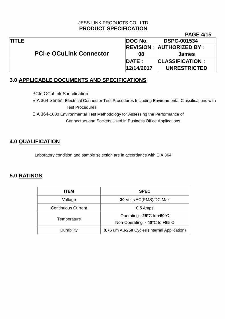
5.0 RATINGS
ITEM SPEC
Voltage 30 Volts AC(RMS)/DC Max
Continuous Current 0.5 Amps
Temperature Operating: -25°C to +60°C
Non-Operating: - 40°C to +85°C
Durability 0.76 um Au-250 Cycles (Internal Application)
JESS-LINK PRODUCTS CO., LTD
PRODUCT SPECIFICATION PAGE 5/15
TITLE
PCI-e OCuLink Connector
DOC No. DSPC-001534
REVISION:
08
AUTHORIZED BY:
James
DATE:
12/14/2017
CLASSIFICATION:
UNRESTRICTED
6.0 PERFORMANCE
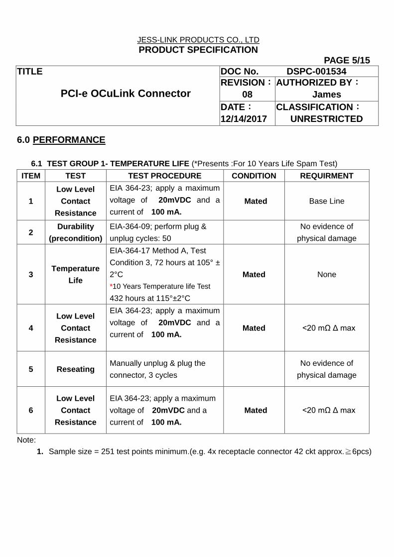
6.1 TEST GROUP 1- TEMPERATURE LIFE (*Presents :For 10 Years Life Spam Test)
ITEM TEST TEST PROCEDURE CONDITION REQUIRMENT
1
Low Level
Contact
Resistance
EIA 364-23; apply a maximum
voltage of 20mVDC and a
current of 100 mA.
Mated Base Line
2 Durability
(precondition)
EIA-364-09; perform plug &
unplug cycles: 50
No evidence of
physical damage
3 Temperature
Life
EIA-364-17 Method A, Test
Condition 3, 72 hours at 105° ±
2°C
*10 Years Temperature life Test
432 hours at 115°±2°C
Mated None
4
Low Level
Contact
Resistance
EIA 364-23; apply a maximum
voltage of 20mVDC and a
current of 100 mA. Mated <20 mΩ Δ max
5 Reseating Manually unplug & plug the
connector, 3 cycles
No evidence of
physical damage
6
Low Level
Contact
Resistance
EIA 364-23; apply a maximum
voltage of 20mVDC and a
current of 100 mA.
Mated <20 mΩ Δ max
Note:
1. Sample size = 251 test points minimum.(e.g. 4x receptacle connector 42 ckt approx.≧6pcs)

JESS-LINK PRODUCTS CO., LTD
PRODUCT SPECIFICATION PAGE 6/15
TITLE
PCI-e OCuLink Connector
DOC No. DSPC-001534
REVISION:
08
AUTHORIZED BY:
James
DATE:
12/14/2017
CLASSIFICATION:
UNRESTRICTED
6.2 TEST GROUP 2 -CYCLIC TEMPERATURE & HUMIDITY
ITEM TEST TEST PROCEDURE CONDITION REQUIRMENT
1
Low Level
Contact
Resistance
EIA 364-23; apply a maximum
voltage of 20mVDC and a
current of 100 mA.
Mated Base Line
2 Durability
(precondition)
EIA-364-09; perform plug &
unplug cycles: 50
No evidence of
physical damage
3 Thermal
Shock
EIA 364-32, Method A, test
condition I(10 cycles) Mated None
4
Low Level
Contact
Resistance
EIA 364-23; apply a maximum
voltage of 20mVDC and a
current of 100 mA.
Mated <20 mΩ Δ max
5
Cyclic
Temperature
& Humidity
EIA-364-31 Cycle connectors
between 25º ± 3ºC at 80% RH
and 65 º± 3 ºC at 50% RH 24
cycles. Ramp times should be
0.5 hour and dwell should be
1.0 hour.
Mated None
6
Low Level
Contact
Resistance
EIA 364-23; apply a maximum
voltage of 20mVDC and a
current of 100 mA.
Mated <20 mΩ Δ max
7 Reseating Manually unplug & plug the
connector, 3 cycles
No evidence of
physical damage
8
Low Level
Contact
Resistance
EIA 364-23; apply a maximum
voltage of 20mVDC and a
current of 100 mA.
Mated <20 mΩ Δ max

JESS-LINK PRODUCTS CO., LTD
PRODUCT SPECIFICATION PAGE 7/15
TITLE
PCI-e OCuLink Connector
DOC No. DSPC-001534
REVISION:
08
AUTHORIZED BY:
James
DATE:
12/14/2017
CLASSIFICATION:
UNRESTRICTED
6.3 TEST GROUP 3-MECHANICAL SHOCK & VIBRATION
ITEM TEST TEST PROCEDURE CONDITION REQUIRMENT
1
Low Level
Contact
Resistance
EIA 364-23; apply a maximum
voltage of 20mVDC and a
current of 100 mA.
Mated Base Line
2 Durability
(precondition)
EIA-364-09; perform plug &
unplug cycles: 50
No evidence of
physical damage
3
Temperature
Life
(precondition
EIA-364-17, Method A, Test
Condition 3
240 hours at 90°±2°C
(60°C for 5 years)
Mated None
4
Low Level
Contact
Resistance
EIA 364-23; apply a maximum
voltage of 20mVDC and a
current of 100 mA.
Mated Mated <20 mΩ Δ max
5 Vibration
EIA-364-28 test condition VII
test condition letter D 15
minutes in each of 3 mutually
perpendicular directions. Both
mating halves rigidly fixed to
not contribute to relative motion
of one contact against another.
Mated
<30 mΩ Δ max
(Change from initial
baseline contact
resistance)
Discontinuity < 1 μsec
No evidence of
physical damage
6
Low Level
Contact
Resistance
EIA 364-23; apply a maximum
voltage of 20mVDC and a
current of 100 mA.
Mated <20 mΩ Δ max

JESS-LINK PRODUCTS CO., LTD
PRODUCT SPECIFICATION PAGE 8/15
TITLE
PCI-e OCuLink Connector
DOC No. DSPC-001534
REVISION:
08
AUTHORIZED BY:
James
DATE:
12/14/2017
CLASSIFICATION:
UNRESTRICTED
6.4TEST GROUP 4 - MIXED FLOWING GAS (*Presents :For 10 Years Life Spam Test)
ITEM TEST TEST PROCEDURE CONDITION REQUIRMENT
1
Low Level
Contact
Resistance
EIA 364-23; apply a maximum
voltage of 20mVDC and a current of
100 mA.
Mated Base Line
2 Durability
(precondition)
EIA-364-09; perform plug &
unplug cycles: 50
No evidence of
physical damage
3
Temperature
Life
(precondition)
EIA-364-17, Method A, Test
Condition 3
120 hours at 105°±2°C
Mated
None
(Conditioning
Exposure)
4
Low Level
Contact
Resistance
EIA 364-23; apply a maximum
voltage of 20mVDC and a current of
100 mA.
Mated <20 mΩ Δ max
See note 3
5 Mixed Flowing
Gas (*10 Years)
EIA-364-65; Class IIA,
First Un-Mated 224 Hours; After
Mated 112 Hours Total 336 Hours 14
days
Un-Mated/Mated
None
(Conditioning
Exposure)
6
Low Level
Contact
Resistance
EIA 364-23; apply a maximum
voltage of 20mVDC and a current of
100 mA.
Mated <20 mΩ Δ max
7 Thermal
Disturbance
Cycle connectors 10 times between
15º ± 3ºC and 85 º± 3 ºC. Ramps
should be a minimum of 2°C per
minute and dwell times should insure
that the contacts reach the
temperature extremes for a minimum
of 5 minutes.
Mated
None
(Conditioning
Exposure)
8
Low Level
Contact
Resistance
EIA 364-23; apply a maximum
voltage of 20mVDC and a current of
100 mA.
Mated <20 mΩ Δ max
See note 3

JESS-LINK PRODUCTS CO., LTD
PRODUCT SPECIFICATION PAGE 9/15
TITLE
PCI-e OCuLink Connector
DOC No. DSPC-001534
REVISION:
08
AUTHORIZED BY:
James
DATE:
12/14/2017
CLASSIFICATION:
UNRESTRICTED
9 Reseating Manually unplug & plug the
connector, 3 cycles
No vidence of
physical damage
10
Low Level
Contact
Resistance
EIA 364-23; apply a maximum
voltage of 20mVDC and a current of
100 mA.
Mated <20 mΩ Δ max
Note:
1. Expose receptacles unmated for 9.34 days (224 hours) of the test duration. Mate the
receptacle to the same plug used during preconditioning temperature life. Expose mated plug
and receptacle for the remainder of the test duration 4.66 days (112 hours).
2. Characterize porosity & plating thickness before test sequence.
3. Intermediate test values must meet 10 mΩ max delta at 99% and 1% of samples shall not
exceed 15 mΩ delta.
6.5TEST GROUP 5 – Withstanding Voltage
ITEM TEST TEST PROCEDURE CONDITION REQUIRMENT
1
Dielectric
Withstanding
Voltage
EIA-364-20; 500VDC minimum
applied between adjacent
contacts for 1 minute
Mated No breakdown or
flashover
2
Contact
Resistance
(Low Level)
EIA 364-23; apply a maximum
voltage of 20mVDC and a
current of 100 mA.
Mated Base Line
3 Durability EIA-364-09; (cycles: 50) No evidence of
physical damage
4
Contact
Resistance
(Low Level)
EIA 364-23; apply a maximum
voltage of 20mVDC and a
current of 100 mA.
Mated <20 mΩ Δ max
5
Dielectric
Withstanding
Voltage
EIA-364-20; 300VDC minimum
applied between adjacent
contacts for 1 minute Mated
No breakdown or
flashover

JESS-LINK PRODUCTS CO., LTD
PRODUCT SPECIFICATION PAGE 10/15
TITLE
PCI-e OCuLink Connector
DOC No. DSPC-001534
REVISION:
08
AUTHORIZED BY:
James
DATE:
12/14/2017
CLASSIFICATION:
UNRESTRICTED
6.6T GROUP 6 - SOLDERABILITY
ITEM TEST TEST PROCEDURE CONDITION REQUIRMENT
1 General
Examination connector tested Unmated
No evidence of
physical damage
2 Solder ability
EIA-364-52 Category 1,no
stream RMA class 1 flux
Immerse in molten solder at
245 ºC at a rate of 25.4mm per
second. Solder Duration:5±0.5
seconds.
Unmated
Solderable area shall
have a minimum of
95% solder
Coverage: when
testing 30 random
loose contacts.
3
SMT
Process
Compatibility
See Section 9.0 for JPC
Connector Only Test Profile Unmated
Dimensional:
Conformance to
Sales Drawing
Requirements
Visual No Damage
Note:
1. Solderability:4 from each terminal style for each part number.
6.7 TEST GROUP 7 –Durability
ITEM TEST TEST PROCEDURE CONDITION REQUIRMENT
1
Dielectric
Withstanding
Voltage
EIA-364-20; apply a voltage of
500 VDC minimum for 1 minute
between adjacent terminals
and between adjacent
terminals and ground
Mated
No disruptive
discharge
No leakage current in
excess of 5mA
2
Low Level
Contact
Resistance
EIA 364-23; apply a maximum
voltage of 20mVDC and a
current of 100 mA.
Mated Base Line
3 Durability
EIA-364-09; perform plug &
unplug cycles: 250 (Internal
Application)
0.76 um Au-10,000 Cycles
(External Application)
No evidence of
physical damage

JESS-LINK PRODUCTS CO., LTD
PRODUCT SPECIFICATION PAGE 11/15
TITLE
PCI-e OCuLink Connector
DOC No. DSPC-001534
REVISION:
08
AUTHORIZED BY:
James
DATE:
12/14/2017
CLASSIFICATION:
UNRESTRICTED
4
Low Level
Contact
Resistance
EIA 364-23; apply a maximum
voltage of 20mVDC and a
current of 100 mA. Mated <20 mΩ Δ max
5
Dielectric
Withstanding
Voltage
EIA-364-20; apply a voltage of
500 VDC for 1 minute between
adjacent terminals and
between adjacent terminals
and ground.
Mated
No disruptive
discharge
No leakage current in
excess of 5mA
Note:
1. Separate sets of test specimens will be used to access dielectric withstanding voltage and the
change in low level contact resistance.
2. Dielectric withstanding voltage testing will use different contacts than those used for low level
contact resistance testing.
7.0 PERFORMANCE (MECHANICAL)
7.1 TEST GROUP 8
ITEM TEST TEST PROCEDURE CONDITION REQUIRMENT
1
Temperature
Rise
(via current
cycling)
Measure the temperature rise
at the rated current after 96
hours.
(45 minutes ON and 15
minutes OFF).
Fixture as required.
Mated Temperature Rise:
+30°C maximum

JESS-LINK PRODUCTS CO., LTD
PRODUCT SPECIFICATION PAGE 12/15
TITLE
PCI-e OCuLink Connector
DOC No. DSPC-001534
REVISION:
08
AUTHORIZED BY:
James
DATE:
12/14/2017
CLASSIFICATION:
UNRESTRICTED
7.2 TEST GROUP 9
ITEM TEST TEST PROCEDURE CONDITION REQUIRMENT
1
Connector
Mate Forces
(42 circuit / 80
circuit)
Mate connector at a rate of 25
mm per min. Mated 40 N MAX
2
Connector
Un-mate
Forces
(42 circuit / 80
circuit)
Un-mate connector at a rate of
25 mm per min.
Un-mate 25 N MAX
7.3 TEST GROUP 10
ITEM TEST TEST PROCEDURE CONDITION REQUIRMENT
1 Normal Force Apply a perpendicular force. Mated
0.29 N, (30 grams)
MINIMUM normal
force
7.4 TEST GROUP 11
ITEM TEST TEST PROCEDURE CONDITION REQUIRMENT
1 X Axis Load
(Side)
Mate plug to connector and
apply load on plug 22.5mm
away from Rec. until open
circuit.
Mated 0.4 NM min
2
Y Axis Load
(Toward
Latch)
Mate plug to connector and
apply load on plug22.5mm
away from Rec. until open
circuit.
Mated 0.4 NM min
3
Plug Pullout
Force
(Axial)
Mate plug to connector and
apply a right angle pullout force
on the wire at a rate of 25 mm
per min.
Mated
30 N minimum
Force to overcome
latch

JESS-LINK PRODUCTS CO., LTD
PRODUCT SPECIFICATION PAGE 13/15
TITLE
PCI-e OCuLink Connector
DOC No. DSPC-001534
REVISION:
08
AUTHORIZED BY:
James
DATE:
12/14/2017
CLASSIFICATION:
UNRESTRICTED
7.5 TEST GROUP 12
ITEM TEST TEST PROCEDURE CONDITION REQUIRMENT
1
Low Level
Contact
Resistance
EIA 364-23; apply a maximum
voltage of 20mVDC and a
current of 100 mA.
Mated Base Line
2 Wire Flex
EIA 364-21 test condition II
with Tension = 26 N. Flex
cables 180° for 20 cycles.
Mated No physical damage
3
Low Level
Contact
Resistance
EIA 364-23; apply a maximum
voltage of 20mVDC and a
current of 100 mA.
Mated <20 mΩ Δ max
7.6 TEST GROUP 13
ITEM TEST TEST PROCEDURE CONDITION REQUIRMENT
1
Cable Pullout
Force
(Axial Load)
Apply an axial load to cable to
Keep 10 sec Un-Mated 40N Minimum
8.0 PACKING
Refer to Customer Drawing for packing information

JESS-LINK PRODUCTS CO., LTD
PRODUCT SPECIFICATION PAGE 14/15
TITLE
PCI-e OCuLink Connector
DOC No. DSPC-001534
REVISION:
08
AUTHORIZED BY:
James
DATE:
12/14/2017
CLASSIFICATION:
UNRESTRICTED
9.0 OTHER INFOMATION
DESCRIPTION REQUIREMENT
Average Ramp Rate 3°C/sec Max
Preheat Temperature 150°C Min to 200°C Max
Preheat Time 60 to 180 sec
Ramp to Peak 3°C/sec Max
Time over Liquidus(217℃) 60 to 150 sec
Peak Temperature 260+0/-5°C
Time within 5℃ of Peak 20 to 40 sec
Ramp-Cool Down 6°C/sec Max
Time 25℃ to Peak 8 min Max

JESS-LINK PRODUCTS CO., LTD
PRODUCT SPECIFICATION PAGE 15/15
TITLE
PCI-e OCuLink Connector
DOC No. DSPC-001534
REVISION:
08
AUTHORIZED BY:
James
DATE:
12/14/2017
CLASSIFICATION:
UNRESTRICTED
10.0 MODIFICATION HISTORY
Rev. Comments Date Originator Approval
01 Preliminary Draft 03/15/2016 Brown James
02 Modify Preliminary Draft 11/15/2016 Brown James
03
Modify Specification for 10 Year Life spam
Inquiry
Add IMFG And Temperature Life 115℃ 432
Hours And Durability 10,000 C/T Test
12/12/2016 Aaron James
04 Compliant with SFF-8611 & 8612 &
PCI-SIG & Competitor Spec. 12/28/2016 Aaron James
05 Add 6.3 Test Group 3 Mechanical Shock &
Vibration 02/14/2017 Aaron James
06 Change specimen q’ty based on
EIA364-1000 & typo 04/12/2017 Jason James
07 Specify Oculink 8X products together 11/28/2017 Jason James
08 Modify the working temperature 12/14/2017 Jason James


![USAID Africa Bureau EIA Procedures for Sub-Projects [DATE][SPEAKERS NAMES]](https://img.pdfslide.net/doc/110x75/56649cf75503460f949c7382/usaid-africa-bureau-eia-procedures-for-sub-projects-datespeakers-names.jpg)