Embed Size (px)
Citation preview
III
PRODUCTION OF MEMBRANE FOR
CO₂/N₂SEPARATION EFFECT OF DILUENTS
EXTRACTION TIME ON PP-DPE MEMBRANE
AHMAD FADHIL HANAFI BIN ABDULLAH
Thesis submitted in partial fulfilment of the requirements
for the award of the degree of
Bachelor of Chemical Engineering (Gas Technology)
Faculty of Chemical & Natural Resources Engineering
UNIVERSITI MALAYSIA PAHANG
JANUARY 2014
©AHMAD FADHIL HANAFI (2014)
VIII
ABSTRACT
The main factors that contribute for the raising of global warming are CO₂ gas.
Production of membrane is actually one of the methods for the separation of CO₂ gas.
Membrane technology is continuity and simplicity process compared to the others
conventional separation technology. The membranes were prepared from thermal
induced phase separation method with 80 wt% of diphenyl ether using the hot steel as a
casting with thickness of 500 µm. The membranes were selected to extract into the
methanol within 1 hour, 2 hours, 3 hours, and 4 hours of immersion. For the physical
and chemical characterization membrane, Scanning Electron Microscopy (SEM) and
Fourier Transform Radiation (FTIR) will be used. This research need to calculate the
gas permeability and selectivity after single gas permeation is tested with different of
pressure. Refer to SEM analysis, the figure for the 4 hours time diluents extraction gives
the better pore production compare to 3 hours, 2 hours and 1 hour diluents extraction as
the methanol completely remove all the air inside the membrane. If the methanol
completely removed the air inside the membrane, the image capture becomes clear and
better pore will produced. For FTIR analysis, there have no different functional group
inside the membrane after immersed into the methanol. From 1 hour until 4 hours of
diluents extraction of membrane have the same functional group of alcohol with the
structure of (O-H) stretch that mean the presence of methanol inside the membrane and
functional group of ether (C-O-C) stretch and alkanes (C-H) stretch since the membrane
is produced by polypropylene and diphenyl ether as a solvent. For the gas permeation,
the diluents extraction into methanol for 4 hours gives the highest permeability for the
CO₂ and N₂ single gas permeation test. The relation between gas permeation tests with
SEM morphology test for the better pore on cross section membrane will cause the good
permeability on CO₂/N₂ gas. However, it is difficult to ensure the selectivity of the
membrane increase when the permeability increase since the permeability is inversely
proportional to selectivity.
Keywords: Polypropylene membrane; methanol immersion; diphenyl ether; gas
permeation
IX
ABSTRAK
Faktor utama yang menyumbang kepada peningkatan pemanasan bumi adalah berpunca
daripada gas CO₂. Penghasilan membran adalah salah satu cara untuk memisahkan gas
CO₂. Teknologi penghasilan membran adalah proses yg lebih mudah berbanding
teknologi proses pemisahanan yang lain. Membran telah dihasilkan melalui proses
therma pemisahan fasa dengan kepekatan 80 wt% eter diphenyl dengan menggunakan
besi panas sebagai alat pemutus dengan ketebalan 500 µm. Membran telah dipilih
untuk direndam kedalam methanol selama 1 jam, 2 jam, 3 jam dan 4 jam masa
rendaman. Untuk menguji sifat fizikal dan sifat kimia membran, pengimbasan electron
mikroskop (SEM) dan fourier transform spectroskopi inframerah (FTIR) akan
digunakan. Kajian ini perlu mengira kebolehtelapan dan pemilihan selepas penyerapan
gas tunggal diuji dengan perbezaan tekanan. Merujuk kepada SEM, gambar yang
mempunyai masa rendaman selama 4 jam mempunyai liang yang lebih baik berbanding
3 jam, 2 jam dan 1 jam rendaman pengekstrakan bahan pencair kerana metanol telah
mengeluarkan kesemua udara di dalam membran. Untuk FTIR analisis, tiada perbezaan
antara kumpulan berfungsi di dalam membran selepas direndam kedalam metanol. Dari
1 jam hingga 4 jam rendaman, membran mengandungi kumpulan berfungsi seperti
alkohol dengan struktur (O-H) regangan membuktikan kewujudan metanol di dalam
membran, kumpulan berfungsi seperti eter (C-O-C) regangan dan alkana (C-H)
regangan kerana membran diperbuat daripada polipropilena dan diphenyl eter sebagai
bahan pencair. Untuk kebolehtelapan gas, rendaman kedalam metanol selama 4 jam
menghasilkan kebolehtelapan yang paling tinggi untuk gas CO₂ dan N₂. Bagaimanapun,
amatlah sukar untuk memastikan pemilihan membran meningkat apabila kebolehtelapan
meningkat kerana hubungan antara mereka adalah berkadar songsang antara satu sama
lain.
Kata kunci: membran polipropilena; metanol rendaman; Diphenyl eter; gas penyerapan
.

X
TABLE OF CONTENTS
SUPERVISOR’S DECLARATION ............................................................................... IV
STUDENT’S DECLARATION ...................................................................................... V
Dedication ....................................................................................................................... VI
ACKNOWLEDGEMENT ............................................................................................. VII
ABSTRACT ................................................................................................................. VIII
TABLE OF CONTENTS ................................................................................................. X
LIST OF FIGURES ....................................................................................................... XII
LIST OF TABLES ....................................................................................................... XIII
LIST OF ABBREVIATIONS ...................................................................................... XIV
LIST OF ABBREVIATIONS ....................................................................................... XV
1 INTRODUCTION .................................................................................................... 1
1.1 Background ........................................................................................................ 1
1.2 Problem statement .............................................................................................. 2
1.3 Objective ............................................................................................................ 3
1.4 Scope .................................................................................................................. 3
2 LITERATURE REVIEW ......................................................................................... 4
2.1 Membrane Separation Process ........................................................................... 4
2.1.1 Ultrafitration ...................................................................................................... 4
2.1.2 Reverse osmosis ................................................................................................. 5
2.1.3 Gas Separation ................................................................................................... 5
2.1.3.1 History of membrane in gas separation system ................................................ 7
2.1.3.2 Absorption......................................................................................................... 7
2.1.3.3 Adsorption......................................................................................................... 8
2.1.3.4 Membrane ......................................................................................................... 8
2.1.3.5 Comparison between gas separation ................................................................. 8
2.2 Membrane Module ............................................................................................ 9
2.2.1 Plate and Frame................................................................................................. 9
2.2.2 Tubular ............................................................................................................ 10
2.2.3 Hollow Fiber ................................................................................................... 10
2.2.4 Flat Sheet ........................................................................................................ 10
2.3 Membrane Classification................................................................................. 11
2.3.1 Microporous Membrane.................................................................................. 11
2.3.2 Electrically Charged Membrane ..................................................................... 11
2.3.3 Assymmetric Membrane ................................................................................. 12
2.4 Method to Produce the Membrane .................................................................. 12
2.4.1 Phase Inversion ............................................................................................... 12
2.4.1.1 Immersion Precipitation .................................................................................. 12
2.4.1.2 Air Casting of Dope Solution ......................................................................... 13
2.4.2 Thermal Phase Induce Separation ................................................................... 13
3 METHODOLOGY ................................................................................................ 14
3.1 Research Design .............................................................................................. 14
3.2 Material Selection ........................................................................................... 15
3.2.1 Isotactic Polypropylene (iPP) ......................................................................... 15
3.2.2 Diphenyl Ether ................................................................................................ 16
3.2.3 Carbon Dioxide and Nitrogen Gas .................................................................. 17
3.3 Preparation of Casting Solution ...................................................................... 17
XI
3.4 Membrane Casting .......................................................................................... 18
3.5 Gas Permeation Test ....................................................................................... 19
3.6 Membrane Characterization ............................................................................ 21
3.6.1 Scanning Electron Microscopy (SEM) ........................................................... 21
3.6.2 Fourier Transform Infrared Radiation (FTIR) ................................................ 21
4 RESULT AND DISCUSSION ............................................................................... 22
4.1 Effect of the diluents extraction of the membrane into the methanol on the
membrane morphology ............................................................................................... 22
4.2 Effect of the diluents extraction of the membrane into the methanol on the
FTIR analysis .............................................................................................................. 25
4.3 Effect of the diluents extraction of the membrane into the methanol to the
performance of PP-DPE membrane ............................................................................ 29
4.3.1 Effect of pressure on CO₂ permeation for PP-DPE time of diluents extraction
of the membrane ......................................................................................................... 29
4.3.2 Effect of pressure on N₂ permeation for PP-DPE time of diluents extraction of
the membrane .............................................................................................................. 30
4.3.3 Effect of pressure on permeability of CO₂/N ₂ separation for PP time of
diluents extraction of the membrane ........................................................................... 32
4.3.4 Effect of pressure on selectivity of CO₂/N ₂ separation for PP time of diluents
extraction of the membrane ........................................................................................ 35
5 CONCLUSION AND RECOMMENDATION ..................................................... 38
5.1 Conclusion ...................................................................................................... 38
5.2 Recommendations ........................................................................................... 39
6 REFERENCES ...................................................................................................... 40
APPENDICES ................................................................................................................ 45
XII
LIST OF FIGURES Figure 2-1: Reverse osmosis process............................................................. 5
Figure 2-2: Flat sheet module........................................................................ 11
Figure 3-1: The flowchart of the workflow.................................................... 14
Figure 3-2: The chemical structure of iPP..................................................... 15
Figure 3-3: The chemical structure of Diphenyl ether................................... 16
Figure 3-4: Casting steel................................................................................ 19
Figure 3-5: Gas permeation system................................................................ 20
Figure 4-1: Morphology cross section image of 4 hours diluents extraction. 22
Figure 4-2: Morphology cross section image of 3 hours diluents extraction. 23
Figure 4-3: Morphology cross section image of 2 hours diluents extraction. 24
Figure 4-4: Morphology cross section image of 1 hour diluents extraction.. 24
Figure 4-5: Absorbance peak of extraction time of 1 hour............................ 26
Figure 4-6: Absorbance peak of extraction time of 2 hours........................... 26
Figure 4-7: Absorbance peak of extraction time of 3 hours........................... 27
Figure 4-8: Absorbance peak of extraction time of 4 hours........................... 27
Figure 4-9: Comparison graph of PP-DPE membrane with different
diluents extraction time...............................................................
28
Figure 4-10: The volumetric flowrate versus time of diluents extraction
graph for CO₂ gas........................................................................
30
Figure 4-11: The volumetric flowrate versus time of diluents extraction
graph for N₂ gas..........................................................................
32
Figure 4-12: The permeability of CO₂ gas against diluents extraction time.... 34
Figure 4-13: The permeability of N₂ gas against diluents extraction time...... 35
Figure 4-14: The graph of selectivity against pressure for 1 hour, 2 hours, 3
hours and 4 hours of diluents extraction.....................................
36
Figure 4-15: The graph of selectivity against permeability of CO₂................. 36
Figure 4-16: The graph of selectivity against permeability of N₂.................... 37
XIII
LIST OF TABLES
Table 2-1: Commercialization of membrane technology for various
application according to the year …………………………………
4
Table 2-2: Application of membrane gas separation units…………………… 6
Table 2-3: Comparison of gas separation system…………………………….. 8
Table 3-1: Basic properties of (iPP)………………………………………….. 15
Table 3-2: Basic properties of DPE…………………………………………... 16
Table 3-3: Properties of pure CO₂ and N₂......................................................... 17
Table 4-1: Wavenumber of FTIR analysis…………………………………… 23
Table 4-2: Effect of pressure on volumetric flow rate of CO₂ gas permeation
of PP-DPE time of diluents extraction membrane………………...
29
Table 4-3: Effect of pressure on volumetric flow rate of N₂ gas permeation
of PP-DPE time of diluents extraction membrane...........................
31
Table 4-4: Result of permeability of CO₂ and N₂ gas for 1 hour, 2 hours, 3
hours and 4 hours of diluents extraction membrane sample............
33

XIV
LIST OF ABBREVIATIONS
α Selectivity
Δp Pressure different across membrane
XV
LIST OF ABBREVIATIONS
PP Polypropylene
CO₂ Carbon Dioxide
N₂ Nitrogen
CH₃OH Methanol
DPE Diphenyl Ether
SEM Scanning Electron Microscope
FTIR The Fourier Transform Infrared Spectroscopy
TIPS Thermally Induced Phase Separation
PA Permeability of desired gas (CO₂) PB Permeability of desired gas (CH₄) Pi Permeability coefficient of gas
Qi Volumetric flowrate of gas i
A Membrane effective surface area
l Membrane skin thickness
(p/l)i Pressure normalize flux or permeability of gas i
Q Permeate volumetric rate
1
1 INTRODUCTION
1.1 Background
In our life, carbon dioxide gas already release to the surrounding naturally. At the same
time, many industrial remove the CO₂ gas as a waste product. As a result, the
composition of CO₂ in the air will be increase. Unfortunately, this CO₂ gas is not good
for human health. Back to the origin, CO₂ gas is a chemical compound of two oxygen
atoms that have a covalent bond with a single carbon atom. As a gas, CO₂ is colorless
and odorless that is harmful to human health in a concentration higher than 5000 ppm.
The first person to discover CO₂ in gas form was Flemish Chemist Jan Baptist Van
Helmond in the 17th
century, and the properties of CO₂ were further researched by
Scottish physician Joseph Black in the 18th century (Clem et al., 2006).
One of the effects that were created by CO₂ gas is the global warming and has been
identified as the world’s major environmental issues. This problem is made from the
greenhouse effect. Actually, the greenhouse’s function is to warm the earth by trapping
the CO₂ gas inside the atmospheric layer. According to the increasing of CO₂ gas
composition in the air that are release from the industries, the greenhouse gives the
negative impact for the earth because it trapped too many CO₂ gas inside the
atmospheric layer. As a result, the earth’s temperature will be increase. Besides that, the
increasing of the earth temperature also gives a side effect such as snow melt in the
arctic, rise of sea level and shrinking the size of an area of the land (Nomura et al.,
2010).
In order to separate this CO₂ gas, there are various types of CO₂ gas removal process
such as solvent absorption, solid adsorption, direct conversion, cryogenic fractionators
and membranes. This research will focus on membrane separation process. Membrane
technology is continuity and simplicity process compared to conventional separation
technology. Besides, this technology is flexibility in designed because it can be
combined with each other and with other separation technologies to meet complex
demand in separation technology. The other characteristic of membrane technologies
2
that give significant advantages to the industries is the compactness of it design that
suitable for the plant that limited in area (Baker, 2002).
Polymer is the substances that can be used to prepare the membrane. In order to produce
the membrane, it is important to select the suitable types of polymer. polyvinylidene
fluoride (PVDF), polypropylene (PP), polyethylene (PE) and polyvinylchloride (PVC)
are an example of the polymer that are suitable to produce the membrane. This research
will select the PP for the membrane production. The advantages of choosing PP rather
than other polymers is because PP is a plastic material known for its ability to
withstand very high temperatures without warping, its general sturdiness, and its water
resistance. Normally, CO₂ gas release from the chemical plant in a high temperature.
So, it is relevant to choose polypropylene as a material to produces the membrane.
1.2 Problem statement
Separation of CO₂ is one of the important processes in many industrial areas. Membrane
gas separation was chose as a CO₂ capture technique. As we know, the main problems
is the used of membrane based separation process in a wide range of application is the
lack of membrane with high selectivity and permeability. Usually, membrane with high
selectivity gravitate to exhibit less permeability. It is difficult to search the membrane
with high selectivity and permeability at the same time as the selectivity is inversely
proportional to the permeability. It is important to select the most compatible
combination of polymer and solvent formulation to get the best performance of the
membrane. The diluents extraction time of the membrane into the methanol is one of the
significant factors in determining the membrane performance. The methanol actually
can be used as an agent to remove the air inside the membrane. When the air inside the
membrane is removed, the pore can be produced easily. Therefore, membrane formation
based on the formation of the pore is an important part to get a good membrane
performance for gas separation.
3
1.3 Objective
To study the performance of produced polypropylene membrane using gas separation.
1.4 Scope
1. Preparation of membrane using TIPS method from polypropylene and diphenyl
ether with percentage 80 wt% of polypropylene with four different times of
diluents extraction of membrane into methanol (1 hour, 2 hours, 3 hours and 4
hours times of immersion).
2. Physical and chemical properties of produced membrane are characterized using
SEM and FTIR.
3. Test for CO₂/N₂ gas separation using single gas permeation set in FKKSA lab.

4
2 LITERATURE REVIEW
2.1 Membrane Separation Process
There are many uses of membranes in the industries such as ultrafiltration, reverse
osmosis, gas separation and many more. Table 2.1 shows that approximate data for
commercialization of membrane technology for various applications according to the
year (Perez and Zhang, 1997).
Table 2-1: Commercialization of the membrane technology for various applications
according to the year
Technology Industrial application Commercialization
Electrodialysis Desalination of bracklish
water
1952
Reverse Osmosis Desalination of bracklish
seawater
1965
Ultra Paint recovery (electrocoat) 1965
Electrosynthesis Chlorine/caustic production 1972
Gas separation Hydrogen recovery 1979
Pervaporation Alcohol removal from
water
1979
Nanofiltration Softening of hard water 1990
Microfiltration Filtration of portable water 1994
2.1.1 Ultrafitration
Ultrafiltration is one of the processes that attribute on the separating of small particles
and diffuse molecules from fluids. Ultrafilters are the process of removing or
rearrangement of sugars, non aqueous solvents, the separation of free from protein-
5
bound ligands, the elimination of materials of low molecular weight, of the rapid change
of ionic or pH environment (Munir, 2006). The factor that can affect the separation
process is the molecular size of the molecule. If the molecules have the same molecular
size, the process cannot be removed. From the theory, the smaller pore size of the
molecules will pass through the filter while the bigger molecules are sustained by the
filter then it will be concentrated. The amplitude of material from 1K to 1000K (MW) is
contains by certain ultrafiltration membrane, while salt and water will pass through
(Maatsura, 1996).
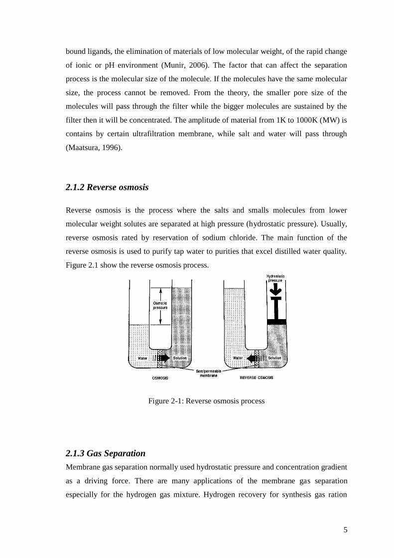
2.1.2 Reverse osmosis
Reverse osmosis is the process where the salts and smalls molecules from lower
molecular weight solutes are separated at high pressure (hydrostatic pressure). Usually,
reverse osmosis rated by reservation of sodium chloride. The main function of the
reverse osmosis is used to purify tap water to purities that excel distilled water quality.
Figure 2.1 show the reverse osmosis process.
Figure 2-1: Reverse osmosis process
2.1.3 Gas Separation
Membrane gas separation normally used hydrostatic pressure and concentration gradient
as a driving force. There are many applications of the membrane gas separation
especially for the hydrogen gas mixture. Hydrogen recovery for synthesis gas ration
6
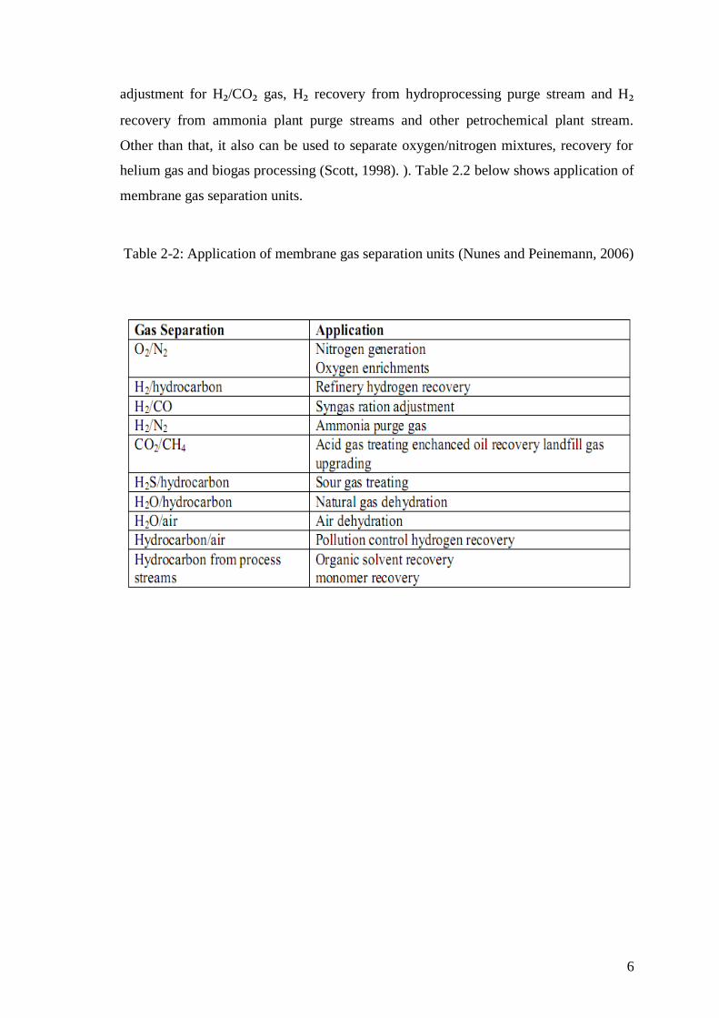
adjustment for H₂/CO₂ gas, H₂ recovery from hydroprocessing purge stream and H₂
recovery from ammonia plant purge streams and other petrochemical plant stream.
Other than that, it also can be used to separate oxygen/nitrogen mixtures, recovery for
helium gas and biogas processing (Scott, 1998). ). Table 2.2 below shows application of
membrane gas separation units.
Table 2-2: Application of membrane gas separation units (Nunes and Peinemann, 2006)
7
2.1.3.1 History of membrane in gas separation system
In 1829, Thomas Graham found the gaseous osmosis for the air carbon dioxide system
through a wet animal bladder. (Kesting and Fritzsche,1993). After that, in 1831 J.K.
Mitchell noted that CO₂ gas was observed by rubber film to a larger degree than other
gases, and was led to infer, accordingly, noticed that rubber expand with volume hence
porosity was induced in solid sample which provide awa of penetration of CO₂
molecules. Then, 1866 Graham’s law of diffusion was found. He describe about
―sorption diffusion‖ theory of gas transport through membrane. In his researched, gas is
permeated through a film (natural rubber) into vacuum not into air. He set up a series of
relative permeation rates across the film for a number of gases that is amazing lose to
modern estimates of the corresponding properties then state that no relation between
these values and known diffusion coefficients in gases. Graham then, test for the first
membrane gas separations and acquire oxygen riched air containing 46.6% oxygen. He
discover that changes in the thickness of films affects the flux but not the composition
of permeate gas. On 1891, Kayser show the validity of Hendry’s law for adsorption of
CO₂ in natural rubber ( Raul and Yampol’ ski, 1994). The information and knowledge
about the gas separation in membrane continues discovered until nowadays.
2.1.3.2 Absorption
Absorption application was found to remove the acid gas such as carbon dioxide and
hydrogen sulphide (Maclean et al, 1986). This process actually is a physical process
where a gas selectively diffused in a liquid and subsequently recovered through the
effect of heat, pressure or chemical. The absorption take place when normal boiling
point of component operated or one or more of component have strong affinity for a
particular solvent. One of the examples the application of absorption is CO₂ removal for
synthesis gas and for scrubbing CO₂ and sulphur compound from natural gas.
8
2.1.3.3 Adsorption
Adsorption process apply the technique porous solid such as zeolite, carbon molecular
sieve and aluminosilicates material to prefer adsorb one gaseous species versus others.
The adsorbent is packed in carbon steel vessels and a higher pressure is used to adsorb
while a lower pressure is used to desorb.
2.1.3.4 Membrane
Membrane is a thin barrier between feed and permeate gas stream and had been used to
carry fluids. Thin asymmetric membranes was first assembly which contain of a thin,
dense, outside layer was formed on a porous base layer, thick and developed from
cellulose acetate (Loeb and Sourirajan, 1963). Gas separation is used to separate the
mixture of gases using porous or non- porous membrane. This mechanism is quite
different of transport involved. Separation of porous membrane is through the difference
in Knudsen flows of component in the pores which are less size than mean free path of
the molecules. Meanwhile, separation of gas through non-porous depend on different in
permeability’s of gases.
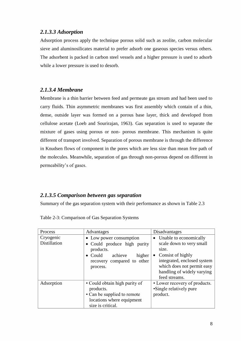
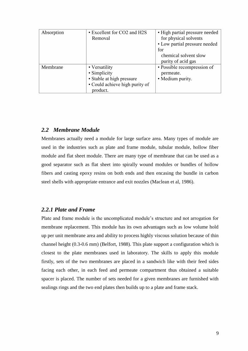
2.1.3.5 Comparison between gas separation
Summary of the gas separation system with their performance as shown in Table 2.3
Table 2-3: Comparison of Gas Separation Systems
Process Advantages Disadvantages
Cryogenic
Distillation Low power consumption
Could produce high purity products.
Could achieve higher recovery compared to other
process.
Unable to economically
scale down to very small
size.
Consist of highly integrated, enclosed system
which does not permit easy
handling of widely varying
feed streams.
Adsorption • Could obtain high purity of
products.
• Can be supplied to remote
locations where equipment
size is critical.
• Lower recovery of products.
•Single relatively pure
product.
9
Absorption • Excellent for CO2 and H2S
Removal
• High partial pressure needed
for physical solvents
• Low partial pressure needed
for
chemical solvent slow
purity of acid gas
Membrane • Versatility
• Simplicity
• Stable at high pressure
• Could achieve high purity of
product.
• Possible recompression of
permeate.
• Medium purity.
2.2 Membrane Module
Membranes actually need a module for large surface area. Many types of module are
used in the industries such as plate and frame module, tubular module, hollow fiber
module and flat sheet module. There are many type of membrane that can be used as a
good separator such as flat sheet into spirally wound modules or bundles of hollow
fibers and casting epoxy resins on both ends and then encasing the bundle in carbon
steel shells with appropriate entrance and exit nozzles (Maclean et al, 1986).
2.2.1 Plate and Frame
Plate and frame module is the uncomplicated module’s structure and not arrogation for
membrane replacement. This module has its own advantages such as low volume hold
up per unit membrane area and ability to process highly viscous solution because of thin
channel height (0.3-0.6 mm) (Belfort, 1988). This plate support a configuration which is
closest to the plate membranes used in laboratory. The skills to apply this module
firstly, sets of the two membranes are placed in a sandwich like with their feed sides
facing each other, in each feed and permeate compartment thus obtained a suitable
spacer is placed. The number of sets needed for a given membranes are furnished with
sealings rings and the two end plates then builds up to a plate and frame stack.
10
2.2.2 Tubular
This module process need a number of membranes of tubular shape are closed in a
container. The feed will flow through the center of the tubes while the permeate flow
through the porous supporting tube into the module housing. Tubular module
configuration commonly introduced by ceramic membrane. Energy consumption
increases to per unit amount of liquid. Unfortunately, this module cannot operate by
itself and need to be supported by a tube from outside.
2.2.3 Hollow Fiber
This module contains of a large number of fibers join together in a module. The self
supporting membrane is suitable to use in this module. There are two arrangement of
this module firstly, inside out where the feed solution passes through the bore of the
fiber and the permeated is collected on the outside of the fiber. Secondly, outside in
where the feed solution enters the module on the shell side of the fibers and the
permeated passes into the fiber bore. Common diameters of hollow fibers are 25-200
µm. Since no breaks or defects are allowed in a module, this requires very high
standards of reproducibility and quality controls (Baker et al., 1991).
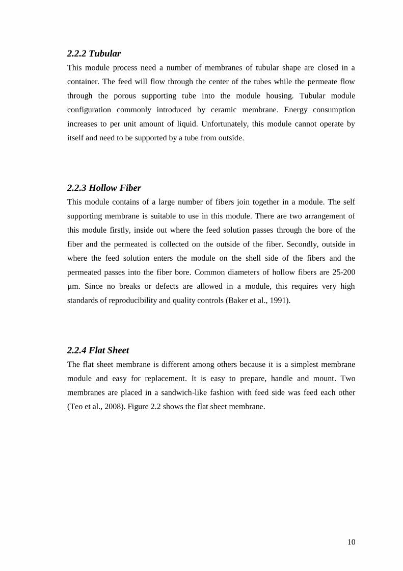
2.2.4 Flat Sheet
The flat sheet membrane is different among others because it is a simplest membrane
module and easy for replacement. It is easy to prepare, handle and mount. Two
membranes are placed in a sandwich-like fashion with feed side was feed each other
(Teo et al., 2008). Figure 2.2 shows the flat sheet membrane.
11
Figure 2-2: flat sheet module
2.3 Membrane Classification
There have a few sample of membrane listed that had been found but most of
them still have the similar main principle and configuration.
2.3.1 Microporous Membrane
Membrane react nearly such a fiber filter and separates by a sieving mechanism
detected by the pore diameter and particle size. Substances such as ceramics,graphite,
metal oxide and polymers were used in making such membranes (Scott et al.,1998).
2.3.2 Electrically Charged Membrane
An ion changing membranes consist of highly swollen gels conducting a fixed positive
or negative charges. These are generally used in the electro dialysis.(Nunes et al., 2003)

12
2.3.3 Assymmetric Membrane
Asymmetric membranes are consumed primarily for pressure driven membrane
processes, such as ultrafiltration and gas separation. Their structure consist of a very
thin (0.1 to 2.0μm) polymer layer on highly porous 100 to 200μm thick sublayer
(Strathmann, 1986). The sublayer only acts as a support and does not affect the
separation characteristics or the permeation rate of the membrane in pressure driven
processes. To obtain high permeation rates, the selective layer of gas separation
membranes must be extremely thin (Baker, 2002). The advantage of asymmetric
membranes is the membranes are surface filters retaining all the rejected materials at the
surface where they can be release by shear forces applied by the feed solution moving
parallel to the membranes surface (Costello, 1994)
2.4 Method to Produce the Membrane
2.4.1 Phase Inversion
This process is a casting solution consisting of polymer and solvent is immersed into a
non-solvent coagulation bath. The mixtures then dissolved causes the casting solution
will go through a phase transition by which the membrane then formed. The phase
inversion process involves two different types of phase transition which is liquid-liquid
phase, two-phase region and solidification phase (Pinnau 1991). There are many type of
phase inversion method such as thermal precipitation, air casting of dope solution,
precipitation from the vapor and immersion precipitation.
2.4.1.1 Immersion Precipitation
Immersion precipitation casting of a polymer as a thin film on a support or extruded
through a die, and is subsequently immersed in a non-solvent bath. Precipitation can
occur because of the good solvent in the polymer solution is exchanged with non-
solvent in the coagulation bath (Fleming, 1998).
13
2.4.1.2 Air Casting of Dope Solution
Air casting technique process used the polymer to dissolve in a mixture of a volatile
solvent and less volatile non solvent. During the evaporation of the solvent, the
solubility of the polymer decreases and then phase separation will occur.
2.4.2 Thermal Phase Induce Separation
Membrane preparation using thermal induce phase separation (TIPS) is the preparation
of membrane includes phase separation of polymers. In the late 1970s and early 1980s,
TIPS was assembly by Castro and then patented by several people for the preparation of
microporous polymeric membranes and used by various companies (Chen et al., 2009).
The advantage of TIPS is suitable for wide applications for semi-crystalline polymer.
On the other hand, the process is flexible, good mechanical properties, thermal stability,
chemical resistance and low cost. TIPS method is operate to formed pore in the
membrane layer. One efficient way to control pore size in the layer by cooling both side
of the uniform solution. Using TIPS the polymer must be mix with diluents. After that,
the membrane will produced and started to be characterized and tested its performance.
14
3 METHODOLOGY
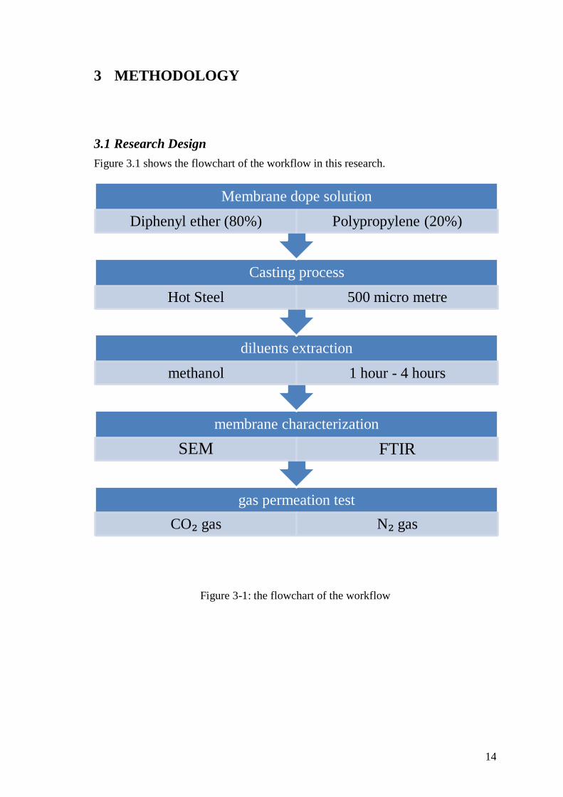
3.1 Research Design
Figure 3.1 shows the flowchart of the workflow in this research.
Figure 3-1: the flowchart of the workflow
gas permeation test
CO₂ gas N₂ gas
membrane characterization
SEM FTIR
diluents extraction
methanol 1 hour - 4 hours
Casting process
Hot Steel 500 micro metre
Membrane dope solution
Diphenyl ether (80%) Polypropylene (20%)

15
3.2 Material Selection
3.2.1 Isotactic Polypropylene (iPP)
Isotactic Polypropylene (iPP) from Sigma Aldrich was used in this experiment. Figure
3.2 below shows the chemical structure of iPP.
Figure 3-2: the chemical structure of iPP
Table 3-1: basic Properties of (iPP).
Properties Values
Melt index 12g/10min(230°C/2.16kg)
Mol wt(g/mol) Average Mw= 250 000
Hardness 100 (Rockwell R, ASTM D
785-A)
Transition Temperature (°C) 160-165
Density (g/mL) 0.9
Melting Point (°C) 160-166