Embed Size (px)
Citation preview
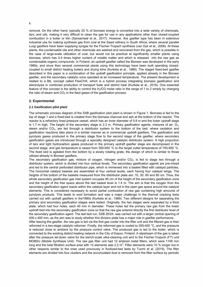
DOI: 10.3303/CET2186002 Paper Received: 28 September 2020; Revised: 28 February 2021; Accepted: 20 April 2021 Please cite this article as: Kurkela E., Kurkela M., Hiltunen I., 2021, Production of Synthesis Gas from Biomass Residues by Staged Fixed-bed Gasification - Results from Pilot Test Campaigns, Chemical Engineering Transactions, 86, 7-12 DOI:10.3303/CET2186002
CHEMICAL ENGINEERING TRANSACTIONS
VOL. 86, 2021
A publication of
The Italian Association
of Chemical Engineering Online at www.cetjournal.it
Guest Editors: Sauro Pierucci, Jiří Jaromír Klemeš Copyright © 2021, AIDIC Servizi S.r.l. ISBN 978-88-95608-84-6; ISSN 2283-9216
Production of Synthesis Gas from Biomass Residues by Staged Fixed-Bed Gasification - Results from Pilot Test
Campaigns Esa Kurkela*, Minna Kurkela, Ilkka Hiltunen VTT Technical Research Centre of Finland Ltd, P.O. Box 1000, FI-02044 VTT, Finland [email protected] Fluidized-bed and entrained-flow gasification systems are developed for large-scale synthesis gas applications with at least 100 MW biomass input. However, there is also a market need for smaller-scale plants, which could be better integrated into energy production systems and local biomass logistics. The staged fixed-bed (SXB) gasifier described in this paper targets a size range of 10-50 MW of feedstock input. The primary gasification stage occurs in an updraft fixed bed. The tar-containing updraft gas is further processed in the secondary gasification zone, where gas temperature is raised from 200-500 °C to 750-900 °C by feeding secondary oxygen through a specially designed catalytic distributor zone. The composition and tar content of the resulting raw gas is similar to that of fluidized-bed gasifiers. Consequently, hot gas filtration, catalytic reforming and final gas cleaning technologies, similar to those recently developed and demonstrated for fluidized-bed gasifiers, can be applied. The results from the 0.5 MW pilot gasification tests carried out with wood, bark and sunflower husk pellets are presented in this paper.
1. Introduction
Advanced transportation biofuels have been the focus of intensive development in Europe since the early 2000s, but industrial deployment of developed technologies has been cancelled or postponed. One fundamental reason for this is the need for extremely large-scale plant concepts in order to exploit economies of scale, improve economic feasibility and attract investors. Large-scale plants also suffer from incomplete utilization of by-product heat, as it is difficult to find sufficiently large heat consumers that could exploit the heat supply to a large degree. Thus, the biomass utilization efficiency of stand-alone plants rarely exceeds 55 % (LHV), even with the best available technologies (Hannula I., Kurkela E., 2013). Although biomass gasification can be realized using many kinds of reactor types, all recent industrially developed Biomass-to-Liquids (BTL) concepts have been based either on entrained flow gasification of pre-treated biomass or fluidized-bed gasification followed by secondary treatment of tars and hydrocarbon gases (Hofbauer et al., 2019). These two basic alternatives aim at large-scale applications with at least 100 MW feedstock input. This paper concentrates on a fixed-bed gasification alternative aiming at 10-50 MW feedstock capacities. By using parallel gasifiers, larger plants can also be considered. Traditionally, fixed-bed biomass gasifiers are used to produce power in small-scale applications (downdraft gasifiers, < 1 MW) or to produce tar-containing gas (updraft, 1-10 MW), which cannot be cleaned for syngas applications (Sansaniwal et al., 2017). Usually, the feedstock basis of downdraft gasifiers is limited to lumpy biomass sources, which have low ash content or high ash melting temperature, as the basic design principle is to achieve efficient thermal tar breakdown in the hot central oxidation zone through which all tars and other pyrolysis products have to pass (Reed T.B & Das A., 1988). This design has several drawbacks: difficulty to scale-up to above 1 MW, ash sintering taking place in the hot oxidation zone and high carbon losses, since the final conversion depends on the char gasification reactions, which are significantly slower than oxidation reactions. The other basic fixed-bed gasifier type, the updraft (counter flow) gasifier, is a simple shaft furnace, in which air or oxygen and steam are introduced to the bottom of the fixed bed through a grate, and biomass is fed from the top. The main advantages of this reactor type are high chemical efficiency using gas and tar, high carbon conversion and fully oxidized ash
7
removal. On the other hand, typically 20 % of biomass energy is converted into a wide variety of chemicals, tars, and oils, making it very difficult to clean the gas for use in any applications other than closed-coupled combustion in a boiler or kiln (Sansaniwal et al., 2017). However, this gasifier type has been in extensive industrial use for making synthesis gas from coal at the Sasol refinery in South Africa, where several parallel Lurgi gasifiers have been supplying syngas for the Fischer-Tropsch synthesis (van Dyk et al., 2006). At these plants, the condensable oils and other chemicals are washed and recovered from the gas, which is possible in the case of large-scale utilization of coal, but would not be practical at significantly smaller plants using biomass, which has 3-4 times higher content of volatile matter and which is released into the raw gas as condensable organic compounds. In Finland, an updraft gasifier called the Bioneer was developed in the early 1980s, and since then several commercial plants using this technology have been built operating closed-coupled to small district heating boilers and drying kilns (Kurkela et al., 1989). The staged fixed-bed gasifier described in this paper is a combination of the updraft gasification principle, applied already in the Bioneer gasifier, and the secondary catalytic zone operated at an increased temperature. The present development is related to a BtL concept called FlexCHX, which is a hybrid process integrating biomass gasification and electrolysis in combined production of transport fuels and district heat (Kurkela et al., 2019). One essential feature of this concept is the ability to control the H2/CO molar ratio in the range of 1 to 2 simply by changing the ratio of steam and CO2 in the feed gases of the gasification process.
2. Experimental
2.1 Gasification pilot plant
The schematic process diagram of the SXB gasification pilot plant is shown in Figure 1. Biomass is fed to the top of stage 1 and a fixed-bed is created from the biomass charcoal and ash at the bottom of the reactor. The reactor is a refractory lined pressure vessel, which has an inner diameter of 0.8 m and the lower updraft stage is 1.7 m high. The height of the secondary stage is 2.3 m. Primary gasification agents, mixtures of air, O2, steam and/or CO2, are fed through a distributor system to the bottom of the bed, where oxidation and gasification reactions take place in a similar manner as in commercial updraft gasifiers. The gasification and pyrolysis gases produced in the primary stage flow to the second stage of the gasifier, where secondary gasification gases are introduced through a specially designed catalytic distributor system. A high proportion of tars and light hydrocarbon gases produced in the primary updraft gasifier stage are decomposed in the second stage, and gas temperature is raised from 300-600 °C to the target outlet temperature of 750-900 °C. The fixed bed is agitated from the bottom by a slowly rotating grate, the design of which is similar to those utilized already in Bioneer gasifiers. The secondary gasification gas, mixture of oxygen, nitrogen and/or CO2, is fed to stage two through a distributor system, which is divided into four vertical levels. The secondary gasification agents are pre-mixed and led to the central perforated distributor pipe, which is immersed into a basket filled with catalyst particles. The horizontal catalyst baskets are assembled at four vertical levels, each having four catalyst wings. The heights of the bottom of the baskets measured from the distributor plate are: 10, 30, 60 and 80 cm. Thus, the whole secondary gasification gas inlet system occupies 90 cm of the height of the secondary gasification zone and the height of the free space above the last basket level is 1.4 m. The aim is that the oxygen from the secondary gasification agent reacts within the catalyst layer and not in the open gas space around the catalyst elements. This is considered necessary to avoid partial combustion of raw gas containing high amounts of pyrolysis products. This leads to soot formation and was a major challenge in the thermal cracking tests carried out with updraft gasifiers in the1980s (Kurkela et al., 1989). Two different designs for separating the primary and secondary gasification stages were tested. Originally, the two stages were separated by a thick plate, which had four holes, each 40 mm in diameter. These holes led the primary raw gas from the lower updraft bed into the secondary gasification zone so that the raw gas entered directly the first distributor level of the secondary gasification agent. The last test run, SXB 20/24, was carried out with a larger central opening of 400 x 400 mm, as the aim was to study whether this division plate has a major role in gasifier performance. After leaving the gasifier, the raw gas is led via the first gas cooler into the filter unit and the filtered gas is then reformed in a two-stage catalytic reformer. Finally, the reformed gas is cooled to 200-400 °C, and the pressure is reduced close to ambient by the pressure control valve. The produced gas is led to the boiler, which is connected to the existing district heating network in the City of Espoo, Finland. A slipstream of the gas is taken after the pressure let-down valve for the bench-scale ultra-cleaning unit and to the Fischer-Tropsch (FT) unit MOBSU (Mobile Synthesis Unit). The raw gas filter unit had 12 sintered metal filters, which were 1108 mm long and the total filtration surface area with 12 elements was 2.2 m2. Filter elements were 10 % longer but in other respects similar to the ones used previously in fluidized-bed tests by Tuomi et al. (2019). The filter elements are divided into four clusters and the accumulated dust is removed from the filter surface by periodic
8
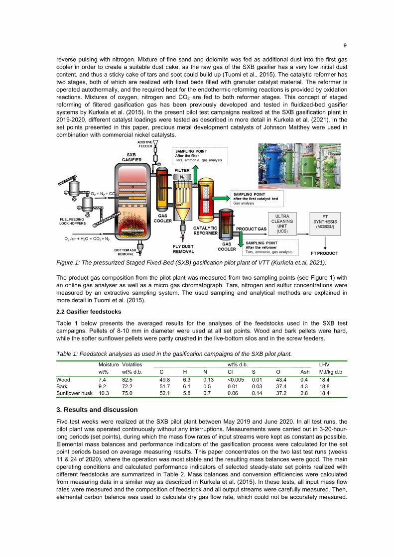
reverse pulsing with nitrogen. Mixture of fine sand and dolomite was fed as additional dust into the first gas cooler in order to create a suitable dust cake, as the raw gas of the SXB gasifier has a very low initial dust content, and thus a sticky cake of tars and soot could build up (Tuomi et al., 2015). The catalytic reformer has two stages, both of which are realized with fixed beds filled with granular catalyst material. The reformer is operated autothermally, and the required heat for the endothermic reforming reactions is provided by oxidation reactions. Mixtures of oxygen, nitrogen and CO2 are fed to both reformer stages. This concept of staged reforming of filtered gasification gas has been previously developed and tested in fluidized-bed gasifier systems by Kurkela et al. (2015). In the present pilot test campaigns realized at the SXB gasification plant in 2019-2020, different catalyst loadings were tested as described in more detail in Kurkela et al. (2021). In the set points presented in this paper, precious metal development catalysts of Johnson Matthey were used in combination with commercial nickel catalysts.
Figure 1: The pressurized Staged Fixed-Bed (SXB) gasification pilot plant of VTT (Kurkela et.al, 2021).
The product gas composition from the pilot plant was measured from two sampling points (see Figure 1) with an online gas analyser as well as a micro gas chromatograph. Tars, nitrogen and sulfur concentrations were measured by an extractive sampling system. The used sampling and analytical methods are explained in more detail in Tuomi et al. (2015).
2.2 Gasifier feedstocks
Table 1 below presents the averaged results for the analyses of the feedstocks used in the SXB test campaigns. Pellets of 8-10 mm in diameter were used at all set points. Wood and bark pellets were hard, while the softer sunflower pellets were partly crushed in the live-bottom silos and in the screw feeders.
Table 1: Feedstock analyses as used in the gasification campaigns of the SXB pilot plant.
Moisture wt%
Volatiles wt% d.b.
C
H
N
wt% d.b. Cl
S
O
Ash
LHV MJ/kg d.b
Wood Bark Sunflower husk
7.4 9.2 10.3
82.5 72.2 75.0
49.8 51.7 52.1
6.3 6.1 5.8
0.13 0.5 0.7
<0.005 0.01 0.06
0.01 0.03 0.14
43.4 37.4 37.2
0.4 4.3 2.8
18.4 18.8 18.4
3. Results and discussion
Five test weeks were realized at the SXB pilot plant between May 2019 and June 2020. In all test runs, the pilot plant was operated continuously without any interruptions. Measurements were carried out in 3-20-hour-long periods (set points), during which the mass flow rates of input streams were kept as constant as possible. Elemental mass balances and performance indicators of the gasification process were calculated for the set point periods based on average measuring results. This paper concentrates on the two last test runs (weeks 11 & 24 of 2020), where the operation was most stable and the resulting mass balances were good. The main operating conditions and calculated performance indicators of selected steady-state set points realized with different feedstocks are summarized in Table 2. Mass balances and conversion efficiencies were calculated from measuring data in a similar way as described in Kurkela et al. (2015). In these tests, all input mass flow rates were measured and the composition of feedstock and all output streams were carefully measured. Then, elemental carbon balance was used to calculate dry gas flow rate, which could not be accurately measured.
9
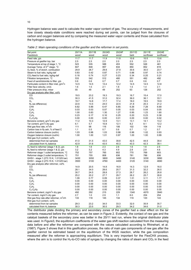
Hydrogen balance was used to calculate the water vapor content of gas. The accuracy of measurements, and how closely steady-state conditions were reached during set points, can be judged from the closures of carbon and oxygen balances and by comparing the measured water vapor contents and those calculated from the hydrogen balance.
Table 2: Main operating conditions of the gasifier and the reformer in set points.
Set point Feedstock
20/11A wood
20/11B wood
20/24D wood
20/24F wood
20/11D bark
20/11E sunflower
20/24E sunflower
Feed rate, g/s 11.7 11.7 11.9 11.9 10.6 10.5 13.6 Pressure at gasifier top, bar 2.5 2.5 2.0 2.0 2.5 2.5 2.0 Temperature at top of stage 1, °C 523 535 588 453 552 526 461 Average Temp. of 2nd stage, °C O2 feed, % of stoich. combustion Steam to fuel ratio, kg/kg-daf CO2-feed to fuel ratio, kg/kg-daf Filtration temperature, °C Feed of sand/dolomite to filter, g/s Particulate content in filter inlet, g/m3n Filter face velocity, cm/s Filter pressure drop, mbar Dry gas analysis after filter, vol% CO CO2 H2 N2 (as difference) CH4 C2H2 C2H4 C2H6 C3-C5Hy Benzene content, g/m3n dry gas Tar content, g/m3n dry gas Wet gas flow rate, m3n/h Carbon loss in fly ash, % of feed C Carbon balance closure (out/in) Oxygen balance closure (out/in) Wet gas H2O content, vol% determined from tar samples calculated from H2 balance
847 29.9 0.83 0.18 533 0.6 14.5 1.6 55 19.5 30.3 19.7 22.6 6.62 0.03 1.00 0.23 0.00 11.2 6.1 111 1.1 1.03 1.00 41.0 42.9
848 28.7 0.42 0.74 542 0.6 14.5 1.5 49 23.2 41.5 14.8 13.5 5.89 0.03 0.83 0.17 0.00 10.3 5.7 98 0.5 0.98 1.00 31.5 31.6
857 29.8 0.87 0.27 512 0.7 13.4 2.1 49 19.3 31.0 17.7 24.0 6.47 0.07 1.30 0.16 0.00 12.9 10.8 116 0.7 1.03 1.01 43.0 43.5
834 27.9 0.71 0.23 480 0.7 12.2 1.8 252 19.3 32.4 17.4 22.5 6.85 0.05 1.27 0.25 0.01 13.1 12.1 106 0.6 0.98 0.97 39.8 40.3
850 30.6 0.88 0.34 551 0.6 14.5 1.5 63 16.7 36.0 18.0 21.8 6.26 0.03 0.95 0.20 0.00 13.1 8.2 102 0.7 0.96 1.00 42.5 43.3
852 30.0 0.97 0.25 482 0.6 14.5 1.4 126 15.4 36.1 19.5 20.3 7.28 0.04 1.23 0.23 0.00 14.1 8.1 104 1.2 1.02 1.00 44.9 42.3
819 23.7 0.74 0.21 492 0.7 12.8 2.1 252 17.0 33.1 19.9 21.2 6.69 0.05 1.60 0.38 0.02 13.2 12.2 118 0.7 0.93 0.99 39.4 39.1
O2 feed to reformer (stage 1 & 2), g/s N2 feed to reformer (stage 1 & 2), g/s Reformer stage 1 outlet temperature, °C Reformer stage 2 outlet temperature, °C GHSV - stage 1 (273.15 K, 1.01325 bar) GHSV - stage 2 (273.15 K, 1.01325 bar) Dry gas analysis after reformer, vol% CO CO2 H2 N2 (as difference) CH4 C2H2 C2H4 C2H6 C3-C5Hy Benzene content, mg/m3n dry gas Tar content, mg/m3n dry gas Wet gas flow rate after reformer, m3n/h Wet gas H2O content, vol% determined from tar samples calculated from H2 balance
1.8 3.2 752 751 3430 3500 14.9 28.1 30.7 25.2 1.09 0.00 0.00 0.00 0.00 492 2.7 133 29.3 30.3
1.6 3.2 757 755 3050 3100 20.5 34.0 24.5 20.2 0.77 0.00 0.00 0.00 0.00 292 1.0 118 23.2 23.5
2.3 4.3 765 808 3800 4760 14.8 28.6 28.8 27.7 0.09 0.00 0.00 0.00 0.00 215 2.9 145 34.0 30.5
2.6 4.9 802 836 3490 4400 16.9 25.7 27.3 29.7 0.37 0.00 0.00 0.00 0.00 229 1.1 134 33.3 29.3
1.6 2.8 770 781 3140 3120 14.3 31.3 26.7 26.2 1.51 0.00 0.00 0.00 0.00 1340 6.0 119 32.0 34.2
1.6 2.8 769 786 3230 3140 12.9 32.2 26.2 25.7 3.11 0.00 0.00 0.00 0.00 4570 204 120 35.9 34.6
2.5 4.6 803 836 3890 4690 16.0 26.5 26.8 28.8 1.77 0.00 0.00 0.00 0.00 3940 254 143 35.7 31.0
The distributor plate dividing the primary and secondary zones of the gasifier had a clear effect on the tar contents measured before the reformer, as can be seen in Figure 2. Evidently, the contact of raw gas and the catalyst baskets of the secondary zone was better in the 20/11 test run, where the original distributor plate was used. In Figure3, the equilibrium coefficients of the water gas shift reaction calculated from the measuring data before and after the reformer are compared with the values calculated according to Rhinehart, et al. (1987). Figure 3 shows that in this gasification process, the ratio of main gas components of raw gas after the gasifier cannot be estimated based on the equilibrium of the WGS reaction, while the gas composition measured after the reformer is approaching equilibrium. This is very important for the FlexCHX process, where the aim is to control the H2-to-CO ratio of syngas by changing the ratios of steam and CO2 in the feed
10

gases of the gasification process. In test run 20/24, the reformer was operated with ca. 50 °C higher outlet temperature than used in test 20/11. In addition, the loading of the second bed contained only a small amount of nickel and more precious metal catalyst, which explains higher conversions achieved in the reformer. The conversions achieved in the reformer, presented in Figure 4, indicate that the effect of sulfur was similar, as reported in the fluidized-bed gasification tests of Kurkela et al. (2015). However, the results obtained with low-sulfur wood fuels were clearly better and the reformer could be operated at 100 °C lower temperature. Figure 5 presents the calculated conversion efficiencies from input biomass to the syngas components and tars based on lower heating values. The raw gas before reforming has high concentrations of tars and hydrocarbon gases and only 36-42 % of the input biomass energy is converted to syngas components CO and H2.
Figure 2: Tar and benzene concentrations in dry gas. Figure 3: Comparison of measured and calculated equilibrium coefficients of shift reaction.
After the reformer, the sum of LHV of CO and H2 represents already 66 % of biomass energy input, while the efficiency is lower in the case of sunflower husk due to lower methane conversion. When comparing the CO and H2 contents (see Table 2) and the energy distributions (Figure 5) for set points 20/11A and 20/1B, it can be noticed that the H2/CO ratio could be decreased from ca. 2 to 1.2 by replacing part of the gasification steam with CO2. This pushed the equilibrium towards a higher CO content and did not have any negative impacts on gasifier performance or tars contents.
Figure 4: Conversion efficiencies of tars, benzene, Figure 5: Conversion of biomass energy to gas CH4 and C2-hydrocarbons at selected set points. before and after reformer (based on LHV). Two key challenges of this type of gasification process are the formation of sticky filter cake, which can make it impossible to clean the filter by pulse cleaning, and the formation of soot deposits on the catalyst beds of the reformer. Both problems result in increasing pressure drop. In test run 20/11, as well as in previous tests where the distribution plate was used in between the gasifier stages, filtration was smooth and a stable pressure drop could be maintained as shown in Figure 6A. This shows that, mainly depending on the flow rate, the pressure drop returns to the same level after each pulse cleaning. In test run 20/24, filter pressure drop gradually increased in some of the set points, evidently due to higher tar and soot contents (Figure 6 B). In both tests, a mixture of fine dolomite and sand was fed to the raw gas before the filter inlet in order to assist cake build-up and cleaning. In both test runs, the pressure drop of the reformer was stable and reformer conversions also remained stable.
11
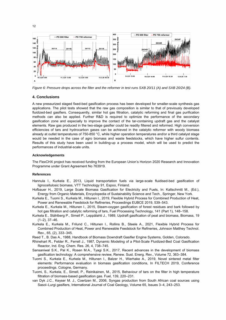
Figure 6: Pressure drops across the filter and the reformer in test runs SXB 20/11 (A) and SXB 20/24 (B).
4. Conclusions
A new pressurized staged fixed-bed gasification process has been developed for smaller-scale synthesis gas applications. The pilot tests showed that the raw gas composition is similar to that of previously developed fluidized-bed gasifiers. Consequently, similar hot gas filtration, catalytic reforming and final gas purification methods can also be applied. Further R&D is required to optimize the performance of the secondary gasification zone and especially to improve the contact of the tar-containing updraft gas and the catalyst elements. Raw gas produced in the two-stage gasifier could be readily filtered and reformed. High conversion efficiencies of tars and hydrocarbon gases can be achieved in the catalytic reformer with woody biomass already at outlet temperatures of 750-850 °C, while higher operation temperatures and/or a third catalyst stage would be needed in the case of agro biomass and waste feedstocks, which have higher sulfur contents. Results of this study have been used in building-up a process model, which will be used to predict the performances of industrial-scale units.
Acknowledgements
The FlexCHX project has received funding from the European Union’s Horizon 2020 Research and Innovation Programme under Grant Agreement No 763919.
References
Hannula I., Kurkela E., 2013, Liquid transportation fuels via large-scale fluidised-bed gasification of lignocellulosic biomass, VTT Technology 91, Espoo, Finland.
Hofbauer H., 2019, Large Scale Biomass Gasification for Electricity and Fuels, In: Kaltschmitt M., (Ed.), Energy from Organic Materials, Encyclopedia of Sustainability Science and Tech., Springer, New York.
Kurkela E., Tuomi S., Kurkela M., Hiltunen I., 2019, Flexible Hybrid Process for Combined Production of Heat, Power and Renewable Feedstock for Refineries, Proceedings EUBCE 2019, 539–543.
Kurkela E., Kurkela M., Hiltunen I., 2015, Steam-oxygen gasification of forest residues and bark followed by hot gas filtration and catalytic reforming of tars, Fuel Processing Technology, 141 (Part 1), 148–158.
Kurkela E., Ståhlberg P., Simell P., Leppälahti J., 1989, Updraft gasification of peat and biomass, Biomass, 19 (1–2), 37–46.
Kurkela E., Kurkela M., Frilund C., Hiltunen I., Rollins B., Steele A., 2021, Flexible Hybrid Process for Combined Production of Heat, Power and Renewable Feedstock for Refineries, Johnson Matthey Technol. Rev., 65, (2), 333–345.
Reed T., B. Das A., 1988, Handbook of Biomass Downdraft Gasifier Engine Systems, Golden, Colorado. Rhinehart R., Felder R., Ferrell J., 1987, Dynamic Modeling of a Pilot-Scale Fluidized-Bed Coal Gasification
Reactor, Ind. Eng. Chem. Res. 26, 4, 738–745. Sansaniwal S.K., Pal K., Rosen M.A., Tyagi S.K., 2017, Recent advances in the development of biomass
gasification technology: A comprehensive review, Renew. Sust. Energ. Rev., Volume 72, 363–384. Tuomi S., Kurkela E., Kurkela M., Hiltunen I., Balzer H., Wierhake A., 2019, Novel sintered metal filter
elements: Performance evaluation in biomass gasification conditions, In FILTECH 2019, Conference proceedings. Cologne, Germany.
Tuomi, S., Kurkela, E., Simell, P., Reinikainen, M., 2015, Behaviour of tars on the filter in high temperature filtration of biomass-based gasification gas. Fuel, 139, 220–231.
van Dyk J.C., Keyser M. J., Coertzen M., 2006, Syngas production from South African coal sources using Sasol–Lurgi gasifiers, International Journal of Coal Geology, Volume 65, Issues 3–4, 243–253.
12