Embed Size (px)
Citation preview
Programmable Controllers
User'(FX2N-32CAN Com
F
MITSUBISHI ELEC
MITSUBISHI ELECTRIC
01 05 2006JY992D92801Version B
s Manual
munication Module)X2N
TRIC INDUSTRIAL AUTOMATION

FX2N-32CAN Communication Module
i
FX2N-32CANCommunication Module
USER’S MANUAL
This manual confers no industrial property rights or any rights of any other kind, nor does it confer any patentlicenses. Mitsubishi Electric Corporation cannot be held responsible for any problems involving industrialproperty rights which may occur as a result of using the contents noted in this manual.
Manual number : JY992D92801
Manual revision : B
Date : MAY 2006
FX2N-32CAN Communication Module

FX2N-32CAN Communication Module
ii
FAX BACK
Mitsubishi has a world wide reputation for its efforts in continually developing and pushing backthe frontiers of industrial automation. What is sometimes overlooked by the user is the careand attention to detail that is taken with the documentation. However, to continue this processof improvement, the comments of the Mitsubishi users are always welcomed. This page hasbeen designed for you, the reader, to fill in your comments and fax them back to us. We lookforward to hearing from you.
Fax numbers: Your name....................................................
Mitsubishi Electric.... .....................................................................
America (01) 847-478-2253 Your company ..............................................
Australia (02) 638-7072 .....................................................................
Germany (0 21 02) 4 86-1 12 Your location:................................................
South Africa (0 27) 11 444-0223 .....................................................................
United Kingdom (01707) 278-695
Please tick the box of your choice
What condition did the manual arrive in? Good Minor damage Unusable
Will you be using a folder to store the manual? Yes No
What do you think to the manual presentation? Tidy Unfriendly
Are the explanations understandable? Yes Not too bad Unusable
Which explanation was most difficult to understand: ......................................................................................................................................................................................................................
Are there any diagrams which are not clear? Yes No
If so,which: ..................................................................................................................................
What do you think to the manual layout? Good Not too bad Unhelpful
If there one thing you would like to see improved, what is it? .............................................................................................................................................................................................................................................................................................................................................................
Could you find the information you required easily using the index and/or the contents, ifpossible please identify your experience: ...................................................................................................................................................................................................................................................................................................................................................................................................................................................................................................................................................................................................................................................................................................
Do you have any comments in general about the Mitsubishi manuals? .....................................................................................................................................................................................................................................................................................................................................................................................................................................................................................................................................................................................................................................................
Thank you for taking the time to fill out this questionnaire. We hope you found both the productand this manual easy to use.
FX2N-32CAN Communication Module
iii

FX2N-32CAN Communication Module
iv
FX2N-32CAN Communication Module
Guidelines for the Safety of the User and Protection of the Programmable Controller
This manual provides information for the use of the FX2N-32CAN Communication Module. Themanual has been written to be used by trained and competent personnel. The definition ofsuch a person or persons is as follows;
a) Any engineer who is responsible for the planning, design and construction of automaticequipment using the product associated with this manual should be of a competentnature, trained and qualified to the local and national standards required to fulfill thatrole. These engineers should be fully aware of all aspects of safety with regards toautomated equipment.
b) Any commissioning or service engineer must be of a competent nature, trained andqualified to the local and national standards required to fulfill that job. These engineersshould also be trained in the use and maintenance of the completed product. Thisincludes being completely familiar with all associated documentation for the said product.All maintenance should be carried out in accordance with established safety practices.
c) All operators of the completed equipment should be trained to use that product in a safeand coordinated manner in compliance to established safety practices. The operatorsshould also be familiar with documentation which is connected with the actual operationof the completed equipment.
Note : Note: the term ‘completed equipment’ refers to a third party constructed device whichcontains or uses the product associated with this manual.
Notes on the Symbols Used in this Manual
At various times through out this manual certain symbols will be used to highlight points ofinformation which are intended to ensure the users personal safety and protect the integrity ofequipment. Whenever any of the following symbols are encountered its associated note mustbe read and understood. Each of the symbols used will now be listed with a brief description ofits meaning.
Hardware Warnings
1) Indicates that the identified danger WILL cause physical and property damage.
2) Indicates that the identified danger could POSSIBLY cause physical and propertydamage.
3) Indicates a point of further interest or further explanation.
Software Warnings
4) Indicates special care must be taken when using this element of software.
5) Indicates a special point which the user of the associate software element shouldbe aware of.
6) Indicates a point of interest or further explanation.
v
FX2N-32CAN Communication Module
• Under no circumstances will Mitsubishi Electric be liable responsible for any consequentialdamage that may arise as a result of the installation or use of this equipment.
• All examples and diagrams shown in this manual are intended only as an aid tounderstanding the text, not to guarantee operation. Mitsubishi Electric will accept noresponsibility for actual use of the product based on these illustrative examples.
• Owing to the very great variety in possible application of this equipment, you must satisfyyourself as to its suitability for your specific application.
vi
FX2N-32CAN Communication Module
Note Concerning the CE Marking
This document does not guarantee that a mechanical system including this product will complywith the following standards. Compliance to EMC standards of the entire mechanical systemshould be checked by the user / manufacturer. Compliance to LVD standards of the entiremechanical system should be checked by the user / manufacturer.
EMC
The following products have shown compliance through direct testing (of the identifiedstandards below) and design analysis (through the creation of a technical construction file) tothe European Directive for Electromagnetic Compatibility (89/336/EEC) when used as directedby the appropriate documentation. Refer to a manual or related material of each product otherthan the following.
Type : Programmable Controller (Open Type Equipment)
Models : FX2N-32CAN manufactured
from November 1st, 2001 to April 30th, 2006 arecompliant with EN50081-2 and EN61131-2:1994+A11:1996after May 1st, 2006 are compliant with EN61131-2:2003
For more details, please contact the local Mitsubishi Electric sales site.
- Note for using the FX2N-32CANFor complicance to EC EMC directive, install the FX2N main unit, extension unit/block andthe FX2N-32CAN in a shielded metal cabinet.
Standard Remark
EN50081-2:1993 Electromagnetic compatibility- Generic emission standard
Industrial environment
Compliance with all relevant aspects of the standard.(Radiated Emissions)
EN61131-2:1994 Programmable controllers /A11:1996 - Equipment requirements and tests
Compliance with all relevant aspects of the standard.(RF Immunity, Fast Transients , ESD and Damped oscillatory wave)
EN61131-2:2003 Programmable controllers- Equipment requirements
and tests
Compliance with all relevant aspects of the standard.(Radiated Emissions, Mains Terminal VoltageEmissions, RF immunity, Fast Transients, ESD, Surge, Voltage drops and interruptions, Conducted and Power magnetic fields)
vii

FX2N-32CAN Communication Module
viii
edgaerhtyy
Table of Contents
Guideline of Safty.................................................................................v
1. Introduction............................................................................................1-11.1 Associated Manuals ............................................................................................ 1-11.2 General Names and Abbreviations...................................................................... 1-2
2. Overview ...............................................................................................2-12.1 Overview of the CANopen Network ..................................................................... 2-12.2 Overview of FX2N-32CAN Communication Module ............................................ 2-12.3 Characteristics ..................................................................................................... 2-2
2.3.1 Communication with other CANopen Nodes............................................................. 2-22.3.2 The Object Dictionary ................................................................................................ 2-22.3.3 SDO Command ......................................................................................................... 2-22.3.4 The Command Interface............................................................................................ 2-22.3.5 Node Guarding .......................................................................................................... 2-2
3. Specification ..........................................................................................3-13.1 Environmental/Standards Specifications ............................................................. 3-13.2 Power Supply Specifications ............................................................................... 3-13.3 Performance Specification................................................................................... 3-2
4. Buffer Memory Structure/Parameter Setup ...........................................4-14.1 Basic Buffer Memory Structure, BFM0 ~ BFM31 ................................................ 4-14.2 Buffer Memory Functions .................................................................................... 4-1
4.2.1 Data Transfer Locations, BFMs 0~19 and 100~199 ................................................. 4-14.2.2 The Data Exchange Mode, BFM 20 .......................................................................... 4-14.2.3 Setting the Baud Rate, BFM 24................................................................................. 4-24.2.4 Reading the Communication Status, BFM 25 ........................................................... 4-24.2.5 The Watch Dog Timer Setting, BFM 26 .................................................................... 4-34.2.6 The Node Address, BFM 27...................................................................................... 4-34.2.7 Error Staus, BFM 29.................................................................................................. 4-44.2.8 BFM Data Memory Backup ....................................................................................... 4-4
4.3 Extended BFM Structure, BFM32 ~ BFM32767 .................................................. 4-5
5. The Object Dictionary............................................................................5-15.1 BFM access to the Object Dictionary - Write TO................................................. 5-15.2 BFM access to the Object Dictionary - Read FROM ........................................... 5-35.3 CANopen Object Dictionary Structure ................................................................. 5-4
5.3.1 The General Setup .................................................................................................... 5-45.3.2 The Detailed Object Dictionary Contents (According to DS-301*) ............................ 5-4
ix
edgaerhtyy
6. The Command Interface........................................................................6-16.1 SDO Read Request ............................................................................................. 6-16.2 SDO Write Request ............................................................................................. 6-26.3 Layer 2 Messages ............................................................................................... 6-3
6.3.1 The PDO Remote Transmission Request ................................................................. 6-46.4 Error Messages ................................................................................................... 6-5
6.4.1 General Error Messages .......................................................................................... 6-56.4.2 Local SDO Error Codes (BFM1001 = 3).................................................................... 6-66.4.3 Remote SDO Error Codes (BFM1001 = 3)................................................................ 6-66.4.4 Unknown Command Used (BFM1001 = 100) ........................................................... 6-76.4.5 Queue was not available (BFM1001 = 8FFFF hex) .................................................. 6-76.4.6 Command or Parameter Change while CIF was busy (BFM1001 = FFFF hex)........ 6-76.4.7 The Clear/Reset “CIF was busy” Error ...................................................................... 6-76.4.8 CIF Internal Error (BFM1001 = 200 hex)................................................................... 6-8
7. The Mapping Modes..............................................................................7-17.1 Factory Default Mapping/Mode 0 Mapping.......................................................... 7-27.2 Mode A Mapping ................................................................................................. 7-27.3 Mode B Mapping ................................................................................................. 7-3
7.3.1 Prepare the PDO Mapping Table .............................................................................. 7-37.3.2 The Source Command .............................................................................................. 7-57.3.3 The Destination Parameter ....................................................................................... 7-57.3.4 Assign Additional COB-IDs to the Local Node ......................................................... 7-67.3.5 The End of the Parameter Table ............................................................................... 7-6
7.4 PDO Mapping Table Overviews .......................................................................... 7-77.4.1 Tx-PDO Mapping Table............................................................................................. 7-77.4.2 Rx-PDO Mapping Table ............................................................................................ 7-87.4.3 Mode B Mapping Errors ............................................................................................ 7-97.4.4 Source Parameter Errors .......................................................................................... 7-97.4.5 Destination Parameter Errors .................................................................................. 7-107.4.6 Other Errors............................................................................................................. 7-10
8. Node Guarding ......................................................................................8-18.1 CIF/BFM Structure for Slave Guarding Assignment ............................................ 8-18.2 Node Guarding Parameter Settings .................................................................... 8-1
8.2.1 Slave Number............................................................................................................ 8-18.2.2 Services Requested .................................................................................................. 8-28.2.3 Guard Time ............................................................................................................... 8-28.2.4 Number of Retries ..................................................................................................... 8-28.2.5 End of Parameter Table ............................................................................................ 8-28.2.6 Parameter Errors....................................................................................................... 8-28.2.7 Read Guarding Status............................................................................................... 8-38.2.8 Reset Guarding Status Latch .................................................................................... 8-4
9. Emergency Messages...........................................................................9-19.1 Read Emergency Message Buffers ..................................................................... 9-19.2 Send an Emergency Message ............................................................................ 9-3
x
Introduction 1FX2N-32CAN Communication Module
1. Introduction
1.1 Associated Manuals
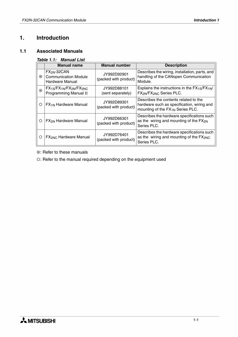
: Refer to these manuals
: Refer to the manual required depending on the equipment used
Table 1.1: Manual ListManual name Manual number Description
FX2N-32CAN Communication Module Hardware Manual
JY992D92901(packed with product)
Describes the wiring, installation, parts, and handling of the CANopen Communication Module.
FX1S/FX1N/FX2N/FX2NCProgramming Manual ΙΙ
JY992D88101 (sent separately)
Explains the instructions in the FX1S/FX1N/FX2N/FX2NC Series PLC.
FX1N Hardware ManualJY992D89301
(packed with product)
Describes the contents related to the hardware such as specification, wiring and mounting of the FX1N Series PLC.
FX2N Hardware Manual JY992D66301(packed with product)
Describes the hardware specifications such as the wiring and mounting of the FX2N Series PLC.
FX2NC Hardware Manual JY992D76401(packed with product)
Describes the hardware specifications such as the wiring and mounting of the FX2NC Series PLC.
1-1
FX2N-32CAN Communication Module Introduction 1
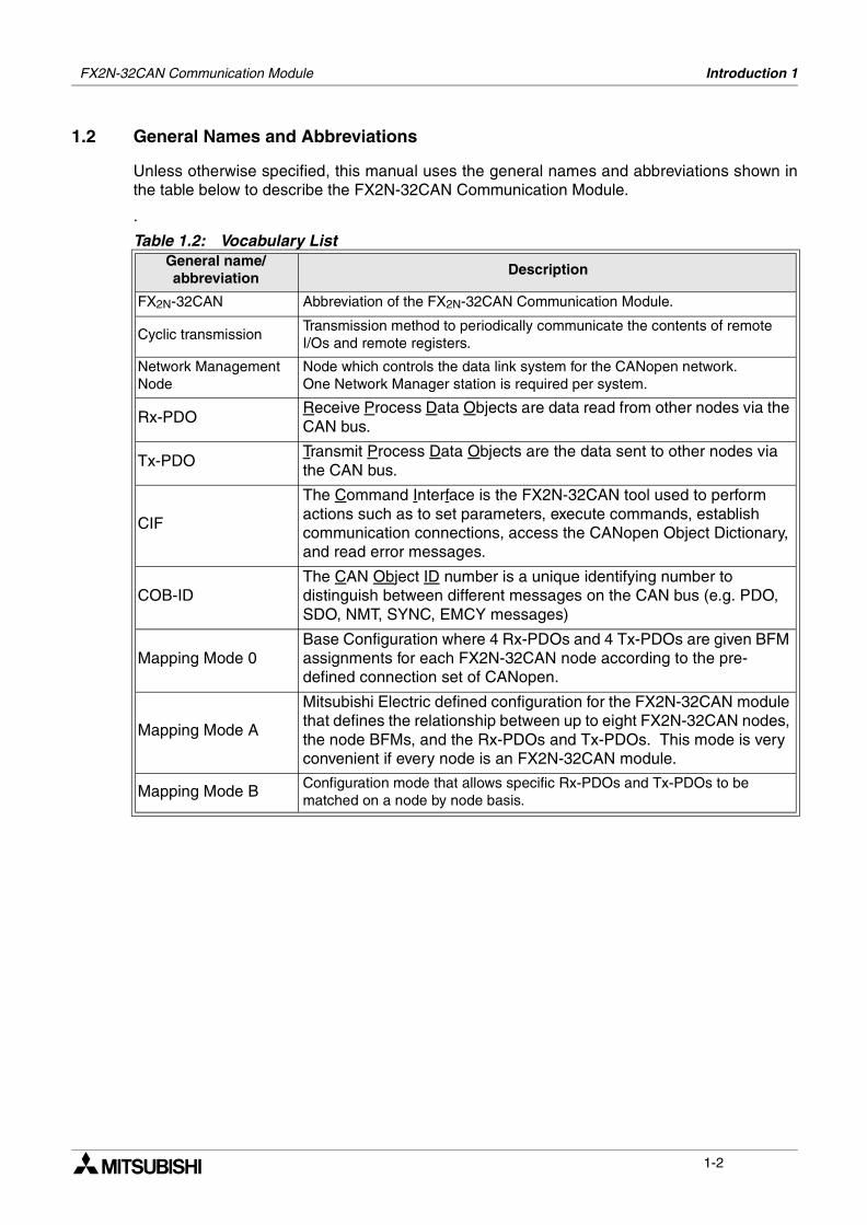
1.2 General Names and Abbreviations
Unless otherwise specified, this manual uses the general names and abbreviations shown inthe table below to describe the FX2N-32CAN Communication Module.
.
Table 1.2: Vocabulary ListGeneral name/abbreviation
Description
FX2N-32CAN Abbreviation of the FX2N-32CAN Communication Module.
Cyclic transmissionTransmission method to periodically communicate the contents of remote I/Os and remote registers.
Network Management Node
Node which controls the data link system for the CANopen network. One Network Manager station is required per system.
Rx-PDOReceive Process Data Objects are data read from other nodes via the CAN bus.
Tx-PDOTransmit Process Data Objects are the data sent to other nodes via the CAN bus.
CIF
The Command Interface is the FX2N-32CAN tool used to perform actions such as to set parameters, execute commands, establish communication connections, access the CANopen Object Dictionary, and read error messages.
COB-IDThe CAN Object ID number is a unique identifying number to distinguish between different messages on the CAN bus (e.g. PDO, SDO, NMT, SYNC, EMCY messages)
Mapping Mode 0Base Configuration where 4 Rx-PDOs and 4 Tx-PDOs are given BFM assignments for each FX2N-32CAN node according to the pre-defined connection set of CANopen.
Mapping Mode A
Mitsubishi Electric defined configuration for the FX2N-32CAN module that defines the relationship between up to eight FX2N-32CAN nodes, the node BFMs, and the Rx-PDOs and Tx-PDOs. This mode is very convenient if every node is an FX2N-32CAN module.
Mapping Mode B Configuration mode that allows specific Rx-PDOs and Tx-PDOs to be matched on a node by node basis.
1-2
Overview 2FX2N-32CAN Communication Module
2. Overview
This chapter describes the overview of the FX2N-32CAN Communication Module for theFX1N/2N(c) Series PLC.The Controller Area Network (CAN used hereafter in this manual) is a serial bus systemespecially suited for networking "intelligent" devices as well as sensors and actuators within asystem or sub-system.
2.1 Overview of the CANopen Network
The CANopen protocol provides a system for transferring serial messages between differentnodes via the CAN bus.
1) Simple, relatively high speed communication can be accomplished with modules thathandle the ON/OFF data such as I/Os or numeric data.
2) All CAN nodes are able to transmit data and several nodes can make a request to the CANbus simultaneously.
3) Connections can be made to different types of devices made by partner manufacturersgiving flexibility to the system.
4) Messages can be prioritized for transfer to the CAN Bus.
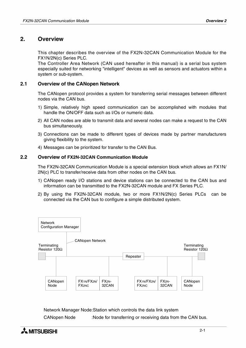
2.2 Overview of FX2N-32CAN Communication Module
The FX2N-32CAN Communication Module is a special extension block which allows an FX1N/2N(c) PLC to transfer/receive data from other nodes on the CAN bus.
1) CANopen ready I/O stations and device stations can be connected to the CAN bus andinformation can be transmitted to the FX2N-32CAN module and FX Series PLC.
2) By using the FX2N-32CAN module, two or more FX1N/2N(c) Series PLCs can beconnected via the CAN bus to configure a simple distributed system.
Network Manager Node:Station which controls the data link system
CANopen Node :Node for transferring or receiving data from the CAN bus.
NetworkConfiguration Manager
CANopenNode
FX1N/FX2N/FX2NC
FX2N-32CAN
FX1N/FX2N/FX2NC
FX2N-32CAN
TerminatingResistor 120Ω
CANopen Network
Repeater
CANopenNode
TerminatingResistor 120Ω
2-1
FX2N-32CAN Communication Module Overview 2
2.3 Characteristics
This section describes the characteristics of the CAN bus, communication with other CANopennodes, and some of the special features available in the CANopen protocol.
2.3.1 Communication with other CANopen Nodes
All nodes on the CAN network can write data to the all the other nodes on the network. Eachpiece of data has a unique identifiying number that is read by the receiving nodes to determinewhether that data should be kept in the receiving nodes’ Buffer Memory.
The FX2N-32CAN module has separate buffer memories for writing TO and reading FROM theCAN bus. These Buffer Memories are accessed by FROM/TO commands of the PLC.
2.3.2 The Object Dictionary
The Object Dictionary is a kind of indexed storage system that contains data, deviceparameters, CANopen feature setup data, instruction triggers, and other informationnecessary to configure and operate the CANopen protocol.
2.3.3 SDO Command
The Service Data Object Command can be used to read/write data to the Object Dictionary.This command can be used to set network parameters and also to initiate CANopenfunctionality.
2.3.4 The Command Interface
The Command Interface is a set of Buffer Memories that is used when using the SDOCommand. The data placed in these BFMs is used to access the parameter setup of theObject Dictionary.
2.3.5 Node Guarding
The nodes on a CAN bus can be checked for their communication status at user definedintervals. If a problem occurs or communication is blocked for some reason, an error messagewill be generated to alert the user to the situation.
2-2
Specification 3FX2N-32CAN Communication Module
3. Specification
3.1 Environmental/Standards Specifications
3.2 Power Supply Specifications
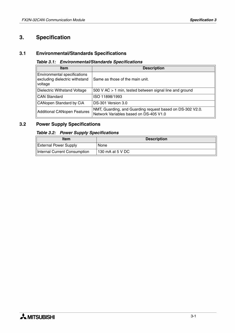
Table 3.1: Environmental/Standards SpecificationsItem Description
Environmental specifications excluding dielectric withstand voltage
Same as those of the main unit.
Dielectric Withstand Voltage 500 V AC > 1 min, tested between signal line and ground
CAN Standard ISO 11898/1993
CANopen Standard by CiA DS-301 Version 3.0
Additional CANopen FeaturesNMT, Guarding, and Guarding request based on DS-302 V2.0.Network Variables based on DS-405 V1.0
Table 3.2: Power Supply SpecificationsItem Description
External Power Supply None
Internal Current Consumption 130 mA at 5 V DC
3-1
FX2N-32CAN Communication Module Specification 3
3.3 Performance Specification
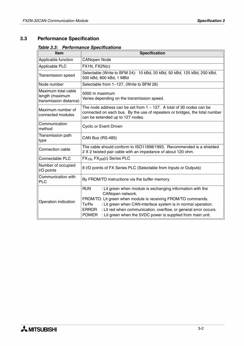
Table 3.3: Performance SpecificationsItem Specification
Applicable function CANopen Node
Applicable PLC FX1N, FX2N(c)
Transmission speedSelectable (Write to BFM 24): 10 kBd, 20 kBd, 50 kBd, 125 kBd, 250 kBd, 500 kBd, 800 kBd, 1 MBd
Node number Selectable from 1~127, (Write to BFM 26)
Maximum total cable length (maximum transmission distance)
5000 m maximumVaries depending on the transmission speed.
Maximum number of connected modules
The node address can be set from 1 ~ 127. A total of 30 nodes can be connected on each bus. By the use of repeaters or bridges, the total number can be extended up to 127 nodes.
Communication method
Cyclic or Event Driven
Transmission path type
CAN Bus (RS-485)
Connection cableThe cable should conform to ISO11898/1993. Recommended is a shielded 2 X 2 twisted pair cable with an impedance of about 120 ohm.
Connectable PLC FX1N, FX2N(c) Series PLC
Number of occupied I/O points
8 I/O points of FX Series PLC (Selectable from Inputs or Outputs)
Communication with PLC
By FROM/TO instructions via the buffer memory
Operation indication
RUN : Lit green when module is exchanging information with the CANopen network.FROM/TO: Lit green when module is receiving FROM/TO commands.Tx/Rx : Lit green when CAN-interface system is in normal operation.ERROR : Lit red when communication, overflow, or general error occurs.POWER : Lit green when the 5VDC power is supplied from main unit.
3-2
Buffer Memory Structure/Parameter Setup 4FX2N-32CAN Communication Module
4. Buffer Memory Structure/Parameter Setup
This chapter describes Buffer Memory Structure of the FX2N-32CAN module and the how toset the parameters associated with the CANopen protocol.
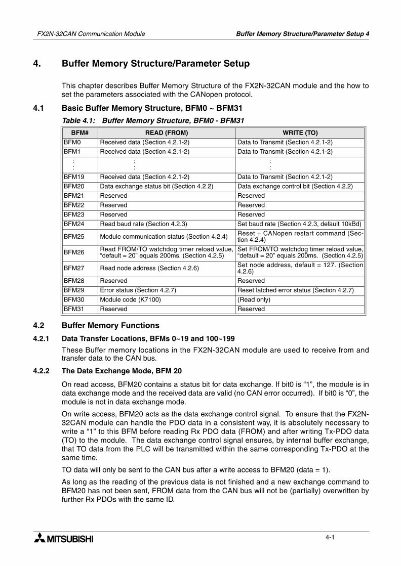
4.1 Basic Buffer Memory Structure, BFM0 ~ BFM31
4.2 Buffer Memory Functions
4.2.1 Data Transfer Locations, BFMs 0~19 and 100~199
These Buffer memory locations in the FX2N-32CAN module are used to receive from andtransfer data to the CAN bus.
4.2.2 The Data Exchange Mode, BFM 20
On read access, BFM20 contains a status bit for data exchange. If bit0 is “1”, the module is indata exchange mode and the received data are valid (no CAN error occurred). If bit0 is “0”, themodule is not in data exchange mode.
On write access, BFM20 acts as the data exchange control signal. To ensure that the FX2N-32CAN module can handle the PDO data in a consistent way, it is absolutely necessary towrite a “1” to this BFM before reading Rx PDO data (FROM) and after writing Tx-PDO data(TO) to the module. The data exchange control signal ensures, by internal buffer exchange,that TO data from the PLC will be transmitted within the same corresponding Tx-PDO at thesame time.
TO data will only be sent to the CAN bus after a write access to BFM20 (data = 1).
As long as the reading of the previous data is not finished and a new exchange command toBFM20 has not been sent, FROM data from the CAN bus will not be (partially) overwritten byfurther Rx PDOs with the same ID.
Table 4.1: Buffer Memory Structure, BFM0 - BFM31
BFM# READ (FROM) WRITE (TO)BFM0 Received data (Section 4.2.1-2) Data to Transmit (Section 4.2.1-2)
BFM1 Received data (Section 4.2.1-2) Data to Transmit (Section 4.2.1-2)
: :
: :
: :
BFM19 Received data (Section 4.2.1-2) Data to Transmit (Section 4.2.1-2)
BFM20 Data exchange status bit (Section 4.2.2) Data exchange control bit (Section 4.2.2)
BFM21 Reserved Reserved
BFM22 Reserved Reserved
BFM23 Reserved Reserved
BFM24 Read baud rate (Section 4.2.3) Set baud rate (Section 4.2.3, default 10kBd)
BFM25 Module communication status (Section 4.2.4) Reset + CANopen restart command (Sec-tion 4.2.4)
BFM26 Read FROM/TO watchdog timer reload value,“default = 20” equals 200ms. (Section 4.2.5)
Set FROM/TO watchdog timer reload value,“default = 20” equals 200ms. (Section 4.2.5)
BFM27 Read node address (Section 4.2.6) Set node address, default = 127. (Section4.2.6)
BFM28 Reserved Reserved
BFM29 Error status (Section 4.2.7) Reset latched error status (Section 4.2.7)
BFM30 Module code (K7100) (Read only)
BFM31 Reserved Reserved
4-1
FX2N-32CAN Communication Module Buffer Memory Structure/Parameter Setup 4
If the CANopen module is in data exchange mode, the received PDO data (Rx-PDO) fromother nodes can be read by the FX2N(C)/FX1N PLC by using a FROM instruction and thetransmit PDO data (Tx-PDO) can be written to the module and sent to the network by using aTO instruction.
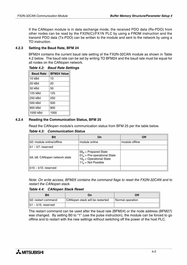
4.2.3 Setting the Baud Rate, BFM 24
BFM24 contains the current baud rate setting of the FX2N-32CAN module as shown in Table4.2 below. The baud rate can be set by writing TO BFM24 and the baud rate must be equal forall nodes on the CANopen network.
4.2.4 Reading the Communication Status, BFM 25
Read the CANopen module’s communication status from BFM 25 per the table below.
Note: On write access, BFM25 contains the command flags to reset the FX2N-32CAN and torestart the CANopen stack.
The restart command can be used after the baud rate (BFM24) or the node address (BFM27)was changed. By setting B0 to “1” (use the pulse instruction), the module can be forced to gooffline and to restart with the new settings without switching off the power of the host PLC.
Table 4.2: Baud Rate Settings
Baud Rate BFM24 Value
10 kBd 10
20 kBd 20
50 kBd 50
125 kBd 125
250 kBd 250
500 kBd 500
800 kBd 800
1000 kBd 1000
Table 4.3: Communication Status
Bit On Off
b0: module online/offline module online module offline
b1 ~ b7: reserved
b9, b8: CANopen network state
00b = Prepared State01b = Pre-operational State10b = Operational State11b = Not Possible
b10 ~ b15: reserved
Table 4.4: CANopen Stack Reset
Bit On Off
b0: restart command CANopen stack will be restarted Normal operation
b1 ~ b15: reserved
4-2
FX2N-32CAN Communication Module Buffer Memory Structure/Parameter Setup 4
4.2.5 The Watch Dog Timer Setting, BFM 26
The Watch Dog Timer setting is stored in BFM 26 in units of 10 ms. A WDT error will occur ifthere is no FROM or TO instruction to any BFM for the time specified. After the WDT hasexpired, it must be reset by writing the current or a new value to BFM26. When the value 0 iswritten to BFM26, the FROM/TO watchdog timer is disabled.
During normal operation as soon as the module receives a FROM or TO instruction, the WDTwill reset to time zero.
Note: No Emergency Message will be transmitted if the WDT is disabled and the FROM/TOcommunication stops and the FX2N-32CAN module is in operational mode.
4.2.6 The Node Address, BFM 27
The CANopen node supports setting of the node address by the FX2N(C)/FX1N PLC via theTO instruction. The actual address is displayed in BFM27. The Node address must be set forcommunication to take place via the CAN bus.
In case of an address change by TO instruction, the new address value (1...127d) must bewritten to BFM27. The new address will only become effective after a power down of the hostPLC or after a restart command written to BFM25.
4-3
FX2N-32CAN Communication Module Buffer Memory Structure/Parameter Setup 4
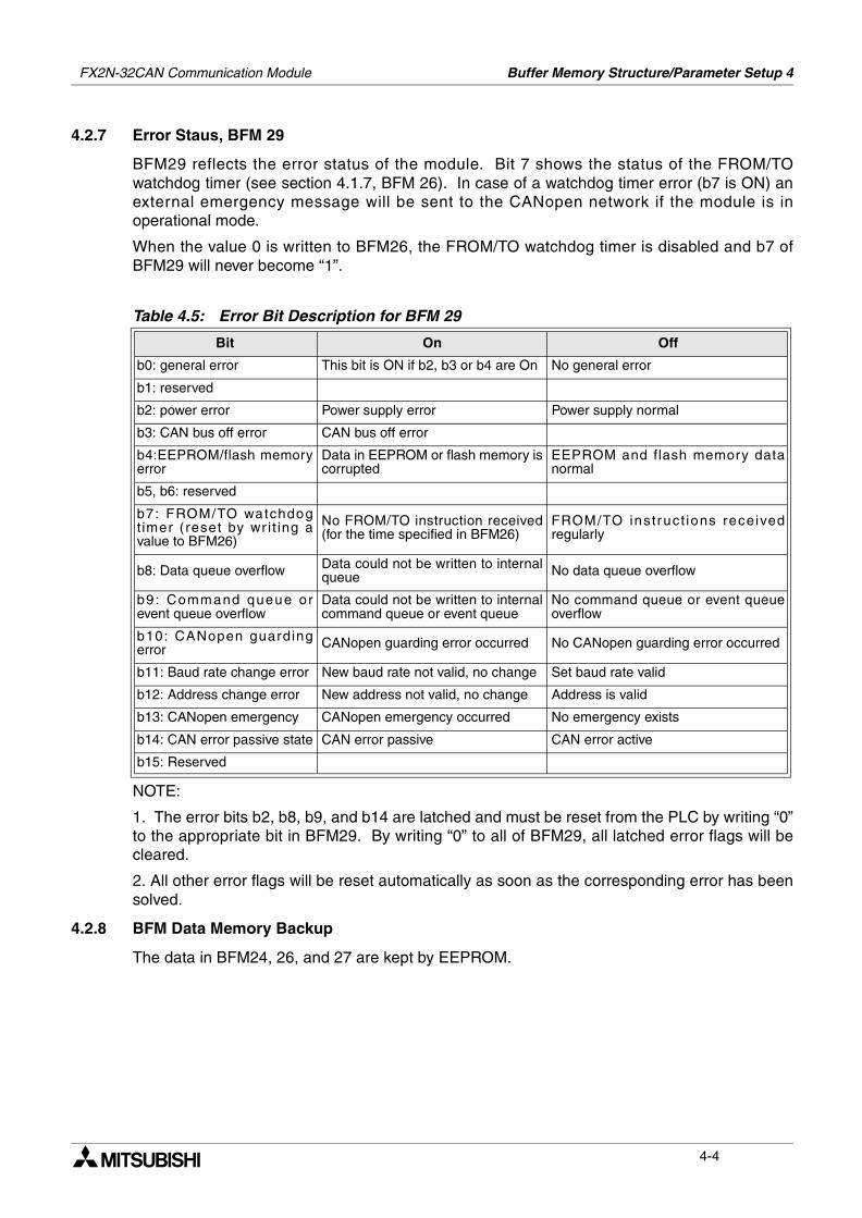
4.2.7 Error Staus, BFM 29
BFM29 reflects the error status of the module. Bit 7 shows the status of the FROM/TOwatchdog timer (see section 4.1.7, BFM 26). In case of a watchdog timer error (b7 is ON) anexternal emergency message will be sent to the CANopen network if the module is inoperational mode.
When the value 0 is written to BFM26, the FROM/TO watchdog timer is disabled and b7 ofBFM29 will never become “1”.
NOTE:
1. The error bits b2, b8, b9, and b14 are latched and must be reset from the PLC by writing “0”to the appropriate bit in BFM29. By writing “0” to all of BFM29, all latched error flags will becleared.
2. All other error flags will be reset automatically as soon as the corresponding error has beensolved.
4.2.8 BFM Data Memory Backup
The data in BFM24, 26, and 27 are kept by EEPROM.
Table 4.5: Error Bit Description for BFM 29
Bit On Off
b0: general error This bit is ON if b2, b3 or b4 are On No general error
b1: reserved
b2: power error Power supply error Power supply normal
b3: CAN bus off error CAN bus off error
b4:EEPROM/flash memoryerror
Data in EEPROM or flash memory iscorrupted
EEPROM and flash memory datanormal
b5, b6: reserved
b7: FROM/TO watchdogtimer (reset by wr i t ing avalue to BFM26)
No FROM/TO instruction received(for the time specified in BFM26)
FROM/TO instruct ions receivedregularly
b8: Data queue overflow Data could not be written to internalqueue No data queue overflow
b9: Command queue orevent queue overflow
Data could not be written to internalcommand queue or event queue
No command queue or event queueoverflow
b10: CANopen guardingerror CANopen guarding error occurred No CANopen guarding error occurred
b11: Baud rate change error New baud rate not valid, no change Set baud rate valid
b12: Address change error New address not valid, no change Address is valid
b13: CANopen emergency CANopen emergency occurred No emergency exists
b14: CAN error passive state CAN error passive CAN error active
b15: Reserved
4-4
FX2N-32CAN Communication Module Buffer Memory Structure/Parameter Setup 4
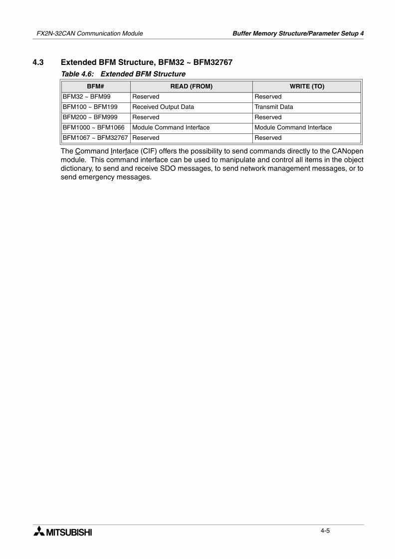
4.3 Extended BFM Structure, BFM32 ~ BFM32767
The Command Interface (CIF) offers the possibility to send commands directly to the CANopenmodule. This command interface can be used to manipulate and control all items in the objectdictionary, to send and receive SDO messages, to send network management messages, or tosend emergency messages.
Table 4.6: Extended BFM Structure
BFM# READ (FROM) WRITE (TO)
BFM32 ~ BFM99 Reserved Reserved
BFM100 ~ BFM199 Received Output Data Transmit Data
BFM200 ~ BFM999 Reserved Reserved
BFM1000 ~ BFM1066 Module Command Interface Module Command Interface
BFM1067 ~ BFM32767 Reserved Reserved
4-5
FX2N-32CAN Communication Module Buffer Memory Structure/Parameter Setup 4
MEMO
4-6
The Object Dictionary 5FX2N-32CAN Communication Module
5. The Object Dictionary
The Object Dictionary is a structure for data organization within the CAN bus. The data withinthe Object Dictionary can be used to set CAN bus parameters, initialize special functions,control data flow, to store data in many formats or send emergency messages.
The Object Dictionary address consists of an Index and Sub-Index for data Read/Write.Different indexes are used depending upon the type of data to store - unsigned 8 bit, signed 8bit, unsigned 16 bit, signed 16 bit, unsigned 32 bit, signed 32 bit, or 32 bit floating point.
The information contained in Sections 5.1 and 5.2 detail how the FX2N-32CAN module BFMscan tranfer information TO/FROM the Object Dictionary Mapping. For the complete structureof the CANopen Object Dictionary, please go to the CAN-in-Automation website at http://www.can-cia.de.
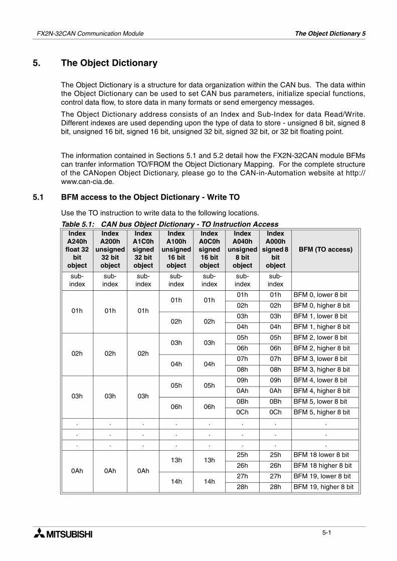
5.1 BFM access to the Object Dictionary - Write TO
Use the TO instruction to write data to the following locations.
Table 5.1: CAN bus Object Dictionary - TO Instruction AccessIndex A240h float 32
bit object
Index A200h
unsigned 32 bit object
Index A1C0h signed 32 bit object
Index A100h
unsigned 16 bit object
Index A0C0h signed 16 bit object
Index A040h
unsigned 8 bit
object
Index A000h
signed 8 bit
object
BFM (TO access)
sub-index
sub-index
sub-index
sub-index
sub-index
sub-index
sub-index
01h 01h 01h
01h 01h01h 01h BFM 0, lower 8 bit
02h 02h BFM 0, higher 8 bit
02h 02h03h 03h BFM 1, lower 8 bit
04h 04h BFM 1, higher 8 bit
02h 02h 02h
03h 03h05h 05h BFM 2, lower 8 bit
06h 06h BFM 2, higher 8 bit
04h 04h07h 07h BFM 3, lower 8 bit
08h 08h BFM 3, higher 8 bit
03h 03h 03h
05h 05h09h 09h BFM 4, lower 8 bit
0Ah 0Ah BFM 4, higher 8 bit
06h 06h0Bh 0Bh BFM 5, lower 8 bit
0Ch 0Ch BFM 5, higher 8 bit
. . . . . . . .
. . . . . . . .
. . . . . . . .
0Ah 0Ah 0Ah
13h 13h25h 25h BFM 18 lower 8 bit
26h 26h BFM 18 higher 8 bit
14h 14h27h 27h BFM 19, lower 8 bit
28h 28h BFM 19, higher 8 bit
5-1
FX2N-32CAN Communication Module The Object Dictionary 5
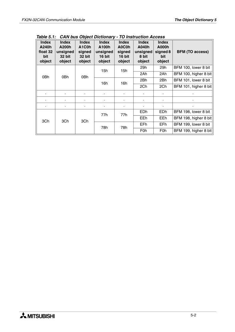
0Bh 0Bh 0Bh
15h 15h29h 29h BFM 100, lower 8 bit
2Ah 2Ah BFM 100, higher 8 bit
16h 16h2Bh 2Bh BFM 101, lower 8 bit
2Ch 2Ch BFM 101, higher 8 bit
. . . . . . . .
. . . . . . . .
. . . . . . . .
3Ch 3Ch 3Ch
77h 77hEDh EDh BFM 198, lower 8 bit
EEh EEh BFM 198, higher 8 bit
78h 78hEFh EFh BFM 199, lower 8 bit
F0h F0h BFM 199, higher 8 bit
Table 5.1: CAN bus Object Dictionary - TO Instruction AccessIndex A240h float 32
bit object
Index A200h
unsigned 32 bit object
Index A1C0h signed 32 bit object
Index A100h
unsigned 16 bit object
Index A0C0h signed 16 bit object
Index A040h
unsigned 8 bit
object
Index A000h
signed 8 bit
object
BFM (TO access)
5-2
FX2N-32CAN Communication Module The Object Dictionary 5
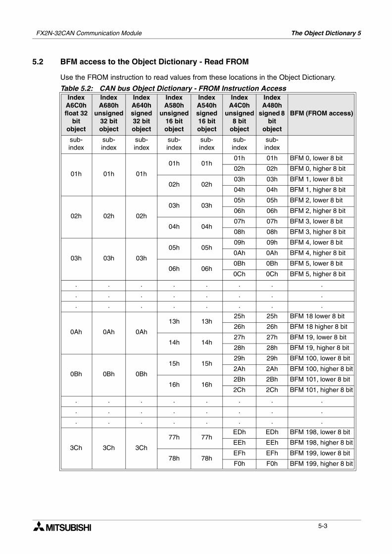
5.2 BFM access to the Object Dictionary - Read FROM
Use the FROM instruction to read values from these locations in the Object Dictionary.
Table 5.2: CAN bus Object Dictionary - FROM Instruction AccessIndex
A6C0h float 32
bit object
Index A680h
unsigned 32 bit object
Index A640h signed 32 bit object
Index A580h
unsigned 16 bit object
Index A540h signed 16 bit object
Index A4C0h
unsigned 8 bit
object
Index A480h
signed 8 bit
object
BFM (FROM access)
sub-index
sub-index
sub-index
sub-index
sub-index
sub-index
sub-index
01h 01h 01h
01h 01h01h 01h BFM 0, lower 8 bit
02h 02h BFM 0, higher 8 bit
02h 02h03h 03h BFM 1, lower 8 bit
04h 04h BFM 1, higher 8 bit
02h 02h 02h
03h 03h05h 05h BFM 2, lower 8 bit
06h 06h BFM 2, higher 8 bit
04h 04h07h 07h BFM 3, lower 8 bit
08h 08h BFM 3, higher 8 bit
03h 03h 03h
05h 05h09h 09h BFM 4, lower 8 bit
0Ah 0Ah BFM 4, higher 8 bit
06h 06h0Bh 0Bh BFM 5, lower 8 bit
0Ch 0Ch BFM 5, higher 8 bit
. . . . . . . .
. . . . . . . .
. . . . . . . .
0Ah 0Ah 0Ah
13h 13h25h 25h BFM 18 lower 8 bit
26h 26h BFM 18 higher 8 bit
14h 14h27h 27h BFM 19, lower 8 bit
28h 28h BFM 19, higher 8 bit
0Bh 0Bh 0Bh
15h 15h29h 29h BFM 100, lower 8 bit
2Ah 2Ah BFM 100, higher 8 bit
16h 16h2Bh 2Bh BFM 101, lower 8 bit
2Ch 2Ch BFM 101, higher 8 bit
. . . . . . . .
. . . . . . . .
. . . . . . . .
3Ch 3Ch 3Ch
77h 77hEDh EDh BFM 198, lower 8 bit
EEh EEh BFM 198, higher 8 bit
78h 78hEFh EFh BFM 199, lower 8 bit
F0h F0h BFM 199, higher 8 bit
5-3
FX2N-32CAN Communication Module The Object Dictionary 5
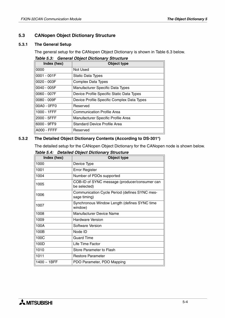
5.3 CANopen Object Dictionary Structure
5.3.1 The General Setup
The general setup for the CANopen Object Dictionary is shown in Table 6.3 below.
5.3.2 The Detailed Object Dictionary Contents (According to DS-301*)
The detailed setup for the CANopen Object Dictionary for the CANopen node is shown below.
Table 5.3: General Object Dictionary StructureIndex (hex) Object type
0000 Not Used
0001 - 001F Static Data Types
0020 - 003F Complex Data Types
0040 - 005F Manufacturer Specific Data Types
0060 - 007F Device Profile Specific Static Data Types
0080 - 009F Device Profile Specific Complex Data Types
00A0 - 0FF0 Reserved
1000 - 1FFF Communication Profile Area
2000 - 5FFF Manufacturer Specific Profile Area
6000 - 9FF9 Standard Device Profile Area
A000 - FFFF Reserved
Table 5.4: Detailed Object Dictionary StructureIndex (hex) Object type
1000 Device Type
1001 Error Register
1004 Number of PDOs supported
1005COB-ID of SYNC message (producer/consumer can be selected)
1006Communication Cycle Period (defines SYNC mes-sage timing)
1007Synchronous Window Length (defines SYNC time window)
1008 Manufacturer Device Name
1009 Hardware Version
100A Software Version
100B Node ID
100C Guard Time
100D Life Time Factor
1010 Store Parameter to Flash
1011 Restore Parameter
1400 ~ 1BFF PDO Parameter, PDO Mapping
5-4
The Command Interface 6FX2N-32CAN Communication Module
6. The Command Interface
The Command Interface (CIF) is located in BFMs 1000~1066 and can be used to access theCANopen Object Dictionary to perform the following commands:
SDO Read Request - Read the value of an index/subindex of the Object Dictionary (local ornetwork node).
SDO Write Request - Write a value to an index/subindex of the Object Dictionary (local ornetwork node).
LAYER 2 message write Request - Write a layer 2 message to the CAN bus.
Local Receive PDO Refresh - Request a transmission of a local Rx-PDO to the network.
Define/Change the PDO Mapping/Binding of the Network
Setup the Guarding Parameter
Read the Guarding Status
Reset the Guarding Status Latch
Read the Emergency Message Buffer
Clear the Emergency Message Buffer
6.1 SDO Read Request
The SDO (Service Data Object) command can access all nodes on the CAN network via theObject Dictionary by using FROM/TO commands using the appropriate BFMs.
A PLC can access the connected FX2N-32CAN module by writing the actual module address(1~127) or by writing “0” in the FROM/TO command.
To initialize the SDO Read command, the value of the node address must be written to BFM1001, the Object Dictionary Index to BFM 1002, and the Subindex to BFM 1003. Finally, thecommand code for SDO Read Access, “4” , must be written to BFM1000.
If the access has been successful BFM1000 will display “5”, BFM 1003 will contain the nodeaddress, index and subindex numbers for verification purposes. The length of the read data (inbytes) will be stored in BFM1004 and BFM1005~BFM1063 will contain up to 118 data bytes.
Byte order: 1st data byte = BFM1005 low byte, 2nd data byte = BFM1005 high byte, 3rd databyte = BFM1006 low byte, 4th data byte = BFM1006 high byte, etc.
6-1
FX2N-32CAN Communication Module The Command Interface 6
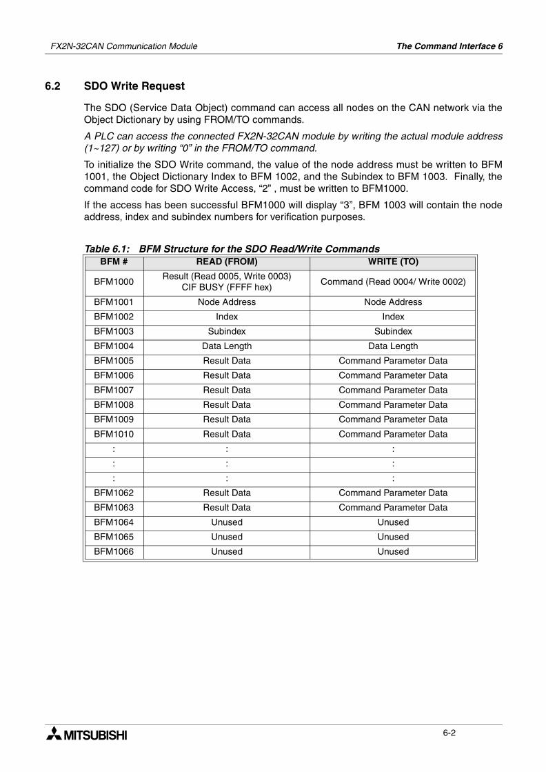
6.2 SDO Write Request
The SDO (Service Data Object) command can access all nodes on the CAN network via theObject Dictionary by using FROM/TO commands.
A PLC can access the connected FX2N-32CAN module by writing the actual module address(1~127) or by writing “0” in the FROM/TO command.
To initialize the SDO Write command, the value of the node address must be written to BFM1001, the Object Dictionary Index to BFM 1002, and the Subindex to BFM 1003. Finally, thecommand code for SDO Write Access, “2” , must be written to BFM1000.
If the access has been successful BFM1000 will display “3”, BFM 1003 will contain the nodeaddress, index and subindex numbers for verification purposes.
Table 6.1: BFM Structure for the SDO Read/Write CommandsBFM # READ (FROM) WRITE (TO)
BFM1000Result (Read 0005, Write 0003)
CIF BUSY (FFFF hex)Command (Read 0004/ Write 0002)
BFM1001 Node Address Node Address
BFM1002 Index Index
BFM1003 Subindex Subindex
BFM1004 Data Length Data Length
BFM1005 Result Data Command Parameter Data
BFM1006 Result Data Command Parameter Data
BFM1007 Result Data Command Parameter Data
BFM1008 Result Data Command Parameter Data
BFM1009 Result Data Command Parameter Data
BFM1010 Result Data Command Parameter Data
: : :
: : :
: : :
BFM1062 Result Data Command Parameter Data
BFM1063 Result Data Command Parameter Data
BFM1064 Unused Unused
BFM1065 Unused Unused
BFM1066 Unused Unused
6-2
FX2N-32CAN Communication Module The Command Interface 6
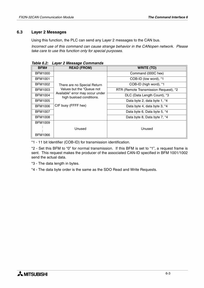
6.3 Layer 2 Messages
Using this function, the PLC can send any Layer 2 messages to the CAN bus.
Incorrect use of this command can cause strange behavior in the CANopen network. Pleasetake care to use this function only for special purposes.
*1 - 11 bit Identifier (COB-ID) for transmission identification.
*2 - Set this BFM to “0” for normal transmission. If this BFM is set to “1”, a request frame issent. This request makes the producer of the associated CAN-ID specified in BFM 1001/1002send the actual data.
*3 - The data length in bytes.
*4 - The data byte order is the same as the SDO Read and Write Requests.
Table 6.2: Layer 2 Message CommandsBFM# READ (FROM) WRITE (TO)
BFM1000
There are no Special Return Values but the “Queue not
Available” error may occur under high busload conditions.
CIF busy (FFFF hex)
Command (000C hex)
BFM1001 COB-ID (low word), *1
BFM1002 COB-ID (high word), *1
BFM1003 RTR (Remote Transmission Request), *2
BFM1004 DLC (Data Length Count), *3
BFM1005 Data byte 2, data byte 1, *4
BFM1006 Data byte 4, data byte 3, *4
BFM1007 Data byte 6, Data byte 5, *4
BFM1008 Data byte 8, Data byte 7, *4
BFM1009::
BFM1066
Unused Unused
6-3
FX2N-32CAN Communication Module The Command Interface 6
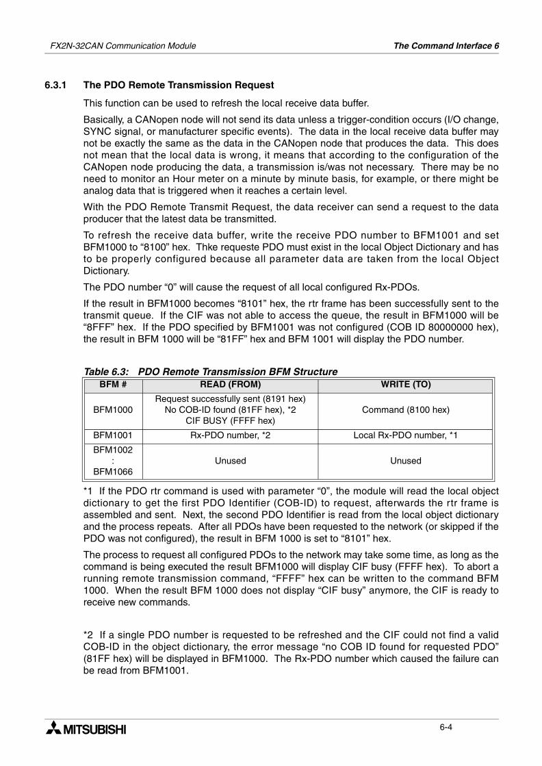
6.3.1 The PDO Remote Transmission Request
This function can be used to refresh the local receive data buffer.
Basically, a CANopen node will not send its data unless a trigger-condition occurs (I/O change,SYNC signal, or manufacturer specific events). The data in the local receive data buffer maynot be exactly the same as the data in the CANopen node that produces the data. This doesnot mean that the local data is wrong, it means that according to the configuration of theCANopen node producing the data, a transmission is/was not necessary. There may be noneed to monitor an Hour meter on a minute by minute basis, for example, or there might beanalog data that is triggered when it reaches a certain level.
With the PDO Remote Transmit Request, the data receiver can send a request to the dataproducer that the latest data be transmitted.
To refresh the receive data buffer, write the receive PDO number to BFM1001 and setBFM1000 to “8100” hex. Thke requeste PDO must exist in the local Object Dictionary and hasto be properly configured because all parameter data are taken from the local ObjectDictionary.
The PDO number “0” will cause the request of all local configured Rx-PDOs.
If the result in BFM1000 becomes “8101” hex, the rtr frame has been successfully sent to thetransmit queue. If the CIF was not able to access the queue, the result in BFM1000 will be“8FFF” hex. If the PDO specified by BFM1001 was not configured (COB ID 80000000 hex),the result in BFM 1000 will be “81FF” hex and BFM 1001 will display the PDO number.
*1 If the PDO rtr command is used with parameter “0”, the module will read the local objectdictionary to get the first PDO Identifier (COB-ID) to request, afterwards the rtr frame isassembled and sent. Next, the second PDO Identifier is read from the local object dictionaryand the process repeats. After all PDOs have been requested to the network (or skipped if thePDO was not configured), the result in BFM 1000 is set to “8101” hex.
The process to request all configured PDOs to the network may take some time, as long as thecommand is being executed the result BFM1000 will display CIF busy (FFFF hex). To abort arunning remote transmission command, “FFFF” hex can be written to the command BFM1000. When the result BFM 1000 does not display “CIF busy” anymore, the CIF is ready toreceive new commands.
*2 If a single PDO number is requested to be refreshed and the CIF could not find a validCOB-ID in the object dictionary, the error message “no COB ID found for requested PDO”(81FF hex) will be displayed in BFM1000. The Rx-PDO number which caused the failure canbe read from BFM1001.
Table 6.3: PDO Remote Transmission BFM StructureBFM # READ (FROM) WRITE (TO)
BFM1000Request successfully sent (8191 hex)
No COB-ID found (81FF hex), *2CIF BUSY (FFFF hex)
Command (8100 hex)
BFM1001 Rx-PDO number, *2 Local Rx-PDO number, *1
BFM1002:
BFM1066Unused Unused
6-4
FX2N-32CAN Communication Module The Command Interface 6
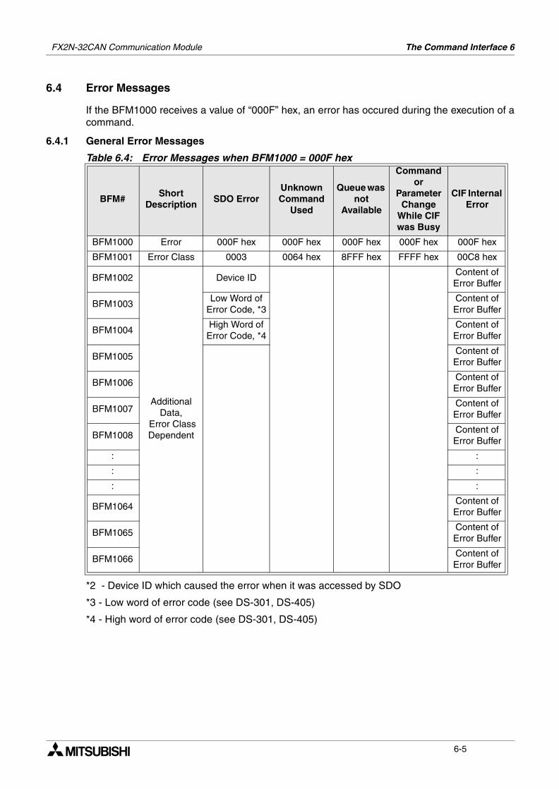
6.4 Error Messages
If the BFM1000 receives a value of “000F” hex, an error has occured during the execution of acommand.
6.4.1 General Error Messages
*2 - Device ID which caused the error when it was accessed by SDO
*3 - Low word of error code (see DS-301, DS-405)
*4 - High word of error code (see DS-301, DS-405)
Table 6.4: Error Messages when BFM1000 = 000F hex
BFM#Short
DescriptionSDO Error
Unknown Command
Used
Queue was not
Available
Command or
Parameter Change
While CIF was Busy
CIF Internal Error
BFM1000 Error 000F hex 000F hex 000F hex 000F hex 000F hex
BFM1001 Error Class 0003 0064 hex 8FFF hex FFFF hex 00C8 hex
BFM1002
Additional Data,
Error Class Dependent
Device IDContent of Error Buffer
BFM1003Low Word of
Error Code, *3Content of Error Buffer
BFM1004High Word of
Error Code, *4Content of Error Buffer
BFM1005Content of Error Buffer
BFM1006Content of Error Buffer
BFM1007Content of Error Buffer
BFM1008Content of Error Buffer
: :
: :
: :
BFM1064Content of Error Buffer
BFM1065Content of Error Buffer
BFM1066Content of Error Buffer
6-5
FX2N-32CAN Communication Module The Command Interface 6
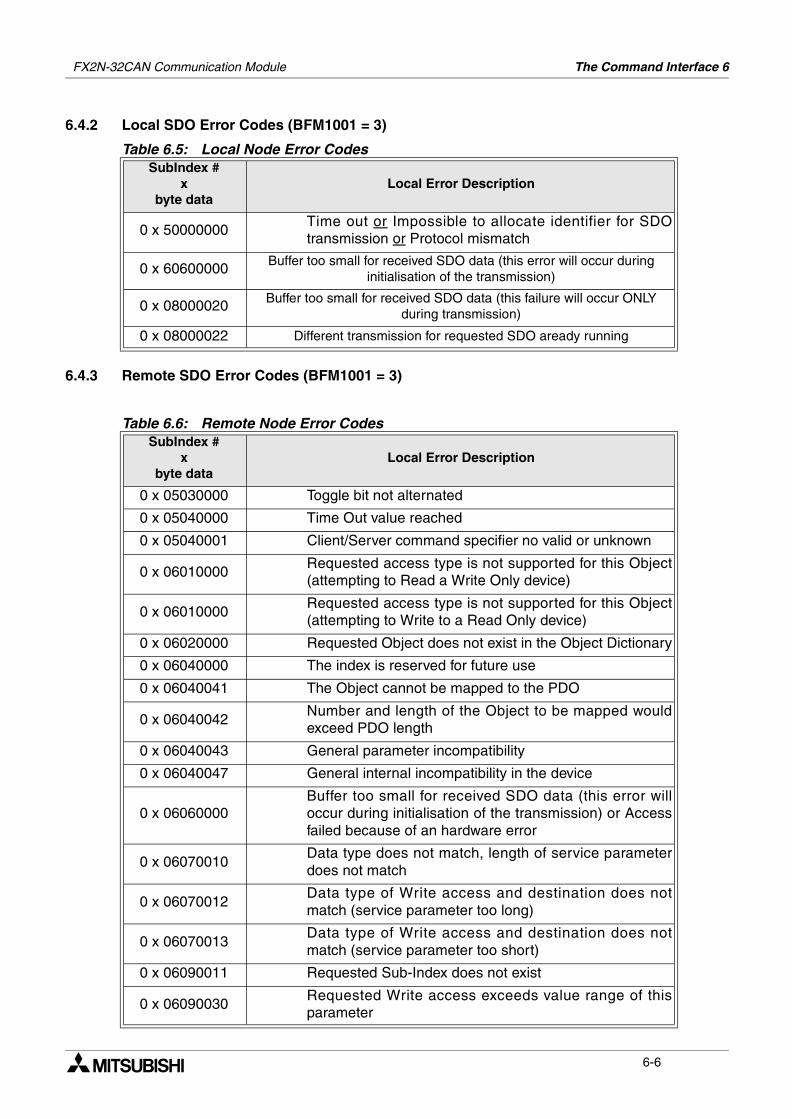
6.4.2 Local SDO Error Codes (BFM1001 = 3)
6.4.3 Remote SDO Error Codes (BFM1001 = 3)
Table 6.5: Local Node Error CodesSubIndex #
x byte data
Local Error Description
0 x 50000000Time out or Impossible to allocate identifier for SDOtransmission or Protocol mismatch
0 x 60600000 Buffer too small for received SDO data (this error will occur during initialisation of the transmission)
0 x 08000020 Buffer too small for received SDO data (this failure will occur ONLY during transmission)
0 x 08000022 Different transmission for requested SDO aready running
Table 6.6: Remote Node Error CodesSubIndex #
x byte data
Local Error Description
0 x 05030000 Toggle bit not alternated
0 x 05040000 Time Out value reached
0 x 05040001 Client/Server command specifier no valid or unknown
0 x 06010000Requested access type is not supported for this Object(attempting to Read a Write Only device)
0 x 06010000Requested access type is not supported for this Object(attempting to Write to a Read Only device)
0 x 06020000 Requested Object does not exist in the Object Dictionary
0 x 06040000 The index is reserved for future use
0 x 06040041 The Object cannot be mapped to the PDO
0 x 06040042Number and length of the Object to be mapped wouldexceed PDO length
0 x 06040043 General parameter incompatibility
0 x 06040047 General internal incompatibility in the device
0 x 06060000Buffer too small for received SDO data (this error willoccur during initialisation of the transmission) or Accessfailed because of an hardware error
0 x 06070010Data type does not match, length of service parameterdoes not match
0 x 06070012Data type of Write access and destination does notmatch (service parameter too long)
0 x 06070013Data type of Write access and destination does notmatch (service parameter too short)
0 x 06090011 Requested Sub-Index does not exist
0 x 06090030Requested Write access exceeds value range of thisparameter
6-6
FX2N-32CAN Communication Module The Command Interface 6
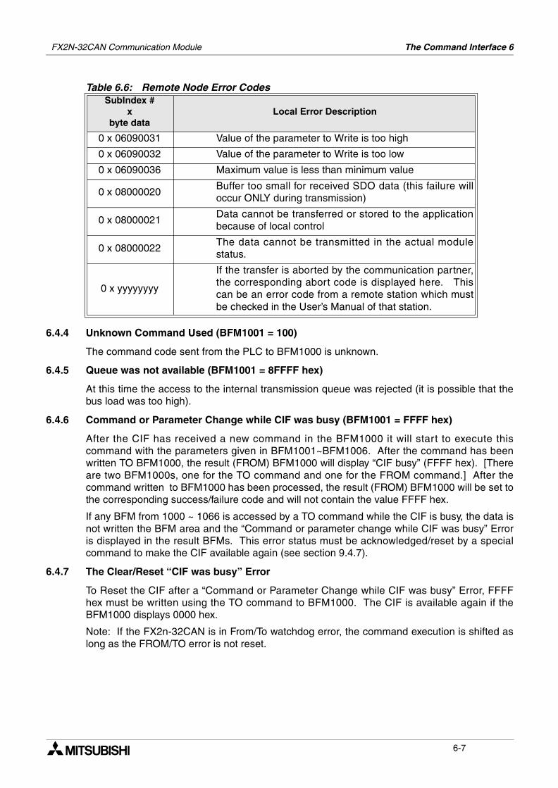
6.4.4 Unknown Command Used (BFM1001 = 100)
The command code sent from the PLC to BFM1000 is unknown.
6.4.5 Queue was not available (BFM1001 = 8FFFF hex)
At this time the access to the internal transmission queue was rejected (it is possible that thebus load was too high).
6.4.6 Command or Parameter Change while CIF was busy (BFM1001 = FFFF hex)
After the CIF has received a new command in the BFM1000 it will start to execute thiscommand with the parameters given in BFM1001~BFM1006. After the command has beenwritten TO BFM1000, the result (FROM) BFM1000 will display “CIF busy” (FFFF hex). [Thereare two BFM1000s, one for the TO command and one for the FROM command.] After thecommand written to BFM1000 has been processed, the result (FROM) BFM1000 will be set tothe corresponding success/failure code and will not contain the value FFFF hex.
If any BFM from 1000 ~ 1066 is accessed by a TO command while the CIF is busy, the data isnot written the BFM area and the “Command or parameter change while CIF was busy” Erroris displayed in the result BFMs. This error status must be acknowledged/reset by a specialcommand to make the CIF available again (see section 9.4.7).
6.4.7 The Clear/Reset “CIF was busy” Error
To Reset the CIF after a “Command or Parameter Change while CIF was busy” Error, FFFFhex must be written using the TO command to BFM1000. The CIF is available again if theBFM1000 displays 0000 hex.
Note: If the FX2n-32CAN is in From/To watchdog error, the command execution is shifted aslong as the FROM/TO error is not reset.
0 x 06090031 Value of the parameter to Write is too high
0 x 06090032 Value of the parameter to Write is too low
0 x 06090036 Maximum value is less than minimum value
0 x 08000020Buffer too small for received SDO data (this failure willoccur ONLY during transmission)
0 x 08000021Data cannot be transferred or stored to the applicationbecause of local control
0 x 08000022The data cannot be transmitted in the actual modulestatus.
0 x yyyyyyyy
If the transfer is aborted by the communication partner,the corresponding abort code is displayed here. Thiscan be an error code from a remote station which mustbe checked in the User’s Manual of that station.
Table 6.6: Remote Node Error CodesSubIndex #
x byte data
Local Error Description
6-7
FX2N-32CAN Communication Module The Command Interface 6
6.4.8 CIF Internal Error (BFM1001 = 200 hex)
This error code was implemented to handle possible errors which are not covered by thenormal error detection. If an error occurs which does not have a corresponding error code, aclassification value will be displayed in BFM1002 and the internal error data buffer is copied toBFM1003~1066.
If this error occurs, please contact your service representative.
6-8
The Mapping Modes 7FX2N-32CAN Communication Module
7. The Mapping Modes
In order to exhange data over the CANopen but the data channels between nodes must bedefined or “mapped”. The FX2N-32CAN module has been pre-configured to support threedefined mapping modes or can be configured completely to suit the user needs.
A network configuration tool is a powerful device for setting the parameter data for anymanufacturers node (including the FX2N-32CAN) and defining the data mapping connectionset. It is recommended to use a network configuration tool for large networks due to theconvenience, flexibility, and ease of use that the tools provide.
To build up a small network or for testing purposes, the module Command InterFace (CIF, seeChapter 9) supports three PDO mapping/binding commands designed for and supported bythe FX2N-32CAN module. By using these predefined Mapping configurations, the CAN objectID (COB-ID) number for data exchange for each node is clearly defined. For example an Rx-PDO (receive process data object) can be connected to a Tx-PDO (transmit process dataobject) of another node. These data will always be transmitted with the same COB-ID andevery node can distinguish relevant data by checking the COB-ID.
Note: It is strongly recommended to execute the Mapping Commands only in the pre-operational or stopped mode of the local and all related CANopen nodes.
Vocabulary Terms
Rx-PDO - Receive Process Data Objects are data read from other nodes via the CAN bus.
Tx-PDO - Transmit Process Data Objects are the data sent to other nodes via the CAN bus.
CIF - The Command Interface is the FX2N-32CAN tool used to perform actions such as to setparameters, execute commands, establish communication connections, access the CANopenObject Dictionary, and read error messages. It is located in BFM 1000~1066.
COB-ID - The CAN Object ID number is a unique identifying number to distinguish betweendifferent messages on the CANBus (e.g. PDO, SDO,NMT,SYNC, EMCY messages)
BFM - The Buffer Memory is the data storage memory location.
Mapping Mode 0 - Base Configuration where 4 Rx-PDOs and 4 Tx-PDOs are given BFMassignments for each FX2N-32CAN node according to the pre-defined connection set ofCANopen.
Mapping Mode A - Mitsubishi Electric defined configuration for the FX2N-32CAN module thatdefines the relationship between up to eight FX2N-32CAN nodes, the node BFMs, and the Rx-PDOs and Tx-PDOs. This mode is very convenient if every node is an FX2N-32CAN module.
Mapping Mode B - Configuration mode that allows specific Rx-PDOs and Tx-PDOs to bematched on a node by node basis.
For more information on the CANopen specifications please see the Can-in-Automationwebsite at www.can-cia.de.
7-1
FX2N-32CAN Communication Module The Mapping Modes 7
7.1 Factory Default Mapping/Mode 0 Mapping
The Factory Default Mapping conforms to CANopen specification DS-301 and contains onlythe first 2 Tx-PDOs and the first two Rx-PDOs. Please refer to the Tables in section 10.4 thatgive, repectively, the relationships between Tx-PDO number/COB-IDs/BFM# and the Rx-PDO/COB-IDs/BFM#.
By executing the Mode 0 mapping command shown below the number of automaticallyassigned Tx-PDOs becomes four instead of two. Four Rx-PDOs are also mappedautomatically.
The BFM 0-15 are distributed to Rx-PDOs 1-4 and Tx-PDOs 1-4 as shown in section 5.4.This setting is useful for a network that features many different types of node or as a base for anetwork mapping configured with the Mode B mapping command.
The PDOs from 5-30 (BFM16~19 and BFM100~199) are disabled in the default settings butfurther mapping of BFM16~19 and BFM100~199 can be accomplished using the Mode Bmapping technique.
7.2 Mode A Mapping
Setting up a CANopen network of only FX2N-32CAN nodes can be accomplished by simplyusing the Mode A Mapping configuration. Other types of CANopen modules can be added tothe Network but additional user inputs are necessary.
To establish communication between a FX2N-32CAN node and up to 7 other FX2N-32CANnodes it is only necessary to write the “set Mode A Mapping” command (8200 hex) to all theFX2N-32CAN modules via the local PLC. One of the nodes must be configured as the networkmanager. The network manager can be defined in the Network Configuration tool or by writingto the Object Dictionary using the CIF SDO write command.
When all the stations have executed the Mode A Mapping command, it is possible to exchange16 data words with every other FX2N-32CAN module*. Due to the data size, the number ofnodes in this mapping Mode is limited to 8 stations. If the node number is outside the range 1-8, BFM1000 will display the “node number mismatch” error message (82FF hex).
Table 7.1: Mode 0 Mapping Command
BFM# READ (FROM) WRITE (TO)
BFM1000 Mapping successfully established(8901) Command (8900 hex)
BFM1001 Unused Unused
: Unused Unused
BFM1066 Unused Unused
Table 7.2: Mode A Mapping Command
BFM# READ (FROM) WRITE (TO)
BFM1000
Mapping successfully established(8201 hex). Local node number MUST be in therange 1 - 8 (82FF hex)
Command (8200 hex)
BFM1001 Unused Unused
: Unused Unused
BFM1066 Unused Unused
7-2
FX2N-32CAN Communication Module The Mapping Modes 7
*Note: Nodes 1 - 7 can exchange 16 words of data with every other node but station number 8can send just 8 words of data to the other 7 stations. Node 8 can read the 16 words of datafrom all the other stations.
A closer look at the mapping shows that the Tx-PDO is dependent upon the node ID but themapping for the Rx-PDO is fixed to the default Tx-PDO COB-ID of the stations 1-8. Theadvantage is that the data location o the other nodes are the same for all FX2N-32CANmodules [eg. station #3 is always BFM112-127 (FROM)].
To include other types of CANopen nodes in the Mode A network, it is necessary to change theRx-PDO and communication parameters of these stations. This can be done by the Mode Bmapping commands, the SDO write access Command, or by a standard configuration tool.
Note: For Mode A Mapping th enode number of hte local FX2N-32CAN node must be in therange 1-8. If the node number is different, the result BFM1000 will display the “node numbermismatch” (82FF hex) error message.
7.3 Mode B Mapping
With Mode B Mapping, it is possible to build up a binding (a connection between two nodeaddresses) between all nodes connected to the FX2N-32CAN module. Also, the binding ofany CANopen node with any other CANopen node is supported. The Mode B mapping islimited to the binding of the PDOs which are already configured in the remote stations (nochange of the mapping between CANopen data and the remote node’s hardware) which will besuitable for most cases.
7.3.1 Prepare the PDO Mapping Table
The Mode B mapping command will modify or add to the current PDO mapping, therefore it isimportant to have a clearly defined mapping base before executing any Mode B commands.Executing the Mode B Mapping commands before creating a PDO mapping base may createerrors in the data transmission or module operation.
The PDO mapping base can be the “Mode 0” mapping or the “Mode A” mapping explained inprevious sections to prepare the default Rx-PDO and Tx-PDO formats as shown in section10.4. Another method to create (or reset) a Mapping base is to initialize the Mode B Mappingwith a special instruction at the beginning of the Mode B Mapping Command.
The purpose of the Mode B Mapping Commands is to bind a Tx-PDO from one CANopennode to a Rx-PDO of another node. This allows certain Buffer Memory information to betransfered/read in designated nodes around the CANopen network.
The Source parameter specifies the Node number and the specific Tx-PDO. The Destinationparameter specifies the Node number and the specific Rx-PDO that can read the data. Thecommand consists of four hexadecimal numbers, the two higher byte numbers specify thenode number and the two lower numbers specify the appropriate PDO number.
If it is necessary to change the remote node hardware mapping, this can be done by the SDOwrite access command or by a standard configuration tool.
The configuration with the Mode B mapping is controlled by a parameter set which is displayedin the table below.
7-3
FX2N-32CAN Communication Module The Mapping Modes 7
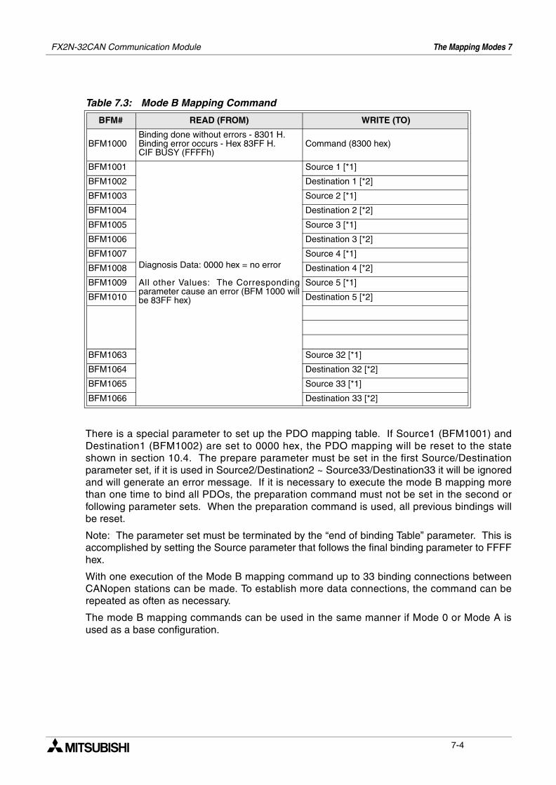
There is a special parameter to set up the PDO mapping table. If Source1 (BFM1001) andDestination1 (BFM1002) are set to 0000 hex, the PDO mapping will be reset to the stateshown in section 10.4. The prepare parameter must be set in the first Source/Destinationparameter set, if it is used in Source2/Destination2 ~ Source33/Destination33 it will be ignoredand will generate an error message. If it is necessary to execute the mode B mapping morethan one time to bind all PDOs, the preparation command must not be set in the second orfollowing parameter sets. When the preparation command is used, all previous bindings willbe reset.
Note: The parameter set must be terminated by the “end of binding Table” parameter. This isaccomplished by setting the Source parameter that follows the final binding parameter to FFFFhex.
With one execution of the Mode B mapping command up to 33 binding connections betweenCANopen stations can be made. To establish more data connections, the command can berepeated as often as necessary.
The mode B mapping commands can be used in the same manner if Mode 0 or Mode A isused as a base configuration.
Table 7.3: Mode B Mapping Command
BFM# READ (FROM) WRITE (TO)
BFM1000Binding done without errors - 8301 H.Binding error occurs - Hex 83FF H.CIF BUSY (FFFFh)
Command (8300 hex)
BFM1001
Diagnosis Data: 0000 hex = no error
All other Values: The Correspondingparameter cause an error (BFM 1000 willbe 83FF hex)
Source 1 [*1]
BFM1002 Destination 1 [*2]
BFM1003 Source 2 [*1]
BFM1004 Destination 2 [*2]
BFM1005 Source 3 [*1]
BFM1006 Destination 3 [*2]
BFM1007 Source 4 [*1]
BFM1008 Destination 4 [*2]
BFM1009 Source 5 [*1]
BFM1010 Destination 5 [*2]
BFM1063 Source 32 [*1]
BFM1064 Destination 32 [*2]
BFM1065 Source 33 [*1]
BFM1066 Destination 33 [*2]
7-4
FX2N-32CAN Communication Module The Mapping Modes 7
7.3.2 The Source Command
The task of the mapping command is to connect a data producer and a data consumer PDO tothe same message identifier. The Source Parameter specifies the producer to the datatelegram to bind.
The high byte of this parameter is the node ID number. The node ID range is 1~127. The localFX2N-32CAN module can be specified by the actual node number or by using a “0”.
The low byte specifies the PDO number. The FX2N-32CAN module will start a read access tothe object dictionary of the source node to read the COB-ID. This COB-ID is written in the nextstep to the Destination node’s PDO mapping table.
Ex. Source = 1009 hex. The node number is the high byte or node 10. The low bytedesignates Tx-PDO 09. This information will be bound to the node/Rx-PDO in the DestinationBFM that directly follows the Souce BFM.
Note: An error will be generated if the Destination BFM is not configured.
7.3.3 The Destination Parameter
This parameter defines the Destination for the corresponding Source parameter data. Thehigh byte of the BFM signifies the node number where the data is received and the low bytesignifies the Rx-PDO which is the final destination.
Ex. Destination = 0203 hex. The Source data will be bound to PDO #3 of Node 2.
The Destination node COB-ID is checked before the Source data is written to the mappingtable.
Note: An error message will be received if the Destination PDO was not written to thedestination PDO.
Note: The mode B mapping command cannot be used to change the mapping of the PDOsand/or the Hardware of the Remote modules. This type of network setup can be accomplishedby the SDO write access command or by a standard configuration tool.
7-5
FX2N-32CAN Communication Module The Mapping Modes 7
7.3.4 Assign Additional COB-IDs to the Local Node
By default every CANopen node can use four COB-IDs to transmit its data to other CANopenstations. All COB-IDs for Data transmission are by default reserved for the nodes 1~127. If itis necessary to transmit more than 4 PDOs (more than 16 words) from one node, this nodemust occupy COB-IDs of other (unused) stations. It is recommended to use the identifier ofhigher number stations for this purpose (127, 126, 125, etc). The lower the used COB-ID is,the higher is the priority of the messages. According to this, for highly important data it shouldbe avoided to assign the COB-ID of the Tx-PDO4/node 127 because all other Tx-PDO COB-IDs have a higher priority for transmission on the CANopen bus.
The Source parameter high byte defines the node which is by default the “owner” of hte COB-ID to occupy, the low byte defines the PDO number (Tx COB-ID = 0180 hex + node ID for Tx-PDO1/ 0280 hex + node ID for Tx-PDO2/ 0380 + node ID for Tx-PDO3/ 0480 hex + node ID forTx-PDO4).
To assign a COB-ID by the local station, the high byte number must be set to 80 hex.
The low byte tells the PDO number in the local station which shall use the occupied COB-ID.
Ex. Source = 7F01 hex, Destination = 8005 hex
The local FX2N-32CAN module will transfer the BFMs mapped to Tx-PDO 5 with the COB-IDof 1FF hex (by default this would be PDO 1 of node 127 = 180 +127).
Note: The local Tx-PDO numbers 1-4 are using the COB-IDs 180 hex + local node ID to 480hex + local node ID which are the standard COB-IDs. An attempt to assign a COB-ID to thefirst four PDOs will cause an error.
7.3.5 The End of the Parameter Table
If the last parameter is not located in BFM1065/1066, the paramter set must be terminated withSource = FFFF hex.
7-6
FX2N-32CAN Communication Module The Mapping Modes 7
7.4 PDO Mapping Table Overviews
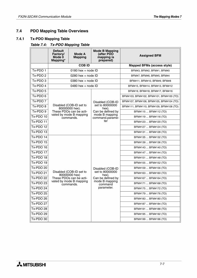
7.4.1 Tx-PDO Mapping Table
Table 7.4: Tx-PDO Mapping Table
Default Factory/Mode 0
Mapping*
Mode A Mapping
Mode B Mapping (after PDO mapping is prepared)
Assigned BFM
COB ID Mapped BFMs (access style)
Tx-PDO 1 0180 hex + node ID BFM#3, BFM#2, BFM#1, BFM#0
Tx-PDO 2 0280 hex + node ID BFM#7, BFM#6, BFM#5, BFM#4
Tx-PDO 3 0380 hex + node ID BFM#11, BFM#10, BFM#9, BFM#8
Tx-PDO 4 0480 hex + node ID BFM#15, BFM#14, BFM#13, BFM#12
Tx-PDO 5
Disabled (COB-ID set to 80000000 hex).
These PDOs can be acti-vated by mode B mapping
commands.
Disabled (COB-ID set to 80000000
hex).Can be defined by mode B mapping
command.parame-ter
BFM#19, BFM#18, BFM#17, BFM#16
Tx-PDO 6 BFM#103, BFM#102, BFM#101, BFM#100 (TO)
Tx-PDO 7 BFM#107, BFM#106, BFM#105, BFM#104 (TO)
Tx-PDO 8 BFM#111, BFM#110, BFM#109, BFM#108 (TO)
Tx-PDO 9 BFM#115 ... BFM#112 (TO)
Tx-PDO 10 BFM#119 ... BFM#116 (TO)
Tx-PDO 11 BFM#123 ... BFM#120 (TO)
Tx-PDO 12 BFM#127 ... BFM#124 (TO)
Tx-PDO 13 BFM#131 ... BFM#128 (TO)
Tx-PDO 14
Disabled (COB-ID set to 80000000 hex)
These PDOs can be acti-vated by mode B mapping
commands.
Disabled (COB-ID set to 80000000
hex).Can be defined by mode B mapping
command parameter.
BFM#135 ... BFM#132 (TO)
Tx-PDO 15 BFM#139 ... BFM#136 (TO)
Tx-PDO 16 BFM#143 ... BFM#140 (TO)
Tx-PDO 17 BFM#147 ... BFM#144 (TO)
Tx-PDO 18 BFM#151 ... BFM#148 (TO)
Tx-PDO 19 BFM#155 ... BFM#152 (TO)
Tx-PDO 20 BFM#159 ... BFM#156 (TO)
Tx-PDO 21 BFM#163 ... BFM#160 (TO)
Tx-PDO 22 BFM#167 ... BFM#164 (TO)
Tx-PDO 23 BFM#171 ... BFM#168 (TO)
Tx-PDO 24 BFM#175 ... BFM#172 (TO)
Tx-PDO 25 BFM#179 ... BFM#176 (TO)
Tx-PDO 26 BFM#183 ... BFM#180 (TO)
Tx-PDO 27 BFM#187 ... BFM#184 (TO)
Tx-PDO 28 BFM#191 ... BFM#188 (TO)
Tx-PDO 29 BFM#195 ... BFM#192 (TO)
Tx-PDO 30 BFM#199 ... BFM#196 (TO)
7-7
FX2N-32CAN Communication Module The Mapping Modes 7
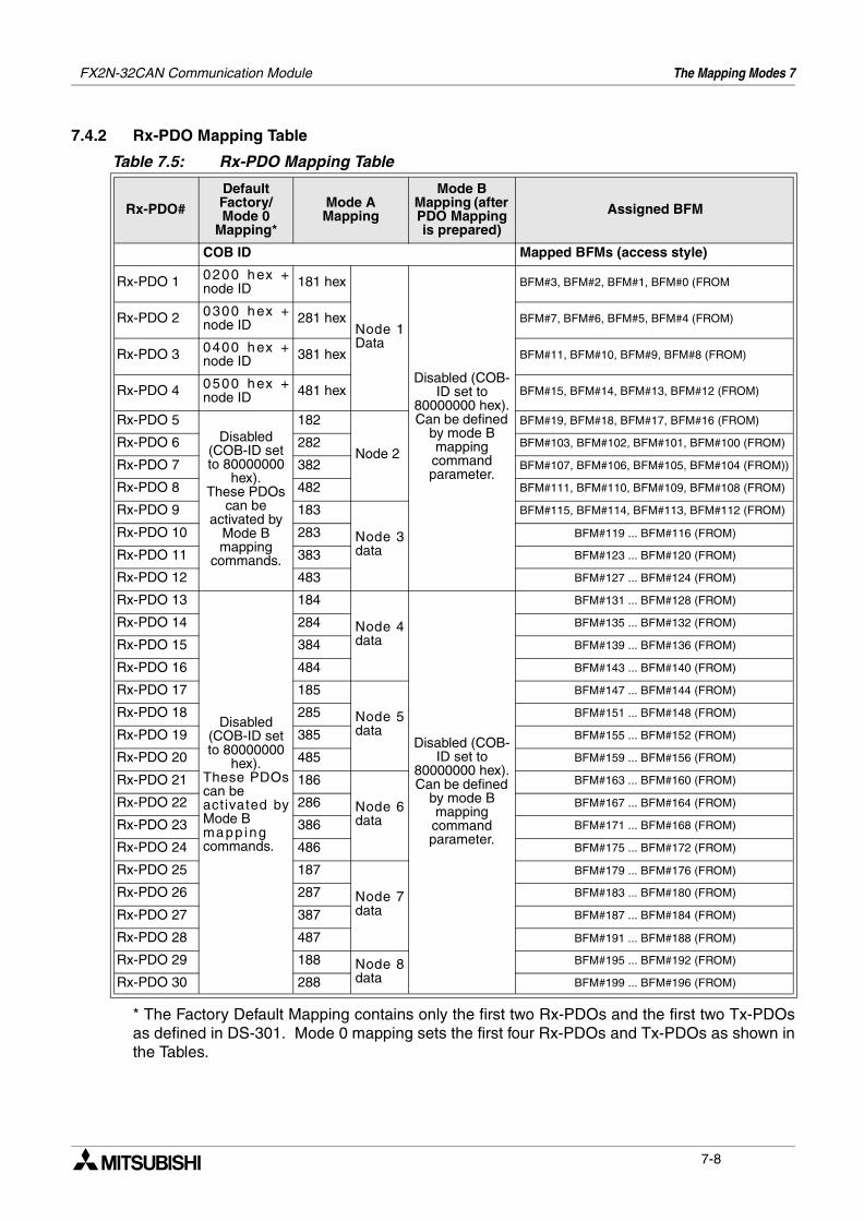
7.4.2 Rx-PDO Mapping Table
* The Factory Default Mapping contains only the first two Rx-PDOs and the first two Tx-PDOsas defined in DS-301. Mode 0 mapping sets the first four Rx-PDOs and Tx-PDOs as shown inthe Tables.
Table 7.5: Rx-PDO Mapping Table
Rx-PDO#
Default Factory/Mode 0
Mapping*
Mode A Mapping
Mode B Mapping (after PDO Mapping is prepared)
Assigned BFM
COB ID Mapped BFMs (access style)
Rx-PDO 1 0200 hex +node ID 181 hex
Node 1Data
Disabled (COB-ID set to
80000000 hex).Can be defined
by mode B mapping
command parameter.
BFM#3, BFM#2, BFM#1, BFM#0 (FROM
Rx-PDO 2 0300 hex +node ID 281 hex BFM#7, BFM#6, BFM#5, BFM#4 (FROM)
Rx-PDO 3 0400 hex +node ID 381 hex BFM#11, BFM#10, BFM#9, BFM#8 (FROM)
Rx-PDO 4 0500 hex +node ID 481 hex BFM#15, BFM#14, BFM#13, BFM#12 (FROM)
Rx-PDO 5Disabled
(COB-ID set to 80000000
hex). These PDOs
can beactivated by
Mode Bmapping
commands.
182
Node 2
BFM#19, BFM#18, BFM#17, BFM#16 (FROM)
Rx-PDO 6 282 BFM#103, BFM#102, BFM#101, BFM#100 (FROM)
Rx-PDO 7 382 BFM#107, BFM#106, BFM#105, BFM#104 (FROM))
Rx-PDO 8 482 BFM#111, BFM#110, BFM#109, BFM#108 (FROM)
Rx-PDO 9 183
Node 3data
BFM#115, BFM#114, BFM#113, BFM#112 (FROM)
Rx-PDO 10 283 BFM#119 ... BFM#116 (FROM)
Rx-PDO 11 383 BFM#123 ... BFM#120 (FROM)
Rx-PDO 12 483 BFM#127 ... BFM#124 (FROM)
Rx-PDO 13
Disabled (COB-ID set to 80000000
hex).These PDOscan be activated byMode B mapp ingcommands.
184
Node 4data
Disabled (COB-ID set to
80000000 hex).Can be defined
by mode B mapping
command parameter.
BFM#131 ... BFM#128 (FROM)
Rx-PDO 14 284 BFM#135 ... BFM#132 (FROM)
Rx-PDO 15 384 BFM#139 ... BFM#136 (FROM)
Rx-PDO 16 484 BFM#143 ... BFM#140 (FROM)
Rx-PDO 17 185
Node 5data
BFM#147 ... BFM#144 (FROM)
Rx-PDO 18 285 BFM#151 ... BFM#148 (FROM)
Rx-PDO 19 385 BFM#155 ... BFM#152 (FROM)
Rx-PDO 20 485 BFM#159 ... BFM#156 (FROM)
Rx-PDO 21 186
Node 6data
BFM#163 ... BFM#160 (FROM)
Rx-PDO 22 286 BFM#167 ... BFM#164 (FROM)
Rx-PDO 23 386 BFM#171 ... BFM#168 (FROM)
Rx-PDO 24 486 BFM#175 ... BFM#172 (FROM)
Rx-PDO 25 187
Node 7data
BFM#179 ... BFM#176 (FROM)
Rx-PDO 26 287 BFM#183 ... BFM#180 (FROM)
Rx-PDO 27 387 BFM#187 ... BFM#184 (FROM)
Rx-PDO 28 487 BFM#191 ... BFM#188 (FROM)
Rx-PDO 29 188 Node 8data
BFM#195 ... BFM#192 (FROM)
Rx-PDO 30 288 BFM#199 ... BFM#196 (FROM)
7-8
FX2N-32CAN Communication Module The Mapping Modes 7
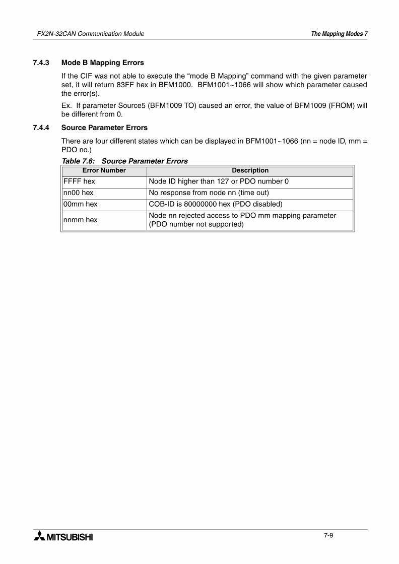
7.4.3 Mode B Mapping Errors
If the CIF was not able to execute the “mode B Mapping” command with the given parameterset, it will return 83FF hex in BFM1000. BFM1001~1066 will show which parameter causedthe error(s).
Ex. If parameter Source5 (BFM1009 TO) caused an error, the value of BFM1009 (FROM) willbe different from 0.
7.4.4 Source Parameter Errors
There are four different states which can be displayed in BFM1001~1066 (nn = node ID, mm =PDO no.)
Table 7.6: Source Parameter ErrorsError Number Description
FFFF hex Node ID higher than 127 or PDO number 0
nn00 hex No response from node nn (time out)
00mm hex COB-ID is 80000000 hex (PDO disabled)
nnmm hexNode nn rejected access to PDO mm mapping parameter (PDO number not supported)
7-9
FX2N-32CAN Communication Module The Mapping Modes 7
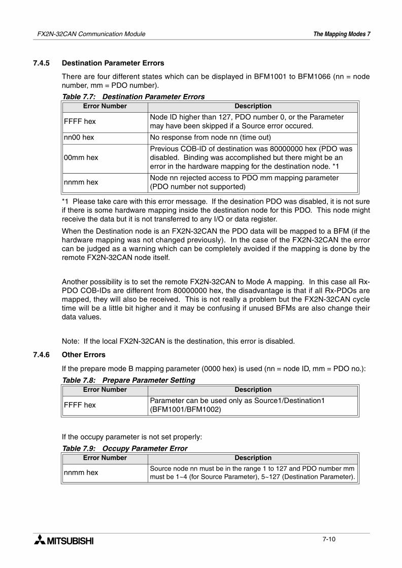
7.4.5 Destination Parameter Errors
There are four different states which can be displayed in BFM1001 to BFM1066 (nn = nodenumber, mm = PDO number).
*1 Please take care with this error message. If the desination PDO was disabled, it is not sureif there is some hardware mapping inside the destination node for this PDO. This node mightreceive the data but it is not transferred to any I/O or data register.
When the Destination node is an FX2N-32CAN the PDO data will be mapped to a BFM (if thehardware mapping was not changed previously). In the case of the FX2N-32CAN the errorcan be judged as a warning which can be completely avoided if the mapping is done by theremote FX2N-32CAN node itself.
Another possibility is to set the remote FX2N-32CAN to Mode A mapping. In this case all Rx-PDO COB-IDs are different from 80000000 hex, the disadvantage is that if all Rx-PDOs aremapped, they will also be received. This is not really a problem but the FX2N-32CAN cycletime will be a little bit higher and it may be confusing if unused BFMs are also change theirdata values.
Note: If the local FX2N-32CAN is the destination, this error is disabled.
7.4.6 Other Errors
If the prepare mode B mapping parameter (0000 hex) is used (nn = node ID, mm = PDO no.):
If the occupy parameter is not set properly:
Table 7.7: Destination Parameter ErrorsError Number Description
FFFF hexNode ID higher than 127, PDO number 0, or the Parameter may have been skipped if a Source error occured.
nn00 hex No response from node nn (time out)
00mm hex Previous COB-ID of destination was 80000000 hex (PDO was disabled. Binding was accomplished but there might be an error in the hardware mapping for the destination node. *1
nnmm hexNode nn rejected access to PDO mm mapping parameter (PDO number not supported)
Table 7.8: Prepare Parameter SettingError Number Description
FFFF hexParameter can be used only as Source1/Destination1 (BFM1001/BFM1002)
Table 7.9: Occupy Parameter ErrorError Number Description
nnmm hex Source node nn must be in the range 1 to 127 and PDO number mm must be 1~4 (for Source Parameter), 5~127 (Destination Parameter).
7-10
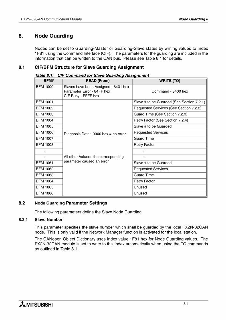
Node Guarding 8FX2N-32CAN Communication Module
8. Node Guarding
Nodes can be set to Guarding-Master or Guarding-Slave status by writing values to Index1F81 using the Command Interface (CIF). The parameters for the guarding are included in theinformation that can be written to the CAN bus. Please see Table 8.1 for details.
8.1 CIF/BFM Structure for Slave Guarding Assignment
8.2 Node Guarding Parameter Settings
The following parameters define the Slave Node Guarding.
8.2.1 Slave Number
This parameter specifies the slave number which shall be guarded by the local FX2N-32CANnode. This is only valid if the Network Manager function is activated for the local station.
The CANopen Object Dictionary uses Index value 1F81 hex for Node Guarding values. TheFX2N-32CAN module is set to write to this index automatically when using the TO commandsas outlined in Table 8.1.
Table 8.1: CIF Command for Slave Guarding AssignmentBFM# READ (From) WRITE (TO)
BFM 1000 Slaves have been Assigned - 8401 hexParameter Error - 84FF hexCIF Busy - FFFF hex
Command - 8400 hex
BFM 1001
Diagnosis Data: 0000 hex = no error
All other Values: the corresponding parameter caused an error.
Slave # to be Guarded (See Section 7.2.1)
BFM 1002 Requested Services (See Section 7.2.2)
BFM 1003 Guard Time (See Section 7.2.3)
BFM 1004 Retry Factor (See Section 7.2.4)
BFM 1005 Slave # to be Guarded
BFM 1006 Requested Services
BFM 1007 Guard Time
BFM 1008 Retry Factor
: :
: :
BFM 1061 Slave # to be Guarded
BFM 1062 Requested Services
BFM 1063 Guard Time
BFM 1064 Retry Factor
BFM 1065 Unused
BFM 1066 Unused
8-1
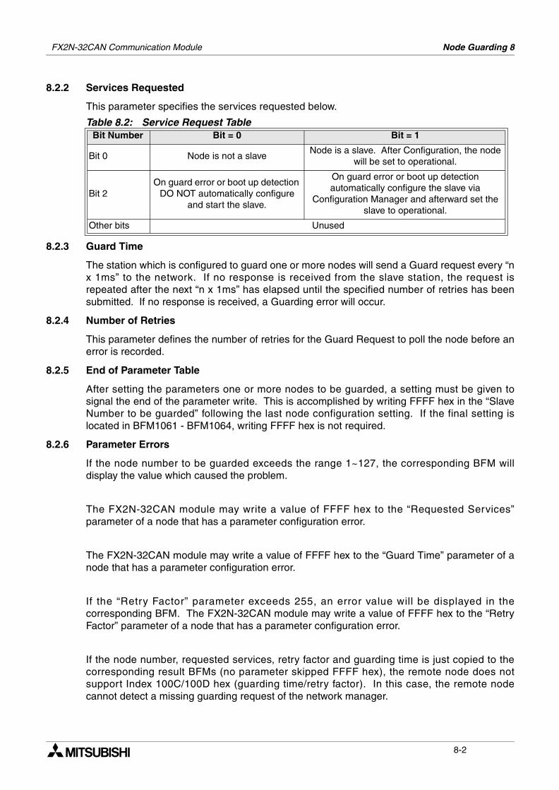
FX2N-32CAN Communication Module Node Guarding 8
8.2.2 Services Requested
This parameter specifies the services requested below.
8.2.3 Guard Time
The station which is configured to guard one or more nodes will send a Guard request every “nx 1ms” to the network. If no response is received from the slave station, the request isrepeated after the next “n x 1ms” has elapsed until the specified number of retries has beensubmitted. If no response is received, a Guarding error will occur.
8.2.4 Number of Retries
This parameter defines the number of retries for the Guard Request to poll the node before anerror is recorded.
8.2.5 End of Parameter Table
After setting the parameters one or more nodes to be guarded, a setting must be given tosignal the end of the parameter write. This is accomplished by writing FFFF hex in the “SlaveNumber to be guarded” following the last node configuration setting. If the final setting islocated in BFM1061 - BFM1064, writing FFFF hex is not required.
8.2.6 Parameter Errors
If the node number to be guarded exceeds the range 1~127, the corresponding BFM willdisplay the value which caused the problem.
The FX2N-32CAN module may write a value of FFFF hex to the “Requested Services”parameter of a node that has a parameter configuration error.
The FX2N-32CAN module may write a value of FFFF hex to the “Guard Time” parameter of anode that has a parameter configuration error.
If the “Retry Factor” parameter exceeds 255, an error value will be displayed in thecorresponding BFM. The FX2N-32CAN module may write a value of FFFF hex to the “RetryFactor” parameter of a node that has a parameter configuration error.
If the node number, requested services, retry factor and guarding time is just copied to thecorresponding result BFMs (no parameter skipped FFFF hex), the remote node does notsupport Index 100C/100D hex (guarding time/retry factor). In this case, the remote nodecannot detect a missing guarding request of the network manager.
Table 8.2: Service Request TableBit Number Bit = 0 Bit = 1
Bit 0 Node is not a slaveNode is a slave. After Configuration, the node
will be set to operational.
Bit 2On guard error or boot up detection
DO NOT automatically configure and start the slave.
On guard error or boot up detection automatically configure the slave via
Configuration Manager and afterward set the slave to operational.
Other bits Unused
8-2
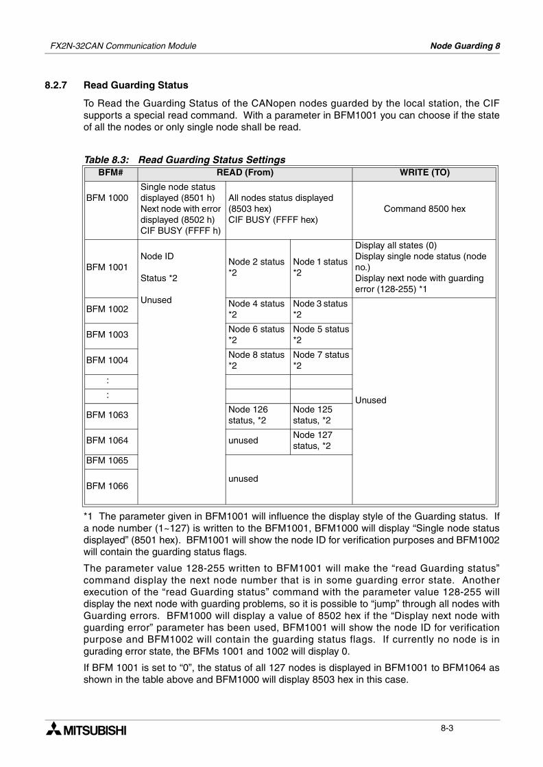
FX2N-32CAN Communication Module Node Guarding 8
8.2.7 Read Guarding Status
To Read the Guarding Status of the CANopen nodes guarded by the local station, the CIFsupports a special read command. With a parameter in BFM1001 you can choose if the stateof all the nodes or only single node shall be read.
*1 The parameter given in BFM1001 will influence the display style of the Guarding status. Ifa node number (1~127) is written to the BFM1001, BFM1000 will display “Single node statusdisplayed” (8501 hex). BFM1001 will show the node ID for verification purposes and BFM1002will contain the guarding status flags.
The parameter value 128-255 written to BFM1001 will make the “read Guarding status”command display the next node number that is in some guarding error state. Anotherexecution of the “read Guarding status” command with the parameter value 128-255 willdisplay the next node with guarding problems, so it is possible to “jump” through all nodes withGuarding errors. BFM1000 will display a value of 8502 hex if the “Display next node withguarding error” parameter has been used, BFM1001 will show the node ID for verificationpurpose and BFM1002 will contain the guarding status flags. If currently no node is ingurading error state, the BFMs 1001 and 1002 will display 0.
If BFM 1001 is set to “0”, the status of all 127 nodes is displayed in BFM1001 to BFM1064 asshown in the table above and BFM1000 will display 8503 hex in this case.
Table 8.3: Read Guarding Status SettingsBFM# READ (From) WRITE (TO)
BFM 1000Single node status displayed (8501 h)Next node with error displayed (8502 h)CIF BUSY (FFFF h)
All nodes status displayed (8503 hex)CIF BUSY (FFFF hex)
Command 8500 hex
BFM 1001Node ID
Status *2
Unused
Node 2 status *2
Node 1 status *2
Display all states (0)Display single node status (node no.)Display next node with guarding error (128-255) *1
BFM 1002Node 4 status *2
Node 3 status *2
Unused
BFM 1003Node 6 status*2
Node 5 status*2
BFM 1004Node 8 status*2
Node 7 status*2
:
:
BFM 1063Node 126 status, *2
Node 125 status, *2
BFM 1064 unusedNode 127status, *2
BFM 1065
unusedBFM 1066
8-3
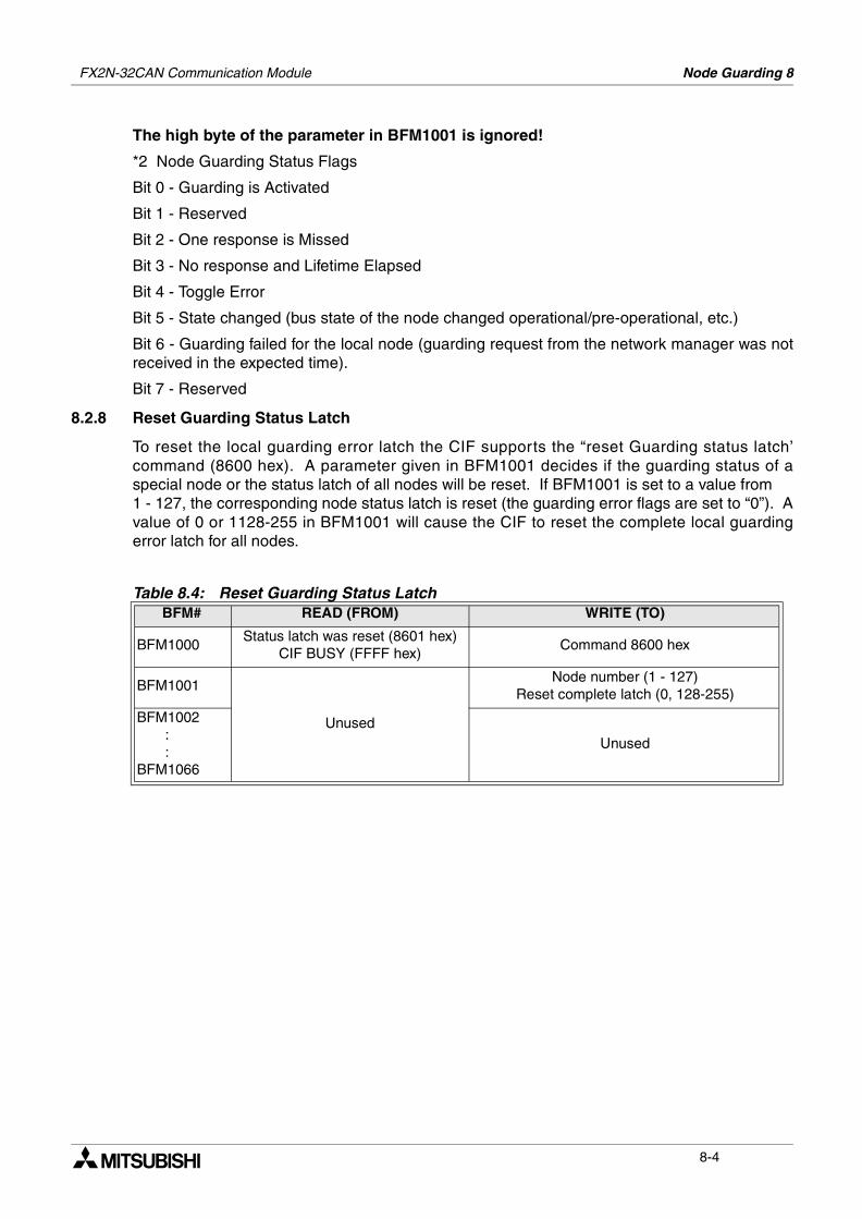
FX2N-32CAN Communication Module Node Guarding 8
The high byte of the parameter in BFM1001 is ignored!
*2 Node Guarding Status Flags
Bit 0 - Guarding is Activated
Bit 1 - Reserved
Bit 2 - One response is Missed
Bit 3 - No response and Lifetime Elapsed
Bit 4 - Toggle Error
Bit 5 - State changed (bus state of the node changed operational/pre-operational, etc.)
Bit 6 - Guarding failed for the local node (guarding request from the network manager was notreceived in the expected time).
Bit 7 - Reserved
8.2.8 Reset Guarding Status Latch
To reset the local guarding error latch the CIF supports the “reset Guarding status latch’command (8600 hex). A parameter given in BFM1001 decides if the guarding status of aspecial node or the status latch of all nodes will be reset. If BFM1001 is set to a value from 1 - 127, the corresponding node status latch is reset (the guarding error flags are set to “0”). Avalue of 0 or 1128-255 in BFM1001 will cause the CIF to reset the complete local guardingerror latch for all nodes.
Table 8.4: Reset Guarding Status LatchBFM# READ (FROM) WRITE (TO)
BFM1000Status latch was reset (8601 hex)
CIF BUSY (FFFF hex)Command 8600 hex
BFM1001
Unused
Node number (1 - 127)Reset complete latch (0, 128-255)
BFM1002 : :BFM1066
Unused
8-4
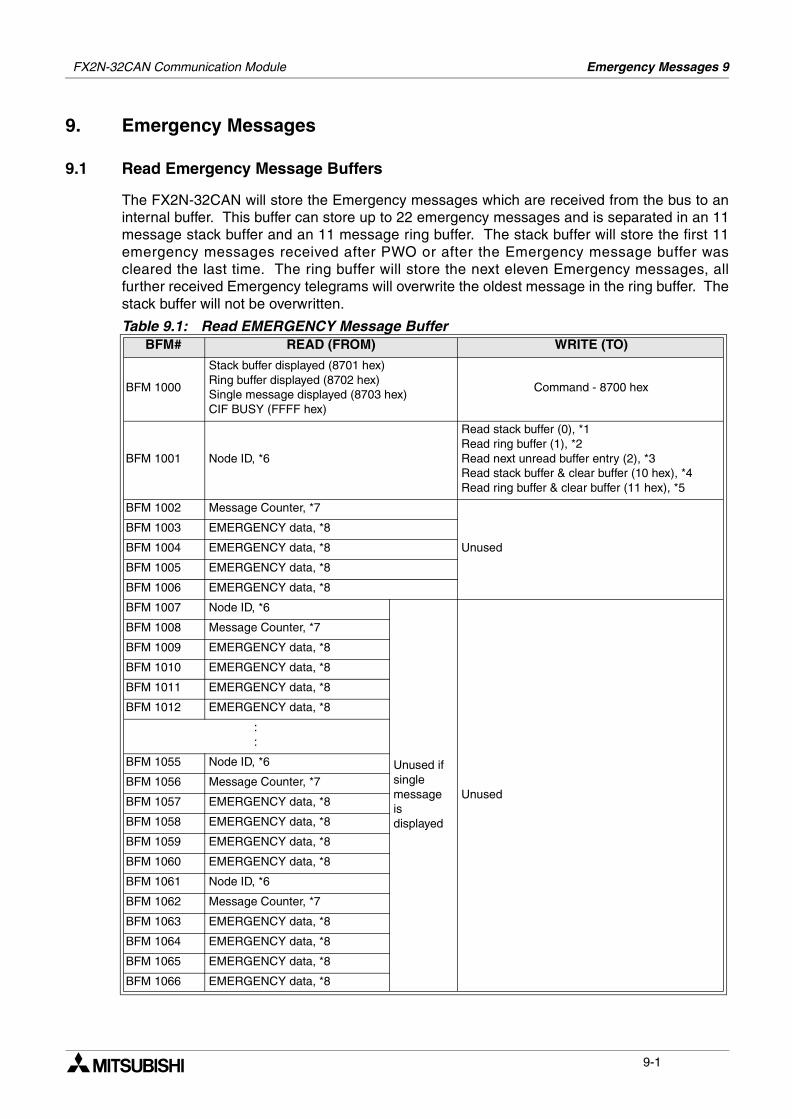
Emergency Messages 9FX2N-32CAN Communication Module
9. Emergency Messages
9.1 Read Emergency Message Buffers
The FX2N-32CAN will store the Emergency messages which are received from the bus to aninternal buffer. This buffer can store up to 22 emergency messages and is separated in an 11message stack buffer and an 11 message ring buffer. The stack buffer will store the first 11emergency messages received after PWO or after the Emergency message buffer wascleared the last time. The ring buffer will store the next eleven Emergency messages, allfurther received Emergency telegrams will overwrite the oldest message in the ring buffer. Thestack buffer will not be overwritten.
Table 9.1: Read EMERGENCY Message BufferBFM# READ (FROM) WRITE (TO)
BFM 1000
Stack buffer displayed (8701 hex)Ring buffer displayed (8702 hex)Single message displayed (8703 hex)CIF BUSY (FFFF hex)
Command - 8700 hex
BFM 1001 Node ID, *6
Read stack buffer (0), *1Read ring buffer (1), *2Read next unread buffer entry (2), *3Read stack buffer & clear buffer (10 hex), *4Read ring buffer & clear buffer (11 hex), *5
BFM 1002 Message Counter, *7
Unused
BFM 1003 EMERGENCY data, *8
BFM 1004 EMERGENCY data, *8
BFM 1005 EMERGENCY data, *8
BFM 1006 EMERGENCY data, *8
BFM 1007 Node ID, *6
Unused if single message is displayed
Unused
BFM 1008 Message Counter, *7
BFM 1009 EMERGENCY data, *8
BFM 1010 EMERGENCY data, *8
BFM 1011 EMERGENCY data, *8
BFM 1012 EMERGENCY data, *8
::
BFM 1055 Node ID, *6
BFM 1056 Message Counter, *7
BFM 1057 EMERGENCY data, *8
BFM 1058 EMERGENCY data, *8
BFM 1059 EMERGENCY data, *8
BFM 1060 EMERGENCY data, *8
BFM 1061 Node ID, *6
BFM 1062 Message Counter, *7
BFM 1063 EMERGENCY data, *8
BFM 1064 EMERGENCY data, *8
BFM 1065 EMERGENCY data, *8
BFM 1066 EMERGENCY data, *8
9-1
FX2N-32CAN Communication Module Emergency Messages 9
*1 - If the parameter 0 is set in BFM1001, the “read Emergency buffer” command will displaythe complete stack buffer in the BFM1001 to BFM1066. The stack buffer always contains thefirst eleven emergency messages which have been received since the PWO or since theemergency buffer has been cleared the last time. If the stack buffer is displayed the BFM1000will contain 8701 hex.
*2 - The parameter value 1 will cause the display of the whole content of the ring buffer. Theoldest message will be displayed in BFM1001 to BFM1066, the later messages in the higherBFMs. BFM1000 will display 8702 hex.
*3 - If the “read Emergency buffer” command is executed with the “read next unread bufferentry”, the CIF will display the next unread emergency message in BFM1001 to BFM1066.BFM1000 will display 8703 hex.
With every execution of the “read next unread buffer entry” command with this parameter, theCIF will show the next unread emergency message. After all unread messages have beenprocessed, the following executions will show “0” in BFM1001 to BFM1066 unless a newemergency message is received.
*4 - Basically this parameter will cause the same behavior as the “read stack buffer” parameterbut after the read access is finished, the internal emergency buffer is cleared (both stack andring buffers!!). The next received emergency message will be stored in the first cell of the stackbuffer.
*5 - Basically, this parameter will cause the same behavior as the “read ring buffer” parameterbut after the read access is finished, the internal emergency buffer is cleared (both stack andring buffers!!). The next received emergency message will be stored in the first cell of the stackbuffer.
*6 - The ID number of the node which sent the emergency message to the network isdisplayed.
*7 - The message counter shows a value from 1 to 255. This figure is a kind of running counterwhich is increased with every incoming emergency message until a value of 255 is reached.The counter will stay at this value as long as the buffer is not cleared and the module stayspowered On.
*8 - The next four BFMs contain the data of the emergency telegram. The first emergency databyte is located in the low byte of the first BFM, the second data byte in the high byte of the firstBFM.
9-2
FX2N-32CAN Communication Module Emergency Messages 9
9.2 Send an Emergency Message
This command can be used to send an emergency message by the PLC to the CANopennetwork.
*1 - Emergency data defined in DS301 revision 3.0.Write first emergency data byte to low byte of BFM1001, second emergency data byte to highbyte of BFM1001, third emergency data byte to low byte of BFM1002, and so on.
Unused emergency data bytes HAVE TO BE filled with 00 hex.
BFM# READ (FROM) WRITE (TO)
BFM 1000
No special return values, but the “Queue was not available” error may occur under high busload conditions.Also,CIF BUSY (FFFF hex)
Command - 000A hex
BFM 1001 Emergency Data byte 2 and 1, *1
BFM 1002 Emergency Data byte 4 and 3, *1
BFM 1003 Emergency Data byte 6 and 5, *1
BFM 1004 Emergency Data byte 8 and 7, *1
9-3
FX2N-32CAN Communication Module Emergency Messages 9
MEMO
9-4

Under no circumstances will Mitsubishi Electric be liable or responsible for anyconsequential damage that may arise as a result of the installation, use and/orprogramming of the products associated with this manual.All examples and diagrams shown in this manual are intended as an aid tounderstanding the text, not to guarantee operation. Mitsubishi Electric willaccept no responsibility for actual use of the product based on these illustrativeexamples.Owing to the very great variety of possible applications, users must satisfythemselves as to the suitability of each specific application.
HEADQUARTERS
EUROPEMITSUBISHI ELECTRIC EUROPE B.V.German BranchGothaer Straße 8D-40880 RatingenPhone: +49 (0)2102 / 486-0Fax: +49 (0)2102 / 486-1120
CZECH REPUBLICMITSUBISHI ELECTRIC EUROPE B.V.Czech BranchAvenir Business Park, Radlická 714/113aCZ-158 00 Praha 5Phone: +420 - 251 551 470Fax: +420 - 251-551-471
FRANCEMITSUBISHI ELECTRIC EUROPE B.V.French Branch25, Boulevard des BouvetsF-92741 Nanterre CedexPhone: +33 (0)1 / 55 68 55 68Fax: +33 (0)1 / 55 68 57 57
IRELANDMITSUBISHI ELECTRIC EUROPE B.V.Irish BranchWeIRPhFaxMIItaViaI-2PhFax: +39 039 / 60 53 312
POLANDMITSUBISHI ELECTRIC EUROPE B.V.Poland BranchKrakowska 50PL-32-083 BalicePhone: +48 (0)12 / 630 47 00Fax: +48 (0)12 / 630 47 01
SPAINMITSUBISHI ELECTRIC EUROPE B.V.Spanish BranchCarretera de Rubí 76-80E-08190 Sant Cugat del Vallés (Barcelona)Phone: 902 131121 // +34 935653131Fax: +34 935891579
UKMITSUBISHI ELECTRIC EUROPE B.V.UK BranchTravellers LaneUK-Hatfield, Herts. AL10 8XBPhone: +44 (0)1707 / 27 61 00Fax: +44 (0)1707 / 27 86 95
JAPANMITSUBISHI ELECTRIC CORPORATIONOffice Tower “Z” 14 F8-12,1 chome, Harumi Chuo-KuTokyo 104-6212Phone: +81 3 622 160 60Fax: +81 3 622 160 75
USAMITSUBISHI ELECTRIC AUTOMATION, Inc.500 Corporate Woods ParkwayVernon Hills, IL 60061Phone: +1 847 478 21 00Fax: +1 847 478 22 53
EUROPEAN REPRESENTATIVES
AUSTRIAGEVAWiener Straße 89AT-2500 BadenPhone: +43 (0)2252 / 85 55 20Fax: +43 (0)2252 / 488 60
BELARUSTEHNIKONOktyabrskaya 16/5, Off. 703-711BY-220030 MinskPhone: +375 (0)17 / 210 46 26Fax: +375 (0)17 / 210 46 26
BELGIUMESCO DRIVES & AUTOMATIONCulliganlaan 3BE-1831 DiegemPhone: +32 (0)2 / 717 64 30Fax: +32 (0)2 / 717 64 31
BELGIUMKoning & Hartman b.v.Woluwelaan 31BE-1800 VilvoordePhone: +32 (0)2 / 257 02 40Fax: +32 (0)2 / 257 02 49
Phone: +359 (0)2 / 817 6004Fax: +359 (0)2 / 97 44 06 1
CROATIAINEA CR d.o.o.Losinjska 4 aHR-10000 ZagrebPhone: +385 (0)1 / 36 940 - 01/ -02/ -03Fax: +385 (0)1 / 36 940 - 03
CZECH REPUBLICAutoCont C.S. s.r.o.Technologická 374/6CZ-708 00 Ostrava-PustkovecPhone: +420 595 691 150Fax: +420 595 691 199
CZECH REPUBLICB:ELECTRIC, s.r.o.Mladoboleslavská 812CZ-197 00 Praha 19 - KbelyPhone: +420 286 850 848, +420 724 317 975Fax: +420 286 850 850
DENMARKBeijer Electronics A/SLykkegårdsvej 17DK-4000 RoskildePhone: +45 (0)46/ 75 76 66Fax: +45 (0)46 / 75 56 26
ESTONIABeijer Electronics Eesti OÜPärnu mnt.160iEE-11317 TallinnPhone: +372 (0)6 / 51 81 40Fax: +372 (0)6 / 51 81 49
FINLANDBeijer Electronics OYPeltoie 37FIN-28400 UlvilaPhone: +358 (0)207 / 463 540Fax: +358 (0)207 / 463 541
GREECEUTECO A.B.E.E.5, Mavrogenous Str.GR-18542 PiraeusPhone: +30 211 / 1206 900Fax: +30 211 / 1206 999
HUNGARYMELTRADE Kft.Fertő utca 14.HU-1107 BudapestPhone: +36 (0)1 / 431-9726Fax: +36 (0)1 / 431-9727
LATVIABeijer Electronics SIARitausmas iela 23LV-1058 RigaPhone: +371 (0)784 / 2280Fax: +371 (0)784 / 2281
LITHUANIABeijer Electronics UABSavanoriu Pr. 187LT-02300 VilniusPhone: +370 (0)5 / 232 3101Fax: +370 (0)5 / 232 2980
EUROPEAN REPRESENTATIVES
MALTAALFATRADE Ltd.99, Paola HillMalta- Paola PLA 1702Phone: +356 (0)21 / 697 816Fax: +356 (0)21 / 697 817
MOLDOVAINTEHSIS srlbld. Traian 23/1MD-2060 KishinevPhone: +373 (0)22 / 66 4242Fax: +373 (0)22 / 66 4280
NETHERLANDSHIFLEX AUTOM.TECHNIEK B.V.Wolweverstraat 22NL-2984 CD RidderkerkPhone: +31 (0)180 – 46 60 04Fax: +31 (0)180 – 44 23 55
NETHERLANDSKoning & Hartman b.v.Haarlerbergweg 21-23NL-1101 CH AmsterdamPhone: +31 (0)20 / 587 76 00Fax: +31 (0)20 / 587 76 05
NORWAY
ROMANIA
Phone: +40 (0)21 / 430 40 06Fax: +40 (0)21 / 430 40 02
SERBIACraft Con. & Engineering d.o.o.Bulevar Svetog Cara Konstantina 80-86SER-18106 NisPhone: +381 (0)18 / 292-24-4/5Fax: +381 (0)18 / 292-24-4/5
SERBIAINEA SR d.o.o.Izletnicka 10SER-113000 SmederevoPhone: +381 (0)26 / 617 163Fax: +381 (0)26 / 617 163
SLOVAKIAAutoCont Control s.r.o.Radlinského 47SK-02601 Dolny KubinPhone: +421 (0)43 / 5868210Fax: +421 (0)43 / 5868210
SLOVAKIACS MTrade Slovensko, s.r.o.Vajanskeho 58SK-92101 PiestanyPhone: +421 (0)33 / 7742 760Fax: +421 (0)33 / 7735 144
SLOVENIAINEA d.o.o.Stegne 11SI-1000 LjubljanaPhone: +386 (0)1 / 513 8100Fax: +386 (0)1 / 513 8170
SWEDENBeijer Electronics ABBox 426SE-20124 MalmöPhone: +46 (0)40 / 35 86 00Fax: +46 (0)40 / 93 23 01
SWITZERLANDOmni Ray AGIm Schörli 5CH-8600 DübendorfPhone: +41 (0)44 / 802 28 80Fax: +41 (0)44 / 802 28 28
TURKEYGTSBayraktar Bulvari Nutuk Sok. No:5TR-34775 Yukarı Dudullu-Ümraniye-İSTANBULPhone: +90 (0)216 526 39 90Fax: +90 (0)216 526 3995
UKRAINECSC Automation Ltd.4-B, M. Raskovoyi St.UA-02660 KievPhone: +380 (0)44 / 494 33 55Fax: +380 (0)44 / 494-33-66
EURASIAN REPRESENTATIVES
KAZAKHSTANKazpromautomatics Ltd.Mustafina Str. 7/2KAZ-470046 KaragandaPhone: +7 7212 / 50 11 50Fax: +7 7212 / 50 11 50
MIDDLE EAST REPRESENTATIVES
ISRAELTEXEL ELECTRONICS Ltd.2 Ha´umanut, P.O.B. 6272IL-42160 NetanyaPhone: +972 (0)9 / 863 39 80Fax: +972 (0)9 / 885 24 30
LEBANONCEG INTERNATIONALCebaco Center/Block A Autostrade DORALebanon - BeirutPhone: +961 (0)1 / 240 430Fax: +961 (0)1 / 240 438
AFRICAN REPRESENTATIVE
SOUTH AFRICACBI Ltd.Private Bag 2016ZA-1600 IsandoPhone: + 27 (0)11 / 977 0770Fax: + 27 (0)11 / 977 0761
MITSUBISHI ELECTRIC
Mitsubishi Electric Europe B.V. /// FA - European Business Group /// Gothaer Straße 8 /// D-40Tel.: +49(0)2102-4860 /// Fax: +49(0)2102-4861120 /// [email protected] /// www.m
stgate Business Park, BallymountL-Dublin 24one: +353 (0)1 4198800: +353 (0)1 4198890
BOSNIA AND HERZEGOVINAINEA BH d.o.o.Aleja Lipa 56BA-71000 SarajevoPhone: +387 (0)33 / 921 164
Beijer Electronics ASPostboks 487NO-3002 DrammenPhone: +47 (0)32 / 24 30 00
ITALYTSUBISHI ELECTRIC EUROPE B.V.lian Branchle Colleoni 70041 Agrate Brianza (MB)one: +39 039 / 60 53 1
Fax: +387 (0)33/ 524 539BULGARIAAKHNATON
4 Andrej Ljapchev Blvd. Pb 21BG-1756 Sofia
Fax: +47 (0)32 / 84 85 77Sirius Trading & Services srlAleea Lacul Morii Nr. 3RO-060841 Bucuresti, Sector 6
880 Ratingen /// Germanyitsubishi-automation.com