Embed Size (px)
Citation preview

UG286: ClockBuilderPro™ FieldProgrammer Kit
This document describes how to use the ClockBuilder FieldProgrammer Kit (“CBPROG-DONGLE”) with ClockBuilder Pro™
(“CBPro”) to support four programming models.Refer to the text and table below for supported uses:
1. In-socket Firmware / NVM Programming• Firmware programming of a Si5383/84 device. Skyworks provides a 56-pin
socket adapter board for this purpose.• NVM programming of “base” devices (e.g., Si5341A-A-GM), or any other fac-
tory “pre-programmed” device (e.g., Si5341A-A12345-GM) which has unusedNVM banks. Skyworks provides 32-pin, 40-pin, 44-pin, 48-pin, and 64-pin QFNsocket adapter boards for this purpose.
2. In-system Firmware / NVM Programming• Firmware programming of a Si5383/84 devices already mounted on a system
PCB. Users are encouraged to include a standard 10-pin header on their PCBto allow the Si538x/4x/7x/9x Field Programmer board and ribbon cable to easilyconnect to the USB to SPI/I2C adapter.
• NVM programming of Si538x/4x/7x/9x devices already mounted on a systemPCB. Users are encouraged to include a standard 10-pin header on their PCBto allow the Si538x/4x/7x/9x Field Programmer board and ribbon cable to easilyconnect to the USB to SPI/I2C adapter.
3. In-system Volatile Register Programming• Devices mounted on a PCB (e.g., use the Design Dashboard and EVB GUIs
to inspect status registers, make volatile configuration updates, debug systemfirmware, etc.).
4. In-socket Volatile Register Programming• Devices mounted in the socket (e.g., use the Design Dashboard and EVB GUIs
to inspect status registers, make volatile configuration updates, debug systemfirmware, etc.).
KEY POINTS
• Shows and provides a brief explanation ofthe Field Programmer kit contents
• Points users to CBPro download andinstallation instructions
• Explains hardware configuration• Describes the four programming models to
use with the CBPROG-DONGLE• Includes CBPROG-DONGLE and socket
board schematics• Offers bill of materials• Includes troubleshooting appendix for
common issues
Table .1. Supported Programming Models
Location of TargetDevice
Software Utility andProgramming Model Supported
NVM Burn Tool EVB GUI / Dashboard
In-socket Yes (1) Yes (4)
In-system Yes (2) Yes (3)
Skyworks Solutions, Inc. • Phone [781] 376-3000 • Fax [781] 376-3100 • [email protected] • www.skyworksinc.com1 Rev. 1.3 • Skyworks Proprietary Information • Products and Product Information are Subject to Change Without Notice • January 14, 2022 1

1. Kit Contents
Shown below is a diagram of how the various components in the Field Programmer kit are connected to one of the QFN socket adapterboards, or to a PCB for in-system programming.
Figure 1.1. Example Hardware Configuration (Using QFN Socket Board or Customer PCB)
Figure 1.2 CBPROG-DONGLE Kit Contents on page 2 shows the kit contents for the CBPROG-DONGLE kit. Note in the figure onthe following page that the 32-pin, 40-pin, 44-pin, 48-pin, and 64-pin sockets are available separately as part numbers Si5332-32SKT-DK, Si5332-40SKT-DK, Si538x4x-44SKT-DK, Si5332-48SKT-DK, Si538x4x-56SKT-DK, Si538x4x-64SKT-DK, respectively. Note theSi5372/71/92/94 44-pin devices work with Si538x4x-44SKT-DK and the Si5395 works with the Si538x4x-64SKT-DK sockets. The ClockBuilder Pro Field Programmer resources including schematics, layout files, and BOM can be found at https://www.skyworksinc.com/en/products/timing/evaluation-kits/general/clockbuilder-pro-field-programmer. Note that the sockets are sold as separate kits.
Figure 1.2. CBPROG-DONGLE Kit Contents
UG286: ClockBuilderPro™ Field Programmer Kit • Kit Contents
Skyworks Solutions, Inc. • Phone [781] 376-3000 • Fax [781] 376-3100 • [email protected] • www.skyworksinc.com2 Rev. 1.3 • Skyworks Proprietary Information • Products and Product Information are Subject to Change Without Notice • January 14, 2022 2

Figure 1.3. Si5332-32SKT-DK, Si5332-40SKT-DK, Si538x4x-44SKT-DK, Si5332-48SKT-DK, Si538x4x-56SKT-DK,Si538x4x-64SKT-DK Sockets Sold Separately
UG286: ClockBuilderPro™ Field Programmer Kit • Kit Contents
Skyworks Solutions, Inc. • Phone [781] 376-3000 • Fax [781] 376-3100 • [email protected] • www.skyworksinc.com3 Rev. 1.3 • Skyworks Proprietary Information • Products and Product Information are Subject to Change Without Notice • January 14, 2022 3

2. Software Download and Installation
To install the CBPro software on any Windows 7 (or above) PC, go to https://www.skyworksinc.com/en/products/timing/evaluation-kits/general/clockbuilder-pro-field-programmer and download the ClockBuilder Pro Software (CBPro) installation file to install the softwareon your host PC.
UG286: ClockBuilderPro™ Field Programmer Kit • Software Download and Installation
Skyworks Solutions, Inc. • Phone [781] 376-3000 • Fax [781] 376-3100 • [email protected] • www.skyworksinc.com4 Rev. 1.3 • Skyworks Proprietary Information • Products and Product Information are Subject to Change Without Notice • January 14, 2022 4

3. Hardware Configuration
The Field Programmer Dongle acts as an interface between the CBPro GUI and the target device (any supported Si5332, Si534x,Si537x, Si538x or Si539x IC). Connect the provided USB cable to your PC and the CBPROG-DONGLE. The CBPROG-DONGLE isthen connected to the target device using the provided cables or a programming socket, depending upon the four ways you may usethe programmer as detailed in Section 4. Ways You can Use the Programmer.
UG286: ClockBuilderPro™ Field Programmer Kit • Hardware Configuration
Skyworks Solutions, Inc. • Phone [781] 376-3000 • Fax [781] 376-3100 • [email protected] • www.skyworksinc.com5 Rev. 1.3 • Skyworks Proprietary Information • Products and Product Information are Subject to Change Without Notice • January 14, 2022 5

4. Ways You can Use the Programmer
The following four sections describe four ways you can use the CBPROG-DONGLE.
4.1 In-Socket Firmware / NVM Programming
This workflow describes the process of programming loose devices using the Si5332-32SKT, Si5332-40SKT, Si5332-48SKT,Si538X4X-44SKT, Si538X4X-56SKT, or Si538X4X-64SKT programming socket board. For nonfirmware-based solutions, this flow will“burn” a complete configuration from CBPro into available NVM in the device. Si534x-8x devices shipped from Skyworks have twoNVM banks available to program (“burn”). Si5332 devices have a flexible NVM space. CBPro manages available NVM and programs("burns") the available NVM when feasible. For Si5383/84 (firmware based) devices, this flow will flash a complete configuration fromCBPro in to the device.
UG286: ClockBuilderPro™ Field Programmer Kit • Ways You can Use the Programmer
Skyworks Solutions, Inc. • Phone [781] 376-3000 • Fax [781] 376-3100 • [email protected] • www.skyworksinc.com6 Rev. 1.3 • Skyworks Proprietary Information • Products and Product Information are Subject to Change Without Notice • January 14, 2022 6
The steps needed to program a device’s NVM are as follows:1. Assuming the CBPro software is installed, connect the CBPROG-DONGLE adapter with the USB cable to the PC on which CBPro
was installed. Use the USB extender cable (provided with the kit) if your host PC is located far from the CBPROG-DONGLE.
Figure 4.1. PC to CBPROG-DONGLE Connection
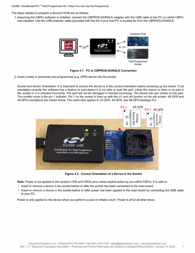
2. Insert a base or previously pre-programmed (e.g. OPN) device into the socket.
Socket and device Orientation: It is important to ensure the device is in the correct orientation before powering up the board. If notorientated correctly the software has a feature to auto-detect it is not able to read the part. Likely the reason is there is no part inthe socket or it is oriented incorrectly. The part will not be damaged if oriented incorrectly. The device has two circles on the part.The smaller circle is the pin 1 indicator. Pin 1 on the socket is lined up with the U1 and dot symbol on the silk screen. 64-QFN and44-QFN orientations are shown below. The same idea applies to 32-QFN, 40-QFN, and 48-QFN package ICs.
Si534xg-Rxxxxx-GM
YYWW
TTTTTT TW
64-QFNPin 1
x x
44-QFNPin 1
Si534xg-Rxxxxx-GM
YYWW
TTTTTT TW
Figure 4.2. Correct Orientation of a Device in the Socket
Note: Power is not applied to the socket’s VDD and VDDA pins unless explicit action by you within CBPro. It is safe to:• Insert or remove a device in the socket before or after the socket has been connected to the main board.• Insert or remove a device in the socket before or after power has been applied to the main board by connecting the USB cable
to your PC.
Power is only applied to the device when you perform a scan or initiate a burn. Power is off at all other times.
UG286: ClockBuilderPro™ Field Programmer Kit • Ways You can Use the Programmer
Skyworks Solutions, Inc. • Phone [781] 376-3000 • Fax [781] 376-3100 • [email protected] • www.skyworksinc.com7 Rev. 1.3 • Skyworks Proprietary Information • Products and Product Information are Subject to Change Without Notice • January 14, 2022 7

3. Connect the QFN Field Programmer Socket Board with the device into the CBPROG-DONGLE.
Field Programmer Main BoardField Programmer Socket Board
Figure 4.3. System from PC to Programming CBPROG-DONGLE Board to Field Programmer Socket Board
4. Start ClockBuilder Pro by locating the icon on your desktop or Windows Start Menu.
Figure 4.4. ClockBuilder Pro Icon
5. The ClockBuilder Pro Wizard main menu should now appear, as shown in the figure below. Select the “NVM Burn Tool” as shown.Do not select EVB GUI.
Figure 4.5. ClockBuilder Pro Wizard
UG286: ClockBuilderPro™ Field Programmer Kit • Ways You can Use the Programmer
Skyworks Solutions, Inc. • Phone [781] 376-3000 • Fax [781] 376-3100 • [email protected] • www.skyworksinc.com8 Rev. 1.3 • Skyworks Proprietary Information • Products and Product Information are Subject to Change Without Notice • January 14, 2022 8
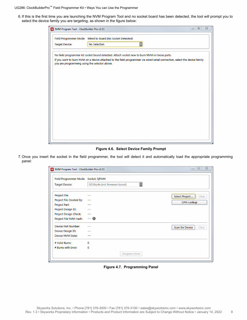
6. If this is the first time you are launching the NVM Program Tool and no socket board has been detected, the tool will prompt you toselect the device family you are targeting, as shown in the figure below:
Figure 4.6. Select Device Family Prompt
7. Once you insert the socket in the field programmer, the tool will detect it and automatically load the appropriate programmingpanel:
Figure 4.7. Programming Panel
UG286: ClockBuilderPro™ Field Programmer Kit • Ways You can Use the Programmer
Skyworks Solutions, Inc. • Phone [781] 376-3000 • Fax [781] 376-3100 • [email protected] • www.skyworksinc.com9 Rev. 1.3 • Skyworks Proprietary Information • Products and Product Information are Subject to Change Without Notice • January 14, 2022 9

4.1.1 Programming In-socket, Firmware Based Devices
Refer to Figure 4.8 Programming In-socket, Firmware Based Devices on page 10 below.1. Configure the I2C address and bus speed for the device.2. Select the firmware source.
• Configuration + Program from Project FileThe configuration defined by the specified project + the firmware release selected in the project file will be used to generate thefirmware image that will be flashed on the device. Note that different versions of CBPro may compute configuration registersdifferently for the same design goals as improvements are made to CBPro.
• Configuration + Program from Firmware FileFlash a stand-alone hex or binary firmware file to the device. You must have previously exported the file in CBPro, or the filewas sent to you by Skyworks. The firmware image contains both configuration and program data. This option is useful if youwant to ensure the same configuration register data is flashed to the device regardless of the CBPro version this tool is runningon. Firmware images can be created from the CBPro dashboard using the Export tool, selecting the stand-alone file option.
3. Click the “Select …” button and select the file to flash to the device.4. Click the “Scan for Device” button (optional): Click to detect device and report on part number, firmware version, and DESIGN_ID.
This is optional. You can click ‘Program NVM' without first scanning and all relevant pre-burn checks will be performed. Note adevice scan is also performed after the NVM burn has been completed, regardless of whether the burn completed successfully ornot.
5. Click the “Program NVM” button to flash device. In project file mode, CBPro will create a firmware image behind the scenes basedon the project file configuration, and then flash this on the device. The firmware download is verified via read back.
Figure 4.8. Programming In-socket, Firmware Based Devices
UG286: ClockBuilderPro™ Field Programmer Kit • Ways You can Use the Programmer
Skyworks Solutions, Inc. • Phone [781] 376-3000 • Fax [781] 376-3100 • [email protected] • www.skyworksinc.com10 Rev. 1.3 • Skyworks Proprietary Information • Products and Product Information are Subject to Change Without Notice • January 14, 2022 10

4.1.2 Programming In-socket, Non-Firmware Based Devices
Refer to Figure 4.9 Programming In-socket, Non-Firmware Based Devices on page 11 below.1. Click the “Select Project” button and select the project file.2. (Optional) Click the “Scan for Device” button to detect the device and report on part number, DESIGN_ID, and NVM bank state
(number of banks already burned, number available for burn). This is optional. You can click ‘Program NVM' without first scanningand all relevant pre-burn checks will be performed, such as verifying there is a bank available to burn. Note a device scan is alsoperformed after the NVM burn has been completed, regardless of whether the burn completed successfully or not.
3. Click the “Program NVM” button to start the programming flow:a. CBPro will compute the registers to program based on the design goals entered in the project file, using the latest algorithms
embedded in CBPro.b. CBPro will write volatile configuration registers corresponding to the project.c. CBPro will initiate a bank burn.d. CBPro will force an NVM reload on the device.e. CBPro will verify the bank burn by inspecting the bank pointer and read back the programmed registers.f. CBPro will rescan for the device and update burn count at the bottom of the window.
Figure 4.9. Programming In-socket, Non-Firmware Based Devices
4.1.3 In-Socket Programming Status
During the programming process and if the programming is successful, you should see the following windows.
Figure 4.10. In-Socket Programming Status
UG286: ClockBuilderPro™ Field Programmer Kit • Ways You can Use the Programmer
Skyworks Solutions, Inc. • Phone [781] 376-3000 • Fax [781] 376-3100 • [email protected] • www.skyworksinc.com11 Rev. 1.3 • Skyworks Proprietary Information • Products and Product Information are Subject to Change Without Notice • January 14, 2022 11

4.2 In-System Firmware / NVM Programming
This workflow describes the process of programming a device mounted on a PCB. For Si538x/4x/7x/9x (not firmware based) devices,this flow will “burn” a complete configuration from CBPro into one of the banks of NVM on the device, assuming an open NVM bankis available. Devices shipped from Skyworks always have two NVM banks available to program (“burn”). If you don’t know how manybanks are still open to burn on your target device, CBPro can detect and report the number of remaining NVM banks. For Si5383/84(firmware based) devices, this flow will flash a complete configuration from CBPro into the device.
The steps needed to program an “in-system” device’s NVM are as follows:1. Assuming the CBPro software is installed, connect the adapter (CBPROG-DONGLE) board with the USB cable to the PC on which
CBPro was installed.
Figure 4.11. PC to CBPROG-DONGLE Connection
UG286: ClockBuilderPro™ Field Programmer Kit • Ways You can Use the Programmer
Skyworks Solutions, Inc. • Phone [781] 376-3000 • Fax [781] 376-3100 • [email protected] • www.skyworksinc.com12 Rev. 1.3 • Skyworks Proprietary Information • Products and Product Information are Subject to Change Without Notice • January 14, 2022 12

2. Lookup and verify the host I/O mode (I2C or SPI), the I2C address, and the interface I/O voltage level compatibility of your host’sI/O voltage (for I2C or SPI) and the device.
The value set at the device register address of 0x0943 determines how the I/O supply voltages must be configured to communicatereliably with the CBPROG-DONGLE. You can look up your device host I/O voltage using the “OPN Lookup” option in the NVM Burntool, as shown in Figure 4.12 OPN Lookup Option on page 13.
Figure 4.12. OPN Lookup Option
If you have a custom OPN mounted on your board (a part number with a 5 digit code in the middle of the part number, such asSi5346B-A03260-GM), you should look up the host I/O setting (located at address of 0x0943) by selecting the OPN Lookup option.A browser will open and you will then enter in your custom OPN, as shown below.
a. Select “Clock or Buffer”.b. Enter in your full ordering part number (OPN). E.g., Si5346B-A03260-GM.c. Click the blue arrow to lookup your OPN to verify the host I/O voltage setting of your device.d. Click the addendum link.
Figure 4.13. OPN Lookup
UG286: ClockBuilderPro™ Field Programmer Kit • Ways You can Use the Programmer
Skyworks Solutions, Inc. • Phone [781] 376-3000 • Fax [781] 376-3100 • [email protected] • www.skyworksinc.com13 Rev. 1.3 • Skyworks Proprietary Information • Products and Product Information are Subject to Change Without Notice • January 14, 2022 13

3. When the utility displays the OPN’s files, click on Addendum to verify the I/O Power Supply setting of your device in the Data SheetAddendum.“VDD (Core)” indicates the I/O supply for the Si534x-8x-7x-9x I2C/SPI interface will operate from a 1.8 V supply.“VDDA (3.3 V)” indicates the I/O supply for the Si534x-8x-7x-9x I2C/SPI interface will operate from a 3.3 V supply. “VDDD”indicates the I/O supply for the Si5332 I2C interface.
Figure 4.14 Finding VDDA Value on page 14 shows an example data sheet addendum showing VDDA (3.3 V).
Figure 4.14. Finding VDDA Value
4. Connect/wire the pins of the CBPROG-DONGLE to your host system with the target device. Use the female-to-female ribbon cableto connect to your host board fitted with a standard 10-pin header. This assumes you included the 10-pin header on your PCBand followed the recommended pinout and connections to the target on your PCB. Note the pinout diagram and descriptions in thetable below.
Figure 4.15. Interface Pins on Header (Front View of CBPROG-DONGLE)
Table 4.1. Interface Pin Connections from CBPROG-DONGLE
Pin # Description Wire to Your PCB? I2C 4-wire SPI 3-wire SPI
9 A0_CSB
(applies only forSi534x-8x-7x-9
x device)
3- or 4-Wire SPI Can be used to set I2Caddress bit A0 high orlow. Routed to A0 devicepin on the programmingField Programmer SocketBoards.
Drives the chip select sig-nal during SPI transac-tions
Drives the chip select sig-nal during SPI transac-tions
10 VDD Never Supplies the Core VDDvoltage to the devicewhen using a program-ming Field ProgrammerSocket Board. Do not usethis pin for in-system pro-gramming.
Supplies the Core VDDvoltage to the devicewhen using a program-ming Field ProgrammerSocket Board. Do not usethis pin for in-system pro-gramming.
Supplies the core VDDvoltage to the devicewhen using a program-ming Field ProgrammerSocket Board. Do not usethis pin for in-system pro-gramming.
7 SDA_SDIO Always Serial data signal for I2Ctransactions.
Serial data out to devicefor 4-wire SPI transac-tions (MOSI).
Bidirectional Serial datafor 3-wire SPI transac-tions (SDIO).
8 I2C_SEL1
(applies only forSi534x-8x-7x-9
x device)
Never Used to set I2C_SEL sig-nal high to set the de-vice for I2C communica-tion. (Refer to specificpart pinout and the pro-gramming Field Program-mer Socket Board to de-termine whether to useI2C_SEL1 or I2C_SEL2)
Used to put I2C_SEL sig-nal low for SPI communi-cation. (Refer to specificpart pinout and the pro-gramming Field Program-mer Socket Board to de-termine whether to useI2C_SEL1 or I2C_SEL2)
Used to put I2C_SEL sig-nal low for SPI communi-cation. (Refer to specificpart pinout and the pro-gramming Field Program-mer Socket Board to de-termine whether to useI2C_SEL1 or I2C_SEL2)
UG286: ClockBuilderPro™ Field Programmer Kit • Ways You can Use the Programmer
Skyworks Solutions, Inc. • Phone [781] 376-3000 • Fax [781] 376-3100 • [email protected] • www.skyworksinc.com14 Rev. 1.3 • Skyworks Proprietary Information • Products and Product Information are Subject to Change Without Notice • January 14, 2022 14

Pin # Description Wire to Your PCB? I2C 4-wire SPI 3-wire SPI
5 A1_CSB
(applies only forSi534x-8x-7x-9
x device)
4-Wire SPI Only Can be used to set I2Caddress bit A1 high orlow. Routed to A1 devicepin on the programmingField Programmer SocketBoards.
Serial data from devicefor 4-wire SPI transac-tions (MISO).
Not used
6 I2C_SEL2
(applies only forSi534x-8x-7x-9
x device)
Never Used to set I2C_SEL sig-nal high to set the de-vice for I2C communica-tion. (Refer to specificpart pinout and the pro-gramming Field Program-mer Socket Board to de-termine whether to useI2C_SEL1 or I2C_SEL2)
Used to put I2C_SEL sig-nal low for SPI communi-cation. (Refer to specificpart pinout and the pro-gramming Field Program-mer Socket Board to de-termine whether to useI2C_SEL1 or I2C_SEL2)
Used to put I2C_SEL sig-nal low for SPI communi-cation. (Refer to specificpart pinout and the pro-gramming Field Program-mer Socket Board to de-termine whether to useI2C_SEL1 or I2C_SEL2)
3 SCLK Always Serial clock signal for I2Ctransactions.
Serial clock signal for SPItransactions.
Serial clock signal for SPItransactions.
4 VDDA_VDDS Never Supplies the VDDA andVDDS voltages to the de-vice when using a pro-gramming Field Program-mer Socket Board. Do notuse this pin for in-systemprogramming.
Supplies the VDDA andVDDS voltages to the de-vice when using a pro-gramming Field Program-mer Socket Board. Do notuse this pin for in-systemprogramming.
Supplies the VDDA andVDDS voltages to the de-vice when using a pro-gramming Field Program-mer Socket Board. Do notuse this pin for in-systemprogramming.
1 GND Always GND GND GND
2 ID Never The programming FieldProgrammer SocketBoards provide a voltageon this pin to identify theboard. For in-system pro-gramming, this pin shouldbe grounded or not con-nected to any signal.
The programming FieldProgrammer SocketBoards provide a voltageon this pin to identify theboard. For in-system pro-gramming, this pin shouldbe grounded or not con-nected to any signal.
The programming FieldProgrammer SocketBoards provide a voltageon this pin to identify theboard. For in-system pro-gramming, this pin shouldbe grounded or not con-nected to any signal.
UG286: ClockBuilderPro™ Field Programmer Kit • Ways You can Use the Programmer
Skyworks Solutions, Inc. • Phone [781] 376-3000 • Fax [781] 376-3100 • [email protected] • www.skyworksinc.com15 Rev. 1.3 • Skyworks Proprietary Information • Products and Product Information are Subject to Change Without Notice • January 14, 2022 15

4.2.1 I2C Hardware Configuration
For I2C Communication connecting to an external device board, the following pins should be used from the:
CBPROG-DONGLE• Pin 3: Serial Clock SCLK• Pin 7: Serial Data SDA• Pin 1: Ground
Si538x/4x/7x/9x DEVICE• A0/CS: Drive this pin high or low to set the I2C Address.• A1/SDO: Drive this pin high or low to set the I2C Address.• I2C_SEL: Drive this pin high to select I2C communication.
Figure 4.16. Example I2C Connection to External System Target Board Using Jumper Wires (Si5346-EVB)
When using SPI Communication with long wires as shown above it is advisable to use 6 Mb/s bus speed or less.
4.2.2 SPI 3-Wire Hardware Configuration
For 3-wire SPI communication, when connecting to an external device board, the following pins should be used from:
CBPROG-DONGLE• Pin 3: Serial Clock SCLK• Pin 7: Serial Data SDIO for Data In and Out• Pin 9: A0_CSB for Chip Select• Pin 1: Ground
Si538x/4x/7x/9x DEVICE• I2C_SEL: Drive this pin low to select SPI communication.
UG286: ClockBuilderPro™ Field Programmer Kit • Ways You can Use the Programmer
Skyworks Solutions, Inc. • Phone [781] 376-3000 • Fax [781] 376-3100 • [email protected] • www.skyworksinc.com16 Rev. 1.3 • Skyworks Proprietary Information • Products and Product Information are Subject to Change Without Notice • January 14, 2022 16

4.2.3 SPI 4-Wire Hardware Configuration
For 4-wire SPI communication, when connecting to an external device board, the following pins should be used from:
CBPROG-DONGLE• Pin 3: Serial Clock SCLK• Pin 7: Serial Data SDIO for Data In to device (MOSI)• Pin 5: A1_SDO for Data Out of device (MISO)• Pin 9: A0_CSB for Chip Select• Pin 1: Ground
Si538x/4x/7x/9x DEVICE• I2C_SEL: Drive this pin low to select SPI communication.
If this is the first time launching the NVM Program Tool, the tool will prompt user to select the device family they are targeting:
Figure 4.17. NVM Program Tool, Select Device Family
UG286: ClockBuilderPro™ Field Programmer Kit • Ways You can Use the Programmer
Skyworks Solutions, Inc. • Phone [781] 376-3000 • Fax [781] 376-3100 • [email protected] • www.skyworksinc.com17 Rev. 1.3 • Skyworks Proprietary Information • Products and Product Information are Subject to Change Without Notice • January 14, 2022 17

4.2.4 Programming In-system, Firmware Based Devices
Refer to Figure 4.18 Programming In-system, Firmware Based Devices on page 18 below.
After verifying the CBPro Dongle to device connections, execute the following steps. This example assumes a device is configured withan I2C address of 0x6F, and an I2C bus speed of 400 kHz.
1. Select “Si5383/43 (firmware based)” in the Target Device drop down.2. Click the Host Interface drop down:
a. Enter the I2C address of the device.b. Select the communication bus speed.
3. Select the firmware source.• Configuration + Program from Project File
The configuration defined by the specified project + the firmware release selected in the project file will be used to generate thefirmware image that will be flashed on the device. Note that different versions of CBPro may compute configuration registersdifferently for the same design goals as improvements are made to CBPro.
• Configuration + Program from Firmware FileFlash a stand-alone hex or binary firmware file to the device. You must have previously exported the file in CBPro, or the filewas sent to you by Skyworks. The firmware image contains both configuration and program data. This option is useful if youwant to ensure the same configuration register data is flashed to the device regardless of the CBPro version this tool is runningon. Firmware images can be created from the CBPro dashboard using the Export tool, selecting the stand-alone file option.
4. Click the “Select Project …” button and select the project file to be written to the device.5. (Optional) Click the “Scan for Device” button to detect device and report on part number, firmware version, and DESIGN_ID. This is
optional. You can click Program NVM' without first scanning and all relevant pre-program checks will be performed. Note a devicescan is also performed after the NVM programming has been completed, regardless of whether the programming completedsuccessfully or not.
6. Click the “Program NVM” button to flash device. In project file mode, CBPro will create a firmware image behind the scenes basedon the project file configuration, and then flash this on the device. The firmware download is verified via read back.
Figure 4.18. Programming In-system, Firmware Based Devices
UG286: ClockBuilderPro™ Field Programmer Kit • Ways You can Use the Programmer
Skyworks Solutions, Inc. • Phone [781] 376-3000 • Fax [781] 376-3100 • [email protected] • www.skyworksinc.com18 Rev. 1.3 • Skyworks Proprietary Information • Products and Product Information are Subject to Change Without Notice • January 14, 2022 18

4.2.5 Programming In-system, Non-firmware Based Devices
Refer to Figure 4.19 Programming In-system, Non-firmware Based Devices on page 19 below.
After verifying the CBPro Dongle to device connections, execute the following steps. This example assumes a device is configured withthe host I2C interface operating in 3.3 V I/O mode with an I2C address of 0x6F, and an I2C bus speed of 400 kHz.
1. Select “Si538x/4x/7x/9x (not firmware based) in the Target Device drop down.2. Click the Host Interface drop down: (Review: host I/O mode (I2C or SPI), the I2C address, and I/O voltage level to determine
these settings)a. Select communication protocol for the device.b. Select the I/O voltage for the devicec. For I2C, enter the address of the device.d. Select the communication bus speed.
3. Click the “Select Project …” button and select the project file to be written to the device.4. (Optional) Click the “Scan for Device” button to detect the device and report on part number, DESIGN_ID, and NVM bank state
(number of banks already burned, number available for burn). This is optional. You can click Program NVM' without first scanningand all relevant pre-programming checks will be performed, such as verifying there is a bank available to burn. Note a device scanis also performed after the NVM burn has been completed, regardless of whether the burn completed successfully or not.
5. Click the “Program NVM” button to start the programming flow:a. CBPro will compute the registers to program based on the design goals entered in the project file, using the latest algorithms
embedded in CBPro.b. CBPro will write volatile configuration registers corresponding to the project.c. CBPro will initiate a bank burn.d. CBPro will force an NVM reload on the device.e. CBPro will verify the bank burn by inspecting the bank pointer and read back the programmed registers.f. CBPro will rescan for the device and update burn count at the bottom of the window.
Figure 4.19. Programming In-system, Non-firmware Based Devices
UG286: ClockBuilderPro™ Field Programmer Kit • Ways You can Use the Programmer
Skyworks Solutions, Inc. • Phone [781] 376-3000 • Fax [781] 376-3100 • [email protected] • www.skyworksinc.com19 Rev. 1.3 • Skyworks Proprietary Information • Products and Product Information are Subject to Change Without Notice • January 14, 2022 19

4.2.6 Programming Status
During the programming process and if the programming is successful, you should see the following windows:
Figure 4.20. Programming Status
4.3 In-System Volatile Register Programming and Register Debug
This workflow allows users to use the full CBPro configuration Wizard and EVB GUI to make volatile changes to a device’s configura-tion and inspect the state of various status registers. There are two ways you can interact with your PCB-based device using the fieldprogrammer:• Use CBPro Design Dashboard to edit your device configuration, and write out changes directly to your device.• Launch the EVB GUI, to inspect registers.
All of the relevant CBPro features available when working with a Skyworks EVB will be available to you, with these exceptions:• There is no voltage regulator control or voltage/current readings of any kind.• You must configure the host interface settings so that CBPro can use the device correct communication scheme/wire out.• If you write out your design/project file, all registers configured via the “Host Interface” section of the wizard are written to the device
(these registers are skipped when writing a design to a Skyworks EVB).
4.3.1 Using the CBPro Design Dashboard
When you launch CBPro, instead of clicking the NVM Burn Tool, open your existing project file or a sample file to open the designdashboard window as shown in the figure below.
Figure 4.21. Open Design Project File, and see Field Programmer Detected
UG286: ClockBuilderPro™ Field Programmer Kit • Ways You can Use the Programmer
Skyworks Solutions, Inc. • Phone [781] 376-3000 • Fax [781] 376-3100 • [email protected] • www.skyworksinc.com20 Rev. 1.3 • Skyworks Proprietary Information • Products and Product Information are Subject to Change Without Notice • January 14, 2022 20

4.3.2 Overview of CBPro Configuration Wizard and the Field Programmer
When you open a ClockBuilder Pro project file, you are taken to the design dashboard. This is a gateway to perform activities againstyour design, including writing your project’s configuration to a device using the CBPro Dongle. For example, in the figure below, aSi5345 project has been opened and the CBPro Dongle has been detected, and no socket is present:
Figure 4.22. Overview of CBPro Configuration Wizard and the Field Programmer
With a click of the “Write Design to DUT” button, you can reconfigure the Si5345 in-system to test changes to your design. The “OpenEVB GUI” button can be used to launch the EVB GUI and peek/poke registers on the in-system device. See Section 4.3.4 Using theEVB GUI with In-system Devices to learn more.
UG286: ClockBuilderPro™ Field Programmer Kit • Ways You can Use the Programmer
Skyworks Solutions, Inc. • Phone [781] 376-3000 • Fax [781] 376-3100 • [email protected] • www.skyworksinc.com21 Rev. 1.3 • Skyworks Proprietary Information • Products and Product Information are Subject to Change Without Notice • January 14, 2022 21

4.3.2.1 Using the Dashboard with In-system Devices
If the CBPro Dongle is connected via USB and detected by CBPro, you will see will see a pulldown to configure the host interfacebetween the dongle and your PCB, as shown in the figure below. Refer to Section 4.2 In-System Firmware / NVM Programming forinformation to connect the CBPro Dongle to your hardware.
Figure 4.23. Field Programmer Detected
Click the interface pulldown to configure the communication interface, as shown in the figure below. For firmware based devices(e.g. Si5383), the I2C address and bus speed need to be configured. For non-firmware based devices (e.g. Si5340, Si5341), Thecommunication protocol and the I/O voltage need to be configured. If the communication protocol is I2C, the address and bus speed willneed to be configured as well.
Figure 4.24. Communication Interface Selection
Once configured, you can write out your design to the device by clicking the Write Design to DUT button:
Figure 4.25. Write Design to DUT
Or on any configuration page in the wizard:
Figure 4.26. Write to FP
UG286: ClockBuilderPro™ Field Programmer Kit • Ways You can Use the Programmer
Skyworks Solutions, Inc. • Phone [781] 376-3000 • Fax [781] 376-3100 • [email protected] • www.skyworksinc.com22 Rev. 1.3 • Skyworks Proprietary Information • Products and Product Information are Subject to Change Without Notice • January 14, 2022 22

When you initiate a project write to the DUT, CBPro will first try to verify the DUT is present via the communication interface youhave configured. This is normally accomplished by trying to read device identification register on the device, such as PN_BASE onSi538x/4x/7x/9x devices.
If it cannot read these registers, the DUT write will be aborted and you will see an error message like the example shown in the figurebelow:
Figure 4.27. Error Message
UG286: ClockBuilderPro™ Field Programmer Kit • Ways You can Use the Programmer
Skyworks Solutions, Inc. • Phone [781] 376-3000 • Fax [781] 376-3100 • [email protected] • www.skyworksinc.com23 Rev. 1.3 • Skyworks Proprietary Information • Products and Product Information are Subject to Change Without Notice • January 14, 2022 23

4.3.2.2 Using the CBPro Dashboard with In-socket Devices
In the design dashboard, you will see a pulldown to configure the host interface between the CBPro Dongle and the socket. Ifthe connected socket is not compatible with the selected CBPro project file, an error message will be displayed and the interfaceconfiguration pulldown will be disabled, as shown in the figure below.
Figure 4.28. Socket Compatibility
Click the interface pulldown, configure the interface, and click the slider power to turn on the socket power. For firmware based devices(e.g. Si5383), the I2C address and bus speed need to be configured. For non-firmware based devices (e.g. Si5340, Si5341), thecommunication protocol and the I/O voltage need to be configured. If the communication protocol is I2C, the address and bus speed willneed to be configured, as shown in the figure below.
Note: Manually powering up the socket is an optional step. If you click the “Write Design to DUT” button, CBPro will automaticallypower up the socket (and you will see it switch from Off to the On state). Socket power refers to VDD and VDDA power on the device.
Figure 4.29. Interface Settings
Once configured, you can write out your design to the device by clicking the Write Design to DUT button:
Figure 4.30. Write Design to DUT
Or on any configuration page in the wizard:
UG286: ClockBuilderPro™ Field Programmer Kit • Ways You can Use the Programmer
Skyworks Solutions, Inc. • Phone [781] 376-3000 • Fax [781] 376-3100 • [email protected] • www.skyworksinc.com24 Rev. 1.3 • Skyworks Proprietary Information • Products and Product Information are Subject to Change Without Notice • January 14, 2022 24

Figure 4.31. Write Design to FP
UG286: ClockBuilderPro™ Field Programmer Kit • Ways You can Use the Programmer
Skyworks Solutions, Inc. • Phone [781] 376-3000 • Fax [781] 376-3100 • [email protected] • www.skyworksinc.com25 Rev. 1.3 • Skyworks Proprietary Information • Products and Product Information are Subject to Change Without Notice • January 14, 2022 25

4.3.3 Launching the CBPro EVB GUI
From the CBPro Wizard screen, click the EVB GUI button to open the EVB GUI screen.
Figure 4.32. Open EVB GUI Screen
If this is the first time launching the EVB GUI and no socket board is detected, the tool will prompt user to select the device family theyare targeting:
Figure 4.33. Select Device Family Prompt
If a socket is connected, the family is auto selected based on the socket. The tool polls for socket state every 500 milliseconds and willdetect if a socket is present or has been changed.
UG286: ClockBuilderPro™ Field Programmer Kit • Ways You can Use the Programmer
Skyworks Solutions, Inc. • Phone [781] 376-3000 • Fax [781] 376-3100 • [email protected] • www.skyworksinc.com26 Rev. 1.3 • Skyworks Proprietary Information • Products and Product Information are Subject to Change Without Notice • January 14, 2022 26

Figure 4.34. Socket Detected, Auto-selected Family Prompt
UG286: ClockBuilderPro™ Field Programmer Kit • Ways You can Use the Programmer
Skyworks Solutions, Inc. • Phone [781] 376-3000 • Fax [781] 376-3100 • [email protected] • www.skyworksinc.com27 Rev. 1.3 • Skyworks Proprietary Information • Products and Product Information are Subject to Change Without Notice • January 14, 2022 27

4.3.4 Using the EVB GUI with In-system Devices
Connect the CBPro Dongle to the PCB mounted device. Refer to Section 4.2 In-System Firmware / NVM Programming for informationto connect the CBPro Dongle to your hardware. Click the Config button and click the Device Family pulldown to select either a firmwarebased device or a non-firmware based device. Then configure the communication protocol, bus speed and I/O voltage (non-firmwaredevices) for the device, as shown in the figure below.
Note: For firmware based devices the communication protocol available is I2C with a 3.3 V I/O voltage. For non-firmware baseddevices, there is a selection of SPI 4-wire, SPI 3-wire, or I2C and the I/O voltage must be selected.
Figure 4.35. Configuring an In-system Device
After the configuration is complete, click the Scan button. The Part Number and Design ID fields should update with the deviceinformation along with the Info tab fields, as shown in Figure 4.36 In-System Scan Prompt and DUT Register Editor Tab on page 29.Now the DUT Register Editor tab can be used to make volatile register value changes to the device and the Status Registers tab can beused to monitor the status of the device.
UG286: ClockBuilderPro™ Field Programmer Kit • Ways You can Use the Programmer
Skyworks Solutions, Inc. • Phone [781] 376-3000 • Fax [781] 376-3100 • [email protected] • www.skyworksinc.com28 Rev. 1.3 • Skyworks Proprietary Information • Products and Product Information are Subject to Change Without Notice • January 14, 2022 28

Figure 4.36. In-System Scan Prompt and DUT Register Editor Tab
UG286: ClockBuilderPro™ Field Programmer Kit • Ways You can Use the Programmer
Skyworks Solutions, Inc. • Phone [781] 376-3000 • Fax [781] 376-3100 • [email protected] • www.skyworksinc.com29 Rev. 1.3 • Skyworks Proprietary Information • Products and Product Information are Subject to Change Without Notice • January 14, 2022 29

4.3.5 Using the EVB GUI with In-socket Devices
CBPro will detect the connected socket when the EVB GUI is started. Click the Config button to configure the communication protocol,address (I2C), bus speed, and the I/O voltage (non-firmware based devices), as shown in the figure below.
Note: For firmware based devices the communication protocol available is I2C with a 3.3 volt I/O voltage. For non-firmware baseddevices, there is a selection of SPI 4-wire, SPI 3-wire, or I2C and the I/O voltage must be selected.
Figure 4.37. Configuring an In-socket Device
After the configuration is complete, click the Socket Power slider and the Scan button. The Part Number and Design ID fields shouldupdate with the device information along with the Info tab fields, as shown in Figure 4.38 In-Socket Scan Prompt and DUT RegisterEditor Tab on page 31. Now the DUT Register Editor tab can be used to make volatile register value changes to the device and theStatus Registers tab can be used to monitor the status of the device.
UG286: ClockBuilderPro™ Field Programmer Kit • Ways You can Use the Programmer
Skyworks Solutions, Inc. • Phone [781] 376-3000 • Fax [781] 376-3100 • [email protected] • www.skyworksinc.com30 Rev. 1.3 • Skyworks Proprietary Information • Products and Product Information are Subject to Change Without Notice • January 14, 2022 30

Figure 4.38. In-Socket Scan Prompt and DUT Register Editor Tab
UG286: ClockBuilderPro™ Field Programmer Kit • Ways You can Use the Programmer
Skyworks Solutions, Inc. • Phone [781] 376-3000 • Fax [781] 376-3100 • [email protected] • www.skyworksinc.com31 Rev. 1.3 • Skyworks Proprietary Information • Products and Product Information are Subject to Change Without Notice • January 14, 2022 31

5. CBPROG-DONGLE Schematic
Figure 5.1. CBPROG-DONGLE Schematic (1 of 3)
UG286: ClockBuilderPro™ Field Programmer Kit • CBPROG-DONGLE Schematic
Skyworks Solutions, Inc. • Phone [781] 376-3000 • Fax [781] 376-3100 • [email protected] • www.skyworksinc.com32 Rev. 1.3 • Skyworks Proprietary Information • Products and Product Information are Subject to Change Without Notice • January 14, 2022 32

Figure 5.2. CBPROG-DONGLE Schematic (2 of 3)
UG286: ClockBuilderPro™ Field Programmer Kit • CBPROG-DONGLE Schematic
Skyworks Solutions, Inc. • Phone [781] 376-3000 • Fax [781] 376-3100 • [email protected] • www.skyworksinc.com33 Rev. 1.3 • Skyworks Proprietary Information • Products and Product Information are Subject to Change Without Notice • January 14, 2022 33

Figure 5.3. CBPROG-DONGLE Schematic (3 of 3)
UG286: ClockBuilderPro™ Field Programmer Kit • CBPROG-DONGLE Schematic
Skyworks Solutions, Inc. • Phone [781] 376-3000 • Fax [781] 376-3100 • [email protected] • www.skyworksinc.com34 Rev. 1.3 • Skyworks Proprietary Information • Products and Product Information are Subject to Change Without Notice • January 14, 2022 34

Figure 5.4. 64-Pin Socket Board Schematic
UG286: ClockBuilderPro™ Field Programmer Kit • CBPROG-DONGLE Schematic
Skyworks Solutions, Inc. • Phone [781] 376-3000 • Fax [781] 376-3100 • [email protected] • www.skyworksinc.com35 Rev. 1.3 • Skyworks Proprietary Information • Products and Product Information are Subject to Change Without Notice • January 14, 2022 35

Figure 5.5. 56-Pin Socket Board Schematic
UG286: ClockBuilderPro™ Field Programmer Kit • CBPROG-DONGLE Schematic
Skyworks Solutions, Inc. • Phone [781] 376-3000 • Fax [781] 376-3100 • [email protected] • www.skyworksinc.com36 Rev. 1.3 • Skyworks Proprietary Information • Products and Product Information are Subject to Change Without Notice • January 14, 2022 36

Figure 5.6. 44-Pin Socket Board Schematic
UG286: ClockBuilderPro™ Field Programmer Kit • CBPROG-DONGLE Schematic
Skyworks Solutions, Inc. • Phone [781] 376-3000 • Fax [781] 376-3100 • [email protected] • www.skyworksinc.com37 Rev. 1.3 • Skyworks Proprietary Information • Products and Product Information are Subject to Change Without Notice • January 14, 2022 37

Figure 5.7. Si5332 48-Pin Socket Board Schematic
UG286: ClockBuilderPro™ Field Programmer Kit • CBPROG-DONGLE Schematic
Skyworks Solutions, Inc. • Phone [781] 376-3000 • Fax [781] 376-3100 • [email protected] • www.skyworksinc.com38 Rev. 1.3 • Skyworks Proprietary Information • Products and Product Information are Subject to Change Without Notice • January 14, 2022 38

Figure 5.8. Si5332 40-Pin Socket Board Schematic
UG286: ClockBuilderPro™ Field Programmer Kit • CBPROG-DONGLE Schematic
Skyworks Solutions, Inc. • Phone [781] 376-3000 • Fax [781] 376-3100 • [email protected] • www.skyworksinc.com39 Rev. 1.3 • Skyworks Proprietary Information • Products and Product Information are Subject to Change Without Notice • January 14, 2022 39

Figure 5.9. Si5332 32-Pin Socket Board Schematic
UG286: ClockBuilderPro™ Field Programmer Kit • CBPROG-DONGLE Schematic
Skyworks Solutions, Inc. • Phone [781] 376-3000 • Fax [781] 376-3100 • [email protected] • www.skyworksinc.com40 Rev. 1.3 • Skyworks Proprietary Information • Products and Product Information are Subject to Change Without Notice • January 14, 2022 40

6. Bill of Materials
6.1 CBPROG-DONGLE Bill of Materials
UG286: ClockBuilderPro™ Field Programmer Kit • Bill of Materials
Skyworks Solutions, Inc. • Phone [781] 376-3000 • Fax [781] 376-3100 • [email protected] • www.skyworksinc.com41 Rev. 1.3 • Skyworks Proprietary Information • Products and Product Information are Subject to Change Without Notice • January 14, 2022 41

6.2 Si538x4x-64SKT-DK Socket Board BOM
6.3 Si538x4x-56SKT-DK Socket Board Bill of Materials
6.4 Si538x4x-44SKT-DK Socket Board Bill of Materials
UG286: ClockBuilderPro™ Field Programmer Kit • Bill of Materials
Skyworks Solutions, Inc. • Phone [781] 376-3000 • Fax [781] 376-3100 • [email protected] • www.skyworksinc.com42 Rev. 1.3 • Skyworks Proprietary Information • Products and Product Information are Subject to Change Without Notice • January 14, 2022 42

6.5 Si5332-48SKT-DK Socket Board Bill of Materials
6.6 Si5332-40SKT-DK Socket Board Bill of Materials
6.7 Si5332-32SKT-DK Socket Board Bill of Materials
UG286: ClockBuilderPro™ Field Programmer Kit • Bill of Materials
Skyworks Solutions, Inc. • Phone [781] 376-3000 • Fax [781] 376-3100 • [email protected] • www.skyworksinc.com43 Rev. 1.3 • Skyworks Proprietary Information • Products and Product Information are Subject to Change Without Notice • January 14, 2022 43

7. Appendix A. Troubleshooting
7.1 Why can’t I communicate with the device on my hardware using the CBPro Dongle?
There are multiple windows in the CBPro software that use or provide communication to the device connected to the CBPro Dongle.The examples below show the windows and type of errors you may encounter. All of these situations can be resolved using thefollowing steps.
General Steps to Resolve a Communication Issue (Non-Firmware based devices)1. Verify which communication protocol your hardware is using – SPI or I2C.2. Verify the voltage level on the I2C_SEL control pin on the DUT. This level should be logic low (0 V) if your communication protocol
is SPI. This level should be logic high (1.8 V or 3.3 V – refer step 3 below) if your communication protocol is I2C.3. Verify the value of the IO_VDD_SEL bit (Register 0x0943[0]) for the DUT. If IO_VDD_SEL is 0, the I/O Voltage setting should be
1.8V. If IO_VDD_SEL is 1, the I/O Voltage setting should 3.3V. If you do not know this value, you can try both voltages to determinewhich voltage level will work successfully.
4. If the communication protocol is I2C, verify the I2C address setting (Register 0x000B) for the device. You may also need to verifythe voltage level on the A0/CSb and A1/SDO pins if they are not connected to the field programmer. The level on these pins set bit1 and bit 0 in the I2C address. If these are connected to the CBPro Dongle, they are both driven low.
General Steps to Resolve a Communication Issue (Firmware based devices)1. Verify the I2C address for the device.2. Verify the voltage level on the A0/CSb and A1/SDO pins if they are not connected to the field programmer. The level on these pins
set bit1 and bit 0 in the I2C address. If these are connected to the CBPro Dongle, they are both driven low.
UG286: ClockBuilderPro™ Field Programmer Kit • Appendix A. Troubleshooting
Skyworks Solutions, Inc. • Phone [781] 376-3000 • Fax [781] 376-3100 • [email protected] • www.skyworksinc.com44 Rev. 1.3 • Skyworks Proprietary Information • Products and Product Information are Subject to Change Without Notice • January 14, 2022 44

Communication Error Using the Design Dashboard Window
If the design dashboard experiences an error communicating the device, the following error window will appear.
Figure 7.1. Communication Error Using Design Dashboard
This example window shows how to adjust the communication settings of the dashboard to resolve communication error.
UG286: ClockBuilderPro™ Field Programmer Kit • Appendix A. Troubleshooting
Skyworks Solutions, Inc. • Phone [781] 376-3000 • Fax [781] 376-3100 • [email protected] • www.skyworksinc.com45 Rev. 1.3 • Skyworks Proprietary Information • Products and Product Information are Subject to Change Without Notice • January 14, 2022 45

Figure 7.2. Design Dashboard Communication Error Solution
UG286: ClockBuilderPro™ Field Programmer Kit • Appendix A. Troubleshooting
Skyworks Solutions, Inc. • Phone [781] 376-3000 • Fax [781] 376-3100 • [email protected] • www.skyworksinc.com46 Rev. 1.3 • Skyworks Proprietary Information • Products and Product Information are Subject to Change Without Notice • January 14, 2022 46

Communication Error Using the Burn NVM Window
The following window shows a communication error in the NVM Burn window. This error will appear after the Scan for Device button ispressed.
Figure 7.3. Burn NVM Error Message
The following window shows how to adjust the communication settings of the dashboard to resolve communication error.
Figure 7.4. Burn NVM Error Message Solution
UG286: ClockBuilderPro™ Field Programmer Kit • Appendix A. Troubleshooting
Skyworks Solutions, Inc. • Phone [781] 376-3000 • Fax [781] 376-3100 • [email protected] • www.skyworksinc.com47 Rev. 1.3 • Skyworks Proprietary Information • Products and Product Information are Subject to Change Without Notice • January 14, 2022 47

Communication error using the EVB GUI window
The following window shows an example of the error produced when the EVB GUI experiences an I2C error.
Figure 7.5. EVB GUI I2C Error
The following window shows an example of the error produced when the EVB GUI experiences an SPI error.
UG286: ClockBuilderPro™ Field Programmer Kit • Appendix A. Troubleshooting
Skyworks Solutions, Inc. • Phone [781] 376-3000 • Fax [781] 376-3100 • [email protected] • www.skyworksinc.com48 Rev. 1.3 • Skyworks Proprietary Information • Products and Product Information are Subject to Change Without Notice • January 14, 2022 48

Figure 7.6. EVB GUI SPI Error
The following window shows how to change the communication settings using the EVB GUI window.
UG286: ClockBuilderPro™ Field Programmer Kit • Appendix A. Troubleshooting
Skyworks Solutions, Inc. • Phone [781] 376-3000 • Fax [781] 376-3100 • [email protected] • www.skyworksinc.com49 Rev. 1.3 • Skyworks Proprietary Information • Products and Product Information are Subject to Change Without Notice • January 14, 2022 49
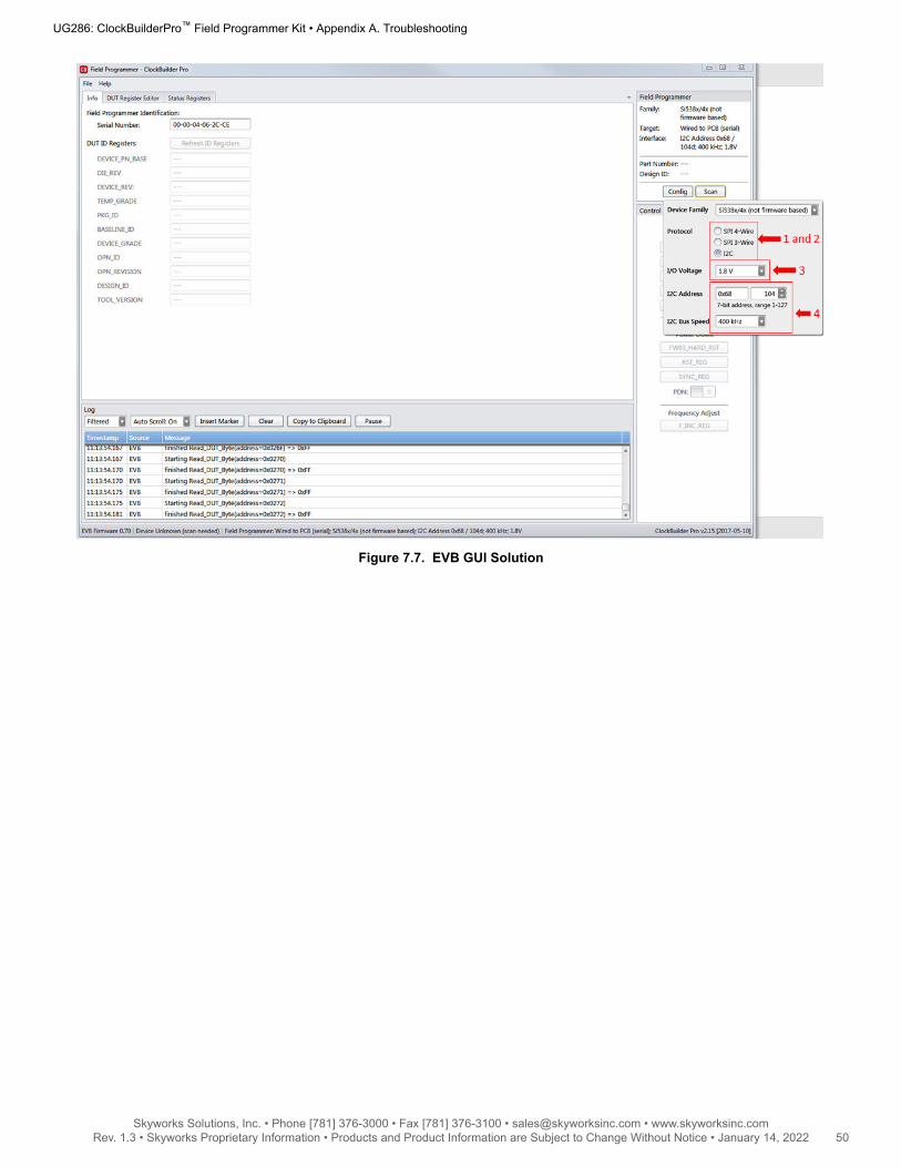
Figure 7.7. EVB GUI Solution
UG286: ClockBuilderPro™ Field Programmer Kit • Appendix A. Troubleshooting
Skyworks Solutions, Inc. • Phone [781] 376-3000 • Fax [781] 376-3100 • [email protected] • www.skyworksinc.com50 Rev. 1.3 • Skyworks Proprietary Information • Products and Product Information are Subject to Change Without Notice • January 14, 2022 50

7.2 Why do I have a communication error when I write my new project to the Si534x-8x-7x-9x device?
New Plan Changes the IO_VDD_SEL Bit (Register 0x0943[0]) Value
In order for the CBPro Dongle to communicate with the device correctly, the dongle’s IO voltage needs to match the IO_VDD_SEL bit inthe device. If the plan changes this bit during the writing process, communication will fail. To determine if the new plan is changing thisbit, perform the following steps:• Read the current value in the device by using the DUT Register Editor tab in the EVB GUI window.• Determine if the new plan changes the value. This can be done by looking at the Host Interface tab in the Design Dashboard of the
new project.• If VDD (Core) radio button selected and 0x943 = 0, no change from new plan,
Else VDD (Core) radio button selected and 0x943 = 1, new plan is changing IO_VDD_SEL refer to 7.3 How do I write a projectfile to the device that changes the I/O Power Supply setting in Si534x-8x-7x-9x devices (IO_VDD_SEL bit)?
• If VDDA (3.3 V) radio button selected and 0x943 = 1, no change from new plan,
Else VDDA (3.3 V) radio button selected and 0x943 = 0, new plan is changing IO_VDD_SEL refer to 7.3 How do I write a projectfile to the device that changes the I/O Power Supply setting in Si534x-8x-7x-9x devices (IO_VDD_SEL bit)?
The following window shows how to read the IO_VDD_SEL bit from the device.
Figure 7.8. Read IO_VDD_SEL Bit from Device
The following window shows how to determine the value of the IO_VDD_SEL bit that will be written to the device from the project file.
UG286: ClockBuilderPro™ Field Programmer Kit • Appendix A. Troubleshooting
Skyworks Solutions, Inc. • Phone [781] 376-3000 • Fax [781] 376-3100 • [email protected] • www.skyworksinc.com51 Rev. 1.3 • Skyworks Proprietary Information • Products and Product Information are Subject to Change Without Notice • January 14, 2022 51

Figure 7.9. Determine the Value of IO_VDD_SEL Bit Written to Device
UG286: ClockBuilderPro™ Field Programmer Kit • Appendix A. Troubleshooting
Skyworks Solutions, Inc. • Phone [781] 376-3000 • Fax [781] 376-3100 • [email protected] • www.skyworksinc.com52 Rev. 1.3 • Skyworks Proprietary Information • Products and Product Information are Subject to Change Without Notice • January 14, 2022 52
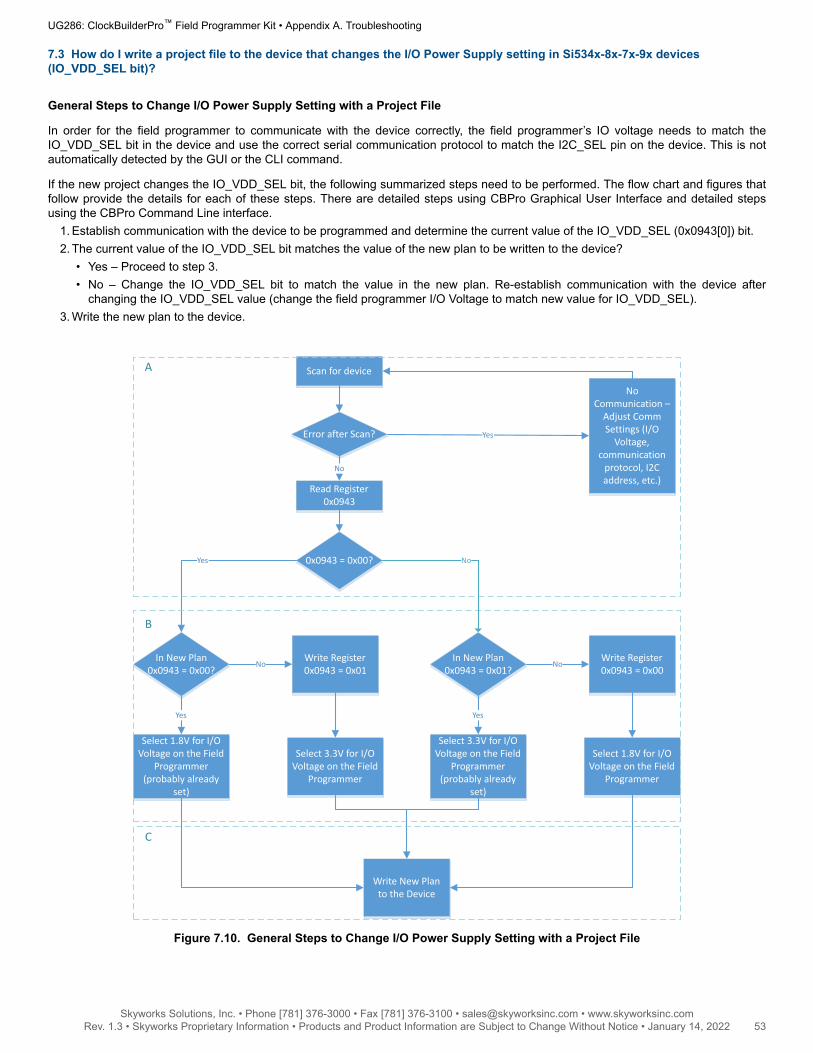
7.3 How do I write a project file to the device that changes the I/O Power Supply setting in Si534x-8x-7x-9x devices(IO_VDD_SEL bit)?
General Steps to Change I/O Power Supply Setting with a Project File
In order for the field programmer to communicate with the device correctly, the field programmer’s IO voltage needs to match theIO_VDD_SEL bit in the device and use the correct serial communication protocol to match the I2C_SEL pin on the device. This is notautomatically detected by the GUI or the CLI command.
If the new project changes the IO_VDD_SEL bit, the following summarized steps need to be performed. The flow chart and figures thatfollow provide the details for each of these steps. There are detailed steps using CBPro Graphical User Interface and detailed stepsusing the CBPro Command Line interface.
1. Establish communication with the device to be programmed and determine the current value of the IO_VDD_SEL (0x0943[0]) bit.2. The current value of the IO_VDD_SEL bit matches the value of the new plan to be written to the device?
• Yes – Proceed to step 3.• No – Change the IO_VDD_SEL bit to match the value in the new plan. Re-establish communication with the device after
changing the IO_VDD_SEL value (change the field programmer I/O Voltage to match new value for IO_VDD_SEL).3. Write the new plan to the device.
Scan for device
0x0943 = 0x00?
In New Plan0x0943 = 0x00?
Write Register 0x0943 = 0x01
No
Write New Plan to the Device
Select 3.3V for I/O Voltage on the Field
Programmer
Yes
Select 1.8V for I/O Voltage on the Field
Programmer (probably already
set)
Yes
In New Plan0x0943 = 0x01?
Write Register 0x0943 = 0x00
No
Select 1.8V for I/O Voltage on the Field
Programmer
Select 3.3V for I/O Voltage on the Field
Programmer (probably already
set)
Yes
No Communication –
Adjust Comm Settings (I/O
Voltage, communication
protocol, I2C address, etc.)
Error after Scan? Yes
A
B
C
No
Read Register 0x0943
No
Figure 7.10. General Steps to Change I/O Power Supply Setting with a Project File
UG286: ClockBuilderPro™ Field Programmer Kit • Appendix A. Troubleshooting
Skyworks Solutions, Inc. • Phone [781] 376-3000 • Fax [781] 376-3100 • [email protected] • www.skyworksinc.com53 Rev. 1.3 • Skyworks Proprietary Information • Products and Product Information are Subject to Change Without Notice • January 14, 2022 53

Steps using CBPro Graphical User Interface1. Select the ‘EVB GUI’ button on the home screen as shown to attempt communication with the device.
Figure 7.11. EVB GUI Button
a. Select the ‘DUT Register Editor’ tab.b. Determine the correct device communication protocol and setup CBPro accordingly as shown. For an In-socket device, click
the Socket Power slider to power up the device. For In-system devices, click the Device Family pulldown and select theappropriate device family.
c. Click the Scan button to verify communication with the device.d. If communication is successful, the device part number and design ID will be updated. If communication is not successful, the
part number field will display -ERR- and the DUT register tab will be disabled.
Configuring communication settings:
UG286: ClockBuilderPro™ Field Programmer Kit • Appendix A. Troubleshooting
Skyworks Solutions, Inc. • Phone [781] 376-3000 • Fax [781] 376-3100 • [email protected] • www.skyworksinc.com54 Rev. 1.3 • Skyworks Proprietary Information • Products and Product Information are Subject to Change Without Notice • January 14, 2022 54

Figure 7.12. Configuring Communication Settings
Examples of a Communication failure for I2C and SPI:
Figure 7.13. I2C and SPI Communication Failure Examples
UG286: ClockBuilderPro™ Field Programmer Kit • Appendix A. Troubleshooting
Skyworks Solutions, Inc. • Phone [781] 376-3000 • Fax [781] 376-3100 • [email protected] • www.skyworksinc.com55 Rev. 1.3 • Skyworks Proprietary Information • Products and Product Information are Subject to Change Without Notice • January 14, 2022 55

2. Match the IO_VDD_SEL bit to the value in the plan that will be written to the device.a. If the IO_VDD_SEL bit already matches the value in the plan to be written, skip to step 3.b. If the IO_VDD_SEL bit is not correct, change the value and write the new value to the device (see the figure below).c. Re-configure the communication settings of the field programmer to re-establish communication to the device.
Figure 7.14. Re-configuring Communication Settings of the Field Programmer
3. Write your new plan to the device.
Figure 7.15. Write New Plan to Device
UG286: ClockBuilderPro™ Field Programmer Kit • Appendix A. Troubleshooting
Skyworks Solutions, Inc. • Phone [781] 376-3000 • Fax [781] 376-3100 • [email protected] • www.skyworksinc.com56 Rev. 1.3 • Skyworks Proprietary Information • Products and Product Information are Subject to Change Without Notice • January 14, 2022 56

Steps using CBPro Command Line Interface1. Attempt to communicate with the Si534x8x7x9x device and determine the current value of the IO_VDD_SEL bit.
SPI communication Examples:
CBProDeviceRead.exe --io-voltage 1.8 --mode spi4wire --speed 1M --family si538x4x --registers 0x0943
CBProDeviceRead.exe --io-voltage 3.3 --mode spi4wire --speed 1M --family si538x4x --registers 0x0943
Note: The commands above are examples. Refer to the document and help for the CBPro CLI for your specific configuration.
I2C communication Examples:
CBProDeviceRead.exe --io-voltage 1.8 --mode i2c --speed 100k --i2c-address 0x68 --family si538x4x --registers 0x0943
CBProDeviceRead.exe --io-voltage 3.3 --mode i2c --speed 100k --i2c-address 0x68 --family si538x4x --registers 0x0943
Note: The commands above are examples. Refer to the document and help for the CBPro CLI for your specific configuration.
2. Match the IO_VDD_SEL bit to the value in the plan that will be written to the device.a. A simple text file will need to be created that will write register 0x943 to 0x00 or 0x01.
To write 0x01 to 0x0943, the text file should contain the following single line of text:
0x0943,0x01
To write 0x00 to 0x0943, the text file should contain the following single line of text:
0x0943,0x00
b. Run the CLI command below to change the IO_VDD_SEL bit.
SPI Example:
CBProDeviceWrite.exe --mode spi4wire --speed 4M --io-voltage 3.3 --family si538x4x --registers simple_text_file.txt
I2C Example:
CBProDeviceWrite.exe --mode i2c –i2c-address 0x68 --speed 400K --io-voltage 3.3 --family si538x4x --registers simple_text_file.txt
Note: The commands above are examples. Refer to the document and help for the CBPro CLI for your specific configuration.
3. Write the new plan to the part.
SPI Example:
CBProDeviceWrite.exe --mode spi4wire --speed 4M --io-voltage 3.3 --family si538x4x --project your_plan_name.slabtimeproj
I2C Example:
CBProDeviceWrite.exe --mode i2c –i2c-address 0x68 --speed 400K --io-voltage 3.3 --family si538x4x --project your_plan_name.slabtimeproj
Note: The commands above are examples. Refer to the document and help for the CBPro CLI for your specific configuration.
UG286: ClockBuilderPro™ Field Programmer Kit • Appendix A. Troubleshooting
Skyworks Solutions, Inc. • Phone [781] 376-3000 • Fax [781] 376-3100 • [email protected] • www.skyworksinc.com57 Rev. 1.3 • Skyworks Proprietary Information • Products and Product Information are Subject to Change Without Notice • January 14, 2022 57

7.4 I burned a project file to my device with a new Base I2C address, but the base address in the device was not changedafter the burn process was complete.
The I2C address will not be changed during the burn process. Changes to the base I2C address in the CBPro Configuration Wizardwill be included in exports and the project file used to create orderable part numbers. However, this change is not burned to the deviceusing the NVM Burn Tool. See the note highlighted in the figure below.
Figure 7.16. Base I2C Address
To permanently change the I2C base address on your device, you need to use the I2C Address Burn Tool. See the figures below to usethe tool.
Figure 7.17. I2C Address Burn Tool
UG286: ClockBuilderPro™ Field Programmer Kit • Appendix A. Troubleshooting
Skyworks Solutions, Inc. • Phone [781] 376-3000 • Fax [781] 376-3100 • [email protected] • www.skyworksinc.com58 Rev. 1.3 • Skyworks Proprietary Information • Products and Product Information are Subject to Change Without Notice • January 14, 2022 58

Copyright © 2022 Skyworks Solutions, Inc. All Rights Reserved.
nformation in this document is provided in connection with Skyworks Solutions, Inc. (“Skyworks”) products or services. These materials, including the information contained herein, are provided by Skyworks as a service to its customers and may be used for informational purposes only by the customer. Skyworks assumes no responsibility for errors or omissions in these materials or the information contained herein. Skyworks may change its documentation, products, services, specifications or product descriptions at any time, without notice. Skyworks makes no commitment to update the materials or information and shall have no responsibility whatsoever for conflicts, incompatibilities, or other difficulties arising from any future changes.
No license, whether express, implied, by estoppel or otherwise, is granted to any intellectual property rights by this document. Skyworks assumes no liability for any materials, products or information provided hereunder, including the sale, distribution, reproduction or use of Skyworks products, information or materials, except as may be provided in Skyworks’ Terms and Conditions of Sale.
THE MATERIALS, PRODUCTS AND INFORMATION ARE PROVIDED “AS IS” WITHOUT WARRANTY OF ANY KIND, WHETHER EXPRESS, IMPLIED, STATUTORY, OR OTHERWISE, INCLUDING FITNESS FOR A PARTICULAR PURPOSE OR USE, MERCHANTABILITY, PERFORMANCE, QUALITY OR NON-INFRINGEMENT OF ANY INTELLECTUAL PROPERTY RIGHT; ALL SUCH WARRANTIES ARE HEREBY EXPRESSLY DISCLAIMED. SKYWORKS DOES NOT WARRANT THE ACCURACY OR COMPLETENESS OF THE INFORMATION, TEXT, GRAPHICS OR OTHER ITEMS CONTAINED WITHIN THESE MATERIALS. SKYWORKS SHALL NOT BE LIABLE FOR ANY DAMAGES, INCLUDING BUT NOT LIMITED TO ANY SPECIAL, INDIRECT, INCIDENTAL, STATUTORY, OR CONSEQUENTIAL DAMAGES, INCLUDING WITHOUT LIMITATION, LOST REVENUES OR LOST PROFITS THAT MAY RESULT FROM THE USE OF THE MATERIALS OR INFORMATION, WHETHER OR NOT THE RECIPIENT OF MATERIALS HAS BEEN ADVISED OF THE POSSIBILITY OF SUCH DAMAGE
Skyworks products are not intended for use in medical, lifesaving or life-sustaining applications, or other equipment in which the failure of the Skyworks products could lead to personal injury, death, physical or environmental damage. Skyworks customers using or selling Skyworks products for use in such applications do so at their own risk and agree to fully indemnify Skyworks for any damages resulting from such improper use or sale.
Customers are responsible for their products and applications using Skyworks products, which may deviate from published specifications as a result of design defects, errors, or operation of products outside of published parameters or design specifications. Customers should include design and operating safeguards to minimize these and other risks. Skyworks assumes no liability for applications assistance, customer product design, or damage to any equipment resulting from the use of Skyworks products outside of Skyworks’ published specifications or parameters.
Skyworks, the Skyworks symbol, Sky5®, SkyOne®, SkyBlue™, Skyworks Green™, Clockbuilder®, DSPLL®, ISOmodem®, ProSLIC®, and SiPHY® are trademarks or registered trademarks of Skyworks Solutions, Inc. or its subsidiaries in the United States and other countries. Third-party brands and names are for identification purposes only and are the property of their respective owners. Additional information, including relevant terms and conditions, posted at www.skyworksinc.com, are incorporated by reference.
Skyworks Solutions, Inc. | Nasdaq: SWKS | [email protected] | www.skyworksinc.com
USA: 781-376-3000 | Asia: 886-2-2735 0399 | Europe: 33 (0)1 43548540
Portfolio
skyworksinc.com
Quality
skyworksinc.com/quality
SW/HW
skyworksinc.com/CBPro
Support & Resources
skyworksinc.com/support
ClockBuilder ProOne-click access to Timing tools,
documentation, software, source
code libraries & more. Available for
Windows and iOS (CBGo only).
skyworksinc.com/CBPro